

Page 1

OCX1100 Switch Hardware Guide
Modified: 2017-04-25
Copyright © 2017, Juniper Networks, Inc.
Page 2

Juniper Networks, Inc.
1133 Innovation Way
Sunnyvale, California 94089
USA
408-745-2000
www.juniper.net
Copyright © 2017, Juniper Networks, Inc. All rights reserved.
Juniper Networks, Junos, Steel-Belted Radius, NetScreen, and ScreenOS are registered trademarks of Juniper Networks, Inc. in the United
States and other countries. The Juniper Networks Logo, the Junos logo, and JunosE are trademarks of Juniper Networks, Inc. All other
trademarks, service marks, registered trademarks, or registered service marks are the property of their respective owners.
Juniper Networks assumes no responsibility for any inaccuracies in this document. Juniper Networks reserves the right to change, modify,
transfer, or otherwise revise this publication without notice.
OCX1100 Switch Hardware Guide
Copyright © 2017, Juniper Networks, Inc.
All rights reserved.
The information in this document is current as of the date on the title page.
YEAR 2000 NOTICE
Juniper Networks hardware and software products are Year 2000 compliant. Junos OS has no known time-related limitationsthrough the
year 2038. However, the NTP application is known to have some difficulty in the year 2036.
END USER LICENSE AGREEMENT
The Juniper Networks product that is the subject of this technical documentation consists of (or is intended for use with) Juniper Networks
software. Use of such software is subject tothe terms and conditions of the End User License Agreement (“EULA”) posted at
http://www.juniper.net/support/eula.html. By downloading, installing or using such software, you agree to the terms and conditions of
that EULA.
Copyright © 2017, Juniper Networks, Inc.ii
Page 3

Table of Contents
About the Documentation . . . . . . . . . . . . . . . . . . . . . . . . . . . . . . . . . . . . . . . . . . . . xv
Documentation and Release Notes . . . . . . . . . . . . . . . . . . . . . . . . . . . . . . . . . xv
Supported Platforms . . . . . . . . . . . . . . . . . . . . . . . . . . . . . . . . . . . . . . . . . . . . . xv
Documentation Conventions . . . . . . . . . . . . . . . . . . . . . . . . . . . . . . . . . . . . . . xv
Documentation Feedback . . . . . . . . . . . . . . . . . . . . . . . . . . . . . . . . . . . . . . . . xvii
Requesting Technical Support . . . . . . . . . . . . . . . . . . . . . . . . . . . . . . . . . . . . xviii
Self-Help Online Tools and Resources . . . . . . . . . . . . . . . . . . . . . . . . . . xviii
Opening a Case with JTAC . . . . . . . . . . . . . . . . . . . . . . . . . . . . . . . . . . . . xviii
Part 1 Overview
Chapter 1 System Overview . . . . . . . . . . . . . . . . . . . . . . . . . . . . . . . . . . . . . . . . . . . . . . . . . . . 3
OCX1100 Switches Hardware Overview . . . . . . . . . . . . . . . . . . . . . . . . . . . . . . . . . . 3
Software . . . . . . . . . . . . . . . . . . . . . . . . . . . . . . . . . . . . . . . . . . . . . . . . . . . . . . . 3
Hardware . . . . . . . . . . . . . . . . . . . . . . . . . . . . . . . . . . . . . . . . . . . . . . . . . . . . . . . 3
Power Supplies . . . . . . . . . . . . . . . . . . . . . . . . . . . . . . . . . . . . . . . . . . . . . . . . . . 4
Fan Modules . . . . . . . . . . . . . . . . . . . . . . . . . . . . . . . . . . . . . . . . . . . . . . . . . . . . 5
OCX1100-48SX Switch Components . . . . . . . . . . . . . . . . . . . . . . . . . . . . . . . . 6
OCX1100 Switch Models . . . . . . . . . . . . . . . . . . . . . . . . . . . . . . . . . . . . . . . . . . . . . . 6
OCX1100 Switch Hardware and CLI Terminology Mapping . . . . . . . . . . . . . . . . . . . 7
Chapter 2 Chassis Components and Descriptions . . . . . . . . . . . . . . . . . . . . . . . . . . . . . . . 11
Chassis Physical Specifications for OCX1100 Switches . . . . . . . . . . . . . . . . . . . . . . 11
Field-Replaceable Units in OCX1100 Switches . . . . . . . . . . . . . . . . . . . . . . . . . . . . 12
Chassis Status LEDs on OCX1100 Switches . . . . . . . . . . . . . . . . . . . . . . . . . . . . . . . 12
Management Port LEDs and Console Port LEDs on OCX1100 Switches . . . . . . . . 13
SFP+ Port and QSFP+ Port LEDs on OCX1100 Switches . . . . . . . . . . . . . . . . . . . . 14
Chapter 3 Cooling System and Airflow . . . . . . . . . . . . . . . . . . . . . . . . . . . . . . . . . . . . . . . . . 17
Cooling System and Airflow in an OCX1100 Switches . . . . . . . . . . . . . . . . . . . . . . . 17
Fan Modules . . . . . . . . . . . . . . . . . . . . . . . . . . . . . . . . . . . . . . . . . . . . . . . . . . . . 17
Airflow Direction in OCX1100-48SX Switch Models . . . . . . . . . . . . . . . . . . . . . 18
Front-to-Back Airflow . . . . . . . . . . . . . . . . . . . . . . . . . . . . . . . . . . . . . . . . . . . . 19
Back-to-Front Airflow . . . . . . . . . . . . . . . . . . . . . . . . . . . . . . . . . . . . . . . . . . . . 20
Do Not Install AIR IN (AFI) and AIR OUT (AFO) Components in the Same
Chassis . . . . . . . . . . . . . . . . . . . . . . . . . . . . . . . . . . . . . . . . . . . . . . . . . . . . 21
Positioning the Switch . . . . . . . . . . . . . . . . . . . . . . . . . . . . . . . . . . . . . . . . . . . . 21
iiiCopyright © 2017, Juniper Networks, Inc.
Page 4

OCX1100 Switch Hardware Guide
Chapter 4 Power Supplies . . . . . . . . . . . . . . . . . . . . . . . . . . . . . . . . . . . . . . . . . . . . . . . . . . . 23
Part 2 Site Planning, Preparation, and Specifications
Chapter 5 Preparation Overview . . . . . . . . . . . . . . . . . . . . . . . . . . . . . . . . . . . . . . . . . . . . . . 31
Chapter 6 Power Specifications and Requirements . . . . . . . . . . . . . . . . . . . . . . . . . . . . . 41
Chapter 7 Transceiver and Cable Specifications . . . . . . . . . . . . . . . . . . . . . . . . . . . . . . . . 47
Chapter 8 Pinout Specifications . . . . . . . . . . . . . . . . . . . . . . . . . . . . . . . . . . . . . . . . . . . . . . 55
AC Power Supply in OCX1100 Switches . . . . . . . . . . . . . . . . . . . . . . . . . . . . . . . . . 23
Characteristics of an AC Power Supply . . . . . . . . . . . . . . . . . . . . . . . . . . . . . . 23
AC Power Supply Airflow . . . . . . . . . . . . . . . . . . . . . . . . . . . . . . . . . . . . . . 25
DC Power Supply in OCX1100 Switches . . . . . . . . . . . . . . . . . . . . . . . . . . . . . . . . . 25
Characteristics of a DC Power Supply . . . . . . . . . . . . . . . . . . . . . . . . . . . . . . . 26
DC Power Supply Airflow . . . . . . . . . . . . . . . . . . . . . . . . . . . . . . . . . . . . . . 27
Power Supply LEDs in OCX1100 Switches . . . . . . . . . . . . . . . . . . . . . . . . . . . . . . . . 27
Site Preparation Checklist for OCX1100 Switches . . . . . . . . . . . . . . . . . . . . . . . . . . 31
Environmental Requirements and Specifications for OCX1100 Switches . . . . . . . 32
General Site Guidelines . . . . . . . . . . . . . . . . . . . . . . . . . . . . . . . . . . . . . . . . . . . . . . 33
Site Electrical Wiring Guidelines . . . . . . . . . . . . . . . . . . . . . . . . . . . . . . . . . . . . . . . 34
Chassis Physical Specifications for OCX1100 Switches . . . . . . . . . . . . . . . . . . . . . 35
Requirements for Mounting an OCX1100 Switch on a Desktop or Other Level
Surface . . . . . . . . . . . . . . . . . . . . . . . . . . . . . . . . . . . . . . . . . . . . . . . . . . . . . . . 35
Rack Requirements . . . . . . . . . . . . . . . . . . . . . . . . . . . . . . . . . . . . . . . . . . . . . . . . . 35
Cabinet Requirements . . . . . . . . . . . . . . . . . . . . . . . . . . . . . . . . . . . . . . . . . . . . . . . 36
Clearance Requirements for Airflow and Hardware Maintenance for OCX1100
Switches . . . . . . . . . . . . . . . . . . . . . . . . . . . . . . . . . . . . . . . . . . . . . . . . . . . . . . 37
AC Power Supply Specifications for OCX1100 Switches . . . . . . . . . . . . . . . . . . . . . 41
AC Power Cord Specifications for an OCX1100 Switch . . . . . . . . . . . . . . . . . . . . . . 41
DC Power Supply Specifications for OCX1100 Switches . . . . . . . . . . . . . . . . . . . . 44
Pluggable Transceivers Supported on OCX1100 Switches . . . . . . . . . . . . . . . . . . . 47
SFP+ Direct Attach Cables for OCX1100 Switches . . . . . . . . . . . . . . . . . . . . . . . . . 50
Cable Specifications . . . . . . . . . . . . . . . . . . . . . . . . . . . . . . . . . . . . . . . . . . . . . 51
Standards Supported by These Cables . . . . . . . . . . . . . . . . . . . . . . . . . . . . . . 53
Management Cable Specifications . . . . . . . . . . . . . . . . . . . . . . . . . . . . . . . . . . . . . 53
Console Port Connector Pinout Information . . . . . . . . . . . . . . . . . . . . . . . . . . . . . . 55
Mini-USB Port Pinout Specifications . . . . . . . . . . . . . . . . . . . . . . . . . . . . . . . . . . . 56
RJ-45 Management Port Connector Pinout Information . . . . . . . . . . . . . . . . . . . . 56
RJ-45 to DB-9 Serial Port Adapter Pinout Information . . . . . . . . . . . . . . . . . . . . . . 57
RJ-45 Port, QSFP+ Port, SFP+ Port, and SFP Port Connector Pinout
Information . . . . . . . . . . . . . . . . . . . . . . . . . . . . . . . . . . . . . . . . . . . . . . . . . . . . 58
Part 3 Initial Installation and Configuration
Chapter 9 Unpacking the Switch . . . . . . . . . . . . . . . . . . . . . . . . . . . . . . . . . . . . . . . . . . . . . 65
Unpacking an OCX1100 Switch . . . . . . . . . . . . . . . . . . . . . . . . . . . . . . . . . . . . . . . . 65
Parts Inventory (Packing List) for an OCX1100 Switch . . . . . . . . . . . . . . . . . . . . . . 66
Registering Products—Mandatory for Validating SLAs . . . . . . . . . . . . . . . . . . . . . . 67
Copyright © 2017, Juniper Networks, Inc.iv
Page 5

Table of Contents
Chapter 10 Installing the Switch . . . . . . . . . . . . . . . . . . . . . . . . . . . . . . . . . . . . . . . . . . . . . . 69
Installing and Connecting an OCX1100 Switch . . . . . . . . . . . . . . . . . . . . . . . . . . . . 69
Mounting an OCX1100 Switch . . . . . . . . . . . . . . . . . . . . . . . . . . . . . . . . . . . . . . . . . 70
Mounting an OCX1100 Switch on a Desk or Other Level Surface . . . . . . . . . . . . . . 70
Mounting an OCX1100 Switch on Four Posts of a Rack or Cabinet . . . . . . . . . . . . . 71
Installing and Removing OCX1100 Switch Hardware Components . . . . . . . . . . . . 74
Chapter 11 Connecting the Switch to Power . . . . . . . . . . . . . . . . . . . . . . . . . . . . . . . . . . . . . 77
Installing an AC Power Supply in an OCX1100 Switch . . . . . . . . . . . . . . . . . . . . . . . 77
Installing a DC Power Supply in an OCX1100 Switch . . . . . . . . . . . . . . . . . . . . . . . 79
Connecting AC Power to an OCX1100 Switch . . . . . . . . . . . . . . . . . . . . . . . . . . . . 80
Connecting DC Power to an OCX1100 Switch . . . . . . . . . . . . . . . . . . . . . . . . . . . . . 82
Chapter 12 Connecting the Switch to the Network . . . . . . . . . . . . . . . . . . . . . . . . . . . . . . . 85
Connecting a Device to a Network for Out-of-Band Management . . . . . . . . . . . . 85
Connecting a Device to a Management Console by Using an RJ-45
Connector . . . . . . . . . . . . . . . . . . . . . . . . . . . . . . . . . . . . . . . . . . . . . . . . . . . . . 86
ConnectinganOCX1100Switch to a Management Consoleby Using the Mini-USB
Type-B Console Port . . . . . . . . . . . . . . . . . . . . . . . . . . . . . . . . . . . . . . . . . . . . . 87
Connecting a Fiber-Optic Cable . . . . . . . . . . . . . . . . . . . . . . . . . . . . . . . . . . . . . . . 89
Chapter 13 Initially Configuring the Switch . . . . . . . . . . . . . . . . . . . . . . . . . . . . . . . . . . . . . . 91
OCX1100 Default Configuration . . . . . . . . . . . . . . . . . . . . . . . . . . . . . . . . . . . . . . . . 91
Connecting and Configuring an OCX1100 Switch (CLI Procedure) . . . . . . . . . . . 100
Part 4 Installing, Maintaining, and Replacing Components
Chapter 14 Replacing Cooling System Component . . . . . . . . . . . . . . . . . . . . . . . . . . . . . 105
Installing a Fan Module in an OCX1100 Switch . . . . . . . . . . . . . . . . . . . . . . . . . . . 105
Removing a Fan Module from an OCX1100 Switch . . . . . . . . . . . . . . . . . . . . . . . . 106
Chapter 15 Replacing Power Supply . . . . . . . . . . . . . . . . . . . . . . . . . . . . . . . . . . . . . . . . . . 109
Installing an AC Power Supply in an OCX1100 Switch . . . . . . . . . . . . . . . . . . . . . 109
Removing an AC Power Supply from an OCX1100 Switch . . . . . . . . . . . . . . . . . . . 111
Installing a DC Power Supply in an OCX1100 Switch . . . . . . . . . . . . . . . . . . . . . . . 112
Removing a DC Power Supply from an OCX1100 Switch . . . . . . . . . . . . . . . . . . . . 114
Chapter 16 Replacing Transceiver . . . . . . . . . . . . . . . . . . . . . . . . . . . . . . . . . . . . . . . . . . . . . 117
Installing a Transceiver . . . . . . . . . . . . . . . . . . . . . . . . . . . . . . . . . . . . . . . . . . . . . . 117
Removing a Transceiver . . . . . . . . . . . . . . . . . . . . . . . . . . . . . . . . . . . . . . . . . . . . . . 119
Chapter 17 Maintaining and Replacing Fiber-Optic Cable . . . . . . . . . . . . . . . . . . . . . . . . 123
Connecting a Fiber-Optic Cable . . . . . . . . . . . . . . . . . . . . . . . . . . . . . . . . . . . . . . . 123
Disconnecting a Fiber-Optic Cable from a Device . . . . . . . . . . . . . . . . . . . . . . . . . 124
Maintaining Fiber-Optic Cables . . . . . . . . . . . . . . . . . . . . . . . . . . . . . . . . . . . . . . . 125
Chapter 18 Contacting Customer Support and Returning the Chassis or
Components . . . . . . . . . . . . . . . . . . . . . . . . . . . . . . . . . . . . . . . . . . . . . . . . . . . . . 127
Returning an OCX1100 Switch or Component for Repair or Replacement . . . . . . 127
Locating the Serial Number on an OCX1100 Switch or Component . . . . . . . . . . . 128
Listing the Switch and Components Details with the CLI . . . . . . . . . . . . . . . 128
Locating the Chassis Serial Number ID Label on an OCX1100 Switch . . . . . 129
vCopyright © 2017, Juniper Networks, Inc.
Page 6

OCX1100 Switch Hardware Guide
Part 5 Safety and Compliance Information
Chapter 19 General Safety Guidelines and Warnings . . . . . . . . . . . . . . . . . . . . . . . . . . . . 137
Chapter 20 Fire Safety Requirements . . . . . . . . . . . . . . . . . . . . . . . . . . . . . . . . . . . . . . . . . . 143
Chapter 21 Installation Safety Guidelines and Warnings . . . . . . . . . . . . . . . . . . . . . . . . . 145
Chapter 22 Radiation and Laser Safety Guidelines and Warnings . . . . . . . . . . . . . . . . . 155
Chapter 23 Maintenance and Operational Safety Warnings . . . . . . . . . . . . . . . . . . . . . . 159
Chapter 24 Electrical Safety Guidelines and Warnings . . . . . . . . . . . . . . . . . . . . . . . . . . . 165
Locating the Serial Number ID Labels on FRUs in an OCX1100 Switch . . . . . 129
Contacting Customer Support to Obtain Return Material Authorization . . . . . . . 130
Packing an OCX1100 Switch or Component for Shipping . . . . . . . . . . . . . . . . . . . 131
Packing an OCX1100 Switch for Shipping . . . . . . . . . . . . . . . . . . . . . . . . . . . . 132
Packing OCX1100 Switch Components for Shipping . . . . . . . . . . . . . . . . . . . 133
General Safety Guidelines and Warnings . . . . . . . . . . . . . . . . . . . . . . . . . . . . . . . . 137
Definitions of Safety Warning Levels . . . . . . . . . . . . . . . . . . . . . . . . . . . . . . . . . . . 138
Qualified Personnel Warning . . . . . . . . . . . . . . . . . . . . . . . . . . . . . . . . . . . . . . . . . 140
Warning Statement for Norway and Sweden . . . . . . . . . . . . . . . . . . . . . . . . . . . . . 141
Fire Safety Requirements . . . . . . . . . . . . . . . . . . . . . . . . . . . . . . . . . . . . . . . . . . . . 143
Installation Instructions Warning . . . . . . . . . . . . . . . . . . . . . . . . . . . . . . . . . . . . . . 145
Chassis Lifting Guidelines . . . . . . . . . . . . . . . . . . . . . . . . . . . . . . . . . . . . . . . . . . . 146
Restricted Access Warning . . . . . . . . . . . . . . . . . . . . . . . . . . . . . . . . . . . . . . . . . . . 146
Ramp Warning . . . . . . . . . . . . . . . . . . . . . . . . . . . . . . . . . . . . . . . . . . . . . . . . . . . . 148
Rack-Mounting and Cabinet-Mounting Warnings . . . . . . . . . . . . . . . . . . . . . . . . 148
Grounded Equipment Warning . . . . . . . . . . . . . . . . . . . . . . . . . . . . . . . . . . . . . . . . 152
Laser and LED Safety Guidelines and Warnings . . . . . . . . . . . . . . . . . . . . . . . . . . 155
General Laser Safety Guidelines . . . . . . . . . . . . . . . . . . . . . . . . . . . . . . . . . . . 155
Class 1 Laser Product Warning . . . . . . . . . . . . . . . . . . . . . . . . . . . . . . . . . . . . 156
Class 1 LED Product Warning . . . . . . . . . . . . . . . . . . . . . . . . . . . . . . . . . . . . . 156
Laser Beam Warning . . . . . . . . . . . . . . . . . . . . . . . . . . . . . . . . . . . . . . . . . . . . 156
Radiation from Open Port Apertures Warning . . . . . . . . . . . . . . . . . . . . . . . . . . . . 157
Maintenance and Operational Safety Guidelines and Warnings . . . . . . . . . . . . . 159
Battery Handling Warning . . . . . . . . . . . . . . . . . . . . . . . . . . . . . . . . . . . . . . . . 159
Jewelry Removal Warning . . . . . . . . . . . . . . . . . . . . . . . . . . . . . . . . . . . . . . . . 160
Lightning Activity Warning . . . . . . . . . . . . . . . . . . . . . . . . . . . . . . . . . . . . . . . . 161
Operating Temperature Warning . . . . . . . . . . . . . . . . . . . . . . . . . . . . . . . . . . 162
Product Disposal Warning . . . . . . . . . . . . . . . . . . . . . . . . . . . . . . . . . . . . . . . . 163
General Electrical Safety Guidelines and Warnings . . . . . . . . . . . . . . . . . . . . . . . 165
Action to Take After an Electrical Accident . . . . . . . . . . . . . . . . . . . . . . . . . . . . . . 166
Prevention of Electrostatic Discharge Damage . . . . . . . . . . . . . . . . . . . . . . . . . . . 167
AC Power Electrical Safety Guidelines . . . . . . . . . . . . . . . . . . . . . . . . . . . . . . . . . . 168
AC Power Disconnection Warning . . . . . . . . . . . . . . . . . . . . . . . . . . . . . . . . . . . . . 169
DC Power Electrical Safety Guidelines for Switches . . . . . . . . . . . . . . . . . . . . . . . 170
DC Power Disconnection Warning . . . . . . . . . . . . . . . . . . . . . . . . . . . . . . . . . . . . . 173
DC Power Grounding Requirements and Warning . . . . . . . . . . . . . . . . . . . . . . . . . 174
DC Power Wiring Sequence Warning . . . . . . . . . . . . . . . . . . . . . . . . . . . . . . . . . . . 175
Copyright © 2017, Juniper Networks, Inc.vi
Page 7

Table of Contents
DC Power Wiring Terminations Warning . . . . . . . . . . . . . . . . . . . . . . . . . . . . . . . . . 177
Multiple Power Supplies Disconnection Warning . . . . . . . . . . . . . . . . . . . . . . . . . 178
TN Power Warning . . . . . . . . . . . . . . . . . . . . . . . . . . . . . . . . . . . . . . . . . . . . . . . . . 178
Chapter 25 Agency Approvals and Compliance Statements . . . . . . . . . . . . . . . . . . . . . . 181
Agency Approvals for OCX1100 Switches . . . . . . . . . . . . . . . . . . . . . . . . . . . . . . . . 181
Compliance Statements for EMC Requirements for OCX1100 Switches . . . . . . . 182
Canada . . . . . . . . . . . . . . . . . . . . . . . . . . . . . . . . . . . . . . . . . . . . . . . . . . . . . . . 182
European Community . . . . . . . . . . . . . . . . . . . . . . . . . . . . . . . . . . . . . . . . . . . 183
Israel . . . . . . . . . . . . . . . . . . . . . . . . . . . . . . . . . . . . . . . . . . . . . . . . . . . . . . . . . 183
Japan . . . . . . . . . . . . . . . . . . . . . . . . . . . . . . . . . . . . . . . . . . . . . . . . . . . . . . . . 183
Korea . . . . . . . . . . . . . . . . . . . . . . . . . . . . . . . . . . . . . . . . . . . . . . . . . . . . . . . . 183
United States . . . . . . . . . . . . . . . . . . . . . . . . . . . . . . . . . . . . . . . . . . . . . . . . . . 184
FCC Part 15 Statement . . . . . . . . . . . . . . . . . . . . . . . . . . . . . . . . . . . . . . . . . . 184
Compliance Statements for Acoustic Noise for OCX1100 Switches . . . . . . . . . . 184
viiCopyright © 2017, Juniper Networks, Inc.
Page 8

OCX1100 Switch Hardware Guide
Copyright © 2017, Juniper Networks, Inc.viii
Page 9

List of Figures
Part 1 Overview
Chapter 1 System Overview . . . . . . . . . . . . . . . . . . . . . . . . . . . . . . . . . . . . . . . . . . . . . . . . . . . 3
Figure 1: Front Panel of an OCX1100-48SX Switch . . . . . . . . . . . . . . . . . . . . . . . . . . 4
Figure 2: Rear Panel of an OCX1100-48SX Switch . . . . . . . . . . . . . . . . . . . . . . . . . . 4
Figure 3: Components on the Front Panel of an OCX1100-48SX Switch . . . . . . . . 6
Figure 4: Components on the Rear Panel of an OCX1100-48SX Switch . . . . . . . . . 6
Chapter 2 Chassis Components and Descriptions . . . . . . . . . . . . . . . . . . . . . . . . . . . . . . . 11
Figure 5: Chassis Status LEDs in an OCX1100-48SX Switch . . . . . . . . . . . . . . . . . . 12
Figure 6: LEDs on the Management Port and Console Port on an OCX1100-48SX
Switch . . . . . . . . . . . . . . . . . . . . . . . . . . . . . . . . . . . . . . . . . . . . . . . . . . . . . . . . 14
Figure 7: LEDs on SFP+ Ports . . . . . . . . . . . . . . . . . . . . . . . . . . . . . . . . . . . . . . . . . . 15
Figure 8: LEDs on QSFP+ Ports . . . . . . . . . . . . . . . . . . . . . . . . . . . . . . . . . . . . . . . . 15
Chapter 3 Cooling System and Airflow . . . . . . . . . . . . . . . . . . . . . . . . . . . . . . . . . . . . . . . . . 17
Figure 9: Fan Module Used in an OCX1100 Switch . . . . . . . . . . . . . . . . . . . . . . . . . 18
Figure 10: Location of Airflow Labels on the Power Supplies and Fan Modules
of an OCX1100-48SX Switch . . . . . . . . . . . . . . . . . . . . . . . . . . . . . . . . . . . . . . 19
Figure 11: Front-to-Back Airflow Through OCX1100-48SX Switch Chassis . . . . . . 20
Figure 12: Back-to-Front Airflow Through the OCX1100-48SX Switch Chassis . . . 20
Chapter 4 Power Supplies . . . . . . . . . . . . . . . . . . . . . . . . . . . . . . . . . . . . . . . . . . . . . . . . . . . 23
Figure 13: AC Power Supply for an OCX1100 Switch . . . . . . . . . . . . . . . . . . . . . . . . 24
Figure 14: DC Power Supply for an OCX1100 Switch . . . . . . . . . . . . . . . . . . . . . . . . 26
Figure 15: AC Power Supply LED in an OCX1100 Switch . . . . . . . . . . . . . . . . . . . . . 27
Figure 16: DC Power Supply LED in an OCX1100 Switch . . . . . . . . . . . . . . . . . . . . . 28
Part 2 Site Planning, Preparation, and Specifications
Chapter 5 Preparation Overview . . . . . . . . . . . . . . . . . . . . . . . . . . . . . . . . . . . . . . . . . . . . . . 31
Figure 17: Front-to-Back Airflow Through OCX1100-48SX Switch Chassis . . . . . . 38
Figure 18: Back-to-Front Airflow Through the OCX1100-48SX Switch Chassis . . 38
Figure 19: Clearance Requirements for Airflow and Hardware Maintenance for
an OCX1100-48SX Switch Chassis . . . . . . . . . . . . . . . . . . . . . . . . . . . . . . . . . 39
Part 3 Initial Installation and Configuration
Chapter 10 Installing the Switch . . . . . . . . . . . . . . . . . . . . . . . . . . . . . . . . . . . . . . . . . . . . . . 69
Figure 20: Attaching Rubber Feet to the Switch Chassis . . . . . . . . . . . . . . . . . . . . . 71
Figure 21: Attaching the Front Rack-Mounting Brackets to the Switch Chassis . . . 72
Figure 22: Attaching the Rack-Mounting Slider Brackets to the Rack Posts . . . . . 73
ixCopyright © 2017, Juniper Networks, Inc.
Page 10

OCX1100 Switch Hardware Guide
Chapter 11 Connecting the Switch to Power . . . . . . . . . . . . . . . . . . . . . . . . . . . . . . . . . . . . . 77
Chapter 12 Connecting the Switch to the Network . . . . . . . . . . . . . . . . . . . . . . . . . . . . . . . 85
Figure 23: Sliding the Switch into Rack-Mounting Slider Brackets and Mounting
the Switch to the Front Posts of the Rack . . . . . . . . . . . . . . . . . . . . . . . . . . . . 74
Figure 24: Installing an AC Power Supply in an OCX1100-48SX Switch . . . . . . . . 78
Figure 25: Installing a DC Power Supply in an OCX1100-48SX Switch . . . . . . . . . 80
Figure 26: Connecting an AC Power Cord to an AC Power Supply in an OCX1100
Switch . . . . . . . . . . . . . . . . . . . . . . . . . . . . . . . . . . . . . . . . . . . . . . . . . . . . . . . . 82
Figure 27: Connecting a DC Power Cord to a DC Power Supply in an OCX1100
Switch . . . . . . . . . . . . . . . . . . . . . . . . . . . . . . . . . . . . . . . . . . . . . . . . . . . . . . . . 83
Figure 28: RJ-45 Connector on an Ethernet Cable . . . . . . . . . . . . . . . . . . . . . . . . . 85
Figure 29: Connecting a Device to a Network for Out-of-Band Management . . . 86
Figure 30: RJ-45 Connector on an Ethernet Cable . . . . . . . . . . . . . . . . . . . . . . . . . 86
Figure 31: Connecting a Device to a Management Console Through a Console
Server . . . . . . . . . . . . . . . . . . . . . . . . . . . . . . . . . . . . . . . . . . . . . . . . . . . . . . . . . 87
Figure 32: Connecting a Device Directly to a Management Console . . . . . . . . . . . 87
Figure 33: Connecting a Fiber-Optic Cable to an Optical Transceiver Installed in
a Device . . . . . . . . . . . . . . . . . . . . . . . . . . . . . . . . . . . . . . . . . . . . . . . . . . . . . . . 89
Part 4 Installing, Maintaining, and Replacing Components
Chapter 14 Replacing Cooling System Component . . . . . . . . . . . . . . . . . . . . . . . . . . . . . 105
Figure 34: Installing a Fan Module in an OCX1100–48SX Switch . . . . . . . . . . . . . 106
Figure 35: Removing a Fan Module from an OCX1100-48SX Switch . . . . . . . . . . 107
Chapter 15 Replacing Power Supply . . . . . . . . . . . . . . . . . . . . . . . . . . . . . . . . . . . . . . . . . . 109
Figure 36: Installing an AC Power Supply in an OCX1100-48SX Switch . . . . . . . . 110
Figure 37: Removing an AC Power Supply from an OCX1100-48SX Switch . . . . . 112
Figure 38: Installing a DC Power Supply in an OCX1100-48SX Switch . . . . . . . . . 114
Figure 39: Removing a DC Power Supply from an OCX1100-48SX Switch . . . . . . 115
Chapter 16 Replacing Transceiver . . . . . . . . . . . . . . . . . . . . . . . . . . . . . . . . . . . . . . . . . . . . . 117
Figure 40: Installing a Transceiver . . . . . . . . . . . . . . . . . . . . . . . . . . . . . . . . . . . . . . 119
Figure 41: Removing an SFP, SFP+, XFP, or a QSFP+ Transceiver . . . . . . . . . . . . . 121
Chapter 17 Maintaining and Replacing Fiber-Optic Cable . . . . . . . . . . . . . . . . . . . . . . . . 123
Figure 42: Connecting a Fiber-Optic Cable to an Optical Transceiver Installed in
a Device . . . . . . . . . . . . . . . . . . . . . . . . . . . . . . . . . . . . . . . . . . . . . . . . . . . . . . 124
Chapter 18 Contacting Customer Support and Returning the Chassis or
Components . . . . . . . . . . . . . . . . . . . . . . . . . . . . . . . . . . . . . . . . . . . . . . . . . . . . . 127
Figure 43: Location of the Serial Number ID Label on OCX1100 Switches . . . . . . 129
Figure 44: Location of the Serial Number ID Label on an AC Power Supply Used
in an OCX1100 Switch . . . . . . . . . . . . . . . . . . . . . . . . . . . . . . . . . . . . . . . . . . . 129
Figure 45: Location of the Serial Number ID Label on a DC Power Supply Used
in an OCX1100 Switch . . . . . . . . . . . . . . . . . . . . . . . . . . . . . . . . . . . . . . . . . . . 130
Figure 46: Location of the Serial Number ID Label on the Fan Module Used in an
OCX1100 Switch . . . . . . . . . . . . . . . . . . . . . . . . . . . . . . . . . . . . . . . . . . . . . . . 130
Copyright © 2017, Juniper Networks, Inc.x
Page 11

List of Figures
Part 5 Safety and Compliance Information
Chapter 24 Electrical Safety Guidelines and Warnings . . . . . . . . . . . . . . . . . . . . . . . . . . . 165
Figure 47: Placing a Component into an Antistatic Bag . . . . . . . . . . . . . . . . . . . . 168
xiCopyright © 2017, Juniper Networks, Inc.
Page 12

OCX1100 Switch Hardware Guide
Copyright © 2017, Juniper Networks, Inc.xii
Page 13

List of Tables
About the Documentation . . . . . . . . . . . . . . . . . . . . . . . . . . . . . . . . . . . . . . . . . . xv
Table 1: Notice Icons . . . . . . . . . . . . . . . . . . . . . . . . . . . . . . . . . . . . . . . . . . . . . . . . . xvi
Table 2: Text and Syntax Conventions . . . . . . . . . . . . . . . . . . . . . . . . . . . . . . . . . . xvi
Part 1 Overview
Chapter 1 System Overview . . . . . . . . . . . . . . . . . . . . . . . . . . . . . . . . . . . . . . . . . . . . . . . . . . . 3
Table 3: Airflow Direction in Power Supply for OCX1100 Switches . . . . . . . . . . . . . . 5
Table 4: OCX1100-48SX Switch Models, Shipped Components, and Supported
Table 5: CLI Equivalents of TermsUsed in the Documentation for OCX1100-48SX
Chapter 2 Chassis Components and Descriptions . . . . . . . . . . . . . . . . . . . . . . . . . . . . . . . 11
Table 6: Physical Specifications of the OCX1100-48SX Switch Chassis . . . . . . . . . 11
Table 7: Chassis Status LEDs on an OCX1100-48SX Switch . . . . . . . . . . . . . . . . . . 13
Table 8: Link and Activity LED on the Management Port of an OCX1100-48SX
Table 9: Status LED on the Console Port of an OCX1100-48SX Switch . . . . . . . . . 14
Table 10: Link and Activity LED on SFP+ Ports . . . . . . . . . . . . . . . . . . . . . . . . . . . . . 15
Table 11: Link/Activity LED on QSFP+ Ports . . . . . . . . . . . . . . . . . . . . . . . . . . . . . . . 15
Chapter 3 Cooling System and Airflow . . . . . . . . . . . . . . . . . . . . . . . . . . . . . . . . . . . . . . . . . 17
Table 12: Fan Modules in OCX1100-48SX Switches . . . . . . . . . . . . . . . . . . . . . . . . 18
Table 13: Airflow Direction in OCX1100-48SX Switch Models . . . . . . . . . . . . . . . . . 18
Chapter 4 Power Supplies . . . . . . . . . . . . . . . . . . . . . . . . . . . . . . . . . . . . . . . . . . . . . . . . . . . 23
Table 14: Details of the AC Power Supplies in OCX1100-48SX Switches . . . . . . . 24
Table 15: Airflow Direction in AC Power Supply Models for OCX1100-48SX
Table 16: Details of the DC Power Supplies in OCX1100-48SX Switches . . . . . . . 26
Table 17: Airflow Direction in AC Power Supply Models for OCX1100-48SX
Table 18: Power Supply LED in OCX1100 Switches . . . . . . . . . . . . . . . . . . . . . . . . . 28
Junos OS Release . . . . . . . . . . . . . . . . . . . . . . . . . . . . . . . . . . . . . . . . . . . . . . . . 7
Switches . . . . . . . . . . . . . . . . . . . . . . . . . . . . . . . . . . . . . . . . . . . . . . . . . . . . . . . 7
Switch . . . . . . . . . . . . . . . . . . . . . . . . . . . . . . . . . . . . . . . . . . . . . . . . . . . . . . . . 14
Switches . . . . . . . . . . . . . . . . . . . . . . . . . . . . . . . . . . . . . . . . . . . . . . . . . . . . . . 25
Switches . . . . . . . . . . . . . . . . . . . . . . . . . . . . . . . . . . . . . . . . . . . . . . . . . . . . . . 27
Part 2 Site Planning, Preparation, and Specifications
Chapter 5 Preparation Overview . . . . . . . . . . . . . . . . . . . . . . . . . . . . . . . . . . . . . . . . . . . . . . 31
Table 19: Site Preparation Checklist . . . . . . . . . . . . . . . . . . . . . . . . . . . . . . . . . . . . . 31
Table 20: OCX1100 Switch Environmental Tolerances . . . . . . . . . . . . . . . . . . . . . . 33
Table 21: Site Electrical Wiring Guidelines . . . . . . . . . . . . . . . . . . . . . . . . . . . . . . . . 34
Table 22: Physical Specifications of the OCX1100-48SX Switch Chassis . . . . . . . 35
xiiiCopyright © 2017, Juniper Networks, Inc.
Page 14

OCX1100 Switch Hardware Guide
Chapter 6 Power Specifications and Requirements . . . . . . . . . . . . . . . . . . . . . . . . . . . . . 41
Chapter 7 Transceiver and Cable Specifications . . . . . . . . . . . . . . . . . . . . . . . . . . . . . . . . 47
Chapter 8 Pinout Specifications . . . . . . . . . . . . . . . . . . . . . . . . . . . . . . . . . . . . . . . . . . . . . . 55
Table 23: Rack Requirements and Specifications . . . . . . . . . . . . . . . . . . . . . . . . . . 36
Table 24: Cabinet Requirements and Specifications . . . . . . . . . . . . . . . . . . . . . . . 37
Table 25: 460 W AC Power Supply Specifications for an OCX1100 Switch . . . . . . 41
Table 26: AC Power Cord Specifications for 460 W AC Power Supplies for an
OCX1100 Switch . . . . . . . . . . . . . . . . . . . . . . . . . . . . . . . . . . . . . . . . . . . . . . . . 42
Table 27: DC Power Supply Specifications for an OCX1100 Switch . . . . . . . . . . . . 44
Table 28: Optical Interface Support for SFP+ Transceivers in OCX1100
Switches . . . . . . . . . . . . . . . . . . . . . . . . . . . . . . . . . . . . . . . . . . . . . . . . . . . . . . 48
Table 29: Optical Interface Support for QSFP+ Transceivers in OCX1100
Switches . . . . . . . . . . . . . . . . . . . . . . . . . . . . . . . . . . . . . . . . . . . . . . . . . . . . . . 50
Table 30: Software Support for SFP+ Passive Direct Attach Cables for OCX1100
Switches . . . . . . . . . . . . . . . . . . . . . . . . . . . . . . . . . . . . . . . . . . . . . . . . . . . . . . . 51
Table 31: SFP+ Direct Attach Cable Specifications . . . . . . . . . . . . . . . . . . . . . . . . . 52
Table 32: Specifications of Cables to Connect to Management Devices . . . . . . . . 53
Table 33: Console Port Connector Pinout Information . . . . . . . . . . . . . . . . . . . . . . 55
Table 34: Mini-USB Type-B Console Port Pinout Information . . . . . . . . . . . . . . . . 56
Table 35: RJ-45 Management Port Connector Pinout Information . . . . . . . . . . . . 57
Table 36: RJ-45 to DB-9 Serial Port Adapter Pinout Information . . . . . . . . . . . . . . 57
Table 37: 10/100/1000BASE-T Ethernet Network Port Connector Pinout
Information . . . . . . . . . . . . . . . . . . . . . . . . . . . . . . . . . . . . . . . . . . . . . . . . . . . . 58
Table 38: SFP Network Port Connector Pinout Information . . . . . . . . . . . . . . . . . 59
Table 39: SFP+ Network Port Connector Pinout Information . . . . . . . . . . . . . . . . 59
Table 40: QSFP+ Network Port Connector Pinout Information . . . . . . . . . . . . . . . 60
Part 3 Initial Installation and Configuration
Chapter 9 Unpacking the Switch . . . . . . . . . . . . . . . . . . . . . . . . . . . . . . . . . . . . . . . . . . . . . 65
Table 41: Inventory of Components Provided with an OCX1100-48SX Switch . . . 66
Copyright © 2017, Juniper Networks, Inc.xiv
Page 15

About the Documentation
•
Documentation and Release Notes on page xv
•
Supported Platforms on page xv
•
Documentation Conventions on page xv
•
Documentation Feedback on page xvii
•
Requesting Technical Support on page xviii
Documentation and Release Notes
To obtain the most current version of all Juniper Networks®technical documentation,
see the product documentation page on the Juniper Networks website at
http://www.juniper.net/techpubs/.
If the information in the latest release notes differs from the information in the
documentation, follow the product Release Notes.
Juniper Networks Books publishes books by Juniper Networks engineers and subject
matter experts. These books go beyond the technical documentation to explore the
nuances of network architecture, deployment, and administration. The current list can
be viewed at http://www.juniper.net/books.
Supported Platforms
For the features described in this document, the following platforms are supported:
•
OCX Series
Documentation Conventions
Table 1 on page xvi defines notice icons used in this guide.
xvCopyright © 2017, Juniper Networks, Inc.
Page 16
OCX1100 Switch Hardware Guide
Table 1: Notice Icons
DescriptionMeaningIcon
Indicates important features or instructions.Informational note
Indicates a situation that might result in loss of data or hardware damage.Caution
Alerts you to the risk of personal injury or death.Warning
Alerts you to the risk of personal injury from a laser.Laser warning
Indicates helpful information.Tip
Table 2 on page xvi defines the text and syntax conventions used in this guide.
Table 2: Text and Syntax Conventions
Represents text that you type.Bold text like this
Fixed-width text like this
Italic text like this
Italic text like this
Represents output that appears on the
terminal screen.
•
Introduces or emphasizes important
new terms.
•
Identifies guide names.
•
Identifies RFC and Internet draft titles.
Represents variables (options for which
you substitute a value) in commands or
configuration statements.
Alerts you to a recommended use or implementation.Best practice
ExamplesDescriptionConvention
To enter configuration mode, type the
configure command:
user@host> configure
user@host> show chassis alarms
No alarms currently active
•
A policy term is a named structure
that defines match conditions and
actions.
•
Junos OS CLI User Guide
•
RFC 1997, BGP Communities Attribute
Configure the machine’s domain name:
[edit]
root@# set system domain-name
domain-name
Copyright © 2017, Juniper Networks, Inc.xvi
Page 17

Table 2: Text and Syntax Conventions (continued)
Text like this
Represents names of configuration
statements, commands, files, and
directories;configurationhierarchylevels;
or labels on routing platform
components.
About the Documentation
ExamplesDescriptionConvention
•
To configure a stub area, include the
stub statement at the [edit protocols
ospf area area-id] hierarchy level.
•
The console port is labeled CONSOLE.
stub <default-metric metric>;Encloses optional keywords or variables.< > (angle brackets)
| (pipe symbol)
# (pound sign)
[ ] (square brackets)
Indention and braces ( { } )
; (semicolon)
GUI Conventions
Bold text like this
Indicatesa choice between the mutually
exclusivekeywordsor variables on either
side of the symbol. The set of choices is
often enclosed in parentheses for clarity.
same line as the configurationstatement
to which it applies.
Encloses a variable for which you can
substitute one or more values.
Identifies a level in the configuration
hierarchy.
Identifies a leaf statement at a
configuration hierarchy level.
Representsgraphicaluser interface(GUI)
items you click or select.
broadcast | multicast
(string1 | string2 | string3)
rsvp { # Required for dynamic MPLS onlyIndicates a comment specified on the
community name members [
community-ids ]
[edit]
routing-options {
static {
route default {
nexthop address;
retain;
}
}
}
•
In the Logical Interfaces box, select
All Interfaces.
•
To cancel the configuration, click
Cancel.
> (bold right angle bracket)
Documentation Feedback
We encourage you to provide feedback, comments, and suggestions so that we can
improve the documentation. You can provide feedback by using either of the following
methods:
•
Online feedback rating system—On any page of the Juniper Networks TechLibrary site
at http://www.juniper.net/techpubs/index.html,simply click the stars to ratethe content,
and use the pop-up form to provide us with information about your experience.
Alternately, you can use the online feedback form at
http://www.juniper.net/techpubs/feedback/.
Separates levels in a hierarchy of menu
selections.
In the configuration editor hierarchy,
select Protocols>Ospf.
xviiCopyright © 2017, Juniper Networks, Inc.
Page 18

OCX1100 Switch Hardware Guide
•
E-mail—Sendyourcomments to techpubs-comments@juniper.net. Include the document
or topic name, URL or page number, and software version (if applicable).
Requesting Technical Support
Technical product support is availablethrough the Juniper NetworksTechnical Assistance
Center (JTAC). If you are a customer with an active J-Care or Partner Support Service
support contract, or are covered under warranty, and need post-sales technical support,
you can access our tools and resources online or open a case with JTAC.
•
JTAC policies—For a complete understanding of our JTAC procedures and policies,
review the JTAC User Guide located at
http://www.juniper.net/us/en/local/pdf/resource-guides/7100059-en.pdf.
•
Product warranties—For product warranty information, visit
http://www.juniper.net/support/warranty/.
•
JTAC hours of operation—The JTAC centers have resources available 24 hours a day,
7 days a week, 365 days a year.
Self-Help Online Tools and Resources
For quick and easy problem resolution, Juniper Networks has designed an online
self-service portal called the Customer Support Center (CSC) that provides you with the
following features:
•
Find CSC offerings: http://www.juniper.net/customers/support/
•
Search for known bugs: http://www2.juniper.net/kb/
•
Find product documentation: http://www.juniper.net/techpubs/
•
Find solutions and answer questions using our Knowledge Base: http://kb.juniper.net/
•
Download the latest versions of software and review release notes:
http://www.juniper.net/customers/csc/software/
•
Search technical bulletins for relevant hardware and software notifications:
http://kb.juniper.net/InfoCenter/
•
Join and participate in the Juniper Networks Community Forum:
http://www.juniper.net/company/communities/
•
Open a case online in the CSC Case Management tool: http://www.juniper.net/cm/
To verify service entitlementby product serial number,use our Serial Number Entitlement
(SNE) Tool: https://tools.juniper.net/SerialNumberEntitlementSearch/
Opening a Case with JTAC
You can open a case with JTAC on the Web or by telephone.
•
Use the Case Management tool in the CSC at http://www.juniper.net/cm/.
•
Call 1-888-314-JTAC (1-888-314-5822 toll-free in the USA, Canada, and Mexico).
Copyright © 2017, Juniper Networks, Inc.xviii
Page 19

About the Documentation
For international or direct-dial options in countries without toll-free numbers, see
http://www.juniper.net/support/requesting-support.html.
xixCopyright © 2017, Juniper Networks, Inc.
Page 20

OCX1100 Switch Hardware Guide
Copyright © 2017, Juniper Networks, Inc.xx
Page 21

PART 1
Overview
•
System Overview on page 3
•
Chassis Components and Descriptions on page 11
•
Cooling System and Airflow on page 17
•
Power Supplies on page 23
1Copyright © 2017, Juniper Networks, Inc.
Page 22

OCX1100 Switch Hardware Guide
Copyright © 2017, Juniper Networks, Inc.2
Page 23

CHAPTER 1
System Overview
•
OCX1100 Switches Hardware Overview on page 3
•
OCX1100 Switch Models on page 6
•
OCX1100 Switch Hardware and CLI Terminology Mapping on page 7
OCX1100 Switches Hardware Overview
Juniper Networks OCX1100 Open Networking Switches are designed for large-scale
cloud-based data centers, backed by the industry recognized Open Compute Project
(OCP) Foundation. OCX1100 switches, which combine the cloud optimized OCP-based
hardware design with the Juniper Networks Junos operating system (Junos OS), are
high-density,top-of-rack,high-performance fixed-configuration switches for large-scale
IP fabric deployments.
This topic describes:
•
Software on page 3
•
Hardware on page 3
•
Power Supplies on page 4
•
Fan Modules on page 5
•
OCX1100-48SX Switch Components on page 6
Software
Hardware
OCX1100 switches run Junos OS, which provides Layer 3 switching, routing, and security
services. The same Junos OS code base that runs on OCX1100 switches also runs on all
Juniper Networks EX Series, QFX Series, and OCX Series switches; M Series, MX Series,
PTX Series, and T Series routers; and SRX Series Services Gateways. For information
about installing software for your switch, see Junos OS Basics on the OCX Series.
The OCX1100-48SX is a top-of-rack switch that has 48 10-Gigabit Ethernet small
form-factor pluggable plus transceiver (SFP+) ports and 6 built-in 40-Gigabit Ethernet
quad small form-factor pluggable plus transceiver (QSFP+) ports. Each SFP+ port
operatesasa 10-Gigabit Ethernet port and each QSFP+ port operates at native40-Gigabit
speed. The OCX1100-48SX switch provides full duplex throughput of 1.44 Tbps.
3Copyright © 2017, Juniper Networks, Inc.
Page 24
OCX1100 Switch Hardware Guide
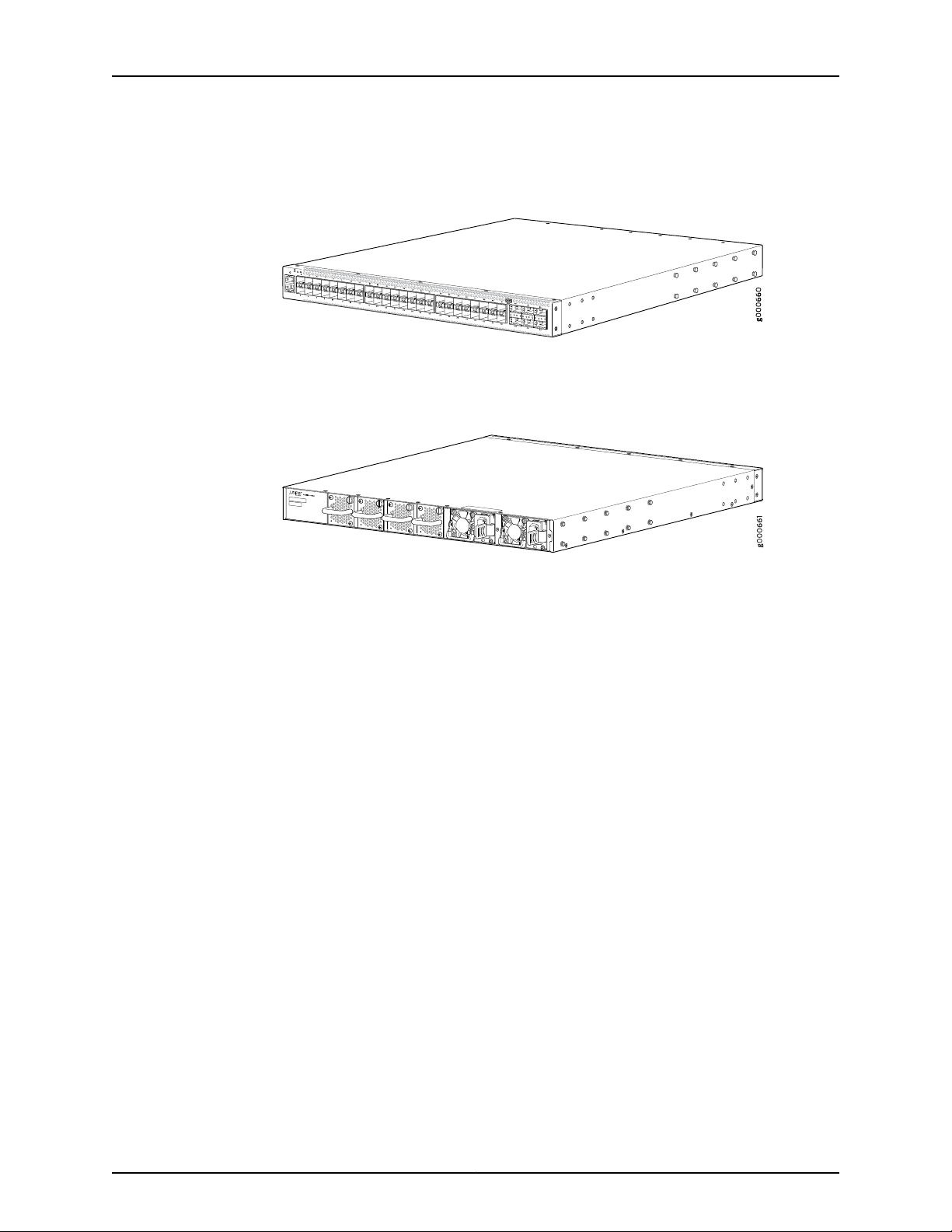
Figure 1 on page 4 shows the front panel of an OCX1100-48SX switch.
Figure 1: Front Panel of an OCX1100-48SX Switch
Figure 2 on page 4 shows the rear panel of an OCX1100-48SX switch with powersupplies
and fan modules installed.
Figure 2: Rear Panel of an OCX1100-48SX Switch
Power Supplies
To provide carrier-class reliability, OCX1100-48SX switches include:
•
Two fully redundant, load-sharing power supplies (either AC or DC) that are
hot-insertable and hot-removable field-replaceable units (FRUs).
•
Four redundant fan modules that are field-replaceable units.
•
Junos OS with its modular design that enables failed system processes to gracefully
restart.
OCX1100 switches support AC or DC power supplies with different airflow directions,
depending on the model. Power supplies for OCX1100 switches are fully redundant and
load-sharing, and theyare hot-removable and hot-insertable FRUs. The OCX1100-48SX
switches are shipped with two power supplies preinstalled in the rear panel of the
switches.
Each power supply has a label—AIR IN (AFI) or AIR OUT (AFO)—on the faceplate of the
power supply that indicates the direction of airflow. AIR IN (AFI) labels indicate
back-to-front airflow while AIR OUT (AFO) labels indicate front-to-back airflow.
Power supplies are installed in the two power supply slots located on the rear panel of
the switch.
Table 3 on page 5 lists the AC and DC power supplies used in OCX1100 switches and
the direction of airflow in them.
Copyright © 2017, Juniper Networks, Inc.4
Page 25

Table 3: Airflow Direction in Power Supply for OCX1100 Switches
Direction of AirflowLabel on Power SupplyPowerSupplyRating
Chapter 1: System Overview
AIR IN (AFI)460 W AC
AIR OUT (AFO)460 W AC
AIR IN (AFI)800 W DC
AIR OUT (AFO)800 W DC
Back-to-front—that is, air intake to cool the
chassis is through the vents on the rear panel of
the chassis and hot air exhausts through the vents
on the front panel of the chassis.
Front-to-back—that is, air intake to cool the
chassis is through the vents on the front panel of
the chassis and hot air exhausts through the vents
on the rear panel of the chassis.
For more information, see “Cooling System and Airflow in an OCX1100 Switches” on
page 17.
CAUTION: Do not install:
Fan Modules
•
AC and DC power supplies in the same chassis.
•
AC power supplies in DC switch models or DC power supplies in AC switch
models.
•
Power supplies with different airflow labels (AIR IN (AFI) and AIR OUT
(AFO)) in the same chassis.
•
Power supplies and fan modules with differentairflow labels (AIR IN (AFI)
and AIR OUT (AFO)) in the same chassis.
The fan modules in OCX1100 switches are hot-insertable and hot-removable
field-replaceable units (FRUs). OCX1100-48SX switches are shipped with four fan
modules preinstalled in the rear panel of the switch.
The fan modules are available in two models that have different airflow
directions—back-to-front airflow, indicated by the label AIR IN (AFI) and front-to-back
airflow, indicated by the label AIR OUT (AFO). See “Cooling System and Airflow in an
OCX1100 Switches” on page 17.
5Copyright © 2017, Juniper Networks, Inc.
Page 26
OCX1100 Switch Hardware Guide
CAUTION: Do not mix:
•
Fan modules with different airflow labels (AIR IN (AFI) and AIR OUT (AFO))
in the same chassis.
•
Fan modules and power supplies with different airflow labels (AIR IN (AFI)
and AIR OUT (AFO)) in the same chassis.
Fan modules are installed in the four fan module slots located on the rear panel of the
switch.
OCX1100-48SX Switch Components
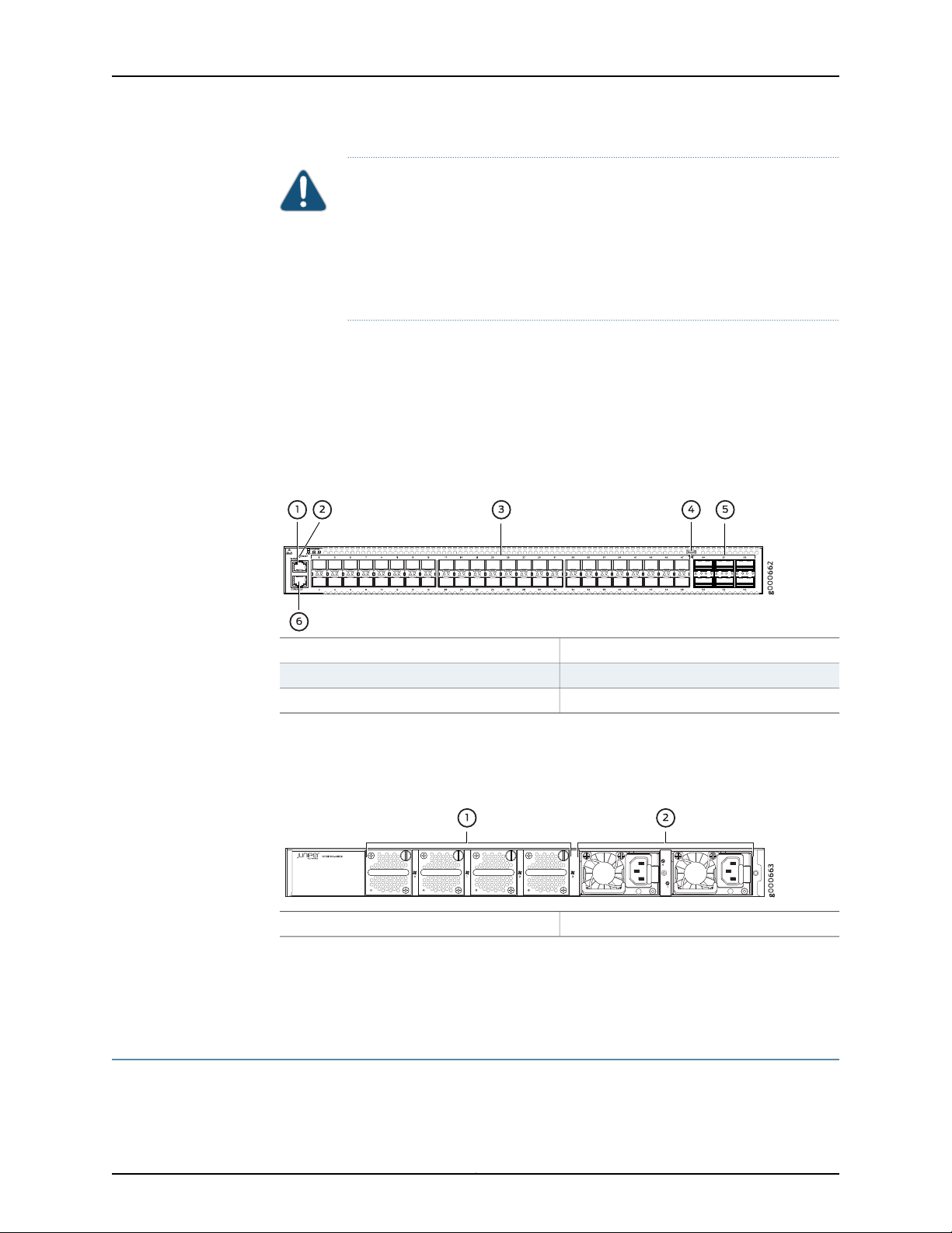
Figure 3 on page 6 shows the components on the front panel of an OCX1100-48SX
switch.
Figure 3: Components on the Front Panel of an OCX1100-48SX Switch
Figure 4 on page 6 shows the components on the rear panel of an OCX1100-48SX switch
(with two AC power supplies and four fan modules installed).
Figure 4: Components on the Rear Panel of an OCX1100-48SX Switch
Related
Documentation
OCX1100 Switch Models on page 6•
• Field-Replaceable Units in OCX1100 Switches on page 12
OCX1100 Switch Models
Table 4 on page 7 lists the components shipped with OCX1100-48SX switch models.
4—1— Mini-USB console portManagement port
5—2— QSFP+ portsRESET button
6—3— Console portSFP+ ports
2—1— Power suppliesFan modules
Copyright © 2017, Juniper Networks, Inc.6
Page 27

Chapter 1: System Overview
Table 4: OCX1100-48SXSwitchModels, Shipped Components, and Supported Junos OS Release
First Junos OS
ReleaseFan ModulesPower SupplyNumber and Types of PortsModel Number
OCX1100-48SX-AFO
OCX1100-48SX-AFI
OCX1100-48SX-D-AFO
OCX1100-48SX-D-AFI
Related
Documentation
48 10-Gigabit Ethernet SFP+
ports and 6 40-Gigabit Ethernet
QSFP+ ports
48 10-Gigabit Ethernet SFP+
ports and 6 40-Gigabit Ethernet
QSFP+ ports
48 10-Gigabit Ethernet SFP+
ports and 6 40-Gigabit Ethernet
QSFP+ ports
48 10-Gigabit Ethernet SFP+
ports and 6 40-Gigabit Ethernet
QSFP+ ports
Two 460 W AC power
supplies with the AIR OUT
(AFO) label.
Two 460 W AC power
supplies with the AIR IN (AFI)
label.
Two 800 W DC power
supplies with the AIR OUT
(AFO) label.
Two 800 W DC power
supplies with the AIR IN (AFI)
label.
NOTE: Transceivers are not part of the shipping configuration. If you want
topurchase transceivers,additional powersupplies, or additional fan modules
for your switch, you must order them separately.
Chassis Physical Specifications for OCX1100 Switches on page 11•
• OCX1100 Switches Hardware Overview on page 3
14.1X53-D20Four fan modules;
each with an AIR
OUT (AFO) label.
14.1X53-D20Four fan modules;
each with an AIR
IN (AFI) label.
14.1X53-D20Four fan modules;
each with an AIR
OUT (AFO) label.
14.1X53-D20Four fan modules;
each with an AIR
IN (AFI) label.
OCX1100 Switch Hardware and CLI Terminology Mapping
This topic describes the hardware terms used in OCX1100-48SX switch documentation
and the corresponding terms used in the Junos OS CLI. See Table 5 on page 7.
Table 5: CLI Equivalents of Terms Used in the Documentation for OCX1100-48SX Switches
Hardware
Item (CLI)
Chassis
•
OCX1100-48SX-AFO
•
OCX1100-48SX-AFI
•
OCX1100-48SX-D-AFO
•
OCX1100-48SX-D-AFI
Switch chassis–One of the following:
Additional InformationItem In DocumentationValueDescription (CLI)
“Chassis Physical
Specifications for
OCX1100 Switches” on
page 11
7Copyright © 2017, Juniper Networks, Inc.
Page 28

OCX1100 Switch Hardware Guide
Table 5: CLI Equivalents of Terms Used in the Documentation for OCX1100-48SX
Switches (continued)
Hardware
Item (CLI)
Additional InformationItem In DocumentationValueDescription (CLI)
Routing
Engine (n)
FPC (n)
PIC (n)
•
OCX1100-48SX-AFO
•
OCX1100-48SX-AFI
•
OCX1100-48SX-D-AFO
•
OCX1100-48SX-D-AFI
the Flexible PIC
Concentrator (FPC)
One of the following:
•
OCX1100-48SX-AFO
•
OCX1100-48SX-AFI
•
OCX1100-48SX-D-AFO
•
OCX1100-48SX-D-AFI
the Physical Interface
Card (PIC)
Value of n is always 0.One of the following:
–RE refers to the switch
itself.
Value of n is always 0.Abbreviated name of
–The switch does not have
actual FPCs. In this case,
FPC refers to the switch
itself.
–Value of n is always 0.Abbreviated name of
PIC 048x10G-6x40G
PIC 0 stands for the
built-in SFP+ and QSFP+
ports. In the CLI output,
“OCX1100 Switches
Hardware Overview” on
page 3
the SFP+ ports are
numbered 1 through 48
and the QSFP+ ports are
numbered 49 through 54.
Xcvr (n)
(n)
Abbreviated name of
the transceiver
•
OCX-460W-X-AC-AFI
•
OCX-460W-X-AC-AFO
•
OCX-800W-X-DC-AFI
•
OCX-800W-X-DC-AFO
Optical transceiversn is a value equivalent to
the number of the port in
which the transceiver is
“Pluggable Transceivers
Supported on OCX1100
Switches” on page 47
installed.
Value of n is always 0.One of the following:Power supply
AC power supply or DC
power supply
•
AC Power Supply in
OCX1100 Switches on
page 23
•
DC Power Supply in
OCX1100 Switches on
page 25
CAUTION: Do not install:
•
AC and DC power supplies in the same chassis.
•
AC power supplies in DC switch models or DC power supplies in AC switch models.
•
Power supplies with different airflow labels (AIR IN (AFI) and AIR OUT (AFO)) in
the same chassis.
•
Powersupplies and fan modules with different airflow labels (AIR IN (AFI) and AIR
OUT (AFO)) in the same chassis.
Copyright © 2017, Juniper Networks, Inc.8
Page 29

Chapter 1: System Overview
Table 5: CLI Equivalents of Terms Used in the Documentation for OCX1100-48SX
Switches (continued)
Hardware
Item (CLI)
Additional InformationItem In DocumentationValueDescription (CLI)
Fan tray
Documentation
One of the following:
•
OCX-FAN-X-AFI
•
OCX-FAN-X-AFO
Related
• OCX1100 Switches Hardware Overview on page 3
Fan modulen has a value 0, 1, 2, or 3
corresponding to the fan
module slot number.
“Cooling System and
Airflow in an OCX1100
Switches” on page 17
CAUTION: Do not mix:
•
Fan modules with different airflow labels (AIR IN (AFI) and AIR OUT (AFO)) in the
same chassis.
•
Powersupplies and fan modules with different airflow labels (AIR IN (AFI) and AIR
OUT (AFO)) in the same chassis.
9Copyright © 2017, Juniper Networks, Inc.
Page 30

OCX1100 Switch Hardware Guide
Copyright © 2017, Juniper Networks, Inc.10
Page 31

CHAPTER 2
Chassis Components and Descriptions
•
Chassis Physical Specifications for OCX1100 Switches on page 11
•
Field-Replaceable Units in OCX1100 Switches on page 12
•
Chassis Status LEDs on OCX1100 Switches on page 12
•
Management Port LEDs and Console Port LEDs on OCX1100 Switches on page 13
•
SFP+ Port and QSFP+ Port LEDs on OCX1100 Switches on page 14
Chassis Physical Specifications for OCX1100 Switches
The OCX1100 switch chassis is a rigid sheet-metal structure that houses all components
of the switch. Table 6 on page 11 summarizes the physical specifications of the
OCX1100-48SX switch chassis.
Table 6: Physical Specifications of the OCX1100-48SX Switch Chassis
ValueDescription
Related
Documentation
1.723 in. (4.39 cm)Chassis height
17.32 in. (43.99 cm)Chassis width
19.18 in. (48.71 cm)Chassis depth
(With two power supplies and four fan modules installed): 20 lb (9.71 kg)Weight
You can mount an OCX1100 switch on a standard 19-in. four-post rack. You can also
mount the switch in a standard 19-in. enclosed cabinet or on a desk or any level surface.
Rack Requirements on page 35•
• Cabinet Requirements on page 36
• Mounting an OCX1100 Switch on page 70
• Installing and Connecting an OCX1100 Switch on page 69
• Installing and Removing OCX1100 Switch Hardware Components on page 74
11Copyright © 2017, Juniper Networks, Inc.
Page 32

OCX1100 Switch Hardware Guide
Field-Replaceable Units in OCX1100 Switches
Field-replaceable units (FRUs) are components that you can replace at your site. The
FRUs in OCX1100 switches are hot-removable and hot-insertable: You can remove and
replace them without powering off the switch. The FRUs in OCX1100 switches are:
•
Power supplies
•
Fan modules
•
Transceivers
NOTE: Transceivers are not part of the shipping configuration. If you want
to purchase transceivers, additional power supplies, or fan modules for your
switch, you must order them separately.
NOTE: If you have a Juniper J-Care service contract, register any addition,
change, or upgrade of hardware components at
https://www.juniper.net/customers/support/tools/updateinstallbase/ . Failure
to do so can result in significant delays if you need replacement parts. This
note does not apply if you replace existing components with the same type
of component.
Related
Installing and Removing OCX1100 Switch Hardware Components on page 74•
Documentation
Chassis Status LEDs on OCX1100 Switches
An OCX1100 switch has four chassis status LEDs (labeled LOCATOR, STAT, PWR, and
FAN) on the left of the chassis, next to the RESET button (see Figure 5 on page 12).
Figure 5: Chassis Status LEDs in an OCX1100-48SX Switch
3—1— PWRSTAT
4—2— FANLOCATOR
Copyright © 2017, Juniper Networks, Inc.12
Page 33

Table 7 on page 13 describes the chassis status LEDs on an OCX1100-48SX switch, their
colors and states, and the status they indicate. You can view the colors of the four LEDs
directly on the chassis or remotely through the CLI by issuing the operational mode
command show chassis led.
Table 7: Chassis Status LEDs on an OCX1100-48SX Switch
State and DescriptionColorLED Label
•
BlueLOCATOR
GreenSTAT (Status)
Blinking—Locator function is enabled.
•
Off—Locator function is disabled.
Locator is used to show where the device is.
•
On steadily—POST (power-on self-test) passed. Normal operation.
•
Blinking—POST in progress.
•
Off—The switch is powered off or is halted.
Blinking—POST, power supply, or fan module failed. System too hot.Amber
Chapter 2: Chassis Components and Descriptions
•
GreenPWR (Power)
GreenFAN
On steadily—Power on.
•
Off—Power off. No power cable attached.
Blinking—One of the power supply failed.Amber
•
On steadily—Normal operation.
•
Off—Not receiving power.
Blinking—Fan failure.Amber
All four LEDs can be lit simultaneously.
Related
OCX1100 Switches Hardware Overview on page 3•
Documentation
Management Port LEDs and Console Port LEDs on OCX1100 Switches
The management port—labeled MGMT— and the console port—labeled CONSOLE— on
the front panel of an OCX1100 switch have two LEDs each that indicate link and activity
and status of the ports. The status LED on the management port and the link and activity
LED on the console port are inactive LEDs. Figure 6 on page 14 shows the location of
LEDs on the management port and the console port of an OCX1100-48SX switch.
13Copyright © 2017, Juniper Networks, Inc.
Page 34

OCX1100 Switch Hardware Guide
Figure 6: LEDs on the Management Port and Console Port on an
OCX1100-48SX Switch
2—1—
Status LED for CONSOLE portLink and activity LED for MGMT port
Table 8 on page 14 describes the link and activity LED on the management port.
Table 8: Link and Activity LED on the Management Port of an OCX1100-48SX Switch
State and DescriptionColorLED
•
GreenLink and activity
On steadily—The port and the link are active, but there is no link activity.
•
Blinking—The port and the link are active, and there is link activity.
•
Off—The port is not active.
Table 9 on page 14 describes the status LED on the console port.
Table 9: Status LED on the Console Port of an OCX1100-48SX Switch
State and DescriptionColorLED
•
GreenStatus
Related
Documentation
OCX1100 Switches Hardware Overview on page 3•
• Connecting a Device to a Network for Out-of-Band Management on page 85
On steadily—Console on.
•
Off—Console off.
SFP+ Port and QSFP+ Port LEDs on OCX1100 Switches
On an OCX1100 switch, each SFP+ port and QSFP+ port has one LED that shows the link
and activity of the port.
The following figures in this topic show the location of those LEDs:
•
Figure 7 on page 15 shows the location of the LEDs on the SFP+ ports.
•
Figure 8 on page 15 shows the location of the LEDs on the QSFP+ ports.
Copyright © 2017, Juniper Networks, Inc.14
Page 35

Figure 7: LEDs on SFP+ Ports
Figure 8: LEDs on QSFP+ Ports
Chapter 2: Chassis Components and Descriptions
2—1— Link and activity LED of the lower portLink and activity LED of the upper port
2—1— Link and activity LED of the lower portLink and activity LED of the upper port
Table 10 on page 15 describes the link and activity LED on SFP+ ports in OCX1100 switches.
Table 10: Link and Activity LED on SFP+ Ports
State and DescriptionColorLED
GreenLink and activity
Indicates the status. The status indicators are:
•
On steadily—Secure 10-Gbps connection is active.
•
Blinking—Packets transmitted and received.
•
Off—No active connection or port disabled.
Table 11 on page 15 describes the link and activity LED on QSFP+ ports in OCX1100
switches.
Table 11: Link/Activity LED on QSFP+ Ports
GreenLink and activity
State and DescriptionColorLED
Indicates the status. The status indicators are:
•
On steadily—Secure 40-Gbps connection is active.
•
Blinking—Packets transmitted and received.
•
Off—No active connection or port disabled.
Related
Documentation
• OCX1100 Switches Hardware Overview on page 3
15Copyright © 2017, Juniper Networks, Inc.
Page 36

OCX1100 Switch Hardware Guide
Copyright © 2017, Juniper Networks, Inc.16
Page 37

CHAPTER 3
Cooling System and Airflow
•
Cooling System and Airflow in an OCX1100 Switches on page 17
Cooling System and Airflow in an OCX1100 Switches
The cooling systemin an OCX1100-48SX switch consists of four fan modules and a single
fan in each power supply. OCX1100 switches provide back-to-front airflow (air enters
through the vents on the rear panel of the switch chassis), indicated by the label AIR IN
(AFI), or front-to-back (air exhausts through the vents on the rear panel of the switch
chassis), indicated by the label AIR OUT (AFO)—depending on the fan modules and
power supplies installed in the switch.
This topic describes:
•
Fan Modules on page 17
•
Airflow Direction in OCX1100-48SX Switch Models on page 18
•
Front-to-Back Airflow on page 19
•
Back-to-Front Airflow on page 20
•
Do Not Install AIR IN (AFI) and AIR OUT (AFO) Components in the Same
Chassis on page 21
•
Positioning the Switch on page 21
Fan Modules
The OCX1100 switches fan modules are hot-insertable and hot-removable
field-replaceable units (FRUs).
All OCX1100-48SX switches are shipped with four fan modules preinstalled in the rear
panel of the switch. Each switch can accommodate four fan modules in the fan module
slots on the rear panel of the switch. The fan module slots are numbered 0 through 3
and each slot has a fan icon next to it.
Figure 9 on page 18 shows the fan module used in an OCX1100 switch:
17Copyright © 2017, Juniper Networks, Inc.
Page 38

OCX1100 Switch Hardware Guide
Figure 9: Fan Module Used in an OCX1100 Switch
CAUTION: You must remove only one fan module at a time for replacement
from the rear panel of the chassis. The switch continues to operate without
thermal shutdown for a limited period of time (30 seconds) during the
replacement of a fan module.
NOTE: Four fan modules must be installed for optimal functioning of the
switch.
The fan modules are available in two models that have different airflow
directions—back-to-front (air enters through the vents on the rear panel of the switch
chassis), indicated by the label AIR IN (AFI), and front-to-back (air exhausts through the
vents on the rear panel of the switch chassis), indicated by the label AIR OUT (AFO).
Table 12 on page 18 lists the available fan module models and the direction of airflow in
them.
Table 12: Fan Modules in OCX1100-48SX Switches
Label on the Fan ModuleFan Module
AIR OUT (AFO)OCX-FAN-X-AFO
AIR IN (AFI)OCX-FAN-X-AFI
Airflow Direction in OCX1100-48SX Switch Models
Table 13 on page 18 shows the direction of airflow in OCX1100-48SX switch models as
shipped.
Table 13: Airflow Direction in OCX1100-48SX Switch Models
OCX1100-48SX-AFO
The switch ships with four fan modules and
two AC power supplies installed; all bearing
the label AIR OUT (AFO).
Direction of AirflowFan Modules and Power SupplyModel Number
Front-to-back—that is, air intake to cool the
chassisis through the vents on the front panel
of the chassis and hot air exhausts through
the vents on the rear panel of the chassis.
Copyright © 2017, Juniper Networks, Inc.18
Page 39

Chapter 3: Cooling System and Airflow
Table 13: Airflow Direction in OCX1100-48SX Switch Models (continued)
Direction of AirflowFan Modules and Power SupplyModel Number
OCX1100-48SX-D-AFO
OCX1100-48SX-AFI
OCX1100-48SX-D-AFI
The switch ships with four fan modules and
two DC power supplies installed; all bearing
the label AIR OUT (AFO).
The switch ships with four fan modules and
two AC power supplies installed; all bearing
the label AIR IN (AFI).
The switch ships with four fan modules and
two DC power supplies installed; all bearing
the label AIR IN (AFI).
Front-to-back—that is, air intake to cool the
chassisis through the vents on the front panel
of the chassis and hot air exhausts through
the vents on the rear panel of the chassis.
Back-to-front—that is, air intake to cool the
chassis is through the vents on the rear panel
of the chassis and hot air exhausts through
the vents on the front panel of the chassis.
Back-to-front—that is, air intake to cool the
chassis is through the vents on the rear panel
of the chassis and hot air exhausts through
the vents on the front panel of the chassis.
Figure 10 onpage 19 shows the locationof labels on the power supplies and fan modules
of an OCX1100-48SX switch.
Figure 10: Location of Airflow Labels on the Power Supplies and Fan
Modules of an OCX1100-48SX Switch
Front-to-Back Airflow
2—1— Airflow labels on the power suppliesAirflow labels on the fan modules
CAUTION: Do not install:
•
AC and DC power supplies in the same chassis.
•
AC power supplies in DC switch models or DC power supplies in AC switch
models.
•
Power supplies and fan modules with differentairflow labels (AIR IN (AFI)
and AIR OUT (AFO)) in the same chassis
•
Fan modules with different airflow labels (AIR IN (AFI) and AIR OUT (AFO))
in the same chassis.
In the OCX1100 switch models that have front-to-back airflow, the air intake to cool the
chassis is through the vents on the front panel of the switch and hot air exhausts through
the vents on the rear panel. See Figure 11 on page 20.
19Copyright © 2017, Juniper Networks, Inc.
Page 40

OCX1100 Switch Hardware Guide
Figure 11: Front-to-Back Airflow Through OCX1100-48SX Switch Chassis
Back-to-Front Airflow
You must install only power supplies that have AIR OUT (AFO) labels in switches in which
the fan modules have AIR OUT (AFO) labels.
In the OCX1100 switch models that have back-to-front airflow, the air intake to cool the
chassis is through the vents on the rear panel and hot air exhausts through the vents on
the front panel of the switch. See Figure 12 on page 20.
Figure 12: Back-to-Front Airflow Through the OCX1100-48SX Switch
Chassis
You must install only power supplies that have AIR IN (AFI) labels in switches in which
the fan modules have AIR IN (AFI) labels.
Copyright © 2017, Juniper Networks, Inc.20
Page 41

Chapter 3: Cooling System and Airflow
Do Not Install AIR IN (AFI) and AIR OUT (AFO) Components in the Same Chassis
Do not install power supplies and fan modules with different airflow labels (AIR IN (AFI)
and AIR OUT (AFO)) in the same chassis. If the fan modules have AIR IN (AFI) labels, the
powersupplies must also have AIR IN (AFI) labels; if the fan modules have AIR OUT (AFO)
labels, the power supplies must also have AIR OUT (AFO) labels.
The labels on the power supplies and fan modules should match the labels on the switch
chassis.
Mixing components with AIR IN (AFI) and AIR OUT (AFO) labels in the same chassis
hampers the performance of the cooling system of the switch and leads to overheating
of the chassis.
Under normal operating conditions, the fan modules operate at a moderate speed.
Temperature sensors in the chassis monitor the temperature within the chassis.
CAUTION: The system raises an alarm if a fan module fails or if the ambient
temperature inside the chassis rises above the acceptable range. If the
temperature inside the chassis rises above the threshold temperature, the
system shuts down automatically.
Positioning the Switch
Related
Documentation
In front-to-back airflow, indicated by the label AIR OUT (AFO) on the fan modules and
power supplies, hot air exhausts through the vents on the rear panel of the switch. In
back-to-front airflow, indicated by the label AIR IN (AFI) on the fan modules and power
supplies, hot air exhausts through the vents on the front panel of the switch.
In data center deployments, position the switch in such a manner that the AIR IN (AFI)
labels on switch components are next to the cold aisle, and AIR OUT (AFO) labels on
switch components are next to the hot aisle.
• OCX1100 Switches Hardware Overview on page 3
• Field-Replaceable Units in OCX1100 Switches on page 12
• Installing a Fan Module in an OCX1100 Switch on page 105
• Removing a Fan Module from an OCX1100 Switch on page 106
• Prevention of Electrostatic Discharge Damage on page 167
21Copyright © 2017, Juniper Networks, Inc.
Page 42

OCX1100 Switch Hardware Guide
Copyright © 2017, Juniper Networks, Inc.22
Page 43

CHAPTER 4
Power Supplies
•
AC Power Supply in OCX1100 Switches on page 23
•
DC Power Supply in OCX1100 Switches on page 25
•
Power Supply LEDs in OCX1100 Switches on page 27
AC Power Supply in OCX1100 Switches
The AC power supply in OCX1100 switches is a hot-insertable and hot-removable
field-replaceable unit (FRU): You can install it without powering off the switch or
disrupting switch functions.
All OCX1100-48SX switches that are powered by AC power supplies are shipped with
two AC power supplies preinstalled in the rear panel of the switches.
This topic describes the AC power supplies.
CAUTION: Do not install:
•
AC and DC power supplies in the same chassis.
•
AC power supplies in DC switch models or DC power supplies in AC switch
models.
•
Power supplies with different airflow labels (AIR IN (AFI) and AIR OUT
(AFO)) in the same chassis.
•
Power supplies and fan modules with differentairflow labels (AIR IN (AFI)
and AIR OUT (AFO)) in the same chassis.
This topic includes:
•
Characteristics of an AC Power Supply on page 23
Characteristics of an AC Power Supply
The AC power supplies for OCX1100 switches are available in two models:
OCX-460W-X-AC-AFO and OCX-460W-X-AC-AFI. Figure 13 on page 24 shows an AC
power supply for an OCX1100 switch. Both are 460 W models, one with AFO airflow and
the other with AFI airflow.
23Copyright © 2017, Juniper Networks, Inc.
Page 44

OCX1100 Switch Hardware Guide
Figure 13: AC Power Supply for an OCX1100 Switch
Table 14 on page 24 lists the details of the 460 W AC power supplies used in
OCX1100-48SX switches.
Table 14: Details of the AC Power Supplies in OCX1100-48SX Switches
460 W AC Power SupplyDetails
•
Model number
OCX-460W-X-AC-AFO
•
OCX-460W-X-AC-AFI
Power supply slots
NOTE: Each AC appliance inlet requires a
dedicated AC power feed.
Airflow
Hot-insertable and hot-removableField-replaceable unit (FRU) type
1.9 lb (0.861 kg)Power supply weight
2Minimum installed in chassis
2Maximum installed in chassis
Install in power supply slots labeled PSU 0 and PSU 1
in the rear panel of the chassis.
1NumberAC appliance Inlet
IEC-320-C13Type
2 ARating
InternalFans
•
Front-to-back, indicated by label AIR OUT (AFO)
•
Back-to-front, indicated by label AIR IN (AFI)
One bicolor LED.Power supply status LEDs
100–240 VACOperating range
To prevent electrical injury while installing or removing AC power supplies, carefully follow
instructions in “Installing an AC Power Supply in an OCX1100 Switch” on page 77 and
“Removing an AC Power Supply from an OCX1100 Switch” on page 111.
Copyright © 2017, Juniper Networks, Inc.24
Page 45

Chapter 4: Power Supplies
AC Power Supply Airflow
Each power supply has its own fan and is cooled by its own internal cooling system.
Each power supply has the label AIR OUT (AFO) or AIR IN (AFI) on the faceplate of the
power supply that indicates the direction of airflow in the power supply.
Table 15 on page 25 lists the AC power supply models and the direction of airflow in them.
Table 15: Airflow Direction in AC Power Supply Models for OCX1100-48SX Switches
Direction of AirflowLabel on PowerSupplyModel
Front-to-back—that is, air intake to cool the chassis is through the vents
on the front panel of the chassis and hot air exhausts through the vents
on the rear panel of the chassis.
Back-to-front—that is, air intake to cool the chassis is through the vents
on the rear panel of the chassis and hot air exhausts through the vents
on the front panel of the chassis.
Related
Documentation
AIR OUT (AFO)OCX-460W-X-AC-AFO
AIR IN (AFI)OCX-460W-X-AC-AFI
Power Supply LEDs in OCX1100 Switches on page 27•
• AC Power Supply Specifications for OCX1100 Switches on page 41
• Installing an AC Power Supply in an OCX1100 Switch on page 77
DC Power Supply in OCX1100 Switches
The DC power supply in OCX1100 switches is a hot-insertable and hot-removable
field-replaceable unit (FRU): You can install it without powering off the switch or
disrupting switch functions.
All OCX1100-48SX switches that are powered by DC power supplies are shipped with
two DC power supplies preinstalled in the rear panel of the switches.
This topic describes the DC power supplies.
CAUTION: Do not install:
•
AC and DC power supplies in the same chassis.
•
AC power supplies in DC switch models or DC power supplies in AC switch
models.
•
Power supplies with different airflow labels (AIR IN (AFI) and AIR OUT
(AFO)) in the same chassis.
•
Power supplies and fan modules with differentairflow labels (AIR IN (AFI)
and AIR OUT (AFO)) in the same chassis.
25Copyright © 2017, Juniper Networks, Inc.
Page 46

OCX1100 Switch Hardware Guide
This topic includes:
•
Characteristics of a DC Power Supply on page 26
Characteristics of a DC Power Supply
The DC power supplies for OCX1100 switches are available in two models;
OCX-800W-X-DC-AFI and OCX-800W-X-DC-AFO. Figure 14 on page 26 shows a DC
power supply for an OCX1100switch. Both are 800 W models, one with AFO airflow and
the other with AFI airflow.
Figure 14: DC Power Supply for an OCX1100 Switch
Table 16 on page 26 lists the details of the 800 W DC power supplies used in
OCX1100-48SX switches.
Table 16: Details of the DC Power Supplies in OCX1100-48SX Switches
800 W DC Power SupplyDetails
•
Model number
Power supply slots
Airflow
OCX-800W-X-DC-AFI
•
OCX-800W-X-DC-AFO
Hot-insertable and hot-removableField-replaceable unit (FRU) type
1.7 lb (0.771 kg)Power supply weight
2Minimum installed in chassis
2Maximum installed in chassis
Install in power supply slots labeled PSU 0 and PSU 1
in the rear panel of the chassis.
InternalFans
•
Front-to-back, indicated by label AIR OUT (AFO)
•
Back-to-front, indicated by label AIR IN (AFI)
One bicolor LED.Power supply status LED
–40.5 through –60 VDCOperating range
Copyright © 2017, Juniper Networks, Inc.26
Page 47

Chapter 4: Power Supplies
To prevent electrical injury while installing or removing DC powersupplies, carefullyfollow
instructions in “Installing a DC Power Supply in an OCX1100 Switch” on page 79 and
“Removing a DC Power Supply from an OCX1100 Switch” on page 114.
DC Power Supply Airflow
Each power supply has its own fan and is cooled by its own internal cooling system.
Each power supply has the label AIR OUT (AFO) or AIR IN (AFI) on the faceplate of the
power supply that indicates the direction of airflow in the power supply.
Table 17 on page27 lists the DC power supply models and the direction of airflow in them.
Table 17: Airflow Direction in AC Power Supply Models for OCX1100-48SX Switches
Direction of AirflowLabel on PowerSupplyModel
Front-to-back—that is, air intake to cool the chassis is through the vents
on the front panel of the chassis and hot air exhausts through the vents
on the rear panel of the chassis.
Back-to-front—that is, air intake to cool the chassis is through the vents
on the rear panel of the chassis and hot air exhausts through the vents
on the front panel of the chassis.
Related
Documentation
AIR OUT (AFO)OCX-800W-X-DC-AFO
AIR IN (AFI)OCX-800W-X-DC-AFI
Power Supply LEDs in OCX1100 Switches on page 27•
• DC Power Supply Specifications for OCX1100 Switches on page 44
• Installing a DC Power Supply in an OCX1100 Switch on page 79
Power Supply LEDs in OCX1100 Switches
Figure 15 on page 27 shows the location of the bicolor LED on an AC power supply for an
OCX1100 switch.
Figure 15: AC Power Supply LED in an OCX1100 Switch
1— Bicolor LED
27Copyright © 2017, Juniper Networks, Inc.
Page 48

OCX1100 Switch Hardware Guide
Figure 16 on page 28 shows the location of the bicolor LED on a DC power supply for an
OCX1100 switch.
Figure 16: DC Power Supply LED in an OCX1100 Switch
1— Bicolor LED
Table 18 on page 28 describes the power supply LED indications.
Table 18: Power Supply LED in OCX1100 Switches
Green
Amber
Documentation
Related
DescriptionLED Color
•
Blinking—Power present
•
On steadily—Output on and functioning normally
•
Off—No power
•
Blinking—Power supply warning events where the power supply continues to
operate: high temperature, high power, high current, slow fan.
•
On steadily—Powersupply critical event causing a shutdown: power supply failure,
overvoltage, overcurrent, overtemperature, fan failure, cord unplugged.
• AC Power Supply in OCX1100 Switches on page 23
• AC Power Supply Specifications for OCX1100 Switches on page 41
• Connecting AC Power to an OCX1100 Switch on page 80
• DC Power Supply in OCX1100 Switches on page 25
• DC Power Supply Specifications for OCX1100 Switches on page 44
• Connecting DC Power to an OCX1100 Switch on page 82
Copyright © 2017, Juniper Networks, Inc.28
Page 49

PART 2
Site Planning, Preparation, and
Specifications
•
Preparation Overview on page 31
•
Power Specifications and Requirements on page 41
•
Transceiver and Cable Specifications on page 47
•
Pinout Specifications on page 55
29Copyright © 2017, Juniper Networks, Inc.
Page 50

OCX1100 Switch Hardware Guide
Copyright © 2017, Juniper Networks, Inc.30
Page 51

CHAPTER 5
Preparation Overview
•
Site Preparation Checklist for OCX1100 Switches on page 31
•
Environmental Requirements and Specifications for OCX1100 Switches on page 32
•
General Site Guidelines on page 33
•
Site Electrical Wiring Guidelines on page 34
•
Chassis Physical Specifications for OCX1100 Switches on page 35
•
Requirements for Mounting an OCX1100 Switch on a Desktop or Other Level
Surface on page 35
•
Rack Requirements on page 35
•
Cabinet Requirements on page 36
•
Clearance Requirements for Airflow and Hardware Maintenance for OCX1100
Switches on page 37
Site Preparation Checklist for OCX1100 Switches
The checklist in Table 19 on page 31 summarizes the tasks you need to perform when
preparing a site for OCX1100 switch installation.
Table 19: Site Preparation Checklist
Environment
Verify that environmental factors such as
temperatureand humidity do not exceed switch
tolerances.
Power
Measure the distance between external power
sources and the switch installation site.
Calculate the power consumption and
requirements.
Hardware Configuration
“Environmental Requirements and
Specifications for OCX1100
Switches” on page 32
•
AC Power Supply Specifications
for OCX1100 Switches on page 41
•
DC Power Supply Specifications
forOCX1100 Switches on page 44
DatePerformed byFor More InformationItem or Task
31Copyright © 2017, Juniper Networks, Inc.
Page 52

OCX1100 Switch Hardware Guide
Table 19: Site Preparation Checklist (continued)
DatePerformed byFor More InformationItem or Task
Choose the number and types of switches you
want to install.
Rack or Cabinet
Verify that your rack or cabinet meets the
minimum requirements for the installation of
the switch.
Plan rack or cabinet location, including required
space clearances.
Secure the rack or cabinet to the floor and
building structure.
Cables
Acquire cables and connectors:
•
Determine the number of cables needed
based on your planned configuration.
•
Review the maximum distance allowed for
each cable. Choose the length of cablebased
on the distance between the hardware
components being connected.
Plan the cable routing and management.
“OCX1100 Switches Hardware
Overview” on page 3
•
Rack Requirements on page 35
•
Cabinet Requirementson page 36
“ClearanceRequirements for Airflow
and Hardware Maintenance for
OCX1100 Switches” on page 37
Related
Documentation
General Safety Guidelines and Warnings on page 137•
• General Site Guidelines on page 33
• Installing and Connecting an OCX1100 Switch on page 69
• Mounting an OCX1100 Switch on page 70
Environmental Requirements and Specifications for OCX1100 Switches
The switch must be installed in a rack or cabinet housed in a dry, clean, well-ventilated,
and temperature-controlled environment.
Ensure that these environmental guidelines are followed:
•
The site must be as dust-free as possible, because dust can clog air intake vents and
filters, reducing the efficiency of the switch cooling system.
•
Maintain ambient airflow for normal switch operation. If the airflow is blocked or
restricted, or if the intake air is too warm, the switch might overheat, leading to the
switch temperature monitor shutting down the switch to protect the hardware
components.
Copyright © 2017, Juniper Networks, Inc.32
Page 53

Table 20 on page 33 provides the required environmental conditions for normal switch
operation.
Table 20: OCX1100 Switch Environmental Tolerances
Environment Tolerance
Switch or
device TemperatureRelative HumidityAltitude
Chapter 5: Preparation Overview
OCX1100
switches
Documentation
No performance
degradation up to 9850
feet (3000 meters)
Related
Clearance Requirements for Airflowand HardwareMaintenance for OCX1100Switches
•
on page 37
General Site Guidelines
Efficient device operation requires proper site planning and maintenance and proper
layout of the equipment, rack or cabinet (if used), and wiring closet.
To plan and create an acceptable operating environment for your device and prevent
environmentally caused equipment failures:
Normal operation ensured in
relative humidity range of 0%
through 95% (noncondensing)
Normal operation ensured in the temperature
range 32° F through 104° F (0° C through
40° C) at altitudes up to 9850 ft (3000 m).
Nonoperating storage temperature range
–40° F (–40° C) through 158° F (70° C)
NOTE: Install OCX1100 switches only in restricted areas, such as dedicated
equipment rooms and equipment closets,in accordance with Articles110–16,
110–17, and 110–18 of the National Electrical Code, ANSI/NFPA 70.
Related
Documentation
•
Keep the area around the chassis free from dust and conductive material, such as
metal flakes.
•
Followprescribed airflow guidelines to ensure that the cooling systemfunctions properly
and that exhaust from other equipment does not blow into the intake vents of the
device.
•
Follow the prescribed electrostatic discharge (ESD) prevention procedures to prevent
damaging the equipment. Static discharge can cause components to fail completely
or intermittently over time.
•
Install the device in a secure area, so that only authorized personnel can access the
device.
Prevention of Electrostatic Discharge Damage on page 167•
33Copyright © 2017, Juniper Networks, Inc.
Page 54

OCX1100 Switch Hardware Guide
Site Electrical Wiring Guidelines
Table 21 on page 34 describes the factorsyou must consider while planning the electrical
wiring at your site.
WARNING: It is particularly important to provide a properly grounded and
shielded environment and to use electrical surge-suppression devices.
Table 21: Site Electrical Wiring Guidelines
GuidelinesSite Wiring Factor
Signaling limitations
Radio frequency interference
Electromagnetic compatibility
If your site experiences any of the following problems, consult
experts in electrical surge suppression and shielding:
•
Improperlyinstalledwirescause radio frequency interference
(RFI).
•
Damage from lightning strikes occurs when wires exceed
recommended distances or pass between buildings.
•
Electromagneticpulses (EMPs) caused by lightning damage
unshielded conductors and electronic devices.
To reduce or eliminateRFI from your site wiring, do the following:
•
Use a twisted-paircable with a good distribution of grounding
conductors.
•
If you must exceed the recommended distances, use a
high-quality twisted-pair cable with one ground conductor
for each data signal when applicable.
If your site is susceptible to problems with electromagnetic
compatibility (EMC), particularly from lightning or radio
transmitters, seek expert advice.
Some of the problems caused by strong sources of
electromagnetic interference (EMI) are:
•
Destruction of the signal drivers and receivers in the device
•
Electricalhazards as a result of power surges conductedover
the lines into the equipment
Related
Documentation
General Safety Guidelines and Warnings on page 137•
• General Electrical Safety Guidelines and Warnings on page 165
• Prevention of Electrostatic Discharge Damage on page 167
Copyright © 2017, Juniper Networks, Inc.34
Page 55

Chassis Physical Specifications for OCX1100 Switches
The OCX1100 switch chassis is a rigid sheet-metal structure that houses all components
of the switch. Table 6 on page 11 summarizes the physical specifications of the
OCX1100-48SX switch chassis.
Table 22: Physical Specifications of the OCX1100-48SX Switch Chassis
ValueDescription
1.723 in. (4.39 cm)Chassis height
17.32 in. (43.99 cm)Chassis width
19.18 in. (48.71 cm)Chassis depth
(With two power supplies and four fan modules installed): 20 lb (9.71 kg)Weight
Chapter 5: Preparation Overview
You can mount an OCX1100 switch on a standard 19-in. four-post rack. You can also
mount the switch in a standard 19-in. enclosed cabinet or on a desk or any level surface.
Related
Documentation
Rack Requirements on page 35•
• Cabinet Requirements on page 36
• Mounting an OCX1100 Switch on page 70
• Installing and Connecting an OCX1100 Switch on page 69
• Installing and Removing OCX1100 Switch Hardware Components on page 74
Requirements for Mounting an OCX1100 Switch on a Desktop or Other Level Surface
You can install OCX1100 switch on a desktop or other such level surface, by attaching
the four rubber feet (provided) to the bottom of the chassis.
When choosing a location, allow at least 6 in. (15.2 cm) of clearance between the front
and back of the chassis and adjacent equipment or walls.
Ensure that the desktop or other level surface on which the switch is installed is stable
and securely supported.
Related
Documentation
Clearance Requirements for Airflowand HardwareMaintenance for OCX1100Switches
•
on page 37
Rack Requirements
• Mounting an OCX1100 Switch on a Desk or Other Level Surface on page 70
You can mount the device on two-post racks or four-post racks.
35Copyright © 2017, Juniper Networks, Inc.
Page 56

OCX1100 Switch Hardware Guide
Rack requirements consist of:
•
Rack type
•
Mounting bracket hole spacing
•
Rack size and strength
•
Rack connection to the building structure
Table 23 on page 36 provides the rack requirements and specifications.
Table 23: Rack Requirements and Specifications
GuidelinesRack Requirement
Rack type
Mounting bracket hole spacing
Rack size and strength
Rack connection to building structure
You can mount the device on a rack that provides bracketholes or hole patterns spaced
at 1 U (1.75 in. or 4.45 cm) increments and meets the size and strength requirements to
support the weight.
A U is the standard rack unit defined in Cabinets, Racks, Panels, and Associated Equipment
(document number EIA-310–D) published by the Electronics Industry Association
(http://www.eia.org).
The holes in the mounting brackets are spaced at 1 U (1.75 in. or 4.45 cm), so that the
device can be mounted in any rack that provides holes spaced at that distance.
•
Ensure that the rack complies with the size and strength standards of a 19-in. rack as
defined in Cabinets, Racks, Panels, and Associated Equipment (document number
EIA-310–D) published by the ElectronicsIndustry Association (http://www.eia.org).
•
Ensure that the rack rails are spaced widely enough to accommodate the external
dimensions of the device chassis. The outer edges of the front-mounting brackets
extend the width of the chassis to 19 in. (48.2 cm).
•
The rack must be strong enough to support the weight of the device.
•
Ensure that the spacing of rails and adjacent racks provides for proper clearance
around the device and rack.
•
Secure the rack to the building structure.
•
If earthquakes are a possibility in your geographical area, secure the rack to the floor.
•
Secure the rack to the ceiling brackets as well as wall or floor brackets for maximum
stability.
Related
Documentation
Cabinet Requirements
You can mount the device in a cabinet that contains a 19-in. rack.
Cabinet requirements consist of:
•
•
Rack-Mounting and Cabinet-Mounting Warnings on page 148•
Cabinet size
Clearance requirements
Copyright © 2017, Juniper Networks, Inc.36
Page 57

•
Cabinet airflow requirements
Table 24 on page 37 provides the cabinet requirements and specifications.
Table 24: Cabinet Requirements and Specifications
Cabinet
Requirement
Cabinet size
Cabinet clearance
Guidelines
•
You can mount the device in a cabinet that contains a 19-in. rack as defined in Cabinets, Racks,
Panels, and Associated Equipment (document number EIA-310–D) published by the Electronics
Industry Association (http://www.ecianow.org/standards-practices/standards/).
•
The minimum cabinet size must be able to accommodate the maximum external dimensions of the
device.
•
The outer edges of the mounting brackets extend the width of the chassis to 19 in. (48.2 cm).
•
The minimum total clearance inside the cabinet is 30 in. (76.2 cm) between the inside of the front
door and the inside of the rear door.
Chapter 5: Preparation Overview
Cabinet airflow
requirements
When you mount the device in a cabinet, ensure that ventilation through the cabinet is sufficient to
prevent overheating.
•
Ensure adequate cool air supply to dissipate the thermal output of the device or devices.
•
Ensure that the hot air exhaust of the chassis exits the cabinet without recirculating into the device.
An open cabinet (without a top or doors) that employs hot air exhaust extraction from the top
ensures the best airflow through the chassis. If the cabinet contains a top or doors, perforations in
these elements assist with removing the hot air exhaust.
•
Install the device in the cabinet in a way that maximizes the open space on the side of the chassis
that has the hot air exhaust.
•
Route and dress all cables to minimize the blockage of airflow to and from the chassis.
•
Ensure that the spacing of rails and adjacent cabinets is such that there is proper clearance around
the device and cabinet.
•
A cabinet larger than the minimum required provides better airflow and reduces the chance of
overheating.
Related
Rack-Mounting and Cabinet-Mounting Warnings on page 148•
Documentation
Clearance Requirements for Airflowand Hardware Maintenance for OCX1100 Switches
When planning the site for installing an OCX1100 switch, you must ensure sufficient
clearance around the switch.
Follow these clearance requirements:
37Copyright © 2017, Juniper Networks, Inc.
Page 58

OCX1100 Switch Hardware Guide
•
For the cooling system to function properly, the airflow around the chassis must be
unrestricted. See Figure 17 on page 38 and Figure 18 on page 38 for reference.
Figure 17: Front-to-Back Airflow Through OCX1100-48SX Switch Chassis
Figure 18: Back-to-Front Airflow Through the OCX1100-48SX Switch
Chassis
•
If you are mounting the switch on a rack or cabinet along with other equipment,ensure
that the exhaust from other equipment does not blow into the intake vents of the
chassis.
•
Leave at least 6 in. (15.2 cm) clearance in front of and behind the chassis for airflow.
•
Leave at least 24 in. (60.9 cm) clearance in front of and behind the switch for service
personnel to remove and install hardware components. See Figure 19 on page 39.
Copyright © 2017, Juniper Networks, Inc.38
Page 59

Chapter 5: Preparation Overview
Figure 19: Clearance Requirements for Airflow and Hardware Maintenance
for an OCX1100-48SX Switch Chassis
Related
Documentation
• Chassis Physical Specifications for OCX1100 Switches on page 11
• Cooling System and Airflow in an OCX1100 Switches on page 17
• General Site Guidelines on page 33
• Rack-Mounting and Cabinet-Mounting Warnings on page 148
39Copyright © 2017, Juniper Networks, Inc.
Page 60

OCX1100 Switch Hardware Guide
Copyright © 2017, Juniper Networks, Inc.40
Page 61

CHAPTER 6
Power Specifications and Requirements
•
AC Power Supply Specifications for OCX1100 Switches on page 41
•
AC Power Cord Specifications for an OCX1100 Switch on page 41
•
DC Power Supply Specifications for OCX1100 Switches on page 44
AC Power Supply Specifications for OCX1100 Switches
OCX1100 switches support 460 W AC power supplies.
Table 25 on page 41 table lists the power supply specifications for AC power supplies
used in an OCX1100 switch:
Table 25: 460 W AC Power Supply Specifications for an OCX1100 Switch
SpecificationItem
•
AC input voltage
Low-voltage line: 100–120 VAC
•
High-voltage line: 200–240 VAC
50–60 HzAC input line frequency
•
AC input current rating
Related
Documentation
AC Power Supply in OCX1100 Switches on page 23•
• Power Supply LEDs in OCX1100 Switches on page 27
Low-voltage line: 4 A
•
High-voltage line: 2 A
460 WOutput power
AC Power Cord Specifications for an OCX1100 Switch
Each AC power supply has a single AC appliance inlet that requires a dedicatedAC power
feed. A detachable AC power cord is supplied with each AC power supply. The 460 W
ACpower supplies are shipped with AC power cordswith the C13 coupler type as described
by International Electrotechnical Commission (IEC) standard 60320. The plug at the
41Copyright © 2017, Juniper Networks, Inc.
Page 62

OCX1100 Switch Hardware Guide
male end of the power cord fits into the power source outlet that is standard for your
geographical location.
NOTE: In North America, AC power cords must not exceed 14.75 ft (4.5 m)
in length, to comply with National Electrical Code (NEC) Sections 400-8
(NFPA 75, 5-2.2) and 210-52 and Canadian Electrical Code (CEC) Section
4-010(3).
Table 26 on page 42 lists the AC power cords specifications provided for different power
supplies for each country or region.
Table 26: AC Power Cord Specifications for 460 W AC Power Supplies for an OCX1100 Switch
Country/
Region
Italy,
Switzerland,
and United
Kingdom)
Electrical
Specifications
250 VAC, 10 A, 50 HzChina
GraphicJuniper Model NumberPlug Standards
No graphic availableCBL-EX-PWR-C13-ARIRAM 2073 Type RA/3250 VAC, 10 A, 50 HzArgentina
CBL-EX-PWR-C13-AUAS/NZS 3112 TypeSAA/3250 VAC, 10 A, 50 HzAustralia
No graphic availableCBL-EX-PWR-C13-BRNBR 14136 Type BR/3250 VAC, 10 A, 50 HzBrazil
CBL-EX-PWR-C13-CHGB 1002-1996 Type
PRC/3
CBL-EX-PWR-C13-EUCEE (7) VII Type VIIG250 VAC, 10 A, 50 HzEurope (except
No graphic availableCBL-EX-PWR-C13-INIS 1293 Type IND/3250 VAC, 10 A, 50 HzIndia
Copyright © 2017, Juniper Networks, Inc.42
Page 63

g021274
g021289
Chapter 6: Power Specifications and Requirements
Table 26: AC Power Cord Specifications for 460 W AC Power Supplies for an OCX1100
Switch (continued)
Country/
Region
Japan
Korea
Electrical
Specifications
60 Hz
60 Hz
GraphicJuniper Model NumberPlug Standards
CBL-EX-PWR-C13-ILSI 32/1971 Type IL/3G250 VAC, 10 A, 50 HzIsrael
CBL-EX-PWR-C13-ITCEI 23-16 Type I/3G250 VAC, 10 A, 50 HzItaly
CBL-EX-PWR-C13-JPSS-00259 Type VCTF125 VAC, 12 A, 50 Hz or
CBL-EX-PWR-C13-KRCEE (7) VII Type VIIGK250 VAC, 10 A, 50 Hz or
CBL-EX-PWR-C13-USNEMA 5-15 Type N5-15125 VAC, 13 A, 60 HzNorth America
250 VAC, 10 A, 50 HzSouth Africa
ZA/3
CBL-EX-PWR-C13-SASABS 164/1:1992 Type
No graphic availableCBL-EX-PWR-C13-SZSEV 6534-2 Type 12G250 VAC, 10 A, 50 HzSwitzerland
43Copyright © 2017, Juniper Networks, Inc.
Page 64

g021288
OCX1100 Switch Hardware Guide
Table 26: AC Power Cord Specifications for 460 W AC Power Supplies for an OCX1100
Switch (continued)
Country/
Region
Kingdom
Documentation
Electrical
Specifications
Related
GraphicJuniper Model NumberPlug Standards
CBL-EX-PWR-C13-TWNEMA5-15P TypeN5-15P125 VAC, 10 A, 50 HzTaiwan
CBL-EX-PWR-C13-UKBS 1363/A Type BS89/13250 VAC, 10 A, 50 HzUnited
CAUTION: The AC power cord for the OCX1100 switch is intended for use
with this switch only. Do not use the cord with any other product.
CAUTION: Power cords must not block access to switch components.
AC Power Supply in OCX1100 Switches on page 23•
• Connecting AC Power to an OCX1100 Switch on page 80
• General Safety Guidelines and Warnings on page 137
• General Electrical Safety Guidelines and Warnings on page 165
• Prevention of Electrostatic Discharge Damage on page 167
DC Power Supply Specifications for OCX1100 Switches
OCX1100 switches support 800 W DC power supplies.
Table 27 on page 44 lists the power supply specifications for a DC power supply used in
an OCX1100 switch.
Table 27: DC Power Supply Specifications for an OCX1100 Switch
SpecificationsItem
•
DC input voltage
Nominal operating voltage: –40.5 VDC
•
Operating voltage range: –40.5 VDC through –60 VDC
4 A maximum at nominal operating voltage (–40.5 VDC)DC input current rating
800 WOutput power
Copyright © 2017, Juniper Networks, Inc.44
Page 65

Chapter 6: Power Specifications and Requirements
Related
Documentation
• DC Power Supply in OCX1100 Switches on page 25
• Power Supply LEDs in OCX1100 Switches on page 27
45Copyright © 2017, Juniper Networks, Inc.
Page 66

OCX1100 Switch Hardware Guide
Copyright © 2017, Juniper Networks, Inc.46
Page 67

CHAPTER 7
Transceiver and Cable Specifications
•
Pluggable Transceivers Supported on OCX1100 Switches on page 47
•
SFP+ Direct Attach Cables for OCX1100 Switches on page 50
•
Management Cable Specifications on page 53
Pluggable Transceivers Supported on OCX1100 Switches
This topic describes the optical interfaces supported for SFP+ and QSFP+ transceivers.
NOTE: We recommend that you use only optical transceivers and optical
connectors purchased from Juniper Networks with your Juniper Networks
device.
CAUTION: If you facea problem running a Juniper Networks device that uses
a third-party optic or cable, the Juniper NetworksTechnical Assistance Center
(JTAC) can help you diagnose the source of the problem. Your JTAC engineer
might recommend that you check the third-partyoptic or cable and potentially
replaceit with an equivalent Juniper Networks optic or cable that is qualified
for the device.
The 10-gigabit SFP+ and 40-gigabit QSFP+ transceivers installed in OCX1100 switches
support digital optical monitoring (DOM): You can view the diagnostic details for these
transceivers by issuing the operational mode CLI command show interfaces diagnostics
optics.
The tables in this topic describe the optical interfacesupport oversingle-mode fiber-optic
(SMF) and multimode fiber-optic (MMF) cables for SFP+ and QSFP+ transceivers:
•
Table 28 on page 48—Optical interface support for SFP+ transceivers.
•
Table 29 on page 50—Optical interface support for QSFP+ transceivers.
47Copyright © 2017, Juniper Networks, Inc.
Page 68

OCX1100 Switch Hardware Guide
Table 28: Optical Interface Support for SFP+ Transceivers in OCX1100 Switches
Ethernet
Standard
ValueSpecification
QFX-SFP-10GE-SRModel number10GBASE-SR
10 GbpsRate
LCConnector type
850 nmTransmitter wavelength
–7.3 dBmMinimum launch power
–1 dBmMaximum launch power
–9.9 dBmMinimum receiver sensitivity
–1 dBmMaximum input power
Core/Cladding size
Modal bandwidth
AvailableDOM support
MMFFiber type
62.5/125
µm
160
MHz/km
85 ft (26 m)Distance
62.5/125
µm
200
MHz/km
108 ft
(33 m)
50/125
µm
400
MHz/km
216 ft
(66 m)
50/125
µm
OM2–OM1FDDIFiber grade
500
MHz/km
269 ft
(82 m)
50/125
µm
OM3(OM4
compatible)
1500
MHz/km
984 ft
(300 m)
Copyright © 2017, Juniper Networks, Inc.48
Page 69

Chapter 7: Transceiver and Cable Specifications
Table 28: Optical Interface Support for SFP+ Transceivers in OCX1100 Switches (continued)
Ethernet
Standard
ValueSpecification
QFX-SFP-10GE-LRModel number10GBASE-LR
10 GbpsRate
LCConnector type
1310 nmTransmitter wavelength
–8.2 dBmMinimum launch power
0.5 dBmMaximum launch power
–18 dBmMinimum receiver sensitivity
0.5 dBmMaximum input power
SMFFiber type
9/125 µmCore/Cladding size
–Modal bandwidth
AvailableDOM support
6.2 miles (10 km)Distance
49Copyright © 2017, Juniper Networks, Inc.
Page 70

OCX1100 Switch Hardware Guide
Table 29: Optical Interface Support for QSFP+ Transceivers in OCX1100 Switches
Ethernet
Standard
ValueSpecification
QFX-QSFP-40G-SR4Model number40GBASE-SR4
40 GbpsRate
12-ribbon multimode fiber crossover cable with female MPO connectorsConnector type
12Fiber count
850 nmTransmitter wavelength
–7.6 dBm (per lane)Minimum launch power
2.4 dBm (per lane)Maximum launch power
–5.4 dBmMaximum receiversensitivity
4 dBmMaximum input power
AvailableDOM support
MMFFiber type
Related
Documentation
OCX1100 Switches Hardware Overview on page 3•
• Installing a Transceiver in an OCX1100 Switch
• Removing a Transceiver on page 119
SFP+ Direct Attach Cables for OCX1100 Switches
Small form-factor pluggable plus transceiver (SFP+) direct attach copper cables, also
known as Twinax cables, are suitable for in-rack connections between servers and
switches. They are suitable for short distances of up to 10 ft (3 m), making them ideal
for highly cost-effective networking connectivity within a rack and between adjacent
racks.
50/125 µm50/125 µmCore/Cladding size
OM4OM3Fiber grade
492 ft (150 m)328 ft (100 m)Distance
Copyright © 2017, Juniper Networks, Inc.50
Page 71

Chapter 7: Transceiver and Cable Specifications
This topic describes:
•
Cable Specifications on page 51
•
Standards Supported by These Cables on page 53
Cable Specifications
OCX1100 switches support SFP+ passive direct attach cables. The passive Twinax cable
is a straight cablewith no activeelectronic components. OCX1100 switches support cable
lengths of 3 ft (1 m) and 10 ft (3 m) long SFP+ passive direct attach cables.
Table 30 on page 51 describes the support for SFP+ passive direct attach cable lengths
on OCX1100 switches for Junos OS releases.
Table 30: Software Support for SFP+ Passive Direct Attach Cables for OCX1100 Switches
Cable LengthSoftware Support AddedSwitch
3 ft (1 m) and 10 ft (3 m)Junos OS Release 14.1X53-D20OCX1100-48SX-AFO
3 ft (1 m) and 10 ft (3 m)Junos OS Release 14.1X53-D20OCX1100-48SX-AFI
3 ft (1 m) and 10 ft (3 m)Junos OS Release 14.1X53-D20OCX1100-48SX-D-AFO
3 ft (1 m) and 10 ft (3 m)Junos OS Release 14.1X53-D20OCX1100-48SX-D-AFI
NOTE: Werecommendthatyou useonly SFP+ direct attach cables purchased
from Juniper Networks with your Juniper Networks device.
CAUTION: If you facea problem running a Juniper Networks device that uses
a third-party optic or cable, the Juniper NetworksTechnical Assistance Center
(JTAC) can help you diagnose the source of the problem. Your JTAC engineer
might recommend that you check the third-partyoptic or cable and potentially
replaceit with an equivalent Juniper Networks optic or cable that is qualified
for the device.
The cables are hot-removable and hot-insertable: You can remove and replace them
without powering off the switch or disrupting switch functions. A cable comprises a
low-voltage cable assembly that connects directly to two SFP+ ports, one at each end
of the cable. The cables use high-performance integrated duplex serial data links for
bidirectional communication and are designed for data rates of up to 10 Gbps.
Table 31 on page 52 describes the cable specifications.
51Copyright © 2017, Juniper Networks, Inc.
Page 72

OCX1100 Switch Hardware Guide
Table 31: SFP+ Direct Attach Cable Specifications
ValueSpecificationModel Number
10-Gbps full-duplex serial transmissionRateQFX-SFP-DAC-1M
Copper pigtailConnector type
3.3 VSupply voltage
0.015 WPower consumption (per end)
–40°C through 85°CStorage temperature
TwinaxCable type
30 AWGWire AWG
1 in. (2.54 cm)Minimum cable bend radius
100 ohmsCable characteristic impedance
1% maximumCrosstalk between pairs
4.3 nsec/mTime delay
3.3 ft (1 m)Length
Copper pigtailRateQFX-SFP-DAC-3M
SFP+ passive Twinax cable assemblyConnector type
3.3 VSupply voltage
0.015 WPower consumption (per end)
–40°C through 85°CStorage temperature
TwinaxCable type
30 AWGWire AWG
1 in. (2.54 cm)Minimum cable bend radius
100 ohmsCable characteristic impedance
1% maximumCrosstalk between pairs
4.3 nsec/mTime delay
9.9 ft (3 m)Length
Copyright © 2017, Juniper Networks, Inc.52
Page 73

Standards Supported by These Cables
The cables comply with the following standards:
•
SFP mechanical standard SFF-843—see ftp://ftp.seagate.com/sff/SFF-8431.PDF .
•
Electrical interface standard SFF-8432—see ftp://ftp.seagate.com/sff/SFF-8432.PDF .
•
SFP+ Multi-Source Alliance (MSA) standards.
Chapter 7: Transceiver and Cable Specifications
Related
Documentation
Pluggable Transceivers Supported on OCX1100 Switches on page 47•
• Installing a Transceiver in an OCX1100 Switch
• Removing a Transceiver on page 119
Management Cable Specifications
Table 32 on page 53 lists the specificationsfor the cables that connectthe console(CON)
and management (MGMT) ports to management devices.
Table 32: Specifications of Cables to Connect to Management Devices
RJ-45 Console (CON2) port
twisted pair) cable
Ethernet port (10/100/1000)
(CON1) port
RJ-45CAT5e UTP (unshielded
––Management (MGMT)
––Mini-USB Type-B Console
Additional InformationReceptacleCable SpecificationsPorts
“Connecting a Device to a
Management Console by
Using an RJ-45 Connector” on
page 86
“Connecting a Device to a
Network for Out-of-Band
Management” on page 85
53Copyright © 2017, Juniper Networks, Inc.
Page 74

OCX1100 Switch Hardware Guide
Copyright © 2017, Juniper Networks, Inc.54
Page 75

CHAPTER 8
Pinout Specifications
•
Console Port Connector Pinout Information on page 55
•
Mini-USB Port Pinout Specifications on page 56
•
RJ-45 Management Port Connector Pinout Information on page 56
•
RJ-45 to DB-9 Serial Port Adapter Pinout Information on page 57
•
RJ-45 Port, QSFP+ Port, SFP+ Port, and SFP Port Connector Pinout
Information on page 58
Console Port Connector Pinout Information
The console port on a Junier Networks device is an RS-232 serial interface that uses an
RJ-45 connector to connect to a console management device. The default baud rate for
the console port is 9600 baud.
Table 33 on page 55 provides the pinout information for the RJ-45 console connector.
NOTE: If your laptop or PC does not havea DB-9 male connectorpin and you
want to connect your laptop or PC directly to a device, use a combination of
the RJ-45 to DB-9 female adapter and a USB to DB-9 male adapter. You
must provide the USB to DB-9 male adapter.
Table 33: Console Port Connector Pinout Information
DescriptionSignalPin
Request to sendRTS Output1
Data terminal readyDTR Output2
Transmit dataTxD Output3
Signal groundSignal Ground4
Signal groundSignal Ground5
Receive dataRxD Input6
55Copyright © 2017, Juniper Networks, Inc.
Page 76

OCX1100 Switch Hardware Guide
Table 33: Console Port Connector Pinout Information (continued)
DescriptionSignalPin
Data carrier detectCD Input7
Clear to sendCTS Input8
Related
Documentation
Connectinga Deviceto a Management Console by Using an RJ-45Connectoron page86•
• Configuring the Console Port Type (CLI Procedure)
Mini-USB Port Pinout Specifications
If your management host (laptop or PC) does not have a DB-9 male connector pin or an
RJ-45 connector pin but has a USB port, you can connect your management host to the
Mini-USB Type-Bconsole port by using a cable that has a standard Type-A USB connector
on one end and a Mini-USB Type-B (5-pin) connector on the other end.
The Mini-USB Type-B console port uses a Mini-USB Type-B connector to connect to a
console management device. The default baud rate for the console port is 9600 baud.
Table 34 on page 56 provides the pinout information of the Mini-USB Type-B console
port.
Table 34: Mini-USB Type-B Console Port Pinout Information
DescriptionSignalPin
+5 VDCVCC1
Data -D-2
Data +D+3
N/CX
Related
Could be not connected (N/C), connected to ground (GND), or used as an attached device
presence indicator
GroundGND4
Management Cable Specifications on page 53•
Documentation
RJ-45 Management Port Connector Pinout Information
Table 35 on page 57 provides the pinout information for the RJ-45 connector for the
management port on Juniper Networks devices.
Copyright © 2017, Juniper Networks, Inc.56
Page 77

Table 35: RJ-45 Management Port Connector Pinout Information
DescriptionSignalPin
Transmit/receive data pair 1TRP1+1
Transmit/receive data pair 1TRP1-2
Transmit/receive data pair 2TRP2+3
Transmit/receive data pair 3TRP3+4
Transmit/receive data pair 3TRP3-5
Transmit/receive data pair 2TRP2-6
Transmit/receive data pair 4TRP4+7
Transmit/receive data pair 4TRP4-8
Chapter 8: Pinout Specifications
Related
Connecting a Device to a Network for Out-of-Band Management on page 85•
Documentation
RJ-45 to DB-9 Serial Port Adapter Pinout Information
The console port is an RS-232 serial interface that uses an RJ-45 connector to connect
to a management device such as a PC or a laptop. If your laptop or PC does not have a
DB-9 male connector pin and you want to connect your laptop or PC to the device, use
a combination of the RJ-45 to DB-9 female adapter along with a USB to DB-9 male
adapter.
Table 36 on page 57 provides the pinout information for the RJ-45 to DB-9 serial port
adapter.
Table 36: RJ-45 to DB-9 Serial Port Adapter Pinout Information
SignalDB-9 PinSignalRJ-45 Pin
CTS8RTS1
DSR6DTR2
RXD2TXD3
GND5GND4
TXD3RXD6
DTR4DSR7
57Copyright © 2017, Juniper Networks, Inc.
Page 78

OCX1100 Switch Hardware Guide
Table 36: RJ-45 to DB-9 Serial Port Adapter Pinout
Information (continued)
SignalDB-9 PinSignalRJ-45 Pin
RTS7CTS8
Related
Connectinga Deviceto a Management Console by Using an RJ-45Connectoron page86•
Documentation
RJ-45 Port, QSFP+ Port, SFP+ Port, and SFP Port Connector Pinout Information
Tables in this topic describe the connector pinout information for the RJ-45, QSFP+,
SFP+, and SFP ports.
•
Table 37 on page 58—10/100/1000BASE-T Ethernet network port connector pinout
information
•
Table 38 on page 59—SFP network port connector pinout information
•
Table 39 on page 59—SFP+ network port connector pinout information
•
Table 40 on page 60—QSFP+ network module port connector pinout information
Table 37: 10/100/1000BASE-T Ethernet Network Port Connector Pinout Information
DescriptionSignalPin
TRP1+1
TRP1-2
Transmit/receive data pair 1
Negative Vport (in PoE models)
Transmit/receive data pair 1
Negative Vport (in PoE models)
TRP2+3
TRP2-6
Transmit/receive data pair 2
Positive Vport (in PoE models)
Transmit/receive data pair 3TRP3+4
Transmit/receive data pair 3TRP3-5
Transmit/receive data pair 2
Positive Vport (in PoE models)
Transmit/receive data pair 4TRP4+7
Transmit/receive data pair 4TRP4-8
Copyright © 2017, Juniper Networks, Inc.58
Page 79

Table 38: SFP Network Port Connector Pinout Information
DescriptionSignalPin
Module transmitter groundVeeT1
Module transmitter faultTX_Fault2
Transmitter disabledTX_Disable3
2-wire serial interface data lineSDA4
2-wire serial interface clockSCL-5
Module absentMOD_ABS6
Rate selectRS7
Receiver loss of signal indicationRX_LOS8
Chapter 8: Pinout Specifications
Module receiver groundVeeR9
Module receiver groundVeeR10
Module receiver groundVeeR11
Receiver inverted data outputRD-12
Receiver noninverted data outputRD+13
Module receiver groundVeeR14
Module receiver 3.3 V supplyVccR15
Module transmitter 3.3 V supplyVccT16
Module transmitter groundVeeT17
Transmitter noninverted data inputTD+18
Transmitter inverted data inputTD-19
Module transmitter groundVeeT20
Table 39: SFP+ Network Port Connector Pinout Information
DescriptionSignalPin
Module transmitter groundVeeT1
Module transmitter faultTX_Fault2
59Copyright © 2017, Juniper Networks, Inc.
Page 80

OCX1100 Switch Hardware Guide
Table 39: SFP+ Network Port Connector Pinout Information (continued)
DescriptionSignalPin
Transmitter disabledTX_Disable3
2-wire serial interface data lineSDA4
2-wire serial interface clockSCL-5
Module absentMOD_ABS6
Rate select 0, optionally controls SFP+ module receiverRS07
Receiver loss of signal indicationRX_LOS8
Rate select 1, optionally controls SFP+ transmitterRS19
Module receiver groundVeeR10
Module receiver groundVeeR11
Receiver inverted data outputRD-12
Receiver noninverted data outputRD+13
Module receiver groundVeeR14
Module receiver 3.3 V supplyVccR15
Module transmitter 3.3 V supplyVccT16
Module transmitter groundVeeT17
Transmitter noninverted data inputTD+18
Transmitter inverted data inputTD-19
Module transmitter groundVeeT20
Table 40: QSFP+ Network Port Connector Pinout Information
SignalPin
GND1
TX2n2
TX2p3
GND4
Copyright © 2017, Juniper Networks, Inc.60
Page 81

Chapter 8: Pinout Specifications
Table 40: QSFP+ Network Port Connector Pinout Information (continued)
SignalPin
TX4n5
TX4p6
GND7
ModSelL8
LPMode_Reset9
VccRx10
SCL11
SDA12
GND13
RX3p14
RX3n15
GND16
RX1p17
RX1n18
GND19
GND20
RX2n21
RX2p22
GND23
RX4n24
RX4p25
GND26
ModPrsL27
IntL28
61Copyright © 2017, Juniper Networks, Inc.
Page 82

OCX1100 Switch Hardware Guide
Table 40: QSFP+ Network Port Connector Pinout Information (continued)
SignalPin
VccTx29
Vcc130
Reserved31
GND32
TX3p33
TX3n34
GND35
TX1p36
Related
Documentation
TX1n37
GND38
• Installing a Transceiver on page 117
Copyright © 2017, Juniper Networks, Inc.62
Page 83

PART 3
Initial Installation and Configuration
•
Unpacking the Switch on page 65
•
Installing the Switch on page 69
•
Connecting the Switch to Power on page 77
•
Connecting the Switch to the Network on page 85
•
Initially Configuring the Switch on page 91
63Copyright © 2017, Juniper Networks, Inc.
Page 84

OCX1100 Switch Hardware Guide
Copyright © 2017, Juniper Networks, Inc.64
Page 85

CHAPTER 9
Unpacking the Switch
•
Unpacking an OCX1100 Switch on page 65
•
Parts Inventory (Packing List) for an OCX1100 Switch on page 66
•
Registering Products—Mandatory for Validating SLAs on page 67
Unpacking an OCX1100 Switch
OCX1100 switches are shipped in a cardboard carton, securedwith foam packing material.
The carton has an accessory compartment and contains the quick start instructions.
CAUTION: OCX1100 switches are maximally protected inside the shipping
carton. Do not unpack the switches until you are ready to begin installation.
To unpack the switch:
1. Move the shipping carton to a staging area as close to the installation site as possible,
but where you have enough room to remove the system components.
Related
Documentation
2. Position the carton so that the arrows are pointing up.
3. Open the top flaps on the shipping carton.
4. Pull out the packing material holding the switch in place.
5. Verify the parts received against the inventory on the label attached to the carton.
See “Parts Inventory (Packing List) for an OCX1100 Switch” on page 66.
6. Save the shipping carton and packing materials in case you need to move or ship the
switch later.
Installing and Connecting an OCX1100 Switch on page 69•
• Connecting and Configuring an OCX1100 Switch (CLI Procedure) on page 100
65Copyright © 2017, Juniper Networks, Inc.
Page 86

OCX1100 Switch Hardware Guide
Parts Inventory (Packing List) for an OCX1100 Switch
The switch shipment includes a packing list. Check the parts you receive with the switch
against the items on the packing list. The packing list specifies the part number and
provides a description of each part in your order.The parts shipped depend on the switch
model you order. See “OCX1100 Switch Models” on page 6 for more information.
If any part on the packing list is missing, contact your customer service representative or
contact Juniper customer care from within the U.S. or Canada by telephone at
1-888-314-5822. For international-dial or direct-dial options in countries without toll-free
numbers, see http://www.juniper.net/support/requesting-support.html .
Table 41 on page 66 lists the parts and their quantities as in the standard packing list for
an OCX1100 switch.
Table 41: Inventory of Components Provided with an OCX1100-48SX Switch
Component
(appropriate for your
geographical location) or
DC power cords
brackets
bracket screws
DB-9 serial port adapter
Quantity
1Switch
4Fan modules
2 (AC or DC)Power supplies
2AC power cords
2Mounting brackets
2Rack-mounting slider
8Front rack mounting
4Rubber feet
1RJ-45 cable and RJ-45 to
AM 150MM BLK
instructions
Warranty
1CABLE USB2.0 AF-MICOR
1Quick Start installation
1Juniper Networks Product
Copyright © 2017, Juniper Networks, Inc.66
Page 87

Chapter 9: Unpacking the Switch
Table 41: Inventory of Components Provided with an OCX1100-48SX Switch (continued)
Component
Agreement
Quantity
1End User License
NOTE: You must provide the appropriate mounting screws for mounting the
switch on a rack or a cabinet.
Related
Documentation
OCX1100 Switches Hardware Overview on page 3•
• Unpacking an OCX1100 Switch on page 65
Registering Products—Mandatory for Validating SLAs
Registerall new Juniper Networks hardware products and changes to an existinginstalled
product using the Juniper Networks website to activate your hardware replacement
service-level agreements (SLAs).
CAUTION: Register product serial numbers on the JuniperNetworks website
and update the installation base data if there is any addition or change to
the installation base or if the installation base is moved. Juniper Networks
will not be held accountable for not meeting the hardware replacement
service-level agreement for products that do not have registered serial
numbers or accurate installation base data.
Related
Documentation
Registeryourproduct(s) at:https://tools.juniper.net/svcreg/SRegSerialNum.jsp.
Update your install base at:
https://www.juniper.net/customers/csc/management/updateinstallbase.jsp .
• Contacting Customer Support to Obtain Return Material Authorization on page 130
• Contacting Customer Support to Obtain a Return Materials Authorization for an NFX250
Device
67Copyright © 2017, Juniper Networks, Inc.
Page 88

OCX1100 Switch Hardware Guide
Copyright © 2017, Juniper Networks, Inc.68
Page 89

CHAPTER 10
Installing the Switch
•
Installing and Connecting an OCX1100 Switch on page 69
•
Mounting an OCX1100 Switch on page 70
•
Mounting an OCX1100 Switch on a Desk or Other Level Surface on page 70
•
Mounting an OCX1100 Switch on Four Posts of a Rack or Cabinet on page 71
•
Installing and Removing OCX1100 Switch Hardware Components on page 74
Installing and Connecting an OCX1100 Switch
To install and connect an OCX1100 switch:
1. Follow instructions in “Unpacking an OCX1100 Switch” on page 65.
2. Mount the switch by following the instructions appropriate for your site:
•
Mounting an OCX1100 Switch on a Desk or Other Level Surface on page 70
•
Mounting an OCX1100 Switch on Four Posts of a Rack or Cabinet on page 71
3. Follow instructions for connecting power as appropriate for your site:
•
Connecting AC Power to an OCX1100 Switch on page 80
•
Connecting DC Power to an OCX1100 Switch on page 82
4. Register your product by following instructions in “Registering Products—Mandatory
for Validating SLAs” on page 67.
5. Perform initial configuration of the switch by following the instructions in “Connecting
and Configuring an OCX1100 Switch (CLI Procedure)” on page 100.
6. Set the switch’s management options by following the instructions in:
•
Connecting a Device to a Network for Out-of-Band Management on page 85
•
Connecting a Device to a Management Console by Using an RJ-45 Connector on
page 86
•
Connecting an OCX1100 Switch to a Management Console by Using the Mini-USB
Type-B Console Port on page 87
69Copyright © 2017, Juniper Networks, Inc.
Page 90

OCX1100 Switch Hardware Guide
Related
Documentation
Rack Requirements on page 35•
• Cabinet Requirements on page 36
• ClearanceRequirementsfor Airflow and Hardware Maintenance forOCX1100 Switches
on page 37
Mounting an OCX1100 Switch
You can mount an OCX1100 switch:
•
On a desk or other level surface by using the rubber feet provided with the switch.
•
On four posts of a 19-in. rack or a 19-in. cabinet by using the mounting bracketsprovided
with the switch.
The holes in the mounting brackets are placed at 1 U (1.75 in. or 4.45 cm) apart so that
the switch can be mounted in any rack or cabinet that provides holes spaced at that
distance.
Related
Documentation
Mounting an OCX1100 Switch on a Desk or Other Level Surface on page 70•
• Mounting an OCX1100 Switch on Four Posts of a Rack or Cabinet on page 71
Mounting an OCX1100 Switch on a Desk or Other Level Surface
You can mount an OCX1100 switch on a desk or other level surface by using the four
rubber feet that are shipped with the switch. The rubber feet stabilize the chassis.
Before mounting the switch on a desk or other level surface:
•
Verify that the site meets the requirements described in “Site Preparation Checklist
for OCX1100 Switches” on page 31.
•
Place the desk in its permanent location, allowing adequate clearance for airflow and
maintenance, and secure it to the building structure.
•
Read “General Safety Guidelines and Warnings” on page 137, with particular attention
to “Chassis Lifting Guidelines” on page 146.
Ensure that you have the following parts and tools available:
•
Four rubber feet to stabilize the chassis on the a desk or other level surface (provided
in the accessory box in the switch carton)
To mount a switch on a desk or other level surface:
1. Remove the switch from the shipping carton (see “Unpacking an OCX1100 Switch”
on page 65).
2. Turn the chassis upside down on the desk or the level surface where you intend to
mount the switch.
Copyright © 2017, Juniper Networks, Inc.70
Page 91

Chapter 10: Installing the Switch
3. Attach the rubber feet to the bottom of the chassis, as shown in Figure 20 on page 71.
4. Turn the chassis right side up on the desk or the level surface.
Figure 20: Attaching Rubber Feet to the Switch Chassis
Related
Documentation
Connecting AC Power to an OCX1100 Switch on page 80•
• Connecting DC Power to an OCX1100 Switch on page 82
• Connecting and Configuring an OCX1100 Switch (CLI Procedure) on page 100
• ClearanceRequirementsfor Airflow and Hardware Maintenance forOCX1100 Switches
on page 37
Mounting an OCX1100 Switch on Four Posts of a Rack or Cabinet
You can mount an OCX1100 switch on four posts of a 19-in. rack or a 19-in. cabinet by
using the mounting brackets provided with the switch. (The remainder of this topic uses
rack to mean rack or cabinet.)
Before mounting the switch on four posts of a rack:
•
Verify that the site meets the requirements described in “Site Preparation Checklist
for OCX1100 Switches” on page 31.
•
Place the rack in its permanent location, allowing adequate clearance for airflow and
maintenance, and secure it to the building structure.
•
Read “General Safety Guidelines and Warnings” on page 137, with particular attention
to “Chassis Lifting Guidelines” on page 146.
•
Remove the switch from the shipping carton (see “Unpacking an OCX1100 Switch” on
page 65).
Ensure that you have the following parts and tools available:
•
Phillips (+) screwdriver (not provided)
•
Eight Phillips-head front rack-mounting bracket screws (provided)
•
Eight rack-mounting screws to secure the front rack-mounting brackets and the
rack-mounting slider brackets to the chassis (not provided)
•
One pair of front rack-mounting brackets (provided)
•
One pair of rack-mounting slider brackets (provided)
71Copyright © 2017, Juniper Networks, Inc.
Page 92

OCX1100 Switch Hardware Guide
NOTE: One person must be availableto lift the switch while another secures
it to the rack.
CAUTION: If you are mounting multiple units on a rack, mount the heaviest
unit at the bottom of the rack and mount the other units from the bottom of
the rack to the top in decreasing order of the weight of the units.
To mount the switch on four posts of a rack:
1. Place the switch on a flat, stable surface.
2. Align the holes on the front rack-mounting brackets with the screw holes on the side
of the chassis and attach the front rack-mounting brackets to the switch by using the
front rack-mounting bracket screws. See Figure 21 on page 72.
Figure 21: Attaching the Front Rack-Mounting Brackets to the Switch
Chassis
3. Align the holes on the rack-mounting slider brackets with the screw holes on the back
of the rack posts.
4. Attach the rack-mounting slider brackets to the rack posts by using appropriate
rack-mounting screws. Tighten the screws by using a screwdriver. See
Figure 22 on page 73.
NOTE: The ears of the rack-mounting slider brackets must be facing
backward and outward.
Copyright © 2017, Juniper Networks, Inc.72
Page 93

Chapter 10: Installing the Switch
Figure 22: Attaching the Rack-Mounting Slider Brackets to the Rack Posts
5. Position the switch so thatthe rack-mounting slider brackets align horizontally within
the two rows of rack-mounting slider bracket pegs located on the side panel of the
switch.
6. Slide the switch into the rack-mounting slider brackets so that the brackets fit into
the space between the two rows of rack-mounting slider pegs of the switch.
7. Have a second person secure the front rack-mounting brackets to the front of the
rack posts by using appropriate rack-mounting screws. Tighten the screws by using
a screwdriver. See Figure 23 on page 74.
73Copyright © 2017, Juniper Networks, Inc.
Page 94

g000667
OCX1100 Switch Hardware Guide
Figure 23: Sliding the Switch into Rack-Mounting Slider Brackets and
Mounting the Switch to the Front Posts of the Rack
8. Ensure that the switch chassis is level by verifying that all the screws on the front of
the rack are aligned with the screws at the back of the rack.
NOTE: We recommend that you install cover panels in unused fan modules
and power supply slots.
Related
Documentation
Connecting AC Power to an OCX1100 Switch on page 80•
• Connecting DC Power to an OCX1100 Switch on page 82
• Connecting and Configuring an OCX1100 Switch (CLI Procedure) on page 100
• Rack-Mounting and Cabinet-Mounting Warnings on page 148
Installing and Removing OCX1100 Switch Hardware Components
The OCX1100 switch chassis is a rigid sheet-metal structure that houses the hardware
components. The field-replaceable units (FRUs) in OCX1100 switches are:
•
Power supplies
•
Fan modules
•
Transceivers
The power supplies (AC or DC), fan modules, and transceivers are hot-removable and
hot-insertable: You can remove and replace them without powering off the switch or
disrupting switch functions.
Copyright © 2017, Juniper Networks, Inc.74
Page 95

Chapter 10: Installing the Switch
CAUTION: You must remove only one fan module at a time for replacement
from the rear panel of the chassis. The switch continues to operate without
thermal shutdown for a limited period of time (30 seconds) during the
replacement of a fan module.
See these topics for instructions for installing and removing components:
•
Installing an AC Power Supply in an OCX1100 Switch on page 77
•
Removing an AC Power Supply from an OCX1100 Switch on page 111
•
Installing a DC Power Supply in an OCX1100 Switch on page 79
•
Removing a DC Power Supply from an OCX1100 Switch on page 114
•
Installing a Fan Module in an OCX1100 Switch on page 105
•
Removing a Fan Module from an OCX1100 Switch on page 106
•
Installing a Transceiver in an OCX1100 Switch
Related
Documentation
•
Removing a Transceiver on page 119
• Cooling System and Airflow in an OCX1100 Switches on page 17
• AC Power Supply in OCX1100 Switches on page 23
• DC Power Supply in OCX1100 Switches on page 25
• Pluggable Transceivers Supported on OCX1100 Switches on page 47
75Copyright © 2017, Juniper Networks, Inc.
Page 96

OCX1100 Switch Hardware Guide
Copyright © 2017, Juniper Networks, Inc.76
Page 97

CHAPTER 11
Connecting the Switch to Power
•
Installing an AC Power Supply in an OCX1100 Switch on page 77
•
Installing a DC Power Supply in an OCX1100 Switch on page 79
•
Connecting AC Power to an OCX1100 Switch on page 80
•
Connecting DC Power to an OCX1100 Switch on page 82
Installing an AC Power Supply in an OCX1100 Switch
The AC power supply in OCX1100 switches is a hot-removable and hot-insertable
field-replaceable unit (FRU) installed in the rear panel of the switch: You can remove
and replace it without powering off the switch or disrupting switch functions.
CAUTION: Do not install:
•
AC and DC power supplies in the same chassis.
•
AC power supplies in DC switch models or DC power supplies in AC switch
models.
•
Power supplies with different airflow labels (AIR IN (AFI) and AIR OUT
(AFO)) in the same chassis.
•
Power supplies and fan modules with differentairflow labels (AIR IN (AFI)
and AIR OUT (AFO)) in the same chassis.
Before you install an AC power supply in the switch:
•
Ensure you understand how to prevent electrostatic discharge (ESD) damage. See
“Prevention of Electrostatic Discharge Damage” on page 167.
Ensure that you have the following parts and tools available to install the power supply:
•
ESD grounding strap
•
Phillips (+) screwdriver
77Copyright © 2017, Juniper Networks, Inc.
Page 98

OCX1100 Switch Hardware Guide
NOTE: Each power supply must be connected to a dedicated power source
outlet.
To install an AC power supply in the switch:
1. Ensure that you have the correct power supply. The label AIR IN (AFI) or AIR OUT
(AFO) on the power supply must match the label AIR IN (AFI) or AIR OUT (AFO) on
the installed fan module.
2. Attach the ESD grounding strap to your bare wrist, and connect the strap to the ESD
point on the chassis.
3. If the power supply slot has a cover panel on it,loosen the captive screws on the cover
panel by using your fingers or a screwdriver. Hold the captive screw and gently pull it
outward to remove the cover panel. Save the cover panel for later use.
4. Taking care not to touch power supply pins, leads, or solder connections, remove the
power supply from the bag.
5. Using both hands, place the power supply in the power supply slot on the rear panel
of the switch and slide it in until it is fully seated and the clip clicks into place. See
Figure 24 on page 78.
Figure 24: Installing an AC Power Supply in an OCX1100-48SX Switch
NOTE: If you have a Juniper J-Care service contract, register any addition,
change, or upgrade of hardware components at
https://www.juniper.net/customers/support/tools/updateinstallbase/ . Failure
to do so can result in significant delays if you need replacement parts. This
note does not apply if you replace existing components with the same type
of component.
Related
Documentation
Removing an AC Power Supply from an OCX1100 Switch on page 111•
• AC Power Supply in OCX1100 Switches on page 23
Copyright © 2017, Juniper Networks, Inc.78
Page 99

• AC Power Cord Specifications for an OCX1100 Switch on page 41
• Connecting AC Power to an OCX1100 Switch on page 80
• OCX1100 Switches Hardware Overview on page 3
Installing a DC Power Supply in an OCX1100 Switch
The DC power supply in OCX1100 switches is a hot-removable and hot-insertable
field-replaceable unit (FRU) installed in the rear panel of the switch: You can remove
and replace it without powering off the switch or disrupting switch functions.
CAUTION: Do not install:
•
AC and DC power supplies in the same chassis.
•
AC power supplies in DC switch models or DC power supplies in AC switch
models.
Chapter 11: Connecting the Switch to Power
•
Power supplies with different airflow labels (AIR IN (AFI) and AIR OUT
(AFO)) in the same chassis.
•
Power supplies and fan modules with differentairflow labels (AIR IN (AFI)
and AIR OUT (AFO)) in the same chassis.
Before you install a DC power supply in the switch:
•
Ensure you understand how to prevent electrostatic discharge (ESD) damage. See
“Prevention of Electrostatic Discharge Damage” on page 167.
Ensure that you have the following parts and tools available to install a DC power supply
in the switch chassis:
•
ESD grounding strap
•
Phillips (+) screwdriver
NOTE: Each power supply must be connected to a dedicated power source
outlet.
To install a DC power supply in the switch:
1. Ensure that you have the correct power supply. The label AIR IN (AFI) or AIR OUT
(AFO) on the power supply must match the label AIR IN (AFI) or AIR OUT (AFO) on
the installed fan module.
2. Attach the ESD grounding strap to your bare wrist, and connect the strap to the ESD
point on the chassis.
79Copyright © 2017, Juniper Networks, Inc.
Page 100

OCX1100 Switch Hardware Guide
3. If the power supply slot has a cover panel on it,loosen the captive screws on the cover
panel by using your fingers or the screwdriver. Hold the captive screw and gently pull
it outward to remove the cover panel. Save the cover panel for later use.
4. Taking care not to touch power supply pins, leads, or solder connections, remove the
power supply from the bag.
5. Using both hands, place the power supply in the power supply slot on the rear panel
of the switch and slide it in until it is fully seated and the clip clicks into place. See
Figure 25 on page 80
Figure 25: Installing a DC Power Supply in an OCX1100-48SX Switch
NOTE: If you have a Juniper J-Care service contract, register any addition,
change, or upgrade of hardware components at
https://www.juniper.net/customers/csc/management/updateinstallbase.jsp .
Failureto do so can resultin significant delays if you need replacement parts.
This note applies if you change the type of power supply or add a new type
of uplink module. It does not apply if you replacethese components with the
same type of component.
Related
Documentation
Removing a DC Power Supply from an OCX1100 Switch on page 114•
• DC Power Supply in OCX1100 Switches on page 25
• Connecting DC Power to an OCX1100 Switch on page 82
• OCX1100 Switches Hardware Overview on page 3
Connecting AC Power to an OCX1100 Switch
The AC-poweredmodels of (see “OCX1100 Switch Models” on page6) OCX1100 switches
support 460 W AC power supplies. After you install at least one power supply, you can
connect power to the switch.
CAUTION: Do not install:
Copyright © 2017, Juniper Networks, Inc.80
 Loading...