

Page 1

NorthStar Controller/Planner Getting
Published
2021-04-22
Started Guide
Release
6.1.0
Page 2

Juniper Networks, Inc.
1133 Innovation Way
Sunnyvale, California 94089
USA
408-745-2000
www.juniper.net
Juniper Networks, the Juniper Networks logo, Juniper, and Junos are registered trademarks of Juniper Networks, Inc. in
the United States and other countries. All other trademarks, service marks, registered marks, or registered service marks
are the property of their respective owners.
Juniper Networks assumes no responsibility for any inaccuracies in this document. Juniper Networks reserves the right
to change, modify, transfer, or otherwise revise this publication without notice.
NorthStar Controller/Planner Getting Started Guide
6.1.0
Copyright © 2021 Juniper Networks, Inc. All rights reserved.
The information in this document is current as of the date on the title page.
ii
YEAR 2000 NOTICE
Juniper Networks hardware and software products are Year 2000 compliant. Junos OS has no known time-related
limitations through the year 2038. However, the NTP application is known to have some difficulty in the year 2036.
END USER LICENSE AGREEMENT
The Juniper Networks product that is the subject of this technical documentation consists of (or is intended for use with)
Juniper Networks software. Use of such software is subject to the terms and conditions of the End User License Agreement
(“EULA”) posted at https://support.juniper.net/support/eula/. By downloading, installing or using such software, you
agree to the terms and conditions of that EULA.
Page 3

Table of Contents
1
2
About the Documentation | ix
Documentation and Release Notes | ix
Documentation Conventions | ix
Documentation Feedback | xii
Requesting Technical Support | xii
Self-Help Online Tools and Resources | xiii
Creating a Service Request with JTAC | xiii
Installation and Configuration Overview
Platform and Software Compatibility | 15
Installation Options | 16
iii
NorthStar Controller System Requirements | 18
Server Sizing Guidance | 18
Additional Disk Space for JTI Analytics in ElasticSearch | 21
Additional Disk Space for Network Events in Cassandra | 21
Collector (Celery) Memory Requirements | 22
Firewall Port Guidance | 23
Analytics Requirements | 26
Two-VM Installation Requirements | 27
VM Image Requirements | 27
JunosVM Version Requirements | 27
VM Networking Requirements | 27
Changing Control Packet Classification Using the Mangle Table | 28
Installation on a Physical Server
Using an Ansible Playbook to Automate NorthStar Installation | 31
Before You Begin | 32
Creating the Ansible Inventory File | 33
Executing the Playbook | 34
Installing Data Collectors and Secondary Collectors for Analytics | 35
Page 4

Variables | 36
3
Installing the NorthStar Controller | 38
Activate Your NorthStar Software | 40
Download the Software | 40
If Upgrading, Back Up Your JunosVM Configuration and iptables | 41
Install NorthStar Controller | 41
Configure Support for Different JunosVM Versions | 43
Create Passwords | 45
Enable the NorthStar License | 45
Adjust Firewall Policies | 46
Launch the Net Setup Utility | 46
Configure the Host Server | 48
Configure the JunosVM and its Interfaces | 53
iv
Configure Junos cRPD Settings | 58
Set Up the SSH Key for External JunosVM | 60
Upgrade the NorthStar Controller Software in an HA Environment | 63
Configuring NorthStar Settings Using the NorthStar CLI | 66
Accessing the NorthStar CLI | 67
NorthStar Configuration Settings | 71
Uninstalling the NorthStar Controller Application | 75
Uninstall the NorthStar Software | 75
Reinstate the License File | 76
Installation in an OpenStack Environment
Overview of NorthStar Controller Installation in an OpenStack Environment | 78
Testing Environment | 79
Networking Scenarios | 79
HEAT Templates | 80
HEAT Template Input Values | 81
Known Limitations | 82
Virtual IP Limitations from ARP Proxy Being Enabled | 82
Hostname Changes if DHCP is Used Rather than a Static IP Address | 82
Page 5

Disk Resizing Limitations | 82
4
OpenStack Resources for NorthStar Controller Installation | 83
NorthStar Controller in an OpenStack Environment Pre-Installation Steps | 84
Installing the NorthStar Controller in Standalone Mode Using a HEAT Template | 85
Launch the Stack | 85
Obtain the Stack Attributes | 86
Resize the Image | 87
Install the NorthStar Controller RPM Bundle | 89
Configure the JunosVM | 89
Configure SSH Key Exchange | 90
Installing a NorthStar Cluster Using a HEAT Template | 91
System Requirements | 91
v
Launch the Stack | 91
Obtain the Stack Attributes | 91
Configure the Virtual IP Address | 92
Resize the Image | 93
Install the NorthStar Controller RPM Bundle | 96
Configure the JunosVM | 96
Configure SSH Key Exchange | 96
Configure the HA Cluster | 97
Installing and Configuring Optional Features
Installing Data Collectors for Analytics | 99
Overview | 99
Analytics Geo-HA | 101
Single-Server Deployment–No NorthStar HA | 102
External Analytics Node(s)–No NorthStar HA | 103
External Analytics Node(s)–With NorthStar HA | 115
Verifying Data Collection When You Have External Analytics Nodes | 118
Replacing a Failed Node in an External Analytics Cluster | 121
Collectors Installed on the NorthStar HA Cluster Nodes | 126
Page 6

Troubleshooting Logs | 132
Configuring Routers to Send JTI Telemetry Data and RPM Statistics to the Data
Collectors | 133
Collector Worker Installation Customization | 138
Secondary Collector Installation for Distributed Data Collection | 140
Configuring a NorthStar Cluster for High Availability | 143
Before You Begin | 143
Set Up SSH Keys | 145
Access the HA Setup Main Menu | 146
Configure the Three Default Nodes and Their Interfaces | 150
Configure the JunosVM for Each Node | 152
(Optional) Add More Nodes to the Cluster | 153
vi
Configure Cluster Settings | 155
Test and Deploy the HA Configuration | 156
Replace a Failed Node if Necessary | 161
Configure Fast Failure Detection Between JunosVM and PCC | 163
Using a Remote Server for NorthStar Planner | 164
Process Overview: Installing and Configuring Remote Planner Server | 164
Download the Software to the Remote Planner Server | 165
Install the Remote Planner Server | 165
Run the Remote Planner Server Setup Utility | 166
Installing Remote Planner Server at a Later Time | 173
Page 7

Configuring Topology Acquisition and Connectivity Between the NorthStar
5
6
Controller and the Path Computation Clients
Understanding Network Topology Acquisition on the NorthStar Controller | 176
Configuring Topology Acquisition | 178
Overview | 178
Before You Begin | 179
Configuring Topology Acquisition Using BGP-LS | 181
Configure BGP-LS Topology Acquisition on the NorthStar Controller | 181
Configure the Peering Router to Support Topology Acquisition | 182
Configuring Topology Acquisition Using OSPF | 183
Configure OSPF on the NorthStar Controller | 183
Configure OSPF over GRE on the NorthStar Controller | 184
Configuring Topology Acquisition Using IS-IS | 184
vii
Configure IS-IS on the NorthStar Controller | 185
Configure IS-IS over GRE on the NorthStar Controller | 185
Configuring PCEP on a PE Router (from the CLI) | 186
Configuring a PE Router as a PCC | 186
Setting the PCC Version for Non-Juniper Devices | 188
Mapping a Path Computation Client PCEP IP Address | 190
Accessing the User Interface
NorthStar Application UI Overview | 194
UI Comparison | 194
Browser Compatibility | 195
The NorthStar Login Window | 195
Accessing the NorthStar Planner from Within NorthStar Controller | 198
User Inactivity Timer | 198
NorthStar Controller Web UI Overview | 198
Page 8

Appendix
7
Upgrading from Pre-4.3 NorthStar with Analytics | 206
Export Existing Data from the NorthStar Application Server (Recommended) | 206
Upgrade Procedure with NorthStar Application and NorthStar Analytics on the Same
Server | 208
Upgrade Procedure with NorthStar Application and NorthStar Analytics on Separate
Servers | 208
Update the Netflow Aggregation Setting | 209
Import Existing Data (Recommended) | 210
viii
Page 9
About the Documentation
IN THIS SECTION
Documentation and Release Notes | ix
Documentation Conventions | ix
Documentation Feedback | xii
Requesting Technical Support | xii
Use this guide to install the NorthStar Controller application, perform initial configuration tasks, install
optional features, establish connectivity to the network, and access the NorthStar UI. System requirements
and deployment scenario server requirements are included.
ix
Documentation and Release Notes
To obtain the most current version of all Juniper Networks®technical documentation, see the product
documentation page on the Juniper Networks website at https://www.juniper.net/documentation/.
If the information in the latest release notes differs from the information in the documentation, follow the
product Release Notes.
Juniper Networks Books publishes books by Juniper Networks engineers and subject matter experts.
These books go beyond the technical documentation to explore the nuances of network architecture,
deployment, and administration. The current list can be viewed at https://www.juniper.net/books.
Documentation Conventions
Table 1 on page x defines notice icons used in this guide.
Page 10
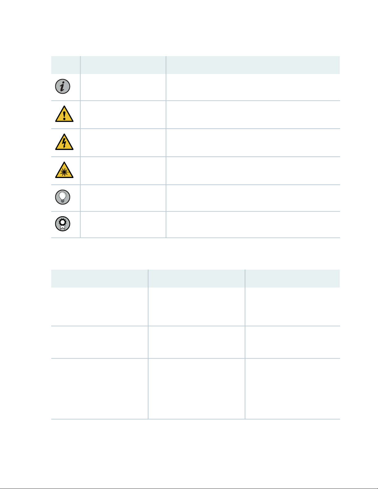
Table 1: Notice Icons
x
DescriptionMeaningIcon
Indicates important features or instructions.Informational note
Caution
Indicates a situation that might result in loss of data or hardware
damage.
Alerts you to the risk of personal injury or death.Warning
Alerts you to the risk of personal injury from a laser.Laser warning
Indicates helpful information.Tip
Alerts you to a recommended use or implementation.Best practice
Table 2 on page x defines the text and syntax conventions used in this guide.
Table 2: Text and Syntax Conventions
ExamplesDescriptionConvention
Fixed-width text like this
Italic text like this
Represents text that you type.Bold text like this
Represents output that appears on
the terminal screen.
Introduces or emphasizes important
•
new terms.
Identifies guide names.
•
Identifies RFC and Internet draft
•
titles.
To enter configuration mode, type
the configure command:
user@host> configure
user@host> show chassis alarms
No alarms currently active
A policy term is a named structure
•
that defines match conditions and
actions.
Junos OS CLI User Guide
•
RFC 1997, BGP Communities
•
Attribute
Page 11

Table 2: Text and Syntax Conventions (continued)
xi
ExamplesDescriptionConvention
Italic text like this
Text like this
< > (angle brackets)
| (pipe symbol)
Represents variables (options for
which you substitute a value) in
commands or configuration
statements.
Represents names of configuration
statements, commands, files, and
directories; configuration hierarchy
levels; or labels on routing platform
components.
variables.
Indicates a choice between the
mutually exclusive keywords or
variables on either side of the symbol.
The set of choices is often enclosed
in parentheses for clarity.
Configure the machine’s domain
name:
[edit]
root@# set system domain-name
domain-name
To configure a stub area, include
•
the stub statement at the [edit
protocols ospf area area-id]
hierarchy level.
The console port is labeled
•
CONSOLE.
stub <default-metric metric>;Encloses optional keywords or
broadcast | multicast
(string1 | string2 | string3)
# (pound sign)
[ ] (square brackets)
Indention and braces ( { } )
; (semicolon)
GUI Conventions
Indicates a comment specified on the
same line as the configuration
statement to which it applies.
Encloses a variable for which you can
substitute one or more values.
Identifies a level in the configuration
hierarchy.
Identifies a leaf statement at a
configuration hierarchy level.
rsvp { # Required for dynamic MPLS
only
community name members [
community-ids ]
[edit]
routing-options {
static {
route default {
nexthop address;
retain;
}
}
}
Page 12
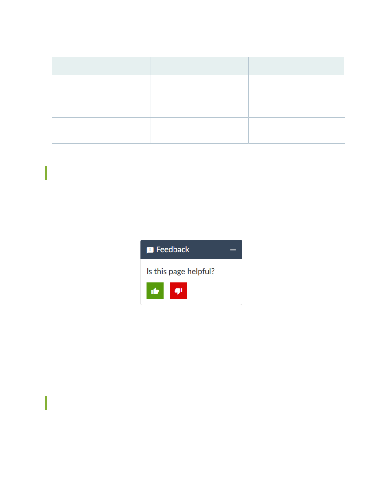
Table 2: Text and Syntax Conventions (continued)
xii
ExamplesDescriptionConvention
Bold text like this
> (bold right angle bracket)
Represents graphical user interface
(GUI) items you click or select.
Separates levels in a hierarchy of
menu selections.
In the Logical Interfaces box, select
•
All Interfaces.
To cancel the configuration, click
•
Cancel.
In the configuration editor hierarchy,
select Protocols>Ospf.
Documentation Feedback
We encourage you to provide feedback so that we can improve our documentation. You can use either
of the following methods:
Online feedback system—Click TechLibrary Feedback, on the lower right of any page on the Juniper
•
Networks TechLibrary site, and do one of the following:
Click the thumbs-up icon if the information on the page was helpful to you.
•
Click the thumbs-down icon if the information on the page was not helpful to you or if you have
•
suggestions for improvement, and use the pop-up form to provide feedback.
E-mail—Send your comments to techpubs-comments@juniper.net. Include the document or topic name,
•
URL or page number, and software version (if applicable).
Requesting Technical Support
Technical product support is available through the Juniper Networks Technical Assistance Center (JTAC).
If you are a customer with an active Juniper Care or Partner Support Services support contract, or are
Page 13

covered under warranty, and need post-sales technical support, you can access our tools and resources
online or open a case with JTAC.
JTAC policies—For a complete understanding of our JTAC procedures and policies, review the JTAC User
•
Guide located at https://www.juniper.net/us/en/local/pdf/resource-guides/7100059-en.pdf.
Product warranties—For product warranty information, visit https://www.juniper.net/support/warranty/.
•
JTAC hours of operation—The JTAC centers have resources available 24 hours a day, 7 days a week,
•
365 days a year.
Self-Help Online Tools and Resources
For quick and easy problem resolution, Juniper Networks has designed an online self-service portal called
the Customer Support Center (CSC) that provides you with the following features:
Find CSC offerings: https://www.juniper.net/customers/support/
•
Search for known bugs: https://prsearch.juniper.net/
•
xiii
Find product documentation: https://www.juniper.net/documentation/
•
Find solutions and answer questions using our Knowledge Base: https://kb.juniper.net/
•
Download the latest versions of software and review release notes:
•
https://www.juniper.net/customers/csc/software/
Search technical bulletins for relevant hardware and software notifications:
•
https://kb.juniper.net/InfoCenter/
Join and participate in the Juniper Networks Community Forum:
•
https://www.juniper.net/company/communities/
Create a service request online: https://myjuniper.juniper.net
•
To verify service entitlement by product serial number, use our Serial Number Entitlement (SNE) Tool:
https://entitlementsearch.juniper.net/entitlementsearch/
Creating a Service Request with JTAC
You can create a service request with JTAC on the Web or by telephone.
Visit https://myjuniper.juniper.net.
•
Call 1-888-314-JTAC (1-888-314-5822 toll-free in the USA, Canada, and Mexico).
•
For international or direct-dial options in countries without toll-free numbers, see
https://support.juniper.net/support/requesting-support/.
Page 14

1
CHAPTER
Installation and Configuration Overview
Platform and Software Compatibility | 15
NorthStar Controller System Requirements | 18
Changing Control Packet Classification Using the Mangle Table | 28
Page 15

Platform and Software Compatibility
The NorthStar Controller 6.1.0 release is qualified to work with Junos OS Release 18.3R2.4. We recommend
contacting JTAC for information about the compatibility of other Junos OS releases.Table 3 on page 15
lists feature-specific Junos OS requirements. The NorthStar features listed have been qualified with the
specified Junos OS release and are intended to work with that release.
Table 3: Feature-Specific Junos OS Requirements
Junos OS ReleaseNorthStar Feature
15.1F6Analytics
17.2R1Segment Routing (SPRING), MD5 authentication for PCEP, P2MP, Admin
groups
18.3R2PCEP-Provisioned P2MP Groups
15
19.4R1PCEP-Provisioned P2MP Groups with MVPN (S,G) Service Mapping via
Flowspec
19.2R1.8EPE
19.2R1.2Bandwidth sizing and container LSPs for SR-TE LSPs
19.4R3, 20.1R1PCC Delegated LSP Support for SR LSPs
NOTE: The Path Computation Element Protocol (PCEP) configuration on the PCC routers does
not persist across upgrades when the SDN package is not part of the installation binary. Before
upgrading the Junos OS image to this release, save the existing configuration to a file by using
the save command. After you upgrade the Junos OS image on each PCC router, use the load
override command to restore the PCEP configuration.
The NorthStar Controller is supported on the following Juniper platforms: M Series, T Series, MX Series,
PTX Series, and QFX10008. As of Junos OS Release 17.4R1, NorthStar Controller is also supported on
QFX5110, QFX5100, and QFX5200. Please contact JTAC for more information.
Junos OS supports Internet draft draft-crabbe-pce-pce-initiated-lsp-03 for the stateful PCE-initiated LSP
implementation (M Series, MX Series, PTX Series, T Series, and QFX Series).
Page 16
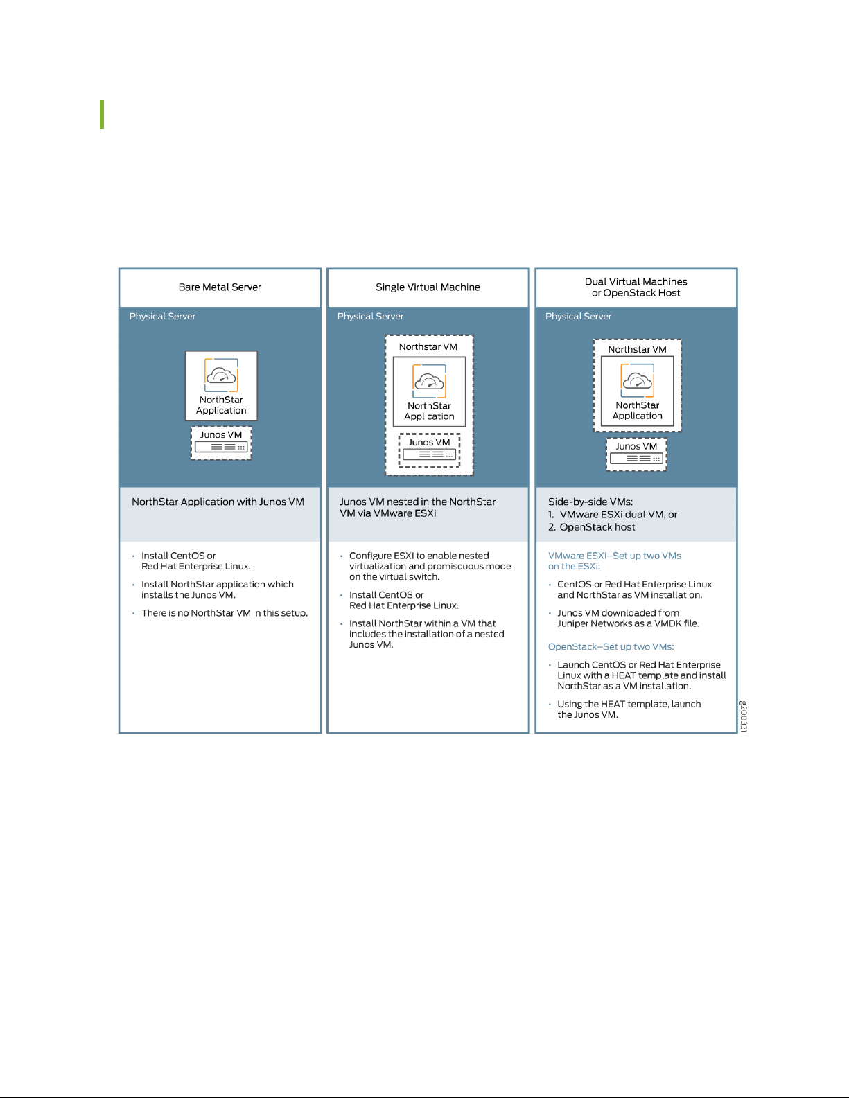
Installation Options
There are three NorthStar Controller installation options for use with Junos VM as summarized in
Figure 1 on page 16.
Figure 1: NorthStar/Junos VM Installation Options
16
You can also install NorthStar Controller using cRPD as summarized in Figure 2 on page 17.
Page 17
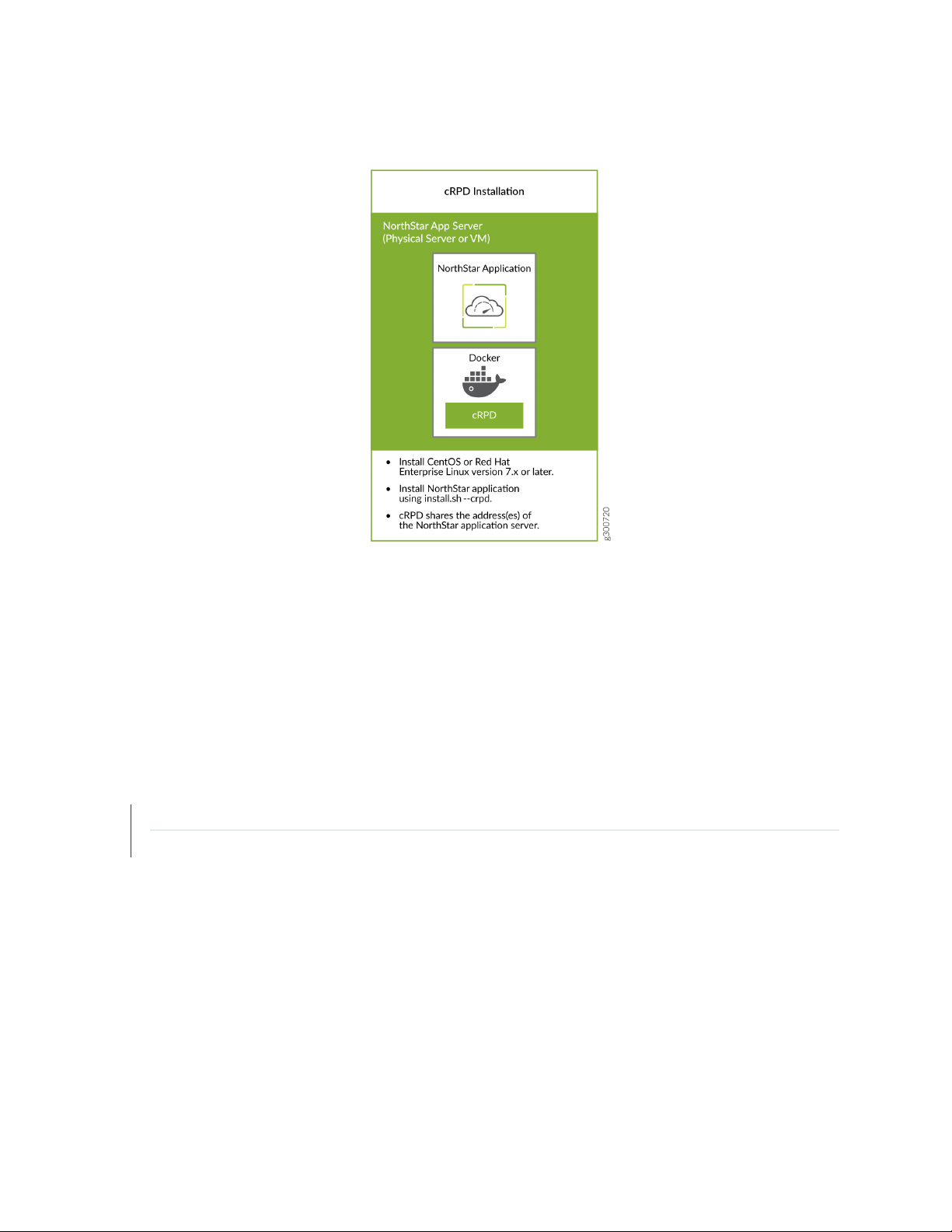
Figure 2: NorthStar/cRPD Installation
17
For installation procedures, see:
Installing the NorthStar Controller on page 38
•
This topic also includes information about installing with NorthStar cRPD.
Overview of NorthStar Controller Installation in an OpenStack Environment on page 78
•
RELATED DOCUMENTATION
NorthStar Controller System Requirements | 18
Installing the NorthStar Controller | 38
Page 18

NorthStar Controller System Requirements
The NorthStart Controller runs on Linux systems running CentOS 7 or Red Hat Enterprise Linux (RHEL)
7.
Ensure that:
You use a supported version of CentOS Linux or Red Hat Enterprise Linux (RHEL). These are our Linux
•
recommendations:
CentOS Linux or RHEL 7.6 or 7.7 image. Earlier versions are not supported.
•
Install your choice of supported Linux version using the minimal ISO.
•
You use RAM, number of virtual CPUs, and hard disk specified in “Server Sizing Guidance” on page 18
•
for your installation.
You open the ports listed in “Firewall Port Guidance” on page 23.
•
18
NOTE: When upgrading NorthStar Controller, files are backed up to the /opt directory.
Server Sizing Guidance
The guidance in this section should help you to configure your servers with sufficient resources to efficiently
and effectively support the NorthStar Controller functions. The recommendations in this section are the
result of internal testing combined with field data.
A typical NorthStar deployment contains the following systems:
An application system
•
The application system contains the path computation element (PCE), the path computation server (PCS),
the components for Web access, topology acquisition, CLI or SNMP message collection and, a
configuration database.
An analytics system
•
The analytics system is used for telemetry and collecting NetFlow data, and contains the analytics
database. The analytics system is used in deployments tracking traffic levels of a network.
(Optional) A dedicated or secondary collector
•
Page 19

A secondary collector is used for collecting CLI and SNMP messages from large nodes and is needed
when there is a need for a heavy collection of data; see Table 5 on page 20.
(Optional) A dedicated planner node
•
A planner node is required for running offline network simulation on a system other than the application
system; see Table 5 on page 20.
For high availability deployments, described in “Configuring a NorthStar Cluster for High Availability” on
page 143, a cluster would have 3 or more application and analytics systems, but they would be sized similarly
to a deployment with a single application system and a single analytics system.
Table 4 on page 19 outlines the estimated server requirements of the application and analytics systems
by network size.
Table 4: Server Requirements for Application and Analytics Systems by Network Size
Medium (<75
nodes)
(RAM / vCPU /
HDD)
Large (<300 nodes)
(RAM / vCPU / HDD)
XL (300+ nodes)*
(RAM / vCPU / HDD)
Instance
Type
POC/LAB
(RAM / vCPU /
HDD)
19
Application
500G
For collecting a large number of SNMP and CLI messages
on a single, non-high availability (HA) system, you may
require additional 16GB RAM and 8 vCPUs or a secondary
collector; see Table 5 on page 20.
Analytics
500G
NetFlow deployments may require additional 16G to 32G RAM and doubling of
the virtual CPUs on the analytics system.
NOTE: Based on the number of devices in your network, check with your Juniper Networks representative to confirm
your specific requirements for networks in the XL category.
128G / 8vCPU / 2T96G / 8vCPU / 1.5T64G / 8vCPU / 1T16G / 4vCPU /
64G / 12vCPU / 3T64G / 8vCPU/ 2T48G / 6vCPU/ 1T16G/ 4vCPU/
Table 5 on page 20 outlines the estimated server requirements for the secondary collectors and dedicated
planner.
Page 20

Table 5: Server Requirements for Secondary Collector and Dedicated Planner
20
POC/LAB
(RAM / vCPU /
HDD)Instance Type
Collectors
Planner
NOTE: All-In-One is a configuration, where all the components are installed in a single virtual machine, is intended
only for demonstration purposes. It is not recommended for production deployments or lab configurations intended
to model production deployments.
Medium (<75 nodes)
(RAM / vCPU /
HDD)
Additional RAM may be necessary based on the number of active planner
sessions and complexity of models.
Large (<300 nodes)
(RAM / vCPU /
HDD)
XL (300+ nodes)
(RAM / vCPU /
HDD)
Not applicableNot applicableNot applicable24G / 8vCPU/ 1TAll-In-One
16G / 8vCPU / 500G16G / 8vCPU / 500G16G / 8vCPU / 500G8G / 4vCPU / 200GSecondary
16G / 8vCPU / 1T16G / 8vCPU / 1T16G / 8vCPU / 1T8G / 4vCPU / 200GDedicated
When installing the minimal installation Centos or RHEL Linux, the filesystems can be collapsed to a single
root (/) filesystem or separate filesystems. If you are using separate filesystems, you can assign space for
each customer according to the size mentioned in Table 6 on page 20 for the different directories.
Table 6: Recommended Space for Filesystem
24G/tmp
/opt
filesystem
PurposeSpace RequirementFilesystem
Linux kernel and necessary files for boot1G/boot
Not needed, but can have minimal configuration0 to 4Gswap
Operating system (including /usr)10G/
Containerized processes (application system only)20G/var/lib/docker
NorthStar debug files in case of process error (application
system only)
NorthStar componentsRemaining space in the
Page 21

Additional Disk Space for JTI Analytics in ElasticSearch
Considerable storage space is needed to support JTI analytics in ElasticSearch. Each JTI record event
requires approximately 330 bytes of disk space. A reasonable estimate of the number of events generated
is (<num-of-interfaces> + <number-of-LSPs>) ÷ reporting-interval-in-seconds = events per second.
So for a network with 500 routers, 50K interfaces, and 60K LSPs, with a configured five-minute reporting
interval (300 seconds), you can expect something in the neighborhood of 366 events per second to be
generated. At 330 bytes per event, it comes out to 366 events x 330 bytes x 86,400 seconds in a day =
over 10G of disk space per day or 3.65T per year. For the same size network, but with a one-minute
reporting interval (60 seconds), you would have a much larger disk space requirement—over 50G per day
or 18T per year.
There is an additional roll-up event created per hour per element for data aggregation. In a network with
50K interfaces and 60K LSPs (total of 110K elements), you would have 110K roll-up events per hour. In
terms of disk space, that would be 110K events per hour x 330 bytes per event x 24 hours per day = almost
1G of disk space required per day.
21
For a typical network of about 100K elements (interfaces + LSPs), we recommend that you allow for an
additional 11G of disk space per day if you have a five-minute reporting interval, or 51G per day if you
have a one-minute reporting interval.
See NorthStar Analytics Raw and Aggregated Data Retention in the NorthStar Controller User Guide for
information about customizing data aggregation and retention parameters to reduce the amount of disk
space required by ElasticSearch.
Additional Disk Space for Network Events in Cassandra
The Cassandra database is another component that requires additional disk space for storage of network
events.
Using that same example of 50K interfaces and 60K LSPs (110 elements) and estimating one event every
15 minutes (900 seconds) per element, there would be 122 events per second. The storage needed would
then be 122 events per second x 300 bytes per event x 86,400 seconds per day = about 3.2 G per day, or
1.2T per year.
Using one event every 5 minutes per element as an estimate instead of every 15 minutes, the additional
storage requirement is more like 9.6G per day or 3.6T per year.
For a typical network of about 100K elements (interfaces + LSPs), we recommend that you allow for an
additional 3-10G of disk space per day, depending on the rate of event generation in your network.
By default, NorthStar keeps event history for 35 days. To customize the number of days event data is
retained:
1. Modify the dbCapacity parameter in /opt/northstar/data/web_config.json
Page 22

2. Restart the pruneDB process using the supervisorctl restart infra:prunedb command.
Collector (Celery) Memory Requirements
When you use the collector.sh script to install secondary collectors on a server separate from the NorthStar
application (for distributed collection), the script installs the default number of collector workers described
in Table 7 on page 22. The number of celery processes started by each worker is the number of cores in
the CPU plus one. So in a 32-core server (for example), the one installed default worker would start 33
celery processes. Each celery process uses about 50M of RAM.
Table 7: Default Workers, Processes, and Memory by Number of CPU Cores
Minimum RAM RequiredTotal Worker ProcessesWorkers InstalledCPU Cores
22
41-4
(CPUs +1) x 4 = 20
35-8
(CPUs +1) x 2 = 18
116
(CPUs +1) x 1 = 17
132
(CPUs +1) x 1 = 33
1 GB20
1 GB18
1 GB17
2 GB33
See “Secondary Collector Installation for Distributed Data Collection” on page 140 for more information
about distributed data collection and secondary workers.
The default number of workers installed is intended to optimize server resources, but you can change the
number by using the provided config_celery_workers.sh script. See “Collector Worker Installation
Customization” on page 138 for more information. You can use this script to balance the number of workers
installed with the amount of memory available on the server.
NOTE: This script is also available to change the number of workers installed on the NorthStar
application server from the default, which also follows the formulas shown in Table 7 on page 22.
Page 23

Firewall Port Guidance
The ports listed in Table 8 on page 23 must be allowed by any external firewall being used. The ports with
the word cluster in their purpose descriptions are associated with high availability (HA) functionality. If
you are not planning to configure an HA environment, you can ignore those ports. The ports with the word
Analytics in their purpose descriptions are associated with the Analytics feature. If you are not planning
to use Analytics, you can ignore those ports. The remaining ports listed must be kept open in all
configurations.
Table 8: Ports That Must Be Allowed by External Firewalls
PurposePort
23
179
830
BGP: JunosVM or cRPD for router BGP-LS—not needed if IGP is used for topology acquisition. In
a cRPD installation, the router connects port 179/TCP (BGP) directly to the NorthStar application
server. cRPD runs as a process inside the NorthStar application server. Junos VM and cRPD are
mutually exclusive.
SNMP161
NTAD450
NETCONF communication between NorthStar Controller and routers. This is the default port for
NETCONFD, but in some installations, port 22 is preferred. To change to port 22, access the
NorthStar CLI as described in “Configuring NorthStar Settings Using the NorthStar CLI” on page 66,
and modify the value of the port setting. Use the set northstar netconfd device-connection-pool
netconf port command.
Syslog: Default Junos Telemetry Interface reports for RPM probe statistics (supports Analytics)1514
RADIUS authentication1812
Containerized Management Daemon (cMGD). Used to access NorthStar CLI.2222
3000
Zookeeper cluster2888
JTI: Default Junos Telemetry Interface reports for IFD, IFL, and LSP (supports NorthStar Analytics).
In previous NorthStar releases, three JTI ports were required (2000, 2001, 2002). Starting with
Release 4.3.0, this single port is used instead.
Model Driven Telemetry (MDT)3001
MDT3002
Zookeeper cluster3888
Page 24

Table 8: Ports That Must Be Allowed by External Firewalls (continued)
PurposePort
PCEP: PCC (router) to NorthStar PCE server4189
cMGD-REST5000
RabbitMQ5672
Redis6379
Communications port to NorthStar Planner7000
Cassandra database cluster7001
Health Monitor8124
24
Web: Web client/REST to secure web server (https)8443
Netflow9000
Remote Planner Server9042
Elasticsearch9201
Elasticsearch cluster9300
10001
BMP passive mode: By default, the monitor listens on this port for incoming connections from the
network.
Cassandra database cluster17000
PRPD: NorthStar application to router network50051
Figure 3 on page 25 details the direction of data flow through the ports, when node clusters are not being
used. Figure 4 on page 26 and Figure 5 on page 26 detail the additional flows for NorthStar application
HA clusters and analytics HA clusters, respectively.
Page 25
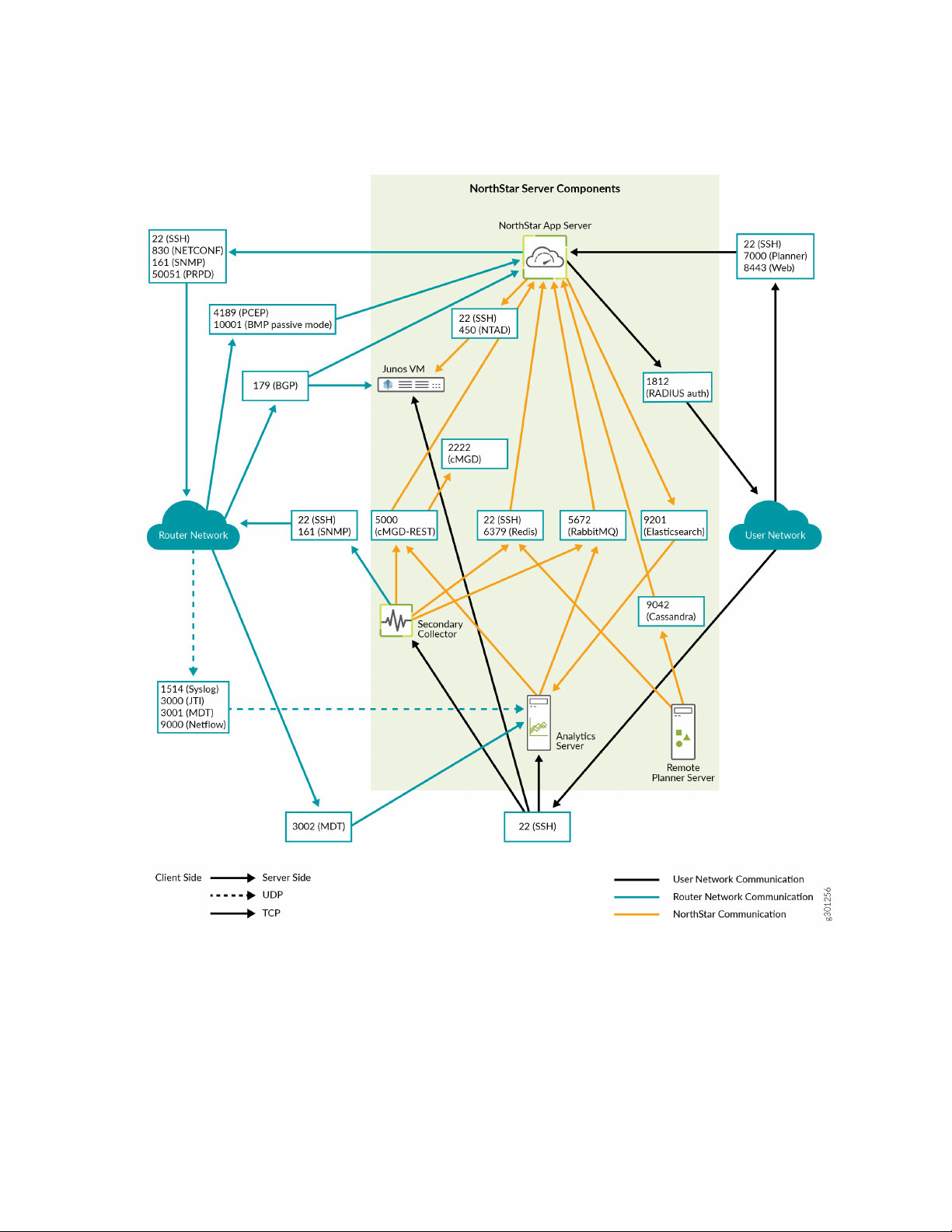
Figure 3: NorthStar Main Port Map
25
Page 26
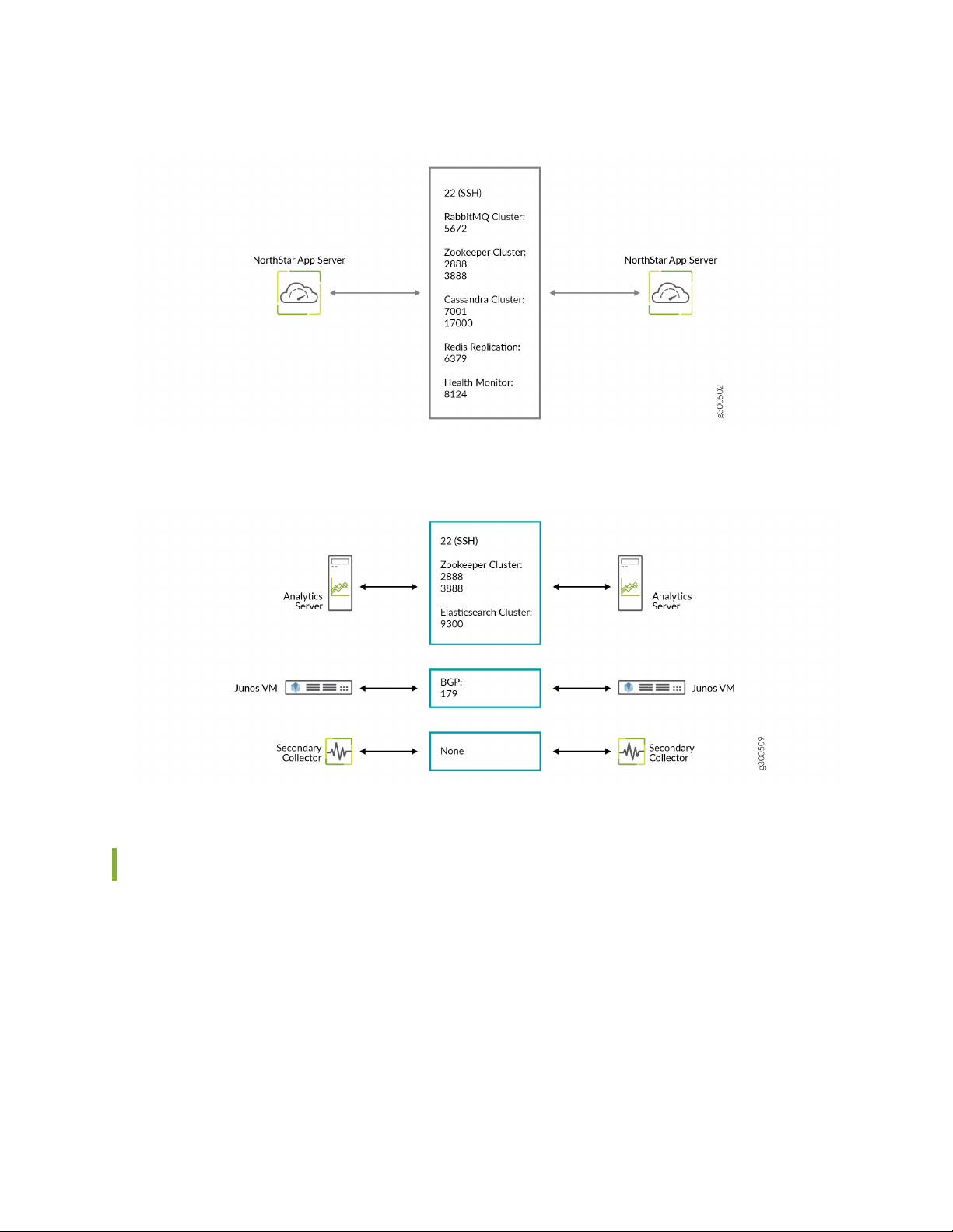
Figure 4: NorthStar Application HA Port Map
Figure 5: Analytics HA Port Map
26
Analytics Requirements
In addition to ensuring that ports 3000 and 1514 are kept open, using the NorthStar analytics features
requires that you counter the effects of Reverse Path Filtering (RPF) if necessary. If your kernel does RPF
by default, you must do one of the following to counter the effects:
Disable RPF.
•
Ensure there is a route to the source IP address of the probes pointing to the interface where those
•
probes are received.
Page 27

Specify loose mode reverse filtering (if the source address is routable with any of the routes on any of
•
the interfaces).
Two-VM Installation Requirements
A two-VM installation is one in which the JunosVM is not bundled with the NorthStar Controller software.
VM Image Requirements
The NorthStar Controller application VM is installed on top of a Linux VM, so Linux VM is required. You
•
can obtain a Linux VM image in either of the following ways:
Use the generic version provided by most Linux distributors. Typically, these are cloud-based images
•
for use in a cloud-init-enabled environment, and do not require a password. These images are fully
compatible with OpenStack.
27
Create your own VM image. Some hypervisors, such as generic DVM, allow you to create your own
•
VM image. We recommend this approach if you are not using OpenStack and your hypervisor does
not natively support cloud-init.
The JunosVM is provided in Qcow2 format when inside the NorthStar Controller bundle. If you download
•
the JunosVM separately (not bundled with NorthStar) from the NorthStar download site, it is provided
in VMDK format.
The JunosVM image is only compatible with IDE disk controllers. You must configure the hypervisor to
•
use IDE rather than SATA controller type for the JunosVM disk image.
glance image-update --property
hw_disk_bus=ide --property
hw_cdrom_bus=ide
JunosVM Version Requirements
If you have, and want to continue using a version of JunosVM older than Release 17.2R1, you can change
the NorthStar configuration to support it, but segment routing support would not be available. See “Installing
the NorthStar Controller” on page 38 for the configuration steps.
VM Networking Requirements
The following networking requirements must be met for the two-VM installation approach to be successful:
Each VM requires the following virtual NICs:
•
Page 28

One connected to the external network
•
One for the internal connection between the NorthStar application and the JunosVM
•
One connected to the management network if a different interface is required between the router
•
facing and client facing interfaces
We recommend a flat or routed network without any NAT for full compatibility.
•
A virtual network with one-to-one NAT (usually referenced as a floating IP) can be used as long as BGP-LS
•
is used as the topology acquisition mechanism. If IS-IS or OSPF adjacency is required, it should be
established over a GRE tunnel.
NOTE: A virtual network with n-to-one NAT is not supported.
28
Changing Control Packet Classification Using the Mangle Table
The NorthStar application uses default classification for control packets. To support a different packet
classification, you can use Linux firewall iptables to reclassify packets to a different priority.
The following sample configuration snippets show how to modify the ToS bits using the mangle table,
changing DSCP values to cs6.
Zookeeper:
iptables -t mangle -A POSTROUTING -p tcp -sport 3888 -j DSCP -set-dscp-class cs6
iptables -t mangle -A POSTROUTING -p tcp -dport 3888 -j DSCP -set-dscp-class cs6
iptables -t mangle -A POSTROUTING -p tcp -sport 2888 -j DSCP -set-dscp-class cs6
iptables -t mangle -A POSTROUTING -p tcp -dport 2888 -j DSCP -set-dscp-class cs6
Cassandra database:
iptables -t mangle -A POSTROUTING -p tcp -sport 7001 -j DSCP -set-dscp-class cs6
iptables -t mangle -A POSTROUTING -p tcp -dport 7001 -j DSCP -set-dscp-class cs6
iptables -t mangle -A POSTROUTING -p tcp -sport 17000 -j DSCP -set-dscp-class cs6
iptables -t mangle -A POSTROUTING -p tcp -dport 17000 -j DSCP -set-dscp-class cs6
Page 29

iptables -t mangle -A POSTROUTING -p tcp -sport 7199 -j DSCP -set-dscp-class cs6
iptables -t mangle -A POSTROUTING -p tcp -dport 7199 -j DSCP -set-dscp-class cs6
RabbitMQ:
iptables -t mangle -A POSTROUTING -p tcp -sport 25672 -j DSCP -set-dscp-class cs6
iptables -t mangle -A POSTROUTING -p tcp -dport 25672 -j DSCP -set-dscp-class cs6
iptables -t mangle -A POSTROUTING -p tcp -sport 15672 -j DSCP -set-dscp-class cs6
iptables -t mangle -A POSTROUTING -p tcp -dport 15672 -j DSCP -set-dscp-class cs6
iptables -t mangle -A POSTROUTING -p tcp -sport 4369 -j DSCP -set-dscp-class cs6
iptables -t mangle -A POSTROUTING -p tcp -dport 4369 -j DSCP -set-dscp-class cs6
NTAD:
iptables -t mangle -A POSTROUTING -p tcp -dport 450 -j DSCP -set-dscp-class cs6
29
PCEP protocol:
iptables -t mangle -A POSTROUTING -p tcp -sport 4189 -j DSCP -set-dscp-class cs6
ICMP packets used by ha_agent (replace the variable NET-SUBNET with your configured network subnet):
iptables -t mangle -A POSTROUTING -p icmp -s NET-SUBNET –d NET-SUBNET -j DSCP
-set-dscp-class cs6
To verify that the class of service setting matches best effort, use the following command on the NorthStar
server:
tcpdump -i interface-name -v -n -s 1500 “(src host host-IP ) && (ip[1]==0)”
To verify that the class of service setting matches cs6, use the following command on the NorthStar server:
tcpdump -i interface-name -v -n -s 1500 “(src host host-IP ) && (ip[1]==192)”
Page 30

2
CHAPTER
Installation on a Physical Server
Using an Ansible Playbook to Automate NorthStar Installation | 31
Installing the NorthStar Controller | 38
Configuring NorthStar Settings Using the NorthStar CLI | 66
Uninstalling the NorthStar Controller Application | 75
Page 31

Using an Ansible Playbook to Automate NorthStar Installation
IN THIS SECTION
Before You Begin | 32
Creating the Ansible Inventory File | 33
Executing the Playbook | 34
Installing Data Collectors and Secondary Collectors for Analytics | 35
Variables | 36
31
An Ansible playbook is available for download from the NorthStar download page. The playbook enables
automation of NorthStar software installation, and is appropriate for both lab and production systems. If
you are not familiar with the Ansible open-source automation tool, information is readily available online.
Sample resources include:
For the Ansible User Guide:
•
https://docs.ansible.com/ansible/latest/user_guide/index.html
For an introduction to the inventory file format:
•
https://docs.ansible.com/ansible/latest/user_guide/intro_inventory.html
For information about “become” (privilege escalation):
•
https://docs.ansible.com/ansible/latest/user_guide/become.html
For information on encrypting secret variables:
•
https://docs.ansible.com/ansible/latest/user_guide/vault.html
For a complete list of arguments that can be included when executing the playbook:
•
https://docs.ansible.com/ansible/latest/cli/ansible-playbook.html
The Ansible playbook installs NorthStar with cRPD. There is no playbook available for a Junos VM
installation.
See “Installing the NorthStar Controller” on page 38 for installation procedures not using the Ansible
playbook.
Page 32

The Ansible playbook requires a host machine (VM or a laptop/desktop) from which the installation is
initiated. This host is called the “control node”. The status of the installation is maintained on the control
node to facilitate future configuration changes. This is also a good place to save the inventory file (hosts.yml)
and license files for a future reinstallation or update. You will install the public SSH keys existing in the
control node on the hosts targeted for installation (the “managed nodes”) so Ansible can communicate
with those nodes.
Before You Begin
To prepare for executing the Ansible playbook:
1. Install the following on your control node:
Linux operating system
•
Python
•
32
Python-pip (for installing Ansible)
•
SSH
•
Ansible
•
We recommend using virtualenv to create an isolated Python environment in which to install Ansible.
It creates a folder with all the necessary executables. You can install Ansible using the pip command
within the virtualenv. You could also use pip to install Ansible in the system environment.
Here is an example of Ansible installation using virtualenv:
$ virtualenv ansible
$ source ansible/bin/activate
$ pip install ansible
2. Identify all the managed nodes where NorthStar software is to be installed. Ensure that each node has
the following:
Basic operating system (Red Hat Enterprise Linux 7.x or CentOS 7.x)
•
Network connectivity
•
SSH server
•
3. Ensure that you can SSH from the control node to all of the managed nodes.
To execute the playbook, you must be able to connect to each managed node and become root. You
can set this up by adding your SSH key to the ~/.ssh/authorized_keys file on each managed node either
for root directly, or for another account that can become root by executing sudo without a password.
Page 33

An alternate method is to use variables to specify the username/password to connect to the managed
nodes and the sudo password in the inventory file. These are the variables:
ansible_user
•
The user to connect to, such as root. The default is the current user.
ansible_password
•
Password that authenticates the ansible_user.
ansible_become
•
Set this to true if ansible_user is not root.
ansible_sudo_password
•
Password provided to sudo.
4. Copy the Ansible playbook for NorthStar and the NorthStar-Bundle.rpm to the control node and change
to that directory.
33
Creating the Ansible Inventory File
Create a custom inventory file for your NorthStar installation. The inventory is a group of lists that define
the managed nodes in your planned NorthStar installation. The Ansible playbook for NorthStar contains
a sample inventory file named hosts.yml.sample that you can use as a template to start a custom inventory
file. The default name for the inventory file is hosts.yml. Use a text editor to customize the inventory file.
The template inventory file is organized into several groups:
all
•
Contains the subsection vars to define variables that apply to all managed nodes. For example, ansible_user
defines the account name used to connect to the managed nodes.
northstar
•
Defines nodes and variables for managed nodes that will run NorthStar services such as PCS, TopoServer,
and web front end. Nodes in the northstar group should define a northstar_license variable that contains
the license information for that node
northstar_ha
•
Contains nodes or subgroups of nodes that are configured for NorthStar high availability.
northstar_analytics
•
Contains nodes and variables for analytics.
northstar_collector
•
Page 34

Contains nodes and variables for analytics secondary collectors.
This example shows a portion of an inventory file including some of these groups:
all:
vars: # define common variables
ansible_user: root # connect directly to root@target
northstar_ha_vip: 1.2.3.1 # define HA virtual ip address
northstar_password: PASSSWORD # PASSWORD can be encrypted
northstar_crpd_asn: "100" # configure CRPD
northstar:
hosts:
1.2.3.4: # target-host by ip-address or hostname
northstar_license_file: npatpw.host1 # file containing license
1.2.3.5:
northstar_license: | # (alt:) inline license information:
expire_date=... # each line is indented by 2 space
card=...
MAC=ab:cd:ef:00:01:02
usercount=...
. . .
1.2.3.6:
. . .
northstar_ha:
children: # define subgroup (optional)
site1:
vars:
northstar_ha_site: site1 # common variable for hosts in this child
hosts:
1.2.3.4: # re-use host defined in northstar group
northstar_ha_priority: 10 # override priority
1.2.3.5: # these two hosts use default values
1.2.3.6: #
34
You can encrypt secret variables, such as northstar_password or ansible_password, using the ansible-vault
encrypt_string command. More information is available here:
https://docs.ansible.com/ansible/latest/user_guide/vault.html.
Executing the Playbook
After defining the inventory file, execute the ansible -m ping all command to verify that all managed nodes
are defined correctly, are reachable, and that SSH login was successful.
Page 35

Execute the ./install.yml (or ansible-playbook install.yml) command to execute the installation playbook
and install all managed nodes as defined in the inventory file. You can add optional arguments to the
install.yml command. Some useful examples include:
-e key=value
•
Extra variables. For example, -e northstar_bundle_rpm=NorthStar-Bundle-6.1.0.xxx.rpm
-i inventory-file
•
Use a different inventory file. You might utilize this, for example, if you use the control node to install
software for independent clusters.
-l limit
•
Limit execution to a subset of managed nodes. For example, -l 1.2.3.4,1.2.3.5 would only install on those
two managed nodes.
-t taglist
•
Limit execution to a set of tagged tasks. For example, -t northstar would only install the NorthStar
application.
35
--ask-vault-pass
•
Ask for the decryption key for embedded secrets.
Installing Data Collectors and Secondary Collectors for Analytics
You can install NorthStar data collectors to support either of two analytics configurations:
Analytics co-hosted with the NorthStar application
•
For this configuration, add the same managed nodes to the northstar_analytics inventory group that
are in the northstar inventory group.
External analytics node or cluster
•
For this configuration, add one or more managed nodes to the northstar_analytics inventory group.
Install analytics secondary collectors by adding managed nodes to the northstar_collector inventory group.
In order to successfully install secondary collectors, the installation script needs access to a node running
the NorthStar application. The primary node must either be installed together with analytics/collector
nodes, or it must be running before the analytics/collector nodes are installed. The script takes the required
information from the northstar inventory group, but you can override that by using the variable
northstar_primary.
Page 36

Variables
The variables provided specifically for use with the NorthStar playbook are listed in Table 9 on page 36.
Table 9: NorthStar Ansible Playbook Variables
DescriptionVariable Name
Name of bundle RPM to install.northstar_bundle_rpm
36
chrony_config_server
northstar_crpd_asn
List of NTP servers.
If you do not specify any NTP servers, the managed nodes are configured
to synchronize with the following four NTP servers:
0.pool.ntp.org
•
1.pool.ntp.org
•
2.pool.ntp.org
•
3.pool.ntp.org
•
Per-node NorthStar license file.northstar_license_file
Per-node NorthStar license (inline).northstar_license
ASN for cRPD route reflector.
The default behavior is that the default ASN in the NorthStar configuration
script is not modified. The default ASN in the NorthStar configuration
script is 64512.
cRPD license file.northstar_crpd_license_file
northstar_ha_group
northstar_ha_site
northstar_ha_priority
cRPD license (inline).northstar_crpd_license
Managed nodes that are part of HA.
By default, all members of the northstar_ha inventory group are included.
Virtual IP address for HA.northstar_ha_vip
Name of a geo-HA site.
The default is site1.
Per-node HA priority.
The default is 100.
Page 37

Table 9: NorthStar Ansible Playbook Variables (continued)
DescriptionVariable Name
37
northstar_primary
northstar_app_nodes
northstar_analytics_priority
Table2 lists some other useful variables.
The NorthStar application node used to configure remote analytics and
collector nodes. The primary node must either be installed together with
analytics/collector nodes, or it must be running before the
analytics/collector nodes are installed.
The default is the first member of the northstar inventory group .
Managed nodes running the NorthStar application.
By default, all members of the northstar inventory group are included.
Per-node HA priority.
The default is 100.
Virtual IP address for the analytics cluster.northstar_analytics_vip
DescriptionVariable
User to connect to the managed node.ansible_user
RELATED DOCUMENTATION
Installing the NorthStar Controller | 38
Password to connect to the control node.ansible_password
Set this to true if ansible_user is not root.ansible_become
Password provided to sudo.ansible_sudo_password
Page 38

Installing the NorthStar Controller
IN THIS SECTION
Activate Your NorthStar Software | 40
Download the Software | 40
If Upgrading, Back Up Your JunosVM Configuration and iptables | 41
Install NorthStar Controller | 41
Configure Support for Different JunosVM Versions | 43
Create Passwords | 45
Enable the NorthStar License | 45
Adjust Firewall Policies | 46
Launch the Net Setup Utility | 46
38
Configure the Host Server | 48
Configure the JunosVM and its Interfaces | 53
Configure Junos cRPD Settings | 58
Set Up the SSH Key for External JunosVM | 60
Upgrade the NorthStar Controller Software in an HA Environment | 63
You can use the procedures described in the following sections if you are performing a fresh install of
NorthStar Controller or upgrading from an earlier release, unless you are using NorthStar analytics and are
upgrading from a release older than NorthStar 4.3. Steps that are not required if upgrading are noted. Before
performing a fresh install of NorthStar, you must first use the ./uninstall_all.sh script to uninstall any older
versions of NorthStar on the device. See “Uninstalling the NorthStar Controller Application” on page 75.
If you are upgrading from a release earlier than NorthStar 4.3 and you are using NorthStar analytics, you
must upgrade NorthStar manually using the procedure described in “Upgrading from Pre-4.3 NorthStar
with Analytics” on page 206.
If you are upgrading NorthStar from a release earlier than NorthStar 6.0.0, you must redeploy the analytics
settings after you upgrade the NorthStar application nodes. This is done from the Analytics Data Collector
Configuration Settings menu described in “Installing Data Collectors for Analytics” on page 99. This is to
ensure that netflowd can communicate with cMGD (necessary for the NorthStar CLI available starting in
NorthStar 6.1.0).
We also recommend that you uninstall any pre-existing older versions of Docker before you install NorthStar.
Installing NorthStar will install a current version of Docker.
Page 39

The NorthStar software and data are installed in the /opt directory. Be sure to allocate sufficient disk
space. See “NorthStar Controller System Requirements” on page 18 for our memory recommendations.
NOTE: When upgrading NorthStar Controller, ensure that the /tmp directory has enough free
space to save the contents of the /opt/pcs/data directory because the /opt/pcs/data directory
contents are backed up to /tmp during the upgrade process.
If you are installing NorthStar for a high availability (HA) cluster, ensure that:
You configure each server individually using these instructions before proceeding to HA setup.
•
The database and rabbitmq passwords are the same for all servers that will be in the cluster.
•
All server time is synchronized by NTP using the following procedure:
•
1. Install NTP.
yum -y install ntp
39
2. Specify the preferred NTP server in ntp.conf.
3. Verify the configuration.
ntpq -p
NOTE: All cluster nodes must have the same time zone and system time settings. This is
important to prevent inconsistencies in the database storage of SNMP and LDP task collection
delta values.
NOTE: To upgrade NorthStar Controller in an HA cluster environment, see “Upgrade the
NorthStar Controller Software in an HA Environment” on page 63.
For HA setup after all the servers that will be in the cluster have been configured, see “Configuring a
NorthStar Cluster for High Availability” on page 143.
To set up a remote server for NorthStar Planner, see “Using a Remote Server for NorthStar Planner” on
page 164.
The high-level order of tasks is shown in Figure 6 on page 40. Installing and configuring NorthStar comes
first. If you want a NorthStar HA cluster, you would set that up next. Finally, if you want to use a remote
Page 40

server for NorthStar Planner, you would install and configure that. The text in italics indicates the topics
in the NorthStar Getting Started Guide that cover the steps.
Figure 6: High Level Process Flow for Installing NorthStar
The following sections describe the download, installation, and initial configuration of NorthStar.
NOTE: The NorthStar software includes a number of third-party packages. To avoid possible
conflict, we recommend that you only install these packages as part of the NorthStar Controller
RPM bundle installation rather than installing them manually.
40
Activate Your NorthStar Software
To obtain your serial number certificate and license key, see Obtain Your License Keys and Software for
the NorthStar Controller.
Download the Software
The NorthStar Controller software download page is available at
https://www.juniper.net/support/downloads/?p=northstar#sw.
1. From the Version drop-down list, select the version number.
2. Click the NorthStar Application (which includes the RPM bundle and the Ansible playbook) and the
NorthStar JunosVM to download them.
Page 41

If Upgrading, Back Up Your JunosVM Configuration and iptables
If you are doing an upgrade from a previous NorthStar release, and you previously installed NorthStar and
Junos VM together, back up your JunosVM configuration before installing the new software. Restoration
of the JunosVM configuration is performed automatically after the upgrade is complete as long as you use
the net_setup.py utility to save your backup.
NOTE: You must upgrade to CentOS 7.0 or a later version of CentOS before upgrading to
NorthStar 6.1.0 For information on migrating to CentOS 7.0, see Guidance for Migrating to
CentOS 7 for NorthStar 6.0.0 and Later
1. Launch the net_setup.py script:
[root@hostname~]# /opt/northstar/utils/net_setup.py
41
2. Type D and press Enter to select Maintenance and Troubleshooting.
3. Type 1 and press Enter to select Backup JunosVM Configuration.
4. Confirm the backup JunosVM configuration is stored at '/opt/northstar/data/junosvm/junosvm.conf'.
5. Save the iptables.
iptables-save > /opt/northstar/data/iptables.conf
Install NorthStar Controller
You can either install the RPM bundle on a physical server or use a two-VM installation method in an
OpenStack environment, in which the JunosVM is not bundled with the NorthStar Controller software.
The following optional parameters are available for use with the install.sh command:
––vm—Same as ./install-vm.sh, creates a two-VM installation.
––crpd—Creates a cRPD installation.
––skip-bridge—For a physical server installation, skips checking if the external0 and mgmt0 bridges exist.
Page 42

The default bridges are external0 and mgmt0. If you have two interfaces such as eth0 and eth1 in the
physical setup, you must configure the bridges to those interfaces. However, you can also define any
bridge names relevant to your deployment.
NOTE: We recommend that you configure the bridges before running install.sh.
NOTE: Bridges are not used with cRPD installations.
For a physical server installation, execute the following commands to install NorthStar Controller:
•
[root@hostname~]# yum install <rpm-filename>
[root@hostname~]# cd /opt/northstar/northstar_bundle_x.x.x/
[root@hostname~]# ./install.sh
42
NOTE: yum install works for both upgrade and fresh installation.
For a two-VM installation, execute the following commands to install NorthStar Controller:
•
[root@hostname~]# yum install <rpm-filename>
[root@hostname~]# cd /opt/northstar/northstar_bundle_x.x.x/
[root@hostname~]# ./install-vm.sh
NOTE: yum install works for both upgrade and fresh installation.
The script offers the opportunity to change the JunosVM IP address from the system default of
172.16.16.2.
Checking current disk space
INFO: Current available disk space for /opt/northstar is 34G. Will proceed
with installation.
System currently using 172.16.16.2 as NTAD/junosvm ip
Do you wish to change NTAD/junosvm ip (Y/N)? y
Please specify junosvm ip:
For a cRPD installation, you must have:
•
Page 43

CentOS or Red Hat Enterprise Linux 7.x. Earlier versions are not supported.
•
A Junos cRPD license. For information about cRPD, including how to obtain a license, see cRPD
•
Documentation in the Juniper Networks TechLibrary.
NOTE: If you require multiple BGP-LS peering on different subnets for different AS domains
at the same time, you should choose the default JunosVM approach. This configuration for
cRPD is not supported.
For a cRPD installation, execute the following commands to install NorthStar Controller:
[root@hostname~]# yum install <rpm-filename>
[root@hostname~]# cd /opt/northstar/northstar_bundle_x.x.x/
[root@hostname~]# ./install.sh ––crpd
43
NOTE: yum install works for both upgrade and fresh installation.
Configure Support for Different JunosVM Versions
NOTE: This procedure is not applicable to cRPD installations.
If you are using a two-VM installation, in which the JunosVM is not bundled with the NorthStar Controller,
you might need to edit the northstar.cfg file to make the NorthStar Controller compatible with the external
VM by changing the version of NTAD used. For a NorthStar cluster configuration, you must change the
NTAD version in the northstar.cfg file for every node in the cluster. NTAD is a 32-bit process which
requires that the JunosVM device running NTAD be configured accordingly. You can copy the default
JunosVM configuration from what is provided with the NorthStar release (for use in a nested installation).
You must at least ensure that the force-32-bit flag is set:
[northstar@jvm1]#set system processes routing force-32-bit
Page 44

To change the NTAD version in the northstar.cfg file:
1. SSH to the NorthStar application server.
2. Using a text editor such as vi, edit the ntad_version statement in the opt/northstar/data/northstar.cfg
file to the appropriate NTAD version according to Table 10 on page 44:
[root@ns]# vi /opt/northstar/data/northstar.cfg
...
# NTAD versions(1=No SR; 2=SR, no local addr; 3=V2+local addr 18.2; *4=V3+BGP
peer SID 18.3R2, 18.4R2; 5=V4+OSPF SR 19.1+)
ntad_version=version-number
Table 10: NTAD Versions by Junos OS Release
ChangeJunos OS ReleaseNTAD Version
Initial versionEarlier than Release 17.21
44
Segment routing17.22
18.23
NTAD version 2 + local address
“Local address” refers to multiple secondary IP addresses on
interfaces. This is especially relevant in certain use cases such
as loopback interface for VPN-LSP binding.
NTAD version 3 + BGP peer SID18.3R2, 18.4R24
NTAD version 4 + OSPF SR19.1 and later5
3. Manually restart the toposerver process:
[root@ns]# supervisorctl restart northstar:toposerver
4. Log into the Junos VM and restart NTAD:
[northstar@jvm1]#restart network-topology-export
5. Set up the SSH key for the external VM by selecting option H from the Setup Main Menu when you
run the net_setup.py script, and entering the requested information.
Page 45

Create Passwords
NOTE: This step is not required if you are doing an upgrade rather than a fresh installation.
When prompted, enter new database/rabbitmq, web UI Admin, and cMGD root passwords.
1. Create an initial database/rabbitmq password by typing the password at the following prompts:
Please enter new DB and MQ password (at least one digit, one lowercase, one
uppercase and no space):
Please confirm new DB and MQ password:
2. Create an initial Admin password for the web UI by typing the password at the following prompts:
45
Please enter new UI Admin password:
Please confirm new UI Admin password:
3. Create a cMGD root password (for access to the NorthStar CLI) by typing the password at the following
prompts:
Please enter new cMGD root password:
Please confirm new cMGD root password:
Enable the NorthStar License
NOTE: This step is not required if you are doing an upgrade rather than a fresh installation.
You must enable the NorthStar license as follows, unless you are performing an upgrade and you have an
activated license.
1. Copy or move the license file.
[root@northstar]# cp /path-to-license-file/npatpw /opt/pcs/db/sys/npatpw
Page 46

2. Set the license file owner to the PCS user.
[root@northstar]# chown pcs:pcs /opt/pcs/db/sys/npatpw
3. Wait a few minutes and then check the status of the NorthStar Controller processes until they are all
up and running.
[root@northstar]# supervisorctl status
Adjust Firewall Policies
The iptables default rules could interfere with NorthStar-related traffic. If necessary, adjust the firewall
policies.
46
Refer to “NorthStar Controller System Requirements” on page 18 for a list of ports that must be allowed
by iptables and firewalls.
Launch the Net Setup Utility
NOTE: This step is not required if you are doing an upgrade rather than a fresh installation.
NOTE: For installations that include a remote Planner server, the Net Setup utility is not used.
Instead, the install-remote_planner.sh installation script launches a different setup utility, called
setup_remote_planner.py. Skip to section blah to proceed.
Launch the Net Setup utility to perform host server configuration.
[root@northstar]# /opt/northstar/utils/net_setup.py
The main menu that appears is slightly different depending on whether your installation uses Junos VM
or is a cRPD installation.
Page 47

For Junos VM installations (installation on a physical server or a two-server installation), the main menu
looks like this:
Main Menu:
.............................................
A.) Host Setting
.............................................
B.) JunosVM Setting
.............................................
C.) Check Network Setting
.............................................
D.) Maintenance & Troubleshooting
.............................................
E.) HA Setting
.............................................
F.) Collect Trace/Log
.............................................
G.) Analytics Data Collector Setting
(External standalone/cluster analytics server)
.............................................
H.) Setup SSH Key for external JunosVM setup
.............................................
I.) Internal Analytics Setting (HA)
.............................................
X.) Exit
.............................................
Please select a letter to execute.
47
For cRPD installations, the main menu looks like this:
Main Menu:
.............................................
A.) Host Setting
.............................................
B.) Junos CRPD Setting
.............................................
C.) Check Network Setting
.............................................
D.) Maintenance & Troubleshooting
.............................................
E.) HA Setting
.............................................
F.) Collect Trace/Log
.............................................
Page 48

G.) Analytics Data Collector Setting
(External standalone/cluster analytics server)
.............................................
I.) Internal Analytics Setting (HA)
.............................................
X.) Exit
.............................................
Please select a letter to execute.
Notice that option B is specific to cRPD and option H is not available as it is not relevant to cRPD.
Configure the Host Server
NOTE: This step is not required if you are doing an upgrade rather than a fresh installation.
48
1. From the NorthStar Controller setup Main Menu, type A and press Enter to display the Host
Configuration menu:
Host Configuration:
********************************************************
In order to commit your changes you must select option Z
********************************************************
.............................................
1. ) Hostname : northstar
2. ) Host default gateway :
3A.) Host Interface #1 (external_interface)
Name : external0
IPv4 :
Netmask :
Type (network/management) : network
3B.) Delete Host Interface #1 (external_interface) data
4A.) Host Interface #2 (mgmt_interface)
Name : mgmt0
IPv4 :
Netmask :
Type (network/management) : management
4B.) Delete Host Interface #2 (mgmt_interface) data
5A.) Host Interface #3
Name :
Page 49

IPv4 :
Netmask :
Type (network/management) : network
5B.) Delete Host Interface #3 data
6A.) Host Interface #4
Name :
IPv4 :
Netmask :
Type (network/management) : network
6B.) Delete Host Interface #4 data
7A.) Host Interface #5
Name :
IPv4 :
Netmask :
Type (network/management) : network
7B.) Delete Host Interface #5 data
8. ) Show Host current static route
9. ) Show Host candidate static route
A. ) Add Host candidate static route
B. ) Remove Host candidate static route
49
.............................................
X. ) Host current setting
Y. ) Apply Host static route only
Z. ) Apply Host setting and static route
.............................................
.............................................
Please select a number to modify.
[<CR>=return to main menu]:
To interact with this menu, type the number or letter corresponding to the item you want to add or
change, and press Enter.
2. Type 1 and press Enter to configure the hostname. The existing hostname is displayed. Type the new
hostname and press Enter.
Please select a number to modify.
[<CR>=return to main menu]:
1
current host hostname : northstar
new host hostname : node1
Page 50

3. Type 2 and press Enter to configure the host default gateway. The existing host default gateway IP
address (if any) is displayed. Type the new gateway IP address and press Enter.
Please select a number to modify.
[<CR>=return to main menu]:
2
current host default_gateway :
new host default_gateway : 10.25.152.1
4. Type 3A and press Enter to configure the host interface #1 (external_interface). The first item of existing
host interface #1 information is displayed. Type each item of new information (interface name, IPv4
address, netmask, type), and press Enter to proceed to the next.
NOTE: The designation of network or management for the type of interface is a label only,
for your convenience. NorthStar Controller does not use this information.
50
Please select a number to modify.
[<CR>=return to main menu]:
3A
current host interface1 name : external0
new host interface1 name : external0
current host interface1 ipv4 :
new host interface1 ipv4 : 10.25.153.6
current host interface1 netmask :
new host interface1 netmask : 255.255.254.0
current host interface1 type (network/management) : network
new host interface1 type (network/management) : network
5. Type A and press Enter to add a host candidate static route. The existing route, if any, is displayed.
Type the new route and press Enter.
Please select a number to modify.
[<CR>=return to main menu]:
A
Candidate static route:
new static route (format: x.x.x.x/xy via a.b.c.d dev <interface_name>):
10.25.158.0/24 via 10.25.152.2 dev external0
Page 51

6. If you have more than one static route, type A and press Enter again to add each additional route.
Please select a number to modify.
[<CR>=return to main menu]:
A
Candidate static route:
[0] 10.25.158.0/24 via 10.25.152.2 dev external0
new static route (format: x.x.x.x/xy via a.b.c.d dev <interface_name>):
10.25.159.0/24 via 10.25.152.2 dev external0
7. Type Z and press Enter to save your changes to the host configuration.
NOTE: If the host has been configured using the CLI, the Z option is not required.
The following example shows saving the host configuration.
51
Host Configuration:
********************************************************
In order to commit your changes you must select option Z
********************************************************
.............................................
1. ) Hostname : node1
2. ) Host default gateway : 10.25.152.1
3A.) Host Interface #1 (external_interface)
Name : external0
IPv4 : 10.25.153.6
Netmask : 255.255.254.0
Type (network/management) : network
3B.) Delete Host Interface #1 (external_interface) data
4A.) Host Interface #2 (mgmt_interface)
Name : mgmt0
IPv4 :
Netmask :
Type (network/management) : management
4B.) Delete Host Interface #2 (mgmt_interface) data
5A.) Host Interface #3
Name :
IPv4 :
Netmask :
Type (network/management) : network
5B.) Delete Host Interface #3 data
Page 52

6A.) Host Interface #4
Name :
IPv4 :
Netmask :
Type (network/management) : network
6B.) Delete Host Interface #4 data
7A.) Host Interface #5
Name :
IPv4 :
Netmask :
Type (network/management) : network
7B.) Delete Host Interface #5 data
8. ) Show Host current static route
9. ) Show Host candidate static route
A. ) Add Host candidate static route
B. ) Remove Host candidate static route
.............................................
X.) Host current setting
Y.) Apply Host static route only
Z.) Apply Host setting and static route
.............................................
.............................................
Please select a number to modify.
[<CR>=return to main menu]:
z
Are you sure you want to setup host and static route configuration? This option
will restart network services/interfaces (Y/N) y
Current host/PCS network configuration:
host current interface external0 IP: 10.25.153.6/255.255.254.0
host current interface internal0 IP: 172.16.16.1/255.255.255.0
host current default gateway: 10.25.152.1
Current host static route:
[0] 10.25.158.0/24 via 10.25.152.2 dev external0
[1] 10.25.159.0/24 via 10.25.152.2 dev external0
52
Applying host configuration: /opt/northstar/data/net_setup.json
Please wait ...
Restart Networking ...
Current host static route:
[0] 10.25.158.0/24 via 10.25.152.2 dev external0
[1] 10.25.159.0/24 via 10.25.152.2 dev external0
Deleting current static routes ...
Applying candidate static routes
Static route has been added successfully for cmd 'ip route add 10.25.158.0/24 via
Page 53

10.25.152.2'
Static route has been added successfully for cmd 'ip route add 10.25.159.0/24 via
10.25.152.2'
Host has been configured successfully
8. Press Enter to return to the Main Menu.
Configure the JunosVM and its Interfaces
This section applies to physical server or two-VM installations that use Junos VM. If you are installing
NorthStar using cRPD, skip this section and proceed to “Configure Junos cRPD Settings” on page 58.
NOTE: This step is not required if you are doing an upgrade rather than a fresh installation.
53
From the Setup Main Menu, configure the JunosVM and its interfaces. Ping the JunosVM to ensure that
it is up before attempting to configure it. The net_setup script uses IP 172.16.16.2 to access the JunosVM
using the login name northstar.
1. From the Main Menu, type B and press Enter to display the JunosVM Configuration menu:
Junos VM Configuration Settings:
********************************************************
In order to commit your changes you must select option Z
********************************************************
..................................................
1. ) JunosVM hostname : northstar_junosvm
2. ) JunosVM default gateway :
3. ) BGP AS number : 100
4A.) JunosVM Interface #1 (external_interface)
Name : em1
IPv4 :
Netmask :
Type(network/management) : network
Bridge name : external0
4B.) Delete JunosVM Interface #1 (external_interface) data
5A.) JunosVM Interface #2 (mgmt_interface)
Name : em2
IPv4 :
Page 54

Netmask :
Type(network/management) : management
Bridge name : mgmt0
5B.) Delete JunosVM Interface #2 (mgmt_interface) data
6A.) JunosVM Interface #3
Name :
IPv4 :
Netmask :
Type(network/management) : network
Bridge name :
6B.) Delete JunosVM Interface #3 data
7A.) JunosVM Interface #4
Name :
IPv4 :
Netmask :
Type(network/management) : network
Bridge name :
7B.) Delete JunosVM Interface #4 data
8A.) JunosVM Interface #5
Name :
IPv4 :
Netmask :
Type(network/management) : network
Bridge name :
8B.) Delete JunosVM Interface #5 data
9. ) Show JunosVM current static route
A. ) Show JunosVM candidate static route
B. ) Add JunosVM candidate static route
C. ) Remove JunosVM candidate static route
54
..................................................
X. ) JunosVM current setting
Y. ) Apply JunosVM static route only
Z. ) Apply JunosVM Setting and static route
..................................................
Please select a number to modify.
[<CR>=return to main menu]:
To interact with this menu, type the number or letter corresponding to the item you want to add or
change, and press Enter.
2. Type 1 and press Enter to configure the JunosVM hostname. The existing JunosVM hostname is
displayed. Type the new hostname and press Enter.
Page 55

Please select a number to modify.
[<CR>=return to main menu]:
1
current junosvm hostname : northstar_junosvm
new junosvm hostname : junosvm_node1
3. Type 2 and press Enter to configure the JunosVM default gateway. The existing JunosVM default
gateway IP address is displayed. Type the new IP address and press Enter.
Please select a number to modify.
[<CR>=return to main menu]:
2
current junosvm default_gateway :
new junosvm default_gateway : 10.25.152.1
55
4. Type 3 and press Enter to configure the JunosVM BGP AS number. The existing JunosVM BGP AS
number is displayed. Type the new BGP AS number and press Enter.
Please select a number to modify.
[<CR>=return to main menu]:
3
current junosvm AS Number : 100
new junosvm AS Number: 100
5. Type 4A and press Enter to configure the JunosVM interface #1 (external_interface). The first item of
existing JunosVM interface #1 information is displayed. Type each item of new information (interface
name, IPv4 address, netmask, type), and press Enter to proceed to the next.
NOTE: The designation of network or management for the type of interface is a label only,
for your convenience. NorthStar Controller does not use this information.
Please select a number to modify.
[<CR>=return to main menu]:
4A
current junosvm interface1 name : em1
new junosvm interface1 name: em1
current junosvm interface1 ipv4 :
Page 56

new junosvm interface1 ipv4 : 10.25.153.144
current junosvm interface1 netmask :
new junosvm interface1 netmask : 255.255.254.0
current junosvm interface1 type (network/management) : network
new junosvm interface1 type (network/management) : network
current junosvm interface1 bridge name : external0
new junosvm interface1 bridge name : external0
6. Type B and press Enter to add a JunosVM candidate static route. The existing JunosVM candidate
static route (if any) is displayed. Type the new candidate static route and press Enter.
Please select a number to modify.
[<CR>=return to main menu]:
B
Candidate static route:
new static route (format: x.x.x.x/xy via a.b.c.d):
10.25.158.0/24 via 10.25.152.2
56
7. If you have more than one static route, type B and press Enter again to add each additional route.
Please select a number to modify.
[<CR>=return to main menu]:
B
Candidate static route:
[0] 10.25.158.0/24 via 10.25.152.2 dev any
new static route (format: x.x.x.x/xy via a.b.c.d):
10.25.159.0/24 via 10.25.152.2
NOTE: If you are adding a route and not making any other additional configuration changes,
you can use option Y on the menu to apply the JunosVM static route only, without restarting
the NorthStar services.
8. Type Z and press Enter to save your changes to the JunosVM configuration.
Page 57

The following example shows saving the JunosVM configuration.
Junos VM Configuration Settings:
********************************************************
In order to commit your changes you must select option Z
********************************************************
..................................................
1. ) JunosVM hostname : northstar_junosvm
2. ) JunosVM default gateway :
3. ) BGP AS number : 100
4A.) JunosVM Interface #1 (external_interface)
Name : em1
IPv4 :
Netmask :
Type(network/management) : network
Bridge name : external0
4B.) Delete JunosVM Interface #1 (external_interface) data
5A.) JunosVM Interface #2 (mgmt_interface)
Name : em2
IPv4 :
Netmask :
Type(network/management) : management
Bridge name : mgmt0
5B.) Delete JunosVM Interface #2 (mgmt_interface) data
6A.) JunosVM Interface #3
Name :
IPv4 :
Netmask :
Type(network/management) : network
Bridge name :
6B.) Delete JunosVM Interface #3 data
7A.) JunosVM Interface #4
Name :
IPv4 :
Netmask :
Type(network/management) : network
Bridge name :
7B.) Delete JunosVM Interface #4 data
8A.) JunosVM Interface #5
Name :
IPv4 :
Netmask :
Type(network/management) : network
Bridge name :
8B.) Delete JunosVM Interface #5 data
57
Page 58

9. ) Show JunosVM current static route
A. ) Show JunosVM candidate static route
B. ) Add JunosVM candidate static route
C. ) Remove JunosVM candidate static route
..................................................
X.) JunosVM current setting
Y.) Apply JunosVM static route only
Z.) Apply JunosVM Setting and static route
..................................................
Please select a number to modify.
[<CR>=return to main menu]:
z
Are you sure you want to setup junosvm and static route configuration? (Y/N) y
Current junosvm network configuration:
junosvm current interface em0 IP: 10.16.16.2/255.255.255.0
junosvm current interface em1 IP: 10.25.153.144/255.255.254.0
junosvm current default gateway: 10.25.152.1
junosvm current asn: 100
Current junosvm static route:
[0] 10.25.158.0/24 via 10.25.152.2 dev any
[1] 10.25.159.0/24 via 10.25.152.2 dev any
Applying junosvm configuration ...
Please wait ...
Commit Success.
JunosVM has been configured successfully.
Please wait ... Backup Current JunosVM config ...
58
Connecting to JunosVM to backup the config ...
Please check the result at /opt/northstar/data/junosvm/junosvm.conf
JunosVm configuration has been successfully backed up
9. Press Enter to return to the Main Menu.
Configure Junos cRPD Settings
From the Setup Main Menu, configure the Junos cRPD settings. This section applies only to cRPD
installations (not to installations that use Junos VM).
1. From the Main Menu, type B and press Enter to display the Junos cRPD Configuration menu:
Page 59

Junos CRPD Configuration Settings:
********************************************************
In order to commit your changes you must select option Z
********************************************************
..................................................
1. ) BGP AS number : 65412
2. ) BGP Monitor IPv4 Address : 172.25.153.154
3. ) BGP Monitor Port : 10001
..................................................
X. ) Junos CRPD current setting
Z. ) Apply Junos CRPD Setting
..................................................
Please select a number to modify.
[<CR>=return to main menu]:
To interact with this menu, type the number or letter corresponding to the item you want to add or
change, and press Enter. Notice that option Y in the lower section is omitted from this menu as it is
not relevant to cRPD.
59
2. Type 1 and press Enter to configure the BGP AS number. The existing AS number is displayed. Type
the new number and press Enter.
Please select a number to modify.
[<CR>=return to main menu]:
1
current BGP AS Number : 65412
new BGP AS Number : 64525
3. Type 2 and press Enter if you need to change the default BGP Monitor IPv4 Address. By default, BMP
monitor runs on the same host as cRPD, and the address is configured based on the local address of
the host. We therefore recommend not changing this address.
4. Type 3 and press Enter if you need to change the default BGP Monitor Port. We recommend not
changing this port from the default of 10001. The BMP monitor listens on port 10001 for incoming
BMP connections from the network. The connection is opened from cRPD, which runs on the same
host as the BMP monitor.
5. Type Z and press Enter to save your configuration changes. The following example show saving the
Junos cRPD configuration.
Page 60

Junos CRPD Configuration Settings:
********************************************************
In order to commit your changes you must select option Z
********************************************************
..................................................
1. ) BGP AS number : 64525
2. ) BGP Monitor IPv4 Address : 172.17.153.154
3. ) BGP Monitor Port : 10001
..................................................
X. ) Junos CRPD current setting
Z. ) Apply Junos CRPD Setting
..................................................
Please select a number to modify.
[<CR>=return to main menu]:
z
Are you sure you want to setup junos crpd configuration? (Y/N) y
60
Current junos crpd configuration:
junos crpd current bgp asn: 64525
junos crpd current bmp_host: 172.17.153.154
junos crpd bgp_port: 10001
Please wait ...
Commit Success.
Junos CRPD has been configured successfully.
Set Up the SSH Key for External JunosVM
This section only applies to two-VM installations. Skip this section if you are installing NorthStar using
cRPD.
NOTE: This step is not required if you are doing an upgrade rather than a fresh installation.
For a two-VM installation, you must set up the SSH key for the external JunosVM.
1. From the Main Menu, type H and press Enter.
Page 61

Please select a number to modify.
[<CR>=return to main menu]:
H
Follow the prompts to provide your JunosVM username and router login class (super-user, for example).
The script verifies your login credentials, downloads the JunosVM SSH key file, and returns you to the
main menu.
For example:
Main Menu:
.............................................
A.) Host Setting
.............................................
B.) JunosVM Setting
.............................................
C.) Check Network Setting
.............................................
D.) Maintenance & Troubleshooting
.............................................
E.) HA Setting
.............................................
F.) Collect Trace/Log
.............................................
G.) Analytics Data Collector Setting
(External standalone/cluster analytics server)
.............................................
H.) Setup SSH Key for external JunosVM setup
.............................................
I.) Internal Analytics Setting (HA)
.............................................
X.) Exit
.............................................
Please select a letter to execute.
H
Please provide JunosVM login:
admin
61
2 VMs Setup is detected
Script will create user: northstar. Please provide user northstar router login
class e.g super-user, operator:
super-user
Page 62

The authenticity of host '10.49.118.181 (10.49.118.181)' can't be established.
RSA key fingerprint is xx:xx:xx:xx:xx:xx:xx:xx:xx:xx:xx:xx:xx:xx:xx:xx.
Are you sure you want to continue connecting (yes/no)? yes
Applying user northstar login configuration
Downloading JunosVM ssh key file. Login to JunosVM
Checking md5 sum. Login to JunosVM
SSH key has been sucessfully updated
Main Menu:
.............................................
A.) Host Setting
.............................................
B.) JunosVM Setting
.............................................
C.) Check Network Setting
.............................................
D.) Maintenance & Troubleshooting
.............................................
E.) HA Setting
.............................................
F.) Collect Trace/Log
.............................................
G.) Analytics Data Collector Setting
(External standalone/cluster analytics server)
.............................................
H.) Setup SSH Key for external JunosVM setup
.............................................
I.) Internal Analytics Setting (HA)
.............................................
X.) Exit
.............................................
Please select a letter to execute.
.............................................
62
Please select a letter to execute.
Page 63

Upgrade the NorthStar Controller Software in an HA Environment
There are some special considerations for upgrading NorthStar Controller when you have an HA cluster
configured. Use the following procedure:
1. Before installing the new release of the NorthStar software, ensure that all individual cluster members
are working. On each node, execute the supervisorctl status script:
[root@node-1]# supervisorctl status
For an active node, all processes should be listed as RUNNING as shown in this example:
NOTE: This is just an example. The actual list of processes varies according to the version
of NorthStar on the node, your deployment setup, and the optional features installed.
63
[root@node-1 ~]# supervisorctl status
bmp:bmpMonitor RUNNING pid 2957, uptime 0:58:02
collector:worker1 RUNNING pid 19921, uptime 0:01:42
collector:worker2 RUNNING pid 19923, uptime 0:01:42
collector:worker3 RUNNING pid 19922, uptime 0:01:42
collector:worker4 RUNNING pid 19924, uptime 0:01:42
collector_main:es_publisher RUNNING pid 19771, uptime 0:01:53
collector_main:task_scheduler RUNNING pid 19772, uptime 0:01:53
config:ns_config_monitor RUNNING pid 19129, uptime 0:03:19
docker:dockerd RUNNING pid 4368, uptime 0:57:34
epe:epeplanner RUNNING pid 9047, uptime 0:50:34
infra:cassandra RUNNING pid 2971, uptime 0:58:02
infra:ha_agent RUNNING pid 9009, uptime 0:50:45
infra:healthmonitor RUNNING pid 9172, uptime 0:49:40
infra:license_monitor RUNNING pid 2968, uptime 0:58:02
infra:prunedb RUNNING pid 19770, uptime 0:01:53
infra:rabbitmq RUNNING pid 7712, uptime 0:52:03
infra:redis_server RUNNING pid 2970, uptime 0:58:02
infra:zookeeper RUNNING pid 2965, uptime 0:58:02
junos:junosvm RUNNING pid 2956, uptime 0:58:02
listener1:listener1_00 RUNNING pid 9212, uptime 0:49:29
netconf:netconfd RUNNING pid 19768, uptime 0:01:53
northstar:configServer RUNNING pid 19767, uptime 0:01:53
northstar:mladapter RUNNING pid 19765, uptime 0:01:53
northstar:npat RUNNING pid 19766, uptime 0:01:53
northstar:pceserver RUNNING pid 19441, uptime 0:02:59
Page 64

northstar:prpdclient RUNNING pid 19763, uptime 0:01:53
northstar:scheduler RUNNING pid 19764, uptime 0:01:53
northstar:toposerver RUNNING pid 19762, uptime 0:01:53
northstar_pcs:PCServer RUNNING pid 19487, uptime 0:02:49
northstar_pcs:PCViewer RUNNING pid 19486, uptime 0:02:49
web:app RUNNING pid 19273, uptime 0:03:18
web:proxy RUNNING pid 19275, uptime 0:03:18
For a standby node, processes beginning with “northstar”, “northstar_pcs”, and “netconf” should be
listed as STOPPED. Also, if you have analytics installed, some of the processes beginning with “collector”
are STOPPED. Other processes, including those needed to preserve connectivity, remain RUNNING.
An example is shown here.
NOTE: This is just an example; the actual list of processes varies according to the version of
NorthStar on the node, your deployment setup, and the optional features installed.
64
[root@node-1 ~]# supervisorctl status
bmp:bmpMonitor RUNNING pid 8755, uptime 3:36:02
collector:worker1 RUNNING pid 31852, uptime 0:06:59
collector:worker2 RUNNING pid 31854, uptime 0:06:59
collector:worker3 RUNNING pid 31853, uptime 0:06:59
collector:worker4 RUNNING pid 31855, uptime 0:06:59
collector_main:es_publisher STOPPED Apr 07 04:08 PM
collector_main:task_scheduler STOPPED Apr 07 04:08 PM
config:ns_config_monitor STOPPED Apr 07 04:08 PM
docker:dockerd RUNNING pid 10187, uptime 3:35:35
epe:epeplanner RUNNING pid 15071, uptime 3:27:17
infra:cassandra RUNNING pid 8769, uptime 3:36:02
infra:ha_agent RUNNING pid 31401, uptime 0:08:31
infra:healthmonitor RUNNING pid 31784, uptime 0:07:14
infra:license_monitor RUNNING pid 8766, uptime 3:36:02
infra:prunedb STOPPED Apr 07 04:10 PM
infra:rabbitmq RUNNING pid 13819, uptime 3:28:47
infra:redis_server RUNNING pid 8768, uptime 3:36:02
infra:zookeeper RUNNING pid 8763, uptime 3:36:02
junos:junosvm RUNNING pid 8754, uptime 3:36:02
listener1:listener1_00 RUNNING pid 31838, uptime 0:07:03
netconf:netconfd STOPPED Apr 07 04:08 PM
northstar:configServer STOPPED Apr 07 04:08 PM
northstar:mladapter STOPPED Apr 07 04:08 PM
Page 65

northstar:npat STOPPED Apr 07 04:08 PM
northstar:pceserver STOPPED Apr 07 04:08 PM
northstar:prpdclient STOPPED Apr 07 04:08 PM
northstar:scheduler STOPPED Apr 07 04:08 PM
northstar:toposerver STOPPED Apr 07 04:08 PM
northstar_pcs:PCServer STOPPED Apr 07 04:08 PM
northstar_pcs:PCViewer STOPPED Apr 07 04:08 PM
web:app STOPPED Apr 07 04:09 PM
web:proxy STOPPED Apr 07 04:09 PM
2. Ensure that the SSH keys for HA are set up. To test this, try to SSH from each node to every other
node in the cluster using user “root”. If the SSH keys for HA are set up, you will not be prompted for
a password. If you are prompted for a password, see “Configuring a NorthStar Cluster for High
Availability” on page 143 for the procedure to set up the SSH keys.
3. On one of the standby nodes, install the new release of the NorthStar software according to the
instructions at the beginning of this topic. Check the processes on this node before proceeding to the
other standby node(s) by executing the supervisorctl status script.
65
[root@node-1]# supervisorctl status
Since the node comes up as a standby node, some processes will be STOPPED, but the “infra” group
of processes, the “listener1” process, the “collector:worker” group of processes (if you have them), and
the “junos:junosvm” process (if you have it) should be RUNNING. Wait until those processes are running
before proceeding to the next node.
4. Repeat this process on each of the remaining standby nodes, one by one, until all standby nodes have
been upgraded.
5. On the active node, restart the ha-agent process to trigger a switchover to a standby node.
[root@node-2]# supervisorctl restart infra:ha_agent
One of the standby nodes becomes active and the previously active node switches to standby mode.
6. On the previously active node, install the new release of the NorthStar software according to the
instructions at the beginning of this section. Check the processes in this node using supervisorctl status;
their status (RUNNING or STOPPED) should be consistent with the node’s new standby role.
Page 66

NOTE: The newly upgraded software automatically inherits the net_setup settings, HA
configurations, and all credentials from the previous installation. Therefore, it is not necessary
to re-run net_setup unless you want to change settings, HA configurations, or password
credentials.
RELATED DOCUMENTATION
NorthStar Controller System Requirements | 18
Installing Data Collectors for Analytics | 99
Configuring a NorthStar Cluster for High Availability | 143
Uninstalling the NorthStar Controller Application | 75
Using a Remote Server for NorthStar Planner | 164
66
Configuring NorthStar Settings Using the NorthStar CLI
Beginning with NorthStar Release 6.1.0, component-specific and service-specific NorthStar settings
previously maintained in the northstar.cfg file are maintained in an internal cache and are configurable
using the NorthStar CLI. The NorthStar CLI is very similar to the Junos OS CLI.
NOTE: Certain bootstrap and infrastructure configuration settings continue to be maintained
in the northstar.cfg file.
If you are not already familiar with the Junos OS CLI, see Junos OS CLI User Guide which covers:
Accessing operational and configuration command modes, and switching between modes
•
The concept of command hierarchies
•
Navigation among hierarchy levels
•
Getting help on command syntax including how to display all possible completions for a partial command
•
Helpful keyboard sequences including command completion shortcuts
•
Committing or backing out of configuration changes
•
Page 67

Accessing the NorthStar CLI
To access the NorthStar CLI:
1. After you successfully install NorthStar, log in to the NorthStar application server.
2. Launch the NorthStar CLI:
[root@ns]# /opt/northstar/utils/cmgd_cli
root@ns>
3. The > prompt indicates you are in operational mode. In this mode, you can display the NorthStar
configuration, but you cannot change it. For example:
root@ns> show configuration northstar
config-server {
health-monitor {
heartbeat-interval 5s;
poll-interval 10m;
history-ttl 2d;
heartbeat-holdown-timer 15s;
}
}
path-computation-server {
health-monitor {
heartbeat-interval 5s;
poll-interval 10m;
history-ttl 2d;
heartbeat-holdown-timer 15s;
}
}
netconfd {
in-memory-datastore {
reconnect-delay 1000;
reconnect-retries 10000;
}
}
programmable-rpd-client {
health-monitor {
heartbeat-interval 5s;
poll-interval 10m;
history-ttl 2d;
heartbeat-holdown-timer 15s;
67
Page 68

}
enable-top-prefix-filter;
publish-top-prefix-only;
}
root@ns1>
4. Use the edit command to enter configuration mode (prompt changes to #):
root@ns> edit
Entering configuration mode
Users currently editing the configuration:
root terminal pts/1 (pid 246) on since 2020-08-25 17:26:47 UTC, idle 1d 23:54
[edit]
root terminal pts/2 (pid 262) on since 2020-08-26 23:05:31 UTC, idle 17:13:12
[edit]
68
[edit]
root@ns1#
[edit] indicates the top of the command hierarchy.
5. All NorthStar configuration commands begin with set northstar. Enter set northstar with a question
mark to display the NorthStar configuration command top level categories:
root@ns1# set northstar ?
Possible completions:
> analytics General configuration parameters related to analytics
> config-server Config Server run time parameters
> mladapter General configuration parameters related to ML Adapter.
Common
configuration parameters like amqp or database are taken
from
amqpSettings, but can be overridden for MLAdapter.
> netconfd General configuration parameters related to netconfd
> path-computation-server Path computation server run time parameters
> peer-engineering General configuration parameters for EPE and IPE
> programmable-rpd-client General configuration parameters related to the PRPD
client
> system
> topology-server General configuration parameters related to the Topology
Server. Common
Page 69

configuration parameters like amqp or database are taken
from
amqpSettings, but can be overridden for the Topology Server.
[edit]
root@ns1# set northstar
6. Continue with any category and a question mark to see the next level breakdown. For example:
root@ns1# set northstar config-server ?
Possible completions:
> health-monitor Configuration parameters related to Health Monitor
+ include-interface-type The interfaces to be published by Config Server
Space-separated list enclosed in [ ] or single interface
type with no brackets. Indicates
discovered interface types to be added to NorthStar.
The following interface types are supported:
69
- physical Physical interfaces : interface name
without dot (.) in it
- loopback-mgmt Loopback and management interfaces :
interface name starting with lo, fxp, me and em
- vrf-if Interfaces associated with VRF
- links-if Interfaces on links
- all all interfaces
> log-destination List of logging configuration
publish-aslink Enable ConfigServer to publish aslink created by
getipconf to the Northstar model
[edit]
root@ns1# set northstar config-server
7. Continue in this fashion to reach a configuration setting and, if the command requires it, specify the
value you wish to change. For example:
root@ns1# set northstar config-server include-interface-type ?
Possible completions:
[ Open a set of values
all
links-if
loopback-mgmt
physical
Page 70

vrf-if
[edit]
root@ns1# set northstar config-server include-interface-type [links-if physical]
[edit]
root@ns1#
8. Once you are familiar with the command hierarchy, you can navigate directly to a different level once
you are in configuration mode. For example:
root@ns> edit
Entering configuration mode
Users currently editing the configuration:
root terminal pts/0 (pid 162) on since 2020-09-05 17:08:10 UTC, idle 1d 07:59
[edit]
70
[edit]
root@ns# edit northstar system health-monitor
[edit northstar system health-monitor]
root@ns# set ?
Possible completions:
heartbeat-holdown-timer Health monitor holdown timer. Can be expressed as
seconds ('s' or
'seconds'). Examples: 30s, 30seconds. (default=15s)
heartbeat-interval Health monitoring heartbeat interval. Can be expressed as
seconds ('s'
or 'seconds'). Examples: 10s, 10seconds. (0 or -ve value
= disabled,
default=5s)
history-ttl Health monitor history retention. Can be expressed as days
('d' or
'days'). Examples: 7d, 7days. (default=2d)
poll-interval Health monitor poll interval. Can be expressed as minutes
('m' or
'minutes'). Examples: 4m, 4minutes. (default=10m)
[edit northstar system health-monitor]
Page 71

NorthStar Configuration Settings
Table 11 on page 71 lists the NorthStar configuration settings most likely to require modification. It is not
a complete listing of all available settings.
Table 11: Frequently Used NorthStar Configuration Settings
DescriptionCommandSetting
71
port
(NETCONF)
aggregate-by-prefix
(Netflow collector)
(Netflow collector)
level
(Netflow collector)
set northstar netconfd
device-connection-pool netconf port
set northstar analytics netflowd
aggregate-by-prefix
set northstar analytics netflowd enable-sslenable-ssl
set northstar analytics netflowd
log-destination destination-name level
Use this command to change the default port
for NETCONFD from 830. In some
installations, port 22 is preferred.
By default, Netflow aggregates traffic by PE,
but for some applications (such as EPE and
IPE), you would want the traffic aggregated
by prefix. If the parameter is enabled,
Netflow aggregates all traffic from a specific
ingress PE router to a specific destination
(prefix) within the defined period of time.
See NorthStar Egress Peer Engineering in the
NorthStar Controller User Guide for more
information.
Enables Secure Socket Layer (SSL).
See Netflow Collector in the NorthStar
Controller User Guide for more information.
Level of information that is captured in the
log file.
See Netflow Collector in the NorthStar
Controller User Guide for more information.
default-sampling-interval
(Netflow collector)
set northstar analytics netflowd
default-sampling-interval
The default sampling interval, if the router
does not provide the interval in the Template
FlowSet.
See Netflow Collector in the NorthStar
Controller User Guide for more information.
Page 72

Table 11: Frequently Used NorthStar Configuration Settings (continued)
DescriptionCommandSetting
72
publish-interval
(Netflow collector)
(Netflow collector)
notify-final-bandwidth-
on-inactive-flow
(Netflow collector)
set northstar analytics netflowd
publish-interval
set northstar analytics netflowd workersworkers
set northstar analytics netflowd
notify-final-bandwidth-on-inactive-flow
Publishing interval to both Elasticsearch and
the PCS. Traffic is aggregated per publishing
interval.
See Netflow Collector in the NorthStar
Controller User Guide for more information.
Number of worker processes to start.
See Netflow Collector in the NorthStar
Controller User Guide for more information.
See “Secondary Collector Installation for
Distributed Data Collection” on page 140 for
more information about distributed data
collection.
If enabled, netflowd sends one final update
after a flow is no longer active, reporting the
bandwidth as 0.
See Netflow Collector in the NorthStar
Controller User Guide for more information.
stats-interval
(Netflow collector)
generate-as-demands
(Netflow collector)
exec-pace-rate
(EPE)
set northstar analytics netflowd
stats-interval
set northstar analytics netflowd
generate-as-demands
set northstar peer-engineering egress
application exec-pace-rate
Interval at which statistics are printed to the
log file.
See Netflow Collector in the NorthStar
Controller User Guide for more information.
Enable the generation of AS demands by
netflowd.
See Netflow Collector in the NorthStar
Controller User Guide for more information.
The exec-pace-rate setting is the maximum
rate at which the EPE Planner executes
NorthStar REST API calls that change the
network, in units of calls per second.
See Understanding the EPE Planner Application
in the NorthStar Controller User Guide for
more information.
Page 73

Table 11: Frequently Used NorthStar Configuration Settings (continued)
DescriptionCommandSetting
73
target-tag-cookie-
range-start
(EPE)
target-tag
(EPE)
(Multilayer)
set northstar path-computation-server
bgp-steering target-tag-cookie-range-start
set northstar path-computation-server
bgp-steering target-tag
set northstar mladapter polling-intervalpolling-interval
The PCS allocates a path cookie to a static
route by searching for an unused path cookie
starting at the value specified by the
target-tag-cookie-range-start setting.
See NorthStar Egress Peer Engineering in the
NorthStar Controller User Guide for more
information.
Route target for the PE originating a tunnel.
See NorthStar Egress Peer Engineering in the
NorthStar Controller User Guide for more
information.
Controls the polling interval for interfaces
without notification support.
See Configuring the Multilayer Feature in the
NorthStar Controller User Guide for more
information.
interval
(Collection-cleanup)
raw-data-retention-
duration
(Collection-cleanup)
rollup-data-retention-
duration
(Collection-cleanup)
set northstar system scheduler tasks
collection-cleanup interval
set northstar system scheduler tasks
collection-cleanup
raw-data-retention-duration
set northstar system scheduler tasks
collection-cleanup
rollup-data-retention-duration
Controls how often the collection-cleanup
system task is run, in number of days.
See NorthStar Analytics Raw and Aggregated
Data Retention in the NorthStar Controller
User Guide for more information.
Defines what is considered an “old” log of
raw data in number of days.
See NorthStar Analytics Raw and Aggregated
Data Retention in the NorthStar Controller
User Guide for more information.
Defines what is considered “old” aggregated
data in number of days.
See NorthStar Analytics Raw and Aggregated
Data Retention in the NorthStar Controller
User Guide for more information.
Page 74

Table 11: Frequently Used NorthStar Configuration Settings (continued)
DescriptionCommandSetting
74
interval
(Rollup)
lsp-latency-interval
(Analytics)
include-interface-type
(all tasks related to
interfaces)
set northstar system scheduler tasks rollup
interval
set northstar path-computation-server
lsp-latency-interval
set northstar config-server
include-interface-type
Sets how often the ESRollup system task is
run in number of hours.
See NorthStar Analytics Raw and Aggregated
Data Retention in the NorthStar Controller
User Guide for more information.
Enables PCViewer to calculate LSP delay and
display the data in the web UI.
See Viewing Analytics Data in the Web UI in
the NorthStar Controller User Guide for more
information.
Interface types that can be discovered on
devices and that are to be used by traffic
collection.
The supported interface types are:
physical: Physical interfaces, expressed as
•
the interface name without a dot (.) in it
loopback-mgmt: Loopback and
•
management interfaces expressed as the
interface name starting with lo, fxp, me,
or em
vrf-if: Interfaces associated with a VRF
•
links-if: Interfaces on links
•
all: All interfaces
•
NOTE: configServer publishes to all
components only the interface types that
you specify. The web UI and data collection
only receive information about interfaces
representing those interface types.
If you modify this setting, deselecting
interface types that are already represented
by interfaces in the NorthStar model, those
existing interfaces remain in the model.
Page 75

Uninstalling the NorthStar Controller Application
IN THIS SECTION
Uninstall the NorthStar Software | 75
Reinstate the License File | 76
You can uninstall the NorthStar Controller application using the supplied uninstall script. One use case for
uninstalling is to revert back to a previous version of NorthStar after testing a new version.
The following sections provide the steps to follow.
75
Uninstall the NorthStar Software
Use the following procedure to uninstall NorthStar:
1. Preserve your license file by copying it to the root directory:
cp -prv/u/wandl/db/sys/npatpw /root/
NOTE: You can also preserve any other important user or configuration data you have on
the server using the same method.
2. Navigate to the NorthStar bundle directory:
cd /opt/northstar/northstar_bundle_x_x_x
3. Run the uninstall script:
./uninstall_all.sh
4. When prompted, confirm that you want to uninstall NorthStar.
Page 76

Reinstate the License File
After you have reinstalled the NorthStar application, use the following procedure to reinstate the license
file that you copied to the root directory:
1. Copy the license file from the root directory back to its original directory:
cp -prv/root/npatpw /u/wandl/db/sys/
NOTE: You can also restore any other data preserved in the root directory by copying it back
to its original directory.
2. Change the user and group ownership to pcs. This is likely unnecessary if you used -prv (preserve) in
the copy command.
76
chown pcs:pcs /u/wandl/db/sys/npatpw
Page 77

3
CHAPTER
Installation in an OpenStack
Environment
Overview of NorthStar Controller Installation in an OpenStack Environment | 78
OpenStack Resources for NorthStar Controller Installation | 83
NorthStar Controller in an OpenStack Environment Pre-Installation Steps | 84
Installing the NorthStar Controller in Standalone Mode Using a HEAT Template | 85
Installing a NorthStar Cluster Using a HEAT Template | 91
Page 78

Overview of NorthStar Controller Installation in an OpenStack Environment
The NorthStar Controller can be installed in an OpenStack environment in either standalone or cluster
mode. Figure 7 on page 78 illustrates standalone mode. Figure 8 on page 79 illustrates cluster mode. Note
that in both cases, each node has one NorthStar Controller application VM and one JunosVM.
Figure 7: OpenStack Environment, Standalone Mode
78
Page 79

Figure 8: OpenStack Environment, Cluster Mode
79
Testing Environment
The Juniper Networks NorthStar Controller testing environment included the following OpenStack
configurations:
OpenStack Kilo with Open vSwitch (OVS) as Neutron ML2 plugins on Red Hat 7 Host
•
OpenStack Juno with Contrail as Neutron ML2 plugins on Ubuntu 14.04 Host
•
OpenStack Liberty with Contrail 3.0.2
•
Networking Scenarios
There are two common networking scenarios for using VMs on OpenStack:
The VM is connected to a private network, and it uses a floating IP address to communicate with the
•
external network.
Page 80

A limitation to this scenario is that direct OSPF or IS-IS adjacency does not work behind NAT. You should,
therefore, use BGP-LS between the JunosVM and the network devices for topology acquisition.
The VM is connected or bridged directly to the provider network (flat networking).
•
In some deployments, a VM with flat networking is not able to access OpenStack metadata services. In
that case, the official CentOS cloud image used for the NorthStar Controller application VM cannot
install the SSH key or post-launch script, and you might not be able to access the VM.
One workaround is to access metadata services from outside the DHCP namespace using the following
procedure:
CAUTION: This procedure interrupts traffic on the OpenStack system. We
recommend that you consult with your OpenStack administrator before proceeding.
1. Edit the /etc/neutron/dhcp_agent.ini file to change “enable_isolated_metadata = False” to
“enable_isolated_metadata = True”.
80
2. Stop all neutron agents on the network node.
3. Stop any dnsmasq processes on network node or on the node that serves the flat network subnet.
4. Restart all neutron agents on the network node.
HEAT Templates
The following HEAT templates are provided with the NorthStar Controller software:
northstar310.heat (standalone installation) and northstar310.3instances.heat (cluster installation)
•
These templates can be appropriate when the NorthStar Controller application VM and the JunosVM
are to be connected to a virtual network that is directly accessible from outside OpenStack, without
requiring NAT. Typical scenarios include a VM that uses flat networking, or an existing OpenStack system
that uses Contrail as the Neutron plugin, advertising the VM subnet to the MX Series Gateway device.
northstar310.floating.heat (standalone installation) and northstar310.3instances.floating.heat (cluster
•
installation)
These templates can be appropriate if the NorthStar Controller application VM and the JunosVM are
to be connected to a private network behind NAT, and require a floating IP address for one-to-one NAT.
Page 81

We recommend that you begin with a HEAT template rather than manually creating and configuring all
of your resources from scratch. You might still need to modify the template to suit your individual
environment.
HEAT Template Input Values
The provided HEAT templates require the input values described in Table 12 on page 81.
Table 12: HEAT Template Input Values
NotesDefaultParameter
81
(empty)customer_name
CentOS-6-x86_64-GenericCloud.qcow2app_image
northstar-junosvmjunosvm_image
m1.largeapp_flavor
m1.smalljunosvm_flavor
(empty)public_network
11asn
User-selected name to identify the NorthStar
stack
Modify this variable with the Centos 6 cloud
image name that is available in Glance
Modify this variable with the JunosVM image
name that is available in Glance
Instance flavor for the NorthStar Controller VM
with a minimum 40 GB disk and 8 GB RAM
Instance flavor for the JunosVM with a minimum
of a 20 GB disk and 2GB of RAM
UUID of the public-facing network, mainly for
managing the server
AS number of the backbone routers for BGP-LS
peering
Root passwordnorthstarrootpassword
Availability zone for spawning the VMsnovaavailability_zone
Your ssh-key must be uploaded in advance(empty)key_name
Page 82

Known Limitations
The following limitations apply to installing and using the NorthStar Controller in a virtualized environment.
Virtual IP Limitations from ARP Proxy Being Enabled
In some OpenStack implementations, ARP proxy is enabled, so virtual switch forwarding tables are not
able to learn packet destinations (no ARP snooping). Instead, ARP learning is based on the hypervisor
configuration.
This can prevent the virtual switch from learning that the virtual IP address has been moved to a new
active node as a result of a high availability (HA) switchover.
There is currently no workaround for this issue other than disabling ARP proxy on the network where the
NorthStar VM is connected. This is not always possible or allowed.
Hostname Changes if DHCP is Used Rather than a Static IP Address
82
If you are using DHCP to assign IP addresses for the NorthStar application VM (or NorthStar on a physical
server), you should never change the hostname manually.
Also if you are using DHCP, you should not use net_setup.py for host configuration.
Disk Resizing Limitations
OpenStack with cloud-init support is supposed to resize the VM disk image according to the version you
select. Unfortunately, the CentOS 6 official cloud image does not auto-resize due to an issue within the
cloud-init agent inside the VM.
The only known workaround at this time is to manually resize the partition to match the allocated disk
size after the VM is booted for the first time. A helper script for resizing the disk
(/opt/northstar/utils/resize_vm.sh) is included as part of the NorthStar Controller RPM bundle.
RELATED DOCUMENTATION
OpenStack Resources for NorthStar Controller Installation | 83
NorthStar Controller in an OpenStack Environment Pre-Installation Steps | 84
Installing the NorthStar Controller in Standalone Mode Using a HEAT Template | 85
Installing a NorthStar Cluster Using a HEAT Template | 91
Page 83

OpenStack Resources for NorthStar Controller Installation
Table 13 on page 83 and Table 14 on page 83 describe the required and optional OpenStack resources
for running the NorthStar Controller in an OpenStack environment.
Table 13: Required OpenStack Resources
DescriptionResource
83
OS::Nova::Server
OS::Neutron::Port
OS::Neutron::Net
OS::Neutron::Subnet
Two of these resources are required: one for the NorthStar Controller application VM
and one for the JunosVM.
At least two of these resources are required for the Ethernet connections of each
OS:Nova::Server resource.
Each NorthStar installation requires one of this resource for internal communication
between the NorthStar Controller application VM and the JunosVM. Connection to
an existing OS::Neutron::Net resource for public network connectivity is also required.
A fixed 172.16.16.0/24 subnet is required for internal communication between the
NorthStar Controller application VM and the JunosVM.
Table 14: Optional OpenStack Resources
DescriptionResource
OS::Neutron::SecurityGroup
OS::Neutron::FloatingIP
Use this resource (either new or existing) to access the NorthStar Controller
application VM and JunosVM from outside OpenStack.
Use this resource if the NorthStar Controller application VM and JunosVM are
connected to a virtual private network behind NAT. This resource is not usually
necessary in a flat networking scenario or a private network using Contrail.
OS::Nova::ServerGroup
OS::Neutron::Port for VIP
Use this resource with an anti-affinity rule to ensure that no more than one NorthStar
Controller application VM, or no more than one JunosVM are spawned in the same
compute node. This is for additional redundancy purposes.
Use an additional OS::Neutron::Port for cluster setup, to provide a virtual IP address
for the client facing connection.
Page 84

RELATED DOCUMENTATION
Overview of NorthStar Controller Installation in an OpenStack Environment | 78
NorthStar Controller in an OpenStack Environment Pre-Installation Steps
Before you install the NorthStar Controller in an OpenStack environment, prepare your system by performing
the following pre-installation steps.
1. (Optional) Upload an SSH keypair.
# nova keypair-add --pub-key ssh-public-key-file keypair-name
84
Alternatively, you can use any existing keypair that is available in your OpenStack system. You can also
use Horizon UI to upload the image. Consult your OpenStack user guide for more information about
creating, importing, and using keypairs.
2. Upload an official CentOS 6 Cloud image.
# glance image-create --name glance-centos-image-name --disk-format qcow2
--container-format bare --file image-location-and-filename-to-upload
For example:
# glance image-create --name northstar_junosvm_17.2R1.openstack.qcow2 --disk-format
qcow2 --container-format bare --file
images/northstar_junosvm_17.2R1.openstack.qcow2
3. Change the JunosVM disk bus type to IDE and the Ethernet driver to e1000.
# glance image-update --property hw_disk_bus=ide --property hw_cdrom_bus=ide
--property hw_vif_model=e1000 junosvm-image-id
Page 85

NOTE: The variable junosvm-image-id is the UUID of the JunosVM image. You can find this
ID in the output of the following command:
# glance image-list
RELATED DOCUMENTATION
Overview of NorthStar Controller Installation in an OpenStack Environment | 78
OpenStack Resources for NorthStar Controller Installation | 83
85
Installing the NorthStar Controller in Standalone Mode Using a HEAT Template
This topic describes installing a standalone NorthStar Controller in an OpenStack environment using a
HEAT template. These instructions assume you are using one of the provided HEAT templates.
Launch the Stack
Perform the following steps to launch the stack.
1. Create a stack from the HEAT template file using the heat stack-create command.
# heat stack-create stack-name -f heat-template-name --parameters
customer_name=instance-name;app_image=centos6-image-name;junosvm_image=
junosvm-image-name;public_network=public-network-uuid;key_name=
keypair-name;app_flavor=app-vm-flavor;junosvm_flavor=junosvm-flavor
Page 86

Obtain the Stack Attributes
1. Ensure that the stack creation is complete by examining the output of the heat stack-show command.
# heat stack-show stack-name | grep stack_status
2. Obtain the UUID of the NorthStar Controller VM and the JunosVM instances by executing the
resource-list command.
# heat resource-list stack-name | grep ::Server
3. Using the UUIDs obtained from the resource-list command output, obtain the associated IP addresses
by executing the interface-list command for each UUID.
# nova interface-list uuid
86
4. Once the NorthStar Controller VM finishes its booting process, you should be able to ping its public
IP address.
NOTE: You can use the nova console-log command to monitor the booting status.
At this point, the NorthStar Controller VM is remotely accessible, but the JunosVM is not because it
does not support DHCP. Once the NorthStar Controller RPM bundle installation is completed, the
JunosVM can be remotely accessed.
5. Connect to the NorthStar Controller VM using SSH.
If you are using a different SSH key from the one that is defined in the HEAT template, the default
credentials are root/northstar and centos/northstar.
Page 87

Resize the Image
The CentOS 6 official cloud image does not resize correctly for the selected OpenStack flavor. This results
in the NorthStar Controller VM filesystem size being set at 8G instead of the size that is actually specified
by the flavor. Using the following procedure, you can adjust your filesystem to be in sync with the allocated
disk size. Alternatively, you can hold off on the resizing procedure until after you complete the NorthStar
Controller RPM bundle installation. There is a resize-vm script inside /opt/northstar/utils/.
CAUTION: The fdisk command can have undesirable effects if used inappropriately.
We recommend that you consult with your system administrator before proceeding
with this workaround, especially if you are unfamiliar with the fdisk command.
1. Determine whether the size of the VM is correct. If it is correct, you do not need to proceed with
resizing.
87
# ssh centos@App_Public_IPv4
Warning: Permanently added '172.25.158.161' (RSA) to the list of known hosts.
[centos@app_instance ~]$ df -h
Filesystem Size Used Avail Use% Mounted on
/dev/vda1 7.8G 646M 6.8G 9% /
tmpfs 1.9G 0 1.9G 0% /dev/shm
2. Use the fdisk command to recreate the partition.
# ssh centos@App_Public_IPv4
Warning: Permanently added '172.25.158.161' (RSA) to the list of known hosts.
[user@demo-northstar-app centos]# fdisk /dev/vda
WARNING: DOS-compatible mode is deprecated. It's strongly recommended to
switch off the mode (command 'c') and change display units to
sectors (command 'u').
Command (m for help): c
DOS Compatibility flag is not set
Command (m for help): u
Changing display/entry units to sectors
Page 88

Command (m for help): p
Disk /dev/vda: 85.9 GB, 85899345920 bytes
255 heads, 63 sectors/track, 10443 cylinders, total 167772160 sectors
Units = sectors of 1 * 512 = 512 bytes
Sector size (logical/physical): 512 bytes / 512 bytes
I/O size (minimum/optimal): 512 bytes / 512 bytes
Disk identifier: 0x00050c05
Device Boot Start End Blocks Id System
/dev/vda1 * 2048 16777215 8387584 83 Linux
Command (m for help): d
Selected partition 1
Command (m for help): n
Command action
e extended
p primary partition (1-4)
p
Partition number (1-4): 1
First sector (2048-167772159, default 2048):
Using default value 2048
Last sector, +sectors or +size{K,M,G} (2048-167772159, default 167772159):
Using default value 167772159
88
Command (m for help): w
The partition table has been altered!
Calling ioctl() to re-read partition table.
WARNING: Re-reading the partition table failed with error 16: Device or resource
busy.
The kernel still uses the old table. The new table will be used at
the next reboot or after you run partprobe(8) or kpartx(8)
Syncing disks.
[user@demo-northstar-app centos]#
3. Reboot the VM to apply the partition changes.
[user@app_instance centos]# reboot
Broadcast message from centos@app_instance
Page 89

(/dev/pts/0) at 14:54 ...
The system is going down for reboot NOW!
4. Wait until the NorthStar Controller VM has returned to an up state.
5. Reconnect to the VM using SSH.
6. Check the partition size again to verify that the partition was resized.
7. If the partition size is still incorrect, use the resize2fs command to adjust the filesystem.
# resize2fs /dev/vda1
89
Install the NorthStar Controller RPM Bundle
Install the NorthStar Controller RPM bundle for an OpenStack environment as described in Installing the
NorthStar Controller. The procedure uses the rpm and install-vm.sh commands.
Configure the JunosVM
For security reasons, the JunosVM does not come with a default configuration. Use the following procedure
to manually configure the JunosVM using the OpenStack novnc client.
1. Obtain the novnc client URL.
# nova get-vnc-console JunosVM-ID novnc
2. Configure the JunosVM as you would in a fresh install of the Junos OS.
Page 90

3. Copy the root user of the NorthStar Controller VM SSH public key to the JunosVM. This allows
configuration from the NorthStar Controller VM to the JunosVM using an ssh-key based connection.
4. On the NorthStar Controller VM, run the net_setup.py script, and select option B to complete the
configuration of the JunosVM. Once complete, you should be able to remotely ping the JunosVM IP
address.
Configure SSH Key Exchange
Use the following procedure to configure SSH key exchange between the NorthStar Controller VM and
the JunosVM.
1. Log in to the NorthStar Controller server and display the contents of the id_rsa.pub file by executing
the concatenate command.
90
$cat /opt/pcs/.ssh/id_rsa.pub
You will need the ssh-rsa string from the output.
2. Log in to the JunosVM and replace the ssh-rsa string with the one from the id_rsa.pub file by executing
the following commands.
ssh northstar@JunosVM-ip
configure
set system login user northstar authenication ssh-rsa replacement-string
commit
exit
3. On the NorthStar Controller server, update the known hosts file by executing the following commands.
$su - pcs
$ssh -o UserKnownHostsFile=/opt/pcs/.ssh/known_hosts -i /opt/pcs/.ssh/id_rsa
northstar@JunosVM-ip
exit
exit
RELATED DOCUMENTATION
Page 91

Installing a NorthStar Cluster Using a HEAT Template | 91
Installing a NorthStar Cluster Using a HEAT Template
This topic describes installing a NorthStar cluster in an OpenStack environment using a HEAT template.
These instructions assume that you are using one of the provided HEAT templates.
System Requirements
In addition to the system requirements for installing the NorthStar Controller in a two-VM environment,
a cluster installation also requires that:
An individual compute node is hosting only one NorthStar Controller VM and one JunosVM. You can
•
ensure this by launching the NorthStar Controller VM into a specific availability zone and compute node,
or by using a host affinity such as OS::Nova::ServerGroup with an anti-affinity rule.
91
The cluster has a single virtual IP address for the client facing connection. If promiscuous mode is disabled
•
in OpenStack (blocking the virtual IP address), you can use the Neutron::Port allowed-address-pair
attribute to permit the additional address.
Launch the Stack
Create a stack from the HEAT template file using the heat stack-create command.
# heat stack-create stack-name -f heat-template-name --parameters
customer_name=instance-name;app_image=centos6-image-name;junosvm_image=
junosvm-image-name;public_network=public-network-uuid;key_name=
keypair-name;app_flavor=app-vm-flavor;junosvm_flavor=junosvm-flavor
Obtain the Stack Attributes
1. Ensure that the stack creation is complete by examining the output of the heat stack-show command.
Page 92

# heat stack-show stack-name | grep stack_status
2. Obtain the UUID of the NorthStar Controller VM and the JunosVM instances for each node in the
cluster by executing the resource-list command.
# heat resource-list stack-name | grep ::Server
3. Using the UUIDs obtained from the resource-list command output, obtain the associated IP addresses
by executing the interface-list command for each UUID.
# nova interface-list uuid
4. Verify that each compute node in the cluster has only one NorthStar Controller VM and only one
JunosVM by executing the following command for each UUID:
92
# nova show uuid | grep hypervisor
Configure the Virtual IP Address
1. Find the UUID of the virtual IP port that is defined in the HEAT template by examining the output of
the heat resource-list command.
# heat resource-list stack-name | grep vip_port
2. Find the assigned virtual IP address for that UUID by examining the output of the neutron port-show
command.
# neutron port-show vip-port-uuid
3. Find the UUID of each public-facing NorthStar Controller port by examining the output of the neutron
port-list command.
# neutron port-list | grep stack-name-app_port_eth0
For example:
Page 93

# neutron port-list | grep northstarHAexample-app_port_eth0
4. Update each public-facing NorthStar Controller port to accept the virtual IP address by executing the
neutron port-update command for each port.
# neutron port-update vip-port-uuid --allowed_address_pairs list=true type=dict
ip_address=vip-ip
For example:
# neutron port-update a15578e2-b9fb-405c-b4c4-1792f5207003 --allowed_address_pairs
list=true type=dict ip_address=172.25.158.139
5. Wait until each NorthStar Controller VM finishes its booting process, at which time, you should be able
to ping its public IP address. You can also use the nova console-log command to monitor the booting
status of the NorthStar Controller VM.
93
Resize the Image
The CentOS 6 official cloud image does not resize correctly for the selected OpenStack flavor. This results
in the NorthStar Controller VM filesystem size being set at 8G instead of the size that is actually specified
by the flavor. Using the following procedure, you can adjust your filesystem to be in sync with the allocated
disk size. Alternatively, you can hold off on the resizing procedure until after you complete the NorthStar
RPM bundle installation. There is a resize-vm script inside /opt/northstar/utils/.
CAUTION: The fdisk command can have undesirable effects if used inappropriately.
We recommend that you consult with your system administrator before proceeding
with this workaround, especially if you are unfamiliar with the fdisk command.
Use the following procedure for each NorthStar Controller VM. Replace XX in the commands with the
number of the VM (01, 02, 03, and so on).
1. Determine whether the size of the VM is correct. If it is correct, you do not need to proceed with the
resizing.
Page 94

# ssh centos@App_XX_Public_IPv4
Warning: Permanently added '172.25.158.161' (RSA) to the list of known hosts.
[centos@app_instance_XX ~]$ df -h
Filesystem Size Used Avail Use% Mounted on
/dev/vda1 7.8G 646M 6.8G 9% /
tmpfs 1.9G 0 1.9G 0% /dev/shm
2. Use the fdisk command to recreate the partition.
# ssh centos@App_XX_Public_IPv4
Warning: Permanently added '172.25.158.161' (RSA) to the list of known hosts.
[user@demo-northstar-app centos]# fdisk /dev/vda
WARNING: DOS-compatible mode is deprecated. It's strongly recommended to
switch off the mode (command 'c') and change display units to
sectors (command 'u').
94
Command (m for help): c
DOS Compatibility flag is not set
Command (m for help): u
Changing display/entry units to sectors
Command (m for help): p
Disk /dev/vda: 85.9 GB, 85899345920 bytes
255 heads, 63 sectors/track, 10443 cylinders, total 167772160 sectors
Units = sectors of 1 * 512 = 512 bytes
Sector size (logical/physical): 512 bytes / 512 bytes
I/O size (minimum/optimal): 512 bytes / 512 bytes
Disk identifier: 0x00050c05
Device Boot Start End Blocks Id System
/dev/vda1 * 2048 16777215 8387584 83 Linux
Command (m for help): d
Selected partition 1
Command (m for help): n
Command action
e extended
Page 95

p primary partition (1-4)
p
Partition number (1-4): 1
First sector (2048-167772159, default 2048):
Using default value 2048
Last sector, +sectors or +size{K,M,G} (2048-167772159, default 167772159):
Using default value 167772159
Command (m for help): w
The partition table has been altered!
Calling ioctl() to re-read partition table.
WARNING: Re-reading the partition table failed with error 16: Device or resource
busy.
The kernel still uses the old table. The new table will be used at
the next reboot or after you run partprobe(8) or kpartx(8)
Syncing disks.
[user@demo-northstar-app centos]#
95
3. Reboot the VM to apply the partition changes.
[user@app_instance_XX centos]# reboot
Broadcast message from centos@app_instance_XX
(/dev/pts/0) at 14:54 ...
The system is going down for reboot NOW!
4. Wait until the NorthStar Controller VM has returned to an up state.
5. Reconnect to the VM using SSH.
6. Check the partition size again to verify that the partition was resized.
7. If the partition size is still incorrect, use the resize2fs command to adjust the filesystem.
# resize2fs /dev/vda1
Page 96

Install the NorthStar Controller RPM Bundle
Install the NorthStar Controller RPM bundle for an OpenStack environment. The procedure uses the rpm
and install-vm.sh commands.
Configure the JunosVM
For security reasons, the JunosVM does not come with a default configuration. Use the following procedure
to manually configure the JunosVM using the OpenStack novnc client.
1. Obtain the novnc client URL.
# nova get-vnc-console JunosVM-ID novnc
96
2. Configure the JunosVM as you would in a fresh install of the Junos OS.
3. Copy the root user of the NorthStar Controller VM SSH public key to the JunosVM. This allows
configuration from the NorthStar Controller VM to the JunosVM using an ssh-key based connection.
4. On the NorthStar Controller VM, run the net_setup.py script, and select option B to complete the
configuration of the JunosVM. Once complete, you should be able to remotely ping the JunosVM IP
address.
Configure SSH Key Exchange
Use the following procedure to configure SSH key exchange between the NorthStar Controller VM and
the JunosVM. For High Availability (HA) in a cluster, this must be done for every pair of VMs.
1. Log in to the NorthStar Controller server and display the contents of the id_rsa.pub file by executing
the concatenate command.
$cat /opt/pcs/.ssh/id_rsa.pub
You will need the ssh-rsa string from the output.
2. Log in to the JunosVM and replace the ssh-rsa string with the one from the id_rsa.pub file by executing
the following commands.
Page 97

ssh northstar@JunosVM-ip
configure
set system login user northstar authenication ssh-rsa replacement-string
commit
exit
3. On the NorthStar Controller server, update the known hosts file by executing the following commands.
$su - pcs
$ssh -o UserKnownHostsFile=/opt/pcs/.ssh/known_hosts -i /opt/pcs/.ssh/id_rsa
northstar@JunosVM-ip
exit
exit
97
Configure the HA Cluster
HA on the NorthStar Controller is an active/standby solution. That means that there is only one active
node at a time, with all other nodes in the cluster serving as standby nodes. All of the nodes in a cluster
must be on the same local subnet for HA to function. On the active node, all processes are running. On
the standby nodes, those processes required to maintain connectivity are running, but NorthStar processes
are in a stopped state.
If the active node experiences a hardware- or software-related connectivity failure, the NorthStar HA_agent
process elects a new active node from amongst the standby nodes. Complete failover is achieved within
five minutes. One of the factors in the selection of the new active node is the user-configured priorities
of the candidate nodes.
All processes are started on the new active node, and the node acquires the virtual IP address that is
required for the client-facing interface. This address is always associated with the active node, even if
failover causes the active node to change.
See the NorthStar Controller User Guide for further information on configuring and using the HA feature.
RELATED DOCUMENTATION
Installing the NorthStar Controller in Standalone Mode Using a HEAT Template | 85
Page 98

4
CHAPTER
Installing and Configuring Optional
Features
Installing Data Collectors for Analytics | 99
Configuring Routers to Send JTI Telemetry Data and RPM Statistics to the Data
Collectors | 133
Collector Worker Installation Customization | 138
Secondary Collector Installation for Distributed Data Collection | 140
Configuring a NorthStar Cluster for High Availability | 143
Using a Remote Server for NorthStar Planner | 164
Page 99

Installing Data Collectors for Analytics
IN THIS SECTION
Overview | 99
Analytics Geo-HA | 101
Single-Server Deployment–No NorthStar HA | 102
External Analytics Node(s)–No NorthStar HA | 103
External Analytics Node(s)–With NorthStar HA | 115
Verifying Data Collection When You Have External Analytics Nodes | 118
Replacing a Failed Node in an External Analytics Cluster | 121
Collectors Installed on the NorthStar HA Cluster Nodes | 126
Troubleshooting Logs | 132
99
Overview
The Analytics functionality streams data from the network devices, via data collectors, to the NorthStar
Controller where it is processed, stored, and made available for viewing in the web UI.
NOTE: See the NorthStar Controller User Guide for information about collecting and viewing
telemetry data.
NOTE: Junos OS Release 15.1F6 or later is required to use Analytics. For hardware requirements
for analytics nodes, see “NorthStar Controller System Requirements” on page 18. For supported
deployment scenarios, see “Platform and Software Compatibility” on page 15.
If you are not using NorthStar application high availability (HA), you can install a data collector either in
the same node where the NorthStar Controller application is installed (single-server deployment) or in one
or more external nodes that are dedicated to log collection and storage. In both cases, the supplied install
scripts take care of installing the required packages and dependencies.
In a NorthStar application HA environment, you have three options:
Page 100

Configure an external analytics node.
•
Configure an external analytics cluster. An analytics cluster provides backup nodes in the event of an
•
analytics node failure. This cluster can be local (within the same data center) or geo-diverse (analytics
geo-HA).
Install data collectors in the same nodes that make up the NorthStar cluster. In this scenario, the NorthStar
•
application cluster nodes are also analytics cluster nodes.
The configuration options from the analytics processes are read from the /opt/northstar/data/northstar.cfg
file. In a single-server deployment, no special changes are required because the parameters needed to
start up the collector are part of the default configuration. For your reference, Table 15 on page 100 lists
some of the settings that the analytics processes read from the file.
Table 15: Some of the Settings Read by Collector Processes
DescriptionSetting
100
mq_host
mq_password_enc
es_cluster_name
Points to the IP address or virtual IP (VIP) (for multiple NorthStar node
deployments) of hosts running the messaging bus service (the NorthStar application
node). Defaults to localhost if not present.
Username used to connect to the messaging bus. Defaults to northstar.mq_username
Password used to connect to the messaging bus. There is no default; the service
fails to start if this is not configured. On single-server deployments, the password
is set during the normal application install process.
TCP port number used by the messaging bus. Defaults to 5672.mq_port
TCP port used by Elasticsearch. Defaults to 9200.es_port
Used by Elasticsearch in HA scenarios to form a cluster. Nodes in the same cluster
must be configured with the same cluster name. Defaults to NorthStar.
Two additional settings are relevant to collector processes, but are not part of northstar.cfg. These
parameters configure analytics port numbers and are configurable using the NorthStar CLI:
NOTE: If you make port number changes, you must restart logstash using supervisorctl restart
analytics:logstash for those changes to take effect.
rpm-statistics-port
•
 Loading...