

Page 1

NFX150-S1 Network Services Platform
Quick Start
NFX150 Network Services Platform Overview
The Juniper Networks NFX150 Network Services Platform is a secure, automated, software-driven customer premises equipment
(CPE) that delivers virtualized network and security services on demand. The NFX150 integrates routing, switching, and security
functions on a single platform. The NFX150 is suited for small to medium-sized enterprises and can be used as a secure router
or Universal CPE (uCPE).
For more information on NFX150 Hardware, see the NFX150 Hardware Guide available at:
https://www.juniper.net/documentation/en_US/release-independent/junos/information-products/pathway-pages/nfx-series/product/
Package Contents
The NFX150-S1 device is shipped with the following parts:
•
One pair of front-mounting brackets
•
Eight screws to secure the mounting brackets to the chassis
•
An AC power cord with plugs appropriate for your geographical location
•
RJ-45 cable and RJ-45 to DB-9 serial port adapter
Register the Product
Register product serial numbers on the Juniper Networks website and update the installation base data if there is any addition
or change to the installation base or if the installation base is moved. Juniper Networks will not be held accountable for not
meeting the hardware replacement service-level agreement for products that do not have registered serial numbers or accurate
installation base data.
Register your product at https://tools.juniper.net/svcreg/SRegSerialNum.jsp.
Update your installation base at https://www.juniper.net/customers/csc/management/updateinstallbase.jsp.
Page 2
g100000
65
41 32
79 8
g100002
4
3
5
1 2
7 6
NFX150-S1 Network Services Platform Quick Start
NFX150-S1 Front Panel and Rear Panel
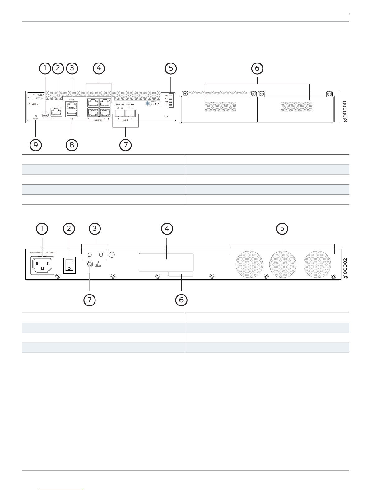
Figure 1: Front Panel Components of NFX150-S1
5—System status LEDs
6—1— Expansion module slotsMini USB console Port
7—2— Two 1-Gigabit Ethernet/10-Gigabit Ethernet SFP+ WAN portsRJ-45 console port
8—3— USB 3.0 portOne 10/100/1000BASE-T RJ-45 management port
9—4— Reset buttonFour 10/100/1000BASE-T RJ-45 LAN ports
Figure 2: Rear Panel Components of NFX150-S1
5—1— FansAC power cord inlet
6—2— CLEI codePower switch
7—3— Electrostatic discharge (ESD) pointGrounding point
4—Serial number
Mount an NFX150-S1 Device on Two Posts of a Rack
To mount an NFX150-S1 device on a rack, you require the parts that are shipped with the device along with the following additional
parts and equipment. These are not shipped with the device.
•
Electrostatic discharge (ESD) grounding strap
•
Four screws to secure the chassis and mounting bracket to the rack
•
Phillips (+) screwdriver, number 2
•
Management host, such as a PC or laptop, with a serial port
•
Grounding cable (minimum 14 AWG (2 mm²), minimum 90°C wire), grounding lug (Panduit LCC10-14BWL or equivalent), a
pair of 10-32x.25-in. screws, and a pair of flat washers
Copyright © 2018, Juniper Networks, Inc.2
Page 3
g100014
NFX150-S1 Network Services Platform Quick Start
For information about installing the grounding cable, see the NFX150 Hardware Guide available at:
https://www.juniper.net/documentation/en_US/release-independent/junos/information-products/pathway-pages/nfx-series/product/
You can mount an NFX150-S1 device on two posts of a 19-in. rack by using the mounting brackets provided with the device. To
install NFX150-S1 on two posts of a 23-in. rack, you need additional mounting brackets.
NOTE: The device weighs approximately 13 lb (5.9 kg). Two persons are required for mounting the device.
NOTE: Ensure that the rack is in its permanent location, allowing adequate clearance for airflow and maintenance,
and secured to the building structure.
NOTE: If you are mounting multiple units in the rack, mount the heaviest unit at the bottom and mount the other
units from bottom to top in the order of decreasing weight.
CAUTION: Wrap and fasten one end of the ESD grounding strap around your wrist and connect the other end to a
site ESD point.
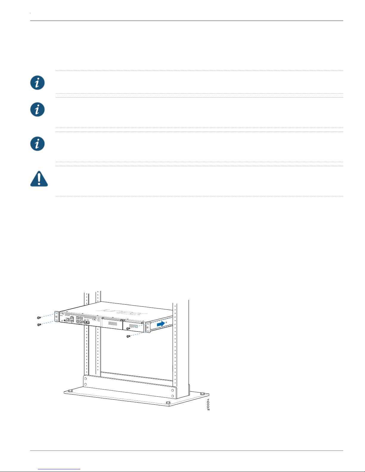
To mount the device on a rack:
1. Align the mounting brackets along the front or rear of the side panels of the chassis— depending on whether you will front-mount
or rear-mount the device—and attach the mounting brackets to the chassis by using the mounting bracket screws. Tighten
the screws.
2. Have one person grasp both sides of the device, lift the device, and position it in the rack, aligning the mounting bracket holes
with the threaded holes in the rack rail. Align the bottom hole in each mounting bracket with a hole in each rack rail, making
sure that the chassis is level.
Figure 3: Mounting the Device on Two Posts of a Rack
3. Have the second person use the rack-mounting screws (and cage nuts and washers if your rack requires them) to attach the
mounting brackets to the rack.
3Copyright © 2018, Juniper Networks, Inc.
Page 4

NFX150-S1 Network Services Platform Quick Start
Connect Power to the Device
CAUTION: Wrap and fasten one end of the ESD grounding strap around your wrist and connect the other end to a
site ESD point.
NOTE: Ensure that you ground AC-powered systems by attaching one end of the grounding cable to earth ground
and the other end to the chassis grounding points.
To connect the device to the power supply:
1. Set the power switch on the device to the off (O) position.
2. Insert the power cord plug into the power source outlet and power cord coupler into the chassis power inlet.
3. Set the power switch to the on (|) position.
4. Verify that the power LED is lit green and on steadily.
Power Cable Warning (Japanese)
WARNING: The attached power cable is only for this product. Do not use this cable for another product.
Factory-Default Settings
The NFX150 device is shipped with the following factory-default settings:
Table 1: Security Policies
Policy ActionDestination ZoneSource Zone
permittrusttrust
permituntrusttrust
Table 2: Interface Mapping
IP AddressDHCP StateSecurity ZoneVirtual InterfaceInterfacePort Label
192.168.2.1/24Servertrustge-0/0/0 to ge-0/0/3heth-0-0 to heth-0-30/0 to 0/3
ISP assignedClientuntrustge-1/0/1heth-0-40/4
ISP assignedClientuntrustge-1/0/2heth-0-50/5
Copyright © 2018, Juniper Networks, Inc.4
Page 5

NFX150-S1 Network Services Platform Quick Start
Table 2: Interface Mapping (continued)
IP AddressDHCP StateSecurity ZoneVirtual InterfaceInterfacePort Label
192.168.1.1/24N/AN/AN/Afxp0MGMT
Table 3: LTE Interfaces
IP AddressSecurity ZoneInterface
N/AN/Acl-1/1/0
ISP assigneduntrustdl0 (logical)
The NFX150 device is shipped with the following services enabled by default: DHCP, HTTPS, and TFTP.
To provide secure traffic, a basic set of screens are configured on the untrust zone.
Access the Device
1. Ensure that the NFX150 device is powered on.
2. Connect to the console port:
a. Plug one end of the Ethernet cable into the console port on your NFX150 device.
b. Connect the other end of the Ethernet cable to the RJ-45—to—DB-9 serial port adapter shipped with your device.
c. Connect the RJ-45—to—DB-9 serial port adapter to the serial port on the management device. Use the following values
to configure the serial port:
Baud rate—9600; Parity—N; Data bits—8; Stop bits—1; Flow control—None.
NOTE: Alternately, you can use the USB cable to connect to the mini-USB console port on the device. To use the
mini-USB console port, you must downloadthe USB driver from the following page and install it on the management
device:
https://www.juniper.net/support/downloads/junos.html
3. Use any terminal emulation program, such as HyperTerminal, to connect to the device console. The CLI displays a login prompt.
4. Log in as root and enter the password juniper123. If the software completes booting before you connect to the console, you
might need to press the Enter key for the prompt to appear:
login: root
password: juniper123
5. Start the CLI:
root@:~ # cli
root@>
6. Enter configuration mode:
root@> configure
[edit]
5Copyright © 2018, Juniper Networks, Inc.
Page 6

g100075
Internet
NFX150-S1 Network Services Platform Quick Start
root@#
7. Change the password for the root administration user account:
[edit]
root@# set system root-authentication plain-text-password
New password: password
Retype new password: password
8. Enable SSH service for the root user:
[edit]
root@# set system services ssh root-login allow
9. (Optional) Enable WAN connection for devices connected on LAN:
[edit]
root@# set access address-assignment pool junosDHCPPool family inet dhcp-attributes name-server dns-server-ip
10. Commit the configuration:
[edit]
root@# commit
Establish the Connection
1. Connect the device to the Internet Service Provider (ISP) by using the following step:
NOTE: For information on interface mapping, see Table 2 and Table 3.
Connect one of the WAN ports such as heth-0-4 or heth-0-5 to the ISP. The device is assigned an IP address by the ISP through
DHCP.
Figure 4: Connecting the Interfaces on an NFX150-S1 Device
Optionally, you can obtain a SIM card from the ISP and connect the device through LTE.
NOTE: The LTE expansion module must be purchased separately.
For more information about SIM card activation, see the Getting Started with NFX150 available at:
https://www.juniper.net/documentation/en_US/release-independent/junos/information-products/pathway-pages/nfx-series/product/
Copyright © 2018, Juniper Networks, Inc.6
Page 7

NFX150-S1 Network Services Platform Quick Start
2. Connect the laptop to one of the front panel LAN ports such as heth-0-0, heth-0-1, heth-0-2, or heth-0-3. The laptop is assigned
an IP address by the DHCP server running on the interface.
3. Open a browser on your laptop, navigate to https://www.juniper.net, and verify your connectivity.
Next Steps
For information on downloading the image, provisioning virtual network functions (VNFs), and performing initial configuration
using the CLI, see the Getting Started with NFX150 available at:
https://www.juniper.net/documentation/en_US/release-independent/junos/information-products/pathway-pages/nfx-series/product/
Safety Warnings Summary
This is a summary of safety warnings. For a complete list of warnings, including translations, see the NFX150 documentation at
https://www.juniper.net/documentation/en_US/release-independent/junos/information-products/pathway-pages/nfx-series/product/.
WARNING: Failure to observe the following safety warnings can result in personal injury or death:
•
Permit only trained and qualified personnel to install or replace device components.
•
Perform only the procedures described in this Quick Start Guide and the NFX150 documentation. Other services
must be performed only by authorized service personnel.
•
Before installing the device, read the planning instructions in the NFX150 documentation to make sure that the
site meets power, environmental, and clearance requirements for the device.
•
Before connecting the device to a power source, read the installation instructions in the NFX150 documentation.
•
The NFX150 device weighs approximately 13 lb (5.9 kg). Manually installing the device in a rack at a height above
60 in. (152.4 cm) requires two persons; one to lift the device and the second to install the mounting screws. To
prevent injury while lifting, keep your back straight and lift with your legs, not your back.
•
If the rack has stabilizing devices, install them in the rack before mounting or servicing the device in the rack.
•
Before installing or after removing an electrical component, always place it component-side up on an antistatic
mat placed on a flat, stable surface or in an antistatic bag.
•
Do not work on the device or connect or disconnect cables during electrical storms.
•
Before working on equipment that is connected to power lines, remove jewelry, including rings, necklaces, and
watches. Metal objects heat up when connected to power and ground and can cause serious burns or become
welded to the terminals.
Reference
•
Technical Support
https://www.juniper.net/support/requesting-support.html
•
Getting Started with NFX150
https://www.juniper.net/documentation/en_US/release-independent/junos/information-products/pathway-pages/nfx-series/product/
•
NFX150 Hardware Guide
https://www.juniper.net/documentation/en_US/release-independent/junos/information-products/pathway-pages/nfx-series/product/
•
Supported Transceivers
https://apps.juniper.net/hct/product/#prd=NFX150
7Copyright © 2018, Juniper Networks, Inc.
Page 8

NFX150-S1 Network Services Platform Quick Start
Juniper Networks, the Juniper Networks logo, Juniper, and Junos are registered trademarks of Juniper Networks, Inc. and/or its affiliates in the United States
and other countries. All other trademarks may be property of their respective owners. Juniper Networks assumes no responsibility for any inaccuracies in this
document. Juniper Networks reserves the right to change, modify, transfer, or otherwise revise this publication without notice. Copyright © 2018 Juniper
Networks, Inc. All rights reserved. Part Number: 530-083997 Rev. 01, March 2018.
 Loading...