

Page 1

Network Configuration Example
Published
2021-01-15
Network Segmentation using Device
Profiling with EX Series Switches and Aruba
ClearPass Policy Manager
Page 2

Juniper Networks, Inc.
1133 Innovation Way
Sunnyvale, California 94089
USA
408-745-2000
www.juniper.net
Juniper Networks, the Juniper Networks logo, Juniper, and Junos are registered trademarks of Juniper Networks, Inc. in
the United States and other countries. All other trademarks, service marks, registered marks, or registered service marks
are the property of their respective owners.
Juniper Networks assumes no responsibility for any inaccuracies in this document. Juniper Networks reserves the right
to change, modify, transfer, or otherwise revise this publication without notice.
Network Configuration Example Network Segmentation using Device Profiling with EX Series Switches and Aruba ClearPass
Policy Manager
Copyright © 2021 Juniper Networks, Inc. All rights reserved.
The information in this document is current as of the date on the title page.
ii
YEAR 2000 NOTICE
Juniper Networks hardware and software products are Year 2000 compliant. Junos OS has no known time-related
limitations through the year 2038. However, the NTP application is known to have some difficulty in the year 2036.
END USER LICENSE AGREEMENT
The Juniper Networks product that is the subject of this technical documentation consists of (or is intended for use with)
Juniper Networks software. Use of such software is subject to the terms and conditions of the End User License Agreement
(“EULA”) posted at https://support.juniper.net/support/eula/. By downloading, installing or using such software, you
agree to the terms and conditions of that EULA.
Page 3

Table of Contents
1
Device Profiling with EX Series Switches and Aruba ClearPass Policy Manager
About This Network Configuration Example | 5
Use Case Overview | 5
Technical Overview | 6
Configuring Device Profiling to provide Dynamic Segmentation with EX Series Switches
and Aruba ClearPass Policy Manager | 7
Configuring Colorless Ports on EX Series Switches with Aruba ClearPass Policy Manager
and Cisco ISE | 43
iii
Page 4

1
CHAPTER
Device Profiling with EX Series
Switches and Aruba ClearPass Policy
Manager
About This Network Configuration Example | 5
Use Case Overview | 5
Technical Overview | 6
Configuring Device Profiling to provide Dynamic Segmentation with EX Series
Switches and Aruba ClearPass Policy Manager | 7
Configuring Colorless Ports on EX Series Switches with Aruba ClearPass Policy
Manager and Cisco ISE | 43
Page 5

About This Network Configuration Example
This Network Configuration Example (NCE) describes how to configure a Juniper Networks EX Series
Ethernet Switch and Aruba ClearPass Policy Manager to authenticate wired endpoints that connect to EX
Series switches. Specifically, it shows how to configure an EX Series switch and Aruba ClearPass to profile
endpoints in authentication process and use the device profiling information to determine access policy.
The colorless port concept rely on device profiling to return the appropriate VLAN/policy. All ports have
the same configuration (colorless) and based on the device type connected (AP, IP camera, or printer),
NAC (ClearPass) will return the appropriate VLAN/role.
Use Case Overview
5
Juniper Networks EX Series Ethernet Switches are designed to meet the demands of today’s
high-performance businesses. They enable companies to grow their networks at their own pace, minimizing
large up-front investments. Based on open standards, EX Series switches provides:
Carrier-class reliability
•
Security risk management
•
Virtualization
•
Application control
•
Lower total cost of ownership (TCO
•
•
Also, allow businesses to scale in an economically sensible way for years to come.
Aruba ClearPass Policy Manager is a policy management platform that provides role-based and device-based
network access control (NAC) for any user across any wired, wireless, and VPN infrastructure. Enterprises
can deploy EX Series switches can leverage the extensive RADIUS capabilities on EX Series switches to
integrate with Aruba ClearPass. This integration enables enterprises to deploy consistent security policies
across their wired and wireless infrastructure.
Enterprises typically have a variety of users and endpoints, which results in multiple use cases that need
to be addressed by their policy infrastructure. Depending on the type of endpoint and how it is being used,
an endpoint might be authenticated by 802.1X authentication, MAC RADIUS authentication, or captive
portal authentication. The policy infrastructure enables any device to be connected to any port on the
access switch, and authenticates based on the type of device, the authorization level of the user, or both.
Page 6

In this network configuration example, we show how to configure Juniper Networks EX Series switches
and Aruba ClearPass Policy Manager to use device profiling as part of the authentication process. Device
profiling enables Aruba ClearPass to determine the type of endpoint that is being authenticated (for
example, whether it is an access point or a VoIP phone or a Windows computer) and then use that
information to enforce access policy appropriate to the device type.
Technical Overview
Aruba ClearPass profiling is part of the ClearPass Policy Manager module that performs device profiling.
Profiling is enabled by default and automatically collects a variety of data about endpoints, analyzes the
data to classify the endpoints, and stores the classifications as device profiles in an endpoint repository.
Use the device profiles in enforcement policies to control access to your network. For example, create an
enforcement policy that grants endpoints profiled as VoIP phones access to specific servers in your network.
Or, create an enforcement policy that places all endpoints profiled as access points in a specific VLAN.
6
A device profile classifies an endpoint according to the following three hierarchical elements:
Category—This is the broadest classification of a device. It denotes the type of the device. For example:
•
access point, VoIP phone, printer, computer, or smart device.
Family—Devices within a category are organized into families based on type of OS or type of vendor.
•
For example, when the device category is computer, the family might be Windows, Linux, or Mac OS X.
When the device category is smart device, the family might be Apple or Android.
Name—Devices within a family are further organized by more granular details, such as version. For
•
example, when the device family is Windows, the device name might be Windows 10 or Windows 2008
server.
In addition to the hierarchical classification above, a device profile contain information such as IP address,
hostname, vendor, and time when the device was first discovered or when it was last seen.
To profile devices, Aruba ClearPass Profile uses a number of different types of collectors to collect data
on endpoints. For a complete list of the kinds of collectors used. This network configuration example relies
on data provided by the DHCP and MAC Organizationally Unique Identifier (OUI) collectors:
DHCP collector—Collects DHCP attributes such as option55 (parameter request list), option60 (vendor
•
class), and options list from DHCPDiscover and DHCPRequest packets. This information can uniquely
fingerprint most endpoints that use DHCP to acquire an IP address on the network. DHCP packets also
provide the hostname and IP address of a device.
For the DHCP collector to be able to collect this information, Aruba ClearPass must receive DHCP
packets from the endpoints. DHCP relay on EX Series switches allows a switch to send the initial
DHCPDiscover and DHCPRequest packets from endpoints to more than one receiver. Configuring
Page 7
ClearPass as one of these receivers allows ClearPass to listen in on the DHCP message exchange between
the DHCP servers and client endpoints and to collect the required information from the DHCP packets.
MAC OUI collector—Collects the OUI portion of a device’s MAC address. The MAC OUI can be used
•
to better classify some endpoints. For example, DHCP fingerprinting can classify an endpoint as a generic
Android device, but it cannot provide information about the vendor. By using the MAC OUI in addition
to DHCP fingerprinting, ClearPass Profile can classify an Android device as an HTC Android device, a
Samsung Android device, a Motorola Android device, and so on. ClearPass Profile can also use the MAC
OUI to profile devices such as printers that might have static IP addresses.
The MAC OUI collector obtains the MAC OUI from the MAC address information included in the RADIUS
request packets sent from the EX Series switch on behalf of the endpoint.
Configuring Device Profiling to provide Dynamic
Segmentation with EX Series Switches and Aruba
7
ClearPass Policy Manager
IN THIS SECTION
Requirements | 8
Overview and Topology | 9
Configuration | 10
Dynamic Segmentation provides the flexibility of assigning wired ports on EX switches with dynamic VLAN
and policies to segment the internet of things (IOT), access point traffic, and wired user traffic. Aruba
ClearPass can centrally manage and enforce network access polices for wired and wireless control.
Micro segmentation is obtained by applying dynamic firewall filters to the wired ports once we successfully
authenticate the device to control the east-west traffic. With dynamic filters we can control in a camera
network so that it talks only to the secured camera recording server or few dedicated terminals used by
security personals. Similarly, we can apply firewall filters on the IP Phone network to allow communication
between IP phones and call manager server in the network.
This configuration example illustrates how to use the features of EX Series switches and Aruba ClearPass
Policy Manager to perform device profiling as part of the endpoint authentication process.
Page 8

In this example, an organization has four types of endpoints in its wired infrastructure for which it has
defined access policies:
Access points—Endpoints profiled as access points are allowed access to the network and are dynamically
•
assigned to the AP_VLAN VLAN.
IP phones—Endpoints profiled as IP phones are allowed access to the network. The IPPhone_VLAN is
•
dynamically assigned as the VoIP VLAN.
Corporate laptops—Endpoints that have an 802.1X supplicant are authenticated by the user credentials.
•
After the user is successfully authenticated, the laptop is granted access to the network and placed in
the Employee_VLAN VLAN.
Camera /IOT Devices—Camera and IOT devices having or not having 802.1x supplicants can be added
•
to the network and granted access to the Camera_IOT_VLAN VLAN.
Noncorporate laptops/Tablets—Endpoints that do not have an 802.1X supplicant and that are profiled
•
as non-corporate devices are provided only internet access
Table 1 on page 8 shows the defines values of the access policies for wired, wireless, and authorization.
8
Table 1: Access Policies Details
130 (NATIVE)AP VLAN
Requirements
121,131,151,102
121120IP-Phone
AuthorizationWirelessWiredAccess Policies
-ALLOWED VLAN =
Between phones and call manager
server
Access all151150Employee
Quarantine102101Remediation
DHCP, NTP, and NVR131130IOT Camera
This example the following hardware and software components for the policy infrastructure:
EX4300, EX2300, EX3400 switch running Junos OS Release 20.2R1 or earlier
•
Aruba ClearPass Policy Manager running 6.9.0.130064
•
Page 9

Overview and Topology
To implement the endpoint access policies, the policy infrastructure is configured as follows:
All access interfaces on the switch are initially configured to be in VLAN 100, which serves as a
•
remediation VLAN. If an endpoint is not successfully authenticated or is not successfully profiled as one
of the supported endpoints, it remains in the remediation VLAN.
NOTE: When the endpoints utilize DHCP, avoid changing the VLANs. The endpoint will not
send another DHCPRequest until their existing lease expires or a port bounce occurs.
Endpoints that have an 802.1X supplicant are authenticated by using 802.1X PEAP authentication. For
•
more information on 802.1X PEAP authentication, see Configuring 802.1X PEAP and MAC RADIUS
Authentication with EX Series Switches and Aruba ClearPass Policy Manager.
Endpoints that do not have an 802.1X supplicant are authenticated using MAC RADIUS authentication
•
and are profiled to determine what type of device they are. These endpoints undergo a two-step
authentication process:
9
1. The first step occurs after an endpoint first connects to the switch but before it has been profiled by
Aruba ClearPass Profile. After it connects, the endpoint is authenticated using MAC RADIUS
authentication. Aruba ClearPass applies an enforcement policy that instructs the switch to grant the
endpoint access to the Internet but prevents it from accessing the internal network.
2. The second step occurs after an endpoint has been successfully profiled. After being authenticated
in the first step, the endpoint contacts a DHCP server to request an IP address. The switch relays
the DHCP messages sent by the endpoint to the DHCP server to Aruba ClearPass as well, which
allows ClearPass to profile the endpoint. After it has profiled the endpoint and added the endpoint
to its endpoint repository, ClearPass sends a RADIUS Change of Authorization (CoA) message to the
switch, telling it to terminate the session. The switch then attempts reauthentication on behalf of
the endpoint. Because the endpoint now exists in the endpoint repository, Aruba ClearPass is able
to apply an enforcement policy appropriate to the device type when it authenticates the endpoint.
For example, if the endpoint is an access point, ClearPass applies the enforcement policy that
dynamically assigns the access point to the AP_VLAN VLAN.
Figure 1 on page 10 shows the topology used in this example.
Page 10
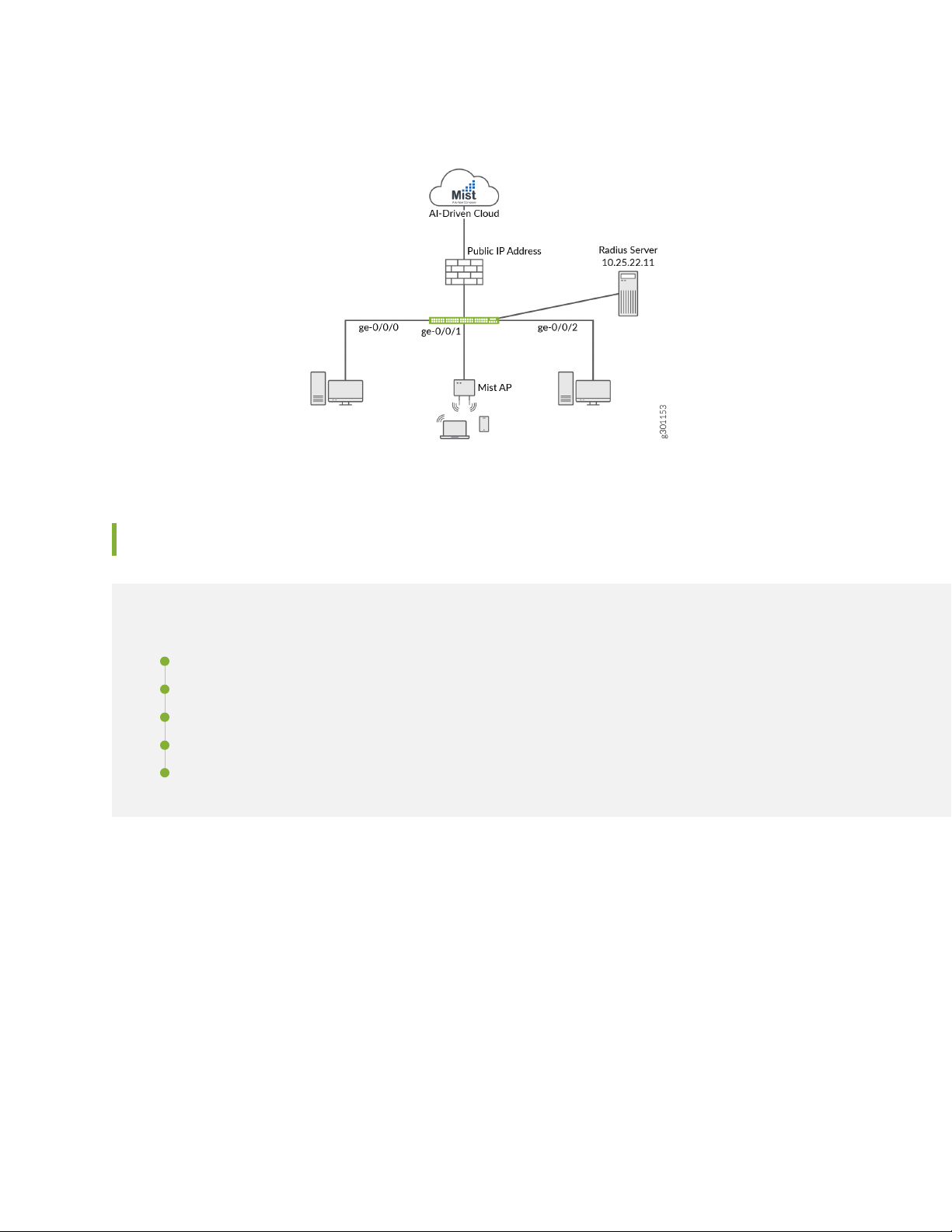
Figure 1: Topology Used in This Example
10
Configuration
IN THIS SECTION
Configuring the EX Switch | 10
Configuring Aruba ClearPass Policy Manager | 19
Verification | 34
Monitoring Device Profiling | 40
Troubleshooting Authentication | 43
This section provides step-by-step instructions for:
Configuring the EX Switch
CLI Quick Configuration
To quickly configure this example, copy the following commands, paste them in a text file, remove any
line breaks, change any details necessary to match your network configuration, copy and paste the
commands into the CLI at the [edit] hierarchy level, and then enter commit from configuration mode.
Page 11

[edit]
set access radius-server 10.25.22.11 dynamic-request-port 3799
set access radius-server 10.25.22.11 secret "$9$tqCW01hevLVwgSrwgoJHkp0BISrKM87db"
set access radius-server 10.25.22.11 source-address 10.25.99.11
set access profile ACCESS_PROF_RADIUS accounting-order radius
set access profile ACCESS_PROF_RADIUS authentication-order radius
set access profile ACCESS_PROF_RADIUS radius authentication-server 10.25.22.11
set access profile ACCESS_PROF_RADIUS radius accounting-server 10.25.22.11
set protocols dot1x authenticator authentication-profile-name ACCESS_PROF_RADIUS
set protocols dot1x authenticator interface AUTHC supplicant multiple
set protocols dot1x authenticator interface AUTHC transmit-period 3
set protocols dot1x authenticator interface AUTHC mac-radius
set vlans AP vlan-id 130
set vlans EMPLOYEE-WIRED vlan-id 150
set vlans EMPLOYEE-WIRELESS vlan-id 151
set vlans IOT-WIRED vlan-id 111
set vlans IOT-WIRELESS vlan-id 112
set vlans IP-PHONE-WIRED vlan-id 120
set vlans IP-PHONE-WIRELESS vlan-id 121
set vlans MANAGEMENT vlan-id 99
set vlans MANAGEMENT l3-interface irb.99
set vlans REMEDIATION-WIRED vlan-id 101
set vlans REMEDIATION-WIRELESS vlan-id 102
set interfaces interface-range AP member ge-0/0/0
set interfaces interface-range AP native-vlan-id 130
set interfaces interface-range AP unit 0 family ethernet-switching interface-mode
trunk
set interfaces interface-range AP unit 0 family ethernet-switching vlan members AP
set interfaces interface-range AP unit 0 family ethernet-switching vlan members
EMPLOYEE-WIRELESS
set interfaces interface-range AUTHC member ge-0/0/6
set interfaces interface-range AUTHC member ge-0/0/3
set interfaces interface-range AUTHC member ge-0/0/2
set interfaces interface-range AUTHC member ge-0/0/4
set interfaces interface-range AUTHC member ge-0/0/7
set interfaces interface-range AUTHC member ge-0/0/8
set interfaces interface-range AUTHC member ge-0/0/9
set interfaces interface-range AUTHC member ge-0/0/5
set interfaces interface-range AUTHC unit 0 family ethernet-switching interface-mode
access
set interfaces interface-range AUTHC unit 0 family ethernet-switching vlan members
REMEDIATION-WIRED
set firewall family ethernet-switching filter Internet_Only_Access term Allow_DHCP
from destination-port 67
11
Page 12

set firewall family ethernet-switching filter Internet_Only_Access term Allow_DHCP
from destination-port 68
set firewall family ethernet-switching filter Internet_Only_Access term Allow_DHCP
from ip-protocol udp
set firewall family ethernet-switching filter Internet_Only_Access term Allow_DHCP
then accept
set firewall family ethernet-switching filter Internet_Only_Access term Allow_DNS
from destination-port 53
set firewall family ethernet-switching filter Internet_Only_Access term Allow_DNS
from ip-protocol udp
set firewall family ethernet-switching filter Internet_Only_Access term Allow_DNS
from ip-protocol tcp
set firewall family ethernet-switching filter Internet_Only_Access term Block_Internal
from ip-destination-address 192.168.0.0/16
set firewall family ethernet-switching filter Internet_Only_Access term Block_Internal
then discard
set firewall family ethernet-switching filter Internet_Only_Access term Allow_All
then accept
12
Step-by-Step Procedure
The general steps to configure the EX switch are:
Configure the connection to the Aruba ClearPass Policy Manager.
•
Create the access profile used by the 802.1X protocol. The access profile tells the 802.1X protocol which
•
authentication server and authentication methods to use and the order of the authentication methods.
Configure the 802.1X protocol.
•
Configure the VLANs.
•
Configure Ethernet switching on the access ports.
•
Configure integrated routing and bridging (IRB) interfaces and assign them to the VLANs.
•
Configure DHCP relay to send DHCP packets to Aruba ClearPass so that it can perform device profiling.
•
Create the firewall policy that blocks access to the internal network.
•
To configure the EX switch:
1. Provide the RADIUS server connection information..
[edit]
user@Policy-EX-switch# set access radius-server 10.25.22.11 dynamic-request-port
3799
user@Policy-EX-switch# set access radius-server 10.25.22.11 secret password
Page 13

user@Policy-EX-switch# set access radius-server 10.25.22.11 source-address
10.25.99.11
2. Configure the access profile.
[edit access]
user@Policy-EX-switch# set access profile ACCESS_PROF_RADIUS accounting-order
radius
user@Policy-EX-switch# set access profile ACCESS_PROF_RADIUS authentication-order
radius
user@Policy-EX-switch# set access profile ACCESS_PROF_RADIUS radius
authentication-server 10.25.22.11
user@Policy-EX-switch# set access profile ACCESS_PROF_RADIUS radius
accounting-server 10.25.22.11
3. Configure 802.1X to use ACCESS_PROF_RADIUS and enable the protocol on each access interface.
In addition, configure the interfaces to support MAC RADIUS authentication and to allow more than
one supplicant, each of which must be individually authenticated.
13
By default, the switch will first attempt 802.1X authentication. If it receives no EAP packets from the
endpoint, indicating that the endpoint does not have an 802.1X supplicant, it then tries MAC RADIUS
authentication.
[edit]
user@Policy-EX-switch# set protocols dot1x authenticator
authentication-profile-name ACCESS_PROF_RADIUS
user@Policy-EX-switch# set protocols dot1x authenticator interface AUTHC supplicant
multiple
user@Policy-EX-switch# set protocols dot1x authenticator interface AUTHC
transmit-period 3
user@Policy-EX-switch# set protocols dot1x authenticator interface AUTHC mac-radius
user@Policy-EX-switch# set interfaces interface-range AP member ge-0/0/0
user@Policy-EX-switch# set interfaces interface-range AP native-vlan-id 130
user@Policy-EX-switch# set interfaces interface-range AP unit 0 family
ethernet-switching interface-mode trunk
user@Policy-EX-switch# set interfaces interface-range AP unit 0 family
ethernet-switching vlan members AP
user@Policy-EX-switch# set interfaces interface-range AP unit 0 family
ethernet-switching vlan members EMPLOYEE-WIRELESS
user@Policy-EX-switch# set interfaces interface-range AUTHC member ge-0/0/6
user@Policy-EX-switch# set interfaces interface-range AUTHC member ge-0/0/3
user@Policy-EX-switch# set interfaces interface-range AUTHC member ge-0/0/2
Page 14

user@Policy-EX-switch# set interfaces interface-range AUTHC member ge-0/0/4
user@Policy-EX-switch# set interfaces interface-range AUTHC member ge-0/0/7
user@Policy-EX-switch# set interfaces interface-range AUTHC member ge-0/0/8
user@Policy-EX-switch# set interfaces interface-range AUTHC member ge-0/0/9
user@Policy-EX-switch# set interfaces interface-range AUTHC member ge-0/0/5
4. Configure the VLANs used in this example.
[edit]
user@Policy-EX-switch# set vlans AP vlan-id 130
user@Policy-EX-switch# set vlans EMPLOYEE-WIRED vlan-id 150
user@Policy-EX-switch# set vlans EMPLOYEE-WIRELESS vlan-id 151
user@Policy-EX-switch# set vlans IOT-WIRED vlan-id 111
user@Policy-EX-switch# set vlans IOT-WIRELESS vlan-id 112
user@Policy-EX-switch# set vlans IP-PHONE-WIRED vlan-id 120
user@Policy-EX-switch# set vlans IP-PHONE-WIRELESS vlan-id 121
user@Policy-EX-switch# set vlans MANAGEMENT vlan-id 99
user@Policy-EX-switch# set vlans MANAGEMENT l3-interface irb.99
user@Policy-EX-switch# set vlans REMEDIATION-WIRED vlan-id 101
user@Policy-EX-switch# set vlans REMEDIATION-WIRELESS vlan-id 102
14
Note that for dynamic VLAN assignment to work, the VLAN must exist on the switch before
authentication is attempted. If the VLAN doesn’t exist, authentication fails.
5. Configure DHCP relay to forward DHCP request packets to Aruba ClearPass.
[edit]
user@Policy-EX-switch# set dhcp-relay server-group dhcp-dot1x 10.25.22.11
user@Policy-EX-switch# set dhcp-relay active-server-group dhcp-dot1x
6. Configure a firewall filter, Internet_Only_Access, to be used for devices that have been authenticated
by MAC RADIUS authentication but have not yet been profiled.
This filter blocks an endpoint from accessing the internal network (192.168.0.0/16).
[edit]
user@Policy-EX-switch# set firewall family ethernet-switching filter
INTERNET_ACCESS_ONLY term ALLOW_DHCP from destination-port 67
user@Policy-EX-switch# set firewall family ethernet-switching filter
INTERNET_ACCESS_ONLY term ALLOW_DHCP from destination-port 68
user@Policy-EX-switch# set firewall family ethernet-switching filter
INTERNET_ACCESS_ONLY term ALLOW_DHCP from ip-protocol udp
Page 15

user@Policy-EX-switch# set firewall family ethernet-switching filter
INTERNET_ACCESS_ONLY term ALLOW_DHCP then accept
user@Policy-EX-switch# set firewall family ethernet-switching filter
INTERNET_ACCESS_ONLY term ALLOW_DNS from destination-port 53
user@Policy-EX-switch# set firewall family ethernet-switching filter
INTERNET_ACCESS_ONLY term ALLOW_DNS from ip-protocol udp
user@Policy-EX-switch# set firewall family ethernet-switching filter
INTERNET_ACCESS_ONLY term ALLOW_DNS from ip-protocol tcp
user@Policy-EX-switch# set firewall family ethernet-switching filter
INTERNET_ACCESS_ONLY term BLOCK_RFC_1918 from ip-destination-address 10.0.0.0/8
user@Policy-EX-switch# set firewall family ethernet-switching filter
INTERNET_ACCESS_ONLY term BLOCK_RFC_1918 from ip-destination-address 172.16.0.0/12
user@Policy-EX-switch# set firewall family ethernet-switching filter
INTERNET_ACCESS_ONLY term BLOCK_RFC_1918 from ip-destination-address 192.168.0.0/16
user@Policy-EX-switch# set firewall family ethernet-switching filter
INTERNET_ACCESS_ONLY term BLOCK_RFC_1918 then discard
user@Policy-EX-switch# set firewall family ethernet-switching filter
INTERNET_ACCESS_ONLY term ALLOW_ALL then accept
15
Results
From configuration mode, confirm your configuration by entering the following show commands.
user@Policy-EX-switch# show access
radius-server {
10.25.22.11 {
dynamic-request-port 3799;
secret "$9$tqCW01hevLVwgSrwgoJHkp0BISrKM87db"; ## SECRET-DATA
source-address 10.25.99.11;
}
}
profile ACCESS_PROF_RADIUS {
accounting-order radius;
authentication-order radius;
radius {
authentication-server 10.25.22.11;
accounting-server 10.25.22.11;
}
}
}
Page 16

user@Policy-EX-switch# show protocols
dot1x {
authenticator {
authentication-profile-name ACCESS_PROF_RADIUS;
interface {
AUTHC {
supplicant multiple;
transmit-period 3;
mac-radius;
}
}
}
}
user@Policy-EX-switch# show interfaces
interface-range AP {
member ge-0/0/0;
native-vlan-id 130;
unit 0 {
family ethernet-switching {
interface-mode trunk;
vlan {
members [ AP EMPLOYEE-WIRELESS ];
}
}
}
}
interface-range AUTHC {
member ge-0/0/6;
member ge-0/0/3;
member ge-0/0/2;
member ge-0/0/4;
member ge-0/0/7;
member ge-0/0/8;
member ge-0/0/9;
member ge-0/0/5;
unit 0 {
family ethernet-switching {
interface-mode access;
vlan {
members REMEDIATION-WIRED;
16
Page 17

}
}
}
}
user@Policy-EX-switch# show vlans
AP {
vlan-id 130;
}
EMPLOYEE-WIRED {
vlan-id 150;
}
EMPLOYEE-WIRELESS {
vlan-id 151;
}
IOT-WIRED {
vlan-id 111;
}
IOT-WIRELESS {
vlan-id 112;
}
IP-PHONE-WIRED {
vlan-id 120;
}
IP-PHONE-WIRELESS {
vlan-id 121;
}
MANAGEMENT {
vlan-id 99;
l3-interface irb.99;
}
REMEDIATION-WIRED {
vlan-id 101;
}
REMEDIATION-WIRELESS {
vlan-id 102;
}
}
}
17
Page 18

user@Policy-EX-switch# show forwarding-options
dhcp-relay {
server-group {
dhcp-dot1x {
10.25.22.11;
}
}
helpers {
bootp {
server 10.25.22.11;
}
}
user@Policy-EX-switch# show firewall
family ethernet-switching {
filter INTERNET_ACCESS_ONLY {
term ALLOW_DHCP {
from {
destination-port [ 67 68 ];
ip-protocol udp;
}
then accept;
}
term ALLOW_DNS {
from {
destination-port 53;
ip-protocol [ udp tcp ];
}
}
term BLOCK_RFC_1918 {
from {
ip-destination-address {
10.0.0.0/8;
172.16.0.0/12;
192.168.0.0/16;
}
}
then discard;
}
term ALLOW_ALL {
then accept;
}
18
Page 19

}
}
}
If you are done configuring the device, enter commit from configuration mode.
Configuring Aruba ClearPass Policy Manager
Step-by-Step Procedure
19
Page 20

The general steps for configuring Aruba ClearPass are:
Verify the Juniper-AV-Pair attribute exists in your RADIUS dictionary.
•
Add the EX switch as a network device.
•
Ensure that the server certificate used for 802.1X PEAP authentication has been installed.
•
Add the local user used in this example for 802.1X authentication.
•
Create the following enforcement profiles:
•
VLAN 150 ENF PROF that places endpoints in VLAN 150.
•
JUNIPER VOIP VLAN 120 ENF PROF that defines VLAN 120 as the VoIP VLAN.
•
VLAN 130 ENF PROF that places endpoints in VLAN 130.
•
Internet_Only_Access_Fliter_ID_ENF_Prof that specifies the firewall filter Internet_Only_Access be
•
used for devices that have not yet been profiled.
Create two enforcement policies:
•
20
A policy that is invoked when MAC RADIUS authentication is used.
•
A policy that is invoked when 802.1X authentication is used.
•
Define the MAC RADIUS authentication service and the 802.1X authentication service.
•
Ensure that the MAC RADIUS authentication service is evaluated before the 802.1X authentication
•
service.
To configure Aruba ClearPass:
Page 21

1. Verify the Juniper-AV-Pair attribute exists in your RADIUS dictionary.
Go to Administration > Dictionaries > RADIUS and Open the Juniper dictionary.
NOTE: If the Juniper dictionary is shown in red, open the Juniper dictionary page to enable
the dictionary and click the enable button.
21
If the Juniper-AV-Pair attribute is not present, follow these steps to add it:
a. Click the Export button.
Page 22

b. Save the RadiusDictionary.xml file to your computer and then open it with a text editor.
c. Under the RadiusAttributes section, add the following line:
<Attribute profile="in out" type="String" name="Juniper-AV-Pair" id="52"/>
d. Save the XML file.
e. Return to your ClearPass session and click on the Import button in the top right corner of the
RadiusDictionary page.
f. Click the Browse button and find the RadiusDictionary.xml file you just saved
22
Page 23

g. Click Import.
h. Now open the Juniper RADIUS dictionary and verify if the Juniper-AV-Pair attribute is present
2. Add the EX switch as a network device.
a. Under Configuration > Network > Devices, click Add.
23
b. On the Device tab, enter the hostname and IP address of the switch and the RADIUS shared secret
that you configured on the switch. Set the Vendor Name field to Juniper.
c. Ensure that a trusted server certificate for 802.1X PEAP authentication exists.
Page 24

Under Administration > Certificates > Certificate Store, verify that each Aruba ClearPass server
•
has a valid RADIUS/EAP Server Certificate installed. If they do not, add a valid server certificate.
The Aruba ClearPass documentation and your Certificate Authority can provide more details on
how to obtain certificates and import them into ClearPass.
d. Add a test user to the local user repository. This user will be used to verify 802.1X authentication.
Under Configuration > Identity > Local Users, click Add.
•
24
In the Add Local User window, enter the user ID (usertest1), username (Test User), and password.
•
Then select Employee as the user role. Under Attributes, select the Department attribute and
type Finance under value.
Page 25

NOTE: In this configuration example, the ClearPass Local User Repository is used as the
authentication source. In a typical enterprise deployment, however, Microsoft Active
Directory is used as the authentication source. For further detail on how to configure
Active Directory as an authentication source, search the ClearPass documentation located
in Administration » Support » Documentation.
3. Configure an enforcement profile for employee laptops or desktops that authenticate using 802.1X.
This profile places the endpoints in VLAN 150.
•
Under Configuration > Enforcement > Profiles, click Add.
a. On the Profile tab, set Template to VLAN Enforcement and type the profile name, VLAN 150 ENF
PROF, in the Name field.
25
Page 26

b. On the Attributes tab, configure the attributes as shown.
4. Configure an access point enforcement profile, which places access points in VLAN 130.
Use the same basic procedure to create this profile as you used in the previous step. After you
•
complete the profile, the information on the Summary tab will appear as shown.
26
5. Configure an IP phone enforcement profile.
This profile instructs Aruba ClearPass to return VLAN 120 as the VLAN that should be used as the
•
VoIP VLAN. The Juniper Networks RADIUS dictionary defines a special RADIUS attribute to use for
this purpose. Select RADIUS-Juniper for the attribute type and Juniper-VoIP-Vlan as the attribute
name.
Page 27

After you complete the profile, the information on the Summary tab will appear as shown.
•
6. Configure an Internet access only enforcement profile.
This enforcement profile tells Aruba ClearPass to return the name of the firewall filter
•
Internet_Only_Access, which is the firewall filter you configured on the switch that blocks access to
the internal network. After you complete this profile, the information on the Summary tab will appear
as shown.
27
Configure the MAC RADIUS authentication enforcement policy.
•
For endpoints being authenticated by MAC RADIUS authentication, this policy informs Aruba ClearPass
•
to apply enforcement policies according to the device profile. The VLAN 130 ENF PROF is applied
to endpoints profiled as access points, and the JUNIPER VOIP VLAN 120 ENF PROF is applied to
endpoints profiled as VoIP phones. The predefined enforcement policy [Deny Access Profile] is
applied to endpoints profiled as Windows devices. This enforces the organization access policy that
only laptops with an 802.1X supplicant are allowed access to the network. For all other endpoints,
including endpoints that have not yet been profiled, the INTERNET ONLY ACCESS FILTER ID ENF
PROF profile will be applied.
Page 28

Under Configuration > Enforcement > Policies, click Add.
•
On the Enforcement tab, type the name of the policy (JUNOS MAC AUTH ENF POL) and set Default
•
Profile to INTERNET ONLY ACCESS FILTER ID ENF PROF.
On the Rules tab, click Add Rule and add the rules shown.
•
You must add the rules sequentially by clicking Save before you create the next rule.
28
7. Configure the 802.1X enforcement policy.
This policy tells Aruba ClearPass to use the VLAN 150 ENF PROF enforcement profile if a user is
successfully authenticated as a member of the finance department. Any other user authentication will
match the Default Profile and the switch will be sent a RADIUS Accept and place the endpoint in the
remediation VLAN 100.
Under Configuration » Enforcement » Policies, click Add.
•
Page 29

On the Enforcement tab, type the name of the policy (JUNOS DOT1X ENF POL) and set Default
•
Profile to [Allow Access Profile].
On the Rules tab, click Add Rule and add the rule shown.
•
29
8. Configure the JUNOS MAC AUTH authentication service.
The configuration for this service results in MAC RADIUS authentication being performed when the
RADIUS User-Name attribute and the Client-MAC-Address attribute received have the same value.
Page 30
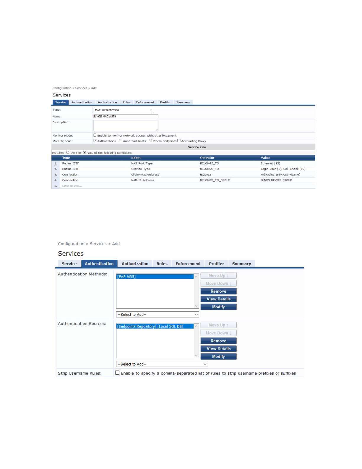
Under Configuration » Services, click Add.
•
On the Services tab, fill out the fields as shown. Be sure to select the Authorization and Profile
•
Endpoints options.
30
On the Authentication tab, delete [Allow All MAC AUTH] from the Authentication Methods list and
•
add [EAP MD5] to the list.
Select [Endpoints Repository] [Local SQL DB] in the Authentication Sources list.
Page 31

On the Enforcement tab, select JUNOS MAC AUTH ENF POL.
•
On the Profiler tab, add Computer, VoIP Phone, Access Points to the Endpoint Classification list.
•
31
Select [Juniper Terminate Session] from the RADIUS CoA Action list.
This configuration causes endpoints to go through reauthentication after they are profiled and added
to the endpoint repository. Before an endpoint is profiled, the INTERNET ONLY ACCESS FILTER ID
ENF PROF enforcement profile is in effect for the authenticated user session. (This profile is the
default profile for the MAC authentication policy configured in Step 7.) After Aruba ClearPass
successfully classifies a device, it sends a RADIUS CoA to the switch, which causes the switch to
terminate the session. The switch then attempts to reauthenticate the endpoint. Because the endpoint’s
device profile is now in the endpoint repository, the appropriate device enforcement profile will be
applied when the endpoint is authenticated.
Click Save.
•
9. Configure the 802.1X authentication service.
Page 32

Under Configuration > Services, click Add.
•
On the Service tab, fill out the fields as shown.
•
On the Authentication tab:
•
32
Set Authentication Sources to [Local User Repository][Local SQL DB].
•
Remove the [EAP FAST], [EAP-TLS] and [EAP-TTLS] Authentication Methods.
•
Page 33

On the Enforcement tab, set Enforcement Policy to Juniper_Dot1X_Policy.
•
33
Verify that the MAC RADIUS authentication service policy is evaluated before the 802.1X
•
authentication service policy.
Because Aruba ClearPass is configured to recognize MAC RADIUS authentication requests by the
•
RADIUS User-Name attribute and the Client-MAC-Address attribute having the same value, it is
more efficient to have the MAC RADIUS service policy evaluated first.
In the Services main window, verify that JUNOS MAC AUTH appears before JUNOS DOT1X in
•
the services list, as shown. If it does not, click Reorder and move JUNOS MAC AUTH above JUNOS
DOT1X.
Page 34

Verification
IN THIS SECTION
Verifying 802.1X Authentication on the EX Switch | 34
Verifying the Access Point Authentication on the EX Switch | 35
Verifying the VoIP Phone and Non-corporate Laptop Authentication on the EX Switch | 36
Verifying the Status of Authentication Requests on Aruba ClearPass Policy Manager | 38
Confirm that the configuration is working properly.
Verifying 802.1X Authentication on the EX Switch
Purpose
Verify that the test user, usertest1, is being authenticated and placed in the correct VLAN.
34
To perform this procedure, you must have a Windows device with an active 802.1X supplicant that passes
the authentication information for usertest1. For information on how to configure a Windows 7 supplicant
for 802.1X PEAP authentication, see Configuring 802.1X PEAP and MAC RADIUS Authentication with EX
Series Switches and Aruba ClearPass Policy Manager.
Action
1. Connect the Windows 7 laptop to ge-0/0/22 on the EX switch.
2. On the switch, type the following command:
user@Policy-EX-switch-01> show dot1x interface ge-0/0/8
802.1X Information:
Interface Role State MAC address User
ge-0/0/8.0 Authenticator Authenticated 98:90:96:D8:70:19 usertest1
3. For more details, including the dynamic VLAN assignment, type:
user@Policy-EX-switch-01> show dot1x interface ge-0/0/8 detail
ge-0/0/8.0
Role: Authenticator
Administrative state: Auto
Supplicant mode: Multiple
Page 35

Number of retries: 3
Quiet period: 60 seconds
Transmit period: 3 seconds
Mac Radius: Enabled
Mac Radius Restrict: Disabled
Mac Radius Authentication Protocol: EAP-MD5
Reauthentication: Enabled
Reauthentication interval: 3600 seconds
Supplicant timeout: 30 seconds
Server timeout: 30 seconds
Maximum EAPOL requests: 2
Guest VLAN member: not configured
Number of connected supplicants: 1
Supplicant: usertest1, 98:90:96:D8:70:19
Operational state: Authenticated
Backend Authentication state: Idle
Authentication method: Radius
Authenticated VLAN: EMPLOYEE-WIRED
Session Reauth interval: 10800 seconds
Reauthentication due in 10772 seconds
Eapol-Block: Not In Effect
Domain: Data
35
The output shows that usertest1 has been successfully authenticated and placed in the
EMPLOYEE-WIRED VLAN.
Verifying the Access Point Authentication on the EX Switch
Purpose
Verify that the access point has been successfully authenticated and placed in the correct VLAN.
Action
1. Connect an access point to ge-0/0/6 on the EX switch.
2. On the switch, type the following command:
user@Policy-EX-switch-01> show dot1x interface ge-0/0/6
ge-0/0/6.0
Role: Authenticator
Administrative state: Auto
Supplicant mode: Multiple
Number of retries: 3
Quiet period: 60 seconds
Page 36

Transmit period: 3 seconds
Mac Radius: Enabled
Mac Radius Restrict: Disabled
Mac Radius Authentication Protocol: EAP-MD5
Reauthentication: Enabled
Reauthentication interval: 3600 seconds
Supplicant timeout: 30 seconds
Server timeout: 30 seconds
Maximum EAPOL requests: 2
Guest VLAN member: not configured
Number of connected supplicants: 1
Supplicant: 5c5b352e2d19, 5C:5B:35:2E:2D:19
Operational state: Authenticated
Backend Authentication state: Idle
Authentication method: Mac Radius
Authenticated VLAN: AP
Session Reauth interval: 3600 seconds
Reauthentication due in 3549 seconds
Egress Vlan: 102, 121, 130, 131, 151
36
Operational supplicant mode: Single
Eapol-Block: Not In Effect
Domain: Data
The output shows that the access point has been authenticated and placed in the AP_VLAN VLAN.
Verifying the VoIP Phone and Non-corporate Laptop Authentication on the EX Switch
Purpose
Verify that the VoIP phone has been successfully authenticated and that the non-corporate laptop has
not been authenticated.
Action
1. Connect a VoIP phone to ge-0/0/8 on the EX switch, and connect a laptop that does not have an
enabled 802.1X supplicant to the Ethernet port on the phone.
2. To verify the authentication state of the devices, type the following command on the switch:
user@Policy-EX-switch-01> show dot1x interface ge-0/0/8
ge-0/0/8.0
Role: Authenticator
Page 37

Administrative state: Auto
Supplicant mode: Multiple
Number of retries: 3
Quiet period: 60 seconds
Transmit period: 30 seconds
Mac Radius: Enabled
Mac Radius Restrict: Disabled
Mac Radius Authentication Protocol: EAP-MD5
Reauthentication: Enabled
Configured Reauthentication interval: 3600 seconds
Supplicant timeout: 30 seconds
Server timeout: 30 seconds
Maximum EAPOL requests: 2
Guest VLAN member: not configured
Number of connected supplicants: 2
Supplicant: 08173515ec53, 08:17:35:15:EC:53
Operational state: Authenticated
Backend Authentication state: Idle
Authentication method: Mac Radius
Authenticated VLAN: IPPhone_VLAN
Session Reauth interval: 3600 seconds
Reauthentication due in 3591 seconds
Session Accounting Interim Interval: 600 seconds
Accounting Update due in 591 seconds
Supplicant: No User, D0:67:E5:50:E3:DD
Operational state: Connecting
Backend Authentication state: Idle
Authentication method: None
Session Reauth interval: 0 seconds
Reauthentication due in 0 seconds
Session Accounting Interim Interval: 600 seconds
Accounting Update due in 0 seconds
37
The output shows that two supplicants are attached to the port, each identified by MAC address. The
VoIP phone has been successfully authenticated and placed in IPPhone_VLAN. The laptop is in a
connecting state, not authenticated state, indicating that it has failed to be authenticated.
3. To verify that IPPhone_VLAN VLAN has been assigned as the VoIP VLAN, type the following command:
user@Policy-EX-switch-01> show ethernet-switching interface ge-0/0/8
Routing Instance Name : default-switch
Logical Interface flags (DL - disable learning, AD - packet action drop,
Page 38

LH - MAC limit hit, DN - interface down,
MMAS - Mac-move action shutdown,
SCTL - shutdown by Storm-control )
Logical Vlan TAG MAC STP Logical Tagging
interface members limit state interface flags
ge-0/0/8.0 65535 tagged,untagged
default 1 65535 Forwarding untagged
IPPhone_VLAN 120 65535 Forwarding tagged
IPPhone_VLAN is shown as a tagged VLAN, indicating that it is the VoIP VLAN.
Verifying the Status of Authentication Requests on Aruba ClearPass Policy Manager
Purpose
Verify that the endpoints are being correctly authenticated and that the correct RADIUS attributes are
being exchanged between the switch and Aruba ClearPass.
38
Action
1. Go to Monitoring > Live Monitoring > Access Tracker to display the status of the authentication requests.
The Access Tracker monitors authentication requests as they occur and reports on their status.
Page 39

2. To get more details on a particular authentication request, click on the request.
39
Page 40

3. To verify the RADIUS attributes that Aruba ClearPass sent back to the switch for this request, click the
Output tab.
40
Meaning
The authentication request from the IOT Device (Camera) was successful and the correct information
about the IOT VLAN was returned to the switch.
Monitoring Device Profiling
Step-by-Step Procedure
You can view the devices that Aruba ClearPass Profile has discovered and maintains in its endpoint
repository, obtaining information on the total number of devices profiled, the kinds of devices, and
device-specific data, such as the device vendor, device hostname, and timestamp when the device was
added to the repository.
1. In Aruba ClearPass, select Monitoring » Profiler and Network Scan » Endpoint Profiler .
Page 41

The initial Endpoint Profiler window provides an overview of the endpoints in its repository, grouping
devices within the device category, device family, and device name hierarchies. The table at the bottom
of the window lists the endpoints that are in the currently selected device name group.
41
2. To display more information about an individual endpoint, click on the endpoint in the table.
Page 42

In the View Endpoint window, you can display the information ClearPass Profile used to profile the
device by clicking the Device Fingerprints tab. In the following example, ClearPass Profile used
information obtained from various DHCP options in the DHCP messages to profile the device.
42
Page 43

Troubleshooting Authentication
This topic describes how you get detailed diagnostic information by enabling tracing of authentication
operations on the EX Series switch.
Aruba ClearPass Policy Manager provides additional detailed diagnostic information.
You can enable trace options for the 802.1X protocol.
1. The following set of commands enables the writing of trace logs to a file named do1x.
root@EX-switch-1# set protocols dot1x traceoptions file dot1x
root@EX-switch-1# set protocols dot1x traceoptions file size 5m
root@EX-switch-1# set protocols dot1x traceoptions flag all
2. Use the show log CLI command to display the contents of the trace log file. For example:
root@EX-switch-1> show log dot1x
root@EX-switch-1> set protocols dot1x traceoptions file size 5m
43
3. You can also display the contents of the trace log file from the UNIX-level shell. For example:
root@EX-switch-1> start shell
root@EX-switch-1: RE:0% tail -f /var/log/dot1x
Configuring Colorless Ports on EX Series Switches with Aruba ClearPass Policy Manager and Cisco ISE
Starting from Junos OS Release 20.4R1, EX switches support Colorless ports. Colorless ports are used in
conjunction with device profiling with any standards-based radius server, and convert an access port to a
trunk port and allow the necessary VLANs with necessary tagging. In the case that some of the VLAN’s
are missing on the switch, this feature helps in creating those missing VLANs dynamically on the switch.
MAC Auth Bypass (MAB), is commonly used as a fail-through for headless, non-802.1X capable and legacy
devices as well as guest users. MAB is often combined with 802.1X and Captive Portal as part of a colorless
port configuration supporting every user and device type with a single port configuration.
Aruba ClearPass is a multi-vendor product that leverages standards-based protocols and technologies
along with the flexibility to support vendor-specific switch features for policy enforcement.
Page 44

Radius IETF Attribute Egress-VLANID is used for vlans with tag functionality. Any standards based Radius
server can send multiple tagged vlans using radius attribute Egress-VLANID or Egress-VLAN-Name for
tagged packets as per RFC 4675.
The Egress-VLANID or Egress-VLAN-Name attribute contains two parts; the first part indicates if frames
on the VLAN for this port are to be represented in tagged or untagged format, the second part is the VLAN
name.
For Example:
Egress-VLANID = 0x3100012D, here 0x31 represents tagged.
Egress-VLANID = 0x3200012D, here 0x32 represents untagged.
NOTE: Egress-VLAN-Name is similar to the Egress-VLANID attribute, except that the VLAN-ID
itself is not specified or known; rather, the VLAN name is used to identify the VLAN within the
system.
44
Examples:
For attribute Egress-VLANID:
•
001094001177 Cleartext-Password := "001094001177“
Tunnel-Type = VLAN,
Tunnel-Medium-Type = IEEE-802,
Egress-VLANID += 0x3100033, <<= Here 0x31 for tagged vlan
Egress-VLANID += 0x3200034, <<= Here 0x32 for untagged vlan
For attribute Egress-VLAN-Name:
•
001094001144 Cleartext-Password := "001094001144“
Tunnel-Type = VLAN,
Tunnel-Medium-Type = IEEE-802,
Egress-VLAN-Name += 1vlan-2, <<= Here 1 for tagged vlan
Egress-VLAN-Name += 2vlan-3, <<= Here 2 for untagged vlan
Egress-VLAN-Name += 1vlan-4,
Egress-VLAN-Name += 1vlan-5,
For sample radius profile:
•
Page 45

001094001177 Auth-Type = EAP, Cleartext-Password := "001094001177 “
Tunnel-Type = VLAN,
Tunnel-Medium-Type = IEEE-802,
Juniper-AV-Pair = Supplicant-Mode-Single-Secure,
Egress-VLANID += 0x3100065,
Egress-VLANID += 0x3100066
With Junos OS Release 20.3R1, we have added new VSA Supplicant-Mode-Single or
Supplicant-Mode-Single-secure with attribute Juniper-AV-Pair. Which will be used to set the supplicant
mode of dot1x.
Requirements
This example uses the following hardware and software components for the policy infrastructure:
45
EX4300, EX2300, EX3400 switch running Junos OS Release 20.4R1 or earlier
•
Aruba ClearPass Policy Manager running 6.9.0.130064
•
Overview and Topology
VLAN name is highly recommended in a colorless port deployment as it removes the need for radius server
to maintain a VLAN to function mapping for each switch. This simplifies policy creation, management and
troubleshooting.
For example, each switch might use a different VLAN-ID for “secure access”. Instead of having to write
complex policy in radius to return the correct VLAN-ID for each switch, we just give the appropriate
VLAN-ID a name on each switch; “SECURE” for example. Now in your radius server, you simply return a
VLAN enforcement with “SECURE” as the VLAN-ID and each switch will use the appropriate VLAN-ID
mapped locally on the switch.
NOTE: In ClearPass 6.6.X and earlier, the pre-defined Juniper dynamic authorization enforcement
profiles need to be used with Juniper switches.
Figure 1 on page 10 shows the topology used in this example.
Page 46

Figure 2: Topology Used in This Example
Here is the sample profile in a radius server to convert the port once device profiling is enabled and we
detect a MIST AP to a trunk port with VLAN 130 as native VLAN and allow the rest of the VLAN’s
(121,131,151,102).
46
To configure colorless ports on EX Series switches with Aruba ClearPass policy manager and Cisco ISE,
follow the below steps:
1. Example of an Enforcement Profile in Aruba ClearPass / ISE—When using the Egress-VLANID attribute,
ClearPass requires a decimal value to be entered for the Egress-VLANID value, so you must convert
your desired hexadecimal values into decimal values. For example, see entry 4 in theFigure 3 on page 47,
for VLAN 130 to be untagged. The hexadecimal value for this is 0x3200082. Converting the hexadecimal
value to decimal gives 52428930.
Page 47

NOTE: To quickly convert hexadecimal value to decimal value, use the conversion application
tool that is available on websites.
Figure 3: Enforcement Profiles
47
If the switchport is configured for Supplicant Mode Multiple, you must also return the Juniper-AV-Pair
of Supplicant-Mode-Single or Supplicant-Mode-Single-Secure in your RADIUS response. The
Egress-VLANID and Egress-VLAN-NAME attributes are not able to be used with the supplicant mode
of Multiple.
2. In the Figure 4 on page 47 you can see how to use the Egress-VLAN-NAME attribute instead of the
Egress-VLANID attribute.
Figure 4: Enforcement Profiles - Egress-VLAN-NAME
Page 48

NOTE: You must assign 1 to the VLAN Name to indicate tagged or 2 to indicate untagged.
The values are case sensitive.
3. Example for Cisco ISE
48
Page 49

Figure 5: Cisco ISE
49
Page 50

Figure 7: Configuring VLANs and Port
50
Page 51

Verification
Verification on the switch port
Purpose
To verify the configuration on the switch port, use the show dot1x interface ge-0/0/6 detail command.
Action
root@EX2300-1> show dot1x interface ge-0/0/6 detail
ge-0/0/6.0
Role: Authenticator
Administrative state: Auto
Supplicant mode: Single
Number of retries: 3
Quiet period: 60 seconds
Transmit period: 30 seconds
Mac Radius: Disabled
Mac Radius Restrict: Disabled
Reauthentication: Enabled
Reauthentication interval: 3600 seconds
Supplicant timeout: 30 seconds
Server timeout: 30 seconds
Maximum EAPOL requests: 2
Guest VLAN member: not configured
Number of connected supplicants: 1
Supplicant: sujitghosh, AC:87:A3:12:E3:A8
Operational state: Authenticated
Backend Authentication state: Idle
Authentication method: Radius
Authenticated VLAN: __dynamic_vlan-0130__
Session Reauth interval: 3600 seconds
Reauthentication due in 3593 seconds
Egress Vlan: 102, 121, 130, 131, 151
Eapol-Block: Not In Effect
Domain: Data
51
Verification of the VLANs created on the switch port
Purpose
To verify the VLANs created on the switch port, use the show vlans command.
Action
Page 52

root@EX2300-1> show vlans
Routing instance VLAN name Tag Interfaces
default-switch __dynamic_vlan-0102__ 102
ae0.0*
ge-0/0/6.0*
default-switch __dynamic_vlan-0121__ 121
ae0.0*
ge-0/0/6.0*
default-switch __dynamic_vlan-0130__ 130
ae0.0*
ge-0/0/6.0*
default-switch __dynamic_vlan-0131__ 131
ae0.0*
ge-0/0/6.0*
default-switch __dynamic_vlan-0151__ 151
ae0.0*
ge-0/0/6.0*
default-switch default 1
ae0.0*
ge-0/0/0.0
ge-0/0/1.0*
ge-0/0/11.0
ge-0/0/2.0*
ge-0/0/3.0
ge-0/0/8.0
default-switch vlan10 10
ae0.0*
ge-0/0/4.0
default-switch vlan11 11
ae0.0*
ge-0/0/4.0
default-switch vlan12 12
ae0.0*
ge-0/0/4.0
default-switch vlan20 20
ae0.0*
ge-0/0/5.0
default-switch vlan30 30
ae0.0*
ge-0/0/7.0
default-switch vlan40 40
ae0.0*
52
Page 53

Ethernet Switching for Egress VLAN
Purpose
To verify the ethernet-switching table for Egress vlan list, use the show ethernet-switching interface
ge-0/0/6.0 command.
Action
root@EX2300-1> show ethernet-switching interface ge-0/0/6.0
Routing Instance Name : default-switch
Logical Interface flags (DL - disable learning, AD - packet action drop,
LH - MAC limit hit, DN - interface down,
MMAS - Mac-move action shutdown, AS - Autostate-exclude
enabled,
SCTL - shutdown by Storm-control, MI - MAC+IP limit hit)
Logical Vlan TAG MAC MAC+IP STP Logical
Tagging
interface members limit limit state interface
flags
ge-0/0/6.0 16384 0
tagged,untagged
__dynamic_vlan-0130__ 130 16384 0 Forwarding
untagged
__dynamic_vlan-0102__ 102 16384 0 Forwarding
tagged
__dynamic_vlan-0121__ 121 16384 0 Forwarding
tagged
__dynamic_vlan-0131__ 131 16384 0 Forwarding
tagged
__dynamic_vlan-0151__ 151 16384 0 Forwarding
tagged
53
 Loading...