

Juniper NETWORK AND SECURITY MANAGER NSMXPRESS SERIES II - QUICK START REV1, NETWORK AND SECURITY MANAGER NSMXPRESS SERIES II Quick Start Manual
Page 1

Network and Security Manager
NSMXpress Series II Quick Start
November 17, 2010
Revision 1
NSMXpress Series II is an appliance version of Network and Security Manager (NSM).
NSMXpress Series II simplifies the complexity of network administration by providing a
single, integrated management interface that controls device parameters.
This robust hardware management system installs in minutes with full high availability
(HA) support, making it easy to scale and deploy. Enterprise customers with limited
resources can benefit significantly from NSMXpress Series II because it eliminates the
need to have dedicated resources for maintaining a network and security management
solution.
NSMXpress Series II makes it easy for administrators to control device configuration,
network settings, and security policy settings for multiple families of Juniper devices
including:
•
IDP Series Intrusion Detection and PreventionAppliances and Firewall and VPN devices
running ScreenOS
•
Devices running Junos OS, such as J Series Services Routers, SRX Series Services
Gateways, EX Series Ethernet Switches, M Series Multiservice Edge Routers, and MX
Series Ethernet Services routers
•
SA Series SSL VPN Appliances
•
IC Series Unified Access Control Appliances
For a complete list of supported device families and platforms, see the Network and
Security Manager Administration Guide.
Up to 10 administrators can log into NSMXpress Series II concurrently.
This quick start explains the following steps for installing and configuring NSMXpress
Series II and for configuring NSM.
1. Install the NSMXpress Series II appliance hardware.
2. Set up the NSMXpress Series II appliance using the serial port.
1Copyright © 2010, Juniper Networks, Inc.
Page 2

NSMXpress Quick Start
3. Configure the NSMXpress Series II software using the Web interface.
4. Configure the NSM software which is preinstalled onto the NSMXpress Series II
appliance, with site-specific parameters.
Contents
Hardware Installation . . . . . . . . . . . . . . . . . . . . . . . . . . . . . . . . . . . . . . . . . . . . . . . . . 4
NSMXpress Series II Ports . . . . . . . . . . . . . . . . . . . . . . . . . . . . . . . . . . . . . . . . . 4
Installing the Hardware . . . . . . . . . . . . . . . . . . . . . . . . . . . . . . . . . . . . . . . . . . . . 5
Initial Setup Configuration . . . . . . . . . . . . . . . . . . . . . . . . . . . . . . . . . . . . . . . . . . . . . 7
Boot NSMXpress Series II . . . . . . . . . . . . . . . . . . . . . . . . . . . . . . . . . . . . . . . . . . 8
Set Up Your Appliance . . . . . . . . . . . . . . . . . . . . . . . . . . . . . . . . . . . . . . . . . . . . 8
Web Interface Configuration . . . . . . . . . . . . . . . . . . . . . . . . . . . . . . . . . . . . 9
Configuring the NSM Software . . . . . . . . . . . . . . . . . . . . . . . . . . . . . . . . . . . . . . . . . 9
Configuring Basic Settings . . . . . . . . . . . . . . . . . . . . . . . . . . . . . . . . . . . . . . . . 10
Configuring High Availability . . . . . . . . . . . . . . . . . . . . . . . . . . . . . . . . . . . . . . . 12
Advanced Options . . . . . . . . . . . . . . . . . . . . . . . . . . . . . . . . . . . . . . . . . . . . . . . 15
Enabling and Configuring Remote Replication of the Database . . . . . . . 16
Enabling and Configuring SRS (Regional Server Only) . . . . . . . . . . . . . . . 17
Installing NSM Software . . . . . . . . . . . . . . . . . . . . . . . . . . . . . . . . . . . . . . . . . . 18
Managing NSM Administration . . . . . . . . . . . . . . . . . . . . . . . . . . . . . . . . . . . . . . . . 18
Changing the Superuser Password . . . . . . . . . . . . . . . . . . . . . . . . . . . . . . . . . . 18
Downloading NSM MIBS (Regional Server Only) . . . . . . . . . . . . . . . . . . . . . . . 19
Exporting Audit Logs . . . . . . . . . . . . . . . . . . . . . . . . . . . . . . . . . . . . . . . . . . . . . 19
Exporting Device Logs (Regional Server Only) . . . . . . . . . . . . . . . . . . . . . . . . . 19
Generating Reports (Regional Server Only) . . . . . . . . . . . . . . . . . . . . . . . . . . 20
Modifying NSM Configuration Files . . . . . . . . . . . . . . . . . . . . . . . . . . . . . . . . . 20
Backing Up the NSM Database . . . . . . . . . . . . . . . . . . . . . . . . . . . . . . . . . . . . . 21
Changing the NSM Management IP . . . . . . . . . . . . . . . . . . . . . . . . . . . . . . . . . 22
Scheduling Security Updates . . . . . . . . . . . . . . . . . . . . . . . . . . . . . . . . . . . . . . 22
Managing System Administration . . . . . . . . . . . . . . . . . . . . . . . . . . . . . . . . . . . . . . 23
Rebooting or Shutting Down NSMXpress Series II . . . . . . . . . . . . . . . . . . . . . . 23
Changing the User Password . . . . . . . . . . . . . . . . . . . . . . . . . . . . . . . . . . . . . . 24
Configuring the Network . . . . . . . . . . . . . . . . . . . . . . . . . . . . . . . . . . . . . . . . . . 24
Network Interfaces . . . . . . . . . . . . . . . . . . . . . . . . . . . . . . . . . . . . . . . . . . 24
Routing and Gateways . . . . . . . . . . . . . . . . . . . . . . . . . . . . . . . . . . . . . . . . 25
Hostname and DNS Clients . . . . . . . . . . . . . . . . . . . . . . . . . . . . . . . . . . . 25
Host Addresses . . . . . . . . . . . . . . . . . . . . . . . . . . . . . . . . . . . . . . . . . . . . . 26
Managing RADIUS Servers . . . . . . . . . . . . . . . . . . . . . . . . . . . . . . . . . . . . . . . . 26
Adding a RADIUS Server . . . . . . . . . . . . . . . . . . . . . . . . . . . . . . . . . . . . . . 27
Changing the Priority of RADIUS Servers . . . . . . . . . . . . . . . . . . . . . . . . . 28
Deleting a RADIUS Server . . . . . . . . . . . . . . . . . . . . . . . . . . . . . . . . . . . . . 28
Editing RADIUS Server Parameters . . . . . . . . . . . . . . . . . . . . . . . . . . . . . . 28
Monitoring with SNMP . . . . . . . . . . . . . . . . . . . . . . . . . . . . . . . . . . . . . . . . . . . 29
SNMP Configuration . . . . . . . . . . . . . . . . . . . . . . . . . . . . . . . . . . . . . . . . . 29
SNMP System Information . . . . . . . . . . . . . . . . . . . . . . . . . . . . . . . . . . . . 30
SNMP Trap Configuration . . . . . . . . . . . . . . . . . . . . . . . . . . . . . . . . . . . . . . 31
Copyright © 2010, Juniper Networks, Inc.2
Page 3

Forwarding Syslog Messages . . . . . . . . . . . . . . . . . . . . . . . . . . . . . . . . . . . . . . 32
Viewing Syslog Receivers . . . . . . . . . . . . . . . . . . . . . . . . . . . . . . . . . . . . . . 32
Adding and Configuring Syslog Receivers . . . . . . . . . . . . . . . . . . . . . . . . . 33
Editing Syslog Receiver Configurations . . . . . . . . . . . . . . . . . . . . . . . . . . . 35
Deleting Syslog Receivers . . . . . . . . . . . . . . . . . . . . . . . . . . . . . . . . . . . . . 35
Changing the System Time . . . . . . . . . . . . . . . . . . . . . . . . . . . . . . . . . . . . . . . 35
Installing Updates . . . . . . . . . . . . . . . . . . . . . . . . . . . . . . . . . . . . . . . . . . . . . . . 35
Managing Users . . . . . . . . . . . . . . . . . . . . . . . . . . . . . . . . . . . . . . . . . . . . . . . . 36
Creating New NSMXpress Series II Users . . . . . . . . . . . . . . . . . . . . . . . . . 36
Deleting a User . . . . . . . . . . . . . . . . . . . . . . . . . . . . . . . . . . . . . . . . . . . . . . 38
Editing User Attributes . . . . . . . . . . . . . . . . . . . . . . . . . . . . . . . . . . . . . . . 38
Understanding User Profiles . . . . . . . . . . . . . . . . . . . . . . . . . . . . . . . . . . . 38
Configuring the Web Interface . . . . . . . . . . . . . . . . . . . . . . . . . . . . . . . . . . . . . 40
Maintaining NSMXpress Series II . . . . . . . . . . . . . . . . . . . . . . . . . . . . . . . . . . . . . . . 40
Viewing System Statistics . . . . . . . . . . . . . . . . . . . . . . . . . . . . . . . . . . . . . . . . 40
CPU . . . . . . . . . . . . . . . . . . . . . . . . . . . . . . . . . . . . . . . . . . . . . . . . . . . . . . . 41
Log Rate . . . . . . . . . . . . . . . . . . . . . . . . . . . . . . . . . . . . . . . . . . . . . . . . . . . 41
CPU Load . . . . . . . . . . . . . . . . . . . . . . . . . . . . . . . . . . . . . . . . . . . . . . . . . . 41
Memory Data . . . . . . . . . . . . . . . . . . . . . . . . . . . . . . . . . . . . . . . . . . . . . . . 41
Network Data . . . . . . . . . . . . . . . . . . . . . . . . . . . . . . . . . . . . . . . . . . . . . . . 41
Process Count . . . . . . . . . . . . . . . . . . . . . . . . . . . . . . . . . . . . . . . . . . . . . . . 41
Disk Data . . . . . . . . . . . . . . . . . . . . . . . . . . . . . . . . . . . . . . . . . . . . . . . . . . . 41
Tile All Graphs . . . . . . . . . . . . . . . . . . . . . . . . . . . . . . . . . . . . . . . . . . . . . . . 41
Upgrading the Recovery Partition . . . . . . . . . . . . . . . . . . . . . . . . . . . . . . . . . . . 42
Troubleshooting . . . . . . . . . . . . . . . . . . . . . . . . . . . . . . . . . . . . . . . . . . . . . . . . . . . . 43
Auditing User Operations . . . . . . . . . . . . . . . . . . . . . . . . . . . . . . . . . . . . . . . . . 43
Error Logs . . . . . . . . . . . . . . . . . . . . . . . . . . . . . . . . . . . . . . . . . . . . . . . . . . . . . 44
Network Utilities . . . . . . . . . . . . . . . . . . . . . . . . . . . . . . . . . . . . . . . . . . . . . . . . 45
Ping . . . . . . . . . . . . . . . . . . . . . . . . . . . . . . . . . . . . . . . . . . . . . . . . . . . . . . 45
Traceroute . . . . . . . . . . . . . . . . . . . . . . . . . . . . . . . . . . . . . . . . . . . . . . . . . 46
Lookup . . . . . . . . . . . . . . . . . . . . . . . . . . . . . . . . . . . . . . . . . . . . . . . . . . . . 47
IP Subnet Calculator . . . . . . . . . . . . . . . . . . . . . . . . . . . . . . . . . . . . . . . . . 47
Tech Support . . . . . . . . . . . . . . . . . . . . . . . . . . . . . . . . . . . . . . . . . . . . . . . . . . 48
Viewing System Information . . . . . . . . . . . . . . . . . . . . . . . . . . . . . . . . . . . . . . . . . . 48
Rack-Mounting the NSMXpress Series II Appliance . . . . . . . . . . . . . . . . . . . . . . . . 49
Front-Mounting Flush to Rack . . . . . . . . . . . . . . . . . . . . . . . . . . . . . . . . . . . . . 49
Front-Mounting Recessed in Rack . . . . . . . . . . . . . . . . . . . . . . . . . . . . . . . . . . 50
Front-Rear-Mounting Flush to Rack . . . . . . . . . . . . . . . . . . . . . . . . . . . . . . . . . 51
Front-Rear- Mounting Recessed in Rack . . . . . . . . . . . . . . . . . . . . . . . . . . . . . 51
Mid-Mount in Two Post Equipment Rack . . . . . . . . . . . . . . . . . . . . . . . . . . . . 52
List of Technical Publications . . . . . . . . . . . . . . . . . . . . . . . . . . . . . . . . . . . . . . . . . 53
Requesting Technical Support . . . . . . . . . . . . . . . . . . . . . . . . . . . . . . . . . . . . . . . . 54
Self-Help Online Tools and Resources . . . . . . . . . . . . . . . . . . . . . . . . . . . . . . . 55
Opening a Case with JTAC . . . . . . . . . . . . . . . . . . . . . . . . . . . . . . . . . . . . . . . . 55
Revision History . . . . . . . . . . . . . . . . . . . . . . . . . . . . . . . . . . . . . . . . . . . . . . . . . . . . 56
3Copyright © 2010, Juniper Networks, Inc.
Page 4

NSMXpress Quick Start
Hardware Installation
We recommend that you install NSMXpress Series II on your LAN to ensure that it can
communicate with your applicableresources, such asauthentication servers, DNSservers,
internal Web servers through HTTP/HTTPS, external Web sites through HTTP/HTTPS
(optional), the Juniper update server via HTTP, Network File System (NFS) file servers
(optional), and client/server applications (optional).
NSMXpress Series II Ports
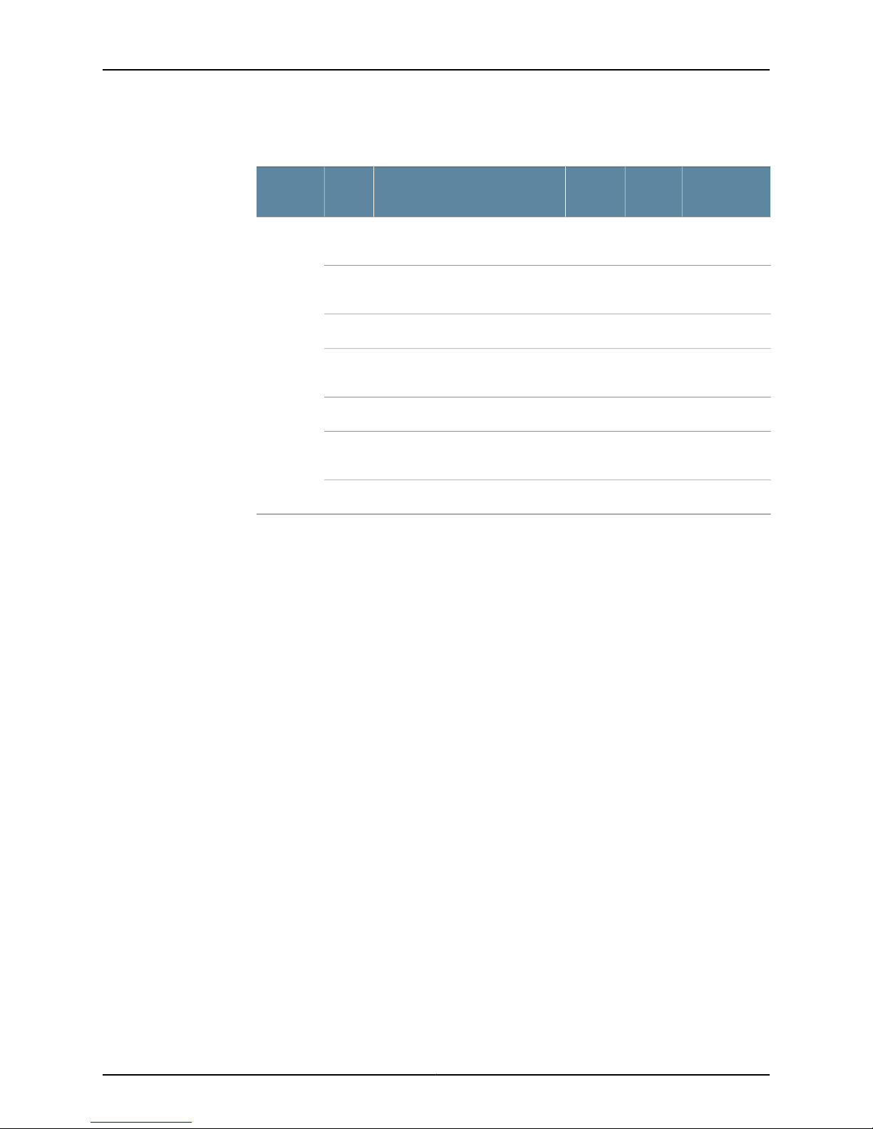
Table 1 on page 4 provides required port information on the NSMXpress Series II.
Table 1: Required Ports on NSMXpress Series II
NOTE: If you decide to install NSMXpress Series II in your DMZ, ensure that
it can connect to your internal resources.
443
8443
7800
7801
7802
7803
7804
Depends on
ConfigurationInternetLANDescriptionPortDirection
NoNoYesSSH command-line management22In
NoNoYesWeb interface for administrator
login
YesYesLANWebinterfacefor listening for NSM
API messages.
NoYesYesConnections from managed
devices to NSMXpress Series II
NoNoYesConnections from the NSM GUI
Client to NSM
YesNoYesHeartbeat between peers in an HA
cluster
YesYesYesConnections from managed IDP
devices to NSM
YesYesYesConnections from devices running
Junos , Secure Access devices, or
Infranet Controller devices
Copyright © 2010, Juniper Networks, Inc.4
Page 5
Hardware Installation
Table 1: Required Ports on NSMXpress Series II (continued)
Depends on
ConfigurationInternetLANDescriptionPortDirection
For more information on ports, refer to the Network and Security Manager Installation
Guide.
Installing the Hardware
Follow these steps to unpack the NSMXpress Series II appliance and connect it to your
network.
22Out
23
80
123
NoYesYesSSH connection to new managed
device
YesNoYesTelnet connection to new
managed device
NoNoYesDNS lookups53
YesYesNoSystem Security Updates from
Juniper Networks
YesNoYesShared Disk portmap lookup111
YesYesYesNetworkTime Protocol (NTP) time
synchronization
YesNoYesShared Disk NFS connection2049
To install NSMXpress Series II:
1. Place the shipping container on a flat surface and remove the hardware components
with care.
2. Remove the NSMXpress Series II device from the shipping container and place it on
a flat surface.
3. Mount NSMXpress Series II in your server rack using the attached mounting brackets.
4. Plug the power cord into the AC receptacle on the rear panel.
5Copyright © 2010, Juniper Networks, Inc.
Page 6
g040042
Power
supply
AC Power
supply
receptacle
AC Power Blank power
supply tray
switch
Fan 0 Fan 1
CONSOLE ETH1 ETH0
g040404
Power
LED
Hardware
LED
Hard disk LED
Left
LAN
LED
Right
LAN
LED
NSMXpress II
Hard disk
Activity LED
Hard disk
Failure LED
Network ports
Console
port
USB
maintenance
port
NSMXpress Quick Start
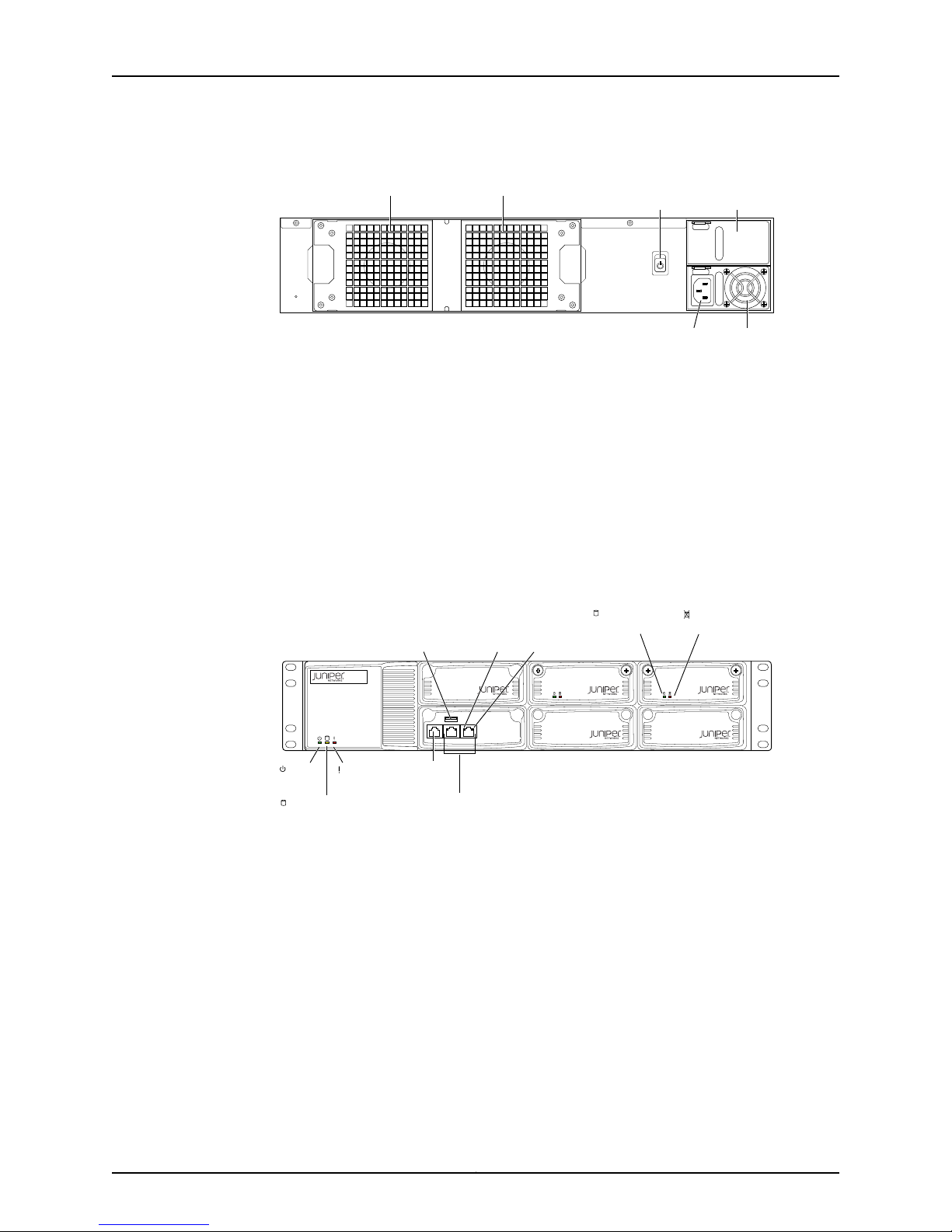
Figure 1: Rear Panel of NSMXpress Series II
If your NSMXpress Series II contains two power supplies, plug a power cord into each
AC receptacle.
5. Plug the other end of the power cord into a wall socket.
If your NSMXpress Series II contains two power supplies, plug each power cord into
a separate power circuit to ensure that the NSMXpress Series II continues to receive
power if one of the power circuits fails.
6. Plug the Ethernet cable into the network port marked ETH0 on the front panel. See
Figure 2 on page 6.
Figure 2: Front Panel of NSMXpress Series II
7. Plug the console cable with the DB9 to RJ45 adapter into the console port. See Figure
2 on page 6.
This cable was shipped with your NSMXpress Series II. See Table 3 on page 7
8. Push the power button on the rear panel. See Figure 1 on page 6
The green LED on the bottom left corner of the front panel turns on. The NSMXpress
Series II hard disk LED turns on wheneverthe appliance reads data from or writes data
to an NSMXpress Series II hard disk.
The internal port uses two LEDs to indicate the LAN connection status, which is
described in Table 2 on page 7.
Hardware installation is now complete. The next step is to set up the software, as
described in “Initial Setup Configuration” on page 7.
Copyright © 2010, Juniper Networks, Inc.6
Page 7

Initial Setup Configuration
Table 2 on page 7 provides LED information for the ETH0 and ETH1 ports.
Table 2: Ethernet Port LEDs
LED2LED 1LAN Status
OffOff10 Mbps connection
OffGreen100 Mbps connection
OffOrange1000 Mbps connection
BlinkingOrange, Green, or OffData is being transferred
OffOffNo connection
Table 3 on page 7 provides RJ-45 Console Connector Pinout information.
Table 3: RJ-45 Console Connector Pinout
Initial Setup Configuration
When you first turn on an unconfigured NSMXpress Series II appliance, you need to enter
basic network and machine information through the serial console to make your appliance
accessible to the network. After entering these settings, you can continue configuring
the appliance using the CLI or the Web interface. You are not prompted for the initial
setup information again.
DescriptionSignalPin
Request to SendRTS Output1
Data Terminal ReadyDTR Output2
Transmit DataTxD Output3
Chassis GroundGND4
Chassis GroundGND5
Receive DataRxD Input6
Data Set ReadyDSR Input7
Clear to SendCTS Input8
7Copyright © 2010, Juniper Networks, Inc.
Page 8

NSMXpress Quick Start
This section describes the required serial console setup and the tasks you need to perform
when connecting to your NSMXpress Series II for the first time:
•
Boot NSMXpress Series II on page 8
•
Set Up Your Appliance on page 8
Boot NSMXpress Series II
To configure NSMXpress Series II for the first time, you must attach your NSMXpress
Series II appliance to a console terminal running an emulation utility such as
HyperTerminal.
1. Configure a console terminal or terminal emulation utility to use the following serial
connection parameters:
•
9600 bits per second
•
8-bit no parity (8N1)
•
1 stop bit
Set Up Your Appliance
•
No flow control
2. Connect the terminal or laptop to the null modem serial cable plugged into the
NSMXpress Series II console port.
3. Turn on the NSMXpress Series II appliance.
When NSMXpress Series II is powered on, the serial console displays diagnostic
information before proceeding to the boot countdown. When complete, the serial
console displays the login prompt terminal emulator.
NSMXpress.juniper.net login:
4. Enter admin as your default login name.
5. Enter abc123 as your default password.
6. Change your default password when prompted. Enter the default password first,
followed by your new password. All passwords are case-sensitive.
This section provides the minimum informationnecessary to make your appliance active
on the network.
To set up your appliance either as a regional server or a central manager, follow these
steps:
1. Enter the IP address for interface eth0 and press Enter.
2. Enter the subnet mask for interface eth0 and press Enter.
3. Enter the default route or default gateway address for interface eth0 and press Enter.
Applying changes...
Re-loading database
ip_tables: (C) 2000–2002 Netfilter core team
Copyright © 2010, Juniper Networks, Inc.8
Page 9

Configuring the NSM Software
ip_tables: (C) 2000–2002 Netfilter core team
ip_tables: (C) 2000–2002 Netfileter core team
Done!
Your NSMXpress is now active on the network.
To configure your system via a web browser, connect to:
https://10.150.43.205/admin
To configure your system via command line, type:
nsm_setup
For operation of NSM server, switch to user “nsm”.
Please consult NSM product documentation for details.
[admin@NSMXpress ~]$
To configure the NSM software using the CLI, see the NSMXpress and NSM 3000 User
Guide. To configure the NSM software using the Web interface, go to “Web Interface
Configuration” on page 9.
Web Interface Configuration
To configure NSM on your system from a Web interface, use the following steps.
1. Copy the URL (starting with https://) from the terminal emulator after installing
NSMXpress:
Your NSMXpress is now active on the network.
To configure your system via a web browser, connect to:
https//10.150.43.205/administration
2. Open a Web browser and paste the URL into the address text box.
3. Press Enter to open the NSMXpress Series II login page.
4. Enter the admin user name and password and then click Login.
5. See “Configuring the NSM Software” on page 9 for details about how to install and
configure NSM on your NSMXpress Series II appliance from the Web interface.
Configuring the NSM Software
After logging in as an ‘admin’ user, an initial setup script walks you through additional
configurationsystemsettings before finalizing the NSM installation. This chapter describes
that setup process.
Your NSMXpress Series II appliance comes preconfigured as a regional server or a central
manager. Most installation and configuration steps in this section are identical for both
types of server. All exceptions are noted.
9Copyright © 2010, Juniper Networks, Inc.
Page 10

NSMXpress Quick Start
After logging into the NSMXpress Series II Web interface, NSMXpress Series II provides
you with the following installation options:
•
Configuring Basic Settings on page 10
•
Configuring High Availability on page 12
•
Advanced Options on page 15
•
Installing NSM Software on page 18
Configuring Basic Settings
To install the regional server or central manager software using the minimum
requirements:
1. Install your NSMXpress Series II hardware as described in “Hardware Installation” on
page 4.
2. Boot and setup your NSMXpress Series II appliance as described in “Initial Setup
Configuration” on page 7.
3. Enter the https://<ip>/administration URL for your appliance in a Web browser. See
“Web Interface Configuration” on page 9 for details.
4. Log into the Web interface. The System Info page opens.
5. Click the link Install NSM Regional Server (see Figure 3 on page 11) to go to the Install
Regional Server window or click the Install NSM Central Manager link to view the Install
NSM Central Manager window (see Figure 4 on page 11), as the case may be.
NOTE: The “admin” user default username is admin and the password is
the one you created in Step 6 of “Boot NSMXpress Series II” on page 8.
Copyright © 2010, Juniper Networks, Inc.10
Page 11
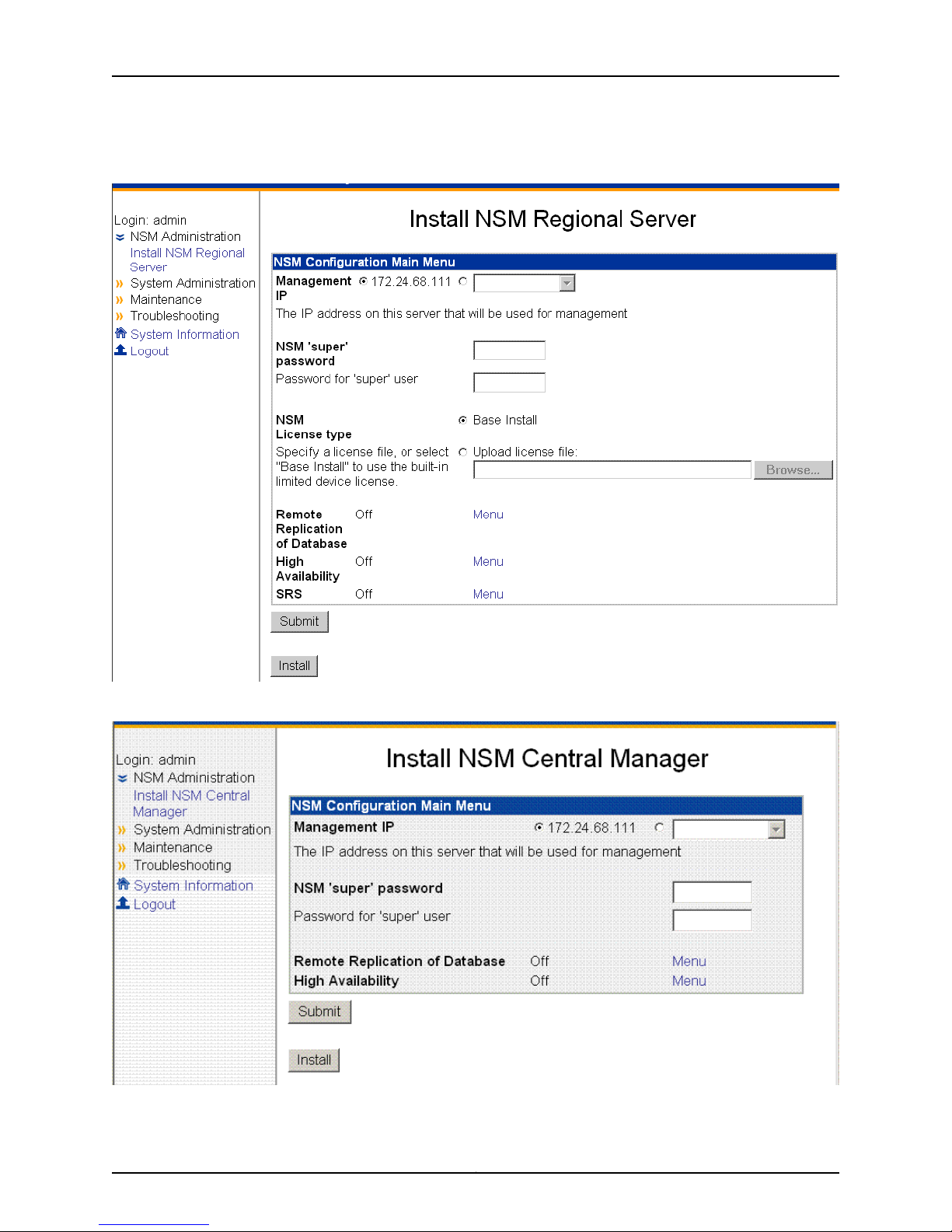
Figure 3: Regional Server Configuration Main Menu
Configuring the NSM Software
Figure 4: Central Manager Configuration Main Menu
11Copyright © 2010, Juniper Networks, Inc.
Page 12

NSMXpress Quick Start
6. Enter the primary IP address of your management server for eth0 (the default).
You can use the default IP address next to the first radio button or select the second
radio button and then enter a different IP address. Each IP address you add (in addition
to the default IP address) will be available in the drop-down list after you click the
second radio button.
7. Enter the NSM superuser password in the top text box, and then reenter it in the text
box below it.
This password must be at least eight characters long and is case-sensitive. This
password is used by the NSM superuser (also referred to as the NSM administrator).
This user has the highest level of privileges in NSM.
8. Enter the GUI Server one-time password in the top text box, and then reenter it in the
text box below it. This password is used to authenticate this NSM server with other
NSM servers with which it communicates. Regional servers use this password to
authenticate peer servers in an HA configuration and to authenticate the central
manager. The central manager uses this password to authenticate its peer server in
an HA configuration and any regional servers it manages. NSM servers must have the
same GUI Server one-time password, or the authentication will fail.
9. Select the license option. (This option is available only for regional servers.)
a. Select Base Install to use the built-in limited device license for as many as 25
devices.
b. Click Upload license file to upload the license file you generated using the Juniper
License Management System (LMS), which permits you to manage more than 25
devices. This license file must be located on your local hard drive.
See the Network and Security Manager installationGuide for more information about
NSM licensing.
10. Click Submit to save any changes, and then click Install to install the software.
Configuring High Availability
To configure high availability (HA) settings:
Copyright © 2010, Juniper Networks, Inc.12
Page 13
Configuring the NSM Software
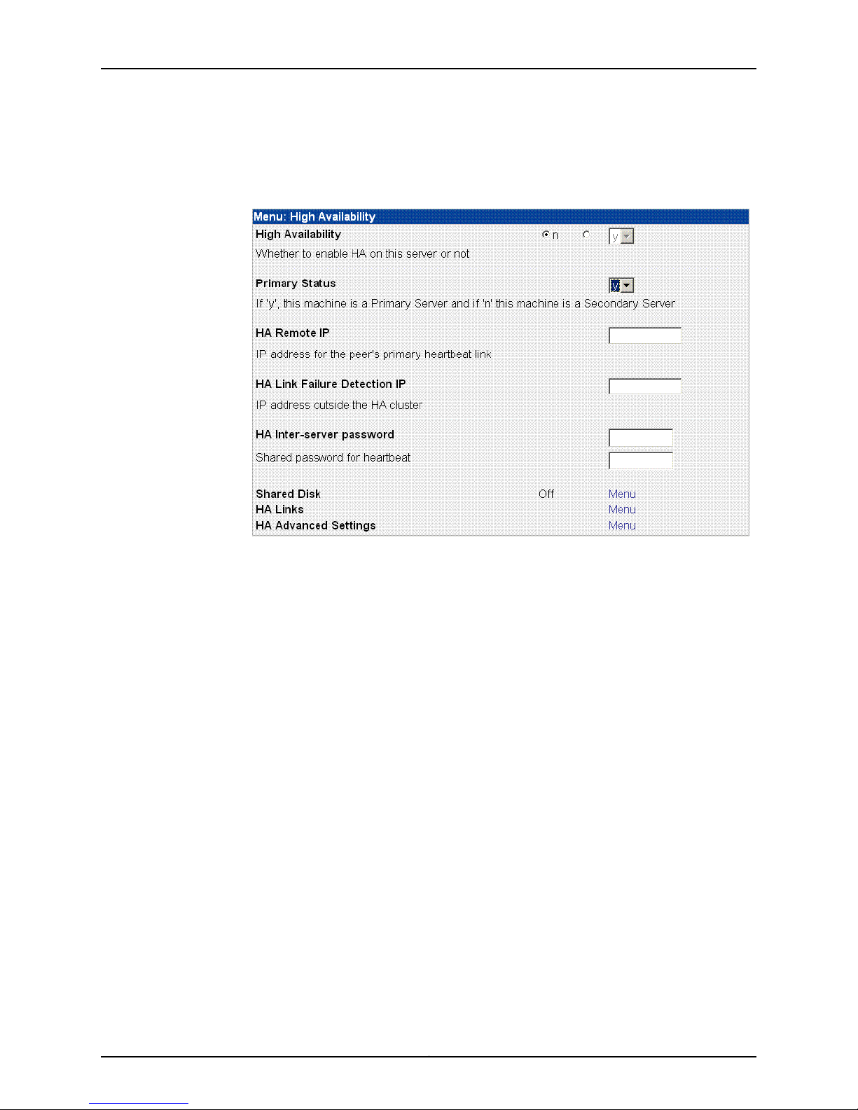
1. On the NSM Configuration Main Menu, click Menu next to High Availability to access
HA options. See Figure 5 on page 13.
Figure 5: High Availability Options
2. Use the High Availability option to turn HA on (y) or off (n). The default is off.
3. Use the Primary Status option to set your NSMXpress Series II appliance as either the
primary or secondary server in the HA cluster. If you select y, it is the primary server
(the default). If you select n, it is the secondary server.
4. Use the HA Remote IP option to enter the IP address for the HA peer in the HA cluster.
5. Use the HA Link Failure Detection IP option to enter the IP address of a computer
outside the HA cluster that you can ping to verify connection status.
6. Use the HA Inter-serverpasswordoption to enter the heartbeatpasswordused between
the primary and secondary servers.
7. Click Submit to save the changes.
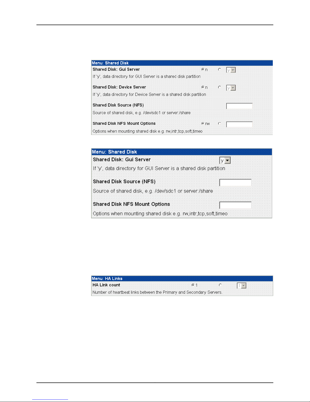
8. Click Menu next to Shared Disk (see Figure 5 on page 13) to configure a shared disk
for regional servers (see Figure 6 on page 14) or for central managers (see Figure 7
on page 14). This step is optional.
13Copyright © 2010, Juniper Networks, Inc.
Page 14
NSMXpress Quick Start
Figure 6: Shared Disk Options for Regional Servers
Figure 7: Shared Disk Options for Central Managers
NSMXpress Series II supports shared disk via NFS only. Due to the data-intensive
nature of NSM, we recommend gigabit speed links (1000 Mbps) for shared disk use.
For more information about custom settings, refer to the Network and Security Manager
Installation Guide.
9. Click Menu next to HA Links (see Figure 5 on page 13) to configure the second link in
the HA cluster (see Figure 8 on page 14). This step is optional.
Figure 8: HA Links Options
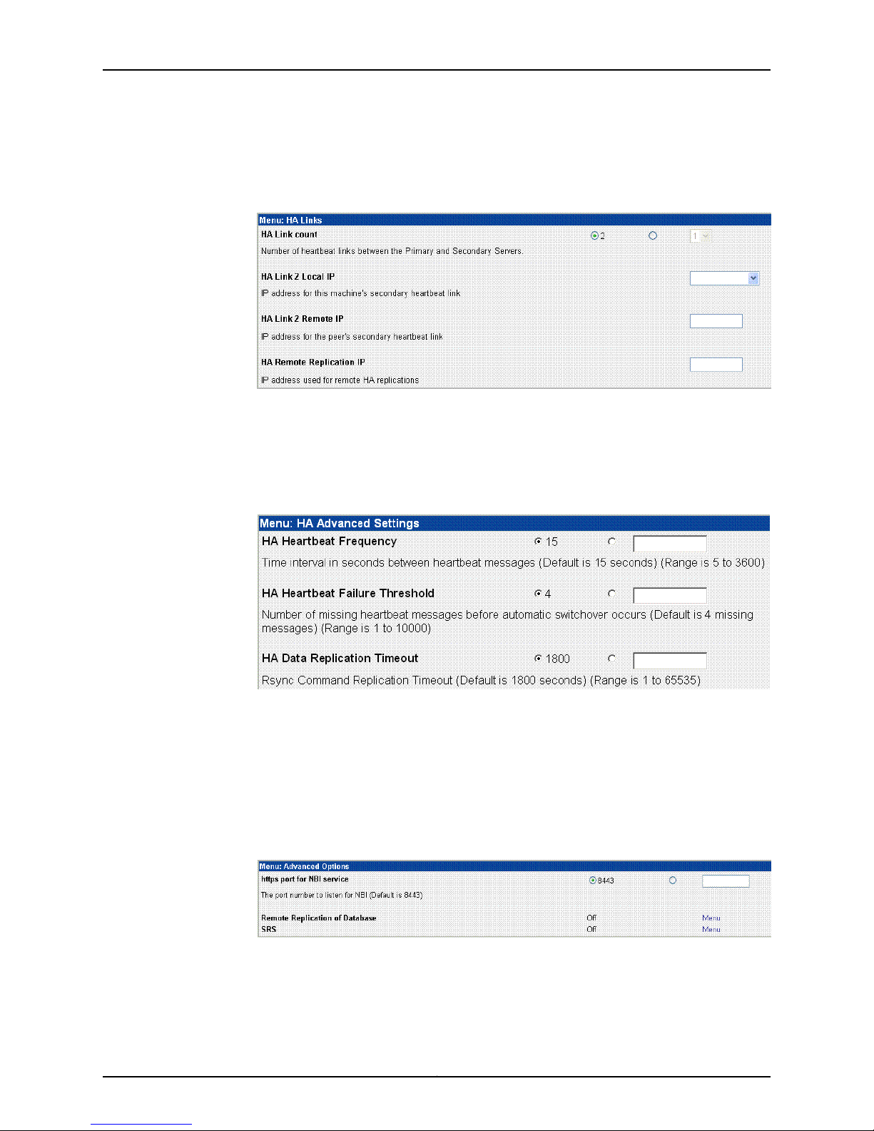
Use the options in this menu to set up a redundant link for the HA cluster. If you are
going to use a second link, you need to set the IP address for eth1 before configuring
this setting (see “Configuring the Network” on page 24 for details). Setting a redundant
link is optional. For more information about custom settings, refer to the Network and
Security Manager Installation Guide.
If you configure HA with just one heartbeat link, then device management traffic and
data replication traffic both use that link. If you configure two links, device management
traffic uses the first link and data replication uses the second.
Copyright © 2010, Juniper Networks, Inc.14
Page 15
Configuring the NSM Software
If you set the HA link count to 2, an expanded menu appears to configure the second
link:
Figure 9: Redundant Links
10. Click Menu next to HA Advanced Settings (see Figure 5 on page 13) to configure HA
advanced settings (see Figure 10 on page 15). This step is optional.
For more information about custom settings, refer to the Network and Security Manager
Installation Guide.
Advanced Options
Figure 10: HA Advanced Settings
11. Click Submit to save the HA options and return to the NSM Configuration Main Menu.
To display the Advanced Options menu, on the NSM Configuration Main Menu, select
Menu next to Advanced Options. The Advanced Options menu appears as shown in
Figure 11 on page 15.
Figure 11: Advanced Options Menu
Advanced installation options include:
15Copyright © 2010, Juniper Networks, Inc.
Page 16

NSMXpress Quick Start
•
https port for NBI service—Allows you to configure a port to listen for messages for the
NSM API. By default, this value is 8443. You can configure it to any port number from
1025 to 65535.
•
Remote Replication of Database—Mirrors the daily backup to an external server. You
can toggle it on or off. After you turn it on, use the menu options to configure this option.
•
SRS Enabled Options (regional server only)—Opens a menu to enable and configure
the Statistical Report Server (SRS). These options enable NSMXpress Series II to
interface with SRS. You can toggle it on or off. When it is on, a menu with additional
options is available.
NOTE: SRS must be installed on a separate server from NSM.
The following sections provide details about the remote replication and SRS options:
•
Enabling and Configuring Remote Replication of the Database on page 16
•
Enabling and Configuring SRS (Regional Server Only) on page 17
Enabling and Configuring Remote Replication of the Database
To configure remote replication of database settings:
1. On the Advanced Options menu, click Menu next to Remote Replication of Database
(see Figure 5 on page 13) to configure daily backups (see Figure 12 on page 16).
Figure 12: Remote Replication of Database Options
2. Use the Remote Replication of Database option to turn remote replication on (y) or
off (n). The default is off.
3. Use the Hour of day to Replicate Database option to start the backup. The valid range
(in hours) is 00 through 23. The default is 2 AM.
4. Use the Remote Backup IP option to enter the IP address of the remote backup server.
Backup information is copied to the /var/netscreen/dbbackup directory on the remote
server. The “nsm” user must exist on both servers and you must establish an SSH trust
relationship. See the Network and Security Manager Installation Guide, for details.
Copyright © 2010, Juniper Networks, Inc.16
Page 17
Configuring the NSM Software
5. Use the Remote Replication Timeout option to set up a timeout for Rsync. The valid
range (in seconds) is 1-65535. The default is 1800 seconds.
6. Click Submit to save the options and return to the main menu or continue with the
other advanced installation options.
Enabling and Configuring SRS (Regional Server Only)
This option is not available on a central manager. To configure statistical report server
(SRS) settings:
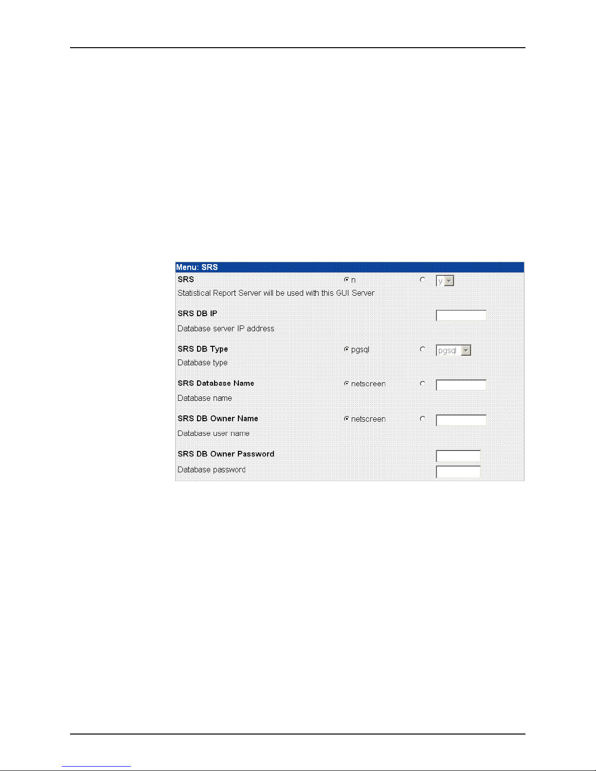
1. On the Advanced Options menu, click Menu next to SRS (see Figure 5 on page 13) to
open the SRS menu (see Figure 13 on page 17).
Figure 13: SRS Menu
2. Use the SRS options to turn SRS on (y) or off (n). The default is off. If you turn on this
feature, the server is used with the GUI server.
3. Use the SRS DB IP option to enter the IP address for the server on which you have
installed the SRS database server.
4. Use the SRS DB Type option to select the database type. The values are pgsql (the
default), oracle, or mssql.
5. Use the SRS Database Name option to enter the name of the SRS database. The
default value is netscreen. To enter another name, click the radio button next to the
blank text box and enter the name in the text box.
6. Use the SRS DB Owner Name option to enter the owner’s name of the SRS database.
The default value is netscreen. To enter another name, click the radio button next to
the blank text box and enter the name in the text box.
17Copyright © 2010, Juniper Networks, Inc.
Page 18

NSMXpress Quick Start
7. Use the SRS Database Owner Password option to enter the SRS database password.
The password requires a minimum of eight characters and is case-sensitive. Reenter
it in the second text box.
8. Click Submit to save the options and return to the NSM Configuration Main Menu.
Installing NSM Software
After you submit all your configuration options, click Install to install the NSM software
on your NSMXpress Series II appliance. Installation takes a few minutes. A status indicator
shows the progress of the installation. Wait until installation is finished before continuing
to use the Web interface.
Managing NSM Administration
Expand NSM Administration in the left navigation tree to access the options described
in this section. These options are available only after installing NSM.
The following sections explain how to use each of the NSM Administration options:
•
Changing the Superuser Password on page 18
•
Downloading NSM MIBS (Regional Server Only) on page 19
•
Exporting Audit Logs on page 19
•
Exporting Device Logs (Regional Server Only) on page 19
•
Generating Reports (Regional Server Only) on page 20
•
Modifying NSM Configuration Files on page 20
•
Backing Up the NSM Database on page 21
•
Changing the NSM Management IP on page 22
•
Scheduling Security Updates on page 22
Changing the Superuser Password
To change the superuser password, select NSM Administration > NSM Super User
Password. See Figure 14 on page 18.
Figure 14: Change Superuser Password
Copyright © 2010, Juniper Networks, Inc.18
Page 19

Downloading NSM MIBS (Regional Server Only)
To download any available MIBs, select NSM Administration > Download NSM MIBS,
and then click Download MIB. See Figure 15 on page 19. This option is not available on
the central manager.
Figure 15: Download NSM MIBs
Exporting Audit Logs
To export audit logs, select NSM Administration > Export Audit Logs. See Figure 16 on
page 19.
Figure 16: Export Audit Logs
Managing NSM Administration
To export an audit log to a csv file, select csv in the drop-down list box, and then enter
the csv file name in the text box.
To export an audit log to a system log server, select syslog in the drop-down list box,
and then enter the server IP address, if it is not the local host.
Exporting Device Logs (Regional Server Only)
To export device logs, select NSM Administration > Export Device Logs. See Figure 17
on page 19. This option is not available on the central manager.
Figure 17: Export Device Logs
19Copyright © 2010, Juniper Networks, Inc.
Page 20

NSMXpress Quick Start
Generating Reports (Regional Server Only)
To generate reports, select NSM Administration > Generate Reports. See Figure 18 on
page 20. This option is not available on the central manager.
Figure 18: Generate Reports
NOTE: The user is an NSM administrator and not an NSMXpress Series II
user. Enter a user name as domain/user, such as global/super.
Modifying NSM Configuration Files
To manually edit the GuiSrv.cfg, DevSvr.dfg and HaSvr.cfgfiles, select NSM Administration
> Modify NSM ConfigurationFiles. The example in Figure 19 on page 21, shows the option
to modify the GuiSvr.cfg file.
Copyright © 2010, Juniper Networks, Inc.20
Page 21

Figure 19: NSM Configuration Files
Managing NSM Administration
Backing Up the NSM Database
To configure backups of the NSM database,select NSM Administration> NSM Database
Backup link under NSM Administration. See Figure 20 on page 22.
NOTE: If you subsequently change the NSMXpress Series II configuration by
using the nsm-setup utility, all manual changes to the configuration files are
lost.
21Copyright © 2010, Juniper Networks, Inc.
Page 22

NSMXpress Quick Start
Figure 20: Database Backup
Changing the NSM Management IP
To change the IP address of the NSM management server, select NSM Administration
> NSM Management IP link under NSM Administration. See Figure 21 on page 22.
Figure 21: Change Management IP
Scheduling Security Updates
To schedule security updates, select NSM Administration > Schedule Security Updates.
See Figure 22 on page 23.
Copyright © 2010, Juniper Networks, Inc.22
Page 23

Figure 22: Schedule Security Updates
Managing System Administration
Managing System Administration
Use the options in the System Administration section to perform the tasks described in
the following sections:
•
Rebooting or Shutting Down NSMXpress Series II on page 23
•
Changing the User Password on page 24
•
Configuring the Network on page 24
•
Managing RADIUS Servers on page 26
•
Monitoring with SNMP on page 29
•
Forwarding Syslog Messages on page 32
•
Changing the System Time on page 35
•
Installing Updates on page 35
•
Managing Users on page 36
•
Configuring the Web Interface on page 40
Rebooting or Shutting Down NSMXpress Series II
To reboot or shut down NSMXpress Series II, select System Administration > Bootup
and Shutdown, and then click either Reboot System or Shutdown System. See Figure
23 on page 23.
Figure 23: ReBoot or Shut Down
23Copyright © 2010, Juniper Networks, Inc.
Page 24

NSMXpress Quick Start
Changing the User Password
To change the user password, select System Administration > Change User Password,
fill out the form shown in Figure 24 on page 24, and then click Change.
Figure 24: Change User Password
Configuring the Network
To access options that allow you to configure the network, select System Administration
> Network Configuration.The Network Configurationwindow appears as shown in Figure
25 on page 24.
Figure 25: Network Interfaces Options
The following sections describe each of the options available in the Network Configuration
window:
•
Network Interfaces on page 24
•
Routing and Gateways on page 25
•
Hostname and DNS Clients on page 25
•
Host Addresses on page 26
Network Interfaces
Use this option to manage the network interfaces. See Figure 26 on page 25.
Copyright © 2010, Juniper Networks, Inc.24
Page 25

Figure 26: Network Interfaces
Managing System Administration
Routing and Gateways
Use this option to configure and manage routes and gateways. See Figure 27 on page 25.
Figure 27: Routes and Gateways
Hostname and DNS Clients
Use this option to configure and manage hostnames and DNS clients. See Figure 28 on
page 26.
25Copyright © 2010, Juniper Networks, Inc.
Page 26

NSMXpress Quick Start
Figure 28: DNS Client Options
Host Addresses
Use this option to manage host addresses, See Figure 29 on page 26.
Figure 29: Host Address
Managing RADIUS Servers
The NSMXpress Series II WebUI supports authentication of users defined in the RADIUS
servers, in addition to authentication of locally defined admin users.
When a user logs into NSMXpress Series II using the WebUI, the software first checks the
UNIX user database and then the WebUI user database to authenticate the user. If the
user is not a locally defined admin user, the software contacts the RADIUS servers added
to the RADIUS server list in the Web UI to authenticate the user. The RADIUS servers are
contactedin the order of priority set in the RADIUS server list. If any of the RADIUS servers
authenticates the user, the user is logged in with the privileges that are associated with
the user profile. If none of the servers authenticates the user, the user login fails.
NOTE: The NSMXpress Series II appliance must be configured as a RADIUS
client on a RADIUS server so that the RADIUS server responds to
authentication requests from NSMXpress Series II. Select any Juniper Make
or Model in the Make/Model field while adding an NSMXpress appliance as
a RADIUS client. You will need to update the juniper dictionary file (juniper.dct)
in the RADIUS server with the Juniper defined Vendor-Specific Attribute (VSA)
for NSMXpress:ATTRIBUTE Juniper-Nsmxpress-Profile Juniper-VSA(6,
string) r . You will also need to add NSMXpress Series II users with their
associated user profiles (SysAdmin, NSMAdmin, Operator, Guest), to the
RADIUS database. For more details see Steel-Belted Radius Documentation.
Copyright © 2010, Juniper Networks, Inc.26
Page 27

Managing System Administration
NOTE: You need System Administration or NSM Administration permission
to manage RADIUS servers in the NSMXpress Series II WebUI.
•
Adding a RADIUS Server on page 27
•
Changing the Priority of RADIUS Servers on page 28
•
Deleting a RADIUS Server on page 28
•
Editing RADIUS Server Parameters on page 28
Adding a RADIUS Server
To add a RADIUS server:
1. Select System Administration > Radius Management. The RADIUS Servers dialog box
appears listing the RADIUS Servers that have been added. See Figure 30 on page 27.
Figure 30: RADIUS Servers Dialog Box
2. Click Add to add a RADIUS Server to the WebUI. The Add Radius Server dialog box
appears. See Figure 31 on page 27.
Figure 31: Add RADIUS Server Dialog Box
3. Configure the following parameters in the Add RADIUS Server dialog box:
a. Name: The name of the user to be authenticated by the RADIUS server.
b. Server address: The IP address or the hostname of the RADIUS Server.
c. Shared secret: The shared secret NSMXpress Series II and the RADIUS server use
for secure authentication.
27Copyright © 2010, Juniper Networks, Inc.
Page 28

NSMXpress Quick Start
d. Auth Port: The RADIUS authentication software port. (We recommend UDP port
1812.)
e. Acct Port: The RADIUS accounting software port. (We recommend UDP port 1813.)
f. Disconnect/CoA port: The change of authorization or disconnect port.
g. Timeout (sec): Automatic time out in second(s) of the RADIUS access-request
after which the request will be retransmitted, if applicable. Enter a value between
1 and 10 seconds.
h. Retries: The number of times the RADIUS access-request must be retransmitted
for RADIUS authentication. Enter a value between 1 and 5.
4. Click Add. The RADIUS Servers dialog box appears with the RADIUS Server you added
listed.
Changing the Priority of RADIUS Servers
To change the priority of RADIUS servers:
1. Select System Administration > Radius Management. The RADIUS Servers dialog box
appears listing the RADIUS Servers that have been added.
2. To increase the priority of a RADIUS server, select the check box next to the name of
the server whose priority you want to increase, and click Move Up.
To decrease the priority of a RADIUS server, select the check box next to the name of
the server whose priority you want to decrease, and click Move Down.
Deleting a RADIUS Server
To delete a RADIUS server:
1. Select System Administration > Radius Management. The RADIUS Servers dialog box
appears listing the RADIUS Servers that have been added.
2. Select the check box next to the name of the server you want to delete, and click
Delete Selected.
NOTE: You need System Administration permissions to delete RADIUS
servers.
Editing RADIUS Server Parameters
To edit the parameters of a RADIUS server:
1. Select System Administration > Radius Management. The RADIUS Servers dialog box
appears listing the RADIUS Servers that have been added.
2. Click the name of the server whose properties you want to edit. The Edit RADIUS
Server dialog box appears. See Figure 32 on page 29.
Copyright © 2010, Juniper Networks, Inc.28
Page 29

Monitoring with SNMP
Managing System Administration
Figure 32: Edit RADIUS Server Dialog Box
3. Edit the parameters you want to change and click Save.
You can configure your NSMXpress Series II appliance for SNMP monitoring from a
network operations server. The server can then issue periodic SNMP Get instructions to
return the status of the NSMXpress Series II appliance.
You configure SNMP on the NSMXpress Series II appliances with access credentials for
either SNMP v2c or SNMP v3. NSMXpress Series II supports read-only access to the
System Descriptor (sysDescr) and Host Resource MIB.
This section provides instructions for configuring NSMXpress Series II for SNMP monitoring.
You must provide access credentials for the SNMP server, a list of IP addresses from
which logon requests will be accepted, and the trap conditions to be reported to the
SNMP server.
To configure SNMP monitoring of your NSMXpress Series II appliance, select System
Administration > SNMP Monitoring. The SNMP window appears. This window contains
the tabs described in the following sections:
•
SNMP Configuration on page 29
•
SNMP System Information on page 30
•
SNMP Trap Configuration on page 31
SNMP Configuration
To configure SNMP:
1. Select System Administration > SNMP Monitoring.
2. Select the SNMP Config tab, which is shown in Figure 33 on page 30.
29Copyright © 2010, Juniper Networks, Inc.
Page 30

NSMXpress Quick Start
Figure 33: Configuring SNMP
3. Select the version of SNMP to be used, either v2c or v3.
4. Provide authentication information:
•
If you selected SNMP v2c, enter a username.
•
If you selected SNMP v3, enter a username and password.
The password must be at least 8 characters long.
NSMXpress Series II implements a single username and password, which is effective
only for SNMP communication and is not related to any other username and
password used on the NSMXpress Series II appliance.
5. To limit SNMP Get requests to specific servers, select Only, and then enter the IP
addresses of the permitted servers.
6. Click Save.
SNMP System Information
To configure SNMP system information:
1. Select System Administration > SNMP Monitoring.
2. Select the System Info tab, which is shown in Figure 34 on page 30.
Figure 34: Configuring SNMP System Information
3. Enter the following information, which is required for any SNMP-managed device:
•
Contact—Contact information for the appliance.
•
Location—Location of the appliance.
Copyright © 2010, Juniper Networks, Inc.30
Page 31

Managing System Administration
•
Description—A brief description of the appliance.
4. Click Save.
SNMP Trap Configuration
To configure SNMP trap conditions:
1. Select System Administration > SNMP Monitoring.
2. Select the SNMP Traps tab, which is shown in Figure 35 on page 31.
Figure 35: Configuring SNMP Traps
3. In the Manager IP field, enter the IP address of the SNMP management server.
4. Select from the following trap conditions:
•
Disk space low
Enter the percentage of free disk space below which SNMP issues a trap.
•
Memory low
Enter the percentage of free memory below which SNMP issues a trap.
•
CPU high
Enter the percentage of CPU use over which SNMP issues a trap.
•
NSM start/stop
•
Admin Logon/Logoff
•
External IP unreachable
Enter the IP address of the required device.
5. Click Save.
31Copyright © 2010, Juniper Networks, Inc.
Page 32

NSMXpress Quick Start
Forwarding Syslog Messages
NSMXpress Series II provides a simple mechanism for configuring syslog messaging
between the NSMXpress Series II appliance and a syslog receiver running rsyslog,
syslog-NG, or basic syslog. This mechanism simplifies choosing syslog receivers, data
sources of the messages you want to log, and the message transport used.
For the type of message transport, you can choose among TCP,SSL, and UDP. For rsyslog
or syslog-NG implementations use TCP or SSL. SSL adds security to TCP; if you select
SSL, NSMXpress Series II creates a secure tunnel to the syslog receiver. UDP messaging
is available for basic syslog implementations.
The following sections provide procedures for managing syslog message forwarding:
•
Viewing Syslog Receivers on page 32
•
Adding and Configuring Syslog Receivers on page 33
•
Editing Syslog Receiver Configurations on page 35
•
Deleting Syslog Receivers on page 35
Viewing Syslog Receivers
To view the syslog receivers configured on your NSMXpress Series II appliance, follow
these steps:
1. Select System Administration > Syslog Forwarding. The Syslog Forwarding window
appears. Figure 36 on page 34 shows an example.
Copyright © 2010, Juniper Networks, Inc.32
Page 33

Managing System Administration
2. View the configured syslog receivers in the table in the top portion of the window.
Table 4 on page 33 describes the fields.
Table 4: Viewing Syslog Receivers
DescriptionField
Receiver
A name provided by the network administratorto identify the syslog
receiver
The IP address of the syslog receiverIP Address
The protocol used for forwarding messages: UDP, TCP, SSLType
The data sources configured for forwardingData sources
The system logs configured to be sent to this receiver.System
The Device Server logs configured to be sent to this receiver.Device Server
The GUI Server logs configured to be sent to this receiver.GUI Server
The HA Server logs configured to be sent to this receiver.HA Server
Adding and Configuring Syslog Receivers
To add and configure a syslog receiver, follow these steps:
1. Select System Administration > Syslog Forwarding.
2. In the Data Sources section, select the syslog facility for each GUI Server log, Device
Server log, and HA Server log. The syslog facility is a field included in the syslog
message to help identify the data source.
3. Click Save.
4. Click Add new Receiver.
The syslog receiver configuration window appears as shown in Figure 36 on page 34.
33Copyright © 2010, Juniper Networks, Inc.
Page 34

NSMXpress Quick Start
Figure 36: Configuring a Syslog Receiver
5. In the Name field, enter a name for the syslog receiver. This is the name that the syslog
receiver will be known by within NSM.
6. In the IP field, Enter the IP address of the syslog receiver.
7. In the Transport field, select the type of syslog receiver:
•
Select UDP for basic syslog implementations.
•
Select TCP for rsyslog or syslog-NG implementations.
Copyright © 2010, Juniper Networks, Inc.34
Page 35

Managing System Administration
•
Select SSL to create a secure tunnel to a syslog receiver in rsyslog or syslog-NG
implementations.
•
In the System Logs section of the Data Sources table, select the sources of data
from which system messages will be forwardedto the syslog receiver. These sources
can include NSMXpress Series II system messages, package updates, and mail logs.
•
In the NSM section of the Data sources table, select each GUI Server log, Device
Server log, and HA Server log to be forwarded to the syslog receiver.
8. Click Save to save and apply the configuration.
Editing Syslog Receiver Configurations
To edit a syslog receiver configuration, follow these steps:
1. Select System Administration > Syslog Forwarding.
2. In the Syslog Receivers window, click the name of the syslog receiver you want to edit.
The syslog receiver configuration window appears for the selected receiver.
3. Make the desired changes to the configuration.
4. Click Save to save and apply your edits to the configuration of this syslog receiver.
Deleting Syslog Receivers
To delete a syslog receiver configuration, follow these steps:
1. Select System Administration > Syslog Forwarding.
2. In the Syslog Receivers window, check the box next to each syslog receiver you want
to delete.
3. Click Delete selected receivers.
NSMXpress Series II deletes the selected syslog receivers and any secure tunnels
configured for their use.
Changing the System Time
To set the system time, select System Administration > System Time. From the System
Time window, you can perform the following functions:
•
Set or change the system time.
•
Set the time zone.
•
Configure an NTP server to synchronize the system time with an external clock.
Installing Updates
Select System Administration > System Update to perform the following tasks:
•
Check for updates and install them.
•
Enable or disable automatic updates.
35Copyright © 2010, Juniper Networks, Inc.
Page 36

NSMXpress Quick Start
Managing Users
•
Install a new NSMXpress Series II version.
•
Add or modify proxy settings for the Yum server.
The NSMXpress Series II WebUI allows you to create multiple users with role-based
access control to the WebUI. You can create a user in the WebUI and associate the user
to a predefined user profile. You can also map a user created in the NSMXpress Series II
OS to a predefined user profile in the WebUI. However, this user profile is only applicable
to the local OS user in the WebUI.
NOTE: You need System Administration permission to create users.
This topic contains the following sections:
•
Creating New NSMXpress Series II Users on page 36
•
Deleting a User on page 38
•
Editing User Attributes on page 38
•
Understanding User Profiles on page 38
Creating New NSMXpress Series II Users
To create a local OS user:
1. Select System Administration > User Management. The NSMXpress Users dialog box
appears listing all NSMXpress users. See Figure 37 on page 36.
Figure 37: NSMXpress Users Dialog Box
2. Click Create a new NSMXpress User. The Create NSMXpress user dialog box appears.
See Figure 38 on page 37.
Copyright © 2010, Juniper Networks, Inc.36
Page 37

Managing System Administration
Figure 38: Create NSMXpress User Dialog Box
3. Enter the user name in the local OS, in the Username text box.
4. Select Unix authentication from the Password drop-down list. The Password and
Confirm Password text boxes will be disabled since the password will be fetched from
the local OS.
5. From the User Profile drop-down list box, select the user profile you want to associate
with the local user in the WebUI.
6. Click Submit. The NSMXpress Users dialog box appears with the new NSMXpress user
listed.
To create a WebUI user:
1. Select System Administration > User Management. The NSMXpress Users dialog box
appears listing all NSMXpress users. See Figure 39 on page 37.
Figure 39: NSMXpress Users Dialog Box
2. Click Create a new NSMXpress User. The Create NSMXpress user dialog box appears.
3. Enter a user name in the Username text box.
4. Select Set to from the password drop-down list and enter the password you want to
set in the password text box.
5. Reenter the password in the Confirm Password text box.
37Copyright © 2010, Juniper Networks, Inc.
Page 38

NSMXpress Quick Start
6. Select the user profile you want to associate with this user from the User Profile
drop-down list box.
7. Click Submit. The NSMXpress Users dialog box appears with the new NSMXpress user
listed.
Deleting a User
To delete a user:
1. Select System Administration > User Management. The NSMXpress Users dialog box
appears listing all NSMXpress users.
2. Select the check box next to the name of the user you want to delete and click Delete
Selected. Click Delete User in the Delete Users confirmation dialog box that appears.
NOTE: You cannot delete admin users or change their user profiles.
Editing User Attributes
To edit user attributes:
1. Select System Administration > User Management. The NSMXpress Series II Users
dialog box appears, with all NSMXpress Series II users listed.
2. Click on the name of the user whose attributes you want to edit. The Edit NSMXpress
Series II Users dialog box appears.
3. Edit the parameters you want to change and click Submit. You can change the
password and the user profile.
Understanding User Profiles
NSMXpress Series II I provides four predefined user profiles that allow you to implement
role-based access control over the NSMXpress Series II WebUI. A user created via the
WebUI or in the RADIUS server can be associated with any one of the following profiles:
•
System Administrator—System Administrators are superusers for the NSMXpress
Series II WebUI and have full access to all the modules in the NSMXpress Series II
WebUI.
•
NSM Administrator—NSM Administrators have access to NSM Administration, Radius
Management, Maintenance and Troubleshooting modules.
•
Network Operator—Network Operators have access to Network Utilities and Report
Generation Modules.
•
Guest User—Guest Users have read access to System Information and System Statistics
modules.
When a user logs in, NSMXpress Series II modules are displayed or hidden based on the
user profile and the permissions associated with the profile. For more details about user
profiles and permissions, see Table 5 on page 39.
Copyright © 2010, Juniper Networks, Inc.38
Page 39

Table 5: NSMXpress WebUI User Profiles and Permissions
Managing System Administration
System Administration
System
AdministratorNSMXpress Modules
NSM
Administrator
Network
Operator
Guest User
NoNoNoYesBootup and Shutdown
NoNoNoYesChange User Password
NoNoNoYesNetwork Configuration
NoNoYesYesRadius Management
NoNoNoYesSNMP Monitoring
NoNoNoYesSyslog Forwarding
NoNoNoYesSystem Time
NoNoNoYesSystem Update
NoNoNoYesUser Management
NoNoNoYesWebUI Configuration
NSM Administration
Maintenance
Troubleshooting
NoNoYesYesChange NSM Super User Password
NoNoYesYesDownload NSM MIBs
NoYesYesYesExport Audit Logs
NoYesYesYesExport Device Logs
NoYesYesYesGenerate Reports
NoNoYesYesNSM Configuration Files
NoNoYesYesNSM Database Backup
NoNoYesYesNSM Management IP
NoNoYesYesSchedule Security Updates
YesYesYesYesSystem Statistics
NoNoYesYesAction Audit Logs
39Copyright © 2010, Juniper Networks, Inc.
Page 40

NSMXpress Quick Start
Table 5: NSMXpress WebUI User Profiles and Permissions (continued)
Configuring the Web Interface
To specify which NSM client computers can access NSMXpress Series II through the Web
interface, select System Administration > WebUI Configuration. The Allowed IP
Addresses window appears as shown in Figure 40 on page 40.
Figure 40: Web Interface Access
System
AdministratorNSMXpress Modules
NSM
Administrator
Network
Operator
Guest User
NoYesYesYesError Logs
NoYesYesYesNetwork Utilities
NoYesYesYesTech Support
YesYesYesYesSystem Information
Maintaining NSMXpress Series II
The Maintaining section of the NSMXpress Series II navigation tree allows you to perform
the tasks described in the following sections:
•
Viewing System Statistics on page 40
•
Upgrading the Recovery Partition on page 42
Viewing System Statistics
To view system statistics, select System Administration > Maintenance > System
Statistics. The system Statistics window appears as shown in Figure 41 on page 41.
Copyright © 2010, Juniper Networks, Inc.40
Page 41

Maintaining NSMXpress Series II
Figure 41: System Statistics
CPU
Select CPU to view graphs that monitor the CPU activity hourly, daily, weekly, monthly,
or on a customizable basis.
Log Rate
Select lograte to view graphs that monitor the log rate hourly, daily, weekly, monthly, or
on a customizable basis.
CPU Load
Select Load to view graphs that monitor the CPU load hourly, daily, weekly, monthly, or
on a customizable basis.
Memory Data
Select Memory to view graphs that monitor the memory activity hourly, daily, weekly,
and monthly.
Network Data
Select either eth0 or eth1 to view graphs that monitor network activity hourly, daily,
weekly, and monthly.
Process Count
SelectProcess to view graphs that monitor the number of processes hourly,daily, weekly,
and monthly.
Disk Data
Select Disk to view graphs that monitor the file system disk space usage hourly, daily,
weekly, and monthly.
Tile All Graphs
Select Tile all graphs to display all the statistical graphs for the system in one window.
41Copyright © 2010, Juniper Networks, Inc.
Page 42

NSMXpress Quick Start
Upgrading the Recovery Partition
The recovery partition contains all files necessary to perform a clean installation of the
NSMXpress Series II OS and its applications with default settings. It provides a last-resort
recovery mechanism. When the NSMXpress Series II appliance is shipped from the factory,
the recovery partition files match the version of the NSMXpress Series II OS with factory
default settings.
Using the Recovery Upgrade option, you can make the current version of NSMXpress
Series II available for recovery, displacing the existing files in the recovery partition. The
factorydefaultrecovery files are retainedas an alternativerecoverychoice. Other versions
are deleted.
Recovery upgrade uses two sets of packages to create a set of files from which you can
perform a clean installation. One set makes up the NSMXpress Series II OS, the other a
set of upgrade script packages. Both sets are usually retained in the local file system.
The NSMXpress Series II OS set can also be downloaded form the Juniper Networks
software repository.
NSMXpress Series II splits the recovery upgrade process into a preparation phase and
an upgrade phase. In the preparation phase, NSMXpress Series II assembles a copy of
the current version of the image files in temporary workspace. In the upgrade phase,
NSMXpress Series II replaces the old recovery image files, and installs the current version
of the image files from the temporary workspace into the recovery partition. By splitting
the process into two phases, NSMXpress Series II minimizes the period of vulnerability
while the upgrade itself takes place.
To upgrade the recovery partition, follow these steps:
1. Select System Administration > Maintenance > Update Recovery Partition.
If the new recovery partition files have already been prepared, then the Upgrade screen
appears. Proceed with the upgrade phase as described in step 5.
If the upgrade files have not yet been prepared, the Upgrade Preparation window
appears. Proceed with the preparation phase in step 2.
2. Enter the location of the NSMXpress Series II Regional server or Central Manager
upgrade zip file, downloaded from the Juniper Customer Support Center when
upgrading NSM, on the local file system.
3. If the NSMXpress Series II Offline server upgrade file is available on the local file
system, enter the location and name of the NSMXpress Series II offline server upgrade
file in the System upgrade source field. If the NSMXpress Series II offline server upgrade
file is not available on the local file system and the appliance has access to the Juniper
Update site, select Online.
4. Click Prepare System.
The Preparation Progress screen shows the progress of the operation.
Errors are reported if the required files are unavailable, disk space is not sufficient, or
the previous version files are invalid.
Copyright © 2010, Juniper Networks, Inc.42
Page 43

Troubleshooting
Troubleshooting
When preparation is completed, the Upgrade window appears.
5. In the Upgrade window, enter the admin Web UI password and then click Start Update.
The upgrade process usually takes less than one minute.
CAUTION: Do not interrupt the upgrade process. If you do, your NSMXpress
Series II appliance might not boot normally.
Use the options in the Troubleshooting section to access the following information and
utilities:
•
Auditing User Operations on page 43
•
Error Logs on page 44
•
Network Utilities on page 45
•
Tech Support on page 48
Auditing User Operations
You can audit all user operations performed in NSMXpress Series II. Users with System
Administrator and NSM administrator permissions can view all Actions Logs in NSMXpress
Series II.
To view Action Audit Logs:
1. Select Troubleshooting > Action Audit Logs. The NSMXpress Actions Log dialog box
Figure 42: NSMXpress Actions Dialog Box
appears. See Figure 42 on page 43.
2. Select the Action Audit Logs that you want to view:
43Copyright © 2010, Juniper Networks, Inc.
Page 44

NSMXpress Quick Start
•
Actions by NSMXpress Users: Select the By any user check box to select actions by
all users. Select the By user check box and choose a username from the drop-down
list to specify actions by a particular user. Select By any user except and choose a
username from the drop-down list to exclude actions by a specific user.
•
Actions by User Profile: Select the By any profile check box to select actions by all
user profiles. Selectthe By profile check box and choose a profile from the drop-down
list to specify actions by a specific user profile. Select By any profile except and
choose a profile from the drop-down list to exclude actions by a user profile.
•
Actions by authentication mechanism: Select the By any authentication check box
to select actions by all authentication mechanisms. Select the By authentication
check box and choose an authentication mechanism from the drop-down list to
specify actions by a specific authentication mechanism. SelectBy any authentication
except and choose a profile from the drop-down list to exclude actions by an
authentication mechanism.
•
Actionsin module: Select the In any module check box to select actions in all modules.
Select the In module check box and choose a module from the drop-down list to
specify actions in a particular module.
•
Actions on dates: Select the At any time check box to select actions at any time.
Selectthe For today only check box to select today’s actions. Select the For yesterday
only check box to select yesterday’s actions. Select the During the last week check
box to select last week’s actions. Select the Between check box and enter the start
date and end date in the drop-down list to view actions within the specified time
period.
3. Click Search. The Search Results dialog box appears with the result of your query. See
Figure 43 on page 44.
Figure 43: Search Results Dialog Box
Error Logs
To review error logs, select Troubleshooting > Error Logs. Figure 44 on page 45 shows
an example,
Copyright © 2010, Juniper Networks, Inc.44
Page 45

Troubleshooting
Figure 44: Review Error Logs
To view details of an individual error log, select the file you want to view and click View.
Figure 45 on page 45 shows sample error log details.
Figure 45: Error Log Detail
Network Utilities
To access basic network utilities (ping, traceroute, and nslookup) for TCP/IP Networking,
select Troubleshooting > Network Utilities. These tools also provide an IP subnet
calculator. SeeFigure 46 on page 45.
Figure 46: Network Utilities Options
Ping
Ping is a tool for checking network connectivity. NSMXpress prompts with questions so
you can focus your search.
Figure 47 on page 46 shows an example.
45Copyright © 2010, Juniper Networks, Inc.
Page 46

NSMXpress Quick Start
Figure 47: Ping Utility
How Many Packets
Enter the number of packets this ping command will send. The default is 5. The values
range from 1 through 99.
Packet Size
Enter the packet size (in bytes) this ping command will send. The default is 56. The values
range from 1 through 9999.
How Many Sec Between Sending Each Packet
Enter how much time (in seconds) ping should wait between sending each packet.
Patterns to Send (Hex)
The data sent by ping contains a hexadecimal pattern. If you leave this option blank, ping
will fill it with random data. This option is useful if you do not have problems with
connectivity itself but with data loss.
Verbosity Output
NSMXpress lists the ICMP packets(other than ECHO_Response) that have been received.
Numeric Output Only
Check this option if you do not want any attemptsto be made to look up symbolic names
for host addresses.
Bypass Routing Tables
If the host is not a directly attached network, an error is returned. This option can be used
to ping a local host through an interface that has no route through it.
Traceroute
Traceroute is a tool to print the route a packet takes to a network host. See Figure 48 on
page 47.
Copyright © 2010, Juniper Networks, Inc.46
Page 47

Figure 48: Traceroute Utility
NOTE: The only required field is Hostname. The value can be either a
hostname or an IP address.
Troubleshooting
Lookup
Use the lookup tool to obtain the IP address from a hostname and the hostname from
an IP address (see Figure 49 on page47). The query type drop-down list contains several
types of records found in the DNS database. Enter a nameserver or select the default. If
you choose the default, nslookup will use the server on which NSMXpress is installed.
Figure 49: Lookup Utility
IP Subnet Calculator
Use the IP subnet calculator to calculate the netmask for a TCP/IP-network. You can
calculate a netmask by class and subnet bits or by the number of hosts (See Figure 50
on page 48) When you calculate a netmask by the number of hosts, NSMXpress returns
the smallest network available.
47Copyright © 2010, Juniper Networks, Inc.
Page 48

NSMXpress Quick Start
Tech Support
Figure 50: IP Subnet Calculator
To get contact information for Juniper Networks technical support, select Troubleshooting
> Tech Support. To help analyze problems, select a detail type in the drop-down list box,
and then click Run Tech-Support Script. NSMXpress creates a file you can download
and send to Juniper Networks technical support. See Figure 51 on page 48.
Figure 51: Juniper Tech Support
Viewing System Information
Use the SystemInformation menu item to display information about the server, including
CPU load and memory use, as shown in Figure 52 on page 49.
Copyright © 2010, Juniper Networks, Inc.48
Page 49

Figure 52: System Information
Rack-Mounting the NSMXpress Series II Appliance
Rack-Mounting the NSMXpress Series II Appliance
This section provides the types and procedures for mounting the NSMXpress Series II
appliances on the Juniper UNIMOUNT rack-mount systems.
The NSMXpress Series II appliance supports the following rack types:
•
19” 4-post rack
•
19" 2-post rack
The rack-mount system is flexible and offers several options for rack-mounting the
hardware. The different options include:
•
Front-Mounting Flush to Rack on page 49
•
Front-Mounting Recessed in Rack on page 50
•
Front-Rear-Mounting Flush to Rack on page 51
•
Front-Rear- Mounting Recessed in Rack on page 51
•
Mid-Mount in Two Post Equipment Rack on page 52
Front-Mounting Flush to Rack
NOTE: If you are installing multiple NSMXpress Series II appliances in one
rack, you should install the lowest one first and proceed upward in the rack.
Install heavier NSMXpress Series II appliances in the lower part of the rack.
To mount the appliance using this option:
1. Attach the chassis to the equipment rack using 4 rack-mount screws on each side of
the system. See Figure 53 on page 50.
49Copyright © 2010, Juniper Networks, Inc.
Page 50

NSMXpress Quick Start
2. Verify that the mounting screws on one side of the rack are aligned with the mounting
screws on the opposite side and that the appliance is level.
Figure 53: Front-Mounting flush to rack
Front-Mounting Recessed in Rack
This option allows sites with no front-of-rack clearance to recess the NSMXpress Series
II system in the equipment rack.
To mount the appliance using this option:
1. Remove the rear screws on each side of the system’s front rails and the two small
screws towards the front of the chassis.
2. Loosen the side rail screws of the chassis and slide the front rails of the system forward,
as far as they will move. See Figure 54 on page 50.
3. Tighten the side rail screws. Insert the two small screws in the recessed holes on the
front rails and tighten.
4. Insert 4 rack-mount screws on each side of the system to secure the chassis to the
rack-mount system.
5. Verify that the mounting screws on one side of the rack are aligned with the mounting
screws on the opposite side and that the appliance is level.
Figure 54: Front-Mounting recessed in rack
Copyright © 2010, Juniper Networks, Inc.50
Page 51

The recessed position allows network and console cables to be routed through the sides
of the equipment rack and through the holes of the recessed front rails on either side of
the unit. This enables easy cable routing on the racks with limited cable management.
Front-Rear-Mounting Flush to Rack
This option is used for larger chassis that require additional support when mounted on
the rack-mount system.
To mount NSMXpress Series II using this option:
1. Insert 4 rack-mount screws on each side of the system to secure the front of the
chassis to the equipment rack.
2. Slide the rear mount rail brackets into the backs of the front rails on either side of the
chassis and align with your rear equipment rack posts. Secure the rear mount rail
brackets to your equipment rack with 2 rack mount screws each.
3. Insert locking screws on the sides of the rear mount brackets to secure the front and
rear mounting brackets in place. See Figure 55 on page 51.
Front-Rear-Mounting Flush to Rack
4. Verify that the mounting screws on one side of the rack are aligned with the mounting
screws on the opposite side and that the appliance is level.
Figure 55: Front-Rear-Mounting flush to rack
Front-Rear- Mounting Recessed in Rack
This option provides additional front clearance in the equipment rack. It is used for larger
chassis, that requires additional support when mounted on the rack-mount system.
To mount the appliance using this option:
1. Remove the rear screws on each side of the system’s front rails and the two small
screws towards the front of the chassis.
2. Remove the rear screws on each side of the system’s front rails and the two small
screws towards the front of the chassis.
3. Tighten the side rail screws. Insert the two small screws in the recessed holes on the
front rails and tighten.
51Copyright © 2010, Juniper Networks, Inc.
Page 52

NSMXpress Quick Start
4. Slide the rear mount rail brackets into the backs of the front rails on either side of the
chassis and align with your rear equipment rack posts. Secure the rear mount rail
brackets to your equipment rack with 2 rack mount screws each. See Figure 56 on
page 52.
5. Insert locking screws on the sides of the rear mount brackets to secure the front and
rear mounting brackets in place.
6. Verify that the mounting screws on one side of the rack are aligned with the mounting
screws on the opposite side and that the appliance is level.
Figure 56: Front-Rear-Mounting recessed in rack
The recessed position allows network and console cables to be routed through the sides
of the equipment rack and throught the holes of the recessed front rails on either side of
the unit. This enables easy cable routing on the racks with limited cable management.
Mid-Mount in Two Post Equipment Rack
This option is suitable for a two post equipment rack. It allows the appliance to be
mid-mounted so that there is even clearance on the front and rear of the rack.
To mount the appliance using this option:
1. Remove the two front mount rails from either side of the chassis.
2. Insert one mid-mount bracket to the center on either side of the chassis.
3. Attach the chassis to the equipment rack and insert the other two mid-mount brackets
on either side of the system to secure the chassis to the backs of the post. See Figure
57 on page 53.
4. Verify that the mounting screws on one side of the rack are aligned with the mounting
screws on the opposite side and that the appliance is level.
Copyright © 2010, Juniper Networks, Inc.52
Page 53

Figure 57: Mid-Mount in two post equipment rack
List of Technical Publications
List of Technical Publications
Table 6 on page 53 describes the documentation for NSMXpress and NSM.
Table 6: Network and Security Manager Publications
DescriptionBook
Network and Security
Manager Installation Guide
Network and Security
Manager Administration
Guide
Network and Security
Manager Configuring
ScreenOS and IDP Devices
Guide
Describes the steps to install the NSM management system on a
single server or on separate servers. It also includes information on
how to install and run the NSM user interface. This guide is intended
for IT administrators responsible for the installation or upgrade of
NSM.
Describes how to use and configure key management features in
the NSM. It provides conceptual information, suggested workflows,
and examples. This guide is best used in conjunction with the NSM
Online Help, which provides step-by-step instructions for performing
management tasks in the NSM user interface (UI).
This guide is intended for application administrators or those
individuals responsible for owning the server and security
infrastructure and configuring the product for multiuser systems. It
is also intended for device configuration administrators, firewall
and VPN administrators, and network security operation center
administrators.
Describes NSM features related to device configuration and
management. It also explains how to configure basic and advanced
NSM functionality, including deploying new device configurations,
managing security policies and VPNs, and general device
administration.
53Copyright © 2010, Juniper Networks, Inc.
Page 54

NSMXpress Quick Start
Table 6: Network and Security Manager Publications (continued)
DescriptionBook
Network and Security
Manager Online Help
Network and Security
Manager API Guide
Network and Security
Manager Release Notes
NSMXpress and NSM3000
User Guide
NSMXpress Series II User
Guide
Network and Security
Manager Configuring
Infranet Controllers Guide
Network and Security
Manager Configuring Secure
Access Devices Guide
Provides procedures for basic tasks in the NSM user interface. It
also includes a brief overview of the NSM system and a description
of the GUI elements.
Provides complete syntax and a description of the Simple Object
Access Protocol (SOAP) messaging interface to NSM.
Provides the latest information about features, changes, known
problems, resolved problems, and system maximum values. If the
information in the Release Notes differs from the information found
in the documentation set, follow the Release Notes.
Release Notes are included on the corresponding software CD and
are available on the Juniper Networks Website.
Describes how to set up and manage the NSM appliances as a
central manager or regional server.
Describes how to set up and manage the NSMXpress Series II
appliance as a central manager or regional server.
Provides details about configuring the device features for all
supported Infranet Controllers.
Provides details about configuring the device features for all
supported Secure Access Devices.
Network and Security
Manager Configuring EX
Series Switches Guide
Network and Security
Manager Configuring J
Series Services Routers and
SRX Series Services
Gateways Guide
Network and Security
Manager M Series and MX
Series Devices Guide
Requesting Technical Support
Technical product support is available through the Juniper Networks Technical Assistance
Center (JTAC). If you are a customer with an active J-Care or JNASC support contract,
or are covered under warranty, and need post-sales technical support, you can access
our tools and resources online or open a case with JTAC.
Provides details about configuring the device features for all
supported EX Series platforms.
Provides details about configuring the device features for all
supported J Series Services Routers and SRX Series Services
Gateways.
Provides details about configuring the device features for M Series
and MX Series platforms.
Copyright © 2010, Juniper Networks, Inc.54
Page 55

•
JTAC policies—For a complete understanding of our JTAC procedures and policies,
review the JTAC User Guide located at
http://www.juniper.net/us/en/local/pdf/resource-guides/7100059-en.pdf .
•
Product warranties—For product warranty information, visit
http://www.juniper.net/support/warranty/ .
•
JTAC hours of operation—The JTAC centers have resources available 24 hours a day,
7 days a week, 365 days a year.
Self-Help Online Tools and Resources
For quick and easy problem resolution, Juniper Networks has designed an online
self-service portal called the Customer Support Center (CSC) that provides you with the
following features:
•
Find CSC offerings: http://www.juniper.net/customers/support/
•
Search for known bugs: http://www2.juniper.net/kb/
•
Find product documentation: http://www.juniper.net/techpubs/
Requesting Technical Support
•
Find solutions and answer questions using our Knowledge Base: http://kb.juniper.net/
•
Download the latest versions of software and review release notes:
http://www.juniper.net/customers/csc/software/
•
Search technical bulletins for relevant hardware and software notifications:
https://www.juniper.net/alerts/
•
Join and participate in the Juniper Networks Community Forum:
http://www.juniper.net/company/communities/
•
Open a case online in the CSC Case Management tool: http://www.juniper.net/cm/
To verify service entitlement by product serial number, use our Serial Number Entitlement
(SNE) Tool: https://tools.juniper.net/SerialNumberEntitlementSearch/
Opening a Case with JTAC
You can open a case with JTAC on the Web or by telephone.
•
Use the Case Management tool in the CSC at http://www.juniper.net/cm/ .
•
Call 1-888-314-JTAC (1-888-314-5822 toll-free in the USA, Canada, and Mexico).
For international or direct-dial options in countries without toll-free numbers, see
http://www.juniper.net/support/requesting-support.html .
55Copyright © 2010, Juniper Networks, Inc.
Page 56

NSMXpress Quick Start
Revision History
November 17, 2010— Revision 1.
Copyright © 2010, Juniper Networks, Inc. All rights reserved.
Juniper Networks, Junos, Steel-Belted Radius, NetScreen, and ScreenOS are registered trademarks of Juniper Networks, Inc. in the United
States and other countries. The Juniper Networks Logo, the Junos logo, and JunosE are trademarks of Juniper Networks, Inc. All other
trademarks, service marks, registered trademarks, or registered service marks are the property of their respective owners.
Juniper Networks assumes no responsibility for any inaccuracies in this document. Juniper Networks reserves the right to change, modify,
transfer, or otherwise revise this publication without notice.
Products made or sold by Juniper Networks or components thereof might be covered by one or more of the following patents that are
owned by or licensed to Juniper Networks: U.S. Patent Nos. 5,473,599, 5,905,725, 5,909,440, 6,192,051, 6,333,650, 6,359,479, 6,406,312,
6,429,706, 6,459,579, 6,493,347, 6,538,518, 6,538,899, 6,552,918, 6,567,902, 6,578,186, and 6,590,785.
Copyright © 2010, Juniper Networks, Inc.56
 Loading...