

Juniper NETWORK AND SECURITY MANAGER - NSM CONFIGURATION GUIDE FOR EX SERIES DEVICES REV 3, NETWORK AND SECURITY MANAGER Configuration Manual
Page 1

NSM Configuration Guide for EX Series Devices
Release
Published: 2010-11-15
Part Number: 530-028689-01, Revision 3
Copyright © 2010, Juniper Networks, Inc.
Page 2

Juniper Networks, Inc.
1194 North Mathilda Avenue
Sunnyvale, California 94089
USA
408-745-2000
www.juniper.net
This product includes the Envoy SNMP Engine,developed by Epilogue Technology, an IntegratedSystemsCompany.Copyright © 1986-1997,
Epilogue Technology Corporation. All rights reserved. This program and its documentation were developed at private expense, and no part
of them is in the public domain.
This product includes memory allocation software developed by Mark Moraes, copyright © 1988, 1989, 1993, University of Toronto.
This product includes FreeBSD software developed by the University of California, Berkeley, and its contributors. All of the documentation
and software included in the 4.4BSD and 4.4BSD-Lite Releases is copyrighted by the Regents of the University of California. Copyright ©
1979, 1980, 1983, 1986, 1988, 1989, 1991, 1992, 1993, 1994. The Regents of the University of California. All rights reserved.
GateD software copyright © 1995, the Regents of the University. All rights reserved. Gate Daemon was originated and developed through
release 3.0 by Cornell University and its collaborators. Gated is based on Kirton’s EGP, UC Berkeley’s routing daemon (routed), and DCN’s
HELLO routing protocol. Development of Gated has been supported in part by the National Science Foundation. Portions of the GateD
software copyright © 1988, Regents of the University of California. All rights reserved. Portions of the GateD software copyright © 1991, D.
L. S. Associates.
This product includes software developed by Maker Communications, Inc., copyright © 1996, 1997, Maker Communications, Inc.
Juniper Networks, Junos, Steel-Belted Radius, NetScreen, and ScreenOS are registered trademarks of Juniper Networks, Inc. in the United
States and other countries. The Juniper Networks Logo, the Junos logo, and JunosE are trademarks of Juniper Networks, Inc. All other
trademarks, service marks, registered trademarks, or registered service marks are the property of their respective owners.
Juniper Networks assumes no responsibility for any inaccuracies in this document. Juniper Networks reserves the right to change, modify,
transfer, or otherwise revise this publication without notice.
Products made or sold by Juniper Networks or components thereof might be covered by one or more of the following patents that are
owned by or licensed to Juniper Networks: U.S. Patent Nos. 5,473,599, 5,905,725, 5,909,440, 6,192,051, 6,333,650, 6,359,479, 6,406,312,
6,429,706, 6,459,579, 6,493,347, 6,538,518, 6,538,899, 6,552,918, 6,567,902, 6,578,186, and 6,590,785.
Network and Security Manager Administration Guide
Copyright © 2010, Juniper Networks, Inc.
All rights reserved. Printed in USA.
Revision History
November 17, 2010— Revision 3
The information in this document is current as of the date listed in the revision history.
Copyright © 2010, Juniper Networks, Inc.ii
Page 3

END USER LICENSE AGREEMENT
READ THIS END USER LICENSE AGREEMENT (“AGREEMENT”) BEFORE DOWNLOADING, INSTALLING, OR USING THE SOFTWARE.
BY DOWNLOADING, INSTALLING, OR USING THE SOFTWARE OR OTHERWISE EXPRESSING YOUR AGREEMENT TO THE TERMS
CONTAINED HEREIN, YOU (AS CUSTOMER OR IF YOU ARE NOT THE CUSTOMER, AS A REPRESENTATIVE/AGENT AUTHORIZED TO
BIND THE CUSTOMER) CONSENT TO BE BOUND BY THIS AGREEMENT. IF YOU DO NOT OR CANNOT AGREE TO THE TERMS CONTAINED
HEREIN, THEN (A) DO NOT DOWNLOAD, INSTALL, OR USE THE SOFTWARE, AND (B) YOU MAY CONTACT JUNIPER NETWORKS
REGARDING LICENSE TERMS.
1. The Parties. The parties to this Agreement are (i) Juniper Networks, Inc. (if the Customer’s principal office is located in the Americas) or
Juniper Networks (Cayman) Limited (if the Customer’s principal office is located outside the Americas)(such applicable entity being referred
to herein as “Juniper”), and (ii) the person or organization that originally purchased from Juniper or an authorized Juniper reseller the applicable
license(s) for use of the Software (“Customer”) (collectively, the “Parties”).
2. The Software. In this Agreement, “Software” means the program modules and features of the Juniper or Juniper-supplied software, for
which Customer has paid the applicable license or support fees to Juniper or an authorized Juniper reseller, or which was embedded by
Juniper in equipment which Customer purchased from Juniper or an authorized Juniper reseller. “Software” also includes updates, upgrades
and new releases of such software. “Embedded Software” means Software which Juniper has embedded in or loaded onto the Juniper
equipment and any updates, upgrades, additions or replacements which are subsequently embedded in or loaded onto the equipment.
3. License Grant. Subject to payment of the applicable fees and the limitations and restrictions set forth herein, Juniper grants to Customer
a non-exclusive and non-transferable license, without right to sublicense, to use the Software, in executable form only, subject to the
following use restrictions:
a. Customer shall use Embedded Software solely as embedded in, and for execution on, Juniper equipment originally purchased by
Customer from Juniper or an authorized Juniper reseller.
b. Customer shall use the Software on a single hardware chassis having a single processing unit, or as many chassis or processing units
for which Customer has paid the applicable license fees; provided, however, with respect to the Steel-Belted Radius or Odyssey Access
Client software only, Customer shall use such Software on a single computer containing a single physical random access memory space
and containing any number of processors. Use of the Steel-Belted Radius or IMS AAA software on multiple computers or virtual machines
(e.g., Solaris zones) requires multiple licenses, regardless of whether such computers or virtualizations are physically contained on a single
chassis.
c. Product purchase documents, paper or electronic user documentation, and/or the particular licenses purchased by Customer may
specify limits to Customer’s use of the Software. Such limits may restrict use to a maximum number of seats, registered endpoints, concurrent
users, sessions, calls, connections, subscribers, clusters, nodes, realms, devices, links, ports or transactions, or require the purchase of
separate licenses to use particular features, functionalities, services, applications, operations, or capabilities, or provide throughput,
performance, configuration, bandwidth, interface, processing, temporal, or geographical limits. In addition, such limits may restrict the use
of the Software to managing certain kinds of networks or require the Software to be used only in conjunction with other specific Software.
Customer’s use of the Software shall be subject to all such limitations and purchase of all applicable licenses.
d. For any trial copy of the Software, Customer’s right to use the Software expires 30 days after download, installation or use of the
Software. Customer may operate the Software after the 30-day trial period only if Customer pays for a license to do so. Customer may not
extend or create an additional trial period by re-installing the Software after the 30-day trial period.
e. The Global Enterprise Edition of the Steel-Belted Radius software may be used by Customer only to manage access to Customer’s
enterprise network. Specifically, service provider customers are expressly prohibited from using the Global Enterprise Edition of the
Steel-Belted Radius software to support any commercial network access services.
The foregoing license is not transferable or assignable by Customer. No license is granted herein to any user who did not originally purchase
the applicable license(s) for the Software from Juniper or an authorized Juniper reseller.
4. Use Prohibitions. Notwithstanding the foregoing, the license provided herein does not permit the Customer to, and Customer agrees
not to and shall not: (a) modify, unbundle, reverse engineer, or create derivative works based on the Software; (b) make unauthorized
copies of the Software (except as necessary for backup purposes); (c) rent, sell, transfer, or grant any rights in and to any copy of the
Software,in any form, to any third party; (d) remove any proprietary notices, labels, or marks on or in any copy of the Software or any product
in which the Software is embedded; (e) distribute any copy of the Software to any third party, including as may be embedded in Juniper
equipment sold in the secondhand market; (f) use any ‘locked’ or key-restrictedfeature, function, service, application, operation, or capability
without first purchasing the applicable license(s) and obtaining a valid key from Juniper, even if such feature, function, service, application,
operation, or capability is enabled without a key; (g) distribute any key for the Software provided by Juniper to any third party; (h) use the
iiiCopyright © 2010, Juniper Networks, Inc.
Page 4

Software in any manner that extends or is broader than the uses purchased by Customer from Juniper or an authorized Juniper reseller; (i)
use Embedded Software on non-Juniper equipment; (j) use Embedded Software (or make it available for use) on Juniper equipment that
the Customer did not originally purchase from Juniper or an authorized Juniper reseller; (k) disclose the results of testing or benchmarking
of the Software to any third party without the prior written consent of Juniper; or (l) use the Software in any manner other than as expressly
provided herein.
5. Audit. Customer shall maintain accurate records as necessary to verify compliance with this Agreement. Upon request by Juniper,
Customer shall furnish such records to Juniper and certify its compliance with this Agreement.
6. Confidentiality. The Parties agree that aspects of the Software and associated documentation are the confidential property of Juniper.
As such, Customer shall exercise all reasonable commercial efforts to maintain the Software and associated documentation in confidence,
which at a minimum includes restricting access to the Software to Customer employees and contractors having a need to use the Software
for Customer’s internal business purposes.
7. Ownership. Juniper and Juniper’s licensors, respectively, retain ownership of all right, title, and interest (including copyright) in and to
the Software, associated documentation, and all copies of the Software. Nothing in this Agreement constitutes a transfer or conveyance
of any right, title, or interest in the Software or associated documentation, or a sale of the Software, associated documentation, or copies
of the Software.
8. Warranty, Limitation of Liability, Disclaimer of Warranty. The warranty applicable to the Software shall be as set forth in the warranty
statementthat accompanies the Software (the “WarrantyStatement”).Nothing in this Agreement shall give rise to any obligation to support
the Software. Support services may be purchased separately. Any such support shall be governed by a separate, written support services
agreement. TO THE MAXIMUM EXTENT PERMITTED BY LAW, JUNIPER SHALL NOT BE LIABLE FOR ANY LOST PROFITS, LOSS OF DATA,
OR COSTSOR PROCUREMENTOF SUBSTITUTE GOODS OR SERVICES, OR FOR ANY SPECIAL, INDIRECT,OR CONSEQUENTIAL DAMAGES
ARISING OUT OF THIS AGREEMENT, THE SOFTWARE, OR ANY JUNIPER OR JUNIPER-SUPPLIED SOFTWARE. IN NO EVENT SHALL JUNIPER
BE LIABLE FOR DAMAGES ARISING FROM UNAUTHORIZED OR IMPROPER USE OF ANY JUNIPER OR JUNIPER-SUPPLIED SOFTWARE.
EXCEPT AS EXPRESSLY PROVIDED IN THE WARRANTY STATEMENT TO THE EXTENT PERMITTED BY LAW, JUNIPER DISCLAIMS ANY
AND ALL WARRANTIES IN AND TO THE SOFTWARE (WHETHER EXPRESS, IMPLIED, STATUTORY, OR OTHERWISE), INCLUDING ANY
IMPLIED WARRANTY OF MERCHANTABILITY, FITNESS FOR A PARTICULAR PURPOSE, OR NONINFRINGEMENT. IN NO EVENT DOES
JUNIPER WARRANT THAT THE SOFTWARE, OR ANY EQUIPMENT OR NETWORK RUNNING THE SOFTWARE, WILL OPERATE WITHOUT
ERROR OR INTERRUPTION, OR WILL BE FREE OF VULNERABILITY TO INTRUSION OR ATTACK. In no event shall Juniper’s or its suppliers’
or licensors’ liability to Customer, whether in contract, tort (including negligence), breach of warranty, or otherwise, exceed the price paid
by Customer for the Software that gave rise to the claim, or if the Software is embedded in another Juniper product, the price paid by
Customer for such other product. Customer acknowledges and agrees that Juniper has set its prices and entered into this Agreement in
reliance upon the disclaimers of warranty and the limitations of liability set forth herein, that the same reflect an allocation of risk between
the Parties (including the risk that a contract remedy may fail of its essential purpose and cause consequential loss), and that the same
form an essential basis of the bargain between the Parties.
9. Termination. Any breach of this Agreement or failure by Customer to pay any applicable fees due shall result in automatic termination
of the license granted herein. Upon such termination, Customer shall destroy or return to Juniper all copies of the Software and related
documentation in Customer’s possession or control.
10. Taxes. All license fees payable under this agreement are exclusive of tax. Customer shall be responsible for paying Taxes arising from
the purchase of the license, or importation or use of the Software. If applicable, valid exemption documentation for each taxing jurisdiction
shall be provided to Juniper prior to invoicing, and Customer shall promptly notify Juniper if their exemption is revoked or modified. All
payments made by Customer shall be net of any applicable withholding tax. Customer will provide reasonable assistance to Juniper in
connection with such withholding taxes by promptly: providing Juniper with valid tax receipts and other required documentation showing
Customer’s payment of any withholding taxes; completing appropriate applications that would reduce the amount of withholding tax to
be paid; and notifying and assisting Juniper in any audit or tax proceeding related to transactions hereunder. Customer shall comply with
all applicable tax laws and regulations, and Customer will promptly pay or reimburse Juniper for all costs and damages related to any
liability incurred by Juniper as a result of Customer’s non-compliance or delay with its responsibilities herein. Customer’s obligations under
this Section shall survive termination or expiration of this Agreement.
11. Export. Customer agrees to comply with all applicable export laws and restrictions and regulations of any United States and any
applicable foreign agency or authority, and not to export or re-export the Software or any direct product thereof in violation of any such
restrictions, laws or regulations, or without all necessary approvals. Customer shall be liable for any such violations. The version of the
Software supplied to Customer may contain encryption or other capabilities restricting Customer’s ability to export the Software without
an export license.
Copyright © 2010, Juniper Networks, Inc.iv
Page 5

12. Commercial Computer Software. The Software is “commercial computer software” and is provided with restricted rights. Use,
duplication, or disclosure by the United States government is subject to restrictions set forth in this Agreement and as provided in DFARS
227.7201 through 227.7202-4, FAR 12.212, FAR 27.405(b)(2), FAR 52.227-19, or FAR 52.227-14(ALT III) as applicable.
13. Interface Information. To the extent required by applicable law, and at Customer's written request, Juniper shall provide Customer
with the interface information needed to achieve interoperability between the Software and another independently created program, on
payment of applicable fee, if any. Customer shall observe strict obligations of confidentiality with respect to such information and shall use
such information in compliance with any applicable terms and conditions upon which Juniper makes such information available.
14. Third Party Software. Any licensor of Juniper whose software is embedded in the Software and any supplier of Juniper whose products
or technology are embedded in (or services are accessed by) the Software shall be a third party beneficiary with respect to this Agreement,
and such licensor or vendor shall have the right to enforce this Agreement in its own name as if it were Juniper. In addition, certain third party
software may be provided with the Software and is subject to the accompanying license(s), if any, of its respective owner(s). To the extent
portions of the Software are distributed under and subject to open source licenses obligating Juniper to make the source code for such
portions publicly available (such as the GNU General Public License (“GPL”) or the GNU Library General Public License (“LGPL”)), Juniper
will make such source code portions (including Juniper modifications, as appropriate) available upon request for a period of up to three
years from the date of distribution. Such request can be made in writing to Juniper Networks, Inc., 1194 N. Mathilda Ave., Sunnyvale, CA
94089, ATTN: General Counsel. You may obtain a copy of the GPL at http://www.gnu.org/licenses/gpl.html, and a copy of the LGPL
at http://www.gnu.org/licenses/lgpl.html .
15. Miscellaneous. This Agreement shall be governed by the laws of the State of California without reference to its conflicts of laws
principles. The provisions of the U.N. Convention for the International Sale of Goods shall not apply to this Agreement. For any disputes
arising under this Agreement, the Parties hereby consent to the personal and exclusive jurisdiction of, and venue in, the state and federal
courts within Santa Clara County, California. This Agreement constitutes the entire and sole agreement between Juniper and the Customer
with respect to the Software, and supersedes all prior and contemporaneous agreements relating to the Software, whether oral or written
(including any inconsistent terms contained in a purchase order), except that the terms of a separate written agreement executed by an
authorized Juniper representative and Customer shall govern to the extent such terms are inconsistent or conflict with terms contained
herein. No modification to this Agreement nor any waiver of any rights hereunder shall be effective unless expressly assented to in writing
by the party to be charged. If any portion of this Agreement is held invalid, the Parties agree that such invalidity shall not affect the validity
of the remainder of this Agreement. This Agreement and associated documentation has been written in the English language, and the
Parties agree that the English version will govern. (For Canada: Les parties aux présentés confirment leur volonté que cette convention de
même que tous les documents y compris tout avis qui s'y rattaché, soient redigés en langue anglaise. (Translation: The parties confirm that
this Agreement and all related documentation is and will be in the English language)).
vCopyright © 2010, Juniper Networks, Inc.
Page 6

Copyright © 2010, Juniper Networks, Inc.vi
Page 7

Table of Contents
About This Guide . . . . . . . . . . . . . . . . . . . . . . . . . . . . . . . . . . . . . . . . . . . . . . . . . . xi
Objectives . . . . . . . . . . . . . . . . . . . . . . . . . . . . . . . . . . . . . . . . . . . . . . . . . . . . . . . . . xi
Audience . . . . . . . . . . . . . . . . . . . . . . . . . . . . . . . . . . . . . . . . . . . . . . . . . . . . . . . . . . xi
Conventions . . . . . . . . . . . . . . . . . . . . . . . . . . . . . . . . . . . . . . . . . . . . . . . . . . . . . . . . xi
Documentation . . . . . . . . . . . . . . . . . . . . . . . . . . . . . . . . . . . . . . . . . . . . . . . . . . . . xiii
Requesting Technical Support . . . . . . . . . . . . . . . . . . . . . . . . . . . . . . . . . . . . . . . . xiv
Self-Help Online Tools and Resources . . . . . . . . . . . . . . . . . . . . . . . . . . . . . . . xv
Opening a Case with JTAC . . . . . . . . . . . . . . . . . . . . . . . . . . . . . . . . . . . . . . . . . xv
Part 1 Managing EX-series Switches with NSM
Chapter 1 Configuring User Access and Authentication . . . . . . . . . . . . . . . . . . . . . . . . . . . 3
Configuring RADIUS Authentication (NSM Procedure) . . . . . . . . . . . . . . . . . . . . . . 3
Configuring TACACS+ Authentication (NSM Procedure) . . . . . . . . . . . . . . . . . . . . . 4
Configuring Authentication Order (NSM Procedure) . . . . . . . . . . . . . . . . . . . . . . . . 5
Configuring User Access (NSM Procedure) . . . . . . . . . . . . . . . . . . . . . . . . . . . . . . . 6
Configuring Login Classes . . . . . . . . . . . . . . . . . . . . . . . . . . . . . . . . . . . . . . . . . . 6
Configuring User Accounts . . . . . . . . . . . . . . . . . . . . . . . . . . . . . . . . . . . . . . . . . 7
Configuring Template Accounts (NSM Procedure) . . . . . . . . . . . . . . . . . . . . . . . . . . 7
Creating a Remote Template Account . . . . . . . . . . . . . . . . . . . . . . . . . . . . . . . . 8
Creating a Local Template Account . . . . . . . . . . . . . . . . . . . . . . . . . . . . . . . . . . 9
Chapter 2 Configuring Chassis . . . . . . . . . . . . . . . . . . . . . . . . . . . . . . . . . . . . . . . . . . . . . . . . 11
Configuring Aggregated Devices (NSM Procedure) . . . . . . . . . . . . . . . . . . . . . . . . . 11
Configuring Chassis Alarms (NSM Procedure) . . . . . . . . . . . . . . . . . . . . . . . . . . . . 12
Configuring Routing Engine Redundancy (NSM Procedure) . . . . . . . . . . . . . . . . . . 13
Chapter 3 Configuring Class of Service . . . . . . . . . . . . . . . . . . . . . . . . . . . . . . . . . . . . . . . . 15
Configuring CoS Classifiers (NSM Procedure) . . . . . . . . . . . . . . . . . . . . . . . . . . . . . 15
Configuring CoS Code Point Aliases (NSM Procedure) . . . . . . . . . . . . . . . . . . . . . . 17
Configuring CoS Drop Profile (NSM Procedure) . . . . . . . . . . . . . . . . . . . . . . . . . . . 19
Configuring CoS Forwarding Classes (NSM Procedure) . . . . . . . . . . . . . . . . . . . . . 21
Configuring CoS Interfaces (NSM Procedure) . . . . . . . . . . . . . . . . . . . . . . . . . . . . . 22
Configuring CoS Rewrite Rules (NSM Procedure) . . . . . . . . . . . . . . . . . . . . . . . . . 28
Configuring CoS Schedulers (NSM Procedure) . . . . . . . . . . . . . . . . . . . . . . . . . . . . 31
Configuring CoS and Applying Scheduler Maps (NSM Procedure) . . . . . . . . . . . . 32
Chapter 4 Configuring Ethernet Switching Options . . . . . . . . . . . . . . . . . . . . . . . . . . . . . 35
Configuring Port Mirroring to Analyze Traffic on EX-series Switches (NSM
Procedure) . . . . . . . . . . . . . . . . . . . . . . . . . . . . . . . . . . . . . . . . . . . . . . . . . . . . 35
Configuring Redundant Trunk Links (NSM Procedure) . . . . . . . . . . . . . . . . . . . . . 36
Configuring Port Security (NSM Procedure) . . . . . . . . . . . . . . . . . . . . . . . . . . . . . . 37
viiCopyright © 2010, Juniper Networks, Inc.
Page 8

Configuring Static IP (NSM Procedure) . . . . . . . . . . . . . . . . . . . . . . . . . . . . . . . . . 39
Configuring VoIP (NSM Procedure) . . . . . . . . . . . . . . . . . . . . . . . . . . . . . . . . . . . . 40
Chapter 5 Configuring Firewall Filters . . . . . . . . . . . . . . . . . . . . . . . . . . . . . . . . . . . . . . . . . 43
Configuring a Firewall Filter . . . . . . . . . . . . . . . . . . . . . . . . . . . . . . . . . . . . . . . . . . . 43
Configuring a Policer for a Firewall Filter . . . . . . . . . . . . . . . . . . . . . . . . . . . . . . . . . 46
Chapter 6 Configuring Policy Options . . . . . . . . . . . . . . . . . . . . . . . . . . . . . . . . . . . . . . . . . 49
Configuring an AS Path in a BGP Routing Policy (NSM Procedure) . . . . . . . . . . . . 49
Configuring an AS Path Group in a BGP Routing Policy (NSM Procedure) . . . . . . 50
Configuring a Community for use in BGP Routing Policy Conditions(NSM
Procedure) . . . . . . . . . . . . . . . . . . . . . . . . . . . . . . . . . . . . . . . . . . . . . . . . . . . . . 51
Configuring a BGP Export Policy Condition (NSM Procedure) . . . . . . . . . . . . . . . . 52
Configuring Flap Damping to Reduce the Number of BGP UpdateMessages(NSM
Procedure) . . . . . . . . . . . . . . . . . . . . . . . . . . . . . . . . . . . . . . . . . . . . . . . . . . . . 53
Configuring a Routing Policy Statement (NSM Procedure) . . . . . . . . . . . . . . . . . . 55
Configuring Prefix List (NSM Procedure) . . . . . . . . . . . . . . . . . . . . . . . . . . . . . . . . 56
Chapter 7 Configuring Routing Options . . . . . . . . . . . . . . . . . . . . . . . . . . . . . . . . . . . . . . . 59
Configuring Maximum Prefixes (NSM Procedure) . . . . . . . . . . . . . . . . . . . . . . . . . 59
Configuring Multicast (NSM Procedure) . . . . . . . . . . . . . . . . . . . . . . . . . . . . . . . . . 61
Configuring Multipath (NSM Procedure) . . . . . . . . . . . . . . . . . . . . . . . . . . . . . . . . 64
Configuring Options (NSM Procedure) . . . . . . . . . . . . . . . . . . . . . . . . . . . . . . . . . . 65
Configuring Route Resolution (NSM Procedure) . . . . . . . . . . . . . . . . . . . . . . . . . . 66
Configuring Routing Table Groups (NSM Procedure) . . . . . . . . . . . . . . . . . . . . . . . 67
Configuring Routing Tables (NSM Procedure) . . . . . . . . . . . . . . . . . . . . . . . . . . . . 69
Configuring Source Routing (NSM Procedure) . . . . . . . . . . . . . . . . . . . . . . . . . . . . 71
Configuring Static Routes (NSM Procedure) . . . . . . . . . . . . . . . . . . . . . . . . . . . . . . 72
Configuring Generated Routes (NSM Procedure) . . . . . . . . . . . . . . . . . . . . . . . . . . 73
Configuring Graceful Restart (NSM Procedure) . . . . . . . . . . . . . . . . . . . . . . . . . . . 74
Configuring Forwarding Table (NSM Procedure) . . . . . . . . . . . . . . . . . . . . . . . . . . 75
Configuring Flow Route (NSM Procedure) . . . . . . . . . . . . . . . . . . . . . . . . . . . . . . . 77
Configuring Fate Sharing (NSM Procedure) . . . . . . . . . . . . . . . . . . . . . . . . . . . . . . 79
Configuring Martian Addresses (NSM Procedure) . . . . . . . . . . . . . . . . . . . . . . . . . 80
Configuring Interface Routes (NSM Procedure) . . . . . . . . . . . . . . . . . . . . . . . . . . . 82
Configuring Instance Export (NSM Procedure) . . . . . . . . . . . . . . . . . . . . . . . . . . . 83
Configuring Instance Import (NSM Procedure) . . . . . . . . . . . . . . . . . . . . . . . . . . . 84
Configuring Confederation (NSM Procedure) . . . . . . . . . . . . . . . . . . . . . . . . . . . . 84
Configuring Maximum Paths (NSM Procedure) . . . . . . . . . . . . . . . . . . . . . . . . . . . 85
Chapter 8 Configuring Protocols . . . . . . . . . . . . . . . . . . . . . . . . . . . . . . . . . . . . . . . . . . . . . . 87
Configuring the BFD Protocol (NSM Procedure) . . . . . . . . . . . . . . . . . . . . . . . . . . 87
Configuring BGP (NSM Procedure) . . . . . . . . . . . . . . . . . . . . . . . . . . . . . . . . . . . . . 88
Configuring 802.1X Authentication (NSM Procedure) . . . . . . . . . . . . . . . . . . . . . . 91
Configuring 802.1X Interface Settings . . . . . . . . . . . . . . . . . . . . . . . . . . . . . . . . 91
Configuring Static MAC Bypass . . . . . . . . . . . . . . . . . . . . . . . . . . . . . . . . . . . . 93
Configuring GVRP (NSM Procedure) . . . . . . . . . . . . . . . . . . . . . . . . . . . . . . . . . . . 93
Configuring IGMP (NSM Procedure) . . . . . . . . . . . . . . . . . . . . . . . . . . . . . . . . . . . . 94
Configuring IGMP Snooping on EX-series Switches (NSM Procedure) . . . . . . . . . 96
Configuring LLDP (NSM Procedure) . . . . . . . . . . . . . . . . . . . . . . . . . . . . . . . . . . . . 97
Copyright © 2010, Juniper Networks, Inc.viii
Page 9

Table of Contents
Configuring LLDP-MED (NSM Procedure) . . . . . . . . . . . . . . . . . . . . . . . . . . . . . . . 98
Configuring MSTP (NSM Procedure) . . . . . . . . . . . . . . . . . . . . . . . . . . . . . . . . . . . 99
Configuring OSPF (NSM Procedure) . . . . . . . . . . . . . . . . . . . . . . . . . . . . . . . . . . . 101
Configuring RIP (NSM Procedure) . . . . . . . . . . . . . . . . . . . . . . . . . . . . . . . . . . . . . 105
Configuring RSTP on EX-series Switches (NSM Procedure) . . . . . . . . . . . . . . . . 107
Configuring STP (NSM Procedure) . . . . . . . . . . . . . . . . . . . . . . . . . . . . . . . . . . . . 108
Configuring VSTP (NSM Procedure) . . . . . . . . . . . . . . . . . . . . . . . . . . . . . . . . . . . 110
Configuring VRRP (NSM Procedure) . . . . . . . . . . . . . . . . . . . . . . . . . . . . . . . . . . . 112
Chapter 9 Configuring PoE . . . . . . . . . . . . . . . . . . . . . . . . . . . . . . . . . . . . . . . . . . . . . . . . . . 115
Configuring Power over Ethernet (NSM Procedure) . . . . . . . . . . . . . . . . . . . . . . . 115
Chapter 10 Configuring SNMP . . . . . . . . . . . . . . . . . . . . . . . . . . . . . . . . . . . . . . . . . . . . . . . . 117
Configuring Basic System Identification for SNMP (NSM Procedure) . . . . . . . . . . 117
Configuring Client Lists (NSM Procedure) . . . . . . . . . . . . . . . . . . . . . . . . . . . . . . . 118
Configuring SNMP Health Monitoring (NSM Procedure) . . . . . . . . . . . . . . . . . . . 120
Configuring the Interfaces on Which SNMP Requests Can Be Accepted (NSM
Procedure) . . . . . . . . . . . . . . . . . . . . . . . . . . . . . . . . . . . . . . . . . . . . . . . . . . . . 121
Configuring the SNMP Local Engine ID (NSM Procedure) . . . . . . . . . . . . . . . . . . 123
Configuring the SNMP Commit Delay Timer (NSM Procedure) . . . . . . . . . . . . . . 124
Configuring SNMP RMON Alarms and Events (NSM Procedure) . . . . . . . . . . . . . 125
Enabling SNMP Access over Routing Instances (NSM Procedure) . . . . . . . . . . . 129
Configuring SNMPv3 (NSM Procedure) . . . . . . . . . . . . . . . . . . . . . . . . . . . . . . . . . 131
Configuring Tracing of SNMP Activity (NSM Procedure) . . . . . . . . . . . . . . . . . . . . 137
Configuring SNMP Views (NSM Procedure) . . . . . . . . . . . . . . . . . . . . . . . . . . . . . 139
Configuring SNMP Communities (NSM Procedure) . . . . . . . . . . . . . . . . . . . . . . . 140
Configuring SNMP Trap Options (NSM Procedure) . . . . . . . . . . . . . . . . . . . . . . . 142
Configuring SNMP Trap Groups (NSM Procedure) . . . . . . . . . . . . . . . . . . . . . . . . 144
Chapter 11 Configuring Virtual LANs . . . . . . . . . . . . . . . . . . . . . . . . . . . . . . . . . . . . . . . . . . 147
Configuring VLANs (NSM Procedure) . . . . . . . . . . . . . . . . . . . . . . . . . . . . . . . . . . 147
Chapter 12 Configuring a Virtual Chassis . . . . . . . . . . . . . . . . . . . . . . . . . . . . . . . . . . . . . . 149
Configuring a Virtual Chassis . . . . . . . . . . . . . . . . . . . . . . . . . . . . . . . . . . . . . . . . . 149
Configuring a Virtual Chassis with a Preprovisioned Configuration File . . . . 149
Add a Member to a Virtual Chassis . . . . . . . . . . . . . . . . . . . . . . . . . . . . . . . . . 150
Part 2 Index
Index . . . . . . . . . . . . . . . . . . . . . . . . . . . . . . . . . . . . . . . . . . . . . . . . . . . . . . . . . . . . 155
ixCopyright © 2010, Juniper Networks, Inc.
Page 10

Copyright © 2010, Juniper Networks, Inc.x
Page 11

About This Guide
•
Objectives on page xi
•
Audience on page xi
•
Conventions on page xi
•
Documentation on page xiii
•
Requesting Technical Support on page xiv
Objectives
Juniper Networks Network and Security Manager (NSM) is a software application that
centralizescontrol and management of your Juniper Networks devices. With NSM, Juniper
Networks delivers integrated, policy-based security and network management for all
devices.
NSM uses the technology developed for Juniper Networks ScreenOS to enable and
simplify management support for previous and future versions of ScreenOS. By integrating
management of all Juniper Networks security devices, NSM enhances the overall security
of the Internet gateway.
This guide explains how to configure EX-series devices. Use this guide in conjunction with
the NSM Online Help, which provides step-by-step instructions for many of the processes
described in this document.
Audience
This guide is intended for systemadministratorsresponsible for the security infrastructure
of their organization. Specifically, this book discusses concepts of interest to firewall and
VPN administrators, network/security operations center administrators; and system
administrators responsible for user permissions on the network.
Conventions
The sample screens used throughout this guide are representations of the screens that
appear when you install and configure the NSM software. The actual screens may differ.
NOTE: If the information in the latest NSM Release Notes differs from the
information in this guide, follow the NSM Release Notes.
xiCopyright © 2010, Juniper Networks, Inc.
Page 12
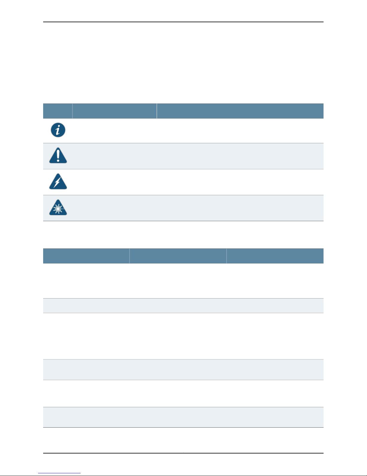
Table 1: Notice Icons
All examples show default file paths. If you do not accept the installation defaults, your
paths will vary from the examples.
Table 1 on page xii defines notice icons used in this guide.
DescriptionMeaningIcon
Indicates important features or instructions.Informational note
Indicates a situation that might result in loss of data or hardware damage.Caution
Alerts you to the risk of personal injury or death.Warning
Alerts you to the risk of personal injury from a laser.Laser warning
Table 2 on page xii defines text conventions used in this guide.
Table 2: Text Conventions
Bold typeface like this
fixed-width font
Keynames linked with a plus (+) sign
Italics
The angle bracket (>)
•
Represents commands and keywords
in text.
•
Represents keywords
•
Represents UI elements
Represents information as displayed on
the terminal screen.
keys simultaneously.
•
Emphasizes words
•
Identifies variables
Indicates navigation paths through the UI
by clicking menu options and links.
ExamplesDescriptionConvention
•
Issue the clock source command.
•
Specify the keyword exp-msg.
•
Click User Objects
user inputRepresents text that the user must type.Bold typeface like this
host1#
show ip ospf
Routing Process OSPF 2 with Router
ID 5.5.0.250
Router is an area Border Router
(ABR)
Ctrl + dIndicates that you must press two or more
•
The product supports two levels of
access, user and privileged.
•
clusterID, ipAddress.
Object Manager > User Objects > Local
Objects
Copyright © 2010, Juniper Networks, Inc.xii
Page 13

Table 3 on page xiii defines syntax conventions used in this guide.
Table 3: Syntax Conventions
About This Guide
ExamplesDescriptionConvention
terminal lengthRepresent keywordsWords in plain text
mask, accessListNameRepresent variablesWords in italics
Words separated by the pipe ( | )
symbol
Words enclosed in brackets followed
by and asterisk ( [ ]*)
Documentation
Table 4 on page xiii describes documentation for the NSM.
Table 4: Network and Security Manager Publications
Network and Security
Manager Installation Guide
variable to the left or right of this symbol. The
keywordor variable can be optional or required.
can be entered more than once.
Represent required keywords or variables.Words enclosed in braces ( { } )
DescriptionBook
Describes the steps to install the NSM management system on a
single server or on separate servers. It also includes information on
how to install and run the NSM user interface. This guide is intended
for IT administrators responsible for the installation or upgrade of
NSM.
diagnostic | lineRepresent a choice to select one keyword or
[ internal | external ]Represent optional keywords or variables.Words enclosed in brackets ( [ ] )
[ level1 | level2 | 11 ]*Represent optional keywords or variables that
{ permit | deny } { in | out } { clusterId
| ipAddress }
Network and Security
Manager Administration
Guide
Network and Security
Manager Configuring
ScreenOS and IDP Devices
Guide
Describes how to use and configure key management features in
the NSM. It provides conceptual information, suggested workflows,
and examples. This guide is best used in conjunction with the NSM
Online Help, which provides step-by-stepinstructions for performing
management tasks in the NSM UI.
This guide is intended for application administrators or those
individuals responsible for owning the server and security
infrastructure and configuring the product for multi-user systems.
It is also intended for device configuration administrators, firewall
and VPN administrators, and network security operation center
administrators.
Provides details about configuring the device features for all
supported ScreenOS and IDP platforms.
xiiiCopyright © 2010, Juniper Networks, Inc.
Page 14

Table 4: Network and Security Manager Publications (continued)
DescriptionBook
Network and Security
Manager Online Help
Network and Security
Manager API Guide
Network and Security
Manager Release Notes
Configuring Infranet
Controllers Guide
Configuring Secure Access
Devices Guide
Configuring EX-series
Switches Guide
Configuring J-series Services
Routers and SRX-series
Services Gateways Guide
Provides procedures for basic tasks in the NSM user interface. It
also includes a brief overview of the NSM system and a description
of the GUI elements.
Provides complete syntax and description of the SOAP messaging
interface to NSM.
Provides the latest information about features, changes, known
problems, resolved problems, and system maximum values. If the
information in the Release Notes differs from the information found
in the documentation set, follow the Release Notes.
Release notes are included on the corresponding software CD and
are available on the Juniper Networks Website.
Provides details about configuring the device features for all
supported Infranet Controllers.
Provides details about configuring the device features for all
supported Secure Access Devices.
Provides details about configuring the device features for all
supported EX-series platforms .
Provides details about configuring the device features for all
supported J-series Services Routers and SRX-series Services
Gateways.
M-series and MX-series
Devices Guide
Requesting Technical Support
Technical product support is availablethrough the Juniper Networks Technical Assistance
Center (JTAC). If you are a customer with an active J-Care or JNASC support contract,
or are covered under warranty, and need postsales technical support, you can access
our tools and resources online or open a case with JTAC.
•
JTAC policies—For a complete understanding of our JTAC procedures and policies,
review the JTAC User Guide located at
http://www.juniper.net/us/en/local/pdf/resource-guides/7100059-en.pdf .
•
Product warranties—For product warranty information, visit
http://www.juniper.net/support/warranty/ .
•
JTAC Hours of Operation —The JTAC centers have resources available 24 hours a day,
7 days a week, 365 days a year.
Provides details about configuring the device features for M-series
and MX-series platforms.
Copyright © 2010, Juniper Networks, Inc.xiv
Page 15

Self-Help Online Tools and Resources
For quick and easy problem resolution, Juniper Networks has designed an online
self-service portal called the Customer Support Center (CSC) that provides you with the
following features:
•
Find CSC offerings: http://www.juniper.net/customers/support/
•
Find product documentation: http://www.juniper.net/techpubs/
•
Find solutions and answer questions using our Knowledge Base: http://kb.juniper.net/
•
Download the latest versions of software and review release notes:
http://www.juniper.net/customers/csc/software/
•
Search technical bulletins for relevant hardware and software notifications:
https://www.juniper.net/alerts/
•
Join and participate in the Juniper Networks Community Forum:
http://www.juniper.net/company/communities/
•
Open a case online in the CSC Case Management tool: http://www.juniper.net/cm/
About This Guide
To verify service entitlement by product serial number, use our Serial Number Entitlement
(SNE) Tool: https://tools.juniper.net/SerialNumberEntitlementSearch/
Opening a Case with JTAC
You can open a case with JTAC on the Web or by telephone.
•
Use the Case Management tool in the CSC at http://www.juniper.net/cm/ .
•
Call 1-888-314-JTAC (1-888-314-5822 toll-free in the USA, Canada, and Mexico).
For international or direct-dial options in countries without toll-free numbers, visit us at
http://www.juniper.net/support/requesting-support.html
xvCopyright © 2010, Juniper Networks, Inc.
Page 16

Copyright © 2010, Juniper Networks, Inc.xvi
Page 17

PART 1
Managing EX-series Switches with NSM
The chapters in Part 1 of the Release 2009.1 version of the NSM Configuration Guide for
EX Series Devices provide an overview of the management system and describe how to
configure features for EX Series devices.
NOTE: Because the NSM device-side configuration guides are not updated
on the same release schedule as the JUNOS releases, consult the JUNOS
Software Documentation for information about configuration settings that
might occur in NSM and not in the device-side configuration guides or vice
versa.
Part 1 contains the following chapters:
•
Configuring User Access and Authentication on page 3
•
Configuring Chassis on page 11
•
Configuring Class of Service on page 15
•
Configuring Ethernet Switching Options on page 35
•
Configuring Firewall Filters on page 43
•
Configuring Policy Options on page 49
•
Configuring Routing Options on page 59
•
Configuring Protocols on page 87
•
Configuring PoE on page 115
•
Configuring SNMP on page 117
•
Configuring Virtual LANs on page 147
•
Configuring a Virtual Chassis on page 149
1Copyright © 2010, Juniper Networks, Inc.
Page 18

Copyright © 2010, Juniper Networks, Inc.2
Page 19

CHAPTER 1
Configuring User Access and
Authentication
This section contains the following:
•
Configuring RADIUS Authentication (NSM Procedure) on page 3
•
Configuring TACACS+ Authentication (NSM Procedure) on page 4
•
Configuring Authentication Order (NSM Procedure) on page 5
•
Configuring User Access (NSM Procedure) on page 6
•
Configuring Template Accounts (NSM Procedure) on page 7
Configuring RADIUS Authentication (NSM Procedure)
To use RADIUS authentication, you must configure at least one RADIUS server. Configuring
RADIUS authentication involves identifying the RADIUS server, specifying the secret
(password)of the RADIUS server, and setting the source address of the device's RADIUS
requests to the loopback address of the device.
To configure RADIUS authentication:
1. In the NSM navigation tree, select Device Manager > Devices.
2. Click the Device Tree tab, and then double-click the device for which you want to
configure RADIUS authentication.
3. Click the Configuration tab. In the configuration tree, select System > Radius Server.
4. Add or modify Radius settings as specified in Table 5 on page 4.
5. Click one:
•
New—Adds a new RADIUS server.
•
OK—Saves the changes.
•
Cancel—Cancels the modifications.
3Copyright © 2010, Juniper Networks, Inc.
Page 20
Table 5: RADIUS Authentication Configuration Details
Your ActionFunctionOption
Specifies the IP address of the RADIUS server.Name
Specifies the shared secret (password) of the
RADIUS server. The secret is stored as an
encrypted value in the configuration database.
Specifies the source address to be included in
the RADIUS server requests by the device. In
most cases, you can use the loopback address
of the device.
Related
Documentation
Secret
Source
Address
Configuring TACACS+ Authentication (NSM Procedure) on page 4•
• Configuring Authentication Order (NSM Procedure) on page 5
• Configuring User Access (NSM Procedure) on page 6
Configuring TACACS+ Authentication (NSM Procedure)
To use TACACS+ authentication, you must configure at least one TACACS+ server.
Configuring TACACS+ authentication involvesidentifying the TACACS+server, specifying
the secret (password) of the TACACS+ server, and setting the source address of the
device's TACACS+ requests to the loopback address of the device.
Enter the IP address of the
RADIUS server.
Enter the shared secret of the
RADIUS server.
Enter the loopback addressof
the device.
To configure TACACS+ authentication:
1. In the NSM navigation tree, select Device Manager > Devices.
2. Click the Device Tree tab and then double-click the device for which you want to
configure TACACS+ authentication.
3. Click the Configuration tab. In the configuration tree, select System > TACACS+
Server.
4. Add or modify TACACS+ settings as specified in Table 6 on page 4.
5. Click one:
•
New—Adds a new TACACS+ server.
•
OK—Saves the changes.
•
Cancel—Cancels the modifications.
Table 6: TACACS+ Authentication Configuration Details
Your ActionFunctionOption
Specifies the IP address of the TACACS+ server.Name
Enter the IP address of the
TACACS+ server.
Copyright © 2010, Juniper Networks, Inc.4
Page 21

Chapter 1: Configuring User Access and Authentication
Table 6: TACACS+ Authentication Configuration Details (continued)
Your ActionFunctionOption
Specifies the shared secret (password) of the
TACACS+ server. The secret is stored as an
encrypted value in the configuration database.
Specifies the source address to be included in
the TACACS+ server requests by the device. In
most cases, you can use the loopback address
of the device.
Related
Documentation
Secret
Source
Address
Configuring RADIUS Authentication (NSM Procedure) on page 3•
• Configuring Authentication Order (NSM Procedure) on page 5
• Configuring User Access (NSM Procedure) on page 6
Configuring Authentication Order (NSM Procedure)
You can configure the device so that user authentication occurs with the local password
first, then with the RADIUS server, and finally with the TACACS+ server.
To configure authentication order:
1. In the NSM navigation tree, select Device Manager > Devices.
2. Click the Device Tree tab and then double-click the device for which you want to
configure authentication order.
Enter the shared secret of the
TACACS+ server.
Enter the loopback address of
the device.
Related
Documentation
3. Click the Configuration tab. In the configurationtree, select System > Authentication
Order.
4. In the Authentication Order workspace, click the New button. The New
authentication-order list appears.
5. To add RADIUS authentication to the authentication order, select radius from the
New authentication-order list.
6. To add TACACS+ authentication to the authentication order, select tacplus from the
New authentication-order list.
7. To add Password authentication to the authentication order, select password from
the New authentication-order list.
•
OK—Saves the changes.
•
Cancel—Cancels the modifications.
Configuring RADIUS Authentication (NSM Procedure) on page 3•
• Configuring TACACS+ Authentication (NSM Procedure) on page 4
• Configuring User Access (NSM Procedure) on page 6
5Copyright © 2010, Juniper Networks, Inc.
Page 22

Configuring User Access (NSM Procedure)
This section includes the following topics:
•
Configuring Login Classes on page 6
•
Configuring User Accounts on page 7
Configuring Login Classes
You can define any number of login classesand then apply one login class to an individual
user account. All users who can log in to the router must be in a login class. With login
classes, you define the following:
•
Access privileges users have when they are logged in to the router
•
Commands and statements that users can and cannot specify
•
How long a login session can be idle before it times out and the user is logged out
To configure login classes:
1. In the NSM navigation tree, select Device Manager > Devices.
2. Click the Device Tree tab and then double-click the device for which you want to
configure a login class.
3. Click the Configuration tab. In the configuration tree, select System > Login > Class.
4. Add or modify login class settings as specified in Table 7 on page 6.
5. Click one:
•
New—Adds a new login class.
•
OK—Saves the changes.
•
Cancel—Cancels the modifications.
Table 7: Login Class Authentication Configuration Details
Your ActionFunctionOption
Enter a name for the login class.Specifies a name for the login class.Name
Allow Commands
Specifies the operational mode
commands that members of a login
class can use.
Login > Class > Permissions
Permissions
to be provided on the device.
Enter the command name enclosed
in quotation marks. For example,
“request system reboot”.
Enter a new permission.Configures the login access privileges
Copyright © 2010, Juniper Networks, Inc.6
Page 23
Configuring User Accounts
User accounts provide one way for users to access the device. (Users can access the
router without accounts if you configured RADIUS or TACACS+servers.) For each account,
define the login name for the user and, optionally, information that identifies the user.
After you have created an account, a home directory is created for the user.
To configure user accounts:
1. In the NSM navigation tree, select Device Manager > Devices.
2. Click the Device Tree tab and then double-click the device for which you want to
configure login class.
3. Click the Configuration tab. In the configuration tree, select System > Login > User.
4. Add or modify login class settings as specified in Table 8 on page 7.
5. Click one:
•
Chapter 1: Configuring User Access and Authentication
New—Adds a new user account.
•
OK—Saves the changes.
•
Cancel—Cancels the modifications.
Table 8: User Authentication Configuration Details
Name
name.
Login > User > Authentication
Specifies the user’s password.Plain Text Password
Value
Related
Documentation
Configuring RADIUS Authentication (NSM Procedure) on page 3•
• Configuring TACACS+ Authentication (NSM Procedure) on page 4
• Configuring Authentication Order (NSM Procedure) on page 5
Configuring Template Accounts (NSM Procedure)
Your ActionFunctionOption
Enter a unique name for the user.Identifies the user with a unique
Select the class name.Specifies the user's login class.Class
Enter the plain text password for
the user.
You can create template accounts that are shared by a set of users when you are using
RADIUS or TACACS+ authentication. When a user is authenticatedby a template account,
7Copyright © 2010, Juniper Networks, Inc.
Page 24

the CLI username is the login name, and the privileges, file ownership, and effective user
ID are inherited from the template account.
To configure template accounts, follow these procedures:
•
Creating a Remote Template Account on page 8
•
Creating a Local Template Account on page 9
Creating a Remote Template Account
You can create a remote template that is applied to users authenticated by RADIUS or
TACACS+ that do not belong to a local template account.
By default, JUNOS software with enhanced services uses the remote template account
when:
•
The authenticated user does not exist locally on the Services Router.
•
The authenticated user's record in the RADIUS or TACACS+ server specifies local user,
or the specified local user does not exist locally on the device.
The following procedure creates a sample user named remote that belongs to the operator
login class.
To create a remote template account:
1. In the NSM navigation tree, select Device Manager > Devices.
2. Click the Device Tree tab and then double-click the device for which you want to
create a remote template account.
3. Click the Configuration tab. In the configuration tree, select System > Login > User.
4. Add or modify login class settings as specified in Table 9 on page 8.
5. Click one:
•
New—Creates a new remote template account.
•
OK—Saves the changes.
•
Cancel—Cancels the modifications.
Table 9: Remote Template Account Details
Your ActionFunctionOption
Enter the user name. For example, type
remote.
Enter the number associated with the
login account.
Selectthe login class. For example, select
operator.
Uid
Specifies a name for the user name.Name
Specifies the user identifier for a
login account.
Specifies the login class for the user.Class
Copyright © 2010, Juniper Networks, Inc.8
Page 25

Creating a Local Template Account
You can create a local template that is applied to users authenticated by RADIUS or
TACACS+ that are assigned to the local template account. You use local template
accounts when you need different types of templates. Each template can define a
different set of permissions appropriate for the group of users who use that template.
The following procedure creates a sample user named admin that belongs to the
superuser login class.
To create a local template account:
1. In the NSM navigation tree, select Device Manager > Devices.
2. Click the Device Tree tab and then double-click the device for which you want to
create a local template account.
3. Click the Configuration tab. In the configuration tree, select System > Login > User.
4. Add or modify login class settings as specified in Table 10 on page 9.
Chapter 1: Configuring User Access and Authentication
Related
Documentation
5. Click one:
•
New—Creates a new local template account.
•
OK—Saves the changes.
•
Cancel—Cancels the modifications.
Table 10: Local Template Account Details
Your ActionFunctionOption
Specifies a name for the user name.Name
Uid
• Configuring RADIUS Authentication (NSM Procedure) on page 3
• Configuring TACACS+ Authentication (NSM Procedure) on page 4
• Configuring Authentication Order (NSM Procedure) on page 5
Specifies the user identifier for a
login account.
Specifies the login class for the user.Class
Enter the user name. For example, type
admin.
Enter the number associated with the
login account.
Selectthe login class. For example, select
superuser.
9Copyright © 2010, Juniper Networks, Inc.
Page 26

Copyright © 2010, Juniper Networks, Inc.10
Page 27

CHAPTER 2
Configuring Chassis
This section contains the following:
•
Configuring Aggregated Devices (NSM Procedure) on page 11
•
Configuring Chassis Alarms (NSM Procedure) on page 12
•
Configuring Routing Engine Redundancy (NSM Procedure) on page 13
Configuring Aggregated Devices (NSM Procedure)
The JUNOS Software supports the aggregation of physical devices into the defined virtual
links, such as the link aggregation of Ethernet interfaces defined by the IEEE 802.3ad
standard. You can configure the properties for Ethernet and sonet aggregated devices
on the router.
To configure the aggregated devices on the router:
1. In the NSM navigation tree, select Device Manager > Devices.
2. Click the Device Tree tab, and then double-click the device to select it.
3. Click the Configuration tab. In the configuration tree, expand Chassis > Aggregated
Devices.
4. Add or modify the settings as specified in Table 11 on page 12.
5. Click one:
•
OK—Saves the changes.
•
Cancel—Cancels the modifications.
11Copyright © 2010, Juniper Networks, Inc.
Page 28

Table 11: Aggregated Devices Configuration Details
Your ActionTask
Related
Documentation
Configure properties for
Ethernet aggregated
devices.
Configure properties for
sonet aggregated devices.
1. Click Ethernet next to Aggregated Devices.
2. Enter the number of aggregated logical devices available to
the router.
Range: 1 through 256 devices
3. Click Lacp next to Ethernet.
4. In the System Priority box, enter the priority for the aggregated
Ethernet system.
5. Click Link Protection next to Lacp.
6. Select the Non Revertive check box if you want to disable the
ability to switch to a better priority link (if one is available) once
a link is established as active and a collection or distribution is
enabled.
1. Click Sonet next to Aggregated Devices.
2. From the Device Count list, select the number of aggregated
logical devices available to the router.
Range: 1 through 16 Devices
Configuring Chassis Alarms (NSM Procedure) on page 12•
• Configuring a T640 Router on a Routing Matrix (NSM Procedure)
• Configuring Routing Engine Redundancy (NSM Procedure) on page 13
• Configuring a Routing Engine to Reboot or Halt on Hard Disk Errors (NSM Procedure)
Configuring Chassis Alarms (NSM Procedure)
You can configure the chassis alarms for an interface type to trigger a red or yellow alarm
or to ignore an alarm. Various conditions relatedto the chassis components trigger yellow
and red alarms.
To configure chassis alarm on the router:
1. In the NSM navigation tree, select Device Manager > Devices.
2. Click the Device Tree tab, and then double-click the device to select it.
3. Click the Configuration tab. In the configuration tree, expand Chassis > Alarm.
4. Add or modify the alarm settings as specified in Table 12 on page 13.
5. Click one:
•
OK—Saves the changes.
•
Cancel—Cancels the modifications.
Copyright © 2010, Juniper Networks, Inc.12
Page 29

Table 12: Chassis Alarms Configuration Details
Your ActionTask
Chapter 2: Configuring Chassis
1. Select the interface type listed next to Alarm.
2. Select the alarm type for the chassis condition for each
interface type.
Related
Documentation
Configuring the alarm type.
Configuring Aggregated Devices (NSM Procedure) on page 11•
• Configuring Chassis FPC (NSM Procedure)
• Configuring Routing Engine Redundancy (NSM Procedure) on page 13
Configuring Routing Engine Redundancy (NSM Procedure)
You can configure redundancy properties for routers that have multiple Routing Engines
or these multiple switching control boards: Switching and Forwarding Modules (SFMs),
System and Switch Boards (SSBs), Forwarding Engine Boards (FEBs), or Compact
Forwarding Engine Boards (CFEBs).
To configure routing engine redundancy in NSM:
1. In the NSM navigation tree, select Device Manager > Devices.
2. Click the Device Tree tab, and then double-click the device to select it.
3. Click the Configuration tab. In the configuration tree, select Chassis > Redundancy.
4. Add or modify settings as specified in Table 13 on page 13.
5. Click one:
•
OK—Saves the changes.
•
Cancel—Cancels the modifications.
Table 13: Chassis Redundancy Configuration Details
Your ActionTask
Configure redundancy
options.
Instruct the backup router to
take mastership if it detects
hard disk errors or a loss of a
keepalive signal from the
master Routing Engine.
1. In the Comment box, enter the comment.
2. From the keepalive list, select the time before the backup
router takes mastership when it detects loss of the keepalive
signal.
Range: 2 through 10,000
1. Click Failover next to Redundancy.
2. In the Comment box, enter the comment.
3. Select the type of failover.
13Copyright © 2010, Juniper Networks, Inc.
Page 30

Table 13: Chassis Redundancy Configuration Details (continued)
Your ActionTask
Related
Documentation
For routing platforms with
two Routing Engines,
configure a master Routing
1. Click Graceful Switchover next to Redundancy.
2. In the Comment box, enter the comment.
Engine to switch over
gracefully to a backup
Routing Engine without
interruption to packet
forwarding.
Sets the function of the
Routing Engine for the
specified slot. By default, the
Routing Engine in slot 0 is the
master Routing Engine and
the Routing Engine in slot 1 is
the backup Routing Engine.
• Configuring Aggregated Devices (NSM Procedure) on page 11
• Configuring a T640 Router on a Routing Matrix (NSM Procedure)
• Configuring a Routing Engine to Reboot or Halt on Hard Disk Errors (NSM Procedure)
1. Click Routing Engine next to Redundancy.
2. From the Name list, select the slot number.
3. In the Comment box, enter the comment.
4. Select the function of the Routing Engine for the specified slot.
5. Select one of the following:
•
master—To configure the routing engine to be the master.
•
backup—To configure the routing engine to be the backup.
•
disabled—To disable the routing engine.
Copyright © 2010, Juniper Networks, Inc.14
Page 31

CHAPTER 3
Configuring Class of Service
This section contains the following:
•
Configuring CoS Classifiers (NSM Procedure) on page 15
•
Configuring CoS Code Point Aliases (NSM Procedure) on page 17
•
Configuring CoS Drop Profile (NSM Procedure) on page 19
•
Configuring CoS Forwarding Classes (NSM Procedure) on page 21
•
Configuring CoS Interfaces (NSM Procedure) on page 22
•
Configuring CoS Rewrite Rules (NSM Procedure) on page 28
•
Configuring CoS Schedulers (NSM Procedure) on page 31
•
Configuring CoS and Applying Scheduler Maps (NSM Procedure) on page 32
Configuring CoS Classifiers (NSM Procedure)
Packet classification associates incoming packets with a particular class-of-service
(Cos) servicing level. Classifiers associatepackets with a forwarding class and loss priority
and, based on the associated forwarding class, assign packets to output queues. JUNOS
software supports two general types of classifiers:
•
Behavior aggregate or CoS value traffic classifiers—Examines the CoS value in the
packet header. The value in this single field determines the CoS settings applied to the
packet. BA classifiers allow you to set the forwarding class and loss priority of a packet
based on the Differentiated Services code point (DSCP) value, IP precedence value,
and IEEE 802.1p value. The default classifier is based on the DSCP value.
•
Multifield traffic classifiers—Examines multiple fields in the packet such as source and
destination addresses and source and destination port numbers of the packet. With
multifield classifiers, you set the forwarding class and loss priority of a packet based
on firewall filter rules.
To configure and apply behavior aggregate classifiers for the switch:
1. In the navigation tree, select Device Manager > Devices.
2. Click the Device Tree tab, and then double-click the device for which you want to
configure and apply behavior aggregate classifiers.
3. Click the Configuration tab. In the configuration tree expand Class of Service.
15Copyright © 2010, Juniper Networks, Inc.
Page 32

4. Select Classifiers.
5. Add or modify settings as specified in Table 14 on page 16.
6. Click one:
•
OK—Saves the changes.
•
Cancel—Cancels the modifications.
NOTE: After you make changes to a device configuration,you must push that
updateddevice configuration to the physical security device for those changes
to take effect. You can update multiple devices at one time. See the Network
and Security Manager Administration Guide for more information.
Table 14: Configuring and Applying Behavior Aggregate Classifiers
ActionTask
Configure behavior aggregate
classifiers for DiffServ CoS.
Configure a best-effort
forwarding class classifier.
Configure an expedited
forwarding class classifier.
1. Click Add new entry next to Dscp.
2. In the Name box, type the name of the behavior aggregate classifier—for example,
ba-classifier.
3. In the Import box, type the name of the default DSCP map.
1. Click Add new entry next to Forwarding class.
2. In the Class name box, type the name of the previously configured best-effort forwarding
class—for example, be-class.
3. Click Add new entry next to Loss priority.
4. From the Loss val list, select high.
5. Click Add new entry next to Code points.
6. In the Value box, type the value of the high-priority code point for best-effort traffic—for
example, 00001.
7. Click OK three times.
1. Click Add new entry next to Forwarding class.
2. In the Class name box, type the name of the previously configured expedited
forwarding—for example, class-ef-class.
3. Click Add new entry next to Loss priority.
4. From the Loss val list, select high.
5. Click Add new entry next to Code points.
6. In the Value box, type the value of the high-priority code point for expedited forwarding
traffic—for example, 101111.
7. Click OK three times.
Copyright © 2010, Juniper Networks, Inc.16
Page 33

Chapter 3: Configuring Class of Service
Table 14: Configuring and Applying Behavior Aggregate Classifiers (continued)
ActionTask
Configurean assuredforwarding
class classifier.
Apply the behavior aggregate
classifier to an interface.
Related
Documentation
• Configuring CoS Drop Profile (NSM Procedure) on page 19
1. Click Add new entry next to Forwarding class.
2. In the Class name box, type the name of the previously configured assured forwarding—for
example, class-af-class.
3. Click Add new entry next to Loss priority.
4. From the Loss val list, select high.
5. Click Add new entry next to Code points.
6. In the Value box, type the value of the high-priority code point for assured forwarding
traffic—for example, 001100.
7. Click OK three times.
1. Click Add new entry next to Interfaces.
2. In the Interface name box, type the name of the interface—for example, ge-0/0/0.
3. Click Add new entry next to Unit.
4. In the Unit number box, type the logical interface unit number—for example, 0.
5. Click Configure next to Classifiers.
6. In the Classifiers box, under Dscp, type the name of the previously configured behavior
aggregate classifier—for example, ba-classifier.
7. Click OK.
Configuring CoS Code Point Aliases (NSM Procedure) on page 17•
• Configuring CoS Forwarding Classes (NSM Procedure) on page 21
• Configuring CoS Interfaces (NSM Procedure) on page 22
• Configuring CoS Rewrite Rules (NSM Procedure) on page 28
• Configuring CoS Schedulers (NSM Procedure) on page 31
• Configuring CoS and Applying Scheduler Maps (NSM Procedure) on page 32
Configuring CoS Code Point Aliases (NSM Procedure)
You can use code-point aliases to streamline the process of configuring CoS features on
your device. A code-point alias assigns a name to a pattern of code-point bits. You can
use this name instead of the bit pattern when you configure other CoS components such
as classifiers, drop-profile maps, and rewrite rules.
To configure code-point aliases:
17Copyright © 2010, Juniper Networks, Inc.
Page 34

1. In the navigation tree, select Device Manager > Devices.
2. Click the Device Tree tab, and then double-click the device for which you want to
configure CoS code point aliases.
3. Click the Configuration tab. In the configuration tree, expand Class of Service.
4. Select Code Point Aliases.
5. Add or modify the settings as specified in Table 15 on page 18
6. Click one:
•
OK—Saves the changes.
•
Cancel—Cancels the modifications.
NOTE: After you make changes to a device configuration,you must push that
updateddevice configuration to the physical security device for those changes
to take effect. You can update multiple devices at one time. See the Network
and Security Manager Administration Guide for more information.
Table 15: Configuring Code Point Aliases
ActionTask
Assign an alias to the dscp code
point.
Related
Documentation
• Configuring CoS Drop Profile (NSM Procedure) on page 19
• Configuring CoS Forwarding Classes (NSM Procedure) on page 21
• Configuring CoS Interfaces (NSM Procedure) on page 22
• Configuring CoS Rewrite Rules (NSM Procedure) on page 28
• Configuring CoS Schedulers (NSM Procedure) on page 31
• Configuring CoS and Applying Scheduler Maps (NSM Procedure) on page 32
1. In the Configuration tree, expand Code Point Aliases.
2. Select Dscp.
3. Click the Add New icon.
4. In the Name box, type the alias that you want to assign to the code point—for example,
my1.
5. In the Bits box, type the code point—for example, 110001.
6. Click OK.
Configuring CoS Classifiers (NSM Procedure) on page 15•
Copyright © 2010, Juniper Networks, Inc.18
Page 35

Configuring CoS Drop Profile (NSM Procedure)
Drop profiles provide a congestion management mechanism that enables a switch or
routing platform to drop the arriving packets when queue buffers become full or begin
to overflow. Drop profiles define the meanings of loss priorities. When you configure drop
profiles you are essentially setting the value for queue fullness. The queue fullness
represents the percentage of the memory used to store packets in relation to the total
amount of memory that has been allocated for that specific queue. The queue fullness
defines the delay-buffer bandwidth, which provides packet buffer space to absorb burst
traffic up to the specified duration of delay. Once the specified delay buffer becomes
full, packets with 100 percent drop probability are dropped from the tail of the buffer.
You specify drop probabilities in the drop profile section of the CoS configurationhierarchy
and reference them in each scheduler configuration. By default, if you do not configure
any drop profile then the drop profile that is in effect functions as the primary mechanism
for managing congestion. In the default tail drop profile, when the fill level is 0 percent,
the drop probability is 0 percent. When the fill level is 100 percent, the drop probability
is 100 percent.
Chapter 3: Configuring Class of Service
To configure drop profiles in NSM:
1. In the navigation tree, select Device Manager > Devices.
2. Click the Device Tree tab, and then double-click the device for which you want to
configure drop profiles.
3. Click the Configuration tab. In the configuration tree expand Class of Service.
4. Select Drop Profiles.
5. Add or modify the drop profiles as specified in Table 16 on page 19.
6. Click one:
•
OK—Saves the changes.
•
Cancel—Cancels the modifications.
NOTE: After you make changes to a device configuration,you must push that
updateddevice configuration to the physical security device for those changes
to take effect. You can update multiple devices at one time. See Updating
Devices section in the Network and Security Manager Administration Guide for
more information.
Table 16: Drop Profile Configuration Fields
Drop Profile
Your ActionFunctionOption
19Copyright © 2010, Juniper Networks, Inc.
Page 36

Table 16: Drop Profile Configuration Fields (continued)
Your ActionFunctionOption
Comment
Fill Level
Specifies the drop profile name.Name
Specifies the comment for the drop
profile.
Specifies the fill level for the drop profile.Name
Specifies the comment for the fill levelComment
1. Click the New button or Edit button
in the Drop Profile interface.
2. Enter the drop profile name in the
Name box.
1. Click the New button or Edit button
in the Drop Profile interface.
2. Enter the comment for the drop
profile in the Comment box.
1. On Drop Profile interface click the
New button or select a profile and
click the Edit button.
2. Expand the Drop Profile tree and
select Fill Level.
3. Click the New button or select a fill
level and click the Edit button.
4. Select a value from Name list.
1. On the Drop Profileinterfaceclick the
New button or select a profile and
click the Edit button.
2. Expand the Drop Profile tree and
select Fill Level.
3. Click the New button or select a fill
level and click the Edit button.
4. Enter a comment in the Comment
box.
Related
Documentation
Configuring CoS Classifiers (NSM Procedure) on page 15•
• Configuring CoS Code Point Aliases (NSM Procedure) on page 17
• Configuring CoS Forwarding Classes (NSM Procedure) on page 21
• Configuring CoS Interfaces (NSM Procedure) on page 22
• Configuring CoS Rewrite Rules (NSM Procedure) on page 28
• Configuring CoS Schedulers (NSM Procedure) on page 31
• Configuring CoS and Applying Scheduler Maps (NSM Procedure) on page 32
Copyright © 2010, Juniper Networks, Inc.20
Page 37

Configuring CoS Forwarding Classes (NSM Procedure)
Forwarding classes allow you to group packets for transmission. Based on forwarding
classes, you assign packets to output queues.
By default, four categories of forwarding classes are defined: best effort, assured
forwarding, expedited forwarding, and network control.
NOTE: EX-series switches support up to 16 forwarding classes.
To configure CoS forwarding classes:
1. In the navigation tree, select Device Manager > Devices.
2. Click the Device Tree tab, and then double-click the device for which you want to
configure CoS forwarding classes.
3. Click the Configuration tab. In the configuration tree, expand Class of Service.
Chapter 3: Configuring Class of Service
4. Select Forwarding Classes.
5. Add or modify settings as specified in Table 17 on page 21.
6. Click one:
•
OK—Saves the changes.
•
Cancel—Cancels the modifications.
NOTE: After you make changes to a device configuration,you must push that
updateddevice configuration to the physical security device for those changes
to take effect. You can update multiple devices at one time. See the Network
and Security Manager Administration Guide for more information.
Table 17: Assigning Forwarding Classes to Output Queues
ActionTask
Assign best-effort traffic to queue 0.
1. Select Queue and click Add new entry.
2. In the Queue num box, type 0.
3. In the Class name box, type the previously configured name of the best-effort
class—for example, be-class.
4. Click OK.
21Copyright © 2010, Juniper Networks, Inc.
Page 38

Table 17: Assigning Forwarding Classes to Output Queues (continued)
ActionTask
Assign expedited forwarding traffic to
queue 1.
Configure an assured forwarding class
classifier.
Related
Documentation
Configuring CoS Classifiers (NSM Procedure) on page 15•
• Configuring CoS Code Point Aliases (NSM Procedure) on page 17
• Configuring CoS Drop Profile (NSM Procedure) on page 19
• Configuring CoS Interfaces (NSM Procedure) on page 22
• Configuring CoS Rewrite Rules (NSM Procedure) on page 28
• Configuring CoS Schedulers (NSM Procedure) on page 31
• Configuring CoS and Applying Scheduler Maps (NSM Procedure) on page 32
1. Select Queue and click Add new entry.
2. In the Queue num box, type 1.
3. In the Class name box, type the previously configured name of the expedited
forwarding class—for example, ef-class.
4. Click OK.
1. Select Queue and click Add new entry.
2. In the Queue num box, type 3.
3. In the Class name box, type the previously configured name of the assured
forwarding class—for example, af-class.
4. Click OK.
Configuring CoS Interfaces (NSM Procedure)
An interface is configured for optimal performance in a high-traffic network. This feature
enables you to configure interface-specific CoS properties for incoming packets.
To configure CoS interfaces in NSM:
1. In the navigation tree, select Device Manager > Devices.
2. Click the Device Tree tab, and then double-click the device for which you want to
configure CoS interfaces.
3. Click the Configuration tab. In the configuration tree, expand Class of Service.
4. Select Interfaces.
5. Add or modify the interfaces as specified in Table 18 on page 23.
6. Click one:
•
OK—Saves the changes.
•
Cancel—Cancels the modifications.
Copyright © 2010, Juniper Networks, Inc.22
Page 39

NOTE: After you make changes to a device configuration,you must push that
updateddevice configuration to the physical security device for those changes
to take effect. You can update multiple devices at one time. See the Network
and Security Manager Administration Guide for more information.
Table 18: Interfaces Configuration Fields
Interface
Chapter 3: Configuring Class of Service
Your ActionFunctionOption
Comment
Scheduler Map
Specifies the interface name.Name
Specifies the comment for the
interface.
Specifies the scheduler
configuration mapped to the
forwarding class.
1. Expand the Interfaces tree
and select Interface.
2. Click the New button or
select an interface and
click the Edit button in
Interface.
3. Enter the interface name
in the Name box.
1. Expand the Interfaces tree
and select Interface.
2. Click the New button or
select an interface and
click the Edit button in
Interface.
3. Enter the comment for the
interface in the Comment
box.
1. Expand the Interfaces tree
and select Interface.
2. Click the New button or
select an interface and
click the Edit button in
Interface.
3. Select the scheduler map
from the list.
Scheduler Map Chassis
Specifies the scheduler
configuration mapped to the
forwarding class for the
particular chassis in the
chassis queue.
1. Expand the Interfaces tree
and select Interface.
2. Click the New button or
select an interface and
click the Edit button in
Interface.
3. Select the scheduler map
chassis from the list.
23Copyright © 2010, Juniper Networks, Inc.
Page 40

Table 18: Interfaces Configuration Fields (continued)
Your ActionFunctionOption
Input Traffic Control Profile
Input Traffic Control Profile
Remaining
Output Traffic Control Profile
Applies an input traffic
scheduling and shaping profile
to the logical interface.
Applies an input traffic
scheduling and shaping profile
for remaining traffic to the
logical interface.
Applies an output traffic
scheduling and shaping profile
to the logical interface.
1. Click the New button or
select an interface and
click the Edit button in
Interface.
2. Expand the Interface tree
and select Input Traffic
Control Profile.
3. Specify the comment and
the profile name.
4. Click Ok.
1. Click the New button or
select an interface and
click the Edit button in
Interface.
2. Expand the Interface tree
and select Input Traffic
ControlProfileRemaining.
3. Specify a comment and a
profile name.
4. Click Ok.
1. Click the New button or
select an interface and
click the Edit button in
Interface.
2. Expand the Interface tree
and select Output Traffic
Control Profile.
3. Specify a comment and a
profile name.
4. Click Ok.
Output Traffic Control Profile
Remaining
Applies an output traffic
scheduling and shaping profile
for remaining traffic to the
logical interface.
Copyright © 2010, Juniper Networks, Inc.24
1. Click the New button or
select an interface and
click the Edit button in
Interface.
2. Expand the Interface tree
and select Output Traffic
ControlProfileRemaining.
3. Specify a comment and a
profile name.
4. Click Ok.
Page 41

Chapter 3: Configuring Class of Service
Table 18: Interfaces Configuration Fields (continued)
Your ActionFunctionOption
Shaping Rate
Unit
Interface Set
Shapes the output of the
physical interface, so that the
interface transmits less traffic
than it is physically capable of
carrying.
Sets the units that need to be
allocated to the specific
forwarding class and
scheduling map.
1. Click the New button or
select an interface and
click the Edit button in
Interface.
2. Expand Interface tree and
select Shaping Rate.
3. Specify the comment and
the rate
4. Click Ok.
1. Click the New button or
select an interface and
click the Edit button in
Interface.
2. Expand Interface tree and
select Unit.
3. Specify the Unit,
Classifiers, Output Traffic
Control Profile and
Shaping Rate.
4. Click Ok.
Name
Comment
Internal Node
Specifies the interface set
name.
Specifies the comment for the
interface.
Sets the scheduler node as
internal, allowing resource
scheduling to be applied
equally to interface sets that
include child nodes and those
that do not include child
nodes.
1. Expand the Interfaces tree
and select Interface Set.
2. Click the New button or
select an interface set and
click the Edit button.
3. Select the name from the
list.
1. Expand the Interfaces tree
and select Interface Set.
2. Click the New button or
select an interface set and
click the Edit button.
3. Enter the comment.
1. Expand the Interfaces tree
and select Interface Set.
2. Click the New button or
select an interface set and
click the Edit button.
3. Set the internal node.
25Copyright © 2010, Juniper Networks, Inc.
Page 42

Table 18: Interfaces Configuration Fields (continued)
Your ActionFunctionOption
Excess Bandwidth Share
Input Excess Bandwidth Share
Sets the excess bandwidth
sharing value.
Sets the excess input
bandwidth sharing value.
1. Expand the Interfaces tree
and select Interface Set.
2. Click the New button or
select an interface set and
click the Edit button.
3. Expand interface—settree
and select Excess
Bandwidth Share.
4. Specify the comment and
proportion.
5. Click Ok.
1. Expand the Interfaces tree
and select Interface Set.
2. Click the New button or
select an interface set and
click the Edit button.
3. Expand interface—settree
and select Input Excess
Bandwidth Share.
4. Specify the comment and
proportion.
5. Click Ok.
Input Traffic Control Profile
Applies an input traffic
scheduling and shaping profile
to the logical interface.
1. Expand the Interfaces tree
and select Interface Set.
2. Click the New button or
select an interface set and
click the Edit button.
3. Expand interface—settree
and select Input Traffic
Control Profile.
4. Specify the comment and
profile name.
5. Click Ok.
Copyright © 2010, Juniper Networks, Inc.26
Page 43

Chapter 3: Configuring Class of Service
Table 18: Interfaces Configuration Fields (continued)
Your ActionFunctionOption
Input Traffic Control Profile
Remaining
Output Traffic Control Profile
Applies an input traffic
scheduling and shaping profile
for remaining traffic to the
logical interface.
Applies an output traffic
scheduling and shaping profile
to the logical interface.
1. Expand the Interfaces tree
and select Interface Set.
2. Click the New button or
select an interface set and
click the Edit button.
3. Expand interface—settree
and select Input Traffic
Control Profile Remaining.
4. Specify the comment and
profile name.
5. Click Ok.
1. Expand the Interfaces tree
and select Interface Set.
2. Click the New button or
select an interface set and
click the Edit button.
3. Expand interface—settree
and select Output Traffic
Control Profile.
4. Specify the comment and
profile name.
5. Click Ok.
Related
Documentation
Output Traffic Control Profile
Remaining
Applies an output traffic
scheduling and shaping profile
for remaining traffic to the
logical interface.
1. Expand the Interfaces tree
and select Interface Set.
2. Click the New button or
select an interface set and
click the Edit button.
3. Expand interface—settree
and select Output Traffic
Control Profile Remaining.
4. Specify the comment and
profile name.
5. Click Ok.
Configuring CoS Classifiers (NSM Procedure) on page 15•
• Configuring CoS Code Point Aliases (NSM Procedure) on page 17
• Configuring CoS Drop Profile (NSM Procedure) on page 19
• Configuring CoS Forwarding Classes (NSM Procedure) on page 21
• Configuring CoS Rewrite Rules (NSM Procedure) on page 28
• Configuring CoS Schedulers (NSM Procedure) on page 31
27Copyright © 2010, Juniper Networks, Inc.
Page 44

• Configuring CoS and Applying Scheduler Maps (NSM Procedure) on page 32
Configuring CoS Rewrite Rules (NSM Procedure)
You configure rewrite rules to alter CoS values in outgoing packets on the outbound
interfaces of a device to match the policies of a targeted peer. Policy matching allows
the downstream router in a neighboring network to classify each packet into the
appropriate service group.
In addition, you often need to rewrite a given marker such as IP precedence, DSCP, or
IEEE 802.1p at the switch's inbound interfaces to accommodate behavior aggregate (BA)
classification by core devices.
You do not need to explicitly apply rewrite rules to interfaces. By default, rewrite rules
are applied to routed packets.
To configure CoS rewrite rules:
1. In the navigation tree, select Device Manager > Devices
2. Click the Device Tree tab, and then double-click the device for which you want to
configure CoS rewrite rules.
3. Click the Configuration tab. In the configuration tree, expand Class of Service
4. Select Rewrite Rules.
5. Add or modify settings as specified in Table 19 on page 28.
6. Click one:
•
OK—Saves the changes.
•
Cancel—Cancels the modifications.
NOTE: After you make changes to a device configuration,you must push that
updateddevice configuration to the physical security device for those changes
to take effect. You can update multiple devices at one time. See the Network
and Security Manager Administration Guide for more information.
Table 19: Configuring and Applying Rewrite Rules
ActionTask
Configure rewrite
rules for DiffServ CoS.
1. Click Configure next to Rewrite Rules.
2. Click Add new entry next to Dscp.
3. In the Name box, type the name of the rewrite rules—for example,
rewrite-dscps.
Copyright © 2010, Juniper Networks, Inc.28
Page 45

Chapter 3: Configuring Class of Service
Table 19: Configuring and Applying Rewrite Rules (continued)
ActionTask
Configure best-effort
forwarding class
rewrite rules.
Configure expedited
forwarding class
rewrite rules.
1. Click Add new entry next to Forwarding class.
2. In the Queue num box, type 1.
3. In the Class name box, type the name of the previously configured
best-effort forwarding class—for example, be-class.
4. Click Add new entry next to Loss priority.
5. From the Loss val list, select low.
6. In the Code point box, type the value of the low-priority code point
for best-effort traffic—for example, 000000.
7. Click OK.
8. Click Add new entry next to Loss priority.
9. From the Loss val list, select high.
10. In the Code point box, type the value of the high-priority code point
for best-effort traffic—for example, 000001.
11. Click OK twice.
1. Click Add new entry next to Forwarding class.
2. In the Class name box, type the name of the previously configured
expedited forwarding class—for example, ef-class.
3. Click Add new entry next to Loss priority.
4. From the Loss val list, select low.
5. In the Code point box, type the value of the low-priority code point
for expedited forwarding traffic—for example, 101110.
6. Click OK.
7. Click Add new entry next to Loss priority.
8. From the Loss val list, select high.
9. In the Code point box, type the value of the high-priority code point
for expedited forwarding traffic—for example, 101111.
10. Click OK twice.
29Copyright © 2010, Juniper Networks, Inc.
Page 46

Table 19: Configuring and Applying Rewrite Rules (continued)
Configure assured forwarding class rewrite
rules.
Apply rewrite rules to an interface.
1. Click Add new entry next to Forwarding
class.
2. In the Class name box, type the name of the
previously configured expedited forwarding
class—for example, af-class.
3. Click Add new entry next to Loss priority.
4. From the Loss val list, select low.
5. In the Code point box, type the value of the
low-priority code point for assured
forwarding traffic—for example, 001010.
6. Click OK.
7. Click Add new entry next to Loss priority.
8. From the Loss val list, select high.
9. In the Code point box, type the value of the
high-priority code point for assured
forwarding traffic—for example, 001100.
10. Click OK twice.
1. Click Add new entry next to Interfaces.
2. In the Interface name box, type the name of
the interface—for example, ge-0/0/0.
3. Click Add new entry next to Unit.
4. In the Unit number box, type the logical
interface unit number—for example, 0.
5. Click Configure next to Rewrite rules.
6. In the Rewrite rules name box, under Dscp,
type the name of the previously configured
rewrite rules—for example, rewrite-dscps.
7. Click OK.
Related
Documentation
Configuring CoS Classifiers (NSM Procedure) on page 15•
• Configuring CoS Code Point Aliases (NSM Procedure) on page 17
• Configuring CoS Drop Profile (NSM Procedure) on page 19
• Configuring CoS Forwarding Classes (NSM Procedure) on page 21
• Configuring CoS Interfaces (NSM Procedure) on page 22
• Configuring CoS Schedulers (NSM Procedure) on page 31
• Configuring CoS and Applying Scheduler Maps (NSM Procedure) on page 32
Copyright © 2010, Juniper Networks, Inc.30
Page 47

Configuring CoS Schedulers (NSM Procedure)
Using schedulers, you can assign attributes to queues and thereby provide congestion
control for a particular class of traffic. These attributes include the amount of interface
bandwidth, memory buffer size, transmit rate, and schedule priority.
To configure CoS schedulers:
1. In the navigation tree, select Device Manager > Devices.
2. Click the Device Tree tab, and then double-click the device for which you want to
configure CoS schedulers.
3. Click the Configuration tab. In the configuration tree expand Class of Service.
4. Select Schedulers.
5. Add or modify the settings as specified in Table 20 on page 31.
6. Click one:
Chapter 3: Configuring Class of Service
•
OK—Saves the changes.
•
Cancel—Cancels the modifications.
NOTE: After you make changes to a device configuration,you must push that
updateddevice configuration to the physical security device for those changes
to take effect. You can update multiple devices at one time. See the Network
and Security Manager Administration Guide for more information.
Table 20: Configuring Schedulers
ActionTask
Specify the buffer size.
1. Click the Add New icon.
2. Expand Buffer Size.
3. Select Percent.
4. Under Percent, select the appropriate option:
•
To specify no buffer size, select None.
•
To specify buffer size as a percentage of the total buffer, select percent and type an integer
from 1 through 100.
•
To specify buffer size as the remaining available buffer, select remainder.
5. Click OK.
31Copyright © 2010, Juniper Networks, Inc.
Page 48

Table 20: Configuring Schedulers (continued)
ActionTask
Configure drop profile
map.
Specify the transmit rate.
Related
Documentation
1. Click the Add New icon.
2. Select drop-profile-map.
3. In the Loss Priority box, select the required loss priority—for example, high.
4. In the Protocol box, select the type of protocol—for example, any.
5. In the Drop Profile box, select the previously configured drop profile.
6. Click OK.
1. Click the Add New icon.
2. Expand Transmit Rate.
3. Select Rate.
4. Under Rate, select the appropriate option:
•
To not specify transmit rate, select None.
•
To enforce a specific transmission rate, select rate and type the transmission rate that you
want to enforce.
•
To specify a percentage of transmission capacity, select percent and type an integer from 1
through 100.
•
To specify the remaining transmission capacity, select remainder.
5. Click OK.
Configuring CoS Classifiers (NSM Procedure) on page 15•
• Configuring CoS Code Point Aliases (NSM Procedure) on page 17
• Configuring CoS Drop Profile (NSM Procedure) on page 19
• Configuring CoS Forwarding Classes (NSM Procedure) on page 21
• Configuring CoS Interfaces (NSM Procedure) on page 22
• Configuring CoS Rewrite Rules (NSM Procedure) on page 28
• Configuring CoS and Applying Scheduler Maps (NSM Procedure) on page 32
Configuring CoS and Applying Scheduler Maps (NSM Procedure)
You associate the schedulers with forwarding classes by means of scheduler maps. You
can then associate each scheduler map with an interface, thereby configuring the queues
and packet schedulers that operate according to this mapping.
To configure CoS and apply scheduler maps:
1. In the navigation tree, select Device Manager > Devices.
2. Click the Device Tree tab, and then double-click the device for which you want to
configure CoS and apply scheduler maps.
Copyright © 2010, Juniper Networks, Inc.32
Page 49

3. Click the Configuration tab. In the configuration tree expand Class of Service.
4. Select Scheduler Maps.
5. Add or modify settings as specified in Table 21 on page 33.
6. Click one:
•
OK—Saves the changes.
•
Cancel—Cancels the modifications.
NOTE: After you make changes to a device configuration,you must push that
updateddevice configuration to the physical security device for those changes
to take effect. You can update multiple devices at one time. See the Network
and Security Manager Administration Guide for more information.
Table 21: Assigning Forwarding Classes to Output Queues
ActionTask
Chapter 3: Configuring Class of Service
Configure a scheduler map for
DiffServ CoS.
Configure a best-effort forwarding
class and scheduler.
Configure an expedited forwarding
class and scheduler.
Configure an assured forwarding
class and scheduler.
1. Click Add new entry.
2. In the Name box, type the name of the scheduler map—for example,
diffserv-cos-map.
1. Select Forwarding Class and click Add new entry.
2. In the Name box, type the name of the previously configured best-effort forwarding
class—for example, be-class.
3. Select the previously configured best-effort scheduler—for example, be-scheduler.
4. Click OK.
1. Select Forwarding Class and click Add new entry.
2. In the Name box, type the name of the previously configured expedited forwarding
class—for example, ef-class.
3. Select the previously configured expedited forwarding scheduler—for example,
ef-scheduler.
4. Click OK.
1. Select Forwarding Class and click Add new entry.
2. In the Name box, type the name of the previously configured assured forwarding
class—for example, af-class.
3. Select the previously configured assured forwarding scheduler—for example,
af-scheduler.
4. Click OK.
33Copyright © 2010, Juniper Networks, Inc.
Page 50

Table 21: Assigning Forwarding Classes to Output Queues (continued)
ActionTask
Apply the scheduler map to an
interface.
Related
Documentation
• Configuring CoS Classifiers (NSM Procedure) on page 15
• Configuring CoS Code Point Aliases (NSM Procedure) on page 17
• Configuring CoS Drop Profile (NSM Procedure) on page 19
• Configuring CoS Forwarding Classes (NSM Procedure) on page 21
• Configuring CoS Interfaces (NSM Procedure) on page 22
• Configuring CoS Rewrite Rules (NSM Procedure) on page 28
• Configuring CoS Schedulers (NSM Procedure) on page 31
1. Select Interfaces > Interface and click Add new entry.
2. In the Interface name box, type the name of the interface—for example, ge-0/0/0.
3. Select Unit and click Add new entry.
4. In the Unit name box, select the logical interface unit number—for example, 0.
5. In the Scheduler map box, type the name of the previously configured scheduler
map—for example, diffserv-cos-map.
6. Click OK.
Copyright © 2010, Juniper Networks, Inc.34
Page 51

CHAPTER 4
Configuring Ethernet Switching Options
This section contains the following:
•
Configuring Port Mirroring to Analyze Traffic on EX-series Switches (NSM
Procedure) on page 35
•
Configuring Redundant Trunk Links (NSM Procedure) on page 36
•
Configuring Port Security (NSM Procedure) on page 37
•
Configuring Static IP (NSM Procedure) on page 39
•
Configuring VoIP (NSM Procedure) on page 40
Configuring Port Mirroring to Analyze Traffic on EX-series Switches (NSM Procedure)
You configure port mirroring in order to copy packets so that you can analyze traffic using
a protocol analyzer application. You can mirror traffic entering or exiting an interface, or
entering a VLAN. You can send the mirrored packets to a local interface to monitor traffic
locally or to a VLAN to monitor traffic remotely.
Mirroring a high volume of traffic can be performance intensive for the switch. Therefore,
you should disable port mirroring when you are not using it and select specific input
interfaces in preference to using the all keyword. Youcan also limit the amount of mirrored
traffic by using a firewall filter or the ratio keyword to mirror only a selection of packets.
NOTE: Only one analyzer can be enabled on an EX-series switch. To create
additional analyzers, first disable any existing analyzers.
NOTE: Interfaces used as input or output for a port mirror analyzer must be
configured as family ethernet-switching.
To mirror interface traffic or VLAN traffic on the switch to an interface on the switch:
1. In the navigation tree, select Device Manager > Devices. In Device Manager, select
the device for which you want to configure a port mirror analyzer.
2. In the Configuration tree, expand Ethernet Switching Options.
35Copyright © 2010, Juniper Networks, Inc.
Page 52

4. Select Analyzer.
5. Click the Add icon.
6. Add/modify member settings for the interface as specified in Table 22 on page 36.
NOTE: After you make changes to a device configuration,you must push that
updateddevice configuration to the physical security device for those changes
to take effect. You can update multiple devices at one time. See Updating
Devices for more information.
Table 22: Analyzer Configuration Fields
Input
Ingress
Specifies interfaces or VLANs for which entering traffic is
mirrored.
Your ActionFunctionField
Click Add and select Port or VLAN. Next,
select the interfaces or VLANs.
Egress
is mirrored.
Output
Configuring Redundant Trunk Links (NSM Procedure)
Simplify the convergence configuration in a typical enterprise network by configuring a
primary link and a secondary link on trunk ports. If the primary link fails, the secondary
link automatically takes over without waiting for normal STP convergence.
To configure redundant trunk links:
1. In the navigation tree, select Device Manager > Devices. In Device Manager, select
the device for which you want to configure redundant trunk links.
2. In the Configuration tree, expand Ethernet Switching Options.
4. Select Redundant Trunk Group > Group.
5. Click the Add icon.
6. Add/modify settings as specified in Table 25 on page 38.
Click Add to add egress interfaces.Specifies interfaces for which traffic exiting the interfaces
Select the interface.Specifies the interface on which traffic exiting is mirrored.Interface
Select the interface.Specifies the VLAN on which traffic exiting is mirrored.Vlan
Add/modify settings for the VLAN as specified in Table 23 on page 37.
Copyright © 2010, Juniper Networks, Inc.36
Page 53

NOTE: After you make changes to a device configuration,you must push that
updateddevice configuration to the physical security device for those changes
to take effect. You can update multiple devices at one time. See Updating
Devices for more information.
Table 23: Redundant Trunk Group Settings
Chapter 4: Configuring Ethernet Switching Options
Your ActionFunctionOption
Enter the name.Specifies the name for the redundant trunk group.Name
Interface
Specifies the interface that must be part of the
redundant trunk group.
Configuring Port Security (NSM Procedure)
Ethernet LANs are vulnerable to attacks such as address spoofing and Layer 2 denial of
service (DoS) on network devices. Port security features such as DHCP snooping, DAI
(dynamic ARP inspection), MAC limiting, and MAC move limiting, as well as trusted DHCP
server, help protect the access ports on your switch against the losses of information
and productivity that can result from such attacks.
To configure port security:
1. In the navigation tree, select Device Manager > Devices. In Device Manager, select
the device for which you want to configure port security.
2. In the Configuration tree, expand Ethernet Switching Options.
4. Select Secure Access Port > Interface or VLAN.
1. Select Interface.
2. Click Add.
3. Specify the interface.
4. Select Primary if the interface must be the primary
link.
5. Click OK.
5. Click the Add icon.
6. Add/modify settings for the interface as specified in Table 25 on page 38.
Add/modify settings for the VLAN as specified in Table 24 on page 38.
NOTE: After you make changes to a device configuration,you must push that
updateddevice configuration to the physical security device for those changes
to take effect. You can update multiple devices at one time. See Updating
Devices for more information.
37Copyright © 2010, Juniper Networks, Inc.
Page 54

Table 24: Port Security Settings on VLANs
Your ActionFunctionOption
Enter the VLAN name.Specifies the VLAN.Name
DHCP Snooping
ARP Inspection
MAC Move Limit
MAC Movement
Action
Allows the switch to monitor and control DHCP
messages received from untrusted devices connected
to the switch. Builds and maintains a database of valid
IP addresses/MAC address bindings. (By default,
accessports are untrusted and trunk ports are trusted.)
Uses information in the DHCP snooping database to
validate ARP packets on the LAN and protect against
ARP cache poisoning.
Prevents hosts whose MAC addresses have not been
learned by the switch from accessing the network.
Specifies the number of times per second that a MAC
address can move to a new interface.
Specifies the action to be taken if the MAC move limit
is exceeded.
Table 25: Port Security on Interfaces
Select to enable DHCP snooping on a specified
VLAN or all VLANs.
Select to enable ARP inspection on a specified
VLAN or all VLANs. (Configure any port on which
you do not want ARP inspection to occur as a
trusted DHCP server port.)
Select the MAC Move Limit Option. Select the
required number.
Select one:
•
Log—Generate a system log entry, an SNMP
trap, or an alarm.
•
Drop—Drop the packets and generate a system
log entry, an SNMP trap, or an alarm.
•
Shutdown—Block data traffic on the interface
and generate an alarm.
•
None— No action to be taken.
Interface
Allowed MAC List
MAC Limit
interface. By default trunk ports are dhcp-trusted.
Specifies the MAC addresses that are allowed for
the interface.
learned on a single Layer 2 access port. This option
is not valid for trunk ports.
Your ActionFunctionOption
Select to enable DHCP trust.Specifies trusting DHCP packets on the selected
To add a MAC address:
1. Click Add.
2. Enter the MAC address.
3. Click OK.
Enter the required number.Specifies the number of MAC addresses that can be
Copyright © 2010, Juniper Networks, Inc.38
Page 55

Table 25: Port Security on Interfaces (continued)
Chapter 4: Configuring Ethernet Switching Options
Your ActionFunctionOption
MAC Limit Action
Specifies the action to be taken if the MAC limit is
exceeded. This option is not valid for trunk ports.
Specifies the static ip address for the interface.static ip
Configuring Static IP (NSM Procedure)
The static IP feature enables you to associatea fixed IP address and a static media access
control (MAC) address or hardware address with a VLAN associated with an interface.
The VLAN and the MAC addresses are configured for the associated interface, which in
turn is associated with a device.
To configure static IP in NSM:
Select one:
•
Log—Generate a system log entry,an SNMP trap,
or an alarm.
•
Drop—Drop the packets and generate a system
log entry, an SNMP trap, or an alarm.
•
Shutdown—Block data traffic on the interface
and generate an alarm.
•
None— No action to be taken.
Enter the following:
•
Name
•
Vlan
•
Mac
1. In the navigation tree select Device Manager > Devices .
2. In the Devices list, double click the device to select it.
3. Click the Configuration tab.
4. In the configuration tree expand Static and select VLAN.
5. Add/Modify as specified in Table 26 on page 40.
6. Click one:
•
OK—To save the changes.
•
Cancel—To cancel the modifications.
NOTE: After you make changes to a device configuration,you must push that
updateddevice configuration to the physical security device for those changes
to take effect. You can update multiple devices at one time. See Updating
Devices for more information.
39Copyright © 2010, Juniper Networks, Inc.
Page 56

Table 26: Static Configuration Fields
Your ActionFunctionOption
VLAN
Mac
Specifies the VLAN to be configured for
static IP.
Media access control (MAC) address, or
hardware address, for the device
connected to the specified interface.
Configuring VoIP (NSM Procedure)
Voice over IP (VoIP) refers to voice communications over the internet or other packet
switched networks. The VoIPfeature enables you to configure voice over IP for interfaces.
1. Expand Static tree and select VLAN.
2. Click the New button or select a
VLAN and click Edit button in VLAN
interface.
3. Enter the name of the VLAN and the
comment.
4. Click OK.
1. Expand Static tree and select VLAN.
2. Click the New button or select a
VLAN and click Edit button in VLAN
interface.
3. Expand VLAN tree and select Mac.
4. Click the New button or select a Mac
and click Edit button in Mac interface.
5. Specify the name, comment and the
next hop.
6. Click OK.
To configure VoIP in NSM:
1. In the navigation tree, select Device Manager > Devices.
2. In the Devices list, double-click the device to select it.
3. Click the Configuration tab.
4. In the configuration tree, expand Ethernet Switching Options and select VoIP.
5. Expand VoIP tree and select Interfaces
6. Add or modify as specified in Table 27 on page 41.
7. Click one:
•
OK—To save the changes.
•
Cancel—To cancel the modifications.
Copyright © 2010, Juniper Networks, Inc.40
Page 57

NOTE: After you make changes to a device configuration,you must push that
updateddevice configuration to the physical security device for those changes
to take effect. You can update multiple devices at one time. See Updating
Devices for more information.
Table 27: VoIP Configuration Fields
Chapter 4: Configuring Ethernet Switching Options
Your ActionFunctionOption
Comment
VLAN
Forwarding Class
Specifies the interface name.Name
Specifies the comment for the interface
to which the VoIP is assigned.
Specifies the VLAN to be assigned to the
interface.
Specifies the forwarding class to which
the interface is assigned.
1. Click the New button or select an
interface and click on Edit button in
Interface.
2. Enter the interface name in the Name
box or select from the list.
1. Click the New button or select an
interface and click on Edit button in
Interface.
2. Enter the comment in the Comment
box.
1. Click the New button or select an
interface and click on Edit button in
Interface.
2. Enter the VLAN address in the VLAN
box.
1. Click the New button or select an
interface and click on Edit button in
Interface.
2. Enter the forwarding class in the
Forwarding Class box.
41Copyright © 2010, Juniper Networks, Inc.
Page 58

Copyright © 2010, Juniper Networks, Inc.42
Page 59

CHAPTER 5
Configuring Firewall Filters
This section contains the following:
•
Configuring a Firewall Filter on page 43
•
Configuring a Policer for a Firewall Filter on page 46
Configuring a Firewall Filter
You configure firewall filters on EX-series switches to control traffic that enters ports on
the switch or enters and exits VLANs on the network and Layer 3 (routed) interfaces. To
configure a firewall filter you must configure the filter and then apply it to a port, VLAN,
or Layer 3 interface.
To configure a firewall filter and apply it to an interface:
1. In the navigation tree, select Device Manager > Devices. In Device Manager, select the
device for which you want to configure firewall filters.
2. In the configuration tree, expand Firewall.
3. Expand Ethernet Switching and click Filter.
4. Click Add New Entry to add a firewall filter.
5. Perform the configuration tasks described in Table 28 on page 43.
Table 28: Create a New Term
NOTE: After you make changes to a device configuration,you must push that
updateddevice configuration to the physical security device for those changes
to take effect. You can update multiple devices at one time. See Updating
Devices for more information.
Your ActionFunctionOption
Enter a name.Specifies the name of the term.Term Name
43Copyright © 2010, Juniper Networks, Inc.
Page 60

Table 28: Create a New Term (continued)
ICMP Type
ICMP Code
Fragment Flags
TCP Flags
IP Precedence
Typically, you specify this match in
conjunction with the protocol match to
determine which protocol is being used
on the port.
Specifies more specific information than
icmp-type. Because the value’smeaning
depends upon the associated icmp-type,
you must specify icmp-type along with
icmp-code. The keywords are grouped
by the ICMP type with which they are
associated.
Specifies the IP fragmentation flags.
NOTE: Fragment flags is supported on
ingress ports, VLANs, and router
interfaces.
Specifies one or more TCP flags.
NOTE: TCP flags is supported on ingress
ports, VLANs, and router interfaces.
assured forwarding, best-effort,
expedited-forwarding, network-control.
Select the option from the list.Specifies the ICMP packet type field.
Select one:
•
Parameter-problem
•
Redirect
•
Time-exceeded
•
Unreachable
Select either the option is-fragement or
enter a combination of fragment flags.
Select either the option tcp-initial or
enter a combination of TCP flags.
Select the option from the list.Specifies IP precedence.The options are:
Ether Type
dot1q-tag
NOTE: IP precedenceand DSCP number
cannot be specified together for the
same term.
Specifies the ethernet type field of a
packet.
NOTE: This option is not applicable for
a Routing filter.
header. Values can be from 1 through
4095.
NOTE: This option is not applicable for
a Routing filter.
Select the interface from the list.Specifies the interface association.Interface
Select one:
•
Arp
•
Dot 1q
Enter the required number.Specifies the tag field in the Ethernet
Copyright © 2010, Juniper Networks, Inc.44
Page 61

Table 28: Create a New Term (continued)
Chapter 5: Configuring Firewall Filters
Dot 1q User Priority
DSCP Number
Specifies the user-priority field of the
tagged Ethernet packet. User-priority
values can be 0–7.
In place of the numeric value, you can
specify one of the following text
synonyms (the field values are also
listed)
•
background (1)—Background
•
best-effort (0)—Best effort
•
controlled-load (4)—Controlled load
•
excellent-load (3)—Excellent load
•
network-control(7)—Network control
reserved traffic
•
standard (2)—Standard or Spare
•
video (5)—Video
•
voice (6)—Voice
NOTE: This option is not applicable for
a Routing filter.
code point (DSCP). The DiffServ protocol
uses the type-of-service (ToS) byte in
the IP header. The most significant six
bits of this byte form the DSCP.
Enter a number or the corresponding text
synonym.
Select the DSCP number from the list.Specifies the Differentiated Services
VLAN
TTL Value
Packet Length
Action
Counter Name
Enter the VLAN nameSpecifies the VLAN to be associated.
NOTE: This option is not applicable for
a Routing filter.
Enter a value.Specifies the time-to-live value.
NOTE: This option is applicable for a
Routing filter.
Enter a value.Specifies the length of the packet.
NOTE: This option is applicable for a
Routing filter.
Enter a value.Specifies the count of the number of
packets that pass this filter, term, or
policer.
45Copyright © 2010, Juniper Networks, Inc.
Page 62

Table 28: Create a New Term (continued)
Forwarding Class
following forwarding classes:
•
assured-forwarding
•
best-effort
•
expedited-forwarding
•
network-control
•
user-defined
Loss Priority
NOTE: Forwarding Class and Loss
Priority should be specified together for
the same term.
Analyzer
port-mirroring on packets. Port-mirroring
copies all packets seen on one switch
port to a network monitoring connection
on another switch port.
Configuring a Policer for a Firewall Filter
You can configure policers to rate limit traffic on a device. After you configure a policer,
you can include it in an ingress firewall filter configuration.
Select the option from the list.Classifies the packet into one of the
Enter the value.Specifies the Packet Loss Priority.
Select the analyzer from the list.Specifies whether to perform
When you configure a firewall filter, you can specify a policer action for any term or terms
within the filter. All traffic that matches a term that contains a policer action goes through
the policer that the term references. Each policer that you configure includes an implicit
counter. To get term-specific packet counts, you must configure a new policer for each
filter term that requires policing.
The following policer limits apply on the switch:
•
A maximum of 512 policers can be configured for port firewall filters.
•
A maximum of 512 policers can be configured for VLAN and Layer 3 firewall filters.
1. In the navigation tree, select Device Manager > Devices. In Device Manager, select
the device for which you want to configure a policer.
2. In the configuration tree, expand Firewall.
3. Perform the configuration tasks as described in Table 29 on page 47.
NOTE: After you make changes to a device configuration,you must push that
updateddevice configuration to the physical security device for those changes
to take effect. You can update multiple devices at one time. See Updating
Devices for more information.
Copyright © 2010, Juniper Networks, Inc.46
Page 63

Table 29: Configuring a Policer for a Firewall Filter
Chapter 5: Configuring Firewall Filters
ActionTask
Create the policer for expedited forwarding, and give the policer
a name—for example, ef-policer.
Set the burst limit for the policer—for example, 2k.
Set the bandwidth limit or percentage for the bandwidth
allowed for this type of traffic—for example, use a bandwidth
percent of 10.
Enter the loss priority for packets exceeding the limits
established by the policer—for example, high.
Select Policer and click Add new entry.
In the Policer name box, type ef-policer.
1. Select If exceeding.
2. In the Burst Size Limit box, type a limit for the burst size
allowed—for example, 2k.
3. Select Bandwidth Limit, select bandwidth-limit.
4. In the box, type 10.
5. Click OK.
1. Select Then.
2. In the Comment field, enter high.
3. Click OK.
47Copyright © 2010, Juniper Networks, Inc.
Page 64

Copyright © 2010, Juniper Networks, Inc.48
Page 65

CHAPTER 6
Configuring Policy Options
This section contains the following:
•
Configuring an AS Path in a BGP Routing Policy (NSM Procedure) on page 49
•
Configuring an AS Path Group in a BGP Routing Policy (NSM Procedure) on page 50
•
Configuring a Community for use in BGP Routing Policy Conditions(NSM
Procedure) on page 51
•
Configuring a BGP Export Policy Condition (NSM Procedure) on page 52
•
Configuring Flap Damping to Reduce the Number of BGP Update Messages(NSM
Procedure) on page 53
•
Configuring a Routing Policy Statement (NSM Procedure) on page 55
•
Configuring Prefix List (NSM Procedure) on page 56
Configuring an AS Path in a BGP Routing Policy (NSM Procedure)
An autonomous system (AS) path is a path to a destination. An AS path consists of the
AS numbers of all the network devices that a packet traverses if it takes the associated
route to a destination. The AS numbers are assembled in a sequence, or path, that is
read from right to left. For example, for a packet to reach a destination using a route with
an AS path 5 4 3 2 1, the packet first traverses AS 1 and so on until it reaches AS 5, which
is the last AS before its destination.
You can define a match condition based on all of or portions of the AS path. You can
create a named AS path and then include it in a BGP routing policy.
To configure an AS path for a BGP routing policy in NSM:
1. In the navigation tree, select Device Manager > Devices.
2. In the Devices list, double-click the device to select it.
3. Click the Configuration tab.
4. In the configuration tree, expand Policy Options.
5. Select As Path.
6. Add or modify the parameters as specified in Table 30 on page 50.
7. Click one:
49Copyright © 2010, Juniper Networks, Inc.
Page 66
•
OK—To save the changes.
•
Cancel—To cancel the modifications.
•
Apply — To apply the protocol settings.
NOTE: After you make changes to a device configuration,you must push that
updateddevice configuration to the physical security device for those changes
to take effect. You can update multiple devices at one time. See the Updating
Devices section in the Network and Security Manager Administration Guide for
more information.
Table 30: AS Path Configuration Details
Your ActionFunctionOption
Enter a name.Specifies the name of the AS path.Name
Enters a comment.Specifies the comment for the AS path.Comment
Path
to be included in the routing policy.
Enter an AS path.Specifies the AS path (as an AS number)
Configuring an AS Path Group in a BGP Routing Policy (NSM Procedure)
Autonomous System (AS) path group consists of multiple AS paths. You can define
match conditions based on the AS path groups. You can create named AS paths under
an AS path group and then include the AS path group in a routing policy.
To configure an AS path group for a BGP routing policy in NSM:
1. In the navigation tree, select Device Manager > Devices.
2. In the Devices list, double-click the device to select it.
3. Click the Configuration tab.
4. In the configuration tree, expand Policy Options.
5. Select As Path Group.
6. Add or modify the parameters as specified in Table 31 on page 51.
7. Click one:
•
OK—To save the changes.
•
Cancel—To cancel the modifications.
•
Apply — To apply the protocol settings.
Copyright © 2010, Juniper Networks, Inc.50
Page 67

NOTE: After you make changes to a device configuration,you must push that
updateddevice configuration to the physical security device for those changes
to take effect. You can update multiple devices at one time. See the Updating
Devices section in the Network and Security Manager Administration Guide for
more information.
Table 31: AS Path Group Configuration Details
Chapter 6: Configuring Policy Options
Your ActionFunctionOption
Enter a name.Specifies the name of the AS path group.Name
Comment
As Path
group.
Specifies an AS path to be included in
the AS path group. Specifies the name
and comment for the AS path and
specifies the path as an AS path number.
Enter a comment.Specifies the comment for the AS path
1. Select As Path.
2. Click the New button or select an AS
path and click the Edit button.
3. Specify the name, comment and
path.
4. Click OK, then click OK again.
Configuring a Community for use in BGP Routing Policy Conditions(NSM Procedure)
A community is a group of destinations that share a common property. You can define
a community for use in a BGP routing policy match condition.
To configure a community for a BGP routing policy in NSM:
1. In the navigation tree, select Device Manager > Devices.
2. In the Devices list, double-click the device to select it.
3. Click the Configuration tab.
4. In the configuration tree, expand Policy Options.
5. Select Community.
6. Add or modify the parameters as specified in Table 32 on page 52.
7. Click one:
•
OK—To save the changes.
•
Cancel—To cancel the modifications.
•
Apply — To apply the protocol settings.
51Copyright © 2010, Juniper Networks, Inc.
Page 68

NOTE: After you make changes to a device configuration,you must push that
updateddevice configuration to the physical security device for those changes
to take effect. You can update multiple devices at one time. See the Updating
Devices section in the Network and Security Manager Administration Guide for
more information.
Table 32: Community Configuration Details
Your ActionFunctionOption
Enter the name.Specifies the name of the community.Name
Comment
Invert Match
Members
community.
Enables you to invert the results for the
community expression.
Specifies one or more community
members.
Enter the comment.Specifies the comment for the
Select the check-box if you want to
invert the results. Clear the check-box if
you do not want to invert the results.
1. Select Members.
2. Click the New button or select a
3. Enter the member community.
4. Click OK, then click OK again.
Configuring a BGP Export Policy Condition (NSM Procedure)
You can define a routing policy condition based on the existence of routes in specific
tables for use in a BGP export policy.
To configure condition in NSM:
1. In the navigation tree, select Device Manager > Devices.
2. In the Devices list, double-click the device to select it.
3. Click the Configuration tab.
member and click the Edit button.
4. In the configuration tree, expand Policy Options.
5. Select Condition.
6. Add or modify the parameters as specified in Table 33 on page 53.
7. Click one:
•
OK—To save the changes.
•
Cancel—To cancel the modifications.
•
Apply — To apply the protocol settings.
Copyright © 2010, Juniper Networks, Inc.52
Page 69

NOTE: After you make changes to a device configuration,you must push that
updateddevice configuration to the physical security device for those changes
to take effect. You can update multiple devices at one time. See the Updating
Devices section in the Network and Security Manager Administration Guide for
more information.
Table 33: Condition Configuration Details
Chapter 6: Configuring Policy Options
Your ActionFunctionOption
Enter a name.Specifies the name of the condition.Name
Enter a comment.Specifies the comment for the condition.Comment
Route Active On
Enables you to specify the policy
condition based on the existing routes
and the corresponding route tables.
1. Select Route Active On.
2. Select one:
•
None—No policy condition based
on routes need to be specified.
•
if-route-exists—Specifythe policy
condition based on the routes.
Enter the comment, route and the
corresponding routing table.
3. Click OK.
Configuring Flap Damping to Reduce the Number of BGP Update Messages(NSM
Procedure)
To advertise network reachability information, BGP systems send an excessive number
of update messages. Youcan use flap damping to reducethe number of updatemessages
sent between BGP peers, thereby reducing the load on these peers without adversely
affectingthe route convergence time. Damping reduces the number of update messages
by marking these routes as ineligible, so that they cannot be selected as active or
preferable routes. Applying damping leads to some delay, or suppression, in the
propagation of route information, but the result is increased network stability. You can
define actions by creating a named set of damping parameters and including the set in
a routing policy.
To configure damping for a BGP routing policy in NSM:
1. In the navigation tree, select Device Manager > Devices.
2. In the Devices list, double-click the device to select it.
3. Click the Configuration tab.
4. In the configuration tree, expand Policy Options.
5. Select Damping.
53Copyright © 2010, Juniper Networks, Inc.
Page 70

6. Add or modify the parameters as specified in Table 34 on page 54.
7. Click one:
•
OK—To save the changes.
•
Cancel—To cancel the modifications.
•
Apply—To apply the protocol settings.
NOTE: After you make changes to a device configuration,you must push that
updateddevice configuration to the physical security device for those changes
to take effect. You can update multiple devices at one time. See the Updating
Devices section in the Network and Security Manager Administration Guide for
more information.
Table 34: Damping Configuration Details
Your ActionFunctionOption
Name
Comment
Disable
Half Life
Reuse
Suppress
parameter setting.
parameter setting.
Enables you to disable damping on a
per-prefix basis. Any damping state that
is present in the routing table for a prefix
is deleted if damping is disabled.
Indicates the time in minutes interval
after which the accumulated
figure-of-merit value is reduced by half
if the route remains stable.
Figure-of-merit values correlate to the
probability of future instability of a
device. Routes with higher
figure-of-merit values are suppressed
for longer periods of time.
which a suppressed route can be used
again.
which a route is suppressed for use or
inclusion in advertisements.
Enter a name.Specifies the name of the damping
Enter a comment.Specifies the comment for the damping
Select the check-box to disable
damping. Clear the check-box to enable
damping.
Enter the time limit in minutes or select
it from the list.
Enter the value or select it from the list.Indicatesthe figure-of-merit value below
Enter the value or select it from the list.Indicatesthe figure-of-merit value above
Max Suppress
Indicates the maximum time in minutes
that a route can be suppressed no
matter how unstable it has been.
1. Enter the time limit or select it from
the list.
2. Click OK.
Copyright © 2010, Juniper Networks, Inc.54
Page 71

Configuring a Routing Policy Statement (NSM Procedure)
You can configure policy statements for routing policies. Each policy statement is
composed of from criteria, to criteria and then criteria. The from and to criteria comprise
a set of match conditions for the routing policy. The then criteria specify the action to be
taken when the from and to criteria are matched and when they are not matched.
To configure a routing policy statement in NSM :
1. In the navigation tree, select Device Manager > Devices.
2. In the Devices list, double-click the device to select it.
3. Click the Configuration tab.
4. In the configuration tree, expand Policy Options.
5. Select Policy statement.
6. Add/Modify the parameters as specified in Table 35 on page 55.
Chapter 6: Configuring Policy Options
7. Click one:
•
OK—To save the changes.
•
Cancel—To cancel the modifications.
•
Apply — To apply the protocol settings.
NOTE: After you make changes to a device configuration,you must push that
updateddevice configuration to the physical security device for those changes
to take effect. You can update multiple devices at one time. See the Updating
Devices section in the Network and Security Manager Administration Guide for
more information.
Table 35: Configuring Policy Statement Fields
Name
Specifies the name of the policy
statement.
Your ActionFunctionOption
1. Click the New button or select a
policy statement and click Edit
button.
2. Select policy-statement .
3. Specify the name.
Comment
Specifies the comment for the policy
statement.
1. Click the New button or select a
policy statement and click Edit
button.
2. Select policy-statement .
3. Specify the comment.
55Copyright © 2010, Juniper Networks, Inc.
Page 72

Table 35: Configuring Policy Statement Fields (continued)
Your ActionFunctionOption
From
Term
Then
Enables you to define the criteria that an
incoming route must match. You can
specify one or more match conditions. If
you specify more than one, all conditions
must match the route for a match to
occur.
Indicates the term to be configured for
the routing policy. You can create one or
more terms for a routing policy. Each
term comprises of match conditions and
the corresponding actions.
Enables you to define the action to be
taken in the case of a match or
mismatch between the packets and
From and To conditions.
1. Click the New button or select a
policy statement and click Edit
button.
2. Expand policy-statement tree and
select From.
3. Enter the From criteria.
4. Expand From tree and specify the
match conditions.
1. Click the New button or select a
policy statement and click Edit
button.
2. Expand policy-statement tree and
select Term.
3. Click the New button or select a term
and click Edit button.
4. Enter the term name, comment and
the match conditions and actions.
1. Click the New button or select a
policy statement and click Edit
button.
2. Expand policy-statement tree and
select Then.
3. Specify the parameters for Then
criteria.
4. Expand Then tree and specify the
actions for each match condition.
To
Configuring Prefix List (NSM Procedure)
A prefix list is a named list of IP addresses. Youcan specify an exact match with incoming
routesand apply a common action to all matchingprefixes in the list. This featureenables
you to create a named prefix list and include it in a routing policy.
To configure prefix list in NSM:
Enables you to define the criteria that an
outgoing route must match. You can
specify one or more match conditions. If
you specify more than one, all conditions
must match the route for a match to
occur.
1. Click the New button or select a
policy statement and click Edit
button.
2. Expand policy-statement tree and
select To.
3. Enter the To criteria.
4. Expand To tree and specify the
match conditions.
Copyright © 2010, Juniper Networks, Inc.56
Page 73

Chapter 6: Configuring Policy Options
1. In the navigation tree select Device Manager > Devices and select the device from
the list.
2. In the configuration tree, expand Policy Options.
3. Select Prefix List.
4. Add/Modify the parameters as specified in Table 36 on page 57.
5. Click one:
•
OK—To save the changes.
•
Cancel—To cancel the modifications.
•
Apply — To apply the protocol settings.
NOTE: After you make changes to a device configuration,you must push that
updateddevice configuration to the physical security device for those changes
to take effect. You can update multiple devices at one time. See Updating
Devices section in the Network and Security Manager Administration Guide for
more information.
Table 36: Configuring Prefix List Fields
Specifies the name of the prefix list.Name
Specifies the comment for the prefix list.Comment
Apply Path
Indicates that the prefix list should
include all IP prefixes pointed to by a
defined path.
Specifies the prefix list item.Prefix List Item
Your ActionFunctionField
1. Click the New button or select a
prefix list and click Edit button.
2. Select prefix-list.
3. Specify the name.
1. Click the New button or select a
prefix list and click Edit button.
2. Select prefix-list.
3. Specify the comment.
1. Click the New button or select a
prefix list and click Edit button.
2. Select prefix-list.
3. Specify the path.
1. Click the New button or select a
prefix list and click Edit button.
2. Expand prefix-list tree and select
Prefix List Item.
3. Specify the name and comment.
57Copyright © 2010, Juniper Networks, Inc.
Page 74

Copyright © 2010, Juniper Networks, Inc.58
Page 75

CHAPTER 7
Configuring Routing Options
This section contains the following:
•
Configuring Maximum Prefixes (NSM Procedure) on page 59
•
Configuring Multicast (NSM Procedure) on page 61
•
Configuring Multipath (NSM Procedure) on page 64
•
Configuring Options (NSM Procedure) on page 65
•
Configuring Route Resolution (NSM Procedure) on page 66
•
Configuring Routing Table Groups (NSM Procedure) on page 67
•
Configuring Routing Tables (NSM Procedure) on page 69
•
Configuring Source Routing (NSM Procedure) on page 71
•
Configuring Static Routes (NSM Procedure) on page 72
•
Configuring Generated Routes (NSM Procedure) on page 73
•
Configuring Graceful Restart (NSM Procedure) on page 74
•
Configuring Forwarding Table (NSM Procedure) on page 75
•
Configuring Flow Route (NSM Procedure) on page 77
•
Configuring Fate Sharing (NSM Procedure) on page 79
•
Configuring Martian Addresses (NSM Procedure) on page 80
•
Configuring Interface Routes (NSM Procedure) on page 82
•
Configuring Instance Export (NSM Procedure) on page 83
•
Configuring Instance Import (NSM Procedure) on page 84
•
Configuring Confederation (NSM Procedure) on page 84
•
Configuring Maximum Paths (NSM Procedure) on page 85
Configuring Maximum Prefixes (NSM Procedure)
You can configure a limit for the number of routes installed in a routing table based upon
the number of route prefixes in the table. .
To configure maximum prefixes limit in NSM:
59Copyright © 2010, Juniper Networks, Inc.
Page 76

1. In the navigation tree, select Device Manager > Devices.
2. In the Devices list, double-click the device to select it.
3. Click the Configuration tab.
4. In the configuration tree, expand Routing Options.
5. Select Maximum Prefixes.
6. Enter the parameters as specified in Table 37 on page 60.
7. Click one:
•
OK—To save the changes.
•
Cancel—To cancel the modifications.
•
Apply—To apply the routing option settings.
NOTE: After you make changes to a device configuration,you must push that
updateddevice configuration to the physical security device for those changes
to take effect. You can update multiple devices at one time. See the Updating
Devices section in the Network and Security Manager Administration Guide for
more information.
Table 37: Configuring Maximum Prefixes Fields
Comment
prefix limit.
Limit
prefixes.If this limit is reached, a warning
is triggered and additional routes are
rejected.
Log Interval
Threshold
Indicates the minimum time interval (in
seconds) between log messages.
Specifies what is to be done when the
routing table reaches the maximum
prefix value. The options are:
•
None—No action is to be taken.
•
threshold—You can configure a
percentagefor the maximum number
of prefixes, which when installed,
triggers the warning.
•
log-only—Sets the prefix limit as an
advisory limit. An advisory limit
triggers only a warning, and additional
routes are not rejected.
Your ActionFunctionOption
Enter the comment.Specifies the comment for the maximum
Enter limit value or select from the list.Indicatesthe maximum number of route
Enter the log interval value or select from
the list.
1. Expand the Maximum Prefixes tree
and select Threshold.
2. Select the option button.
Copyright © 2010, Juniper Networks, Inc.60
Page 77
Configuring Multicast (NSM Procedure)
You can configure generic multicast properties for routing instances. A routing instance
is a collection of routing tables, interfaces, and routing protocol parameters. The routing
protocol parameters control the information in the routing tables.
To configure generic multicast properties for routing instance in NSM:
1. In the navigation tree, select Device Manager > Devices.
2. In the Devices list, double-click the device to select it.
3. Click the Configuration tab.
4. In the configuration tree, expand Routing Options.
5. Select Multicast.
6. Add or modify the parameters as specified in Table 38 on page 61.
7. Click one:
Chapter 7: Configuring Routing Options
•
OK—To save the changes.
•
Cancel—To cancel the modifications.
•
Apply—To apply the routing option settings.
NOTE: After you make changes to a device configuration,you must push that
updateddevice configuration to the physical security device for those changes
to take effect. You can update multiple devices at one time. See the Updating
Devices section in the Network and Security Manager Administration Guide for
more information.
Table 38: Configuring Multicast Fields
Comment
configuration.
Backup Pe Group
Enables you to configure a backup
provider edge (PE) group for ingress PE
device redundancy when
point-to-multipoint (P2MP)
label-switched paths (LSPs) are used
for multicast distribution.
Your ActionFunctionOption
Enter the comment.Specifies the comment for the multicast
1. Expand the Multicast tree and select
Backup Pe Group.
2. Click the New button or select a
group and click the Edit button.
3. Configure the PE group name, local
address, and backup address.
61Copyright © 2010, Juniper Networks, Inc.
Page 78

Table 38: Configuring Multicast Fields (continued)
Your ActionFunctionOption
Flow Map
Enables you to set up multicast flow
maps to manage a subset of multicast
forwarding table entries. For example,
you can specify that certain forwarding
cache entries be permanent or have a
different timeout value than those of
other multicast flows that are not
associated with this flow map .
1. Expand the Multicast tree and select
Flow Map.
2. Click the New button or select a flow
map and click the Edit button.
3. Configure the following to create and
define a flow map:
•
Enter the flow map name and
comment.
•
Bandwidth—Specify the
bandwidth property of the
multicast flow map.
•
Forwarding Cache—Specify the
forwarding cache properties of
entries defined by a flow map. You
can specify a timeout of never to
make the forwarding entries
permanent, or you can specify a
timeout from 1 through 720
minutes.
•
Policy—Specify the flow map
policies.
•
Redundant Sources—Specify the
addresses for use as backup
sources for multicast flows
defined by a flow map.
Forwarding Cache
Enables you to configure multicast
forwarding cache properties. These
properties include threshold suppression
and reuse limits, and timeout values.
You can specify a value for the threshold
to suppress new multicast forwarding
cache entries and an optional reuse
value for the threshold at which the
device begins to create new multicast
forwardingcache entries. If you configure
both reuse and suppression values,
configure a reuse value that is less than
the suppression value. The suppression
value is mandatory. If you do not specify
the optional reuse value, then the
number of multicast forwarding cache
entries is limited to the suppression
value. A new entry is created as soon as
the number of multicast forwarding
cache entries fallsbelow the suppression
value. You can also specify a timeout
value for all multicast forwarding cache
entries.
1. Expand the Multicast tree and select
Forwarding Cache.
2. Configure the timeout and threshold
values.
Copyright © 2010, Juniper Networks, Inc.62
Page 79

Table 38: Configuring Multicast Fields (continued)
Chapter 7: Configuring Routing Options
Your ActionFunctionOption
Interface
Rpf Check Policy
Scope
Enables you to configure the interfaces
for multicast properties on which you
plan to manage the maximum
bandwidth.
Multicastreversepath forwarding (RPF)
checks are used to prevent multicast
routing loops. Routing loops are
particularly debilitating in multicast
applications because packets are
replicated with each pass around the
routing loop.
You can apply policies for disabling
reverse-path forwarding (RPF) checks
on arriving multicast packets.
Enables you to configure multicast
scoping to limit multicast traffic by
configuring it to an administratively
defined topological region. Multicast
scoping controls the propagation of
multicast messages—both multicast
group joins upstream toward a source
and data forwarding downstream.
Scoping can relieve stress on scarce
resources, such as bandwidth, and
improve privacy or scaling properties.
1. Expand the Multicast tree and select
Interface.
2. Configure the interface and the
bandwidth.
1. Expand the Multicast tree and select
Rpf Check Policy.
2. Click the New button or select a
policy and click the Edit button.
3. Enter the RPF check policy name.
1. Expand the Multicast tree and select
Scope.
2. Configure the scope and the interface
for the multicast.
Scope Policy
Ssm Groups
Enables you to configure multicast
scoping policy. A multicast scope policy
contains a set of device interfaces on
which you are configuring scoping and
the scope's address range configured as
a series of device filters.
Enables you to configure source- specific
multicast(SSM) groups. SSM is a service
model that identifies session traffic by
both source and group address. Using
SSM, a client can receive multicast
traffic directly from the source. To
deploy SSM successfully, you need an
end-to-end multicast-enabled network
and applications that use an Internet
Group Management Protocol version 3
(IGMPv3).
1. Expand the Multicast tree and select
Scope Policy.
2. Specify the scope policy for the
multicast group.
1. Expand the Multicast tree and select
Ssm Groups.
2. Click the New button or select a
group and click the Edit button.
3. Specify the address range of the SSM
group.
63Copyright © 2010, Juniper Networks, Inc.
Page 80

Table 38: Configuring Multicast Fields (continued)
Your ActionFunctionOption
Ssm Map
Traceoptions
SSM mapping translate IGMPv1 or
IGMPv2 membership reports to an
IGMPv3 report allowing you to support
an SSM network without requiring all
hosts to support IGMPv3.
Defines tracing options for the multicast
group. You can also set up the file
management and access control
parameters .
Configuring Multipath (NSM Procedure)
You can configure protocol-independent load balancing for Layer 3 virtual private
networks (VPNs) with load sharing among multiple external BGP paths and multiple
internal BGP paths. You can use forwarding next hops for both the active route and
alternative paths for load balancing.
To configure multipath load balancing in NSM:
1. In the navigation tree, select Device Manager > Devices.
2. In the Devices list, double-click the device to select it.
1. Expand the Multicast tree and select
Ssm Map.
2. Click the New button or select an
SSM map and click the Edit button.
3. Specify the SSM policy for the SSM
map and the source address.
1. Expand the Multicast tree and select
the Traceoptions tab.
2. Set up the file and flag parameters.
3. Click the Configuration tab.
4. In the configuration tree, expand Routing Options.
5. Select Multipath.
6. Enter the parameters as specified in Table 39 on page 65.
7. Click one:
•
OK—To save the changes.
•
Cancel—To cancel the modifications.
•
Apply—To apply the routing option settings.
NOTE: After you make changes to a device configuration,you must push that
updateddevice configuration to the physical security device for those changes
to take effect. You can update multiple devices at one time. See the Updating
Devices section in the Network and Security Manager Administration Guide for
more information.
Copyright © 2010, Juniper Networks, Inc.64
Page 81

Table 39: Configuring Multipath Fields
Chapter 7: Configuring Routing Options
Your ActionFunctionOption
Comment
configuration.
Vpn Unequal Cost
Applies protocol-independent load
balancing to VPN routes.
Configuring Options (NSM Procedure)
You can configure the types of system logging messages sent about the routing protocols
processto the system log message file.These messages are also displayed on the system
console. You can log messages at a particular level or up to and including a particular
level.
To configure options in NSM:
1. In the navigation tree, select Device Manager > Devices.
2. In the Devices list, double-click the device to select it.
Enter the comment.Specifies the comment for the multipath
1. Expand the Multipath tree and select
Vpn Unequal Cost.
2. Enter the comment for the vpn
unequal cost configuration and
specify whether both external and
internal BGP paths should be
selected for the multipath
configuration by selecting the Equal
External Internal check box.
3. Click the Configuration tab.
4. In the configuration tree, expand Routing Options.
5. Select Options.
6. Enter the parameters as specified in Table 40 on page 66.
7. Click one:
•
OK—To save the changes.
•
Cancel—To cancel the modifications.
•
Apply—To apply the routing option settings.
NOTE: After you make changes to a device configuration,you must push that
updateddevice configuration to the physical security device for those changes
to take effect. You can update multiple devices at one time. See the Updating
Devices section in the Network and Security Manager Administration Guide for
more information.
65Copyright © 2010, Juniper Networks, Inc.
Page 82

Table 40: Configuring Options Fields
Your ActionFunctionOption
Comment
option.
Specifies the mark for the option.Mark
Syslog
Enables you to configure the generation
of system log messages for a particular
severity level and all higher levels.
Configuring Route Resolution (NSM Procedure)
You can configure a routing table to accept routes from specific routing tables to enable
the device to manage and route the traffic effectively between a source host and
destination host. You can configure a routing table to use specific import policies to
produce a route resolution table to resolve routes.
To configure a route resolution table in NSM:
1. In the navigation tree, select Device Manager > Devices.
2. In the Devices list, double-click the device to select it.
3. Click the Configuration tab.
Enter the comment.Specifies the comment for the message
Enter the mark value or select from the
list.
1. Expand the Options tree and select
Syslog.
2. Select the severity levels for system
log messages.
4. In the configuration tree, expand Routing Options.
5. Select Resolution.
6. Add or modify the parameters as specified in Table 41 on page 67.
7. Click one:
•
OK—To save the changes.
•
Cancel—To cancel the modifications.
•
Apply—To apply the routing option settings.
NOTE: After you make changes to a device configuration,you must push that
updateddevice configuration to the physical security device for those changes
to take effect. You can update multiple devices at one time. See the Updating
Devices section in the Network and Security Manager Administration Guide for
more information.
Copyright © 2010, Juniper Networks, Inc.66
Page 83

Table 41: Route Resolution Fields
Chapter 7: Configuring Routing Options
Your ActionFunctionOption
Comment
resolution.
Rib
Tracefilter
Traceoptions
Specifies the name of the routing table
for which the import policies and the
resolution routes are configured.
Specifies the filter policy for the
resolution routes.
Defines tracing options for route
resolution.
Configuring Routing Table Groups (NSM Procedure)
Enter a comment.Specifies the comment for the route
1. Expand the Resolution tree and
select Rib.
2. Click the New button or select a
routing table and click the Edit
button.
3. Enter the name and comment for the
routing table and specify the route
import policies and the resolution
routes.
1. Expand the Resolution tree and
select Tracefilter.
2. Specify the filter policies for the
routing table.
1. Expand the Resolution tree and
select Traceoptions.
2. Expand the Traceoptions tree and set
up the file and flag parameters.
You can group together one or more routing tables to form a routing table (RIB) group.
Within a group, a routing protocol can import routes into all the routing tables in the group
and can export routes from a single routing table. Each routing table group contains one
or more routing tables that the JUNOS software uses when importing routes. In the same
way, each routing table group optionally contains one routing table that the JUNOS
software uses when exporting routes to the routing protocols. You can also specify the
import and the export route tables and the import policies for the routing table group.
To configure routing table groups in NSM:
1. In the navigation tree, select Device Manager > Devices.
2. In the Devices list, double-click the device to select it.
3. Click the Configuration tab.
4. In the configuration tree, expand Routing Options.
5. Select Rib Groups.
6. Add or modify the parameters as specified in Table 42 on page 68.
7. Click one:
•
OK—To save the changes.
67Copyright © 2010, Juniper Networks, Inc.
Page 84

•
•
Table 42: Rib Group Fields
Cancel—To cancel the modifications.
Apply—To apply the routing option settings.
NOTE: After you make changes to a device configuration,you must push that
updateddevice configuration to the physical security device for those changes
to take effect. You can update multiple devices at one time. See the Updating
Devices section in the Network and Security Manager Administration Guide for
more information.
Your ActionFunctionOption
Name
Comment
Export Rib
Import Policy
Specifies the unique name for the routing
table group.
Specifies the comment for the rorouting
table group.
Specifies the routing table from which
the JUNOS software exports routing
information.
Enables you to apply one or more
policies to routes imported into the
routing table group.
1. Expand the Routing Options tree and
select Rib Group.
2. Click the New button or select a
routing table group and click the Edit
button.
3. Enter the name for the routing table
group.
1. Expand the Routing Options tree and
select Rib Group.
2. Click the New button or select a
routing table group and click the Edit
button.
3. Enter the comment for the routing
table group.
1. Expand the Routing Options tree and
select Rib Group.
2. Click the New button or select a
routing table group and click the Edit
button.
3. Enter the name of the routing table.
1. Expand the rib-group tree and select
Import Policy.
2. Set up the import policies for the
routing table group.
Copyright © 2010, Juniper Networks, Inc.68
Page 85

Table 42: Rib Group Fields (continued)
Chapter 7: Configuring Routing Options
Your ActionFunctionOption
Import Rib
Specifies the name of the routing table
into which the JUNOS software is to
import routing information. The first
routing table name you enter is the
primary routing table. Any additional
names you enter identify secondary
routing tables. When a protocol imports
routes, it imports them into the primary
and any secondary routing tables.
Configuring Routing Tables (NSM Procedure)
This feature enables you to configure routing tables. You can also configure the static,
martians, aggregate, maximum paths, maximum prefixes, multipath, or generatedroutes
to the routing table. If you are not adding any of those routes, then the creation of the
routing table is optional. The JUNOS software uses its default routing tables, which are
inet.0 for IPv4 unicast routes, inet6.0 for IPv6 unicast routes, inet.1 for the IPv4 multicast
forwarding cache, and inet.3 for IPv4 MPLS.
To configure a routing table in NSM:
1. In the navigation tree, select Device Manager > Devices.
2. In the Devices list, double-click the device to select it.
3. Click the Configuration tab.
1. Expand the rib-group tree and select
Import Policy.
2. Enter the name of the routing table.
4. In the configuration tree, expand Routing Options.
5. Select Rib.
6. Add or modify the parameters as specified in Table 43 on page 70.
7. Click one:
•
OK—To save the changes.
•
Cancel—To cancel the modifications.
•
Apply—To apply the routing option settings.
NOTE: After you make changes to a device configuration,you must push that
updateddevice configuration to the physical security device for those changes
to take effect. You can update multiple devices at one time. See the Updating
Devices section in the Network and Security Manager Administration Guide for
more information.
69Copyright © 2010, Juniper Networks, Inc.
Page 86

Table 43: Rib Fields
Your ActionFunctionOption
Name
Comment
Aggregate
Generate
Specifies the unique name for the routing
table.
Specifies the comment for the route
resolution.
Enables you to configure the aggregate
routes for the routing table. Aggregation
allows you to combine groups of routes
with common addresses into a single
entry in the routing table. This decreases
the size of the routing table as well as
the number of route advertisements sent
by the router.
Enables you to configure generated
routes, which are used as routes of last
resort in the routing table.
1. Expand the Routing Options tree and
select Rib.
2. Click the New button or select a
routing table and click the Edit
button.
3. Enter the name for the routing table.
1. Expand the Routing Options tree and
select Rib.
2. Click the New button or select a
routing table and click the Edit
button.
3. Enter the comment for the routing
table.
1. Expand the Rib tree and select
Aggregate.
2. Select the global aggregate route
options in Defaults and individual
aggregate route options in Route.
1. Expand the Rib tree and select
Generate.
2. Select the default route to the
destination address in Defaults and
individually generated route options
in Route.
Martians
Maximum Paths
Maximum Prefixes
Enables you to configure martian
addresses in the routing table.
Enables you to configure a limit for the
number of routes installed in a routing
table.
Enables you to configure a limit for the
number of routes installed in a routing
table.
1. Expand the Rib tree and select
Martian.
2. Enter the martian addresses.
1. Expand the Rib tree and select
Maximum Paths.
2. Enter the Maximum Paths and the
Threshold.
1. Expand the Rib tree and select
Maximum Prefixes.
2. Set up the Maximum Prefixes and the
Threshold.
Copyright © 2010, Juniper Networks, Inc.70
Page 87

Table 43: Rib Fields (continued)
Chapter 7: Configuring Routing Options
Your ActionFunctionOption
Multipath
Static
Enables you to configure the multipath
option in the routing table for load
sharing between external BGP and
internal BGP.
Enables you to configure static routes to
be installed in the routing table.
Configuring Source Routing (NSM Procedure)
You can configure source routing to specify IP addresses of the devices along the path,
that you want an IP packet to take on its way to its destination.
To configure source routing in NSM:
1. In the navigation tree, select Device Manager > Devices.
2. In the Devices list, double-click the device to select it.
3. Click the Configuration tab.
4. In the configuration tree, expand Routing Options.
5. Select Source Routing.
1. Expand the Rib tree and select
Multipath.
2. Enter the multipath options.
1. Expand the Rib tree and select Static.
2. Enter the global static route in
Defaults and destination address of
the static route in Route.
6. Enter the parameters as specified in Table 44 on page 71.
7. Click one:
•
OK—To save the changes.
•
Cancel—To cancel the modifications.
•
Apply—To apply the routing option settings.
Table 44: Source Routing Fields
Comment
NOTE: After you make changes to a device configuration,you must push that
updateddevice configuration to the physical security device for those changes
to take effect. You can update multiple devices at one time. See the Updating
Devices section in the Network and Security Manager Administration Guide for
more information.
Your ActionFunctionOption
Enter the comment.Specifies the comment for the source
routing configuration.
71Copyright © 2010, Juniper Networks, Inc.
Page 88

Table 44: Source Routing Fields (continued)
Your ActionFunctionOption
Ip
family for source routing.
Configuring Static Routes (NSM Procedure)
You can configure static routes for a routing table group. A router uses static routes in
the following scenarios:
•
When it does not have a route to a destination that has a better (lower) preference
value.
•
When it cannot determine the route to a destination.
•
When it is forwarding unroutable packets.
A static route is installed in the routing table only when the route is active; that is, the list
of next-hop routers configured for that route contains at least one next hop on an
operational interface.
To configure static routes for a routing table group in NSM:
1. In the navigation tree, select Device Manager > Devices.
2. In the Devices list, double-click the device to select it.
3. Click the Configuration tab.
Select the check box.Specifies the IPv4/IPv6 addressing
4. In the configuration tree, expand Routing Options.
5. Select Static.
6. Add or modify the parameters as specified in Table 45 on page 73.
7. Click one:
•
OK—To save the changes.
•
Cancel—To cancel the modifications.
•
Apply—To apply the routing option settings.
NOTE: After you make changes to a device configuration,you must push that
updateddevice configuration to the physical security device for those changes
to take effect. You can update multiple devices at one time. See the Updating
Devices section in the Network and Security Manager Administration Guide for
more information.
Copyright © 2010, Juniper Networks, Inc.72
Page 89

Table 45: Static Fields
Chapter 7: Configuring Routing Options
Your ActionFunctionOption
Comment
route.
Rib Group
for which the static route is configured.
Defaults
Route
Enables you to configure the global
static route options. These options only
set the global defaults and apply to all
the configured static routes.
Enables you to configure the individual
static routes options. These options
apply to the individual destination only
and override any options configured in
the Defaults section.
Configuring Generated Routes (NSM Procedure)
Generated routes are used as routes of last resort. A packet is forwarded to the route of
last resort when the routing tables have no information about how to reach that packet’s
destination. One use of route generation is to create a default route to use if the routing
table contains a route from a peer on a neighboring backbone network. A generatedroute
becomes active when it has one or more contributing routes. A contributing route is an
active route that is a specific match for the generated destination.
Enter the comment.Specifies the comment for the static
Enter the name.Specifies the routing table group name
1. Expand the Static tree and select
Defaults.
2. Enter the default route to the
destination address.
1. Expand the Static tree and select
Route.
2. Enter the individual route.
For example, for the destination 128.100.0.0/16, routes to 128.100.192.0/19 and
128.100.67.0/24 are contributing routes, but routes to 128.0.0.0./8, 128.0.0.0/16, and
128.100.0.0/16 are not. A route can contribute only to a single generated route. However,
an active generatedroute can recursively contribute to a less specific matching generated
route. For example, a generated route to the destination 128.100.0.0/16 can contribute
to a generated route to 128.96.0.0/13. By default, when generated routes are installed in
the routing table, the next hop device selects from the primary contributing route.
To configure generated routes in NSM:
1. In the navigation tree, select Device Manager > Devices .
2. In the Devices list, double click the device to select it.
3. Click the Configuration tab.
4. In the configuration tree, expand Routing Options.
5. Select Generate.
6. Add or modify the parameters as specified in Table 46 on page 74.
7. Click one:
73Copyright © 2010, Juniper Networks, Inc.
Page 90

•
OK—To save the changes.
•
Cancel—To cancel the modifications.
•
Apply—To apply the routing option settings.
NOTE: After you make changes to a device configuration,you must push that
updateddevice configuration to the physical security device for those changes
to take effect. You can update multiple devices at one time. See the Updating
Devices section in the Network and Security Manager Administration Guide for
more information.
Table 46: Generated Routes Fields
Your ActionFunctionOption
Comment
route.
Defaults
Route
Enables you to specify globally
generated route options. These are
treated as global defaults and apply to
all the generated routes you configure.
Enables you to configure individually
generated routes. Youcan also configure
globally generated route options. These
options apply to the individual
destination only and override any options
you configured in Defaults.
Configuring Graceful Restart (NSM Procedure)
Graceful restart allows a device undergoing a restart to inform its adjacent neighbors
and peers of its condition. The restarting device requests a grace period from the neighbor
or peer, which can then cooperate with the restarting device. With a graceful restart, the
restarting device can still forward traffic during the restart period, and convergence in
the network is not disrupted. The restart is not visible to the rest of the network, and the
restarting device is not removed from the network topology.
The graceful restart request occurs only if the following conditions are met:
Enter a comment.Specifies the comment for the generated
1. Expand the Generate tree and select
Defaults.
2. Configure the default route options.
1. Expand the Generate tree and select
Route.
2. Configure the individual route
options.
•
The network topology is stable.
•
The neighbor or peer cooperates.
•
The restarting device is not already cooperating with another restart already in progress.
•
The grace period does not expire.
To configure graceful restart in NSM:
Copyright © 2010, Juniper Networks, Inc.74
Page 91

Chapter 7: Configuring Routing Options
1. In the navigation tree, select Device Manager > Devices .
2. In the Devices list, double click the device to select it.
3. Click the Configuration tab.
4. In the configuration tree, expand Routing Options.
5. Select Graceful Restart.
6. Enter the parameters as specified in Table 47 on page 75.
7. Click one:
•
OK—To save the changes.
•
Cancel—To cancel the modifications.
•
Apply—To apply the routing option settings.
NOTE: After you make changes to a device configuration,you must push that
updateddevice configuration to the physical security device for those changes
to take effect. You can update multiple devices at one time. See the Updating
Devices section in the Network and Security Manager Administration Guide for
more information.
Table 47: Graceful Restart Fields
Comment
restart.
Disable
Restart Duration
Specifies whether graceful restart is
enabled for the device.
Specifies the duration of the grace period
for the device to restart.
Configuring Forwarding Table (NSM Procedure)
A forwarding table contains the routes actually used to forward packets through the
device to their next-hop destination. This feature enables you to configure forwarding
table in NSM.
To configure forwarding table in NSM:
1. In the navigation tree, select Device Manager > Devices .
2. In the Devices list, double click the device to select it.
Your ActionFunctionOption
Enter a comment.Specifies the comment for the graceful
•
Select the check box to disable
graceful restart.
•
Clear the check box to enable graceful
restart.
Enter a value for the duration or select a
value from the list.
3. Click the Configuration tab.
75Copyright © 2010, Juniper Networks, Inc.
Page 92

4. In the configuration tree, expand Routing Options.
5. Select Forwarding Table.
6. Add or modify the parameters as specified in Table 48 on page 76.
7. Click one:
•
OK—To save the changes.
•
Cancel—To cancel the modifications.
•
Apply—To apply the routing option settings.
NOTE: After you make changes to a device configuration,you must push that
updateddevice configuration to the physical security device for those changes
to take effect. You can update multiple devices at one time. See the Updating
Devices section in the Network and Security Manager Administration Guide for
more information.
Table 48: Forwarding Table Fields
Your ActionFunctionOption
Comment
None
indirect-next-hop
no-indirect-next-hop
Unicast Reverse Path
forwarding table.
is to be added to the forwarding table.
Specifies that the forwarding table
supports indirectly connected next hops.
Specifies that the forwarding table does
not support indirectly connected next
hops.
protect the network from IP spoofing. A
unicast reverse-path-forwarding (RPF)
check performs a routing table lookup
on an IP packet’s source address and
checks the incoming interface. The
device determines whether the packet
is arriving from a path that the sender
would use to reach the destination. If the
packet is from a valid path, the device
forwards the packet to the destination
address. If it is not from a valid path, the
device discards the packet.
Enter a comment.Specifies the comment for the
Select the option button.Specifies that no next- hop parameter
Select the option button to enable
indirect-next- hop.
Select the option button to enable
no-indirect-next- hop.
Selectthe path from the drop-down list.Enables you to check path validity to
Export
Enables you to apply one or more
policies to routes being exported from
the routing table into the forwarding
table.
1. Expand the Forwarding Table tree
and select Export.
2. Enter the export policies.
Copyright © 2010, Juniper Networks, Inc.76
Page 93

Configuring Flow Route (NSM Procedure)
Flow routes provide traffic filtering and rate-limiting capabilities much like firewall filters.
You can propagate flow routes across different autonomous systems. A flow route is an
aggregation of match conditions for IP packets. Flow routes are propagated through the
network using flow-specific network-layer reachability information (NLRI) messages
and are maintained in the flow routing table. Packets can travel through flow routes only
if specific match conditions are met. Flow routes and firewall filters are similar in that
they filter packets based on packet components and perform an action on the packets
that match.
To configure a flow route in NSM:
1. In the navigation tree, select Device Manager > Devices .
2. In the Devices list, double click the device to select it.
3. Click the Configuration tab.
4. In the configuration tree, expand Routing Options.
Chapter 7: Configuring Routing Options
5. Select Flow.
6. Add or modify the parameters as specified in Table 49 on page 77.
7. Click one:
•
OK—To save the changes.
•
Cancel—To cancel the modifications.
•
Apply—To apply the routing option settings.
Table 49: Flow Route Fields
Comment
NOTE: After you make changes to a device configuration,you must push that
updateddevice configuration to the physical security device for those changes
to take effect. You can update multiple devices at one time. See the Updating
Devices section in the Network and Security Manager Administration Guide for
more information.
Your ActionFunctionOption
Enter a comment.Specifies the comment for the flow
route.
Route
77Copyright © 2010, Juniper Networks, Inc.
Page 94

Table 49: Flow Route Fields (continued)
Your ActionFunctionOption
Comment
Match
Specifies the name of the flow route.Name
Specifies the comment for the flow
route.
Specifies the conditions that the packet
must match for the packet to be
included in flow route. Match conditions
are:
•
Destination Port
•
DSCP
•
Fragment
•
Icmp Code
•
Icmp Type
•
Packet Length
•
Port
•
Protocol
•
Source Port
•
Tcp Flag
1. Expand the Flow tree and select
Route.
2. Click the New button or select a flow
route and click the Edit button.
3. Enter the flow route name.
1. Expand the Flow tree and select
Route.
2. Click the New button or select a flow
route and click the Edit button.
3. Enter the comment for the flow
route.
1. Expand the Route tree and select
Match.
2. Enter a comment for Comment, a
destination address for Destination,
and a source address for Source.
3. Configure the match conditions.
Then
Validation
Comment
Traceoptions
Enables you to specify the action to take
if the packet matches the conditions you
have configured in the flow route.
Specifies a comment for the validation
procedure. Flow routes are installed into
the flow routing table only if they have
been validated using the validation
procedure.
Enables you to define tracing operations
that track all routing protocol
functionality in the device and specify
that tracing results be saved in a log file.
You can configure the tracing flag, filter,
and the tracing policy.
1. Expand the Route tree and select
Then.
2. Configure the then conditions for the
packet.
1. Expand the Flow tree and select
Validation.
2. Enter the comment for the validation
procedure.
1. Expand the Validationtree and select
Traceoptions.
2. Expand the Traceoptions tree and
configure the file and flag
parameters, and the tracing policy.
Copyright © 2010, Juniper Networks, Inc.78
Page 95

Configuring Fate Sharing (NSM Procedure)
Fatesharing allows you to create a database of information that the constrained shortest
path first (CSPF) algorithm uses to compute one or more backup routing paths to use
in case the primary path becomes unstable. The database describes the relationships
between elements of the network. Through fate sharing, you can configure backup paths
that minimize the number of shared links and fiber optic cables, to ensure that in the
event of damage to a fiber optic cable, only the minimum amount of data is lost and that
a path still exists to the destination. For a backup path to work optimally, it must not
share links or physical fiber optic cables with the primary path. This ensures that a single
point of failure will not affect the primary and backup paths at the same time.
This feature enables you to specify groups of objects that share characteristics resulting
in backup paths to be used if primary paths fail. All objects are treated as /32 host
addresses. You can specify one or more objects within a group. The objects can be LAN
interfaces, device IDs, or point-to-point links.
To configure fate sharing in NSM:
Chapter 7: Configuring Routing Options
1. In the navigation tree, select Device Manager > Devices .
2. In the Devices list, double click the device to select it.
3. Click the Configuration tab.
4. In the configuration tree, expand Routing Options.
5. Select Fate Sharing.
6. Add or modify the parameters as specified in Table 50 on page 79.
7. Click one:
•
OK—To save the changes.
•
Cancel—To cancel the modifications.
•
Apply—To apply the routing option settings.
NOTE: After you make changes to a device configuration,you must push that
updateddevice configuration to the physical security device for those changes
to take effect. You can update multiple devices at one time. See the Updating
Devices section in the Network and Security Manager Administration Guide for
more information.
Table 50: Fate Sharing Fields
Comment
Your ActionFunctionOption
Enter a comment.Specifies the comment for the fate
sharing.
79Copyright © 2010, Juniper Networks, Inc.
Page 96

Table 50: Fate Sharing Fields (continued)
Group
Your ActionFunctionOption
Name
Comment
Cost
From
Specifies the name of the fate sharing
group.
Specifies the comment for the fate
sharing group.
Specifies the configurable cost
attributed to each group, which
represents the level of impact this group
has on CSPF computations. The higher
the cost, the less likely a backup path
will share any objects in the group with
the primary path.
Specifies the from address and to
address for point-to-point link objects.
1. Expand the Fate Sharing tree and
select Group.
2. Click the New button or select a
group and click the Edit button.
3. Enter the group name.
1. Expand the Fate Sharing tree and
select Group.
2. Click the New button or select a
group and click the Edit button.
3. Enter the comment.
1. Expand the Fate Sharing tree and
select Group.
2. Click the New button or select a
group and click the Edit button.
3. Enter the cost or select a value from
the list.
1. Expand the Group tree and select
From.
2. Click the New button or select a
group and click the Edit button.
3. Specify the From address.
Configuring Martian Addresses (NSM Procedure)
Martian addresses are host or network addresses about which all routing information is
ignored. They commonly are sent by improperly configured systems on the network and
have destination addresses that are obviously invalid. You can configure a particular
martian address or a range of martian addresses as allowed or disallowed. You can use
the match criteria to configure a range of martian addresses.
To configure a martian address in NSM:
1. In the navigation tree, select Device Manager > Devices .
2. In the Devices list, double click the device to select it.
3. Click the Configuration tab.
4. In the configuration tree, expand Routing Options.
5. Select Martians.
Copyright © 2010, Juniper Networks, Inc.80
Page 97

6. Add or modify the parameters as specified in Table 51 on page 81.
7. Click one:
•
OK—To save the changes.
•
Cancel—To cancel the modifications.
•
Apply—To apply the routing option settings.
NOTE: After you make changes to a device configuration,you must push that
updateddevice configuration to the physical security device for those changes
to take effect. You can update multiple devices at one time. See the Updating
Devices section in the Network and Security Manager Administration Guide for
more information.
Table 51: Configuring Martian Address Fields
Chapter 7: Configuring Routing Options
Your ActionFunctionOption
Address
Comment
Allow
Specifies the martian address or the
destination prefix of a series of martian
addresses that are to be allowed or
disallowed.
Specifies the comment for the martian
address.
Enables you to explicitly allow a subset
of a range of addresses that are to be
disallowed.
1. Click the New button or select a
martian address and click the Edit
button.
2. Enter the address.
1. Click the New button or select a
martian address and click the Edit
button.
2. Enter the comment for the martian
address.
1. Click the New button or select a
martian address and click the Edit
button.
2. Select the check box to allow the
disallowed address. Selecting the
allow option deletes a particular
martian address from the range of
martian addresses.
3. Clear the check box to disallow the
addresses and mark them as a
martian address.
81Copyright © 2010, Juniper Networks, Inc.
Page 98

Table 51: Configuring Martian Address Fields (continued)
Your ActionFunctionOption
Exact
Specifies match criteria for the route’s
mask length with the martian address.
The criteria are:
•
Exact
•
Longer
•
Orlonger
•
Upto
•
Through
•
Prefix Length Range
Configuring Interface Routes (NSM Procedure)
You can associate a routing table group with the device’s interfaces and specify routing
tables into which interface routes are imported. To define the routing tables into which
interface routes are imported, you create a routing table group and associate it with the
device’s interfaces.
To configure interface routes in NSM:
1. In the navigation tree, select Device Manager > Devices .
2. In the Devices list, double click the device to select it.
3. Click the Configuration tab.
1. Click the New button or select a
martian address and click the Edit
button.
2. Expand the Martian tree and select
Exact.
3. Enter the match criteria.
4. In the configuration tree, expand Routing Options.
5. Select Interface Routes.
6. Add or modify the parameters as specified in Table 52 on page 83.
7. Click one:
•
OK—To save the changes.
•
Cancel—To cancel the modifications.
•
Apply—To apply the routing option settings.
NOTE: After you make changes to a device configuration,you must push that
updateddevice configuration to the physical security device for those changes
to take effect. You can update multiple devices at one time. See the Updating
Devices section in the Network and Security Manager Administration Guide for
more information.
Copyright © 2010, Juniper Networks, Inc.82
Page 99

Table 52: Interface Routes Fields
Chapter 7: Configuring Routing Options
Your ActionFunctionOption
Comment
route.
Family
Rib Group
Specifies the address family as IPv4 or
IPv6.
Specifies the routing table groups to
which interface routes are imported.
Configuring Instance Export (NSM Procedure)
Current configurations that use routing table groups define a policy to select routes in
an IGP export policy. However, no policy controls the export process itself. You can
configure the instance export policy to control the export process. The policy model
supports both interinstance route export and IGP export.
Enter a comment.Specifies the comment for the interface
1. Expand the Interface Routes tree and
select Family.
2. Click the New button or select a
family name and click the Edit
button.
3. Enter the family name and comment.
4. Set up the export policy and import
policy.
1. Expand the Interface Routes tree and
select Rib Group.
2. Enter the comment and Inet.
To configure an instance export policy in NSM:
1. In the navigation tree, select Device Manager > Devices .
2. In the Devices list, double click the device to select it.
3. Click the Configuration tab.
4. In the configuration tree, expand Routing Options.
5. Select Instance Export and specify the export policies for routes being exported from
a routing instance.
6. Click one:
•
OK—To save the changes.
•
Cancel—To cancel the modifications.
•
Apply—To apply the routing option settings.
83Copyright © 2010, Juniper Networks, Inc.
Page 100

NOTE: After you make changes to a device configuration,you must push that
updateddevice configuration to the physical security device for those changes
to take effect. You can update multiple devices at one time. See the Updating
Devices section in the Network and Security Manager Administration Guide for
more information.
Configuring Instance Import (NSM Procedure)
You can apply one or more policies to routes being imported into a routing instance.
To configure instance import in NSM:
1. In the navigation tree, select Device Manager > Devices .
2. In the Devices list, double click the device to select it.
3. Click the Configuration tab.
4. In the configuration tree, expand Routing Options.
5. Select Instance Import and specify the import policies to be applied to the routes that
are imported to a routing instance.
6. Click one:
•
OK—To save the changes.
•
Cancel—To cancel the modifications.
•
Apply—To apply the routing option settings.
NOTE: After you make changes to a device configuration,you must push that
updateddevice configuration to the physical security device for those changes
to take effect. You can update multiple devices at one time. See the Updating
Devices section in the Network and Security Manager Administration Guide for
more information.
Configuring Confederation (NSM Procedure)
Grouping autonomous systems (ASs) into confederations reduces the number of BGP
connections required to interconnect ASs. If you administer multiple ASs that contain
many BGP systems, you can group them into one or more confederations. Each
confederation is identified by its own AS number, which is called a confederation AS
number. To external ASs, a confederation appears to be a single AS. Thus, the internal
topology of the ASs (members) making up the confederation is hidden. Because each
confederation is treated as if it were a single AS, you can apply the same routing policy
to all the ASs that make up the confederation.
To configure a confederation in NSM:
Copyright © 2010, Juniper Networks, Inc.84
 Loading...