

Juniper NETWORK AND SECURITY MANAGER 2010.4 - API GUIDE REV 1, NETWORK AND SECURITY MANAGER 2010.4 User Manual
Page 1

Juniper Networks
Network and Security
Manager
API Guide
Release
2010.4
Published: 2010-11-17
Revision 1
Copyright © 2010, Juniper Networks, Inc.
Page 2

Juniper Networks, Inc.
1194 North Mathilda Avenue
Sunnyvale, California 94089
USA
408-745-2000
www.juniper.net
This productincludes the Envoy SNMP Engine, developed by Epilogue Technology,an Integrated Systems Company.Copyright ©1986-1997,
Epilogue Technology Corporation. All rights reserved. This program and its documentation were developed at private expense, and no part
of them is in the public domain.
This product includes memory allocation software developed by Mark Moraes, copyright © 1988, 1989, 1993, University of Toronto.
This product includes FreeBSD software developed by the University of California, Berkeley, and its contributors. All of the documentation
and software included in the 4.4BSD and 4.4BSD-Lite Releases is copyrighted by the Regents of the University of California. Copyright ©
1979, 1980, 1983, 1986, 1988, 1989, 1991, 1992, 1993, 1994. The Regents of the University of California. All rights reserved.
GateD software copyright © 1995, the Regents of the University. All rights reserved. Gate Daemon was originated and developed through
release 3.0 by Cornell University and its collaborators. Gated is based on Kirton’s EGP, UC Berkeley’s routing daemon (routed), and DCN’s
HELLO routing protocol. Development of Gated has been supported in part by the National Science Foundation. Portions of the GateD
software copyright © 1988, Regents of the University of California. All rights reserved. Portions of the GateD software copyright © 1991, D.
L. S. Associates.
This product includes software developed by Maker Communications, Inc., copyright © 1996, 1997, Maker Communications, Inc.
Juniper Networks, Junos, Steel-Belted Radius, NetScreen, and ScreenOS are registered trademarks of Juniper Networks, Inc. in the United
States and other countries. The Juniper Networks Logo, the Junos logo, and JunosE are trademarks of Juniper Networks, Inc. All other
trademarks, service marks, registered trademarks, or registered service marks are the property of their respective owners.
Juniper Networks assumes no responsibility for any inaccuracies in this document. Juniper Networks reserves the right to change, modify,
transfer, or otherwise revise this publication without notice.
Products made or sold by Juniper Networks or components thereof might be covered by one or more of the following patents that are
owned by or licensed to Juniper Networks: U.S. Patent Nos. 5,473,599, 5,905,725, 5,909,440, 6,192,051, 6,333,650, 6,359,479, 6,406,312,
6,429,706, 6,459,579, 6,493,347, 6,538,518, 6,538,899, 6,552,918, 6,567,902, 6,578,186, and 6,590,785.
Network and Security Manager API Guide
Copyright © 2010, Juniper Networks, Inc.
All rights reserved. Printed in USA.
Revision History
17 November, 2010—Revision 1
The information in this document is current as of the date listed in the revision history.
Copyright © 2010, Juniper Networks, Inc.ii
Page 3

END USER LICENSE AGREEMENT
READ THIS END USER LICENSE AGREEMENT (“AGREEMENT”) BEFORE DOWNLOADING, INSTALLING, OR USING THE SOFTWARE.
BY DOWNLOADING, INSTALLING, OR USING THE SOFTWARE OR OTHERWISE EXPRESSING YOUR AGREEMENT TO THE TERMS
CONTAINED HEREIN, YOU (AS CUSTOMER OR IF YOU ARE NOT THE CUSTOMER, AS A REPRESENTATIVE/AGENT AUTHORIZED TO
BIND THE CUSTOMER)CONSENT TO BE BOUNDBY THIS AGREEMENT.IF YOUDO NOTOR CANNOT AGREE TO THE TERMS CONTAINED
HEREIN, THEN (A) DO NOT DOWNLOAD, INSTALL, OR USE THE SOFTWARE, AND (B) YOU MAY CONTACT JUNIPER NETWORKS
REGARDING LICENSE TERMS.
1. The Parties. The parties to this Agreement are (i) Juniper Networks, Inc. (if the Customer’s principal office is located in the Americas) or
Juniper Networks (Cayman) Limited (ifthe Customer’sprincipal officeis located outsidethe Americas) (such applicable entitybeing referred
to herein as“Juniper”),and (ii) the person or organization thatoriginally purchased from Juniperor an authorized Juniperreseller the applicable
license(s) for use of the Software (“Customer”) (collectively, the “Parties”).
2. The Software. In this Agreement, “Software” means the program modules and features of the Juniper or Juniper-supplied software, for
which Customer has paid the applicable license or support fees to Juniper or an authorized Juniper reseller, or which was embedded by
Juniper in equipment which Customer purchased from Juniper or an authorized Juniper reseller. “Software” also includes updates, upgrades
and new releases of such software. “Embedded Software” means Software which Juniper has embedded in or loaded onto the Juniper
equipment and any updates, upgrades, additions or replacements which are subsequently embedded in or loaded onto the equipment.
3. License Grant. Subject topayment ofthe applicablefees andthe limitationsand restrictionsset forth herein, Juniper grants toCustomer
a non-exclusive and non-transferable license, without right to sublicense, to use the Software, in executable form only, subject to the
following use restrictions:
a. Customer shall use Embedded Software solely as embedded in, and for execution on, Juniper equipment originally purchased by
Customer from Juniper or an authorized Juniper reseller.
b. Customer shall use the Software on a single hardware chassis having a single processing unit, or as many chassis or processing units
for which Customer has paid the applicable license fees; provided, however, with respect to the Steel-Belted Radius or Odyssey Access
Client software only, Customer shall use such Software on a single computer containing a single physical random access memory space
and containing any number of processors. Use of the Steel-Belted Radius or IMS AAA software on multiple computers or virtual machines
(e.g., Solaris zones) requires multiple licenses, regardless of whether such computers or virtualizations are physically contained on a single
chassis.
c. Product purchase documents, paper or electronic user documentation, and/or the particular licenses purchased by Customer may
specify limitsto Customer’s useof the Software. Suchlimits may restrictuse to amaximum numberof seats, registered endpoints, concurrent
users, sessions, calls, connections, subscribers, clusters, nodes, realms, devices, links, ports or transactions, or require the purchase of
separate licenses to use particular features, functionalities, services, applications, operations, or capabilities, or provide throughput,
performance, configuration, bandwidth, interface, processing, temporal, or geographical limits. In addition, such limits may restrict the use
of the Software to managing certain kinds of networks or require the Software to be used only in conjunction with other specific Software.
Customer’s use of the Software shall be subject to all such limitations and purchase of all applicable licenses.
d. For any trial copy of the Software, Customer’s right to use the Software expires 30 days after download, installation or use of the
Software. Customer may operate the Software after the 30-day trial period only if Customer pays for a license to do so. Customer may not
extend or create an additional trial period by re-installing the Software after the 30-day trial period.
e. The Global Enterprise Edition of the Steel-Belted Radius software may be used by Customer only to manage access to Customer’s
enterprise network. Specifically, service provider customers are expressly prohibited from using the Global Enterprise Edition of the
Steel-Belted Radius software to support any commercial network access services.
The foregoing license is not transferable or assignable by Customer. No license is granted herein to any user who did not originally purchase
the applicable license(s) for the Software from Juniper or an authorized Juniper reseller.
4. Use Prohibitions. Notwithstanding the foregoing, the license provided herein does not permit the Customer to, and Customer agrees
not to and shall not: (a) modify, unbundle, reverse engineer, or create derivative works based on the Software; (b) make unauthorized
copies of the Software (except as necessary for backup purposes); (c) rent, sell, transfer, or grant any rights in and to any copy of the
Software,in any form, toany thirdparty; (d)remove any proprietarynotices, labels,or marks on orin any copy of the Softwareor any product
in which the Software is embedded; (e) distribute any copy of the Software to any third party, including as may be embedded in Juniper
equipment sold inthe secondhand market; (f)use any ‘locked’ orkey-restricted feature,function, service, application, operation, orcapability
without first purchasing the applicable license(s) and obtaining a valid key from Juniper, even if such feature, function, service, application,
operation, or capability is enabled without a key; (g) distribute any key for the Software provided by Juniper to any third party; (h) use the
iiiCopyright © 2010, Juniper Networks, Inc.
Page 4

Software in any manner that extends or is broader than the uses purchased by Customer from Juniper or an authorized Juniper reseller; (i)
use Embedded Software on non-Juniper equipment; (j) use Embedded Software (or make it available for use) on Juniper equipment that
the Customer did not originally purchase from Juniper or an authorized Juniper reseller; (k) disclose the results of testing or benchmarking
of the Software to any third party without the prior written consent of Juniper; or (l) use the Software in any manner other than as expressly
provided herein.
5. Audit. Customer shall maintain accurate records as necessary to verify compliance with this Agreement. Upon request by Juniper,
Customer shall furnish such records to Juniper and certify its compliance with this Agreement.
6. Confidentiality. The Parties agree that aspects of the Software and associated documentation are the confidential property of Juniper.
As such, Customer shall exercise all reasonable commercial efforts to maintain the Software and associated documentation in confidence,
which at a minimum includes restricting access to the Software to Customer employees and contractors having a need to use the Software
for Customer’s internal business purposes.
7. Ownership. Juniper and Juniper’s licensors, respectively, retain ownership of all right, title, and interest (including copyright) in and to
the Software, associated documentation, and all copies of the Software. Nothing in this Agreement constitutes a transfer or conveyance
of any right, title, or interest in the Software or associated documentation, or a sale of the Software, associated documentation, or copies
of the Software.
8. Warranty, Limitation of Liability, Disclaimer of Warranty. The warranty applicable to the Software shall be as set forth in the warranty
statementthat accompaniesthe Software (the“Warranty Statement”).Nothing inthis Agreement shallgive riseto any obligation to support
the Software. Support services may be purchased separately. Any such support shall be governed by a separate, written support services
agreement. TO THE MAXIMUM EXTENT PERMITTED BY LAW, JUNIPER SHALL NOT BE LIABLE FOR ANY LOST PROFITS, LOSS OF DATA,
OR COSTSOR PROCUREMENTOF SUBSTITUTEGOODS ORSERVICES,OR FOR ANY SPECIAL,INDIRECT,OR CONSEQUENTIALDAMAGES
ARISING OUTOF THIS AGREEMENT,THE SOFTWARE,OR ANY JUNIPEROR JUNIPER-SUPPLIEDSOFTWARE. INNO EVENT SHALLJUNIPER
BE LIABLE FOR DAMAGES ARISING FROM UNAUTHORIZED OR IMPROPER USE OF ANY JUNIPER OR JUNIPER-SUPPLIED SOFTWARE.
EXCEPT AS EXPRESSLY PROVIDED IN THE WARRANTY STATEMENT TO THE EXTENT PERMITTED BY LAW, JUNIPER DISCLAIMS ANY
AND ALL WARRANTIES IN AND TO THE SOFTWARE (WHETHER EXPRESS, IMPLIED, STATUTORY, OR OTHERWISE), INCLUDING ANY
IMPLIED WARRANTY OF MERCHANTABILITY, FITNESS FOR A PARTICULAR PURPOSE, OR NONINFRINGEMENT. IN NO EVENT DOES
JUNIPER WARRANT THAT THE SOFTWARE, OR ANY EQUIPMENT OR NETWORK RUNNING THE SOFTWARE, WILL OPERATE WITHOUT
ERROR OR INTERRUPTION, OR WILL BE FREE OF VULNERABILITY TO INTRUSION OR ATTACK. In no event shall Juniper’s or its suppliers’
or licensors’ liability to Customer, whether in contract, tort (including negligence), breach of warranty, or otherwise, exceed the price paid
by Customer for the Software that gave rise to the claim, or if the Software is embedded in another Juniper product, the price paid by
Customer for such other product. Customer acknowledges and agrees that Juniper has set its prices and entered into this Agreement in
reliance upon the disclaimers of warranty and the limitations of liability set forth herein, that the same reflect an allocation of risk between
the Parties (including the risk that a contract remedy may fail of its essential purpose and cause consequential loss), and that the same
form an essential basis of the bargain between the Parties.
9. Termination. Any breach of this Agreement or failure by Customer to pay any applicable fees due shall result in automatic termination
of the license granted herein. Upon such termination, Customer shall destroy or return to Juniper all copies of the Software and related
documentation in Customer’s possession or control.
10. Taxes. All license fees payable under this agreement are exclusive of tax. Customer shall be responsible for paying Taxes arising from
the purchase of the license, or importation or use of the Software. If applicable, valid exemption documentation for each taxing jurisdiction
shall be provided to Juniper prior to invoicing, and Customer shall promptly notify Juniper if their exemption is revoked or modified. All
payments made by Customer shall be net of any applicable withholding tax. Customer will provide reasonable assistance to Juniper in
connection with such withholding taxes by promptly: providing Juniper with valid tax receipts and other required documentation showing
Customer’s payment of any withholding taxes; completing appropriate applications that would reduce the amount of withholding tax to
be paid; and notifying and assisting Juniper in any audit or tax proceeding related to transactions hereunder. Customer shall comply with
all applicable tax laws and regulations, and Customer will promptly pay or reimburse Juniper for all costs and damages related to any
liability incurred by Juniper as a result of Customer’s non-compliance or delay with its responsibilities herein. Customer’s obligations under
this Section shall survive termination or expiration of this Agreement.
11. Export. Customer agrees to comply with all applicable export laws and restrictions and regulations of any United States and any
applicable foreign agency or authority, and not to export or re-export the Software or any direct product thereof in violation of any such
restrictions, laws or regulations, or without all necessary approvals. Customer shall be liable for any such violations. The version of the
Software supplied to Customer may contain encryption or other capabilities restricting Customer’s ability to export the Software without
an export license.
Copyright © 2010, Juniper Networks, Inc.iv
Page 5

12. Commercial Computer Software. The Software is “commercial computer software” and is provided with restricted rights. Use,
duplication, or disclosure by the United States government is subject to restrictions set forth in this Agreement and as provided in DFARS
227.7201 through 227.7202-4, FAR 12.212, FAR 27.405(b)(2), FAR 52.227-19, or FAR 52.227-14(ALT III) as applicable.
13. Interface Information. To the extent required by applicable law, and at Customer's written request, Juniper shall provide Customer
with the interface information needed to achieve interoperability between the Software and another independently created program, on
payment of applicable fee, if any. Customer shall observe strict obligations of confidentiality with respect to such information and shall use
such information in compliance with any applicable terms and conditions upon which Juniper makes such information available.
14. Third Party Software. Any licensor ofJuniper whose software is embedded in the Software and any supplier of Juniper whose products
or technology are embedded in (or services are accessed by) the Software shall be a third party beneficiary with respect to this Agreement,
and such licensor or vendor shall have the right to enforce this Agreement in itsown name asif it were Juniper. In addition, certain third party
software may be provided with the Software and is subject to the accompanying license(s), if any, of its respective owner(s). To the extent
portions of the Software are distributed under and subject to open source licenses obligating Juniper to make the source code for such
portions publicly available (such as the GNU General Public License (“GPL”) or the GNU Library General Public License (“LGPL”)), Juniper
will make such source code portions (including Juniper modifications, as appropriate) available upon request for a period of up to three
years from the date of distribution. Such request can be made in writing to Juniper Networks, Inc., 1194 N. Mathilda Ave., Sunnyvale, CA
94089, ATTN: General Counsel. You may obtain a copy of the GPL at http://www.gnu.org/licenses/gpl.html, and a copy of the LGPL
at http://www.gnu.org/licenses/lgpl.html .
15. Miscellaneous. This Agreement shall be governed by the laws of the State of California without reference to its conflicts of laws
principles. The provisions of the U.N. Convention for the International Sale of Goods shall not apply to this Agreement. For any disputes
arising under this Agreement, the Parties hereby consent to the personal and exclusive jurisdiction of, and venue in, the state and federal
courts within Santa Clara County, California. This Agreement constitutes the entire and sole agreement between Juniper and the Customer
with respect to the Software, and supersedes all prior and contemporaneous agreements relating to the Software, whether oral or written
(including any inconsistent terms contained in a purchase order), except that the terms of a separate written agreement executed by an
authorized Juniper representative and Customer shall govern to the extent such terms are inconsistent or conflict with terms contained
herein. No modification to this Agreement nor any waiver of any rights hereunder shall be effective unless expressly assented to in writing
by the party to be charged. If any portion of this Agreement is held invalid, the Parties agree that such invalidity shall not affect the validity
of the remainder of this Agreement. This Agreement and associated documentation has been written in the English language, and the
Parties agree that the English version will govern. (For Canada: Les parties aux présentés confirment leur volonté que cette convention de
même que tous les documents y compris tout avis qui s'y rattaché, soient redigés en langue anglaise. (Translation: The parties confirm that
this Agreement and all related documentation is and will be in the English language)).
vCopyright © 2010, Juniper Networks, Inc.
Page 6

Copyright © 2010, Juniper Networks, Inc.vi
Page 7

Table of Contents
About This Guide . . . . . . . . . . . . . . . . . . . . . . . . . . . . . . . . . . . . . . . . . . . . . . . . . . xv
Objectives . . . . . . . . . . . . . . . . . . . . . . . . . . . . . . . . . . . . . . . . . . . . . . . . . . . . . . . . . xv
Audience . . . . . . . . . . . . . . . . . . . . . . . . . . . . . . . . . . . . . . . . . . . . . . . . . . . . . . . . . . xv
Conventions . . . . . . . . . . . . . . . . . . . . . . . . . . . . . . . . . . . . . . . . . . . . . . . . . . . . . . . xv
Documentation . . . . . . . . . . . . . . . . . . . . . . . . . . . . . . . . . . . . . . . . . . . . . . . . . . . . xvii
Requesting Technical Support . . . . . . . . . . . . . . . . . . . . . . . . . . . . . . . . . . . . . . . . xvii
Self-Help Online Tools and Resources . . . . . . . . . . . . . . . . . . . . . . . . . . . . . . xviii
Opening a Case with JTAC . . . . . . . . . . . . . . . . . . . . . . . . . . . . . . . . . . . . . . . xviii
Part 1 NSM API
Chapter 1 Overview . . . . . . . . . . . . . . . . . . . . . . . . . . . . . . . . . . . . . . . . . . . . . . . . . . . . . . . . . . 3
NSM API Features . . . . . . . . . . . . . . . . . . . . . . . . . . . . . . . . . . . . . . . . . . . . . . . . . . . 3
NSM API Authentication and Authorization . . . . . . . . . . . . . . . . . . . . . . . . . . . . . . . 4
NSM API Error Handling . . . . . . . . . . . . . . . . . . . . . . . . . . . . . . . . . . . . . . . . . . . . . . . 4
Chapter 2 NSM API Operations . . . . . . . . . . . . . . . . . . . . . . . . . . . . . . . . . . . . . . . . . . . . . . . . 7
System Service API . . . . . . . . . . . . . . . . . . . . . . . . . . . . . . . . . . . . . . . . . . . . . . . . . . . 7
Data Centric Service API . . . . . . . . . . . . . . . . . . . . . . . . . . . . . . . . . . . . . . . . . . . . . . 8
Data Centric Service XML Subtree Filter . . . . . . . . . . . . . . . . . . . . . . . . . . . . . . 8
Data Centric Service Operations . . . . . . . . . . . . . . . . . . . . . . . . . . . . . . . . . . . . 9
Job Service API . . . . . . . . . . . . . . . . . . . . . . . . . . . . . . . . . . . . . . . . . . . . . . . . . . . . . . 11
Log Service API . . . . . . . . . . . . . . . . . . . . . . . . . . . . . . . . . . . . . . . . . . . . . . . . . . . . . 13
Part 2 API Data Types
Chapter 3 Data Objects . . . . . . . . . . . . . . . . . . . . . . . . . . . . . . . . . . . . . . . . . . . . . . . . . . . . . . 17
API Data Objects . . . . . . . . . . . . . . . . . . . . . . . . . . . . . . . . . . . . . . . . . . . . . . . . . . . . 17
Chapter 4 Common Message Data Types . . . . . . . . . . . . . . . . . . . . . . . . . . . . . . . . . . . . . . 21
SimpleRequestType and SimpleResponseType Data Types . . . . . . . . . . . . . . . . . 21
Chapter 5 Security Data Model . . . . . . . . . . . . . . . . . . . . . . . . . . . . . . . . . . . . . . . . . . . . . . . 23
NSM Policy . . . . . . . . . . . . . . . . . . . . . . . . . . . . . . . . . . . . . . . . . . . . . . . . . . . . . . . . 23
Security Rulebases . . . . . . . . . . . . . . . . . . . . . . . . . . . . . . . . . . . . . . . . . . . . . . . . . . 25
Backdoor (rb_backdoor_collection) . . . . . . . . . . . . . . . . . . . . . . . . . . . . . . . . . 25
Exempt (rb_exempt_collection) . . . . . . . . . . . . . . . . . . . . . . . . . . . . . . . . . . . 30
Firewall (rb_firewall_collection) . . . . . . . . . . . . . . . . . . . . . . . . . . . . . . . . . . . . 33
IDP (rb_idp_collection) . . . . . . . . . . . . . . . . . . . . . . . . . . . . . . . . . . . . . . . . . . . 39
Multicast (rb_multicast_collection) . . . . . . . . . . . . . . . . . . . . . . . . . . . . . . . . . 43
SYN Protector (rb_syndef_collection) . . . . . . . . . . . . . . . . . . . . . . . . . . . . . . . 45
Traffic Anomalies (rb_tsig_collection) . . . . . . . . . . . . . . . . . . . . . . . . . . . . . . . 48
viiCopyright © 2010, Juniper Networks, Inc.
Page 8

Network and Security Manager 2010.4 API Guide
Network Honeypot (rb_portfaker_collection) . . . . . . . . . . . . . . . . . . . . . . . . . . 51
Service (service_collection) . . . . . . . . . . . . . . . . . . . . . . . . . . . . . . . . . . . . . . . . . . . 54
Address (address_collection_type) . . . . . . . . . . . . . . . . . . . . . . . . . . . . . . . . . . . . . 56
Schedule Object (scheduleobj_collection_type) . . . . . . . . . . . . . . . . . . . . . . . . . . 57
Attack (attack_collection) . . . . . . . . . . . . . . . . . . . . . . . . . . . . . . . . . . . . . . . . . . . . 58
Antivirus (avobj_collection) . . . . . . . . . . . . . . . . . . . . . . . . . . . . . . . . . . . . . . . . . . . 62
GTP (gtpobj_collection_type) . . . . . . . . . . . . . . . . . . . . . . . . . . . . . . . . . . . . . . . . . 64
DI Profile (DIProfile_collection_type) . . . . . . . . . . . . . . . . . . . . . . . . . . . . . . . . . . . . 67
Global DIP (globaldip_collection) . . . . . . . . . . . . . . . . . . . . . . . . . . . . . . . . . . . . . . 67
Global MIP (globalmpi_collection) . . . . . . . . . . . . . . . . . . . . . . . . . . . . . . . . . . . . . 68
Global VIP (globalvip_collection) . . . . . . . . . . . . . . . . . . . . . . . . . . . . . . . . . . . . . . 69
URL Filter Object (urlfilter_collection) . . . . . . . . . . . . . . . . . . . . . . . . . . . . . . . . . . . 70
Part 3 Using the NSM API from a Perl Client
Chapter 6 Installing the Perl Client Environment . . . . . . . . . . . . . . . . . . . . . . . . . . . . . . . . 75
Installing the Perl Client Environment on Linux-Unix Machines . . . . . . . . . . . . . . . 75
Installing the Perl Client Environment on Windows Machines . . . . . . . . . . . . . . . . 76
Using a Perl Script to Access the NSM API . . . . . . . . . . . . . . . . . . . . . . . . . . . . . . . 77
Chapter 7 Using the Perl Client to Access the NSM API . . . . . . . . . . . . . . . . . . . . . . . . . . 81
Login and Logout . . . . . . . . . . . . . . . . . . . . . . . . . . . . . . . . . . . . . . . . . . . . . . . . . . . 81
Chapter 8 Using the API to Manage Shared Objects . . . . . . . . . . . . . . . . . . . . . . . . . . . . 83
Using the Perl Client Library with Address Objects . . . . . . . . . . . . . . . . . . . . . . . . 83
Add Address Objects . . . . . . . . . . . . . . . . . . . . . . . . . . . . . . . . . . . . . . . . . . . . 83
Replace an Address Object . . . . . . . . . . . . . . . . . . . . . . . . . . . . . . . . . . . . . . . 85
Rename Address Objects . . . . . . . . . . . . . . . . . . . . . . . . . . . . . . . . . . . . . . . . . 85
Read Address Objects . . . . . . . . . . . . . . . . . . . . . . . . . . . . . . . . . . . . . . . . . . . 86
Delete Address Objects . . . . . . . . . . . . . . . . . . . . . . . . . . . . . . . . . . . . . . . . . . 87
Delete All Address Objects . . . . . . . . . . . . . . . . . . . . . . . . . . . . . . . . . . . . . . . . 87
Using the Perl Client Library with Service Objects . . . . . . . . . . . . . . . . . . . . . . . . . 87
Add Service Objects . . . . . . . . . . . . . . . . . . . . . . . . . . . . . . . . . . . . . . . . . . . . . 88
Add Group-Global Service Objects . . . . . . . . . . . . . . . . . . . . . . . . . . . . . . . . . 89
Read Group-Global Service Objects . . . . . . . . . . . . . . . . . . . . . . . . . . . . . . . . 90
Replace Group-Global Service Objects . . . . . . . . . . . . . . . . . . . . . . . . . . . . . . 91
Delete All Group-Global Service Objects . . . . . . . . . . . . . . . . . . . . . . . . . . . . . 91
Using the Perl Client Library with Device Objects . . . . . . . . . . . . . . . . . . . . . . . . . . 91
Read Device Objects . . . . . . . . . . . . . . . . . . . . . . . . . . . . . . . . . . . . . . . . . . . . . 91
Part 4 Using the NSM API from a Java Client
Chapter 9 Using APIs for Authentication . . . . . . . . . . . . . . . . . . . . . . . . . . . . . . . . . . . . . . 95
Login . . . . . . . . . . . . . . . . . . . . . . . . . . . . . . . . . . . . . . . . . . . . . . . . . . . . . . . . . . . . . 95
Logout . . . . . . . . . . . . . . . . . . . . . . . . . . . . . . . . . . . . . . . . . . . . . . . . . . . . . . . . . . . 96
Chapter 10 Using APIs for Policy Management . . . . . . . . . . . . . . . . . . . . . . . . . . . . . . . . . . 97
Create a New Policy . . . . . . . . . . . . . . . . . . . . . . . . . . . . . . . . . . . . . . . . . . . . . . . . . 97
Update an Existing Policy . . . . . . . . . . . . . . . . . . . . . . . . . . . . . . . . . . . . . . . . . . . . 99
Delete a Policy . . . . . . . . . . . . . . . . . . . . . . . . . . . . . . . . . . . . . . . . . . . . . . . . . . . . 100
Get a List of Policies . . . . . . . . . . . . . . . . . . . . . . . . . . . . . . . . . . . . . . . . . . . . . . . . 101
Copyright © 2010, Juniper Networks, Inc.viii
Page 9

Table of Contents
Get a Policy . . . . . . . . . . . . . . . . . . . . . . . . . . . . . . . . . . . . . . . . . . . . . . . . . . . . . . . 101
Assign a Policy to a Device . . . . . . . . . . . . . . . . . . . . . . . . . . . . . . . . . . . . . . . . . . . 102
Remove a Policy Assignment . . . . . . . . . . . . . . . . . . . . . . . . . . . . . . . . . . . . . . . . . 103
Chapter 11 Using APIs for Shared Object Management . . . . . . . . . . . . . . . . . . . . . . . . . . 105
Insert a Shared Object . . . . . . . . . . . . . . . . . . . . . . . . . . . . . . . . . . . . . . . . . . . . . . 105
Replace a Shared Object . . . . . . . . . . . . . . . . . . . . . . . . . . . . . . . . . . . . . . . . . . . . 106
Delete a Shared Object . . . . . . . . . . . . . . . . . . . . . . . . . . . . . . . . . . . . . . . . . . . . . 108
Get a List of Shared Objects . . . . . . . . . . . . . . . . . . . . . . . . . . . . . . . . . . . . . . . . . 108
Get a Shared Object . . . . . . . . . . . . . . . . . . . . . . . . . . . . . . . . . . . . . . . . . . . . . . . . 109
Chapter 12 Using APIs for Job Management . . . . . . . . . . . . . . . . . . . . . . . . . . . . . . . . . . . . . 111
Get a Job Result . . . . . . . . . . . . . . . . . . . . . . . . . . . . . . . . . . . . . . . . . . . . . . . . . . . . 111
Import a List of Devices . . . . . . . . . . . . . . . . . . . . . . . . . . . . . . . . . . . . . . . . . . . . . . 112
Update a List of Devices . . . . . . . . . . . . . . . . . . . . . . . . . . . . . . . . . . . . . . . . . . . . . 113
Get a Configuration Summary . . . . . . . . . . . . . . . . . . . . . . . . . . . . . . . . . . . . . . . . . 113
Get a Running Configuration . . . . . . . . . . . . . . . . . . . . . . . . . . . . . . . . . . . . . . . . . . 114
Get the Delta Configuration . . . . . . . . . . . . . . . . . . . . . . . . . . . . . . . . . . . . . . . . . . . 115
Cancel a Job Request . . . . . . . . . . . . . . . . . . . . . . . . . . . . . . . . . . . . . . . . . . . . . . . 115
Chapter 13 Using APIs for Device Management . . . . . . . . . . . . . . . . . . . . . . . . . . . . . . . . . 117
Retrieve Domains . . . . . . . . . . . . . . . . . . . . . . . . . . . . . . . . . . . . . . . . . . . . . . . . . . . 117
Retrieve the Device List in One Domain . . . . . . . . . . . . . . . . . . . . . . . . . . . . . . . . . 117
Part 5 NSM API WSDLs
Chapter 14 Job Service API WSDL . . . . . . . . . . . . . . . . . . . . . . . . . . . . . . . . . . . . . . . . . . . . . 121
WSDL File . . . . . . . . . . . . . . . . . . . . . . . . . . . . . . . . . . . . . . . . . . . . . . . . . . . . . . . . . 121
Chapter 15 System Service API WSDL . . . . . . . . . . . . . . . . . . . . . . . . . . . . . . . . . . . . . . . . . 129
WSDL File . . . . . . . . . . . . . . . . . . . . . . . . . . . . . . . . . . . . . . . . . . . . . . . . . . . . . . . . 129
Chapter 16 Data Centric API WSDL . . . . . . . . . . . . . . . . . . . . . . . . . . . . . . . . . . . . . . . . . . . 135
WSDL File . . . . . . . . . . . . . . . . . . . . . . . . . . . . . . . . . . . . . . . . . . . . . . . . . . . . . . . . 135
Chapter 17 Log Service API WSDL . . . . . . . . . . . . . . . . . . . . . . . . . . . . . . . . . . . . . . . . . . . . 145
WSDL File . . . . . . . . . . . . . . . . . . . . . . . . . . . . . . . . . . . . . . . . . . . . . . . . . . . . . . . . 145
Part 6 Index
Index . . . . . . . . . . . . . . . . . . . . . . . . . . . . . . . . . . . . . . . . . . . . . . . . . . . . . . . . . . . . 149
ixCopyright © 2010, Juniper Networks, Inc.
Page 10

Network and Security Manager 2010.4 API Guide
Copyright © 2010, Juniper Networks, Inc.x
Page 11

List of Figures
Part 1 NSM API
Chapter 1 Overview . . . . . . . . . . . . . . . . . . . . . . . . . . . . . . . . . . . . . . . . . . . . . . . . . . . . . . . . . . 3
Figure 1: ErrorType Data Type . . . . . . . . . . . . . . . . . . . . . . . . . . . . . . . . . . . . . . . . . . . 5
Part 2 API Data Types
Chapter 3 Data Objects . . . . . . . . . . . . . . . . . . . . . . . . . . . . . . . . . . . . . . . . . . . . . . . . . . . . . . 17
Figure 2: NSM API Data Objects . . . . . . . . . . . . . . . . . . . . . . . . . . . . . . . . . . . . . . . . 18
Chapter 4 Common Message Data Types . . . . . . . . . . . . . . . . . . . . . . . . . . . . . . . . . . . . . . 21
Figure 3: SimpleRequestType Data Type . . . . . . . . . . . . . . . . . . . . . . . . . . . . . . . . . 21
Figure 4: SimpleResponseType Data Type . . . . . . . . . . . . . . . . . . . . . . . . . . . . . . . . 21
Chapter 5 Security Data Model . . . . . . . . . . . . . . . . . . . . . . . . . . . . . . . . . . . . . . . . . . . . . . . 23
Figure 5: NSM Policy . . . . . . . . . . . . . . . . . . . . . . . . . . . . . . . . . . . . . . . . . . . . . . . . . 24
Figure 6: Backdoor Rulebase . . . . . . . . . . . . . . . . . . . . . . . . . . . . . . . . . . . . . . . . . . 27
Figure 7: Exempt Rulebase . . . . . . . . . . . . . . . . . . . . . . . . . . . . . . . . . . . . . . . . . . . . 31
Figure 8: Firewall Rulebase . . . . . . . . . . . . . . . . . . . . . . . . . . . . . . . . . . . . . . . . . . . 33
Figure 9: Firewall policy_type . . . . . . . . . . . . . . . . . . . . . . . . . . . . . . . . . . . . . . . . . . 34
Figure 10: IDP Rulebase . . . . . . . . . . . . . . . . . . . . . . . . . . . . . . . . . . . . . . . . . . . . . . 40
Figure 11: Multicast Rulebase . . . . . . . . . . . . . . . . . . . . . . . . . . . . . . . . . . . . . . . . . . 44
Figure 12: SYN Protector Rulebase . . . . . . . . . . . . . . . . . . . . . . . . . . . . . . . . . . . . . 46
Figure 13: Traffic Anomalies Rulebase . . . . . . . . . . . . . . . . . . . . . . . . . . . . . . . . . . . 49
Figure 14: Network Honeypot Rulebase . . . . . . . . . . . . . . . . . . . . . . . . . . . . . . . . . . 52
Figure 15: Service Collection . . . . . . . . . . . . . . . . . . . . . . . . . . . . . . . . . . . . . . . . . . . 55
Figure 16: Address Collection . . . . . . . . . . . . . . . . . . . . . . . . . . . . . . . . . . . . . . . . . . 57
Figure 17: Schedule Object . . . . . . . . . . . . . . . . . . . . . . . . . . . . . . . . . . . . . . . . . . . . 58
Figure 18: Antivirus Collection . . . . . . . . . . . . . . . . . . . . . . . . . . . . . . . . . . . . . . . . . 63
Figure 19: GTP Collection . . . . . . . . . . . . . . . . . . . . . . . . . . . . . . . . . . . . . . . . . . . . . 65
Figure 20: DI Profile . . . . . . . . . . . . . . . . . . . . . . . . . . . . . . . . . . . . . . . . . . . . . . . . . 67
Figure 21: Global DIP Collection . . . . . . . . . . . . . . . . . . . . . . . . . . . . . . . . . . . . . . . . 68
Figure 22: Global MIP Collection . . . . . . . . . . . . . . . . . . . . . . . . . . . . . . . . . . . . . . . 69
Figure 23: Global VIP Collection . . . . . . . . . . . . . . . . . . . . . . . . . . . . . . . . . . . . . . . 70
Figure 24: URL Filter Object Collection . . . . . . . . . . . . . . . . . . . . . . . . . . . . . . . . . . . 71
xiCopyright © 2010, Juniper Networks, Inc.
Page 12

Network and Security Manager 2010.4 API Guide
Copyright © 2010, Juniper Networks, Inc.xii
Page 13

List of Tables
About This Guide . . . . . . . . . . . . . . . . . . . . . . . . . . . . . . . . . . . . . . . . . . . . . . . . . . xv
Table 1: Text Conventions . . . . . . . . . . . . . . . . . . . . . . . . . . . . . . . . . . . . . . . . . . . . . xvi
Table 2: Syntax Conventions . . . . . . . . . . . . . . . . . . . . . . . . . . . . . . . . . . . . . . . . . . xvi
Table 3: Network and Security Manager Publications . . . . . . . . . . . . . . . . . . . . . . xvii
Part 1 NSM API
Chapter 1 Overview . . . . . . . . . . . . . . . . . . . . . . . . . . . . . . . . . . . . . . . . . . . . . . . . . . . . . . . . . . 3
Table 4: ErrorType Data Types . . . . . . . . . . . . . . . . . . . . . . . . . . . . . . . . . . . . . . . . . . 5
Chapter 2 NSM API Operations . . . . . . . . . . . . . . . . . . . . . . . . . . . . . . . . . . . . . . . . . . . . . . . . 7
Table 5: System Service API Operations . . . . . . . . . . . . . . . . . . . . . . . . . . . . . . . . . . 7
Table 6: Data Centric API Operations . . . . . . . . . . . . . . . . . . . . . . . . . . . . . . . . . . . . 9
Table 7: Job Service API Operations . . . . . . . . . . . . . . . . . . . . . . . . . . . . . . . . . . . . . 11
Table 8: Log Service API Operations . . . . . . . . . . . . . . . . . . . . . . . . . . . . . . . . . . . . 14
Part 2 API Data Types
Chapter 3 Data Objects . . . . . . . . . . . . . . . . . . . . . . . . . . . . . . . . . . . . . . . . . . . . . . . . . . . . . . 17
Table 9: API Data Objects . . . . . . . . . . . . . . . . . . . . . . . . . . . . . . . . . . . . . . . . . . . . . 18
Chapter 4 Common Message Data Types . . . . . . . . . . . . . . . . . . . . . . . . . . . . . . . . . . . . . . 21
Table 10: SimpleRequestType and SimpleResponseType Definitions . . . . . . . . . . 22
Chapter 5 Security Data Model . . . . . . . . . . . . . . . . . . . . . . . . . . . . . . . . . . . . . . . . . . . . . . . 23
Table 11: NSM Policy Data Elements . . . . . . . . . . . . . . . . . . . . . . . . . . . . . . . . . . . . 24
Table 12: Backdoor Rulebase Data Elements . . . . . . . . . . . . . . . . . . . . . . . . . . . . . 27
Table 13: Exempt Rulebase Data Elements . . . . . . . . . . . . . . . . . . . . . . . . . . . . . . . 31
Table 14: Firewall Data Elements . . . . . . . . . . . . . . . . . . . . . . . . . . . . . . . . . . . . . . . 35
Table 15: IDP Rulebase Data Elements . . . . . . . . . . . . . . . . . . . . . . . . . . . . . . . . . . . 41
Table 16: Multicast Rulebase Data Elements . . . . . . . . . . . . . . . . . . . . . . . . . . . . . 44
Table 17: SYN Protector Rulebase Data Elements . . . . . . . . . . . . . . . . . . . . . . . . . 46
Table 18: Traffic Anamolies Rulebase Date Elements . . . . . . . . . . . . . . . . . . . . . . 49
Table 19: Network Honeypot Rulebase Data Elements . . . . . . . . . . . . . . . . . . . . . 52
Table 20: Service Collection Data Elements . . . . . . . . . . . . . . . . . . . . . . . . . . . . . . 55
Table 21: Address Collection Data Elements . . . . . . . . . . . . . . . . . . . . . . . . . . . . . . 57
Table 22: Schedule Object Data Elements . . . . . . . . . . . . . . . . . . . . . . . . . . . . . . . 58
Table 23: Attack Collection Data Elements . . . . . . . . . . . . . . . . . . . . . . . . . . . . . . . 61
Table 24: Antivirus Collection Data Elements . . . . . . . . . . . . . . . . . . . . . . . . . . . . . 63
Table 25: GTP Collection Data Elements . . . . . . . . . . . . . . . . . . . . . . . . . . . . . . . . 65
Table 26: DIP Data Elements . . . . . . . . . . . . . . . . . . . . . . . . . . . . . . . . . . . . . . . . . . 67
Table 27: Global DIP Data Elements . . . . . . . . . . . . . . . . . . . . . . . . . . . . . . . . . . . . 68
xiiiCopyright © 2010, Juniper Networks, Inc.
Page 14

Network and Security Manager 2010.4 API Guide
Table 28: Global MIP Data Elements . . . . . . . . . . . . . . . . . . . . . . . . . . . . . . . . . . . 69
Table 29: Global VIP Data Elements . . . . . . . . . . . . . . . . . . . . . . . . . . . . . . . . . . . . 70
Table 30: URL Filter Data Collection . . . . . . . . . . . . . . . . . . . . . . . . . . . . . . . . . . . . . 71
Copyright © 2010, Juniper Networks, Inc.xiv
Page 15

About This Guide
This preface provides the following guidelines for using the NSM API Guide and related
Juniper Networks, Inc. technical documents:
•
Objectives on page xv
•
Audience on page xv
•
Conventions on page xv
•
Documentation on page xvii
•
Requesting Technical Support on page xvii
Objectives
This guide explains how to use the Network and Security Manager (NSM) API to manage
device configurations and control communications between the API, externalweb clients,
and the internal NSM GUI client.
Audience
This guide is written for developersand network administrators whoconfigure and monitor
Juniper Networks DMI and non-DMI compliant device routing platforms.
Conventions
•
Customers with technical knowledge of networks and the Internet.
•
Network administratorswho install, configure, andmanage Juniper Networksproducts.
Familiarity with the XML language is needed.
The sample screens used throughout this guide are representations of the screens that
appear when you install and configure the NSM software. The actual screens may differ.
All examples show default file paths. If you do not accept the installation defaults, your
paths will vary from the examples.
Table 1 on page xvi defines text conventions used in this guide.
xvCopyright © 2010, Juniper Networks, Inc.
Page 16
Network and Security Manager 2010.4 API Guide
Table 1: Text Conventions
ExamplesDescriptionConvention
Bold typeface like this
fixed-width font
Keynames linkedwith a plus (+) sign
Italics
The angle bracket (>)
Table 2 on page xvi defines syntax conventions used in this guide.
•
Represents commands and keywords
in text.
•
Represents keywords
•
Represents UI elements
Represents information as displayed on
the terminal screen.
keys simultaneously.
•
Emphasizes words
•
Identifies variables
Indicates navigation paths through the UI
by clicking menu options and links.
•
Issue the clock source command.
•
Specify the keyword exp-msg.
•
Click User Objects
user inputRepresents text that the user must type.Bold typeface like this
host1#
show ip ospf
Routing Process OSPF 2 with Router
ID 5.5.0.250
Router is an area Border Router
(ABR)
Ctrl + dIndicates that you must press two or more
•
The product supports two levels of
access, user and privileged.
•
clusterID, ipAddress.
Object Manager > User Objects > Local
Objects
Table 2: Syntax Conventions
Words separated by the pipe ( | )
symbol
Words enclosed in brackets followed
by and asterisk ( [ ]*)
variable to the left or right of this symbol. The
keywordor variable canbe optional or required.
can be entered more than once.
Represent required keywords or variables.Words enclosed in braces ( { } )
ExamplesDescriptionConvention
terminal lengthRepresent keywordsWords in plain text
mask, accessListNameRepresent variablesWords in italics
diagnostic | lineRepresent a choice to select one keyword or
[ internal | external ]Represent optional keywords or variables.Words enclosed in brackets ( [ ] )
[ level1 | level2 | 11 ]*Represent optional keywords or variables that
{ permit | deny } { in |out } { clusterId
| ipAddress }
Copyright © 2010, Juniper Networks, Inc.xvi
Page 17

Documentation
About This Guide
Table 3 on page xvii describes documentation for the NSM.
Table 3: Network and Security Manager Publications
DescriptionBook
Network and Security
Manager Installation Guide
Network and Security
Manager Administration
Guide
Network and Security
Manager Configuring Screen
OS and IDP Devices Guide
Network and Security
Manager Online Help
Describes the steps to install the NSM management system on a
single server or on separate servers. It also includes information on
how to install and run the NSMuser interface.This guideis intended
for IT administrators responsible for the installation or upgrade of
NSM.
Describes how to use and configure key management features in
the NSM. Itprovides conceptual information, suggested workflows,
and examples. This guide is best used in conjunction with the NSM
Online Help,which provides step-by-step instructions for performing
management tasks in the NSM UI.
This guide is intended for application administrators or those
individuals responsible for owning the server and security
infrastructure and configuring the product for multi-user systems.
It is also intended for device configuration administrators, firewall
and VPN administrators, and network security operation center
administrators.
Describes NSM features related to device configuration and
management. It also explains how to configure basic andadvanced
NSM functionality, including deploying new device configurations,
managing security policies and VPNs, and general device
administration.
Provides procedures for basic tasks in the NSM user interface. It
also includes a brief overview of the NSM system and a description
of the GUI elements.
Network and Security
Manager API Guide
Network and Security
Manager Release Notes
Requesting Technical Support
Technical productsupport is availablethrough theJuniper Networks Technical Assistance
Center (JTAC). If you are a customer with an active J-Care or JNASC support contract,
or are covered under warranty, and need postsales technical support, you can access
our tools and resources online or open a case with JTAC.
Provides complete syntax and description of the SOAP messaging
interface to NSM.
Provides the latest information about features, changes, known
problems, resolved problems, and system maximum values. If the
information in the Release Notesdiffers from the information found
in the documentation set, follow the Release Notes.
Release notes are included on the corresponding software CD and
are available on the Juniper Networks Website.
xviiCopyright © 2010, Juniper Networks, Inc.
Page 18

Network and Security Manager 2010.4 API Guide
•
JTAC policies—For a complete understanding of our JTAC procedures and policies,
review the JTAC User Guide located at
http://www.juniper.net/us/en/local/pdf/resource-guides/7100059-en.pdf .
•
Product warranties—For product warranty information, visit
http://www.juniper.net/support/warranty/ .
•
JTAC Hours of Operation —The JTAC centers have resources available 24 hours a day,
7 days a week, 365 days a year.
Self-Help Online Tools and Resources
For quick and easy problem resolution, Juniper Networks has designed an online
self-service portal called the Customer Support Center (CSC) that provides you with the
following features:
•
Find CSC offerings: http://www.juniper.net/customers/support/
•
Find product documentation: http://www.juniper.net/techpubs/
•
Find solutions and answer questions using our Knowledge Base: http://kb.juniper.net/
•
Download the latest versions of software and review release notes:
http://www.juniper.net/customers/csc/software/
•
Search technical bulletins for relevant hardware and software notifications:
https://www.juniper.net/alerts/
•
Join and participate in the Juniper Networks Community Forum:
http://www.juniper.net/company/communities/
•
Open a case online in the CSC Case Management tool: http://www.juniper.net/cm/
To verifyservice entitlement byproduct serial number,use our Serial Number Entitlement
(SNE) Tool: https://tools.juniper.net/SerialNumberEntitlementSearch/
Opening a Case with JTAC
You can open a case with JTAC on the Web or by telephone.
•
Use the Case Management tool in the CSC at http://www.juniper.net/cm/ .
•
Call 1-888-314-JTAC (1-888-314-5822 toll-free in the USA, Canada, and Mexico).
For international or direct-dial options in countries without toll-free numbers, visit us at
http://www.juniper.net/support/requesting-support.html
Copyright © 2010, Juniper Networks, Inc.xviii
Page 19

PART 1
NSM API
This part introducesthe Network and Security Manager(NSM) Application Programming
Interface (API) with a brief overview, summary of the required client environment, list of
the component APIs, and examples.
•
Overview on page 3
•
NSM API Operations on page 7
1Copyright © 2010, Juniper Networks, Inc.
Page 20

Network and Security Manager 2010.4 API Guide
Copyright © 2010, Juniper Networks, Inc.2
Page 21

CHAPTER 1
Overview
NSM API Features
This section provides general information about the Network and Security Manager
(NSM) API.
•
NSM API Features on page 3
•
NSM API Authentication and Authorization on page 4
•
NSM API Error Handling on page 4
The NSM API provides programmatic access to NSM and enables third-party developers
to create applications that leverage the power of NSM. The API supports Simple Object
Access Protocol/Hypertext Transmission Protocol Secure (SOAP/HTTPS). The SOAP
API is built on open standards such as SOAP and the Web Service Definition Language
(WSDL) supported by a range of development tools. You can use a third-party SOAP
development tool to generate programming language objects and stubs from the WSDL
that specifies the message schema. Your application works with data in the format of
generated objects; it sends and receives the data by invoking the methods of stubs.
The API provides a rich set of data models for devices and security policies. The models
are published in the format of XML schema (XSD).
In this release, the NSM API provides the following features and functions:
•
Central policy management
•
NSM object management
•
NSM directives:
•
Import devices
•
Update device
•
Summarize delta configuration
•
Get running configuration
•
Retrieve device list per domain
3Copyright © 2010, Juniper Networks, Inc.
Page 22

Network and Security Manager 2010.4 API Guide
•
Retrieve high level device status
•
Retrieve log packet data
The CommonDataTypes.xsd file contains definitions of the data types described in this
chapter.
For more information, see the NSM Release Notes, NSM Administration Guide, and NSM
Online Help for client and server setup requirements.
This chapter contains the following sections:
NSM API Authentication and Authorization
Before the API can connect to the NSM server, a user must log into the NSM server using
a user name, password, and domain name. This is analogous to the user sign in a regular
GUI client. The application includes the authentication token in the subsequent API call
requests to the NSM server.
NSM API Error Handling
If the API client encounters an error,either the client receives an error message or an
exception is thrown. Two types of errors are possible.
•
Application-level errors result from problems with application-level data on the client
side or on the server side.
•
The request is missing a required field. In this case, the request is not sent out from
the client side.
•
The request is valid, but a problem occurred when NSM processed the data.
•
Infrastructure errors can occur on the client side or server side. The NSM
application-level software does not catch this type of error, so exceptions are thrown
by the API client code. The possible errors are:
•
NSM server is down
•
Problem with the client-side or server-side SOAP framework
•
Wrong server address
The NSM server catches all application-level errors and returns the error messages.
The result of a service request is either Success or Failure If a request fails, an error code
and error message are returned as part of the response message.
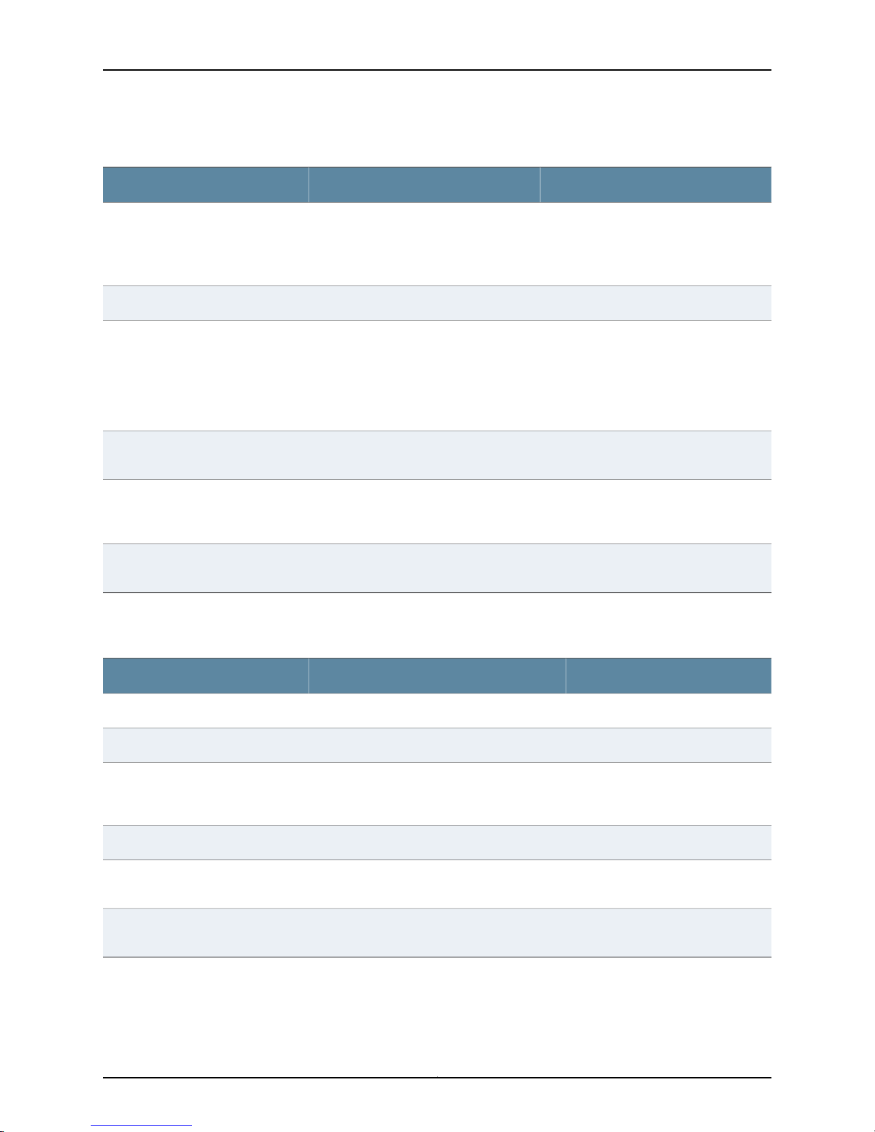
Figure 1 on page 5 shows the basic structure of application-level errors returned by the
NSM server. Table 4 on page 5 describes the frequently used ErrorType data type.
Copyright © 2010, Juniper Networks, Inc.4
Page 23
Figure 1: ErrorType Data Type
Chapter 1: Overview
Table 4: ErrorType Data Types
DescriptionData Type
ErrorType
These request errors (not infrastructure errors) are issued when the system encounters business data
problems (for example, an invalid combination of arguments). This complexType data has the following
sequence:
•
ErrorNumber = Unique number that identifies the particular error condition (type = unsignedInt). This
data element is only used by the server.
•
ErrorMessage = Brief description of the condition that raised the error (type = string).
•
ErrorActor = The source (location) of the error (type = string).
•
ErrorDetails = Detailed error message (type = string).
5Copyright © 2010, Juniper Networks, Inc.
Page 24

Network and Security Manager 2010.4 API Guide
Copyright © 2010, Juniper Networks, Inc.6
Page 25

CHAPTER 2
NSM API Operations
The application programminginterface(API) defined byNSM isused toprovision policies,
manage and monitor devices, and generate reports. The API has four parts:
•
System Service API on page 7
•
Data Centric Service API on page 8
•
Job Service API on page 11
•
Log Service API on page 13
System Service API
The API System Service processes log in, log out, and system information requests.Table
5 on page 7 summarizes the API data elements.
For information about the WSDL file defining the API, see “System Service API WSDL”
on page 129 .
Table 5: System Service API Operations
DescriptionOperation
LoginRequest
Log into NSM server.
Request:
•
domainName = Domain supplied during login. The user logs in to this domain.
NOTE: Use global.<subdomain name> to log in to a subdomain and global to log in to
a global domain.
•
userName = User name supplied during login.
•
password = Password supplied during login.
Response:
•
loginStatus = Uses LoginStatusCodeType to return:
“Success” if the login is successful.
“Failure” for login rejection.
“Challenge” if the login request is being challenged but not yet denied.
•
authToken =Token returned for login request success. This token is reused for other
requests during the current session.
7Copyright © 2010, Juniper Networks, Inc.
Page 26

Network and Security Manager 2010.4 API Guide
Table 5: System Service API Operations (continued)
RespondToChallengeRequest
LogoutRequest
GetSystemInfoRequest
Data Centric Service API
Reuses the token received in LoginResponse to send a response to the challenge.
Receives a token if the response is successful.
Request: Answer to the challenge question.
Response: Token received.
Logout from the system.
Request: none
Response: none
This operation retrieves system information (service list and all accessible domain IDs
and names).
Request: serviceName
Response: serviceDesc, domain name and domain ID.
NOTE: When using the LoginRequest API, enter global.<subdomain name>
to log in to a particular subdomain. The login fails if just the subdomain name
is used.
The Data Centric Service API provides access to the internal data of NSM. It receives
incoming data access requests, retrieves the data from NSM, conducts any necessary
transformations, and sends the transformed data back as responses. This section
introduces the XML subtree filter used with the service and describes the Data Centric
data elements.
NOTE: In the current release of NSM, write accessto the deviceobj and sysvpn
from the Data Centric Service is blocked to protect data integrity.
See “Data Centric API WSDL”on page 135 for a description of the API-definingWSDL file.
Data Centric Service XML Subtree Filter
The filter used in the Data Centric Service API is the XML subtree filter defined by
NETCONF. Subtree filtering is a mechanism that allows an application to select particular
XML subtrees from the configurations from the devices.
A subtree filter consists of zero or more element subtrees, which represent the filter
selection criteria.
Five types of components may be present in a subtree filter:
Copyright © 2010, Juniper Networks, Inc.8
Page 27

•
Namespace selection
•
Attribute matching expressions
•
Containment nodes
•
Selection nodes
•
Content matching nodes
Only the first four are supported in the NSM API.
Data Centric Service Operations
Table 6 on page 9 summarizes Data Centric Service operations.
Table 6: Data Centric API Operations
GetObjectDependentRequest
Chapter 2: NSM API Operations
DescriptionOperations
Gets objects that refer to the object specified in the request.
Request:
GetObjectViewByCategoryRequest
•
objectIdentifier= Identifies the object to be retrieved (type =
objectIdentifierType)
•
dbVersionId= Version of the database (type = unsignedInt)
•
objectFilter = Filter to be applied to the result (type = ObjectFilterType)
•
metadataOnly = Iftrue, only the metadata is returned. Otherwise, the entire
object is returned.
Response: object
Gets objects in one category.
Request:
•
category = Schema name of the category (type = string)
•
domainId = Domain of the schema (type = unsignedShort)
•
dbVersionId= Version of the database (type = unsignedInt)
•
objectFilter = Filter to be applied to the result (type = ObjectFilterType)
•
view =Transformationof theobject. Forthe default view, the returnedobject
follows the schema with no transformation (type = ViewType).
•
property = Transformation parameters (type = NameValueType).
Response: object
9Copyright © 2010, Juniper Networks, Inc.
Page 28

Network and Security Manager 2010.4 API Guide
Table 6: Data Centric API Operations (continued)
GetObjectViewByIdRequest
LockObjectRequest
UnlockObjectRequest
ModifyObjectViewRequest
Gets objects by ID.
Request:
•
objectIdentifier= Identifies the object to be retrieved (type =
objectIdentifierType)
•
dbVersionId= Version of the database (type = unsignedInt)
•
objectFilter = Filter to be applied to the result (type = ObjectFilterType)
•
view =Transformationof theobject. Forthe default view, the returnedobject
follows the schema with no transformation (type = ViewType).
•
property = Transformation parameters (type = NameValueType).
Response: object
Locks the specified object.
Request: objectIdentifier
Response: objectLockStatus
Unlocks the specified object.
Request: object
Response: objectLockStatus
Modifies the object. All commands in the request are executed in one
transaction. ModifyObjectViewRequest supports the following operations:
•
Update Node
•
Insert node before / after
•
Append node
•
Insert Object
•
Replace Object
•
Delete Object
NOTE: You should lockthe object before modifying itand unlock it afterwards.
The modification will fail if the object is locked by a different user session.
However, a modification request without prior locking can run if the object is
not locked by the others. Data corruption does not occur even if an API user
forgets to lock an object before modifying it.
Request:
•
command =Command that modifiesthe object (type = ModifyCommand).
Response:
•
metadata
•
objectModification
•
subObjectModification
Copyright © 2010, Juniper Networks, Inc.10
Page 29

Table 6: Data Centric API Operations (continued)
Chapter 2: NSM API Operations
QueryObjectViewRequest
ResolveObjectReferenceRequest
Queries the object.
Request:
•
category = Schema name of the category (type = string).
•
simpleQuery = Query expression (type = SimpleQueryType).
•
dbVersionId= Version of the database (type = unsignedInt)
•
objectFilter = Filter to be applied to the result (type = ObjectFilterType)
•
view =Transformationof theobject. Forthe default view, the returnedobject
follows the schema with no transformation (type = ViewType).
•
property = Transformation parameters (type = NameValueType).
Response:
•
queryId
•
object
Resolves the object reference.
Request:
•
objectReference = Object reference to be resolved (type = string)
•
dbVersionId= Version of the database (type = unsignedInt)
•
objectFilter = Filter to be applied to the result (type = ObjectFilterType)
Response: object
Job Service API
The Job Service API processes command directives to configure devices and display the
results. Table 7 on page 11 summarizes the API operations.
See “Job Service API WSDL” on page 121 for the Web Service Description Language
(WSDL) definition of the API.
Table 7: Job Service API Operations
UpdateDeviceRequest
DescriptionOperation
Request to update the device configuration.
Request: JobRequestType
•
jobName= Name of the job.
•
scheduleTime= Time when the job will run. If not specified, the job will
run immediately.
•
jobArgs= List of the devices to which the job applies (type =
JobArgsType).
Response: JobResponseType
•
status = Job status.
•
jobName = Name of the job.
•
response = Response to the job.
11Copyright © 2010, Juniper Networks, Inc.
Page 30

Network and Security Manager 2010.4 API Guide
Table 7: Job Service API Operations (continued)
DescriptionOperation
ImportDeviceRequest
GetConfigSummaryRequest
Request to import a device configuration from physical devices.
Request: JobRequestType
•
jobName= Name of the job.
•
scheduleTime= Time when the job will run. If not specified, the job will
run immediately.
•
jobArgs= List of the devices to which the job applies.
Response: JobResponseType
•
status = Job status.
•
jobName = Name of the job.
•
response = Response to the job.
Requestfor asummary ofthe configuration currently running ona physical
device.
Request: JobRequestType
•
jobName= Name of the job.
•
scheduleTime= Time when the job will run. If not specified, the job will
run immediately.
•
jobArgs= List of the devices to which the job applies.
Response: JobResponseType
•
status = Job status.
•
jobName = Name of the job.
•
response = Response to the job.
GetRunningConfigRequest
Request for the configuration currently running on a physical device.
Request: JobRequestType
•
jobName= Name of the job.
•
scheduleTime= Time when the job will run. If not specified, the job will
run immediately.
•
jobArgs= List of the devices to which the job applies.
Response: JobResponseType
•
status = Job status.
•
jobName = Name of the job.
•
response = Response to the job.
Copyright © 2010, Juniper Networks, Inc.12
Page 31

Table 7: Job Service API Operations (continued)
DescriptionOperation
Chapter 2: NSM API Operations
GetDeltaConfigRequest
GetJobStatusRequest
Request for the differences between the modeled device configuration
and the configuration currently running on a physical device.
Request: JobRequestType
•
jobName= Name of the job.
•
scheduleTime= Time when the job will run. If not specified, the job will
run immediately.
•
jobArgs= List of the devices to which the job applies.
Response: JobResponseType
•
status = Job status.
•
jobName = Name of the job.
•
response = Response to the job.
Request for the status of a job.
Request:
•
domainName = Name of the domain associated with the job.
•
domainId= ID of the domain.
•
jobName= Name of the job.
Response: JobResponseType
•
status = Job status.
•
jobName = Name of the job.
•
response = Response to the job.
GetJobResultRequest
Log Service API
Request for status of a completed job.
Request:
•
domainName = Name of the domain associated with the job.
•
domainId= ID of the domain.
•
jobName= Name of the job.
Response: JobResponseType
•
status = Job status.
•
jobName = Name of the job.
•
response = Response to the job.
The Log Service API retrieves and displays logs of NSM events. Table 8 on page 14
summarizes these operations.
See “Data Centric API WSDL” on page 135 for the WSDL file defining the API.
13Copyright © 2010, Juniper Networks, Inc.
Page 32

Network and Security Manager 2010.4 API Guide
Table 8: Log Service API Operations
GetPacketDataRequest
DescriptionOperation
Gets both the log data and the packet data that triggers the log.
Request:
•
dayId= Identifier for the day.
•
recordNum= Record number.
Response:
•
numPackets= Number of packets returned.
•
triggerPacket = Packet triggering the log event.
•
data = Log data.
Copyright © 2010, Juniper Networks, Inc.14
Page 33

PART 2
API Data Types
•
Data Objects on page 17
•
Common Message Data Types on page 21
•
Security Data Model on page 23
15Copyright © 2010, Juniper Networks, Inc.
Page 34

Network and Security Manager 2010.4 API Guide
Copyright © 2010, Juniper Networks, Inc.16
Page 35

CHAPTER 3
Data Objects
•
API Data Objects on page 17
API Data Objects
A data object is data that is identifiable by the NSM API. NSM data objects are logically
grouped by domains and categories. A domain is a logical grouping of devices, their
security policies, and their access privileges. A category is a logical grouping of the data
objects that have the same structure. For example, a deviceobj is a category of data
objects for devices.
Each object in a category is identified by a tuple (domain, category, object id). The XML
representation of the data objects conforms to the XML schemas illustrated later in this
chapter.
Objects are referenced by name or ID.
•
Reference based on id. The reference to an object is defined in the following format
&<domain id>.<category name>.<object id>. For example, &1.service.100.
•
Reference based on name. The reference to an object defined in the following format
&<domain id>.<category name>.?????????<object name>. Here, nine question marks
precede <object name>.
The key data types are illustrated in Figure 2 on page 18. The entire set of common data
types is described in Table 9 on page 18.
17Copyright © 2010, Juniper Networks, Inc.
Page 36

Network and Security Manager 2010.4 API Guide
Figure 2: NSM API Data Objects
Table 9: API Data Objects
DescriptionData Type
DataFormatType
OpaqueDataType
ObjectIdentifierType
This simpleType data code has the following possible enumeration values:
•
•
•
•
•
•
This complexType data code (base64Binary element) has one value:
•
This complexType data code has the following sequence:
•
•
•
“XML”
“NML”
“XML_FROM_NML”
“NML_AND_XML”
“JAVA_OBJECT”
“FILE”
attribute name = “dataFormat” (type = DataFormatType)
domainId = ID of the domain (type = unsignedShort)
category = Schema name of the category (type = string)
objectIdOrName = Object ID or name (type = ObjectIdOrNameType).
Copyright © 2010, Juniper Networks, Inc.18
Page 37

Table 9: API Data Objects (continued)
DescriptionData Type
Chapter 3: Data Objects
ObjectMetadataType
ObjectIdOrNameType
DomainIdOrNameType
SubObjectDataType
This complexType data code has the following sequence:
•
domainId = ID of the domain (type = unsignedShort)
•
category = Schema name of the category (type = string)
•
objectId = Object identifier (type = unsignedInt).
•
objectName = Name of the object (type = string).
•
objectVersionId = Identifier of the object version (type = unsignedInt).
•
lowDBVersionId= Lowest database version identifier (type = unsignedInt).
•
highDBVersionId= Highest database version identifier (type = unsignedInt).
This complexType data code takes only one of the following inputs:
•
objectId = Object identifier (type = unsignedInt).
or
•
objectName = Name of the object (type = string).
This complexType data code takes only one of the following inputs:
•
objectId = Object identifier (type = unsignedInt).
or
•
objectName = Name of the object (type = string).
This complexType data code has the following sequence:
•
subCategory = Subcategory under “category” (type = string).
•
data = Subobject data (type = OpaqueDataType).
ObjectDataType
ObjectType
StatusCodeType
AuthTokenType
SequenceType
This complexType data code has the following sequence:
•
objectName = Name of the object (type = string).
•
data = Object data (type = OpaqueDataType).
•
subObjectData = Data of the subobject (type = SubObjectDataType).
This complexType data code has the following sequence:
•
objectMetadata = Metadata object (type = ObjectMetadataType).
•
objectData = Object data (type = ObjectDataType).
This simpleType data code has the following possible enumeration values:
•
Success = Request is successful.
•
Failure = Request has failed.
This complexType data code is the security header for SOAP API calls. It has one value:
•
Token = String identifying the user (type = string).
This complexType data code is a partial response type. It has the following sequence:
•
SequenceNum= Sequence number of the current response (type = int).
•
IsDone = Total number of response messages (type = Boolean).
19Copyright © 2010, Juniper Networks, Inc.
Page 38

Network and Security Manager 2010.4 API Guide
Table 9: API Data Objects (continued)
DescriptionData Type
ProgressType
ConversationContextType
This complexType data code takes one input:
•
CompletionPercent = Percent completed of the response (type = unsignedInt).
This complexType data code has the following sequence:
•
ConversationId = Identifier for the message conversation (type = string).
•
UserSessionContext = Describes the context of the user session (type = anyType).
•
AuditLogContext = Context for the audit log (type = anyType).
•
ACFilter = Filter (type = anyType).
Copyright © 2010, Juniper Networks, Inc.20
Page 39

CHAPTER 4
Common Message Data Types
This chapter describes the message types, SimpleRequest and SimpleResponse, that
are most commonly used in API data messages.
•
SimpleRequestType and SimpleResponseType Data Types on page 21
SimpleRequestType and SimpleResponseType Data Types
The frequently used data types SimpleRequestType and SimpleResponseType are
illustrated in Figure 3 on page 21 and Figure 4 on page 21. They are described in Table
10 on page 22
Figure 3: SimpleRequestType Data Type
Figure 4: SimpleResponseType Data Type
21Copyright © 2010, Juniper Networks, Inc.
Page 40

Network and Security Manager 2010.4 API Guide
Table 10: SimpleRequestType and SimpleResponseType Definitions
DescriptionData Type
SimpleRequestType
SimpleResponseType
Base type definition of the SOAP body of the request.All request types are derived from theabstract
type. The naming convention for concrete type names is the name of the service (verb or call name)
followed by “RequestType.” Generally, VerbNameRequestType.
This complexType data has the following sequence:
•
ConversationContext = Context of the message conversation (type = ConversationContextType).
•
AuthToken = Token returned for the simple request (type = AuthTokenType).
Base type definition of the SOAP body of a response. This complexType data has the following
sequence:
•
Status = Status of the response (type = StatusCodeType).
•
ConversationContext = Context of the message conversation (type = ConversationContextType).
•
Errors = Errors returned (type = ErrorType).
Copyright © 2010, Juniper Networks, Inc.22
Page 41

CHAPTER 5
Security Data Model
This chapter introducesaspects of the APIdata modelthat apply to NSM security policies.
For complete details, see the dm.xsd and dm.xsd definition files included with the file set
in this release.
The adm.xsd is located at $NSROOT/GuiSvr/var/be/schemas/dmi-nsm/ . The smaller
zip file (adm.zip) is located at $NSROOT/GuiSvr/var/be/schemas/dmi-nsm/document.
This chapter contains the following sections:
•
NSM Policy on page 23
•
Security Rulebases on page 25
•
Service (service_collection) on page 54
•
Address (address_collection_type) on page 56
•
Schedule Object (scheduleobj_collection_type) on page 57
•
Attack (attack_collection) on page 58
•
Antivirus (avobj_collection) on page 62
•
GTP (gtpobj_collection_type) on page 64
•
DI Profile (DIProfile_collection_type) on page 67
•
Global DIP (globaldip_collection) on page 67
•
Global MIP (globalmpi_collection) on page 68
•
Global VIP (globalvip_collection) on page 69
•
URL Filter Object (urlfilter_collection) on page 70
NSM Policy
The NSM Policy collection (nsmpolicy_collection) data elements are illustrated and
described in Figure 5 on page 24 and Table 11 on page 24.
23Copyright © 2010, Juniper Networks, Inc.
Page 42

Network and Security Manager 2010.4 API Guide
Figure 5: NSM Policy
Table 11: NSM Policy Data Elements
DescriptionData Element
Name of the security policy (string).name_
Comments about the security policy.comment
accesstype
firewall
Type of access. (enum) Possible values are:
•
regular = regular policy
•
pre = domain pre policy
•
post = domain post policy
•
mompre = central manager pre policy
•
mompost = central manager post policy
(Optional) Effective start date for the NSM security policy.createFrom
Collection of references of rulebases. For more information, see “Security Rulebases” on page 25.rulebases
Reference of the firewall rulebase. Firewall rule data elements are included in a security policy. For
more information, see “Firewall (rb_firewall_collection)” on page 33.
Copyright © 2010, Juniper Networks, Inc.24
Page 43

Table 11: NSM Policy Data Elements (continued)
DescriptionData Element
Chapter 5: Security Data Model
multicast
idp
exempt
backdoor
portfaker
syndef
tsig
Security Rulebases
Reference of the multicast rulebase. Multicast rule data elements are included in a security policy.
For more information, see “Multicast (rb_multicast_collection)” on page 43.
Reference of the IDP rulebase, Idp rule data elements are included in a security policy. For more
information, see “IDP (rb_idp_collection)” on page 39.
Reference of the Exempt rulebase. Exempt rule data elements are included in a security policy. For
more information, see “Exempt (rb_exempt_collection)” on page 30.
Reference of the backdoor rulebase. Backdoor rule data elements are included in a security policy.
For more information, see “Backdoor (rb_backdoor_collection)” on page 25.
Network Honeypot (portfaker) rulebase. These data elements are included in a security policy. For
more information, see “Traffic Anomalies (rb_tsig_collection)” on page 48.
Reference of the SYN Protector rulebase, These data elements are included in a security policy. For
more information, see “SYN Protector (rb_syndef_collection)” on page 45.
Traffic Anomalies rulebase. These data elements are included in a security policy. For more
information, see “Traffic Anomalies (rb_tsig_collection)” on page 48.
NSM security policies are configured by applying rules that are grouped into rulebases.
Each rulebase can contain one or more rules, which are statements that define specific
types ofnetwork traffic. Whentraffic passes througha securitydevice, the deviceattempts
to match that traffic against its list of rules. If a rule is matched, the device performs the
action defined in the rule against the matching traffic. Zone rules enable traffic to flow
betweenzones (interzone) orbetweentwo interfacesbound tothe samezone (intrazone).
Global rules are valid across all zones available on the device. Security devices process
rules in the zone-specific rulebase first, and then rules in the global rulebase.
The NSM API data model supports the security policy rulebases summarized in the
following sections.
Backdoor (rb_backdoor_collection)
The backdoor rulebase collection (rb_backdoor_collection) contains rules that enable
NSM to detect attempted backdoor intrusions. A backdoor is a mechanism installed on
a host computer that enables unauthorized access to the system. Attackers who have
already compromised a system can install a backdoor to make future attacks easier.
When attackers type commands to control a backdoor, they generate interactive traffic.
Unlike antivirus software, which scans for known backdoor files or executables on the
host system, IDP detects the interactive traffic that is produced when backdoors are
used. If interactive traffic is detected, IDP can perform IP actions against the connection
to prevent the attacker from further compromising your network.
25Copyright © 2010, Juniper Networks, Inc.
Page 44

Network and Security Manager 2010.4 API Guide
When you configure a backdoor rule, you must specify the following:
•
Source and destination addresses for traffic that will be monitored
•
Services that are offered by the source or destination and any interactive services that
can be installed and used by attackers
For configuration procedures, see the NSM Online Help and the NSM Administrator's
Guide.
The data elements in the backdoor rulebase are illustrated and described in Figure 6 on
page 27 and Table 12 on page 27.
Copyright © 2010, Juniper Networks, Inc.26
Page 45

Figure 6: Backdoor Rulebase
Chapter 5: Security Data Model
Table 12: Backdoor Rulebase Data Elements
DescriptionData Element
Name of the backdoor rule type. (string).name_
Collection of all sets of rules.rules_collection
Collection of all rules.rules
27Copyright © 2010, Juniper Networks, Inc.
Page 46

Network and Security Manager 2010.4 API Guide
Table 12: Backdoor Rulebase Data Elements (continued)
DescriptionData Element
Rule number.ruleno
preferred-id
A rule ID is a number that uniquely identifies a rule within the
rulebase and security policy. After you install a rule as part of
a security policy on a security device, you can view the rule by
logging in locally to the device. However, when you view it
through the Web UI or CLI, the rule appears as an individual
policy. The individual policy on the device has the same ID as
the rule in themanagement system,enabling you to determine
which rules are on specific devices.
Comments about the backdoor rules.comments
Rule group name.rb-link
Custom options.customOptions_collection
Collection enabled.enabled
The source sends traffic from this zone.src_zone_collection
Address of the traffic source.src_addr_collection
Negates the specified source address.src_addr_negate
The source sends traffic to this zone.dst_zone_collection
Destination address for the traffic.dst_addr_collection
service
Negates the specified destination address.dst_addr_negate
These service object rules specify the service that an attack
uses to access the network.
Copyright © 2010, Juniper Networks, Inc.28
Page 47

Table 12: Backdoor Rulebase Data Elements (continued)
DescriptionData Element
Chapter 5: Security Data Model
action
op
log
For each attack that matches a rule, you can choose an action
that will occur if the IDP detects interactive traffic. The
following actions are possible:
•
Accept = IDP accepts the interactive traffic
•
Drop Connection = IDP drops the interactive connection
without sending an RST packet to the sender. This prevents
the traffic from reaching its destination. This action is
selected to drop connections from traffic that is not prone
to spoofing.
•
Close Client = IDP closes the interactive connection to the
client but not to the server.
•
Close Server = IDP closes the interactive connection to the
server but not to the client.
•
Close Client and Server = IDP closes the interactive
connection and sends a RST packet to both the client and
the server. If IDPis operating in an inline tap mode, IDP sends
a RST packet to both the client and the server but does not
close the connection.
Sets the operation to detect or ignore. If you select detect,
choose an action to perform if backdoor traffic is detected.
If this parameter is enabled, the API logs an attack and creates
log records with attack information. You can display this
information real time in the Log Viewer. For more critical
attacks, you can set an alert flag that will appear in the log
record.
vlan
log-actions
This parameter configures a rule that only appliesto messages
in specified VLANs. The possible settings are:
•
Any (default) = Any rule will be applied to messages in any
VLAN andto messages without a VLAN tag. This settinghas
the same effect as not specifying a VLAN. Any can be sent
to devices that do not support VLAN tagging.
•
None = A rule will be applied only to messages that do not
have a VLAN tag. Rules with this value set cannot be sent
to devices that do not support VLAN tagging.
•
vlan_list_collection = Specifies the VLAN tags to which the
rule applies. You must create VLAN objects before applying
them to the rules. Rules with this value set cannot be sent
to devices that do not support VLAN tagging.
Action to be taken on the log. This can include configuring
SNMP, Syslog, CSV, XML, script, and e-mail settings.
29Copyright © 2010, Juniper Networks, Inc.
Page 48

Network and Security Manager 2010.4 API Guide
Table 12: Backdoor Rulebase Data Elements (continued)
severity
target_collection
Exempt (rb_exempt_collection)
The exempt (rb_exempt_collection) rulebase works in conjunction with the IDP rulebase.
Before you create exempt rules, you must create rules in the IDP rulebase. If traffic
matches a rule in the IDP rulebase, IDP attempts to match the traffic against the rules
in the exempt rulebase before performing the specified action or creating a log record
for the event. When the IDP rulebase is deleted, the exempt rulebase is automatically
deleted. When you create an exempt rule, you must specify the source and destination
traffic to be exempted and the specific attacks that IDP will exempt.
Severityof the attack. Within the IDP rulebase, you can override
the ordinary attack severity on a per-rule basis. Possible
settings:
•
Default
•
Info
•
Warning
•
Minor
•
Major
•
Critical
Log packets.seslog
Specifies the security devices or templates that will receive
and use this rule. You can select multiple security devices on
which to install the rule.
The data elements in the exempt rulebase are illustrated and described in Figure 7 on
page 31 and Table 13 on page 31.
Copyright © 2010, Juniper Networks, Inc.30
Page 49

Figure 7: Exempt Rulebase
Chapter 5: Security Data Model
Table 13: Exempt Rulebase Data Elements
DescriptionData Element
Name of the exempt type.name_
Collection of all sets of rules.rules_collection
Collection of all rules.rules
Row count per rule in the collection.rowcountperrule_collection
Next preferred ID.next_preferred_id
31Copyright © 2010, Juniper Networks, Inc.
Page 50

Network and Security Manager 2010.4 API Guide
Table 13: Exempt Rulebase Data Elements (continued)
DescriptionData Element
Rule number.ruleno
Comments about the exempt collection.comments
Custom options.customOptions_collection
Collection enabled.enabled
preferred-id
attacks
A rule ID is a number that uniquely identifies a rule within the rulebase and security policy.
After you install a rule as part of a security policy on a security device, you can view the rule
by logging in locally to the device. However, when you view it through the Web UI or CLI,
the rule appears as an individual policy. The individual policy on the device has the same
ID as the rule in the management system, enabling you to determine which rules are on
specific devices.
Rule group name.rb-link
The source sends traffic from this zone.src_zone_collection
Address of the traffic source.src_addr_collection
Negates the specified source address.src_addr_negate
The source sends traffic to this zone.dst_zone_collection
Destination address for the traffic.dst_addr_collection
Negates the specified destination address.dst_addr_negate
Exempt type service.service
The attacks that IDP will exempt for the specified source/destination address. You must
include at least one attach object in an exempt rule.
vlan
target_collection
This parameter configures a rule that only applies to messages in specified VLANs. The
possible settings are:
•
Any (default) = Any rule will be applied to messages in any VLAN and to messages
without a VLAN tag. This setting has the same effect as not specifying a VLAN. Any can
be sent to devices that do not support VLAN tagging.
•
None = A rule will be applied only to messages that do not have a VLAN tag. Rules with
this value set cannot be sent to devices that do not support VLAN tagging.
•
vlan_list_collection = Specifiesthe VLAN tags to which the rule applies. You must create
VLAN objects before applying them to the rules. Rules with this value set cannot be sent
to devices that do not support VLAN tagging.
Specifies thesecurity devices or templates that will receive and use this rule. You can select
multiple security devices on which to install the rule.
Copyright © 2010, Juniper Networks, Inc.32
Page 51

Firewall (rb_firewall_collection)
The firewall (rb_firewall_collection) rulebase contains zone-specific and global rules. A
security policy can contain two firewall rulebases: zone-specific and global.
The data elements in the firewall rulebase are illustrated and described in Figure 8 on
page 33, Figure 9 on page 34, and Table 14 on page 35.
Figure 8: Firewall Rulebase
Chapter 5: Security Data Model
33Copyright © 2010, Juniper Networks, Inc.
Page 52

Network and Security Manager 2010.4 API Guide
Figure 9: Firewall policy_type
Copyright © 2010, Juniper Networks, Inc.34
Page 53

Table 14: Firewall Data Elements
DescriptionData Element
Name of the policy type.name_
Collection of all sets of rules.rules_collection
Row count per rule in the collection.rowcountperrule_collection
Next preferred ID.next_preferred_id
Rule title.pol_name
Custom options.customOptions_collection
Comments about the firewall collection.comments
Collection enabled.enabled
Chapter 5: Security Data Model
service_collection
action
Rule group ID. (string)group_address
Rule group name.rb-link
VPN link associated with the policy type.vpnlink
Policy direction.direction
RAS VPN.dialupvpn
Address of the traffic source.src_addr_collection
Negates the specified source.negate_src
All VIPs. (Boolean)dst-all-vip
Destination address for the traffic.dst_addr_collection
Negates the specified destination.negate_dst
Configure theservices supported by the destination. If the service ofthe network traffic matches
a service selected inthe rule, the security device performs the actionthat you select in theAction
column. For more information, see “Service (service_collection)” on page 54.
Determinesthe actionto be performed by thesecurity devicewhen itdetects traffic that matches
the rule. The possible values are:
•
deny
•
permit
•
reject
•
tunnel
35Copyright © 2010, Juniper Networks, Inc.
Page 54

Network and Security Manager 2010.4 API Guide
Table 14: Firewall Data Elements (continued)
DescriptionData Element
Source NAT.nat-dip
nat
preferred-id
count
log-actions
target_collection
You can configure your security device to perform policy level network address translation (NAT)
for any zone to translate the source address of incoming and outgoing traffic. You can configure
the firewall to select a new source address from a Dynamic IP pool (DIP). For incoming traffic
only, use a Mapped IP (MIP).
A preferred-id is a rule ID,a number that uniquelyidentifies a rule within the rulebaseand security
policy. After you install a rule as part of a security policy on a security device, you can view the
rule by logging in locally to the device. However, when you view it through the Web UI or CLI, the
rule appears as an individual policy. The individual policy on the device has the same ID as the
rule in the management system, enabling you to determine which rules are on specific devices.
Deep inspection alert log.log
Select Counting if you want to count how many bytes the matching network traffic contains and
view this information in other applications. Possible values:
•
disabled
•
enabled
Action to be taken on the log. This can include configuring SNMP, Syslog, CSV, XML, script, and
e-mail settings.
Web filtering. (default = false)url-blk
URL protocol.url-protocol
Specifies the security devices or templates that will receive and use this rule. You can select
multiple security devices on which to install the rule.
Copyright © 2010, Juniper Networks, Inc.36
Page 55

Table 14: Firewall Data Elements (continued)
DescriptionData Element
Chapter 5: Security Data Model
auths
schedule
You must include HTTP, FTP, or Telnet service objects in the Service column of the rule to enable
remote users to authenticate themselves using Authentication. You can include other services
as well, or specify all services.
If authentication succeeds, the NSM allows the remote user to establish a connection to the
destination address. If authentication fails, NSM drops the initial connection.
If the source address supports multiple remote user accounts (for example, a Unix host running
Telnet) or it is located behind a NAT device thatuses a single IP address for all NAT assignments,
only the first remote user from that source address must initiate andauthenticate anHTTP, FTP,
or Telnet connection. All subsequent remote users from that source address do not have to
authenticate, and can pass matching network traffic to the destination address.
If you useWebAuth, to make a connectionto the destination address in the rule, the remote user
must first initiate an HTTP connection to the WebAuth server. Your security device responds
with a login prompt. After the remote user provides a user name and password, NSM attempts
to authenticate the user credentials. If authentication succeeds, NSM permits the remote user
to establisha connection to the destination address. If authentication fails, NSM drops the initial
connection. The possible values:
•
no-auth
•
infranet-auth
•
auth
•
webauth
You can determine when a security device applies a rule tonetwork traffic bydefining a schedule
for the rule.
ha_session_backup
traffic
If youselect HA Session Backup, a rule with the Permitaction willnot be active whenthe session
switches to the modern link. When this happens, the rule takes the Deny action.
Disable modem idle timer reset. (default = false)no-idle-reset
Traffic shaping enables you to control the amount of bandwidththat isavailableto thematching
network traffic in a rule. It also enables you to set a priority that determines how the security
device handles matching network traffic that exceeds the defined maximum bandwidth. For
security devices running ScreenOS 5.3 or later, you can also manage the flow of traffic through
the security device by limiting bandwidth at the incoming point. The possible values:
•
gbw
•
priority
•
mbw
37Copyright © 2010, Juniper Networks, Inc.
Page 56

Network and Security Manager 2010.4 API Guide
Table 14: Firewall Data Elements (continued)
DescriptionData Element
application
Application.
NOTE: You can override a service that is set in the Service column at the application layer. The
service set in the Service column remains in force for the transport layer.
Possible enumeration values:
•
DNS
•
FTP
•
HTTP
•
IMAP
•
SMTP
•
POP3
•
H245
•
Q931
•
RAS
•
PORTMAPPER
•
SIP
•
SQLNETV2
•
TALK
•
TFTP
•
REAL
•
RTSP
•
VDO
•
XING
•
IGNORE
•
MGCP_CA
•
MGCP_UA
•
PPTP
•
RSH
•
SCCP
•
AIM
•
YMSG
•
SMB
•
MSN
•
NBNAME
•
NBDS
•
NAS
•
NONE = No application specified. (default)
attack-policy
Security devices running ScreenOS 5.3 or later support Deep Inspection. A Deep Inspection (DI)
Profile object contains predefined attack object groups (created by Juniper Networks) or your
own custom attack object groups.
idp
Intrusion Detection and Prevention (IDP) is only supported on devices that have an IDP license
installed. When you install a IDP license, DI is disabled on the device.
Copyright © 2010, Juniper Networks, Inc.38
Page 57

Table 14: Firewall Data Elements (continued)
DescriptionData Element
Chapter 5: Security Data Model
application-services
gtp
av
IDP (rb_idp_collection)
Application services. Possible values:
•
None (default)
•
RWX
•
RRWX
You can use a GTP object in a firewall rule to determine how your security devices handles GTP
traffic
To detect viruses in network traffic, you can configure the rule to forward traffic to an antivirus
scanner. The server or Scan Manager returns the traffic—after it is cleaned or altered—and the
security device executes the action specified in the Action column.
Antispam.anti-spam
The IDP (rb_idp_collection) rulebase includes IDP rules that protect your network from
attacks by using attack objects to identify malicious activity and take action. When you
create an IDP rule, you specify the type of network traffic to be monitored for attacks
including the from and to zone, source IP and destination IP for the network traffic, and
service (type of IP traffic associated with the application layer protocols supported at
the destination IP address). In security policies, service objects define the type of traffic
that a rule must monitor.
These data elements are illustrated and described in Figure 10 on page 40 and Table 15
on page 41.
39Copyright © 2010, Juniper Networks, Inc.
Page 58

Network and Security Manager 2010.4 API Guide
Figure 10: IDP Rulebase
Copyright © 2010, Juniper Networks, Inc.40
Page 59

Table 15: IDP Rulebase Data Elements
DescriptionData Element
Name of the IDP collection.name_
Collection of all sets of rules.rules_collection
Row count per rule in the collection.rowcountperrule_collection
Next preferred ID.next_preferred_id
Rule number.ruleno
Comments about the IDP collection.comments
Custom options.customOptions_collection
Collection enabled.enabled
Chapter 5: Security Data Model
preferred-id
terminal
A rule ID is a number that uniquely identifies a rule within the rulebase and security policy. After
you install a rule as part of a security policy on a security device, you can view the rule by logging
in locally to the device. However, when you view it through the Web UI or CLI, the rule appears
as an individual policy. The individual policy on the device has the same ID as the rule in the
management system, enabling you to determine which rules are on specific devices.
Rule group name.rb-link
The source sends traffic from this zone.src_zone_collection
Address of the traffic source.src_addr_collection
Negates the specified source address.src_addr_negate
The source sends traffic to this zone.dst_zone_collection
Destination address for the traffic.dst_addr_collection
Negates the specified destination address.dst_addr_negate
Application layer protocols that are supported by the destination IP address.service
Makes a rule terminal. Traffic matching the source, destination, and service of a terminal rule is
not compared to subsequent rules even if the traffic does not match an attack object in the
terminal rule.
41Copyright © 2010, Juniper Networks, Inc.
Page 60

Network and Security Manager 2010.4 API Guide
Table 15: IDP Rulebase Data Elements (continued)
DescriptionData Element
action
attacks
ipaction
vlan
For each attack that matches a rule, you can choose an action that will occur if the IDP detects
interactive traffic. The following actions are possible:
•
Accept = IDP accepts the interactive traffic
•
Drop Connection = IDP drops the interactive connection without sending a RST packet reset
flag) to the sender. This prevents thetraffic from reaching itsdestination. This action is selected
to drop connections from traffic that is not prone to spoofing.
•
Close Client = IDP closes the interactive connection to the client but not to the server.
•
Close Server = IDP closes the interactive connection to the server but not to the client.
•
Close Client and Server = IDP closes the interactive connection and sends a RST packet to
both the client and theserver.If IDP isoperating in an inlinetap mode, IDP sends aRST packet
to both the client and the server but does not close the connection.
DiffServ Marking.diffserv
Attack objects represent specific patterns of malicious activity within a connection. They also
specify a method for detecting attacks.
Enables andconfigures an IP action to preventfuture malicious connections from the attacker's
IP address.
Deep inspection alert loglog
This parameter configures a rule thatonly applies to messages in specified VLANs. The possible
settings are:
•
Any (default) = Any rule will be applied to messages in any VLAN and to messages without
a VLAN tag. This setting has the same effect as not specifying a VLAN. Any can be sent to
devices that do not support VLAN tagging.
•
None = A rule will be applied only to messages that do not have a VLAN tag. Rules with this
value set cannot be sent to devices that do not support VLAN tagging.
•
vlan_list_collection =Specifies theVLAN tags to which the ruleapplies. You mustcreateVLAN
objects before applying them to the rules. Rules with this value set cannot be sent to devices
that do not support VLAN tagging.
log-actions
Action to be taken on the log. This can include configuring SNMP, Syslog, CSV, XML, script, and
e-mail settings.
severity
Severity of the attack. Within the IDP rulebase, you can override the ordinary attack severity on
a per-rule basis. Possible settings:
•
Default
•
Info
•
Warning
•
Minor
•
Major
•
Critical
Log packets.seslog
Copyright © 2010, Juniper Networks, Inc.42
Page 61

Table 15: IDP Rulebase Data Elements (continued)
DescriptionData Element
Chapter 5: Security Data Model
target_collection
Specifies the security devices or templates that will receive and use this rule. You can select
multiple security devices on which to install the rule.
Multicast (rb_multicast_collection)
The multicast (rb_multicast_collection) rulebaseincludes multicast rules. Multicast rules
are statements that define specific types of multicast control traffic. When multicast
control traffic passes through a security device, the device attempts to match that traffic
against its list of rules. If a rule is matched, the device performs the action defined in the
rule against the matching traffic.
By default, security devices do not permit multicast control traffic (such as IGMP and
PIM-SM messages) to cross security devices. However, you can secure device multicast
control traffic through access lists. You can create an access listthat definesthe multicast
groups that hosts can join or to restrict the sources from which traffic is received, then
reference these access lists in multicast rules. To enable multicast control traffic to pass
between zones, you must configure multicast rules that specify the source zone (that
sends out multicast traffic), multicast group sending out the traffic, destination zone for
the traffic, and optionally, the destination group (source multicast group mapped to
another multicast group address).
These data elements are illustrated and described in Figure 11 on page 44 and Table 16
on page 44.
43Copyright © 2010, Juniper Networks, Inc.
Page 62

Network and Security Manager 2010.4 API Guide
Figure 11: Multicast Rulebase
Table 16: Multicast Rulebase Data Elements
from_zone
DescriptionData Element
Multicast rules.rb_multicast
Rules (string). Name of the rulebase collection.name_
Collection of all sets of rules.rules_collection
Collection of row count per rules.rowcountperrule_collection
Marks the start point for the zone in which to use the device.useDeviceZoneFrom
Marks the end point for the zone in which to use the device.useDeviceZoneTo
You must select asingle zonefor the source zone. Thesource will send multicast traffic
from this zone.
Copyright © 2010, Juniper Networks, Inc.44
Page 63

Table 16: Multicast Rulebase Data Elements (continued)
DescriptionData Element
From_zone exceptions.from_zone_exceptions
Chapter 5: Security Data Model
src-group
dst-group
target_collection
Multicast group(s) to which the multicast traffic is sent.
Multicast policy rules define the flow of multicast traffic between the source and
multicastgroups. You canuse thisparameterto specifyone particular multicast group,
any multicast group, or an access list that identifies the allowed multicast groups.
Destination zone. The source will send multicast traffic to this zone.to_zone
To_zone exceptions.to_zone_exceptions_collection
Destination group. Optionally, you can map the source multicast group address to
another multicast group address. When the source sends the multicast traffic to a
multicast group address, the security device translates the original multicast group
address to another address that you specified.
The rule applies to this type of multicast control traffic.message_type
Bi-directional policy.bi-directional
Custom options.customOptions_collection
Comment about the multicast collection.comments
Rule group name.rb-link
Specifies the security devices or templates that will receive and use this rule. You can
select multiple security devices on which to install the rule.
SYN Protector (rb_syndef_collection)
The SYN Protector (rb_syndef_collection) rulebase protects your network from
SYN-floods by ensuring that a three-way handshake is performed successfully for
specified TCP traffic. If you know that your network is vulnerable to a SYN-flood, use the
SYN-Protector rulebase to prevent it.
These data elements are illustrated and described in Figure 12 on page 46 and Table 17
on page 46.
45Copyright © 2010, Juniper Networks, Inc.
Page 64

Network and Security Manager 2010.4 API Guide
Figure 12: SYN Protector Rulebase
Table 17: SYN Protector Rulebase Data Elements
DescriptionData Element
SYN Protector rules.rb_syndef
Name of SYN Protector rule.name_
Collection of all sets of rules.rules_collection
Row count per rule in the collection.rowcountperrule_collection
Collection of all rules.rules
Rule number.ruleno
Copyright © 2010, Juniper Networks, Inc.46
Page 65

Table 17: SYN Protector Rulebase Data Elements (continued)
DescriptionData Element
Comments about the SYN Protector collection.comments
Custom options.customOptions_collection
Collection enabled.enabled
Traffic source address.src_addr_collection
Negates the specified source address.src_addr_negate
Traffic destination address.dst_addr_coillection
Negates the specified destination address.dst_addr_negate
Chapter 5: Security Data Model
service
mode
severity
log
vlan
The default service, TCP-any, looks for SYN floods in all TCP-based traffic.
NOTE: Always set the SYN Protector service value to TCP-any. Selecting individual services
can cause unpredictable interactions with other rulebases.
Select the mode that indicates how IDP handles TCP traffic. The possible values are:
•
None = no action taken.
•
Relay = IDP acts as the middleman or relay for the established connection.
•
Passive = IDP handles the transfer of packets between the client host and the server but
does not prevent the connection from being established.
Severity of the attack. Within the IDP rulebase, you can override the ordinary attack severity
on a per-rule basis. Possible settings:
•
Default
•
Info
•
Warning
•
Minor
•
Major
•
Critical
You can configure the system to log an attack and create log records with attack information.
This logged information can be viewed in real-time through the Log Viewer.
This parameter configuresa rulethat only appliesto messages in specifiedVLANs. Thepossible
settings are:
•
Any (default) = Any rule will be applied to messages in any VLAN and to messages without
a VLAN tag. This setting has the same effect as not specifying a VLAN. Any can be sent to
devices that do not support VLAN tagging.
•
None = A rule will be applied only to messages that do not have a VLAN tag. Rules with this
value set cannot be sent to devices that do not support VLAN tagging.
•
vlan_list_collection = Specifies the VLAN tags to which the rule applies. You must create
VLAN objects before applying them to the rules. Rules with this value set cannot be sent to
devices that do not support VLAN tagging.
47Copyright © 2010, Juniper Networks, Inc.
Page 66

Network and Security Manager 2010.4 API Guide
Table 17: SYN Protector Rulebase Data Elements (continued)
DescriptionData Element
log-actions
target_collection
Action to be taken on the log. This can include configuring SNMP, Syslog, CSV, XML, script,
and e-mail settings.
Specifies the security devices or templates that will receive and use this rule. You can select
multiple security devices on which to install the rule.
Traffic Anomalies (rb_tsig_collection)
The traffic anomalies (rb_tsig_collection) rulebase protect your network from attacks
by using traffic flow analysis to identify attacks that occur over multiple connections and
sessions (such as scans).
These data elements are illustrated and described in Figure 13 on page 49 and Table 18
on page 49.
Copyright © 2010, Juniper Networks, Inc.48
Page 67

Figure 13: Traffic Anomalies Rulebase
Chapter 5: Security Data Model
Table 18: Traffic Anamolies Rulebase Date Elements
DescriptionData Element
Traffic anomalies rules.rb_tsig
Name of the traffic rule collection.name_
Collection of all sets of rules.rules_collection
Row count per rule in the collection.rowcountperrule_collection
49Copyright © 2010, Juniper Networks, Inc.
Page 68

Network and Security Manager 2010.4 API Guide
Table 18: Traffic Anamolies Rulebase Date Elements (continued)
DescriptionData Element
Rule number.ruleno
Comments about the traffic anomalies collection.comments
Rule group name.rb-link
Custom options.customOptions_collection
Collection enabled.enabled
Address of the traffic source.src_addr_collection
Negates the specified source address.src_addr_negate
Destination address for the traffic.dst_addr_collection
traffic
Negates the specified destination address.dst_addr_negate
Serviceservice
Specifies how IDP will treat matching traffic. Possible values:
•
Ignore = The IDP Sensor ignores the traffic.
•
Detect = The IDP Sensor detects the traffic but does not log it.
•
TCP and UDP Port Scans = The IDP Sensor logs a TCP or UDP Port Scan, recording the TCP
or UDP ports and a time interval during which the IDP Sensor records count of that number
of TCP or UDP ports. For example, assume that the Port Count is 4 and the Time Threshold
is 2 seconds. If the IDP Sensor monitors 4 TCP or UDP ports over 2 seconds from the same
source IP to the same destination IP, the IDP Sensor logs it as a TCP or UDP port scan.
•
Distributed Port Scan = The IDP Sensor logs a Distributed Port Scan, recording the count of
unique IP addresses and a time interval during which the IDP Sensor records count of that
number of number of distributed addresses or ports. For example, the IP Count is 4 and the
Time Threshold is 2 seconds. If the IDP Sensor monitors 4 IP addresses over 2 seconds from
the same source IP to the same destination IP, the IDP Sensor logs it as a distributed port
scan.
•
ICMP Sweep =The IDPSensor logsan ICMP Sweep, recording the count ofunique IPaddresses
and a time interval during which the IDP Sensor records count of that number of IP addresses.
For example, the IP Count is 4 and the Time Threshold is 2 seconds. If the IDP Sensor monitors
4 IP addresses over 2 seconds from the same source IP, the IDP Sensor logs it as an ICMP
sweep.
•
Network Scan = The IDP Sensor logs a Network Scan, recording the count of unique IP
addresses and a time interval during which the IDP Sensor records count of that number of
IP addresses. For example, the IP Count is 4 and the Time Threshold is 2 seconds. If the IDP
Sensor monitors 4 IP addresses over 2 seconds from the same source IP, the IDP Sensor logs
it as a network scan.
ipaction
Enables and configures an IP action to prevent future malicious connections from the attacker's
IP address.
GTP logging.log
Copyright © 2010, Juniper Networks, Inc.50
Page 69

Table 18: Traffic Anamolies Rulebase Date Elements (continued)
DescriptionData Element
Chapter 5: Security Data Model
log-actions
vlan
severity
Log action settings. Possible settings include configuring:
•
SNMP
•
Syslog
•
CVS
•
XML
•
script
•
e-mail
This parameter configures a rule that only applies to messages in specified VLANs. The possible
settings are:
•
Any (default) = Any rule will be applied to messages in any VLAN and to messages without
a VLAN tag. This setting has the same effect as not specifying a VLAN. Any can be sent to
devices that do not support VLAN tagging.
•
None = A rule will be applied only to messages that do not have a VLAN tag. Rules with this
value set cannot be sent to devices that do not support VLAN tagging.
•
vlan_list_collection = Specifies the VLAN tags to which therule applies.You must create VLAN
objects before applying them to the rules. Rules with this value set cannot be sent to devices
that do not support VLAN tagging.
Severity of the attack. Within the IDP rulebase, you can override the ordinary attack severity on
a per-rule basis. Possible settings:
•
Default
•
Info
•
Warning
•
Minor
•
Major
•
Critical
target_collection
Specifies the security devices or templates that will receive and use this rule. You can select
multiple security devices on which to install the rule.
Network Honeypot (rb_portfaker_collection)
The network honeypot rulebase (rb_portfaker_collection) protects your network by
impersonating open ports on existing servers on your networkand alertingyou to attackers
performing port scans and other information-gathering activities.
These data elements are illustrated and described in Figure 14 on page 52 and Table 19
on page 52.
51Copyright © 2010, Juniper Networks, Inc.
Page 70

Network and Security Manager 2010.4 API Guide
Figure 14: Network Honeypot Rulebase
Table 19: Network Honeypot Rulebase Data Elements
DescriptionData Element
Network honeypot (portfaker) rules.rb_portfaker
Name of the portfaker type.name_
Collection of all sets of rules.rules_collection
Row count per rule in the collection.rowcountperrule_collection
Collection of all rules.rules
Copyright © 2010, Juniper Networks, Inc.52
Page 71

Table 19: Network Honeypot Rulebase Data Elements (continued)
DescriptionData Element
Rule numberruleno
Comments about the network honeypot (portfaker) collection.comments
Collection enabled.enabled
Portfaker Link collectionrb_link
Custom options.customOptions_collection
Address of the traffic source.src_addr_collection
Negates the specified source address.src_addr_negate
Destination address for the traffic.dst_addr_collection
Chapter 5: Security Data Model
ipaction
log-actions
vlan
Negates the specified destination address.dst_addr_negate
Serviceservice
Operationop
Enables and configures an IP action to prevent future malicious connections from the
attacker's IP address.
Logginglog
Action to be taken on the log. This can include configuring SNMP, Syslog, CSV, XML, script,
and e-mail settings.
This parameter configures a rule that only applies to messages in specified VLANs. The
possible settings are:
•
Any (default) = Any rule will be applied to messages in any VLAN and to messages
without a VLAN tag. This setting has the same effect as not specifying a VLAN. Any can
be sent to devices that do not support VLAN tagging.
•
None = A rule will be applied only to messages that do not have a VLAN tag. Rules with
this value set cannot be sent to devices that do not support VLAN tagging.
•
vlan_list_collection = Specifies the VLANtags to which the rule applies. Youmust create
VLAN objectsbefore applying them to the rules. Rules withthis valueset cannot be sent
to devices that do not support VLAN tagging.
53Copyright © 2010, Juniper Networks, Inc.
Page 72

Network and Security Manager 2010.4 API Guide
Table 19: Network Honeypot Rulebase Data Elements (continued)
DescriptionData Element
severity
target_collection
Severityof theattack. Within theIDP rulebase, you canoverride the ordinaryattack severity
on a per-rule basis. Possible settings:
•
•
•
•
•
•
Log packets.seslog
Specifies the security devices or templates that will receive and use this rule. You can
select multiple security devices on which to install the rule.
Service (service_collection)
The service collection (service_collection) defines services. These services represent the
types of IP traffic that are associated with protocol standards. In a security policy, a
service object defines the type of traffic that the rule will monitor. Related services are
aggregated into service groups.
These data elements are illustrated and described in Figure 15 on page 55 and Table 20
on page 55.
Default
Info
Warning
Minor
Major
Critical
Copyright © 2010, Juniper Networks, Inc.54
Page 73

Figure 15: Service Collection
Chapter 5: Security Data Model
Table 20: Service Collection Data Elements
NOTE: Addresses must be created beforeyou can configurea security policy.
See “Address (address_collection_type)” on page 56.
DescriptionData Element
Service rule collection.service
Name of the service.name_
Service type.service
Groupgroup
Global zone.global_collection
55Copyright © 2010, Juniper Networks, Inc.
Page 74

Network and Security Manager 2010.4 API Guide
Table 20: Service Collection Data Elements (continued)
DescriptionData Element
Sourcesource
ICMP type.type
Comments about the service collection.comment
Predefined (Boolean)predefined
Predefined service is available.avail
Category of service type.category
IDP nameidpname
Firewall namefwname
Address (address_collection_type)
The address collection (address_collection_type) enables you to work with addresses.
Addresses are the workstations, routers, switches, subnetworks, and other components
that are connected to your network. In multicast routing, a multicast address specifies
the multicast group to which the data is sent. Related addresses may be aggregated into
address groups.
These data elements are illustrated and described in Figure 16 on page 57 and Table 21
on page 57.
Supported on collection.support-on_collection
Service collection version.versions
Copyright © 2010, Juniper Networks, Inc.56
Page 75

Figure 16: Address Collection
Chapter 5: Security Data Model
Table 21: Address Collection Data Elements
DescriptionData Element
Name of the device or network component.name_
Name of the group.group
Global rules collection.global_collection
Source of the address type.source
Address type (host, network, or group).type
Comments about the address collection.comment
Schedule Object (scheduleobj_collection_type)
The schedule object collection (scheduleobj_collection_type) enables you to work with
schedules. Schedules define a time range during which a security policy rule is in effect.
These data elements are illustrated and described in Figure 17 on page 58 andTable 22
on page 58.
57Copyright © 2010, Juniper Networks, Inc.
Page 76

Network and Security Manager 2010.4 API Guide
Figure 17: Schedule Object
Table 22: Schedule Object Data Elements
DescriptionData Element
Schedule object rulesscheduleobj
Name of the schedule object type.name_
Scheduleschedule
Sourcesource
Name of the scheduler type.name_
Enabled for one session.once_enabled
Enabled for recurrent use.recurrent_enabled
One time schedule type.once
Recurrent collection.recurrent_collection
Comments about the scheduler type.comment
Attack (attack_collection)
The attack collection (attack_collection) enables you to counter attacks. You can
configure basic information about possible attacks such as attack object severity, external
Copyright © 2010, Juniper Networks, Inc.58
Page 77

Chapter 5: Security Data Model
references, names, and so on. You can include additional information, including general
descriptions and keywords that make it easier to locate and maintain an attack object
in your security policies.
NOTE: The fields that can be edited depend on the object type, compound
attack object, protocol anomaly object, and signature of the attack. The
signature can provide information about the protocol and context used to
perpetrate the attack, whether or not the attack is considered malicious,
direction and flow of the attack, signature pattern of the attack, and the
values found in the header section of the attack traffic.
59Copyright © 2010, Juniper Networks, Inc.
Page 78

Network and Security Manager 2010.4 API Guide
These data elements are described in Table 23 on page 61.
Copyright © 2010, Juniper Networks, Inc.60
Page 79

Table 23: Attack Collection Data Elements
Chapter 5: Security Data Model
DescriptionData Element
Specific type of attack.attack
Name of the attack type.name_
NSM attack data base version.version
NSM attack database timestamp.timestamp
Date of the attack type.date
Supported on collection.support-on_collection
Information about the attack.info
Attack typesource
service_collection
recommended-action
Attack type collection.attack-type_collection
False positives.false-positives_collection
Direction collection.direction_collection
User defined services. See “Service (service_collection)” on
page 54.
Attack category.category
Keywords associated with the attack.keywords
Recommended action in response to the specified type of
attack. Possible values:
•
none (default)
•
ignore
•
drop-packet
•
drop
•
close-client
•
close-server
•
close
Recommendedinthewild
Extended information.extended
Products collection.products_collection
References.refs
61Copyright © 2010, Juniper Networks, Inc.
Page 80

Network and Security Manager 2010.4 API Guide
Table 23: Attack Collection Data Elements (continued)
DescriptionData Element
severity
Antivirus (avobj_collection)
The Antiviruscollection (avobj_collection) enables you to configureyour security policies
to include antivirus data. These data elements are illustrated and described in Figure 18
on page 63 and Table 24 on page 63.
Attackseverity orinformation about theattack. Possible values:
•
Critical
•
Major
•
Minor
•
Warning
•
Info
Detection performance.performance
Last modified.last-modified
Operating system.operating-system
Version ID.versions_collection
Member listsupercedes_collection
Copyright © 2010, Juniper Networks, Inc.62
Page 81

Figure 18: Antivirus Collection
Chapter 5: Security Data Model
Table 24: Antivirus Collection Data Elements
DescriptionData Element
Antivirus objectavobj
Name of the antivirus type.name_
Antivirus type.av
Comments about the Antivirus type.comment
Anitvirus sourcesource
All antivirus types.all
All of the object sequence collectionobj_seq_collection
Scan manager.scan-mgr
File extension lists.ext-list_collection
63Copyright © 2010, Juniper Networks, Inc.
Page 82

Network and Security Manager 2010.4 API Guide
Table 24: Antivirus Collection Data Elements (continued)
DescriptionData Element
Mime type lists.mime-list_collection
Profileprofile_collection
HTTPhttp
GTP (gtpobj_collection_type)
The GPRS TunnelingProtocol (GTP) collection (gtp_collection) enables you to configure
your security policies to handle GTP traffic. These data elements are illustrated and
described in Figure 19 on page 65 and Table 25 on page 65.
Copyright © 2010, Juniper Networks, Inc.64
Page 83

Figure 19: GTP Collection
Chapter 5: Security Data Model
Table 25: GTP Collection Data Elements
DescriptionData Element
GTP objectgtpobj
65Copyright © 2010, Juniper Networks, Inc.
Page 84

Network and Security Manager 2010.4 API Guide
Table 25: GTP Collection Data Elements (continued)
DescriptionData Element
Name of the GTP object type.name_
GTP objectgtp
Comments about the GTP collection.comment
Source of the GTP object.source
NSGP clients.nsgp-client_collection
Name of the GTP type.name_
Configurationconfiguration
Maximum message length. Default = 65535 bytes.max-message-length
timeout
Minimum message length. Default = 0 bytes.min-message-length
GNS limitlimit
Inactivity periodafter which asession isremovedfrom asecurity device. Possible
values:
•
never = no timeout
•
default = default period of time
•
user-defined = user defined inactivity timeout period in minutes.
Sequence number validationseq-number-validated
GTP in GTP deniedgtp-in-gtp-denied
GTP logging.log
Not used often.remove_r6_ie
Not used often.teid_di
IMSI prefix and APN filteringapn_collection
Subscriber tracetrace
NSGP notificationnotify
GTP message content filtering.drop
Copyright © 2010, Juniper Networks, Inc.66
Page 85

DI Profile (DIProfile_collection_type)
A Deep Inspection (DI) Profile collection contains predefined attack object groups
(supplied by Juniper Networks) and your own custom attack object groups.
These data elements are illustrated and described in Figure 20 on page 67 and Table 26
on page 67.
Figure 20: DI Profile
Chapter 5: Security Data Model
Table 26: DIP Data Elements
Global DIP (globaldip_collection)
The Global Dynamic IP (DIP) collection (globaldip_collection) data elements represent
various global DIP settings in a security policy.
DescriptionData Element
DI Profile collection.DIProfile
Name of the DI Profile type.name_
DI Severitydi-severity
Sign category associated with the DIProfile type.sigcategory
Profile settings.settings_collection
Comments about the DIP collection.comment
DI Profilesource
67Copyright © 2010, Juniper Networks, Inc.
Page 86

Network and Security Manager 2010.4 API Guide
These data elements are illustrated and described in Figure 21 on page 68 and Table 27
on page 68.
Figure 21: Global DIP Collection
Table 27: Global DIP Data Elements
Global MIP (globalmpi_collection)
The Global Mapping IP (MIP) collection (globablmpi_collection) dataelements represent
various mapped IP (MIP) settings in a security policy.
These data elements are illustrated and described in Figure 22 on page 69 and Table 28
on page 69.
DescriptionData Element
Global DIP collectionglobaldip
Name of the global DIP type.name_
Comments about the Global DIP collection.comment
Global DIP source typesource
Type of Global DIPtype
Deep inspection profile collectiondip_collection
Copyright © 2010, Juniper Networks, Inc.68
Page 87

Figure 22: Global MIP Collection
Table 28: Global MIP Data Elements
Chapter 5: Security Data Model
DescriptionData Element
Global VIP (globalvip_collection)
The Global VIP collection (globalvip_collection) data elements represent various global
virtual IP (VIP) settings in a security policy.
These data elements are illustrated and described in Figure 23 on page 70 and Table 29
on page 70.
Global MIP collection typeglobalmip
Name of the global MIP type.name_
Comments about the global MIP collection.comment
Global MIP source typesource
Type of Global MIPtype
MIPmip_collection
69Copyright © 2010, Juniper Networks, Inc.
Page 88

Network and Security Manager 2010.4 API Guide
Figure 23: Global VIP Collection
Table 29: Global VIP Data Elements
DescriptionData Element
Global VIP collectionglobalvip
Name of the global VIP collection type.name_
Comments about global VIP collection.comment
Global VIP source typesource
Type of Global VIPtype
VIPvip_collection
URL Filter Object (urlfilter_collection)
The URL Filter Object collection (urlfilter_collection) data elements represent various
URL filter object settings in a security policy.
These data elements are illustrated and described in Figure 24 on page 71 and Table 30
on page 71.
Copyright © 2010, Juniper Networks, Inc.70
Page 89

Figure 24: URL Filter Object Collection
Chapter 5: Security Data Model
Table 30: URL Filter Data Collection
DescriptionData Element
URL filter object collection.urlfilterobj
Name of the URL filter object typename_
Predefined web filter sourcesource
Predefined Web profilepredefined
Web profileurlfilter
Name of the URL profile type.name_
Type of URL filter object.type
Comments about the URL filter collection.comments
Blacklisted URL (sites denied)blacklist
Whitelisted URLs (sites permitted)whitelist
71Copyright © 2010, Juniper Networks, Inc.
Page 90

Network and Security Manager 2010.4 API Guide
Table 30: URL Filter Data Collection (continued)
DescriptionData Element
Action for all other URLs.other
Members categories.members_collection
Copyright © 2010, Juniper Networks, Inc.72
Page 91

PART 3
Using the NSM API from a Perl Client
These chapters explain how toinstall the PerlClient environment,use theclient to access
the NSM API, and use the API to manage shared objects.
•
Installing the Perl Client Environment on page 75
•
Using the Perl Client to Access the NSM API on page 81
•
Using the API to Manage Shared Objects on page 83
73Copyright © 2010, Juniper Networks, Inc.
Page 92

Network and Security Manager 2010.4 API Guide
Copyright © 2010, Juniper Networks, Inc.74
Page 93

CHAPTER 6
Installing the Perl Client Environment
This section explains how to install the Perl Client environment.
•
Installing the Perl Client Environment on Linux-Unix Machines on page 75
•
Installing the Perl Client Environment on Windows Machines on page 76
•
Using a Perl Script to Access the NSM API on page 77
Installing the Perl Client Environment on Linux-Unix Machines
Before you can install this client environment, the following software must be installed
on your machine:
•
Perl version 5.8.8
Perl is available (free) at
http://www.activestate.com/Products/activeperl/index.mhtml.
•
openssl installed under /usr.
To install the client environment on a Linux-Unix machine:
1. Launch cpan as root. Do one of the following:
•
Execute the cpan program:
cpan
•
Run the perl -MCPAN -e shell:
perl -MCPAN -e
2. Update cpan, accepting all defaults: cpan[1]> install cpan
3. Install the CPAN bundle: cpan[1]> install Bundle::CPAN
4. Install Crypt::SSLeay: cpan[1]> install Crypt::SSLeay .
5. Install LWP: cpan[1]> install LWP
6. install XML Simple: cpan[1]> install XML::Simple
7. Install MIME Tools: cpan[1]> install MIME::Tools
8. Install the MIME Parser: cpan[1]> install MIME::Parser
75Copyright © 2010, Juniper Networks, Inc.
Page 94

Network and Security Manager 2010.4 API Guide
9. Install SOAP Lite (do not accept the default): cpan[1]> install SOAP::Lite
10. Enable https, MIME, DIME, and Axis2 MIME support.
Installing the Perl Client Environment on Windows Machines
Before you can install this client environment, the following software must be installed
on your machine:
•
Perl version 5.8.8
Perl is available (free) at
http://www.activestate.com/Products/activeperl/index.mhtml.
•
openssl installed under C:\
Openssl is available (free) at
http://www.slproweb.com/products/Win32OpenSSL.html.
To install the client environment on a Windows machine:
1. In the Windows shell, launch cpan. Do one of the following:
•
Execute the cpan program:
cpan
•
Run the perl -MCPAN -e shell:
perl -MCPAN -e
2. Update cpan, accepting all defaults: cpan[1]> install cpan
3. Install YAML: install YAML.
4. Install the CPAN bundle: cpan[1]> install Bundle::CPAN
5. Install Crypt::SSLeay: cpan[1]> install Crypt::SSLeay
6. Install LWP: cpan[1]> install LWP
7. install XML Simple: cpan[1]> install XML::Simple
8. Install MIME Tools: cpan[1]> install MIME::Tools
9. Install the MIME Parser: cpan[1]> install MIME::Parser
10. Install SOAP Lite (do not accept the default): cpan[1]> install SOAP::Lite
11. Enable https, MIME, DIME, and Axis2 MIME support.
12. Upgrade all modules, accepting the defaults: cpan> upgrade
The upgrade process takes a few minutes.
Copyright © 2010, Juniper Networks, Inc.76
Page 95

Using a Perl Script to Access the NSM API
This example shows how to log into the server and retrieve system information for the
server.
#!/usr/bin/perl -w
use SOAP::Lite +trace => 'all';
#use SOAP::Lite;
delete $ENV{'https_proxy'};
use constant NS_XSD=> 'http://www.w3.org/1999/XMLSchema'; #XSD 1999 schema
use constant NS_XSI=> 'http://www.w3.org/1999/XMLSchema-instance'; #XSI 1999
schema
our @NSM_SERVERS = qw(
10.157.39.201:8443
8443
);
Chapter 6: Installing the Perl Client Environment
our $LOGIN_TOKEN;
sub soap_call($$$) {
my $service = shift;
my $method = shift;
my $input = shift;
my $nbi_method = "https://";
my $nbi_uri = "/axis2/services";
my $jp_url = "http://juniper.net/webproxy";
if ( !defined $main::ACTIVE_SERVER ) {
if ( scalar @main::NSM_SERVERS == 0 ) {
print ("Couldn't connect to any NSM Servers", "\n");
exit 1;
} else {
$main::ACTIVE_SERVER = shift @main::NSM_SERVERS;
}
}
my $nsm_url = qq|${nbi_method}${main::ACTIVE_SERVER}${nbi_uri}|;
my $soap_service = SOAP::Lite
-> proxy ("$nsm_url/$service")
-> uri ( "$jp_url/" . lc($service) )
-> on_fault (
sub {
if ( $_[0]->transport->status =~ /^503/ ) {
undef $main::ACTIVE_SERVER;
soap_call($service,$method,$input);
}
}
) ;
my $soap_method = SOAP::Data->name($method)->attr( {'xmlns' => "$jp_url/" .
lc($service),'xmlns:xsd'=>NS_XSD, 'xmlns:xsi'=>NS_XSI} );
# Execute and grab response
my $response;
77Copyright © 2010, Juniper Networks, Inc.
Page 96

Network and Security Manager 2010.4 API Guide
if ( defined $input ) {
$response = $soap_service->call($soap_method, @{$input});
} else {
$response = $soap_service->call($soap_method);
}
if ($response->fault) {
print "$service#$method: " . $response->faultcode .": " .
$response->faultstring . "\n";
exit 1;
}
return $response;
}
sub login($$) {
my $username = shift;
my $password = shift;
my @apiLogin = (
SOAP::Data->name('domainName')->value('global'),
SOAP::Data->name('userName')->value($username),
SOAP::Data->name('password')->value($password)
);
my $response = soap_call("SystemService","LoginRequest",\@apiLogin);
my $loginStatus = $response->valueof("//Body/LoginResponse/loginStatus/status");
if ($loginStatus eq "Success" ) {
$main::LOGIN_TOKEN =
$response->valueof("//Body/LoginResponse/authToken/Token");
} elsif ( $loginStatus eq "Failure" ) {
print "Invalid credentials", "\n";
exit 1;
}
}
sub get_all_sds() {
my @token = (
SOAP::Data->name('Token')->value($LOGIN_TOKEN)->prefix('ns1')
);
my @AuthToken = (
SOAP::Data->name('AuthToken')->value(\@token)->prefix('ns1')->uri('http://juniper.net/core')
);
my $response = soap_call("SystemService","GetSystemInfoRequest", \@AuthToken);
return $response;
}
login("super","netscreen");
print $LOGIN_TOKEN, "\n";
get_all_sds;
Copyright © 2010, Juniper Networks, Inc.78
Page 97

Chapter 6: Installing the Perl Client Environment
NOTE: If you are using NSMXpress, the API client must connect to the TCP
Port 443.
79Copyright © 2010, Juniper Networks, Inc.
Page 98

Network and Security Manager 2010.4 API Guide
Copyright © 2010, Juniper Networks, Inc.80
Page 99

CHAPTER 7
Using the Perl Client to Access the NSM
API
This section explains how to use the Perl Client library for NSM to access the NSM API.
The library is located in the directory $NSROOT/GuiVar/webproxy/clienton NSM server.
•
Login and Logout on page 81
Login and Logout
Enter the following commands to log into and log out of the Perl Client Library.
# Login:
my $host = [your hostname or IP here]
my $connect = MAIN::NSM->new('HOST'=>"$host");
$connect->login;
#Log out:
$connect->logout;
81Copyright © 2010, Juniper Networks, Inc.
Page 100

Network and Security Manager 2010.4 API Guide
Copyright © 2010, Juniper Networks, Inc.82
 Loading...