

Juniper NETWORK AND SECURITY MANAGER 2010.4 - NSMXPRESS SERIES II REV 1, NETWORK AND SECURITY MANAGER 2010.4 User Manual
Page 1

Juniper Networks Network
and Security Manager
NSMXpress Series II User Guide
Release
2010.4
Published: 2010-11-17
Revision 1
Copyright © 2010, Juniper Networks, Inc.
Page 2

Juniper Networks, Inc.
1194 North Mathilda Avenue
Sunnyvale, California 94089
USA
408-745-2000
www.juniper.net
This productincludes the Envoy SNMPEngine, developed by Epilogue Technology,an Integrated Systems Company.Copyright ©1986-1997,
Epilogue Technology Corporation. All rights reserved. This program and its documentation were developed at private expense, and no part
of them is in the public domain.
This product includes memory allocation software developed by Mark Moraes, copyright © 1988, 1989, 1993, University of Toronto.
This product includes FreeBSD software developed by the University of California, Berkeley, and its contributors. All of the documentation
and software included in the 4.4BSD and 4.4BSD-Lite Releases is copyrighted by the Regents of the University of California. Copyright ©
1979, 1980, 1983, 1986, 1988, 1989, 1991, 1992, 1993, 1994. The Regents of the University of California. All rights reserved.
GateD software copyright © 1995, the Regents of the University. All rights reserved. Gate Daemon was originated and developed through
release 3.0 by Cornell University and its collaborators. Gated is based on Kirton’s EGP, UC Berkeley’s routing daemon (routed), and DCN’s
HELLO routing protocol. Development of Gated has been supported in part by the National Science Foundation. Portions of the GateD
software copyright © 1988, Regents of the University of California. All rights reserved. Portions of the GateD software copyright © 1991, D.
L. S. Associates.
This product includes software developed by Maker Communications, Inc., copyright © 1996, 1997, Maker Communications, Inc.
Juniper Networks, Junos, Steel-Belted Radius, NetScreen, and ScreenOS are registered trademarks of Juniper Networks, Inc. in the United
States and other countries. The Juniper Networks Logo, the Junos logo, and JunosE are trademarks of Juniper Networks, Inc. All other
trademarks, service marks, registered trademarks, or registered service marks are the property of their respective owners.
Juniper Networks assumes no responsibility for any inaccuracies in this document. Juniper Networks reserves the right to change, modify,
transfer, or otherwise revise this publication without notice.
Products made or sold by Juniper Networks or components thereof might be covered by one or more of the following patents that are
owned by or licensed to Juniper Networks: U.S. Patent Nos. 5,473,599, 5,905,725, 5,909,440, 6,192,051, 6,333,650, 6,359,479, 6,406,312,
6,429,706, 6,459,579, 6,493,347, 6,538,518, 6,538,899, 6,552,918, 6,567,902, 6,578,186, and 6,590,785.
NSMXpress Series II User Guide
Copyright © 2010, Juniper Networks, Inc.
All rights reserved. Printed in USA.
Revision History
November 17, 2010—Revision 1
The information in this document is current as of the date listed in the revision history.
Copyright © 2010, Juniper Networks, Inc.ii
Page 3

END USER LICENSE AGREEMENT
READ THIS END USER LICENSE AGREEMENT (“AGREEMENT”) BEFORE DOWNLOADING, INSTALLING, OR USING THE SOFTWARE.
BY DOWNLOADING, INSTALLING, OR USING THE SOFTWARE OR OTHERWISE EXPRESSING YOUR AGREEMENT TO THE TERMS
CONTAINED HEREIN, YOU (AS CUSTOMER OR IF YOU ARE NOT THE CUSTOMER, AS A REPRESENTATIVE/AGENT AUTHORIZED TO
BIND THE CUSTOMER)CONSENT TO BE BOUNDBY THIS AGREEMENT.IF YOUDO NOTOR CANNOT AGREE TO THE TERMS CONTAINED
HEREIN, THEN (A) DO NOT DOWNLOAD, INSTALL, OR USE THE SOFTWARE, AND (B) YOU MAY CONTACT JUNIPER NETWORKS
REGARDING LICENSE TERMS.
1. The Parties. The parties to this Agreement are (i) Juniper Networks, Inc. (if the Customer’s principal office is located in the Americas) or
Juniper Networks (Cayman) Limited (ifthe Customer’sprincipal officeis located outsidethe Americas) (such applicable entitybeing referred
to herein as“Juniper”),and (ii) the person or organization thatoriginally purchasedfrom Juniperor an authorized Juniperreseller the applicable
license(s) for use of the Software (“Customer”) (collectively, the “Parties”).
2. The Software. In this Agreement, “Software” means the program modules and features of the Juniper or Juniper-supplied software, for
which Customer has paid the applicable license or support fees to Juniper or an authorized Juniper reseller, or which was embedded by
Juniper in equipment which Customer purchased from Juniper or an authorized Juniper reseller. “Software” also includes updates, upgrades
and new releases of such software. “Embedded Software” means Software which Juniper has embedded in or loaded onto the Juniper
equipment and any updates, upgrades, additions or replacements which are subsequently embedded in or loaded onto the equipment.
3. License Grant. Subject topayment of the applicablefees andthe limitations and restrictions set forth herein, Juniper grants toCustomer
a non-exclusive and non-transferable license, without right to sublicense, to use the Software, in executable form only, subject to the
following use restrictions:
a. Customer shall use Embedded Software solely as embedded in, and for execution on, Juniper equipment originally purchased by
Customer from Juniper or an authorized Juniper reseller.
b. Customer shall use the Software on a single hardware chassis having a single processing unit, or as many chassis or processing units
for which Customer has paid the applicable license fees; provided, however, with respect to the Steel-Belted Radius or Odyssey Access
Client software only, Customer shall use such Software on a single computer containing a single physical random access memory space
and containing any number of processors. Use of the Steel-Belted Radius or IMS AAA software on multiple computers or virtual machines
(e.g., Solaris zones) requires multiple licenses, regardless of whether such computers or virtualizations are physically contained on a single
chassis.
c. Product purchase documents, paper or electronic user documentation, and/or the particular licenses purchased by Customer may
specify limitsto Customer’s useof the Software. Suchlimits may restrictuse to amaximum numberof seats, registered endpoints, concurrent
users, sessions, calls, connections, subscribers, clusters, nodes, realms, devices, links, ports or transactions, or require the purchase of
separate licenses to use particular features, functionalities, services, applications, operations, or capabilities, or provide throughput,
performance, configuration, bandwidth, interface, processing, temporal, or geographical limits. In addition, such limits may restrict the use
of the Software to managing certain kinds of networks or require the Software to be used only in conjunction with other specific Software.
Customer’s use of the Software shall be subject to all such limitations and purchase of all applicable licenses.
d. For any trial copy of the Software, Customer’s right to use the Software expires 30 days after download, installation or use of the
Software. Customer may operate the Software after the 30-day trial period only if Customer pays for a license to do so. Customer may not
extend or create an additional trial period by re-installing the Software after the 30-day trial period.
e. The Global Enterprise Edition of the Steel-Belted Radius software may be used by Customer only to manage access to Customer’s
enterprise network. Specifically, service provider customers are expressly prohibited from using the Global Enterprise Edition of the
Steel-Belted Radius software to support any commercial network access services.
The foregoing license is not transferable or assignable by Customer. No license is granted herein to any user who did not originally purchase
the applicable license(s) for the Software from Juniper or an authorized Juniper reseller.
4. Use Prohibitions. Notwithstanding the foregoing, the license provided herein does not permit the Customer to, and Customer agrees
not to and shall not: (a) modify, unbundle, reverse engineer, or create derivative works based on the Software; (b) make unauthorized
copies of the Software (except as necessary for backup purposes); (c) rent, sell, transfer, or grant any rights in and to any copy of the
Software,in any form, toany thirdparty; (d)remove any proprietarynotices, labels,or marks on orin any copy of the Softwareor any product
in which the Software is embedded; (e) distribute any copy of the Software to any third party, including as may be embedded in Juniper
equipment sold inthe secondhand market; (f)use any ‘locked’ orkey-restricted feature,function, service, application, operation, orcapability
without first purchasing the applicable license(s) and obtaining a valid key from Juniper, even if such feature, function, service, application,
operation, or capability is enabled without a key; (g) distribute any key for the Software provided by Juniper to any third party; (h) use the
iiiCopyright © 2010, Juniper Networks, Inc.
Page 4

Software in any manner that extends or is broader than the uses purchased by Customer from Juniper or an authorized Juniper reseller; (i)
use Embedded Software on non-Juniper equipment; (j) use Embedded Software (or make it available for use) on Juniper equipment that
the Customer did not originally purchase from Juniper or an authorized Juniper reseller; (k) disclose the results of testing or benchmarking
of the Software to any third party without the priorwritten consent of Juniper; or (l) use the Software in any manner other than as expressly
provided herein.
5. Audit. Customer shall maintain accurate records as necessary to verify compliance with this Agreement. Upon request by Juniper,
Customer shall furnish such records to Juniper and certify its compliance with this Agreement.
6. Confidentiality. The Parties agree that aspects of the Software and associated documentation are the confidential property of Juniper.
As such, Customer shall exercise allreasonable commercial efforts to maintain the Software and associated documentation in confidence,
which at a minimum includes restricting access to the Software to Customer employees and contractors having a need to use the Software
for Customer’s internal business purposes.
7. Ownership. Juniper and Juniper’s licensors, respectively, retain ownership of all right, title, and interest (including copyright) in and to
the Software, associated documentation, and all copies of the Software. Nothing in this Agreement constitutes a transfer or conveyance
of any right, title, or interest in the Software or associated documentation, or a sale of the Software, associated documentation, or copies
of the Software.
8. Warranty, Limitation of Liability, Disclaimer of Warranty. The warranty applicable to the Software shall be as set forth in the warranty
statementthat accompaniesthe Software (the“Warranty Statement”).Nothing inthis Agreement shallgive riseto any obligation to support
the Software. Support services may be purchased separately. Any such support shall be governed by a separate, written support services
agreement. TO THE MAXIMUM EXTENT PERMITTED BY LAW, JUNIPER SHALL NOT BE LIABLE FOR ANY LOST PROFITS, LOSS OF DATA,
OR COSTSOR PROCUREMENTOF SUBSTITUTEGOODS ORSERVICES,OR FOR ANY SPECIAL,INDIRECT,OR CONSEQUENTIALDAMAGES
ARISING OUTOF THIS AGREEMENT,THE SOFTWARE,OR ANY JUNIPEROR JUNIPER-SUPPLIEDSOFTWARE. INNO EVENT SHALLJUNIPER
BE LIABLE FOR DAMAGES ARISING FROM UNAUTHORIZED OR IMPROPER USE OF ANY JUNIPER OR JUNIPER-SUPPLIED SOFTWARE.
EXCEPT AS EXPRESSLY PROVIDED IN THE WARRANTY STATEMENT TO THE EXTENT PERMITTED BY LAW, JUNIPER DISCLAIMS ANY
AND ALL WARRANTIES IN AND TO THE SOFTWARE (WHETHER EXPRESS, IMPLIED, STATUTORY, OR OTHERWISE), INCLUDING ANY
IMPLIED WARRANTY OF MERCHANTABILITY, FITNESS FOR A PARTICULAR PURPOSE, OR NONINFRINGEMENT. IN NO EVENT DOES
JUNIPER WARRANT THAT THE SOFTWARE, OR ANY EQUIPMENT OR NETWORK RUNNING THE SOFTWARE, WILL OPERATE WITHOUT
ERROR OR INTERRUPTION, OR WILL BE FREE OF VULNERABILITY TO INTRUSION OR ATTACK. In no event shall Juniper’s or its suppliers’
or licensors’ liability to Customer, whether in contract, tort (including negligence), breach of warranty, or otherwise, exceed the price paid
by Customer for the Software that gave rise to the claim, or if the Software is embedded in another Juniper product, the price paid by
Customer for such other product. Customer acknowledges and agrees that Juniper has set its prices and entered into this Agreement in
reliance upon the disclaimers of warranty and the limitations of liability set forth herein, that the same reflect an allocation of risk between
the Parties (including the risk that a contract remedy may fail of its essential purpose and cause consequential loss), and that the same
form an essential basis of the bargain between the Parties.
9. Termination. Any breach of this Agreement or failure by Customer to pay any applicable fees due shall result in automatic termination
of the license granted herein. Upon such termination, Customer shall destroy or return to Juniper all copies of the Software and related
documentation in Customer’s possession or control.
10. Taxes. All license fees payable under this agreement are exclusive of tax. Customer shall be responsible for paying Taxes arising from
the purchase of the license, or importation or use of the Software. If applicable, valid exemption documentation for each taxing jurisdiction
shall be provided to Juniper prior to invoicing, and Customer shall promptly notify Juniper if their exemption is revoked or modified. All
payments made by Customer shall be net of any applicable withholding tax. Customer will provide reasonable assistance to Juniper in
connection with such withholding taxes by promptly: providing Juniper with valid tax receipts and other required documentation showing
Customer’s payment of any withholding taxes; completing appropriate applications that would reduce the amount of withholding tax to
be paid; and notifying and assisting Juniper in any audit or tax proceeding related to transactions hereunder. Customer shall comply with
all applicable tax laws and regulations, and Customer will promptly pay or reimburse Juniper for all costs and damages related to any
liability incurred by Juniper as a result of Customer’s non-compliance or delay with its responsibilities herein. Customer’s obligations under
this Section shall survive termination or expiration of this Agreement.
11. Export. Customer agrees to comply with all applicable export laws and restrictions and regulations of any United States and any
applicable foreign agency or authority, and not to export or re-export the Software or any direct product thereof in violation of any such
restrictions, laws or regulations, or without all necessary approvals. Customer shall be liable for any such violations. The version of the
Software supplied to Customer may contain encryption or other capabilities restricting Customer’s ability to export the Software without
an export license.
Copyright © 2010, Juniper Networks, Inc.iv
Page 5

12. Commercial Computer Software. The Software is “commercial computer software” and is provided with restricted rights. Use,
duplication, or disclosure by the United States government is subject to restrictions set forth in this Agreement and as provided in DFARS
227.7201 through 227.7202-4, FAR 12.212, FAR 27.405(b)(2), FAR 52.227-19, or FAR 52.227-14(ALT III) as applicable.
13. Interface Information. To the extent required by applicable law, and at Customer's written request, Juniper shall provide Customer
with the interface information needed to achieve interoperability between the Software and another independently created program, on
payment of applicable fee, if any. Customer shall observe strict obligations of confidentiality with respect to such information and shall use
such information in compliance with any applicable terms and conditions upon which Juniper makes such information available.
14. Third Party Software. Any licensor of Juniper whose softwareis embedded in the Software and any supplier of Juniper whose products
or technology are embedded in (or services are accessed by) the Software shall be a third party beneficiary with respect to this Agreement,
and such licensor or vendor shall have the right to enforce this Agreement in itsown name asif it wereJuniper. In addition, certain thirdparty
software may be provided with the Software and is subject to the accompanying license(s), if any, of its respective owner(s). To the extent
portions of the Software are distributed under and subject to open source licenses obligating Juniper to make the source code for such
portions publicly available (such as the GNU General Public License (“GPL”) or the GNU Library General Public License (“LGPL”)), Juniper
will make such source code portions (including Juniper modifications, as appropriate) available upon request for a period of up to three
years from the date of distribution. Such request can be made in writing to Juniper Networks, Inc., 1194 N. Mathilda Ave., Sunnyvale, CA
94089, ATTN: General Counsel. You may obtain a copy of the GPL at http://www.gnu.org/licenses/gpl.html, and a copy of the LGPL
at http://www.gnu.org/licenses/lgpl.html .
15. Miscellaneous. This Agreement shall be governed by the laws of the State of California without reference to its conflicts of laws
principles. The provisions of the U.N. Convention for the International Sale of Goods shall not apply to this Agreement. For any disputes
arising under this Agreement, the Parties hereby consent to the personal and exclusive jurisdiction of, and venue in, the state and federal
courts within Santa Clara County, California. This Agreement constitutes the entire and sole agreement between Juniper and the Customer
with respect to the Software, and supersedes all prior and contemporaneous agreements relating to the Software, whether oral or written
(including any inconsistent terms contained in a purchase order), except that the terms of a separate written agreement executed by an
authorized Juniper representative and Customer shall govern to the extent such terms are inconsistent or conflict with terms contained
herein. No modification to this Agreement nor any waiver of any rights hereunder shall be effective unless expressly assented to in writing
by the party to be charged. If any portion of this Agreement is held invalid, the Parties agree that such invalidity shall not affect the validity
of the remainder of this Agreement. This Agreement and associated documentation has been written in the English language, and the
Parties agree that the English version will govern. (For Canada: Les parties aux présentés confirment leur volonté que cette convention de
même que tous les documents y compris tout avis qui s'y rattaché, soient redigés en langue anglaise. (Translation: The parties confirm that
this Agreement and all related documentation is and will be in the English language)).
vCopyright © 2010, Juniper Networks, Inc.
Page 6

Copyright © 2010, Juniper Networks, Inc.vi
Page 7

Table of Contents
About This Guide . . . . . . . . . . . . . . . . . . . . . . . . . . . . . . . . . . . . . . . . . . . . . . . . . . xv
Objectives . . . . . . . . . . . . . . . . . . . . . . . . . . . . . . . . . . . . . . . . . . . . . . . . . . . . . . . . . xv
Audience . . . . . . . . . . . . . . . . . . . . . . . . . . . . . . . . . . . . . . . . . . . . . . . . . . . . . . . . . . xv
Conventions . . . . . . . . . . . . . . . . . . . . . . . . . . . . . . . . . . . . . . . . . . . . . . . . . . . . . . . xv
Documentation . . . . . . . . . . . . . . . . . . . . . . . . . . . . . . . . . . . . . . . . . . . . . . . . . . . . xvii
Documentation Feedback . . . . . . . . . . . . . . . . . . . . . . . . . . . . . . . . . . . . . . . . . . . xviii
Requesting Technical Support . . . . . . . . . . . . . . . . . . . . . . . . . . . . . . . . . . . . . . . . xix
Self-Help Online Tools and Resources . . . . . . . . . . . . . . . . . . . . . . . . . . . . . . xix
Opening a Case with JTAC . . . . . . . . . . . . . . . . . . . . . . . . . . . . . . . . . . . . . . . . xix
Part 1 Using NSMXpress Series II
Chapter 1 Getting Started . . . . . . . . . . . . . . . . . . . . . . . . . . . . . . . . . . . . . . . . . . . . . . . . . . . . 3
About NSMXpress Series II . . . . . . . . . . . . . . . . . . . . . . . . . . . . . . . . . . . . . . . . . . . . 3
Installation and Configuration Workflow . . . . . . . . . . . . . . . . . . . . . . . . . . . . . . 4
Hardware Installation . . . . . . . . . . . . . . . . . . . . . . . . . . . . . . . . . . . . . . . . . . . . . . . . . 4
NSMXpress Series II Ports . . . . . . . . . . . . . . . . . . . . . . . . . . . . . . . . . . . . . . . . . 4
Installing the NSMXpress Series II Hardware . . . . . . . . . . . . . . . . . . . . . . . . . . . 6
Initial Setup Configuration . . . . . . . . . . . . . . . . . . . . . . . . . . . . . . . . . . . . . . . . . . . . . 8
Boot NSMXpress Series II . . . . . . . . . . . . . . . . . . . . . . . . . . . . . . . . . . . . . . . . . . 8
Set Up Your Appliance . . . . . . . . . . . . . . . . . . . . . . . . . . . . . . . . . . . . . . . . . . . . 9
CLI Configuration . . . . . . . . . . . . . . . . . . . . . . . . . . . . . . . . . . . . . . . . . . . . . 9
Web Interface Configuration . . . . . . . . . . . . . . . . . . . . . . . . . . . . . . . . . . . 10
Chapter 2 Installing and Configuring NSM from the CLI . . . . . . . . . . . . . . . . . . . . . . . . . . 11
Navigating the Menus . . . . . . . . . . . . . . . . . . . . . . . . . . . . . . . . . . . . . . . . . . . . . . . . 11
General Options . . . . . . . . . . . . . . . . . . . . . . . . . . . . . . . . . . . . . . . . . . . . . . . . . 11
Using nsm_setup . . . . . . . . . . . . . . . . . . . . . . . . . . . . . . . . . . . . . . . . . . . . . . . . 12
Configuring the NSM Software . . . . . . . . . . . . . . . . . . . . . . . . . . . . . . . . . . . . . . . . . 13
Configuring a Regional Server . . . . . . . . . . . . . . . . . . . . . . . . . . . . . . . . . . . . . . . . . 14
Configuring Typical Settings . . . . . . . . . . . . . . . . . . . . . . . . . . . . . . . . . . . . . . . 14
Configuring Custom Settings . . . . . . . . . . . . . . . . . . . . . . . . . . . . . . . . . . . . . . 15
Configuring High Availability . . . . . . . . . . . . . . . . . . . . . . . . . . . . . . . . . . . 15
Configuring Advanced Options . . . . . . . . . . . . . . . . . . . . . . . . . . . . . . . . . . 17
Configuring the Central Manager . . . . . . . . . . . . . . . . . . . . . . . . . . . . . . . . . . . . . . . 19
Configuring High Availability . . . . . . . . . . . . . . . . . . . . . . . . . . . . . . . . . . . . . . . 20
Configuring Advanced Options . . . . . . . . . . . . . . . . . . . . . . . . . . . . . . . . . . . . . 22
Enabling and Configuring Remote Replication of the Database . . . . . . . 22
Configuring Standard Configuration Options . . . . . . . . . . . . . . . . . . . . . . . . . . . . . 23
Changing the Password . . . . . . . . . . . . . . . . . . . . . . . . . . . . . . . . . . . . . . . . . . 23
Setting Interface Options . . . . . . . . . . . . . . . . . . . . . . . . . . . . . . . . . . . . . . . . . 24
viiCopyright © 2010, Juniper Networks, Inc.
Page 8

NSMXpress Series II User Guide
Chapter 3 Configuring NSM from the Web Interface . . . . . . . . . . . . . . . . . . . . . . . . . . . . 29
Setting Routing Options . . . . . . . . . . . . . . . . . . . . . . . . . . . . . . . . . . . . . . . . . . 24
Changing the NSMXpress Series II Hostname . . . . . . . . . . . . . . . . . . . . . . . . . 25
Adding DNS Servers . . . . . . . . . . . . . . . . . . . . . . . . . . . . . . . . . . . . . . . . . . . . . 25
Setting the System Time . . . . . . . . . . . . . . . . . . . . . . . . . . . . . . . . . . . . . . . . . 25
Forwarding Local Status E-mails . . . . . . . . . . . . . . . . . . . . . . . . . . . . . . . . . . . 26
Updating System Security . . . . . . . . . . . . . . . . . . . . . . . . . . . . . . . . . . . . . . . . 26
Saving Setup Options . . . . . . . . . . . . . . . . . . . . . . . . . . . . . . . . . . . . . . . . . . . . 27
NSMXpress Series II Default Restoration . . . . . . . . . . . . . . . . . . . . . . . . . . . . . . . . . 27
Configuring the NSM Software . . . . . . . . . . . . . . . . . . . . . . . . . . . . . . . . . . . . . . . . 29
Configuring Basic Settings . . . . . . . . . . . . . . . . . . . . . . . . . . . . . . . . . . . . . . . . 29
Configuring High Availability . . . . . . . . . . . . . . . . . . . . . . . . . . . . . . . . . . . . . . . 32
Advanced Options . . . . . . . . . . . . . . . . . . . . . . . . . . . . . . . . . . . . . . . . . . . . . . 34
Enabling and Configuring Remote Replication of the Database . . . . . . . 35
Enabling and Configuring SRS (Regional Server Only) . . . . . . . . . . . . . . 36
Installing NSM Software . . . . . . . . . . . . . . . . . . . . . . . . . . . . . . . . . . . . . . . . . . 37
Managing NSM Administration . . . . . . . . . . . . . . . . . . . . . . . . . . . . . . . . . . . . . . . . 37
Changing the Superuser Password . . . . . . . . . . . . . . . . . . . . . . . . . . . . . . . . . . 37
Downloading NSM MIBS (Regional Server Only) . . . . . . . . . . . . . . . . . . . . . . 38
Exporting Audit Logs . . . . . . . . . . . . . . . . . . . . . . . . . . . . . . . . . . . . . . . . . . . . . 38
Exporting Device Logs (Regional Server Only) . . . . . . . . . . . . . . . . . . . . . . . . 38
Generating Reports (Regional Server Only) . . . . . . . . . . . . . . . . . . . . . . . . . . 39
Modifying NSM Configuration Files . . . . . . . . . . . . . . . . . . . . . . . . . . . . . . . . . 39
Backing Up the NSM Database . . . . . . . . . . . . . . . . . . . . . . . . . . . . . . . . . . . . 40
Changing the NSM Management IP . . . . . . . . . . . . . . . . . . . . . . . . . . . . . . . . . 41
Scheduling Security Updates . . . . . . . . . . . . . . . . . . . . . . . . . . . . . . . . . . . . . . 41
Managing System Administration . . . . . . . . . . . . . . . . . . . . . . . . . . . . . . . . . . . . . . 42
Rebooting or Shutting Down NSMXpress Series II . . . . . . . . . . . . . . . . . . . . . 42
Changing the User Password . . . . . . . . . . . . . . . . . . . . . . . . . . . . . . . . . . . . . . 43
Configuring the Network . . . . . . . . . . . . . . . . . . . . . . . . . . . . . . . . . . . . . . . . . . 43
Network Interfaces . . . . . . . . . . . . . . . . . . . . . . . . . . . . . . . . . . . . . . . . . . 43
Routing and Gateways . . . . . . . . . . . . . . . . . . . . . . . . . . . . . . . . . . . . . . . 44
Hostname and DNS Clients . . . . . . . . . . . . . . . . . . . . . . . . . . . . . . . . . . . 44
Host Addresses . . . . . . . . . . . . . . . . . . . . . . . . . . . . . . . . . . . . . . . . . . . . . 45
Managing RADIUS Servers . . . . . . . . . . . . . . . . . . . . . . . . . . . . . . . . . . . . . . . . 45
Adding a RADIUS Server . . . . . . . . . . . . . . . . . . . . . . . . . . . . . . . . . . . . . . 46
Changing the Priority of RADIUS Servers . . . . . . . . . . . . . . . . . . . . . . . . . 47
Deleting a RADIUS Server . . . . . . . . . . . . . . . . . . . . . . . . . . . . . . . . . . . . . 47
Editing RADIUS Server Parameters . . . . . . . . . . . . . . . . . . . . . . . . . . . . . . 47
Monitoring with SNMP . . . . . . . . . . . . . . . . . . . . . . . . . . . . . . . . . . . . . . . . . . . 48
SNMP Configuration . . . . . . . . . . . . . . . . . . . . . . . . . . . . . . . . . . . . . . . . . 48
SNMP System Information . . . . . . . . . . . . . . . . . . . . . . . . . . . . . . . . . . . . 49
SNMP Trap Configuration . . . . . . . . . . . . . . . . . . . . . . . . . . . . . . . . . . . . . 50
Forwarding Syslog Messages . . . . . . . . . . . . . . . . . . . . . . . . . . . . . . . . . . . . . . 51
Viewing Syslog Receivers . . . . . . . . . . . . . . . . . . . . . . . . . . . . . . . . . . . . . . 51
Adding and Configuring Syslog Receivers . . . . . . . . . . . . . . . . . . . . . . . . . 52
Editing Syslog Receiver Configurations . . . . . . . . . . . . . . . . . . . . . . . . . . . 54
Deleting Syslog Receivers . . . . . . . . . . . . . . . . . . . . . . . . . . . . . . . . . . . . . 54
Copyright © 2010, Juniper Networks, Inc.viii
Page 9

Table of Contents
Changing the System Time . . . . . . . . . . . . . . . . . . . . . . . . . . . . . . . . . . . . . . . 54
Installing Updates . . . . . . . . . . . . . . . . . . . . . . . . . . . . . . . . . . . . . . . . . . . . . . . 54
Managing Users . . . . . . . . . . . . . . . . . . . . . . . . . . . . . . . . . . . . . . . . . . . . . . . . 55
Creating New NSMXpress Series II Users . . . . . . . . . . . . . . . . . . . . . . . . . 55
Deleting a User . . . . . . . . . . . . . . . . . . . . . . . . . . . . . . . . . . . . . . . . . . . . . 56
Editing User Attributes . . . . . . . . . . . . . . . . . . . . . . . . . . . . . . . . . . . . . . . . 57
Understanding User Profiles . . . . . . . . . . . . . . . . . . . . . . . . . . . . . . . . . . . 57
Configuring the Web Interface . . . . . . . . . . . . . . . . . . . . . . . . . . . . . . . . . . . . . 58
Maintaining NSMXpress Series II . . . . . . . . . . . . . . . . . . . . . . . . . . . . . . . . . . . . . . . 59
Viewing System Statistics . . . . . . . . . . . . . . . . . . . . . . . . . . . . . . . . . . . . . . . . 59
CPU . . . . . . . . . . . . . . . . . . . . . . . . . . . . . . . . . . . . . . . . . . . . . . . . . . . . . . 59
Log Rate . . . . . . . . . . . . . . . . . . . . . . . . . . . . . . . . . . . . . . . . . . . . . . . . . . . 59
CPU Load . . . . . . . . . . . . . . . . . . . . . . . . . . . . . . . . . . . . . . . . . . . . . . . . . . 59
Memory Data . . . . . . . . . . . . . . . . . . . . . . . . . . . . . . . . . . . . . . . . . . . . . . . 60
Network Data . . . . . . . . . . . . . . . . . . . . . . . . . . . . . . . . . . . . . . . . . . . . . . 60
Process Count . . . . . . . . . . . . . . . . . . . . . . . . . . . . . . . . . . . . . . . . . . . . . . 60
Disk Data . . . . . . . . . . . . . . . . . . . . . . . . . . . . . . . . . . . . . . . . . . . . . . . . . . 60
Tile All Graphs . . . . . . . . . . . . . . . . . . . . . . . . . . . . . . . . . . . . . . . . . . . . . . 60
Upgrading the Recovery Partition . . . . . . . . . . . . . . . . . . . . . . . . . . . . . . . . . . 60
Troubleshooting . . . . . . . . . . . . . . . . . . . . . . . . . . . . . . . . . . . . . . . . . . . . . . . . . . . . 61
Auditing User Operations . . . . . . . . . . . . . . . . . . . . . . . . . . . . . . . . . . . . . . . . . 61
Error Logs . . . . . . . . . . . . . . . . . . . . . . . . . . . . . . . . . . . . . . . . . . . . . . . . . . . . . 63
Network Utilities . . . . . . . . . . . . . . . . . . . . . . . . . . . . . . . . . . . . . . . . . . . . . . . . 64
Ping . . . . . . . . . . . . . . . . . . . . . . . . . . . . . . . . . . . . . . . . . . . . . . . . . . . . . . 64
Traceroute . . . . . . . . . . . . . . . . . . . . . . . . . . . . . . . . . . . . . . . . . . . . . . . . . 65
Lookup . . . . . . . . . . . . . . . . . . . . . . . . . . . . . . . . . . . . . . . . . . . . . . . . . . . . 65
IP Subnet Calculator . . . . . . . . . . . . . . . . . . . . . . . . . . . . . . . . . . . . . . . . . 66
Tech Support . . . . . . . . . . . . . . . . . . . . . . . . . . . . . . . . . . . . . . . . . . . . . . . . . . 66
Viewing System Information . . . . . . . . . . . . . . . . . . . . . . . . . . . . . . . . . . . . . . . . . . 67
Part 2 Appendixes
Appendix A Rack-Mounting the NSMXpress Series II Appliance . . . . . . . . . . . . . . . . . . . . 71
Rack-Mounting the NSMXpress Series II Appliance . . . . . . . . . . . . . . . . . . . . . . . . 71
Front-Mounting Flush to Rack . . . . . . . . . . . . . . . . . . . . . . . . . . . . . . . . . . . . . . 71
Front-Mounting Recessed in Rack . . . . . . . . . . . . . . . . . . . . . . . . . . . . . . . . . . 72
Front-Rear-Mounting Flush to Rack . . . . . . . . . . . . . . . . . . . . . . . . . . . . . . . . . 73
Front-Rear- Mounting Recessed in Rack . . . . . . . . . . . . . . . . . . . . . . . . . . . . . 73
Mid-Mount in Two Post Equipment Rack . . . . . . . . . . . . . . . . . . . . . . . . . . . . . 74
Appendix B NSMXpress LEDs . . . . . . . . . . . . . . . . . . . . . . . . . . . . . . . . . . . . . . . . . . . . . . . . . . 77
NSMXpress LEDs . . . . . . . . . . . . . . . . . . . . . . . . . . . . . . . . . . . . . . . . . . . . . . . . . . . 77
Part 3 Index
Index . . . . . . . . . . . . . . . . . . . . . . . . . . . . . . . . . . . . . . . . . . . . . . . . . . . . . . . . . . . . . 81
ixCopyright © 2010, Juniper Networks, Inc.
Page 10

NSMXpress Series II User Guide
Copyright © 2010, Juniper Networks, Inc.x
Page 11

List of Figures
Part 1 Using NSMXpress Series II
Chapter 1 Getting Started . . . . . . . . . . . . . . . . . . . . . . . . . . . . . . . . . . . . . . . . . . . . . . . . . . . . 3
Figure 1: Rear Panel of NSMXpress Series II . . . . . . . . . . . . . . . . . . . . . . . . . . . . . . . 6
Figure 2: Front Panel of NSMXpress Series II . . . . . . . . . . . . . . . . . . . . . . . . . . . . . . 6
Chapter 3 Configuring NSM from the Web Interface . . . . . . . . . . . . . . . . . . . . . . . . . . . . 29
Figure 3: Regional Server Configuration Main Menu . . . . . . . . . . . . . . . . . . . . . . . . 30
Figure 4: Central Manager Configuration Main Menu . . . . . . . . . . . . . . . . . . . . . . . 31
Figure 5: High Availability Options . . . . . . . . . . . . . . . . . . . . . . . . . . . . . . . . . . . . . . 32
Figure 6: Shared Disk Options for Regional Servers . . . . . . . . . . . . . . . . . . . . . . . . 33
Figure 7: Shared Disk Options for Central Managers . . . . . . . . . . . . . . . . . . . . . . . . 33
Figure 8: HA Links Options . . . . . . . . . . . . . . . . . . . . . . . . . . . . . . . . . . . . . . . . . . . . 33
Figure 9: Redundant Links . . . . . . . . . . . . . . . . . . . . . . . . . . . . . . . . . . . . . . . . . . . . 34
Figure 10: HA Advanced Settings . . . . . . . . . . . . . . . . . . . . . . . . . . . . . . . . . . . . . . . 34
Figure 11: Advanced Options Menu . . . . . . . . . . . . . . . . . . . . . . . . . . . . . . . . . . . . . 34
Figure 12: Remote Replication of Database Options . . . . . . . . . . . . . . . . . . . . . . . . 35
Figure 13: SRS Menu . . . . . . . . . . . . . . . . . . . . . . . . . . . . . . . . . . . . . . . . . . . . . . . . . 36
Figure 14: Change Superuser Password . . . . . . . . . . . . . . . . . . . . . . . . . . . . . . . . . . 37
Figure 15: Download NSM MIBs . . . . . . . . . . . . . . . . . . . . . . . . . . . . . . . . . . . . . . . . 38
Figure 16: Export Audit Logs . . . . . . . . . . . . . . . . . . . . . . . . . . . . . . . . . . . . . . . . . . . 38
Figure 17: Export Device Logs . . . . . . . . . . . . . . . . . . . . . . . . . . . . . . . . . . . . . . . . . . 38
Figure 18: Generate Reports . . . . . . . . . . . . . . . . . . . . . . . . . . . . . . . . . . . . . . . . . . . 39
Figure 19: NSM Configuration Files . . . . . . . . . . . . . . . . . . . . . . . . . . . . . . . . . . . . . 40
Figure 20: Database Backup . . . . . . . . . . . . . . . . . . . . . . . . . . . . . . . . . . . . . . . . . . . 41
Figure 21: Change Management IP . . . . . . . . . . . . . . . . . . . . . . . . . . . . . . . . . . . . . . 41
Figure 22: Schedule Security Updates . . . . . . . . . . . . . . . . . . . . . . . . . . . . . . . . . . . 42
Figure 23: ReBoot or Shut Down . . . . . . . . . . . . . . . . . . . . . . . . . . . . . . . . . . . . . . . 42
Figure 24: Change User Password . . . . . . . . . . . . . . . . . . . . . . . . . . . . . . . . . . . . . . 43
Figure 25: Network Interfaces Options . . . . . . . . . . . . . . . . . . . . . . . . . . . . . . . . . . 43
Figure 26: Network Interfaces . . . . . . . . . . . . . . . . . . . . . . . . . . . . . . . . . . . . . . . . . 44
Figure 27: Routes and Gateways . . . . . . . . . . . . . . . . . . . . . . . . . . . . . . . . . . . . . . . 44
Figure 28: DNS Client Options . . . . . . . . . . . . . . . . . . . . . . . . . . . . . . . . . . . . . . . . . 45
Figure 29: Host Address . . . . . . . . . . . . . . . . . . . . . . . . . . . . . . . . . . . . . . . . . . . . . . 45
Figure 30: RADIUS Servers Dialog Box . . . . . . . . . . . . . . . . . . . . . . . . . . . . . . . . . . 46
Figure 31: Add RADIUS Server Dialog Box . . . . . . . . . . . . . . . . . . . . . . . . . . . . . . . . 46
Figure 32: Edit RADIUS Server Dialog Box . . . . . . . . . . . . . . . . . . . . . . . . . . . . . . . . 48
Figure 33: Configuring SNMP . . . . . . . . . . . . . . . . . . . . . . . . . . . . . . . . . . . . . . . . . . 49
Figure 34: Configuring SNMP System Information . . . . . . . . . . . . . . . . . . . . . . . . . 49
Figure 35: Configuring SNMP Traps . . . . . . . . . . . . . . . . . . . . . . . . . . . . . . . . . . . . . 50
Figure 36: Configuring a Syslog Receiver . . . . . . . . . . . . . . . . . . . . . . . . . . . . . . . . . 53
xiCopyright © 2010, Juniper Networks, Inc.
Page 12

NSMXpress Series II User Guide
Part 2 Appendixes
Figure 37: NSMXpress Users Dialog Box . . . . . . . . . . . . . . . . . . . . . . . . . . . . . . . . . 55
Figure 38: Create NSMXpress User Dialog Box . . . . . . . . . . . . . . . . . . . . . . . . . . . . 56
Figure 39: NSMXpress Users Dialog Box . . . . . . . . . . . . . . . . . . . . . . . . . . . . . . . . . 56
Figure 40: Web Interface Access . . . . . . . . . . . . . . . . . . . . . . . . . . . . . . . . . . . . . . . 59
Figure 41: System Statistics . . . . . . . . . . . . . . . . . . . . . . . . . . . . . . . . . . . . . . . . . . . 59
Figure 42: NSMXpress Actions Dialog Box . . . . . . . . . . . . . . . . . . . . . . . . . . . . . . . 62
Figure 43: Search Results Dialog Box . . . . . . . . . . . . . . . . . . . . . . . . . . . . . . . . . . . 63
Figure 44: Review Error Logs . . . . . . . . . . . . . . . . . . . . . . . . . . . . . . . . . . . . . . . . . . 63
Figure 45: Error Log Detail . . . . . . . . . . . . . . . . . . . . . . . . . . . . . . . . . . . . . . . . . . . . 63
Figure 46: Network Utilities Options . . . . . . . . . . . . . . . . . . . . . . . . . . . . . . . . . . . . 64
Figure 47: Ping Utility . . . . . . . . . . . . . . . . . . . . . . . . . . . . . . . . . . . . . . . . . . . . . . . . 64
Figure 48: Traceroute Utility . . . . . . . . . . . . . . . . . . . . . . . . . . . . . . . . . . . . . . . . . . 65
Figure 49: Lookup Utility . . . . . . . . . . . . . . . . . . . . . . . . . . . . . . . . . . . . . . . . . . . . . 66
Figure 50: IP Subnet Calculator . . . . . . . . . . . . . . . . . . . . . . . . . . . . . . . . . . . . . . . . 66
Figure 51: Juniper Tech Support . . . . . . . . . . . . . . . . . . . . . . . . . . . . . . . . . . . . . . . . 66
Figure 52: System Information . . . . . . . . . . . . . . . . . . . . . . . . . . . . . . . . . . . . . . . . . 67
Appendix A Rack-Mounting the NSMXpress Series II Appliance . . . . . . . . . . . . . . . . . . . . 71
Figure 53: Front-Mounting flush to rack . . . . . . . . . . . . . . . . . . . . . . . . . . . . . . . . . . 72
Figure 54: Front-Mounting recessed in rack . . . . . . . . . . . . . . . . . . . . . . . . . . . . . . 72
Figure 55: Front-Rear-Mounting flush to rack . . . . . . . . . . . . . . . . . . . . . . . . . . . . . 73
Figure 56: Front-Rear-Mounting recessed in rack . . . . . . . . . . . . . . . . . . . . . . . . . . 74
Figure 57: Mid-Mount in two post equipment rack . . . . . . . . . . . . . . . . . . . . . . . . . 75
Copyright © 2010, Juniper Networks, Inc.xii
Page 13

List of Tables
About This Guide . . . . . . . . . . . . . . . . . . . . . . . . . . . . . . . . . . . . . . . . . . . . . . . . . . xv
Table 1: Notice Icons . . . . . . . . . . . . . . . . . . . . . . . . . . . . . . . . . . . . . . . . . . . . . . . . . xvi
Table 2: Text Conventions . . . . . . . . . . . . . . . . . . . . . . . . . . . . . . . . . . . . . . . . . . . . xvi
Table 3: Syntax Conventions . . . . . . . . . . . . . . . . . . . . . . . . . . . . . . . . . . . . . . . . . . xvii
Table 4: Network and Security Manager Publications . . . . . . . . . . . . . . . . . . . . . . xvii
Part 1 Using NSMXpress Series II
Chapter 1 Getting Started . . . . . . . . . . . . . . . . . . . . . . . . . . . . . . . . . . . . . . . . . . . . . . . . . . . . 3
Table 5: Required Ports on NSMXpress Series II . . . . . . . . . . . . . . . . . . . . . . . . . . . . 5
Table 6: Ethernet Port LEDs . . . . . . . . . . . . . . . . . . . . . . . . . . . . . . . . . . . . . . . . . . . . 7
Table 7: RJ-45 Console Connector Pinout . . . . . . . . . . . . . . . . . . . . . . . . . . . . . . . . . 7
Chapter 3 Configuring NSM from the Web Interface . . . . . . . . . . . . . . . . . . . . . . . . . . . . 29
Table 8: Viewing Syslog Receivers . . . . . . . . . . . . . . . . . . . . . . . . . . . . . . . . . . . . . . 52
Table 9: NSMXpress Series II WebUI User Profiles and Permissions . . . . . . . . . . . 57
Part 2 Appendixes
Appendix B NSMXpress LEDs . . . . . . . . . . . . . . . . . . . . . . . . . . . . . . . . . . . . . . . . . . . . . . . . . . 77
Table 10: NSMXpress LEDs . . . . . . . . . . . . . . . . . . . . . . . . . . . . . . . . . . . . . . . . . . . . 77
xiiiCopyright © 2010, Juniper Networks, Inc.
Page 14

NSMXpress Series II User Guide
Copyright © 2010, Juniper Networks, Inc.xiv
Page 15

About This Guide
About This Guide contains the following sections:
•
Objectives on page xv
•
Audience on page xv
•
Conventions on page xv
•
Documentation on page xvii
•
Documentation Feedback on page xviii
•
Requesting Technical Support on page xix
Objectives
Juniper Networks NSMXpress Series II is an appliance version of Network and Security
Manager (NSM), a software application that centralizes control and management of
your Juniper Networks devices. With NSM, Juniper Networks delivers integrated,
policy-based security and network management for network and security devices.
NSMXpress Series II simplifies the complexity of device administration by providing single,
integrated management interfaces that control device parameters. Each appliance is
preconfigured as either a regional server or central manager.
Audience
Conventions
This guide describes how you can install NSM onto your NSMXpress Series II appliance.
In addition, this guide describes how to manage the appliance using the NSM
command-line interface (CLI) or the Web interface.
This guide is intended for system administrators responsible for the securityinfrastructure
of their organization. Specifically, this book provides procedures for firewall and VPN
administrators, network/security operations center administrators, and system
administrators responsible for user permissions on the network.
The sample screens used throughout this guide are representations of the screens that
appear when you install and configure the NSM software. The actual screens you see
may differ.
All examples show default file paths. If you do not accept the installation defaults, your
paths will vary from the examples.
xvCopyright © 2010, Juniper Networks, Inc.
Page 16
NSMXpress Series II User Guide
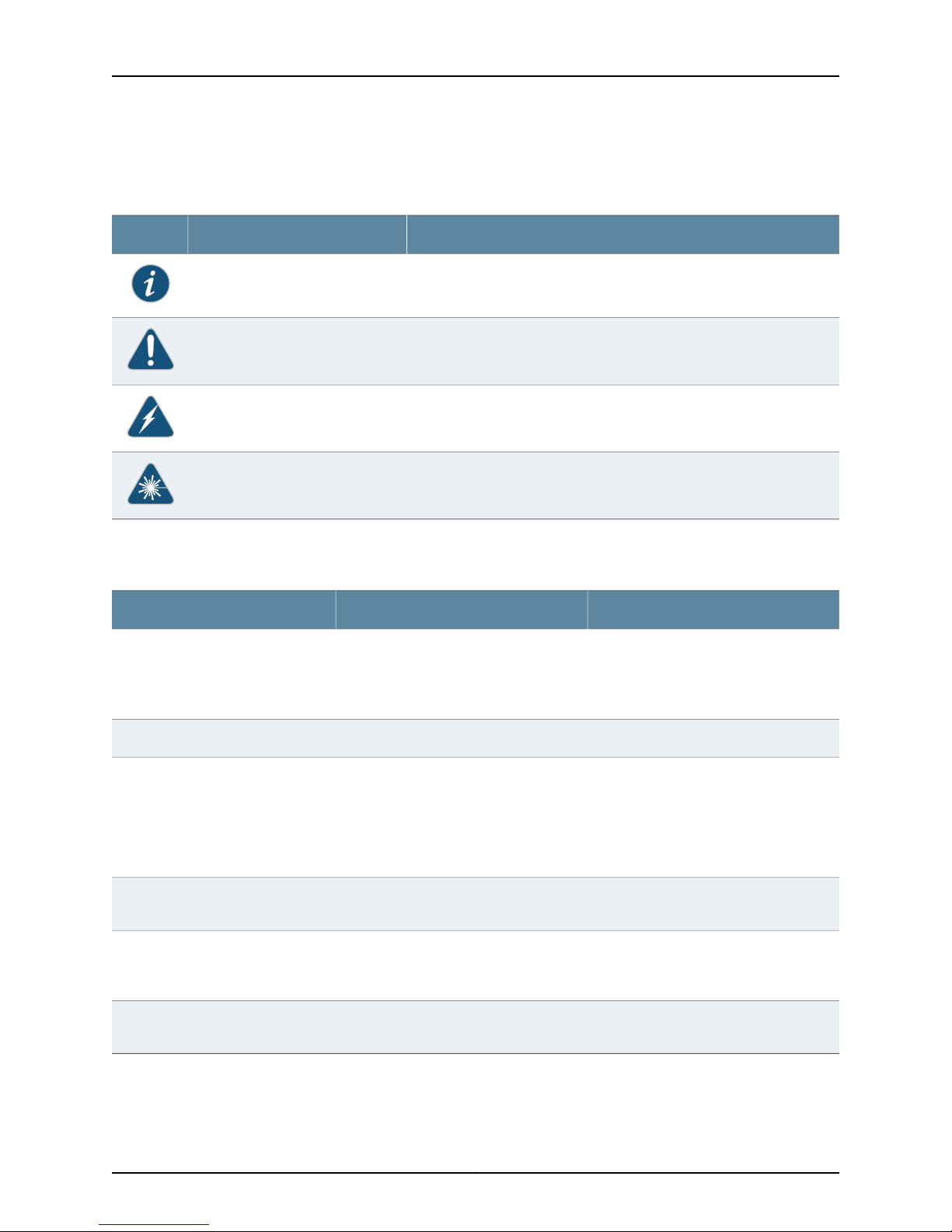
Table 1: Notice Icons
Table 1 on page xvi defines notice icons used in this guide.
DescriptionMeaningIcon
Indicates important features or instructions.Informational note
Indicates a situation that might result in loss of data or hardware damage.Caution
Alerts you to the risk of personal injury or death.Warning
Alerts you to the risk of personal injury from a laser.Laser warning
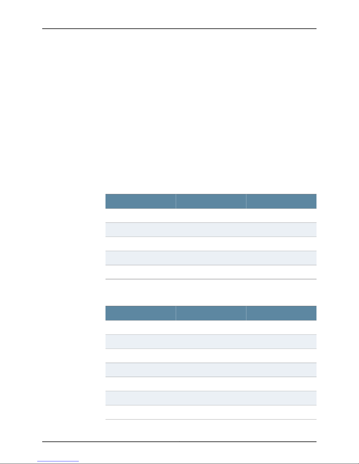
Table 2 on page xvi defines text conventions used in this guide.
Table 2: Text Conventions
Bold typeface like this
fixed-width font
Keynames linkedwith a plus (+) sign
Italics
•
Represents commands and keywords
in text.
•
Represents keywords
•
Represents UI elements
Represents information as displayed on
the terminal screen.
keys simultaneously.
•
Emphasizes words
•
Identifies variables
ExamplesDescriptionConvention
•
Issue the clock source command.
•
Specify the keyword exp-msg.
•
Click User Objects
user inputRepresents text that the user must type.Bold typeface like this
host1#
show ip ospf
Routing Process OSPF 2 with Router
ID 5.5.0.250
Router is an area Border Router
(ABR)
Ctrl + dIndicates that you must press two or more
•
The product supports two levels of
access, user and privileged.
•
clusterID, ipAddress.
The angle bracket (>)
Table 3 on page xvii defines syntax conventions used in this guide.
Indicates navigation paths through the UI
by clicking menu options and links.
Object Manager > User Objects > Local
Objects
Copyright © 2010, Juniper Networks, Inc.xvi
Page 17

Table 3: Syntax Conventions
About This Guide
ExamplesDescriptionConvention
terminal lengthRepresent keywordsWords in plain text
mask, accessListNameRepresent variablesWords in italics
Words separated by the pipe ( | )
symbol
Words enclosed in brackets followed
by and asterisk ( [ ]*)
variable to the left or right of this symbol. The
keywordor variable canbe optional or required.
can be entered more than once.
Represent required keywords or variables.Words enclosed in braces ( { } )
Documentation
Table 4 on page xvii describes documentation for NSM.
Table 4: Network and Security Manager Publications
DescriptionBook
Network and Security
Manager Installation Guide
Describes the steps to install the NSM management system on a
single server or on separate servers. It also includes information on
how to install and run the NSMuser interface.This guideis intended
for IT administrators responsible for the installation or upgrade of
NSM.
diagnostic | lineRepresent a choice to select one keyword or
[ internal | external ]Represent optional keywords or variables.Words enclosed in brackets ( [ ] )
[ level1 | level2 | 11 ]*Represent optional keywords or variables that
{ permit | deny } { in |out } { clusterId
| ipAddress }
Network and Security
Manager Administration
Guide
Network and Security
Manager Configuring
ScreenOS and IDP Devices
Guide
Describes how to use and configure key management features in
the NSM. Itprovides conceptual information, suggested workflows,
and examples. This guide is best used in conjunction with the NSM
Online Help,which provides step-by-step instructions for performing
management tasks in the NSM user interface (UI).
This guide is intended for application administrators or those
individuals responsible for owning the server and security
infrastructure and configuring the product for multiuser systems. It
is also intended for device configuration administrators, firewall
and VPN administrators, and network security operation center
administrators.
Describes NSM features related to device configuration and
management. It also explains how to configure basic andadvanced
NSM functionality, including deploying new device configurations,
managing security policies and VPNs, and general device
administration.
xviiCopyright © 2010, Juniper Networks, Inc.
Page 18

NSMXpress Series II User Guide
Table 4: Network and Security Manager Publications (continued)
DescriptionBook
Network and Security
Manager Online Help
Network and Security
Manager API Guide
Network and Security
Manager Release Notes
NSMXpress and NSM3000
User Guide
NSMXpress Series II User
Guide
Network and Security
Manager Configuring
Infranet Controllers Guide
Network and Security
Manager Configuring Secure
Access Devices Guide
Provides procedures for basic tasks in the NSM user interface. It
also includes a brief overview of the NSM system and a description
of the GUI elements.
Provides complete syntax and a description of the Simple Object
Access Protocol (SOAP) messaging interface to NSM.
Provides the latest information about features, changes, known
problems, resolved problems, and system maximum values. If the
information in the Release Notesdiffers from the information found
in the documentation set, follow the Release Notes.
Release Notes are included on the corresponding software CD and
are available on the Juniper Networks Website.
Describes how to set up and manage the NSM appliances as a
central manager or regional server.
Describes how to set up and manage the NSMXpress Series II
appliance as a central manager or regional server.
Provides details about configuring the device features for all
supported Infranet Controllers.
Provides details about configuring the device features for all
supported Secure Access Devices.
Network and Security
Manager Configuring EX
Series Switches Guide
Network and Security
Manager Configuring J
Series Services Routers and
SRX Series Services
Gateways Guide
Network and Security
Manager M Series and MX
Series Devices Guide
Documentation Feedback
We encourage you to provide feedback, comments, and suggestions so that we can
improve the documentation. You can send your comments to
techpubs-comments@juniper.net, or fill out the documentation feedback form at
https://www.juniper.net/cgi-bin/docbugreport/. If you are using e-mail, be sure to include
the following information with your comments:
Provides details about configuring the device features for all
supported EX Series platforms.
Provides details about configuring the device features for all
supported J Series Services Routers and SRX Series Services
Gateways.
Provides details about configuring the device features for M Series
and MX Series platforms.
Copyright © 2010, Juniper Networks, Inc.xviii
Page 19

•
Document name
•
Document part number
•
Page number
•
Software release version (not required for Network Operations Guides [NOGs])
Requesting Technical Support
Technical productsupport isavailablethrough theJuniper Networks Technical Assistance
Center (JTAC). If you are a customer with an active J-Care or JNASC support contract,
or are covered under warranty, and need postsales technical support, you can access
our tools and resources online or open a case with JTAC.
•
JTAC policies—For a complete understanding of our JTAC procedures and policies,
review the JTAC User Guide located at
http://www.juniper.net/us/en/local/pdf/resource-guides/7100059-en.pdf .
•
Product warranties—For product warranty information, visit
http://www.juniper.net/support/warranty/ .
About This Guide
•
JTAC Hours of Operation —The JTAC centers have resources available 24 hours a day,
7 days a week, 365 days a year.
Self-Help Online Tools and Resources
For quick and easy problem resolution, Juniper Networks has designed an online
self-service portal called the Customer Support Center (CSC) that provides you with the
following features:
•
Find CSC offerings: http://www.juniper.net/customers/support/
•
Search for known bugs: http://www2.juniper.net/kb/
•
Find product documentation: http://www.juniper.net/techpubs/
•
Find solutions and answer questions using our Knowledge Base: http://kb.juniper.net/
•
Download the latest versions of software and review release notes:
http://www.juniper.net/customers/csc/software/
•
Search technical bulletins for relevant hardware and software notifications:
https://www.juniper.net/alerts/
•
Join and participate in the Juniper Networks Community Forum:
http://www.juniper.net/company/communities/
•
Open a case online in the CSC Case Management tool: http://www.juniper.net/cm/
To verifyservice entitlement byproduct serial number,use our Serial Number Entitlement
(SNE) Tool: https://tools.juniper.net/SerialNumberEntitlementSearch/
Opening a Case with JTAC
You can open a case with JTAC on the Web or by telephone.
xixCopyright © 2010, Juniper Networks, Inc.
Page 20

NSMXpress Series II User Guide
•
Use the Case Management tool in the CSC at http://www.juniper.net/cm/ .
•
Call 1-888-314-JTAC (1-888-314-5822 toll-free in the USA, Canada, and Mexico).
For international or direct-dial options in countries without toll-free numbers, visit us at
http://www.juniper.net/support/requesting-support.html
Copyright © 2010, Juniper Networks, Inc.xx
Page 21

PART 1
Using NSMXpress Series II
Part 1 contains the following chapters:
•
Getting Started on page 3
•
Installing and Configuring NSM from the CLI on page 11
•
Configuring NSM from the Web Interface on page 29
1Copyright © 2010, Juniper Networks, Inc.
Page 22

NSMXpress Series II User Guide
Copyright © 2010, Juniper Networks, Inc.2
Page 23

CHAPTER 1
Getting Started
This version of NSMXpress Series II comes preconfigured as a regional server or central
manager.
This chapter contains the following sections:
•
About NSMXpress Series II on page 3
•
Hardware Installation on page 4
•
Initial Setup Configuration on page 8
About NSMXpress Series II
NSMXpress Series II is an appliance version of Network and Security Manager (NSM).
NSMXpress Series II simplifies the complexity of network administration by providing
single, integrated management interfaces that control device parameters.
This robust hardware management system installs in minutes with full high availability
(HA) support, making it easy to scale and deploy. Enterprise customers with limited
resources can benefit significantly from NSMXpress Series II because it eliminates the
need to have dedicated resources for maintaining a network and security management
solution.
NSMXpress Series II make it easy for administrators to control device configuration,
network settings, and security policy settings for multiple families of Juniper Networks
devices including:
•
IDP Series IntrusionDetection and PreventionAppliances andFirewall and VPN devices
running ScreenOS.
•
Devices running Junos OS, such as J Series Services Routers, SRX Series Services
Gateways, EX Series Ethernet Switches, M Series Multiservice Edge Routers, and MX
Series Ethernet Services routers.
•
SA Series SSL VPN Appliances
•
IC Series Unified Access Control Appliances
For a complete list of supported device families and platforms, see the Network and
Security Manager Administration Guide.
Up to 10 administrators can log into NSMXpress Series II concurrently.
3Copyright © 2010, Juniper Networks, Inc.
Page 24

NSMXpress Series II User Guide
Installation and Configuration Workflow
This guide explains the steps for installing and configuring NSMXpress Series II and for
configuring NSM.
1. Install the NSMXpress Series II appliance hardware.
2. Set up the NSMXpress Series II appliance using the serial port.
3. Configure the NSMXpress Series II software using either the CLI or the Web interface.
4. Configurethe NSMsoftware whichis preinstalled in theNSMXpress Series II appliance,
with site-specific parameters.
Hardware Installation
Werecommend that youinstall the NSMXpress Series II appliance on your LANto ensure
that it can communicate with your applicable resources, such as authentication servers,
DNS servers, internal Web servers through HTTP/HTTPS, external Web sites through
HTTP/HTTPS (optional),the Juniper update server via HTTP, Network File System(NFS)
file servers (optional), and client/server applications (optional).
NSMXpress Series II Ports
Table 5 on page 5 provides required port information on the NSMXpress Series II
appliance.
NOTE: If you decide to install an NSMXpress Series II appliance in your DMZ,
ensure that it can connect to your internal resources.
Copyright © 2010, Juniper Networks, Inc.4
Page 25

Table 5: Required Ports on NSMXpress Series II
Chapter 1: Getting Started
Depends on
ConfigurationInternetLANDescriptionPortDirection
NoNoYesSSH command-line management22In
443
8443
7800
7801
7802
7803
7804
22Out
23
NoNoYesWeb interface for administrator
login
YesYesLANWebinterfacefor listening for NSM
API messages.
NoYesYesConnections from managed
devices to the NSM appliance
NoNoYesConnections from the NSM GUI
Client to NSM
YesNoYesHeartbeat between peers in anHA
cluster
YesYesYesConnections from managed IDP
devices to NSM
YesYesYesConnections from devices running
Junos, Secure Access devices, or
Infranet Controller devices
NoYesYesSSH connection to new managed
device
YesNoYesTelnet connection to new
managed device
For more information on ports, refer to the Network and Security Manager Installation
Guide.
80
123
NoNoYesDNS lookups53
YesYesNoSystem Security Updates from
Juniper Networks
YesNoYesShared Disk portmap lookup111
YesYesYesNetworkTime Protocol (NTP) time
synchronization
YesNoYesShared Disk NFS connection2049
5Copyright © 2010, Juniper Networks, Inc.
Page 26
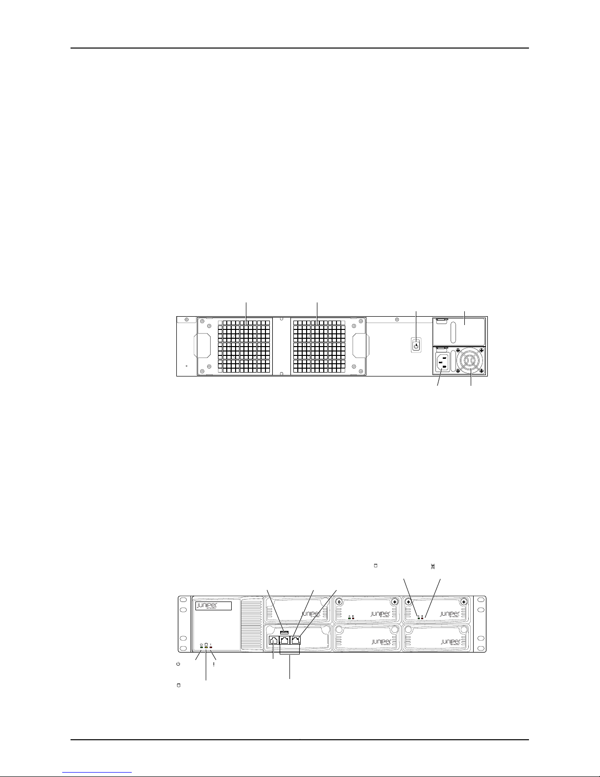
g040042
Power
supply
AC Power
supply
receptacle
AC Power Blank power
supply tray
switch
Fan 0 Fan 1
CONSOLE ETH1 ETH0
g040404
Power
LED
Hardware
LED
Hard disk LED
Left
LAN
LED
Right
LAN
LED
NSMXpress II
Hard disk
Activity LED
Hard disk
Failure LED
Network por ts
Console
port
USB
maintenance
port
NSMXpress Series II User Guide
Installing the NSMXpress Series II Hardware
Follow these steps to unpack theNSMXpress Series II appliance and connect it to your
network.
To install NSMXpress Series II:
1. Place the shipping container on a flat surface and remove the hardware components
with care.
2. Remove the NSMXpress Series II device from the shipping container and place it on
a flat surface.
3. Mount NSMXpress Series II in your server rack using the attached mounting brackets.
4. Plug the power cord into the AC receptacle on the rear panel.
Figure 1: Rear Panel of NSMXpress Series II
If your NSMXpress contains two power supplies, plug a power cord into each AC
receptacle.
5. Plug the other end of the power cord into a wall socket.
If your NSMXpress Series II contains two power supplies, plug each power cord into
a separate power circuit to ensure that the NSMXpress Series II continues to receive
power if one of the power circuits fails.
6. Plug the Ethernet cable into the network port marked ETH0 on the front panel. See
Figure 2 on page 6.
Figure 2: Front Panel of NSMXpress Series II
Copyright © 2010, Juniper Networks, Inc.6
Page 27
Chapter 1: Getting Started
7. Plug the console cable with the DB9 to RJ45 adapter into the console port. See Figure
2 on page 6.
This cable was shipped with your NSMXpress Series II appliance. See Table 7 on
page 7.
8. Push the power button on the rear panel. See Figure 1 on page 6.
The green LED on the bottom left corner of the front panel turns on. The NSMXpress
Series II hard disk LED turns onwhenever theappliance reads data fromor writesdata
to an NSMXpress Series II hard disk.
The internal port uses two LEDs to indicate the LAN connection status, which is
described in Table 6 on page 7.
Hardware installation is now complete. The next step is to set up the software, as
described in “Initial Setup Configuration” on page 8.
Table 6 on page 7 provides LED information for the Ethernet ports.
Table 6: Ethernet Port LEDs
LED2LED 1LAN Status
OffOff10 Mbps connection
OffGreen100 Mbps connection
OffOrange1000 Mbps connection
BlinkingOrange, Green, or OffData is being transferred
OffOffNo connection
Table 7 on page 7 provides RJ-45 Console Connector Pinout information.
Table 7: RJ-45 Console Connector Pinout
DescriptionSignalPin
Request to SendRTS Output1
Data Terminal ReadyDTR Output2
Transmit DataTxD Output3
Chassis GroundGND4
Chassis GroundGND5
Receive DataRxD Input6
Data Set ReadyDSR Input7
7Copyright © 2010, Juniper Networks, Inc.
Page 28

NSMXpress Series II User Guide
Table 7: RJ-45 Console Connector Pinout (continued)
Initial Setup Configuration
When you first turn on an unconfigured NSMXpress Series II appliance, you need to enter
basic network andmachine information through theserial console to makeyour appliance
accessible to the network. After entering these settings, you can continue configuring
the appliance using the CLI or the Web interface. You are not prompted for the initial
setup information again.
This section describes the requiredserial console setupand the tasks you need to perform
when connecting to your NSMXpress Series II appliance for the first time:
•
Boot NSMXpress Series II on page 8
•
Set Up Your Appliance on page 9
DescriptionSignalPin
Clear to SendCTS Input8
Boot NSMXpress Series II
To configure NSMXpress Series II for the first time, you must attach your NSMXpress
Series II appliance to a console terminal running an emulation utility such as
HyperTerminal.
1. Configure a console terminal or terminal emulation utility to use the following serial
2. Connect the terminal or laptop to the console cable plugged into the NSMXpress
3. Turn on the NSMXpress Series II appliance.
connection parameters:
•
9600 bits per second
•
8-bit no parity (8N1)
•
1 stop bit
•
No flow control
Series II appliance console port.
When the NSMXpress Series II appliance is powered on, the serial console displays
diagnostic information before proceeding to the boot countdown. When complete,
the serial console displays the login prompt terminal emulator.
NSMXpress.juniper.net login:
4. Enter admin as your default login name.
5. Enter abc123 as your default password.
6. Change your default password when prompted. Enter the default password first,
followed by your new password. All passwords are case-sensitive.
Copyright © 2010, Juniper Networks, Inc.8
Page 29

Set Up Your Appliance
Chapter 1: Getting Started
This section provides the minimuminformation necessary tomake your appliance active
on the network.
To set up your appliance either as a regional server or a central manager, follow these
steps:
1. Enter the IP address for interface eth0 and press Enter.
2. Enter the subnet mask for interface eth0 and press Enter.
3. Enter the default route or default gateway address for interface eth0 and press Enter.
Applying changes...
Re-loading database
ip_tables: (C) 2000–2002 Netfilter core team
ip_tables: (C) 2000–2002 Netfilter core team
ip_tables: (C) 2000–2002 Netfileter core team
Done!
Your NSMXpress is now active on the network.
To configure your system via a web browser, connect to:
https://10.150.43.205/administration
To configure your system via command line, type:
nsm_setup
For operation of NSM server, switch to user “nsm”.
Please consult NSM product documentation for details.
[admin@NSMXpress ~]$
To complete the setup process using the CLI, go to “CLI Configuration” on page 9. To
complete the setup process usingthe Webinterface, go to “Web Interface Configuration”
on page 10.
CLI Configuration
To finish initial setup from the CLI, use the following steps. If you are logged in, enter
nsm_setup at the command prompt.
If you are not logged on, follow these steps:
1. Enter your admin username, and then press Enter.
2. Enter your password and then press Enter.
Juniper NSMXpress OS build 2.105498
NSM 2010.4r1Kernel 2.6.9–55.0.2.ELsmp on an i686
NSMXpress.Juniper.net login: admin
Password:
Last login: Tue May 27 17:20:25 on ttyS0
Run NSMXpress system setup? [y/N]
3. Enter y to run the system setup program from the CLI.
9Copyright © 2010, Juniper Networks, Inc.
Page 30

NSMXpress Series II User Guide
NOTE: These values are not case-sensitive. However, the uppercase N
indicates it is the default value. Any keystroke, including Enter but not y
or Y, accepts the default value.
4. Go to “Installing and Configuring NSM from the CLI” on page 11 for information about
how to install and configure NSM on your NSM appliance from the CLI.
NSMXpress Series II Users
NSMXpress Series II has three user levels. All users log in as the “admin” user. To use the
command line to administer NSM, change tothe “nsm”user. For advancedadministration,
change to the “root” user.
The following users are available to manage NSMXpress Series II.
•
“admin” user—Logs into the NSMXpress Series II setup program and changes to “nsm”
user or “root” user from the command line.
•
“nsm” user—Administers NSM services. To change to the “nsm” user from the “admin”
user, go to the $ prompt, enter sudo su - nsm for the $ nsm prompt, then enter the
“admin” password you set when logging into the NSMXpress Series II appliance. To
return to the “admin” user, enter exit at the $ prompt.
•
“root” user—Administers advanced system settings. To change to “root” user from the
“admin” user, go to the $ prompt, enter sudosu - root for the # root prompt, then enter
the “admin” password you set when logging into the NSMXpress Series II appliance.
To return to the “admin” user, enter exit from the # prompt.
Web Interface Configuration
To finish initial setup from a Web interface, use the following steps.
1. Copy the URL (starting with https://) from the terminal emulator after installing
NSMXpress Series II:
Your NSMXpress is now active on the network.
To configure your system via a web browser, connect to:
https//10.150.43.205/administration
2. Open a Web browser and paste the URL into the address text box.
3. Press Enter to open the NSMXpress Series II login page.
4. Enter the admin user name and password and then click Login.
5. See “Configuring NSM from the Web Interface” on page 29 for details about how to
install and configure NSM on your NSMXpress Series II appliance from the Web
interface.
Copyright © 2010, Juniper Networks, Inc.10
Page 31

CHAPTER 2
Installing and Configuring NSM from the
CLI
This chapter describes how to install and configure NSM on your NSMXpress Series II
appliance from the command-line interface (CLI). It contains the following sections:
•
Navigating the Menus on page 11
•
Configuring the NSM Software on page 13
•
Configuring a Regional Server on page 14
•
Configuring the Central Manager on page 19
•
Configuring Standard Configuration Options on page 23
•
NSMXpress Series II Default Restoration on page 27
Navigating the Menus
As you configure NSM on your NSMXpress Series II appliance, the following standard
navigational menu options are available to you. This section provides information on
general options you can use during setup and configuration. These options include:
•
General Options on page 11
•
Using nsm_setup on page 12
General Options
The NSM Configuration Main Menu has the following options:
NSM Configuration Main Menu
1> Management IP [10.150.43.205]
The IP address on this server that will be
used for management
2> NSM 'super' password []
Password for 'super' user
3> GUI server one-time password []
Password to initiate authentication
between HA peers and to Central Manager.
This password must be the same for all
NSM servers in this installation.
11Copyright © 2010, Juniper Networks, Inc.
Page 32

NSMXpress Series II User Guide
4> NSM License type []
Specify a license file, or select "Base Install"
to use the built-in limited device license.
A> Apply settings
C> Cancel all changes and quit
R> Redraw menu
Choice [1-4,A,C,R]:
To select an option, enter the number at the prompt and then press Enter. The following
options are available on most menus:
•
Numbered Options—Enter setting options by number (1, 2, and so on) to access
individual parameters or open menus.
•
Apply settings—Enter A to apply and save any modifications you have made and take
you out of the setup program.
•
Cancel all changes and quit—Enter C to leave the setup program without saving any
changes you made since you last saved.
Using nsm_setup
•
Redraw menu—Enter R to redraw the screen text.
•
Main Menu/Return to Main Menu—Enter M to return to the main menu. This option is
last on most menus.
•
Quit—Enter Q to exit from the setup program. You will be prompted to save or cancel
any changes you made since you last saved:
Q> Quit
R> Redraw menu
Choice [1–9,Q,R]: Q
After initial setup, you can cancel out of the setup program and later return to it. Follow
these steps to return to theNSMXpress Series II setup program.The steps inthis procedure
assume thatNSMXpress Series IIis connected to a computer runninga terminalemulation
program. If not, see “Initial Setup Configuration” on page 8 for details.
NOTE: Run nsm_setup with your “admin” user login only. Do not run
nsm_setup as an “nsm” user.
To return to the setup program after the initial setup:
1. Turn on the NSM appliance and wait for the login prompt:
Juniper NSMXpress NSM 2010.4r1 Kernel 2.6.9–42.0.8.ELsmp on an i686
NSMXpress.juniper.net logon: admin
Password:
Las Login: Tue May 17 09:43:50 on tty50
Run NSMXpress system setup? [y/N] N
Copyright © 2010, Juniper Networks, Inc.12
Page 33

Chapter 2: Installing and Configuring NSM from the CLI
To start system setup manually, type:
nsm_setup
for operation of NSM server, switch to user “nsm”.
Please consult NSM product documentation for details.
[admin@NSMXpress ~]$
2. Log in using your “admin” user name and password.
3. Enter nsm_setup at the prompt.
4. Enter your password and press Enter.
5. From the Settings menu:
•
For a regional server, enter 9, and then enter 1 to display the NSM Configuration
Main Menu for typical settings, or enter 2 for custom settings.
•
For a central manager, enter 9 to display the Configuration Main Menu.
Configuring the NSM Software
After you log in as an “admin” user, an initial setup script walks you through additional
configurationsystemsettings before finalizing theNSM installation. This section describes
that setup process.
The steps in this procedure assume you:
•
Have completed all appropriate steps in “Getting Started” on page 3.
•
Have a console terminal or terminal emulation utility running.
•
See the following command output in the emulation utility window:
Your NSMXpress is now active on the network.
To configure your system via a web browser, connect to:
https://10.150.43.205/administration
To configure your system via command line, type:
nsm_setup
For operation of NSM server, switch to user “nsm”
Please consult NSM product documentation for details.
[admin@NSMXpress “]$
Your NSMXpress Series II appliance comes preconfigured as a regional server or a central
manager, as described in the following sections:
•
Configuring a Regional Server on page 14
•
Configuring the Central Manager on page 19
13Copyright © 2010, Juniper Networks, Inc.
Page 34

NSMXpress Series II User Guide
Configuring a Regional Server
For details onusing thegeneral setup menuitems, see “Navigating the Menus” on page 11.
To configure the regional server, select one of the following options by number:
•
Typical Settings—Enter 1 to select typical settings. This option provides a simplified
menu to install a regional server. When using these options neither HA nor statistical
report server (SRS) can be in use.
•
Custom Settings—Enter 2 to select custom settings. This option provides full access
to all configuration options including HA and SRS for regional server.
The following sections provide details of these options:
•
Configuring Typical Settings on page 14
•
Configuring Custom Settings on page 15
Configuring Typical Settings
This section describes the options that are available for a typical installation for the
regional server:
NSM Configuration Main Menu
1> Management IP [10.150.43.205]
The IP address on this server that will be
used for management
2> NSM 'super' password []
Password for 'super' user
3> GUI server one-time password []
Password to initiate authentication
between HA peers and to Central Manager.
This password must be the same for all
NSM servers in this installation.
4> NSM License type []
Specify a license file, or select "Base Install"
to use the built-in limited device license.
A> Apply settings
C> Cancel all changes and quit
R> Redraw menu
Choice [1-4,A,C,R]:
You have the following options:
•
Management IP—Enter 1 to select interface eth0 or eth1 as the primary IP address for
your management server. Once configured, the setup program displays the IP address
for the interface you selected.
•
NSM ‘super’ password—Enter 2 to specify an NSM super password. This password
must be at least eight characters long and is case-sensitive. This password is used by
Copyright © 2010, Juniper Networks, Inc.14
Page 35

the NSM superuser (also referred to as the NSM administrator). This user has the
highest level of privilege in NSM.
•
GUI Server one-time password—Enter 3 to specify this password. This password
authenticates this server to its peers in a high-availability configuration, and to the
central manager.
•
NSM License type [Base Install]—Enter 4 to specify the license option. Enter Base
Install to use the built-in limited device license for as many as 25 devices. This option
is the default. Otherwise, enter the filename of the license file you purchased from
Juniper Networks that permits you to manage more than 25 devices.
For additional details about NSM licensing, see the Network and Security Manager
Installation Guide.
Configuring Custom Settings
This section describes the custom options that are available for a regional server
configuration. The custom options include the typical options described in the previous
section as well as the following two options:
5> Menu: High Availability [Off]
Chapter 2: Installing and Configuring NSM from the CLI
6> Menu: Advanced Options
You have the following options:
•
High Availability—Enter 5 to open a menu to configure HA.
•
AdvancedOptions—Enter 6to open a menuof additionalconfigurableoptions, including
the port number for receiving messages through the NSM API, remote database
replication details, and the Statistical Report Server (SRS).
The following sections provide details about these options:
•
Configuring High Availability on page 15
•
Configuring Advanced Options on page 17
Configuring High Availability
NOTE: When installing NSM regional server in a high availability configuration
with a shared disk, you must first revert the system to factory default values
using the boot menu. See “NSMXpress Series II Default Restoration” on
page 27 for details.
The following options are available to configure high availability (HA) on the regional
server.
•
High Availability—Enter 1 to turn HA on or off.
•
Primary Status—Enter 2 to specify the NSMXpress Series II appliance as either the
primary or secondary server. At the next prompt, enter y for the primary server. Enter
n for a secondary server.
15Copyright © 2010, Juniper Networks, Inc.
Page 36

NSMXpress Series II User Guide
•
HA Remote IP—Enter 3 to specify the IP address for the HA peer in the HA cluster.
•
HA Link Failure Detection IP—Enter 4 to specify the IP address of a machine outside
the HA cluster that you can ping to verify connection status.
•
HA Inter-server password—Enter 5 to specify the heartbeat password used between
the primary and secondary servers.
•
Menu: Shared Disk—Enter 6 to open a menu to help you configure a shared disk.
NSMXpress Series II supports shared disks with NFS only. Becauseof the data-intensive
nature of NSM, we recommend gigabit speed links (1000 Mbps) for shared disk usage.
For more information on options available to you for custom settings, refer to the
Network and Security Manager Installation Guide.
1> Shared Disk: Gui Server [n]
If 'y', data directory for GUI Server is a shared disk partition
2> Shared Disk: Device Server [n]
If 'y', data directory for Device Server is a shared disk partition
3> Shared Disk Source (NFS) []
Source of shared disk, e.g. /dev/sdc1 or server:/share
4> Shared Disk NFS Mount Options [rw]
Options when mounting shared disk e.g. rw, intr, tcp, soft, timeo=2
5> Return to High Availability menu
•
Menu: HA Links—Enter 7 to open a menu to help you configure the second HA link in
the HA cluster. Use the items in this menu to set up a redundant link for the HA cluster.
If you are going to use a second link, you need to set the IP address for eth1 before
configuring this setting (see “Setting Interface Options” on page 24 for more
information). Setting a redundant link is optional. For more information on options
available to you for custom settings, refer to the Network and Security Manager
Installation Guide.
If you configure HA with just one heartbeat link, then device management traffic and
data replication traffic both usethat link.If youconfigure two links, device management
traffic uses the first link and data replication uses the second.
If the HA link count is set to 1, the only options available are to set the HA link count
and to return to the High Availability menu. If the HA link count is set to 2, all options
are available.
1> HA Link count [2]
Number of heartbeat links between the Primary and SecondaryServers.
2> HA Link 2 Local IP []
IP address for this machine's secondary heartbeat link
3> HA Link 2 Remote IP []
IP address for the peer's secondary heartbeat link
4> HA Remote Replication IP []
IP address used for remote HA replications
5> Return to High Availability Menu
Copyright © 2010, Juniper Networks, Inc.16
Page 37

Chapter 2: Installing and Configuring NSM from the CLI
•
Menu: HA Advanced Settings—Enter 8 to open a menu to configure HA advanced
settings. For more information on options available to you for custom settings, refer
to the Network and Security Manager Installation Guide.
1> HA Heartbeat Frequency [15]
Time interval in seconds between heartbeat messages (Default is 15
seconds)
2> HA Heartbeat Failure Threshold [4]
Number of missing heartbeat messages before automatic switchover
occurs (Default is 4 missing messages)
3> HA Data Replication Timeout [1800]
Rsync Command Replication Timeout (Default is 1800 seconds)
4> Return to high Availability menu
Configuring Advanced Options
The Advanced Options menu provides the following configuration options:
Menu: Advanced Options
1> https port for NBI service [8443]
The port number to listen for NBI
(Default is 8443)
2> Menu: Remote Replication of Database [Off]
3> Menu: SRS [Off]
M> Main Menu
R> Redraw menu
Choice [1-3,M,R]:
You have the following options:
•
https portfor NBIservice—Enter 1 to change the port number for listeningfor messages
for the NSM API. In response to the prompt, enter a value in the range 1025 through
65535. Any number outside this range returns an error message. The default value is
8443.
•
Menu: Remote Replication of Database—Enter 2 to display a menu of options for
configuring thetime of day to take the backup, the location of the backup, and timeout
value.
•
Menu: SRS—Enter 3 to open a menu to configure Statistical Report Server (SRS).
The following sections provide details about configuring remote backup and SRS:
•
Enabling and Configuring Remote Replication of the Database on page 18
•
Enabling and Configuring the Statistical Report Server on page 18
17Copyright © 2010, Juniper Networks, Inc.
Page 38

NSMXpress Series II User Guide
Enabling and Configuring Remote Replication of the Database
On the Advanced Options menu, enter 2 to open a menu that allows you to mirror the
daily backup to an external server. You can toggle it on or off. After you turn it on, use the
menu options to configure this option:
1> Remote Replication of Database [n]
If 'y', local backups will be sent to a remote backup machine
2> Hour of day to Replicate Database [02]
Hour to start a backup
3> Remote backup IP [ ]
IP address of a remote backup machine
4> Remote Replication Timeout (seconds) [1800]
Rsync Command Backup Timeout (seconds)
(Default is 1800 seconds)
The screen always shows the current status of the remote backup database. If no status
exists, the option has not yet been configured.
•
Remote Replication of Database—Enter 1 to turn remote replication on or off. At the
next prompt, enter y to change the state.
•
Hour of day to Replicate Database—Enter 2 to start the backup at the specified time.
The valid range is 00-23.
•
Remote Backup IP—Enter 3 to specify the IP address of the remote backup machine.
Backup information is copied to the /var/netscreen/dbbackup directory on the remote
server. The “nsm” user must exist on both servers and you must establish an SSH trust
relationship. See the Network and Security Manager Installation Guide for details.
•
Remote Replication Timeout—Enter 4 to time out the remote backup. The valid range
is 1-65535 seconds.
Enabling and Configuring the Statistical Report Server
The following options are available to configure the statistical report server (SRS):
NOTE: SRS must be installed on a separate server from NSM.
1> SRS [n]
Statistical Report Server will be used with this GUI Server
2> SRS DB IP []
Database server IP address
3> SRS DB Type [pgsql]
Database Type
4> SRS Database Name [netscreen]
Database name
5> SRS DB Owner Name [netscreen]
Database user name
Copyright © 2010, Juniper Networks, Inc.18
Page 39

Chapter 2: Installing and Configuring NSM from the CLI
6> SRS DB Owner Password []
Database password
You have the following options:
•
SRS—Enter 1 to turn the statistical report server on or off. At the next prompt, enter y
to turn it on or n to turn it off. If you turn it on, the SRS will be used with the GUI Server.
•
SRS DB IP—Enter 2 to specify the IP address for the server on which you have installed
the SRS database server.
•
SRS DB Type—Enter 3 to specify the database type. The options are pgsql (default),
oracle, and mssql.
•
SRS Database Name—Enter 4 to specify the name of the SRS database on the SRS
server. The default value for this option is netscreen.
•
SRS DB Owner Name—Enter 5 to specify the name of the SRS database owner. The
default value for this option is netscreen.
•
SRS DB Owner Password—Enter 6 to specifythe ownerpasswordfor theSRS database.
At least eight characters are required. The password is case-sensitive.
Click Submit to save the options and return to the NSM Configuration Main Menu.
Configuring the Central Manager
For details about using the general setup menu items, see “Navigating the Menus” on
page 11.
This sectiondescribes the options that are available for acentral managerconfiguration.
The central manager main menu options are:
NSM Configuration Main Menu
1> Management IP [10.150.43.205]
The IP address on this server that will be
used for management
2> NSM 'super' password []
Password for 'super' user
3> GUI server one-time password []
Password for authentication between
HA peers and to all Regional Servers
4> Menu: High Availability [Off]
5> Menu: Advanced Options
A> Apply settings
C> Cancel all changes and quit
R> Redraw menu
Choice [1-5,A,C,R]:
You have the following options:
19Copyright © 2010, Juniper Networks, Inc.
Page 40

NSMXpress Series II User Guide
•
Management IP—Enter 1 to select interface eth0 or eth1 as the primary IP address for
your management server. Once configured, the setup program displays the IP address
for the interface you selected.
•
NSM super password—Enter 2 to specify an NSM “super” password. This password
must be at least eight characters long and is case-sensitive. This password is used by
the NSM superuser (also referred to as the NSM administrator). This user has the
highest level of privileges in NSM.
•
GUI Server one-time password—Enter 3 to specify this password. This password
authenticates this server to its peer in a high-availability configuration, and to regional
servers.
•
Menu: HighAvailability—Enter 4 to opena menuto configure HA. See “Configuring High
Availability” on page 20.
•
Menu: Advanced Options—Enter 5 to open a menu of additional options, including the
port number for receiving messages through the NSM API, and remote database
replication details.
The following sections provide procedures for configuring HA and advanced options:
•
Configuring High Availability on page 20
•
Configuring Advanced Options on page 22
Configuring High Availability
To configure high availability (HA), from the NSM Configuration Main menu, enter 4. The
NSMXpress Series II appliance displays the High Availability menu:
1> High Availability [n]
Whether to enable HA on this server or not
2> Primary Status [y]
If 'y', this machine is a Primary Server
and if 'n' this machine is a Secondary
Server
3> HA Remote IP []
IP address for the peer's primary
heartbeat link
4> HA Link Failure Detection IP []
IP address outside the HA cluster
5> HA Inter-server password []
Shared password for heartbeat
6> Menu: Shared Disk [Off]
7> Menu: HA Links
8> Menu: HA Advanced Settings
The following options are available to configure HA.
Copyright © 2010, Juniper Networks, Inc.20
Page 41

Chapter 2: Installing and Configuring NSM from the CLI
•
High Availability—Enter 1 to turn HA on or off.
•
Primary Status—Enter 2 to set NSMXpress Series II as either the primary or secondary
server. At the next prompt, enter y for a primary server; enter n for a secondary server.
•
HA Remote IP—Enter 3 to set the IP address for the HA peer in the HA cluster.
•
HA Link Failure Detection IP—Enter 4 to set the IP address of a computer outside the
HA cluster that you can ping to verify connection status.
•
HA Inter-server password—Enter 5 to set the heartbeat password used between the
primary and secondary servers.
•
Menu: Shared Disk—Enter 6 to open the Shared Disk menu.
The options in this menu help you configure a shared disk. NSM supports shared disk
via NFS only. Due to the data-intensive nature of NSM, we recommend gigabit speed
links (1000 Mbps) for shared disk use. For more information on custom settings, refer
to the Network and Security Manager Installation Guide.
1> Shared Disk: Gui Server [n]
If 'y', data directory for GUI Server
is a shared disk partition
2> Shared Disk Source (NFS) []
Source of shared disk, e.g. /dev/sdc1
or server:/share
3> Shared Disk NFS Mount Options []
Options when mounting shared disk
e.g. rw,intr,tcp,soft,timeo=2
4> Return to High Availability menu
•
Menu: HA Links—Enter 7 to open the HA Links menu.
The options in this menu help you configure the second HA link in the HA cluster. If you
are going to use a second link, you needto set the IP address for eth1 before configuring
this setting (see“Setting Interface Options” on page24 for details). Setting aredundant
link is optional. For more information on options available to you for custom settings,
refer to the Network and Security Manager Installation Guide.
If the HA link count is set to 1, the only options available are to set the HA link count
and to return to the High Availability menu. If the HA link count is set to 2, all options
are available.
1> HA Link count [2]
Number of heartbeat links between the Primary and Secondary
Server.
2> HA Link 2 Local IP []
IP address for this machine's secondary heartbeat link
3> HA Link 2 Remote IP []
IP address for the peer's secondary heartbeat link
4> HA Remote Replication IP []
IP address used for remote HA replications
5> Return to High Availability menu
21Copyright © 2010, Juniper Networks, Inc.
Page 42

NSMXpress Series II User Guide
•
Menu: HA Advanced Settings—Enter 8 to open the HA Advanced Settings menu. For
more information about HA advanced settings, refer to the Network and Security
Manager Installation Guide.
1> HA Heartbeat Frequency [15]
Time interval in seconds between heartbeat messages (Default is 15
seconds)
2> HA Heartbeat Failure Threshold [4]
Number of missing heartbeat messages before automatic switchover
occurs (Default is 4 missing messages)
3> HA Data Replication Timeout [1800]
Rsync Command Replication timeout (Default is 1800 seconds)
4> Return to High Availability menu
Configuring Advanced Options
To configure advanced options, from the NSM Configuration Main menu, enter 5.
NSMXpress Series II displays the Advanced Options menu:
Menu: Advanced Options
1> https port for NBI service [8443]
The port number to listen for NBI
(Default is 8443)
2> Menu: Remote Replication of Database [Off]
M> Main Menu
R> Redraw menu
Choice [1-2,M,R]:
You have the following options:
•
https portfor NBIservice—Enter 1 to change the port number for listeningfor messages
for the NSM API. In response to the prompt, enter a value in the range 1025 through
65535. Any number outside this range returns an error message. The default value is
8443.
•
Menu: Remote Replication of Database—Enter 2 to display a menu of options for
configuring thetime of day to take the backup, the location of the backup, and timeout
value. See “Enabling andConfiguring Remote Replication of the Database” on page 22.
Enabling and Configuring Remote Replication of the Database
On the Advanced Options menu, enter 2 to open a menu that allows you to mirror the
daily backup to an external server. You can toggle it on or off. After you turn it on, use the
menu options to configure this option:
1> Remote Replication of Database [n]
If 'y', local backups will be sent to a remote backup machine
2> Hour of day to Replicate Database [02]
Hour to start backup
Copyright © 2010, Juniper Networks, Inc.22
Page 43

Chapter 2: Installing and Configuring NSM from the CLI
3> Remote Backup IP []
IP address of a remote backup machine
4> Remote Replication Timeout (seconds) [1800]
Rsync Command Backup Timeout (seconds)
(Default is 1800 seconds)
The screen always shows the current status of the remote backup database. If no status
exists, the option has not yet been configured.
•
Remote Replication of Database—Enter 1 to turn remote replication on or off. At the
next prompt, enter y to change the state.
•
Hour of day to Replicate Database—Enter 2, and then specify the hour to start the
backup. The valid range is 00 through 23.
•
Remote Backup IP—Enter 3 to specify the IP address of the remote backup server.
Backup information is copied to the /var/netscreen/dbbackup directory on the remote
server. The “nsm” user must exist on both servers and you must establish an SSH trust
relationship. See the Network and Security Manager Installation Guide for details.
•
Remote Replication Timeout—Enter 4 to change the timeout period for the remote
backup. The valid range is 1 through 65535 seconds.
Configuring Standard Configuration Options
After the initial setup, continue configuring typical options, including the following tasks.
Follow the setup prompts on the main menu to set or modify these options. Your
configuration options (with the exception of any password changes) will not take effect
until you apply the changes.
Run nsm_setup to access these options on the NSMXpress Series II Settings Menu:
•
Changing the Password on page 23
•
Setting Interface Options on page 24
•
Setting Routing Options on page 24
•
Changing the NSMXpress Series II Hostname on page 25
•
Adding DNS Servers on page 25
•
Setting the System Time on page 25
•
Forwarding Local Status E-mails on page 26
•
Updating System Security on page 26
•
Saving Setup Options on page 27
Changing the Password
To change your password:
1. On the NSMXpress Series II Settings Menu, enter 1 at the prompt.
2. Enter y when prompted to change the password for an “admin” user.
23Copyright © 2010, Juniper Networks, Inc.
Page 44

NSMXpress Series II User Guide
3. Type the new password and press Enter.
4. Retype the new password and press Enter.
Setting Interface Options
NSMXpress Series II has twoports labeled ETH0 andETH1. During initial setup,you specify
the eth0interfaceoptions. Use this menu to set interface options for eth1or modify either
interface.
To set or modify interface options:
1. On the NSMXpress Series II Settings menu, enter 2 at the prompt. The menu shows
Your password ischanged andthe setupprogram returns you to theNSMXpress Series
II Settings menu.
NOTE: If you are going to use a second link, you need to configure an IP
address for eth1 before configuring this setting.
the existing status of each interface.
2. Set or modify options for one of the interfaces by selecting one ofthe following options:
•
1 to modify eth0.
•
2 to set or modify eth1.
3. Make the following selection for interface options by selecting one of the following
options:
•
1 to change the IP address and return to the NSMXpress Series II Settings menu.
•
2 to go to the next step.
4. Make the following selection for physical parameters (such as interface speed) by
selecting one of the following options:
•
1 to set the autonegotiate option and return to the main menu.
•
2 to set the physical parameters manually and go to the next step.
5. Select the interface speed by entering one of the following options:
•
1 for 10 Mbps and go to the next step.
•
2 for 100 Mbps and go to the next step.
•
3 for 1000 Mbps and go to the next step.
6. Enter 1 for full duplex or 2 for half duplex, and then return to the NSMXpress Series II
Settings menu.
Setting Routing Options
To set or modify routing options:
Copyright © 2010, Juniper Networks, Inc.24
Page 45

1. On the NSMXpress Series II Settings menu, enter 3 at the prompt.
2. Enter one of the following options:
•
1 to change default gateway options.
Follow the prompts to change the IP address of the default gateway and return to
the NSMXpress Series II Settings menu.
•
2 to change the static routing options.
Follow the prompts to add a new static route and return to the NSMXpress Series II
Settings menu.
Changing the NSMXpress Series II Hostname
To change the hostname:
1. On the NSMXpress Series II Settings menu, enter 4 at the prompt.
2. Enter y at the verification prompt to continue.
3. Enter the new hostname and press Enter to return to the Settings menu.
Chapter 2: Installing and Configuring NSM from the CLI
Adding DNS Servers
You can add up to three DNS servers. Enter each one using dotted decimal notation.
Each additionreturns you to the main menu. If youwant to add more DNS servers, repeat
the following procedure.
To add the DNS servers:
1. On the NSMXpress Series II Settings menu, enter 5 at the prompt.
2. Enter 1 to add a name server.
3. When prompted, enter the new nameserver in dotted decimal notation.
Setting the System Time
You can change time zones or the Network Time Protocol (NTP) configuration. The
default time zone is set for Pacific Standard Time (PST)/Pacific Daylight Time (PDT).
Select time zones in the following order:
•
NOTE: If a hostname consisting of 4 or more labels is changed to a different
hostname, also with 4 or more labels, the previous hostname alias might
remain in the /etc/hosts file. This condition can be corrected by manually
editing the /etc/hosts file.
Continent or ocean
•
Country
•
Region
25Copyright © 2010, Juniper Networks, Inc.
Page 46

NSMXpress Series II User Guide
NOTE: NTP is disabled by default. We recommend that you enable this
option to ensure that the time is always accurate.
To change time options:
1. On the NSMXpress Series II Settings menu, enter 6 at the prompt.
2. Enter 1 to change the time zone.
Follow the prompts to find the time zone you want based on the options listed earlier.
The final selection returns you to the NSMXpress Series II Settings menu.
3. Enter 2 to set NTP servers.
NTP servers automatically set the system clock based on external time sources.
4. Enter one of the following values at the prompt:
•
1 to enable or disable NTP.
•
2 to add an NTP server.
The remaining numbered options allow you to remove an NTP server from the list.
5. Follow the prompts to enable, set, or delete the NTP servers and return to the
NSMXpress Series II Settings menu.
Forwarding Local Status E-mails
You can use this option to forward all local root e-mail messages to an e-mail address.
You can add an unlimited number of e-mail addresses in addition to mailing lists to help
manage large numbers of recipients.
To set the Forward Local Status:
1. On the NSMXpress Series II Settings menu, enter 7 at the prompt.
2. Enter 1 to add or change the recipient.
3. Enter 2 to remove the recipient.
Updating System Security
System security updates are NSMXpress Series II operating system-level patches that
protectthe system against any futurereported security vulnerabilities.NSMXpress Series
II checks for new updates daily by connecting to Juniper Networks.
To manage system security updates:
1. On the NSMXpress Series II Settings menu, enter 8 at the prompt.
2. Enter one of the following values to select the option:
•
1 to check for and install security updates now.
•
2 to enable or disable automatic security updates.
Copyright © 2010, Juniper Networks, Inc.26
Page 47

Saving Setup Options
Chapter 2: Installing and Configuring NSM from the CLI
•
3 to check for and install the latest available NSMXpress Series II version.
•
4 to set the proxy for security update check.
3. Follow the prompts to manage security updates, and then return to the NSMXpress
Series II Settings menu.
Before you configure the regional server or the central manager, NSMXpress Series II
opens the Apply Change submenu. If you quit out of a menu after making changes,
NSMXpress Series II also opens this screen and prompts you to save your changes.
Updates are enabled by default.
Select a change to cancel it:
1> IP Change: eth1 is 192.168.1.78 / 255.255.255.0
2> Add route: 192.168.0.0 /255.255.0.0 —> eth1 : [192.168.1.254]
3> DNS add: 192.168.2.2
4> Enable NTP
5> Security updates: automatic check Disabled
A> Apply all changes
B> Make more changes
C> Cancel all changes and quit
R> Redraw menu
Choice [1–5,A,M,C,R]:
You have three options for saving changes:
•
At the prompt, enter one of the following menu options:
•
A to apply all the new changes.
•
M to make more changes before configuring the regional server or the central
manager.
•
C to cancel all new changes and quit the NSMXpress Series II setup program. After
you cancel a change, the Change Apply submenu reappears.
•
Enter the number next to a displayed change to cancel only the selected change.
•
Highlight one of the options you modified and delete it.
NSMXpress Series II Default Restoration
When you reinstall NSMXpress Series II, it is completely reimaged. No user data remains
on the system. If you want to preserve your database, back it up before reinstalling.
To reinstall NSMXpress Series II, use the following procedure. The steps in the procedure
assume the NSMXpress Series II is connected to the computer with a console cable. If
not, refer to the section “Initial Setup Configuration” on page 8 for details.
To reinstall the NSMXpress Series II configuration:
27Copyright © 2010, Juniper Networks, Inc.
Page 48

NSMXpress Series II User Guide
1. Turn on NSMXpress Series II.
2. Press any key while the Booting NSMXpress countdown scrolls through the screen to
access the boot menu:
Press any key to enter the menu
Booting NSMXPress
Booting NSMXpress
Booting NSMXpress
Booting NSMXpress
Booting NSMXpress
Booting NSMXpress
in 4 seconds...
3. Use the arrow keys to select Re-Install current-version-number, and then press Enter:
NSMXpress
Rescue
Re-Install <current—version—number>
Re-Install <previous-version-number>
Rescue Boot from Secondary Drive
NOTE: If you have not updated the recovery partition through the Web
UI, only the Re-install option (option to install the previous version) is
displayed.
4. Read the paragraph, and then press Enter.
Booting 'Re-Install'
Using this option will completely erase your appliance and load the factory
default image. No data recovery is possible after re-installing. To confirm
erase and re-install, type “erase” as the password prompt. To abort and
boot
into Rescue mode, just hit <Enter> at the password prompt. Press any key.
5. Enter erase at the prompt to erase the disk. This task will take a few minutes.
When reinstallation is finished, you are prompted to login.
Copyright © 2010, Juniper Networks, Inc.28
Page 49

CHAPTER 3
Configuring NSM from the Web Interface
This chapter describes how toconfigure NSM from the NSMXpress Series II Web interface.
It contains the following sections:
•
Configuring the NSM Software on page 29
•
Managing NSM Administration on page 37
•
Managing System Administration on page 42
•
Maintaining NSMXpress Series II on page 59
•
Troubleshooting on page 61
•
Viewing System Information on page 67
Configuring the NSM Software
After logging in as an “admin” user, an initial setup script walks you through additional
configurationsystemsettings before finalizing theNSM installation. This chapter describes
that setup process.
Your NSMXpress Series II comes preconfigured as a regional server or a central manager.
Most installation and configuration steps in this section are identical for both types of
server. All exceptions are noted.
After logging into the NSMXpress Series II Web interface, you have the following
installation options:
•
Configuring Basic Settings on page 29
•
Configuring High Availability on page 32
•
Advanced Options on page 34
•
Installing NSM Software on page 37
Configuring Basic Settings
To install the regional server or central manager software using the minimum
requirements:
1. Complete all appropriate steps in “Getting Started” on page 3.
2. Enter the https://<ip>/administration URL for your appliance in a Web browser. See
“Web Interface Configuration” on page 10 for details.
29Copyright © 2010, Juniper Networks, Inc.
Page 50

NSMXpress Series II User Guide
3. Log in to the Web interface. The System Info page opens.
4. Click theInstall NSM Regional Server link to viewthe Install NSMRegional Server page
(see Figure 3 on page 30) or click the Install NSM Central Manager link to view the
Install NSM Central Manager page (see Figure 4 on page 31) as the case may be.
NOTE: The “admin” user default username is admin and the password is
the one you created in Step 6 of “Boot NSMXpress Series II” on page 8.
Figure 3: Regional Server Configuration Main Menu
Copyright © 2010, Juniper Networks, Inc.30
Page 51

Chapter 3: Configuring NSM from the Web Interface
Figure 4: Central Manager Configuration Main Menu
5. Enter the primary IP address of your management server for eth0 (the default).
You can use the default IP address next to the first radio button or select the second
radio button and then enter a different IP address.Each IP address youadd (in addition
to the default IP address) will be available in the drop-down list after you click the
second radio button.
6. Enter the NSM superuser password in the top text box, and then reenter it in the text
box below it.
This password must be at least eight characters long and is case-sensitive. This
password is used by the NSM superuser (also referred to as the NSM administrator).
This user has the highest level of privileges in NSM.
7. Enter the GUI Server one-time password in the top text box, and then reenter it in the
text box below it. This password is used to authenticate this NSM server with other
NSM servers with which it communicates. Regional servers use this password to
authenticate peer servers in an HA configuration and to authenticate the central
manager. The central manager uses this password to authenticate its peer server in
an HA configuration and any regional servers it manages. NSM servers must have the
same GUI Server one-time password, or the authentication will fail.
8. Select the license option. (This option is available only for regional servers.)
a. Select Base Install to use the built-in limited device license for as many as 25
devices.
b. Click Upload license file to upload the license file you generated using the Juniper
License Management System (LMS), which permits you to manage more than 25
devices. This license file must be located on your local hard drive.
31Copyright © 2010, Juniper Networks, Inc.
Page 52

NSMXpress Series II User Guide
See the Network and Security Manager installation Guide for more information about
NSM licensing.
9. Click Submit to save any changes, and then click Install to install the software.
Configuring High Availability
To configure high availability (HA) settings:
1. On the NSM Configuration Main Menu, click Menu next to High Availability to access
HA options. See Figure 5 on page 32.
Figure 5: High Availability Options
2. Use the High Availability option to turn HA on (y) or off (n). The default is off.
3. Use the Primary Status option to set your NSMXpress Series II as either the primary
or secondary serverin the HA cluster. If you select y,it is the primary server(the default).
If you select n, it is the secondary server.
4. Use the HA Remote IP option to enter the IP address for the HA peer in the HA cluster.
5. Use the HA Link Failure Detection IP option to enter the IP address of a computer
outside the HA cluster that you can ping to verify connection status.
6. Use the HA Inter-server password option to enter the heartbeat password used
between the primary and secondary servers.
7. Click Submit to save the changes.
8. (Optional) Click Menu next to Shared Disk (see Figure 5 on page 32) to configure a
shared diskfor regional servers (see Figure 6 on page 33) or for central managers (see
Figure 7 on page 33).
Copyright © 2010, Juniper Networks, Inc.32
Page 53

Chapter 3: Configuring NSM from the Web Interface
Figure 6: Shared Disk Options for Regional Servers
Figure 7: Shared Disk Options for Central Managers
NSMXpress Series II supports shared disk via NFS only. Due to the data-intensive
nature of NSM, we recommend gigabit speed links (1000 Mbps) for shared disk use.
For moreinformation about customsettings, refer to the Network and Security Manager
Installation Guide.
9. (Optional) Click Menu next to HA Links (see Figure 5 on page 32) to configure the
second link in the HA cluster (see Figure 8 on page 33).
Figure 8: HA Links Options
Use the options in this menu to set up a redundant link for the HA cluster. If you are
going to use a second link, you need to set the IP address for eth1 before configuring
this setting (see“Configuring theNetwork” on page 43 for details). Settinga redundant
link is optional. For more information about custom settings, refer to the Network and
Security Manager Installation Guide.
If you configure HA with just one heartbeat link, then device management traffic and
data replication traffic both usethat link.If youconfigure two links,device management
traffic uses the first link and data replication uses the second.
33Copyright © 2010, Juniper Networks, Inc.
Page 54

NSMXpress Series II User Guide
If you set the HA link count to 2, an expanded menu appears to configure the second
link as shown below:
Figure 9: Redundant Links
10. (Optional) Click Menu next to HA Advanced Settings (see Figure 5 on page 32) to
configure HA advanced settings (see Figure 10 on page 34).
For moreinformation about customsettings, refer to the Network and Security Manager
Installation Guide.
Advanced Options
Figure 10: HA Advanced Settings
11. Click Submit to save the HA options and return to the NSM Configuration Main Menu.
To display the Advanced Options menu, on the NSM Configuration Main Menu, select
Menu next to Advanced Options. The Advanced Options menu appears as shown in
Figure 11 on page 34.
Figure 11: Advanced Options Menu
Advanced installation options include:
Copyright © 2010, Juniper Networks, Inc.34
Page 55

Chapter 3: Configuring NSM from the Web Interface
•
https port for NBI service—Allows you to configure a port to listen for messages for the
NSM API. By default, this value is 8443. You can configure it to any port number from
1025 to 65535.
•
Remote Replication of Database—Mirrors the daily backup to an external server. You
can toggle iton or off. After you turn it on,use themenu optionsto configure this option.
•
SRS Enabled Options (regional server only)—Opens a menu to enable and configure
Statistical Report Server (SRS). These options enable the NSM appliance to interface
with SRS. You can toggle it on or off. When it is on, a menu with additional options is
available.
NOTE: SRS must be installed on a separate server from NSM.
The following sections provide details about the remote replication and SRS options:
•
Enabling and Configuring Remote Replication of the Database on page 35
•
Enabling and Configuring SRS (Regional Server Only) on page 36
Enabling and Configuring Remote Replication of the Database
To configure remote replication of database settings:
1. On the Advanced Options menu, click Menu next to Remote Replication of Database
(see Figure 5 on page 32) to configure daily backups (see Figure 12 on page 35).
Figure 12: Remote Replication of Database Options
2. Use the Remote Replication of Database option to turn remote replication on (y) or
off (n). The default is off.
3. Use the Hour of day to Replicate Database option to start the backup. The valid range
(in hours) is 00-23. The default is 2 AM.
4. Use the Remote Backup IP option to enter the IP address of the remote backup server.
Backup information is copied to the/var/netscreen/dbbackup directory on theremote
server. The“nsm” user must exist on both servers and youmust establishan SSH trust
relationship. See the Network and Security Manager Installation Guide, for details.
35Copyright © 2010, Juniper Networks, Inc.
Page 56

NSMXpress Series II User Guide
5. Use the Remote Replication Timeout option to set up a timeout for Rsync. The valid
range (in seconds) is 1-65535. The default is 1800 seconds.
6. Click Submit to save the options and return to the main menu or continue with the
other advanced installation options.
Enabling and Configuring SRS (Regional Server Only)
(This option is not available on a central manager.) To configure statistical report server
(SRS) settings:
1. On the Advanced Options menu, click Menu next to SRS (see Figure 5 on page 32) to
open the SRS menu (see Figure 13 on page 36).
Figure 13: SRS Menu
2. Use the SRS options to turn SRS on (y) or off (n). The default is off. If you turn on this
feature, the server is used with the GUI Server.
3. Use the SRS DB IP option to enter the IP address for the server on which you have
installed the SRS database server.
4. Use the SRS DB Type option to select the database type. The values are pgsql (the
default), oracle, or mssql.
5. Use the SRS Database Name option to enter the name of the SRS database. The
default value is netscreen. To enter another name, click the radio button next to the
blank text box and enter the name in the text box.
6. Use the SRS DB Owner Name option to enter the owner’s name of the SRS database.
The default value is netscreen. To enter another name, click the radio button next to
the blank text box and enter the name in the text box.
Copyright © 2010, Juniper Networks, Inc.36
Page 57

7. Use the SRS DB Owner Password option to enter the SRS database password. The
password requires a minimum of eight characters and is case-sensitive. Reenter the
password in the second text box.
8. Click Submit to save the options and return to the NSM Configuration Main Menu.
Installing NSM Software
After you submit all your configuration options, click Install to install the NSM software
on your NSMXpress Series IIappliance. Installation takesa fewminutes. Astatus indicator
shows the progress of the installation. Wait until installation is finished before continuing
to use the Web interface.
Managing NSM Administration
Expand NSM Administration in the left navigation tree to access the options described
in this section. These options are available only after installing NSM.
The following sections explain how to use each of the NSM Administration options:
Chapter 3: Configuring NSM from the Web Interface
•
Changing the Superuser Password on page 37
•
Downloading NSM MIBS (Regional Server Only) on page 38
•
Exporting Audit Logs on page 38
•
Exporting Device Logs (Regional Server Only) on page 38
•
Generating Reports (Regional Server Only) on page 39
•
Modifying NSM Configuration Files on page 39
•
Backing Up the NSM Database on page 40
•
Changing the NSM Management IP on page 41
•
Scheduling Security Updates on page 41
Changing the Superuser Password
To change the superuser password, select NSM Administration > NSM Super User
Password. See Figure 14 on page 37.
Figure 14: Change Superuser Password
37Copyright © 2010, Juniper Networks, Inc.
Page 58

NSMXpress Series II User Guide
Downloading NSM MIBS (Regional Server Only)
To download any available MIBs, select NSM Administration > Download NSM MIBS,
and then click Download MIB. See Figure 15 on page 38. This option is not available on
the central manager.
Figure 15: Download NSM MIBs
Exporting Audit Logs
To export audit logs, select NSM Administration > Export Audit Logs. See Figure 16 on
page 38.
Figure 16: Export Audit Logs
To export an audit log to a csv file, select csv in the drop-down list box, and then enter
the csv file name in the text box.
To export an audit log to a system log server, select syslog in the drop-down list box,
and then enter the server IP address, if it is not the local host.
Exporting Device Logs (Regional Server Only)
To export device logs, select NSM Administration > Export Device Logs. See Figure 17
on page 38. This option is not available on the central manager.
Figure 17: Export Device Logs
Copyright © 2010, Juniper Networks, Inc.38
Page 59

Generating Reports (Regional Server Only)
To generate reports, select NSM Administration > Generate Reports. See Figure 18 on
page 39. This option is not available on the central manager.
Figure 18: Generate Reports
Chapter 3: Configuring NSM from the Web Interface
NOTE: The user is an NSM administrator and not an NSM appliance user.
Enter a user name as domain/user, such as global/super.
Modifying NSM Configuration Files
To manuallyedit the GuiSrv.cfg,DevSvr.dfg and HaSvr.cfg files, select NSM Administration
> Modify NSM Configuration Files. Theexample in Figure 19 on page 40 shows theoption
to modify the GuiSvr.cfg file.
39Copyright © 2010, Juniper Networks, Inc.
Page 60

NSMXpress Series II User Guide
Figure 19: NSM Configuration Files
Backing Up the NSM Database
To configurebackups of the NSMdatabase,select NSM Administration > NSM Database
Backup link under NSM Administration. See Figure 20 on page 41.
NOTE: If you subsequently change the NSMXpress Series II configuration by
using the nsm-setup utility, all manual changes to the configuration files are
lost.
Copyright © 2010, Juniper Networks, Inc.40
Page 61

Figure 20: Database Backup
Chapter 3: Configuring NSM from the Web Interface
Changing the NSM Management IP
To change the IP address of the NSM management server, select NSM Administration
> NSM Management IP link under NSM Administration. See Figure 21 on page 41.
Figure 21: Change Management IP
Scheduling Security Updates
To schedulesecurity updates, select NSM Administration > Schedule Security Updates.
See Figure 22 on page 42.
41Copyright © 2010, Juniper Networks, Inc.
Page 62

NSMXpress Series II User Guide
Figure 22: Schedule Security Updates
Managing System Administration
Use the options on the System Administration menu to perform the tasks described in
the following sections:
•
Rebooting or Shutting Down NSMXpress Series II on page 42
•
Changing the User Password on page 43
•
Configuring the Network on page 43
•
Managing RADIUS Servers on page 45
•
Monitoring with SNMP on page 48
•
Forwarding Syslog Messages on page 51
•
Changing the System Time on page 54
•
Installing Updates on page 54
•
Managing Users on page 55
•
Configuring the Web Interface on page 58
Rebooting or Shutting Down NSMXpress Series II
To reboot or shut down the NSMXpress Series II,select System Administration> Bootup
and Shutdown, and then click either Reboot System or Shutdown System. See Figure
23 on page 42.
Figure 23: ReBoot or Shut Down
Copyright © 2010, Juniper Networks, Inc.42
Page 63

Changing the User Password
To change the user password, select System Administration > Change User Password,
fill out the form shown in Figure 24 on page 43, and then click Change.
Figure 24: Change User Password
Configuring the Network
To access optionsthat allow you to configure thenetwork, select System Administration
> Network Configuration.The Network Configurationwindow appears as shown in Figure
25 on page 43.
Chapter 3: Configuring NSM from the Web Interface
Figure 25: Network Interfaces Options
The following sections describeeach ofthe optionsavailablein the Network Configuration
window:
•
Network Interfaces on page 43
•
Routing and Gateways on page 44
•
Hostname and DNS Clients on page 44
•
Host Addresses on page 45
Network Interfaces
Use this option to manage the network interfaces. See Figure 26 on page 44.
43Copyright © 2010, Juniper Networks, Inc.
Page 64

NSMXpress Series II User Guide
Figure 26: Network Interfaces
Routing and Gateways
Use this option to configure and manage routes and gateways. See Figure 27 on page 44.
Figure 27: Routes and Gateways
Hostname and DNS Clients
Use this option to configure and manage hostnames and DNS clients. See Figure 28 on
page 45.
Copyright © 2010, Juniper Networks, Inc.44
Page 65

Chapter 3: Configuring NSM from the Web Interface
Figure 28: DNS Client Options
Host Addresses
Use this option to manage host addresses, See Figure 29 on page 45.
Figure 29: Host Address
Managing RADIUS Servers
The NSMXpress Series II WebUI supports authentication of users defined in the RADIUS
servers, in addition to authentication of locally defined admin users.
When a user logs into NSMXpress Series II using the WebUI, the software first checks the
UNIX user database and then the WebUI user database to authenticate the user. If the
user is not a locally defined admin user, thesoftware contacts theRADIUS servers added
to the RADIUS server list in the Web UI to authenticate the user. The RADIUS servers are
contactedin the order of priority set in the RADIUS server list. If any of the RADIUS servers
authenticates the user, the user is logged in with the privileges that are associated with
the user profile. If none of the servers authenticates the user, the user login fails.
NOTE: NSMXpress Series II must be configured as a RADIUS client on a
RADIUS server so that the RADIUS server responds to authentication requests
from appliance. Select any Juniper Make or Model in the Make/Model field
while adding NSMXpress Series II as a RADIUS client. You will need to update
the Juniper dictionary file (juniper.dct) in the RADIUS server with the Juniper
defined Vendor-Specific Attribute (VSA) for NSMXpress Series II:ATTRIBUTE
Juniper-Nsmxpress-Profile Juniper-VSA(6, string) r . You also need to add
NSMXpress Series II users with their associated user profiles (SysAdmin,
NSMAdmin, Operator, Guest), to the RADIUS database. For more details see
Steel-Belted Radius Documentation.
NOTE: You need System Administration or NSM Administration permission
to manage RADIUS servers in the NSMXpress Series II WebUI.
45Copyright © 2010, Juniper Networks, Inc.
Page 66

NSMXpress Series II User Guide
The following sections explain how to manage a RADIUS server.
•
Adding a RADIUS Server on page 46
•
Changing the Priority of RADIUS Servers on page 47
•
Deleting a RADIUS Server on page 47
•
Editing RADIUS Server Parameters on page 47
Adding a RADIUS Server
To add a RADIUS server:
1. Select System Administration > RADIUSManagement. TheRADIUS Servers dialog box
appears listing the RADIUS Servers that have been added. See Figure 30 on page 46.
Figure 30: RADIUS Servers Dialog Box
2. Click Add to add a RADIUS Server to the WebUI. The Add RADIUS Server dialog box
appears. See Figure 31 on page 46.
Figure 31: Add RADIUS Server Dialog Box
3. Configure the following parameters in the Add RADIUS Server dialog box:
a. Name: The name of the user to be authenticated by the RADIUS server
b. Server address: The IP address or the hostname of the RADIUS Server.
c. Shared secret: The shared secret NSMXpress Series II and the RADIUS server use
for secure authentication.
d. Auth Port: The RADIUS authentication software port. (We recommend UDP port
1812)
Copyright © 2010, Juniper Networks, Inc.46
Page 67

Chapter 3: Configuring NSM from the Web Interface
e. Acct Port: The RADIUS accounting software port. (We recommend UDP port 1813)
f. Disconnect/CoA port: The change of authorization or disconnect port.
g. Timeout (sec): Automatic time out in second(s) of the RADIUS access-request
after which the request is retransmitted, if applicable. Enter a value between 1 and
10 seconds.
h. Retries: The number of times the RADIUS access-request must be retransmitted
for RADIUS authentication. Enter a value between 1 and 5.
4. Click Add. The RADIUS Servers dialog box appearswith the RADIUS Serveryou added
listed.
Changing the Priority of RADIUS Servers
To change the priority of RADIUS servers:
1. Select System Administration > RADIUSManagement. TheRADIUS Servers dialog box
appears listing the RADIUS Servers that have been added.
2. To increase the priority of a RADIUS server, select the check box next to the name of
the server whose priority you want to increase, and click Move Up.
To decrease the priority of a RADIUS server, select the check box next to the name of
the server whose priority you want to decrease, and click Move Down.
Deleting a RADIUS Server
To delete a RADIUS server:
1. Select System Administration > RADIUSManagement. TheRADIUS Servers dialog box
appears listing the RADIUS Servers that have been added.
2. Select the check box next to the name of the server you want to delete, and click
Delete Selected.
NOTE: You need System Administration permissions to delete RADIUS
servers.
Editing RADIUS Server Parameters
To edit the parameters of a RADIUS server:
1. Select System Administration > RADIUSManagement. TheRADIUS Servers dialog box
appears listing the RADIUS Servers that have been added.
2. Select the name of the server whose properties you want to edit. The Edit RADIUS
Server dialog box appears. See Figure 32 on page 48.
47Copyright © 2010, Juniper Networks, Inc.
Page 68

NSMXpress Series II User Guide
Monitoring with SNMP
Figure 32: Edit RADIUS Server Dialog Box
3. Edit the parameters you want to change and click Save.
You can configure NSMXpress Series II for SNMP monitoring from a network operations
server. The server can then issue periodic SNMP Get instructions to return the status of
the NSMXpress Series II appliance.
You configureSNMP onNSMXpress Series IIappliances with accesscredentials for either
SNMP v2c or SNMP v3. NSMXpress Series II appliances support read-only access to the
System Descriptor (sysDescr) and Host Resource MIB.
This section providesinstructions for configuring NSMXpress Series II forSNMP monitoring.
You must provide access credentials for the SNMP server, a list of IP addresses from
which logon requests will be accepted, and the trap conditions to be reported to the
SNMP server.
To configure SNMP monitoring of your NSMXpress Series II appliance, select System
Administration > SNMP Monitoring. The SNMP window appears. This window contains
the tabs described in the following sections:
•
SNMP Configuration on page 48
•
SNMP System Information on page 49
•
SNMP Trap Configuration on page 50
SNMP Configuration
To configure SNMP:
1. Select System Administration > SNMP Monitoring.
2. Select the SNMP Config tab, which is shown in Figure 33 on page 49.
Copyright © 2010, Juniper Networks, Inc.48
Page 69

Chapter 3: Configuring NSM from the Web Interface
Figure 33: Configuring SNMP
3. Select the version of SNMP to be used, either v2c or v3.
4. Provide authentication information:
•
If you selected SNMP v2c, enter a username.
•
If you selected SNMP v3, enter a username and password.
The password must be at least 8 characters long.
NSMXpress Series II implements asingle usernameand password, which is effective
only for SNMP communication and is not related to any other username and
password used on the NSMXpress Series II appliance.
5. To limit SNMP Get requests to specific servers, select Only, and then enter the IP
addresses of the permitted servers.
6. Click Save.
SNMP System Information
To configure SNMP system information:
1. Select System Administration > SNMP Monitoring.
2. Select the System Info tab, which is shown in Figure 34 on page 49.
Figure 34: Configuring SNMP System Information
3. Enter the following information, with is required for any SNMP-managed device:
•
Contact—Contact information for the appliance.
•
Location—Location of the appliance.
49Copyright © 2010, Juniper Networks, Inc.
Page 70

NSMXpress Series II User Guide
•
Description—A brief description of the appliance.
4. Click Save.
SNMP Trap Configuration
To configure SNMP trap conditions:
1. Select System Administration > SNMP Monitoring.
2. Select the SNMP Traps tab, which is shown in Figure 35 on page 50.
Figure 35: Configuring SNMP Traps
3. In the Manager IP field, enter the IP address of the SNMP management server.
4. Select from the following trap conditions:
•
Disk space low
Enter the percentage of free disk space below which SNMP issues a trap.
•
Memory low
Enter the percentage of free memory below which SNMP issues a trap.
•
CPU high
Enter the percentage of CPU use over which SNMP issues a trap.
•
NSM start/stop
•
Admin Logon/Logoff
•
External IP unreachable
Enter the IP address of the required device.
5. Click Save.
Copyright © 2010, Juniper Networks, Inc.50
Page 71

Forwarding Syslog Messages
NSMXpress Series II provides a simple mechanism for configuring syslog messaging
between NSMXpress Series II and a syslog receiver running rsyslog, syslog-NG, or basic
syslog.This mechanismsimplifies choosingsyslog receivers, data sources ofthe messages
you want to log, and the message transport used.
For thetype ofmessage transport, you can chooseamong TCP, SSL,and UDP. For rsyslog
or syslog-NG implementations use TCP or SSL. SSL adds security to TCP; if you select
SSL, NSMXpress Series II creates a secure tunnel to the syslog receiver. UDP messaging
is available for basic syslog implementations.
The following sections provide procedures for managing syslog message forwarding:
•
Viewing Syslog Receivers on page 51
•
Adding and Configuring Syslog Receivers on page 52
•
Editing Syslog Receiver Configurations on page 54
•
Deleting Syslog Receivers on page 54
Chapter 3: Configuring NSM from the Web Interface
Viewing Syslog Receivers
To view the syslog receivers configured on your NSMXpress Series II appliance, follow
these steps:
1. Select System Administration > Syslog Forwarding. The Syslog Forwarding window
appears. Figure 36 on page 53 shows an example.
51Copyright © 2010, Juniper Networks, Inc.
Page 72

NSMXpress Series II User Guide
2. View the configured syslog receivers in the table in the top portion of the window.
Table 8 on page 52 describes the fields.
Table 8: Viewing Syslog Receivers
DescriptionField
Receiver
A nameprovided bythe network administratorto identify the syslog
receiver
The IP address of the syslog receiverIP Address
The protocol used for forwarding messages: UDP, TCP, SSLType
The data sources configured for forwardingData sources
The system logs configured to be sent to this receiver.System
The Device Server logs configured to be sent to this receiver.Device Server
The GUI Server logs configured to be sent to this receiver.GUI Server
The HA Server logs configured to be sent to this receiver.HA Server
Adding and Configuring Syslog Receivers
To add and configure a syslog receiver, follow these steps:
1. Select System Administration > Syslog Forwarding.
2. In the Data Sources section, select the syslog facility for each GUI Server log, Device
Server log, and HA Server log. The syslog facility is a field included in the syslog
message to help identify the data source.
3. Click Save.
4. Click Add new Receiver.
The syslog receiver configuration window appears as shown in Figure 36 on page 53.
Copyright © 2010, Juniper Networks, Inc.52
Page 73

Chapter 3: Configuring NSM from the Web Interface
Figure 36: Configuring a Syslog Receiver
5. In the Name field, enter a namefor the syslog receiver. This is the name thatthe syslog
receiver will be known by within NSM.
6. In the IP field, Enter the IP address of the syslog receiver.
7. In the Transport field, select the type of syslog receiver:
•
Select UDP for basic syslog implementations.
•
Select TCP for rsyslog or syslog-NG implementations.
53Copyright © 2010, Juniper Networks, Inc.
Page 74

NSMXpress Series II User Guide
•
Select SSL to create a secure tunnel to a syslog receiver in rsyslog or syslog-NG
implementations.
•
In the System Logs section of the Data Sources table, select the sources of data
from whichsystemmessages will be forwarded to the syslog receiver. These sources
can include NSMXpress Series II system messages, package updates, and mail logs.
•
In the NSM section of the Data sources table, select each GUI Server log, Device
Server log, and HA Server log to be forwarded to the syslog receiver.
8. Click Save to save and apply the configuration.
Editing Syslog Receiver Configurations
To edit a syslog receiver configuration, follow these steps:
1. Select System Administration > Syslog Forwarding.
2. In the Syslog Receivers window, click the name of the syslog receiver you want to edit.
The syslog receiver configuration window appears for the selected recevier.
3. Make the desired changes to the configuration.
4. Click Save to save and apply your edits to the configuration of this syslog receiver.
Deleting Syslog Receivers
To delete a syslog receiver configuration, follow these steps:
1. Select System Administration > Syslog Forwarding.
2. In the Syslog Receivers window, check the box next to each syslog receiver you want
to delete.
3. Click Delete selected receivers.
NSMXpress Series II deletes the selected syslog receivers and any secure tunnels
configured for their use.
Changing the System Time
To set the system time, select System Administration > System Time. From the System
Time window, you can perform the following functions:
•
Set or change the system time.
•
Set the time zone.
•
Configure an NTP server to synchronize the system time with an external clock.
Installing Updates
Select System Administration > System Update to perform the following tasks:
•
Check for updates and install them.
•
Enable or disable automatic updates.
Copyright © 2010, Juniper Networks, Inc.54
Page 75

Managing Users
Chapter 3: Configuring NSM from the Web Interface
•
Install a new NSMXpress Series II version.
•
Add or modify proxy settings for the Yum server.
The NSMXpress Series II WebUI allows you to create multiple users with role-based
access control to the WebUI. You can create a user in the WebUI and associate the user
to a predefined user profile. You can also map a user created in the NSMXpress Series II
OS to a predefined user profile in the WebUI. However, this user profile is only applicable
to the local OS user in the WebUI.
NOTE: You need System Administration permission to create users.
This topic contains the following sections:
•
Creating New NSMXpress Series II Users on page 55
•
Deleting a User on page 56
•
Editing User Attributes on page 57
•
Understanding User Profiles on page 57
Creating New NSMXpress Series II Users
To create a local OS user:
1. Select System Administration > User Management. The NSMXpress Users dialog box
appears listing all NSMXpress users. See Figure 37 on page 55.
Figure 37: NSMXpress Users Dialog Box
2. Click Create a new NSMXpress User. The Create NSMXpress user dialog box appears.
See Figure 38 on page 56.
55Copyright © 2010, Juniper Networks, Inc.
Page 76

NSMXpress Series II User Guide
Figure 38: Create NSMXpress User Dialog Box
3. Enter the user name in the Username text box.
4. Select Unix authentication from the Password drop-down list. The Password and
Confirm Password text boxes are then disabled since the password is fetched from
the local OS.
5. From the User Profile drop-down list box, select the userprofile you want to associate
with the local user in the WebUI.
6. Click Submit. The NSMXpress Users dialog box appears with the new NSMXpress
Series II user listed.
To create a WebUI user:
1. Select System Administration > User Management. The NSMXpress Users dialog box
appears listing all the NSMXpress Series II users. See Figure 39 on page 56.
2. Click Create a new NSMXpress User. The Create NSMXpress user dialog box appears.
3. Enter a user name in the Username text box.
4. Select Set to from the password drop-down list and enter the password you want to
set in the password text box.
5. Reenter the password in the Confirm Password text box.
6. Select the user profile you want to associate with this user from the User Profile
drop-down list box.
7. Click Submit. The NSMXpress Users dialog box appears with the new NSMXpress
Series II user listed.
Deleting a User
To delete a user:
1. Select System Administration > User Management. The NSMXpress Users dialog box
appears listing all NSMXpress Series II users.
2. Select the check box next to the name of the user you want to delete and click Delete
Selected. Click Delete User in the Delete Users confirmation dialog box that appears.
NOTE: You cannot delete admin users or change their user profiles.
Copyright © 2010, Juniper Networks, Inc.56
Page 77

Chapter 3: Configuring NSM from the Web Interface
Editing User Attributes
To edit user attributes:
1. Select System Administration > User Management. The NSMXpress Users dialog box
appears, with all the NSMXpress Series II users listed.
2. Click on the name of the user whose attributes you want to edit. The Edit NSMXpress
Users dialog box appears.
3. Edit the parameters you want to change and click Submit. You can change the
password and the user profile.
Understanding User Profiles
NSMXpress Series II provides four predefined user profiles that allow you to implement
role-based access control over the NSMXpress Series II WebUI. A user created via the
WebUI or in the RADIUS server can be associated with any one of the following profiles:
•
System Administrator—System Administrators are superusers who have full access
to all the modules in the NSMXpress Series II WebUI.
•
NSM Administrator—NSM Administratorshave access toNSM Administration, RADIUS
Management, Maintenance and Troubleshooting modules.
•
Network Operator—Network Operators have access to Network Utilities and Report
Generation Modules.
•
Guest User—Guest Users have readaccess to System Informationand System Statistics
modules.
When a user logs in, the NSMXpress Series II modules are displayed or hidden based on
the user profile and the permissions associated with the profile. For more details about
user profiles and permissions, see Table 9 on page 57.
Table 9: NSMXpress Series II WebUI User Profiles and Permissions
System
AdministratorNSM Appliance Modules
System Administration
NSM
Administrator
Network
Operator
Guest User
NoNoNoYesBootup and Shutdown
NoNoNoYesChange User Password
NoNoNoYesNetwork Configuration
NoNoYesYesRADIUS Management
NoNoNoYesSNMP Monitoring
NoNoNoYesSyslog Forwarding
NoNoNoYesSystem Time
57Copyright © 2010, Juniper Networks, Inc.
Page 78

NSMXpress Series II User Guide
Table 9: NSMXpress Series II WebUI User Profiles and Permissions (continued)
NSM Administration
System
AdministratorNSM Appliance Modules
NSM
Administrator
Network
Operator
Guest User
NoNoNoYesSystem Update
NoNoNoYesUser Management
NoNoNoYesWebUI Configuration
NoNoYesYesChange NSM Super User Password
NoNoYesYesDownload NSM MIBs
NoYesYesYesExport Audit Logs
NoYesYesYesExport Device Logs
NoYesYesYesGenerate Reports
NoNoYesYesNSM Configuration Files
NoNoYesYesNSM Database Backup
Maintenance
Troubleshooting
Configuring the Web Interface
To specify whichNSM client computers canaccess NSMXpress Series II through the Web
interface, select System Administration > WebUI Configuration. The Allowed IP
Addresses window appears as shown in Figure 40 on page 59.
NoNoYesYesNSM Management IP
NoNoYesYesSchedule Security Updates
YesYesYesYesSystem Statistics
NoNoYesYesAction Audit Logs
NoYesYesYesError Logs
NoYesYesYesNetwork Utilities
NoYesYesYesTech Support
YesYesYesYesSystem Information
Copyright © 2010, Juniper Networks, Inc.58
Page 79

Figure 40: Web Interface Access
Maintaining NSMXpress Series II
The Maintainingsection of the NSMXpress Series II navigation treeallows you to perform
the tasks described in the following sections:
•
Viewing System Statistics on page 59
•
Upgrading the Recovery Partition on page 60
Viewing System Statistics
Chapter 3: Configuring NSM from the Web Interface
To view system statistics, select System Administration > Maintenance > System
Statistics. The system Statistics window appears as shown in Figure 41 on page 59.
Figure 41: System Statistics
CPU
Select CPU to view graphs that monitor the CPU activity hourly, daily, weekly, monthly,
or on a customizable basis.
Log Rate
Select lograte to view graphs that monitor the log rate hourly, daily, weekly, monthly, or
on a customizable basis.
CPU Load
Select Load to view graphs that monitor the CPU load hourly, daily, weekly, monthly, or
on a customizable basis.
59Copyright © 2010, Juniper Networks, Inc.
Page 80

NSMXpress Series II User Guide
Memory Data
Select Memory to view graphs that monitor the memory activity hourly, daily, weekly,
and monthly.
Network Data
Select either eth0 or eth1 to view graphs that monitor network activity hourly, daily,
weekly, and monthly.
Process Count
SelectProcess to view graphs thatmonitor thenumber of processes hourly, daily, weekly,
and monthly.
Disk Data
Select Disk to view graphs that monitor the file system disk space usage hourly, daily,
weekly, and monthly.
Tile All Graphs
Select Tile all graphs to display all the statistical graphs for the system in one window.
Upgrading the Recovery Partition
The recovery partition contains all files necessary to perform a clean installation of the
NSMXpress Series II OS and itsapplications with defaultsettings. Itprovides alast-resort
recovery mechanism.When NSMXpress Series II is shipped fromthe factory, the recovery
partition files match the version of the NSMXpress Series II OS with factory default
settings.
Using the Recovery Upgrade option, you can make the current version of NSMXpress
Series II available for recovery, displacing the existing files in the recovery partition. The
factorydefaultrecoveryfiles are retained as analternativerecoverychoice. Other versions
are deleted.
Recovery upgrade uses two sets of packages to create a set of files from which you can
perform a clean installation. One set makes up the NSMXpress Series II OS, the other a
set of upgrade script packages. Both sets are usually retained in the local file system.
The NSMXpress Series II OS set can also be downloaded from the Juniper Networks
software repository.
The recovery upgrade process is split into a preparation phase and an upgrade phase. In
the preparation phase, NSMXpress Series II assembles a copy of the current version of
the image files in a temporary workspace. In the upgrade phase, NSMXpress Series II
replaces the old recovery image files, and installs the current version of the image files
from the temporary workspace into the recovery partition. By splitting the process into
two phases, NSMXpress Series II minimizes the period of vulnerability while the upgrade
itself takes place.
To upgrade the recovery partition, follow these steps:
Copyright © 2010, Juniper Networks, Inc.60
Page 81

Chapter 3: Configuring NSM from the Web Interface
1. Select System Administration > Maintenance > Update Recovery Partition.
If thenew recovery partition files havealready been prepared,then the Upgrade screen
appears. Proceed with the upgrade phase as described in step 5.
If the upgrade files have not yet been prepared, the Upgrade Preparation window
appears. Proceed with the preparation phase in step 2.
2. Enter the location of the NSMXpress Series II Regional server or Central Manager
upgrade zip file, downloaded from the Juniper Customer Support Center when
upgrading NSM, on the local file system.
3. If the NSMXpress Series II Offline server upgrade file is available on the local file
system, enter its location and name of the file in the System upgrade source field. If
the NSMXpress Series II offline server upgrade file is not available on the local file
system and the appliance has access to the Juniper Update site, select Online.
4. Click Prepare System.
The Preparation Progress screen shows the progress of the operation.
Errors are reported if the required files are unavailable, disk space is not sufficient, or
the previous version files are invalid.
5. In theUpgrade window, enterthe adminWeb UI password andthen clickStart Update.
Troubleshooting
Use the options in the Troubleshooting section to access the following information and
utilities:
•
Auditing User Operations on page 61
•
Error Logs on page 63
•
Network Utilities on page 64
•
Tech Support on page 66
Auditing User Operations
You can audit all user operations performed in NSMXpress Series II. Users with System
Administrator and NSMadministratorpermissions canview allActions Logs in NSMXpress
Series II.
When preparation is completed, the Upgrade window appears.
The upgrade process usually takes less than one minute.
CAUTION: Do not interrupt the upgrade process.If you do, your NSMXpress
Series II appliance might not boot normally.
To view Action Audit Logs:
1. Select Troubleshooting > Action Audit Logs. The NSMXpress Actions Log dialog box
appears. See Figure 42 on page 62.
61Copyright © 2010, Juniper Networks, Inc.
Page 82

NSMXpress Series II User Guide
Figure 42: NSMXpress Actions Dialog Box
2. Select the Action Audit Logs that you want to view:
•
Actions by NSMXpress Users: Select the By any user check box to select actions by
all users. Select the By user check box and choose a username from the drop-down
list to specify actions by a particular user. Select By any user except and choose a
username from the drop-down list to exclude actions by a specific user.
•
Actions by User Profile : Select the By any profile check box to select actions by all
user profiles. Select the By profile check box and choose a profile from the
drop-down list to specify actions by a specific user profile. Select By any profile
except and choose a profile from the drop-down list to exclude actions by a user
profile.
•
Actions by authentication mechanism: Select the By any authentication check box
to select actions by all authentication mechanisms. Select the By authentication
check box and choose an authentication mechanism from the drop-down list to
specify actions bya specificauthentication mechanism. SelectBy any authentication
except and choose a profile from the drop-down list to exclude actions by an
authentication mechanism.
•
Actionsin module: Select theIn any module check boxto select actions in all modules.
Select the In module check box and choose a module from the drop-down list to
specify actions in a particular module.
•
Actions on dates: Select the At any time check box to select actions at any time.
Selectthe For today only check boxto select today’s actions.Select the For yesterday
only check box to select yesterday’s actions. Select the During the last week check
box to select last week’s actions. Select the Between check box and enter the start
date and end date in the drop-down list to view actions within the specified time
period.
3. Click Search. The Search Results dialog box appears with the result of your query. See
Figure 43 on page 63.
Copyright © 2010, Juniper Networks, Inc.62
Page 83

Error Logs
Chapter 3: Configuring NSM from the Web Interface
Figure 43: Search Results Dialog Box
To review error logs, select Troubleshooting > Error Logs. Figure 44 on page 63 shows
an example,
Figure 44: Review Error Logs
To view details of an individual error log, select the file you want to view and click View.
Figure 45 on page 63 shows sample error log details.
Figure 45: Error Log Detail
63Copyright © 2010, Juniper Networks, Inc.
Page 84

NSMXpress Series II User Guide
Network Utilities
To access basic network utilities (ping, traceroute, and nslookup) for TCP/IP Networking,
select Troubleshooting > Network Utilities. These tools also provide an IP subnet
calculator. SeeFigure 46 on page 64.
Figure 46: Network Utilities Options
Ping
Ping is a tool for checking network connectivity. The NSM appliance prompts you with
questions so you can focus your search.
Figure 47 on page 64 shows an example.
Figure 47: Ping Utility
How Many Packets
Enter the number of packets this ping command will send. The default is 5. The values
range from 1-99.
Packet Size
Enter the packetsize (inbytes)this pingcommand willsend. The default is 56. The values
range from 1-9999.
How Many Sec Between Sending Each Packet
Enter how much time (in seconds) ping should wait between sending each packet.
Patterns to Send (Hex)
The data sent by ping contains a hexadecimal pattern. If you leave this option blank, ping
will fill it with random data. This option is useful if you do not have problems with
connectivity itself but with data loss.
Copyright © 2010, Juniper Networks, Inc.64
Page 85

Chapter 3: Configuring NSM from the Web Interface
Verbosity Output
The NSM appliance lists the ICMP packets (otherthan ECHO_Response) that have been
received.
Numeric Output Only
Check thisoption if you do not want any attempts tobe made to look up symbolic names
for host addresses.
Bypass Routing Tables
If the hostis not a directly attached network, an error is returned. This option can be used
to ping a local host through an interface that has no route through it.
Traceroute
Traceroute is a tool to print the route a packet takes to a network host. See Figure 48 on
page 65.
Figure 48: Traceroute Utility
Lookup
Use the lookup tool to obtain the IP address from a hostname and the hostname from
an IPaddress (seeFigure 49 onpage 66).The query type drop-downlist containsseveral
types of records found in the DNS database. Enter a nameserver or select the default. If
you choose the default, nslookupuses the server on which NSMXpressSeries IIis installed.
NOTE: The only required field is Hostname. The value can be either a
hostname or an IP address.
65Copyright © 2010, Juniper Networks, Inc.
Page 86

NSMXpress Series II User Guide
Figure 49: Lookup Utility
IP Subnet Calculator
Use the IP subnet calculator to calculate the netmask for a TCP/IP-network. You can
calculate a netmask by class and subnet bits or by the number of hosts (see Figure 50
on page 66). When you calculate a netmask by the number of hosts, NSMXpress Series
II returns the smallest network available.
Tech Support
Figure 50: IP Subnet Calculator
To getcontact information forJuniper Networks technicalsupport, selectTroubleshooting
> Tech Support. To help analyze problems, select a detail type in the drop-down list box,
and then click Run Tech-Support Script. NSMXpress Series II creates a file you can
download and send to Juniper Networks technical support. See Figure 51 on page 66.
Figure 51: Juniper Tech Support
Copyright © 2010, Juniper Networks, Inc.66
Page 87

Viewing System Information
Use the System Information menu item to display information about the server, including
CPU load and memory use, as shown in Figure 52 on page 67.
Figure 52: System Information
Chapter 3: Configuring NSM from the Web Interface
67Copyright © 2010, Juniper Networks, Inc.
Page 88

NSMXpress Series II User Guide
Copyright © 2010, Juniper Networks, Inc.68
Page 89

PART 2
Appendixes
•
Rack-Mounting the NSMXpress Series II Appliance on page 71
•
NSMXpress LEDs on page 77
69Copyright © 2010, Juniper Networks, Inc.
Page 90

NSMXpress Series II User Guide
Copyright © 2010, Juniper Networks, Inc.70
Page 91

APPENDIX A
Rack-Mounting the NSMXpress Series II
Appliance
This appendix lists the rack types and describes the procedures for mounting the
NSMXpress Series II appliances on the Juniper UNIMOUNT rack-mount systems..
•
Rack-Mounting the NSMXpress Series II Appliance on page 71
Rack-Mounting the NSMXpress Series II Appliance
This section lists the racktypes and describes the procedures for mounting the NSMXpress
Series II appliances on the Juniper UNIMOUNT rack-mount systems.
The NSMXpress Series II appliance supports the following rack types:
•
19” 4-post rack
•
19" 2-post rack
The rack-mount system is flexible and offers several options for rack-mounting the
hardware. The different options include:
•
Front-Mounting Flush to Rack on page 71
•
Front-Mounting Recessed in Rack on page 72
•
Front-Rear-Mounting Flush to Rack on page 73
•
Front-Rear- Mounting Recessed in Rack on page 73
•
Mid-Mount in Two Post Equipment Rack on page 74
Front-Mounting Flush to Rack
To mount the appliance using this option:
1. Attach the chassis to the equipment rack using 4 rack-mount screws on each side of
the system. See Figure 53 on page 72.
NOTE: If you are installing multiple NSMXpress Series II appliances in one
rack, you should install the lowest one first and proceed upward in the rack.
Install heavier NSMXpress Series II appliances in the lower part of the rack.
71Copyright © 2010, Juniper Networks, Inc.
Page 92

NSMXpress Series II User Guide
2. Verify that the mountingscrews on one side of the rack are aligned with themounting
screws on the opposite side and that the appliance is level.
Figure 53: Front-Mounting flush to rack
Front-Mounting Recessed in Rack
This option allows sites with no front-of-rack clearance to recess the NSMXpress Series
II system in the equipment rack.
To mount the appliance using this option:
1. Remove the rear screws on each side of the system’s front rails and the two small
screws towards the front of the chassis.
2. Loosen the side rail screws ofthe chassisand slide the front rails of the system forward,
as far as they will move. See Figure 54 on page 72.
3. Tighten the side rail screws. Insert the two small screws in the recessed holes on the
front rails and tighten.
4. Insert 4 rack-mount screws on each side of the system to secure the chassis to the
rack-mount system.
5. Verify that the mounting screws on one side of the rack are aligned with the mounting
screws on the opposite side and that the appliance is level.
Figure 54: Front-Mounting recessed in rack
Copyright © 2010, Juniper Networks, Inc.72
Page 93

The recessed position allows network and console cables to be routed through the sides
of the equipment rack and through the holes of the recessed front rails on either side of
the unit. This enables easy cable routing on the racks with limited cable management.
Front-Rear-Mounting Flush to Rack
This option is used for larger chassis that require additional support when mounted on
the rack-mount system.
To mount NSMXpress Series II using this option:
1. Insert 4 rack-mount screws on each side of the system to secure the front of the
chassis to the equipment rack.
2. Slide the rear mount rail brackets into the backs of the front rails on either side of the
chassis and align with your rear equipment rack posts. Secure the rear mount rail
brackets to your equipment rack with 2 rack mount screws each.
3. Insert locking screws on the sides of the rear mount brackets to secure the front and
rear mounting brackets in place. See Figure 55 on page 73.
Appendix A: Rack-Mounting the NSMXpress Series II Appliance
4. Verify that the mounting screws on one side of the rack are aligned with the mounting
screws on the opposite side and that the appliance is level.
Figure 55: Front-Rear-Mounting flush to rack
Front-Rear- Mounting Recessed in Rack
This option provides additional front clearance in the equipment rack. It is used for larger
chassis, that requires additional support when mounted on the rack-mount system.
To mount the appliance using this option:
1. Remove the rear screws on each side of the system’s front rails and the two small
screws towards the front of the chassis.
2. Remove the rear screws on each side of the system’s front rails and the two small
screws towards the front of the chassis.
3. Tighten the side rail screws. Insert the two small screws in the recessed holes on the
front rails and tighten.
73Copyright © 2010, Juniper Networks, Inc.
Page 94

NSMXpress Series II User Guide
4. Slide the rear mount rail brackets into the backs of the front rails on either side of the
chassis and align with your rear equipment rack posts. Secure the rear mount rail
brackets to your equipment rack with 2 rack mount screws each. See Figure 56 on
page 74.
5. Insert locking screws on the sides of the rear mount brackets to secure the front and
rear mounting brackets in place.
6. Verify that the mounting screws on one side of the rack are aligned with the mounting
screws on the opposite side and that the appliance is level.
Figure 56: Front-Rear-Mounting recessed in rack
The recessed position allows network and console cables to be routed through the sides
of the equipment rack and throught the holes of the recessed front rails on either side of
the unit. This enables easy cable routing on the racks with limited cable management.
Mid-Mount in Two Post Equipment Rack
This option is suitable for a two post equipment rack. It allows the appliance to be
mid-mounted so that there is even clearance on the front and rear of the rack.
To mount the appliance using this option:
1. Remove the two front mount rails from either side of the chassis.
2. Insert one mid-mount bracket to the center on either side of the chassis.
3. Attach the chassis to the equipment rackand insert the other two mid-mount brackets
on either side of the system to secure the chassis to the backs of the post. See Figure
57 on page 75.
4. Verify that the mounting screws on one side of the rack are aligned with the mounting
screws on the opposite side and that the appliance is level.
Copyright © 2010, Juniper Networks, Inc.74
Page 95

Appendix A: Rack-Mounting the NSMXpress Series II Appliance
Figure 57: Mid-Mount in two post equipment rack
75Copyright © 2010, Juniper Networks, Inc.
Page 96

NSMXpress Series II User Guide
Copyright © 2010, Juniper Networks, Inc.76
Page 97

APPENDIX B
NSMXpress LEDs
This appendix describes the LEDs on the NSMXpress appliance.
•
NSMXpress LEDs on page 77
NSMXpress LEDs
The front panel of the NSMXpress appliance has the following LEDs:
•
Power LED
•
Hard Disk LED
•
Hardware LED
•
Hard Disk Tray LEDs
Table 10 on page 77 describes their states.
Table 10: NSMXpress LEDs
UnlitPower
Green
On steadily
ConditionColorLED
The appliance is not receiving
power.
The appliance is receiving
power.
No hard disk activity.UnlitHard Disk
Hard disk activity.Blinking yellow
Normal operation.UnlitHardware
A fan has failed.Blinking fast (1/sec)
A power supply has failed.Blinking slow (4/sec)
Warning that the system is
overheating and is about to
power off.
77Copyright © 2010, Juniper Networks, Inc.
Page 98

NSMXpress Series II User Guide
Table 10: NSMXpress LEDs (continued)
Hard Disk Tray LEDs
Hard disk activityBlinking greenHard Disk Activity LED
Hard disk failureOn steadily(Red)Hard Disk Failure LED
NOTE: This is applicable for
NSM 3000 RAID
configurations and not for
non-RAID configurations
(NSMXpress/NSMCM).
NOTE: For information on LAN LEDs, see Table 6 on page 7
Hard disk recovery or rebuildBlinking red
Copyright © 2010, Juniper Networks, Inc.78
Page 99

PART 3
Index
•
Index on page 81
79Copyright © 2010, Juniper Networks, Inc.
Page 100

NSMXpress Series II User Guide
Copyright © 2010, Juniper Networks, Inc.80
 Loading...