

Page 1

MX5, MX10, MX40, and MX80 Universal
Published
2020-11-06
Routing Platforms Hardware Guide
Page 2

Juniper Networks, Inc.
1133 Innovation Way
Sunnyvale, California 94089
USA
408-745-2000
www.juniper.net
Juniper Networks, the Juniper Networks logo, Juniper, and Junos are registered trademarks of Juniper Networks, Inc. in
the United States and other countries. All other trademarks, service marks, registered marks, or registered service marks
are the property of their respective owners.
Juniper Networks assumes no responsibility for any inaccuracies in this document. Juniper Networks reserves the right
to change, modify, transfer, or otherwise revise this publication without notice.
MX5, MX10, MX40, and MX80 Universal Routing Platforms Hardware Guide
Copyright © 2020 Juniper Networks, Inc. All rights reserved.
The information in this document is current as of the date on the title page.
ii
YEAR 2000 NOTICE
Juniper Networks hardware and software products are Year 2000 compliant. Junos OS has no known time-related
limitations through the year 2038. However, the NTP application is known to have some difficulty in the year 2036.
END USER LICENSE AGREEMENT
The Juniper Networks product that is the subject of this technical documentation consists of (or is intended for use with)
Juniper Networks software. Use of such software is subject to the terms and conditions of the End User License Agreement
(“EULA”) posted at https://support.juniper.net/support/eula/. By downloading, installing or using such software, you
agree to the terms and conditions of that EULA.
Page 3

Table of Contents
1
About the Documentation | xii
Documentation and Release Notes | xii
Using the Examples in This Manual | xii
Merging a Full Example | xiii
Merging a Snippet | xiv
Documentation Conventions | xiv
Documentation Feedback | xvii
Requesting Technical Support | xvii
Self-Help Online Tools and Resources | xviii
Creating a Service Request with JTAC | xviii
iii
Overview
System Overview | 20
MX5, MX10, MX40, and MX80 Router Overview | 20
Benefits of the MX5, MX10, MX40, and MX80 Router | 20
MX5, MX10, MX40, and MX80 Hardware Overview | 21
MX5, MX10, MX40, and MX80 Router Models | 23
MX5, MX10, MX40, and MX80 Hardware Components and CLI Terminology | 25
MX5, MX10, MX40, and MX80 Chassis | 26
MX5, MX10, MX40, and MX80 Chassis Description | 27
MX5, MX10, MX40, and MX80 Baseboard Description | 29
Baseboard Components | 30
MX5, MX10, MX40, and MX80 Cable Management Bracket Description | 30
MX5, MX10, MX40, and MX80 Front Panel Description | 31
Front Panel Components | 32
Alarm LEDs on the MX5, MX10, MX40, and MX80 Front Panel | 33
Component LEDs on the MX5, MX10, MX40, and MX80 Front Panel | 34
Link LEDs on the Front Panel | 34
Routing Engine LED on the Front Panel | 34
System LED on the Front Panel | 35
Page 4

MX5, MX10, MX40, and MX80 Power System | 35
MX5, MX10, MX40, and MX80 Power System Description | 36
AC Power Supply Description | 37
DC Power Supply Description | 38
MX5, MX10, MX40, and MX80 Power Supply LED | 39
MX5, MX10, MX40, and MX80 Routers AC Power Specifications | 39
Power Consumption for an AC-Powered MX5, MX10, MX40, and MX80 Router | 40
AC Power Circuit Breaker Requirements for the MX5, MX10, MX40, and MX80 Router | 42
AC Power Cord Specifications for MX5, MX10, MX40, and MX80 Routers | 42
MX5, MX10, MX40, and MX80 Routers DC Power Specifications | 44
Power Consumption for a DC-Powered MX5, MX10, MX40, and MX80 Router | 44
DC Power Circuit Breaker Requirements for the MX5, MX10, MX40, and MX80 Routers | 46
DC Power Source Cabling for MX5, MX10, MX40, and MX80 Routers | 47
DC Power Cable Specifications for MX5, MX10, MX40, and MX80 Routers | 47
iv
DC Power Cable Lug Specifications | 47
DC Power Cable Specifications | 48
MX5, MX10, MX40, and MX80 Host Subsystem | 49
MX5, MX10, MX40, and MX80 Routing Engine Description | 49
MX5, MX10, MX40, and MX80 Routing Engine LED | 49
MX5, MX10, MX40, and MX80 Interface Modules | 50
MX5, MX10, MX40, and MX80 Modular Interface Card Description | 50
Front-Pluggable MICs | 51
Fixed (Built-in) MICs | 51
MICs Supported by MX Series Routers | 53
MX5, MX10, MX40, and MX80 Port and Interface Numbering | 64
Port and Interface Numbering on the MX5, MX10, MX40, and MX80 Routers | 64
Port and Interface Numbering on MX80-48T Routers | 66
MX5, MX10, MX40, and MX80 Modular Interface Card LEDs | 67
Page 5

Site Planning, Preparation, and Specifications
2
MX5, MX10, MX40, and MX80 Site Preparation Checklist | 69
MX5, MX10, MX40, and MX80 Site Guidelines and Requirements | 71
MX5, MX10, MX40, and MX80 Routers Physical Specifications | 71
MX5, MX10, MX40, and MX80 Router Environmental Specifications | 72
MX5, MX10, MX40, and MX80 Router Grounding Specifications | 73
Grounding Points Specifications | 73
Grounding Cable Lug Specifications | 74
Grounding Cable Specifications | 75
MX5, MX10, MX40, and MX80 Rack Requirements | 75
MX5, MX10, MX40, and MX80 Routers Clearance Requirements for Airflow and Hardware
Maintenance | 77
MX5, MX10, MX40, and MX80 Routers Cabinet Requirements and Specifications | 78
v
MX5, MX10, MX40, and MX80 Network Cable and Transceiver Planning | 80
Determining Transceiver Support and Specifications for M Series and T Series Routers | 80
Fiber-Optic Cable Signal Loss, Attenuation, and Dispersion | 81
Signal Loss in Multimode and Single-Mode Fiber-Optic Cable | 81
Attenuation and Dispersion in Fiber-Optic Cable | 81
Calculating Power Budget and Power Margin for Fiber-Optic Cables | 82
How to Calculate Power Budget for Fiber-Optic Cable | 83
How to Calculate Power Margin for Fiber-Optic Cable | 83
Routing Engine Interface Cable Specifications for MX5, MX10, MX40, and MX80 Routers | 85
MX5, MX10, MX40, and MX80 Management, and Console Port Specifications and
Pinouts | 85
RJ-45 Connector Pinouts for the AUX and CONSOLE Ports on MX5, MX10, MX40, and MX80
Routers | 86
RJ-45 Connector Pinouts for the ETHERNET Port on MX5, MX10, MX40, and MX80
Routers | 86
Page 6

Initial Installation and Configuration
3
MX5, MX10, MX40, and MX80 Installation Summary | 89
Unpacking and Mounting the MX5, MX10, MX40, and MX80 | 90
Tools and Parts Required to Unpack MX5, MX10, MX40, and MX80 Routers | 90
Unpacking MX5, MX10, MX40, and MX80 Routers | 90
Verifying the MX5, MX10, MX40, and MX80 Routers Parts Received | 91
Installing the MX5, MX10, MX40, and MX80 Cable Management Bracket | 93
Moving the Mounting Brackets for Center-Mounting MX5, MX10, MX40, and MX80
Routers | 94
Tools Required to Install MX5, MX10, MX40, and MX80 Chassis in the Rack | 95
Installing MX5, MX10, MX40, and MX80 Chassis in the Rack | 96
Connecting the MX5, MX10, MX40, and MX80 Routers to Power | 98
vi
Tools and Parts Required for MX5, MX10, MX40, and MX80 Router Grounding and Power
Connections | 98
Grounding MX5, MX10, MX40, and MX80 Routers | 99
Connecting Power to an AC-Powered MX5, MX10, MX40, and MX80 Router | 100
Powering On an AC-Powered MX5, MX10, MX40, and MX80 Router | 101
Connecting Power to a DC-Powered MX5, MX10, MX40, and MX80 Router | 102
Powering On a DC-Powered MX5, MX10, MX40, and MX80 Router | 105
Powering Off MX5, MX10, MX40, and MX80 Routers | 107
Connecting MX5, MX10, MX40, and MX80 Routers to Management Devices | 108
Connecting the Router to a Network for Out-of-Band Management | 108
Connecting the Router to a Management Console or Auxiliary Device | 109
Initially Configuring MX5, MX10, MX40, and MX80 Routers | 110
Page 7

Maintaining Components
4
Maintaining MX5, MX10, MX40, and MX80 Components | 116
Tools and Parts Required to Maintain MX5, MX10, MX40, and MX80 Routers | 116
Routine Maintenance Procedures for MX5, MX10, MX40, and MX80 Routers | 116
Maintaining the MX5, MX10, MX40, and MX80 Routing Engine | 116
Maintaining the MX5, MX10, MX40, and MX80 Air Filter | 118
Maintaining the MX5, MX10, MX40, and MX80 Air Filter | 118
Replacing an MX5, MX10, MX40, and MX80 Air Filter | 119
Removing an MX5, MX10, MX40, and MX80 Air Filter | 119
Installing an MX5, MX10, MX40, and MX80 Air Filter | 120
Maintaining the MX5, MX10, MX40, and MX80 Fan Tray | 122
Maintaining the MX5, MX10, MX40, and MX80 Fan Tray | 122
vii
Replacing an MX5, MX10, MX40, and MX80 Fan Tray | 123
Removing an MX5, MX10, MX40, and MX80 Fan Tray | 124
Installing an MX5, MX10, MX40, and MX80 Fan Tray | 125
Maintaining the MX5, MX10, MX40, and MX80 MICs and Transceivers | 126
Maintaining the MX5, MX10, MX40, and MX80 MICs | 126
Replacing an MX5, MX10, MX40, and MX80 MIC | 127
Removing an MX5, MX10, MX40, and MX80 MIC | 127
Installing an MX5, MX10, MX40, and MX80 MIC | 129
Installing an MX10, MX40, MX80, and MX104 Dual-Wide MIC | 132
Replacing an MX5, MX10, MX40, and MX80 SFP or XFP Transceiver | 135
Removing an MX5, MX10, MX40, and MX80 Transceiver | 135
Installing an MX5, MX10, MX40, and MX80 Transceiver | 136
Maintaining Cables That Connect to MX5, MX10, MX40, and MX80 MICs | 137
Page 8

Maintaining the MX5, MX10, MX40, and MX80 Power Supplies and Cables | 138
5
6
Maintaining the MX5, MX10, MX40, and MX80 Power Supplies | 139
Replacing an MX5, MX10, MX40, and MX80 AC Power Supply | 140
Removing an MX5, MX10, MX40, and MX80 AC Power Supply | 140
Installing an MX5, MX10, MX40, and MX80 AC Power Supply | 142
Replacing an MX5, MX10, MX40, and MX80 AC Power Supply Cord | 143
Disconnecting an MX5, MX10, MX40, and MX80 AC Power Supply Cord | 143
Connecting an MX5, MX10, MX40, and MX80 AC Power Supply Cord | 143
Replacing an MX5, MX10, MX40, and MX80 DC Power Supply | 144
Removing an MX5, MX10, MX40, and MX80 DC Power Supply | 144
Installing an MX5, MX10, MX40, and MX80 DC Power Supply | 146
Replacing an MX5, MX10, MX40, and MX80 DC Power Supply Cable | 148
Disconnecting an MX5, MX10, MX40, and MX80 DC Power Supply Cable | 149
Connecting an MX5, MX10, MX40, and MX80 DC Power Supply Cable | 150
viii
Troubleshooting Hardware
Troubleshooting the MX5, MX10, MX40, and MX80 | 154
Troubleshooting Resources for MX5, MX10, MX40, and MX80 Routers | 154
Command-Line Interface | 154
Chassis and Interface Alarm Messages | 155
Front Panel LEDs | 155
Component LEDs | 155
Troubleshooting the MX5, MX10, MX40, and MX80 Fan Tray | 156
Troubleshooting the MX5, MX10, MX40, and MX80 MICs | 157
Troubleshooting the MX5, MX10, MX40, and MX80 Power Supplies | 158
Contacting Customer Support and Returning the Chassis or Components
Contacting Customer Support and Returning the Chassis or Components | 162
How to Return a Hardware Component to Juniper Networks, Inc. | 162
Displaying MX5, MX10, MX40, and MX80 Components and Serial Numbers | 163
MX5, MX10, MX40, and MX80 Chassis Serial Number Label | 164
MX5, MX10, MX40, and MX80 Fan Tray Serial Number Label | 165
MX5, MX10, MX40, and MX80 MIC Serial Number Label | 166
MX5, MX10, MX40, and MX80 Power Supply Serial Number Label | 167
Contact Customer Support to Obtain Return Material Authorization | 168
Page 9

Guidelines for Packing Hardware Components for Shipment | 169
7
Packing MX5, MX10, MX40, and MX80 Routers for Shipment | 169
Safety and Compliance Information
Definition of Safety Warning Levels | 173
General Safety Guidelines for Juniper Networks Devices | 176
General Safety Warnings for Juniper Networks Devices | 177
Qualified Personnel Warning | 178
Restricted-Access Area Warning | 179
Preventing Electrostatic Discharge Damage to an MX5, MX10, MX40, and MX80
Router | 181
Fire Safety Requirements for Juniper Networks Devices | 183
General Fire Safety Requirements | 183
ix
Fire Suppression | 183
Fire Suppression Equipment | 183
MX5, MX10, MX40 and MX80 Chassis Lifting Guidelines | 184
Installation Safety Warnings for Juniper Networks Devices | 185
Intrabuilding Ports Warning | 186
Installation Instructions Warning | 186
Rack-Mounting Requirements and Warnings | 187
Ramp Warning | 192
General Laser Safety Guidelines for Juniper Networks Devices | 193
Laser Safety Warnings for Juniper Networks Devices | 194
Class 1 Laser Product Warning | 194
Class 1 LED Product Warning | 195
Laser Beam Warning | 196
Radiation from Open Port Apertures Warning | 197
Maintenance and Operational Safety Warnings for Juniper Networks Devices | 198
Battery Handling Warning | 199
Jewelry Removal Warning | 200
Lightning Activity Warning | 202
Page 10

Operating Temperature Warning | 203
Product Disposal Warning | 205
In Case of an Electrical Accident | 206
General Electrical Safety Warnings for Juniper Networks Devices | 206
Grounded Equipment Warning | 207
Grounding Requirements and Warning | 207
Midplane Energy Hazard Warning | 208
Multiple Power Supplies Disconnection Warning | 209
Power Disconnection Warning | 210
General Electrical Safety Guidelines and Electrical Codes for Juniper Networks
Devices | 211
AC Power Electrical Safety Guidelines and Warnings for MX5, MX10, MX40, and MX80
Routers | 212
x
DC Power Electrical Safety Warnings for Juniper Networks Devices | 213
DC Power Copper Conductors Warning | 213
DC Power Disconnection Warning | 214
DC Power Wiring Terminations Warning | 217
MX5, MX10, MX40, and MX80 DC Power Electrical Safety Guidelines | 219
Site Electrical Wiring Guidelines for MX Series Routers | 220
Distance Limitations for Signaling | 220
Radio Frequency Interference | 221
Electromagnetic Compatibility | 221
Agency Approvals and Compliance Statements | 221
Agency Approvals for MX5, MX10, MX40, and MX80 Routers | 222
Compliance Statements for NEBS for MX5, MX10, MX40, and MX80 Routers | 223
Compliance Statements for EMC Requirements for MX5, MX10, MX40, and MX80 Routers | 223
Canada | 223
European Community | 223
Israel | 224
Japan | 224
United States | 224
Page 11

Compliance Statements for Environmental Requirements | 224
Compliance Statements for Acoustic Noise for MX5, MX10, MX40, and MX80 Routers | 225
Statements of Volatility for Juniper Network Devices | 225
xi
Page 12
About the Documentation
IN THIS SECTION
Documentation and Release Notes | xii
Using the Examples in This Manual | xii
Documentation Conventions | xiv
Documentation Feedback | xvii
Requesting Technical Support | xvii
Use this guide to install hardware and perform initial software configuration, routine maintenance, and
troubleshooting for the MX5, MX10, MX40, and MX80 Universal Routing Platforms. After completing the
installation and basic configuration procedures covered in this guide, refer to the Junos OS documentation
for information about further software configuration.
xii
Documentation and Release Notes
To obtain the most current version of all Juniper Networks®technical documentation, see the product
documentation page on the Juniper Networks website at https://www.juniper.net/documentation/.
If the information in the latest release notes differs from the information in the documentation, follow the
product Release Notes.
Juniper Networks Books publishes books by Juniper Networks engineers and subject matter experts.
These books go beyond the technical documentation to explore the nuances of network architecture,
deployment, and administration. The current list can be viewed at https://www.juniper.net/books.
Using the Examples in This Manual
If you want to use the examples in this manual, you can use the load merge or the load merge relative
command. These commands cause the software to merge the incoming configuration into the current
candidate configuration. The example does not become active until you commit the candidate configuration.
Page 13

If the example configuration contains the top level of the hierarchy (or multiple hierarchies), the example
is a full example. In this case, use the load merge command.
If the example configuration does not start at the top level of the hierarchy, the example is a snippet. In
this case, use the load merge relative command. These procedures are described in the following sections.
Merging a Full Example
To merge a full example, follow these steps:
1. From the HTML or PDF version of the manual, copy a configuration example into a text file, save the
file with a name, and copy the file to a directory on your routing platform.
For example, copy the following configuration to a file and name the file ex-script.conf. Copy the
ex-script.conf file to the /var/tmp directory on your routing platform.
system {
scripts {
commit {
file ex-script.xsl;
}
}
}
interfaces {
fxp0 {
disable;
unit 0 {
family inet {
address 10.0.0.1/24;
}
}
}
}
xiii
2. Merge the contents of the file into your routing platform configuration by issuing the load merge
configuration mode command:
[edit]
user@host# load merge /var/tmp/ex-script.conf
load complete
Page 14

Merging a Snippet
To merge a snippet, follow these steps:
1. From the HTML or PDF version of the manual, copy a configuration snippet into a text file, save the
file with a name, and copy the file to a directory on your routing platform.
For example, copy the following snippet to a file and name the file ex-script-snippet.conf. Copy the
ex-script-snippet.conf file to the /var/tmp directory on your routing platform.
commit {
file ex-script-snippet.xsl; }
2. Move to the hierarchy level that is relevant for this snippet by issuing the following configuration mode
command:
[edit]
user@host# edit system scripts
[edit system scripts]
xiv
3. Merge the contents of the file into your routing platform configuration by issuing the load merge
relative configuration mode command:
[edit system scripts]
user@host# load merge relative /var/tmp/ex-script-snippet.conf
load complete
For more information about the load command, see CLI Explorer.
Documentation Conventions
Table 1 on page xv defines notice icons used in this guide.
Page 15
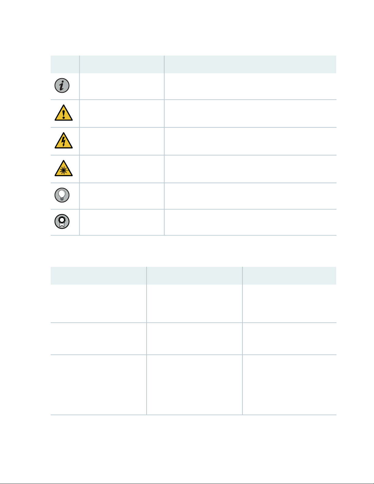
Table 1: Notice Icons
xv
DescriptionMeaningIcon
Indicates important features or instructions.Informational note
Caution
Indicates a situation that might result in loss of data or hardware
damage.
Alerts you to the risk of personal injury or death.Warning
Alerts you to the risk of personal injury from a laser.Laser warning
Indicates helpful information.Tip
Alerts you to a recommended use or implementation.Best practice
Table 2 on page xv defines the text and syntax conventions used in this guide.
Table 2: Text and Syntax Conventions
ExamplesDescriptionConvention
Fixed-width text like this
Italic text like this
Represents text that you type.Bold text like this
Represents output that appears on
the terminal screen.
Introduces or emphasizes important
•
new terms.
Identifies guide names.
•
Identifies RFC and Internet draft
•
titles.
To enter configuration mode, type
the configure command:
user@host> configure
user@host> show chassis alarms
No alarms currently active
A policy term is a named structure
•
that defines match conditions and
actions.
Junos OS CLI User Guide
•
RFC 1997, BGP Communities
•
Attribute
Page 16

Table 2: Text and Syntax Conventions (continued)
xvi
ExamplesDescriptionConvention
Italic text like this
Text like this
< > (angle brackets)
| (pipe symbol)
Represents variables (options for
which you substitute a value) in
commands or configuration
statements.
Represents names of configuration
statements, commands, files, and
directories; configuration hierarchy
levels; or labels on routing platform
components.
variables.
Indicates a choice between the
mutually exclusive keywords or
variables on either side of the symbol.
The set of choices is often enclosed
in parentheses for clarity.
Configure the machine’s domain
name:
[edit]
root@# set system domain-name
domain-name
To configure a stub area, include
•
the stub statement at the [edit
protocols ospf area area-id]
hierarchy level.
The console port is labeled
•
CONSOLE.
stub <default-metric metric>;Encloses optional keywords or
broadcast | multicast
(string1 | string2 | string3)
# (pound sign)
[ ] (square brackets)
Indention and braces ( { } )
; (semicolon)
GUI Conventions
Indicates a comment specified on the
same line as the configuration
statement to which it applies.
Encloses a variable for which you can
substitute one or more values.
Identifies a level in the configuration
hierarchy.
Identifies a leaf statement at a
configuration hierarchy level.
rsvp { # Required for dynamic MPLS
only
community name members [
community-ids ]
[edit]
routing-options {
static {
route default {
nexthop address;
retain;
}
}
}
Page 17
Table 2: Text and Syntax Conventions (continued)
xvii
ExamplesDescriptionConvention
Bold text like this
> (bold right angle bracket)
Represents graphical user interface
(GUI) items you click or select.
Separates levels in a hierarchy of
menu selections.
In the Logical Interfaces box, select
•
All Interfaces.
To cancel the configuration, click
•
Cancel.
In the configuration editor hierarchy,
select Protocols>Ospf.
Documentation Feedback
We encourage you to provide feedback so that we can improve our documentation. You can use either
of the following methods:
Online feedback system—Click TechLibrary Feedback, on the lower right of any page on the Juniper
•
Networks TechLibrary site, and do one of the following:
Click the thumbs-up icon if the information on the page was helpful to you.
•
Click the thumbs-down icon if the information on the page was not helpful to you or if you have
•
suggestions for improvement, and use the pop-up form to provide feedback.
E-mail—Send your comments to techpubs-comments@juniper.net. Include the document or topic name,
•
URL or page number, and software version (if applicable).
Requesting Technical Support
Technical product support is available through the Juniper Networks Technical Assistance Center (JTAC).
If you are a customer with an active Juniper Care or Partner Support Services support contract, or are
Page 18

covered under warranty, and need post-sales technical support, you can access our tools and resources
online or open a case with JTAC.
JTAC policies—For a complete understanding of our JTAC procedures and policies, review the JTAC User
•
Guide located at https://www.juniper.net/us/en/local/pdf/resource-guides/7100059-en.pdf.
Product warranties—For product warranty information, visit https://www.juniper.net/support/warranty/.
•
JTAC hours of operation—The JTAC centers have resources available 24 hours a day, 7 days a week,
•
365 days a year.
Self-Help Online Tools and Resources
For quick and easy problem resolution, Juniper Networks has designed an online self-service portal called
the Customer Support Center (CSC) that provides you with the following features:
Find CSC offerings: https://www.juniper.net/customers/support/
•
Search for known bugs: https://prsearch.juniper.net/
•
xviii
Find product documentation: https://www.juniper.net/documentation/
•
Find solutions and answer questions using our Knowledge Base: https://kb.juniper.net/
•
Download the latest versions of software and review release notes:
•
https://www.juniper.net/customers/csc/software/
Search technical bulletins for relevant hardware and software notifications:
•
https://kb.juniper.net/InfoCenter/
Join and participate in the Juniper Networks Community Forum:
•
https://www.juniper.net/company/communities/
Create a service request online: https://myjuniper.juniper.net
•
To verify service entitlement by product serial number, use our Serial Number Entitlement (SNE) Tool:
https://entitlementsearch.juniper.net/entitlementsearch/
Creating a Service Request with JTAC
You can create a service request with JTAC on the Web or by telephone.
Visit https://myjuniper.juniper.net.
•
Call 1-888-314-JTAC (1-888-314-5822 toll-free in the USA, Canada, and Mexico).
•
For international or direct-dial options in countries without toll-free numbers, see
https://support.juniper.net/support/requesting-support/.
Page 19

1
CHAPTER
Overview
System Overview | 20
MX5, MX10, MX40, and MX80 Chassis | 26
MX5, MX10, MX40, and MX80 Power System | 35
MX5, MX10, MX40, and MX80 Host Subsystem | 49
MX5, MX10, MX40, and MX80 Interface Modules | 50
Page 20
System Overview
IN THIS SECTION
MX5, MX10, MX40, and MX80 Router Overview | 20
MX5, MX10, MX40, and MX80 Router Models | 23
MX5, MX10, MX40, and MX80 Hardware Components and CLI Terminology | 25
MX5, MX10, MX40, and MX80 Router Overview
20
IN THIS SECTION
Benefits of the MX5, MX10, MX40, and MX80 Router | 20
MX5, MX10, MX40, and MX80 Hardware Overview | 21
The Juniper Networks MX5, MX10, MX40, and MX80 Universal Routing Platforms are Ethernet-optimized
edge routers that provide both switching and carrier-class Ethernet routing. The MX5, MX10, MX40, and
MX80 routers run Junos operating system (Junos OS), enabling a wide range of business and residential
applications and services, including high-speed transport and virtual private network (VPN) services,
next-generation broadband multiplay services, and high-volume Internet data center internetworking.
Each router provides full duplex, high-density Ethernet interfaces and high- capacity switching throughput
and uses the Junos Trio chipset for increased scalability of L2/L3 packet forwarding, buffering, and queuing.
Benefits of the MX5, MX10, MX40, and MX80 Router
System Capacity—The MX80, MX40, MX10, and MX5 routers are software upgradeable from 20 Gbps
•
to 80 Gbps. These platforms have up to four Modular Interface Card (MIC) slots and two fixed 10-Gigabit
Ethernet interfaces for connecting to the network.
Always-on infrastructure base—MX Series routers ensure network and service availability with a broad
•
set of multilayered physical, logical, and protocol-level resiliency aspects. Junos OS Virtual Chassis
technology on MX Series routers supports chassis-level redundancy and enables you to manage two
routers as a single element. Multichassis link aggregation group (MC-LAG) implementation supports
stateful chassis, card, and port redundancy.
Page 21

Application-Aware Networking—On MX Series routers you can use deep packet inspection to detect
•
applications, and by using the user-defined policies, you can determine traffic treatment for each
application. This feature enables highly customized and differentiated services at scale.
Programmable Chipset—The chipset implemented in the MX Series routers has a programmable
•
forwarding data structure that allows fast microcode changes in the hardware itself, and a programmable
lookup engine that allows inline service processing. the chip’s programmable QoS engine supports coarse
and fine-grained queuing to address the requirements of core, edge, and aggregation use cases.
Junos Continuity and Unified In-Service Software Upgrade (Unified ISSU)—With the Junos continuity
•
plug-in package, you can perform a smooth upgrade when new hardware is installed in your MX Series
router.
Unified in-service software upgrade (unified ISSU) enables software upgrades and changes without
disrupting network traffic.
Junos Telemetry Interface—Using the Junos telemetry interface data, you can stream component-level
•
data to monitor, analyze, and enhance the performance of the network. Analytics derived from this
streaming telemetry can identify current and trending congestion, resource utilization, traffic volume,
and buffer occupancy.
21
Integrated Hardware-Based Timing—You do not need to use external clocks because MX Series routers
•
support highly scalable and reliable hardware-based timing, including Synchronous Ethernet for frequency,
and the Precision Time Protocol (PTP) for frequency and phase synchronization. Synchronous Ethernet
and PTP can be combined in a hybrid mode to achieve a high level of frequency (10 ppb) and phase (<1.5
uS) accuracy.
MX5, MX10, MX40, and MX80 Hardware Overview
The routers each contain a built-in Routing Engine and one Packet Forwarding Engine. The Packet
Forwarding Engine has two “pseudo” Flexible PIC Concentrators (FPC 0 and FPC1). Because there is no
switching fabric, the single Packet Forwarding Engine takes care of both ingress and egress packet
forwarding.
The routers are compact and two rack units (U) tall. Several routers can be stacked in a single floor-to-ceiling
rack for increased port density per unit of floor space.
For scalable configuration options you can install a variety of Modular Interface Cards (MICs) in the two
front slots of the router, and the optional Multiservices MIC can be installed in the rear slot. Software
licenses allow you to upgrade from one router to another without a hardware upgrade. The ports are
restricted based on the router’s associated license as follows:
Page 22
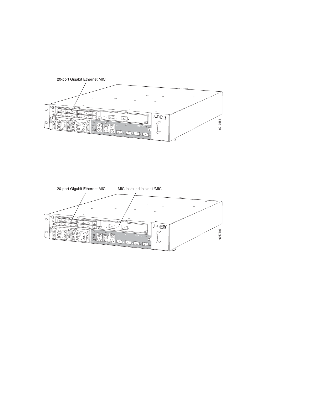
MX5 router: Allows usage of the MIC slot labeled 1/MIC 0, which comes prepopulated with the Gigabit
g017585
MX5-T
SYSOK
ONLINE
OFFLINE
RE
CONSOLE
ETHERNET
A
B
AUX
USB
EXTCLK
FAN
0/MIC 0
PS1
0
1
2
3
LINK
LINK
LINK
LINK
20-port Gigabit Ethernet MIC
g017586
SYSOK
ONLINE
OFFLINE
RE
CONSOLE
ETHERNET
A
B
AUX
USB
EXTCLK
FAN
0/MIC 0
PS1
0
1
2
3
LINK
LINK
LINK
LINK
MX10-T
20-port Gigabit Ethernet MIC
MIC installed in slot 1/MIC 1
•
Ethernet MIC with SFP.
Figure 1: MX5 Router
MX10 router: Allows usage of the MIC slot labeled 1/MIC 0, which comes prepopulated with the Gigabit
•
Ethernet MIC with SFP and the second MIC slot labeled 1/MIC 1.
22
Figure 2: MX10 Router
MX40 router: Allows usage of the front MIC slots and ports 0 and 1 of the built-in 10-Gigabit Ethernet
•
MIC (labeled 0/MIC 0).
Page 23
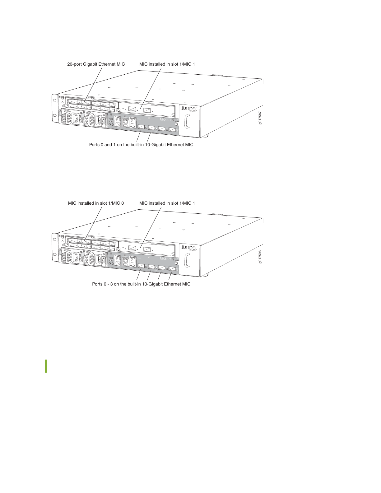
Figure 3: MX40 Router
g017587
SYSOK
ONLINE
OFFLINE
RE
CONSOLE
ETHERNET
A
B
AUX
USB
EXTCLK
FAN
0/MIC 0
PS1
0
1
2
3
LINK
LINK
LINK
LINK
MX40-T
20-port Gigabit Ethernet MIC
MIC installed in slot 1/MIC 1
Ports 0 and 1 on the built-in 10-Gigabit Ethernet MIC
g017596
SYSOK
ONLINE
OFFLINE
RE
CONSOLE
ETHERNET
A
B
AUX
USB
EXTCLK
FAN
0/MIC 0
PS1
0
1
2
3
LINK
LINK
LINK
LINK
MX80-T
MIC installed in slot 1/MIC 0
MIC installed in slot 1/MIC 1
Ports 0 - 3 on the built-in 10-Gigabit Ethernet MIC
MX80 router: Allows usage of all MIC slots (front and back) and all four ports of the built-in 10-Gigabit
•
Ethernet MIC (labeled 0/MIC 0).
Figure 4: MX80 Router
23
A fixed version of the MX80 router (model number: MX80-48T) has 48 fixed 10/100/1000Base-T RJ45
ports in place of the MIC slots.
For a list of MICs supported on the MX5, MX10, MX40, and modular MX80 routers, see “MICs Supported
by MX Series Routers” on page 53 in the MX Series Interface Module Reference.
MX5, MX10, MX40, and MX80 Router Models
“MX5, MX10, MX40, and MX80 Routers Physical Specifications” on page 71
The MX5, MX10, MX40, and MX80 routers are available in different models. The tables below list the
various MX5, MX10, MX40 and MX80 router models available and provide a brief description of each
base units.
Table 3 on page 24 lists the different MX5 router models available.
Page 24

Table 3: MX5 Router Models
DescriptionModel Number
DC chassisMX5-T-DC
AC chassisMX5-T-AC
Table 4 on page 24 lists the different MX10 router models available.
Table 4: MX10 Router Models
DescriptionModel Number
DC chassisMX10-T-DC
AC chassisMX10-T-AC
24
Table 5 on page 24 lists the different MX40 router models available.
Table 5: MX40 Router Models
DescriptionModel Number
DC chassisMX40-T-DC
AC chassisMX40-T-AC
Table 6 on page 24 lists the different MX80 router models available.
Table 6: MX80 Router Models
DescriptionModel Number
MX80 AC chassisMX80-AC
MX80 DC chassisMX80-DC
MX80 AC chassis with timing supportMX80-T-AC
MX80 DC chassis with timing supportMX80-T-DC
MX80 AC chassis with PTP (IEEE 1588v2) supportMX80-P-AC
MX80 DC chassis with PTP (IEEE 1588v2) supportMX80-P-DC
Page 25
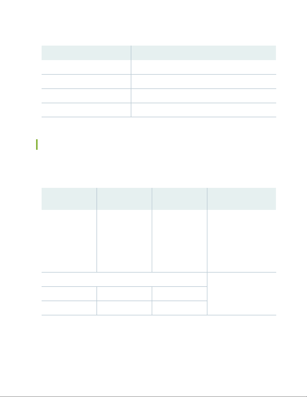
Table 6: MX80 Router Models (continued)
DescriptionModel Number
MX80 fixed 48 GE port AC chassisMX80-48T-AC
MX80 fixed 48 GE port DC chassisMX80-48T-DC
MX80 fixed 48 GE port AC chassis with timing supportMX80-T-48T-AC
MX80 fixed 48 GE port DC chassis with timing supportMX80-T-48T-DC
MX5, MX10, MX40, and MX80 Hardware Components and CLI Terminology
The MX5, MX10, MX40, and MX80 routers support the components in Table 7 on page 25, listed in
alphabetic order.
25
Table 7: MX5, MX10, MX40, and MX80 Routers Hardware Components and CLI Terminology
Hardware Model
NumberComponent
N/AChassis
Cooling system, including fan trays and air filters
MX5
•
MX10
•
MX40
•
MX80
•
MX80–P
•
MX80–T
•
MX80–48T
•
N/AFLTR-KIT-MX80Air filter kit
Fan TrayFANTRAY-MX80Fan tray
DescriptionCLI Name
“MX5, MX10, MX40, and MX80
Chassis Description” on page 27
MX5, MX10, MX40, and MX80
Cooling System Description
Page 26
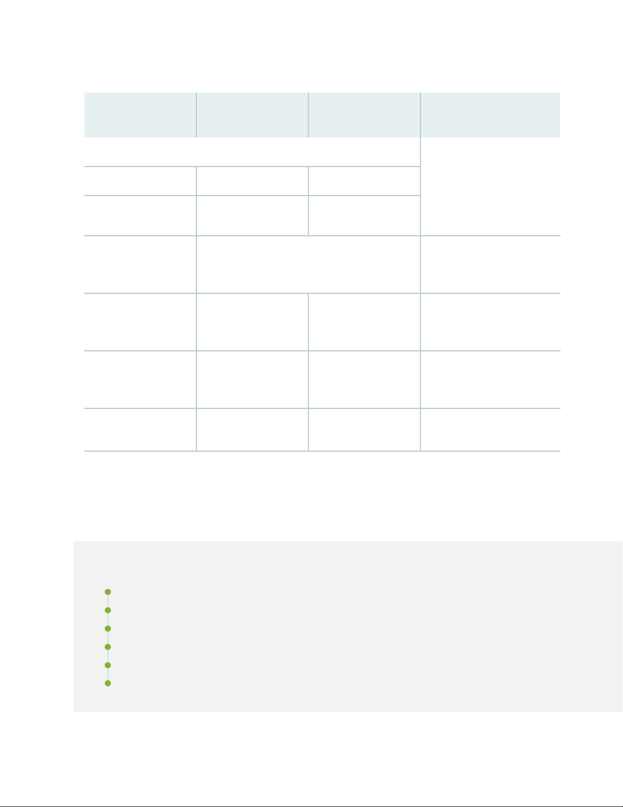
Table 7: MX5, MX10, MX40, and MX80 Routers Hardware Components and CLI Terminology (continued)
Hardware Model
NumberComponent
DescriptionCLI Name
26
Power system components
Power supply
Transceiver
AC: PWR-MX80-AC
•
DC: PWR-MX80-DC
•
See MX Series Interface Module Reference.MIC
Module Reference.
N/APWR-BLANK-MX80Power blank cover
PEM
FPCN/A (built-in)MPC
Routing EngineN/A (built-in)Routing Engine
XcvrSee MX Series Interface
“MX5, MX10, MX40, and MX80
Power System Description” on
page 36
“MX5, MX10, MX40, and MX80
Modular Interface Card
Description” on page 50
“MX5, MX10, MX40, and MX80
Modular Interface Card
Description” on page 50
“MX5, MX10, MX40, and MX80
Routing Engine Description” on
page 49
MX5, MX10, MX40, and MX80 Chassis
IN THIS SECTION
MX5, MX10, MX40, and MX80 Chassis Description | 27
MX5, MX10, MX40, and MX80 Baseboard Description | 29
MX5, MX10, MX40, and MX80 Cable Management Bracket Description | 30
MX5, MX10, MX40, and MX80 Front Panel Description | 31
Alarm LEDs on the MX5, MX10, MX40, and MX80 Front Panel | 33
Component LEDs on the MX5, MX10, MX40, and MX80 Front Panel | 34
Page 27
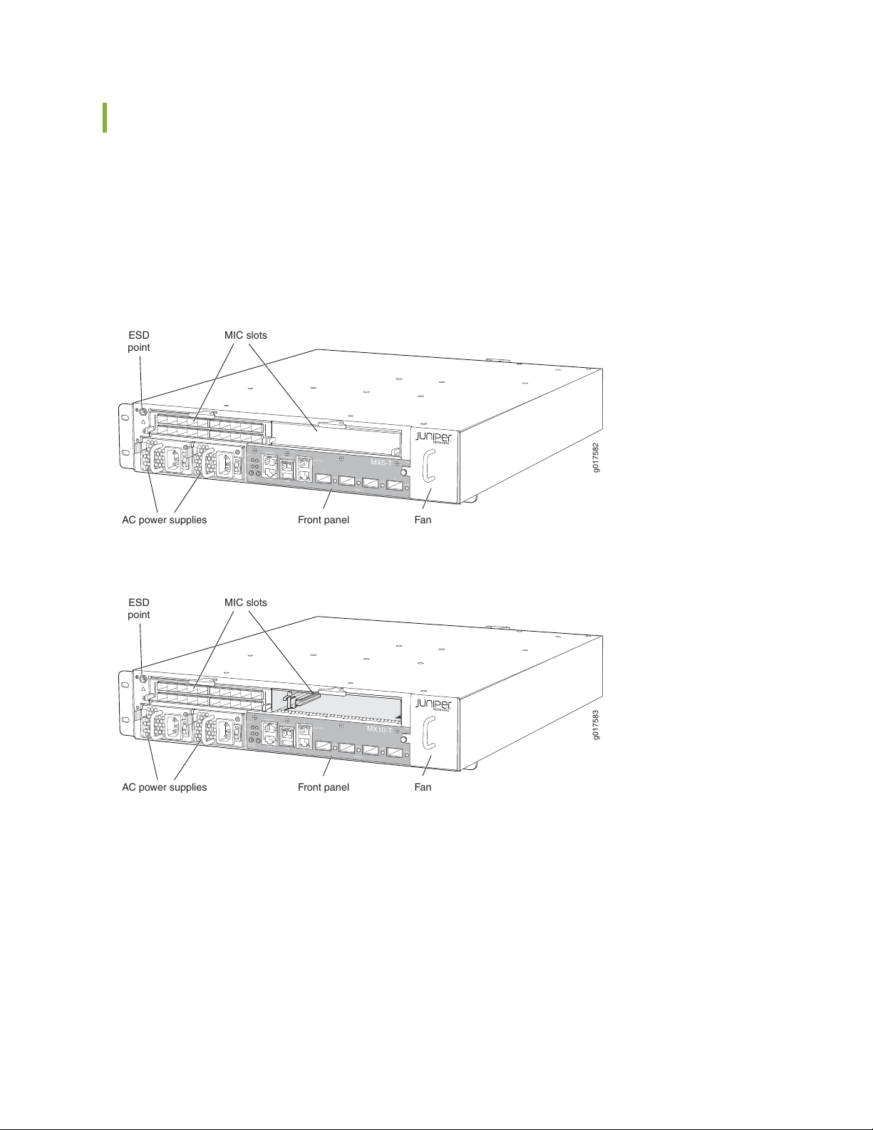
MX5, MX10, MX40, and MX80 Chassis Description
g017582
Front panel Fan
MIC slots
AC power supplies
ESD
point
MX5-T
SYSOK
ONLINE
OFFLINE
RE
CONSOLE
ETHERNET
A
B
AUX
USB
EXTCLK
FAN
0/MIC 0
PS1
0
1
2
3
LINK
LINK
LINK
LINK
g017583
Front panel Fan
MIC slots
AC power supplies
ESD
point
SYSOK
ONLINE
OFFLINE
RE
CONSOLE
ETHERNET
A
B
AUX
USB
EXTCLK
FAN
0/MIC 0
PS1
0
1
2
3
LINK
LINK
LINK
LINK
MX10-T
The router chassis is a rigid sheet metal structure that houses all the other router components (see
Figure 5 on page 27, Figure 6 on page 27, Figure 7 on page 28, Figure 8 on page 28, Figure 9 on page 28,
and Figure 10 on page 29). The chassis measures 3.5 in. (8.9 cm) high, 17.5 in. (44.5 cm) wide, and 23.46 in.
(59.6 cm) deep. The chassis installs in standard 600-mm deep (or larger) enclosed cabinets, 19-in. equipment
racks, or telco open-frame racks.
Figure 5: Front View of the MX5 Router
27
Figure 6: Front View of the MX10 Router
Page 28
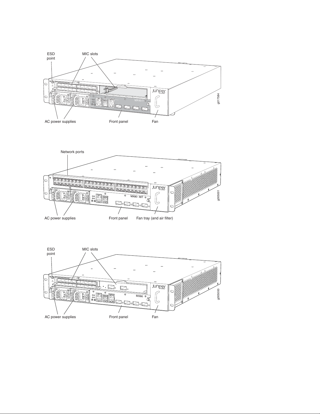
Figure 7: Front View of the MX40 Router
g017584
Front panel Fan
MIC slots
AC power supplies
ESD
point
SYSOK
ONLINE
OFFLINE
RE
CONSOLE
ETHERNET
A
B
AUX
USB
EXTCLK
FAN
0/MIC 0
PS1
0
1
2
3
LINK
LINK
LINK
LINK
MX40-T
g005001
Front panel Fan tray (and air filter)AC power supplies
Network ports
g005000
Front panel Fan
MIC slots
AC power supplies
ESD
point
Figure 8: Front View of the MX80 Router (Fixed Chassis)
28
Figure 9: Front View of the MX80 Router (Modular Chassis)
Page 29
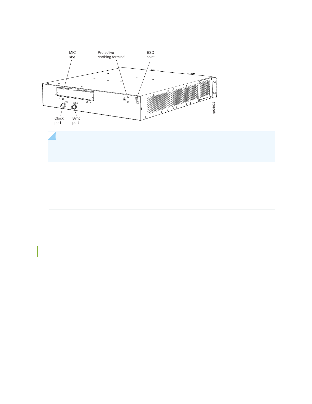
Figure 10: Rear View of the MX5, MX10, MX40, and MX80 Routers
g005002
CLOCK
SYNC
Clock
port
MIC
slot
Sync
port
ESD
point
Protective
earthing terminal
NOTE: The port labeled CLOCK provides 10 Mhz output. The port labeled SYNC provides 1
PPS output.
29
SEE ALSO
MX5, MX10, MX40, and MX80 Router Overview | 20
MX5, MX10, MX40, and MX80 Router Models | 23
MX5, MX10, MX40, and MX80 Routers Physical Specifications | 71
MX5, MX10, MX40, and MX80 Baseboard Description
The baseboard is located in the center of the chassis and forms the rear of the MIC card cage. The baseboard
is not replaceable. The MICs and power supplies install into the baseboard from the front of the chassis.
Data packets are transferred across the baseboard from the MIC to the Packet Forwarding Engine, and
from the Packet Forwarding Engine across the baseboard to the destination MIC.
The baseboard provides the following functions:
Powers on and powers off MICs
•
Controls clocking, system resets, and booting
•
Monitors and controls system functions, including fan speed, board power status, PDM status and
•
control, and the front panel
Provides interconnections to all the MICs within the chassis
•
Page 30

Baseboard Components
The baseboard consists of the following components:
Junos Trio chipset—Manages packet data memory, queuing systems, and performs packet lookup and
•
encapsulation.
MIC connectors for both built-in and replaceable MICs including a WAN interface for the built-in
•
10-Gigabit Ethernet MIC.
Intake and exhaust temperature sensors.
•
Circuits for chassis management and control.
•
Power circuits for the system components and Ethernet interfaces.
•
Routing Engine processor, which includes a 1.33-GHz CPU, and 2 GB of SDRAM.
•
2 4-GB NAND flash storage devices.
•
Packet Forwarding Engine processor, which includes a 1-GHz CPU, a system controller, and 1 GB of
•
SDRAM. Connects to the Routing Engine through a Gigabit Ethernet link.
30
Clock logic.
•
SEE ALSO
MX5, MX10, MX40, and MX80 Router Overview | 20
MX5, MX10, MX40, and MX80 Chassis Description | 27
MX5, MX10, MX40, and MX80 Routing Engine Description | 49
MX5, MX10, MX40, and MX80 Cable Management Bracket Description
The cable management bracket (see Figure 11 on page 31) consists of plastic dividers and installs on the
left side of the chassis. The cable management bracket allows you to route the cables outside the router
and away from the MICs.
Page 31

Figure 11: Cable Management Bracket for the MX5, MX10, MX40, and MX80 Routers
g005035
Cable
management
bracket
g005047
MX80-48T
ONLINE/
OFFLINE
Auxiliary
port
USB
port 10-Gigabit Ethernet MIC
Console
port
Ethernet
port
Routing
Engine
LED
Alarm
LEDs
System
status
LED
Reset
button
ONLINE/
OFFLINE
button
SEE ALSO
Installing the MX5, MX10, MX40, and MX80 Cable Management Bracket | 93
31
Connecting MX5, MX10, MX40, and MX80 Routers to Management Devices | 108
Connecting Interface Cables to MX5, MX10, MX40, and MX80 Routers
Maintaining Cables That Connect to MX5, MX10, MX40, and MX80 MICs | 137
MX5, MX10, MX40, and MX80 Front Panel Description
The front panel is located on the front of the router and allows you to view status and troubleshooting
information at a glance. The front panel contains LEDs for the router components, online/offline and reset
buttons, auxiliary and console ports, clocking ports, and ports for the 10-Gigabit Ethernet MIC.
Figure 12: Front Panel on the Fixed MX80 Router
Page 32

Figure 13: Front Panel on the Modular MX5, MX10, MX40, and MX80 Routers
g005046
ONLINE/
OFFLINE
Auxiliary
port
USB
port 10-Gigabit Ethernet MIC
Console
port
Ethernet
port
Clock
ports
Routing
Engine
LED
Alarm
LEDs
System
status
LED
Reset
button
ONLINE/
OFFLINE
button
Front Panel Components
Each front panel consists of the following components:
Interface ports—The AUX, CONSOLE, and ETHERNET ports provide access to management devices.
•
Each Routing Engine has one 1-Gbps Ethernet port for connecting to a management network and two
asynchronous serial ports—one for connecting to a console and one for connecting to a modem or other
auxiliary device.
32
Two ports for primary and secondary BITS clock input—Available on the modular MX80 chassis.
•
One fixed 10-Gigabit Ethernet MIC with four ports for uplink connections. For more information see
•
“MX5, MX10, MX40, and MX80 Modular Interface Card Description” on page 50.
USB port—Provides a removable media interface through which you can install the Junos OS manually.
•
(See Figure 14 on page 33.) Junos OS supports USB version 1.0.
Router online/offline button—Takes the router online or offline when pressed.
•
Reset button—Reboots the Routing Engine when pressed.
•
LEDs—Indicate component and system status and troubleshooting information at a glance.
•
Page 33

Figure 14: USB Memory Device in an MX5, MX10, MX40, and MX80 Router
g005008
USB Memory card
Alarm LEDs on the MX5, MX10, MX40, and MX80 Front Panel
33
Two alarm LEDs are located at the left of the front panel. The circular red LED lights to indicate a critical
condition that can result in a system shutdown. The triangular yellow LED lights to indicate a less severe
condition that requires monitoring or maintenance. Both LEDs can be lit simultaneously.
Table 8 on page 33 describes the alarm LEDs in more detail.
Table 8: Alarm LEDs on the MX5, MX10, MX40, and MX80 Front Panel
DescriptionStateColorShape
Red
Yellow
On
steadily
On
steadily
Critical alarm LED—Indicates a critical condition
that can cause the router to stop functioning.
Possible causes include component removal,
failure, or overheating.
Warning alarm LED—Indicates a serious but
nonfatal error condition, such as a maintenance
alert or a significant increase in component
temperature.
Page 34

Component LEDs on the MX5, MX10, MX40, and MX80 Front Panel
IN THIS SECTION
Link LEDs on the Front Panel | 34
Routing Engine LED on the Front Panel | 34
System LED on the Front Panel | 35
Link LEDs on the Front Panel
The front panel has a 10-Gigabit Ethernet MIC with four ports for uplink connections. Each port has one
LINK LED located to the right of the port. Table 9 on page 34 describes the link LEDs in more detail.
34
Table 9: Link LEDs on the Front Panel
DescriptionStateColorLabel
GreenLINK
steadily
Link is up.On
No link.Off–
Routing Engine LED on the Front Panel
One LED on the left side of the front panel indicates the status of the Routing Engine. The LED is located
below the RE label. Table 10 on page 34 describes the Routing Engine LED in more detail.
Table 10: Routing Engine LED on the Front Panel
DescriptionStateColorLabel
Routing Engine is transitioning online.BlinkingGreenLINK
Routing Engine has failed.BlinkingRed
Routing Engine is functioning normally.Off–
Page 35

System LED on the Front Panel
One LED on the left side of the front panel indicates the status of the router. The LED is located below
the SYS OK label. Table 11 on page 35 describes the system LED in more detail.
Table 11: System LED on the Front Panel
DescriptionStateColorLabel
35
GreenSYS OK
steadily
Routing Engine is functioning normally.On
Routing Engine is transitioning online.Off—
SEE ALSO
Troubleshooting Resources for MX5, MX10, MX40, and MX80 Routers | 154
Troubleshooting the MX5, MX10, MX40, and MX80 Fan Tray | 154
Troubleshooting the MX5, MX10, MX40, and MX80 MICs | 157
Troubleshooting the MX5, MX10, MX40, and MX80 Power Supplies | 158
MX5, MX10, MX40, and MX80 Power System
IN THIS SECTION
MX5, MX10, MX40, and MX80 Power System Description | 36
MX5, MX10, MX40, and MX80 Power Supply LED | 39
MX5, MX10, MX40, and MX80 Routers AC Power Specifications | 39
Power Consumption for an AC-Powered MX5, MX10, MX40, and MX80 Router | 40
AC Power Circuit Breaker Requirements for the MX5, MX10, MX40, and MX80 Router | 42
AC Power Cord Specifications for MX5, MX10, MX40, and MX80 Routers | 42
MX5, MX10, MX40, and MX80 Routers DC Power Specifications | 44
Power Consumption for a DC-Powered MX5, MX10, MX40, and MX80 Router | 44
DC Power Circuit Breaker Requirements for the MX5, MX10, MX40, and MX80 Routers | 46
Page 36

DC Power Source Cabling for MX5, MX10, MX40, and MX80 Routers | 47
DC Power Cable Specifications for MX5, MX10, MX40, and MX80 Routers | 47
MX5, MX10, MX40, and MX80 Power System Description
IN THIS SECTION
AC Power Supply Description | 37
DC Power Supply Description | 38
36
The MX5, MX10, MX40, and MX80 routers use either AC or DC power supplies (see Figure 15 on page 37
and Figure 16 on page 37). The router contains either one or two power supplies located at the front of
the chassis in slots PS0 and PS1 (right to left). Each power supply has a handle, an ejection lever, a power
switch, and a status LED. The power supplies connect to the baseboard, which distributes the different
output voltages produced by the power supplies to the router components, depending on their voltage
requirements. When two power supplies are present, they share power almost equally within a fully
populated system. If one power supply in a redundant configuration fails or is removed, the remaining
power supply assumes the entire electrical load without interruption. A single power supply provides the
maximum configuration with full power for as long as the router is operational. A second power supply
can be installed for redundancy. Each power supply is cooled by its own internal cooling system.
Redundant power supplies are hot-removable and hot-insertable. When you remove a power supply from
a router that uses only one power supply, the router might shut down depending on your configuration.
CAUTION: The router cannot be powered from AC and DC power supplies
simultaneously.
NOTE: Routers configured with only one power supply are shipped with a blank panel installed
over the power supply slot that is not populated.
Page 37

Figure 15: AC Power Supplies Installed in an MX5, MX10, MX40, and MX80 Router
g005011
AC power supplies
g005012
DC power supplies
Figure 16: DC Power Supplies Installed in an MX5, MX10, MX40, and MX80 Router
37
AC Power Supply Description
Each AC power supply weighs approximately 2.6 lb (1.18 kg) and consists of a handle, an ejection lever,
an AC appliance inlet, an AC input switch, a fan, and an LED to monitor the status of the power supply.
Figure 17 on page 38 shows the power supply.
Each inlet requires a dedicated AC power feed and a dedicated customer site circuit breaker. We recommend
that you use a minimum 15 A (110 VAC) customer site circuit breaker, or as required by local code.
Page 38

Figure 17: AC Power Supply
g005022
Ejector lever Status LED
Handle AC power
inlet
Power
switch
g005023
Ejector lever Status LED
Handle DC
terminal
block
Power
switch
WARNING: The router is pluggable type A equipment installed in a restricted-access
location. It has a separate protective earthing terminal (sized for SAE 10-32 ground
screws) provided on the chassis in addition to the grounding pin of the power supply
cord. This separate protective earthing terminal must be permanently connected to
earth.
38
DC Power Supply Description
Each DC power supply has a handle, an ejection lever, a power switch, a status LED, and a terminal block
that provides a single DC input (–48 VDC and return) that requires a dedicated customer site circuit breaker.
We recommend that you use a dedicated customer site circuit breaker rated for 13 A (–48 VDC) minimum,
or as required by local code. Figure 18 on page 38 shows the power supply.
Figure 18: DC Power Supply
Page 39

MX5, MX10, MX40, and MX80 Power Supply LED
Each power supply has a bi-color status LED located above the power switch on the power supply.
Table 12: Power Supply LED
DescriptionStateColor
39
Blue
steadily
Power supply is functioning normally.On
Power supply has failed.BlinkingRed
PEM is in offline mode.OfflineRed
MX5, MX10, MX40, and MX80 Routers AC Power Specifications
Table 13 on page 39 lists the AC power system electrical specifications.
Table 13: AC Power System Electrical Specifications
SpecificationItem
Operating range: 90 to 264 VACAC input voltage
50 to 60 Hz (nominal)AC input line frequency
AC system current rating
6 A @ 110 VAC (7 A maximum per inlet at 90 VAC) or
3 A @ 220 VAC
610 WAC system input power
Table 14 on page 39 lists the AC power supply electrical specifications.
Table 14: AC Power Supply Electrical Specifications
SpecificationItem
500 WMaximum output power
Operating range: 90 to 264 VAC (nominal)AC input voltage
50 to 60 Hz (nominal)AC input line frequency
Page 40

Table 14: AC Power Supply Electrical Specifications (continued)
SpecificationItem
6 A @ 110 VAC or 3 A @ 220 VAC maximumAC input current rating
SEE ALSO
AC Power Electrical Safety Guidelines and Warnings for MX5, MX10, MX40, and MX80 Routers | 212
Power Consumption for an AC-Powered MX5, MX10, MX40, and MX80 Router
40
To allow for future growth so that you can operate the router in any hardware configuration without
upgrading the power infrastructure, we recommend that you provision 6 A @ 110 VAC (660 W) or
3 A @ 220 VAC (660 W) for each input.
Table 15 on page 40 and Table 16 on page 41 list the power requirements for base AC-powered routers
operating under typical voltage conditions.
If you do not plan to provision 6 A @ 110 VAC (660 W) or 3 A @ 220 VAC (660 W) for each input, you
can use the information in Table 15 on page 40, Table 16 on page 41, and Table 17 on page 41 to calculate
the power consumption and thermal output for your hardware configuration.
Table 15: AC Base Router Power Requirements for the Fixed MX5, MX10, MX40, and MX80 Routers
Power Requirement
Power Requirement
(Watts)Fixed Chassis Configuration
10-Gigabit Ethernet XFPs, and fans running at high
speed
(Watts) with 85%
Efficiency
376 W320 WChassis running at high activity, with four
Page 41

Table 16: AC Base Router Power Requirements for the Modular MX5, MX10, MX40, and MX80 Routers
Power Requirement
Power Requirement
(Watts)Modular Chassis Configuration
10-Gigabit Ethernet XFPs, two MICs, and fans
running at high speed
MICs
(Watts) with 85%
Efficiency
365 W310 WChassis running at high activity, with four
282 W240 WChassis running at high activity without the two
Table 17 on page 41 lists the power requirements for various hardware components when the router is
operating under typical voltage conditions.
Table 17: Component Power Requirements
41
Power
Requirement
(Watts)Component
Power Requirement
(Watts) with 85%
Efficiency
41 W35 WMIC (generalized value)
These examples use generalized values per MIC. For exact MIC power requirements, see the MX Series
Interface Module Reference.
The following calculations show the typical power consumption for modular AC-powered routers @ 220 V
(includes 85% efficiency):
Active AC-powered router with one MIC:
•
Base router (high activity, with four 10-Gigabit Ethernet XFPs, and fans running at high speed) + 1 MIC =
282 W + 41 W = 323 W
Active AC-powered router with two MICs:
•
Base router (high activity, with four 10-Gigabit Ethernet XFPs, and fans running at high speed) + 2 MICs
282 W + 2(41 W)= 364 W
Example of calculating system thermal output:
•
Watts AC PEM * 3.41 = BTU/hr
500 W * 3.41 = 1,705 BTU/hr
Page 42

SEE ALSO
Maintaining the MX5, MX10, MX40, and MX80 Power Supplies | 139
Replacing an MX5, MX10, MX40, and MX80 AC Power Supply | 140
AC Power Circuit Breaker Requirements for the MX5, MX10, MX40, and MX80 Router
We recommend that you use a dedicated customer site circuit breaker rated for 15 A (110 VAC) minimum
or 10 A (220 VAC) minimum for each AC power feed, or as required by local code. Doing so enables you
to operate the router in any configuration without upgrading the power infrastructure.
AC Power Cord Specifications for MX5, MX10, MX40, and MX80 Routers
42
Each AC power supply has a single AC appliance inlet located on the power supply that requires a dedicated
AC power feed. Most sites distribute power through a main conduit that leads to frame-mounted power
distribution panels, one of which can be located at the top of the rack that houses the router. An AC power
cord connects each power supply to the power distribution panel.
You can order detachable AC power cords, each approximately 8 ft (2.5 m) long that supply AC power to
the router. The C13 appliance coupler end of the cord inserts into the AC appliance inlet coupler, type
C14 as described by International Electrotechnical Commission (IEC) standard 60320. The plug end of the
power cord fits into the power source receptacle that is standard for your geographic location.
Table 18 on page 42 provides specifications on the AC power cord provided for each country or region.
Table 18: AC Power Cord Specifications
Plug TypeElectrical SpecificationModel NumberCountry
AS/NZ 3112–1993250 VAC, 10 A, 50 HzCBL-JX-PWR-AUAustralia
250 VAC, 10 A, 50 HzCBL-JX-PWR-CHChina
and United Kingdom)
GB2099.1 1996 and
GB1002 1996 (CH1-10P)
CEE (7) VII250 VAC, 10 A, 50 HzCBL-JX-PWR-EUEurope (except Italy
CEI 23–16/VII250 VAC, 10 A, 50 HzCBL-JX-PWR-ITItaly
JIS 8303125 VAC, 12 A, 50 Hz or 60 HzCBL-JX-PWR-JPJapan
Page 43
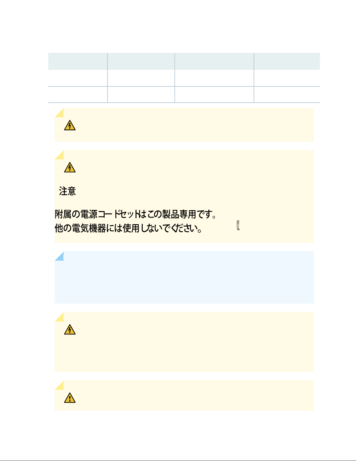
Table 18: AC Power Cord Specifications (continued)
WARNING: The AC power cord for the router is intended for use with the router only
and not for any other use.
WARNING: The attached power cable is only for this product. Do not use the cable
for another product. Translation in Japanese follows:
43
Plug TypeElectrical SpecificationModel NumberCountry
NEMA 5-15125 VAC, 10 A, 60 HzCBL-JX-PWR-USNorth America
BS 1363A250 VAC, 10 A, 50 HzCBL-JX-PWR-UKUnited Kingdom
NOTE: In North America, AC power cords must not exceed approximately 14.75 ft (4.5 m) in
length, to comply with National Electrical Code (NEC) Sections 400-8 (NFPA 75, 5-2.2) and
210-52, and Canadian Electrical Code (CEC) Section 4-010(3). You can order AC power cords
that are in compliance.
WARNING: The router is pluggable type A equipment installed in a restricted-access
location. It has a separate protective earthing terminal (sized for SAE 10-32 ground
screws) provided on the chassis in addition to the grounding pin of the power supply
cord. This separate protective earthing terminal must be permanently connected to
earth.
CAUTION: Power cords and cables must not block access to device components or
drape where people could trip on them.
Page 44

MX5, MX10, MX40, and MX80 Routers DC Power Specifications
Table 19 on page 44 lists the DC power system electrical specifications.
Table 19: DC Power System Electrical Specifications
SpecificationItem
Operating range: –40 to –72 VDCDC input voltage
13 A @ –48 VDC (maximum) (625 W DC)DC system input current
rating
13 A @ –48 VDC (625 W DC)DC system input power
Table 20 on page 44 lists the DC power supply electrical specifications.
Table 20: DC Power Supply Electrical Specifications
44
SpecificationItem
500 WMaximum output power
DC input voltage
Minimum: –40 VDC
Nominal: –48 VDC, –60 VDC
Operating range: –40 to –72 VDC
13 A @ –48 VDCDC input current rating
Power Consumption for a DC-Powered MX5, MX10, MX40, and MX80 Router
To allow for future growth so that you can operate the router in any hardware configuration without
upgrading the power infrastructure, we recommend that you provision at least 13 A @ –48 VDC for each
input.
Table 21 on page 45 and Table 22 on page 45 list the power requirements for base DC-powered routers
operating under typical voltage conditions.
Page 45

If you do not plan to provision at least 13 A @ –48 VDC per input, you can use the information in
Table 21 on page 45, Table 22 on page 45, and Table 23 on page 45 to calculate the power consumption
@ –48 VDC and thermal output for your hardware configuration.
Table 21: DC-Powered Base Router Power Requirements for the Fixed MX80 Router
Current
Power
Requirement
(Watts)Fixed Chassis Configuration
Requirement
(Amps @
–48 VDC)
45
320 WChassis running at high activity, with four 10-Gigabit Ethernet XFPs, and fans
running at high speed
6.7 A
(approximate)
Table 22: DC-Powered Base Router Power Requirements for the MX5, MX10, MX40, and Modular MX80
Router
Current
Power
Requirement
(Watts)Modular Chassis Configuration
310 WChassis running at high activity, with four 10-Gigabit Ethernet XFPs, two MICs,
and fans running at high speed
Requirement
(Amps @
–48 VDC)
6.5 A
(approximate)
Table 23 on page 45 lists the power requirements for various hardware components when the router is
operating under typical voltage conditions.
Table 23: Component Power Requirements for DC-Powered Routers
Current
Requirement
Power Requirement
(Watts)Component
(Amps @
–48 VDC)
0.73 A35 WMIC (generalized value)
These examples show how to calculate typical power consumption for your DC-powered router
configuration. The examples use generalized values for MICs. For exact MIC power requirements, see the
MX Series Interface Module Reference.
Typical power consumption for modular DC-powered routers:
Active DC-powered router with one MIC:
•
Page 46

Base router (high activity, with four 10-Gigabit Ethernet XFPs, and fans running at high speed) + 1 MIC =
5 A + 0.73 A = 5.73 A @ –48 VDC = 275 W DC
Active DC-powered router with two MICs:
•
Base router (high activity, with four 10-Gigabit Ethernet XFPs, and fans running at high speed) + 2 MICs
5 A + 2(0.73 A) = 6.46 A @ –48 VDC = 310 W DC
Input current from a DC source other than –48 VDC (based on maximum configuration; applies to DC
•
power supply only):
(–54 VDC input) * (input current X) = (–48 VDC input) * (input current Y)
54 * X = 48 * 13 A
X = 48 * 13 A/54 = 11.5 A
Example of calculating system thermal output:
•
46
Watts DC * 3.41 = BTU/hr
500 * 3.41 = 1,705 BTU/hr
DC Power Circuit Breaker Requirements for the MX5, MX10, MX40, and MX80 Routers
Each DC power supply has a single DC input (–48 VDC and return) that requires a dedicated circuit breaker.
We recommend that you use a dedicated customer site circuit breaker rated for 13 A (–48 VDC) minimum,
or as required by local code. Doing so enables you to operate the router in any configuration without
upgrading the power infrastructure.
If you plan to operate a DC-powered router at less than the maximum configuration and do not provision
a 13 A (–48 VDC) circuit breaker, we recommend that you provision a dedicated customer site circuit
breaker for each DC power supply rated for at least 125 percent of the continuous current that the system
draws at –48 VDC.
Page 47

DC Power Source Cabling for MX5, MX10, MX40, and MX80 Routers
The DC power supply in PS0 must be powered by a dedicated power feed derived from feed A, and the
DC power supply in PS1 must be powered by a dedicated power feed derived from feed B. This configuration
provides the commonly deployed A/B feed redundancy for the system.
CAUTION: You must ensure that power connections maintain the proper polarity.
The power source cables might be labeled (+) and (–) to indicate their polarity. There
is no standard color coding for DC power cables. The color coding used by the external
DC power source at your site determines the color coding for the leads on the power
cables that attach to the terminal studs on each power supply.
WARNING: For field-wiring connections, use copper conductors only.
47
CAUTION: Power cords and cables must not block access to device components or
drape where people could trip on them.
DC Power Cable Specifications for MX5, MX10, MX40, and MX80 Routers
IN THIS SECTION
DC Power Cable Lug Specifications | 47
DC Power Cable Specifications | 48
DC Power Cable Lug Specifications
The accessory box shipped with the router includes the cable lugs that attach to the terminal of each
power supply.
Page 48

Figure 19: DC Power Cable Lug
g000100
All m ea su remen t s in inch es
.90
.68
0 .25
.14 dia .
.170 m ax.
wi re diam et er
(insu la tion)
CAUTION: Before router installation begins, a licensed electrician must attach a cable
lug to the grounding and power cables that you supply. A cable with an incorrectly
attached lug can damage the router.
DC Power Cable Specifications
48
You must supply four DC power cables that meet the following specifications: 16-AWG (1.3 mm2), minimum
60° C wire, or as required by the local code.
SEE ALSO
MX5, MX10, MX40, and MX80 Power System Description | 36
Maintaining the MX5, MX10, MX40, and MX80 Power Supplies | 139
Replacing an MX5, MX10, MX40, and MX80 DC Power Supply | 144
MX5, MX10, MX40, and MX80 DC Power Electrical Safety Guidelines | 219
MX5, MX10, MX40, and MX80 Routers DC Power Specifications | 44
Power Consumption for a DC-Powered MX5, MX10, MX40, and MX80 Router | 44
DC Power Circuit Breaker Requirements for the MX5, MX10, MX40, and MX80 Routers | 46
DC Power Source Cabling for MX5, MX10, MX40, and MX80 Routers | 47
Page 49

MX5, MX10, MX40, and MX80 Host Subsystem
IN THIS SECTION
MX5, MX10, MX40, and MX80 Routing Engine Description | 49
MX5, MX10, MX40, and MX80 Routing Engine LED | 49
MX5, MX10, MX40, and MX80 Routing Engine Description
The Routing Engine is built-in on the MX5, MX10, MX40, and MX80 baseboard and cannot be replaced.
The Routing Engine consists of the following components:
49
Processor—Runs Junos OS to maintain the router's routing tables and routing protocols.
•
DRAM—Buffers incoming packets and provides storage for the routing and forwarding tables and for
•
other Routing Engine processes. To view the amount of DRAM installed on your router, issue the show
chassis routing-engine command.
NAND flash—Provides primary storage for software images, configuration files, and microcode.
•
SEE ALSO
Maintaining the MX5, MX10, MX40, and MX80 Routing Engine | 116
show chassis routing-engine
MX5, MX10, MX40, and MX80 Routing Engine LED
The Routing Engine LED appears on the left of the front panel and is labeled RE. For more information
see “Component LEDs on the MX5, MX10, MX40, and MX80 Front Panel” on page 34.
Page 50

MX5, MX10, MX40, and MX80 Interface Modules
IN THIS SECTION
MX5, MX10, MX40, and MX80 Modular Interface Card Description | 50
MICs Supported by MX Series Routers | 53
MX5, MX10, MX40, and MX80 Port and Interface Numbering | 64
MX5, MX10, MX40, and MX80 Modular Interface Card LEDs | 67
MX5, MX10, MX40, and MX80 Modular Interface Card Description
50
IN THIS SECTION
Front-Pluggable MICs | 51
Fixed (Built-in) MICs | 51
Modular Interface Cards (MICs) provide the physical connections to various network media types. MICs
receive incoming packets from the network and transmit outgoing packets to the network. During this
process, each MIC performs framing and high-speed signaling for its media type. Before transmitting
outgoing data packets through the MIC interfaces, the router encapsulates the packets received.
On the fixed MX80 chassis, the MICs come preinstalled and cannot be replaced.
On the modular MX5, MX10, MX40, and MX80 chassis, you can install a variety of MICs in the two front
slots of the router, and the optional Multiservices MIC can be installed in the rear slot.
Page 51

Figure 20: MICs Installed in an MX5, MX10, MX40, and MX80 Router
g005025
The MX5, MX10, MX40, and MX80 routers support the following types of MICs:
Front-Pluggable MICs
You can install and remove MICs in the MX5, MX10, MX40, and modular MX80 chassis. The MIC slots
are labeled 1/MIC 0 and 1/MIC 1. Each MIC slot has an ejector handle located above the MIC slot.
51
You can install MICs of different media types as long as the router supports those MICs. For complete
specifications, see “MICs Supported by MX Series Routers” on page 53.
Fixed (Built-in) MICs
Built-in 10-Gigabit Ethernet MIC
The built-in 10-Gigabit Ethernet MIC is fixed on the MX5, MX10, MX40, and MX80 routers. The MIC is
labeled 0/MIC 0 and is located on the front panel. The built-in 10-Gigabit Ethernet MIC has the following
components:
Hardware features:
Four 10-Gigabit Ethernet ports labeled 0 through 3, left to right.
•
High-performance throughput on each port at speeds up to 10 Gbps
•
Line-rate on all four 10-Gigabit Ethernet ports
•
LAN-PHY mode at 10.3125 Gbps
•
WAN-PHY mode at 9.953 Gbps
•
Maximum transmission units (MTUs) of up to 9192 bytes
•
Link LED, one green per port. For more information, see “Component LEDs on the MX5, MX10, MX40,
•
and MX80 Front Panel” on page 34.
Page 52

Software features:
Configurable LAN-PHY and WAN-PHY mode options
•
Synchronous Ethernet support
•
Optical diagnostics and related alarms
•
Virtual Router Redundancy Protocol (VRRP) support
•
IEEE 802.1Q virtual LANs (VLANs) support
•
Remote monitoring (RMON) EtherStats
•
Source MAC learning
•
MAC accounting and policing—Dynamic local address learning of source MAC addresses
•
Flexible Ethernet encapsulation
•
Multiple tag protocol identifiers (TPID)
•
Cables and connectors:
52
Duplex LC/PC connector (Rx and Tx)
•
Fiber-optic 10-gigabit small form-factor pluggable (XFP) transceivers:
•
Connector: Duplex LC/PC (Rx and Tx)
•
10GBASE-E (model number: XFP-10G-E-OC192-IR2)
•
10GBASE-L (model number: XFP-10G-L-OC192-SR1)
•
10GBASE-S (model number: XFP-10G-S)
•
10GBASE-Z (model number: XFP-10G-Z-OC192-LR2)
•
Optical interface specifications—see the Hardware Compatibility Tool at https://apps.juniper.net/hct
DWDM Tunable XFP transceivers:
•
Connector: Duplex LC/PC (Rx and Tx)
•
10GBASE-ZR (model number: XFP-10G-CBAND-T50-ZR)
•
DWDM supported wavelengths—see 10-Gigabit Ethernet DWDM Transceiver (XFP-10G-CBAND-T50-ZR)
Wavelengths
NOTE: XFP-10G-CBAND-T50-ZR is supported in Junos 11.2R2 and later
Optical interface specifications—see the Hardware Compatibility Tool at https://apps.juniper.net/hct
Page 53

Built-in Tri-Rate MIC
The built-in 48-port Tri-Rate MIC is available only on the fixed MX80 chassis (MX80-48T) and is not
replaceable. The built-in Tri-Rate MIC has the following components:
48 autonegotiating 10Base-T, 100Base-TX, or 1000Base-T Megabit Ethernet ports.
•
Autonegotiation between Gigabit Ethernet circuit partners.
•
Maximum transmission units (MTUs) of up to 9192 bytes.
•
Connector: Four-pair, Category 5 shielded twisted-pair connectivity through an RJ-45 connector.
•
Pinout: MDI/MDI-X.
•
Maximum distance: 328 ft (100 m).
•
Link LED, one green per port. For more information, see “MX5, MX10, MX40, and MX80 Modular
•
Interface Card LEDs” on page 67.
53
SEE ALSO
Maintaining the MX5, MX10, MX40, and MX80 MICs | 126
Troubleshooting the MX5, MX10, MX40, and MX80 MICs | 157
Replacing an MX5, MX10, MX40, and MX80 MIC | 127
MICs Supported by MX Series Routers
The following tables list the first supported Junos OS release for the MX Series.
Table 24 on page 54 lists the first supported Junos OS release for MICs on MX240, MX480, MX960,
•
and MX2008 routers.
Table 25 on page 56 lists the first supported Junos OS release for MICs on MX2010 and MX2020
•
routers.
Table 26 on page 59 list the first supported Junos OS release for MICs on MX5, MX10, and MX40
•
routers.
Table 27 on page 61 lists the first supported Junos OS release for MICs on MX80 and MX104 routers.
•
Table 28 on page 63 lists the first supported Junos OS release for MICs on MX10003 router.
•
Page 54

Table 24: MICs Supported by MX240, MX480, MX960 and MX2008 Routers
MX240,
MX480, and
MX960 RoutersPortsMIC Model NumberMIC Name
ATM
DS3/E3
54
MX2008
Routers
15.1F712.18MIC-3D-8OC3-2OC12-ATMATM MIC with SFP
DS3/E3 MIC
Circuit Emulation
Emulation MIC
Gigabit Ethernet
(E)
256b-AES MACsec
10-Gigabit Ethernet
XFP
15.1F711.48MIC-3D-8DS3-E3,
MIC-3D-8CHDS3-E3-B
15.1F712.316MIC-3D-16CHE1-T1-CEChannelized E1/T1 Circuit
15.1F710.120MIC-3D-20GE-SFPGigabit Ethernet MIC with SFP
15.1F713.320MIC-3D-20GE-SFP-EGigabit Ethernet MIC with SFP
-18.320MIC-MACSEC-20GEGigabit Ethernet MIC with
15.1F710.22MIC-3D-2XGE-XFP10-Gigabit Ethernet MICs with
XFP
SFP+ (10 Ports)
SFP+ (24 Ports)
with SFP+ (24 Ports)
15.1F710.14MIC-3D-4XGE-XFP10-Gigabit Ethernet MICs with
15.1F712.310MIC3-3D-10XGE-SFPP10-Gigabit Ethernet MIC with
15.1F7-24MIC6-10G10-Gigabit Ethernet MIC with
15.1F7-24MIC6-10G-OTN10-Gigabit Ethernet OTN MIC
Page 55

Table 24: MICs Supported by MX240, MX480, MX960 and MX2008 Routers (continued)
MX240,
MX480, and
MX960 RoutersPortsMIC Model NumberMIC Name
40-Gigabit Ethernet
QSFP+
100-Gigabit Ethernet
CFP
CXP
55
MX2008
Routers
15.1F712.22MIC3-3D-2X40GE-QSFPP40-Gigabit Ethernet MIC with
15.1F712.11MIC3-3D-1X100GE-CFP100-Gigabit Ethernet MIC with
15.1F712.21MIC3-3D-1X100GE-CXP100-Gigabit Ethernet MIC with
CXP (4 Ports)
CFP2
100-Gigabit DWDM OTN
with CFP2-ACO
Multi-Rate
(Multi-Rate) MICs with SFP
(Multi-Rate) MICs with SFP
OC3/STM1 (Multi-Rate) MICs
with SFP
15.1F7-4MIC6-100G-CXP100-Gigabit Ethernet MIC with
15.1F7-2MIC6-100G-CFP2100-Gigabit Ethernet MIC with
1MIC3-100G-DWDM100-Gigabit DWDM OTN MIC
15.1F6
17.1R1
15.1F715.1F5
15.1F711.24MIC-3D-4OC3OC12-1OC48SONET/SDH OC3/STM1
15.1F711.28MIC-3D-8OC3OC12-4OC48SONET/SDH OC3/STM1
15.1F711.44MIC-3D-4CHOC3-2CHOC12Channelized SONET/SDH
OC3/STM1 (Multi-Rate) MICs
with SFP
15.1F711.48MIC-3D-8CHOC3-4CHOC12Channelized SONET/SDH
Page 56

Table 24: MICs Supported by MX240, MX480, MX960 and MX2008 Routers (continued)
MX240,
MX480, and
MX960 RoutersPortsMIC Model NumberMIC Name
(Multi-Rate) Circuit Emulation
MIC with SFP
Multi-Rate MIC with QSFP+)
(12-Port Multi-Rate MACsec
MIC with QSFP+)
Tri-Rate
56
MX2008
Routers
15.1F712.24MIC-3D-4COC3-1COC12-CEChannelized OC3/STM1
15.1F7-12MIC-MRATEMIC MRATE (12-Port
17.412MIC-MACSEC-MRATEMulti-Rate Ethernet MIC
Services
SONET/SDH
MIC with XFP
Table 25: MICs Supported by MX2010 and MX2020 Routers
ATM
DS3/E3
MX2010
RoutersPortsMIC Model NumberMIC Name
15.1F710.240MIC-3D-40GE-TXTri-Rate MIC
15.1F713.20MS-MIC-16GMultiservices MIC
15.1F712.21MIC-3D-1OC192-XFPSONET/SDH OC192/STM64
MX2020
Routers
12.312.38MIC-3D-8OC3-2OC12-ATMATM MIC with SFP
DS3/E3 MIC
Circuit Emulation
12.312.38MIC-3D-8DS3-E3,
MIC-3D-8CHDS3-E3-B
Page 57

Table 25: MICs Supported by MX2010 and MX2020 Routers (continued)
57
Emulation MIC
Gigabit Ethernet
(E)
10-Gigabit Ethernet
XFP
XFP
MX2010
RoutersPortsMIC Model NumberMIC Name
MX2020
Routers
––16MIC-3D-16CHE1-T1-CEChannelized E1/T1 Circuit
12.312.320MIC-3D-20GE-SFPGigabit Ethernet MIC with SFP
13.313.320MIC-3D-20GE-SFP-EGigabit Ethernet MIC with SFP
12.312.32MIC-3D-2XGE-XFP10-Gigabit Ethernet MICs with
12.312.34MIC-3D-4XGE-XFP10-Gigabit Ethernet MICs with
SFP+ (10 Ports)
SFP+ (24 Ports)
with SFP+ (24 Ports)
40-Gigabit Ethernet
QSFP+
100-Gigabit Ethernet
CFP
CXP
12.312.310MIC3-3D-10XGE-SFPP10-Gigabit Ethernet MIC with
13.3R213.3R224MIC6-10G10-Gigabit Ethernet MIC with
13.3R313.3R324MIC6-10G-OTN10-Gigabit Ethernet OTN MIC
12.312.32MIC3-3D-2X40GE-QSFPP40-Gigabit Ethernet MIC with
12.312.31MIC3-3D-1X100GE-CFP100-Gigabit Ethernet MIC with
12.312.31MIC3-3D-1X100GE-CXP100-Gigabit Ethernet MIC with
Page 58

Table 25: MICs Supported by MX2010 and MX2020 Routers (continued)
58
CXP (4 Ports)
CFP2
100-Gigabit DWDM OTN
with CFP2-ACO
Multi-Rate
(Multi-Rate) MICs with SFP
(Multi-Rate) MICs with SFP
MX2010
RoutersPortsMIC Model NumberMIC Name
1MIC3-100G-DWDM100-Gigabit DWDM OTN MIC
15.1F5
15.1F6
17.1R1
MX2020
Routers
13.3R213.3R24MIC6-100G-CXP100-GigabitEthernet MIC with
13.3R313.3R32MIC6-100G-CFP2100-Gigabit Ethernet MIC with
15.1F5
15.1F6
17.1R1
12.312.34MIC-3D-4OC3OC12-1OC48SONET/SDH OC3/STM1
12.312.38MIC-3D-8OC3OC12-4OC48SONET/SDH OC3/STM1
OC3/STM1 (Multi-Rate) MICs
with SFP
OC3/STM1 (Multi-Rate) MICs
with SFP
(Multi-Rate) Circuit Emulation
MIC with SFP
Multi-Rate MIC with QSFP+)
(12-Port Multi-Rate MACsec
MIC with QSFP+)
12.312.34MIC-3D-4CHOC3-2CHOC12Channelized SONET/SDH
12.312.38MIC-3D-8CHOC3-4CHOC12Channelized SONET/SDH
12.312.34MIC-3D-4COC3-1COC12-CEChannelized OC3/STM1
12MIC-MRATEMIC MRATE (12-Port
15.1F5 with
•
Junos
Continuity
16.1R1 and
•
later
15.1F5 with
•
Junos
Continuity
16.1R1 and
•
later
17.417.412MIC-MACSEC-MRATEMulti-Rate Ethernet MIC
Page 59

Table 25: MICs Supported by MX2010 and MX2020 Routers (continued)
59
Tri-Rate
Services
SONET/SDH
MIC with XFP
Table 26: MICs Supported by MX5, MX10, and MX40 Routers
ATM
MX2010
RoutersPortsMIC Model NumberMIC Name
MX2020
Routers
12.312.340MIC-3D-40GE-TXTri-Rate MIC
13.213.20MS-MIC-16GMultiservices MIC
12.312.31MIC-3D-1OC192-XFPSONET/SDH OC192/STM64
MX40MX10MX5PortsMIC Model NumberMIC Name
DS3/E3
DS3/E3 MIC
Circuit Emulation
Emulation MIC
Emulation MIC (H)
Gigabit Ethernet
(E)
12.112.112.18MIC-3D-8OC3-2OC12-ATMATM MIC with SFP
11.411.411.48MIC-3D-8DS3-E3,
MIC-3D-8CHDS3-E3-B
13.2R213.2R213.2R216MIC-3D-16CHE1-T1-CEChannelized E1/T1 Circuit
–––16MIC-3D-16CHE1-T1-CE-HChannelized E1/T1 Circuit
11.2R411.2R411.2R420MIC-3D-20GE-SFPGigabit Ethernet MIC with SFP
13.2R213.2R213.2R220MIC-3D-20GE-SFP-EGigabit Ethernet MIC with SFP
Page 60

Table 26: MICs Supported by MX5, MX10, and MX40 Routers (continued)
(EH)
10-Gigabit Ethernet
XFP
Multi-Rate
(Multi-Rate) MICs with SFP
(Multi-Rate) MICs with SFP
60
MX40MX10MX5PortsMIC Model NumberMIC Name
–––20MIC-3D-20GE-SFP-EHGigabit Ethernet MIC with SFP
11.2R411.2R411.2R42MIC-3D-2XGE-XFP10-Gigabit Ethernet MICs with
11.2R411.2R411.2R44MIC-3D-4OC3OC12-1OC48SONET/SDH OC3/STM1
11.2R411.2R411.2R48MIC-3D-8OC3OC12-4OC48SONET/SDH OC3/STM1
OC3/STM1 (Multi-Rate) MICs
with SFP
OC3/STM1 (Multi-Rate) MICs
with SFP
(Multi-Rate) Circuit Emulation
MIC with SFP
(Multi-Rate) Circuit Emulation
MIC with SFP (H)
Tri-Rate
Services
11.411.411.44MIC-3D-4CHOC3-2CHOC12Channelized SONET/SDH
11.411.411.48MIC-3D-8CHOC3-4CHOC12Channelized SONET/SDH
12.212.212.24MIC-3D-4COC3-1COC12-CEChannelized OC3/STM1
----MIC-4COC3-1COC12-CE-HChannelized OC3/STM1
11.2R411.2R4–40MIC-3D-40GE-TXTri-Rate MIC
0MS-MIC-16GMultiservices MIC
13.2
Rear slot only.
13.2
Rear slot
only.
13.2
Rear slot
only.
Page 61

Table 26: MICs Supported by MX5, MX10, and MX40 Routers (continued)
MIC with XFP
Table 27: MICs Supported by MX80 and MX104 Routers
ATM
DS3/E3
61
MX40MX10MX5PortsMIC Model NumberMIC Name
12.212.212.21MIC-3D-1OC192-XFPSONET/SDH OC192/STM64
MX104MX80PortsMIC Model NumberMIC Name
13.312.18MIC-3D-8OC3-2OC12-ATMATM MIC with SFP
DS3/E3 MIC
Circuit Emulation
Emulation MIC
Emulation MIC (H)
Gigabit Ethernet
(E)
(EH)
13.311.48MIC-3D-8DS3-E3,
MIC-3D-8CHDS3-E3-B
13.2R213.2R216MIC-3D-16CHE1-T1-CEChannelized E1/T1 Circuit
13.2R2–16MIC-3D-16CHE1-T1-CE-HChannelized E1/T1 Circuit
13.2R210.220MIC-3D-20GE-SFPGigabit Ethernet MIC with SFP
13.2R213.2R220MIC-3D-20GE-SFP-EGigabit Ethernet MIC with SFP
13.2R2–20MIC-3D-20GE-SFP-EHGigabit Ethernet MIC with SFP
256b-AES MACsec
XFP
Multi-Rate
18.318.320MIC-MACSEC-20GEGigabit Ethernet MIC with
13.2R210.22MIC-3D-2XGE-XFP10-Gigabit Ethernet MICs with
Page 62

Table 27: MICs Supported by MX80 and MX104 Routers (continued)
(Multi-Rate) MICs with SFP
(Multi-Rate) MICs with SFP
OC3/STM1 (Multi-Rate) MICs
with SFP
OC3/STM1 (Multi-Rate) MICs
with SFP
62
MX104MX80PortsMIC Model NumberMIC Name
13.311.24MIC-3D-4OC3OC12-1OC48SONET/SDH OC3/STM1
13.311.28MIC-3D-8OC3OC12-4OC48SONET/SDH OC3/STM1
13.311.44MIC-3D-4CHOC3-2CHOC12Channelized SONET/SDH
13.311.48MIC-3D-8CHOC3-4CHOC12Channelized SONET/SDH
(Multi-Rate) Circuit Emulation
MIC with SFP
(Multi-Rate) Circuit Emulation
MIC with SFP (H)
Tri-Rate
Services
13.2R212.24MIC-3D-4COC3-1COC12-CEChannelized OC3/STM1
13.2R2--MIC-4COC3-1COC12-CE-HChannelized OC3/STM1
13.2R210.240MIC-3D-40GE-TXTri-Rate MIC
Page 63

Table 27: MICs Supported by MX80 and MX104 Routers (continued)
63
MX104MX80PortsMIC Model NumberMIC Name
SONET/SDH
MIC with XFP
0MS-MIC-16GMultiservices MIC
13.2
Rear slot only.
Supported on the
modular MX80
and fixed
MX80-48T
13.3R2
NOTE: Starting
From
Junos
OS
13.3R3,
14.1R2,
and
14.2R1,
MX104
supports
only
two
Multiservices
MICs.
13.312.21MIC-3D-1OC192-XFPSONET/SDH OC192/STM64
Table 28: MICs Supported by MX10003 Router
Multi-Rate
(12-Port Multi-Rate MIC with
QSFP+)
(12-Port Multi-Rate MACsec
MIC with QSFP+)
SEE ALSO
MX Series MIC Overview
MIC/MPC Compatibility
MX10003PortsMIC Model NumberMIC Name
17.312JNP-MIC1Multi-Rate Ethernet MIC
17.3R212JNP-MIC1-MACSECMulti-Rate Ethernet MIC
Page 64

MX5, MX10, MX40, and MX80 Port and Interface Numbering
IN THIS SECTION
Port and Interface Numbering on the MX5, MX10, MX40, and MX80 Routers | 64
Port and Interface Numbering on MX80-48T Routers | 66
In the physical part of the interface name, a hyphen (-) separates the media type from the MPC number
(represented as an FPC in the CLI), and a slash (/) separates the logical PIC and port numbers:
type-fpc/pic/port
type—Media type, which identifies the network device. For example:
•
64
ge—Gigabit Ethernet interface
•
so—SONET/SDH interface
•
xe—10-Gigabit Ethernet interface
•
For a complete list of media types, see Interface Naming Overview in the MX Series 5G Universal Routing
Platform Interface Module Reference guide.
fpc—Slot in which the MPC is installed. On the MX5, MX10, MX40, and MX80 routers, the MPCs are
•
built into the chassis and are represented in the CLI as either FPC 0 or FPC 1.
pic—Logical PIC on the MIC. The number of logical PICs varies depending on the type of MIC.
•
port—Port number.
•
NOTE: The MIC number is not included in the interface name.
Port and Interface Numbering on the MX5, MX10, MX40, and MX80 Routers
Each modular MX5, MX10, MX40, and MX80 router is capable of having the components shown in
Figure 21 on page 65.
Page 65

Figure 21: MX5, MX10, MX40, and MX80 Interface Port Mapping
g005056
3
MX80
2
1
3—1— 10-Gigabit Ethernet ports (FPC 0, PIC 0)MIC slot 1/0 (FPC 1, PIC 0 and PIC 1)
2—MIC slot 1/1 (FPC 1, PIC 2 and PIC 3)
The chassis has two built-in MPCs, which are represented in the CLI as FPC 0 and FPC 1.
MPC 0 (FPC 0) contains a 4-port 10-Gigabit Ethernet MIC. Both the MPC and the MIC are considered
fixed and are built into the front of the chassis. The MIC is represented as MIC 0 in the CLI and is logically
divided into a single PIC, which is represented as PIC 0.
65
MPC 1 (FPC 1) has two slots, which accept up to two MICs. The MICs are represented as MIC 0 and MIC
1 in the CLI and are logically divided into PICs depending on their type. A MIC installed in MIC slot 1/0 is
represented in the CLI as PIC 0 and PIC 1. A MIC installed in MIC slot 1/1 is represented as PIC 2 and PIC
3.
MX80 series routers also contain a MIC slot in the rear of the chassis that supports the optional Juniper
Networks Multiservices MIC. The Multiservices MIC installed in the rear MIC slot is represented in the CLI
as FPC 0, MIC 1, and PIC 2. The port number for the rear slot in the MX80 chassis is 0.
The port numbers on the MICs correspond to the port numbers in the interface. See the MX Series Interface
Module Reference for more information on specific MICs.
Table 29 on page 65 summarizes the relationship between the components and the interface names.
Table 29: MX5, MX10, MX40, and MX80 Components and Their Interface Names
Interface NamesName in the CLIComponent
xe-0/0/0 through xe-0/0/34x 10GE XFPBuilt-in 4-port 10-Gigabit Ethernet MIC
MIC installed in MIC slot 1/0
MIC installed in MIC slot 1/1
See MX Series Interface Module
Reference.
See MX Series Interface Module
Reference.
type-1/0/port
type-1/1/port
type-1/2/port
type-1/3/port
Page 66
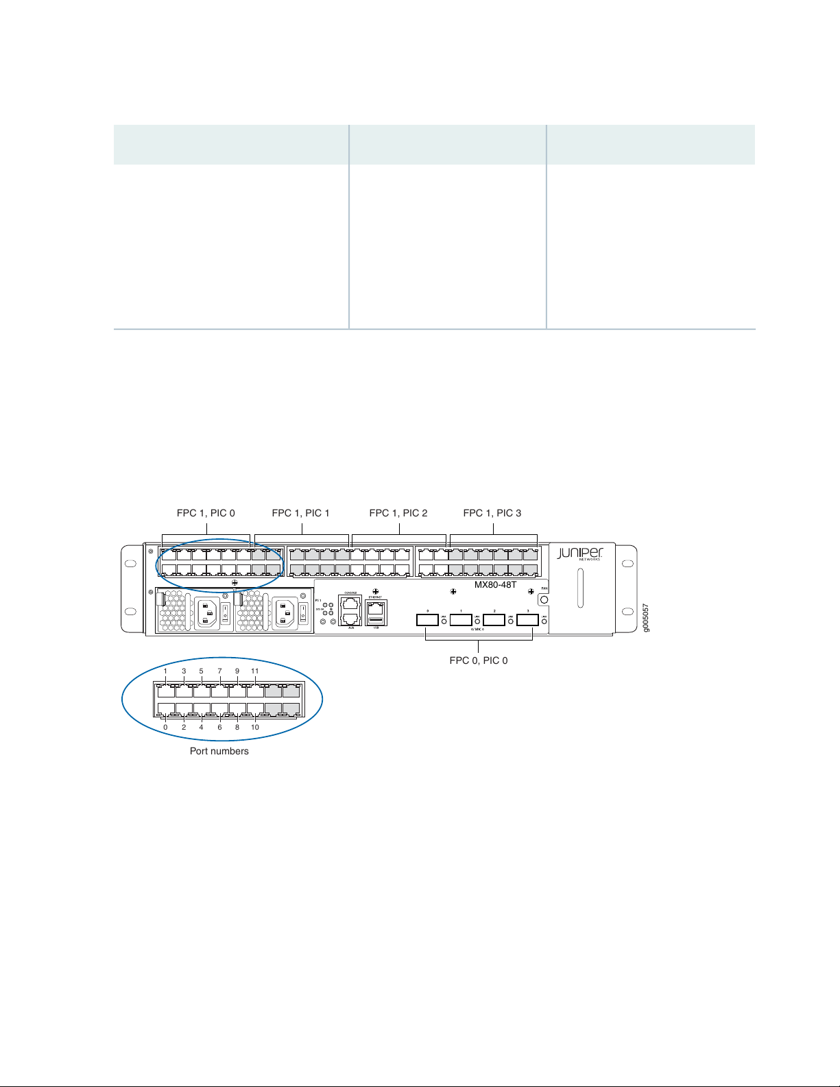
Table 29: MX5, MX10, MX40, and MX80 Components and Their Interface Names (continued)
g005057
MX80-48T
1 3 5 7 9 11
0 2 4 6 8 10
FPC 0, PIC 0
Port numbers
FPC 1, PIC 0 FPC 1, PIC 1 FPC 1, PIC 2 FPC 1, PIC 3
Interface NamesName in the CLIComponent
66
MS-MIC-16GMultiservices MIC installed in the rear of
ge/0/2/0
the chassis (no external ports)
Type = ms
fpc = 0
pic = 2
port = 0
Port and Interface Numbering on MX80-48T Routers
Each MX80-48T router contains two built-in MPCs, which are represented in the CLI as FPC 0 and FPC
1 (see Figure 22 on page 66).
Figure 22: MX80-48T Interface Port Mapping
MPC 0 (FPC 0) contains a 4-port 10-Gigabit Ethernet MIC and is built into the front of the chassis. The
MIC is represented as MIC 0 in the CLI and is logically divided into a single PIC, which is represented as
PIC 0.
MPC 1 (FPC 1) contains a 48-port Tri-Rate MIC and is built into the front of the chassis. The MIC is
represented as MIC 0 in the CLI and is logically divided into four PICs, which are numbered 0 through 3.
Each logical PIC on the built-in Tri-Rate MIC contains twelve ports, which are numbered 0 through 11 (see
Figure 22 on page 66).
Table 30 on page 67 summarizes the relationship between the components and the interface names.
Page 67

Table 30: MX80-48T Components and Interface Names
MIC
67
Interface NamesName in the CLIComponent
xe-0/0/0 through xe-0/0/34x 10GE XFPBuilt-in 4-port 10-Gigabit Ethernet
Built-in 48-port Tri-Rate MIC
48x1 RJ45
Each PIC is shown as 12x 1GE(LAN)
RJ45
ge-1/0/port
ge-1/1/port
ge-1/2/port
ge-1/3/port
SEE ALSO
MX5, MX10, MX40, and MX80 Hardware Components and CLI Terminology | 25
MX5, MX10, MX40, and MX80 Modular Interface Card LEDs
The fixed 10-Gigabit Ethernet Modular Interface Card (MIC) has link LEDs located on the front panel. For
more information about the link LEDs for the 10-Gigabit Ethernet MIC, see “Component LEDs on the
MX5, MX10, MX40, and MX80 Front Panel” on page 34.
Each hot-removable and hot-insertable MIC has LEDs located on the faceplate. For more information
about LEDs on the MIC faceplate, see the “LEDs” section for each MIC in the MX Series Interface Module
Reference.
On the fixed MX80 chassis, each of the 48 ports on the fixed Tri-Rate MIC has a link LED.
Table 31 on page 67 describes the link LEDs in more detail.
Table 31: Tri-Rate MIC LEDs
DescriptionStateColor
Green
steadily
Link is up.On
No link.Off
Page 68

2
CHAPTER
Site Planning, Preparation, and
Specifications
MX5, MX10, MX40, and MX80 Site Preparation Checklist | 69
MX5, MX10, MX40, and MX80 Site Guidelines and Requirements | 71
MX5, MX10, MX40, and MX80 Network Cable and Transceiver Planning | 80
MX5, MX10, MX40, and MX80 Management, and Console Port Specifications and
Pinouts | 85
Page 69

MX5, MX10, MX40, and MX80 Site Preparation Checklist
The checklist in Table 32 on page 69 summarizes the tasks you must perform when preparing a site for
router installation.
Table 32: MX80 Site Preparation Checklist
DatePerformed ByFor More InformationItem or Task
Environment
69
Verify that environmental factors such as
temperature and humidity do not exceed
router tolerances.
Power
Locate sites for connection of system
grounding.
Measure distance between external power
sources and router installation site.
Calculate the power consumption and
requirements.
“MX5, MX10, MX40, and MX80
Router Environmental
Specifications” on page 72
“MX5, MX10, MX40, and MX80
Router Grounding Specifications”
on page 73
“MX5, MX10, MX40, and MX80
Routers AC Power Specifications”
on page 39
“MX5, MX10, MX40, and MX80
Routers DC Power Specifications”
on page 44
“Power Consumption for an
AC-Powered MX5, MX10, MX40,
and MX80 Router” on page 40
Rack
“Power Consumption for a
DC-Powered MX5, MX10, MX40,
and MX80 Router” on page 44
Page 70

Table 32: MX80 Site Preparation Checklist (continued)
70
DatePerformed ByFor More InformationItem or Task
Select the type of rack or cabinet.
Plan rack or cabinet location, including
required space clearances.
If a rack is used, secure rack to floor and
building structure.
“MX5, MX10, MX40, and MX80
Rack Requirements” on page 75
“MX5, MX10, MX40, and MX80
Routers Cabinet Requirements and
Specifications” on page 78
“MX5, MX10, MX40, and MX80
Rack Requirements” on page 75
“MX5, MX10, MX40, and MX80
Routers Clearance Requirements
for Airflow and Hardware
Maintenance” on page 77
“MX5, MX10, MX40, and MX80
Routers Cabinet Requirements and
Specifications” on page 78
“MX5, MX10, MX40, and MX80
Rack Requirements” on page 75
Cables
Acquire cables and connectors:
Determine the number of cables needed
•
based on your planned configuration.
Review the maximum distance allowed
•
for each cable. Choose the length of cable
based on the distance between the
hardware components being connected.
“Calculating Power Budget and
Power Margin for Fiber-Optic
Cables” on page 82
RELATED DOCUMENTATION
MX5, MX10, MX40, and MX80 Installation Summary | 89
Tools Required to Install MX5, MX10, MX40, and MX80 Chassis in the Rack | 95
Page 71

MX5, MX10, MX40, and MX80 Site Guidelines and Requirements
IN THIS SECTION
MX5, MX10, MX40, and MX80 Routers Physical Specifications | 71
MX5, MX10, MX40, and MX80 Router Environmental Specifications | 72
MX5, MX10, MX40, and MX80 Router Grounding Specifications | 73
MX5, MX10, MX40, and MX80 Rack Requirements | 75
MX5, MX10, MX40, and MX80 Routers Clearance Requirements for Airflow and Hardware Maintenance | 77
MX5, MX10, MX40, and MX80 Routers Cabinet Requirements and Specifications | 78
71
MX5, MX10, MX40, and MX80 Routers Physical Specifications
Table 33 on page 71 summarizes the physical specifications for the router.
Table 33: MX5, MX10, MX40, and MX80 Physical Specifications
Fixed chassis
and power supplies:
28 lb (12.7 kg)
Modular chassis
tray, power supplies,
and MICs: 30 lb
(13.6 kg)
17.5 in. (44.5 cm)Chassis with fan tray
(including cable
management
bracket and MIC
release lever)
17.5 in. (44.5 cm)Chassis with fan
(including cable
management
bracket and MIC
release lever)
HeightDepthWidthWeightDescription
3.5 in. (8.9 cm)23.46 in. (59.6 cm)
3.5 in. (8.9 cm)23.46 in. (59.6 cm)
3.35 in. (8.5 cm)18.43 in. 46.81 cm)0.25 in. (0.64 cm)0.1 lb (0.05 kg)Air filter
MIC
1.2 in. (3.05 cm)6.8 in (17.3 cm)6.25 in. (15.9 cm)Maximum up to
1.2 lb (0.54 kg)
Page 72

Table 33: MX5, MX10, MX40, and MX80 Physical Specifications (continued)
72
HeightDepthWidthWeightDescription
1.2 in. (3.05 cm)6.8 in (17.3 cm)12.5 in. (31.75 cm)1.9 lb (0.9 kg)Dual-wide MIC
3.35 in. (8.5 cm)20.5 in. 52.07 cm)2.75 in. (6.96 cm)2.3 lb (1.04 kg)Fan tray
1.6 in. (4.1 cm)13.2 in. (33.5 cm)2.8 in. (7.1 cm)2.6 lb (1.18 kg)DC power supply
13.2 in. (33.5 cm)2.8 in. (7.1 cm)2.6 lb (1.18 kg)AC power supply
1.6 in. (4.1 cm)MX5,
MX10, MX40, and
MX80 Chassis
SEE ALSO
MX5, MX10, MX40, and MX80 Router Overview | 20
MX5, MX10, MX40 and MX80 Chassis Lifting Guidelines | 184
MX5, MX10, MX40, and MX80 Router Environmental Specifications
Table 34 on page 72 specifies the environmental specifications required for normal router operation. In
addition, the site should be as dust-free as possible.
Table 34: Router Environmental Specifications
ValueDescription
Relative humidity
Temperature
Seismic
No performance degradation to 10,000 ft (3048 m)Altitude
Normal operation ensured in relative humidity range of 5% to
90%, noncondensing
Normal operation ensured in temperature range of 32°F (0°C)
to 104°F (40°C)
Nonoperating storage temperature in shipping container:
–40°F (–40°C) to 158°F (70°C)
Designed to meet Telcordia Technologies Zone 4 earthquake
requirements
Page 73

Table 34: Router Environmental Specifications (continued)
ValueDescription
1705 BTU/hour (500 W)Maximum thermal output
NOTE: Install the router only in restricted areas, such as dedicated equipment rooms and
equipment closets, in accordance with Articles 110-16, 110-17, and 110-18 of the National
Electrical Code, ANSI/NFPA 70.
SEE ALSO
Routine Maintenance Procedures for MX5, MX10, MX40, and MX80 Routers | 116
73
General Safety Guidelines for Juniper Networks Devices | 176
General Safety Warnings for Juniper Networks Devices | 177
MX5, MX10, MX40, and MX80 Router Grounding Specifications
IN THIS SECTION
Grounding Points Specifications | 73
Grounding Cable Lug Specifications | 74
Grounding Cable Specifications | 75
Grounding Points Specifications
To meet safety and electromagnetic interference (EMI) requirements and to ensure proper operation, the
router must be adequately grounded before power is connected. To ground AC-powered and DC-powered
routers, you must connect a grounding cable to earth ground and then attach it to the chassis grounding
points using the two screws provided (see Figure 23 on page 74).
Page 74

Two threaded holes are provided on the upper rear of the chassis for connecting the router to earth ground.
g005009
CLOCK
SYNC
Protective
earthing terminal
(grounding points)
All measurements in inches
0.2
dia.
6 AWG conductor
1.69
0.625
g005042
0.38
End view
0.06
The grounding points fit SAE 10-32 screws (American). The grounding points are spaced at 0.625-in.
(15.86-mm) centers.
NOTE: Additional grounding is provided to an AC-powered router when you plug its power
supplies into grounded AC power receptacles.
Figure 23: Grounding Points on MX5, MX10, MX40, and MX80 Routers
74
Grounding Cable Lug Specifications
The accessory box shipped with the router includes one cable lug that attaches to the grounding cable
(see Figure 24 on page 74) and two SAE 10–32 screws used to secure the grounding cable to the grounding
points.
Figure 24: Grounding Cable Lug
CAUTION: Before router installation begins, a licensed electrician must attach a cable
lug to the grounding and power cables that you supply. A cable with an incorrectly
attached lug can damage the router.
Page 75

Grounding Cable Specifications
You must provide one grounding cable that meets the following specifications: 6-AWG (13.3 mm2), minimum
60° C wire, or as required by the local code.
SEE ALSO
Tools and Parts Required for MX5, MX10, MX40, and MX80 Router Grounding and Power
Connections | 98
Preventing Electrostatic Discharge Damage to an MX5, MX10, MX40, and MX80 Router | 181
MX5, MX10, MX40, and MX80 Routers AC Power Specifications | 39
MX5, MX10, MX40, and MX80 Routers DC Power Specifications | 44
75
MX5, MX10, MX40, and MX80 Rack Requirements
The router can be installed in a rack. Many types of racks are acceptable, including four-post (telco) racks
and open-frame racks. An example of an open-frame rack appears in Figure 25 on page 77.
Table 35 on page 75 summarizes rack requirements and specifications for the MX5, MX10, MX40, and
MX80 router.
Table 35: MX5, MX10, MX40, and MX80 Rack Requirements and Specifications
GuidelinesRack Requirement
Rack type and mounting bracket
hole spacing
Use a four-post rack or a two-post rack. You can mount the router on any
four-post or two-post rack that provides bracket holes or hole patterns spaced
at 1 U (1.75-in./4.44-cm) increments and that meets the size and strength
requirements specified in this table.
A U is the standard rack unit defined in Cabinets, Racks, Panels, and Associated
Equipment (document number EIA-310–D) published by the Electronics
Components Industry Association (http://www.ecianow.org/).
Page 76

Table 35: MX5, MX10, MX40, and MX80 Rack Requirements and Specifications (continued)
GuidelinesRack Requirement
76
Rack size and strength
Ensure that the rack is a 19-in. rack as defined in Cabinets, Racks, Panels, and
•
Associated Equipment (document number EIA-310–D) published by the
Electronics Components Industry Association (http://www.ecianow.org/).
Ensure that the rack is one of the following standard lengths:
•
23.62 in. (600 mm)
•
30.0 in. (762 mm)
•
31.5 in. (800 mm)
•
The rack rails must be spaced widely enough to accommodate the router
•
chassis's external dimensions: 3.5 in. (8.9 cm) high, 23.46 in. (59.6 cm) deep,
and 17.5 in. (44.5 cm) wide. The outer edges of the mounting brackets extend
the width to 19.2 in. (48.7 cm). The spacing of rails and adjacent racks must
also allow for the clearances around the router and rack that are specified in
“MX5, MX10, MX40, and MX80 Routers Clearance Requirements for Airflow
and Hardware Maintenance” on page 77.
The router ships with the mounting brackets installed in the front-mount
•
position. You can also move the brackets to the center-mount position. For
instructions about moving the mounting hardware, see “Moving the Mounting
Brackets for Center-Mounting MX5, MX10, MX40, and MX80 Routers” on
page 94.
The chassis height of 3.5 in. (8.9 cm) is approximately 2 U.
•
The rack must be strong enough to support the weight of the fully configured
•
router, up to 30 lb (13.6 kg).
Ensure that the spacing of rails and adjacent racks allows for the proper
•
clearance around the router and rack as specified in “MX5, MX10, MX40, and
MX80 Routers Clearance Requirements for Airflow and Hardware
Maintenance” on page 77.
Rack connection to the building
structure
Secure the rack to the building structure.
•
If earthquakes are a possibility in your geographic area, secure the rack to
•
the floor.
Secure the rack to the ceiling brackets as well as wall or floor brackets for
•
maximum stability.
Page 77

Figure 25: Typical Open-Frame Rack
77
MX5, MX10, MX40, and MX80 Routers Clearance Requirements for Airflow and Hardware Maintenance
When planning the installation site, allow sufficient clearance around the rack (see Figure 26 on page 78):
For the cooling system to function properly, the airflow around the chassis must be unrestricted. Allow
•
at least 6 in. (15.2 cm) of clearance between side-cooled routers. Allow 2.8 in. (7 cm) between the side
of the chassis and any non-heat-producing surface such as a wall.
For service personnel to remove and install hardware components, there must be adequate space at the
•
front and back of the router. At least 24 in. (61 cm) are required both in front of and behind the router.
NEBS GR-63 recommends that you allow at least 30 in. (76.2 cm) in front of the rack and 24 in. (61 cm)
behind the router.
Page 78

Figure 26: MX5, MX10, MX40, and MX80 Chassis Dimensions and Clearance Requirements
Rear of chassis
Front of chassis
17.5"
(44.5 cm)
20.2"
(51.3 cm)
g005017
Front-mounting flange
19.2"
(48.7 cm)
24" (61 cm)
clearance required
30" (76.2 cm)
clearance recommended for
maintenance
Cable
management
bracket
23.46"
(59.6cm)
78
MX5, MX10, MX40, and MX80 Routers Cabinet Requirements and Specifications
Table 36 on page 78 summarizes cabinet requirements and specifications for MX5, MX10, MX40, and
MX80 routers.
Table 36: Cabinet Requirements and Specifications for an MX5, MX10, MX40, and MX80 Router
Guidelines for the MX80 RouterCabinet Requirement
Cabinet size and clearance
The minimum-sized cabinet that can accommodate the router is 19-in. (482-mm)
•
wide and 23.62-in. (600-mm) deep. A cabinet larger than the minimum
requirement provides better airflow and reduces the chance of overheating. If
you provide adequate cooling air and airflow clearance, you can stack several
routers in a cabinet that has sufficient usable vertical space. Each router requires
2 U.
A U is the standard rack unit defined in Cabinets, Racks, Panels, and Associated
Equipment (document number EIA-310-D) published by the Electronic
Components Industry Association (ECIA) (http://www.ecianow.org).
With adequate cooling air and airflow clearance, you can stack multiple MX5,
•
MX10, MX40, and MX80 routers in a cabinet with a four-post rack. In all cases,
the rack must meet the strength requirements to support the weight.
The minimum total clearance inside the cabinet is 30.7 in. (780 mm) between
•
the inside of the front door and the inside of the rear door.
Page 79

Table 36: Cabinet Requirements and Specifications for an MX5, MX10, MX40, and MX80 Router (continued)
g005016
Front view
airflow
Fan tray/
air filter
Power supply exhaust
Guidelines for the MX80 RouterCabinet Requirement
79
Cabinet airflow requirements
When you install the router in a cabinet, you must ensure that ventilation through
the cabinet is sufficient to prevent overheating. Consider the following
requirements to when planning for chassis cooling:
Airflow must always be from front to back with respect to the rack. If the device
•
has side to rear airflow, then provisions must be made to ensure that fresh air
from the front of the rack is supplied to the inlets, and exhaust exits the rear
of the rack. The device must not interfere with the cooling of other systems
in the rack. Fillers must be used as appropriate in the rack to ensure there is
no recirculation of heated exhaust air back to the front of the rack. Care must
also be taken around cables to ensure no leakage of air in situations where
recirculation may result.
Ensure that the cabinet allows the chassis hot exhaust air to exit from the
•
cabinet without recirculating into the router. An open cabinet (without a top
or doors) that employs hot air exhaust extraction from the top allows the best
airflow through the chassis. If the cabinet contains a top or doors, perforations
in these elements assist with removing the hot air exhaust. For an illustration
of chassis airflow, see Figure 27 on page 79.
Ensure that the cool air supply you provide through the cabinet can adequately
•
dissipate the thermal output of the router.
Route and dress all cables to minimize the blockage of airflow to and from the
•
chassis.
Ensure that the spacing of rails and adjacent racks allows for the proper
•
clearance around the router and rack as specified in “MX5, MX10, MX40, and
MX80 Routers Clearance Requirements for Airflow and Hardware Maintenance”
on page 77.
Install the router as close as possible to the front of the cabinet so that the
•
chassis just clears the inside of the front door. This maximizes the clearance in
the rear of the cabinet for critical airflow.
Figure 27: Airflow Through Chassis
Page 80

SEE ALSO
MX5, MX10, MX40, and MX80 Cooling System Description
Installing MX5, MX10, MX40, and MX80 Chassis in the Rack | 96
MX5, MX10, MX40, and MX80 Network Cable and Transceiver Planning
IN THIS SECTION
Determining Transceiver Support and Specifications for M Series and T Series Routers | 80
Fiber-Optic Cable Signal Loss, Attenuation, and Dispersion | 81
80
Calculating Power Budget and Power Margin for Fiber-Optic Cables | 82
Routing Engine Interface Cable Specifications for MX5, MX10, MX40, and MX80 Routers | 85
Determining Transceiver Support and Specifications for M Series and T Series Routers
You can find information about the pluggable transceivers supported on your Juniper Networks device
by using the Hardware Compatibility Tool. In addition to transceiver and connector type, the optical and
cable characteristics—where applicable—are documented for each transceiver. The Hardware Compatibility
Tool allows you to search by product, displaying all the transceivers supported on that device, or category,
displaying all the transceivers by interface speed or type. The Hardware Compatibility Tool is located at
https://apps.juniper.net/hct/.
Some transceivers support additional monitoring using the operational mode CLI command show interfaces
diagnostics optics. Use the Hardware Compatibility Tool to determine if your transceiver supports
monitoring. See the Junos OS documentation for your device for a description of the monitoring fields.
Page 81

CAUTION: If you face a problem running a Juniper Networks device that uses a
third-party optic or cable, the Juniper Networks Technical Assistance Center (JTAC)
can help you diagnose the source of the problem. Your JTAC engineer might recommend
that you check the third-party optic or cable and potentially replace it with an equivalent
Juniper Networks optic or cable that is qualified for the device.
Fiber-Optic Cable Signal Loss, Attenuation, and Dispersion
IN THIS SECTION
Signal Loss in Multimode and Single-Mode Fiber-Optic Cable | 81
81
Attenuation and Dispersion in Fiber-Optic Cable | 81
Signal Loss in Multimode and Single-Mode Fiber-Optic Cable
Multimode fiber is large enough in diameter to allow rays of light to reflect internally (bounce off the walls
of the fiber). Interfaces with multimode optics typically use LEDs as light sources. However, LEDs are not
coherent sources. They spray varying wavelengths of light into the multimode fiber, which reflects the
light at different angles. Light rays travel in jagged lines through a multimode fiber, causing signal dispersion.
When light traveling in the fiber core radiates into the fiber cladding, higher-order mode loss results.
Together these factors limit the transmission distance of multimode fiber compared with single-mode
fiber.
Single-mode fiber is so small in diameter that rays of light can reflect internally through one layer only.
Interfaces with single-mode optics use lasers as light sources. Lasers generate a single wavelength of light,
which travels in a straight line through the single-mode fiber. Compared with multimode fiber, single-mode
fiber has higher bandwidth and can carry signals for longer distances.
Exceeding the maximum transmission distances can result in significant signal loss, which causes unreliable
transmission.
Attenuation and Dispersion in Fiber-Optic Cable
Correct functioning of an optical data link depends on modulated light reaching the receiver with enough
power to be demodulated correctly. Attenuation is the reduction in power of the light signal as it is
Page 82

transmitted. Attenuation is caused by passive media components, such as cables, cable splices, and
connectors. Although attenuation is significantly lower for optical fiber than for other media, it still occurs
in both multimode and single-mode transmission. An efficient optical data link must have enough light
available to overcome attenuation.
Dispersion is the spreading of the signal over time. The following two types of dispersion can affect an
optical data link:
Chromatic dispersion—Spreading of the signal over time resulting from the different speeds of light rays.
•
Modal dispersion—Spreading of the signal over time resulting from the different propagation modes in
•
the fiber.
For multimode transmission, modal dispersion, rather than chromatic dispersion or attenuation, usually
limits the maximum bit rate and link length. For single-mode transmission, modal dispersion is not a factor.
However, at higher bit rates and over longer distances, chromatic dispersion rather than modal dispersion
limits maximum link length.
An efficient optical data link must have enough light to exceed the minimum power that the receiver
requires to operate within its specifications. In addition, the total dispersion must be less than the limits
specified for the type of link in Telcordia Technologies document GR-253-CORE (Section 4.3) and
International Telecommunications Union (ITU) document G.957.
82
When chromatic dispersion is at the maximum allowed, its effect can be considered as a power penalty in
the power budget. The optical power budget must allow for the sum of component attenuation, power
penalties (including those from dispersion), and a safety margin for unexpected losses.
Calculating Power Budget and Power Margin for Fiber-Optic Cables
Use the information in this topic and the specifications for your optical interface to calculate the power
budget and power margin for fiber-optic cables.
TIP: You can use the Hardware Compatibility Tool to find information about the pluggable
transceivers supported on your Juniper Networks device.
To calculate the power budget and power margin, perform the following tasks:
1.
How to Calculate Power Budget for Fiber-Optic Cable | 83
2.
How to Calculate Power Margin for Fiber-Optic Cable | 83
Page 83

How to Calculate Power Budget for Fiber-Optic Cable
To ensure that fiber-optic connections have sufficient power for correct operation, you need to calculate
the link's power budget, which is the maximum amount of power it can transmit. When you calculate the
power budget, you use a worst-case analysis to provide a margin of error, even though all the parts of an
actual system do not operate at the worst-case levels. To calculate the worst-case estimate of power
budget (PB), you assume minimum transmitter power (PT) and minimum receiver sensitivity (PR):
83
PB= PT– P
R
The following hypothetical power budget equation uses values measured in decibels (dB) and decibels
referred to one milliwatt (dBm):
PB= PT– P
R
PB= –15 dBm – (–28 dBm)
PB= 13 dB
How to Calculate Power Margin for Fiber-Optic Cable
After calculating a link's power budget, you can calculate the power margin (PM), which represents the
amount of power available after subtracting attenuation or link loss (LL) from the power budget (PB). A
worst-case estimate of PMassumes maximum LL:
PM= PB– LL
PMgreater than zero indicates that the power budget is sufficient to operate the receiver.
Factors that can cause link loss include higher-order mode losses, modal and chromatic dispersion,
connectors, splices, and fiber attenuation. Table 37 on page 83 lists an estimated amount of loss for the
factors used in the following sample calculations. For information about the actual amount of signal loss
caused by equipment and other factors, refer to vendor documentation.
Table 37: Estimated Values for Factors Causing Link Loss
Estimated Link-Loss ValueLink-Loss Factor
Higher-order mode losses
Modal and chromatic dispersion
Single mode—None
Multimode—0.5 dB
Single mode—None
Multimode—None, if product of bandwidth and distance is less than
500 MHz-km
Page 84

Table 37: Estimated Values for Factors Causing Link Loss (continued)
Estimated Link-Loss ValueLink-Loss Factor
0.5 dBConnector
0.5 dBSplice
84
Fiber attenuation
Single mode—0.5 dB/km
Multimode—1 dB/km
The following sample calculation for a 2-km-long multimode link with a power budget (PB) of 13 dB uses
the estimated values from Table 37 on page 83 to calculate link loss (LL) as the sum of fiber attenuation
(2 km @ 1 dB/km, or 2 dB) and loss for five connectors (0.5 dB per connector, or 2.5 dB) and two splices
(0.5 dB per splice, or 1 dB) as well as higher-order mode losses (0.5 dB). The power margin (PM) is calculated
as follows:
PM= PB– LL
PM= 13 dB – 2 km (1 dB/km) – 5 (0.5 dB) – 2 (0.5 dB) – 0.5 dB
PM= 13 dB – 2 dB – 2.5 dB – 1 dB – 0.5 dB
PM= 7 dB
The following sample calculation for an 8-km-long single-mode link with a power budget (PB) of 13 dB
uses the estimated values from Table 37 on page 83 to calculate link loss (LL) as the sum of fiber attenuation
(8 km @ 0.5 dB/km, or 4 dB) and loss for seven connectors (0.5 dB per connector, or 3.5 dB). The power
margin (PM) is calculated as follows:
PM= PB– LL
PM= 13 dB – 8 km (0.5 dB/km) – 7(0.5 dB)
PM= 13 dB – 4 dB – 3.5 dB
PM= 5.5 dB
In both examples, the calculated power margin is greater than zero, indicating that the link has sufficient
power for transmission and does not exceed the maximum receiver input power.
Page 85

Routing Engine Interface Cable Specifications for MX5, MX10, MX40, and MX80 Routers
Table 38 on page 85 lists the specifications for the cables that connect to management ports.
Table 38: Cable Specifications for Routing Engine Management
85
Maximum
Length
328 ft (100 m)One 15-ft
Routing Engine
console or
auxiliary
interface
Routing Engine
Ethernet
interface
Cable
SpecificationPort
RS-232
(EIA-232) serial
cable
Category 5
cable or
equivalent
suitable for
100Base-T
operation
Cable/Wire
Supplied
(1.83-m) length
with
RJ-45/DB-9
connectors
(4.57-m) length
with
RJ-45/RJ-45
connectors
SEE ALSO
MX5, MX10, MX40, and MX80 Routing Engine Description | 49
Router
Receptacle
RJ-45 socket6 ft (1.83 m)One 6-ft
RJ-45
autosensing
Maintaining the MX5, MX10, MX40, and MX80 Routing Engine | 116
MX5, MX10, MX40, and MX80 Management, and Console Port Specifications and Pinouts
IN THIS SECTION
RJ-45 Connector Pinouts for the AUX and CONSOLE Ports on MX5, MX10, MX40, and MX80 Routers | 86
RJ-45 Connector Pinouts for the ETHERNET Port on MX5, MX10, MX40, and MX80 Routers | 86
Page 86

RJ-45 Connector Pinouts for the AUX and CONSOLE Ports on MX5, MX10, MX40, and MX80 Routers
The ports on the front panel labeled AUX and CONSOLE are asynchronous serial interfaces that accept
an RJ-45 connector. The ports connect the Routing Engine to an auxiliary or console management device.
Table 39 on page 86 describes the RJ-45 connector pinout.
Table 39: RJ-45 Connector Pinout for the AUX and CONSOLE Ports
DescriptionSignalPin
Request to SendRTS1
Data Terminal ReadyDTR2
Transmit DataTXD3
86
Signal GroundGround4
Signal GroundGround5
Receive DataRXD6
Data Set ReadyDSR/DCD7
Clear to SendCTS8
SEE ALSO
MX5, MX10, MX40, and MX80 Routing Engine Description | 49
Maintaining the MX5, MX10, MX40, and MX80 Routing Engine | 116
RJ-45 Connector Pinouts for the ETHERNET Port on MX5, MX10, MX40, and MX80 Routers
The port on the front panel labeled ETHERNET is an autosensing 10/100-Mbps Ethernet RJ-45 receptacle
that accepts an Ethernet cable for connecting the Routing Engine to a management LAN (or other device
that supports out-of-band management). Table 40 on page 87 describes the RJ-45 connector pinout.
Page 87

Table 40: RJ-45 Connector Pinout for the Routing Engine ETHERNET Port
SignalPin
TX+1
TX–2
RX+3
Termination network4
Termination network5
RX–6
Termination network7
87
Termination network8
Page 88

3
CHAPTER
Initial Installation and Configuration
MX5, MX10, MX40, and MX80 Installation Summary | 89
Unpacking and Mounting the MX5, MX10, MX40, and MX80 | 90
Connecting the MX5, MX10, MX40, and MX80 Routers to Power | 98
Connecting MX5, MX10, MX40, and MX80 Routers to Management Devices | 108
Initially Configuring MX5, MX10, MX40, and MX80 Routers | 110
Page 89

MX5, MX10, MX40, and MX80 Installation Summary
To install the router:
1. Prepare your installation site.
See “MX5, MX10, MX40, and MX80 Site Preparation Checklist” on page 69.
2. Review the safety guidelines and warnings:
See “General Safety Guidelines for Juniper Networks Devices” on page 176.
•
See “General Safety Warnings for Juniper Networks Devices” on page 177.
•
3. Unpack the router and verify the parts:
a. See “Unpacking MX5, MX10, MX40, and MX80 Routers” on page 90.
b. See “Verifying the MX5, MX10, MX40, and MX80 Routers Parts Received” on page 91.
89
4. Install the mounting hardware.
See “Moving the Mounting Brackets for Center-Mounting MX5, MX10, MX40, and MX80 Routers” on
page 94.
5. Lift the router onto the rack.
See “Installing MX5, MX10, MX40, and MX80 Chassis in the Rack” on page 96.
6. Connect cables to the network and external devices:
See “Connecting MX5, MX10, MX40, and MX80 Routers to Management Devices” on page 108.
•
See Connecting Interface Cables to MX5, MX10, MX40, and MX80 Routers.
•
7. Connect the grounding cable.
See “Grounding MX5, MX10, MX40, and MX80 Routers” on page 99.
8. Connect the AC power cord or DC power cables:
See “Connecting Power to an AC-Powered MX5, MX10, MX40, and MX80 Router” on page 100.
•
•
See “Connecting Power to a DC-Powered MX5, MX10, MX40, and MX80 Router” on page 102.
•
Powering On a DC-Powered MX5, MX10, MX40, and MX80 Router on page 105
•
9. Power on the router:
Page 90

Powering On an AC-Powered MX5, MX10, MX40, and MX80 Router on page 101
•
Powering On a DC-Powered MX5, MX10, MX40, and MX80 Router on page 105
•
10. Perform the initial system configuration.
See “Initially Configuring MX5, MX10, MX40, and MX80 Routers” on page 110.
Unpacking and Mounting the MX5, MX10, MX40, and MX80
IN THIS SECTION
Tools and Parts Required to Unpack MX5, MX10, MX40, and MX80 Routers | 90
90
Unpacking MX5, MX10, MX40, and MX80 Routers | 90
Verifying the MX5, MX10, MX40, and MX80 Routers Parts Received | 91
Installing the MX5, MX10, MX40, and MX80 Cable Management Bracket | 93
Moving the Mounting Brackets for Center-Mounting MX5, MX10, MX40, and MX80 Routers | 94
Tools Required to Install MX5, MX10, MX40, and MX80 Chassis in the Rack | 95
Installing MX5, MX10, MX40, and MX80 Chassis in the Rack | 96
Tools and Parts Required to Unpack MX5, MX10, MX40, and MX80 Routers
To unpack the router and prepare for installation, you need the following tools:
Blank panels to cover any slots not occupied by a component
•
Unpacking MX5, MX10, MX40, and MX80 Routers
The router is shipped in a cardboard carton and secured with foam packing material. The carton also
contains an accessory box and quick start instructions.
Page 91

NOTE: The router is maximally protected inside the shipping carton. Do not unpack it until you
are ready to begin installation.
To unpack the router:
1. Move the shipping carton to a staging area as close to the installation site as possible, but where you
have enough room to remove the router.
2. Position the carton so that the arrows are pointing up.
3. Open the top flaps on the shipping carton.
4. Remove the accessory box, and verify the contents against the parts inventory on the label attached
to the carton.
91
5. Pull out the packing material holding the router in place.
6. Verify the contents of the carton against the packing list included with the router.
7. Save the shipping carton and packing materials in case you later need to move or ship the router.
Verifying the MX5, MX10, MX40, and MX80 Routers Parts Received
A packing list is included in each shipment. Check the parts in the shipment against the items on the packing
list. The packing list specifies the part numbers and descriptions of each part in your order.
If any part is missing, contact a customer service representative.
A fully configured router contains the router chassis with installed components, listed in Table 41 on page 91,
and an accessory box, which contains the parts listed in Table 42 on page 92. The parts shipped with your
router can vary depending on the configuration you ordered.
Table 41: Parts List for a Fully Configured Router
QuantityComponent
1Chassis
1Air filter
Page 92

Table 41: Parts List for a Fully Configured Router (continued)
QuantityComponent
Up to 2MICs (modular chassis only)
1 or 2DC power supplies
1 or 2AC power supplies
1Fan tray
2Cable management brackets
1Documentation Roadmap
92
Blank panels for slots without components installed
Table 42: Accessory Box Parts List
#6 screw
One blank panel for each slot not
occupied by a component
QuantityPart
4Screws to mount chassis
2Screws to secure the ground cable lug
1Ground terminal lug, 14 AWG, sized for #10 screw
9DC power fork terminal lugs, 16-14 AWG, sized for
1Label, “Small Parts Enclosed”
1Label, “Accessories Contents”
1USB flash drive with Junos OS
1Read me first document
1Affidavit for T1 connection
1Juniper Networks Product Warranty
1End User License Agreement
Page 93

Table 42: Accessory Box Parts List (continued)
93
QuantityPart
1Documentation addendum card, MX80
1Document sleeve
23 in. x 5 in. pink bag
29 in. x 12 in. pink bag, ESD
1Accessory box, 19 in. x 12 in. x 3 in.
1Ethernet cable, RJ-45 to DB-9
1ESD wrist strap with cable
Installing the MX5, MX10, MX40, and MX80 Cable Management Bracket
The cable management bracket attaches to the left side of the router. To install the cable management
bracket (see Figure 28 on page 94):
1. Wrap and fasten one end of the ESD grounding strap around your bare wrist, and connect the other
end of the strap to an ESD point.
2. Position the cable management bracket on the left side of the front of the chassis.
3. Tighten the screws at the bottom and top of the bracket.
Page 94

Figure 28: Installing the Cable Management Bracket
g005036
94
SEE ALSO
MX5, MX10, MX40, and MX80 Site Preparation Checklist | 69
MX5, MX10, MX40, and MX80 Installation Summary | 89
Installing MX5, MX10, MX40, and MX80 Chassis in the Rack | 96
Connecting MX5, MX10, MX40, and MX80 Routers to Management Devices | 108
Connecting Interface Cables to MX5, MX10, MX40, and MX80 Routers
Moving the Mounting Brackets for Center-Mounting MX5, MX10, MX40, and MX80 Routers
Two removable mounting brackets are attached to the mounting holes closest to the front of the chassis
(see Figure 29 on page 95). You can move the pair of brackets to another position on the side of the chassis
for center-mounting the router.
To move the mounting brackets from the front of the chassis toward the center of the chassis (see
Figure 30 on page 95):
1. Remove the four screws at the top and bottom of the bracket.
2. Pull the bracket away from the chassis.
3. Align the bracket with the two sets of mounting holes located toward the center of the chassis.
Page 95

4. Insert the four screws at the top and bottom of the bracket and tighten each partially.
g005018
g005019
5. Tighten the four screws completely.
6. Repeat the procedure for the other bracket.
Figure 29: Front-Mounting the Brackets on MX5, MX10, MX40, and MX80 Routers
95
Figure 30: Center-Mounting the Brackets on MX5, MX10, MX40, and MX80 Routers
Tools Required to Install MX5, MX10, MX40, and MX80 Chassis in the Rack
To install the router, you need the following tools and parts:
Phillips (+) screwdriver, number 2
•
ESD grounding wrist strap
•
Page 96

SEE ALSO
MX5, MX10, MX40, and MX80 Site Preparation Checklist | 69
MX5, MX10, MX40, and MX80 Installation Summary | 89
Installing MX5, MX10, MX40, and MX80 Chassis in the Rack | 96
Installing MX5, MX10, MX40, and MX80 Chassis in the Rack
To install the router in the rack (see Figure 31 on page 97 and Figure 32 on page 97):
CAUTION: If you are installing more than one router in a rack, install the lowest one
first. Installing a router in an upper position in a rack or cabinet requires a lift.
96
CAUTION: Before front mounting the router in a rack, have a qualified technician
verify that the rack is strong enough to support the router's weight and is adequately
supported at the installation site.
CAUTION: Lifting the chassis and mounting it in a rack requires two people (one person
to hold the router in place and a second person to install the screws). The chassis
weighs approximately 30 lb (13.6 kg).
1. Ensure that the rack is in its permanent location and is secured to the building. Ensure that the installation
site allows adequate clearance for both airflow and maintenance.
2. Position the router in front of the rack or cabinet.
3. Hold onto the bottom of the chassis and carefully lift it so that the mounting brackets contact the rack
rails.
WARNING: To prevent injury, keep your back straight and lift with your legs, not
your back. Avoid twisting your body as you lift. Balance the load evenly and be sure
that your footing is solid.
Page 97

4. Align the mounting brackets with the holes in the rack rails.
Mounting rack
Mounting bracket
g005020
Mounting rack
Mounting bracket
g005044
5. Install a mounting screw into each of the open mounting holes aligned with the rack, starting from the
bottom.
6. Visually inspect the alignment of the router. If the router is installed properly in the rack, all the mounting
screws on one side of the rack should be aligned with the mounting screws on the opposite side, and
the router should be level.
Figure 31: Installing the Front-Mounted Router in the Rack
97
Figure 32: Installing the Center-Mounted Router in the Rack
SEE ALSO
Page 98

MX5, MX10, MX40, and MX80 Site Preparation Checklist | 69
MX5, MX10, MX40, and MX80 Installation Summary | 89
Unpacking MX5, MX10, MX40, and MX80 Routers | 90
Tools Required to Install MX5, MX10, MX40, and MX80 Chassis in the Rack | 95
Connecting the MX5, MX10, MX40, and MX80 Routers to Power
IN THIS SECTION
Tools and Parts Required for MX5, MX10, MX40, and MX80 Router Grounding and Power Connections | 98
Grounding MX5, MX10, MX40, and MX80 Routers | 99
98
Connecting Power to an AC-Powered MX5, MX10, MX40, and MX80 Router | 100
Powering On an AC-Powered MX5, MX10, MX40, and MX80 Router | 101
Connecting Power to a DC-Powered MX5, MX10, MX40, and MX80 Router | 102
Powering On a DC-Powered MX5, MX10, MX40, and MX80 Router | 105
Powering Off MX5, MX10, MX40, and MX80 Routers | 107
Tools and Parts Required for MX5, MX10, MX40, and MX80 Router Grounding and Power Connections
To ground and provide power to the router, you need the following tools and parts:
Phillips (+) screwdrivers, numbers 1 and 2
•
2.5-mm flat-blade (–) screwdriver
•
Torque-controlled driver, with a maximum torque capacity of 6 lb-in., for tightening screws to terminals
•
on each power supply on a DC-powered router
Page 99

CAUTION: The maximum torque rating of the terminal screws on the DC power
supply is 6 lb-in. (0.7 Nm). The terminal screws may be damaged if excessive torque
is applied. Use only a torque-controlled driver to tighten screws on the DC power
supply terminals. Use an appropriately sized driver, with a maximum torque capacity
of 6 lb-in. or less. Ensure that the driver is undamaged and properly calibrated and
that you have been trained in its use. You may wish to use a driver that is designed
to prevent overtorque when the preset torque level is achieved.
Wire cutters
•
Electrostatic discharge (ESD) grounding wrist strap
•
Grounding MX5, MX10, MX40, and MX80 Routers
99
You ground the router by connecting a grounding cable to earth ground and then attaching it to the chassis
grounding points using two SAE 10-32 screws. You must provide the grounding cables (the cable lugs are
supplied with the router). For grounding cable specifications, see “MX5, MX10, MX40, and MX80 Router
Grounding Specifications” on page 73. To ground the router:
1. Verify that a licensed electrician has attached the cable lug provided with the router to the grounding
cable.
2. Attach an electrostatic discharge (ESD) grounding strap to your bare wrist, and connect the strap to
an approved site ESD grounding point. See the instructions for your site.
3. Ensure that all grounding surfaces are clean and brought to a bright finish before grounding connections
are made.
4. Connect the grounding cable to a proper earth ground.
5. Detach the ESD grounding strap from the site ESD grounding point.
6. Wrap and fasten one end of the ESD grounding strap around your bare wrist, and connect the other
end of the strap to an ESD point.
7. Place the grounding cable lug over the grounding points on the upper rear of the chassis (see
Figure 33 on page 100).
Page 100

8. Secure the grounding cable lug with the screws. The holes are sized for SAE 10-32 screws.
g005009
CLOCK
SYNC
Protective
earthing terminal
(grounding points)
9. Dress the grounding cable, and verify that it does not touch or block access to router components, and
that it does not drape where people could trip on it.
Figure 33: Grounding Points on MX5, MX10, MX40, and MX80 Routers
100
Connecting Power to an AC-Powered MX5, MX10, MX40, and MX80 Router
CAUTION: Do not mix AC and DC power supply modules within the same router.
Damage to the router might occur.
You connect AC power to the router by attaching power cords from the AC power sources to the AC
appliance inlets located on the power supplies.
To connect the AC power cords to the router for each power supply:
1. Locate power cords that have a plug appropriate for your geographic location. For more information,
see “Connecting an MX5, MX10, MX40, and MX80 AC Power Supply Cord” on page 143.
2. Wrap and fasten one end of the ESD grounding strap around your bare wrist, and connect the other
end of the strap to an ESD point.
3. Move the AC input switch next to the appliance inlet on the power supply to the off (O) position.
4. Connect the power cord to the power supply.
 Loading...