

Juniper MX240 - UPGRADING, MX960 - UPGRADING, MX480 - UPGRADING, MX240, MX480 User Manual
...Page 1

Upgrading MX240, MX480, and MX960
3D Universal Edge Router Fan Trays and
Power Supplies
December 2010
Part Number: 530-036423
Revision 02
This documentdescribes the necessary stepsto be taken to upgrade any JuniperNetworks
MX Series 3D Universal Edge Routerchassis to higher capacity cooling and higher capacity
power. Step-by-step descriptions are given for replacement of the various parts in the
chassis. All of these upgrades can be performed while the system is operational, but it
is important to follow the complete process through.
NOTE: Combinations of regular-capacityand high-capacity supplies and fan
trays are not supported outside of the upgrade window.
CAUTION: The router cannot be powered from AC and DC power supplies
simultaneously. The first type of power supply detected by the router when
initially powered on determines the type of power supply allowed by the
router. All installed power supplies of the other type are disabled by the router.
If you install a power supply of the other type while the router is operating,
the router disables the power supply and generates an alarm.
NOTE: Before upgrading, the MX Series router must be running Junos OS
Release 10.0 R1 or later to support high-capacity fan trays. Junos OS Release
10.0R2 is required to support the MX240 and MX480 AC and DC high capacity
power supplies, and the MX960 AC high- capacity power supplies. Junos OS
Release 10.2 R1 is required to support the MX960 DC high-capacity power
supplies.
1Copyright © 2010, Juniper Networks, Inc.
Page 2

Upgrading MX240, MX480, and MX960 3D Universal Edge Router Power Supplies and Fan Trays
The rating upgrade is needed to ensure the chassis rating is in line with the optional higher
capacity power supplies that may be installed in your MX Series router. The upgrade kit
contains the following items; they are also available as spares:
•
Up to four power supplies
•
Up to two fan trays
•
Optional one filter tray (MX960)
•
Rating label
In this guide, three areas are addressed, and all three have to be completed before your
MX Series router is fully enabled for higher capacity power and cooling.
•
Cooling
•
Power
•
Rating label change
Higher capacity cooling is required for some types of DPCs or MPCs, and higher capacity
power is required for a higher number of newer MPCs. Note that there are minimum
softwarerevision requirements for the cooling and power modules. Without this minimum
softwarerevision, these new parts are not supported and likelynot detected and managed
properly.
Contents
NOTE: Before upgrading, the MX Series router must be running Junos OS
Release 10.0 R1 or later to support high-capacity fan trays. Junos OS Release
10.0R2 is required to support the MX240 and MX480 AC and DC high capacity
power supplies, and the MX960 AC high- capacity power supplies. Junos OS
Release 10.2 R1 is required to support the MX960 DC high-capacity power
supplies.
Fan Tray Upgrade Overview . . . . . . . . . . . . . . . . . . . . . . . . . . . . . . . . . . . . . . . . . . . . 4
Replacing the MX240 Fan Tray . . . . . . . . . . . . . . . . . . . . . . . . . . . . . . . . . . . . . . . . . 5
Replacing the MX480 Fan Tray . . . . . . . . . . . . . . . . . . . . . . . . . . . . . . . . . . . . . . . . . 7
Replacing the MX960 Fan Trays . . . . . . . . . . . . . . . . . . . . . . . . . . . . . . . . . . . . . . . . 8
Upgrading the MX960 Air Filter Tray . . . . . . . . . . . . . . . . . . . . . . . . . . . . . . . . . . . . . 11
Removing the MX960 Air Filter . . . . . . . . . . . . . . . . . . . . . . . . . . . . . . . . . . . . . . . . . 11
Installing the MX960 High-Capacity Tray and Filter . . . . . . . . . . . . . . . . . . . . . . . . 12
Fan Tray Power Requirements . . . . . . . . . . . . . . . . . . . . . . . . . . . . . . . . . . . . . . . . . 13
Power Supply Zone Overview . . . . . . . . . . . . . . . . . . . . . . . . . . . . . . . . . . . . . . . . . . 13
Upgrading the MX240 and MX480 AC Power Supplies . . . . . . . . . . . . . . . . . . . . . 14
Removing the MX240 and MX480 AC Power Supplies . . . . . . . . . . . . . . . . . . . . . 14
Installing the MX240 and MX480 AC High-Capacity Power Supplies . . . . . . . . . . 15
Upgrading the MX240 and MX480 DC Power Supplies . . . . . . . . . . . . . . . . . . . . . 16
Removing the MX240 and MX480 DC Power Supplies . . . . . . . . . . . . . . . . . . . . . 16
Setting the MX240 and MX480 DC High-Capacity Power Supply Input Mode
Switch . . . . . . . . . . . . . . . . . . . . . . . . . . . . . . . . . . . . . . . . . . . . . . . . . . . . . . . . . 17
Copyright © 2010, Juniper Networks, Inc.2
Page 3

Installing the MX240 and MX480 DC High-Capacity Power Supplies . . . . . . . . . . 19
Upgrading the MX960 AC Power Supplies Overview . . . . . . . . . . . . . . . . . . . . . . . 22
Removing the MX960 AC Power Supplies . . . . . . . . . . . . . . . . . . . . . . . . . . . . . . . 23
Installing the MX960 AC High-Capacity Power Supplies . . . . . . . . . . . . . . . . . . . . 25
Upgrading the MX960 DC Power Supplies Overview . . . . . . . . . . . . . . . . . . . . . . . 27
Removing an MX960 DC Power Supply . . . . . . . . . . . . . . . . . . . . . . . . . . . . . . . . . 28
Installing the MX960 DC High-Capacity Power Supplies . . . . . . . . . . . . . . . . . . . 30
JUNOS Documentation and Release Notes . . . . . . . . . . . . . . . . . . . . . . . . . . . . . . 33
Requesting Technical Support . . . . . . . . . . . . . . . . . . . . . . . . . . . . . . . . . . . . . . . . . 33
Self-Help Online Tools and Resources . . . . . . . . . . . . . . . . . . . . . . . . . . . . . . 34
Opening a Case with JTAC . . . . . . . . . . . . . . . . . . . . . . . . . . . . . . . . . . . . . . . . 34
Revision History . . . . . . . . . . . . . . . . . . . . . . . . . . . . . . . . . . . . . . . . . . . . . . . . . . . . 34
3Copyright © 2010, Juniper Networks, Inc.
Page 4
g004707
Upgrading MX240, MX480, and MX960 3D Universal Edge Router Power Supplies and Fan Trays
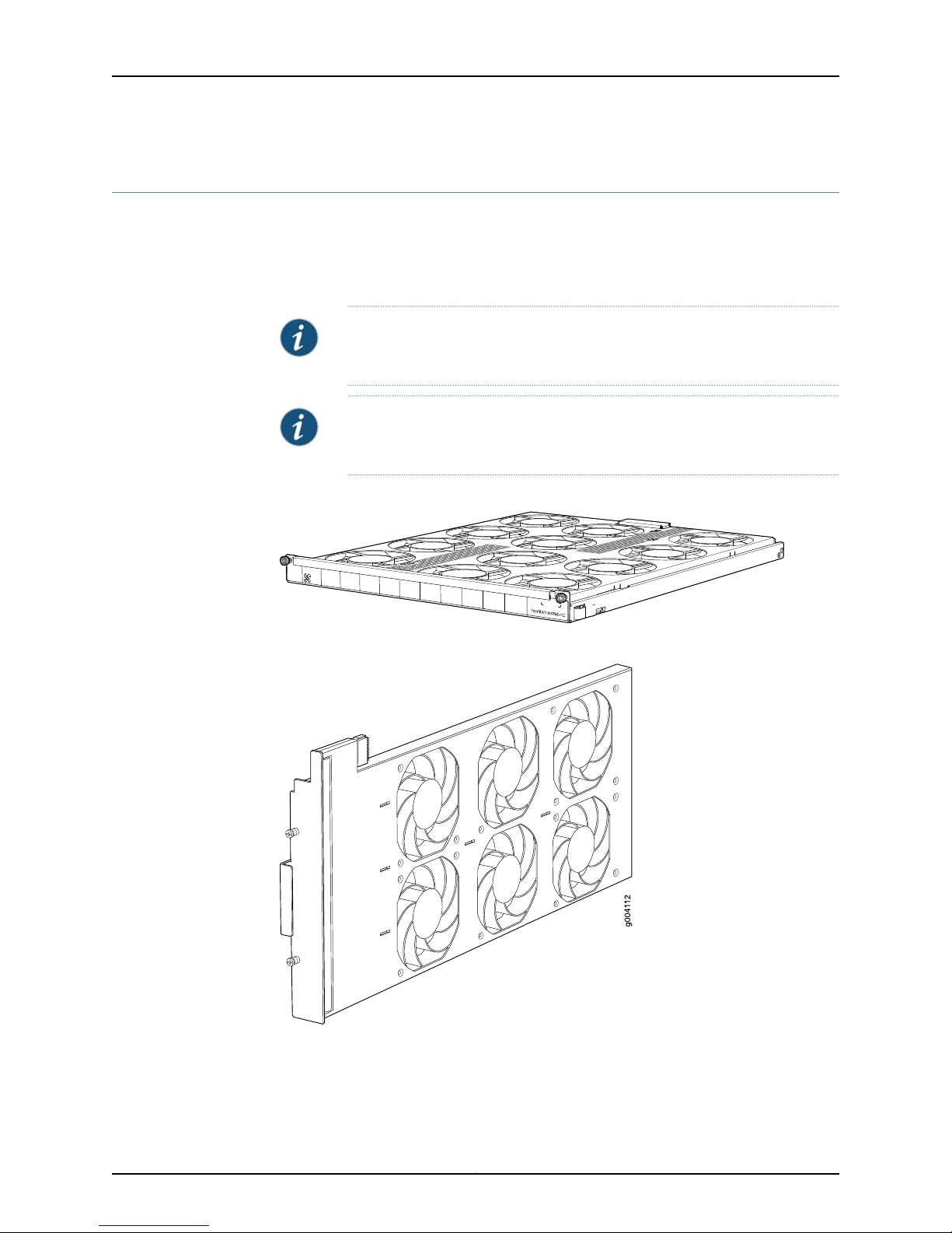
Fan Tray Upgrade Overview
The MX Series high-capacity fan trays satisfy cooling requirements for high-density DPCs
and MPCs, and must be upgraded for proper cooling (see Figure 1 on page 4, Figure 2
on page 4, and Figure 3 on page 5). Additionally, for the MX960 router, you must
upgrade both fan trays and the filter tray.
NOTE: Before upgrading, the MX Series router must be running Junos OS
Release 10.0 R1 or later to support high-capacity fan trays.
NOTE: To prevent overheating, install the replacement fan tray immediately
after removing the existing fan tray.
Figure 1: MX960 High-Capacity Fan Tray
Figure 2: MX480 High-Capacity Fan Tray
Copyright © 2010, Juniper Networks, Inc.4
Page 5
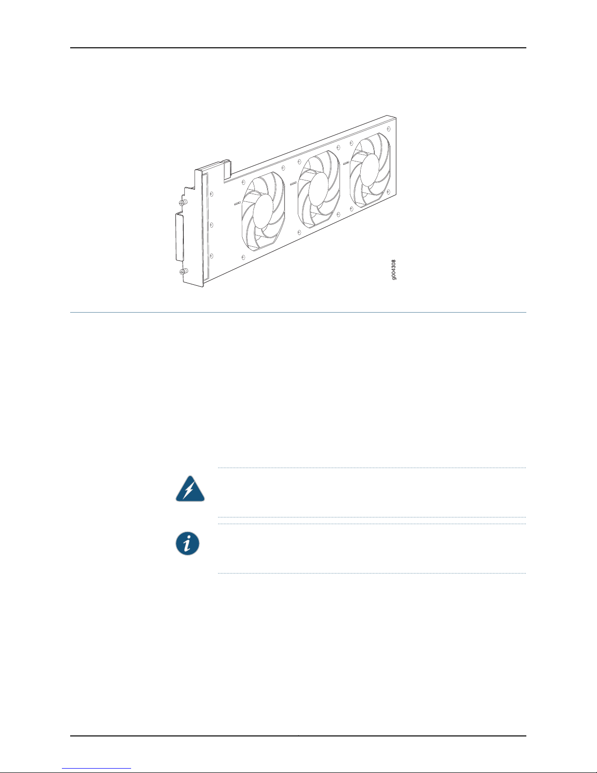
Figure 3: MX240 High-Capacity Fan Tray
Replacing the MX240 Fan Tray
Replacing the MX240 Fan Tray
To remove the fan tray (see Figure 4 on page 6 ):
1. Attachan electrostatic discharge (ESD) grounding strap to your bare wrist, and connect
the strap to an approved site ESD grounding point. See the instructions for your site.
2. Loosen the captive screws on the fan tray faceplate.
3. Grasp the fan tray handle and pull it out approximately 1 to 3 inches.
4. Press the latch located on the inside of the fan tray to release it from the chassis.
5. Place one hand under the fan tray to support it and pull the fan tray completely out
of the chassis.
WARNING: To avoid injury, keep tools and your fingers away from the fans
as you slide the fan tray out of the chassis. The fans might still be spinning.
NOTE: To prevent overheating, install the replacement fan tray immediately
after removing the existing fan tray.
5Copyright © 2010, Juniper Networks, Inc.
Page 6
Upgrading MX240, MX480, and MX960 3D Universal Edge Router Power Supplies and Fan Trays
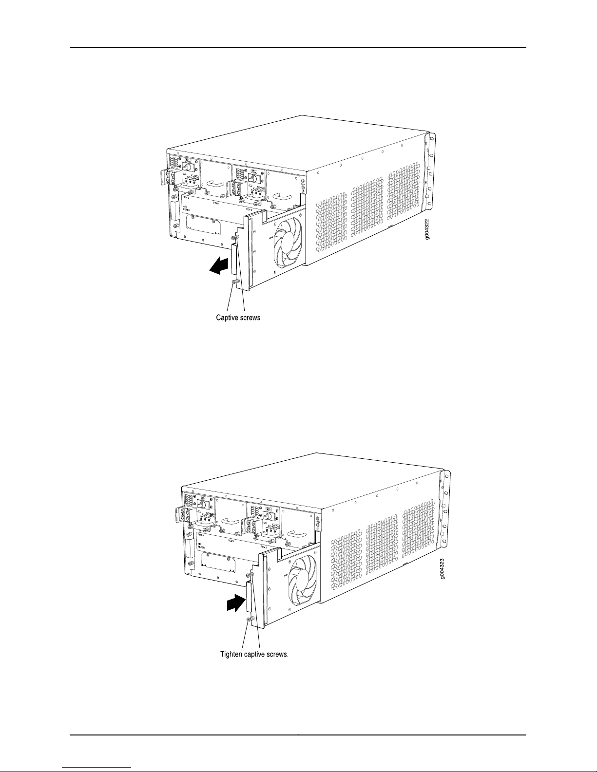
Figure 4: Removing the Fan Tray
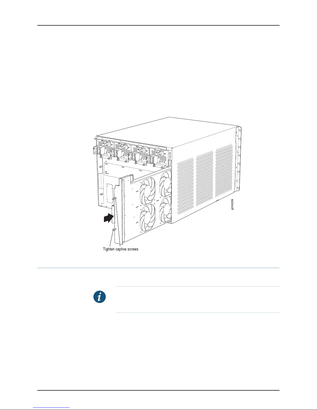
To install the fan tray (see Figure 5 on page 6):
1. Attachan electrostatic discharge (ESD) grounding strap to your bare wrist, and connect
the strap to one of the ESD points on the chassis.
2. Grasp the fan tray on each side and insert it straight into the chassis. Note the correct
orientation by the "this side up" label on the top surface of the fan tray.
3. Tighten the captive screws on the fan tray faceplate to secure it in the chassis.
Figure 5: Reinstalling a Fan Tray
Copyright © 2010, Juniper Networks, Inc.6
Page 7
Replacing the MX480 Fan Tray
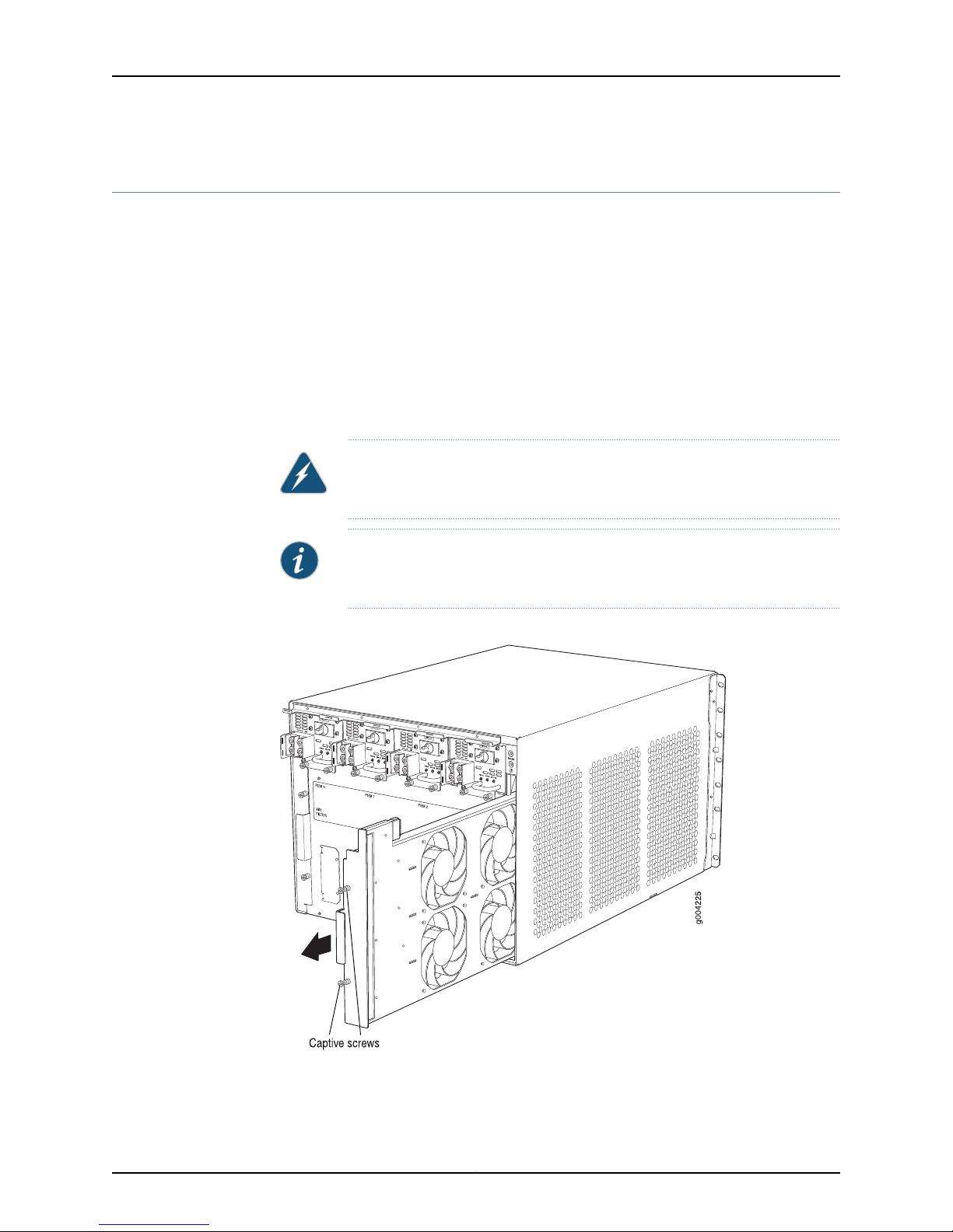
To remove the fan tray (see Figure 6 on page 7):
1. Attachan electrostatic discharge (ESD)grounding strap to your bare wrist and connect
the strap to an approved site ESD grounding point. See the instructions for your site.
2. Loosen the captive screws on the fan tray faceplate.
3. Grasp the fan tray handle and pull it out approximately 1 to 3 inches.
4. Press the latch located on the inside of the fan tray to release it from the chassis.
5. Place one hand under the fan tray to support it and pull the fan tray completely out
of the chassis.
WARNING: To avoid injury, keep tools and your fingers away from the fans
as you slide the fan tray out of the chassis. The fans might still be spinning.
Replacing the MX480 Fan Tray
NOTE: To prevent overheating, install the replacement fan tray immediately
after removing the existing fan tray.
Figure 6: Removing the Fan Tray
7Copyright © 2010, Juniper Networks, Inc.
Page 8
Upgrading MX240, MX480, and MX960 3D Universal Edge Router Power Supplies and Fan Trays
To install the fan tray (see Figure 7 on page 8):
1. Attachan electrostatic discharge (ESD) grounding strap to your bare wrist, and connect
the strap to one of the ESD points on the chassis.
2. Grasp the fan tray on each side, and insert it straight into the chassis. Note the correct
orientation by the "this side up" label on the top surface of the fan tray.
3. Tighten the captive screws on the fan tray faceplate to secure it in the chassis.
Figure 7: Reinstalling a Fan Tray
Replacing the MX960 Fan Trays
It is required to upgrade both MX960 fan trays, as well as the fan filter tray.
To remove the upper or lower fan tray:
1. Attachan electrostatic discharge (ESD) grounding strap to your bare wrist, and connect
the strap to one of the ESD points on the chassis.
2. Loosen the captive screw on each side of the fan tray faceplate.
3. Grasp both sides of the fan tray and pull it out approximately 1 to 3 inches.
NOTE: To prevent overheating, one fan tray should always be installed and
operational during the upgrade process.
Copyright © 2010, Juniper Networks, Inc.8
Page 9
OK
0
F
AIL
ONLINE
OK
1
F
AIL
ONLINE
OK
2
F
AIL
ONLINE
OK
3
F
AIL
ONLINE
OK
4
F
AIL
ONLINE
OK
5
F
AIL
ONLINE
OK
0
F
AIL
ONLINE
MASTER
ONLINE
OFFLINE
RE0
F
AN
PEM
1
0
0
1
2
3
RE1
OK
1
F
AIL
ONLINE
OK
7
F
AIL
ONLINE
OK
8
F
AIL
ONLINE
OK
9
F
AIL
ONLINE
OK
10
F
AIL
ONLINE
OK
1
1
F
AIL
ONLINE
OK
2
6
F
AIL
ONLINE
ACO/L
T
YELLO
WALARM
REDALARM
NC
NO
C
NC
NO
C
1
0
1
0
1
0
1
0
1
0
1
1
0
0
1
0
1
0
1
0
g004042
Replacing the MX960 Fan Trays
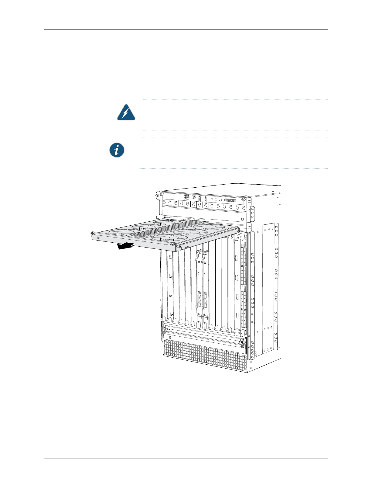
4. Press on the two latches located on the inside of the fan tray to release the fan tray
from the chassis.
5. Place one hand under the fan tray to support it, and pull the fan tray completely out
of the chassis.
WARNING: To avoid injury, keep tools and your fingers away from the fans
as you slide the fan tray out of the chassis. The fans might still be spinning.
NOTE: To prevent overheating, install the replacement fan tray immediately
after removing the existing fan tray.
Figure 8: Removing an Upper Fan Tray
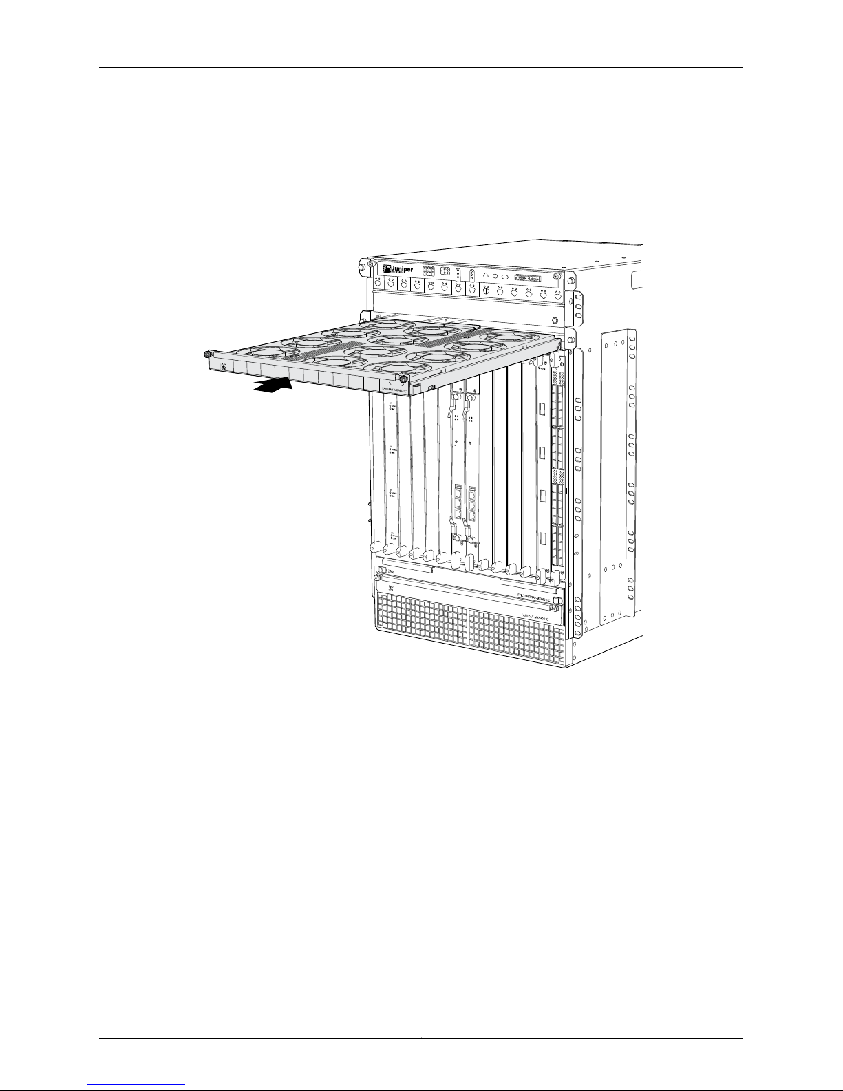
To install the fan trays (see Figure 5 on page 6 and Figure 9 on page 10):
1. Attachan electrostatic discharge (ESD) grounding strap to your bare wrist, and connect
the strap to one of the ESD points on the chassis.
2. Grasp the fan tray on each side, and insert it straight into the chassis. Note the correct
orientation by the "this side up" label on the top surface of the fan tray.
9Copyright © 2010, Juniper Networks, Inc.
Page 10
OK
0
FAIL
ONLINE
OK
1
FAIL
ONLINE
OK
2
FAIL
ONLINE
OK
3
FAIL
ONLINE
OK
4
FAIL
ONLINE
OK
5
FAIL
ONLINE
OK
0
FAIL
ONLINE
MASTER
ONLINE
OFFLINE
RE0
FAN
PEM
1
0
0
1
2
3
RE1
OK
1
FAIL
ONLINE
OK
7
FAIL
ONLINE
OK
8
FAIL
ONLINE
OK
9
FAIL
ONLINE
OK
10
FAIL
ONLINE
OK
11
FAIL
ONLINE
OK
2
6
FAIL
ONLINE
ACO/LT
YELLOWALARM
REDALARM
NC
NO
C
NC
NO
C
1
0
1
0
1
0
1
0
1
0
1
1
0
0
1
0
1
0
1
0
Upgrading MX240, MX480, and MX960 3D Universal Edge Router Power Supplies and Fan Trays
3. Tighten the captive screws on each side of the fan tray faceplate to secure it in the
chassis.
4. Lower the standard cable manager back into position, if necessary.
Figure 9: Installing an Upper Fan Tray
Copyright © 2010, Juniper Networks, Inc.10
Page 11
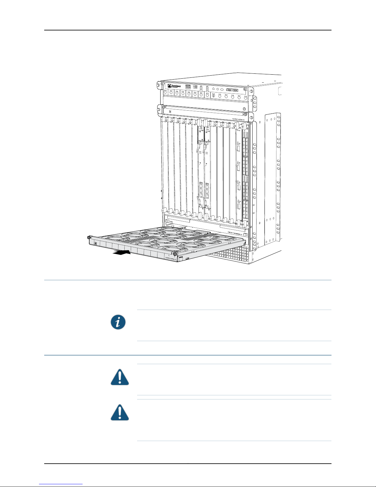
Figure 10: Installing a Lower Rear Fan Tray
OK
0
FAIL
ONLINE
OK
1
FAIL
ONLINE
OK
2
FAIL
ONLINE
OK
3
FAIL
ONLINE
OK
4
FAIL
ONLINE
OK
5
FAIL
ONLINE
OK
0
FAIL
ONLINE
MASTER
ONLINE
OFFLINE
RE0
FAN
PEM
1
0
0
1
2
3
RE1
OK
1
FAIL
ONLINE
OK
7
FAIL
ONLINE
OK
8
FAIL
ONLINE
OK
9
FAIL
ONLINE
OK
10
FAIL
ONLINE
OK
11
FAIL
ONLINE
OK
2
6
FAIL
ONLINE
ACO/LT
YELLOWALARM
REDALARM
NC
NO
C
NC
NO
C
1
0
1
0
1
0
1
0
1
0
1
1
0
0
1
0
1
0
1
0
g006002
Upgrading the MX960 Air Filter Tray
Upgrading the MX960 Air Filter Tray
For proper cooling, it is necessary to upgrade the fan filter tray in addition to both fan
trays.
Removing the MX960 Air Filter
NOTE: Mixing of high-capacity fan trays and the existing fan filter tray is not
supported.
CAUTION: Do not run the router for more than a few minutes without the air
filter in place.
CAUTION: Always keep the air filter in place while the router is operating,
except during replacement. Because the fans are very powerful, they could
pull small bits of wire or other materials into the router through the unfiltered
air intake. This could damage the router components.
11Copyright © 2010, Juniper Networks, Inc.
Page 12

Upgrading MX240, MX480, and MX960 3D Universal Edge Router Power Supplies and Fan Trays
To remove the air filter (see Figure 11 on page 12):
1. Attachan electrostatic discharge (ESD) grounding strap to your bare wrist, and connect
the strap to one of the ESD points on the chassis.
2. Unwrap any cables on the standard cable manager and remove the cables from the
tray. Arrange the cables so that they do not block the front of the cable manager and
tray, and secure them with temporary fasteners so that they are not supporting their
own weight as they hang from the connector.
NOTE: Removing the cables from the extended cable manager is not
necessary to access the air filter.
CAUTION: Do not let fiber-optic cable hang free from the connector. Do
not allow fastened loops of cable to dangle, which stresses the cable at
the fastening point.
3. Simultaneously pull the two releases labeled PULL on the standard cable manager.
Lift it up and outward to lock it in place to access the air filter.
4. Slide the air filter tray out of the chassis.
5. Lift the air filter out of the air filter tray.
Figure 11: Removing the Air Filter
Related
Documentation
Preventing Electrostatic Discharge Damage to an MX960 Router•
• Installing the MX960 Air Filter
• Maintaining the MX960 Air Filter
Installing the MX960 High-Capacity Tray and Filter
To install the air filter (see Figure 12 on page 13);
1. Attachan electrostatic discharge (ESD) grounding strap to your bare wrist, and connect
the strap to one of the ESD points on the chassis.
2. Ensure that the air filter is right side up.
3. Place the air filter into the air filter tray.
Copyright © 2010, Juniper Networks, Inc.12
Page 13

4. Insert the air filter tray into the chassis by sliding it straight into the chassis until it
stops.
5. Lower the cable manager back into position.
6. Rearrange the cables in the cable manager.
Figure 12: Installing the Air Filter
Fan Tray Power Requirements
Table 1: Fan Tray Power Requirements
Fan Tray Power Requirements
Power Supply Zone Overview
Unlike systems with previous MX960 AC supplies, the systems with MX Series
high-capacity power supplies are zoned. No current sharing between power supplies is
needed with the upgradedsystem because the redundancy changes from 3+1 per system
to 1+1 per zone. For MX960 AC configurations, two zones are present. Two adjacent
power supplies need to be installed in the chassis with two feeds attached.
To upgrade an MX960 AC router, remove one existing old power supply from either slot
0 or slot 3 (either far left or far right), and replace it with a high-capacity power supply.
Attach power feeds and power up the power supply. Remember to turn on both switches
while upgrading the MX960 AC power supply, that is, the one on the power supply and
the one on the Power Distribution Module (PDU). Continue by removing an adjacent
existing power supply, and replacing it with a high-capacity power supply.
The minimum number of power supplies must be present in the router at all times.
Power Requirement (Watts)Component
85MX240 high-capacity fan tray
160MX480 high-capacity fan tray
320MX960 high-capacity fan tray
Table 2: Minimum Required Number of Power Supplies
ConfigurationRouter Model
Minimum Required Number of Power
Supplies
1AC – high lineMX240
13Copyright © 2010, Juniper Networks, Inc.
Page 14

Upgrading MX240, MX480, and MX960 3D Universal Edge Router Power Supplies and Fan Trays
Table 2: Minimum Required Number of Power Supplies (continued)
2AC – low lineMX240
1 (only 1 zone)DCMX240
2AC – high lineMX480
3AC – low lineMX480
1 minimum per zoneDCMX480
1 minimum per zoneACMX960
1 minimum per zoneDCMX960
Upgrading the MX240 and MX480 AC Power Supplies
NOTE: Junos OS Release 10.0 R2 is required to support the MX240 and
MX480 AC and DC high capacity power supplies, and the MX960 AC
high-capacity power supplies. Junos OS Release10.2 R1 is required to support
the MX960 DC high-capacity power supplies.
NOTE: During the upgrade process, the MX Series router can simultaneously
run existing and high-capacity power supplies. However, it is recommended
to upgrade all power supplies to high-capacity power supplies.
Removing the MX240 and MX480 AC Power Supplies
NOTE: The minimum number of power supplies must be present in the router
at all times.
CAUTION: To maintain proper cooling and prevent thermal shutdown of the
operating power supply unit, each power supply slot must contain either a
power supply or a blank panel. If you remove a power supply, you must install
a replacement power supply or a blank panel shortly after the removal.
NOTE: After powering off a power supply, wait at least 60 seconds before
turning it back on.
Copyright © 2010, Juniper Networks, Inc.14
Page 15

Installing the MX240 and MX480 AC High-Capacity Power Supplies
To remove an AC power supply (see Figure 19 on page 24):
1. Switch off the dedicated customer site circuit breaker for the power supply, and
remove the power cord from the AC power source. Follow the instructions for your
site.
2. Attach an electrostatic discharge (ESD) grounding strap to your bare wrist, and connect
the strap to one of the ESD points on the chassis.
3. Move the AC input switch next to the appliance inlet on the power supply to the off
(O) position.
4. Remove the power cord from the power supply.
5. Unscrew the captive screws on the bottom edge of the power supply.
6. Pull the power supply straight out of the chassis.
Installing the MX240 and MX480 AC High-Capacity Power Supplies
NOTE: Upgrade adjacent power supplies; remove an existing power supply,
then install the high-capacity power supply.
NOTE: During the upgrade process, you can simultaneously run existing and
high-capacity power supplies. However, it is recommended to upgrade all
power supplies to high-capacity power supplies.
To install an AC power supply (see Figure 13 on page 16):
1. Attachan electrostatic discharge (ESD) grounding strap to your bare wrist, and connect
the strap to one of the ESD points on the chassis.
2. Move the AC input switch next to the appliance inlet on the power supply to the off (O)
position.
3. Using both hands, slide the power supply straight into the chassis until the power
supply is fully seated in the chassis slot. The power supply faceplate should be flush
with any adjacent power supply faceplate or blank installed in the power supply slot.
4. Tighten both captive screws at the bottom of the power supply.
5. Attach the power cord to the power supply.
6. Attach the power cord to the AC power source, and switch on the dedicated customer
site circuit breaker. Follow the instructions for your site.
7. Move the AC input switch next to the appliance inlet on the power supply to the on
(|) position and observe the status LEDs on the power supply faceplate. If the power
supply is correctly installed and functioning normally, the AC OK and DC OK LEDs light
steadily and the PS FAIL LED is not lit.
15Copyright © 2010, Juniper Networks, Inc.
Page 16

Upgrading MX240, MX480, and MX960 3D Universal Edge Router Power Supplies and Fan Trays
Figure 13: Installing an AC Power Supply
Upgrading the MX240 and MX480 DC Power Supplies
Removing the MX240 and MX480 DC Power Supplies
NOTE: The minimum number of power supplies must be present in the router
at all times.
WARNING: Before performing DC power procedures, ensure that power is
removed from the DC circuit. To ensure that all power is off, locate the circuit
breaker on the panel board that services the DC circuit, switch the circuit
breaker to the off position, and tape the switch handle of the circuit breaker
in the off position.
CAUTION: To maintain proper cooling and prevent thermal shutdown of the
operating power supply unit, each power supply slot must contain either a
power supply or a blank panel. If you remove a power supply, you must install
a replacement power supply or a blank panel shortly after the removal.
NOTE: After powering off a power supply, wait at least 60 seconds before
turning it back on.
Copyright © 2010, Juniper Networks, Inc.16
Page 17

Setting the MX240 and MX480 DC High-Capacity Power Supply Input Mode Switch
To remove a DC power supply (see Figure 14 on page 17):
1. Switch off the dedicated customer site circuit breaker for the power supply being
removed. Follow your site's procedures for ESD.
2. Make sure that the voltage across the DC power source cable leads is 0 V and that
there is no chance that the cables might become active during the removal process.
3. Attach an electrostaticdischarge (ESD) grounding strap to your bare wrist, and connect
the strap to one of the ESD points on the chassis.
4. Move the DC circuit breaker on the DC power supply faceplate to the off (O) position.
5. Remove the clear plastic cover protecting the terminal studs on the faceplate.
6. Remove the nut and washer from each of the terminal studs. (Use a 7/16-in. [11-mm]
nut driver or socket wrench.)
7. Remove the cable lugs from the terminal studs.
8. Loosen the captive screws on the bottom edge of the power supply faceplate.
9. Carefully move the power cables out of the way.
10. Pull the power supply straight out of the chassis.
Figure 14: Removing a DC Power Supply from the Router
Setting the MX240 and MX480 DC High-Capacity Power Supply Input Mode Switch
NOTE: Move the input switch to 0 for 60 A input and position 1 for 70 A input.
NOTE: Do not set the input mode switch if the power supply is installed in
the chassis. If the power supply is already installed,you must removeit before
setting the input mode switch.
17Copyright © 2010, Juniper Networks, Inc.
Page 18

g004725
Upgrading MX240, MX480, and MX960 3D Universal Edge Router Power Supplies and Fan Trays
To set the input mode switch:
1. Using a screwdriver, loosen the captive screw holding the metal cover over the input
mode switch.
2. Rotate the metal cover away from the input mode switch to expose the switch.
3. Check the setting of the input mode switch.
4. Use a sharp, nonconductive object to slide the switch to the desired position.
Figure 15: MX 240 DC and MX480 DC High-Capacity Power Supply Input
Mode Switch
CAUTION: Do not use a pencil, because fragments can break off and cause
damage to the power supply.
5. Rotate the metal cover over the input mode switch, and use a screwdriver to tighten
the captive screw.
Copyright © 2010, Juniper Networks, Inc.18
Page 19

Installing the MX240 and MX480 DC High-Capacity Power Supplies
Installing the MX240 and MX480 DC High-Capacity Power Supplies
NOTE: During the upgrade process, you can simultaneously run existing and
high-capacity power supplies. However, it is recommended to upgrade all
power supplies to high-capacity power supplies.
WARNING: Before performing DC power procedures, ensure that power is
removed from the DC circuit. To ensure that all power is off, locate the circuit
breaker on the panel board that services the DC circuit, switch the circuit
breaker to the off position, and tape the switch handle of the circuit breaker
in the off position.
To install a DC power supply (see Figure 16 on page 21):
1. Ensure that the voltage across the DC power source cable leads is 0 V and that there
is no chance that the cable leads might become active during installation.
2. Attach an electrostatic discharge (ESD) grounding strap to your bare wrist, and connect
the strap to one of the ESD points on the chassis.
3. Move the DC circuit breaker on the power supply faceplate to the off (O) position.
4. Using both hands, slide the power supply straight into the chassis until the power
supply is fully seated in the chassis slot. The power supply faceplate should be flush
with any adjacent power supply faceplate or blank installed in the power supply slot.
5. Tighten the captive screws on the lower edge of the power supply faceplate.
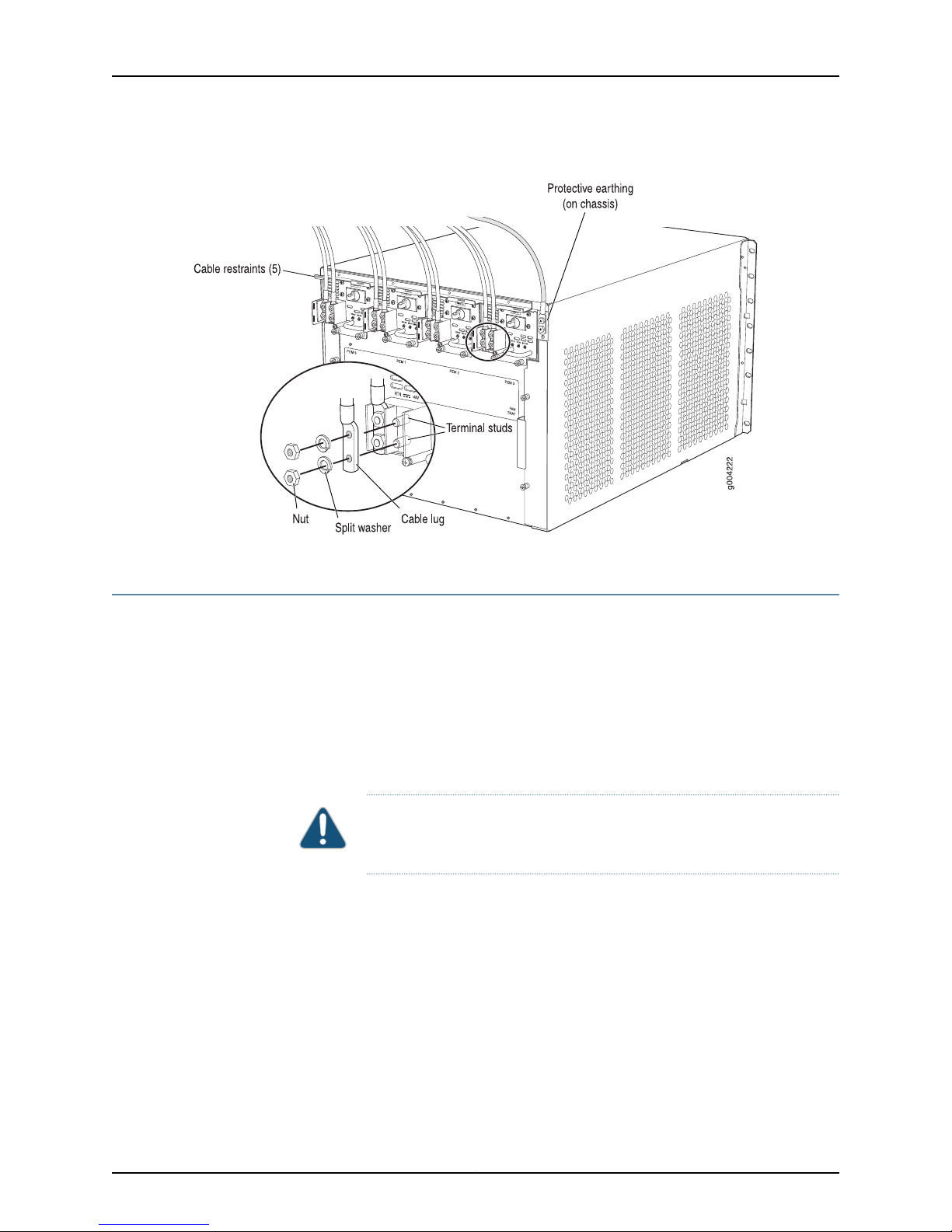
6. Remove the clear plastic cover protecting the terminal studs on the faceplate.
7. Remove the nut and washer from each of the terminal studs.
8. Secure each power cable lug to the terminal studs, first with the flat washer, then
with the split washer, and then with the nut (see Figure 17 on page 22). Apply between
23 lb-in. (2.6 Nm) and 25 lb-in. (2.8 Nm) of torque to each nut. Do not overtighten the
nut. (Use a 7/16-in. [11 mm] torque-controlled driver or socket wrench.)
a. Secure the positive (+) DC source power cable lug to the RTN (return) terminal.
b. Secure the negative (–) DC source power cable lug to the –48V (input) terminal.
CAUTION: Ensure that each power cablelug seats flush against the surface
of the terminal block as you are tightening the nuts. Ensure that each nut
is properly threaded onto the terminal stud. The nut should be able to spin
freely with your fingers when it is first placed onto the terminal stud.
Applying installation torque to the nut when improperly threaded may
result in damage to the terminal stud.
19Copyright © 2010, Juniper Networks, Inc.
Page 20

Upgrading MX240, MX480, and MX960 3D Universal Edge Router Power Supplies and Fan Trays
CAUTION: The maximum torque rating of the terminal studs on the DC
power supply is 36 lb-in. (4.0 Nm). The terminal studs may be damaged
if excessive torque is applied. Use only a torque-controlled driver or socket
wrench to tighten nuts on the DC power supply terminal studs.
CAUTION: You must ensure that power connections maintain the proper
polarity. The power source cables might be labeled (+) and (–) to indicate
their polarity. There is no standard color coding for DC power cables. The
color coding used by the external DC power source at your site determines
the color coding for the leads on the power cables that attach to the
terminal studs on each power supply.
NOTE: The DC power supplies in PEM0 and PEM1 must be powered by
dedicated power feeds derived from feed A, and the DC power supplies
in PEM2 and PEM3 must be powered by dedicated power feeds derived
from feed B. This configurationprovides the commonly deployed A/B feed
redundancy for the system.
NOTE: For information about connecting to DC power sources, see DC
Power Supply Electrical Specifications for the MX480 Router.
9. Replace the clear plastic cover over the terminal studs on the faceplate.
10. Route the power cables along the cable restraint toward the left or right corner of the
chassis. If needed to hold the power cables in place, thread plastic cable ties, which
you must provide, through the openings on the cable restraint.
11. Verify that the power cabling is correct, that the cables are not touching or blocking
access to router components, and that they do not drape where people could trip on
them.
12. Switch on the dedicated customer site circuit breakers. Follow your site's procedures
for safety and ESD.
Verify that the INPUT OK LED on the power supply is lit green.
13. On each of the DC power supplies, switch the DC circuit breaker to the center position
before moving it to the on (—) position.
NOTE: The circuit breaker may bounce back to the off (O) position if you
move the breaker too quickly.
Copyright © 2010, Juniper Networks, Inc.20
Page 21

Installing the MX240 and MX480 DC High-Capacity Power Supplies
Observe the status LEDs on the power supply faceplate. If the power supply is correctly
installed and functioning normally, the PWR OK, BRKR ON, and INPUT OK LEDs light
green steadily.
NOTE: If more than one power supply is being installed, turn on all power
supplies at the same time.
NOTE: An SCB must be present for the PWR OK LED to go on.
Figure 16: Installing a DC Power Supply in the Router
21Copyright © 2010, Juniper Networks, Inc.
Page 22
Upgrading MX240, MX480, and MX960 3D Universal Edge Router Power Supplies and Fan Trays
Figure 17: Connecting DC Power to the Router
Upgrading the MX960 AC Power Supplies Overview
To upgrade the MX960 AC power supplies:
1. Remove one existing old power supply from either slot 0 or slot 3 (either far left or far
right), and replace it with a high-capacity power supply.
2. On the high-capacity power supply, rotate the metal cover away from the input mode
switch to expose the switch.
3. Move the input mode switch to position 0 for one feed or position 1 for two feeds (see
Figure 18 on page 23).
CAUTION: Do not use a pencil, because fragments can break off and cause
damage to the power supply.
4. Attach power feeds and power up the power supply.
5. Remember to turn on both switches while upgrading the MX960 AC power supply
(the one on the power supply and the one on the Power Distribution Module [PDM]).
6. Continue by removing an adjacent existing power supply and replacing it with a
high-capacity power supply.
Copyright © 2010, Juniper Networks, Inc.22
Page 23
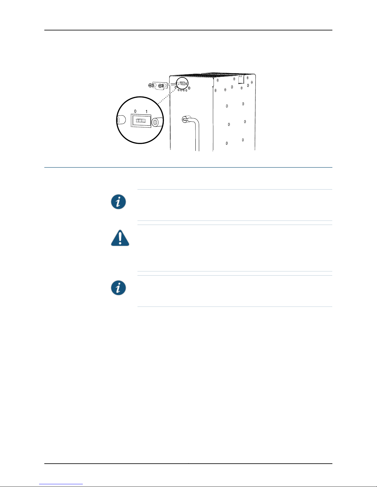
Figure 18: MX960 AC Power Input Mode Switch
g004714
Removing the MX960 AC Power Supplies
Before you remove a power supply, be aware of the following:
NOTE: The minimum number of power supplies must be present in the router
at all times.
Removing the MX960 AC Power Supplies
CAUTION: To maintain proper cooling and prevent thermal shutdown of the
operating power supply unit, each power supply slot must contain either a
power supply or a blank panel. If you remove a power supply, you must install
a replacement power supply or a blank panel shortly after the removal.
NOTE: After powering off a power supply, wait at least 60 seconds before
turning it back on.
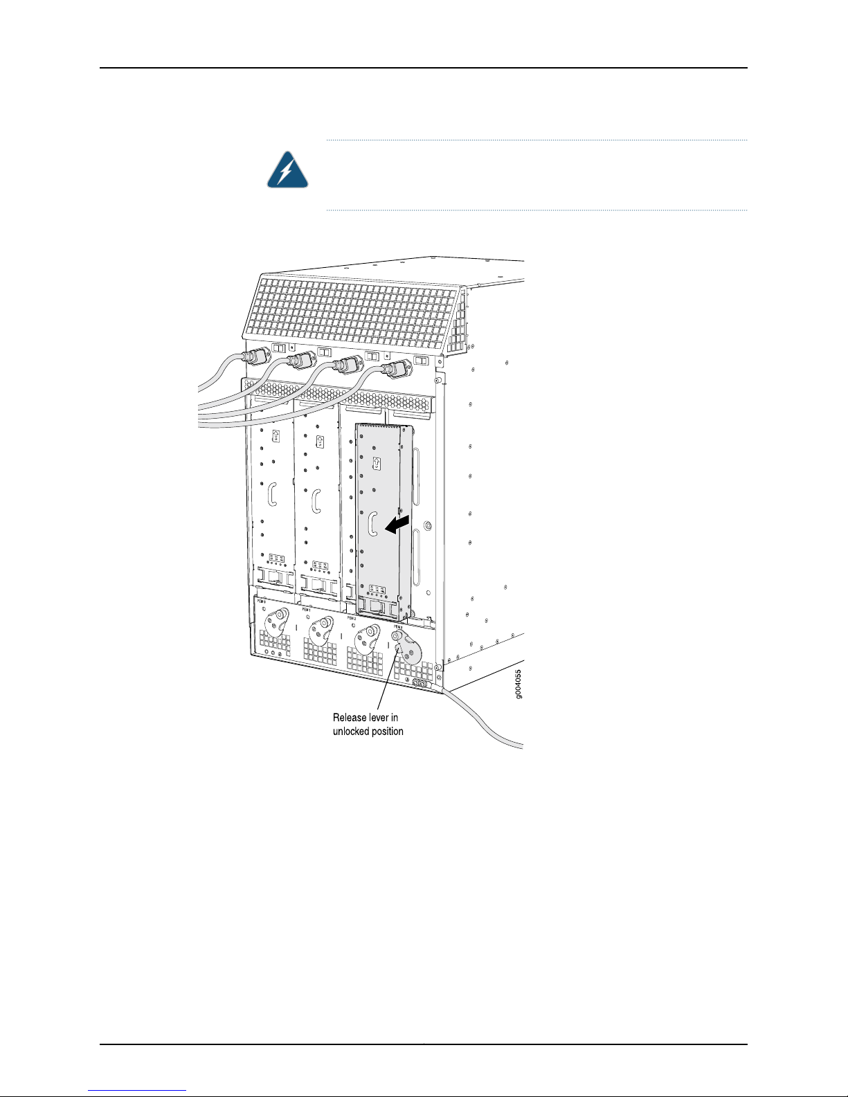
To remove an AC power supply (see Figure 19 on page 24):
1. Switch off the dedicated customer site circuit breaker for the power supply, and
remove the power cord from the AC power source. Follow the ESD and disconnection
instructions for your site.
2. Move the AC input switch in the chassis above the power supply to the off (O) position.
3. While grasping the handle on the power supply faceplate with one hand, use your
other hand to pull the spring-loaded locking pin in the release lever away from the
chassis and turn the release lever counterclockwise until it stops.
4. Let go of the locking pin in the release lever. Ensure that the pin is seated inside the
corresponding hole in the chassis.
5. Pull the power supply straight out of the chassis.
23Copyright © 2010, Juniper Networks, Inc.
Page 24
Upgrading MX240, MX480, and MX960 3D Universal Edge Router Power Supplies and Fan Trays
WARNING: Do not touch the power connector on the top of the power
supply. It can contain dangerous voltages.
Figure 19: Removing an MX960 AC Power Supply
Copyright © 2010, Juniper Networks, Inc.24
Page 25

Installing the MX960 AC High-Capacity Power Supplies
Installing the MX960 AC High-Capacity Power Supplies
NOTE: During the upgrade process, you can simultaneously run existing and
high- capacity power supplies. However, it is recommended to upgrade all
power supplies to high-capacity power supplies.
To install an AC power supply (see Figure 13 on page 16):
1. Move the AC input switch in the chassis above the empty power supply slot to the off
(O) position.
2. Ensure that the release lever below the empty power supply slot is locked in the
counterclockwise position (see Figure 13 on page 16).
If necessary, pull the spring-loaded locking pin in the release lever away from the
chassis and turn the release lever counterclockwise until it stops. Let go of the locking
pin in the release lever. Ensure that the pin is seated inside the corresponding hole in
the chassis.
3. Using both hands, slide the power supply straight into the chassis until the power
supply is fully seated in the chassis slot. The power supply faceplate should be flush
with any adjacent power supply faceplates.
The small tab on the metal housing that is controlled by the release lever must be
inside of the corresponding slot at the bottom of the power supply (see Figure 20 on
page 26). This tab is used to pull the power supply down in the chassis slot, prior to
removing the power supply.
4. While firmly pushing the handle on the power supply faceplate with one hand, use
your other hand to pull the spring-loaded locking pin in the release lever away from
the chassis and turn the release lever clockwise until it stops.
5. Let go of the locking pin in the release lever. Ensure that the pin is seated inside the
corresponding hole in the chassis.
6. Move the AC input switch in the chassis above the power supply to the on (—) position
and observe the status LEDs on the power supply faceplate. If the power supply is
correctly installed and functioning normally, the AC OK and DC OK LEDs light steadily,
and the PS FAIL LED is not lit.
25Copyright © 2010, Juniper Networks, Inc.
Page 26

g004700
AC-1OK
AC-2OK
DCOK
PSFAIL
AC-1OK
AC-2OK
DCOK
PSFAIL
AC-1OK
AC-2OK
DCOK
PSFAIL
AC-1OK
AC-2OK
DCOK
PSFAIL
Protective earthing
ESD point
Power supply
ejectors
AC Power
supplies
Air exhaust
Air exhaust
Upgrading MX240, MX480, and MX960 3D Universal Edge Router Power Supplies and Fan Trays
Figure 20: Installing an AC Power Supply
NOTE: The MX960 DC power supplies protrude approximately 2 inches from
the back of the chassis. See Figure 21 on page 27.
Copyright © 2010, Juniper Networks, Inc.26
Page 27

Rear of chassis
Front of chassis
17.4"
(44.2 cm)
24.5"
(62.2 cm)
g003496
Front-mounting flange
19.2"
(48.7 cm)
24" (61 cm)
clearance required
30" (76.2 cm)
clearance recommended
Standard cable manager
34.8"
(88.4 cm)
Upgrading the MX960 DC Power Supplies Overview
Figure 21: MX960 Chassis Dimension with High-Capacity DC Power
Supplies Installed
Upgrading the MX960 DC Power Supplies Overview
To upgrade the MX960 DC power supplies:
1. Remove one existing old power supply from either slot 0 or slot 3 (either far left or far
right), and replace it with a high-capacity power supply.
2. On the high-capacity power supply, rotate the metal cover away from the input mode
switch to expose the switch.
3. Move the input mode switch to position 0 for one feed or position 1 for two feeds.
NOTE: For a fully redundant configuration in two-feed mode, 8 feeds are
required. For a non-redundant configuration, 4 feeds are required.
27Copyright © 2010, Juniper Networks, Inc.
Page 28

Upgrading MX240, MX480, and MX960 3D Universal Edge Router Power Supplies and Fan Trays
Figure 22: MX960 DC High-Capacity Power Supply Front View
CAUTION: Do not use a pencil, because fragments can break off and cause
damage to the power supply.
4. Attach power feeds and power up the power supply.
5. Continue by removing an adjacent existing power supply and replacing it with a
high-capacity power supply.
Removing an MX960 DC Power Supply
Before you remove a power supply, be aware of the following:
NOTE: The minimum number of power supplies must be present in the router
at all times.
WARNING: Before performing DC power procedures, ensure that power is
removed from the DC circuit. To ensure that all power is off, locate the circuit
breaker on the panel board that services the DC circuit, switch the circuit
breaker to the off position, and tape the switch handle of the circuit breaker
in the off position.
CAUTION: To maintain proper cooling and prevent thermal shutdown of the
operating power supply unit, each power supply slot must contain either a
Copyright © 2010, Juniper Networks, Inc.28
Page 29

Removing an MX960 DC Power Supply
power supply or a blank panel. If you remove a power supply, you must install
a replacement power supply or a blank panel shortly after the removal.
NOTE: After powering off a power supply, wait at least 60 seconds before
turning it back on.
To remove a DC power supply (see Figure 14 on page 17):
1. Switch off the dedicated customer site circuit breaker for the power supply being
removed. Follow your site's procedures for ESD.
2. Make sure that the voltage across the DC power source cable leads is 0 V and that
there is no chance that the cables might become active during the removal process.
3. Verify that the INPUT OK LEDs on the power supply to be removed are not lit.
4. Attach an electrostatic discharge (ESD) grounding strap to your bare wrist, and connect
the strap to one of the ESD points on the chassis.
5. Move the DC circuit breaker on the power supply faceplate to the off (O) position.
6. Remove the clear plastic cover protecting the terminal studs on the faceplate.
7. Remove the nut and washer from each of the terminal studs. (Use a 7/16-in.
[11-mm] nut driver or socket wrench.)
8. Remove the cable lugs from the terminal studs.
9. Loosen the captive screw on the cable restraint on the lower edge of the power supply
faceplate.
10. Carefully move the power cables out of the way.
11. While grasping the handle on the power supply faceplate with one hand, use your
other hand to pull the spring-loaded locking pin in the release lever away from the
chassis and turn the release lever counterclockwise until it stops.
12. Let go of the locking pin in the release lever. Ensure that the pin is seated inside the
corresponding hole in the chassis.
13. Pull the power supply straight out of the chassis.
WARNING: Do not touch the power connector on the top of the power
supply. It can contain dangerous voltages.
29Copyright © 2010, Juniper Networks, Inc.
Page 30

Upgrading MX240, MX480, and MX960 3D Universal Edge Router Power Supplies and Fan Trays
Figure 23: Removing a DC Power Supply from the MX960 Router
Installing the MX960 DC High-Capacity Power Supplies
To install a DC power supply (see Figure 16 on page 21):
1. Ensure that the voltage across the DC power source cable leads is 0 V and that there
is no chance that the cable leads might become active during installation.
2. Attach an electrostatic discharge (ESD) grounding strap to your bare wrist, and connect
the strap to one of the ESD points on the chassis.
3. Move the switch on the power supply faceplate to the off (O) position.
WARNING: Before performing DC power procedures, ensure that power is
removed from the DC circuit. To ensure that all power is off, locate the circuit
breaker on the panel board that services the DC circuit, switch the circuit
breaker to the off position, and tape the switch handle of the circuit breaker
in the off position.
Copyright © 2010, Juniper Networks, Inc.30
Page 31

Installing the MX960 DC High-Capacity Power Supplies
4. Ensure that the release lever below the empty power supply slot is locked in the
counterclockwise position (see Figure 16 on page 21).
If necessary, pull the spring-loaded locking pin in the release lever away from the
chassis and turn the release lever counterclockwise until it stops. Let go of the locking
pin in the release lever. Ensure that the pin is seated inside the corresponding hole in
the chassis.
5. Using both hands, slide the power supply straight into the chassis until the power
supply is fully seated in the chassis slot.
The small tab on the metal housing that is controlled by the release lever must be
inside of the corresponding slot at the bottom of the power supply (see Figure 16 on
page 21). This tab is used to pull the power supply down in the chassis slot, prior to
removing the power supply.
6. While firmly pushing the handle on the power supply faceplate with one hand, use
your other hand to pull the spring-loaded locking pin in the release lever away from
the chassis and turn the release lever clockwise until it stops.
7. Let go of the locking pin in the release lever. Ensure that the pin is seated inside the
corresponding hole in the chassis.
8. Remove the cover protecting the terminal studs on the faceplate.
9. Remove the nut and washer from each of the terminal studs.
10. Secure each power cable lug to the terminal studs, first with the split washer, then
with the nut. Apply between 23 lb-in. (2.6 Nm) and 25 lb-in. (2.8 Nm) of torque to
each nut (see Figure 17 on page 22). Do not overtighten the nut. (Use a 7/16-in. [11-mm]
torque-controlled driver or socket wrench.)
a. Attach the positive (+) DC source power cable lug to the RTN (return) terminal.
b. Attach the negative (–) DC source power cable lug to the –48V (input) terminal.
CAUTION: Ensure that each power cablelug seats flush against the surface
of the terminal block as you are tightening the nuts. Ensure that each nut
is properly threaded onto the terminal stud. The nut should be able to spin
freely with your fingers when it is first placed onto the terminal stud.
Applying installation torque to the nut when improperly threaded may
result in damage to the terminal stud.
CAUTION: The maximum torque rating of the terminal studs on the DC
power supply is 36 lb-in. (4.0 Nm). The terminal studs may be damaged
if excessive torque is applied. Use only a torque-controlled driver or socket
wrench to tighten nuts on the DC power supply terminal studs.
31Copyright © 2010, Juniper Networks, Inc.
Page 32

Upgrading MX240, MX480, and MX960 3D Universal Edge Router Power Supplies and Fan Trays
CAUTION: You must ensure that power connections maintain the proper
polarity. The power source cables might be labeled (+) and (–) to indicate
their polarity. There is no standard color coding for DC power cables. The
color coding used by the external DC power source at your site determines
the color coding for the leads on the power cables that attach to the
terminal studs on each power supply.
NOTE: The DC power supplies in slots PEM0 and PEM1 must be powered
by dedicated power feeds derived from feed A, and the DC power supplies
in PEM2 and PEM3 must be powered by dedicated power feeds derived
from feed B. This configurationprovides the commonly deployed A/B feed
redundancyfor the system.For information about connectingto DC power
sources, see DC Power Supply Electrical Specifications for the MX960
Router.
11. Loosen the captive screw on the cable restraint on the lower edge of the power supply
faceplate.
12. Route the positive and negative DC power cables through the left and right sides of
the cable restraint.
13. Tighten the cable restraint captive screw to hold the power cables in place.
14. Replace the clear plastic cover over the terminal studs on the faceplate.
15. Verifythat the power cabling is correct, that the cables are not touching, and that they
do not block access to router components or drape where people could trip on them.
16. Switch on the dedicated customer site circuit breaker.
17. Verify that the INPUT OK LED on the power supply is lit steadily.
18. On each of the DC power supplies, move the switch to the on (|) position.
NOTE: The switch may bounce back to the off (O) position if you move
the breaker too quickly.
19. Verify that the DC OK LED is lit steadily.
Copyright © 2010, Juniper Networks, Inc.32
Page 33

JUNOS Documentation and Release Notes
Figure 24: Connecting DC Power to the MX960 Router
NOTE: The MX960 DC power supplies protrude approximately5 inches from
the back of the chassis.
JUNOS Documentation and Release Notes
For a list of related JUNOS documentation, see
http://www.juniper.net/techpubs/software/junos/ .
If the information in the latest release notes differs from the information in the
documentation, follow the JUNOS Release Notes.
To obtain the most current version of all Juniper Networks®technical documentation,
see the product documentation page on the Juniper Networks website at
http://www.juniper.net/techpubs/.
Requesting Technical Support
Technical product support is availablethrough the Juniper NetworksTechnical Assistance
Center (JTAC). If you are a customer with an active J-Care or JNASC support contract,
or are covered under warranty, and need postsales technical support, you can access
our tools and resources online or open a case with JTAC.
•
JTAC policies—For a complete understanding of our JTAC procedures and policies,
review the JTAC User Guide located at
http://www.juniper.net/us/en/local/pdf/resource-guides/7100059-en.pdf .
33Copyright © 2010, Juniper Networks, Inc.
Page 34

Upgrading MX240, MX480, and MX960 3D Universal Edge Router Power Supplies and Fan Trays
•
Product warranties—For product warranty information, visit
http://www.juniper.net/support/warranty/ .
•
JTAC Hours of Operation —The JTAC centers have resources available 24 hours a day,
7 days a week, 365 days a year.
Self-Help Online Tools and Resources
For quick and easy problem resolution, Juniper Networks has designed an online
self-service portal called the Customer Support Center (CSC) that provides you with the
following features:
•
Find CSC offerings: http://www.juniper.net/customers/support/
•
Find product documentation: http://www.juniper.net/techpubs/
•
Find solutions and answer questions using our Knowledge Base: http://kb.juniper.net/
•
Download the latest versions of software and review release notes:
http://www.juniper.net/customers/csc/software/
•
Search technical bulletins for relevant hardware and software notifications:
https://www.juniper.net/alerts/
•
Join and participate in the Juniper Networks Community Forum:
http://www.juniper.net/company/communities/
•
Open a case online in the CSC Case Management tool: http://www.juniper.net/cm/
To verify service entitlement by product serial number,use our Serial Number Entitlement
(SNE) Tool: https://tools.juniper.net/SerialNumberEntitlementSearch/
Opening a Case with JTAC
You can open a case with JTAC on the Web or by telephone.
•
Use the Case Management tool in the CSC at http://www.juniper.net/cm/ .
•
Call 1-888-314-JTAC (1-888-314-5822 toll-free in the USA, Canada, and Mexico).
For international or direct-dial options in countries without toll-free numbers, visit us at
http://www.juniper.net/support/requesting-support.html
Revision History
December 2010—Added note regarding required feeds for MX960 DC high-capacity
power supplies.
August 2010—Added MX960 DC high-capacity power supply content.
April 2010—Initial release.
Copyright © 2010, Juniper Networks, Inc. All rights reserved.
Juniper Networks, Junos, Steel-Belted Radius, NetScreen, and ScreenOS are registered trademarks of Juniper Networks, Inc. in the United
States and other countries. The Juniper Networks Logo, the Junos logo, and JunosE are trademarks of Juniper Networks, Inc. All other
trademarks, service marks, registered trademarks, or registered service marks are the property of their respective owners.
Copyright © 2010, Juniper Networks, Inc.34
Page 35

Requesting Technical Support
Juniper Networks assumes no responsibility for any inaccuracies in this document. Juniper Networks reserves the right to change, modify,
transfer, or otherwise revise this publication without notice.
Products made or sold by Juniper Networks or components thereof might be covered by one or more of the following patents that are
owned by or licensed to Juniper Networks: U.S. Patent Nos. 5,473,599, 5,905,725, 5,909,440, 6,192,051, 6,333,650, 6,359,479, 6,406,312,
6,429,706, 6,459,579, 6,493,347, 6,538,518, 6,538,899, 6,552,918, 6,567,902, 6,578,186, and 6,590,785.
35Copyright © 2010, Juniper Networks, Inc.
 Loading...