

Page 1

MX480 Universal Routing Platform
Published
2020-11-21
Hardware Guide
Page 2

Juniper Networks, Inc.
1133 Innovation Way
Sunnyvale, California 94089
USA
408-745-2000
www.juniper.net
Juniper Networks, the Juniper Networks logo, Juniper, and Junos are registered trademarks of Juniper Networks, Inc. in
the United States and other countries. All other trademarks, service marks, registered marks, or registered service marks
are the property of their respective owners.
Juniper Networks assumes no responsibility for any inaccuracies in this document. Juniper Networks reserves the right
to change, modify, transfer, or otherwise revise this publication without notice.
MX480 Universal Routing Platform Hardware Guide
Copyright © 2020 Juniper Networks, Inc. All rights reserved.
The information in this document is current as of the date on the title page.
ii
YEAR 2000 NOTICE
Juniper Networks hardware and software products are Year 2000 compliant. Junos OS has no known time-related
limitations through the year 2038. However, the NTP application is known to have some difficulty in the year 2036.
END USER LICENSE AGREEMENT
The Juniper Networks product that is the subject of this technical documentation consists of (or is intended for use with)
Juniper Networks software. Use of such software is subject to the terms and conditions of the End User License Agreement
(“EULA”) posted at https://support.juniper.net/support/eula/. By downloading, installing or using such software, you
agree to the terms and conditions of that EULA.
Page 3

Table of Contents
1
About the Documentation | xvii
Documentation and Release Notes | xvii
Using the Examples in This Manual | xvii
Merging a Full Example | xviii
Merging a Snippet | xix
Documentation Conventions | xix
Documentation Feedback | xxii
Requesting Technical Support | xxii
Self-Help Online Tools and Resources | xxiii
Creating a Service Request with JTAC | xxiii
iii
Overview
MX480 Router Description | 25
Benefits of the MX480 Router | 25
MX480 Hardware Overview | 26
MX480 Chassis | 28
MX480 Chassis Description | 28
MX480 Component Redundancy | 30
MX480 Router Hardware and CLI Terminology Mapping | 31
MX480 Craft Interface Description | 34
Alarm Relay Contacts on the MX480 Craft Interface | 35
Alarm LEDs and Alarm Cutoff/Lamp Test Button on the MX480 Craft Interface | 35
MX480 Component LEDs on the Craft Interface | 36
Host Subsystem LEDs on the MX480 Craft Interface | 36
Power Supply LEDs on the MX480 Craft Interface | 37
DPC and MPC LEDs on the MX480 Craft Interface | 37
FPC LEDs on the MX480 Craft Interface | 38
SCB LEDs on the MX480 Craft Interface | 38
Fan LEDs on the MX480 Craft Interface | 39
Page 4

MX480 Cable Management Brackets | 39
MX480 Cooling System | 41
MX480 Cooling System Description | 41
MX480 Fan LED | 43
MX480 Power System Description | 43
MX480 AC Power System | 44
MX480 AC Power Supply Description | 44
AC Power Supply Configurations | 46
MX480 AC Power Supply LEDs | 46
AC Electrical Specifications for the MX480 Router | 47
AC Power Circuit Breaker Requirements for the MX480 Router | 49
AC Power Cord Specifications for the MX480 Router | 49
iv
Outstanding Issues with the MX480 Router | 52
Errata with the MX480 Router Documentation | 53
MX480 DC Power System | 54
MX480 DC Power Supply Description | 54
DC Power Supply Configurations | 55
MX480 DC Power Supply LEDs | 56
DC Power Supply Electrical Specifications for the MX480 Router | 56
DC Power Circuit Breaker Requirements for the MX480 Router | 58
DC Power Source Cabling for the MX480 Router | 58
DC Power Cable Specifications for the MX480 Router | 60
MX480 Host Subsystem | 61
MX480 Host Subsystem Description | 61
MX480 Host Subsystem LEDs | 62
MX480 Midplane Description | 62
MX480 Routing Engine Description | 63
Routing Engine Components | 65
Routing Engine Interface Ports | 65
Routing Engine Boot Sequence | 66
MX480 Routing Engine LEDs | 66
Routing Engine LEDs (RE-S-X6-64G) | 68
Page 5

RE-S-1800 Routing Engine Description | 69
RE-S-1800 Routing Engine Components | 69
RE-S-1800 Routing Engine LEDs | 70
RE-S-1800 Routing Engine Boot Sequence | 71
RE-S-1800 Routing Engine LEDs | 71
RE-S-X6-64G Routing Engine Description | 72
RE-S-X6-64G Routing Engine Components | 73
RE-S-X6-64G Routing Engine Boot Sequence | 74
RE-S-X6-64G Routing Engine LEDs | 74
RE-S-X6-128G Routing Engine Description | 76
RE-S-X6-128G Routing Engine Components | 76
RE-S-X6-128G Routing Engine LEDs | 77
RE-S-X6-128G Routing Engine Boot Sequence | 79
Routing Engine Specifications | 79
v
Supported Routing Engines by Router | 86
M7i Routing Engines | 87
M10i Routing Engines | 87
M40e Routing Engines | 88
M120 Routing Engines | 88
M320 Routing Engines | 89
MX5, MX10, MX40, and MX80 Routing Engine | 90
MX104 Routing Engines | 90
MX204 Routing Engine | 91
MX240 Routing Engines | 91
MX480 Routing Engines | 92
MX960 Routing Engines | 94
MX2008 Routing Engines | 95
MX2010 Routing Engines | 95
MX2020 Supported Routing Engines | 96
MX10003 Routing Engines | 97
MX10008 Routing Engines | 97
PTX1000 Routing Engines | 98
PTX3000 Routing Engines | 98
PTX5000 Routing Engines | 99
Page 6

PTX10008 and PTX10016 Routing Engines | 100
T320 Routing Engines | 100
T640 Routing Engines | 101
T1600 Routing Engines | 102
T4000 Routing Engines | 103
TX Matrix Routing Engines | 104
TX Matrix Plus Routing Engines | 105
TX Matrix Plus (with 3D SIBs) Routing Engines | 105
MX480 Interface Modules—DPCs | 106
MX480 Dense Port Concentrator (DPC) Description | 106
DPC Components | 108
MX480 DPC Port and Interface Numbering | 109
MX480 Dense Port Concentrator (DPC) LEDs | 112
vi
DPCs Supported on MX240, MX480, and MX960 Routers | 113
MX480 Interface Modules—FPCs and PICs | 116
MX480 Flexible PIC Concentrator (FPC) Description | 116
FPC Components | 118
MX480 Flexible PIC Concentrator (FPC) LEDs | 118
FPCs Supported by MX240, MX480, and MX960 Routers | 119
MX480 PIC Description | 119
MX480 PIC Port and Interface Numbering | 120
MX480 PIC LEDs | 122
PICs Supported by MX240, MX480, and MX960 Routers | 122
MX480 Interface Modules—MPCs and MICs | 124
MIC/MPC Compatibility | 124
MX480 Modular Interface Card (MIC) Description | 133
MX480 MIC Port and Interface Numbering | 134
MX480 Modular Interface Card (MIC) LEDs | 137
MICs Supported by MX Series Routers | 138
MX480 Modular Port Concentrator (MPC) Description | 148
MPC Components | 150
MX480 Modular Port Concentrator (MPC) LEDs | 150
MPCs Supported by MX Series Routers | 151
Page 7

MX480 Application Services Modular Line Card Description | 155
2
MX480 AS MLC Function | 156
AS MLC Components | 157
MX480 SCB, Power Supply, and Cooling System Requirements for AS MLC | 157
MX480 Application Services Modular Storage Card Description | 158
MX480 Application Services Modular Processing Card Description | 159
MX480 AS MSC LEDs | 160
MX480 AS MXC LEDs | 161
Services Processing Card—MX-SPC3 Services Card | 162
MX-SPC3 Services Card Overview and Support on MX240, MX480, and MX960 Routers | 162
MX-SPC3 Services Card | 163
MX-Series Switch Control Board (SCB) Description | 168
CLI Identification | 170
vii
Power Requirements for Switch Control Boards | 172
Site Planning, Preparation, and Specifications
MX480 Site Preparation Checklist | 174
MX480 Site Guidelines and Requirements | 175
MX480 Router Physical Specifications | 175
MX480 Router Environmental Specifications | 177
MX480 Chassis Grounding Specifications | 179
MX480 Chassis Grounding Points Specifications | 179
MX480 Router Grounding Cable Lug Specifications | 180
MX480 Router Grounding Cable Specifications | 181
MX480 Router Rack Requirements | 182
Rack Size and Strength | 182
Spacing of Mounting Bracket Holes | 183
Connection to Building Structure | 183
MX480 Router Clearance Requirements for Airflow and Hardware Maintenance | 184
MX480 Router Cabinet Size and Clearance Requirements | 185
Page 8

MX480 Router Cabinet Airflow Requirements | 185
3
MX480 Power Planning | 186
Power Requirements for an MX480 Router | 186
Calculating Power Requirements for MX480 Routers | 196
MX480 Network Cable and Transceiver Planning | 202
Calculating Power Budget and Power Margin for Fiber-Optic Cables | 202
How to Calculate Power Budget for Fiber-Optic Cable | 202
How to Calculate Power Margin for Fiber-Optic Cable | 203
Understanding Fiber-Optic Cable Signal Loss, Attenuation, and Dispersion | 204
Signal Loss in Multimode and Single-Mode Fiber-Optic Cables | 204
Attenuation and Dispersion in Fiber-Optic Cable | 205
Routing Engine Interface Cable and Wire Specifications for MX Series Routers | 206
MX480 Management, and Console Port Specifications and Pinouts | 207
viii
RJ-45 Connector Pinouts for an MX Series Routing Engine ETHERNET Port | 207
RJ-45 Connector Pinouts for MX Series Routing Engine AUX and CONSOLE Ports | 208
Initial Installation and Configuration
Installing an MX480 Router Overview | 210
Unpacking the MX480 | 211
Tools and Parts Required to Unpack the MX480 Router | 211
Unpacking the MX480 Router | 211
Verifying the MX480 Router Parts Received | 213
Installing the MX480 | 215
Installing the MX480 Router Mounting Hardware for a Rack or Cabinet | 215
Moving the Mounting Brackets for Center-Mounting the MX480 Router | 218
Tools Required to Install the MX480 Router with a Mechanical Lift | 219
Removing Components from the MX480 Router Before Installing It with a Lift | 219
Removing the Power Supplies Before Installing the MX480 Router with a Lift | 220
Removing the Fan Tray Before Installing the MX480 Router with a Lift | 220
Removing the SCBs Before Installing the MX480 Router with a Lift | 221
Removing the DPCs Before Installing the MX480 Router with a Lift | 222
Removing the FPCs Before Installing the MX480 Router with a Lift | 223
Page 9

Installing the MX480 Router Using a Mechanical Lift | 224
Reinstalling Components in the MX480 Router After Installing It with a Lift | 227
Reinstalling the Power Supplies After Installing the MX480 Router with a Lift | 227
Reinstalling the Fan Tray After Installing the MX480 Router with a Lift | 228
Reinstalling the SCBs After Installing the MX480 Router with a Lift | 229
Reinstalling the DPCs After Installing the MX480 Router with a Lift | 230
Reinstalling the FPCs After Installing the MX480 Router with a Lift | 231
Tools Required to Install the MX480 Router Without a Mechanical Lift | 232
Removing Components from the MX480 Router Before Installing It Without a Lift | 232
Removing the Power Supplies Before Installing the MX480 Router Without a Lift | 233
Removing the Fan Tray Before Installing the MX480 Router Without a Lift | 234
Removing the SCBs Before Installing the MX480 Router Without a Lift | 235
Removing the DPCs Before Installing the MX480 Router Without a Lift | 236
Removing the FPCs Before Installing the MX480 Router Without a Lift | 237
ix
Installing the MX480 Chassis in the Rack Manually | 239
Reinstalling Components in the MX480 Router After Installing It Without a Lift | 241
Reinstalling the Power Supplies After Installing the MX480 Router Without a Lift | 241
Reinstalling the Fan Tray After Installing the MX480 Router Without a Lift | 242
Reinstalling the SCBs After Installing the MX480 Router Without a Lift | 243
Reinstalling the DPCs After Installing the MX480 Router Without a Lift | 244
Reinstalling the FPCs After Installing the MX480 Router Without a Lift | 245
Installing the MX480 Router Cable Management Bracket | 246
Connecting the MX480 to Power | 247
Tools and Parts Required for MX480 Router Grounding and Power Connections | 248
Grounding the MX480 Router | 248
Connecting Power to an AC-Powered MX480 Router with Normal-Capacity Power
Supplies | 249
Powering On an AC-Powered MX480 Router | 251
Connecting Power to a DC-Powered MX480 Router with Normal Capacity Power Supplies | 252
Powering On a DC-Powered MX480 Router with Normal Capacity Power Supplies | 254
Powering Off the MX480 Router | 256
Connecting an MX480 AC Power Supply Cord | 257
Connecting an MX480 DC Power Supply Cable | 258
Page 10

Connecting the MX480 to the Network | 260
4
Tools and Parts Required for MX480 Router Connections | 260
Connecting the MX480 Router to a Network for Out-of-Band Management | 260
Connecting the MX480 Router to a Management Console or Auxiliary Device | 261
Connecting the MX480 Router to an External Alarm-Reporting Device | 262
Connecting DPC, MPC, MIC, or PIC Cables to the MX480 Router | 263
Connecting the Alarm Relay Wires to the MX480 Craft Interface | 265
Initially Configuring the MX480 Router | 266
Maintaining Components
Maintaining MX480 Components | 272
Routine Maintenance Procedures for the MX480 Router | 272
MX480 Field-Replaceable Units (FRUs) | 273
x
Tools and Parts Required to Replace MX480 Hardware Components | 274
Replacing the MX480 Craft Interface | 275
Disconnecting the Alarm Relay Wires from the MX480 Craft Interface | 276
Removing the MX480 Craft Interface | 276
Installing the MX480 Craft Interface | 277
Connecting the Alarm Relay Wires to the MX480 Craft Interface | 278
Replacing the MX480 Cable Management Brackets | 279
Replacing the Management Ethernet Cable on an MX Series Router | 280
Replacing the Console or Auxiliary Cable on an MX480 Router | 281
Maintaining MX480 Cooling System Components | 281
Maintaining the MX480 Air Filter | 282
Replacing the MX480 Air Filter | 282
Removing the MX480 Air Filter | 282
Installing the MX480 Air Filter | 284
Maintaining the MX480 Fan Tray | 284
Replacing the MX480 Fan Tray | 287
Removing the MX480 Fan Tray | 287
Installing the MX480 Fan Tray | 288
Page 11

Maintaining MX480 Host Subsystem Components | 289
Maintaining the MX480 Host Subsystem | 290
Replacing an MX480 Routing Engine | 293
Removing an MX480 Routing Engine | 293
Installing an MX480 Routing Engine | 295
Replacing an SSD Drive on an RE-S-1800 | 297
Replacing an SSD Drive on an RE-S-X6-64G | 299
Replacing Connections to MX480 Routing Engine Interface Ports | 305
Replacing the Management Ethernet Cable on an MX Series Router | 305
Replacing the Console or Auxiliary Cable on an MX480 Router | 306
Upgrading to the RE-S-X6-64G Routing Engine in a Redundant Host Subsystem | 307
Removing the Routing Engine | 307
Installing the Routing Engine RE-S-X6-64G | 310
Verifying and Configuring the Upgraded Routing Engine as the Primary | 312
xi
Verifying and Configuring the Upgraded Routing Engine as the Backup | 313
Upgrading to the RE-S-X6-64G Routing Engine in a Nonredundant Host Subsystem | 313
Removing the Routing Engine | 314
Installing the Routing Engine RE-S-X6-64G | 314
Maintaining MX480 Interface Modules | 316
Maintaining MX480 DPCs | 316
Holding an MX480 DPC | 319
Storing an MX480 DPC | 321
Replacing an MX480 DPC | 322
Removing an MX480 DPC | 322
Installing an MX480 DPC | 324
Replacing a Cable on an MX480 DPC, MPC, MIC, or PIC | 327
Removing a Cable on an MX480 DPC, MPC, MIC, or PIC | 327
Installing a Cable on an MX480 DPC, MPC, MIC, or PIC | 329
Maintaining MX480 FPCs | 331
Holding an MX480 FPC | 333
Storing an MX480 FPC | 337
Page 12

Replacing an MX480 FPC | 338
Removing an MX480 FPC | 339
Installing an MX480 FPC | 341
Maintaining MX480 MICs | 344
Replacing an MX480 MIC | 345
Removing an MX480 MIC | 346
Installing an MX480 MIC | 348
Installing an MX480 Dual-Wide MIC | 350
Maintaining MX480 MPCs | 353
Replacing an MX480 MPC | 356
Removing an MX480 MPC | 356
Installing an MX480 MPC | 359
Maintaining MX480 PICs | 361
Replacing an MX480 PIC | 362
xii
Removing an MX480 PIC | 363
Installing an MX480 PIC | 365
Replacing an MX480 AS MLC | 367
Removing an MX480 AS MLC | 367
Installing an MX480 AS MLC | 370
Replacing an MX480 AS MSC | 371
Removing an MX480 AS MSC | 372
Installing an MX480 AS MSC | 373
Replacing an MX480 AS MXC | 375
Removing an MX480 AS MXC | 375
Installing an MX480 AS MXC | 376
Maintaining Cables That Connect to MX480 DPCs, MPCs, MICs, or PICs | 377
Maintaining MX-SPC3 Services Card | 379
Maintaining MX-SPC3 Services Card | 379
Replacing an MX-SPC3 | 380
Removing an MX-SPC3 | 380
Installing an MX-SPC3 | 382
Page 13

Maintaining MX480 Power System Components | 384
Maintaining the MX480 Power Supplies | 384
Replacing an MX480 AC Power Supply | 385
Removing an MX480 AC Power Supply | 385
Installing an MX480 AC Power Supply | 387
Replacing an MX480 AC Power Supply Cord | 388
Disconnecting an MX480 AC Power Supply Cord | 388
Connecting an MX480 AC Power Supply Cord | 389
Replacing an MX480 DC Power Supply | 389
Removing an MX480 DC Power Supply | 389
Installing an MX480 DC Power Supply | 391
Replacing an MX480 DC Power Supply Cable | 395
Disconnecting an MX480 DC Power Supply Cable | 395
Connecting an MX480 DC Power Supply Cable | 396
xiii
Maintaining MX480 SFP and XFP Transceivers | 398
Replacing an SFP or XFP Transceiver on an MX480 DPC, MPC, MIC, or PIC | 398
Removing an SFP or XFP Transceiver from an MX480 DPC, MPC, MIC, or PIC | 398
Installing an SFP or XFP Transceiver into an MX480 DPC, MPC, MIC, or PIC | 400
Maintaining MX480 Switch Control Boards | 401
Replacing an MX480 Switch Control Board | 401
Removing an MX480 SCB-MX | 401
Installing an MX480 Switch Control Board | 402
Upgrading an MX480 to Use the SCBE-MX | 404
Prepare for the Upgrade | 405
Upgrade the SCB-MX in the Backup Routing Engine | 407
Upgrade the MX480 SCB-MX in the Primary Routing Engine | 409
Complete the SCBE-MX Upgrade | 412
Upgrading an MX480 to Use the SCBE2-MX | 415
Prepare the MX480 Router for the SCBE2-MX Upgrade | 416
Power Off the MX480 Router | 416
Remove the MX480 Routing Engine | 417
Install the MX480 Routing Engine into the SCBE2-MX | 417
Power On the MX480 Router | 418
Page 14

Complete the SCBE2-MX Upgrade | 419
5
6
Upgrading an MX240, MX480, or MX960 Router to Use the SCBE3-MX | 420
Upgrade the Routing Engine | 421
Install the Routing Engine into the SCBE3-MX | 421
Install the SCBE3-MX into the Router Chassis | 422
Complete the SCBE3-MX Upgrade | 422
Troubleshooting Hardware
Troubleshooting the MX480 | 425
Troubleshooting Resources for MX480 Routers | 425
Command-Line Interface | 425
Chassis and Interface Alarm Messages | 426
Alarm Relay Contacts | 426
Craft Interface LEDs | 426
xiv
Component LEDs | 427
Juniper Networks Technical Assistance Center | 427
Troubleshooting the MX480 Cooling System | 428
Troubleshooting the MX480 DPCs | 428
Troubleshooting the MX480 FPCs | 430
Troubleshooting the MX480 MICs | 433
Troubleshooting the MX480 MPCs | 434
Troubleshooting the MX480 PICs | 436
Troubleshooting the MX480 Power System | 437
Contacting Customer Support and Returning the Chassis or Components
Contacting Customer Support and Returning the Chassis or Components | 442
Displaying MX480 Router Components and Serial Numbers | 442
MX480 Chassis Serial Number Label | 445
MX480 SCB Serial Number Label | 445
MX480 DPC Serial Number Label | 446
MX480 FPC Serial Number Label | 447
MX480 MIC Serial Number Label | 448
MX480 MPC Serial Number Label | 449
MX480 PIC Serial Number Label | 450
MX480 Power Supply Serial Number Label | 451
Page 15

MX480 Routing Engine Serial Number Label | 453
7
Contact Customer Support to Obtain Return Material Authorization | 454
Guidelines for Packing Hardware Components for Shipment | 455
How to Return a Hardware Component to Juniper Networks, Inc. | 455
Packing the MX480 Router for Shipment | 456
Safety and Compliance Information
General Safety Guidelines and Warnings | 460
Definitions of Safety Warning Levels | 461
Qualified Personnel Warning | 464
Fire Safety Requirements | 465
Fire Suppression | 465
Fire Suppression Equipment | 465
xv
Warning Statement for Norway and Sweden | 466
Preventing Electrostatic Discharge Damage to an MX480 Router | 466
Installation Instructions Warning | 468
MX480 Chassis Lifting Guidelines | 468
Ramp Warning | 470
Rack-Mounting and Cabinet-Mounting Warnings | 470
Grounded Equipment Warning | 476
Laser and LED Safety Guidelines and Warnings | 477
General Laser Safety Guidelines | 477
Class 1 Laser Product Warning | 478
Class 1 LED Product Warning | 479
Laser Beam Warning | 480
Radiation from Open Port Apertures Warning | 481
Maintenance and Operational Safety Guidelines and Warnings | 482
Battery Handling Warning | 483
Jewelry Removal Warning | 484
Page 16

Lightning Activity Warning | 486
Operating Temperature Warning | 487
Product Disposal Warning | 489
General Electrical Safety Guidelines and Warnings | 490
Prevention of Electrostatic Discharge Damage | 491
AC Power Electrical Safety Guidelines | 492
AC Power Disconnection Warning | 494
DC Power Copper Conductors Warning | 495
DC Power Disconnection Warning | 496
DC Power Grounding Requirements and Warning | 498
DC Power Wiring Sequence Warning | 500
xvi
DC Power Wiring Terminations Warning | 503
Midplane Energy Hazard Warning | 505
Multiple Power Supplies Disconnection Warning | 506
Action to Take After an Electrical Accident | 507
MX480 Agency Approvals and Compliance Statements | 507
Agency Approvals for MX480 Routers | 507
Compliance Statements for EMC Requirements | 508
Canada | 509
European Community | 509
Israel | 509
Japan | 509
United States | 510
Compliance Statements for Environmental Requirements | 510
Compliance Statements for NEBS | 510
Compliance Statements for Acoustic Noise for the MX480 Router | 510
Statements of Volatility for Juniper Network Devices | 511
Page 17
About the Documentation
IN THIS SECTION
Documentation and Release Notes | xvii
Using the Examples in This Manual | xvii
Documentation Conventions | xix
Documentation Feedback | xxii
Requesting Technical Support | xxii
Use this guide to install hardware and perform initial software configuration, routine maintenance, and
troubleshooting for the MX480 5G Universal Routing Platform. After completing the installation and basic
configuration procedures covered in this guide, refer to the Junos OS documentation for information about
further software configuration.
xvii
Documentation and Release Notes
To obtain the most current version of all Juniper Networks®technical documentation, see the product
documentation page on the Juniper Networks website at https://www.juniper.net/documentation/.
If the information in the latest release notes differs from the information in the documentation, follow the
product Release Notes.
Juniper Networks Books publishes books by Juniper Networks engineers and subject matter experts.
These books go beyond the technical documentation to explore the nuances of network architecture,
deployment, and administration. The current list can be viewed at https://www.juniper.net/books.
Using the Examples in This Manual
If you want to use the examples in this manual, you can use the load merge or the load merge relative
command. These commands cause the software to merge the incoming configuration into the current
candidate configuration. The example does not become active until you commit the candidate configuration.
Page 18

If the example configuration contains the top level of the hierarchy (or multiple hierarchies), the example
is a full example. In this case, use the load merge command.
If the example configuration does not start at the top level of the hierarchy, the example is a snippet. In
this case, use the load merge relative command. These procedures are described in the following sections.
Merging a Full Example
To merge a full example, follow these steps:
1. From the HTML or PDF version of the manual, copy a configuration example into a text file, save the
file with a name, and copy the file to a directory on your routing platform.
For example, copy the following configuration to a file and name the file ex-script.conf. Copy the
ex-script.conf file to the /var/tmp directory on your routing platform.
system {
scripts {
commit {
file ex-script.xsl;
}
}
}
interfaces {
fxp0 {
disable;
unit 0 {
family inet {
address 10.0.0.1/24;
}
}
}
}
xviii
2. Merge the contents of the file into your routing platform configuration by issuing the load merge
configuration mode command:
[edit]
user@host# load merge /var/tmp/ex-script.conf
load complete
Page 19

Merging a Snippet
To merge a snippet, follow these steps:
1. From the HTML or PDF version of the manual, copy a configuration snippet into a text file, save the
file with a name, and copy the file to a directory on your routing platform.
For example, copy the following snippet to a file and name the file ex-script-snippet.conf. Copy the
ex-script-snippet.conf file to the /var/tmp directory on your routing platform.
commit {
file ex-script-snippet.xsl; }
2. Move to the hierarchy level that is relevant for this snippet by issuing the following configuration mode
command:
[edit]
user@host# edit system scripts
[edit system scripts]
xix
3. Merge the contents of the file into your routing platform configuration by issuing the load merge
relative configuration mode command:
[edit system scripts]
user@host# load merge relative /var/tmp/ex-script-snippet.conf
load complete
For more information about the load command, see CLI Explorer.
Documentation Conventions
Table 1 on page xx defines notice icons used in this guide.
Page 20
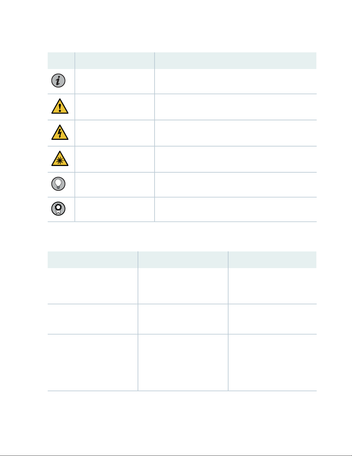
Table 1: Notice Icons
xx
DescriptionMeaningIcon
Indicates important features or instructions.Informational note
Caution
Indicates a situation that might result in loss of data or hardware
damage.
Alerts you to the risk of personal injury or death.Warning
Alerts you to the risk of personal injury from a laser.Laser warning
Indicates helpful information.Tip
Alerts you to a recommended use or implementation.Best practice
Table 2 on page xx defines the text and syntax conventions used in this guide.
Table 2: Text and Syntax Conventions
ExamplesDescriptionConvention
Fixed-width text like this
Italic text like this
Represents text that you type.Bold text like this
Represents output that appears on
the terminal screen.
Introduces or emphasizes important
•
new terms.
Identifies guide names.
•
Identifies RFC and Internet draft
•
titles.
To enter configuration mode, type
the configure command:
user@host> configure
user@host> show chassis alarms
No alarms currently active
A policy term is a named structure
•
that defines match conditions and
actions.
Junos OS CLI User Guide
•
RFC 1997, BGP Communities
•
Attribute
Page 21

Table 2: Text and Syntax Conventions (continued)
xxi
ExamplesDescriptionConvention
Italic text like this
Text like this
< > (angle brackets)
| (pipe symbol)
Represents variables (options for
which you substitute a value) in
commands or configuration
statements.
Represents names of configuration
statements, commands, files, and
directories; configuration hierarchy
levels; or labels on routing platform
components.
variables.
Indicates a choice between the
mutually exclusive keywords or
variables on either side of the symbol.
The set of choices is often enclosed
in parentheses for clarity.
Configure the machine’s domain
name:
[edit]
root@# set system domain-name
domain-name
To configure a stub area, include
•
the stub statement at the [edit
protocols ospf area area-id]
hierarchy level.
The console port is labeled
•
CONSOLE.
stub <default-metric metric>;Encloses optional keywords or
broadcast | multicast
(string1 | string2 | string3)
# (pound sign)
[ ] (square brackets)
Indention and braces ( { } )
; (semicolon)
GUI Conventions
Indicates a comment specified on the
same line as the configuration
statement to which it applies.
Encloses a variable for which you can
substitute one or more values.
Identifies a level in the configuration
hierarchy.
Identifies a leaf statement at a
configuration hierarchy level.
rsvp { # Required for dynamic MPLS
only
community name members [
community-ids ]
[edit]
routing-options {
static {
route default {
nexthop address;
retain;
}
}
}
Page 22

Table 2: Text and Syntax Conventions (continued)
xxii
ExamplesDescriptionConvention
Bold text like this
> (bold right angle bracket)
Represents graphical user interface
(GUI) items you click or select.
Separates levels in a hierarchy of
menu selections.
In the Logical Interfaces box, select
•
All Interfaces.
To cancel the configuration, click
•
Cancel.
In the configuration editor hierarchy,
select Protocols>Ospf.
Documentation Feedback
We encourage you to provide feedback so that we can improve our documentation. You can use either
of the following methods:
Online feedback system—Click TechLibrary Feedback, on the lower right of any page on the Juniper
•
Networks TechLibrary site, and do one of the following:
Click the thumbs-up icon if the information on the page was helpful to you.
•
Click the thumbs-down icon if the information on the page was not helpful to you or if you have
•
suggestions for improvement, and use the pop-up form to provide feedback.
E-mail—Send your comments to techpubs-comments@juniper.net. Include the document or topic name,
•
URL or page number, and software version (if applicable).
Requesting Technical Support
Technical product support is available through the Juniper Networks Technical Assistance Center (JTAC).
If you are a customer with an active Juniper Care or Partner Support Services support contract, or are
Page 23

covered under warranty, and need post-sales technical support, you can access our tools and resources
online or open a case with JTAC.
JTAC policies—For a complete understanding of our JTAC procedures and policies, review the JTAC User
•
Guide located at https://www.juniper.net/us/en/local/pdf/resource-guides/7100059-en.pdf.
Product warranties—For product warranty information, visit https://www.juniper.net/support/warranty/.
•
JTAC hours of operation—The JTAC centers have resources available 24 hours a day, 7 days a week,
•
365 days a year.
Self-Help Online Tools and Resources
For quick and easy problem resolution, Juniper Networks has designed an online self-service portal called
the Customer Support Center (CSC) that provides you with the following features:
Find CSC offerings: https://www.juniper.net/customers/support/
•
Search for known bugs: https://prsearch.juniper.net/
•
xxiii
Find product documentation: https://www.juniper.net/documentation/
•
Find solutions and answer questions using our Knowledge Base: https://kb.juniper.net/
•
Download the latest versions of software and review release notes:
•
https://www.juniper.net/customers/csc/software/
Search technical bulletins for relevant hardware and software notifications:
•
https://kb.juniper.net/InfoCenter/
Join and participate in the Juniper Networks Community Forum:
•
https://www.juniper.net/company/communities/
Create a service request online: https://myjuniper.juniper.net
•
To verify service entitlement by product serial number, use our Serial Number Entitlement (SNE) Tool:
https://entitlementsearch.juniper.net/entitlementsearch/
Creating a Service Request with JTAC
You can create a service request with JTAC on the Web or by telephone.
Visit https://myjuniper.juniper.net.
•
Call 1-888-314-JTAC (1-888-314-5822 toll-free in the USA, Canada, and Mexico).
•
For international or direct-dial options in countries without toll-free numbers, see
https://support.juniper.net/support/requesting-support/.
Page 24

1
CHAPTER
Overview
MX480 Router Description | 25
MX480 Chassis | 28
MX480 Cooling System | 41
MX480 Power System Description | 43
MX480 AC Power System | 44
MX480 DC Power System | 54
MX480 Host Subsystem | 61
MX480 Interface Modules—DPCs | 106
MX480 Interface Modules—FPCs and PICs | 116
MX480 Interface Modules—MPCs and MICs | 124
Services Processing Card—MX-SPC3 Services Card | 162
MX-Series Switch Control Board (SCB) Description | 168
Page 25
MX480 Router Description
IN THIS SECTION
Benefits of the MX480 Router | 25
MX480 Hardware Overview | 26
The MX480 5G Universal Routing Platform is an Ethernet-optimized edge router that provides both
switching and carrier-class Ethernet routing. The MX480 router enables a wide range of business and
residential applications and services, including high-speed transport and VPN services, next-generation
broadband multiplay services, high-speed Internet and data center internetworking.
25
Benefits of the MX480 Router
System Capacity—MX480 provides 9 Tbps of system capacity for a wide range of cloud, campus,
•
enterprise, data center, service provider, cable, and mobile service core applications.
Always-on Infrastructure Base—MX Series routers ensure network and service availability with a broad
•
set of multilayered physical, logical, and protocol-level resiliency aspects. Junos OS Virtual Chassis
technology on MX Series routers supports chassis-level redundancy and enables you to manage two
routers as a single element. Multichassis link aggregation group (MC-LAG) implementation supports
stateful chassis, card, and port redundancy.
Application-Aware Networking—On MX Series routers you can use deep packet inspection to detect
•
applications, and by using the user-defined policies, you can determine traffic treatment for each
application. This feature enables highly customized and differentiated services at scale.
Programmable Chipset—The chipset implemented in the MX Series routers has a programmable
•
forwarding data structure that allows fast microcode changes in the hardware itself, and a programmable
lookup engine that allows inline service processing. the chip’s programmable QoS engine supports coarse
and fine-grained queuing to address the requirements of core, edge, and aggregation use cases.
Junos Continuity and Unified In-Service Software Upgrade (Unified ISSU)—With the Junos continuity
•
plug-in package, you can perform a smooth upgrade when new hardware is installed in your MX Series
router.
Unified in-service software upgrade (unified ISSU) enables software upgrades and changes without
disrupting network traffic.
Page 26

Junos Telemetry Interface—Using the Junos telemetry interface data, you can stream component-level
•
data to monitor, analyze, and enhance the performance of the network. Analytics derived from this
streaming telemetry can identify current and trending congestion, resource utilization, traffic volume,
and buffer occupancy.
Integrated Hardware-Based Timing—You do not need to use external clocks because MX Series routers
•
support highly scalable and reliable hardware-based timing, including Synchronous Ethernet for frequency,
and the Precision Time Protocol (PTP) for frequency and phase synchronization. Synchronous Ethernet
and PTP can be combined in a hybrid mode to achieve a high level of frequency (10 ppb) and phase (<1.5
uS) accuracy.
MX480 Hardware Overview
The MX480 chassis provides redundancy and resiliency. The hardware system is fully redundant, including
power supplies, Routing Engines, and Switch Control Boards (SCBs).
26
The MX480 router is eight rack units (U) tall. Five routers can be stacked in a single floor-to-ceiling rack,
for increased port density per unit of floor space. The router provides eight slots that can be populated
with up to six Dense Port Concentrators (DPCs) or Modular Port Concentrators (MPCs), three Flexible PIC
Concentrators (FPCs), and two SCBs. Each FPC holds up to two PICs and each MPC holds up to two
Modular Interface Cards (MICs).
Fully populated, the MX480 router provides an aggregate switch fabric capacity of up to 5.76 Tbps and
line-rate throughput for up to 240 10-Gigabit Ethernet ports, or 24 100-Gigabit Ethernet, or 72 40-Gigabit
Ethernet ports.
Table 3 on page 26 lists the MX480 router capacity.
Table 3: MX480 Router Capacity
CapacityDescription
5.76 Tbps half duplexSystem capacity
480 GbpsSwitch fabric capacity per slot
6MPCs and DPCs per chassis
6Chassis per rack
Each DPC includes either two or four Packet Forwarding Engines. Each Packet Forwarding Engine enables
a throughput of 10 Gbps. Many types of DPCs are available. For a list of the DPCs supported, see the MX
Series Interface Module Reference.
Page 27

The MX480 supports up to 3 FPCs containing up to 6 PICs or up to 6 MPCs containing up to 12 MICs.
For a list of the supported line cards, see the MX Series Interface Module Reference.
Four SCBs are available for the MX480 routers—SCB, SCBE, SCBE2, and SCBE3.
Table 4 on page 27 compares the fabric bandwidth capacities of SCBs per MX-series router.
Table 4: Switch Control Board Capacities for MX Series 5G Universal Routing Platforms (Full-Duplex)
27
Enhanced MX Switch
Control Board (model
SCBE3-MX)
Enhanced MX Switch
Control Board
(SCBE2-MX)
Enhanced MX Switch
Control Board
(SCBE-MX)
Switch Control Board
(SCB-MX)
fabric configuration with
MPC10E line cards); 1 Tbps
(redundant fabric configuration
with MPC10E line cards)
(non-redundant fabric
configuration); 340 Gbps
(redundant fabric configuration)
(non-redundant fabric
configuration); 160 Gbps
(redundant fabric configuration)
(non-redundant fabric
configuration); 120 Gbps
(redundant fabric configuration)
MX240 Fabric
BandwidthFabric Bandwidth Per SlotDescription
MX480 Fabric
Bandwidth
MX960 Fabric
Bandwidth
Up to 33 TbpsUp to 18 TbpsUp to 6 TbpsUp to 1.5 Tbps (non-redundant
Up to 10.56 TbpsUp to 5.76 TbpsUp to 1.92 TbpsUp to 480 Gbps
Up to 5.25 TbpsUp to 2.79 TbpsUp to 930 GbpsUp to 240 Gbps
Up to 2.6 TbpsUp to 1.39 TbpsUp to 465 GbpsUp to 240 Gbps
The connections between DPCs, FPCs, MPCs, and SCBs are organized in three groups:
Switch fabric—Connects the interface cards and provides for packet transport between DPCs, FPCs,
•
and MPCs.
Control plane—Gigabit Ethernet links between the combined SCBs/Routing Engines and each DPC, FPC,
•
or MPC. All board-to-board information is passed over Ethernet except for low-level status and commands.
Management signals—Provide for low-level status diagnostic support.
•
Page 28
MX480 Chassis
IN THIS SECTION
MX480 Chassis Description | 28
MX480 Component Redundancy | 30
MX480 Router Hardware and CLI Terminology Mapping | 31
MX480 Craft Interface Description | 34
Alarm Relay Contacts on the MX480 Craft Interface | 35
Alarm LEDs and Alarm Cutoff/Lamp Test Button on the MX480 Craft Interface | 35
MX480 Component LEDs on the Craft Interface | 36
MX480 Cable Management Brackets | 39
28
MX480 Chassis Description
The router chassis is a rigid sheet metal structure that houses all the other router components (see
Figure 1 on page 29, Figure 2 on page 29, and Figure 3 on page 30). The chassis measures 14.0 in. (35.6 cm)
high, 17.45 in. (44.3 cm) wide, and 24.5 in. (62.2 cm) deep (from the front to the rear of the chassis). The
chassis installs in standard 800-mm (or larger) enclosed cabinets, 19-in. equipment racks, or telco open-frame
racks. Up to five routers can be installed in one standard 48-U rack if the rack can handle their combined
weight, which can be greater than 818 lb (371.0 kg).
Page 29
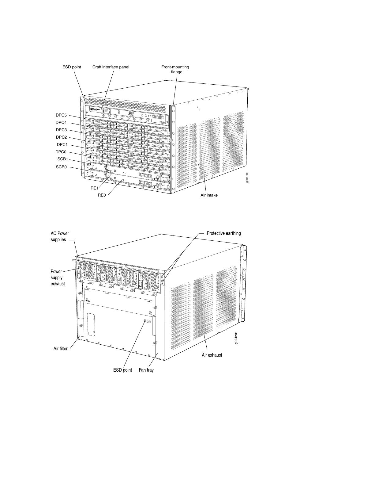
Figure 1: Front View of a Fully Configured Router Chassis
OK
MASTER
FAN
ONLINE
OFFLINE
0
1
1
0
FAIL
FAIL
PEM
FAIL
FAIL
FAIL
FAIL
FAIL
FAIL
ESD
OK
OK
OK
OK
OK
OK
OK
2
3
4
5
ACO/LT
NC
NO
C
NC
NO
C
g004200
Front-mounting
flange
SCB1
DPC5
RE1
RE0
SCB0
ESD point Craft interface panel
Air intake
DPC4
DPC3
DPC2
DPC1
DPC0
29
Figure 2: Rear View of a Fully Configured AC-Powered Router Chassis
Page 30
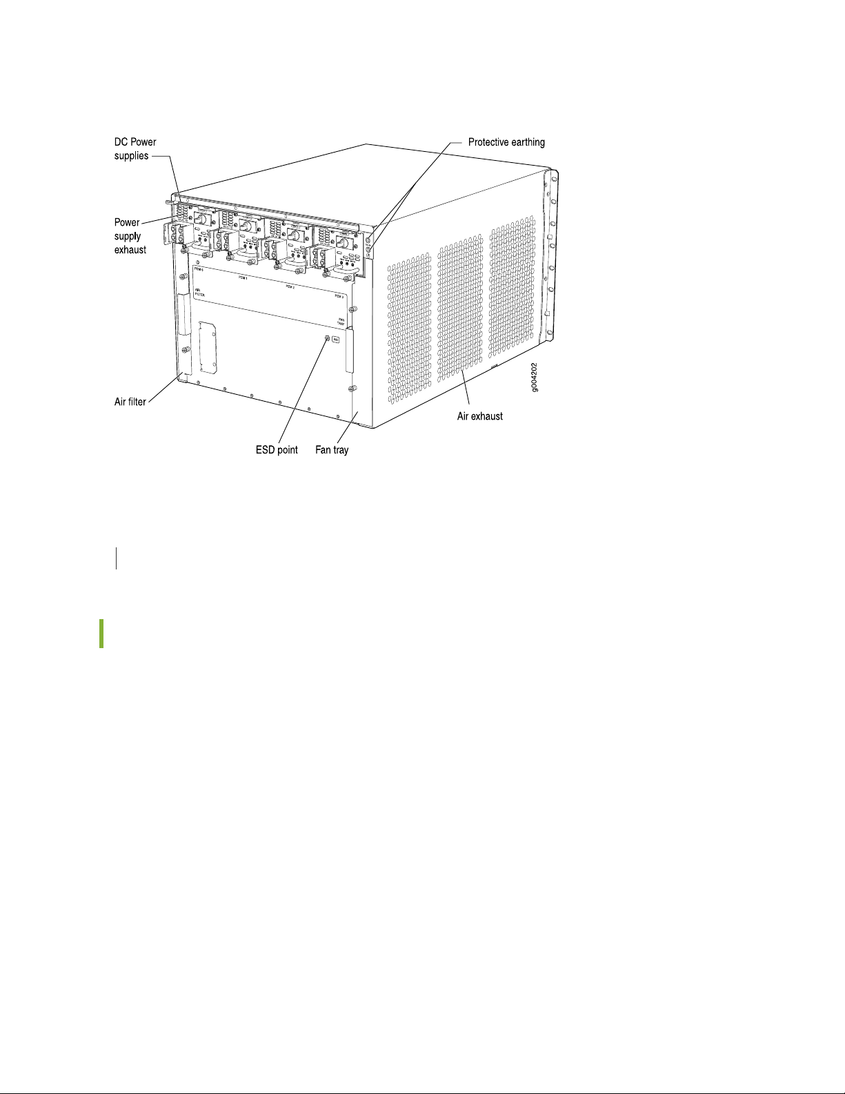
Figure 3: Rear View of a Fully Configured DC-Powered Router Chassis
30
SEE ALSO
MX480 Router Physical Specifications | 175
MX480 Component Redundancy
A fully configured router is designed so that no single point of failure can cause the entire system to fail.
Only a fully configured router provides complete redundancy. All other configurations provide partial
redundancy. The following major hardware components are redundant:
Host subsystem—The host subsystem consists of a Routing Engine functioning together with an SCB.
•
The router can have one or two host subsystems. If two host subsystems are installed, one functions as
the primary and the other functions as the backup. If the primary host subsystem (or either of its
components) fails, the backup can take over as the primary. To operate, each host subsystem requires
a Routing Engine installed directly into in an SCB.
If the Routing Engines are configured for graceful switchover, the backup Routing Engine automatically
synchronizes its configuration and state with the primary Routing Engine. Any update to the primary
Routing Engine state is replicated on the backup Routing Engine. If the backup Routing Engine assumes
primary role, packet forwarding continues through the router without interruption. For more information
about graceful switchover, see the Junos OS Administration Library.
Page 31

Power supplies—In the low-line (110 V) AC power configuration, the router contains three or four AC
•
power supplies, located horizontally at the rear of the chassis in slots PEM0 through PEM3 (left to right).
Each AC power supply provides power to all components in the router. When three power supplies are
present, they share power almost equally within a fully populated system. Four AC power supplies
provide full power redundancy. If one power supply fails or is removed, the remaining power supplies
instantly assume the entire electrical load without interruption. Three power supplies provide the
maximum configuration with full power for as long as the router is operational.
In the high-line (220 V) AC power configuration, the router contains two or four AC power supplies
located horizontally at the rear of the chassis in slots PEM0 through PEM3 (left to right). Each AC power
supply provides power to all components in the router. When two or more power supplies are present,
they share power almost equally within a fully populated system. Four AC power supplies provide full
power redundancy. If one power supply fails or is removed, the remaining power supplies instantly
assume the entire electrical load without interruption. Two power supplies provide the maximum
configuration with full power for as long as the router is operational.
In the DC configuration, two power supplies are required to supply power to a fully configured router.
One power supply supports approximately half of the components in the router, and the other power
supply supports the remaining components. The addition of two power supplies provides full power
redundancy. If one power supply fails or is removed, the remaining power supplies instantly assume the
entire electrical load without interruption. Two power supplies provide the maximum configuration with
full power for as long as the router is operational.
31
Cooling system—The cooling system has redundant components, which are controlled by the host
•
subsystem. If one of the fans fails, the host subsystem increases the speed of the remaining fans to
provide sufficient cooling for the router indefinitely.
MX480 Router Hardware and CLI Terminology Mapping
The MX480 router supports the components in Table 5 on page 31.
Table 5: MX480 Router Hardware Components and CLI Terminology
DescriptionCLI NameHardware Model NumberComponent
MX480CHAS-BP-MX480Chassis
CRAFT-MX480-SCraft Interface Panel
Front Panel
Display
“MX480 Router Physical Specifications” on
page 175
“MX480 Chassis Description” on page 28
“MX480 Craft Interface Description” on
page 34
Page 32

Table 5: MX480 Router Hardware Components and CLI Terminology (continued)
DescriptionCLI NameHardware Model NumberComponent
Cooling System
32
Host Subsystem
Routing Engine
Left Fan trayFFANTRAY-MX480Fan tray
FFANTRAY-MX480-HCHigh-capacity fan tray
See “Supported Routing Engines by Router” on
page 86.
SCBE-MX
SCBE2-MX
Enhanced
Left Fan Tray
N/AFLTR-KIT-MX480Filter kit
SCBE
SCB 2
“MX480 Cooling System Description” on
page 41
“MX480 Host Subsystem Description” on
page 61
“MX480 Routing Engine Description” on
page 63
SCB-MX DescriptionMX SCBSCB-MXSwitch Control Board
SCBE-MX DescriptionEnhanced MX
SCBE2-MX DescriptionEnhanced MX
Interface Modules
DPC
MIC
SCBE3-MX
SCB 3
See “DPCs Supported on MX240, MX480, and
MX960 Routers” on page 113 in the MX Series
Interface Module Reference.
MX-FPC2FPC
MX-FPC3
See “MICs Supported by MX Series Routers”
on page 138 in the MX Series Interface Module
Reference.
MX FPC Type
2
MX FPC Type
3
SCBE3-MX DescriptionEnhanced MX
“MX480 Dense Port Concentrator (DPC)
Description” on page 106
“MX480 Flexible PIC Concentrator (FPC)
Description” on page 116
“MX480 Modular Interface Card (MIC)
Description” on page 133
Page 33

Table 5: MX480 Router Hardware Components and CLI Terminology (continued)
DescriptionCLI NameHardware Model NumberComponent
33
MPC
PIC
Interface module blank
panel
Transceiver
Power System
See “MPCs Supported by MX Series Routers”
on page 151 in the MX Series Interface Module
Reference.
MX960 Routers” on page 122 in the MX Series
Interface Module Reference.
N/ADPC-SCB-BLANK
MIC-BLANK
XcvrSee MX Series Interface Module
Reference
PWR-MX480-ACAC power supply
AC Power
Entry Module
“MX480 Modular Port Concentrator (MPC)
Description” on page 148
“MX480 PIC Description” on page 119See “PICs Supported by MX240, MX480, and
“Installing an SFP or XFP Transceiver into
an MX480 DPC, MPC, MIC, or PIC” on
page 400
“MX480 Power System Description” on
page 43
“MX480 AC Power Supply Description” on
page 44
PWR-MX480-1200-AC
PWR-MX480-2520-AC
PWR-MX480-DCDC power supply
PWR-MX480-1600-DC
PWR-MX480-2400-DC
PS 1.2-1.7kW
100-240V AC
in
PS
1.4-2.52kW;
90-264V AC
in
DC Power
Entry Module
DC Power
Entry Module
DC 2.4kW
Power Entry
Module
“MX480 DC Power Supply Description” on
page 54
Page 34

Table 5: MX480 Router Hardware Components and CLI Terminology (continued)
DescriptionCLI NameHardware Model NumberComponent
34
N/APWR-BLANK-MX480Power supply blank
panel
SEE ALSO
MX480 DPC Port and Interface Numbering | 109
MX480 MIC Port and Interface Numbering | 134
MX480 PIC Port and Interface Numbering | 120
MX Series Router Interface Names
“MX480 Power System Description” on
page 43
MX480 Craft Interface Description
The craft interface allows you to view status and troubleshooting information at a glance and to perform
many system control functions. It is hot-insertable and hot-removable. The craft interface is located on
the front of the router above the card cage and contains LEDs for the router components, the alarm relay
contacts, and alarm cutoff button. See Figure 4 on page 34.
Figure 4: Front Panel of the Craft Interface
NOTE: At least one SCB must be installed in the router for the craft interface to obtain power.
Page 35

Alarm Relay Contacts on the MX480 Craft Interface
The craft interface has two alarm relay contacts for connecting the router to external alarm devices (see
Figure 5 on page 35). Whenever a system condition triggers either the red or yellow alarm on the craft
interface, the alarm relay contacts are also activated. The alarm relay contacts are located on the upper
right of the craft interface.
Figure 5: Alarm Relay Contacts
35
Alarm LEDs and Alarm Cutoff/Lamp Test Button on the MX480 Craft Interface
Two large alarm LEDs are located at the upper right of the craft interface. The circular red LED lights to
indicate a critical condition that can result in a system shutdown. The triangular yellow LED lights to indicate
a less severe condition that requires monitoring or maintenance. Both LEDs can be lit simultaneously.
A condition that causes an LED to light also activates the corresponding alarm relay contact on the craft
interface.
To deactivate red and yellow alarms, press the button labeled ACO/LT (for “alarm cutoff/lamp test”), which
is located to the right of the alarm LEDs. Deactivating an alarm turns off both LEDs and deactivates the
device attached to the corresponding alarm relay contact on the craft interface.
Table 6 on page 36 describes the alarm LEDs and alarm cutoff button in more detail.
Page 36

Table 6: Alarm LEDs and Alarm Cutoff/Lamp Test Button
DescriptionStateColorShape
36
Red
Yellow
On
steadily
On
steadily
––
Critical alarm LED—Indicates a critical condition
that can cause the router to stop functioning.
Possible causes include component removal,
failure, or overheating.
Warning alarm LED—Indicates a serious but
nonfatal error condition, such as a maintenance
alert or a significant increase in component
temperature.
Alarm cutoff/lamp test button—Deactivates red
and yellow alarms. Causes all LEDs on the craft
interface to light (for testing) when pressed and
held.
MX480 Component LEDs on the Craft Interface
IN THIS SECTION
Host Subsystem LEDs on the MX480 Craft Interface | 36
Power Supply LEDs on the MX480 Craft Interface | 37
DPC and MPC LEDs on the MX480 Craft Interface | 37
FPC LEDs on the MX480 Craft Interface | 38
SCB LEDs on the MX480 Craft Interface | 38
Fan LEDs on the MX480 Craft Interface | 39
Host Subsystem LEDs on the MX480 Craft Interface
Each host subsystem has three LEDs, located on the upper left of the craft interface, that indicate its status.
The LEDs labeled RE0 show the status of the Routing Engine in slot 0 and the SCB in slot 0. The LEDs
labeled RE1 show the status of the Routing Engine and SCB in slot 1. Table 7 on page 37 describes the
functions of the host subsystem LEDs on the craft interface.
Page 37

Table 7: Host Subsystem LEDs on the Craft Interface
DescriptionStateColorLabel
37
GreenMASTER
steadily
GreenONLINE
steadily
RedOFFLINE
steadily
Host is functioning as the primary.On
Host is online and is functioning normally.On
Host is installed but the Routing Engine is offline.On
Host is not installed.Off–
Power Supply LEDs on the MX480 Craft Interface
Each power supply has two LEDs on the craft interface that indicate its status. The LEDs, labeled 0 through
3, are located on the upper left of the craft interface next to the PEM label. Table 8 on page 37 describes
the functions of the power supply LEDs on the craft interface.
Table 8: Power Supply LEDs on the Craft Interface
DescriptionStateColorLabel
GreenPEM
steadily
Red
steadily
Power supply is functioning normally.On
Power supply has failed or power input has failed.On
DPC and MPC LEDs on the MX480 Craft Interface
Each DPC or MPC has LEDs on the craft interface that indicate its status. The LEDs, labeled 0 through 5,
are located along the bottom of the craft interface. Table 9 on page 38 describes the functions of the
LEDs.
Page 38

Table 9: DPC and MPC LEDs on the Craft Interface
DescriptionStateColorLabel
38
GreenOK
steadily
RedFAIL
steadily
Card is functioning normally.On
Card is transitioning online or offline.Blinking
The slot is not online.Off–
Card has failed.On
FPC LEDs on the MX480 Craft Interface
An FPC takes up two DPC slots when installed in an MX Series router. The LEDs, labeled 0 through 5, are
located along the bottom of the craft interface. The LED corresponds to the lowest DPC slot number in
which the FPC is installed. Table 10 on page 38 describes the functions of the FPC LEDs.
Table 10: FPC LEDs on the Craft Interface
DescriptionStateColorLabel
GreenOK
steadily
RedFAIL
steadily
FPC is functioning normally.On
FPC is transitioning online or offline.Blinking
The slot is not online.Off–
FPC has failed.On
SCB LEDs on the MX480 Craft Interface
Each SCB has two LEDs on the craft interface that indicates its status. The SCB LEDs, labeled 0 and 1, are
located along the bottom of the craft interface. Table 11 on page 39 describes the functions of the SCB
LEDs.
Page 39

Table 11: SCB LEDs on the Craft Interface
DescriptionStateColorLabel
39
GreenOK
RedFAIL
On
steadily
steadily
SCB: Fabric and control board functioning
normally.
SCB is transitioning online or offline.Blinking
The slot is not online.Off–
SCB has failed.On
Fan LEDs on the MX480 Craft Interface
The fan LEDs are located on the top left of the craft interface. Table 12 on page 39 describes the functions
of the fan LEDs.
Table 12: Fan LEDs on the Craft Interface
DescriptionStateColorLabel
GreenFAN
steadily
Fan is functioning normally.On
Red
steadily
Fan has failed.On
MX480 Cable Management Brackets
The cable management brackets (see Figure 6 on page 40 and Figure 7 on page 40) consist of plastic
dividers located on the left and right sides of each DPC, FPC, or MPC slot, and SCB slot. The cable
management brackets allow you to route the cables outside the router and away from the DPCs, MPCs,
MICs, PICs, and SCBs.
Page 40

Figure 6: Cable Management Brackets
Figure 7: Cable Management Brackets Installed on the Router
40
SEE ALSO
Maintaining Cables That Connect to MX480 DPCs, MPCs, MICs, or PICs | 377
Replacing the MX480 Cable Management Brackets | 279
Page 41

MX480 Cooling System
IN THIS SECTION
MX480 Cooling System Description | 41
MX480 Fan LED | 43
MX480 Cooling System Description
The cooling system consists of the following components:
Fan tray
•
41
Air filter
•
The cooling system components work together to keep all router components within the acceptable
temperature range (see Figure 8 on page 41, Figure 9 on page 42, and Figure 10 on page 42). The router
has one fan tray and one air filter that install vertically in the rear of the router. The fan tray contains six
fans. The MX Series high-capacity fan trays satisfy cooling requirements for high-density DPCs and MPCs,
and must be upgraded for proper cooling.
The air intake to cool the chassis is located on the side of the chassis next to the air filter. Air is pulled
through the chassis toward the fan tray, where it is exhausted out the side of the system. The air intake
to cool the power supplies is located in the front of the router above the craft interface. The exhaust for
the power supplies is located on the rear bulkhead power supplies.
Figure 8: Airflow Through the Chassis
Page 42

The host subsystem monitors the temperature of the router components. When the router is operating
normally, the fans function at lower than full speed. If a fan fails or the ambient temperature rises above
a threshold, the speed of the remaining fans is automatically adjusted to keep the temperature within the
acceptable range. If the ambient maximum temperature specification is exceeded and the system cannot
be adequately cooled, the Routing Engine shuts down the system by disabling output power from each
power supply.
Figure 9: Fan Tray
42
Figure 10: Air Filter
Page 43

MX480 Fan LED
Each fan has an LED that displays its status. The fan LEDs are located on the top left of the craft interface.
For more information, see “Fan LED on the MX480 Craft Interface” on page 39.
SEE ALSO
Maintaining the MX480 Fan Tray | 284
Troubleshooting the MX480 Cooling System | 428
MX480 Power System Description
43
The MX480 router uses either AC or DC power supplies. The MX480 router is configurable with two,
three, or four AC power supplies or two or four DC power supplies. The power supplies connect to the
midplane, which distributes the different output voltages produced by the power supplies to the router
components, depending on their voltage requirements. Each power supply is cooled by its own internal
cooling system.
CAUTION: The router cannot be powered from AC and DC power supplies
simultaneously.
Redundant power supplies are hot-removable and hot-insertable, as described in “MX480 Field-Replaceable
Units (FRUs)” on page 273.
CAUTION: When you remove a power supply from a router that uses a nonredundant
power supply configuration, the router might shut down depending on your
configuration.
NOTE:
Enhanced AC and DC power supplies are an upgrade for the MX480 router, and satisfy power
requirements for higher-density DPCs. When upgrading to enhanced power supplies, always
upgrade power supplies in adjacent slots.
Page 44

NOTE: Routers configured with DC power supplies are shipped with a blank panel installed over
the power distribution modules. Routers configured with AC power supplies have no blank panel.
RELATED DOCUMENTATION
Connecting Power to an AC-Powered MX480 Router with Normal-Capacity Power Supplies | 249
Connecting Power to a DC-Powered MX480 Router with Normal Capacity Power Supplies | 252
Replacing an MX480 AC Power Supply | 385
MX480 Chassis Grounding Specifications | 179
MX480 Router Grounding Cable Lug Specifications
44
MX480 AC Power System
IN THIS SECTION
MX480 AC Power Supply Description | 44
MX480 AC Power Supply LEDs | 46
AC Electrical Specifications for the MX480 Router | 47
AC Power Circuit Breaker Requirements for the MX480 Router | 49
AC Power Cord Specifications for the MX480 Router | 49
Outstanding Issues with the MX480 Router | 52
Errata with the MX480 Router Documentation | 53
MX480 AC Power Supply Description
Each AC power supply weighs approximately 5.0 lb (2.3 kg) and consists of one AC appliance inlet, an AC
input switch, a fan, and LEDs to monitor the status of the power supply. Figure 11 on page 45 shows the
power supply. For existing power supplies, each inlet requires a dedicated AC power feed and a dedicated
15 A (250 VAC) circuit breaker.
Page 45

For high-capacity power supplies, each inlet requires a dedicated AC power feed and a dedicated 16.0 A
AC OK
DC OK
PS
FAIL
@ 100 VAC or 16.0 A @ 200 VAC circuit breaker, or as required by local code.
The maximum inrush current for a high-capacity AC power supply is 49A at 264VAC.
Figure 11: AC Power Supply
45
Figure 12: High-Capacity AC Power Supply
WARNING: The router is pluggable type A equipment installed in a restricted-access
location. It has a separate protective earthing terminal (sized for UNC 1/4-20 ground
lugs) provided on the chassis in addition to the grounding pin of the power supply cord.
This separate protective earthing terminal must be permanently connected to earth.
Page 46

AC Power Supply Configurations
The MX480 high-capacity and normal-capacity power supplies each support either of the following AC
power configurations:
In the low-line (110 V) AC power configuration, the MX480 router contains three or four AC power
•
supplies (see Figure 11 on page 45), located horizontally at the rear of the chassis in slots PEM0 through
PEM3 (left to right). Each AC power supply provides power to all components in the router. When three
power supplies are present, they share power almost equally within a fully populated system. Four AC
power supplies provide full power redundancy. If one power supply fails or is removed, the remaining
power supplies assume the entire electrical load without interruption. Three power supplies provide the
maximum configuration with full power for as long as the router is operational. The low-line configuration
requires three power supplies and the fourth power supply provides redundancy. With high-capacity
power supplies, you must have a minimum of three power supplies installed in the router.
In the high-line (220 V) AC power configuration, the MX480 router contains two or four AC power
•
supplies (see Figure 11 on page 45), located horizontally at the rear of the chassis in slots PEM0 through
PEM3 (left to right). In a high-line AC power configuration, each AC power supply provides power to all
components in the router. When two or more power supplies are present, they share power almost
equally within a fully populated system. Four AC power supplies provide full power redundancy. If one
power supply fails or is removed, the remaining power supplies assume the entire electrical load without
interruption. Two power supplies provide the maximum configuration with full power for as long as the
router is operational. In the two-PEM high-line configuration, slots PEM0 and PEM1 or PEM2 and PEM3
are used. The high-line configuration requires two power supplies, with the third and fourth providing
redundancy. With high-capacity power supplies, you must have a minimum of two power supplies
installed in the router.
46
MX480 AC Power Supply LEDs
Each AC power supply faceplate contains three LEDs that indicate the status of the power supply (see
Table 13 on page 47). The power supply status is also reflected in two LEDs on the craft interface. In
addition, a power supply failure triggers the red alarm LED on the craft interface.
Page 47

Table 13: AC Power Supply LEDs
47
DescriptionStateColorLabel
AC power input voltage is below 78 VAC.OffYellowAC OK
AC power input voltage is within 78–264 VAC.OnGreen
OffGreenDC OK
On
On
DC power outputs generated by the power supply are not within the normal
operating ranges.
DC power outputs generated by the power supply are within the normal
operating ranges.
Power supply is functioning normally.OffRedPS FAIL
Power supply is not functioning normally and its output voltage is out of
regulation limits. Check AC OK and DC OK LEDs for more information.
AC Electrical Specifications for the MX480 Router
Table 14 on page 47 lists the AC power supply electrical specifications; Table 15 on page 48 lists the AC
power system specifications.
Table 14: AC Power Supply Electrical Specifications
SpecificationItem
Normal-Capacity Power Supplies
Maximum output power
1027 W (low line)
1590 W (high line)
Operating range: 100 – 240 VAC (nominal)AC input voltage
50 to 60 Hz (nominal)AC input line frequency
11.0 A @ 200 VAC or 14.5 A @ 110 VAC maximumAC input current rating
Page 48

Table 14: AC Power Supply Electrical Specifications (continued)
SpecificationItem
85% (low line and high line)Efficiency
NOTE: This value is at
full load and nominal
voltage.
High-Capacity Power Supplies
48
Maximum output power
AC input current rating
Efficiency
NOTE: This value is at
full load and nominal
voltage.
1167 W (low line)
2050 W (high line)
Operating range: 100 – 240 VAC (nominal)AC input voltage
50 to 60 Hz (nominal)AC input line frequency
16 A @ 110 VAC maximum
15.1 A @ 200 VAC maximum
84% (low line)
89% (high line)
Table 15: AC Power System Specifications
Normal
Capacity–Low
LineItem
Normal-Capacity–High
Line
High-Capacity–Low
Line
High-Capacity–High
Line
per power supply
per system
SEE ALSO
2+23+12+23+1Redundancy
2050 W1167 W3200 W1027 WOutput power (maximum)
4100 W3501 W3200 W3081 WOutput power (maximum)
Page 49

Calculating Power Requirements for MX480 Routers | 196
AC Power Circuit Breaker Requirements for the MX480 Router
Each AC power supply has a single AC appliance inlet located on the power supply that requires a dedicated
AC power feed. We recommend that you use a customer site circuit breaker rated for 15 A (250 VAC)
minimum for each AC power supply, or as required by local code. Doing so enables you to operate the
router in any configuration without upgrading the power infrastructure.
AC Power Cord Specifications for the MX480 Router
Each AC power supply has a single AC appliance inlet located on the power supply that requires a dedicated
AC power feed. Most sites distribute power through a main conduit that leads to frame-mounted power
distribution panels, one of which can be located at the top of the rack that houses the router. An AC power
cord connects each power supply to the power distribution panel.
49
You can order detachable AC power cords, each approximately 8 ft (2.5 m) long that supply AC power to
the router. The C19 appliance coupler end of the cord inserts into the AC appliance inlet coupler, type
C20 (right angle) as described by International Electrotechnical Commission (IEC) standard 60320. The
plug end of the power cord fits into the power source receptacle that is standard for your geographical
location.
Table 16 on page 49 provides specifications and Figure 13 on page 50 depicts the plug on the AC power
cord provided for each country or region.
Table 16: AC Power Cord Specifications
Electrical
Plug Type
SAA/3/15240 VAC, 50 Hz ACCBL-M-PWR-RA-AUAustralia
CH2-16P220 VAC, 50 Hz ACCBL-M-PWR-RA-CHChina
CEE 7/7220 or 230 VAC, 50
CEI 23-16/VII230 VAC, 50 Hz ACCBL-M-PWR-RA-ITItaly
Switzerland, and United Kingdom)
SpecificationModel NumberCountry
CBL-M-PWR-RA-EUEurope (except Denmark, Italy,
Hz AC
Page 50

Table 16: AC Power Cord Specifications (continued)
Electrical
SpecificationModel NumberCountry
50
Plug Type
Figure 13: AC Plug Types
CBL-PWR-RA-JP15Japan
CBL-M-PWR-RA-JP
JIS 8303125 VAC, 50 or 60 Hz
AC
NEMA L6-20P220 VAC, 50 or 60 Hz
AC
NEMA 5-15P125 VAC, 60 Hz ACCBL-PWR-RA-US15North America
NEMA L5-15P125 VAC, 60 Hz ACCBL-PWR-RA-TWLK-US15
NEMA 6-20250 VAC, 60 Hz ACCBL-M-PWR-RA-US
NEMA L6-20P250 VAC, 60 Hz ACCBL-M-PWR-RA-TWLK-US
BS89/13240 VAC, 50 Hz ACCBL-M-PWR-RA-UKUnited Kingdom
Page 51

WARNING: The AC power cord for the router is intended for use with the router only
and not for any other use.
WARNING:
Translation from Japanese: The attached power cable is only for this product. Do not
use the cable for another product.
51
NOTE: In North America, AC power cords must not exceed 4.5 m (approximately 14.75 ft) in
length, to comply with National Electrical Code (NEC) Sections 400-8 (NFPA 75, 5-2.2) and
210-52, and Canadian Electrical Code (CEC) Section 4-010(3). You can order AC power cords
that are in compliance.
WARNING: The router is pluggable type A equipment installed in a restricted-access
location. It has a separate protective earthing terminal (sized for UNC 1/4-20 ground
lugs) provided on the chassis in addition to the grounding pin of the power supply cord.
This separate protective earthing terminal must be permanently connected to earth.
CAUTION: Power cords and cables must not block access to device components or
drape where people could trip on them.
SEE ALSO
Connecting Power to an AC-Powered MX480 Router with Normal-Capacity Power Supplies | 249
Replacing an MX480 AC Power Supply Cord | 388
Page 52

Calculating Power Requirements for MX480 Routers | 196
Outstanding Issues with the MX480 Router
This topic lists outstanding hardware issues with the MX480 router. For information about software issues,
see the Junos OS Release Notes.
In Junos OS Release 10.0R2, if a third AC supply is inserted in an empty slot (even though the power
•
supply is turned off and the AC cord is not plugged in), the operational power supplies’ output voltage
reading in the Junos OS can show an inaccurate number (60-61V instead of 57V) under some conditions,
such as when the load is nearly 100% and the operating temperature exceeds 40C.
There is an input mode switch on each MX480 DC high capacity power supply, covered by a small plate.
•
The input mode switch tells the system what capacity feed is connected (60A or 70A), which in turn is
used for power inventory management When the input mode switch is set to '0' (zero): expect 60A
feeds, with a voltage range of -39V to -72VDC. When the input mode switch is set to '1' (one), expect
70A feeds or 60A feed with minimum voltage range 42V and up. The default setting is 1
52
In Junos OS Releases 10.0R3, 10.1R2, and 10.2R1, the MX480 DC high capacity power supply input
mode switch is not operating as expected, though this has no effect on the power supply operations, it
will generate alarms incorrectly. [PR532230]
NOTE:
All supplies should have the same feed setting.
•
Correct usage of the feed setting is required for all supplies in order to get the desired power
•
inventory management.
Juniper Networks strongly recommends that you install Junos OS Release 8.4R2 or later before deploying
•
the MX480 router into service.
The XFP cages and optics on the MX480 router are industry standard parts that have limited tactile
•
feedback for insertion of optics and fiber. You need to insert the optics and fiber firmly until the latch
is securely in place. [PR/98055]
Do not mix AC and DC power supplies on an MX480 router. Mixing of AC supplies and DC supplies may
•
damage your chassis. [PR/233340]
Page 53

Errata with the MX480 Router Documentation
This topic lists outstanding documentation issues:
The shut-down voltage and start-up voltages as stated in the following note in the MX480 hardware
•
guides and MX480 Quick Start are not correct under all circumstances: [PR/273771]
NOTE: If the input voltage from the DC power source drops below –36.5 to –38.5 VDC, the
router automatically shuts down. During automatic shutdown, the circuit remains active. When
the input voltage returns to –40.0 to –41.0 VDC, the router automatically starts up again and
the system returns to normal operation within 30 minutes. No operator intervention is required.
For the cooling system to function properly, the airflow around the chassis must be unrestricted. Allow
•
at least 8 in. (20.3 cm) of clearance between side-cooled routers. Allow 5.5 in. (14 cm) between the side
of the chassis and any non-heat-producing surface such as a wall. [PR/258887]
53
When installing the router without a mechanical lift, remove and reinstall components from the chassis,
•
first from the rear and then from the front. Components should be removed and reinstalled in the
following order: power supplies, fan tray, SCBs, and DPCs.[PR/265034]
Replace the air filter, located at the left rear of the router, every 6 months for optimum cooling system
•
performance.
Two threaded inserts (PEM nuts) are provided on the upper rear of the chassis for connecting the router
•
to earth ground. The grounding points fit UNC 1/4–20 screws (American).
The mounting shelf should be installed on the back of the rail as described in the MX480 Universal Routing
•
Platform Hardware Guide.
After installing a DC power cable or AC power cord, route the power cable or power cord along the
•
cable restraint towards the left or right corner of the chassis. If needed, thread plastic cable ties, which
you must provide, through the openings on the cable restraint to hold the power cord or cables in place.
Table 7 on page 37 describes the functions of the host subsystem OFFLINE LED.
•
Table 17: Host Subsystem OFFLINE LED
DescriptionStateColorLabel
RedOFFLINE
steadily
Host is installed but the Routing Engine is offline.On
Host is not installed.Off
Page 54

MX480 DC Power System
IN THIS SECTION
MX480 DC Power Supply Description | 54
MX480 DC Power Supply LEDs | 56
DC Power Supply Electrical Specifications for the MX480 Router | 56
DC Power Circuit Breaker Requirements for the MX480 Router | 58
DC Power Source Cabling for the MX480 Router | 58
DC Power Cable Specifications for the MX480 Router | 60
54
MX480 DC Power Supply Description
Each DC power supply weighs approximately 3.8 lb (1.7 kg) and consists of one DC input (–48 VDC and
return), one 40 A (–48 VDC) circuit breaker, a fan, and LEDs to monitor the status of the power supply.
Figure 14 on page 54 shows the power supply. Each DC power supply has a single DC input (–48 VDC
and return) that requires a dedicated circuit breaker.
For high capacity power supplies, we recommend that you provision 60 A or 70 A per feed, depending on
the selected DIP switch setting.
Figure 14: DC Power Supply
Page 55

Figure 15: High-Capacity DC Power Supply
g004725
DC Power Supply Configurations
In the DC power configuration, the MX480 router contains either two or four DC power supplies (see
Figure 14 on page 54) located at the rear of the chassis in slots PEM0 through PEM3 (left to right). You
can upgrade your DC power system from two to four power supplies.
55
Four power supplies provide full redundancy. If a DC power supply in a redundant configuration is removed
or fails, its redundant power supply takes over without interruption. The DC power supply in PEM2 serves
as redundant to the DC power supply in slot PEM0, and the DC power supply in PEM3 serves as redundant
to the DC power supply in slot PEM1. If only two DC power supplies are installed, they must be installed
in slots PEM0 and PEM1 or in slots PEM2 and PEM3.
Table 18 on page 55 shows the components that are powered by each DC power supply slot. It applies
to existing and high-capacity power supplies.
Table 18: Power Supply Redundancy and Power Distribution
Power Supply Provides Power to the Following ComponentsDC Power Supply Slot
Fan tray, DPC slots 0 and 1, and SCB slots 0 and 1PEM0
Fan tray and DPC slots 2 through 5PEM1
Fan tray, DPC slots 0 and 1, and SCB slots 0 and 1PEM2
Fan tray and DPC slots 2 through 5PEM3
Page 56

MX480 DC Power Supply LEDs
Each DC power supply faceplate contains three LEDs that indicate the status of the power supply (see
Table 19 on page 56). The power supply status is also reflected in two LEDs on the craft interface.In
addition, a power supply failure triggers the red alarm LED on the craft interface.
NOTE: An SCB must be present for the PWR OK LED to go on.
Table 19: DC Power Supply LEDs
DescriptionStateColorLabel
56
OffGreenPWR OK
OnYellow
On
OnYellow
Power supply is not functioning normally. Check the INPUT OK LED for
more information.
Power supply is functioning normally.On
The main output voltage is out of range (lower limit: 37.5 V to 39.5 V; upper
limit: 72.5 V to 76 V).
DC power supply circuit breaker is turned off.OffGreenBRKR ON
DC power input is present and the DC power supply circuit breaker is turned
on.
DC input to the PEM is not present.OffGreenINPUT OK
DC input is present and is connected in correct polarity.On
DC input is present, but not in valid operating range or connected in reverse
polarity.
DC Power Supply Electrical Specifications for the MX480 Router
Table 20 on page 57 lists the DC power supply electrical specifications. Table 21 on page 58 lists the DC
power system specifications.
Page 57

Table 20: Power Supply Electrical Specifications
SpecificationItem
Normal-Capacity Power Supplies
1600 WMaximum output power
33.3 A @ –48 V nominal operating voltageDC input current rating
40 AMaximum Input Current
57
DC input voltage
NOTE: This value is at
full load and nominal
voltage.
Operating Range: –40.5 VDC to –72 VDC
Nominal: –48 VDC
~98%Efficiency
40 AInternal Circuit Breaker
High-Capacity Power Supplies
DC input current rating
DC input voltage
50 A @ -48 VDC normal operating
voltage
Operating Range: –40.5 VDC to –72 VDC
70 A (DIP=1)60 A (DIP=0)Maximum Input Current
2440 W2240 WMaximum output power
54.2 A @ -48 VDC normal operating
voltage
NOTE: This value is at
full load and nominal
voltage.
Nominal: –48 VDC
~98%Efficiency
Page 58

Table 21: Power System Specifications
(maximum) per
supply
(maximum) per
system
SEE ALSO
58
High-CapacityNormal-CapacityItem
2+22+2Redundancy
70 A (DIP=1)60 A (DIP=0)1600 WOutput power
2440 W2240 W
4880 W4480 W3200 WOutput power
Calculating Power Requirements for MX480 Routers | 196
DC Power Circuit Breaker Requirements for the MX480 Router
Each DC power supply has a single DC input (–48 VDC and return) that requires a dedicated circuit breaker.
If you plan to operate a maximally configured DC-powered router with normal-capacity power supplies,
we recommend that you use a dedicated customer site circuit breaker rated for 40 A (–48 VDC) minimum,
or as required by local code. If you plan to operate a maximally configured DC-powered router with
high-capacity power supplies, we recommend that you use a circuit breaker rated for 70 A (–48 VDC), or
as required by local code.
If you plan to operate a DC-powered router at less than the maximum configuration, we recommend that
you provision a circuit breaker according to respective National Electrical Code and customer site internal
standards to maintain proper level of protection for the current specified above or each DC power supply
rated for at least 125% of the continuous current that the system draws at –48 VDC.
DC Power Source Cabling for the MX480 Router
Figure 16 on page 59 shows a typical DC source cabling arrangement.
Page 59

Figure 16: Typical DC Source Cabling to the Router
The DC power supplies in PEM0 and PEM1 must be powered by dedicated power feeds derived from
feed A, and the DC power supplies in PEM2 and PEM3 must be powered by dedicated power feeds derived
from feed B. This configuration provides the commonly deployed A/B feed redundancy for the system.
CAUTION: You must ensure that power connections maintain the proper polarity.
The power source cables might be labeled (+) and (–) to indicate their polarity. There
is no standard color coding for DC power cables. The color coding used by the external
DC power source at your site determines the color coding for the leads on the power
cables that attach to the terminal studs on each power supply.
59
WARNING: For field-wiring connections, use copper conductors only.
CAUTION: Power cords and cables must not block access to device components or
drape where people could trip on them.
SEE ALSO
In Case of an Electrical Accident
Connecting Power to a DC-Powered MX480 Router with Normal Capacity Power Supplies | 252
Replacing an MX480 DC Power Supply Cable | 395
Page 60

DC Power Cable Specifications for the MX480 Router
Crimp area
6 AWG conductor
All measurements in inches
0.28
diameter
each hole
2.25
0.25 0.370.625
g001188
0.55
End view
0.08
DC Power Cable Lug Specifications—The accessory box shipped with the router includes the cable lugs
that attach to the terminal studs of each power supply (see Figure 17 on page 60).
Figure 17: DC Power Cable Lug
CAUTION: Before router installation begins, a licensed electrician must attach a cable
lug to the grounding and power cables that you supply. A cable with an incorrectly
attached lug can damage the router.
60
NOTE: The same cable lug is used for the grounding cable.
DC Power Cable Specifications—Table 22 on page 60 summarizes the specifications for the power cables,
which you must supply.
Table 22: DC Power Cable Specifications
Quantity and SpecificationCable Type
Power
Eight 6-AWG (13.3 mm2), minimum 60°C wire, or as required by the
local code
Page 61

MX480 Host Subsystem
IN THIS SECTION
MX480 Host Subsystem Description | 61
MX480 Host Subsystem LEDs | 62
MX480 Midplane Description | 62
MX480 Routing Engine Description | 63
MX480 Routing Engine LEDs | 66
RE-S-1800 Routing Engine Description | 69
RE-S-1800 Routing Engine LEDs | 71
RE-S-X6-64G Routing Engine Description | 72
RE-S-X6-64G Routing Engine LEDs | 74
61
RE-S-X6-128G Routing Engine Description | 76
Routing Engine Specifications | 79
Supported Routing Engines by Router | 86
MX480 Host Subsystem Description
The host subsystem provides the routing and system management functions of the router. You can install
one or two host subsystems on the router. Each host subsystem functions as a unit; the Routing Engine
must be installed directly into the Switch Control Board.
NOTE: We recommend that you install two host subsystems for redundant protection. If you
install only one host subsystem, we recommend that you install it in slot 0.
Each host subsystem has three LEDs that display its status. The host subsystem LEDs are located in the
middle of the craft interface.
SEE ALSO
Maintaining the MX480 Host Subsystem | 290
Page 62

Taking an MX480 Host Subsystem Offline
MX480 Host Subsystem LEDs
Each host subsystem has three LEDs that display its status. The host subsystem LEDs are located on the
upper left of the craft interface. For more information, see “Host Subsystem LEDs on the MX480 Craft
Interface” on page 36.
MX480 Midplane Description
The midplane is located toward the rear of the chassis and forms the rear of the card cage (see
Figure 18 on page 63). The line cards and SCBs install into the midplane from the front of the chassis, and
the power supplies install into the midplane from the rear of the chassis. The cooling system components
also connect to the midplane.
62
The midplane performs the following major functions:
Data path—Data packets are transferred across the midplane between the line cards through the fabric
•
ASICs on the SCBs.
Power distribution—The router power supplies connect to the midplane, which distributes power to all
•
the router components.
Signal path—The midplane provides the signal path to the line cards, SCBs, Routing Engines, and other
•
system components for monitoring and control of the system.
Page 63

Figure 18: Midplane
63
SEE ALSO
MX480 Router Description | 25
MX480 Chassis Description | 28
MX480 Dense Port Concentrator (DPC) Description | 106
MX480 Modular Port Concentrator (MPC) Description | 148
MX-Series Switch Control Board (SCB) Description | 168
MX480 Flexible PIC Concentrator (FPC) Description | 116
MX480 Power System Description | 43
MX480 Routing Engine Description
IN THIS SECTION
Routing Engine Components | 65
Routing Engine Interface Ports | 65
Routing Engine Boot Sequence | 66
Page 64

The Routing Engine is an Intel-based PC platform that runs Junos OS. Software processes that run on the
Routing Engine maintain the routing tables, manage the routing protocols used on the router, control the
router interfaces, control some chassis components, and provide the interface for system management
and user access to the router.
You can install one or two Routing Engines in the router. The Routing Engines install into the front of the
chassis in horizontal slots in the SCBs labeled 0 and 1. If two Routing Engines are installed, one functions
as the primary and the other acts as the backup. If the primary Routing Engine fails or is removed, and the
backup is configured appropriately, the backup takes over as the primary.
The Routing Engines are hot-pluggable. Each Routing Engine must be installed directly into an SCB. A USB
port on the Routing Engine accepts a USB memory card that allows you to load Junos OS.
Figure 19 on page 64 shows RE-S-1800 Routing Engine and Figure 20 on page 64 shows the RE-S-X6-64G
Routing Engine.
Figure 19: RE-S-1800 Routing Engine
64
Figure 20: RE-S-X6-64G Routing Engine Front View
6—1— ONLINE/OFFLINE ButtonExtractor clips
7—2— SSD LEDs—DISK1 and DISK2Auxiliary port (AUX)
8—3— Ports—USB1 and USB2Console port (Con)
9—4— RESET ButtonManagement port (MGMT)
10—5— SSD card slot coverLEDs—ONLINE, OK/FAIL, and MASTER
Page 65

Figure 21: RE-S-X6-64G-LT Routing Engine Front View
6—1— ONLINE/OFFLINE ButtonExtractor clips
7—2— SSD LEDs—DISK1 and DISK2Auxiliary port (AUX)
8—3— Ports—USB1 and USB2Console port (Con)
9—4— RESET ButtonManagement port (MGMT)
10—5— SSD card slot coverLEDs—ONLINE, OK/FAIL, and MASTER
Routing Engine Components
65
NOTE: For specific information about Routing Engine components (for example, the amount of
DRAM), issue the show vmhost hardware command.
Routing Engine Interface Ports
Three ports, located on the right side of the Routing Engine, connect the Routing Engine to one or more
external devices on which system administrators can issue Junos OS command-line interface (CLI) commands
to manage the router.
The ports with the indicated labels function as follows:
AUX—Connects the Routing Engine to a laptop, modem, or other auxiliary device through a serial cable
•
with an RJ-45 connector.
CONSOLE—Connects the Routing Engine to a system console through a serial cable with an RJ-45
•
connector.
ETHERNET or MGMT—Connects the Routing Engine through an Ethernet connection to a management
•
LAN (or any other device that plugs into an Ethernet connection) for out-of-band management. The port
uses an autosensing RJ-45 connector to support 10-Mbps or 100-Mbps connections. Two small LEDs
on the right of the port indicate the connection in use: The LED on the left indicates speed—green for
1000-Mbps, yellow for 100-Mbps and when the LED is dark, it indicates 10-Mbps speed. The LED on
the right indicates activity—flashing green when packets are passing through the port.
Page 66

Routing Engine Boot Sequence
The Routing Engine boots from the storage media in this order: the USB device (if present), then the
CompactFlash card, then the hard disk, then the LAN. The disk from which the router boots is called the
primary boot device, and the other disk is the alternate boot device.
NOTE: If the router boots from an alternate boot device, a yellow alarm lights the LED on the
router’s craft interface.
Booting in a RE-S-X6-64G Routing Engine follows this sequence—the USB device, SSD1, SSD2, and LAN.
SSD1 is the primary boot device. Boot sequence is tried twice for SSD1 and SSD2.
If the Routing Engines are configured for graceful switchover, the backup Routing Engine automatically
synchronizes its configuration and state with the primary Routing Engine. Any update to the primary
Routing Engine state is replicated on the backup Routing Engine. If the backup Routing Engine assumes
primary role, packet forwarding continues through the router without interruption. For more information
about graceful switchover, see the Junos OS Administration Library.
66
NOTE: If two Routing Engines are installed, they must both be the same hardware model.
SEE ALSO
MX480 Router Description | 25
MX480 Routing Engine LEDs | 66
MX480 Host Subsystem Description | 61
MX-Series Switch Control Board (SCB) Description | 168
MX480 Routing Engine LEDs
Each Routing Engine has four LEDs that indicate its status. The LEDs, labeled MASTER, HDD, ONLINE,
and FAIL, are located directly on the faceplate of the Routing Engine. Table 23 on page 67 and
Table 24 on page 68 describe the functions of the Routing Engine LEDs.
Page 67

Figure 22: RE-S-1800 Routing Engine
Table 23: RE-S-1800 Routing Engine LEDs
DescriptionStateColorLabel
67
BlueMASTER
steadily
steadily
RedFAIL
steadily
Routing Engine is the Primary.On
Indicates activity on the hard disk drive.BlinkingGreenHDD
Routing Engine is transitioning online.BlinkingGreenONLINE
Routing Engine is functioning normally.On
Routing Engine has failed.On
Page 68

Routing Engine LEDs (RE-S-X6-64G)
Figure 23: RE-S-X6-64G Routing Engine LEDs
Table 24: Routing Engine LEDs (RE-S-X6-64G)
68
4—1— DISK2 LEDONLINE LED
5—2— ONLINE/OFFLINE ButtonOK/FAIL LED
6—3— MASTER LEDDISK1 LED
DescriptionStateColorLabel
Blinking slowlyGreenONLINE
Routing Engine is in the process of booting BIOS, and the
host OS.
Routing Engine is in the process of booting Junos OS.Blinking rapidly
Routing Engine is not online or not functioning normallyOff-
Indicates presence of the disk activity.BlinkingGreenDISK1
There is no disk activity.Off-
Indicates presence of the disk activity.BlinkingGreenDISK2
There is no disk activity.Off-
Routing Engine is powering up.On steadilyGreenOK/FAIL
Routing Engine is not powering up indicating failure.On steadilyYellow
SEE ALSO
This Routing Engine is the Primary Routing Engine.On steadilyBlueMASTER
Page 69

Replacing an MX480 Routing Engine | 293
g006040
USB
port
Reset
button
Extractor
clip
Extractor
clip
Console
port
Auxiliary
port
Ethernet
port
SSD
slot 2
SSD
slot 1
RE-S-1800 Routing Engine Description
IN THIS SECTION
RE-S-1800 Routing Engine Components | 69
RE-S-1800 Routing Engine LEDs | 70
RE-S-1800 Routing Engine Boot Sequence | 71
Figure 24 on page 69 shows RE-S-1800 routing engine.
69
Figure 24: RE-S-1800 Front View
RE-S-1800 Routing Engine Components
Each Routing Engine consists of the following components:
CPU—Runs Junos OS to maintain the router's routing tables and routing protocols..
•
DRAM—Provides storage for the routing and forwarding tables and for other Routing Engine processes.
•
USB port—Provides a removable media interface through which you can install Junos OS manually. Junos
•
OS supports USB version 1.0.
CompactFlash card—Provides primary storage for software images, configuration files, and microcode.
•
The CompactFlash card is fixed and is inaccessible from outside the router.
Solid-state Drive (SSD)—Provides secondary storage for log files, memory dumps, and rebooting the
•
system if the CompactFlash card fails.
Page 70

Interface ports—The AUX, CONSOLE, and ETHERNET provide access to management devices. Each
•
Routing Engine has one 10/100/1000-Mbps Ethernet port for connecting to a management network,
and two asynchronous serial ports—one for connecting to a console and one for connecting to a modem
or other auxiliary device.
EEPROM—Stores the serial number of the Routing Engine.
•
RESET button—Reboots the Routing Engine when pressed.
•
ONLINE/OFFLINE button—Takes the Routing Engine online or offline when pressed.
•
Extractor clips—Used for inserting and extracting the Routing Engine.
•
Captive screws—Secure the Routing Engine in place.
•
NOTE: For specific information about Routing Engine components (for example, the amount of
DRAM), issue the show chassis routing-engine command.
70
RE-S-1800 Routing Engine LEDs
Each Routing Engine has four LEDs that indicate its status. The LEDs, labeled MASTER, STORAGE, ONLINE,
and OK/FAIL, are located directly on the faceplate of the Routing Engine. Table 25 on page 70 describes
the functions of the Routing Engine LEDs.
Table 25: Routing Engine LEDs
DescriptionStateColorLabel
BlueMASTER
steadily
steadily
RedOK/FAIL
steadily
Routing Engine is the Primary.On
Indicates activity on the SSD or Compact Flash.BlinkingGreenSTORAGE
Routing Engine is transitioning online.BlinkingGreenONLINE
Routing Engine is functioning normally.On
Routing Engine has failed.On
Page 71

RE-S-1800 Routing Engine Boot Sequence
The router is shipped with Junos OS preinstalled on the Routing Engine. There are three copies of software:
One copy on the CompactFlash card in the Routing Engine.
•
One copy on the hard disk in the Routing Engine.
•
One copy on a USB flash drive that can be inserted into the slot on the Routing Engine faceplate.
•
The Routing Engine boots from the storage media in this order: the USB device (if present), then the
CompactFlash card, then the Solid State Disk (SSD), then the LAN. Normally, the router boots from the
copy of the software on the CompactFlash card.
SEE ALSO
RJ-45 Connector Pinouts for MX Series Routing Engine AUX and CONSOLE Ports
RJ-45 Connector Pinouts for an MX Series Routing Engine ETHERNET Port
71
Replacing an MX960 Routing Engine
Supported Routing Engines by Router | 86
RE-S-1800 Routing Engine LEDs
Each Routing Engine has four LEDs that indicate its status. The LEDs, labeled MASTER, STORAGE, ONLINE,
and OK/FAIL, are located directly on the faceplate of the Routing Engine. Table 26 on page 71 describes
the functions of the Routing Engine LEDs.
Table 26: Routing Engine LEDs
DescriptionStateColorLabel
BlueMASTER
steadily
Routing Engine is the Primary.On
Indicates activity on the SSD or Compact Flash.BlinkingGreenSTORAGE
Routing Engine is transitioning online.BlinkingGreenONLINE
steadily
Routing Engine is functioning normally.On
Page 72

Table 26: Routing Engine LEDs (continued)
DescriptionStateColorLabel
72
RedOK/FAIL
steadily
Routing Engine has failed.On
SEE ALSO
MX240 Routing Engine Description
MX480 Routing Engine Description | 63
MX960 Routing Engine Description
RE-S-X6-64G Routing Engine Description
IN THIS SECTION
RE-S-X6-64G Routing Engine Components | 73
RE-S-X6-64G Routing Engine Boot Sequence | 74
Page 73

Figure 25 on page 73 shows the Routing Engine.
Figure 25: RE-S-X6-64G Routing Engine Front View
73
6—1— ONLINE/OFFLINE buttonExtractor clips
7—2— SSD LEDs—DISK1 and DISK2Auxiliary port (AUX)
8—3— Ports—USB1 and USB2Console port (CONSOLE)
9—4— RESET buttonManagement port (MGMT)
10—5— SSD card slot coverLEDs—ONLINE, OK/FAIL, and MASTER
RE-S-X6-64G Routing Engine Components
In routers with dual Routing Engines, both Routing Engines must be RE-S-X6-64G Routing Engines.
Each RE-S-X6-64G Routing Engine (shown in Figure 25 on page 73) consists of the following components:
CPU—Runs Junos OS to maintain the routing tables and routing protocols.
•
EEPROM—Stores the serial number of the Routing Engine.
•
DRAM—Provides storage for the routing and forwarding tables and for other Routing Engine processes.
•
One 10-Gigabit Ethernet interface between the Routing Engine and Switch Control Board.
•
Two 50-GB slim solid-state drives—SSD1 (primary) and SSD2 (secondary)—Provide storage for software
•
images, configuration files, microcode, log files, and memory dumps. The Routing Engine reboots from
SSD2 when boot from primary SSD fails.
Two USB ports (USB1 and USB2)—Provide a removable media interface through which you can install
•
Junos OS manually. The Junos OS supports USB versions 3.0, 2.0, and 1.1.
Interface ports—The AUX, CONSOLE, and MGMT provide access to management devices. Each Routing
•
Engine has one 10/100/1000-Mbps Ethernet port for connecting to a management network, and two
asynchronous serial ports—one for connecting to a console and one for connecting to a modem or other
auxiliary device.
RESET button—Reboots the Routing Engine when pressed.
•
ONLINE/OFFLINE button—Brings the Routing Engine online or takes it offline when pressed.
•
Page 74

NOTE: The ONLINE/OFFLINE button must be pressed for a minimum of 4 seconds for the
power off or power on to occur.
Extractor clips—Control the locking system that secures the Routing Engine.
•
LEDs—“RE-S-X6-64G Routing Engine LEDs” on page 74 describes the functions of these LEDs.
•
NOTE: For specific information about Routing Engine components (for example, the amount of
DRAM), issue the show vmhost hardware command.
RE-S-X6-64G Routing Engine Boot Sequence
Booting in a RE-S-X6-64G Routing Engine follows this sequence—the USB device, SSD1, SSD2, LAN. SSD1
is the primary boot device. The boot sequence is tried twice for SSD1 and SSD2.
74
SEE ALSO
Upgrading to the RE-S-X6-64G Routing Engine in a Redundant Host Subsystem | 307
Upgrading to the RE-S-X6-64G Routing Engine in a Nonredundant Host Subsystem | 313
RE-S-X6-64G Routing Engine LEDs
Each Routing Engine has five LEDs that indicate its status. The LEDs—labeled MASTER, DISK1, DISK2,
ONLINE, and OK/FAIL—are located on the faceplate of the Routing Engine. Table 27 on page 75 describes
the functions of the Routing Engine LEDs.
Page 75

Figure 26: RE-S-X6-64G Routing Engine LEDs
Table 27: RE-S-X6-64G Routing Engine LEDs
75
4—1— DISK2 LEDONLINE LED
5—2— ONLINE/OFFLINE buttonOK/FAIL LED
6—3— MASTER LEDDISK1 LED
DescriptionStateColorLabel
Green
Blinking slowlyGreenONLINE
Routing Engine is in the process of booting BIOS, and the
host OS.
Routing Engine is in the process of booting Junos OS.Blinking rapidly
Routing Engine is not online or not functioning normally.Off-
Routing Engine has booted both JunOS and host OS.On steadily
Indicates presence of disk activity.BlinkingGreenDISK1
There is no disk activity.Off-
Indicates presence of disk activity.BlinkingGreenDISK2
There is no disk activity.Off-
Routing Engine is not powering up, which indicates failure.On steadilyYellowOK/FAIL
This Routing Engine is the Primary Routing Engine.On steadilyBlueMASTER
Off-
This Routing Engine is the backup Routing Engine, if the
ONLINE LED is solid green.
Page 76

SEE ALSO
MX240 Routing Engine Description
MX960 Routing Engine Description
RE-S-X6-128G Routing Engine Description
IN THIS SECTION
RE-S-X6-128G Routing Engine Components | 76
RE-S-X6-128G Routing Engine LEDs | 77
RE-S-X6-128G Routing Engine Boot Sequence | 79
76
Figure 27 on page 76 shows the Routing Engine.
Figure 27: RE-S-X6-128G Routing Engine Front View
RE-S-X6-128G Routing Engine Components
6—1— ONLINE/OFFLINE buttonExtractor clips
7—2— SSD LEDs—DISK1 and DISK2Auxiliary port (AUX)
8—3— Ports—USB1 and USB2Console port (CONSOLE)
9—4— RESET buttonManagement port (MGMT)
10—5— SSD card slot coverLEDs—ONLINE, OK/FAIL, and MASTER
In routers with dual Routing Engines, both Routing Engines must be RE-S-X6-128G Routing Engines.
Page 77

Each RE-S-X6-128G Routing Engine (shown in Figure 27 on page 76) consists of the following components:
CPU—Runs Junos OS to maintain the routing tables and routing protocols.
•
EEPROM—Stores the serial number of the Routing Engine.
•
DRAM—Provides storage for the routing and forwarding tables and for other Routing Engine processes.
•
One 10-Gigabit Ethernet interface between the Routing Engine and Switch Control Board.
•
Two 50-GB slim solid-state drives—SSD1 (primary) and SSD2 (secondary)—Provide storage for software
•
images, configuration files, microcode, log files, and memory dumps. The Routing Engine reboots from
SSD2 when boot from primary SSD fails.
Two USB ports (USB1 and USB2)—Provide a removable media interface through which you can install
•
Junos OS manually. The Junos OS supports USB versions 3.0, 2.0, and 1.1.
Interface ports—The AUX, CONSOLE, and MGMT provide access to management devices. Each Routing
•
Engine has one 10/100/1000-Mbps Ethernet port for connecting to a management network, and two
asynchronous serial ports—one for connecting to a console and one for connecting to a modem or other
auxiliary device.
77
RESET button—Reboots the Routing Engine when pressed.
•
ONLINE/OFFLINE button—Brings the Routing Engine online or takes it offline when pressed.
•
NOTE: The ONLINE/OFFLINE button must be pressed for a minimum of 4 seconds for the
power off or power on to occur.
Extractor clips—Control the locking system that secures the Routing Engine.
•
LEDs—Table 28 on page 78 describes the functions of these LEDs.
•
NOTE: For specific information about Routing Engine components (for example, the amount of
DRAM), issue the show vmhost hardware command.
RE-S-X6-128G Routing Engine LEDs
Each Routing Engine has five LEDs that indicate its status. The LEDs—labeled MASTER, DISK1, DISK2,
ONLINE, and OK/FAIL—are located on the faceplate of the Routing Engine. Table 28 on page 78 describes
the functions of the Routing Engine LEDs.
Page 78

Figure 28: RE-S-X6-128G Routing Engine LEDs
Table 28: RE-S-X6-128G Routing Engine LEDs
78
4—1— DISK2 LEDONLINE LED
5—2— ONLINE/OFFLINE buttonOK/FAIL LED
6—3— MASTER LEDDISK1 LED
DescriptionStateColorLabel
Blinking slowlyGreenONLINE
On steadilyYellow
Routing Engine is in the process of booting BIOS, and the
host OS.
Routing Engine is in the process of booting Junos OS.Blinking rapidly
Routing Engine is not online or not functioning normally.Off-
Indicates presence of disk activity.BlinkingGreenDISK1
There is no disk activity.Off-
Indicates presence of disk activity.BlinkingGreenDISK2
There is no disk activity.Off-
Routing Engine is powering up.On steadilyGreenOK/FAIL
Routing Engine is not powering up, which indicates
failure.
This Routing Engine is the Primary Routing Engine.On steadilyBlueMASTER
Page 79

RE-S-X6-128G Routing Engine Boot Sequence
Booting in a RE-S-X6-128G Routing Engine follows this sequence—the USB device, SSD1, SSD2, LAN.
SSD1 is the primary boot device. The boot sequence is tried twice for SSD1 and SSD2.
SEE ALSO
Supported Routing Engines by Router | 86
Routing Engine Specifications | 79
Routing Engine Specifications
Table 29 on page 79 lists the current specifications for Routing Engines supported on M Series, MX Series,
and T Series routers. Table 30 on page 83 lists the hardware specifications of the Routing Engines with
VMHost support. Table 31 on page 85 lists the specifications for end-of-life Routing Engines.
79
NOTE: For a list of the routing engines that are supported on the M Series, MX Series, T Series,
and PTX routers, see “Supported Routing Engines by Router” on page 86.
NOTE: For information about PTX Series Routing Engine specifications, see Routing Engines
Supported on PTX Series Routers.
Table 29: Routing Engine Specifications
Connection
to PFEsMemoryProcessorRouting Engine
RE-400-768
RE-A-1000-2048
Celeron
Pentium
768 MB400-MHz
2048 MB1.0-GHz
Fast
Ethernet
Gigabit
Ethernet
40 GB
hard
disk
40 GB
hard
disk
CompactFlash
card
CompactFlash
card
First Junos OS
SupportMediaDisk
Switch
Control
Board
–9.01 GB
–8.11 GB
Page 80

Table 29: Routing Engine Specifications (continued)
Connection
to PFEsMemoryProcessorRouting Engine
First Junos OS
SupportMediaDisk
80
Switch
Control
Board
RE-A-2000-4096
RE-S-1300-2048
RE-S-2000-4096
Pentium
Pentium
Pentium
4096 MB2.0-GHz
2048 MB1.3-GHz
4096 MB2.0-GHz
8 GB1.8-GHzRE-C1800
Gigabit
Ethernet
Gigabit
Ethernet
Gigabit
Ethernet
Ethernet
40 GB
hard
disk
40 GB
hard
disk
40 GB
hard
disk
SSDGigabit
CompactFlash
card
CompactFlash
card
CompactFlash
card
4 GB
CompactFlash
card
T1600 router in a
routing matrix:
9.6R2
Standalone T640
or T1600
router:11.2
–8.11 GB
SCB, SCBE8.21 GB
SCB, SCBE8.21 GB
CB-T for a
standalone
router.
CB-LCC
for a router
in a routing
matrix.
16 GB1.8 Ghz
Ethernet
SSDGigabit
4 GB
CompactFlash
card
32-bit Junos OS
on a standalone
T1600 router:
11.4R2 32-bit
Junos OS on a
T1600 router in a
routing matrix:
11.4R2
64-bit Junos OS
on a standalone
T1600 router:
11.4R2 64-bit
Junos OS on a
T1600 router in a
routing matrix:
11.4R2
CB-T for a
standalone
router.
CB-LCC
for a router
in a routing
matrix.
Page 81

Table 29: Routing Engine Specifications (continued)
Connection
to PFEsMemoryProcessorRouting Engine
First Junos OS
SupportMediaDisk
81
Switch
Control
Board
16 GB2.6-GHzRE-C2600
Ethernet
1800-MHzRE-A-1800x2
1800-MHzRE-S-1800x2
1800-MHzRE-S-1800x4
8 GB or
16 GB
8 GB or
16 GB
8GB or
16 GB
4 GB1.8-GHzRE-S-MX104
4 GB1.73-GHzRE-B-1800x1-4G
Gigabit
Ethernet
Gigabit
Ethernet
Gigabit
Ethernet
Ethernet
Gigabit
Ethernet
SSDGigabit
32 GB
SSD
32 GB
SSD
32 GB
SSD
–Gigabit
64 GB
SSD
4 GB
CompactFlash
card
CompactFlash
card
CompactFlash
card
CompactFlash
card
Flash
4 GB
CompactFlash
card
router: 9.6R2
10.44 GB
10.44 GB
and 12.2R1
–TX Matrix Plus
–10.44 GB
SCB, SCBE,
SCBE2,
SCBE3
SCB, SCBE,
SCBE2,
SCBE3
–13.28 GB NAND
–12.1R2, 11.4R4,
16 GB1.8- GHzRE-MX2000-1800x4
32 GB1.8- GhzRE-S-1800X4-32G-S
32 GB1.8- GhzREMX2K-1800-32G-S
Gigabit
Ethernet
Gigabit
Ethernet
Gigabit
Ethernet
32 GB
SSD
32 GB
SSD
32 GB
SSD
Internal
CompactFlash
card
4 GB Fixed
Internal
CompactFlash
card
4GB Fixed
Internal
CompactFlash
card
12.3R4
•
13.2R1
•
12.3R4
•
13.2R1
•
SFB12.3R24 GB Fixed
SCB, SCBE,
SCBE2,
SCBE3
–
Page 82

Table 29: Routing Engine Specifications (continued)
Connection
to PFEsMemoryProcessorRouting Engine
First Junos OS
SupportMediaDisk
82
Switch
Control
Board
RE-S-X6-64G-LT
64 GB2 GhzRE-S-X6-64G,
64 GB2.3 GhzREMX2K-X8-64G
64 GB2.3 GhzREMX2K-X8-64G-LT
64 GB2.3 GhzREMX2008-X8-64G
64 GB1.6 GhzRE-S-1600x8
Gigabit
Ethernet
Gigabit
Ethernet
Gigabit
Ethernet
Gigabit
Ethernet
Gigabit
Ethernet
50-GB
SSDs
100-GB
SSDs
100-GB
SSDs
50-GB
SSDs
50-GB
SSDs
-Two
-Two
15.1F4 and 16.1
•
(RE-S-X6-64G)
17.2R1
•
(RE-S-X6-64G-LT)
16.1R2, and
16.2R1
SCBE2,
SCBE3
–15.1F5-S1,
–17.2R1-Two
–15.1F7–Two
–17.3R1–Two
64 GB2.1 GhzREMX2008-X8-64G-LT
128 GB2.3 GhzREMX2008-X8-128G
128 GB2.1 GhzRE-S-X6-128G
128 GB2.1 GhzREMX2K-X8-128G
64 GB1.6-GHzJNP10003-RE1
Gigabit
Ethernet
Gigabit
Ethernet
Gigabit
Ethernet
Gigabit
Ethernet
Gigabit
Ethernet
100-GB
SSDs
200-GB
SSDs
200-GB
SSDs
200-GB
SSDs
100 GB
SSDs
-Two
18.1R1 (SCBE2)
18.4R1 (SCBE3)
-17.2R1-Two
-18.2R1-Two
SCBE2,
SCBE3
-18.1R1-Two
-17.3R1-Two
Page 83

Table 29: Routing Engine Specifications (continued)
Connection
to PFEsMemoryProcessorRouting Engine
First Junos OS
SupportMediaDisk
83
Switch
Control
Board
64 GB1.6-GHzJNP10003-RE1-LT
32 GB2.5 GhZJNP10K-RE0
64 GB2.3 GhZJNP10K-RE1
64 GB2.3 GhZJNP10K-RE1-LT
128 GB2.3 GhZJNP10K-RE1-128
Gigabit
Ethernet
Gigabit
Ethernet
Gigabit
Ethernet
Gigabit
Ethernet
Gigabit
Ethernet
100 GB
SSDs
GB
SSDs
200 GB
SSDs
200 GB
SSDs
200 GB
SSDs
-18.1R1-Two
-17.2R1-Two 50
-18.2R1-Two
-18.3R1-Two
-18.3R1-Two
NOTE: Use shielded CAT5e cable for connecting the AUX, CONSOLE, and MGMT ports in
RE-S-X6-64G, REMX2K-X8-64G, and REMX2008-X8-64G Routing Engines.
Table 30 on page 83 lists the hardware specifications of the Routing Engines with VMHost support.
Table 30: Hardware Specifications of the RE-MX-X6, RE-MX-X8, RE-PTX-X8, RCBPTX, RE-QFX10002-60C,
and RE-PTX10002-60C Routing Engines
SpecificationsSupported on DeviceModel Number
RE-S-X6-64G
RE-S-X6-128G
MX240, MX480, and
MX960
MX240, MX480, and
MX960
6-core Haswell CPU
•
Wellsburg PCH-based Routing Engine with 64-GB DRAM and
•
two 64-GB solid-state drives (SSDs)
6-core Haswell CPU
•
Wellsburg PCH-based Routing Engine with 128-GB DRAM and
•
two 128-GB solid-state drives (SSDs)
Page 84

Table 30: Hardware Specifications of the RE-MX-X6, RE-MX-X8, RE-PTX-X8, RCBPTX, RE-QFX10002-60C,
and RE-PTX10002-60C Routing Engines (continued)
SpecificationsSupported on DeviceModel Number
84
MX2020 and MX2010REMX2K-X8-64G
PTX5000RE-PTX-X8-64G
PTX3000RCBPTX
MX10003RE-S-1600x8
MX204RE-S-1600x8
8-core Haswell CPU
•
Wellsburg PCH-based Routing Engine with 64-GB DRAM and
•
two 64-GB SSDs
8-core Haswell CPU
•
Wellsburg PCH-based Routing Engine with 64-GB DRAM and
•
two 64-GB SSDs
New Control Board CB2-PTX
•
Wellsburg PCH-based Routing Engine with 64-GB DRAM and
•
two 64-GB SSDs
Multi-core Haswell CPU
•
RCB combines the functionality of a Routing Engine, Control Board,
and Centralized Clock Generator (CCG)
High-performance 1.6-GHz Intel 8 Core X86 CPU
•
64-GB DDR4 RAM
•
100-GB SATA SSD
•
High-performance 1.6-GHz Intel 8 Core X86 CPU
•
32-GB DDR4 RAM
•
100-GB SATA SSD
•
QFX10002-60CRE-QFX10002-60C
PTX10002-60CRE-PTX10002-60C
ACX5448RE-ACX-5448
MX10008RE-X10
High-performance 1.6-GHz Intel 8 Core X86 CPU
•
32-GB DDR4 RAM
•
Two 50-GB SATA SSD
•
High-performance 1.6-GHz Intel 8 Core X86 CPU
•
32-GB DDR4 RAM
•
Two 50-GB SATA SSD
•
High-performance 1.6-GHz Intel 8 Core X86 CPU
•
32-GB two DIMM DRAM
•
Two 100-GB SATA SSD
•
High-performance 1.6-GHz Intel 10 Core X86 CPU
•
64-GB DDR4 RAM
•
Two 200-GB SATA SSD
•
Page 85

Table 31: End-of-Life Routing Engine Specifications
85
Routing
Engine
RE-333-256
RE-333-768
RE-600-512
RE-600-2048
RE-850-1536
Pentium II
Pentium II
Pentium III
Pentium III
Pentium III
Connection
to PFEsMemoryProcessor
256 MB333-MHz
768 MB333-MHz
512 MB600-MHz
2048 MB600-MHz
1536 MB850-MHz
Fast
Ethernet
Fast
Ethernet
Fast
Ethernet
Fast
Ethernet
Fast
Ethernet
6.4 GB
hard disk
6.4 GB
hard disk
30 GB
hard disk
40 GB
hard disk
40 GB
hard disk
CompactFlash
card
CompactFlash
card
CompactFlash
card
CompactFlash
card
CompactFlash
card
First Junos
OS SupportMediaDisk
EOL Details
PSN-2003-01-0633.480 MB
PSN-2003-01-0633.480 MB
PSN-2004-07-0195.4256 MB
PSN-2008-02-0185.31 GB
PSN-2011-04-2267.21 GB
RE-M40
RE-M40-333-768
RE-M40-600-2048
RE-1600-2048
Pentium
Pentium II
Pentium III
Pentium
M
256 MB200-MHz
768 MB333-MHz
2048 MB600-MHz
2048 MB1.6-GHz
Fast
Ethernet
Fast
Ethernet
Fast
Ethernet
Gigabit
Ethernet
6.4 GB
hard disk
10 GB
hard disk
30 GB
hard disk
40 GB
hard disk
CompactFlash
card
CompactFlash
card
CompactFlash
card
CompactFlash
card
NOTE: The memory in Table 29 on page 79 indicates the amount of total memory. To determine
the amount of available memory, issue the show chassis routing-engine CLI command.
FA-HW-0101-0013.280 MB
PSN-2003-01-0634.280 MB
PSN-2004-11-0205.4128 MB
PSN-2008-02-0196.21 GB
Page 86

On routers that accept two Routing Engines, you cannot mix Routing Engine types except for a brief period
(one minute or so) during an upgrade or downgrade to two Routing Engines of the same type.
SEE ALSO
Supported Routing Engines by Router | 86
Supported Routing Engines by Router
IN THIS SECTION
M7i Routing Engines | 87
M10i Routing Engines | 87
86
M40e Routing Engines | 88
M120 Routing Engines | 88
M320 Routing Engines | 89
MX5, MX10, MX40, and MX80 Routing Engine | 90
MX104 Routing Engines | 90
MX204 Routing Engine | 91
MX240 Routing Engines | 91
MX480 Routing Engines | 92
MX960 Routing Engines | 94
MX2008 Routing Engines | 95
MX2010 Routing Engines | 95
MX2020 Supported Routing Engines | 96
MX10003 Routing Engines | 97
MX10008 Routing Engines | 97
PTX1000 Routing Engines | 98
PTX3000 Routing Engines | 98
PTX5000 Routing Engines | 99
PTX10008 and PTX10016 Routing Engines | 100
T320 Routing Engines | 100
T640 Routing Engines | 101
T1600 Routing Engines | 102
Page 87

T4000 Routing Engines | 103
TX Matrix Routing Engines | 104
TX Matrix Plus Routing Engines | 105
TX Matrix Plus (with 3D SIBs) Routing Engines | 105
The following tables list the Routing Engines that each router supports, the first supported release for the
Routing Engine in the specified router, the management Ethernet interface, and the internal Ethernet
interfaces for each Routing Engine.
M7i Routing Engines
Table 32 on page 87 lists the Routing Engines supported by the M7i router. The M7i router supports 32-bit
Junos OS only.
87
Table 32: M7i Routing Engines
Internal
Ethernet
Interface
fxp1fxp09.0RE-5.0RE-400-768 (EOL details:
fxp1fxp07.2RE-850RE-850-1536 (EOL details:
em0fxp011.4R4
TSB16445)
TSB15553)
Name in CLI
OutputModel Number
RE-B-1800x1RE-B-1800X1-4G
First Supported
32-bit Junos OS
Release
12.1R2
Management
Ethernet
Interface
M10i Routing Engines
Table 33 on page 88 lists the Routing Engines supported by the M10i router. The M10i router supports
32-bit Junos OS only.
Page 88

Table 33: M10i Routing Engines
88
Management
Ethernet
Interface
fxp09.0RE-5.0RE-400-768 (EOL details:
fxp07.2RE-850RE-850-1536 (EOL details:
TSB16445)
TSB15553)
Name in CLI
OutputModel Number
RE-B-1800x1RE-B-1800X1-4G
First Supported
32-bit Junos OS
Release
12.1R2
M40e Routing Engines
Table 34 on page 88 lists the Routing Engines supported by the M40e router.
Table 34: M40e Routing Engines
Internal Ethernet
Interface
fxp1
fxp2
fxp1
fxp2
em0fxp011.4R4
Management
Ethernet
Interface
fxp05.3RE-3.0 or RE-3.0
fxp08.1RE-A-1000RE-A-1000-2048
RE-600-2048 (EOL
details: TSB14373)
First Supported
Junos OS ReleaseName in CLI OutputModel Number
(RE-600)
M120 Routing Engines
Table 35 on page 89 lists the Routing Engines supported by the M120 router.
Internal Ethernet
Interface
fxp1
fxp2
fxp1
fxp2
Page 89

Table 35: M120 Routing Engines
Name in CLI
OutputModel Number
First Supported
32-bit Junos OS
Release
First
Supported
64-bit Junos
OS Release
Management
Ethernet
Interface
89
Internal
Ethernet
Interface
RE-A-1800x2RE-A-1800X2-8G
RE-A-1800x2RE-A-1800X2-16G
RE-A-1800x4RE-A-1800X4-16G
M320 Routing Engines
11.4R5
•
12.1R3
•
11.4R5
•
12.1R3
•
11.4R5
•
12.1R3
•
fxp0–8.0R2RE-A-1000RE-A-1000-2048
fxp0–8.0R2RE-A-2000RE-A-2000-4096
fxp010.4
fxp010.4
fxp010.4
fxp1
fxp2
em0
bcm0
fxp1
fxp2
fxp1
fxp2
em0
em1
Table 36 on page 89 lists the Routing Engines supported by the M320 router.
Table 36: M320 Routing Engines
First
Management
Ethernet
Interface
fxp0–6.2RE-4.0RE-1600-2048 (EOL
fxp0–8.1RE-A-2000RE-A-2000-4096
details: TSB14374)
Name in CLI
OutputModel Number
First Supported
32-bit Junos OS
Release
Supported
64-bit Junos
OS Release
Internal
Ethernet
Interface
fxp1
fxp2
em0
bcm0
Page 90

Table 36: M320 Routing Engines (continued)
First Supported
Name in CLI
OutputModel Number
32-bit Junos OS
Release
First
Supported
64-bit Junos
OS Release
Management
Ethernet
Interface
90
Internal
Ethernet
Interface
RE-A-1800x2RE-A-1800X2-8G
RE-A-1800x2RE-A-1800X2-16G
RE-A-1800X4RE-A-1800X4-8G
11.4R5
•
12.1R3
•
11.4R5
•
12.1R3
•
11.4R5
•
12.1R3
•
12.2
•
fxp010.4
fxp010.4
fxp010.4
em0
bcm0
em0
bcm0
em0
em1
MX5, MX10, MX40, and MX80 Routing Engine
Table 37 on page 90 lists the Routing Engines supported by the MX5, MX10, MX40, and MX80 routers.
Table 37: MX5, MX10, MX40, and MX80 Routing Engine
First
Supported
64-bit Junos
OS Release
Management
Ethernet
Interface
Internal Ethernet
Interface
Model
Number
Name in CLI
Output
First
Supported
32-bit Junos
OS Release
Built-in
Routing
Engine
RE-MX80
fxp0-12.3Routing Engine
MX104 Routing Engines
Table 38 on page 91 lists the Routing Engines supported by MX104 routers.
em0
em1
NOTE: em1 is used to
communicate with the
MS-MIC when it is
inserted.
Page 91

Table 38: MX104 Routing Engines
91
Management
Ethernet
Interface
fxp0–13.2Routing EngineRE-S-MX104
Model
Number
Name in CLI
Output
First Supported
32-bit Junos OS
Release
First Supported
64-bit Junos OS
Release
MX204 Routing Engine
Table 39 on page 91 lists the Routing Engines supported by the MX204 router.
Table 39: MX204 Routing Engine
Management
Ethernet
Interface
fxp017.4-RE-S-1600x8Built-in Routing
Model
Number
Engine
Name in CLI
Output
First Supported
32-bit Junos OS
Release
First Supported
64-bit Junos OS
Release
Internal
Ethernet
Interface
em0
em1
Internal
Ethernet
Interface
em2
em3
MX240 Routing Engines
Table 40 on page 91 lists the Routing Engines supported by MX240 routers.
Table 40: MX240 Supported Routing Engines
Management
Ethernet
Interface
fxp0–9.0RE-S-1300RE-S-1300-2048
fxp0–9.0RE-S-2000RE-S-2000-4096
(EOL details:
TSB16556
(EOL details:
TSB16735
Name in CLI
OutputModel Number
First Supported
32-bit Junos
OS Release
First Supported
64-bit Junos
OS Release
em4
Internal
Ethernet
Interface
fxp1
fxp2
fxp1
fxp2
Page 92

Table 40: MX240 Supported Routing Engines (continued)
92
(EOL details:
TSB16556
(EOL details:
TSB16556
Name in CLI
OutputModel Number
RE-S-1800x2RE-S-1800X2-8G
RE-S-1800x2RE-S-1800x2-16G
RE-S-1800X4RE-S-1800X4-8G
RE-S-1800x4RE-S-1800X4-16G
RE-S-1800X4RE-S-1800X4-32G-S
First Supported
32-bit Junos
OS Release
11.4R5
•
12.1R3
•
11.4R5
•
12.1R3
•
11.4R5
•
12.1R3
•
11.4R5
•
12.1R3
•
12.3R4
•
13.2R1
•
First Supported
64-bit Junos
OS Release
12.3R4
•
13.2R1
•
Management
Ethernet
Interface
fxp010.4
fxp010.4
fxp010.4
fxp010.4
fxp0
Internal
Ethernet
Interface
em0
em1
em0
em1
em0
em1
em0
em1
em0,
em1
–RE-S-1600x8RE-S-X6-64G
16.1R1
fxp017.2R1–RE-S-1600x8-LTRE-S-X6-64G-LT
ixlv0, igb0
fxp018.1R1–RE-S-1600x8-128RE-S-X6-128G
em0
MX480 Routing Engines
Table 41 on page 93 lists the Routing Engines supported by MX480 routers.
ixlv0, igb0fxp015.1F4
ixlv0, igb0
em0
Page 93

Table 41: MX480 Supported Routing Engines
93
(EOL details:
TSB16556
(EOL details:
TSB16735
(EOL details:
TSB16556
(EOL details:
TSB16556
Name in CLI
OutputModel Number
RE-S-1800x2RE-S-1800X2-8G
RE-S-1800x2RE-S-1800X2-16G
RE-S-1800X4RE-S-1800X4-8G
First Supported
32-bit Junos
OS Release
11.4R5
•
12.1R3
•
11.4R5
•
12.1R3
•
11.4R5
•
12.1R3
•
First Supported
64-bit Junos
OS Release
Management
Ethernet
Interface
fxp0–8.4RE-S-1300RE-S-1300-2048
fxp0–8.4RE-S-2000RE-S-2000-4096
fxp010.4
fxp010.4
fxp010.4
Internal
Ethernet
Interface
fxp1
fxp2
fxp1
fxp2
em0
em1
em0
em1
em0
em1
RE-S-1800x4RE-S-1800X4-16G
RE-S-1800X4RE-S-1800X4-32G-S
11.4R5
•
12.1R3
•
12.3R4
•
13.2R1
•
–RE-S-1600x8RE-S-X6-64G
12.3R4
•
13.2R1
•
16.1R1
fxp010.4
fxp0
fxp017.2R1–RE-S-1600x8-LTRE-S-X6-64G-LT
fxp018.1R1–RE-S-1600x8-128RE-S-X6-128G
em0
em1
em0
em1
ixlv0, igb0fxp015.1F4
ixlv0, igb0
em0
ixlv0, igb0
em0
Page 94

MX960 Routing Engines
Table 42 on page 94 lists the Routing Engines supported by MX960 routers.
Table 42: MX960 Supported Routing Engines
94
details: TSB16556
details: TSB16735
details: TSB16556
details: TSB16556
Name in CLI
OutputModel Number
RE-S-1800x2RE-S-1800X2-8G (EOL
RE-S-1800x2RE-S-1800X2-16G (EOL
RE-S-1800x4RE-S-1800X4-8G
First
Supported
32-bit Junos
OS Release
11.4R5
•
12.1R3
•
11.4R5
•
12.1R3
•
11.4R5
•
12.1R3
•
First
Supported
64-bit Junos
OS Release
Management
Ethernet
Interface
fxp0–8.2RE-S-1300RE-S-1300-2048 (EOL
fxp0–8.2RE-S-2000RE-S-2000-4096 (EOL
fxp010.4
fxp010.4
fxp010.4
Internal
Ethernet
Interface
fxp1
fxp2
fxp1
fxp2
em0
em1
em0
em1
em0
em1
MX960-VC)
RE-S-1800x4RE-S-1800X4-16G
RE-S-1800x4RE-S-1800X4-32G-S
11.4R5
•
12.1R3
•
12.3R4
•
13.2R1
•
–RE-S-1600x8RE-S-X6-64G
12.3R4
•
13.2R1
•
16.1R1
fxp010.4
fxp0
fxp017.2R1–RE-S-1600x8-LTRE-S-X6-64G-LT
em0
em1
em0
em1
ixlv0, igb0fxp015.1F4
ixlv0, igb0fxp017.2R1–RE-S-1600x8RE-S-X6-64G (For
ixlv0, igb0
em0
Page 95

Table 42: MX960 Supported Routing Engines (continued)
95
First
Supported
64-bit Junos
OS Release
Name in CLI
OutputModel Number
First
Supported
32-bit Junos
OS Release
MX2008 Routing Engines
Table 43 on page 95 lists the Routing Engines supported by MX2008 routers.
Table 43: MX2008 Supported Routing Engines
Management
Name in CLI
OutputModel Number
First Supported 64-bit
Junos OS Release
Ethernet
Interface
fxp015.1F7RE-MX2008-X8-64GREMX2008-X8-64G
Management
Ethernet
Interface
fxp018.1R1–RE-S-1600x8-128RE-S-X6-128G
Internal
Ethernet
Interface
ixlv0, igb0
em0
Internal
Ethernet
Interface
ixlv0
fxp017.2R1REMX2008-X8-64G-LTREMX2008-X8-64G-LT
fxp018.2R1RE-MX2008-X8-128GREMX2008-X8-128G
MX2010 Routing Engines
Table 44 on page 95 lists the Routing Engines supported by MX2010 routers.
Table 44: MX2010 Supported Routing Engines
Management
Name in CLI
OutputModel Number
First Supported 64-bit
Junos OS Release
Ethernet
Interface
fxp012.3R2RE-S-1800x4RE-MX2000-1800X4
ixlv1
ixlv0
ixlv1
ixlv0
ixlv1
Internal
Ethernet
Interface
em0
em1
Page 96

Table 44: MX2010 Supported Routing Engines (continued)
96
Name in CLI
OutputModel Number
RE-S-1800x4REMX2K-1800-32G-S
RE-S-2X00x8REMX2K-X8-64G
First Supported 64-bit
Junos OS Release
12.3R4
•
13.2R1
•
15.1F5-S1
•
16.1R2
•
16.2R1
•
Management
Ethernet
Interface
fxp0
fxp0
fxp017.2R1RE-S-2X00x8REMX2K-X8-64G-LT
fxp018.1R1RE-MX200X8-128GREMX2K-X8-128G
Internal
Ethernet
Interface
em0
em1
ixlv0
ixlv1
em0
ixlv0
ixlv1
em0
ixlv0
ixlv1
MX2020 Supported Routing Engines
Table 45 on page 96 lists the Routing Engines supported by MX2020 routers.
Table 45: MX2020 Supported Routing Engines
Management
Name in CLI
OutputModel Number
RE-S-1800x4REMX2K-1800-32G-S
RE-S-2X00x8REMX2K-X8-64G
First Supported 64-bit
Junos OS Release
12.3R4
•
13.2R1
•
15.1F5-S1
•
16.1R2
•
16.2R1
•
Ethernet
Interface
fxp012.3R2RE-S-1800x4RE-MX2000-1800X4
fxp0
fxp0
Internal
Ethernet
Interface
em0
em1
em0
em1
ixlv0
ixlv1
em0
Page 97

Table 45: MX2020 Supported Routing Engines (continued)
97
Management
Name in CLI
OutputModel Number
First Supported 64-bit
Junos OS Release
Ethernet
Interface
fxp017.2R1RE-S-2X00x8REMX2K-X8-64G-LT
fxp018.1R1RE-MX200X8-128GREMX2K-X8-128G
MX10003 Routing Engines
Table 46 on page 97 lists the Routing Engines supported by MX10003 routers.
Table 46: MX10003 Supported Routing Engines
Internal
Ethernet
Interface
ixlv0
ixlv1
em0
ixlv0
ixlv1
em0
Management
Name in CLI
OutputModel Number
First Supported 64-bit
Junos OS Release
Ethernet
Interface
fxp017.3R1RE-S-1600x8JNP10003-RE1
fxp018.1R1RE-S-1600x8JNP10003-RE1-LT
MX10008 Routing Engines
Table 47 on page 98 lists the Routing Engines supported on the MX10008 router.
Internal
Ethernet
Interface
em3
em4
em3
em4
Page 98

Table 47: MX10008 Routing Engines
98
Name in CLI
OutputModel Number
First Supported
Junos OS Release
Management
Ethernet Interface
em018.2R1RE X10JNP10K-RE1
PTX1000 Routing Engines
Table 48 on page 98 lists the Routing Engine supported on the PTX1000.
NOTE: The PTX1000 supports 64-bit Junos OS only.
Table 48: PTX1000 Routing Engines
Name in CLI
OutputModel Number
First Supported
Junos OS Release
Management
Ethernet Interface
Internal Ethernet
Interface
bme0
bme1
Internal Ethernet
Interface
em0
Engine
RE-PTX1000Built-in Routing
16.1X65-D30
•
17.2R1
•
PTX3000 Routing Engines
Table 49 on page 98 lists the Routing Engines supported on the PTX3000.
NOTE: The PTX3000 supports 64-bit Junos OS only.
Table 49: PTX3000 Routing Engines
Management
Name in CLI
OutputModel Number
First Supported Junos OS
Release
Ethernet
Interface
em013.2R2RE-DUO-2600RE-DUO-C2600-16G
bme0
em1
Internal Ethernet
Interface
ixgbe0
ixgbe1
Page 99

Table 49: PTX3000 Routing Engines (continued)
Name in CLI
OutputModel Number
First Supported Junos OS
Release
Management
Ethernet
Interface
99
Internal Ethernet
Interface
RE-PTX-2X00x6RCB-PTX-X6-32G
17.1R1
This Routing Engine does not
support Junos OS Release
16.2.
em016.1R4
PTX5000 Routing Engines
Table 50 on page 99 lists the Routing Engines supported on the PTX5000.
NOTE:
PTX5000 supports 64-bit Junos OS only.
•
The PTX5000 router supports two midplanes. The midplane identified as Midplane-8S in the
•
CLI output is supported in Junos OS releases, 12.1X48, 12.3, and 13.2. The enhanced midplane,
identified as Midplane-8SeP is supported from Junos OS release 14.1 onwards.
The RE-DUO-2600 routing engine with Junos OS 13.2 or earlier is not supported on the
PTX5000BASE2 midplane.
ixlv0
ixlv1
Table 50: PTX5000 Routing Engines
RE-DUO-2600RE-DUO-C2600-16G
First Supported Junos
OS ReleaseName in CLI OutputModel Number
12.3
13.2
NOTE: The PTX5000 does
not support Junos OS
Releases 12.1, 12.2, or 13.1.
Management
Ethernet
Interface
em012.1X48
Internal
Ethernet
Interface
ixgbe0
ixgbe1
Page 100

Table 50: PTX5000 Routing Engines (continued)
100
Management
First Supported Junos
OS ReleaseName in CLI OutputModel Number
RE-PTX-2X00x8RE-PTX-X8-64G
16.1R1
Ethernet
Interface
em015.1F4
em018.1R1RE-PTX-2X00x8-128GRE-PTX-X8-128G
Internal
Ethernet
Interface
ixlv0
ixlv1
em1
ixlv0
ixlv1
em1
PTX10008 and PTX10016 Routing Engines
Table 51 on page 100 lists the Routing Engines supported on the PTX10008 and PTX10016 routers.
Table 51: PTX10008 and PTX10016 Routing Engines
Management
Ethernet Interface
em0, em117.2R1RE-PTX-2X00x4JNP10K-RE0
em018.2R1RE X10JNP10K-RE1 (on
PTX10008)
Name in CLI
OutputModel Number
First Supported
Junos OS Release
T320 Routing Engines
Table 52 on page 101 lists the Routing Engines supported by the T320 router.
Internal Ethernet
Interface
bme0
bme1
bme0
bme1
 Loading...