


MX240 3D Universal Edge Router
Quick Start
January 2015
Part Number: 530-040793
Revision 01
This document describes how to install the Juniper Networks®MX240 3D Universal Edge
Router.
Contents
MX240 Quick Start Description . . . . . . . . . . . . . . . . . . . . . . . . . . . . . . . . . . . . . . . . . 3
Step 1: Prepare the Site for MX240 Installation . . . . . . . . . . . . . . . . . . . . . . . . . . . . 4
MX240 Rack-Mounting Requirements . . . . . . . . . . . . . . . . . . . . . . . . . . . . . . . 4
Tools Required to Unpack and Prepare the MX240 Router for
Installation . . . . . . . . . . . . . . . . . . . . . . . . . . . . . . . . . . . . . . . . . . . . . . . . . . 5
Step 2: Install the Mounting Hardware in a Four-Post Rack or Cabinet or an
Open-Frame Rack . . . . . . . . . . . . . . . . . . . . . . . . . . . . . . . . . . . . . . . . . . . . . . . . 6
Step 3: Install the Router . . . . . . . . . . . . . . . . . . . . . . . . . . . . . . . . . . . . . . . . . . . . . . 9
Remove Components . . . . . . . . . . . . . . . . . . . . . . . . . . . . . . . . . . . . . . . . . . . . . 9
Install the Router Using a Lift . . . . . . . . . . . . . . . . . . . . . . . . . . . . . . . . . . . . . . 10
Install the Router Without a Mechanical Lift . . . . . . . . . . . . . . . . . . . . . . . . . . 12
Reinstall Components . . . . . . . . . . . . . . . . . . . . . . . . . . . . . . . . . . . . . . . . . . . . 13
Step 4: Connect the Grounding Cable . . . . . . . . . . . . . . . . . . . . . . . . . . . . . . . . . . . 14
Step 5: Connect External Devices and DPC or PIC Cables . . . . . . . . . . . . . . . . . . . 15
Connect to a Network for Out-of-Band Management . . . . . . . . . . . . . . . . . . . 15
Connect a Management Console . . . . . . . . . . . . . . . . . . . . . . . . . . . . . . . . . . . 15
Connect the Line Card Cables . . . . . . . . . . . . . . . . . . . . . . . . . . . . . . . . . . . . . . 15
Step 6: Connect Power Cables . . . . . . . . . . . . . . . . . . . . . . . . . . . . . . . . . . . . . . . . . 17
Connect Power to an AC Router with Normal-Capacity Power Supplies . . . . 17
Connect Power to an AC Router with High-Capacity Power Supplies . . . . . . 18
Connect Power to a DC Router with Normal-Capacity Power Supplies . . . . . 19
Connect Power to a DC Router with High-Capacity Power Supplies . . . . . . . . 21
Step 7: Perform Initial Software Configuration . . . . . . . . . . . . . . . . . . . . . . . . . . . . 23
Enter Configuration Mode . . . . . . . . . . . . . . . . . . . . . . . . . . . . . . . . . . . . . . . . . 23
Configure User Accounts and Passwords . . . . . . . . . . . . . . . . . . . . . . . . . . . . 23
Configure System Attributes . . . . . . . . . . . . . . . . . . . . . . . . . . . . . . . . . . . . . . 24
Commit the Configuration . . . . . . . . . . . . . . . . . . . . . . . . . . . . . . . . . . . . . . . . 24
Safety Warnings . . . . . . . . . . . . . . . . . . . . . . . . . . . . . . . . . . . . . . . . . . . . . . . . . . . . 26
1Copyright © 2015, Juniper Networks, Inc.

MX240 3D Universal Edge Router Quick Start
Compliance Statements for NEBS . . . . . . . . . . . . . . . . . . . . . . . . . . . . . . . . . . . . . 27
Compliance Statements for EMC Requirements . . . . . . . . . . . . . . . . . . . . . . . . . . 28
Canada . . . . . . . . . . . . . . . . . . . . . . . . . . . . . . . . . . . . . . . . . . . . . . . . . . . . . . . 28
European Community . . . . . . . . . . . . . . . . . . . . . . . . . . . . . . . . . . . . . . . . . . . . 28
Israel . . . . . . . . . . . . . . . . . . . . . . . . . . . . . . . . . . . . . . . . . . . . . . . . . . . . . . . . . 28
Japan . . . . . . . . . . . . . . . . . . . . . . . . . . . . . . . . . . . . . . . . . . . . . . . . . . . . . . . . . 28
United States . . . . . . . . . . . . . . . . . . . . . . . . . . . . . . . . . . . . . . . . . . . . . . . . . . 29
Junos Documentation and Release Notes . . . . . . . . . . . . . . . . . . . . . . . . . . . . . . . 30
Requesting Technical Support . . . . . . . . . . . . . . . . . . . . . . . . . . . . . . . . . . . . . . . . 30
Self-Help Online Tools and Resources . . . . . . . . . . . . . . . . . . . . . . . . . . . . . . 30
Opening a Case with JTAC . . . . . . . . . . . . . . . . . . . . . . . . . . . . . . . . . . . . . . . . . 31
Revision History . . . . . . . . . . . . . . . . . . . . . . . . . . . . . . . . . . . . . . . . . . . . . . . . . . . . . 31
Copyright © 2015, Juniper Networks, Inc.2
MX240 Quick Start Description
This Quick Start contains information you need to install and configure the router quickly.
For complete installation instructions, see the MX240 3D Universal Edge Router Hardware
Guide at http://www.juniper.net/techpubs/.
WARNING: This Quick Start contains a summary of safety warnings in “Safety
Warnings” on page 26. For a complete list of warnings for this router, including
translations, see the MX240 3D Universal Edge Router Hardware Guide at
http://www.juniper.net/techpubs/.
The router is shipped in a cardboard box strapped securely to a wooden pallet. Plastic
straps secure the top and bottom in place. The router chassis is bolted to this pallet.
Quick Start installation instructions and a cardboard accessory box are also included in
the shipping container.
MX240 Quick Start Description
3Copyright © 2015, Juniper Networks, Inc.

MX240 3D Universal Edge Router Quick Start
Step 1: Prepare the Site for MX240 Installation
•
MX240 Rack-Mounting Requirements on page 4
•
Tools Required to Unpack and Prepare the MX240 Router for Installation on page 5
MX240 Rack-Mounting Requirements
•
You can install the router in a four-post rack or cabinet or an open-frame rack.
•
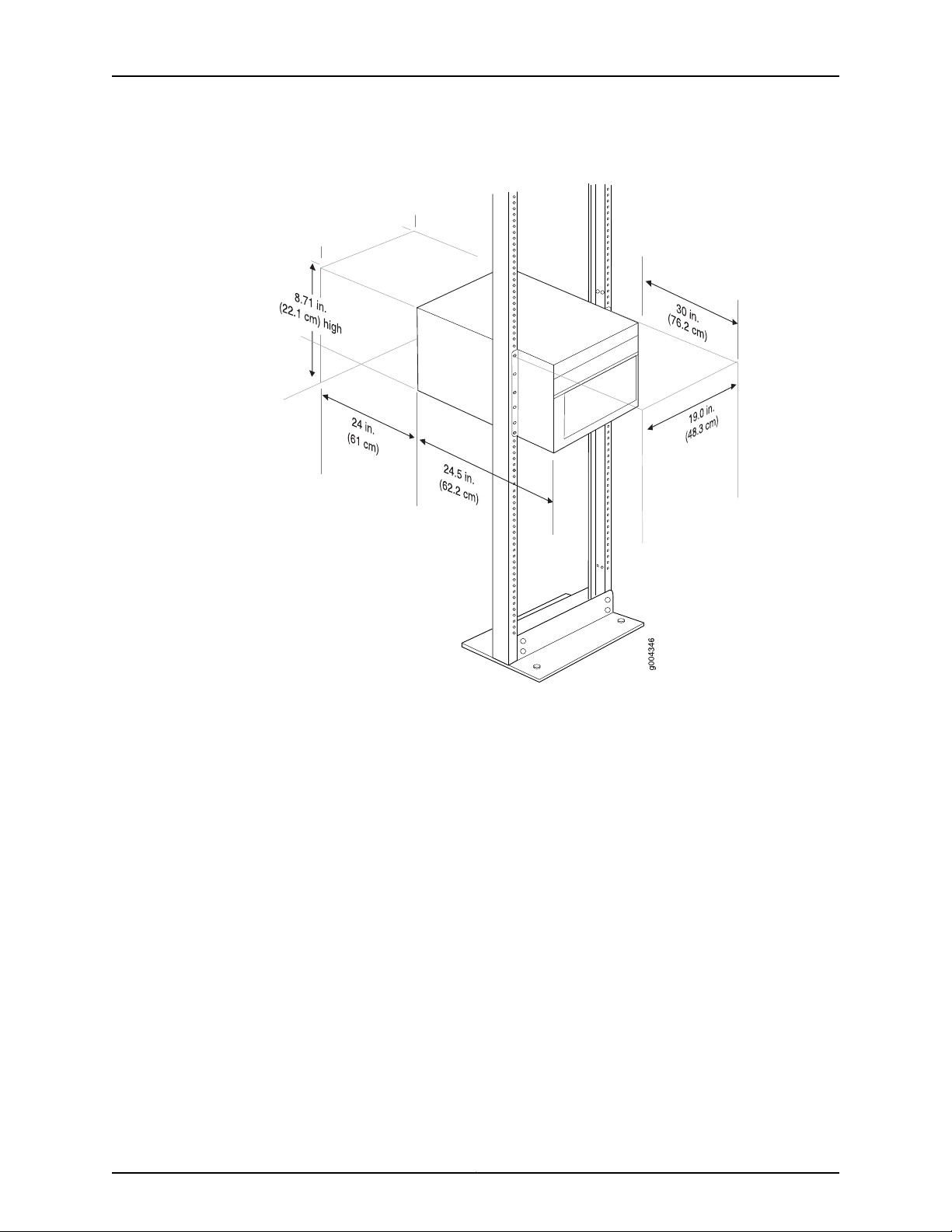
The rack rails must be spaced widely enough to accommodate the router chassis's
external dimensions: 8.71 in. (22.1 cm) high, 24.5 in. (62.2 cm) deep, and
17.45 in. (44.3 cm) wide. The mounting brackets extend the width to 19 in. (48.3 cm).
•
The rack must be strong enough to support the weight of the fully configured router,
up to 128 lb (58.1 kg).
•
For the cooling system to function properly, the airflow around the chassis must be
unrestricted. Allow at least 6 in. (15.2 cm) of clearance between side-cooled routers.
Allow 2.8 in. (7 cm) between the side of the chassis and any non-heat-producing
surface such as a wall.
•
For service personnel to remove and install hardware components, there must be
adequate space at the front and back of the router. Allow at least 30 in. (76.2 cm) in
front of the router and 24 in. (61 cm) behind the router.
•
The rack or cabinet must have an adequate supply of cooling air.
•
Ensure that the cabinet allows the chassis hot exhaust air to exit from the cabinet
without recirculating into the router.
•
The router must be installed into a rack that is secured to the building structure.
•
Mount the router at the bottom of the rack if it is the only unit in the rack.
•
When mounting the router in a partially filled rack, load the rack from the bottom to
the top with the heaviest component at the bottom of the rack.
Copyright © 2015, Juniper Networks, Inc.4
Tools Required to Unpack and Prepare the MX240 Router for Installation
Figure 1: MX240 Rack Clearance and Router Dimensions
Tools Required to Unpack and Prepare the MX240 Router for Installation
To unpack the router and prepare for installation, you need the following tools:
•
A mechanical lift—recommended
•
Phillips (+) screwdrivers, numbers 1 and 2
•
2.5-mm flat-blade (–) screwdriver
•
7/16-in. (11 mm) torque-controlled driver or socket wrench
•
1/2-in. or 13-mm open-end or socket wrench to remove bracket bolts from the shipping
pallet
•
Electrostatic discharge wrist strap
•
Antistatic mat
Proceed to “Step 2: Install the Mounting Hardware in a Four-Post Rack or Cabinet or an
Open-Frame Rack” on page 6.
5Copyright © 2015, Juniper Networks, Inc.
MX240 3D Universal Edge Router Quick Start
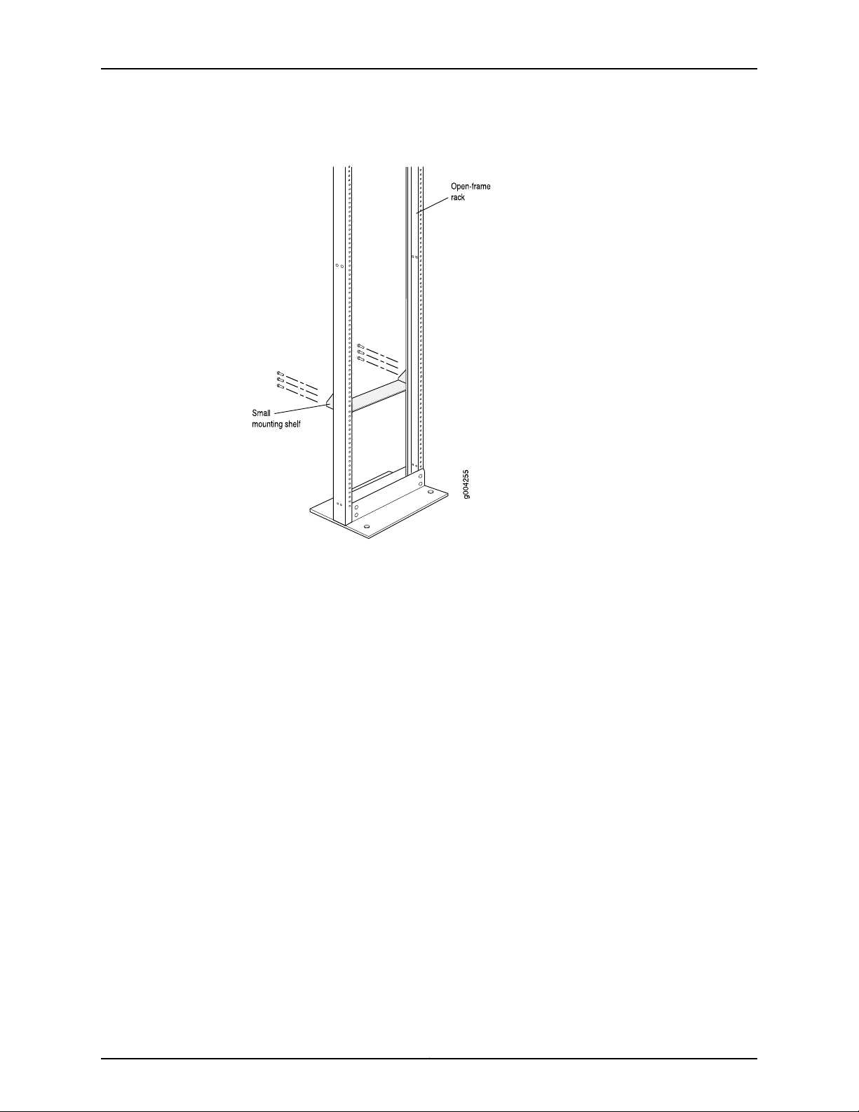
Step2: Install the Mounting Hardware in a Four-Post Rack or Cabinet or an Open-Frame Rack
To install the mounting shelf on the front rails of a four-post rack or cabinet, or the rails
of an open-frame rack:
1. If needed, install cage nuts in the holes specified in Table 1 on page 6.
2. On the back of each rack rail, partially insert a mounting screw into the lowest hole
specified in Table 1 on page 6.
3. Install the mounting shelf on the back of the rack rails. Rest the bottom slot of each
flange on a mounting screw.
4. Partially insert screws into the open holes in each flange of the mounting shelf (see
Figure 2 on page 7 or Figure 3 on page 8).
5. Tighten all the screws completely.
Table 1: MX240 Mounting Hole Locations
Mounting ShelfDistance Above U DivisionHole
X1.14 U2.00 in. (5.1 cm)4
X0.86 U1.51 in. (3.8 cm)3
X0.50 U0.88 in. (2.2 cm)2
X0.14 U0.25 in. (0.6 cm)1
Copyright © 2015, Juniper Networks, Inc.6
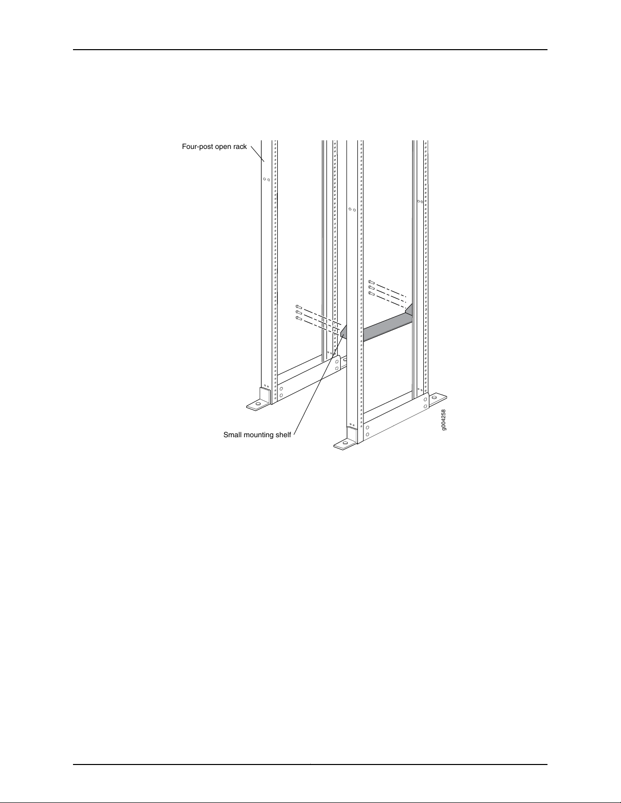
g004258
Four-post open rack
Small mounting shelf
Step 2: Install the Mounting Hardware in a Four-Post Rack or Cabinet or an Open-Frame Rack
Figure 2: Mounting Hardware for a Four-Post Rack or Cabinet
7Copyright © 2015, Juniper Networks, Inc.
MX240 3D Universal Edge Router Quick Start
Figure 3: Mounting Hardware for an Open-Frame Rack
Proceed to “Step 3: Install the Router” on page 9.
Copyright © 2015, Juniper Networks, Inc.8
Step 3: Install the Router
Because of the router's size and weight, you must remove all components before installing
the router. We also recommend that you install the router using a mechanical lift.
•
Remove Components on page 9
•
Install the Router Using a Lift on page 10
•
Install the Router Without a Mechanical Lift on page 12
•
Reinstall Components on page 13
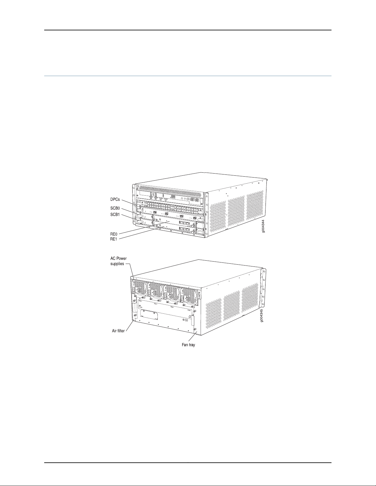
Remove Components
Figure 4: Components to Remove from the Front of the MX240 Router
Step 3: Install the Router
Figure 5: Components to Remove from the Rear of the MX240 Router
Before lifting the router, you must remove the following components:
•
Power supplies
•
Switch Control Boards (SCBs)
•
Routing Engines
•
Air filter
•
Fan tray
•
Line cards:
9Copyright © 2015, Juniper Networks, Inc.
MX240 3D Universal Edge Router Quick Start
•
Dense Port Concentrators (DPCs)
•
Flexible PIC Concentrators (FPCs)
•
Physical Interface Cards (PICs)
•
Modular Port Concentrators (MPCs)
•
Modular Interface Cards (MICs)
To remove the components from the router:
1. Slide each component out of the chassis evenly so that it does not become stuck or
damaged.
2. Label each component as you remove it so you can reinstall it in the correct location.
3. Immediately store each removed component in an electrostatic bag.
4. Do not stack removed components. Lay each one on a flat surface.
Install the Router Using a Lift
To install the router using a lift:
1. Ensure that the rack is in its permanent location and is secured to the building. Ensure
that the installation site allows adequate clearancefor both airflow and maintenance.
For details, see the MX240 3D Universal Edge Router Hardware Guide.
2. Load the router onto the lift, making sure it rests securely on the lift platform (see
Figure 6 on page 11).
NOTE: For complete instructions on removing router components, see
“Installing the MX240 Chassis in the Rack Manually” in the MX240 3D Universal
Edge Router Hardware Guide.
Copyright © 2015, Juniper Networks, Inc.10
 Loading...