

Page 1

MX204 Universal Routing Platform
Published
2020-11-11
Hardware Guide
Page 2

Juniper Networks, Inc.
1133 Innovation Way
Sunnyvale, California 94089
USA
408-745-2000
www.juniper.net
Juniper Networks, the Juniper Networks logo, Juniper, and Junos are registered trademarks of Juniper Networks, Inc. in
the United States and other countries. All other trademarks, service marks, registered marks, or registered service marks
are the property of their respective owners.
Juniper Networks assumes no responsibility for any inaccuracies in this document. Juniper Networks reserves the right
to change, modify, transfer, or otherwise revise this publication without notice.
MX204 Universal Routing Platform Hardware Guide
Copyright © 2020 Juniper Networks, Inc. All rights reserved.
The information in this document is current as of the date on the title page.
ii
YEAR 2000 NOTICE
Juniper Networks hardware and software products are Year 2000 compliant. Junos OS has no known time-related
limitations through the year 2038. However, the NTP application is known to have some difficulty in the year 2036.
END USER LICENSE AGREEMENT
The Juniper Networks product that is the subject of this technical documentation consists of (or is intended for use with)
Juniper Networks software. Use of such software is subject to the terms and conditions of the End User License Agreement
(“EULA”) posted at https://support.juniper.net/support/eula/. By downloading, installing or using such software, you
agree to the terms and conditions of that EULA.
Page 3

Table of Contents
1
About the Documentation | x
Documentation and Release Notes | x
Using the Examples in This Manual | x
Merging a Full Example | xi
Merging a Snippet | xii
Documentation Conventions | xii
Documentation Feedback | xv
Requesting Technical Support | xv
Self-Help Online Tools and Resources | xvi
Creating a Service Request with JTAC | xvi
iii
Overview
MX204 Router Overview | 18
Benefits of MX204 Router | 18
System Overview | 19
MX204 Chassis | 20
MX204 Chassis Description | 20
MX204 Component Redundancy | 22
MX204 Field-Replaceable Units | 23
MX204 Hardware Components and CLI Terminology | 23
MX204 Front and Rear Panel Components | 24
Front Panel Components | 24
Rear Panel Components | 25
Alarm LEDs on the MX204 Front Panel | 25
MX204 Cooling System | 26
MX204 Cooling System Description | 26
Fan Trays | 26
Airflow | 27
Power Supply Cooling System | 28
MX204 Fan Status LED | 28
Page 4

MX204 AC Power System | 29
2
MX204 Power System Description | 30
AC Power Supply Description | 31
DC Power Supply Description | 31
MX204 Power Supply Module LEDs | 32
AC Power Supply Module LEDs | 32
DC Power Supply Module LEDs | 34
MX204 Router AC Power Specifications | 35
AC Power Circuit Breaker Requirements for the MX204 Router | 36
AC Power Cord Specifications for MX204 Routers | 37
MX204 DC Power System | 39
MX204 Router DC Power Specifications | 39
DC Power Circuit Breaker Requirements for the MX204 Router | 40
iv
DC Power Source Cabling for MX204 Router | 41
DC Power Cable Specifications for MX204 Router | 42
DC Power Cable Lug Specifications | 42
DC Power Cable Specifications | 42
MX204 Host Subsystem | 43
MX204 Routing Engine Description | 43
Routing Engine Functions | 43
Routing Engine Components | 44
Routing Engine Front Panel | 44
Routing Engine Interface Ports | 45
MX204 Routing Engine LEDs | 46
Site Planning, Preparation, and Specifications
MX204 Site Preparation Checklist | 50
MX204 Site Guidelines and Requirements | 51
MX204 Router Physical Specifications | 52
MX204 Router Environmental Specifications | 52
MX204 Router Grounding Specifications | 54
Grounding Points Specifications | 54
Grounding Cable Lug Specifications | 54
Page 5

Grounding Cable Specifications | 55
MX204 Router Cabinet Requirements and Specifications | 55
MX204 Router Clearance Requirements for Airflow and Hardware Maintenance | 57
MX204 Router Rack Requirements | 58
MX204 Network Cable and Transceiver Planning | 60
Calculating Power Budget and Power Margin for Fiber-Optic Cables | 60
How to Calculate Power Budget for Fiber-Optic Cable | 60
How to Calculate Power Margin for Fiber-Optic Cable | 61
CB-RE and RCB Interface Cable and Wire Specifications for MX Series Routers | 62
Fiber-Optic Cable Signal Loss, Attenuation, and Dispersion | 63
Signal Loss in Multimode and Single-Mode Fiber-Optic Cable | 63
Attenuation and Dispersion in Fiber-Optic Cable | 64
MX204 Management and Console Port Specifications and Pinouts | 65
v
RJ-45 Connector Pinouts for MX Series CB-RE or RCB Auxillary and Console Ports | 65
RJ-45 Connector Pinouts for an MX Series CB-RE or RCB Management Port | 66
MX204 Power Planning | 67
Power Consumption for an AC-Powered MX204 Router | 67
Power Requirements for MX204 Components | 67
Calculating System Thermal Output | 68
Power Consumption for a DC-Powered MX204 Router | 69
Power Requirements for MX204 Components | 69
Calculating System Thermal Output | 70
Page 6

Initial Installation and Configuration
3
MX204 Installation Overview | 72
Unpacking the MX204 | 73
Tools and Parts Required to Unpack the MX204 Router | 73
Unpacking MX204 Router | 74
Verifying the MX204 Router Parts Received | 75
Installing the MX204 | 76
Tools Required to Install the MX204 Chassis in Rack | 77
Installing the MX204 Chassis in a Rack | 77
Installing the MX204 Chassis in a 19-in. Rack | 78
Installing the MX204 in a 21-in. ETSI Rack | 80
Connecting the MX204 to Power | 84
vi
Tools and Parts Required for MX204 Router Grounding and Power Connections | 84
Grounding the MX204 Router | 85
Connecting Power to an AC-Powered MX204 Router | 86
Powering On an AC-Powered MX204 Router | 89
Connecting Power to a DC-Powered MX204 Router | 90
Powering On a DC-Powered MX204 Router | 93
Powering Off the MX204 Router | 94
Connecting the MX204 to the Network | 96
Tools and Parts Required to Connect the MX204 Router to External Devices | 96
Connecting the MX204 Router to External Devices and Cables | 96
Connecting the Router to a Network for Out-of-Band Management | 97
Connecting the Router to a Console Device | 98
Connecting the Router to External Clocking and Timing Devices | 100
Performing the Initial Software Configuration for the MX204 Router | 103
Page 7

Maintaining Components
4
5
Maintaining MX204 Components | 109
Routine Maintenance Procedures for MX204 Routers | 109
Maintaining the MX204 Routing Engine | 109
Replace an SFP, SFP+, or QSFP+ Transceiver | 111
Remove a Transceiver | 111
Install a Transceiver | 113
Replace a QSFP28 Transceiver | 115
Remove a QSFP28 Transceiver | 116
Install a QSFP28 Transceiver | 117
Maintaining MX204 Cooling System Components | 120
Maintaining the MX204 Fan Module | 120
Replacing an MX204 Fan Module | 121
vii
Removing an MX204 Fan Module | 122
Installing an MX204 Fan Module | 123
Maintaining MX204 Power System Components | 124
Maintaining the MX204 Power Supplies | 124
Replacing an MX204 AC Power Supply | 126
Removing an MX204 AC Power Supply | 126
Installing an MX204 AC Power Supply | 127
Replacing an MX204 DC Power Supply | 128
Removing an MX204 DC Power Supply | 128
Installing an MX204 DC Power Supply | 130
Contacting Customer Support and Returning the Chassis or Components
Contacting Customer Support and Returning the Chassis or Components | 134
Contacting Customer Support | 134
Contact Customer Support to Obtain Return Material Authorization | 135
Locating the Serial Number on an MX204 Router or Component | 136
Listing the Chassis and Component Details Using the CLI | 136
Locating the Chassis Serial Number ID Label on an MX204 | 137
Locating the Serial Number ID Labels on MX204 Power Supplies | 137
Page 8

Locating the Serial Number ID Label on an MX204 Fan Module | 138
6
Guidelines for Packing Hardware Components for Shipment | 139
Safety and Compliance Information
Definitions of Safety Warning Levels | 142
General Safety Guidelines and Warnings | 145
General Safety Warnings for Juniper Networks Devices | 146
Qualified Personnel Warning | 147
Restricted-Access Area Warning | 148
Fire Safety Requirements | 150
Fire Suppression | 150
Fire Suppression Equipment | 151
Installation Instructions Warning | 152
viii
Chassis and Component Lifting Guidelines | 152
Ramp Warning | 153
Rack-Mounting and Cabinet-Mounting Warnings | 153
Laser and LED Safety Guidelines and Warnings | 158
General Laser Safety Guidelines | 159
Class 1 Laser Product Warning | 160
Class 1 LED Product Warning | 161
Laser Beam Warning | 162
Radiation from Open Port Apertures Warning | 163
Maintenance and Operational Safety Guidelines and Warnings | 164
Battery Handling Warning | 165
Jewelry Removal Warning | 166
Lightning Activity Warning | 168
Operating Temperature Warning | 169
Product Disposal Warning | 171
General Electrical Safety Guidelines and Warnings | 172
Page 9

Prevention of Electrostatic Discharge Damage | 173
Site Electrical Wiring Guidelines | 174
AC Power Electrical Safety Guidelines | 175
AC Power Disconnection Warning | 177
DC Power Disconnection Warning | 178
DC Power Grounding Requirements and Warning | 180
DC Power Wiring Sequence Warning | 182
DC Power Wiring Terminations Warning | 185
Multiple Power Supplies Disconnection Warning | 188
TN Power Warning | 189
ix
Action to Take After an Electrical Accident | 189
Agency Approvals for MX204 Router | 190
Compliance Statements for NEBS | 192
Compliance Statements for EMC Requirements | 192
Canada | 192
European Community | 192
Israel | 193
Japan | 193
United States | 193
Compliance Statements for Environmental Requirements | 194
Compliance Statements for Acoustic Noise for MX204 Router | 194
Statements of Volatility for Juniper Network Devices | 194
Page 10
About the Documentation
IN THIS SECTION
Documentation and Release Notes | x
Using the Examples in This Manual | x
Documentation Conventions | xii
Documentation Feedback | xv
Requesting Technical Support | xv
Use this guide to install hardware and perform initial software configuration, routine maintenance, and
troubleshooting for the MX204 Universal Routing Platform. After completing the installation and basic
configuration procedures covered in this guide, refer to the Junos OS documentation for information about
further software configuration.
x
Documentation and Release Notes
To obtain the most current version of all Juniper Networks®technical documentation, see the product
documentation page on the Juniper Networks website at https://www.juniper.net/documentation/.
If the information in the latest release notes differs from the information in the documentation, follow the
product Release Notes.
Juniper Networks Books publishes books by Juniper Networks engineers and subject matter experts.
These books go beyond the technical documentation to explore the nuances of network architecture,
deployment, and administration. The current list can be viewed at https://www.juniper.net/books.
Using the Examples in This Manual
If you want to use the examples in this manual, you can use the load merge or the load merge relative
command. These commands cause the software to merge the incoming configuration into the current
candidate configuration. The example does not become active until you commit the candidate configuration.
Page 11

If the example configuration contains the top level of the hierarchy (or multiple hierarchies), the example
is a full example. In this case, use the load merge command.
If the example configuration does not start at the top level of the hierarchy, the example is a snippet. In
this case, use the load merge relative command. These procedures are described in the following sections.
Merging a Full Example
To merge a full example, follow these steps:
1. From the HTML or PDF version of the manual, copy a configuration example into a text file, save the
file with a name, and copy the file to a directory on your routing platform.
For example, copy the following configuration to a file and name the file ex-script.conf. Copy the
ex-script.conf file to the /var/tmp directory on your routing platform.
system {
scripts {
commit {
file ex-script.xsl;
}
}
}
interfaces {
fxp0 {
disable;
unit 0 {
family inet {
address 10.0.0.1/24;
}
}
}
}
xi
2. Merge the contents of the file into your routing platform configuration by issuing the load merge
configuration mode command:
[edit]
user@host# load merge /var/tmp/ex-script.conf
load complete
Page 12

Merging a Snippet
To merge a snippet, follow these steps:
1. From the HTML or PDF version of the manual, copy a configuration snippet into a text file, save the
file with a name, and copy the file to a directory on your routing platform.
For example, copy the following snippet to a file and name the file ex-script-snippet.conf. Copy the
ex-script-snippet.conf file to the /var/tmp directory on your routing platform.
commit {
file ex-script-snippet.xsl; }
2. Move to the hierarchy level that is relevant for this snippet by issuing the following configuration mode
command:
[edit]
user@host# edit system scripts
[edit system scripts]
xii
3. Merge the contents of the file into your routing platform configuration by issuing the load merge
relative configuration mode command:
[edit system scripts]
user@host# load merge relative /var/tmp/ex-script-snippet.conf
load complete
For more information about the load command, see CLI Explorer.
Documentation Conventions
Table 1 on page xiii defines notice icons used in this guide.
Page 13
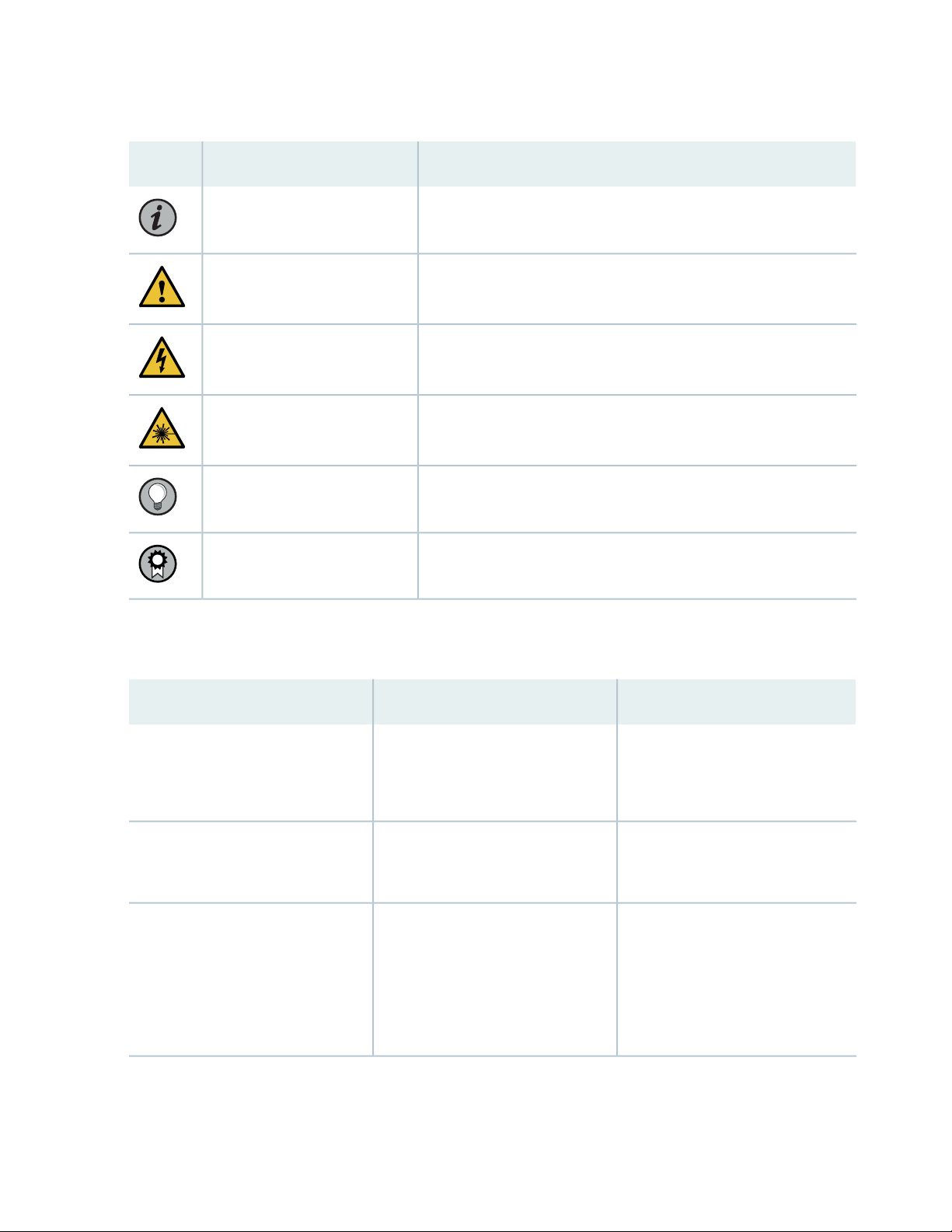
Table 1: Notice Icons
xiii
DescriptionMeaningIcon
Indicates important features or instructions.Informational note
Caution
Indicates a situation that might result in loss of data or hardware
damage.
Alerts you to the risk of personal injury or death.Warning
Alerts you to the risk of personal injury from a laser.Laser warning
Indicates helpful information.Tip
Alerts you to a recommended use or implementation.Best practice
Table 2 on page xiii defines the text and syntax conventions used in this guide.
Table 2: Text and Syntax Conventions
ExamplesDescriptionConvention
Fixed-width text like this
Italic text like this
Represents text that you type.Bold text like this
Represents output that appears on
the terminal screen.
Introduces or emphasizes important
•
new terms.
Identifies guide names.
•
Identifies RFC and Internet draft
•
titles.
To enter configuration mode, type
the configure command:
user@host> configure
user@host> show chassis alarms
No alarms currently active
A policy term is a named structure
•
that defines match conditions and
actions.
Junos OS CLI User Guide
•
RFC 1997, BGP Communities
•
Attribute
Page 14

Table 2: Text and Syntax Conventions (continued)
xiv
ExamplesDescriptionConvention
Italic text like this
Text like this
< > (angle brackets)
| (pipe symbol)
Represents variables (options for
which you substitute a value) in
commands or configuration
statements.
Represents names of configuration
statements, commands, files, and
directories; configuration hierarchy
levels; or labels on routing platform
components.
variables.
Indicates a choice between the
mutually exclusive keywords or
variables on either side of the symbol.
The set of choices is often enclosed
in parentheses for clarity.
Configure the machine’s domain
name:
[edit]
root@# set system domain-name
domain-name
To configure a stub area, include
•
the stub statement at the [edit
protocols ospf area area-id]
hierarchy level.
The console port is labeled
•
CONSOLE.
stub <default-metric metric>;Encloses optional keywords or
broadcast | multicast
(string1 | string2 | string3)
# (pound sign)
[ ] (square brackets)
Indention and braces ( { } )
; (semicolon)
GUI Conventions
Indicates a comment specified on the
same line as the configuration
statement to which it applies.
Encloses a variable for which you can
substitute one or more values.
Identifies a level in the configuration
hierarchy.
Identifies a leaf statement at a
configuration hierarchy level.
rsvp { # Required for dynamic MPLS
only
community name members [
community-ids ]
[edit]
routing-options {
static {
route default {
nexthop address;
retain;
}
}
}
Page 15
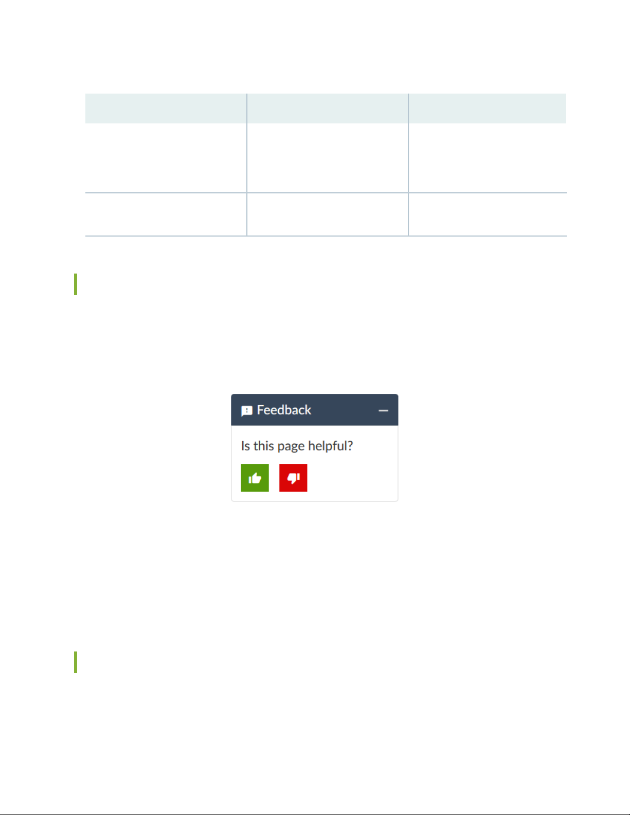
Table 2: Text and Syntax Conventions (continued)
xv
ExamplesDescriptionConvention
Bold text like this
> (bold right angle bracket)
Represents graphical user interface
(GUI) items you click or select.
Separates levels in a hierarchy of
menu selections.
In the Logical Interfaces box, select
•
All Interfaces.
To cancel the configuration, click
•
Cancel.
In the configuration editor hierarchy,
select Protocols>Ospf.
Documentation Feedback
We encourage you to provide feedback so that we can improve our documentation. You can use either
of the following methods:
Online feedback system—Click TechLibrary Feedback, on the lower right of any page on the Juniper
•
Networks TechLibrary site, and do one of the following:
Click the thumbs-up icon if the information on the page was helpful to you.
•
Click the thumbs-down icon if the information on the page was not helpful to you or if you have
•
suggestions for improvement, and use the pop-up form to provide feedback.
E-mail—Send your comments to techpubs-comments@juniper.net. Include the document or topic name,
•
URL or page number, and software version (if applicable).
Requesting Technical Support
Technical product support is available through the Juniper Networks Technical Assistance Center (JTAC).
If you are a customer with an active Juniper Care or Partner Support Services support contract, or are
Page 16

covered under warranty, and need post-sales technical support, you can access our tools and resources
online or open a case with JTAC.
JTAC policies—For a complete understanding of our JTAC procedures and policies, review the JTAC User
•
Guide located at https://www.juniper.net/us/en/local/pdf/resource-guides/7100059-en.pdf.
Product warranties—For product warranty information, visit https://www.juniper.net/support/warranty/.
•
JTAC hours of operation—The JTAC centers have resources available 24 hours a day, 7 days a week,
•
365 days a year.
Self-Help Online Tools and Resources
For quick and easy problem resolution, Juniper Networks has designed an online self-service portal called
the Customer Support Center (CSC) that provides you with the following features:
Find CSC offerings: https://www.juniper.net/customers/support/
•
Search for known bugs: https://prsearch.juniper.net/
•
xvi
Find product documentation: https://www.juniper.net/documentation/
•
Find solutions and answer questions using our Knowledge Base: https://kb.juniper.net/
•
Download the latest versions of software and review release notes:
•
https://www.juniper.net/customers/csc/software/
Search technical bulletins for relevant hardware and software notifications:
•
https://kb.juniper.net/InfoCenter/
Join and participate in the Juniper Networks Community Forum:
•
https://www.juniper.net/company/communities/
Create a service request online: https://myjuniper.juniper.net
•
To verify service entitlement by product serial number, use our Serial Number Entitlement (SNE) Tool:
https://entitlementsearch.juniper.net/entitlementsearch/
Creating a Service Request with JTAC
You can create a service request with JTAC on the Web or by telephone.
Visit https://myjuniper.juniper.net.
•
Call 1-888-314-JTAC (1-888-314-5822 toll-free in the USA, Canada, and Mexico).
•
For international or direct-dial options in countries without toll-free numbers, see
https://support.juniper.net/support/requesting-support/.
Page 17

1
CHAPTER
Overview
MX204 Router Overview | 18
MX204 Chassis | 20
MX204 Cooling System | 26
MX204 AC Power System | 29
MX204 DC Power System | 39
MX204 Host Subsystem | 43
Page 18

MX204 Router Overview
The Juniper Networks MX204 Universal Routing Platform is an Ethernet-optimized edge router with
400-Gbps capacity that provides both switching and carrier-class Ethernet routing. The MX204 router
runs Junos operating system (Junos OS), enabling a wide range of business and residential applications
and services, including high-speed transport and virtual private network (VPN) services, next-generation
broadband multiplay services, and high-volume Internet data center internetworking. Each router provides
full duplex, high-density Ethernet interfaces and high-capacity switching throughput and uses the Junos
Trio chipset for increased scalability of Layer 2 and Layer 3 packet forwarding, buffering, and queuing.
Benefits of MX204 Router
System Capacity—MX204 provides 400 Gbps of throughput and supports high-density 100-Gigabit
•
Ethernet interfaces, and also discrete and breakout 10-Gigabit Ethernet and 1-Gigabit Ethernet
interfaces—all in a single rack unit while consuming only 0.9 W/Gb.
18
The Programmable Chipset—The chipset implemented in the MX Series routers has a programmable
•
forwarding data structure that allows fast microcode changes in the hardware itself, and a programmable
lookup engine that allows inline service processing. the chip’s programmable QoS engine supports coarse
and fine-grained queuing to address the requirements of core, edge, and aggregation use cases.
Application-Aware Networking—On MX Series routers you can use deep packet inspection to detect
•
applications, and by using the user-defined policies, you can determine traffic treatment for each
application. This feature enables highly customized and differentiated services at scale.
Junos Telemetry Interface—Using the Junos telemetry interface data, you can stream component-level
•
data to monitor, analyze, and enhance the performance of the network. Analytics derived from this
streaming telemetry can identify current and trending congestion, resource utilization, traffic volume,
and buffer occupancy.
Integrated Hardware-Based Timing— You do not need to use external clocks because MX Series routers
•
support highly scalable and reliable hardware-based timing, including Synchronous Ethernet for frequency,
and the Precision Time Protocol (PTP) for frequency and phase synchronization. Synchronous Ethernet
and PTP can be combined in a hybrid mode to achieve a high level of frequency (10 ppb) and phase (<1.5
uS) accuracy.
Page 19
System Overview
g009860
g0 09861
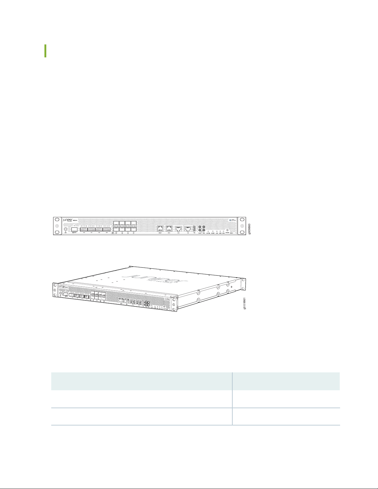
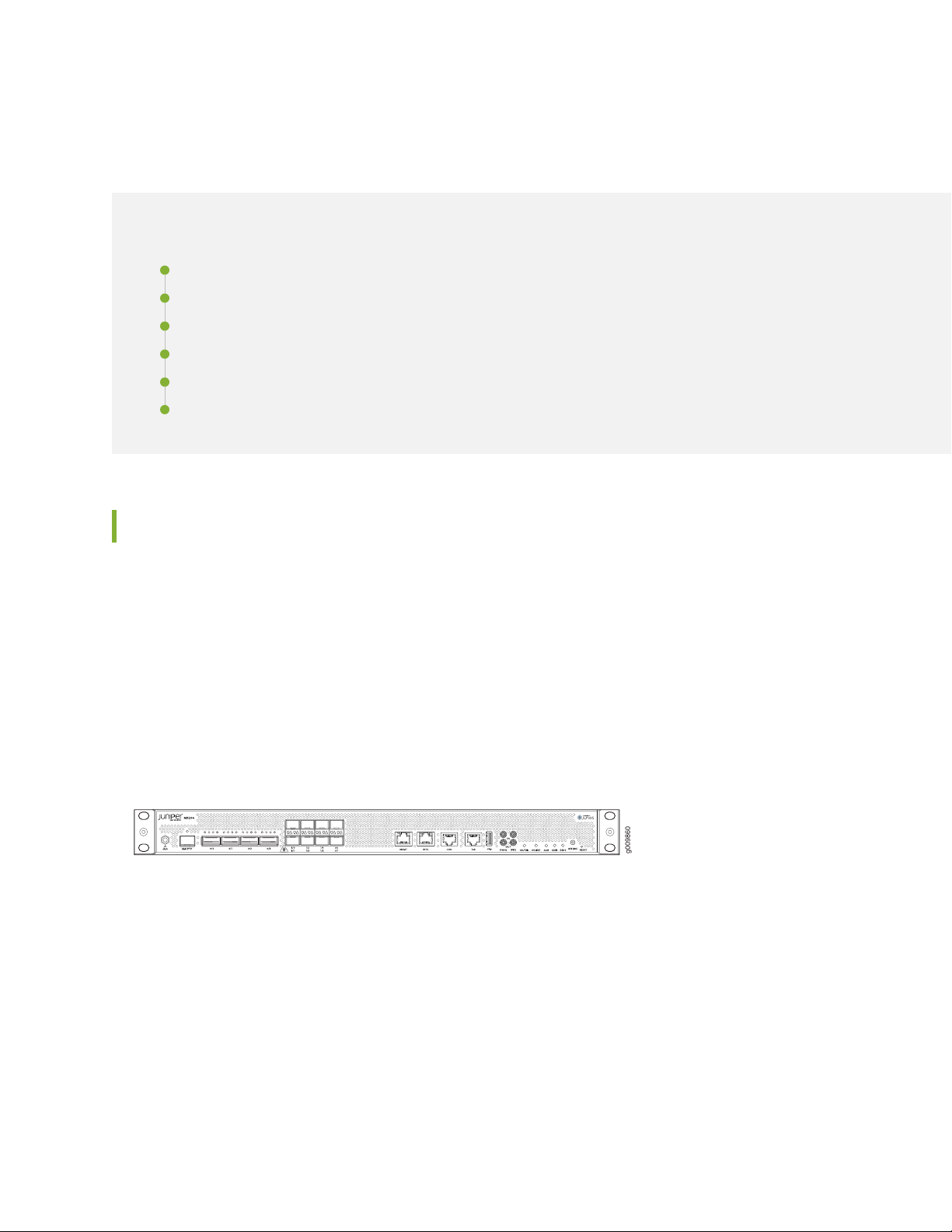
The MX204 router is compact and one rack unit (1 U) tall. Several routers can be stacked in a single
floor-to-ceiling rack for increased port density per unit of floor space.
The MX204 router is a fixed-configuration router, and supports one built-in Routing Engine. The router
runs on AC or DC power, with two dedicated power supply modules on each device. Cooling is handled
by three fan modules.
The MX204 has four rate-selectable ports that can be configured as 100-Gigabit Ethernet ports or 40-Gigabit
Ethernet ports, or each port can be configured as four 10-Gigabit Ethernet ports (by using a breakout
cable). The MX204 also has eight 10-Gigabit Ethernet ports. The four rate-selectable ports support QSFP28
and QSFP+ transceivers, whereas the eight 10-Gigabit Ethernet ports support SFP+ transceivers.
Figure 1 on page 19 shows the front view of the MX204 router.
Figure 1: Front View of the MX204 Router
19
The MX204 router is a fixed-configuration router, and supports one built-in Routing Engine. The router
runs on AC or DC power, with two dedicated power supply modules on each device. Cooling is handled
by three fan modules. Table 3 on page 19 shows the components supported on the router.
Table 3: MX204 Router Components
DescriptionComponent
2Power supply module
3Fan module
Page 20
MX204 Chassis
g009860
IN THIS SECTION
MX204 Chassis Description | 20
MX204 Component Redundancy | 22
MX204 Field-Replaceable Units | 23
MX204 Hardware Components and CLI Terminology | 23
MX204 Front and Rear Panel Components | 24
Alarm LEDs on the MX204 Front Panel | 25
20
MX204 Chassis Description
The router chassis is a rigid sheet metal structure that houses all the other router components.
Figure 2 on page 20 shows the front of the fully configured chassis. The chassis measures 1.72 in. (4.37 cm)
high, 19 in. (48.26 cm) wide, and 18.5 in. (47.0 cm) deep. You can install the router chassis in standard
760-mm deep (or larger) enclosed cabinets, 19-in. equipment racks, or telco open-frame racks. The total
weight of fully loaded router is 22.7 lb (10.3 kg). For more information, see “MX204 Router Physical
Specifications” on page 52.
Figure 2: Front View of the MX204 Router
The MX204 has four rate-selectable ports that can be configured as 100-Gigabit Ethernet ports or 40-Gigabit
Ethernet ports, or each port can be configured as four 10-Gigabit Ethernet ports (by using a breakout
cable). The MX204 also has eight 10-Gigabit Ethernet ports. The four rate-selectable ports support QSFP28
and QSFP+ transceivers, whereas the eight 10-Gigabit Ethernet ports support SFP+ transceivers. For more
information on the rate selectability support for the MX204 router, see MX204 Router Port Speed Overview.
Starting in Junos OS Release 18.3R1, you can use the Mellanox 10-Gbps pluggable adapter (QSFP+ to
SFP+ adapter or QSA; model number: MAM1Q00A-QSA) to convert four lane-based ports to a single
lane-based SFP+ port. The QSA adapter has the QSFP+ form factor with a receptacle for the SFP+ module.
Page 21
Use the QSA adapter to convert a 40-Gbps port to a 10-Gbps (SFP+) or a 1-Gbps (SFP) port. The 1-Gbps
g009862
1 2
g009863
1 2
SFP port supports auto-negotiation. You can configure auto-negotiation by using the command set
interfaces interface-name gigether-options auto-negotiation. For more information, see auto-negotiation.
NOTE:
The interface name prefix must be xe.
•
Rate selectability at PIC level and port level does not support 1-Gbps speed.
•
NOTE: For a complete list of supported optics on MX204, see MX204 Transceivers.
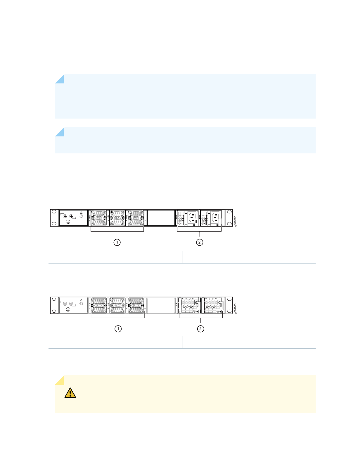
The router comes in two variants–AC-powered and DC-powered. Figure 3 on page 21 and
Figure 4 on page 21 shows the rear of the fully configured chassis.
21
Figure 3: Rear View of the AC-Powered MX204 Router
2—1— Power supply modules (AC)Fan modules
Figure 4: Rear View of the DC-Powered MX204 Router
2—1— Power supply modules (DC)Fan modules
The electrostatic discharge (ESD) points on the router are located both on the front and on the rear of the
chassis. Figure 5 on page 22 shows the electrostatic discharge (ESD) point on the router.
CAUTION: Before removing or installing components, attach an ESD strap to an ESD
point, and place the other end of the strap around your bare wrist. Failure to use an
ESD strap could result in damage to the hardware components.
Page 22
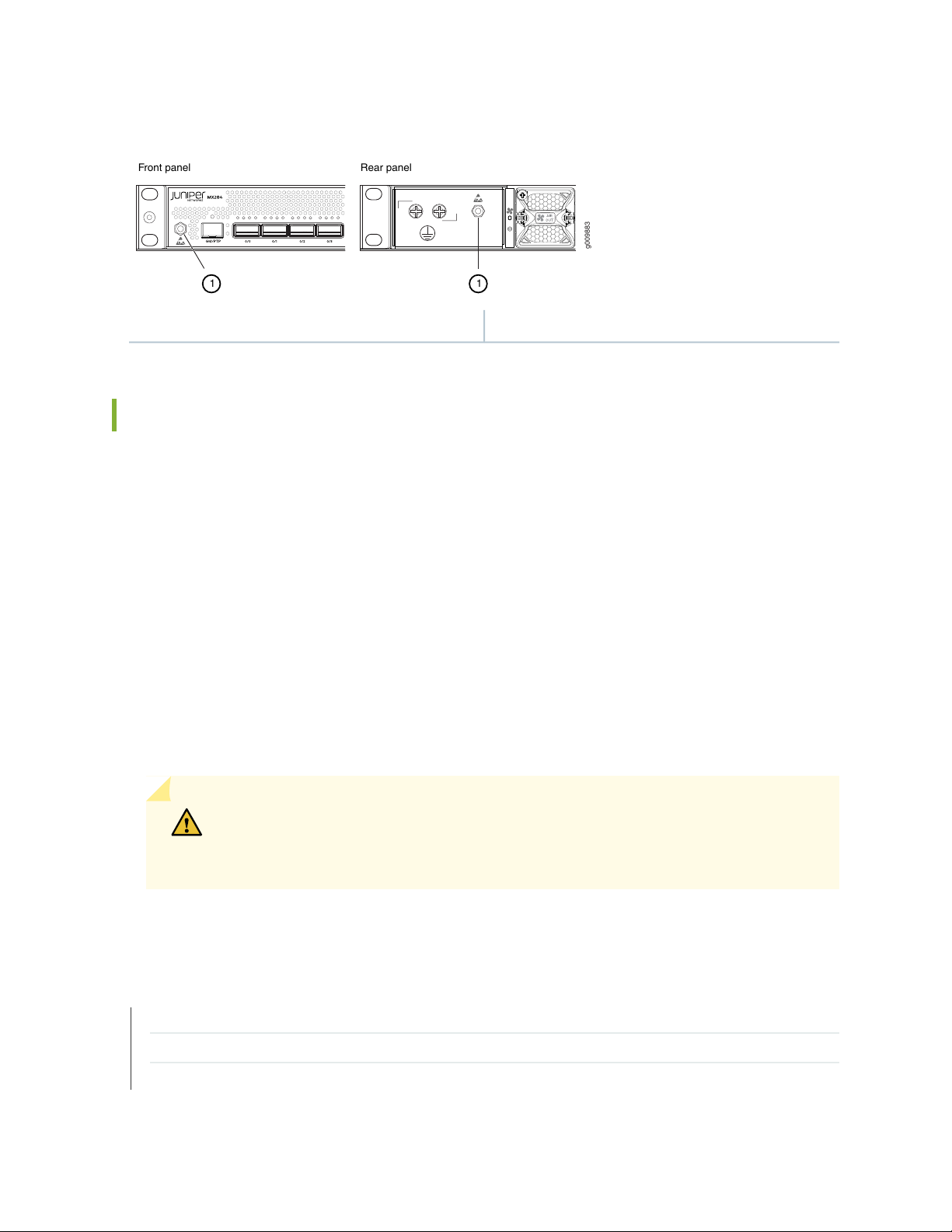
Figure 5: ESD Points on the MX204 Router
g009883
Front panel Rear panel
11
1—ESD points
MX204 Component Redundancy
A fully configured router is designed so that at no single point of failure can cause the entire system to
fail. Only a fully configured router provides complete redundancy. All other configurations provide partial
redundancy. The following major hardware components are redundant:
22
Power supplies—The router supports two power supply modules. The MX204 router provides 1+1
•
redundancy for the system. Both AC and DC systems can withstand the failure of a single power supply
without system interruption in 1+1 redundancy mode. If one power supply fails in a fully redundant
system, the other power supply can provide full power to the router indefinitely.
Cooling system—The cooling system has a total of three fan modules, which are controlled and monitored
•
by the host subsystem. A fully configured router needs all the fan modules to operate normal. The fan
modules are at the rear and are used to cool the router. If a fan fails or the temperature of the chassis
rises above the temperature threshold, the speed of the remaining fans is automatically adjusted to keep
the temperature within the acceptable range.
CAUTION: For a fully configured router, all the three fan modules and the two power
supply modules must be operational, and in the event of any module failure the failed
module must be replaced immediately.
SEE ALSO
Locating the Serial Number on an MX204 Router or Component | 136
Guidelines for Packing Hardware Components for Shipment | 139
How to Return a Hardware Component to Juniper Networks, Inc.
Page 23

MX204 Field-Replaceable Units
Field-replaceable units (FRUs) are router components that can be replaced at the customer site. Replacing
most FRUs requires minimal router downtime. The router uses the following types of FRUs:
Power supply modules (if redundant)
•
Fan modules (if redundant)
•
Transceiver modules
•
SEE ALSO
Replacing an MX204 AC Power Supply | 126
Replacing an MX204 DC Power Supply | 128
Replacing an MX204 Fan Module | 121
23
MX204 Hardware Components and CLI Terminology
The MX204 router support the components in Table 4 on page 23, listed in alphabetic order.
Table 4: MX204 Router Hardware Components and CLI Terminology
Hardware Model
DescriptionCLI Name
“MX204 Chassis Description” on
page 20
“MX204 Cooling System
Description” on page 26
“MX204 Power System
Description” on page 30
Cooling system
Power system components
Power supply module
NumberComponent
JNP-FAN-1RUFan module
JPSU-650W-AC-AO
•
JPSU-650W-DC-AFO
•
JNP204 [MX204]MX204Chassis
Fan Tray, Front to Back
Airflow - AFO
AC AFO 650W PSU
•
DC AFO 650W PSU
•
N/APICN/A (built-in)MIC
N/AFPCN/A (built-in)MPC
Page 24
Table 4: MX204 Router Hardware Components and CLI Terminology (continued)
Hardware Model
NumberComponent
DescriptionCLI Name
N/ARE-S-1600x8N/A (built-in)Routing Engine
24
Transceiver
Module Reference.
Hardware Compatibility ToolXcvrSee MX Series Interface
Table 5 on page 24 lists the spare parts and blank panels available for the router.
Table 5: MX204 Spare Parts and Blank Panels
DescriptionModel Number
MX204 chassis, spareJNP204-CHAS
MX204 power blank cover panelJNP-PWR-BLNK-1
MX204 Front and Rear Panel Components
IN THIS SECTION
Front Panel Components | 24
Rear Panel Components | 25
Front Panel Components
The front panel on the front of the router enables you to view status and troubleshooting information at
a glance. The front panel contains LEDs for the router components, online/offline and reset buttons,
auxiliary and console ports, clocking ports, and interface ports. “MX204 Chassis Description” on page 20
shows the front of the fully configured chassis.
Page 25
Rear Panel Components
The rear panel of the router has slots for the power supply modules and fan modules. The power and fan
modules are installed from the rear of the router. “MX204 Chassis Description” on page 20 and “MX204
Chassis Description” on page 20 shows the rear of the fully configured chassis.
Table 6 on page 25 lists the components on the rear panel of the MX204 router.
Table 6: Rear Panel Components in a Fully Configured MX204 Router
Number of FRUsSlotsComponent
20 and 1Power supply module
30 through 2Fan module
25
Alarm LEDs on the MX204 Front Panel
One alarm LED—labeled ALM—is located on the front panel of the router. A red light indicates a critical
condition that can result in a system shutdown, and a yellow light indicates a less severe condition that
requires monitoring or maintenance.
Table 7 on page 25 describes the alarm LED in more detail.
Table 7: Alarm LED on the MX204 Front Panel
DescriptionColorShape
Red
Yellow
Critical alarm—Indicates a critical condition that
can cause the router to stop functioning. Possible
causes include component removal, failure, or
overheating.
Warning alarm—Indicates a serious but nonfatal
error condition, such as a maintenance alert or
a significant increase in component temperature.
SEE ALSO
Routine Maintenance Procedures for MX204 Routers | 109
Page 26
MX204 Cooling System
IN THIS SECTION
MX204 Cooling System Description | 26
MX204 Fan Status LED | 28
MX204 Cooling System Description
IN THIS SECTION
26
Fan Trays | 26
Airflow | 27
Power Supply Cooling System | 28
The cooling system components work together to keep all router components within the acceptable
temperature range.
The cooling system consists of the following features and components:
Fan Trays
The chassis monitors the temperature of the router components. When the router is operating normally,
the fans function at lower than full speed. If a fan fails or the ambient temperature rises above a threshold,
the speed of the remaining fans is automatically adjusted to keep the temperature within the acceptable
range. If the ambient maximum temperature specification is exceeded and the system cannot be adequately
cooled, the Routing Engine shuts down the system by disabling output power from each power supply.
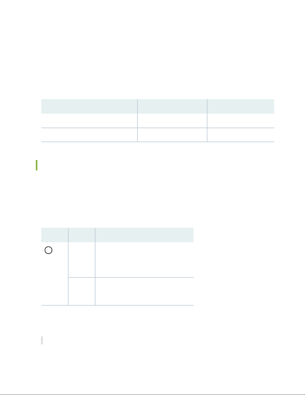
The router has three fan modules (or fan trays) that install in the rear of the router. Each fan modules
contain one counter-rotating fan. The fan modules are hot-insertable and hot-removable field-replaceable
units (FRUs) (see Figure 6 on page 27).
Page 27
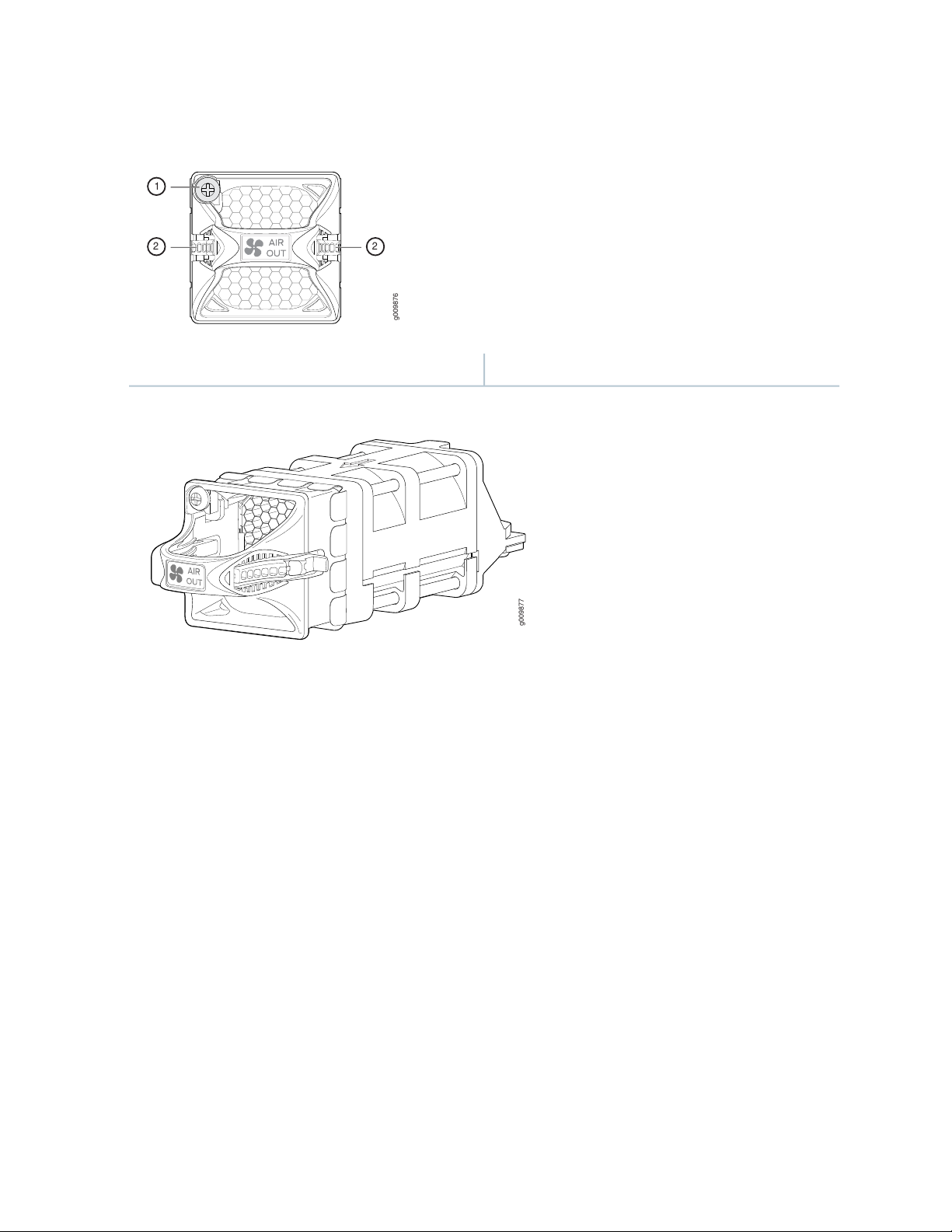
Figure 6: Fan Module
g009876
1
2 2
g009877
27
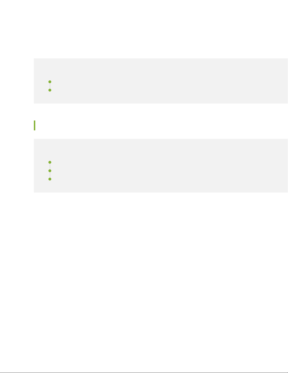
2—1— LatchCaptive screw
Airflow
The router has front-to-back (AIR OUT) cooling system (see Figure 7 on page 28). Air is pulled through
the front the chassis toward the fan tray, where it is exhausted out of the system.
Page 28
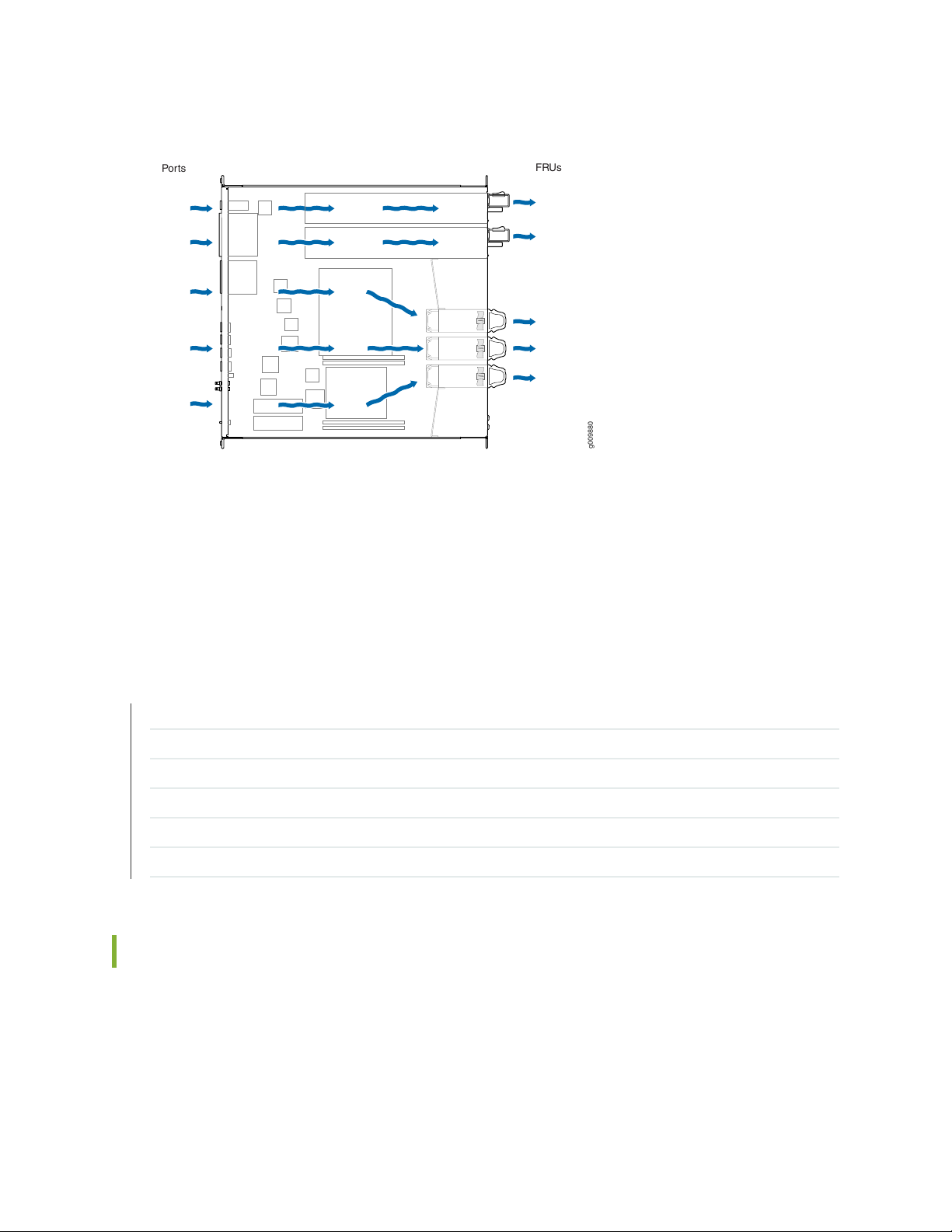
Figure 7: Airflow Through the Router
g009880
Ports
FRUs
Power Supply Cooling System
28
The power supply modules are self-cooling and are located in the rear of the router. Each power supply
module has it’s own built-in fan that cools the power supply module. The exhaust for the power supply
modules are also located on the rear of the chassis.
SEE ALSO
Maintaining the MX204 Fan Module | 120
Maintaining the MX204 Power Supplies | 124
Maintaining the MX204 Routing Engine | 109
Replacing an MX204 AC Power Supply | 126
Replacing an MX204 DC Power Supply | 128
Replacing an MX204 Fan Module | 121
MX204 Fan Status LED
The MX204 fan module does not have any LED—the fan status LEDs are located on the MX204 chassis.
Figure 8 on page 29 shows the fan status LEDs.
Page 29
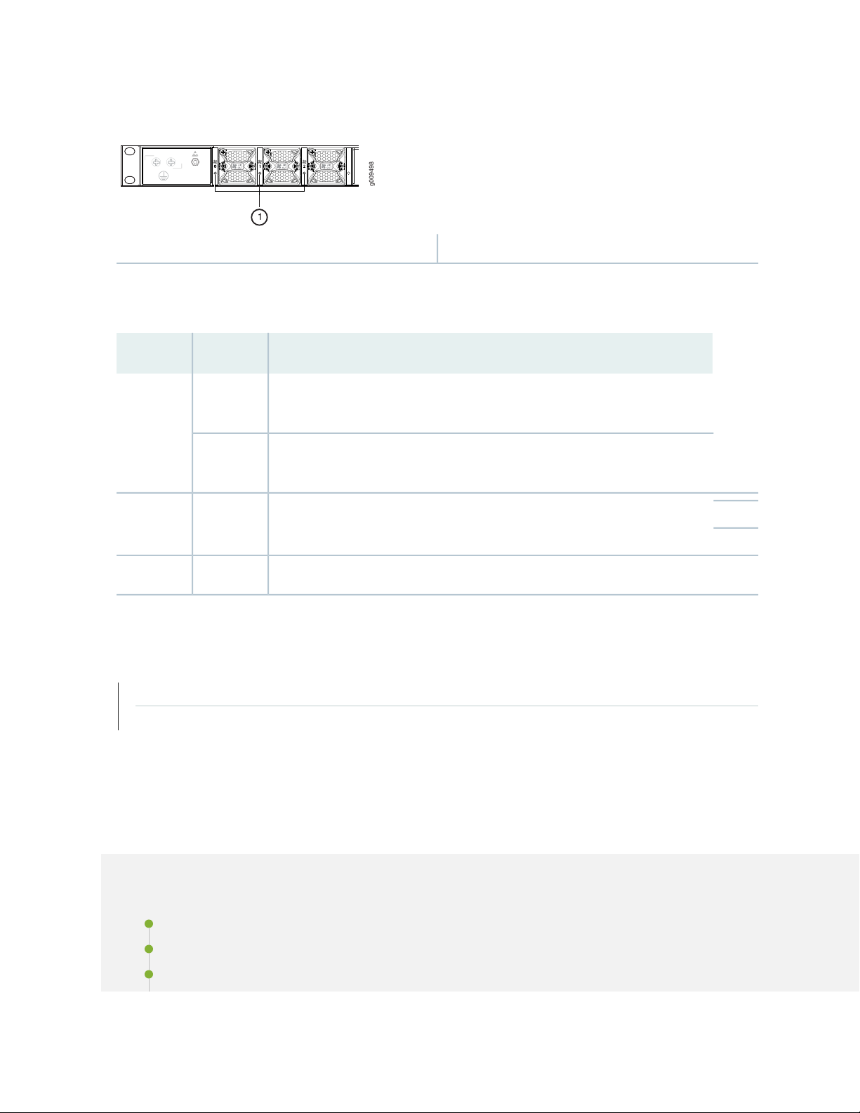
Figure 8: Fan Status LEDs on the Router
g009498
1
1—Fan status LEDs
The fan status LED is a bicolor LED. Table 8 on page 29 describes the behavior of the fan status LED.
Table 8: Fan Status LED
DescriptionStateColor
29
BlinkingGreen
steadily
Red
steadily
Fan module hardware initialization is complete and software initialization is
pending.
Software initialization is complete and the fan is functioning normally.On
Fan module is faulty and not functioning normally.On
Fan module not presentOff–
SEE ALSO
Replacing an MX204 Fan Module | 121
Maintaining the MX204 Fan Module | 120
MX204 AC Power System
IN THIS SECTION
MX204 Power System Description | 30
MX204 Power Supply Module LEDs | 32
MX204 Router AC Power Specifications | 35
Page 30
AC Power Circuit Breaker Requirements for the MX204 Router | 36
AC Power Cord Specifications for MX204 Routers | 37
MX204 Power System Description
IN THIS SECTION
AC Power Supply Description | 31
DC Power Supply Description | 31
30
The MX204 is powered using either AC or DC power. It supports two power supply modules (PSMs)
located at the rear of the chassis in slots 0 and 1. Figure 9 on page 31 and Figure 10 on page 32 show the
MX204 PSMs. The AC or DC power supply modules directly plug on to main board and are placed on the
right side of the rear chassis. Each power supply has a handle, an ejector lever, and status LEDs. The power
supply modules connect to the PSM board, which distributes the different output voltages produced by
the power supply modules to the router components, depending on their voltage requirements. When
both the power supply modules are present, they share power almost equally within a fully populated
system. If the first power supply in a redundant configuration fails or is removed, the second power supply
assumes the entire electrical load without interruption. A single power supply provides the maximum
configuration with full power for as long as the router is operational. A second power supply can be installed
for redundancy. The chassis is designed to support 1+1 feed redundancy.
Redundant power supply is hot-removable and hot-insertable. If you remove a power supply from a router
that uses only one power supply, then the router shuts down.
CAUTION: Do not mix AC and DC power supply modules in the same chassis.
NOTE: Routers configured with only one power supply are shipped with a blank panel installed
over the power supply slot that is not populated.
Page 31

The power supply modules are cooled by its own internal cooling system. A fan present in the power
g009867
supply module monitors and maintains the temperature inside.
AC Power Supply Description
Each AC power supply weighs approximately 2.2 lb (1 kg) and consists of a handle, an ejector lever, an AC
appliance inlet, a fan, and status LEDs to monitor the status of the power supply. Figure 9 on page 31
shows the AC power supply.
Each inlet requires a dedicated AC power feed and a dedicated customer-site circuit breaker. We recommend
that you use a minimum 20 A (110 VAC) or 16 A (220 VAC) customer-site circuit breaker, or as required
by local code.
WARNING: The router is pluggable type A equipment installed in a restricted-access
location. It has a separate protective earthing terminal (sized for 10–32 screws) provided
on the chassis in addition to the grounding pin of the power supply cord. This separate
protective earthing terminal must be permanently connected to earth.
31
Figure 9: AC Power Supply
DC Power Supply Description
Each DC power supply weighs approximately 2.2 lb (1 kg) and consists of a handle, an ejection lever, status
LEDs, and a terminal block that provides a single DC input (–48 VDC and return) that requires a dedicated
customer site circuit breaker. We recommend that you use a dedicated customer-site circuit breaker rated
for 25 A (–48 VDC) minimum, or as required by local code.
Figure 10 on page 32 shows the DC power supply.
Page 32

Figure 10: DC Power Supply
g009872
SEE ALSO
Maintaining the MX204 Power Supplies | 124
32
MX204 Power Supply Module LEDs
IN THIS SECTION
AC Power Supply Module LEDs | 32
DC Power Supply Module LEDs | 34
AC Power Supply Module LEDs
Figure 11 on page 33 shows the AC power supply module components along with the status LEDs.
Page 33

Figure 11: AC Power Supply Module LEDs and Components
g100048
1
2
3
4
5
g009866
1
2
3
5
4
4—1— Ejector leverInput status LED
5—2— AC power cord retainer portOutput status LED
3—Fault LED
Figure 12 on page 33 shows the AC power supply module components with the AC power cord retainer
along with the status LEDs.
33
Figure 12: AC Power Supply Module LEDs and Components––with the AC Power Cord Retainer
4—1— AC power cord retainer installedInput status LED
5—2— Ejector leverOutput status LED
3—Fault LED
Table 9 on page 33 describes the LEDs on the AC power supply modules.
Table 9: AC Power Supply Module LEDs
DescriptionStateColorLabel
OffUnlitAC OK
The power supply is disconnected from power source, or the
power supply is not receiving power.
Power supply is receiving power.On steadilyGreen
Page 34

Table 9: AC Power Supply Module LEDs (continued)
g009871
1 2 3
DescriptionStateColorLabel
Power supply output is off.OffUnlitDC OK
The power supply is sending out power correctly.On steadilyGreen
34
On steadilyAmber! (Fault)
An error has been detected in the power supply. Replace the
power supply as soon as possible. To maintain proper airflow
through the chassis, leave the power supply installed in the
chassis until you are ready to replace it.
NOTE: If the AC OK LED and the DC OK LED are unlit, either the AC power cord is not installed
properly or the power supply fuse has failed. If the AC OK LED is lit and the DC OK LED is unlit,
the AC power supply is installed properly, but the power supply has an internal failure.
DC Power Supply Module LEDs
Figure 13 on page 34 shows the DC power supply modules status LEDs.
Figure 13: DC Power Suppy Module LEDs
2—Output LED
3—1— Fault LEDInput LED
Page 35

CAUTION: On the DC power supply, the V+ terminals are shunted internally together,
as are the V– terminals. The same polarity terminal can be wired together from the
same source to provide an additional current path in a higher power chassis. Do not
connect the terminals to different sources.
Table 10 on page 35 describes the LEDs on the DC power supply modules.
Table 10: DC Power Supply Module LEDs
DescriptionStateColorLabel
35
SEE ALSO
OffUnlitIN (Input)
On steadilyGreen
On steadilyAmber! (Fault)
The power supply is disconnected from power
source, or the power supply is not receiving
power.
Power supply is receiving power.On steadilyGreen
Power supply output is off.OffUnlitOUT (Output)
The power supply is sending out power
correctly.
An error has been detected in the power
supply. Replace the power supply as soon as
possible. To maintain proper airflow through
the chassis, leave the power supply installed
in the chassis until you are ready to replace
it.
Routine Maintenance Procedures for MX204 Routers | 109
Maintaining the MX204 Power Supplies | 124
MX204 Router AC Power Specifications
Table 11 on page 36 lists the AC power system electrical specifications.
Page 36

Table 11: AC Power System Electrical Specifications
SpecificationItem
Operating range: 100 through 240 VACAC input voltage
50 through 60 Hz (nominal)AC input line frequency
36
AC system current rating
3.2 A @ 100 VAC
1.37 A @ 240 VAC
312 WAC system input power
Table 12 on page 36 lists the AC power supply electrical specifications.
Table 12: AC Power Supply Electrical Specifications
SpecificationItem
650 WMaximum output power
AC input voltage
Operating range:
100 through 127 VAC
200 through 240 VAC
50 to 60 Hz (nominal)AC input line frequency
AC input current rating
7.8 A @ 100 VAC
3.8 A @ 240 VAC
SEE ALSO
Maintaining the MX204 Power Supplies | 124
AC Power Circuit Breaker Requirements for the MX204 Router
We recommend that you use a dedicated customer-site circuit breaker rated for 20 A (110 VAC) minimum
or 16 A (220 VAC) minimum for each AC power feed, or as required by local code. Doing so enables you
to operate the router in any configuration without upgrading the power infrastructure.
Page 37

SEE ALSO
Replacing an MX204 AC Power Supply | 126
Power Consumption for an AC-Powered MX204 Router | 67
General Safety Guidelines and Warnings | 145
General Electrical Safety Guidelines and Warnings | 172
Prevention of Electrostatic Discharge Damage | 173
AC Power Cord Specifications for MX204 Routers
A detachable AC power cord is supplied with the AC power supply modules. The coupler is type C13 as
described by International Electrotechnical Commission (IEC) standard 60320. The plug end of the power
cord fits into the power source outlet that is standard for your geographical location.
37
CAUTION: The AC power cord provided with each power supply is intended for use
with that power supply only and not for any other use.
NOTE: In North America, AC power cords must not exceed 4.5 meters (approximately 14.75 feet)
in length, to comply with National Electrical Code (NEC) Sections 400-8 (NFPA 75, 5-2.2) and
210-52 and Canadian Electrical Code (CEC) Section 4-010(3). The cords supplied with the switch
are in compliance.
Table 13 on page 37 gives the AC power cord specifications for the countries and regions listed in the
table.
Table 13: AC Power Cord Specifications
Juniper Model NumberPlug StandardsElectrical SpecificationsCountry/Region
CBL-EX-PWR-C13-ARIRAM 2073 Type RA/3250 VAC, 10 A, 50 HzArgentina
250 VAC, 10 A, 50 HzAustralia
SAA/3
CBL-EX-PWR-C13-AUAS/NZZS 3112 Type
CBL-EX-PWR-C13-BRNBR 14136 Type BR/3250 VAC, 10 A, 50 HzBrazil
CBL-EX-PWR-C13-CHGB 1002-1996 Type PRC/3250 VAC, 10 A, 50 HzChina
Page 38

Table 13: AC Power Cord Specifications (continued)
Switzerland, and United
Kingdom)
38
Juniper Model NumberPlug StandardsElectrical SpecificationsCountry/Region
CBL-EX-PWR-C13-EUCEE (7) VII Type VIIG250 VAC, 10 A, 50 HzEurope (except Italy,
CBL-EX-PWR-C13-INIS 1293 Type IND/3250 VAC, 10 A, 50 HzIndia
CBL-EX-PWR-C13-ILSI 32/1971 Type IL/3G250 VAC, 10 A, 50 HzIsrael
CBL-EX-PWR-C13-ITCEI 23-16 Type I/3G250 VAC, 10 A, 50 HzItaly
Japan
Hz
Korea
Hz
250 VAC, 10 A, 50 HzSouth Africa
ZA/13
Taiwan
50 Hz
CBL-EX-PWR-C13-JPSS-00259 Type VCTF125 VAC, 12 A, 50 Hz or 60
CBL-EX-PWR-C13-KRCEE (7) VII Type VIIGK250 VAC, 10 A, 50 Hz or 60
CBL-EX-PWR-C13-USNEMA 5-15 Type N5-15125 VAC, 13 A, 60 HzNorth America
CBL-EX-PWR-C13-SASABS 164/1:1992 Type
CBL-EX-PWR-C13-SZSEV 6534-2 Type 12G250 VAC, 10 A, 50 HzSwitzerland
CBL-EX-PWR-C13-TWNEMA 5-15P Type N5-15P125 VAC, 11 A and 15 A,
CBL-EX-PWR-C13-UKBS 1363/A Type BS89/13250 VAC, 10 A, 50 HzUnited Kingdom
Figure 14 on page 38 illustrates the plug on the power cord for some of the countries or regions listed in
Table 13 on page 37.
Figure 14: AC Plug Types
SEE ALSO
Page 39

General Safety Guidelines and Warnings | 145
General Electrical Safety Guidelines and Warnings | 172
Prevention of Electrostatic Discharge Damage | 173
MX204 DC Power System
IN THIS SECTION
MX204 Router DC Power Specifications | 39
DC Power Circuit Breaker Requirements for the MX204 Router | 40
DC Power Source Cabling for MX204 Router | 41
DC Power Cable Specifications for MX204 Router | 42
39
MX204 Router DC Power Specifications
Table 14 on page 39 lists the DC power system electrical specifications.
Table 14: DC Power System Electrical Specifications
SpecificationItem
Operating range: –40 through –72 VDCDC input voltage
20 A @ –44 VDC (maximum)DC system input current
rating
DC system input power
Table 15 on page 39 lists the DC power supply electrical specifications.
Table 15: DC Power Supply Electrical Specifications
331 W
7.75 A @ –44 VDC
SpecificationItem
650 WMaximum output power
Page 40

Table 15: DC Power Supply Electrical Specifications (continued)
SpecificationItem
40
DC input voltage
Minimum: –40 VDC
Nominal: –48 VDC, –60 VDC
Operating range: –40 to –72 VDC
20 A @ –44 VDCDC input current rating
SEE ALSO
Maintaining the MX204 Power Supplies | 124
Replacing an MX204 DC Power Supply | 128
DC Power Circuit Breaker Requirements for the MX204 Router
Each DC power supply has a single DC input (–48 VDC and return) that requires a dedicated circuit breaker.
We recommend that you use a dedicated customer-site circuit breaker rated for 25 A (–48 VDC) minimum,
or as required by local code. Doing so enables you to operate the router in any configuration without
upgrading the power infrastructure.
If you plan to operate a DC-powered router at less than the maximum configuration and do not provision
a 25 A (–48 VDC) circuit breaker, we recommend that you provision a dedicated customer-site circuit
breaker for each DC power supply rated for at least 125 percent of the continuous current that the system
draws at –48 VDC.
SEE ALSO
Replacing an MX204 DC Power Supply | 128
Power Consumption for a DC-Powered MX204 Router | 69
General Safety Guidelines and Warnings | 145
General Electrical Safety Guidelines and Warnings | 172
Prevention of Electrostatic Discharge Damage | 173
Page 41

DC Power Source Cabling for MX204 Router
The DC power supply in PS0 must be powered by a dedicated power feed derived from feed A, and the
DC power supply in PS1 must be powered by a dedicated power feed derived from feed B. This configuration
provides the commonly deployed A/B feed redundancy for the system.
CAUTION: You must ensure that power connections maintain the proper polarity.
The power source cables might be labeled (+) and (–) to indicate their polarity. There
is no standard color coding for DC power cables. The color coding used by the external
DC power source at your site determines the color coding for the leads on the power
cables that attach to the terminal studs on each power supply.
WARNING: For field-wiring connections, use copper conductors only.
41
CAUTION: Power cords and cables must not block access to device components or
drape where people could trip on them.
SEE ALSO
Replacing an MX204 DC Power Supply | 128
Power Consumption for a DC-Powered MX204 Router | 69
General Safety Guidelines and Warnings | 145
General Electrical Safety Guidelines and Warnings | 172
Prevention of Electrostatic Discharge Damage | 173
Page 42

DC Power Cable Specifications for MX204 Router
g009544
.170 max
wire diameter
(insulation)
.84
.71
.25
.15 dia
All measurements in inches
IN THIS SECTION
DC Power Cable Lug Specifications | 42
DC Power Cable Specifications | 42
DC Power Cable Lug Specifications
The accessory box shipped with the router includes the cable lugs that attach to the terminal of each
power supply.
Figure 15: DC Power Cable Lug
42
CAUTION: Before router installation begins, a licensed electrician must attach a cable
lug to the grounding and power cables that you supply. A cable with an incorrectly
attached lug can damage the router.
DC Power Cable Specifications
You must supply four DC power cables that meet the following specifications: 14-16 AWG (2.08 - 1.3 mm2),
minimum 60° C wire, or as required by the local code.
SEE ALSO
Page 43

Replacing an MX204 DC Power Supply | 128
Power Consumption for a DC-Powered MX204 Router | 69
MX204 Host Subsystem
IN THIS SECTION
MX204 Routing Engine Description | 43
MX204 Routing Engine LEDs | 46
43
MX204 Routing Engine Description
IN THIS SECTION
Routing Engine Functions | 43
Routing Engine Components | 44
Routing Engine Front Panel | 44
Routing Engine Interface Ports | 45
The host subsystem provides routing protocol processes, as well as software processes that control the
router’s interface, the chassis components, system management, and user access to the router. These
routing processes run on top of a kernel that interacts with the Packet Forwarding Engine. The MX204
host subsystem consists of a single built-in Routing Engine.
This topic covers:
Routing Engine Functions
The Routing Engine is built-in on the MX204 baseboard and cannot be replaced. The Routing Engine
performs all route-processing functions, and provides performs chassis control and management plane
functionality. The Routing Engine also provides control plane functions.
Page 44

The Routing Engine supports the following functionalities to manage the operation of the router:
g009897
15
8
1016
732 4 6
9
1 5
1314 1112
System control functions such as environmental monitoring
•
Routing Layer 2 and Layer 3 protocols
•
Communication to components such as line cards, power supply, and cooling system
•
Transparent clocking
•
Alarm and logging functions
•
Routing Engine Components
The Routing Engine consists of the following internal components:
High-performance 1.6-GHz Intel 8 Core X86 CPU
•
32-GB DDR4 RAM
•
100-GB SATA SSD
•
44
Routing Engine Front Panel
Figure 16 on page 44 shows the front panel of the MX204 chassis.
Figure 16: MX204 Ports
9—1— RESET buttonRate-selectable ports
10—2— SSD0 LEDManagement (MGMT) port
11—3— Alarm (ALM) LEDBITS port with LEDs
12—4— OK/FAIL LEDUSB port
1PPS and 10MHz GPS input and output ports
13—5— Time of day (ToD) port with LEDs (This port is
reserved for future use)
14—6— Console (CON) portONLINE LED
15—7— 10-Gigabit Ethernet SFP+ portsSSD1 LED
16—8— PTP grandmaster clock (GM/PTP) portOFFLINE button
Page 45

Routing Engine Interface Ports
The ports located on the router connect the Routing Engine to one or more external devices on which
system administrators can issue Junos OS CLI commands to manage the router. In addition, ports to connect
external clock interfaces for BITS and GPS function are also available on the router.
The Routing Engine interface ports with the indicated labels function are as follows (see
Figure 16 on page 44):
CON—Connects the Routing Engine to a system console through a serial cable with an RJ-45 connector.
•
MGMT—Connects the Routing Engine through an Ethernet connection to a management LAN (or any
•
other device that plugs into an Ethernet connection) for out-of-band management. The port uses an
autosensing RJ-45 connector to support 10-Mbps, 100-Mbps, or 1000-Mbps connections. Two small
LEDs (an activity LED and a link LED) on the port indicate the connection in use.
The link LED is:
lit amber (steady) when the 1000-Mbps link is up.
•
45
lit green (steady) when the 100-Mbps link is up.
•
Off when the 10-Mbps link is up.
•
The activity LED is:
lit green (blinking) when traffic is passing through the port.
•
lit green (steady) when traffic is not passing through the port.
•
Both activity and link LEDs are off when the link is down.
BITS—Building-integrated timing supply (BITS) external clocking interface for connecting to external
•
clocking devices.
ToD—Time-of-day (TOD) port on the front panel of the router that enables you to connect external
•
timing signal sources.
NOTE: This port is reserved for future use.
10MHZ (one input and one output)—The 10-MHz timing connectors on the front panel of the router
•
that connect to external clock signal sources. The clocking ports provide the synchronized output clocks
from any one of the reference clock inputs based on the clock’s priority.
Page 46

PPS (one input and one output)—1-pulse-per-second (PPS) connectors on the front panel of the router
•
that connect to external clock signal sources. The clocking ports provide the synchronized output clocks
from any one of the reference clock inputs based on the clock’s priority.
USB—Provides a removable media interface through which you can install Junos OS manually. Junos
•
OS supports USB version 1.0 and later.
SEE ALSO
RJ-45 Connector Pinouts for MX Series CB-RE or RCB Auxillary and Console Ports | 65
RJ-45 Connector Pinouts for an MX Series CB-RE or RCB Management Port | 66
MX204 Chassis Description | 20
MX204 Routing Engine LEDs
46
The Routing Engine is built-in on the MX204 and is attached to the baseboard and cannot be replaced.
The status of the Routing Engine is displayed by the ONLINE and OK/FAIL LEDs on the front panel of
the MX204 chassis.
Table 16 on page 46 describes the functions and LEDs on the MX204 router.
NOTE: The functioning of the MX204 router is controlled by the Routing Engine, and the LEDs
present on the front panel of the router displays the status and functioning of the MX204 router.
Table 16: MX204 LEDs
DescriptionStateColorLabel
GreenONLINE
Red
On
steadily
steadily
Both Junos OS and Linux are successfully loaded
on the router.
Router is starting Junos OS.Blinking
Router has loaded Linux.On
Router is starting Linux.Blinking
Router is offline.Off–
Page 47

Table 16: MX204 LEDs (continued)
47
DescriptionStateColorLabel
GreenOK/FAIL
RedALM
Yellow
steadily
On
steadily
On
steadily
Router is functioning normally.On
Router has failed.BlinkingRed
Router is not powered on.Off–
Critical alarm—Indicates a critical condition that
can cause the router to stop functioning. Possible
causes include component failure, or any major
software failure.
Warning alarm—Indicates a serious but nonfatal
error condition, such as a maintenance alert or
a significant increase in component temperature.
There is no alarm.Off–
SSD0 is being accessed by the router.BlinkingGreenSSD0
SSD0 is not active or not being accessed.Off–
SSD1 is being accessed by the router.BlinkingGreenSSD1
SSD1 is not active or not being accessed.Off–
Page 48

Table 16: MX204 LEDs (continued)
48
DescriptionStateColorLabel
GreenBITS
–
Amber
–
When there is no loss (BITS is in locked state).On
Steadily
(Activity
LED; left)
When there is loss of signal or loss of line.Off
(Activity
LED; left)
When there is loss of signal or loss of line.On
steadily
(Link LED;
right)
When there is no loss (BITS is in locked state).Off
(Link LED;
right)
Page 49

2
CHAPTER
Site Planning, Preparation, and
Specifications
MX204 Site Preparation Checklist | 50
MX204 Site Guidelines and Requirements | 51
MX204 Network Cable and Transceiver Planning | 60
MX204 Management and Console Port Specifications and Pinouts | 65
MX204 Power Planning | 67
Page 50

MX204 Site Preparation Checklist
The checklist in Table 17 on page 50 summarizes the tasks you must perform when preparing a site for
router installation.
Table 17: MX204 Site Preparation Checklist
DatePerformed byFor More InformationItem or Task
Environment
50
Verify that environmental factors such as
temperature and humidity do not exceed
router tolerances.
Power
Locate sites for connection of system
grounding.
Measure distance between external power
sources and router installation site.
Calculate the power consumption and
requirements.
“MX204 Router Environmental
Specifications” on page 52
“MX204 Router Grounding
Specifications” on page 54
“MX204 Router DC Power
Specifications” on page 39
“MX204 Router AC Power
Specifications” on page 35
“Power Consumption for a
DC-Powered MX204 Router” on
page 69
“Power Consumption for an
AC-Powered MX204 Router” on
page 67
Rack
Select the type of rack or cabinet.
“MX204 Router Rack
Requirements” on page 58
“MX204 Router Cabinet
Requirements and Specifications”
on page 55
Page 51

Table 17: MX204 Site Preparation Checklist (continued)
51
DatePerformed byFor More InformationItem or Task
Plan rack or cabinet location, including
required space clearances.
If a rack is used, secure rack to floor and
building structure.
Cables
Acquire cables and connectors:
Determine the number of cables needed
•
based on your planned configuration.
Review the maximum distance allowed
•
for each cable. Choose the length of cable
based on the distance between the
hardware components being connected.
“MX204 Router Clearance
Requirements for Airflow and
Hardware Maintenance” on
page 57
“MX204 Router Rack
Requirements” on page 58
“Calculating Power Budget and
Power Margin for Fiber-Optic
Cables” on page 60
RELATED DOCUMENTATION
MX204 Installation Overview | 72
Tools Required to Install the MX204 Chassis in Rack | 77
Installing the MX204 Chassis in a Rack | 77
MX204 Site Guidelines and Requirements
IN THIS SECTION
MX204 Router Physical Specifications | 52
MX204 Router Environmental Specifications | 52
MX204 Router Grounding Specifications | 54
MX204 Router Cabinet Requirements and Specifications | 55
Page 52

MX204 Router Clearance Requirements for Airflow and Hardware Maintenance | 57
MX204 Router Rack Requirements | 58
MX204 Router Physical Specifications
Table 18 on page 52 summarizes the physical specifications for the router.
Table 18: Router Physical Specifications
52
HeightDepthWidthWeightDescription
Chassis fully loaded with
all FRUs
chassis: 22.7 lb
(10.3 kg)
SEE ALSO
MX204 Router Overview | 18
MX204 Chassis Description | 20
19 in. (48.26 cm)AC-powered
18.50 in. (47.0 cm)
20.43 in. (51.89 cm)
with fan and power
handles
1.72 in. (4.37 cm;
1 U)
1.64 in. (4.17 cm)5.78 in. (14.68 cm)1.89 in. (4.8 cm)1.5 lb (0.68 kg)Fan tray
1.58 in. (4.01 cm)14.50 in. (36.83 cm)2.23 in. (5.66 cm)2.2 lb (1 kg)AC power supply
1.67 in. (4.24 cm)14.53 in. (36.91 cm)2.23 in. (5.66 cm)2.2 lb (1 kg)DC power supply
MX204 Router Environmental Specifications
Table 19 on page 53 specifies the environmental specifications required for normal router operation. In
addition, the site should be as dust-free as possible.
Page 53

Table 19: Router Environmental Specifications
ValueDescription
No performance degradation up to 10,000 ft (3048 m)Altitude
53
Relative humidity
Temperature
Seismic
Normal operation ensured in relative humidity range of 5%
through 90%, noncondensing
Normal operation ensured in temperature range of 32°F (0°C)
•
through 104°F (40°C)
Short-term operation ensured in temperature range of 23°
•
F (–5° C) through 131° F (55° C).
NOTE: As defined in NEBS GR-63-CORE, Issue 4, short-term
events can be up to 96 hours in duration but not more than
15 days per year.
Nonoperating storage temperature in shipping container:
•
–40°F (–40°C) through 158°F (70°C)
Designed to meet Telcordia Technologies Zone 4 earthquake
requirements
1705 BTU/hour (500 W)Maximum thermal output
NOTE: Install the router only in restricted-access areas, such as dedicated equipment rooms
and equipment closets, in accordance with Articles 110-16, 110-17, and 110-18 of the National
Electrical Code, ANSI/NFPA 70.
SEE ALSO
Routine Maintenance Procedures for MX204 Routers | 109
General Safety Guidelines for Juniper Networks Devices
General Safety Warnings for Juniper Networks Devices | 146
Page 54

MX204 Router Grounding Specifications
Rear panel
g009882
1
Grounding Points Specifications
To meet safety and electromagnetic interference (EMI) requirements and to ensure proper operation, the
router must be adequately grounded before power is connected. To ground AC-powered and DC-powered
routers, you must connect a grounding cable to earth ground and then attach it to the chassis grounding
points by using the two screws provided.
Figure 17 on page 54 shows the grounding point location on the router.
A protective earthing terminal bracket is required for connecting the chassis to earth ground. This two-holed
bracket attaches on the side of the chassis through the mounting rail and provides a protective earthing
terminal for the router. The grounding points are studs sized for 10–32 screws. The 10–32 screws are
provided with the MX204 router. The grounding points are spaced at 0.75-in. (19.1-mm) centers.
Two threaded holes are provided on the rear left side of the chassis for connecting the router to earth
ground. The grounding points fit 10–32 screws.
54
NOTE: Additional grounding is provided to an AC-powered router when you plug its power
supply modules into grounded AC power receptacles.
Figure 17: Grounding Points on the Router
Grounding Cable Lug Specifications
You must provide one grounding cable lug that attaches to the grounding cable and 10–32 screws used
to secure the grounding cable to the grounding points.
CAUTION: Before router installation begins, a licensed electrician must attach a cable
lug to the grounding and power cables that you supply. A cable with an incorrectly
attached lug can damage the router.
Page 55

Grounding Cable Specifications
The grounding lug required is a Panduit LCD10-10A-L or equivalent (not provided). The grounding lug
accommodates 12 AWG (2.5 mm²) stranded wire. The grounding cable that you provide for the chassis
must be the same size or heavier than the input wire of each power supply module. Minimum
recommendations are 12 AWG (2.5 mm²) stranded wire, 60° C wire, or as permitted by local code.
SEE ALSO
Tools and Parts Required for MX204 Router Grounding and Power Connections | 84
Prevention of Electrostatic Discharge Damage | 173
MX204 Router AC Power Specifications | 35
MX204 Router DC Power Specifications | 39
55
MX204 Router Cabinet Requirements and Specifications
Table 20 on page 55 summarizes cabinet requirements and specifications for the MX204 router.
Table 20: Cabinet Requirements and Specifications for an MX204 Router
Guidelines for the MX204 RouterCabinet Requirement
Cabinet size and clearance
The minimum-sized cabinet that can accommodate the router is 19-in. (482-mm)
•
wide, and 23.62-in. (600-mm) deep. A cabinet larger than the minimum
requirement provides better airflow and reduces the chance of overheating. If
you provide adequate cooling air and airflow clearance, you can stack several
routers in a cabinet that has sufficient usable vertical space. Each router requires
1 U.
A U is the standard rack unit defined in Cabinets, Racks, Panels, and Associated
Equipment (document number EIA-310-D) published by the Electronic
Components Industry Association (ECIA) (http://www.ecianow.org).
With adequate cooling air and airflow clearance, you can stack multiple MX204
•
routers in a cabinet with a four-post rack. In all cases, the rack must meet the
strength requirements to support the weight.
The minimum total clearance inside the cabinet is 30.7 in. (780 mm) between
•
the inside of the front door and the inside of the rear door.
Page 56

Table 20: Cabinet Requirements and Specifications for an MX204 Router (continued)
Guidelines for the MX204 RouterCabinet Requirement
56
Cabinet airflow requirements
When you install the router in a cabinet, you must ensure that ventilation through
the cabinet is sufficient to prevent overheating. Consider the following
requirements to when planning for chassis cooling:
Airflow must always be from front to back with respect to the rack. If the device
•
has side to rear airflow, then provisions must be made to ensure that fresh air
from the front of the rack is supplied to the inlets, and exhaust exits from the
rear of the rack. The device must not interfere with the cooling of other systems
in the rack. Fillers must be used as appropriate in the rack to ensure there is
no recirculation of heated exhaust air back to the front of the rack. Care must
also be taken around cables to ensure no leakage of air in situations where
recirculation might result.
Ensure that the cabinet allows the chassis hot exhaust air to exit from the
•
cabinet without recirculating into the router. An open cabinet (without a top
or doors) that employs hot air exhaust extraction from the top allows the best
airflow through the chassis. If the cabinet contains a top or doors, perforations
in these elements assist with removing the hot air exhaust. For an illustration
of chassis airflow, see Figure 18 on page 57.
Ensure that the cool air supply you provide through the cabinet can adequately
•
dissipate the thermal output of the router.
Route and dress all cables to minimize the blockage of airflow to and from the
•
chassis.
Ensure that the spacing of rails and adjacent racks allows for the proper
•
clearance around the router and rack as specified in “MX204 Router Clearance
Requirements for Airflow and Hardware Maintenance” on page 57.
Install the router as close as possible to the front of the cabinet so that the
•
chassis just clears the inside of the front door. This maximizes the clearance in
the rear of the cabinet for critical airflow.
Page 57

Figure 18: Airflow Through MX204 Chassis
g009880
Ports
FRUs
57
SEE ALSO
MX204 Installation Overview | 72
MX204 Cooling System Description | 26
MX204 Router Clearance Requirements for Airflow and Hardware Maintenance
When planning the installation site, allow sufficient clearance around the rack (see Figure 19 on page 58):
For the cooling system to function properly, the airflow around the chassis must be unrestricted. Allow
•
at least 6 in. (15.2 cm) of clearance between side-cooled routers. Allow 2.8 in. (7 cm) between the side
of the chassis and any non-heat-producing surface such as a wall.
For service personnel to remove and install hardware components, there must be adequate space at the
•
front and back of the router. At least 24 in. (61 cm) are required both in front of and behind the router.
NEBS GR-63 recommends that you allow at least 30 in. (76.2 cm) in front of the rack and 24 in. (61 cm)
behind the router.
To accommodate power cable bend radius at the rear of the chassis and the interface cable bend radius
•
at the front of the chassis, provide at least 2.75 in. (7 cm) at the rear and 3.5 in. (8.9 cm) at the front.
Page 58

Figure 19: MX204 Chassis Dimensions and Clearance Requirements
58
MX204 Router Rack Requirements
The MX204 router can be installed in a standard 19-in. rack. Many types of racks are acceptable, including
four-post (telco) racks and open-frame racks. Table 21 on page 58 summarizes rack requirements and
specifications for the router.
Table 21: Rack Requirements and Specifications for an MX204 Router
GuidelinesRack Requirement
Rack type and mounting bracket
hole spacing
Use a four-post rack. You can mount the router on any four-post rack that
provides bracket holes or hole patterns spaced at 1 U (1.75-in./4.44-cm)
increments and that meets the size and strength requirements specified in this
table.
A U is the standard rack unit defined in Cabinets, Racks, Panels, and Associated
Equipment (document number EIA-310–D) published by the Electronics
Components Industry Association (http://www.ecianow.org/).
Page 59

Table 21: Rack Requirements and Specifications for an MX204 Router (continued)
GuidelinesRack Requirement
59
Rack size and strength
Ensure that the rack is a 19-in. rack as defined in Cabinets, Racks, Panels, and
•
Associated Equipment (document number EIA-310–D) published by the
Electronics Components Industry Association (http://www.ecianow.org/).
Ensure that the rack is one of the following standard lengths:
•
23.6 in. (600 mm)
•
30.0 in. (762 mm)
•
31.5 in. (800 mm)
•
The rack rails must be spaced widely enough to accommodate the router
•
chassis's external dimensions (see “MX204 Router Physical Specifications”
on page 52). The outer edges of the mounting brackets extend the width to
19 in. (48.3 cm). The spacing of rails and adjacent racks must also allow for
the clearances around the router and rack.
The router ships with the front-mounting brackets fixed in the front-mount
•
position on the chassis. You can move the rear-mounting brackets based on
the depth of the rack.
The chassis height of 1.72 in. (4.37 cm) is approximately 1 U (rack unit).
•
The rack must be strong enough to support the weight of the fully configured
•
router, up to 22.7 lb (10.3 kg).
Either end of the router must be mounted flush with the rack and still be
•
adjustable for racks with different depths. The front and rear rack rails must
be spaced between 23.62 in. (600 mm) and 31.5 in. (800 mm) front to back.
Ensure that the spacing of rails and adjacent racks allows for the proper
•
clearance around the router and rack.
Rack connection to the building
structure
SEE ALSO
MX204 Installation Overview | 72
Secure the rack to the building structure.
•
If earthquakes are a possibility in your geographic area, secure the rack to
•
the floor.
Secure the rack to the ceiling brackets as well as wall or floor brackets for
•
maximum stability.
Page 60

MX204 Network Cable and Transceiver Planning
IN THIS SECTION
Calculating Power Budget and Power Margin for Fiber-Optic Cables | 60
CB-RE and RCB Interface Cable and Wire Specifications for MX Series Routers | 62
Fiber-Optic Cable Signal Loss, Attenuation, and Dispersion | 63
Calculating Power Budget and Power Margin for Fiber-Optic Cables
Use the information in this topic and the specifications for your optical interface to calculate the power
budget and power margin for fiber-optic cables.
60
TIP: You can use the Hardware Compatibility Tool to find information about the pluggable
transceivers supported on your Juniper Networks device.
To calculate the power budget and power margin, perform the following tasks:
1.
How to Calculate Power Budget for Fiber-Optic Cable | 60
2.
How to Calculate Power Margin for Fiber-Optic Cable | 61
How to Calculate Power Budget for Fiber-Optic Cable
To ensure that fiber-optic connections have sufficient power for correct operation, you need to calculate
the link's power budget, which is the maximum amount of power it can transmit. When you calculate the
power budget, you use a worst-case analysis to provide a margin of error, even though all the parts of an
actual system do not operate at the worst-case levels. To calculate the worst-case estimate of power
budget (PB), you assume minimum transmitter power (PT) and minimum receiver sensitivity (PR):
PB= PT– P
The following hypothetical power budget equation uses values measured in decibels (dB) and decibels
referred to one milliwatt (dBm):
R
PB= PT– P
R
Page 61

PB= –15 dBm – (–28 dBm)
PB= 13 dB
How to Calculate Power Margin for Fiber-Optic Cable
After calculating a link's power budget, you can calculate the power margin (PM), which represents the
amount of power available after subtracting attenuation or link loss (LL) from the power budget (PB). A
worst-case estimate of PMassumes maximum LL:
PM= PB– LL
PMgreater than zero indicates that the power budget is sufficient to operate the receiver.
Factors that can cause link loss include higher-order mode losses, modal and chromatic dispersion,
connectors, splices, and fiber attenuation. Table 22 on page 61 lists an estimated amount of loss for the
factors used in the following sample calculations. For information about the actual amount of signal loss
caused by equipment and other factors, refer to vendor documentation.
61
Table 22: Estimated Values for Factors Causing Link Loss
Estimated Link-Loss ValueLink-Loss Factor
Higher-order mode losses
Modal and chromatic dispersion
Fiber attenuation
Single mode—None
Multimode—0.5 dB
Single mode—None
Multimode—None, if product of bandwidth and distance is less than
500 MHz-km
0.5 dBConnector
0.5 dBSplice
Single mode—0.5 dB/km
Multimode—1 dB/km
The following sample calculation for a 2-km-long multimode link with a power budget (PB) of 13 dB uses
the estimated values from Table 22 on page 61 to calculate link loss (LL) as the sum of fiber attenuation
(2 km @ 1 dB/km, or 2 dB) and loss for five connectors (0.5 dB per connector, or 2.5 dB) and two splices
(0.5 dB per splice, or 1 dB) as well as higher-order mode losses (0.5 dB). The power margin (PM) is calculated
as follows:
PM= PB– LL
Page 62

PM= 13 dB – 2 km (1 dB/km) – 5 (0.5 dB) – 2 (0.5 dB) – 0.5 dB
PM= 13 dB – 2 dB – 2.5 dB – 1 dB – 0.5 dB
PM= 7 dB
The following sample calculation for an 8-km-long single-mode link with a power budget (PB) of 13 dB
uses the estimated values from Table 22 on page 61 to calculate link loss (LL) as the sum of fiber attenuation
(8 km @ 0.5 dB/km, or 4 dB) and loss for seven connectors (0.5 dB per connector, or 3.5 dB). The power
margin (PM) is calculated as follows:
PM= PB– LL
PM= 13 dB – 8 km (0.5 dB/km) – 7(0.5 dB)
PM= 13 dB – 4 dB – 3.5 dB
PM= 5.5 dB
In both examples, the calculated power margin is greater than zero, indicating that the link has sufficient
power for transmission and does not exceed the maximum receiver input power.
62
CB-RE and RCB Interface Cable and Wire Specifications for MX Series Routers
Table 23 on page 62 lists the specifications for the cables that connect to management ports and the wires
that connect to the alarm relay contacts.
NOTE: In routers where the Routing Engine (RE) and Control Board (CB) are integrated into a
single board, a CB-RE is known as Routing and Control Board (RCB). The RCB is a single FRU
that provides RE and CB functionality.
Table 23: Cable and Wire Specifications for Routing Engine and RCB Management and Alarm Interfaces
Router
Receptacle
RJ-45 socket1.83 m1.83-m length
Routing Engine
console or
auxiliary
interface
Cable
SpecificationPort
RS-232
(EIA-232) serial
cable
Cable/Wire
Supplied
with
RJ-45/DB-9
connectors
Maximum
Length
Page 63

Table 23: Cable and Wire Specifications for Routing Engine and RCB Management and Alarm
Interfaces (continued)
63
Router
Receptacle
RJ-45
autosensing
—NoneNoWire with
Routing Engine
Ethernet
interface
Alarm relay
contacts
Cable
SpecificationPort
Category 5
cable or
equivalent
suitable for
100Base-T
operation
gauge between
28-AWG and
14-AWG (0.08
and 2.08 mm2)
Cable/Wire
Supplied
length with
RJ-45/RJ-45
connectors
Maximum
Length
100 mOne 4.57-m
Fiber-Optic Cable Signal Loss, Attenuation, and Dispersion
IN THIS SECTION
Signal Loss in Multimode and Single-Mode Fiber-Optic Cable | 63
Attenuation and Dispersion in Fiber-Optic Cable | 64
Signal Loss in Multimode and Single-Mode Fiber-Optic Cable
Multimode fiber is large enough in diameter to allow rays of light to reflect internally (bounce off the walls
of the fiber). Interfaces with multimode optics typically use LEDs as light sources. However, LEDs are not
coherent sources. They spray varying wavelengths of light into the multimode fiber, which reflects the
light at different angles. Light rays travel in jagged lines through a multimode fiber, causing signal dispersion.
When light traveling in the fiber core radiates into the fiber cladding, higher-order mode loss results.
Together these factors limit the transmission distance of multimode fiber compared with single-mode
fiber.
Single-mode fiber is so small in diameter that rays of light can reflect internally through one layer only.
Interfaces with single-mode optics use lasers as light sources. Lasers generate a single wavelength of light,
Page 64

which travels in a straight line through the single-mode fiber. Compared with multimode fiber, single-mode
fiber has higher bandwidth and can carry signals for longer distances.
Exceeding the maximum transmission distances can result in significant signal loss, which causes unreliable
transmission.
Attenuation and Dispersion in Fiber-Optic Cable
Correct functioning of an optical data link depends on modulated light reaching the receiver with enough
power to be demodulated correctly. Attenuation is the reduction in power of the light signal as it is
transmitted. Attenuation is caused by passive media components, such as cables, cable splices, and
connectors. Although attenuation is significantly lower for optical fiber than for other media, it still occurs
in both multimode and single-mode transmission. An efficient optical data link must have enough light
available to overcome attenuation.
Dispersion is the spreading of the signal over time. The following two types of dispersion can affect an
optical data link:
64
Chromatic dispersion—Spreading of the signal over time resulting from the different speeds of light rays.
•
Modal dispersion—Spreading of the signal over time resulting from the different propagation modes in
•
the fiber.
For multimode transmission, modal dispersion, rather than chromatic dispersion or attenuation, usually
limits the maximum bit rate and link length. For single-mode transmission, modal dispersion is not a factor.
However, at higher bit rates and over longer distances, chromatic dispersion rather than modal dispersion
limits maximum link length.
An efficient optical data link must have enough light to exceed the minimum power that the receiver
requires to operate within its specifications. In addition, the total dispersion must be less than the limits
specified for the type of link in Telcordia Technologies document GR-253-CORE (Section 4.3) and
International Telecommunications Union (ITU) document G.957.
When chromatic dispersion is at the maximum allowed, its effect can be considered as a power penalty in
the power budget. The optical power budget must allow for the sum of component attenuation, power
penalties (including those from dispersion), and a safety margin for unexpected losses.
Page 65

MX204 Management and Console Port Specifications and Pinouts
IN THIS SECTION
RJ-45 Connector Pinouts for MX Series CB-RE or RCB Auxillary and Console Ports | 65
RJ-45 Connector Pinouts for an MX Series CB-RE or RCB Management Port | 66
RJ-45 Connector Pinouts for MX Series CB-RE or RCB Auxillary and Console Ports
65
The ports–labeled—AUX and CONSOLE—on the Control Board and Routing Engine (CB-RE) or the Routing
and Control Board (RCB) are asynchronous serial interfaces that accept an RJ-45 connector. The ports
connect the Routing Engine to an auxiliary or console management device. Table 24 on page 65 describes
the RJ-45 connector pinout.
NOTE: In routers where the Routing Engine and Control Board (CB) are integrated into a single
board, a CB-RE is known as Routing and Control Board (RCB). The RCB is a single FRU that
provides Routing Engine and CB functionality.
Table 24: RJ-45 Connector Pinout for the AUX and CONSOLE Ports
DescriptionSignalPin
Request to SendRTS1
Data Terminal ReadyDTR2
Transmit DataTXD3
Signal GroundGround4
Signal GroundGround5
Receive DataRXD6
Page 66

Table 24: RJ-45 Connector Pinout for the AUX and CONSOLE Ports (continued)
DescriptionSignalPin
Data Set ReadyDSR/DCD7
Clear to SendCTS8
RJ-45 Connector Pinouts for an MX Series CB-RE or RCB Management Port
The port on the Control Board and Routing Engine (CB-RE; Routing and Control Board (RCB)) labeled
MGMT is an autosensing 10/100/1000-Mbps Ethernet RJ-45 receptacle that accepts an Ethernet cable
for connecting the Routing Engine to a management LAN (or other device that supports out-of-band
management).
66
NOTE: In routers where the Routing Engine and Control Board (CB) are integrated into a single
board, a CB-RE is known as Routing and Control Board (RCB). The RCB is a single FRU that
provides Routing Engine and CB functionality.
Table 25 on page 66 describes the RJ-45 connector pinout.
Table 25: RJ-45 Management Port Connector Pinouts for the CB-RE or RCB MGMT Port
DescriptionSignalPin
Transmit/receive data pair 1TRP1+1
Transmit/receive data pair 1TRP1–2
Transmit/receive data pair 2TRP2+3
Transmit/receive data pair 3TRP3+4
Transmit/receive data pair 3TRP3–5
Transmit/receive data pair 2TRP2–6
Transmit/receive data pair 4TRP4+7
Page 67

Table 25: RJ-45 Management Port Connector Pinouts for the CB-RE or RCB MGMT Port (continued)
DescriptionSignalPin
Transmit/receive data pair 4TRP4–8
MX204 Power Planning
IN THIS SECTION
Power Consumption for an AC-Powered MX204 Router | 67
Power Consumption for a DC-Powered MX204 Router | 69
67
Power Consumption for an AC-Powered MX204 Router
Use the information in this topic to determine the power consumption for your router and plan the amount
of power you need to provide to the router.
Power Requirements for MX204 Components on page 67
•
Calculating System Thermal Output on page 68
•
Power Requirements for MX204 Components
Table 26 on page 67 lists the power requirements for various hardware components when the router is
operating under typical and maximum voltage conditions.
Table 26: Power Requirements for MX204 Components
Power
Requirement at
25° C (Watts;
Typical)Component
Power Requirement
at 55° C (Watts;
Maximum)
280 W240 WFully loaded MX204 router
Page 68

Table 27 on page 68 lists the power requirements for the fully configured AC-powered routers operating
under typical voltage conditions.
Table 27: MX204 Router AC Router Power Requirements at Typical Temperature (25° C)
Power Requirement
Power Requirement at 25°
C (Watts)Chassis Configuration
(Watts) with 90%
Efficiency
266 W240 WFully configured chassis running at high activity
Table 28 on page 68 lists the power requirements for the fully configured AC-powered routers operating
under maximum voltage conditions.
Table 28: MX204 Router AC Router Power Requirements at Maximum Temperature (55° C)
Power Requirement
Power Requirement at 55°
C (Watts)Chassis Configuration
(Watts) with 90%
Efficiency
68
311 W280 WFully configured chassis running at high activity
Calculating System Thermal Output
After you have calculated the power consumption for your configuration, you can use that information to
determine the system thermal output (BTUs per hour). To do so, multiply the power consumption in watts
by 3.41.
For example, in Table 27 on page 68 we calculated the power consumption for a fully configured chassis
running at high activity at 25° C typical temperature to be 240 W. Using that information we can calculate
the system thermal output for the configuration:
Power consumption in watts * 3.41 = system thermal output in BTU/hr
240 W * 3.41 = 818.4 BTU/hr
SEE ALSO
MX204 Power System Description | 30
Replacing an MX204 AC Power Supply | 126
AC Power Cord Specifications for MX204 Routers | 37
AC Power Circuit Breaker Requirements for the MX204 Router | 36
Page 69

General Safety Guidelines and Warnings | 145
General Electrical Safety Guidelines and Warnings | 172
Prevention of Electrostatic Discharge Damage | 173
Power Consumption for a DC-Powered MX204 Router
Use the information in this topic to determine the power consumption for your router and plan the amount
of power you need to provide to the router.
Power Requirements for MX204 Components on page 69
•
Calculating System Thermal Output on page 70
•
Power Requirements for MX204 Components
69
Table 29 on page 69 lists the power requirements for various hardware components when the router is
operating under typical and maximum voltage conditions.
Table 29: Power Requirements for MX204 Components
Power
Requirement at
25° C (Watts;
Typical)Component
Table 30 on page 69 lists the power requirements for the fully configured DC-powered routers operating
under typical voltage conditions.
Table 30: MX204 Router DC Router Power Requirements at Typical Temperature (25° C)
Power Requirement at 25°
C (Watts)Chassis Configuration
Power Requirement
at 55° C (Watts;
Maximum)
280 W240 WFully loaded MX204 router
Power Requirement
(Watts) with 90%
Efficiency
266 W240 WFully configured chassis running at high activity
Table 31 on page 70 lists the power requirements for the fully configured DC-powered routers operating
under maximum voltage conditions.
Page 70

Table 31: MX204 Router DC Router Power Requirements at Maximum Temperature (55° C)
Power Requirement
Power Requirement at 55°
C (Watts)Chassis Configuration
(Watts) with 90%
Efficiency
311 W280 WFully configured chassis running at high activity
Calculating System Thermal Output
After you have calculated the power consumption for your configuration, you can use that information to
determine the system thermal output (BTUs per hour). To do so, multiply the power consumption in watts
by 3.41.
For example, in Table 30 on page 69 we calculated the power consumption for a fully configured chassis
running at high activity at 25° C typical temperature to be 240 W. Using that information we can calculate
the system thermal output for the configuration:
70
Power consumption in watts * 3.41 = system thermal output in BTU/hr
240 W * 3.41 = 818.4 BTU/hr
SEE ALSO
MX204 Power System Description | 30
Replacing an MX204 DC Power Supply | 128
DC Power Circuit Breaker Requirements for the MX204 Router | 40
DC Power Source Cabling for MX204 Router | 41
DC Power Cable Specifications for MX204 Router | 42
General Safety Guidelines and Warnings | 145
General Electrical Safety Guidelines and Warnings | 172
Prevention of Electrostatic Discharge Damage | 173
Page 71

3
CHAPTER
Initial Installation and Configuration
MX204 Installation Overview | 72
Unpacking the MX204 | 73
Installing the MX204 | 76
Connecting the MX204 to Power | 84
Connecting the MX204 to the Network | 96
Performing the Initial Software Configuration for the MX204 Router | 103
Page 72

MX204 Installation Overview
To install the router:
1. Prepare your installation site.
See “MX204 Site Preparation Checklist” on page 50.
2. Review the safety guidelines and warnings:
See “General Safety Guidelines and Warnings” on page 145.
•
See “General Safety Warnings for Juniper Networks Devices” on page 146.
•
3. Unpack the router and verify the parts:
a. See “Unpacking MX204 Router” on page 74.
b. See “Verifying the MX204 Router Parts Received” on page 75.
72
4. (Optional) Remove components from the MX204 router chassis before Installing It in a rack.
See individual topics listed in Removing, Installing, and Upgrading Components for removing components.
5. Install the router in the rack.
See “Installing the MX204 Chassis in a Rack” on page 77.
6. (Optional; Required only if you have removed the components from the router in step 4) Reinstall
components in the MX204 router after installing the chassis in a rack.
See individual topics listed in Removing, Installing, and Upgrading Components for installing components.
7. Connect cables to the network and external devices.
See “Connecting the MX204 Router to External Devices and Cables” on page 96.
8. Connect the grounding cable.
See “Grounding the MX204 Router” on page 85.
9. Connect the AC power cord or DC power cables:
See “Connecting Power to an AC-Powered MX204 Router” on page 86.
•
See “Connecting Power to a DC-Powered MX204 Router” on page 90.
•
10. Power on the router:
Page 73

See “Powering On an AC-Powered MX204 Router” on page 89.
•
See “Powering On a DC-Powered MX204 Router” on page 93.
•
11. Perform the initial system configuration.
See “Performing the Initial Software Configuration for the MX204 Router” on page 103.
RELATED DOCUMENTATION
MX204 Router Rack Requirements | 58
MX204 Router Clearance Requirements for Airflow and Hardware Maintenance | 57
MX204 Router Cabinet Requirements and Specifications | 55
Unpacking the MX204
73
IN THIS SECTION
Tools and Parts Required to Unpack the MX204 Router | 73
Unpacking MX204 Router | 74
Verifying the MX204 Router Parts Received | 75
Tools and Parts Required to Unpack the MX204 Router
To unpack the router and prepare for installation, you need the following tools:
Phillips (+) screwdriver, number 2
•
1/2-in. or 13-mm open-end or socket wrench to remove bracket bolts from the shipping pallet
•
SEE ALSO
MX204 Chassis Description | 20
MX204 Field-Replaceable Units | 23
Page 74

Unpacking MX204 Router | 74
Unpacking MX204 Router
The router is shipped in a cardboard carton and secured with foam packing material. The carton also
contains an accessory box and quick start instructions.
NOTE: The router is maximally protected inside the shipping carton. Do not unpack it until you
are ready to begin installation.
To unpack the router:
1. Move the shipping carton to a staging area as close to the installation site as possible, but where you
have enough room to remove the router.
74
2. Position the carton so that the arrows are pointing up.
3. Open the top flaps on the shipping carton.
4. Remove the accessory box, and verify the contents against the parts inventory on the label attached
to the carton.
5. Pull out the packing material holding the router in place.
6. Verify the contents of the carton against the packing list included with the router.
7. Save the shipping carton and packing materials in case you later need to move or ship the router.
SEE ALSO
MX204 Site Preparation Checklist | 50
Page 75

Verifying the MX204 Router Parts Received
A packing list is included in each shipment. Check the parts in the shipment against the items on the packing
list. The packing list specifies the part numbers and descriptions of each part in your order.
If any part is missing, contact a customer service representative.
A fully configured router contains the router chassis with installed components, listed in Table 32 on page 75,
and an accessory box, which contains the parts listed in Table 33 on page 75. The parts shipped with your
router can vary depending on the configuration you ordered.
Table 32: Parts List for a Fully Configured Router
QuantityComponent
1Chassis
2AC or DC power supply
75
Blank panels for slots without components installed
Table 33: Accessory Box Parts List
#6 screw
3Fan module
1Documentation Roadmap and Product Warranty
One blank panel for each slot not
occupied by a component
2Rack mount kit
16Philips M4x7mm flat head screws
QuantityPart
16Screws to mount chassis
2Screws to secure the ground cable lug
8DC power ring terminal lugs, 14 - 16 AWG, sized for
1Label, “Small Parts Enclosed”
1Label, “Accessories Contents”
Page 76

Table 33: Accessory Box Parts List (continued)
76
QuantityPart
1USB flash drive with Junos OS
1Read me first document
1Affidavit for T1 connection
1Juniper Networks Product Warranty
1End User License Agreement
1Document sleeve
23 in. x 5 in. pink bag
SEE ALSO
MX204 Site Preparation Checklist | 50
Installing the MX204
29 in. x 12 in. pink bag, ESD
1Accessory box, 19 in. x 12 in. x 3 in.
1Ethernet cable, RJ-45 to DB-9
1ESD wrist strap with cable
4ETSI brackets
IN THIS SECTION
Tools Required to Install the MX204 Chassis in Rack | 77
Installing the MX204 Chassis in a Rack | 77
Page 77

Tools Required to Install the MX204 Chassis in Rack
To install the router, you need the following tools and parts:
Phillips (+) screwdriver, number 2
•
ESD grounding wrist strap
•
Blank panels to cover any slots not occupied by a component
•
Mounting brackets, supplied with the router
•
Sixteen screws for securing the mounting brackets to the chassis, supplied with therouter
•
Four mounting screws, supplied with the router
•
SEE ALSO
77
MX204 Site Preparation Checklist | 50
Installing the MX204 Chassis in a Rack
IN THIS SECTION
Installing the MX204 Chassis in a 19-in. Rack | 78
Installing the MX204 in a 21-in. ETSI Rack | 80
Page 78

CAUTION:
g100049
If you are installing more than one router in a rack, install the lowest one first.
•
Installing a router in an upper position in a rack or cabinet requires a lift.
Before front-mounting the router in a rack, have a qualified technician verify that
•
the rack is strong enough to support the router's weight and is adequately supported
at the installation site.
Lifting the chassis and mounting it in a rack requires two people (one person to hold
•
the router in place and a second person to install the screws). The fully loaded chassis
weighs approximately 22.7 lb (10.3 kg).
The MX204 router is designed for installation in a rack that complies with either of the following standards:
19-in. rack—A 19-in. (450 mm) rack as defined in Cabinets, Racks, Panels, and Associated Equipment
•
(document number EIA-310-D) published by the Electronics Industry Association
(http://www.ecianow.org/).
78
ETSI rack—A 21-in. (500 mm) ETSI rack as defined in the European Telecommunications Standards
•
Institute (ETS 300 119) published by the European Telecommunications Standards Institute (ETSI).
Based on the rack, follow the steps mentioned on the below topics to install the router:
Installing the MX204 Chassis in a 19-in. Rack
To install the router in a 19-in. rack or cabinet:
1. Position the router in front of the rack or cabinet.
2. Attach an electrostatic discharge (ESD) grounding strap to your bare wrist and to a site ESD point.
3. Align the holes in the front mounting brackets with the holes on the side of the chassis (see
Figure 20 on page 78).
Figure 20: Attaching the Mounting Brackets
Page 79

4. Using a Phillips (+) number 2 screwdriver, secure the mounting brackets to the router using the mounting
g009889
g009890
screws.
5. With one person on each side, hold on to the bottom of the chassis and carefully lift it so that the
mounting brackets contact the rack rails.
6. Carefully slide the router onto the mounting brackets until the front-mounting brackets attached to
the chassis contact the rack rails (see Figure 21 on page 79).
Figure 21: Installing the Router in a Four-Post Rack
79
7. Install mounting screws into each of the open front-mounting holes aligned with the rack, starting from
the bottom, and secure them tightly. Figure 22 on page 79 shows the router fully secured to the front
rails of the four-post rack.
Figure 22: Router Secured by Front-Mounting Brackets
8. On the rear of the chassis, slide the rear-mounting brackets on either side of the chassis until the
rear-mounting brackets contact the rack rails (see Figure 23 on page 80).
The rear-mounting brackets on each side of the chassis are movable. You can adjust the brackets
according to the depth of the rack.
Page 80

Figure 23: Installing the Rear-Mounting Brackets
g009891
g009892
9. Install mounting screws into each of the open rear-mounting holes aligned with the rack, starting from
the bottom, and secure them tightly.
10. Visually inspect the alignment of the chassis. If the chassis is installed properly in the rack, all the
mounting screws on one side of the rack are aligned with the mounting screws on the opposite side
and the router is level. Figure 24 on page 80 shows the router fully secured and installed in a four-post
rack.
80
Figure 24: Router Installed in the Rack
Installing the MX204 in a 21-in. ETSI Rack
The ETSI racks are little wider than the standard 19-in. rack. To install the router in an ETSI rack, you need
to install the ETSI brackets on to the router. Figure 25 on page 81 shows the ETSI brackets supported by
MX204 router.
Page 81

Figure 25: ETSI Brackets
g009499
g100049
g0 0 9886
To install the router in a 21-in. ETSI rack or cabinet:
1. Position the router in front of the rack or cabinet.
2. Attach an electrostatic discharge (ESD) grounding strap to your bare wrist and to a site ESD point.
3. Align the holes in the front mounting brackets with the holes on the side of the chassis (see
Figure 26 on page 81).
Figure 26: Attaching the Mounting Brackets
81
4. Install the two front ETSI brackets on the front-mounting brackets on each side of the chassis (see
Figure 27 on page 81).
Figure 27: Installing the Front ETSI Brackets
5. With one person on each side, hold on to the bottom of the chassis and carefully lift it so that the
mounting brackets contact the rack rails.
6. Carefully slide the router onto the mounting brackets until the front-mounting brackets attached to
the chassis contact the rack rails (see Figure 28 on page 82).
Page 82

Figure 28: Installing the Router in a Four-Post Rack
g009545
g009546
g009898
7. Install mounting screws into each of the open front-mounting holes aligned with the rack, starting from
the bottom, and secure them tightly. Figure 29 on page 82 shows the router fully secured to the front
rails of the four-post rack.
Figure 29: Router Secured by Front-Mounting Brackets with ETSI Brackets
82
8. Install the two rear ETSI brackets on the rear-mounting brackets (see Figure 30 on page 82).
The rear-mounting brackets on each side of the chassis are movable. You can adjust the brackets
according to the depth of the rack.
Figure 30: Installing the Rear ETSI Brackets
9. On the rear of the chassis, slide the rear-mounting brackets (with the ETSI brackets installed) on either
side of the chassis until the rear-mounting brackets contact the rack rails (see Figure 31 on page 83).
Page 83

Figure 31: Installing the Rear-Mounting Brackets with ETSI Brackets
g009899
g009885
10. Install mounting screws into each of the open rear-mounting holes aligned with the rack, starting from
the bottom, and secure them tightly.
11. Visually inspect the alignment of the chassis. If the chassis is installed properly in the rack, all the
mounting screws on one side of the rack are aligned with the mounting screws on the opposite side
and the router is level. Figure 32 on page 83 shows the router fully secured and installed in a four-post
rack with ETSI brackets.
83
Figure 32: Router Installed in the Rack with ETSI Brackets
SEE ALSO
MX204 Site Preparation Checklist | 50
MX204 Router Grounding Specifications | 54
MX204 Router Clearance Requirements for Airflow and Hardware Maintenance | 57
Page 84

Connecting the MX204 to Power
IN THIS SECTION
Tools and Parts Required for MX204 Router Grounding and Power Connections | 84
Grounding the MX204 Router | 85
Connecting Power to an AC-Powered MX204 Router | 86
Powering On an AC-Powered MX204 Router | 89
Connecting Power to a DC-Powered MX204 Router | 90
Powering On a DC-Powered MX204 Router | 93
Powering Off the MX204 Router | 94
84
Tools and Parts Required for MX204 Router Grounding and Power Connections
To ground and provide power to the router, you need the following tools and parts:
Phillips (+) screwdrivers, numbers 1 and 2
•
Socket nut driver
•
2.5-mm flat-blade (–) screwdriver
•
Torque-controlled driver, with a maximum torque capacity of 6 lb-in. (0.7 Nm), for tightening screws to
•
terminals on each power supply on a DC-powered router
CAUTION: The maximum torque rating of the terminal screws on the DC power
supply is 6 lb-in. (0.7 Nm). The terminal screws might be damaged if excessive torque
is applied. Use only a torque-controlled driver to tighten screws on the DC power
supply terminals. Use an appropriately sized driver, with a maximum torque capacity
of 6 lb-in. or less. Ensure that the driver is undamaged and properly calibrated and
that you have been trained in its use. You might want to use a driver that is designed
to prevent overtorque when the preset torque level is achieved.
Wire cutters
•
Electrostatic discharge (ESD) grounding wrist strap
•
Page 85

SEE ALSO
Rear panel
g009882
1
MX204 Router Grounding Specifications | 54
General Safety Guidelines and Warnings | 145
General Electrical Safety Guidelines and Warnings | 172
Prevention of Electrostatic Discharge Damage | 173
Grounding the MX204 Router
You ground the router by connecting a grounding cable to earth ground and then attaching it to the chassis
grounding points by using two 10–32 screws. Figure 33 on page 85 shows the grounding point location
on the chassis. You must provide the grounding cables (the cable lugs are supplied with the router). For
grounding cable specifications, see “MX204 Router Grounding Specifications” on page 54.
Figure 33: Grounding Point on the MX204 Router
85
1—Grounding point
To ground the router:
1. Verify that a licensed electrician has attached the cable lug provided with the router to the grounding
cable.
2. Attach an electrostatic discharge (ESD) grounding strap to your bare wrist, and connect the strap to
an approved site ESD grounding point. See the instructions for your site.
3. Ensure that all grounding surfaces are clean and brought to a bright finish before grounding connections
are made.
4. Connect the grounding cable to a proper earth ground.
5. Detach the ESD grounding strap from the site ESD grounding point.
Page 86

6. Attach an ESD grounding strap to your bare wrist and connect the strap to one of the ESD points on
g009884
the chassis.
7. Place the grounding cable lug over the grounding point on the chassis.
8. Secure the grounding cable lug with the screws. The holes are sized for 10–32 screws (see
Figure 34 on page 86).
9. Dress the grounding cable, and verify that it does not touch or block access to router components, and
that it does not drape where people could trip on it.
Figure 34: Connecting Grounding Lug to the MX204 Router
86
SEE ALSO
General Safety Guidelines and Warnings | 145
General Electrical Safety Guidelines and Warnings | 172
Prevention of Electrostatic Discharge Damage | 173
Connecting Power to an AC-Powered MX204 Router
CAUTION: Do not mix AC and DC power supply modules within the same router.
Damage to the router might occur.
You connect AC power to the router by attaching power cords from the AC power sources to the AC
appliance inlets located on the power supply modules.
To connect the AC power cords to the router for each power supply module:
Page 87

1. Locate power cords that have a plug appropriate for your geographic location. For more information,
g100048
1
2
3
4
5
see “AC Power Cord Specifications for MX204 Routers” on page 37.
2. Attach an ESD grounding strap to your bare wrist and connect the strap to one of the ESD points on
the chassis.
3. Power off the AC input appliance inlet on the source power supply.
4. Connect the power cord to the power supply source.
NOTE: Each power supply must be connected to a dedicated AC power feed and a dedicated
customer-site circuit breaker. We recommend that you use a dedicated customer-site circuit
breaker rated for 20 A (110 VAC) or 16 A (220 VAC) minimum, or as required by local code.
5. Push the end of the AC power cord retainer strip into the hole next to the inlet on the power supply
face plate on the router until it snaps into place. Ensure that the loop in the retainer strip faces toward
the power cord.
87
Figure 35 on page 87 shows the port on the AC power supply module where the power cord retainer
is installed.
Figure 35: Power Cord Retainer Port on the AC Power Supply Module
4—1— Ejector leverInput status LED
5—2— AC power cord retainer portOutput status LED
3—Fault LED
Figure 36 on page 88 shows the power cord retainer installed on the AC power supply module.
Page 88

Figure 36: Power Cord Retainer Installed on the AC Power Supply Module
g009866
1
2
3
5
4
g009870
4—1— AC power cord retainer installedInput status LED
5—2— Ejector leverOutput status LED
3—Fault LED
6. Press the small tab on the retainer strip to loosen the loop. Slide the loop until you have enough space
to insert the power cord coupler into the inlet.
88
7. Insert the power cord coupler firmly into the inlet.
8. Slide the loop toward the power supply until it is snug against the base of the coupler.
9. Press the tab on the loop and draw out the loop into a tight circle (see Figure 37 on page 88).
10. Route the power cord appropriately. Verify that the power cord does not block the air exhaust and
access to router components, or drape where people could trip on it.
11. Power on the power supply at source.
12. Repeat Step 1 through Step 10 for the installing the remaining power supply.
Figure 37: Connecting AC Power to the Router
Page 89

SEE ALSO
MX204 Router Grounding Specifications | 54
General Safety Guidelines and Warnings | 145
General Electrical Safety Guidelines and Warnings | 172
Prevention of Electrostatic Discharge Damage | 173
Powering On an AC-Powered MX204 Router
To power on an AC-powered router:
1. Verify that the power supply modules are fully inserted in the chassis.
2. Verify that each AC power cord is securely inserted into its appliance inlet.
89
3. Verify that an external management device is connected to the CON port on the chassis.
4. Turn on power to the external management device.
5. Switch on the dedicated customer-site circuit breakers for the power supply modules. Follow the
instructions for your site.
6. Attach an ESD grounding strap to your bare wrist and connect the strap to one of the ESD points on
the chassis.
7. Observe the status LED on each power supply faceplate. If an AC power supply is correctly installed
and functioning normally, the status LED on the router beside the AC power supply lights steadily
green.
If the status LED on the power supply is lit red, the power supply is not functioning normally. Repeat
the installation and cabling procedures.
Page 90

NOTE: After powering off a power supply, wait at least 60 seconds before turning it back
on. After powering on a power supply, wait at least 60 seconds before turning it off.
If the system is completely powered off when you power on the power supply, the Routing
Engine (or RCB) boots as the power supply completes its startup sequence. If the Routing
Engine finishes booting and you need to power off the system again, first issue the CLI
request system halt command.
After a power supply is powered on, it can take up to 60 seconds for status indicators—such
as the status LEDs on the power supply and the show chassis command display—to indicate
that the power supply is functioning normally. Ignore error indicators that appear during the
first 60 seconds.
8. On the external management device connected to the Routing Engine, monitor the startup process to
verify that the system has booted properly.
90
SEE ALSO
MX204 Router Grounding Specifications | 54
request system halt
show chassis power
General Safety Guidelines and Warnings | 145
General Electrical Safety Guidelines and Warnings | 172
Prevention of Electrostatic Discharge Damage | 173
Connecting Power to a DC-Powered MX204 Router
CAUTION: Do not mix AC and DC power supply modules within the same router.
Damage to the router might occur.
Page 91

WARNING: Before performing DC power procedures, ensure that power is removed
from the DC circuit. To ensure that all power is off, locate the circuit breaker on the
panel board that services the DC circuit, switch the circuit breaker to the off position,
and tape the switch handle of the circuit breaker in the off position.
You connect DC power to the router by attaching power cables from the external DC power sources to
the terminal on the power supply faceplate. You must provide the power cables (the cable lugs are supplied
with the router). For power cable specifications, see “DC Power Cable Specifications for MX204 Router”
on page 42.
To connect the DC source power cables to the router for each power supply:
1. Switch off the dedicated customer-site circuit breakers. Ensure that the voltage across the DC power
source cable leads is 0 V and that there is no chance that the cable leads might become active during
installation.
91
2. Wrap and fasten one end of the ESD grounding strap around your bare wrist, and connect the other
end of the strap to an ESD point.
3. Verify that the DC power cables are correctly labeled before making connections to the power supply.
In a typical power distribution scheme where the return is connected to chassis ground at the battery
plant, you can use a multimeter to verify the resistance of the –48V and RTN DC cables to chassis
ground:
The cable with very large resistance (indicating an open circuit) to chassis ground is –48V.
•
The cable with very low resistance (indicating a closed circuit) to chassis ground is RTN.
•
CAUTION: You must ensure that power connections maintain the proper polarity.
The power source cables might be labeled (+) and (–) to indicate their polarity. There
is no standard color coding for DC power cables. The color coding used by the
external DC power source at your site determines the color coding for the leads
on the power cables that attach to the terminal studs on each power supply.
4. Remove the screws from the terminals.
5. Secure each power cable lug to the terminal with the screws (see Figure 38 on page 92). Apply between
5 lb-in. (0.6 Nm) and 6 lb-in. (0.7 Nm) of torque to the screws. Do not overtighten the screws. (Use a
socket nut driver.)
a. Secure the positive (+) DC source power cable lug to the RTN (return) terminal.
Page 92

b. Secure the negative (–) DC source power cable lug to the –48V (input) terminal.
g009875
CAUTION: Ensure that each power cable lug seats flush against the surface of the
terminal block as you are tightening the screws. Ensure that each nut is properly
threaded into the terminal. Applying installation torque to the screws when
improperly threaded can result in damage to the terminal.
CAUTION: You must ensure that power connections maintain the proper polarity.
The power source cables might be labeled (+) and (–) to indicate their polarity. There
is no standard color coding for DC power cables. The color coding used by the
external DC power source at your site determines the color coding for the leads
on the power cables that attach to the terminal studs on each power supply.
92
NOTE: For information about connecting to DC power sources, see “MX204 Router DC
Power Specifications” on page 39.
6. Verify that the power cables are connected correctly, that they do not touch or block access to router
components, and that they do not drape where people could trip on them.
7. Repeat Step 1 through Step 6 for installing the other power supply modules.
Figure 38: Connecting DC Power to the Router
SEE ALSO
MX204 Router Grounding Specifications | 54
General Safety Guidelines and Warnings | 145
Page 93

General Electrical Safety Guidelines and Warnings | 172
Prevention of Electrostatic Discharge Damage | 173
Powering On a DC-Powered MX204 Router
To power on a DC-powered router:
1. Verify that an external management device is connected to the CON port on the chassis.
2. Turn on power to the external management device.
3. Verify that the power supply modules are fully inserted in the chassis.
4. Verify that the source power cables are connected to the appropriate terminal: the positive (+) source
cable to the return terminal (labeled RTN) and the negative (–) source cable to the input terminal (labeled
–48V).
93
5. Switch on the dedicated customer-site circuit breakers to provide power to the DC power cables.
6. Check that the status LED on the power supply faceplate is lit steadily green to verify that power is
present.
7. If power is not present:
Verify that the fuse is installed correctly, and turn on the breaker at the battery distribution fuse
•
board or fuse bay.
Check the voltage with a meter at the terminals of the power supply for correct voltage level and
•
polarity.
8. Wrap and fasten one end of the ESD grounding strap around your bare wrist, and connect the other
end of the strap to an ESD point.
9. Observe the status LED on each power supply faceplate. If a DC power supply is correctly installed
and functioning normally, the status LED lights green steadily.
If the status LED on the power supply is unlit, the power supply is not functioning normally. Repeat
the installation and cabling procedures.
Page 94

NOTE: After powering off a power supply, wait at least 60 seconds before turning it back
on. After powering on a power supply, wait at least 60 seconds before turning it off.
If the system is completely powered off when you power on the power supply, the Routing
Engine (or RCB) boots as the power supply completes its startup sequence. If the Routing
Engine finishes booting and you need to power off the system again, first issue the CLI
request system halt command.
After a power supply is powered on, it can take up to 60 seconds for status indicators—such
as the status LEDs on the power supply and the show chassis command display—to indicate
that the power supply is functioning normally. Ignore error indicators that appear during the
first 60 seconds.
10. On the external management device connected to the Routing Engine, monitor the startup process to
verify that the system has booted properly.
94
SEE ALSO
MX204 Router Grounding Specifications | 54
request system halt
show chassis power
General Safety Guidelines and Warnings | 145
General Electrical Safety Guidelines and Warnings | 172
Prevention of Electrostatic Discharge Damage | 173
Powering Off the MX204 Router
Before you power off an MX204:
Ensure that you have taken the necessary precautions to prevent electrostatic discharge (ESD) damage.
•
See “Prevention of Electrostatic Discharge Damage” on page 173.
Ensure that you do not need to route traffic through the MX204.
•
Ensure that you have the following parts and tools available to power off the MX204:
•
An ESD grounding strap
•
An external management device such as a PC
•
Page 95

An RJ-45 to DB-9 rollover cable to connect the external management device to the console port
•
NOTE: After powering off a power supply, wait at least 60 seconds before turning it back on.
To power off the router:
1. Connect a management device to the console (see “Connecting the MX204 Router to External Devices
and Cables” on page 96).
2. On the external management device connected to the Routing Engine, issue the request system halt
command.
user@host> request vmhost halt
Halt the system ? [yes,no] (no) yes
You see the following output (or something similar) after entering the command:
95
Initiating vmhost halt... ok
Initiating Junos shutdown... shutdown: [pid 14318]
Shutdown NOW!
ok
Junos shutdown is in progress...
*** FINAL System shutdown message ***
System going down IMMEDIATELY
...
...
Operating system halted.
Please press any key to reboot.
3. Wait until a message appears on the console confirming that the operating system has halted. For more
information about the command, see the CLI Explorer.
4. Wrap and fasten one end of the ESD grounding strap around your bare wrist, and connect the other
end of the strap to an ESD point.
5. Switch off the power supply source.
Page 96

SEE ALSO
request vmhost halt
Connecting the MX204 to the Network
IN THIS SECTION
Tools and Parts Required to Connect the MX204 Router to External Devices | 96
Connecting the MX204 Router to External Devices and Cables | 96
96
Tools and Parts Required to Connect the MX204 Router to External Devices
To connect the router to external devices, you need the following tools and parts:
2.5-mm flat-blade (–) screwdriver for the alarm relay contacts
•
Electrostatic discharge (ESD) grounding wrist strap (provided in the accessory kit)
•
SEE ALSO
Verifying the MX204 Router Parts Received | 75
Prevention of Electrostatic Discharge Damage | 173
Connecting the MX204 Router to External Devices and Cables
IN THIS SECTION
Connecting the Router to a Network for Out-of-Band Management | 97
Connecting the Router to a Console Device | 98
Connecting the Router to External Clocking and Timing Devices | 100
Page 97

Figure 39 on page 97 shows the front panel of the MX204 router. All the connections to the router are
g009897
15
8
1016
732 4 6
9
1 5
1314 1112
made through the front panel.
Figure 39: MX204 Front Panel Ports, LEDs and Buttons
9—1— RESET buttonRate-selectable ports
10—2— SSD0 LEDManagement (MGMT) port
11—3— Alarm (ALM) LEDBITS port with LEDs
12—4— OK/FAIL LEDUSB port
97
13—5— Time of day (ToD) port with LEDs1PPS and 10MHz GPS input and output ports
14—6— Console (CON) portONLINE LED
15—7— 10-Gigabit Ethernet SFP+ portsSSD1 LED
16—8— PTP grandmaster clock (GM/PTP) portOFFLINE button
Connecting the Router to a Network for Out-of-Band Management
To connect the router to a network for out-of-band management, connect an Ethernet cable with RJ-45
connectors to the MGMT port on the router. One Ethernet cable is provided with the router.
NOTE: Use shielded CAT5e cable for the CON and MGMT ports on the chassis.
To connect to the MGMT port on the router faceplate:
1. Turn off power to the management device.
2. Plug one end of the Ethernet cable (Figure 40 on page 98 shows the connector) into the MGMT port
on the router.
3. Plug the other end of the cable into the network device.
Page 98

Figure 40: Out-of-Band Management Cable Connector
Table 34: Out-of-Band Management Port on the MX204 Router
DescriptionLabelCallout
98
MGMT2
(See Figure 39 on page 97)
Dedicated management channel for device
maintenance. It is also used by system
administrators to monitor and manage the
router remotely.
Connecting the Router to a Console Device
To use a system console to configure and manage the router, connect it to the appropriate CON port on
the router. The console port is used to connect a laptop or console terminal to configure the router (see
Figure 42 on page 99 and Figure 43 on page 99). The console port accepts a cable with an RJ-45 connector.
One serial cable with an RJ-45 connector and a DB-9 connector is provided with the router.
NOTE: Use shielded CAT5e cable for connecting the CON and MGMT ports on the MX204
router.
To connect a management console:
1. Turn off power to the console device.
2. Plug the RJ-45 end of the serial cable (see Figure 41 on page 99) into the CON port on the router.
3. Plug the socket DB-9 end into the device's serial port.
Page 99

NOTE:
g020547
PC
To Console Port Console Server
g020570
To Console por t
PC
For console devices, configure the serial port to the following values:
Baud rate—9600
•
Parity—N
•
Data bits—8
•
Stop bits—1
•
Flow control—none
•
Figure 41: Console and Auxiliary Cable Connector
99
Figure 42: Connecting the MX204 Router to a Management Console Through a Console Server
Figure 43: Connecting the MX204 Router Directly to a Management Console
Table 35: Console Port on the MX204 Router
DescriptionLabelCallout
CON14
(See Figure 39 on page 97)
Connect a laptop or console terminal to
configure the router.
Page 100

Connecting the Router to External Clocking and Timing Devices
IN THIS SECTION
Connecting 1-PPS and 10-MHz Timing Devices to the Router | 100
Connecting a Time-of-Day Device to the Router | 101
Connecting a BITS External Clocking Device to the Router | 102
The router supports external clock synchronization for Synchronous Ethernet, and external inputs.
Connecting 1-PPS and 10-MHz Timing Devices to the Router
The router has two 2x1 DIN 1.0/2.3 right angle connectors that support 1-PPS-IN, 1-PPS-OUT, 10-MHz-IN,
and 10-MHz-OUT timing ports.
100
NOTE: MX204 can be configured as a timing primary or a client device. If the MX204 is configured
as a timing primary device, the router gets 1-PPS-IN and 10-MHz-IN input (connected to the
ports marked IN) from the timing source and sends 1-PPS-OUT and 10-MHz-OUT to a client
device. If the MX204 is configured as a timing client device, it receives 1-PPS-IN and 10-MHz-IN
(connected to ports marked IN) as input from the timing source.
NOTE: Ensure a cable of 3 m or less in length is used for the 10-MHz and 1-PPS connectors.
To connect the DIN cable to the external clocking device:
1. Connect one end of the DIN cable connectors to the 1-PPS-IN and the 10-MHz-IN ports marked IN
on the router.
If the MX204 is a timing primary device, use the 1-PPS-OUT and the 10-MHz-OUT ports marked OUT
to connect to a client router or device.
2. Connect the other end of the DIN cable connectors to the 1-PPS and 10-MHz of the source network
equipment.
 Loading...