

Page 1

MX2010 Universal Routing Platform
Published
2019-12-03
Hardware Guide
Page 2

Juniper Networks, Inc.
1133 Innovation Way
Sunnyvale, California 94089
USA
408-745-2000
www.juniper.net
Juniper Networks, the Juniper Networks logo, Juniper, and Junos are registered trademarks of Juniper Networks, Inc. in
the United States and other countries. All other trademarks, service marks, registered marks, or registered service marks
are the property of their respective owners.
Juniper Networks assumes no responsibility for any inaccuracies in this document. Juniper Networks reserves the right
to change, modify, transfer, or otherwise revise this publication without notice.
MX2010 Universal Routing Platform Hardware Guide
Copyright © 2019 Juniper Networks, Inc. All rights reserved.
The information in this document is current as of the date on the title page.
ii
YEAR 2000 NOTICE
Juniper Networks hardware and software products are Year 2000 compliant. Junos OS has no known time-related
limitations through the year 2038. However, the NTP application is known to have some difficulty in the year 2036.
END USER LICENSE AGREEMENT
The Juniper Networks product that is the subject of this technical documentation consists of (or is intended for use with)
Juniper Networks software. Use of such software is subject to the terms and conditions of the End User License Agreement
(“EULA”) posted at https://support.juniper.net/support/eula/. By downloading, installing or using such software, you
agree to the terms and conditions of that EULA.
Page 3

Table of Contents
1
About the Documentation | xxi
Documentation and Release Notes | xxi
Using the Examples in This Manual | xxi
Merging a Full Example | xxii
Merging a Snippet | xxiii
Documentation Conventions | xxiii
Documentation Feedback | xxvi
Requesting Technical Support | xxvi
Self-Help Online Tools and Resources | xxvii
Creating a Service Request with JTAC | xxvii
iii
Overview
MX2010 Router Overview | 3
MX2010 Router Overview | 3
Chassis Components and Descriptions | 5
MX Series Router Architecture | 6
MX2010 Chassis Description | 7
MX2010 Backplane Description | 13
MX2010 Component Redundancy | 14
MX2010 Field-Replaceable Units | 17
MX Series Router Packet Forwarding Engine (PFE) Architecture | 19
Line Cards Supported on MX Series Routers | 20
FPCs and PICs | 21
DPCs | 21
MPCs and MICs | 22
Switch Fabric Boards (SFB, SFB2, SFB3) | 22
Switch Control Boards | 23
MX2000 ADC | 23
Routing Engines and CB-REs | 23
Ethernet Frame Counts and Statistics on MX Series Routers | 24
Page 4

Understanding Trio Layer 2 Feature Parity | 24
MX2010 Router Hardware Components and CLI Terminology | 25
Alarm and Display Components | 29
MX2010 Craft Interface Description | 29
MX2010 Component LEDs on the Craft Interface | 31
MX2010 Host Subsystem LEDs and Buttons on the Craft Interface | 31
MX2010 Power Supply Module LEDs on the Craft Interface | 32
MX2010 Line-Card LEDs and Buttons on the Craft Interface | 32
MX2010 SFB LED and Buttons on the Craft Interface | 33
MX2010 Fan Tray LEDs on the Craft Interface | 34
MX2010 Alarm Relay Contacts on the Craft Interface | 34
MX2010 Alarm LEDs and Alarm Cutoff/Lamp Test Button | 35
iv
Cable and Rack Management | 37
MX2010 Cable Manager Description | 37
Standard Cable Manager | 37
Extended Cable Manager | 40
MX2010 Rack-Mounting Hardware | 43
Cooling System | 45
MX2010 Cooling System Description | 45
MX2010 Fan Tray LED | 48
Host Subsystem Components | 51
MX2000 Host Subsystem CB-RE Description | 51
RE-MX2000-1800x4 CB-RE Description | 52
RE-MX2000-1800x4 CB-RE Front Panel | 53
RE-MX2000-1800x4 CB-RE Components | 54
RE-MX2000-1800x4 CB-RE Software | 55
RE-MX2000-1800x4 CB-RE Boot Sequence | 55
REMX2K-X8-64G and REMX2K-X8-64G-LT CB-RE Description | 56
REMX2K-X8-64G CB-RE Components | 56
REMX2K-X8-64G and REMX2K-X8-64G-LT CB-RE Boot Sequence | 58
Page 5

REMX2K-X8-128G CB-RE Description | 58
REMX2K-X8-128G CB-RE Components | 59
REMX2K-X8-128G CB-RE LEDs | 60
REMX2K-X8-128G CB-RE Boot Sequence | 61
CB-RE LEDs | 62
MX2000 Switch Fabric Board (SFB) Overview | 66
MX2000 Switch Fabric Board LED | 66
Interface Modules— ADCs, MPCs, and MICs | 69
MX2000 Adapter Card (ADC) Description | 69
MX2010 Modular Port Concentrator Description | 70
MPC Components | 72
MX2010 Modular Port Concentrator LEDs | 73
MPCs Supported by MX Series Routers | 73
v
MX2010 MPC Terminology | 78
MX2010 Modular Interface Card Description | 79
MICs Supported by MX Series Routers | 79
MX2010 Modular Interface Card LEDs | 90
MX2010 Port and Interface Numbering | 90
Power System | 95
MX2010 Power System Description | 95
MX2010 Power Midplane Description | 100
MX2000 Three-Phase Delta AC Power Distribution Module Description | 100
MX2000 Three-Phase Wye AC Power Distribution Module Description | 102
MX2000 Seven-Feed Single-Phase AC Power Distribution Module Description | 105
MX2000 Nine-Feed Single-Phase AC Power Distribution Module Description | 106
MX2000 Three-Phase Delta and Wye AC Power Distribution Module LEDs | 107
MX2000 AC Power Supply Module Description | 107
MX2010 AC Power Supply Module LEDs | 110
MX2010 DC Power Distribution Module (-48 V) Description | 111
MX2000 DC Power Distribution Module (240 V China) Description | 113
MX2010 DC Power Distribution Module (-48 V) LEDs | 114
MX2000 DC Power Distribution Module (240 V China) LEDs | 115
Page 6

MX2010 DC Power Supply Module (-48 V) Description | 116
2
MX2000 DC Power Supply Module (240 V China) Description | 118
MX2010 DC Power Supply Module LEDs | 121
Site Planning, Preparation, and Specifications
Planning and Preparing the Site | 125
Overview of Preparing the Site for the MX2010 Router | 125
MX2010 Cabinet Airflow Requirements | 127
MX2010 Cabinet Size and Clearance Requirements | 128
MX2010 Chassis Moving Guidelines | 129
MX2010 Physical Specifications | 130
MX2010 Rack Requirements | 135
Rack Size and Strength | 135
Spacing of Mounting Bracket and Flange Holes | 137
vi
Connection to the Building Structure | 138
MX2010 Router Transport Kit Moving Requirements and Guidelines | 138
Router Transport Kit Turning Radius | 139
Router Transport Kit Requirements | 139
MX2010 Router Environmental Specifications | 141
MX2000 Router Grounding Specifications | 142
MX2000 Series Chassis Grounding Points Specifications | 142
MX2000 Series Router Grounding Cable Lug Specifications | 143
MX2000 Series Router Grounding Cable Specifications | 144
MX2010 Site Preparation Checklist | 145
Page 7

Clearance Requirements for Airflow and Hardware Maintenance for the MX2010 Router | 147
Clearance Requirements for MX2010 Routers with Standard Cable Managers | 147
Clearance Requirements for MX2010 Routers with Extended Cable Managers | 149
Transceiver and Cable Specifications | 151
Calculating Power Budget and Power Margin for Fiber-Optic Cables | 151
Calculating Power Budget for Fiber-Optic Cable | 151
Calculating Power Margin for Fiber-Optic Cable | 152
Understanding Fiber-Optic Cable Signal Loss, Attenuation, and Dispersion | 153
Signal Loss in Multimode and Single-Mode Fiber-Optic Cable | 154
Attenuation and Dispersion in Fiber-Optic Cable | 154
CB-RE and RCB Interface Cable and Wire Specifications for MX Series Routers | 155
Routing Engine Interface Cable and Wire Specifications for MX Series Routers | 156
vii
Pinout Specifications | 157
RJ-45 Connector Pinouts for MX Series CB-RE or RCB Auxillary and Console Ports | 157
RJ-45 Connector Pinouts for an MX Series CB-RE or RCB Management Port | 158
AC Power Requirements, Specifications, and Guidelines | 161
MX2010 AC Power Requirements | 161
MX2000 AC Power Cord Specifications | 170
MX2000 AC Power System Electrical Specifications | 173
AC Power Supply Input Fuses | 174
MX2000 Router Grounding Specifications | 175
MX2000 Series Chassis Grounding Points Specifications | 176
MX2000 Series Router Grounding Cable Lug Specifications | 176
MX2000 Series Router Grounding Cable Specifications | 177
MX2000 Three-Phase Delta AC Power Distribution Module Electrical Specifications | 178
MX2000 Three-Phase Wye AC Power Distribution Module Electrical Specifications | 179
MX2000 Single-Phase AC Power Distribution Module Electrical Specifications | 180
Calculating AC Power Requirements for MX2010 Routers | 180
Mapping Input Power from AC Power Distribution Modules to AC Power Supply Modules on
MX2000 Routers | 185
Page 8

DC Power Requirements, Specifications, and Guidelines | 189
3
MX2010 DC Power Requirements | 189
MX2010 DC Power Distribution Description (-48 V) | 197
MX2010 DC Power Distribution (240 V China) Description | 199
MX2010 DC Power (-48 V) System Electrical Specifications | 201
MX2010 Router DC (240 V China) System Electrical Specifications | 202
DC Power Supply Input Fuses | 203
Calculating DC Power Requirements for MX2010 Routers | 204
DC Power (-48 V) Circuit Breaker Requirements for the MX2010 Router | 208
DC Power (240 V China) Circuit Breaker Requirements for the MX2000 Router | 209
DC Power Cable Specifications for the MX2010 Router | 209
Initial Installation and Configuration
Installation Overview | 215
viii
Installing an MX2010 Router Overview | 215
Tools and Parts Required to Unpack the MX2010 Router | 217
Tools Required to Install the MX2010 Router Using a Pallet Jack | 217
Tools Required to Install the MX2010 Router Using a Router Transport Kit | 218
Tools and Parts Required to Maintain the MX2010 Hardware Components | 218
Tools and Parts Required for Connecting an MX2000 Router to Power | 219
Tools and Parts Required for MX2010 Router Connections | 220
Unpacking the Router | 221
Unpacking the MX2010 Router Overview | 221
Unpacking the MX2010 Router | 222
Verifying the MX2010 Parts Received | 226
Unpacking the MX2010 Router Transport Kit | 228
Installing the Mounting Hardware | 233
Installing the MX2010 Mounting Hardware for a Four-Post Rack or Cabinet | 233
Installing Cage Nuts, If Needed | 233
Installing the Four-Post Mounting Shelf | 235
Removing the Center-Mounting Brackets | 237
Page 9

Installing the Router | 239
Removing Components from the MX2010 Router Chassis Before Installing It in a Rack | 239
Removing the Power Distribution Modules Before Installing an MX2010 Router | 240
Removing the Power Supply Modules Before Installing an MX2010 Router | 243
Removing the Fan Trays Before Installing an MX2010 Router | 245
Removing the SFBs Before Installing an MX2010 Router | 247
Removing the MPCs and Adapter Card Before Installing an MX2010 Router | 248
Removing the MPCs Without Removing an Adapter Card Before Installing an MX2010
Router | 249
Removing the CB-REs Before Installing the MX2010 Router | 250
Installing an MX2010 Router Using a Pallet Jack Overview | 251
Installing the Pallet Jack Attachment | 252
Installing the MX2010 Router Using a Pallet Jack with Attachment | 253
Installing an MX2010 Router Using a Router Transport Kit Overview | 258
ix
Installing the Router Transport Kit on the MX2010 Router | 258
Securing the MX2010 Router to the Router Transport Platform | 261
Using the Router Transport Kit to Install the MX2010 Router in a Four-Post Rack | 263
Using the Router Transport Kit to Install the MX2010 Router in an Open-Frame Rack | 270
Reinstalling Components in the MX2010 Router After Initially Installing the Router in a Rack | 275
Reinstalling the Power Distribution Modules | 276
Reinstalling the Power Supply Modules | 279
Reinstalling the Fan Trays | 281
Reinstalling the SFBs | 283
Reinstalling the Adapter Card | 284
Reinstalling the MPCs | 285
Reinstalling the CB-REs | 286
Connecting the Router to Power | 289
Grounding an MX2000 Router | 289
Connecting AC Power to an MX2000 Router with Three-Phase Delta AC Power Distribution
Modules | 291
Connecting AC Power to an MX2000 Router with Three-Phase Wye AC Power Distribution
Modules | 295
Connecting Power to an MX2000 Single-Phase AC Power Distribution Module | 300
Page 10

Mapping Input Power from AC Power Distribution Modules to AC Power Supply Modules on
4
MX2000 Routers | 302
Connecting Power to a DC-Powered MX2010 Router with Power Distribution Modules (-48
V) | 304
Connecting Power to a DC-Powered MX2000 Router with DC Power Distribution Modules (240
V China) | 309
Connecting an MX2000 DC Router Power Distribution Module (-48 V) Cable | 310
Connecting an MX2000 DC Router Power Distribution Module (240 V China) Cable | 313
Powering On the DC-Powered MX2010 Router | 315
Powering On the DC-Powered (240 V China) MX2000 Router | 317
Powering On a Three-Phase AC-Powered MX2000 Router | 319
Troubleshooting the MX2000 Router Power System | 320
Connecting the Router to the Network | 337
Connecting the MX2010 Router to Management and Alarm Devices | 337
x
Connecting the MX2010 Router to a Network for Out-of-Band Management | 337
Connecting an MX2000 Router to a Console or Auxiliary Device | 338
Connecting an MX2010 Router to an External Alarm-Reporting Device | 340
Connecting the MX2010 Router to a Network for Out-of-Band Management | 342
Connecting an MX2000 Router to a Console or Auxiliary Device | 343
Connecting an MX2010 Router to an External Alarm-Reporting Device | 344
Connecting the Alarm Relay Wires to the MX2010 Craft Interface | 346
Disconnecting the Alarm Relay Wires from the MX2010 Craft Interface | 347
Connecting MPC or MIC Cables to the MX2010 Router | 348
Initially Configuring the Router | 351
Initially Configuring the MX2010 Router | 351
Installing and Replacing Components
Installing Components | 359
Installing an MX2010 Adapter Card | 360
Installing the MX2010 Air Filter | 361
Installing the MX2010 Craft Interface | 366
Installing the MX2010 Standard DC Cable Manager | 368
Installing an MX2000 Router DC Power Distribution Module (-48 V) | 370
Installing an MX2000 Router DC Power Distribution Module (240 V China) | 372
Page 11

Installing an MX2010 DC Power Supply Module (-48 V) | 375
Installing MX2000 Router DC Power Supply Modules (240 V China) | 376
Installing an MX2010 Dual-Wide MIC | 380
Installing the MX2010 Standard EMI Cover | 382
Installing the MX2010 Extended EMI Cover | 383
Installing an MX2010 Fan Tray | 385
Installing the MX2010 Air Baffle | 387
Installing the MX2010 Standard Cable Manager | 388
Installing the MX2010 Extended Cable Manager | 389
Installing the MX2010 Extended DC Cable Manager | 389
Installing an MX2010 MIC | 390
Installing an MX2000 SFB | 394
Installing an MX2010 CB-RE | 401
Installing MX2000 Router AC Power Supply Modules | 403
xi
Installing MX2000 Router DC Power Supply Modules (-48 V) | 406
Installing an MX2000 Router Three-Phase Delta AC Power Distribution Module | 410
Installing an MX2000 Router Three-Phase Wye AC Power Distribution Module | 416
Installing an MX2000 Single-Phase AC Power Distribution Module | 422
Installing an SFP or XFP into an MX2000 MPC or MIC | 427
Replacing Components | 429
Tools and Parts Required for Replacing MX2010 Hardware Components | 430
Tools and Parts Required to Remove Components from an MX2010 Router | 432
Removing a CB-RE from an MX2000 Router | 433
Upgrading to the Control Board-Routing Engine REMX2K-X8-64G in a Redundant Host
Subsystem | 435
Taking the Host Subsystem Offline | 436
Removing the Backup CB-RE | 437
Installing the REMX2K-X8-64G CB-RE | 438
Verifying and Configuring the Upgraded CB-RE as the Master | 439
Verifying and Configuring the Upgraded CB-RE as the Backup | 439
Upgrading to the REMX2K-X8-64G CB-RE in a Nonredundant Host Subsystem | 440
Taking the Host Subsystem Offline | 440
Removing the CB-RE | 441
Page 12

Installing the REMX2K-X8-64G CB-RE | 442
Verifying and Configuring the Upgraded CB-RE | 443
Replacing a Cable on an MX2010 MPC or MIC | 444
Removing a Cable on an MX2010 MPC or MIC | 444
Installing a Cable on an MX2010 MPC or MIC | 445
Replacing the MX2010 Air Filters | 449
Removing the MX2010 Air Filter | 449
Installing the MX2010 Air Filter | 454
Replacing the MX2010 Standard Cable Managers | 459
Removing the MX2010 Standard Cable Manager | 460
Installing the MX2010 Standard Cable Manager | 461
Removing the MX2010 Standard DC Cable Manager | 462
Installing the MX2010 Standard DC Cable Manager | 463
Replacing the MX2010 Extended Cable Manager | 464
xii
Removing the MX2010 Extended Cable Manager | 465
Removing the MX2010 Extended DC Cable Manager | 465
Installing the MX2010 Extended Cable Manager | 466
Installing the MX2010 Extended DC Cable Manager | 467
Replacing the MX2010 Craft Interface | 468
Disconnecting the Alarm Relay Wires from the MX2010 Craft Interface | 468
Removing the MX2010 Craft Interface | 469
Installing the MX2010 Craft Interface | 472
Connecting the Alarm Relay Wires to the MX2010 Craft Interface | 474
Replacing an MX2010 DC Power Supply Module (-48 V) | 475
Removing an MX2010 DC Power Supply Module (-48 V) | 475
Installing an MX2010 DC Power Supply Module (-48 V) | 478
Replacing an MX2000 DC Power Supply Module (240 V China) | 480
Removing an MX2000 Router DC Power Supply Module (240 V China) | 480
Installing an MX2000 Router DC Power Supply Module (240 V China) | 482
Replacing an MX2000 DC Power Distribution Module (-48 V) | 484
Removing an MX2000 Router DC Power Distribution Module (-48 V) | 484
Installing an MX2000 Router DC Power Distribution Module (-48 V) | 488
Page 13

Replacing an MX2000 DC Power Distribution Module (240 V China) | 490
Removing an MX2000 Router DC Power Distribution Module (240 V China) | 491
Installing an MX2000 Router DC Power Distribution Module (240 V China) | 494
Replacing an MX2010 DC Power Distribution Module Cable | 496
Disconnecting an MX2010 DC Power Distribution Module Cable | 497
Connecting an MX2010 DC Power Distribution Module Cable | 498
Connecting an MX2000 DC Router Power Distribution Module (240 V China) Cable | 500
Replacing the MX2010 Standard EMI Cover | 502
Removing the MX2010 Standard EMI Cover | 502
Installing the MX2010 Standard EMI Cover | 503
Replacing the MX2010 Extended EMI Cover | 505
Removing the MX2010 Extended EMI Cover | 505
Installing the MX2010 Extended EMI Cover | 506
Replacing an MX2010 Fan Tray | 508
xiii
Removing an MX2010 Fan Tray | 509
Installing an MX2010 Fan Tray | 511
Replacing the MX2010 Air Baffle | 513
Removing the MX2010 Air Baffle | 513
Installing the MX2010 Air Baffle | 514
Replacing an MX2010 MIC | 515
Removing an MX2010 MIC | 515
Installing an MX2010 MIC | 517
Installing an MX2010 Dual-Wide MIC | 520
Replacing a MIC Installed on an MPC6E | 523
Removing a MIC from an MPC6E | 523
Installing a MIC on an MPC6E | 524
Replacing an MX2010 MPC and Adapter Card | 525
Removing an MX2010 MPC with Adapter Card | 525
Removing an MX2010 MPC from the Adapter Card | 528
Removing an MX2010 Adapter Card | 530
Installing an MX2010 Adapter Card | 531
Installing an MX2010 MPC into an Adapter Card | 533
Page 14

Replacing an MX2000 SFB | 536
5
Removing an MX2000 SFB | 537
Installing an MX2000 SFB | 539
Replacing an MX2000 CB-RE | 547
Removing a CB-RE from an MX2000 Router | 547
Installing an MX2020 CB-RE | 549
Installing an MX2010 CB-RE | 552
Replacing an SFP or XFP Transceiver on an MX2010 MPC or MIC | 554
Removing an SFP or XFP from an MX2010 MPC or MIC | 554
Installing an SFP or XFP into an MX2000 MPC or MIC | 556
Replacing an MX2000 AC Power Supply Module | 557
Removing an MX2000 AC Power Supply Module | 557
Installing MX2000 Router AC Power Supply Modules | 560
Replacing an MX2010 Three-Phase Delta AC Power Cord | 563
xiv
Removing an MX2000 Three-Phase Delta AC Power Cord | 564
Installing an MX2010 Three-Phase Delta AC Power Cord | 566
Replacing an MX2000 Three-Phase Delta AC Power Distribution Module | 571
Removing an MX2000 Three-Phase Delta AC Power Distribution Module | 571
Installing an MX2000 Router Three-Phase Delta AC Power Distribution Module | 576
Replacing an MX2010 Three-Phase Wye AC Power Cord | 583
Removing an MX2000 Three-Phase Wye AC Power Cord | 583
Installing an MX2010 Three-Phase Wye AC Power Cord | 586
Replacing an MX2020 Three-Phase Wye AC Power Distribution Module | 590
Removing an MX2000 Three-Phase Wye AC Power Distribution Module | 590
Installing an MX2000 Router Three-Phase Wye AC Power Distribution Module | 596
Maintaining the Chassis and Components
Maintaining Components | 605
Maintaining the MX2010 Adapter Cards | 606
Maintaining Cables That Connect to MX2010 MPCs or MICs | 607
Maintaining and Verifying the Status of the MX2010 Router Components | 609
Maintaining the MX2010 Air Filters | 609
Maintaining the MX2010 Air Vents | 610
Maintaining the MX2010 Chassis FRU Power-On Sequence | 610
Page 15

Maintaining the MX2010 Control Boards | 611
Maintaining the MX2010 Cooling System Components | 613
Maintaining the MX2010 Air Vents | 613
Maintaining the MX2010 Air Filters | 614
Maintaining the MX2010 Air Baffle | 614
Maintaining the MX2010 Fan Trays | 615
Maintaining the MX2010 Cooling System Zones | 627
Maintaining the MX2010 Cooling System Zones | 629
Maintaining the MX2010 Ethernet Switch | 630
Maintaining the MX2010 Fan Trays | 633
Maintaining the MX2010 Air Baffle | 646
Maintaining the MX2010 Host Subsystem | 647
Maintaining the MX2010 Routing Engines | 647
Maintaining the MX2010 Control Boards | 649
xv
Maintaining MX2010 MICs | 651
Maintaining MX2010 MPCs | 653
Maintaining MX2010 Packet Forwarding Engine Components | 656
Maintaining MX2010 MPCs | 656
Maintaining MX2010 MICs | 660
Maintaining the MX2010 Ethernet Switch | 662
Maintaining Cables That Connect to MX2010 MPCs or MICs | 665
Maintaining the Power Supply Modules on the MX2000 Line of Routers | 666
Maintaining the MX2010 Power Usage | 672
Maintaining the MX2010 Routing Engines | 678
Maintaining the MX2010 SFB | 680
Maintaining the MX2010 Switch Processor Mezzanine Board (SPMB) | 681
Maintaining and Verifying the MX2010 Router Version | 682
Maintaining and Verifying the Status of the MX2010 Craft Interface | 684
Taking an MX2000 Host Subsystem Offline | 685
Holding an MX2010 MPC | 688
Storing an MX2010 MPC | 690
Page 16

Routine Maintenance Procedures for the MX2010 Router | 691
6
7
Packing and Returning Components | 693
Guidelines for Packing Hardware Components for Shipment | 693
Packing the MX2010 Router for Shipment | 694
Returning a Hardware Component to Juniper Networks, Inc. | 696
Powering Off the Router | 697
Powering Off the AC-Powered MX2000 Router | 697
Powering Off the DC-Powered MX2000 Router | 698
Troubleshooting Hardware
Troubleshooting Components | 703
MX2010 Troubleshooting Resources | 703
xvi
Command-Line Interface | 703
Chassis and Interface Alarm Messages | 704
Alarm Relay Contacts | 704
Craft Interface LEDs | 704
Component LEDs | 705
Troubleshooting the MX2010 Cooling System | 706
Troubleshooting the MX2010 Host Subsystems | 709
Troubleshooting the MX2000 Router Power System | 709
Troubleshooting the MX2010 MICs | 725
Troubleshooting the MX2010 MPCs | 726
Contacting Customer Support and Returning the Chassis or Components
Contacting Customer Support | 731
Contacting Customer Support | 731
Locating Component Serial Numbers | 733
Displaying MX2010 Router Components and Serial Numbers | 733
MX2010 CB-RE Serial Number Label | 739
MX2010 Chassis Serial Number Label | 740
MX2010 Craft Interface Serial Number Label | 741
MX2010 Fan Tray Serial Number Label | 742
Page 17

MX2010 MIC Serial Number Label | 743
8
MX2010 MPC Serial Number Label | 744
MX2010 Power Distribution Module Serial Number Label | 745
MX2010 Power Supply Module Serial Number Label | 747
MX2010 SFB Serial Number Label | 749
Packing and Returning Components | 751
Contacting Customer Support to Obtain Return Material Authorization | 751
Guidelines for Packing Hardware Components for Shipment | 752
Packing the MX2020 Router for Shipment | 752
Returning a Hardware Component to Juniper Networks, Inc. | 756
Safety and Compliance Information
General Safety Guidelines and Warnings | 761
xvii
General Safety Guidelines and Warnings | 761
Definitions of Safety Warning Levels | 762
Qualified Personnel Warning | 765
Fire Safety Requirements | 766
Fire Suppression | 766
Fire Suppression Equipment | 766
Warning Statement for Norway and Sweden | 767
Installation and Maintenance Safety Guidelines and Warnings | 769
Installation Instructions Warning | 770
Chassis and Component Lifting Guidelines | 770
Ramp Warning | 771
Rack-Mounting and Cabinet-Mounting Warnings | 771
Grounded Equipment Warning | 777
Radiation and Laser Warnings | 779
Laser and LED Safety Guidelines and Warnings | 779
General Laser Safety Guidelines | 779
Class 1 Laser Product Warning | 780
Class 1 LED Product Warning | 781
Page 18

Laser Beam Warning | 782
Radiation from Open Port Apertures Warning | 783
Maintenance and Operational Safety Guidelines and Warnings | 785
Maintenance and Operational Safety Guidelines and Warnings | 785
Battery Handling Warning | 786
Jewelry Removal Warning | 787
Lightning Activity Warning | 789
Operating Temperature Warning | 790
Product Disposal Warning | 792
Electrical Safety Guidelines and Warnings | 793
General Electrical Safety Guidelines and Warnings | 793
Prevention of Electrostatic Discharge Damage | 794
xviii
AC Power Electrical Safety Guidelines | 796
AC Power Disconnection Warning | 797
DC Power Copper Conductors Warning | 798
DC Power Disconnection Warning | 799
DC Power Grounding Requirements and Warning | 801
DC Power Wiring Sequence Warning | 803
DC Power Wiring Terminations Warning | 806
Midplane Energy Hazard Warning | 808
Multiple Power Supplies Disconnection Warning | 809
Action to Take After an Electrical Accident | 809
Agency Approvals and Compliance Statements | 811
Agency Approvals and Compliance Statements for the MX2010 Router | 811
Agency Approvals for MX2010 Routers | 811
Compliance Statements for NEBS for the MX2010 Router | 813
Compliance Statements for EMC Requirements for the MX2010 Router | 813
Canada | 813
European Community | 813
Israel | 814
Japan | 814
Page 19

United States | 814
Compliance Statements for Environmental Requirements | 814
Compliance Statements for EMC Requirements | 815
Canada | 815
European Community | 815
Israel | 815
Japan | 815
United States | 816
Compliance Statements for Environmental Requirements | 816
Compliance Statements for NEBS | 816
xix
Page 20
About the Documentation
IN THIS SECTION
Documentation and Release Notes | xxi
Using the Examples in This Manual | xxi
Documentation Conventions | xxiii
Documentation Feedback | xxvi
Requesting Technical Support | xxvi
Use this guide to install hardware and perform initial software configuration, routine maintenance, and
troubleshooting for the MX2010 Universal Routing Platform. After completing the installation and basic
configuration procedures covered in this guide, refer to the Junos OS documentation for information about
further software configuration.
xxi
Documentation and Release Notes
To obtain the most current version of all Juniper Networks®technical documentation, see the product
documentation page on the Juniper Networks website at https://www.juniper.net/documentation/.
If the information in the latest release notes differs from the information in the documentation, follow the
product Release Notes.
Juniper Networks Books publishes books by Juniper Networks engineers and subject matter experts.
These books go beyond the technical documentation to explore the nuances of network architecture,
deployment, and administration. The current list can be viewed at https://www.juniper.net/books.
Using the Examples in This Manual
If you want to use the examples in this manual, you can use the load merge or the load merge relative
command. These commands cause the software to merge the incoming configuration into the current
candidate configuration. The example does not become active until you commit the candidate configuration.
Page 21

If the example configuration contains the top level of the hierarchy (or multiple hierarchies), the example
is a full example. In this case, use the load merge command.
If the example configuration does not start at the top level of the hierarchy, the example is a snippet. In
this case, use the load merge relative command. These procedures are described in the following sections.
Merging a Full Example
To merge a full example, follow these steps:
1. From the HTML or PDF version of the manual, copy a configuration example into a text file, save the
file with a name, and copy the file to a directory on your routing platform.
For example, copy the following configuration to a file and name the file ex-script.conf. Copy the
ex-script.conf file to the /var/tmp directory on your routing platform.
system {
scripts {
commit {
file ex-script.xsl;
}
}
}
interfaces {
fxp0 {
disable;
unit 0 {
family inet {
address 10.0.0.1/24;
}
}
}
}
xxii
2. Merge the contents of the file into your routing platform configuration by issuing the load merge
configuration mode command:
[edit]
user@host# load merge /var/tmp/ex-script.conf
load complete
Page 22

Merging a Snippet
To merge a snippet, follow these steps:
1. From the HTML or PDF version of the manual, copy a configuration snippet into a text file, save the
file with a name, and copy the file to a directory on your routing platform.
For example, copy the following snippet to a file and name the file ex-script-snippet.conf. Copy the
ex-script-snippet.conf file to the /var/tmp directory on your routing platform.
commit {
file ex-script-snippet.xsl; }
2. Move to the hierarchy level that is relevant for this snippet by issuing the following configuration mode
command:
[edit]
user@host# edit system scripts
[edit system scripts]
xxiii
3. Merge the contents of the file into your routing platform configuration by issuing the load merge
relative configuration mode command:
[edit system scripts]
user@host# load merge relative /var/tmp/ex-script-snippet.conf
load complete
For more information about the load command, see CLI Explorer.
Documentation Conventions
Table 1 on page xxiv defines notice icons used in this guide.
Page 23
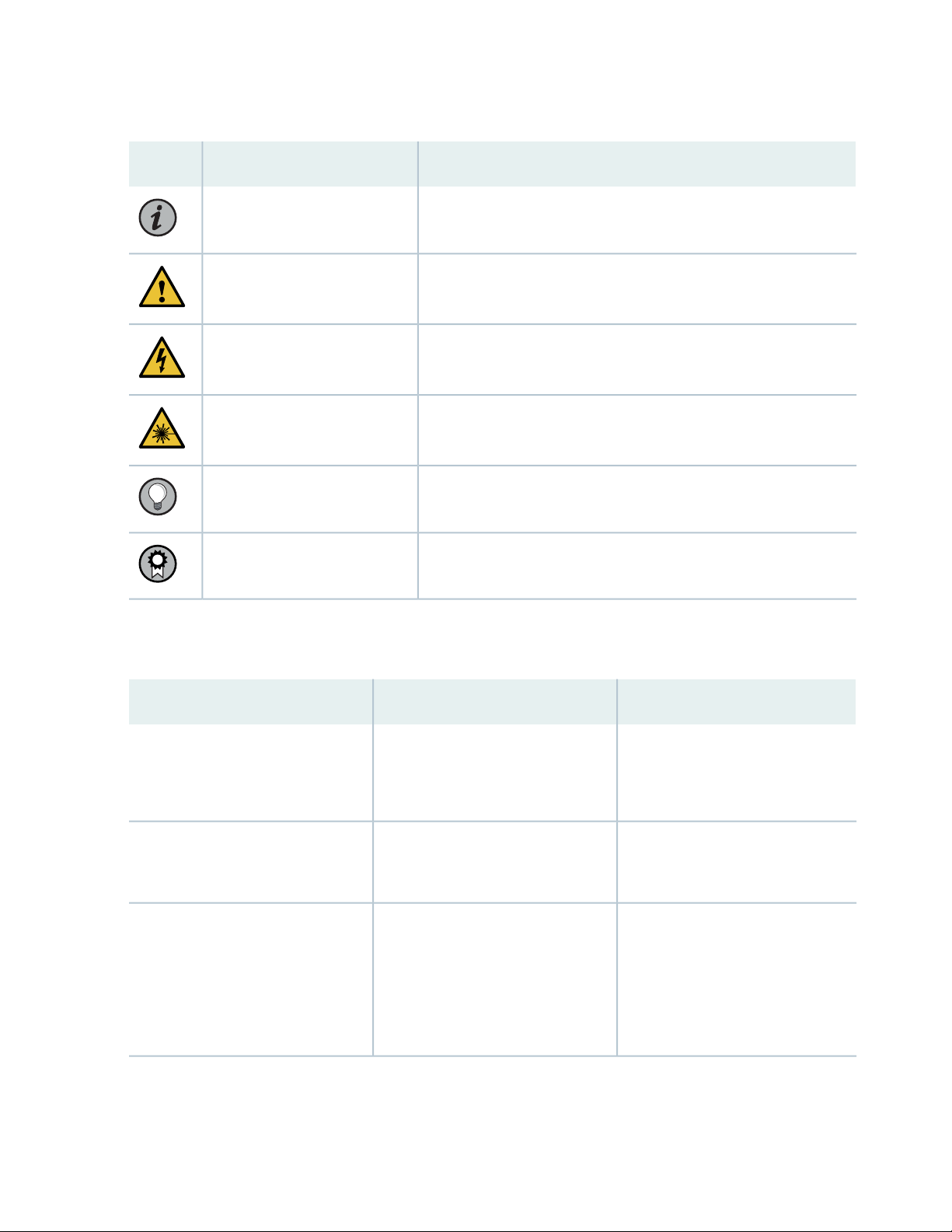
Table 1: Notice Icons
xxiv
DescriptionMeaningIcon
Indicates important features or instructions.Informational note
Caution
Indicates a situation that might result in loss of data or hardware
damage.
Alerts you to the risk of personal injury or death.Warning
Alerts you to the risk of personal injury from a laser.Laser warning
Indicates helpful information.Tip
Alerts you to a recommended use or implementation.Best practice
Table 2 on page xxiv defines the text and syntax conventions used in this guide.
Table 2: Text and Syntax Conventions
ExamplesDescriptionConvention
Fixed-width text like this
Italic text like this
Represents text that you type.Bold text like this
Represents output that appears on
the terminal screen.
Introduces or emphasizes important
•
new terms.
Identifies guide names.
•
Identifies RFC and Internet draft
•
titles.
To enter configuration mode, type
the configure command:
user@host> configure
user@host> show chassis alarms
No alarms currently active
A policy term is a named structure
•
that defines match conditions and
actions.
Junos OS CLI User Guide
•
RFC 1997, BGP Communities
•
Attribute
Page 24

Table 2: Text and Syntax Conventions (continued)
xxv
ExamplesDescriptionConvention
Italic text like this
Text like this
< > (angle brackets)
| (pipe symbol)
Represents variables (options for
which you substitute a value) in
commands or configuration
statements.
Represents names of configuration
statements, commands, files, and
directories; configuration hierarchy
levels; or labels on routing platform
components.
variables.
Indicates a choice between the
mutually exclusive keywords or
variables on either side of the symbol.
The set of choices is often enclosed
in parentheses for clarity.
Configure the machine’s domain
name:
[edit]
root@# set system domain-name
domain-name
To configure a stub area, include
•
the stub statement at the [edit
protocols ospf area area-id]
hierarchy level.
The console port is labeled
•
CONSOLE.
stub <default-metric metric>;Encloses optional keywords or
broadcast | multicast
(string1 | string2 | string3)
# (pound sign)
[ ] (square brackets)
Indention and braces ( { } )
; (semicolon)
GUI Conventions
Indicates a comment specified on the
same line as the configuration
statement to which it applies.
Encloses a variable for which you can
substitute one or more values.
Identifies a level in the configuration
hierarchy.
Identifies a leaf statement at a
configuration hierarchy level.
rsvp { # Required for dynamic MPLS
only
community name members [
community-ids ]
[edit]
routing-options {
static {
route default {
nexthop address;
retain;
}
}
}
Page 25

Table 2: Text and Syntax Conventions (continued)
xxvi
ExamplesDescriptionConvention
Bold text like this
> (bold right angle bracket)
Represents graphical user interface
(GUI) items you click or select.
Separates levels in a hierarchy of
menu selections.
In the Logical Interfaces box, select
•
All Interfaces.
To cancel the configuration, click
•
Cancel.
In the configuration editor hierarchy,
select Protocols>Ospf.
Documentation Feedback
We encourage you to provide feedback so that we can improve our documentation. You can use either
of the following methods:
Online feedback system—Click TechLibrary Feedback, on the lower right of any page on the Juniper
•
Networks TechLibrary site, and do one of the following:
Click the thumbs-up icon if the information on the page was helpful to you.
•
Click the thumbs-down icon if the information on the page was not helpful to you or if you have
•
suggestions for improvement, and use the pop-up form to provide feedback.
E-mail—Send your comments to techpubs-comments@juniper.net. Include the document or topic name,
•
URL or page number, and software version (if applicable).
Requesting Technical Support
Technical product support is available through the Juniper Networks Technical Assistance Center (JTAC).
If you are a customer with an active Juniper Care or Partner Support Services support contract, or are
Page 26

covered under warranty, and need post-sales technical support, you can access our tools and resources
online or open a case with JTAC.
JTAC policies—For a complete understanding of our JTAC procedures and policies, review the JTAC User
•
Guide located at https://www.juniper.net/us/en/local/pdf/resource-guides/7100059-en.pdf.
Product warranties—For product warranty information, visit https://www.juniper.net/support/warranty/.
•
JTAC hours of operation—The JTAC centers have resources available 24 hours a day, 7 days a week,
•
365 days a year.
Self-Help Online Tools and Resources
For quick and easy problem resolution, Juniper Networks has designed an online self-service portal called
the Customer Support Center (CSC) that provides you with the following features:
Find CSC offerings: https://www.juniper.net/customers/support/
•
Search for known bugs: https://prsearch.juniper.net/
•
xxvii
Find product documentation: https://www.juniper.net/documentation/
•
Find solutions and answer questions using our Knowledge Base: https://kb.juniper.net/
•
Download the latest versions of software and review release notes:
•
https://www.juniper.net/customers/csc/software/
Search technical bulletins for relevant hardware and software notifications:
•
https://kb.juniper.net/InfoCenter/
Join and participate in the Juniper Networks Community Forum:
•
https://www.juniper.net/company/communities/
Create a service request online: https://myjuniper.juniper.net
•
To verify service entitlement by product serial number, use our Serial Number Entitlement (SNE) Tool:
https://entitlementsearch.juniper.net/entitlementsearch/
Creating a Service Request with JTAC
You can create a service request with JTAC on the Web or by telephone.
Visit https://myjuniper.juniper.net.
•
Call 1-888-314-JTAC (1-888-314-5822 toll-free in the USA, Canada, and Mexico).
•
For international or direct-dial options in countries without toll-free numbers, see
https://support.juniper.net/support/requesting-support/.
Page 27

1
PART
Overview
MX2010 Router Overview | 3
Chassis Components and Descriptions | 5
Alarm and Display Components | 29
Cable and Rack Management | 37
Cooling System | 45
Host Subsystem Components | 51
Interface Modules— ADCs, MPCs, and MICs | 69
Power System | 95
Page 28

Page 29

CHAPTER 1
MX2010 Router Overview
IN THIS CHAPTER
MX2010 Router Overview | 3
MX2010 Router Overview
The MX2010 Universal Routing Platform is an Ethernet-optimized router that provides both switching
and carrier-class Ethernet routing. The MX2010 router supports service provider core, converged core
and edge, and edge applications, and enables a wide range of business and residential and services, including
high-speed transport and VPN services, next-generation broadband multiplay services, and high-volume
Internet data center internetworking.
3
The MX2010 chassis provides redundancy and resiliency. All major hardware components including the
power system, the cooling system, the Control Board and the switch fabrics are fully redundant.
The MX2010 router is 34 rack units (U) tall. One router can be installed in an open-frame rack, four-post
rack, or cabinet. The MX2010 router has 10 dedicated line-card slots which means a maximum of 10
Modular Port Concentrators (MPCs) including adapter cards (ADCs), and Modular Interface Cards (MICs),
a host subsystem consisting of 2 Control Board with Routing Engines (CB-REs), and 8 Switch Fabric Boards
(SFBs).
Up to 2 MICs can be installed in each MPC. Fully populated, the MX2010 router supports up to 20 MICs.
For a list of the supported MPCs, and MICs, see the MX Series Interface Module Reference.
RELATED DOCUMENTATION
MX2010 Component Redundancy | 14
MX2010 Physical Specifications | 130
MX2010 Chassis Description | 7
MX2000 Host Subsystem CB-RE Description | 51
MX2010 Craft Interface Description | 29
Page 30

MX2010 Power System Description | 95
MX2010 Cooling System Description | 45
4
Page 31

CHAPTER 2
Chassis Components and Descriptions
IN THIS CHAPTER
MX Series Router Architecture | 6
MX2010 Chassis Description | 7
MX2010 Backplane Description | 13
MX2010 Component Redundancy | 14
MX2010 Field-Replaceable Units | 17
MX Series Router Packet Forwarding Engine (PFE) Architecture | 19
Line Cards Supported on MX Series Routers | 20
5
Ethernet Frame Counts and Statistics on MX Series Routers | 24
Understanding Trio Layer 2 Feature Parity | 24
MX2010 Router Hardware Components and CLI Terminology | 25
Page 32

MX Series Router Architecture
The key components of the Juniper Networks MX Series 5G Universal Routing Platforms are:
Dense Port Concentrators (DPC)
•
Modular Port Concentrators (MPC)
•
Modular Interface Cards (MIC)
•
Control Board and Routing Engine (CB-RE)
•
Switch Control Board (SCB)
•
Switch Fabric Board (SFB)
•
NOTE: The MX80 Universal Routing Platform leverages the technology used in the MPCs,
common across the MX Series, and can accommodate multiple combinations of Modular Interface
Cards (MICs) for increased flexibility. The MX80 is a single board router with a built-in RE and
one Packet Forwarding Engine (PFE). The PFE has two “pseudo” Flexible PIC Concentrators (FPC
0 and FPC 1). Because there is no switching fabric, the single PFE takes care of both ingress and
egress packet forwarding.
6
The MX Series router has been optimized for Ethernet services. Examples of the wide range of Ethernet
services provided by the MX Series include:
Virtual private LAN service (VPLS) for multipoint connectivity—Native support for VPLS services
•
Virtual leased line (VLL) for point-to-point services—Native support for point-to-point services
•
RFC 2547.bis IP/MPLS VPN (L3VPN)—Full support for MPLS VPNs throughout the Ethernet network
•
Video distribution IPTV services
•
Ethernet aggregation at the campus/enterprise edge—Supports dense 1-Gigabit Ethernet, 10-Gigabit
•
Ethernet, and 100-Gigabit Ethernet configurations, and provides full Layer 3 support for campus edge
requirements
Ethernet aggregation at the multiservice edge—Supports up to 480 1-Gigabit Ethernet ports or
•
48 10-Gigabit Ethernet ports for maximum Ethernet density along, with full Layer 2 and Layer 3 VPN
support for MSE applications
Page 33

NOTE: You can configure MX Series routers to provide simultaneous support for Layer 2 and
Layer 3 Ethernet services. In many cases, Layer 2 protocols run on some interfaces, and Layer 3
protocols run on others.
The Junos OS Layer 2 Switching and Bridging Library topic discusses Layer 2 configurations on
supported routers, including Layer 2 statement summaries and configuration statement examples.
For more complete Layer 2 configuration examples for MX Series routers, see the Ethernet
Networking Feature Guide for MX Series Routers.
For more information about configuring Layer 3 features and functions (such as class of service),
see the relevant Junos configuration guides.
RELATED DOCUMENTATION
7
Line Cards Supported on MX Series Routers | 20
MX2010 Chassis Description
The router chassis is a rigid sheet metal structure that houses all the other router components (see
Figure 1 on page 8, Figure 2 on page 10, and Figure 3 on page 11). The chassis measures
59.50 in. (151.13 cm) high, 36.20 in. (91.95 cm) deep, and 19 in. (48.26 cm) wide. The chassis can be
installed in a standard 19-in. open-frame rack, four-post rack, or an enclosed cabinet.
NOTE: There must be a minimum of 34-U of usable rack space when installing the MX2010
router into a 34-U rack.
NOTE: If you are installing the MX2010 router into a network cabinet, make sure that no
hardware, device, rack, or cabinet component obstructs the 34-U rack space from access during
installation.
The chassis includes the following features (see Figure 1 on page 8, Figure 2 on page 10, and
Figure 3 on page 11).
Front-mounting flanges for mounting in a four-post rack or cabinet.
•
Page 34

Center-mounting metal brackets for center-mounting in an open-frame rack (optional).
g007400
OK/FAIL
OK/FAIL
OK/FAIL
OK/FAIL
OK/FAIL
OK/FAIL
OK/FAIL
OK/FAIL
1
2
3
5
4
•
CAUTION: Before removing or installing components, attach an ESD strap to an ESD
point, and place the other end of the strap around your bare wrist. Failure to use an
ESD strap could result in damage to the hardware components.
WARNING: The router must be connected to earth ground during normal operation.
The chassis with standard cable managers and EMI cover measures 59.50 in. (151.13 cm) high,
19 in. (48.26 cm) wide, and 36.20 in. (91.95 cm) deep (from the front-mounting flanges to the rear of the
chassis). An extended cable manager extends the depth to 40.15 in. (102 cm).
One router can be installed in a 34-U or taller open-frame or four-post rack if the rack can support the
combined weight, which can be greater than 985 lb (446.79 kg).
8
NOTE: The dimensions also include the cable managers and EMI cover.
Figure 1: Front View of a Fully Configured MX2010 Router Chassis
Page 35

NOTE: Remove field replacement units (FRUs) from the front of the MX2010 router before you
install the router.
See Table 3 on page 9 for information about the components on the front of the MX2010 router.
Table 3: Front Components in a Fully Configured MX2010 Router
Number of FRUsSlotsComponent DescriptionComponent No.
1–Craft interface1
1–Card-cage air filter2
9
3
Engine (CB-RE)
4
(SFBs)
5
MICs
20 and 1Control Board and Routing
80 through 7Switch Fabric Boards
100 through 9MPCs with ADCs and
NOTE: A combination card-cage cable manager and air filter is installed over the CB-REs and
SFBs.
NOTE: Remove field replacement units (FRUs) from the rear of the MX2010 router before you
install the router.
See Table 4 on page 10 for information about components on the back of an AC-powered MX2010 router.
Page 36

Figure 2: Rear View of a Fully Configured AC-Powered MX2010 Router Chassis
g007447
D
1
2
5
3
4
6
7
10
Table 4: Rear Components in a Fully Configured AC-Powered MX2010 Router
Number of FRUsSlotsComponent DescriptionComponent No.
Upper fan trays (two)1
(behind cage door)
2
or wye, or a single-phase AC
PDM
5
or wye, or a single-phase AC
PDM
Lower fan trays (two)7
(behind access door)
2Fan tray 2 and fan tray 3
1PDM1/Input1AC PDM—Three-phase delta
90 through 8AC PSM3
1–PSM air filter4
1PDM0/Input0AC PDM—Three-phase delta
1–Fan tray air filter6
2Fan tray 0 and fan tray 1
Page 37

Figure 3: Rear View of a Fully Configured DC-Powered MX2010 Router Chassis
D
g007401
1
2
8
7
5
3
4
6
11
NOTE: Remove field replacement units (FRUs) from the rear of the MX2010 router before you
install the router.
See Table 5 on page 11 for information about router components on the back of a DC-powered MX2010
router.
Table 5: Rear Components in a Fully Configured DC-Powered MX2010 Router
Number of FRUsSlotsComponent DescriptionComponent No.
Upper fan trays (two)1
(behind cage door)
2Fan tray 2 and fan tray 3
1PDM1/Input1DC PDM2
90 through 8DC PSM3
1–PSM air filter4
1PDM0/Input0DC PDM5
Page 38

Table 5: Rear Components in a Fully Configured DC-Powered MX2010 Router (continued)
g007434
ESD
points
Number of FRUsSlotsComponent DescriptionComponent No.
12
6
or extended)
Lower fan trays (two)8
(behind access door)
2–DC cable manager (standard
1–Fan tray air filter7
2Fan tray 0 and fan tray 1
The MX2010 router has two electrostatic discharge (ESD) points. These are located on either side of the
MPCs on the front of the chassis (see Figure 4 on page 12).
Figure 4: MX2010 Router ESD Points
RELATED DOCUMENTATION
MX2010 Physical Specifications | 130
Installing the MX2010 Mounting Hardware for a Four-Post Rack or Cabinet | 233
Page 39

MX2010 Router Grounding Specifications
MX2010 Chassis Moving Guidelines | 129
MX2010 Backplane Description
The MX2010 router consist of a signal backplane and a power backplane that connects PSMs and PDMs
to the chassis. The adapter cards (ADCs) are carrier cards used to house the MPCs. The MPCs install into
the bottom card-cage backplanes from the front of the chassis and mate to the signal backplane to connect
to the Switch Fabric Boards (SFBs) and the Control Board and Routing Engines (CB-REs). The backplane
connects 10 line cards to 8 SFBs and 2 CB-REs. The SFBs and CB-REs install into the top from the front
of the chassis. The PSMs install into the bottom power backplane, and the PDMs mate to the bottom
power backplane. The cooling system components also connect to the top and bottom backplane.
The backplane performs the following major functions:
Data path—Data packets are transferred across the backplane between the MPCs through the fabric
•
ASICs on the SFBs.
13
Power distribution—The router PDMs relay power from the feeds to the input of the PSMs through the
•
power midplane. In addition, the output power from PSMs is distributed to the components of the chassis
(MPCs, SFBs, and CB-REs), using the power backplane.
Control/management path—The backplane provides management and control path connectivity among
•
the various system components.
RELATED DOCUMENTATION
MX2010 Router Overview | 3
MX2010 Chassis Description | 7
MX2010 Modular Port Concentrator Description | 70
MX2000 Switch Fabric Board (SFB) Overview | 66
MX2000 Host Subsystem CB-RE Description | 51
MX2010 Modular Interface Card Description | 79
MX2010 Power System Description | 95
MX2010 Power Midplane Description | 100
Page 40

MX2010 Component Redundancy
g007087
PDM 0
(feed A)
PDM 1
(feed B)
PSM
0
PSM
1
PSM
8
A fully configured router is designed so that no single point of failure can cause the entire system to fail.
Only a fully configured router provides complete redundancy. All other configurations provide partial
redundancy. The following major hardware components are redundant:
Host subsystem—The host subsystem consists of a combined Control Board and Routing Engine (CB-RE)
•
functioning together. The router can have one or two host subsystems. If two host subsystems are
installed, one functions as the master and the other functions as the backup. If the master host subsystem
(or either of its components) fails, the backup can take over as the master.
DC power system—The MX2010 DC power system is made up of three components: nine power supply
•
modules (PSMs), two power distribution modules (PDMs), and a power midplane (PMP). The power
system distributes power from a pool of 22.5 KW (20 KW for PSM non-redundant and 2.5 KW reserved
for PSM redundancy). This pool provides power to ten line-card slots, four fan trays and critical FRUs.
These critical FRUs consist of two CB-REs and eight SFBs located in the top portion of the chassis.
DC power feed redundancy—The MX2010 router power system is feed redundant. Each PSM can be
•
connected to two separate feeds from different sources that are used to provide feed redundancy. There
are two PDMs per power subsystem that carry nine feeds each. Users should connect feeds from one
power source to one PDM and feeds from the other power source to the second PDM of the power
subsystem (see Figure 5 on page 14).
14
Figure 5: DC Power System Feed Redundancy
Each PSM has a set of two DIP switches located on the faceplate. These DIP switches are used to indicate
whether a user wants to connect one feed to the power system, two feeds, or none. These DIP switches
provide critical information to the power management system to help generate alarms in case of a feed
failure or a wrong connection. Each PDM has an LED per feed indicating whether the feed is active or
not, or whether the feed is connected properly. See “MX2010 DC Power Supply Module (-48 V)
Description” on page 116.
AC power system—The MX2010 supports connection of a three-phase AC power system. There are
•
two types of three-phase power systems: the three-phase delta and three-phase wye. The AC power
Page 41

going to the PSMs is split into three individual phases—each PSM works on a single phase. This means
g007085
AC PS_0
2800W
input
AC PS_3
2800W
input
AC PS_1
2800W
input
AC PS_4
2800W
input
AC PS_2
2800W
input
AC PS_5
2800W
input
A1
B1
AC PS_8
2800W
input
A2
B2
C2
AC PS_6
2800W
input
AC PS_7
2800W
input
C1
g007086
AC PS_0
2800W
input
AC PS_3
2800W
input
AC PS_2
2800W
input
AC PS_5
2800W
input
A1
B1
C1
AC PS_1
2800W
input
AC PS_4
2800W
input
NE1
C2
NE2
AC PS_6
2800W
input
A2
B2
AC PS_7
2800W
input
AC PS_8
2800W
input
the power system works independent of the kind of AC feed is connected. The user can connect one
or two feeds, depending on the power system configuration (number of PSMs, redundancy, and so on).
Each phase from each of the two feeds is distributed among one or two PSMs (one feed has each phase
going to two PSMs, and the other feed has each phase going to a single PSM). See Figure 6 on page 15
and Figure 7 on page 15.
Figure 6: Power Distribution from Three-Phase Feed Delta PDM to the AC PSMs
15
Figure 7: Power Distribution from Three-Phase Feed Wye PDM to the AC PSMs
The AC power system is feed redundant—each PSM takes in two AC feeds and uses one of the two.
One AC feed is active at a time. If one feed fails, the PSM automatically switches over to the other feed
without disrupting system function (see “MX2000 Three-Phase Delta AC Power Distribution Module
Page 42

Description” on page 100, “MX2000 Three-Phase Wye AC Power Distribution Module Description” on
page 102, and “MX2000 AC Power Supply Module Description” on page 107).
AC power requirements—Table 6 on page 16 shows the MX2010 current requirements for the three-phase
•
delta and wye power feeds.
Table 6: AC PDM Delta and Wye Current Requirements
16
(minimum–nominal)
(line-to-line) for delta (per
phase)
(minimum–nominal)
(line-to-neutral) for wye
(per phase)
NOTE: This is the minimum required to provide 2.5 KW per PSM. Based on facilities
guidelines, you should over-provision the MX2010 router. The two numbers listed in the
current columns reflect the distribution of phases from the feed to PSM. For example, from
one feed each phase goes to two PSMs and from other feed each phase goes to only one
PSM.
Current Delta per
Three-Phase PDMInput FeedThree-Phase Voltage
Current Wye per
Three-Phase PDM
–50 A1200 V
–25 A2
30 A–1200 V
15 A–2
Power distribution modules (PDMs)—In the DC configuration, each system provides N+1 PSM redundancy
•
along with N+N feed redundancy. The power feeds from different sources need to be connected to
different PDMs. If feeds that connect to one PDM fail in a redundant configuration, the other feed starts
to provide full power.
NOTE: Depending on the voltage of the DC feeds, power can be drawn from both feeds.
The feed with higher voltage provides more power. If the difference between the voltages
is sufficient, then the higher voltage feed provides all the power. When the voltages are
exactly the same, equal power is drawn from both feeds.
A total of two PDMs can be installed into a router. Each DC PDM (-48 V) operates with up to nine
separate feeds of either 60-A or 80-A current limit. The capacity of these feeds is relayed to system
software through a switch located on the DC PDM. Each DC PDM (240 V China)—operates with nine
feeds each. The MX2010 router supports two types of three-phase power system PDMs. The three-phase
Page 43

delta and three-phase wye. Individual phases are taken from three-phase feeds to individual PSMs. One
AC feed provides power to six PSMs, while the second input feed provides power to the remaining three
PSMs (supporting a total of nine PSMs).
Power supply modules (PSMs)—All nine AC or DC PSMs in a system share the load. If one PSM fails in
•
a redundant configuration, the remaining eight PSMs provide power to FRUs. In the AC or DC
configuration, up to nine PSMs might be required to supply power to a fully configured router. Nine
PSMs supply power to the two CB-REs (active and redundant), eight SFBs, ten MPCs, and four fan trays
(active and redundant).
Cooling system—The cooling system has a total of four fan trays— two per cooling zone (cooling zone
•
0 and cooling zone 1)—which are controlled and monitored by the host subsystem. Each cooling zone
consists of two fan trays. The bottom fan trays are used to cool the bottom half of the CB-REs and SFBs,
along with the ten line cards. The top fan trays are used to cool the top half of the CB-REs and SFBs. If
a fan fails or the temperature rises above the temperature threshold, the speed of the remaining fans in
the zone is automatically adjusted to keep the temperature within the acceptable range (see “MX2010
Cooling System Description” on page 45).
17
RELATED DOCUMENTATION
MX2010 Router Overview | 3
Displaying MX2010 Router Components and Serial Numbers | 733
Guidelines for Packing Hardware Components for Shipment | 693
Returning a Hardware Component to Juniper Networks, Inc. | 696
MX2010 Field-Replaceable Units
Field-replaceable units (FRUs) are router components that can be replaced at the customer site (see
Table 7 on page 18). Replacing most FRUs requires minimal router downtime. The router uses the following
types of FRUs:
Hot-removable and hot-insertable FRUs—You can remove and replace these components without
•
powering off the router or disrupting the routing functions.
Hot-pluggable FRUs—You can remove and replace these components without powering off the router,
•
but the routing functions of the system are interrupted when the component is removed.
Page 44

NOTE: Before you replace most host subsystem components, such as the Control Board
and Routing Engine (CB-RE), you must take the host subsystem offline.
You must power off the Control Board and Routing Engine (CB-RE) before replacing a
CompactFlash card or solid-state drive in a Routing Engine.
Table 7 on page 18 lists the FRUs for the MX2010 router.
Table 7: Field-Replaceable Units
Hot-Pluggable FRUsHot-Removable and Hot-Insertable FRUs
18
PSM air filter
•
Air filter (lower)
•
Lower cable manager
•
Craft interface
•
Switch Fabric Board (SFB) (if redundant)
•
Backup CB-RE (if redundant)
•
Master CB-RE (if nonstop active routing is
•
configured)
Modular Port Concentrators (MPCs)
•
Adapter cards
•
Modular Interface Cards (MICs)
•
AC power supply modules (if redundant)
•
DC power supply modules (if redundant)
•
Fan trays
•
DC power distribution modules (if
•
redundant)
AC power distribution modules (if
•
redundant)
Control Board and Routing
•
Engine (CB-RE) (nonredundant)
Switch Fabric Board (SFB)
•
(nonredundant)
NOTE: A PDM can be replaced without
impacting services. However, you must first
disconnect it from power. See the PDM
replacement procedures listed in Related
Documentation.
RELATED DOCUMENTATION
Page 45

Replacing an MX2020 Three-Phase Wye AC Power Distribution Module | 590
Replacing an MX2000 Three-Phase Delta AC Power Distribution Module | 571
Replacing an MX2000 DC Power Distribution Module (-48 V) | 484Replacing an MX2000 DC Power
Distribution Module (-48 V) | 484Replacing an MX2000 DC Power Distribution Module (-48 V) | 484
Replacing an MX2010 Three-Phase Wye AC Power Distribution Module
Taking an MX2000 Host Subsystem Offline | 685
Tools and Parts Required for Replacing MX2010 Hardware Components | 430
MX2010 Router Hardware Components and CLI Terminology | 25
Replacing the MX2010 Craft Interface | 468
Replacing an MX2010 Fan Tray | 508
Replacing the MX2010 Air Filters | 449
MX Series Router Packet Forwarding Engine (PFE) Architecture
19
The general architecture for the MX Series router is shown in Figure 8 on page 19.
Figure 8: MX Series Router Packet Forwarding and Data Flow
RELATED DOCUMENTATION
Line Cards Supported on MX Series Routers | 20
Page 46

Line Cards Supported on MX Series Routers
IN THIS SECTION
FPCs and PICs | 21
DPCs | 21
MPCs and MICs | 22
Switch Fabric Boards (SFB, SFB2, SFB3) | 22
Switch Control Boards | 23
MX2000 ADC | 23
Routing Engines and CB-REs | 23
20
Juniper Networks MX Series 5G Universal Routing Platforms process incoming and outgoing packets using:
Modular Port
Concentrator
(MPC) with a
Modular Interface
Card (MIC)
Provides physical
interfaces for
MX2000 series
routers.
20——Maximum Supported
Switch Control Board
(SCB, SCBE, SCBE2,
SCBE3)
House the routing
•
engine
Control power to
•
MPCs
Monitor and control
•
system functions
such as fan speed
and the system front
panel
Manage clocking,
•
resets, and boots
Description
on MX2020
Dense Port
Concentrator (DPC)
Provides multiple
physical interfaces
and Packet
Forwarding Engines
(PFEs) on a single
board that installs into
a slot within the
MX240, MX480, and
MX960 routers.
Flexible PIC
Concentrator
(FPC) with
Physical Interface
Card (PIC)
Provides physical
interfaces for
MX240, MX480,
and MX960 routers.
on MX2010
10——Maximum Supported
Page 47

21
Modular Port
Concentrator
(MPC) with a
Modular Interface
Card (MIC)
121212Maximum Supported
666Maximum Supported
323Maximum Supported
type-fpc/pic/porttype-fpc/pic/portConfiguration Syntax
Switch Control Board
(SCB, SCBE, SCBE2,
SCBE3)
on MX960
on MX480
on MX240
Dense Port
Concentrator (DPC)
Flexible PIC
Concentrator
(FPC) with
Physical Interface
Card (PIC)
FPCs and PICs
A Flexible PIC Concentrator (FPC) occupies two Dense Port Concentrator (DPC) slots on an MX240,
MX480, MX960 router. Each FPC supports up to two Physical Interface Cards (PICs). FPCs install vertically
in the MX960 router chassis, and horizontally in the MX480 and MX240 router chassis. The maximum
number of supported FPCs varies per router:
Physical Interface Cards (PICs) provide physical interfaces for MX240, MX480, MX960 routers. They install
into the Flexible PIC Concentrators (FPCs). PICs and FPCs function similarly to MICs and MPCs. The
maximum number of supported PICs varies per router:
DPCs
A Dense Port Concentrator (DPC) provides multiple physical interfaces and Packet Forwarding Engines
(PFEs) on a single board that installs into a slot within the MX240, MX480, and MX960 routers. DPCs
install vertically in the MX960 router chassis and horizontally in the MX480 and MX240 router chassis.
The maximum number of supported DPCs varies per router:
MX960 router— up to 12 DPCs
•
MX480 router— up to 6 DPCs
•
MX240 router— up to 3 DPCs
•
Page 48

NOTE: In the Junos OS CLI, you use the FPC syntax to configure or display information about
DPCs, and you use the PIC syntax to configure or display information about Packet Forwarding
Engines on the DPCs.
In addition to Layer 3 routing capabilities, the DPCs also have many Layer 2 functions that allow MX
Series routers to be used for many virtual LAN (VLAN) and other Layer 2 network applications.
MPCs and MICs
Modular Port Concentrators (MPCs) with Modular Interface Cards (MICs) provide packet forwarding
services and physical interfaces for MX routers. MICs install into MPCs and function similarly to PICs and
FPCs. MPCs install vertically in the MX2020, MX2010, MX2008, and MX960 router chassis, and horizontally
in the MX480 and MX240 router chassis. On MX5, MX10, MX40, MX80, and MX104 routers, MICs install
directly into the router chassis. There are also fixed-configuration MPCs, with built-in network ports and
services functionality. The maximum number of supported MPCs varies per MX router and hardware
configuration:
22
MX2020 router— up to 20 MPCs
•
MX2010 router— up to 10 MPCs
•
MX960 router— up to 12 MPCs
•
MX480 router— up to 6 MPCs
•
MX240 router— up to 3 MPCs
•
MX80 router— .
•
NOTE: The MX80 router is available in a modular configuration chassis (MX80) or fixed
configuration chassis (MX80-48T). Both chassis have a fixed 10-Gigabit Ethernet MIC with four
ports for uplink connections. The modular MX80 chassis has two dedicated slots for MICs. The
fixed configuration MX80 router has an additional 48 10/100/1000Base-T Ethernet ports.
Switch Fabric Boards (SFB, SFB2, SFB3)
Switch Fabric Boards (SFBs) provide increased fabric bandwidth per slot. Up to eight SFBs, SFB2s, or SFB3s
can be installed in an MX2020 or MX2010 router. The SFBs install vertically into the front of the chassis
in the slots labeled 0 through 7.
Page 49

NOTE: All switch fabric boards in the chassis must be the same type. Mixed mode is not
supported.
Switch Control Boards
Switch Control Boards (MX-SCB, MX-SCBE, MX-SCBE2, and MX-SCBE3) provide full line-rate performance
and redundancy without a loss of bandwidth. MX-series SCBs feature an integrated switch fabric that
connects to all slots in the chassis in a nonblocking architecture. The SCBs house the routing engine, control
power to MPCs, monitor and control system functions such as fan speed and the system front panel, and
manage clocking, resets, and boots. The SCB is a single-slot card and has a carrier for the routing engine
on the front.
SCBs install vertically in the MX2020, MX2010, and MX960 chassis, and horizontally in the MX480 and
MX240 chassis. The number of supported SBCs varies per router:
23
MX240 and MX480 routers— 2 SCBs for 1 + 1 MX SCB redundancy when used with the DPC line cards
•
MX960 router— 3 SCBs for 2 + 1 redundancy when used with the DPC line cards
•
MX2010 and MX2020 routers— 8 SCBs
•
MX2000 ADC
The MX2000 ADC is a special line card adapter (ADC) that enables MX2010 and MX2020 routers to use
smaller form-factor MPCs (MPC1E, MPC2E, and MPC3E). The ADC is merely a shell that accepts line cards
in the front and converts power and switch fabric in the rear. ADCs install vertically in the MPC slot on
the front of the router. For more information about the MX2000 ADC, see “MX2000 Adapter Card (ADC)
Description” on page 69.
Routing Engines and CB-REs
Routing engines and Control Boards with Routing Engines (CB-REs) provide the software processes that
run Junos OS. The routing engine maintains the routing tables, manages the routing protocols used on the
router, controls the router interfaces, controls some chassis components, and provides the interface for
system management and user access to the router. Each CB-RE is a combined Routing Engine and Switch
Control Board in one unit.
RELATED DOCUMENTATION
MX Series Router Architecture | 6
Page 50

MX Series Router Packet Forwarding Engine (PFE) Architecture | 19
Ethernet Frame Counts and Statistics on MX Series Routers | 24
Ethernet Frame Counts and Statistics on MX Series Routers
The following considerations apply to Ethernet frame counts and statistics on Juniper Networks MX Series
5G Universal Routing Platforms:
Interface counters do not include the 7-byte Ethernet frame preamble and the frame delimiter byte.
•
In Media Access Control (MAC) statistics. the frame size includes the MAC header and cyclical redundancy
•
check (CRC) before any VLAN rewrite or other rules are applied.
In traffic statistics, the frame size includes the Layer 2 header without the trailer CRC and after any VLAN
•
rewrite or other rules are applied.
24
RELATED DOCUMENTATION
Layer 2 and Layer 3 Features on MX Series Routers
Understanding Trio Layer 2 Feature Parity
A variety of Layer 2 features are supported on M Series and MX Series routers. The features supported
by the Trio family of line cards are listed in Table 8 on page 24.
Table 8: Trio Layer 2 Feature Parity
Feature Parity with
Junos OS ReleaseFeature
Aggregation
Feature Supported
in Junos OS Release
10.4R19.1R1MX routers only: load balancing enhancements for Layer 2 Link
10.4R19.1R1Ethernet OAM IEEE 802.1ag MIP support
10.4R19.1R1Link Layer Discovery Protocol (LLDP)
10.4R19.1R1MX Series routers only: BPDU guard
10.4R19.1R1MX Series routers only: BPDU loop guard
Page 51

Table 8: Trio Layer 2 Feature Parity (continued)
25
Feature Parity with
Junos OS ReleaseFeature
interworking
RELATED DOCUMENTATION
Protocols and Applications Supported on MPCs for MX Series Routers
MX2010 Router Hardware Components and CLI Terminology
Feature Supported
in Junos OS Release
10.4R19.1R1For next generation VPNs: IRB support with LDP-VLPS and BGP-VPLS
10.4R19.1R1MPLS: BGP multihoming for inter-AS VPLS
10.4R19.1R1MX Series routers only: Ethernet as a core-facing interface in VPLS
10.4R19.1R1Disables next-hop flood in connectivity fault management (CFM)
The MX2010 router supports the components listed in Table 9 on page 25.
Table 9: MX2010 Router Hardware Components and CLI Terminology
MX2010CHAS-BP-MX2010Chassis
MX2010-PREMIUM2-ACAC Optimized Power
Chassis
MX2010-PREMIUM2-DCDC Optimized Power
Chassis
Front Panel DisplayMX2010-CRAFTCraft interface panel
DescriptionCLI NameHardware Model NumberComponent
“MX2010 Physical
Specifications” on page 130
“MX2010 Chassis Description”
on page 7
“MX2010 Craft Interface
Description” on page 29
Page 52

Table 9: MX2010 Router Hardware Components and CLI Terminology (continued)
DescriptionCLI NameHardware Model NumberComponent
26
Cooling system, including air baffle, fan trays, and air filters
MX2K-FANTRAYOptimized Power Fan
Tray
Power System Components
MX2000-PDM-DCPower distribution
module (PDM)
MX2K-PDM-DC240V
172mm FanTray - 6 FansMX2000-FANTRAYFan tray
Optimized Power fan
tray
N/AMX2000-UPR-BAFFLEAir baffle
N/AMX2010-FLTR-KIT-SAir filter kit
N/AMX2000-PDM-BLANKPDM blank cover
DC 52V Power Dist
Module
MX2K 240V HVDC
PDM
“MX2010 Cooling System
Description” on page 45
“MX2010 Power System
Description” on page 95
“MX2010 DC Power
Distribution Module (-48 V)
Description” on page 111
MX2000 DC Power Distribution
Module (240 V China) Description
MX2000-PDM-AC-DELTA
MX2K-PDM-OP-AC
MX2K-PDM-OP-DC
AC Delta Power Dist
Module
AC Y Power Dist ModuleMX2000-PDM-AC-WYE
Single-phase AC PDMMX2K-PDM-AC-1PH
Single-phase AC PDM
(6+1)
Optimized Power DC
PDM (6+1)
“MX2000 Three-Phase Delta AC
Power Distribution Module
Description” on page 100
“MX2000 Three-Phase Wye AC
Power Distribution Module
Description” on page 102
Page 53

Table 9: MX2010 Router Hardware Components and CLI Terminology (continued)
DescriptionCLI NameHardware Model NumberComponent
27
(PSM)
MX2000-PSM-ACPower supply module
MX2000-PSM-DC
See MX Series Interface Module ReferenceMIC
See MX Series Interface Module ReferenceMPC
N/AMX2000-PSM-BLANKPSM blank cover
AC 52V Power Supply
Module
DC 52V Power Supply
Module
MX2K 240V HVDC PSMMX2K-PSM-DC240V
N/AMX2000-LC-BLANKMPC blank cover
Adapter CardMX2000-LC-ADAPTERADC
“MX2010 Power System
Description” on page 95
MX2000 DC Power Supply
Module (240 V China) Description
“MX2010 Modular Interface
Card Description” on page 79
“MX2010 Modular Port
Concentrator Description” on
page 70
“MX2000 Adapter Card (ADC)
Description” on page 69
Routing Engine
(CB-RE)
Transceiver
Reference
RELATED DOCUMENTATION
N/AMX2000-RE-SFB-BLANKSFB blank cover
Switch Fabric BoardMX2000-SFBSFB
N/AMX2000-RE-SFB-BLANKCB-RE blank cover
Control BoardRE-MX2000-1800X4Control Board and
RE-S-1800x4RE-MX2000-1800X4Routing Engine
XcvrSee MX Series Interface Module
“MX2000 Switch Fabric Board
(SFB) Overview” on page 66
“RE-MX2000-1800x4 CB-RE
Description” on page 52
“Installing an SFP or XFP into an
MX2000 MPC or MIC” on
page 427
Page 54

MX2010 Router Overview | 3
MX Series Router Interface Names
MX2010 Port and Interface Numbering | 90
28
Page 55

CHAPTER 3
g007402
9
10
11
1
2 3 4 5 6
7
8
Alarm and Display Components
IN THIS CHAPTER
MX2010 Craft Interface Description | 29
MX2010 Component LEDs on the Craft Interface | 31
MX2010 Alarm Relay Contacts on the Craft Interface | 34
MX2010 Alarm LEDs and Alarm Cutoff/Lamp Test Button | 35
29
MX2010 Craft Interface Description
The craft interface enables the user to view status and troubleshooting information at a glance and to
perform many system control functions. It is hot-insertable and hot-removable.
The craft interface is located on the front of the router above the upper fan tray and contains LEDs for
the router components, the alarm relay contacts, and alarm cutoff button (see Figure 9 on page 29).
Table 10 on page 30 describes the LEDs, buttons, and connectors.
Figure 9: Front Panel of the Craft Interface
Page 56

Table 10: Craft Interface LEDs, Buttons, and Connectors
30
DescriptionLabelFunction No.
Status LEDs for PSMs 0 through 8PSM1
Status LEDs for fan trays 0 through 3FANTRAYS2
3
RE0 (MASTER, ONLINE, and
OFFLINE)
RE1 (MASTER, ONLINE, and
OFFLINE)
MINOR ALARM4
MAJOR ALARM5
ACO/LT6
M/S CHASSIS NUM7
Two sets of status LEDs per host subsystem.
There are three LEDs per Routing Engine.
Minor Alarm LED for monitoring or maintaining
the MX2010
Major Alarm LED for critical conditions, which
can result in system shutdown
Alarm Cutoff/ Lamp Test Button. Turns off both
minor and major alarms and deactivates the
device attached to the corresponding alarm relay
contact on the craft interface
Chassis ID Dial and Standalone Dial. One dial is
used to indicate the chassis number for
multi-chassis configurations. The second dial is
used to indicate whether the chassis is operating
in standalone mode or as part of a multichassis
system.
8
MINOR ALARM–[NC C NO]
MAJOR ALARM–[NC C NO]
CB-RE 0 and CB-RE 19
Two sets of alarm terminal contacts. Each
consisting of normal open and normal closed
relays that signal a minor or major alarm when
broken.
Online and Offline buttons located next to each
Control Board and Routing Engine (CB-RE)
enable you to take individual CB-REs offline or
online.
Status LEDs for the two CB-REs cards.
Page 57

Table 10: Craft Interface LEDs, Buttons, and Connectors (continued)
DescriptionLabelFunction No.
31
LC 0 through LC 910
SFB 0 through SFB 711
RELATED DOCUMENTATION
Replacing the MX2010 Craft Interface | 468
MX2010 Craft Interface Serial Number Label | 741
Online and Offline buttons located next to each
line card enable you to take individual line cards
offline or online.
Status LEDs for the lower ten line cards.
Online and Offline buttons located next to each
SFB enable you to take individual SFBs offline
or online.
Status LEDs for eight SFBs.
MX2010 Component LEDs on the Craft Interface
IN THIS SECTION
MX2010 Host Subsystem LEDs and Buttons on the Craft Interface | 31
MX2010 Power Supply Module LEDs on the Craft Interface | 32
MX2010 Line-Card LEDs and Buttons on the Craft Interface | 32
MX2010 SFB LED and Buttons on the Craft Interface | 33
MX2010 Fan Tray LEDs on the Craft Interface | 34
MX2010 Host Subsystem LEDs and Buttons on the Craft Interface
Each host subsystem has three LEDs, located in the upper middle of the craft interface, that indicate its
status. The LEDs labeled RE0 show the status of the Routing Engine on the CB-RE in slot 0. The LEDs
Page 58

labeled RE1 show the status of the Routing Engine on the CB-RE in slot 1. Table 11 on page 32 describes
the functions of the host subsystem LEDs.
Table 11: Host Subsystem LEDs on the Craft Interface
DescriptionStateColorLabel
32
GreenMASTER
steadily
GreenONLINE
steadily
RedOFFLINE
On
steadily
Host is functioning as the master.On
Host is online and is functioning normally.On
Host is installed but the Routing Engine on the
CB-RE is offline.
Host is not installed.Off–
When placing the CB-RE offline, the Routing Engine goes offline. The Routing Engine gets powered by
the Control Board.
MX2010 Power Supply Module LEDs on the Craft Interface
Each Power Supply Module (PSM) has one bicolor LED on the craft interface that indicates its status. The
LEDs, labeled 0 through 8, are located on the upper left of the craft interface next to the PSM label.
Table 12 on page 32 describes the functions of the PSM LEDs on the craft interface.
Table 12: Power Supply Module LEDs on the Craft Interface
DescriptionStateColorLabel
GreenPSM
steadily
Red
steadily
PSM is functioning normally.On
PSM module has failed or power input has failed.On
MX2010 Line-Card LEDs and Buttons on the Craft Interface
Each line card (MPC) has one bicolor LED on the craft interface that indicates its status. The LEDs, labeled
0 through 9, are located along the bottom of the craft interface. Table 13 on page 33 describes the functions
of the LEDs.
Page 59

Table 13: Line-Card LEDs on the Craft Interface
DescriptionStateColorLabel
33
GreenOK
steadily
RedFAIL
steadily
Line card functioning normally.On
Line card is transitioning online or offline.Blinking
The slot is not online.Off–
Line card has failed.On
There are ten push buttons located next to each of the line cards on the craft interface. These buttons are
used to place the line cards online or offline. When a line card is inserted into an adapter card, and installed
into the MX2010 router, the online/offline buttons can turn both cards on or off.
NOTE: When installing an adapter card without the line card, the online/offline buttons have
no affect.
MX2010 SFB LED and Buttons on the Craft Interface
Each SFB has one tricolor LED on the craft interface that indicates its status. The SFB LED, labeled 0
through 7, are located along the bottom of the craft interface. Table 14 on page 33 describes the functions
of the SFB LED.
Table 14: SFB LED on the Craft Interface
DescriptionStateColorLabel
GreenOK
steadily
RedFAIL
steadily
SFB functioning normally.On
SFB is transitioning online or offline.Blinking
The slot is not online.Off–
SFB has failed.On
Page 60

There are eight push buttons located next to each of the SFBs on the craft interface. These buttons are
used to place the SFBs online or offline.
MX2010 Fan Tray LEDs on the Craft Interface
The fan tray LEDs, labeled 0 through 3, are located on the top middle of the craft interface.
Table 15 on page 34 describes the functions of the fan tray LEDs.
Table 15: Fan LEDs on the Craft Interface
DescriptionStateColorLabel
34
GreenFAN TRAY
Red
steadily
On
steadily
Fan is functioning normally.On
Fan in a fan tray has failed.
Fan tray has failed.
RELATED DOCUMENTATION
MX2010 Craft Interface Description | 29
MX2010 Alarm Relay Contacts on the Craft Interface | 34
MX2010 Alarm Relay Contacts on the Craft Interface
The craft interface has two alarm relay contacts for connecting the router to external alarm devices (see
Figure 10 on page 35). Whenever a system condition triggers either the red or yellow alarm on the craft
interface, the alarm relay contacts are also activated. The alarm relay contacts are located on the upper
right of the craft interface (see Table 16 on page 35).
Page 61

Figure 10: Alarm Relay Contacts
g007406
1
Table 16: Alarm Relay Contacts
35
DescriptionLabelFunction No.
1
MINOR ALARM–[NC C NO]
MAJOR ALARM–[NC C NO]
The alarm relays consist of three terminal
contacts with a normal closed (NC),
common (C), and normal open (NO) relays
that signal a minor or major alarm when
broken.
RELATED DOCUMENTATION
Disconnecting the Alarm Relay Wires from the MX2010 Craft Interface | 347
Connecting the Alarm Relay Wires to the MX2010 Craft Interface | 346
MX2010 Alarm LEDs and Alarm Cutoff/Lamp Test Button
Two large alarm LEDs are located at the upper right of the craft interface. When lit, the circular red LED
indicates a critical condition that can result in a system shutdown. A lit triangular yellow LED indicates a
less severe condition that requires monitoring or maintenance. Both LEDs can be lit simultaneously.
A condition that causes an LED to light also activates the corresponding alarm relay contact on the craft
interface.
To deactivate red and yellow alarms, press the button labeled ACO/LT (for “alarm cutoff/lamp test”), which
is located to the right of the alarm LEDs. Deactivating an alarm turns off both LEDs and deactivates the
device attached to the corresponding alarm relay contact on the craft interface.
Table 17 on page 36 describes the alarm LEDs and alarm cutoff button in more detail.
Page 62

Table 17: Alarm LEDs and Alarm Cutoff/Lamp Test Button
LED Control
NameStateColorShape
36
Description
Red
Yellow
steadily
steadily
––
Critical alarmOn
Warning alarmOn
Alarm cutoff/lamp
test button
Indicates a critical
condition that can cause
the router to stop
functioning. Possible
causes include component
removal, failure, or
overheating.
Indicates a serious but
nonfatal error condition,
such as a maintenance
alert or a significant
increase in component
temperature.
Deactivates red and
yellow alarms. Causes all
LEDs on the craft
interface to light (for
testing) when pressed and
held.
RELATED DOCUMENTATION
MX2010 Craft Interface Description | 29
MX2010 Alarm Relay Contacts on the Craft Interface | 34
MX2010 Router Overview | 3
Page 63

CHAPTER 4
Cable and Rack Management
IN THIS CHAPTER
MX2010 Cable Manager Description | 37
MX2010 Rack-Mounting Hardware | 43
MX2010 Cable Manager Description
37
IN THIS SECTION
Standard Cable Manager | 37
Extended Cable Manager | 40
The MX2010 router supports the following cable managers:
Standard Cable Manager
The standard cable manager consists of the following components:
Card-cage cable manager and air filter—MX2000-CBL-MID
•
Lower cable manager—MX2000-CBL-BTM-S
•
DC power cable manager—MX2010-DC-CBL-MGR-S
•
The lower cable manager (see Figure 11 on page 38) is located just below the bottom line-card cage, has
a removable cover that is secured by two captive screws with access to rows used for routing and securing
the cables away from the front of the Modular Port Concentrators (MPCs), and Modular Interface Cards
(MICs) (see Figure 12 on page 39).
You can use cable strips or other ties to gently secure the cables in the lower cable manager. To secure
the cables in place, loop the tie through the cable anchor and secure the tie.
Page 64

Each DC PDM has one cable manager. The DC cable manager routes cables away from the rear of the
g007421
Front bottom
Rear DC Cable (for DC PDM)
PDMs, (see Figure 11 on page 38).
You can use cable strips or other ties to gently secure the cables in the DC cable manager. To secure the
cables in place, loop the tie through the cable anchor and secure the tie. You can pull the DC cable manager
up and outward to lock it into the maintenance position.
Figure 11: MX2010 Standard Cable Managers
38
Page 65

Figure 12: Lower Cable Manager
g007424
LC
10
11
12 13 14 15 16 17 18 19
39
The card-cage cable manager (see Figure 13 on page 40 and Figure 14 on page 40) is a combination cable
tray and air filter located in the upper card cage, which has rows for routing and securing the cables away
from the front of the CB-REs, and SFBs.
You can use cable strips or other ties to gently secure the cables in the card-cage cable manager. To secure
the cables in place, loop the tie through the cable anchor and secure the tie. To access the air filter, the
cable manager needs to be opened.
Page 66

Figure 13: Card-Cage Cable Manager
OK/FAIL
OK/FAIL
OK/FAIL
OK/FAIL
OK/FAIL
OK/FAIL
OK/FAIL
OK/FAIL
g007444
g007041
40
Figure 14: Card-Cage Air Filter
Extended Cable Manager
The extended cable manager consists of the following components:
Extended lower cable manager—MX2000-CBL-BTM-XT-S
•
Extended DC cable manager—MX2020-DC-CBL-MGR-XT-S
•
Page 67

Figure 15: MX2010 Extended Cable Manager
g000010
Front upper
Front lower
Rear DC PDM
41
The extended cable manager provides additional support to route and secure a large number of cables
away from the front of the MPCs and MICs (see Figure 16 on page 42).
Page 68

Figure 16: MX2010 Lower Extended Cable Manager
g000432
LC
10
11
12 13 14 15 16 17 18 19
42
The extended DC cable manager provides additional support to route and secure a large number of cables
away from the rear of the PDMs.
You can use cable strips or other ties to gently secure the cables in the upper and lower extended cable
managers. To secure the cables in place, loop the tie through the cable anchor and secure the tie.
RELATED DOCUMENTATION
Installing the MX2010 Standard Cable Manager | 388
Installing the MX2010 Standard DC Cable Manager | 368
Replacing the MX2010 Standard Cable Managers | 459
Page 69

MX2010 Rack-Mounting Hardware
The rack-mounting hardware for the MX2010 router includes:
One large adjustable mounting shelf for mounting in four-post racks or cabinets
•
Built-in front-mounting flanges on the front of the chassis for front-mounting in a four-post rack or
•
cabinet
One open-frame mounting shelf for mounting in an open-frame rack (optional)
•
Two center-mounting brackets for mounting the router in an open-frame rack (optional)
•
Mounting screws
•
Cage-nuts
•
NOTE: There must be a minimum or 34U of usable rack space when installing the MX2010
router into a 34-U rack.
43
RELATED DOCUMENTATION
MX2010 Chassis Description | 7
MX2010 Backplane Description | 13
MX2010 Power Midplane Description | 100
Installing the MX2010 Mounting Hardware for a Four-Post Rack or Cabinet | 233
Page 70

CHAPTER 5
Cooling System
IN THIS CHAPTER
MX2010 Cooling System Description | 45
MX2010 Fan Tray LED | 48
MX2010 Cooling System Description
45
The cooling system consists of the following components:
Fan tray—MX2000-FANTRAY
•
Lower fan tray air filter—MX2010-FLTR-KIT-S
•
Air baffle—MX2000-UPR-BAFFLE
•
The cooling system components work together to keep all router components within the acceptable
temperature range. The router has four fan trays, two trays located at the top, and two trays located at
the bottom of the router that install horizontally. Each fan tray contains six fans and are 172 mm in diameter.
The fan trays are interchangeable and are hot-insertable and hot-removable.
Each fan tray has a double safety latch, so the fan tray cannot be removed in one swift motion (see
Figure 17 on page 46). To remove the fan tray, press and hold the latch until LED turns off. The secondary
latch will engage during removal. Press the secondary latch to fully remove the fan tray.
Page 71

Figure 17: Removing Fan Tray
g007025
WARNING: Before removing a fan tray, make sure the fan blades have stopped
completely.
46
The host subsystem monitors the temperature of the router components. When the router is operating
normally, the fans function at lower than full speed. If a fan fails or the ambient temperature rises above
a threshold, the speed of the remaining fans is automatically adjusted to keep the temperature within the
acceptable range (see Figure 18 on page 47 and Figure 19 on page 47). The lower fan tray filter is shown
in Figure 20 on page 48.
Page 72

Figure 18: Airflow Through the Chassis
g007408
Lower fan trays
Upper Fan trays
Power
supply
cooling
Card cage
Airflow
divider
Card cage
g007035
1
1
2
47
The MX2010 router provides a two-stage front-to-back cooling system. Air is pushed into the bottom
inlet and up through the lower fan tray, and exits through the opening between the backplanes in the
center of the chassis. This cools the bottom MPCs, and half of each SFB and CB-RE. Air is pulled through
the SFBs and all the CB-REs in the center of the chassis and is exhausted out the upper rear of the system.
The CB-REs and SFBs are equipped with an air divider to deflect the exhaust air for the bottom half of the
system out and direct the air for the top half of the system out.
Figure 19: Upper/Lower Fan Tray
2—1— STATUS LEDSafety double latch system
Page 73

WARNING: Before removing a fan tray, make sure that the fan blades have stopped
g007044
completely.
WARNING: The fan trays use a double latch safety mechanism. Press and hold the
latch until the STATUS LED turns off. Continue to press and hold the latch while
removing the fan trays.
Figure 20: Lower Fan Tray Air Filter
48
The air baffle is an optional component that can be purchased from Juniper Networks.
When installed over the upper fan tray access door, the air baffle dissipates exhausted air away from the
router.
RELATED DOCUMENTATION
Troubleshooting the MX2010 Cooling System | 706
Maintaining the MX2010 Air Filters | 609
Maintaining the MX2010 Fan Trays | 615
Maintaining the MX2010 Air Baffle | 614
MX2010 Fan Tray LED
Each fan tray (both the standard fan tray and optimized power fan tray) contains one bicolor LED located
on the front faceplate (see Table 18 on page 49). A set of four bicolor fan tray LEDs is located on the top
middle of the craft interface. For more information, see “MX2010 Component LEDs on the Craft Interface”
on page 31.
Page 74

Table 18: Fan Tray LEDs
49
DescriptionStateColorLabel
Fan tray is operating properly.OnGreenSTATUS
Fan tray is not receiving enough power to operate.OnYellow
Fan temperature may indicate warm threshold.
Fan tray is nonoperational.OnRed
One or more fans are bad or not operating.
Fan temperature may indicate high threshold.
RELATED DOCUMENTATION
MX2010 Cooling System Description | 45
Maintaining the MX2010 Fan Trays | 615
Troubleshooting the MX2010 Cooling System | 706
MX2010 Component LEDs on the Craft Interface | 31
Page 75

CHAPTER 6
Host Subsystem Components
IN THIS CHAPTER
MX2000 Host Subsystem CB-RE Description | 51
RE-MX2000-1800x4 CB-RE Description | 52
REMX2K-X8-64G and REMX2K-X8-64G-LT CB-RE Description | 56
REMX2K-X8-128G CB-RE Description | 58
CB-RE LEDs | 62
MX2000 Switch Fabric Board (SFB) Overview | 66
MX2000 Switch Fabric Board LED | 66
51
MX2000 Host Subsystem CB-RE Description
The CB-RE is a combined Routing Engine and Control Board in one unit. It performs the following functions:
Maintains the routing tables
•
Manages the routing protocols used on the router
•
Controls the router interfaces
•
Controls some chassis components
•
Provides the interface for system management and user access to the route
•
The CB-RE is hot-pluggable and installs into the front of the MX2000 chassis in vertical slots labeled 0
and 1. A USB port on the CB-RE accepts a USB memory device that allows you to load Junos OS. You can
install one or two CB-REs in the router. If two CB-REs are installed, one functions as the master and the
other acts as the backup. If the master CB-RE fails or is removed and the backup is configured appropriately,
the backup takes over as the master. If no CB-RE is installed in a slot, install a blank panel in the slot.
A minimum of one CB-RE must be installed in either slot 0 or slot 1 at all times.
CAUTION: If one CB-REs fails, do not remove the failed CB-RE until you have a
replacement or blank panel to install.
Page 76

The MX2000 line of routers supports the following CB-RE’s:
RE-MX2000-1800x4 CB-RE
•
REMX2K-X8-64G-LT CB-RE
•
NOTE: REMX2K-X8-64G-LT CB-RE has limited encryption support.
RELATED DOCUMENTATION
RE-MX2000-1800x4 CB-RE Description | 52
REMX2K-X8-64G and REMX2K-X8-64G-LT CB-RE Description | 56
Maintaining the MX2010 Host Subsystem | 647
Maintaining the MX2020 Host Subsystem
52
Taking an MX2000 Host Subsystem Offline | 685
RJ-45 Connector Pinouts for MX Series CB-RE or RCB Auxillary and Console Ports | 157
RJ-45 Connector Pinouts for an MX Series CB-RE or RCB Management Port | 158
RE-MX2000-1800x4 CB-RE Description
IN THIS SECTION
RE-MX2000-1800x4 CB-RE Front Panel | 53
RE-MX2000-1800x4 CB-RE Components | 54
RE-MX2000-1800x4 CB-RE Software | 55
RE-MX2000-1800x4 CB-RE Boot Sequence | 55
The RE-MX2000-1800x4 CB-RE runs Junos OS. Software processes that run on the CB-RE maintain the
routing tables, manage the routing protocols used on the router, control the router interfaces, control
some chassis components, and provide the interface for system management and user access to the router.
Page 77

RE-MX2000-1800x4 CB-RE Front Panel
RESET
ONLINE
OFFLINE
AUX
MGMTCONSOLE
USB
g100047
1 2 3 4 5 6 7 8
11 10 9
Figure 21 on page 53 shows the Control Board and Routing Engine (CB-RE)—RE-MX2000-1800x4.
Table 19 on page 53 describes the Control Board and Routing Engine (CB-RE)—RE-MX2000-1800x4 ports.
Figure 21: RE-MX2000-1800x4 CB-RE Front View
Table 19: Components on the RE-MX2000-1800x4
DescriptionLabelFunction No.
53
AUX1
This port is used to connect a laptop, modem,
or other auxiliary unit.
CONSOLE2
This port is used to configure the MX2000
router.
MGMT3
This port is a dedicated management channel
for device maintenance. It is also used for
system administrators to monitor and manage
the MX2000 router remotely.
USB4
This port is used to install a USB flash drive that
contains Junos OS.
Reboots the CB-RE.RESET5
ONLINE/OFFLINE6
Takes the Routing Engine on the CB-RE online
or offline.
LINK7
These LEDs are associated with each of the
SFP+ ports (XGE-0 and XGE-1) and indicate the
connection in use.
ExtClk-1 and ExtClk-28
Connects the CB-RE to two external clock
interfaces for BITS and GPS function through
a serial cable with an RJ-45 connector.
Page 78

Table 19: Components on the RE-MX2000-1800x4 (continued)
54
DescriptionLabelFunction No.
There is one bicolor LED for each external clock
interface—BITS and GPS.
These ports are used for hardware diagnostics
and are for Juniper-internal use only.
There is one bicolor LED for each CB-RE
control. The ONLINE LED indicates that the
CB-RE is transitioning online and functioning
properly. The MASTER LED indicates that this
board is a master Control Board and Routing
Engine (CB-RE) , and the OK/FAIL LED indicates
the CB-RE has failed.
11
GPS, and BITS9
XGE-0 and XGE-110
ONLINE, MASTER, and
OK/FAIL
RE-MX2000-1800x4 CB-RE Components
Each CB-RE consists of the following components:
External clock interface—Allows BITS or GPS clock source input to the centralized timing circuit, or
•
allows centralized timing to be output to BITS or GPS.
1000Base-T Ethernet controller
•
Circuits for chassis management and control.
•
Power circuits for the CB-RE.
•
Control FPGA—Provides the Peripheral Component Interconnect (PCI) interface to the routing engine.
•
Gigabit Ethernet switch that is connected to the embedded CPU complex on all components.
•
CPU—Runs Junos OS to maintain the router's routing tables and routing protocols.
•
I2C bus logic, used for low-level communication with each component.
•
DRAM—Provides storage for the routing and forwarding tables and for other routing engine processes.
•
Component redundancy circuitry.
•
USB port—Provides a removable media interface through which you can install the Junos OS manually.
•
Junos OS supports USB version 1.0.
CompactFlash card—Provides primary storage for software images, configuration files, and microcode.
•
The CompactFlash card is fixed and is inaccessible from outside the router.
Solid State Disk (non-removable)—Provides secondary storage for log files, memory dumps, and rebooting
•
the system if the CompactFlash card fails.
Page 79

Interface ports—The AUX, CONSOLE, and MGMT ports provide access to management devices. Each
•
CB-RE has one 10/100-Mbps Ethernet port for connecting to a management network, and two
asynchronous serial ports—one for connecting to a console and one for connecting to a modem or other
auxiliary device. The two ports labeled XGE-0 and XGE-1 are used for hardware diagnostics and are for
Juniper-internal use only. The ExtClk ports provide access to external timing distribution.
EEPROM—Stores the serial number of the CB-RE.
•
Reset button—Reboots the Routing Engine on the CB-RE when pressed.
•
Online/Offline button—Takes the Routing Engine on the CB-RE online or offline when pressed.
•
LEDs—Provide status of the Routing Engine on the CB-RE.
•
RE-MX2000-1800x4 CB-RE Software
The RE-MX2000-1800x4 CB-RE runs Junos OS. Software processes that run on the CB-RE maintain the
routing tables, manage the routing protocols used on the router, control the router interfaces, control
some chassis components, and provide the interface for system management and user access to the router.
55
RE-MX2000-1800x4 CB-RE Boot Sequence
The router is shipped with the Junos OS pre-installed on the CB-RE. There are three copies of software:
One copy on a USB flash drive that can be inserted into the slot on the CB-RE faceplate.
•
One copy on the CompactFlash card in the Routing Engine.
•
One copy on the Solid State Disk (SSD) in the CB-RE.
•
NOTE: The SSD is internal and cannot be removed.
The Routing Engine interface boots from the storage media in this order: the USB device (if present), then
the CompactFlash card, then the SSD, and then the LAN. Normally, the router boots from the copy of the
software on the CompactFlash card.
RELATED DOCUMENTATION
RJ-45 Connector Pinouts for MX Series CB-RE Auxiliary and Console Ports
RJ-45 Connector Pinouts for an MX Series CB-RE or RCB Management Port | 158
Removing a CB-RE from an MX2000 Router | 433
MX2000 Host Subsystem CB-RE Description | 51
Page 80

REMX2K-X8-64G and REMX2K-X8-64G-LT CB-RE Description
AUX
MGMT
DISK1
DISK2
RESET
ONLINE/
ONLINE
OK/
FAIL
MASTER
1
XGE-0 XGE-1
LINK
EXTCLK-0 EXTCLK-1
BITS
GPS
UTI
OK/FAIL
CONSOLE
g009125
RE-MX2K-X8-64G
2
OFFLINE
1 32 4
5 6 7 8
AUX
MGMT
DISK1
DISK2
RESET
ONLINE/
ONLINE
OK/
FAIL
MASTER
1
XGE-0 XGE-1
LINK
EXTCLK-0 EXTCLK-1
BITS
GPS
UTI
OK/FAIL
CONSOLE
g009093
2
OFFLINE
1 32 4
5 6 7 8
IN THIS SECTION
REMX2K-X8-64G CB-RE Components | 56
REMX2K-X8-64G and REMX2K-X8-64G-LT CB-RE Boot Sequence | 58
REMX2K-X8-64G CB-RE Components
Figure 22: REMX2K-X8-64G CB-RE Components
56
Figure 23: REMX2K-X8-64G-LT CB-RE Components
5—1— USB portsAUX port
6—2— RESET buttonCONSOLE port
7—3— XGE-0 and XGE-1 portsMGMT port
8—4— EXTCLK0 and EXTCLK1 portsONLINE/OFFLINE button
5—1— USB portsAUX port
6—2— RESET buttonCONSOLE port
7—3— XGE-0 and XGE-1 portsMGMT port
8—4— EXTCLK0 and EXTCLK1 portsONLINE/OFFLINE button
Page 81

Each Control Board-Routing Engine (CB-RE) consists of the following components:
External clock interface—Allows BITS or GPS clock source input to the centralized timing circuit, or
•
allows centralized timing to be output to BITS or GPS.
1000Base-T Ethernet controller.
•
Circuits for chassis management and control.
•
Power circuits for the CB-RE.
•
Control FPGA—Provides the Peripheral Component Interconnect (PCI) interface to the Routing Engine.
•
Gigabit Ethernet switch that is connected to the embedded CPU complex on all components.
•
CPU—Runs Junos OS as a guest OS to maintain the router's routing tables and routing protocols.
•
I2C bus logic, used for low-level communication with each component.
•
DRAM—Provides storage for the routing and forwarding tables and for other Routing Engine processes.
•
Component redundancy circuitry.
•
USB ports—Provides a removable media interface through which you can install Junos OS and Linux
•
manually. Junos OS supports USB versions, 3.0, 2.0, and 1.1.
57
Solid-state drives (nonremovable)—Provides secondary storage for log files, memory dumps, and system
•
reboot.
Interface ports—The AUX, CONSOLE, and MGMT ports provide access to management devices. Each
•
CB-RE has one 10/100/1000-Mbps Ethernet port for connecting to a management network, and two
asynchronous serial ports—one for connecting to a console and one for connecting to a modem or other
auxiliary device. The two SFP+ ports (XGE-0 and XGE-1) provide support for hardware diagnostics and
JCS port testing. The EXTCLK1 and EXTCLK2 ports provide access to external timing distribution.
NOTE: Use sheilded CAT5e cable for connecting the AUX, CONSOLE, and MGMT ports.
EEPROM in RE—Stores the field replacement unit (FRU) details of the RE.
•
EEPROM in CB—Stores the field replacement unit (FRU) details of the CB.
•
RESET button—Reboots the Routing Engine on the CB-RE when pressed.
•
ONLINE/OFFLINE button—Makes the Routing Engine on the CB-RE online or offline when pressed.
•
NOTE: The ONLINE/OFFLINE button must be pressed for a minimum 4 seconds for the
power off or power on to occur.
LEDs—Provide status of the Routing Engine on the CB-RE.
•
Page 82

REMX2K-X8-64G and REMX2K-X8-64G-LT CB-RE Boot Sequence
The router is shipped with Junos OS and Linux preinstalled on the CB-RE. There are two copies of software:
One copy on a USB flash drive that can be inserted into the slot on the CB-RE faceplate.
•
One copy each on the two SSDs in the CB-RE.
•
NOTE: The SSD is internal and cannot be removed.
The Routing Engine interface boots from the storage media in this order: the USB device, SSD1, SSD2,
and then the LAN.
RELATED DOCUMENTATION
58
Supported Routing Engines by Router
Routing Engine Specifications
REMX2K-X8-128G CB-RE Description
IN THIS SECTION
REMX2K-X8-128G CB-RE Components | 59
REMX2K-X8-128G CB-RE LEDs | 60
REMX2K-X8-128G CB-RE Boot Sequence | 61
The Routing Engine is equipped with a 8-Core 2.3 GHz processor, 128 GB memory, and 200 GB SSDs and
also supports Secure Boot for enhanced boot security.
Page 83

REMX2K-X8-128G CB-RE Components
AUX
MGMT
DISK1
DISK2
RESET
ONLINE/
ONLINE
OK/
FAIL
MASTER
1
XGE-0 XGE-1
LINK
EXTCLK-0 EXTCLK-1
BITS
GPS
UTI
OK/FAIL
CONSOLE
g100078
2
OFFLINE
1 32 4
5 6 7 8
REMX2K-X8-128G
REMX2K-X8-128G
Figure 24: REMX2K-X8-128G CB-RE Components
5—1— USB portsAUX port
6—2— RESET buttonCONSOLE port
7—3— XGE-0 and XGE-1 portsMGMT port
8—4— EXTCLK0 and EXTCLK1 portsONLINE/OFFLINE button
Each Control Board-Routing Engine (CB-RE) consists of the following components:
59
External clock interface—Allows BITS or GPS clock source input to the centralized timing circuit, or
•
allows centralized timing to be output to BITS or GPS.
1000Base-T Ethernet controller.
•
Circuits for chassis management and control.
•
Power circuits for the CB-RE.
•
Control FPGA—Provides the Peripheral Component Interconnect (PCI) interface to the Routing Engine.
•
Gigabit Ethernet switch that is connected to the embedded CPU complex on all components.
•
CPU—Runs Junos OS as a guest OS to maintain the router's routing tables and routing protocols.
•
I2C bus logic, used for low-level communication with each component.
•
DRAM—Provides storage for the routing and forwarding tables and for other Routing Engine processes.
•
Component redundancy circuitry.
•
USB ports—Provides a removable media interface through which you can install Junos OS and Linux
•
manually. Junos OS supports USB versions, 3.0, 2.0, and 1.1.
Solid-state drives (nonremovable)—Provides secondary storage for log files, memory dumps, and system
•
reboot.
Interface ports—The AUX, CONSOLE, and MGMT ports provide access to management devices. Each
•
CB-RE has one 10/100/1000-Mbps Ethernet port for connecting to a management network, and two
asynchronous serial ports—one for connecting to a console and one for connecting to a modem or other
auxiliary device. The two SFP+ ports (XGE-0 and XGE-1) provide support for hardware diagnostics and
JCS port testing. The EXTCLK1 and EXTCLK2 ports provide access to external timing distribution.
Page 84

NOTE: Use sheilded CAT5e cable for connecting the AUX, CONSOLE, and MGMT ports.
AUX
MGMT
DISK1
DISK2
RESET
ONLINE/
ONLINE
OK/
FAIL
MASTER
1
XGE-0 XGE-1
LINK
EXTCLK-0 EXTCLK-1
BITS
GPS
UTI
OK/FAIL
CONSOLE
g100079
2
OFFLINE
REMX2K-X8-128G
REMX2K-X8-128G
1 32 4
EEPROM in RE—Stores the field replacement unit (FRU) details of the RE.
•
EEPROM in CB—Stores the field replacement unit (FRU) details of the CB.
•
RESET button—Reboots the Routing Engine on the CB-RE when pressed.
•
ONLINE/OFFLINE button—Makes the Routing Engine on the CB-RE online or offline when pressed.
•
NOTE: The ONLINE/OFFLINE button must be pressed for a minimum 4 seconds for the
power off or power on to occur.
LEDs—Provide status of the Routing Engine on the CB-RE.
•
60
REMX2K-X8-128G CB-RE LEDs
Figure 25: REMX2K-X8-128G CB-RE LEDs
Table 20: REMX2K-X8-128G CB-RE LEDs
Blinking slowlyGreenONLINE
3—1— BITS, GPS, and UTI LEDsONLINE LED, OK/FAIL LED, and MASTER LED
4—2— ONLINE/OFFLINE buttonDISK1 and DISK2 LEDs
DescriptionStateColorLabel
Routing Engine is in the process of booting BIOS, and the
host OS.
Routing Engine is in the process of booting Junos OS.Blinking rapidly
Routing Engine is not online or not functioning normally.Off-
Page 85

Table 20: REMX2K-X8-128G CB-RE LEDs (continued)
DISK2
and UTI LEDs
Off
61
DescriptionStateColorLabel
Indicates presence of disk activity.BlinkingGreenDISK1 and
There is no disk activity.Off-
A valid signal is detected on the BITS, GPS or UTI ports.BlinkingGreenBITS, GPS,
The link is down due to loss of signal (LOS). Check the cable
and verify the external clock source is generating a valid
signal.
Routing Engine is powering up.On steadilyGreenOK/FAIL
Routing Engine is not powering up, which indicates failure.On steadilyYellow
This Routing Engine is the Master Routing Engine.On steadilyBlueMASTER
REMX2K-X8-128G CB-RE Boot Sequence
The router is shipped with Junos OS and Linux preinstalled on the CB-RE. There are two copies of software:
One copy on a USB flash drive that can be inserted into the slot on the CB-RE faceplate.
•
One copy each on the two SSDs in the CB-RE.
•
NOTE: The SSD is internal and cannot be removed.
The Routing Engine interface boots from the storage media in this order: the USB device, SSD1, SSD2,
and then the LAN.
RELATED DOCUMENTATION
Supported Routing Engines by Router
Routing Engine Specifications
Page 86

CB-RE LEDs
Each Routing Engine on the CB-RE (model numbers RE-MX2000-1800X4 and REMX2K-X8-64G) has three
LEDs that indicate its status. The LEDs, labeled ONLINE, MASTER, OK/FAIL, are located directly on the
faceplate of the CB-RE. Table 21 on page 62 describes the functions of the Routing Engine interface of
the CB-RE. There are three LEDs on the craft interface for each Routing Engine (RE0 and RE1). These
LEDs are labeled MASTER, ONLINE, and OFFLINE.
NOTE: The GPS LED will display when connecting to an external clocking interface.
The Control Board, part of the host subsystem, has a set of bicolor LEDs that display its status. The LEDs,
labeled LINK, GPS, BITS, and UTI are located directly on the faceplate of the CB-RE. Table 21 on page 62
describes the functions of the Control Board interface of the CB-RE. There are two LEDs on the craft
interface for each Control Board–one labeled CB-RE0 (far left) and one labeled CB-RE1 (far right). For
more information about the CB-RE and Routing Engine LEDs on the craft interface, see “CB-RE LEDs” on
page 62.
62
Table 21: CB-RE LEDs
BlueMASTER
RedOK/FAIL
GreenLINK
DescriptionStateColorLabel
CB-RE is transitioning online.BlinkingGreenONLINE
CB-RE is functioning normally.On
steadily
CB-RE is offline.Off—
CB-RE is the master.On
steadily
CB-RE has failed.On
steadily
SFP+ ports (XGE-0 and XGE-1) link connection.On
steadily
Activity on SFP+ ports (XGE-0 and XGE-1).Blinking
steadily
No link.OnYellow
Page 87

Table 21: CB-RE LEDs (continued)
63
DescriptionStateColorLabel
GreenBITS
steadily
Yellow
steadily
GreenGPS
steadily
Yellow
steadily
BITS external clocking interface is active.On
BITS external clocking interface has failed.On
BITS external clocking interface is offline.Off–
GPS external clocking interface is active.On
GPS external clocking interface has failed.On
GPS external clocking interface is offline.Off–
Figure 26: REMX2K-X8-64G CB-RE LEDs
Table 22: REMX2K-X8-64G CB-RE LEDs
Callout
from
Figure26onpage63
steadily
BlueMASTER1
steadily
DescriptionStateColorLabel
CB-RE is transitioning online.BlinkingGreenONLINE1
CB-RE is functioning normally.On
CB-RE is offline.Off—
CB-RE is the master.On
Page 88

Table 22: REMX2K-X8-64G CB-RE LEDs (continued)
Callout
from
Figure26onpage63
steadily
DescriptionStateColorLabel
RE is functioning normally.OffYellowOK/FAIL10
RE has failed.On
Indicates presence of disk activity.BlinkingGreenDISK12
There is no disk activity.Off-
Indicates presence of disk activity.BlinkingGreenDISK22
There is no disk activity.Off-
64
GreenLINK3
GreenBITS5
Yellow
GreenGPS5
Yellow
SFP+ ports (XGE0 and XGE1) links are active.On
steadily
Activity on the SFP+ ports (XGE0 and XGE1).Blinking
steadily
No link.OnYellow
BITS external clocking interface is active.On
steadily
BITS external clocking interface has failed.On
steadily
BITS external clocking interface is offline.Off–
GPS external clocking interface is active.On
steadily
GPS external clocking interface has failed.On
steadily
GPS external clocking interface is offline.Off–
Page 89

Table 22: REMX2K-X8-64G CB-RE LEDs (continued)
Callout
from
Figure26onpage63
DescriptionStateColorLabel
65
GreenUTI5
steadily
Yellow
steadily
RedOK/FAIL6
steadily
RELATED DOCUMENTATION
MX2000 Host Subsystem CB-RE Description | 51
Maintaining the MX2020 Host Subsystem
Taking an MX2000 Host Subsystem Offline | 685
UTI external clocking interface is active.On
UTI external clocking interface has failed.On
UTI external clocking interface is offline.Off–
CB has failed.On
Page 90

MX2000 Switch Fabric Board (SFB) Overview
Switch Fabric Boards (SFBs) are the data plane for the subsystems in the MX router chassis. SFBs create
a highly scalable and resilient “all-active” centralized switch fabric that delivers up to 2 Tbps of full-duplex
switching capacity to each MPC slot in an MX2000 router.
There are three models of MX SFBs:
MX2000-SFB-S Description
•
MX2000-SFB2-S Enhanced Switch Fabric Board Description
•
MX2000-SFB3 Switch Fabric Board Description
•
The SFB and SFB2 switch control board models are the same except that the SFB model has three XF
fabric chips per card whereas the SFB2 model has two PF fabric chips per card.
66
RELATED DOCUMENTATION
MX2000 Switch Fabric Board LED
MX2000 Switch Fabric Board LED
One bicolor LED on the Switch Fabric Board (SFB) indicates the status of the SFB. The LED, labeled
OK/FAIL, is located directly on the SFB. Table 23 on page 66 describes the functions of the SFB LED.
Table 23: Switch Fabric Board LED
DescriptionStateColorLabel
GreenOK/FAIL
initialized.
Fast blinking when SFB is being
identified by software.
NOTE: This is used to guide
the operator to correct any
action needed on the SFB.
SFB is online.Slow blinking when being
SFB has failed.On steadilyRed
SFB is offline.Off–
Page 91

Each SFB also has a set of bicolor LEDs on the craft interface that indicate its status. The SFB LED, labeled
0 through 7, are located along the bottom center of the craft interface. For more information about the
SFB LED on the craft interface, see “MX2010 Component LEDs on the Craft Interface” on page 31.
RELATED DOCUMENTATION
MX2000 Switch Fabric Board (SFB) Overview | 66
MX2000-SFB2-S Enhanced Switch Fabric Board Description
MX2000-SFB3 Switch Fabric Board Description
MX2000 Host Subsystem CB-RE Description | 51
67
Page 92

CHAPTER 7
Interface Modules— ADCs, MPCs, and MICs
IN THIS CHAPTER
MX2000 Adapter Card (ADC) Description | 69
MX2010 Modular Port Concentrator Description | 70
MX2010 Modular Port Concentrator LEDs | 73
MPCs Supported by MX Series Routers | 73
MX2010 MPC Terminology | 78
MX2010 Modular Interface Card Description | 79
MICs Supported by MX Series Routers | 79
69
MX2010 Modular Interface Card LEDs | 90
MX2010 Port and Interface Numbering | 90
MX2000 Adapter Card (ADC) Description
The MX2000 routers are compatible with all Trio-based MPC line cards; However, because the MX2000
routers use a newer-generation Switch Fabric Board (SFB) with faster bandwidth, smaller form-factor
MPCs must use a special Line Card Adapter (ADC). The ADC is merely a shell that accepts line cards in
the front and converts power and switch fabric in the rear. ADCs install vertically in the front of the router.
The following MPCs require an ADC:
MPC1E
•
MPC2E
•
MPC3E
•
MPC5E
•
MPC7E
•
NOTE: When a slot is not occupied by a combined ADC and MPC, you must insert a blank panel
to fill the empty slot and ensure proper cooling of the system.
Page 93

ADCs are hot-removable and hot-insertable. Figure 27 on page 70 shows the ADC supported on MX2000
OK/FAI
g007010
routers.
Figure 27: ADC for the MX2000 Routers
70
RELATED DOCUMENTATION
Maintaining the MX2010 Adapter Cards | 606
Maintaining MX2020 Adapter Cards
MPCs Supported by MX Series Routers | 73
Replacing an MX2008 MPC
MX2010 Modular Port Concentrator Description
The Modular Port Concentrators (MPCs) provides packet forwarding services. The MPCs install into an
adapter card, which in turn connects to the backplane. Modular Interface Cards (MICs) provide the physical
interfaces and install into the MPCs. The user can install up to two MICs of different media types on the
same MPC as long as the MPC supports those MICs.
NOTE: The MX2010 router also supports fixed-port MPCs.
Page 94

MICs receive incoming packets from the network and transmit outgoing packets to the network. During
g007019
this process, each MIC performs framing and high-speed signaling for its media type. Each MPC is equipped
with up to four Junos Trio chipsets, which perform control functions tailored to the MPC’s media type.
The MX2010 router supports up to 10 MPCs. For power requirements, see “Calculating DC Power
Requirements for MX2010 Routers” on page 204 and “Calculating AC Power Requirements for MX2010
Routers” on page 180.
The router has 10 dedicated line-card slots for MPCs. MPCs install vertically in the front of the router.
The dedicated slots are numbered 0 though 9 (left to right). An MPC can be installed in any line-card slot.
The user can install any combination of MPC types in the router.
When an MPC slot is not occupied by an MX2000 MPC or an adapter card with MPC, a blank MX2000
panel needs to be installed.
MPCs are hot-removable and hot-insertable. When the user installs an MPC in an operating router, the
CB-RE downloads the MPC software, the MPC runs its diagnostics, and enables the Packet Forwarding
Engines housed on the MPC. Forwarding on other MPCs continues uninterrupted during this process.
71
Figure 28 on page 71 shows a typical MPC supported on the MX2010 router. Figure 29 on page 72 shows
an MPC installed vertically in the MX2010 router. For more information about MPCs, see the MX Series
Interface Module Reference.
Figure 28: Typical MPC Supported on the MX2010 Router
Page 95

Figure 29: MPC Installed in the MX2010 Router
g007416
72
MPC Components
Each MPC consists of the following components:
MIC card carrier, which includes two MIC slots (excludes the fixed configuration MPC).
•
Fabric interfaces.
•
Two Gigabit Ethernet interfaces that allow control information, route information, and statistics to be
•
sent between the Routing Engine and the CPU on the MPCs.
Up to four Junos Trio chipsets, which perform control functions tailored to the MPC’s media type.
•
Backplane connectors and power circuitry.
•
Online button located on the craft interface, which takes the MPC online or offline when pressed.
•
OK/FAIL LED on the MPC faceplate. For more information about LEDs on the MPC faceplate, see the
•
MX Series Interface Module Reference.
RELATED DOCUMENTATION
MX2010 Modular Port Concentrator LEDs | 73
MX2010 Field-Replaceable Units | 17
Maintaining MX2010 MPCs | 653
Troubleshooting the MX2010 MPCs | 726
Replacing an MX2010 MPC and Adapter Card | 525
Page 96

MX2000 Adapter Card (ADC) Description | 69
MX2010 Modular Port Concentrator LEDs
One bicolor LED located on the craft interface above the MPC, displays the status of the MPC. For more
information about the MPC LEDs on the craft interface, see “MX2010 Component LEDs on the Craft
Interface” on page 31.
Each MPC also has LEDs located on the faceplate. For more information about LEDs on the MPC faceplate,
see the “LEDs” section for each MPC in the MX Series Interface Module Reference.
RELATED DOCUMENTATION
MX2010 Modular Port Concentrator Description | 70
73
Maintaining MX2010 MPCs | 653
Troubleshooting the MX2010 MPCs | 726
Replacing an MX2010 MPC and Adapter Card | 525
MICs Supported by MX Series Routers | 79
MPCs Supported by MX Series Routers
Table 24 on page 73 lists the MPCs and their first supported Junos OS release on MX240, MX480, MX960,
MX2008, MX2010, MX2020, and MX10003 routers.
Table 24: MPCs Supported by MX240, MX480, MX960, MX2008, MX2010, MX2020, and MX10003 Routers
First
Junos OS
Release
on
MX240,
MX480,
and
MX960
RoutersMPC Model NumberMPC Name
First
Junos
OS
Release
on
MX2008
Routers
First
Junos OS
Release
on
MX2010
Routers
First
Junos OS
Release
on
MX2020
Routers
First
Junos OS
Release
on
MX10003
Routers
First
Junos OS
Release
on
MX10008
Routers
Fixed Configuration MPCs
Page 97

Table 24: MPCs Supported by MX240, MX480, MX960, MX2008, MX2010, MX2020, and MX10003
Routers (continued)
First
Junos OS
Release
on
MX240,
MX480,
and
MX960
RoutersMPC Model NumberMPC Name
First
Junos
OS
Release
on
MX2008
Routers
First
Junos OS
Release
on
MX2010
Routers
First
Junos OS
Release
on
MX2020
Routers
First
Junos OS
Release
on
MX10003
Routers
74
First
Junos OS
Release
on
MX10008
Routers
16x10GE MPC
32x10GE MPC4E
2x100GE + 8x10GE
MPC4E
MPC5E
MPC5EQ
MPC5E
––12.312.315.1F710.0R2MPC-3D-
16XGE-SFP
––15.115.115.1F713.2R4MS-MPCMultiservices MPC
––12.3R212.3R215.1F712.3R2MPC4E-3D-
32XGE-SFPP
––12.3R212.3R215.1F712.3R2MPC4E-3D-
2CGE-8XGE
––13.3R213.3R215.1F713.3R2MPC5E-40G10G6x40GE + 24x10GE
––13.3R213.3R215.1F713.3R2MPC5EQ-40G10G6x40GE + 24x10GE
––13.3R313.3R315.1F713.3R3MPC5E-100G10G2x100GE + 4x10GE
MPC5EQ
––13.3R313.3R315.1F713.3R3MPC5EQ-100G10G2x100GE + 4x10GE
MPC7E-MRATEMPC7E (Multi-Rate)
15.1F4
•
with
Junos
Continuity
16.1R1
•
and
later
15.1F7
15.1F4
•
with
Junos
Continuity
16.1R1
•
and
later
15.1F4
•
with
Junos
Continuity
16.1R1
•
and
later
––
Page 98

Table 24: MPCs Supported by MX240, MX480, MX960, MX2008, MX2010, MX2020, and MX10003
Routers (continued)
First
Junos OS
Release
on
MX240,
MX480,
and
MX960
RoutersMPC Model NumberMPC Name
First
Junos
OS
Release
on
MX2008
Routers
First
Junos OS
Release
on
MX2010
Routers
First
Junos OS
Release
on
MX2020
Routers
First
Junos OS
Release
on
MX10003
Routers
75
First
Junos OS
Release
on
MX10008
Routers
MPCs
MPC7E-10GMPC7E 10G
15.1F5
•
with
Junos
Continuity
16.1R1
•
and
later
15.1F7
15.1F5
•
with
Junos
Continuity
16.1R1
•
and
later
15.1F5
•
with
Junos
Continuity
16.1R1
•
and
later
–12.312.315.1F711.2R4MX-MPC2E-3DMPC2E
––
––12.312.315.1F710.2MX-MPC1-3DMPC1
––12.312.315.1F711.2R4MX-MPC1E-3DMPC1E
––12.312.315.1F710.2MX-MPC1-3D-QMPC1 Q
––12.312.315.1F711.2R4MX-MPC1E-3D-QMPC1E Q
––12.312.315.1F710.1MX-MPC2-3DMPC2
––12.312.315.1F710.1MX-MPC2-3D-QMPC2 Q
––12.312.315.1F711.2R4MX-MPC2E-3D-QMPC2E Q
––12.312.315.1F710.1MX-MPC2-3D-EQMPC2 EQ
––12.312.315.1F711.2R4MX-MPC2E-3D-EQMPC2E EQ
––12.312.315.1F712.2MX-MPC2E-3D-PMPC2E P
Page 99

Table 24: MPCs Supported by MX240, MX480, MX960, MX2008, MX2010, MX2020, and MX10003
Routers (continued)
First
Junos OS
Release
on
MX240,
MX480,
and
MX960
RoutersMPC Model NumberMPC Name
First
Junos
OS
Release
on
MX2008
Routers
First
Junos OS
Release
on
MX2010
Routers
First
Junos OS
Release
on
MX2020
Routers
First
Junos OS
Release
on
MX10003
Routers
76
First
Junos OS
Release
on
MX10008
Routers
MX-MPC2E-3D-NGMPC2E NG
14.2R3
and Junos
Continuity
15.1
MX-MPC2E-3D-NG-QMPC2E NG Q
14.2R3
and Junos
Continuity
15.1
MX-MPC3E-3D-NGMPC3E NG
14.2R3
and Junos
Continuity
15.1
15.1F714.1R4,
15.1F714.1R4,
15.1F714.1R4,
14.1R4,
14.2R3
and Junos
Continuity
15.1
14.1R4,
14.2R3
and Junos
Continuity
15.1
14.1R4,
14.2R3
and Junos
Continuity
15.1
14.2R3
and Junos
Continuity
15.1
14.2R3
and Junos
Continuity
15.1
14.2R3
and Junos
Continuity
15.1
––14.1R4,
––14.1R4,
––12.312.315.1F712.1MX-MPC3E-3DMPC3E
––14.1R4,
MX-MPC3E-3D-NG-QMPC3E NG Q
14.2R3
and Junos
Continuity
15.1
15.1F714.1R4,
14.1R4,
14.2R3
and Junos
Continuity
15.1
14.2R3
and Junos
Continuity
15.1
––14.1R4,
––13.3R213.3R215.1F7–MX2K-MPC6EMPC6E
Page 100

Table 24: MPCs Supported by MX240, MX480, MX960, MX2008, MX2010, MX2020, and MX10003
Routers (continued)
First
Junos OS
Release
on
MX240,
MX480,
and
MX960
RoutersMPC Model NumberMPC Name
First
Junos
OS
Release
on
MX2008
Routers
First
Junos OS
Release
on
MX2010
Routers
First
Junos OS
Release
on
MX2020
Routers
First
Junos OS
Release
on
MX10003
Routers
77
First
Junos OS
Release
on
MX10008
Routers
(Multi-Rate)
(MX10K-LC2101)
15.1F7–MX2K-MPC8EMPC8E
15.1F7–MX2K-MPC9EMPC9E
15.1F5
•
with
Junos
Continuity
16.1R1
•
and
later
15.1F5
•
with
Junos
Continuity
16.1R1
•
and
later
15.1F5
•
with
Junos
Continuity
16.1R1
•
and
later
15.1F5
•
with
Junos
Continuity
16.1R1
•
and
later
17.3––––MX10003-LC2103MX10003 MPC
––
––
18.2R1–––––JNP10K-LC2101Line card
Modular Port
Concentrator
RELATED DOCUMENTATION
–––––19.1R1MPC10E-15C-MRATEMPC10E-15C-MRATE
--19.3R219.3R2--M2K-11EMX2K-MPC11E
 Loading...