

Page 1

MX150 Universal Routing Platform
Published
2020-11-11
Hardware Guide
Page 2

Juniper Networks, Inc.
1133 Innovation Way
Sunnyvale, California 94089
USA
408-745-2000
www.juniper.net
Juniper Networks, the Juniper Networks logo, Juniper, and Junos are registered trademarks of Juniper Networks, Inc. in
the United States and other countries. All other trademarks, service marks, registered marks, or registered service marks
are the property of their respective owners.
Juniper Networks assumes no responsibility for any inaccuracies in this document. Juniper Networks reserves the right
to change, modify, transfer, or otherwise revise this publication without notice.
MX150 Universal Routing Platform Hardware Guide
Copyright © 2020 Juniper Networks, Inc. All rights reserved.
The information in this document is current as of the date on the title page.
ii
YEAR 2000 NOTICE
Juniper Networks hardware and software products are Year 2000 compliant. Junos OS has no known time-related
limitations through the year 2038. However, the NTP application is known to have some difficulty in the year 2036.
END USER LICENSE AGREEMENT
The Juniper Networks product that is the subject of this technical documentation consists of (or is intended for use with)
Juniper Networks software. Use of such software is subject to the terms and conditions of the End User License Agreement
(“EULA”) posted at https://support.juniper.net/support/eula/. By downloading, installing or using such software, you
agree to the terms and conditions of that EULA.
Page 3

Table of Contents
1
About the Documentation | viii
Documentation and Release Notes | viii
Using the Examples in This Manual | viii
Merging a Full Example | ix
Merging a Snippet | x
Documentation Conventions | x
Documentation Feedback | xiii
Requesting Technical Support | xiii
Self-Help Online Tools and Resources | xiv
Creating a Service Request with JTAC | xiv
iii
Overview
MX150 Router Overview | 16
Benefits of MX150 Router | 16
MX150 Hardware | 17
System Software | 18
MX150 Chassis | 18
Chassis Physical Specifications for an MX150 | 18
Front Panel of an MX150 | 18
Rear Panel of an MX150 | 20
Chassis Status LEDs on MX150 | 20
Network Port and Uplink Port LEDs on MX150 | 22
Management Port LEDs on MX150 | 24
MX150 Cooling System | 25
MX150 Power System | 25
Power Supply in MX150 | 26
AC Power Supply Specifications for an MX150 | 26
AC Power Cord Specifications for an MX150 | 27
Page 4

Site Planning, Preparation, and Specifications
2
Site Preparation Checklist for MX150 | 30
MX150 Site Guidelines and Requirements | 32
General Site Guidelines | 32
Site Electrical Wiring Guidelines | 32
Environmental Requirements and Specifications for an MX150 | 33
Clearance Requirements for Airflow and Hardware Maintenance for an MX150 | 34
Requirements for Mounting an MX150 on a Desktop or Other Level Surface | 35
Cabinet Requirements for an MX150 | 36
Rack Requirements for an MX150 | 37
MX150 Management and Console Port Specifications and Pinouts | 38
Mini-USB Type-B Console Port Specifications for an MX150 | 38
iv
Console Port Connector Pinouts for MX150 | 39
USB Port Specifications for an MX150 | 40
Network Port Connector Pinout Information for an MX150 | 41
RJ-45 to DB-9 Serial Port Adapter Pinout Information for an MX150 | 42
MX150 Network Cable and Transceiver Planning | 43
Pluggable Transceivers Supported on MX150 | 43
SFP+ Direct Attach Copper Cables for MX150 | 44
Cable Specifications | 45
Standards Supported by These Cables | 45
Cable Specifications for Console and Management Connections for the MX150 | 46
Understanding MX150 Fiber-Optic Cable Signal Loss, Attenuation, and Dispersion | 47
Signal Loss in Multimode and Single-Mode Fiber-Optic Cables | 47
Attenuation and Dispersion in Fiber-Optic Cable | 47
Calculating the Fiber-Optic Cable Power Budget for an MX150 | 48
Calculating the Fiber-Optic Cable Power Margin for an MX150 | 49
Page 5

Initial Installation and Configuration
3
4
MX150 Installation Overview | 52
Unpacking and Mounting the MX150 | 52
Unpacking an MX150 | 53
Parts Inventory (Packing List) for an MX150 | 53
Register Products—Mandatory for Validating SLAs | 54
Mounting an MX150 | 55
Mounting an MX150 on a Desk or Other Level Surface | 56
Mounting an MX150 on Two Posts in a Rack | 57
Mounting an MX150 on Four Posts in a Rack or Cabinet | 59
Connecting the MX150 to Power | 62
Connecting Earth Ground to an MX150 | 62
v
Parts and Tools Required for Connecting an MX150 to Earth Ground | 62
Connecting Earth Ground to an MX150 | 63
Connecting AC Power to an MX150 | 64
Connecting the MX150 to the Network | 65
Connecting an MX150 to a Management Console | 65
Connecting an MX150 to a Management Console Using Mini-USB Type-B Console Port | 67
Performing the Initial Software Configuration for the MX150 | 68
Maintaining Components
Maintaining MX150 Transceivers and Fiber-Optic Cables | 72
Removing a Transceiver from an MX150 | 72
Installing a Transceiver in an MX150 | 74
Maintaining Fiber-Optic Cables in an MX150 | 76
Connecting a Fiber-Optic Cable to an MX150 | 76
Disconnecting a Fiber-Optic Cable from an MX150 | 78
Removing the MX150 | 79
Powering Off an MX150 | 79
Removing an MX150 from a Rack or Cabinet | 81
Page 6

Troubleshooting Hardware
5
6
7
Understanding Alarm Types and Severity Levels on MX150 | 84
Contacting Customer Support and Returning the Chassis or Components
Contacting Customer Support and Returning the Chassis or Components | 86
Contacting Customer Support to Obtain a Return Materials Authorization for an MX150 | 86
Locating the Serial Number on an MX150 | 87
Listing the Device and Components Details with the CLI | 87
Locating the Chassis Serial Number ID Label on an MX150 | 88
Packing a MX150 Router or Component for Shipping | 89
Packing an MX150 for Shipping | 89
Packing MX150 Components for Shipping | 90
Returning a MX150 Router or Component for Repair or Replacement | 90
vi
Safety and Compliance Information
General Safety Guidelines and Warnings | 94
Definitions of Safety Warning Levels | 95
Qualified Personnel Warning | 98
Warning Statement for Norway and Sweden | 99
Fire Safety Requirements | 99
Fire Suppression | 99
Fire Suppression Equipment | 99
Installation Instructions Warning | 101
Chassis Lifting Guidelines for MX150 | 101
Restricted Access Warning | 103
Ramp Warning | 105
Rack-Mounting and Cabinet-Mounting Warnings | 106
Laser and LED Safety Guidelines and Warnings for the MX150 | 111
General Laser Safety Guidelines | 112
Class 1M Laser Product Warning | 113
Page 7

Class 1M Laser Radiation Warning | 113
Class 1 Laser Product Warning | 114
Class 1 LED Product Warning | 115
Laser Beam Warning | 116
Unterminated Fiber-Optic Cable Warning | 117
Radiation from Open Port Apertures Warning | 120
Maintenance and Operational Safety Guidelines and Warnings | 121
Battery Handling Warning | 122
Jewelry Removal Warning | 123
Lightning Activity Warning | 125
Operating Temperature Warning | 126
Product Disposal Warning | 128
General Electrical Safety Guidelines and Warnings | 129
vii
Action to Take After an Electrical Accident | 130
Prevention of Electrostatic Discharge Damage | 130
AC Power Electrical Safety Guidelines | 132
AC Power Disconnection Warning | 133
TN Power Warning | 134
Agency Approvals for MX150 | 134
Compliance Statements for EMC Requirements for MX150 | 136
Canada | 136
European Community | 137
Israel | 137
Japan | 137
Korea | 138
United States | 138
FCC Part 15 Statement | 138
Nonregulatory Environmental Standards | 139
Page 8

About the Documentation
IN THIS SECTION
Documentation and Release Notes | viii
Using the Examples in This Manual | viii
Documentation Conventions | x
Documentation Feedback | xiii
Requesting Technical Support | xiii
Use this guide to install hardware and perform initial software configuration, routine maintenance, and
troubleshooting for the MX150 Universal Routing Platform.
viii
Documentation and Release Notes
To obtain the most current version of all Juniper Networks®technical documentation, see the product
documentation page on the Juniper Networks website at https://www.juniper.net/documentation/.
If the information in the latest release notes differs from the information in the documentation, follow the
product Release Notes.
Juniper Networks Books publishes books by Juniper Networks engineers and subject matter experts.
These books go beyond the technical documentation to explore the nuances of network architecture,
deployment, and administration. The current list can be viewed at https://www.juniper.net/books.
Using the Examples in This Manual
If you want to use the examples in this manual, you can use the load merge or the load merge relative
command. These commands cause the software to merge the incoming configuration into the current
candidate configuration. The example does not become active until you commit the candidate configuration.
If the example configuration contains the top level of the hierarchy (or multiple hierarchies), the example
is a full example. In this case, use the load merge command.
Page 9

If the example configuration does not start at the top level of the hierarchy, the example is a snippet. In
this case, use the load merge relative command. These procedures are described in the following sections.
Merging a Full Example
To merge a full example, follow these steps:
1. From the HTML or PDF version of the manual, copy a configuration example into a text file, save the
file with a name, and copy the file to a directory on your routing platform.
For example, copy the following configuration to a file and name the file ex-script.conf. Copy the
ex-script.conf file to the /var/tmp directory on your routing platform.
system {
scripts {
commit {
file ex-script.xsl;
}
}
}
interfaces {
fxp0 {
disable;
unit 0 {
family inet {
address 10.0.0.1/24;
}
}
}
}
ix
2. Merge the contents of the file into your routing platform configuration by issuing the load merge
configuration mode command:
[edit]
user@host# load merge /var/tmp/ex-script.conf
load complete
Page 10

Merging a Snippet
To merge a snippet, follow these steps:
1. From the HTML or PDF version of the manual, copy a configuration snippet into a text file, save the
file with a name, and copy the file to a directory on your routing platform.
For example, copy the following snippet to a file and name the file ex-script-snippet.conf. Copy the
ex-script-snippet.conf file to the /var/tmp directory on your routing platform.
commit {
file ex-script-snippet.xsl; }
2. Move to the hierarchy level that is relevant for this snippet by issuing the following configuration mode
command:
[edit]
user@host# edit system scripts
[edit system scripts]
x
3. Merge the contents of the file into your routing platform configuration by issuing the load merge
relative configuration mode command:
[edit system scripts]
user@host# load merge relative /var/tmp/ex-script-snippet.conf
load complete
For more information about the load command, see CLI Explorer.
Documentation Conventions
Table 1 on page xi defines notice icons used in this guide.
Page 11
Table 1: Notice Icons
xi
DescriptionMeaningIcon
Indicates important features or instructions.Informational note
Caution
Indicates a situation that might result in loss of data or hardware
damage.
Alerts you to the risk of personal injury or death.Warning
Alerts you to the risk of personal injury from a laser.Laser warning
Indicates helpful information.Tip
Alerts you to a recommended use or implementation.Best practice
Table 2 on page xi defines the text and syntax conventions used in this guide.
Table 2: Text and Syntax Conventions
ExamplesDescriptionConvention
Fixed-width text like this
Italic text like this
Represents text that you type.Bold text like this
Represents output that appears on
the terminal screen.
Introduces or emphasizes important
•
new terms.
Identifies guide names.
•
Identifies RFC and Internet draft
•
titles.
To enter configuration mode, type
the configure command:
user@host> configure
user@host> show chassis alarms
No alarms currently active
A policy term is a named structure
•
that defines match conditions and
actions.
Junos OS CLI User Guide
•
RFC 1997, BGP Communities
•
Attribute
Page 12

Table 2: Text and Syntax Conventions (continued)
xii
ExamplesDescriptionConvention
Italic text like this
Text like this
< > (angle brackets)
| (pipe symbol)
Represents variables (options for
which you substitute a value) in
commands or configuration
statements.
Represents names of configuration
statements, commands, files, and
directories; configuration hierarchy
levels; or labels on routing platform
components.
variables.
Indicates a choice between the
mutually exclusive keywords or
variables on either side of the symbol.
The set of choices is often enclosed
in parentheses for clarity.
Configure the machine’s domain
name:
[edit]
root@# set system domain-name
domain-name
To configure a stub area, include
•
the stub statement at the [edit
protocols ospf area area-id]
hierarchy level.
The console port is labeled
•
CONSOLE.
stub <default-metric metric>;Encloses optional keywords or
broadcast | multicast
(string1 | string2 | string3)
# (pound sign)
[ ] (square brackets)
Indention and braces ( { } )
; (semicolon)
GUI Conventions
Indicates a comment specified on the
same line as the configuration
statement to which it applies.
Encloses a variable for which you can
substitute one or more values.
Identifies a level in the configuration
hierarchy.
Identifies a leaf statement at a
configuration hierarchy level.
rsvp { # Required for dynamic MPLS
only
community name members [
community-ids ]
[edit]
routing-options {
static {
route default {
nexthop address;
retain;
}
}
}
Page 13

Table 2: Text and Syntax Conventions (continued)
xiii
ExamplesDescriptionConvention
Bold text like this
> (bold right angle bracket)
Represents graphical user interface
(GUI) items you click or select.
Separates levels in a hierarchy of
menu selections.
In the Logical Interfaces box, select
•
All Interfaces.
To cancel the configuration, click
•
Cancel.
In the configuration editor hierarchy,
select Protocols>Ospf.
Documentation Feedback
We encourage you to provide feedback so that we can improve our documentation. You can use either
of the following methods:
Online feedback system—Click TechLibrary Feedback, on the lower right of any page on the Juniper
•
Networks TechLibrary site, and do one of the following:
Click the thumbs-up icon if the information on the page was helpful to you.
•
Click the thumbs-down icon if the information on the page was not helpful to you or if you have
•
suggestions for improvement, and use the pop-up form to provide feedback.
E-mail—Send your comments to techpubs-comments@juniper.net. Include the document or topic name,
•
URL or page number, and software version (if applicable).
Requesting Technical Support
Technical product support is available through the Juniper Networks Technical Assistance Center (JTAC).
If you are a customer with an active Juniper Care or Partner Support Services support contract, or are
Page 14

covered under warranty, and need post-sales technical support, you can access our tools and resources
online or open a case with JTAC.
JTAC policies—For a complete understanding of our JTAC procedures and policies, review the JTAC User
•
Guide located at https://www.juniper.net/us/en/local/pdf/resource-guides/7100059-en.pdf.
Product warranties—For product warranty information, visit https://www.juniper.net/support/warranty/.
•
JTAC hours of operation—The JTAC centers have resources available 24 hours a day, 7 days a week,
•
365 days a year.
Self-Help Online Tools and Resources
For quick and easy problem resolution, Juniper Networks has designed an online self-service portal called
the Customer Support Center (CSC) that provides you with the following features:
Find CSC offerings: https://www.juniper.net/customers/support/
•
Search for known bugs: https://prsearch.juniper.net/
•
xiv
Find product documentation: https://www.juniper.net/documentation/
•
Find solutions and answer questions using our Knowledge Base: https://kb.juniper.net/
•
Download the latest versions of software and review release notes:
•
https://www.juniper.net/customers/csc/software/
Search technical bulletins for relevant hardware and software notifications:
•
https://kb.juniper.net/InfoCenter/
Join and participate in the Juniper Networks Community Forum:
•
https://www.juniper.net/company/communities/
Create a service request online: https://myjuniper.juniper.net
•
To verify service entitlement by product serial number, use our Serial Number Entitlement (SNE) Tool:
https://entitlementsearch.juniper.net/entitlementsearch/
Creating a Service Request with JTAC
You can create a service request with JTAC on the Web or by telephone.
Visit https://myjuniper.juniper.net.
•
Call 1-888-314-JTAC (1-888-314-5822 toll-free in the USA, Canada, and Mexico).
•
For international or direct-dial options in countries without toll-free numbers, see
https://support.juniper.net/support/requesting-support/.
Page 15

1
CHAPTER
Overview
MX150 Router Overview | 16
MX150 Chassis | 18
MX150 Cooling System | 25
MX150 Power System | 25
Page 16

MX150 Router Overview
IN THIS SECTION
Benefits of MX150 Router | 16
MX150 Hardware | 17
System Software | 18
The MX150 Universal Routing Platform is a compact, high-performance edge router that is ideally suited
for lower bandwidth service provider applications and distributed service architectures, and for enterprise
WAN use-cases. The MX150 supports advanced technologies like telemetry that simplify your operations
environment, and maximize network uptime.
16
The MX150 is 1 rack unit (U) tall. The MX150 can be mounted on a desk or any other level surface, on
two posts in a Rack, and on four pots in a rack or Cabinet. The MX150 conserves space and contains costs
associated with power and cooling.
Benefits of MX150 Router
System Capacity—MX150 provides 20 Gbps of throughput and supports 1-Gigabit Ethernet and
•
10-Gigabit Ethernet interfaces.
The Programmable Chipset—The chipset implemented in the MX Series routers has a programmable
•
forwarding data structure that allows fast microcode changes in the hardware itself, and a programmable
lookup engine that allows inline service processing. the chip’s programmable QoS engine supports coarse
and fine-grained queuing to address the requirements of core, edge, and aggregation use cases.
Always-on infrastructure base—MX Series routers ensure network and service availability with a broad
•
set of multilayered physical, logical, and protocol-level resiliency aspects. Junos OS Virtual Chassis
technology on MX Series routers supports chassis-level redundancy and enables you to manage two
routers as a single element. Multichassis link aggregation group (MC-LAG) implementation supports
stateful chassis, card, and port redundancy.
Application-Aware Networking—On MX Series routers you can use deep packet inspection to detect
•
applications, and by using the user-defined policies, you can determine traffic treatment for each
application. This feature enables highly customized and differentiated services at scale.
Page 17
Junos Continuity and Unified In-Service Software Upgrade (Unified ISSU)—With the Junos continuity
g006769
•
plug-in package, you can perform a smooth upgrade when new hardware is installed in your MX Series
router.
Unified in-service software upgrade (unified ISSU) enables software upgrades and changes without
disrupting network traffic.
Junos Telemetry Interface—Using the Junos telemetry interface data, you can stream component-level
•
data to monitor, analyze, and enhance the performance of the network. Analytics derived from this
streaming telemetry can identify current and trending congestion, resource utilization, traffic volume,
and buffer occupancy.
Integrated Hardware-Based Timing— You do not need to use external clocks because MX Series routers
•
support highly scalable and reliable hardware-based timing, including Synchronous Ethernet for frequency,
and the Precision Time Protocol (PTP) for frequency and phase synchronization. Synchronous Ethernet
and PTP can be combined in a hybrid mode to achieve a high level of frequency (10 ppb) and phase (<1.5
uS) accuracy.
17
MX150 Hardware
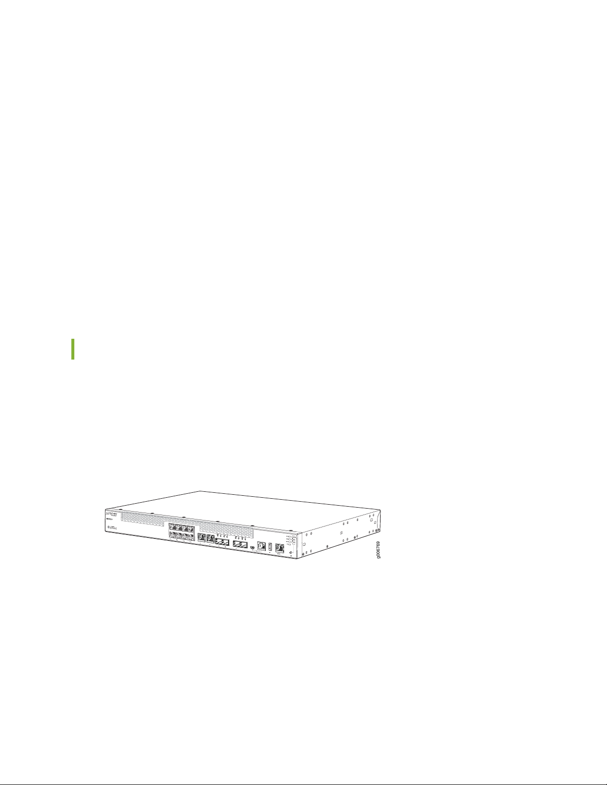
The MX150 provide carrier-grade level of a rich set of Layer 2 and Layer 3 features. The MX150 has eight
1-Gigabit Ethernet network ports, two 1-Gigabit Ethernet RJ-45 ports that can be used as either access
ports or as uplink ports, two SFP ports, two SFP+ ports, and one management port. The MX150 has a 1 U
form factor and is shipped with built-in fans and power supply.
Figure 1: MX150 Port Panel
The MX150 can be used as:
An integrated branch router.
•
A secure router for distributed enterprises.
•
Page 18
System Software
The MX150 use the Junos OS CLI. You can manage the device by using the Junos CLI, accessible through
the console on the device.
MX150 Chassis
IN THIS SECTION
Chassis Physical Specifications for an MX150 | 18
Front Panel of an MX150 | 18
Rear Panel of an MX150 | 20
18
Chassis Status LEDs on MX150 | 20
Network Port and Uplink Port LEDs on MX150 | 22
Management Port LEDs on MX150 | 24
Chassis Physical Specifications for an MX150
MX150 chassis is a rigid sheet-metal structure that houses the hardware components. Table 3 on page 18
summarizes the physical specifications of the MX150 chassis.
Table 3: Physical Specifications for the MX150 Chassis
WeightDepthWidthHeightProduct SKU
9.4 lb (4.3 kg)12 in. (30.5 cm)17.36 in. (44.1 cm)1.72 in. (4.3 cm)MX150
Front Panel of an MX150
The front panel of an MX150 consists of the following components:
Page 19
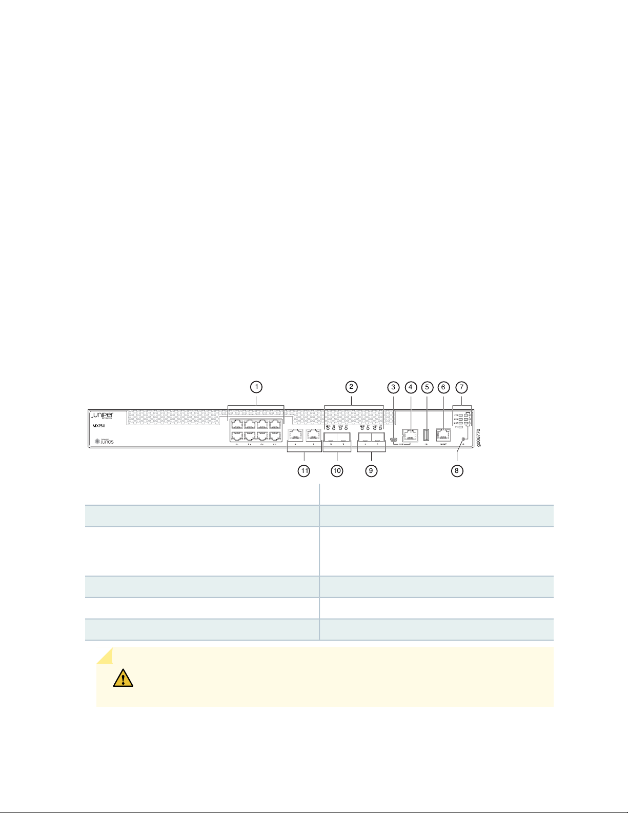
Eight 1-Gigabit Ethernet network ports
g006770
3 4 5 6 7
11 89
1 2
10
•
Two 1-Gigabit Ethernet RJ-45 access ports or uplink ports
•
Two 1-Gigabit SFP ports
•
Two 1/10-Gigabit SFP+ ports
•
Link (LINK) and status (ST) LEDs for SFP and SFP+ ports
•
1 Mini-USB Type-B console port
•
1 RJ-45 console port
•
1 USB port
•
1-Gigabit management port
•
4 system status LEDs
•
3 port parameter LEDs
•
1 Mode button
•
19
Figure 2: MX150 Front Panel Components
Mini-USB console port
6—1-Gigabit management (mgmt) port
7—1— system status LEDs and port parameter LEDs1-Gigabit Ethernet RJ-45 network ports
8—2— Mode buttonLink and Status LEDs for SFP and SFP+ ports
9—3— Port: 0 and 1 support SFP (1G) and SFP+(10G). In
Junos CLI, these ports are shown as xe-0/0/12 and
xe-0/0/13, respectively.
10—4— Port: 10 and 11 support SFP only;Console (CON) port
11—5— 1-Gigabit Ethernet RJ-45 network or uplink portsUSB port
CAUTION: Do not use the Reset button to restart the power sequence unless under
the direction of Juniper Networks Technical Assistance Center (JTAC).
Page 20
SEE ALSO
Prevention of Electrostatic Discharge Damage | 130
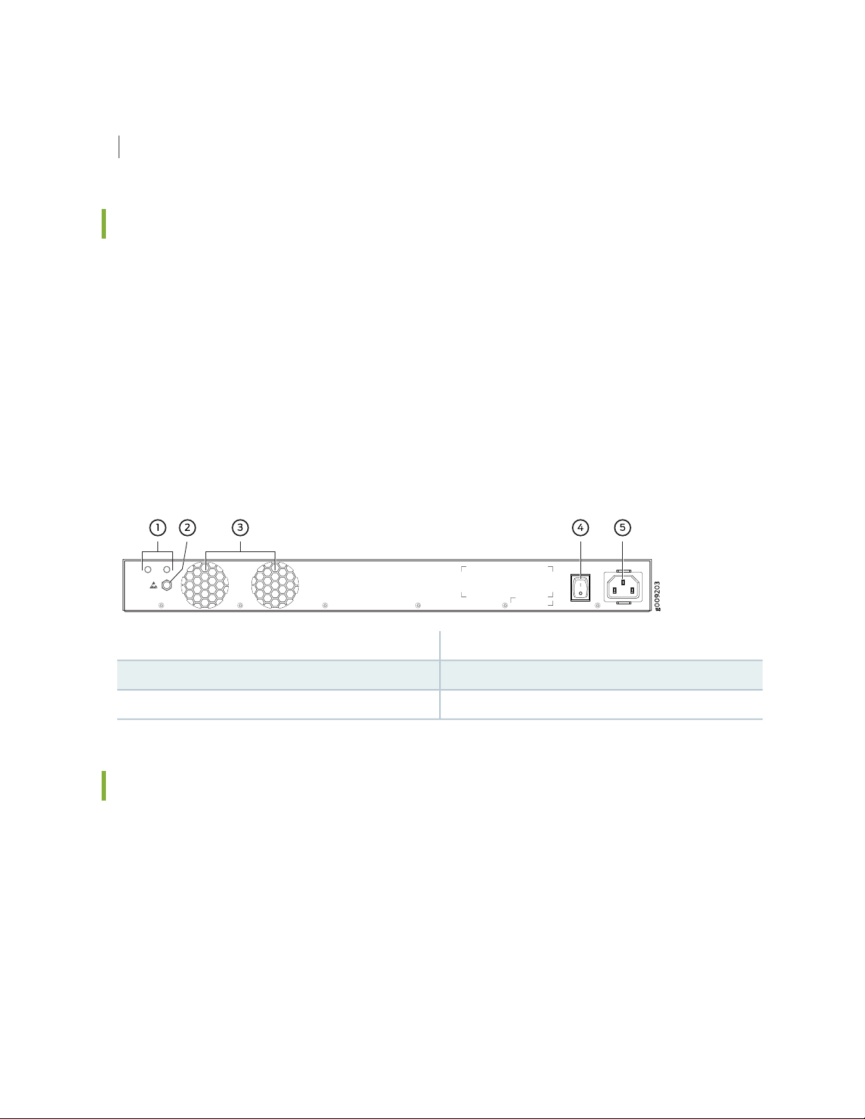
Rear Panel of an MX150
The rear panel of the MX150 consists of the following components (see Figure 3 on page 20):
Ground area
•
Electrostatic discharge (ESD) point
•
Exhaust vents
•
Power switch
•
AC power cord inlet
•
20
Figure 3: MX150 Rear Panel
4—1— Power switchGround area
5—2— AC power cord inletElectrostatic discharge (ESD) point
3—Exhaust vents
Chassis Status LEDs on MX150
The front panel of an MX150 has chassis status LEDs (labeled ALM, SYS, MST and PH), next to the MGMT
port (see Figure 4 on page 21).
Page 21
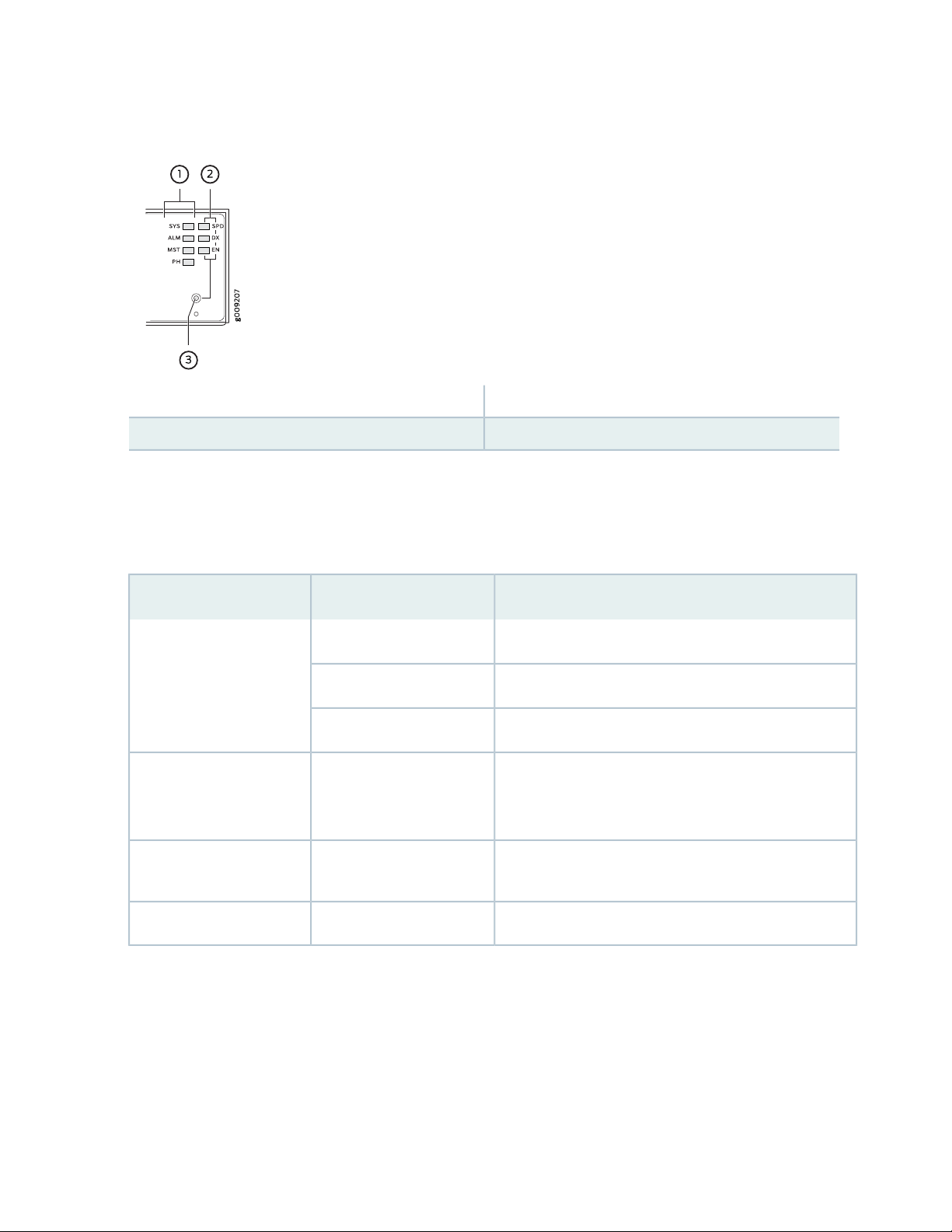
Figure 4: Chassis Status LEDs in an MX150
3—1— Mode buttonChassis status LEDs (ALM, SYS, MST, and PH)
2—Port parameter LEDs (SPD, DX, and EN)
Table 4 on page 21 describes the chassis status LEDs on an MX150, their colors and states, and the status
they indicate. You can view the colors of the four LEDs remotely through the CLI by issuing the operational
mode command show chassis craft-interface.
21
Table 4: Chassis Status LEDs in an MX150
State and DescriptionColorLED Label
There is no alarm or the device is halted.UnlitALM (Alarm)
There is a major alarm.Red
There is a minor alarm.Amber
GreenSYS (System)
GreenMST (Primary)
On steadily—Junos OS has been loaded on the device.
•
Blinking—The device is booting.
•
Off—The device is powered off or is halted.
•
On steadily—The device is functioning normally.
•
Off—The device is powered off or is halted.
•
This LED is not used. So, the status of this LED is off.UnlitPH
A major alarm (red) indicates a critical error condition that requires immediate action.
A minor alarm (amber) indicates a noncritical condition that requires monitoring or maintenance. A minor
alarm left unchecked might cause interruption in service or performance degradation.
All three LEDs can be lit simultaneously.
Page 22
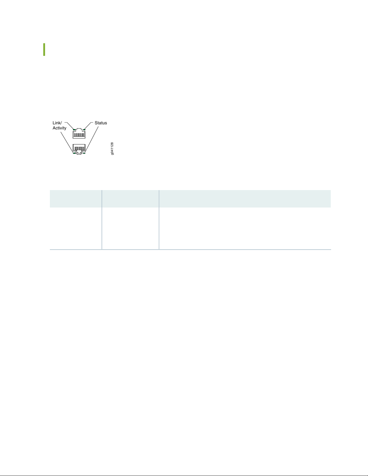
Network Port and Uplink Port LEDs on MX150
g041128
Link/
Activity
Status
Each network port and uplink port on the front panel of an MX150 has two LEDs that indicate link activity
and port status (see Figure 5 on page 22).
Figure 5: LEDs on the Network Port
Table 5 on page 22 describes the link activity of the LED.
Table 5: Link activity LED on the Network Ports and Uplink Ports in MX150
22
State and DescriptionColorLED
GreenLink activity
Blinking—The port and the link are active, and there is link activity.
•
On steadily—The port and the link are active, but there is no link
•
activity.
Off—The port is not active.
•
Figure 6 on page 23 shows the LEDs that indicate the status of one of the three port parameters—speed,
duplex mode, and administrative status. Use the Mode button on the far right side of the front panel to
display the status LED for the different port parameters. You can tell which port parameter (speed, duplex
mode, or administrative status) is indicated by the ST LED by looking at which port parameter LED (SPD,
DX, or EN) is lit.
Page 23
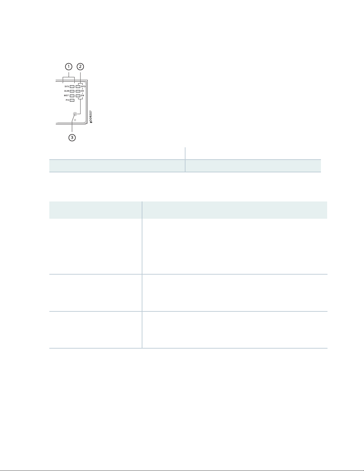
Figure 6: Port Parameter LEDs of an MX150
3—1— Mode buttonChassis status LEDs (ALM, SYS, MST, and PH)
2—Port parameter LEDs (SPD, DX, and EN)
Table 6 on page 23 describes the port parameters LED.
Table 6: Port Parameter LED on the Network Ports and Uplink Ports in MX150
23
State and DescriptionPort Parameter LED
SPD (speed)
DX (duplex mode)
EN (administrative status)
Indicates the speed. The speed indicators for network ports and uplink ports
are:
One blink per second—10 Mbps
•
Two blinks per second—100 Mbps
•
Three blinks per second—1000 Mbps
•
Indicates the duplex mode. The status indicators are:
On steadily—Port is set to full-duplex mode.
•
Off—Port is set to half-duplex mode.
•
Indicates the administrative status. The status indicators are:
On steadily—Port is administratively enabled.
•
Off—Port is administratively disabled.
•
You can tell which port parameter is indicated by the Status LED on network ports by issuing the operational
mode command show chassis craft-interface.
Page 24
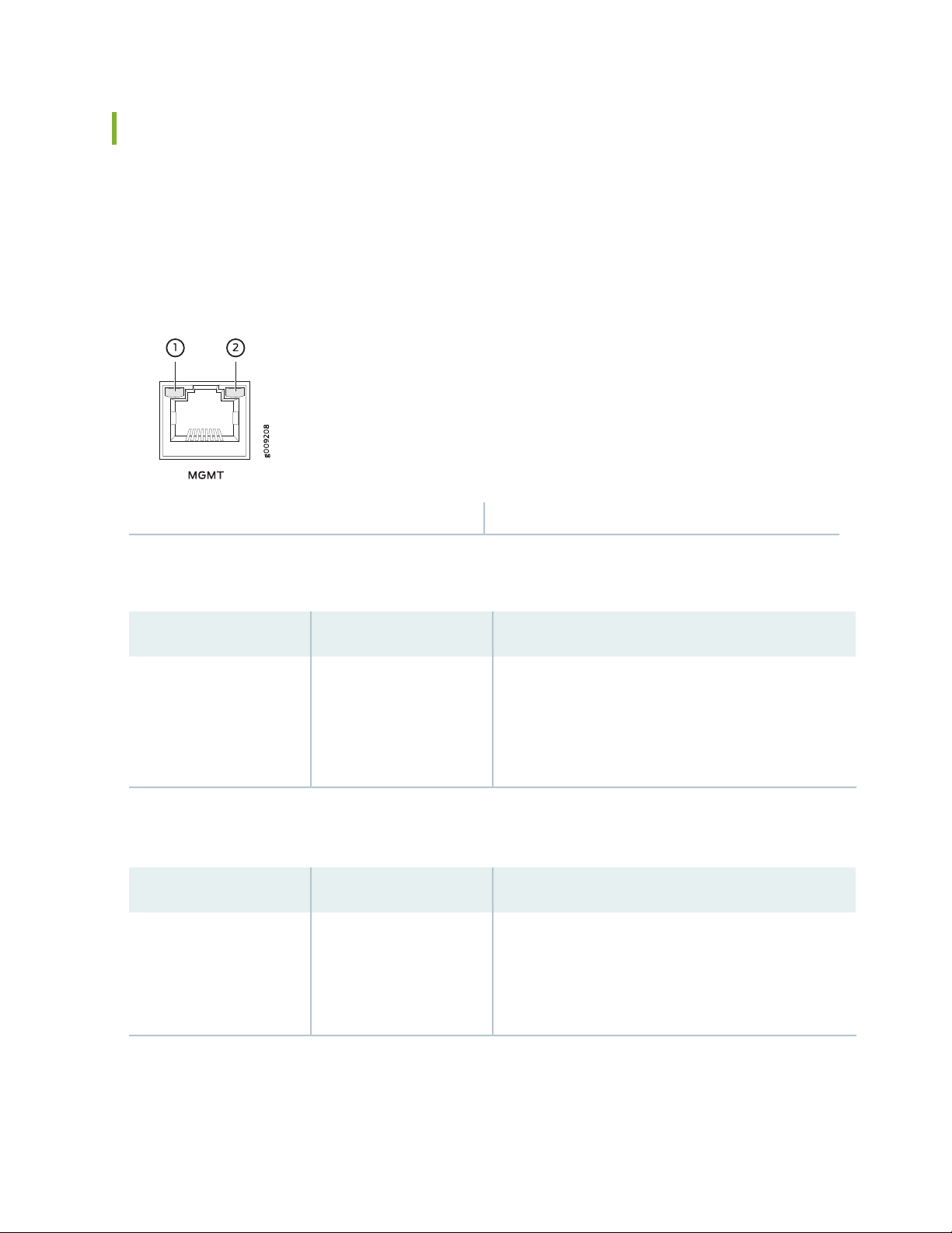
Management Port LEDs on MX150
The management port on the front panel of an MX150 has two LEDs that indicate link activity and port
status (see Figure 7 on page 24).
Figure 7: LEDs on the Management Port of an MX150
24
2—1— StatusLink activity
Table 7 on page 24 describes the Link activity LED.
Table 7: Link activity LED on the Management Port of an MX150
State and DescriptionColorLED
GreenLink activity
Blinking—The port and the link are active, and there is
•
link activity.
On steadily—The port and the link are active, but there
•
is no link activity.
Off—The port is not active.
•
Table 8 on page 24 describes the status LED.
Table 8: Status LED on the Management Port of an MX150
State and DescriptionColorLED
GreenStatus
Indicates the speed. The speed indicators are:
One blink per second—10 Mbps
•
Two blinks per second—100 Mbps
•
Three blinks per second—1000 Mbps
•
SEE ALSO
Page 25
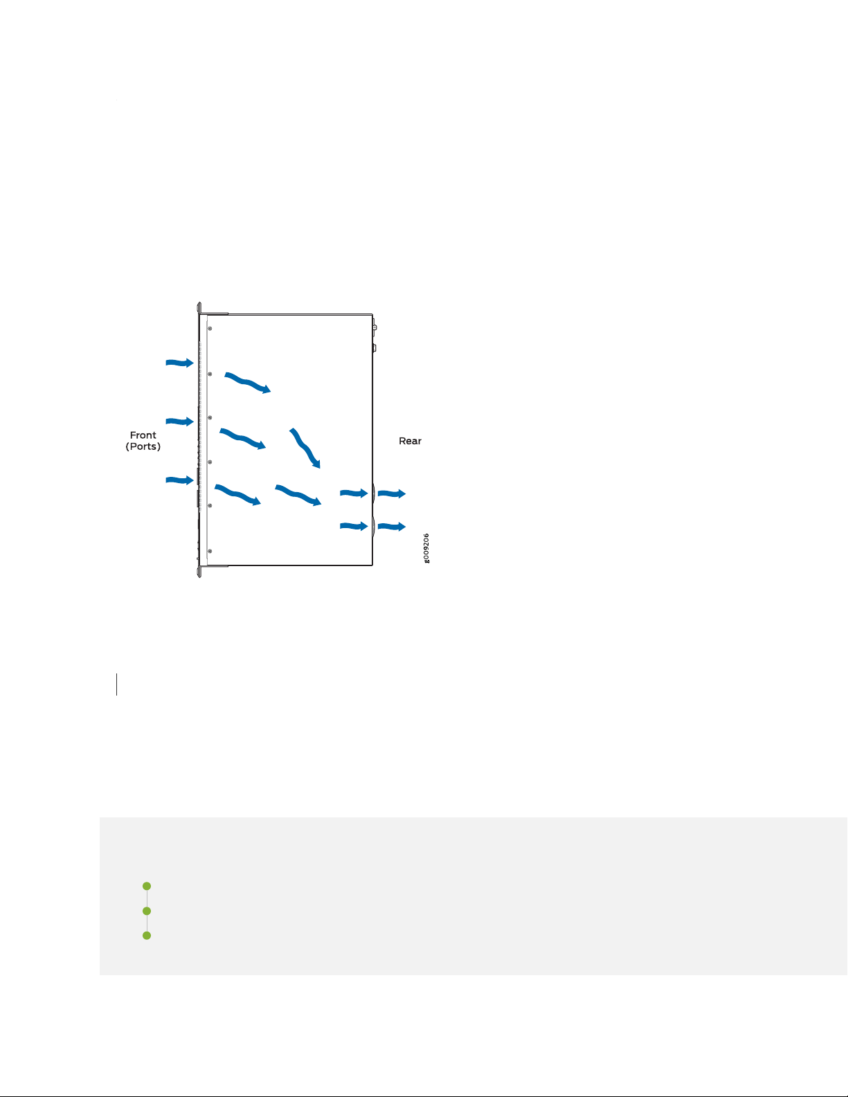
MX150 Cooling System
The MX150 has front-to-back airflow. The air intake to cool the chassis is located at the front of the chassis.
Air is pulled into the chassis and pushed toward the fans, which are built-in. Hot air exhausts from the rear
of the chassis. See Figure 8 on page 25.
Figure 8: Front-to-Back Airflow Through the MX150 Chassis
25
RELATED DOCUMENTATION
Prevention of Electrostatic Discharge Damage | 130
MX150 Power System
IN THIS SECTION
Power Supply in MX150 | 26
AC Power Supply Specifications for an MX150 | 26
AC Power Cord Specifications for an MX150 | 27
Page 26

Power Supply in MX150
The MX150 routers use a fixed, internal AC power supply. The power supply distributes different output
voltages to the device components according to their voltage requirements. The power supply is fixed in
the chassis and is not field-replaceable.
The power supply has a single AC appliance inlet that requires a dedicated AC power feed. The AC power
cord inlet is on the rear panel of the device.
SEE ALSO
Connecting AC Power to an MX150 | 64
AC Power Supply Specifications for an MX150
26
Table 9 on page 26 describes the AC power specifications for an MX150.
Table 9: AC Power Specifications for an MX150
SpecificationItem
AC input voltage
SEE ALSO
General Safety Guidelines and Warnings | 94
General Electrical Safety Guidelines and Warnings | 129
Operating range:
100 through 240 VAC
•
50–60 Hz nominalAC input line frequency
3 A at 240 VACAC input current rating
140 WMaximum power consumption
Page 27

AC Power Cord Specifications for an MX150
A detachable AC power cord is supplied with the AC power supplies. The coupler is type C13 as described
by International Electrotechnical Commission (IEC) standard 60320. The plug at the male end of the power
cord fits into the power source outlet that is standard for your geographical location.
CAUTION: The AC power cord provided with each power supply is intended for use
with that power supply only and not for any other use.
NOTE: In North America, AC power cords must not exceed 4.5 meters in length, to comply with
National Electrical Code (NEC) Sections 400-8 (NFPA 75, 5-2.2) and 210-52 and Canadian
Electrical Code (CEC) Section 4-010(3). The cords supplied with the switch are in compliance.
27
Table 10 on page 27 gives the AC power cord specifications for the countries and regions listed in the
table.
Table 10: AC Power Cord Specifications
Juniper Model NumberPlug StandardsElectrical SpecificationsCountry/Region
CBL-EX-PWR-C13-ARIRAM 2073 Type RA/3250 VAC, 10 A, 50 HzArgentina
250 VAC, 10 A, 50 HzAustralia
SAA/3
Switzerland, and United
Kingdom)
CBL-EX-PWR-C13-AUAS/NZZS 3112 Type
CBL-EX-PWR-C13-BRNBR 14136 Type BR/3250 VAC, 10 A, 50 HzBrazil
CBL-EX-PWR-C13-CHGB 1002-1996 Type PRC/3250 VAC, 10 A, 50 HzChina
CBL-EX-PWR-C13-EUCEE (7) VII Type VIIG250 VAC, 10 A, 50 HzEurope (except Italy,
CBL-EX-PWR-C13-INIS 1293 Type IND/3250 VAC, 10 A, 50 HzIndia
Japan
CBL-EX-PWR-C13-ILSI 32/1971 Type IL/3G250 VAC, 10 A, 50 HzIsrael
CBL-EX-PWR-C13-ITCEI 23-16 Type I/3G250 VAC, 10 A, 50 HzItaly
CBL-EX-PWR-C13-JPSS-00259 Type VCTF125 VAC, 12 A, 50 Hz or 60
Hz
Page 28
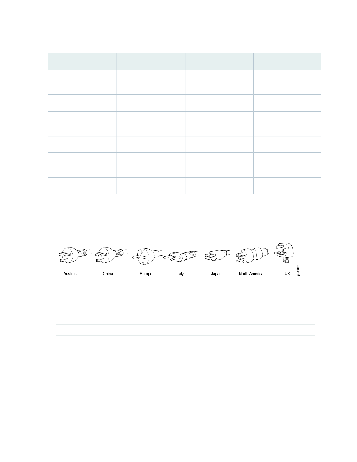
Table 10: AC Power Cord Specifications (continued)
28
Juniper Model NumberPlug StandardsElectrical SpecificationsCountry/Region
Korea
Hz
250 VAC, 10 A, 50 HzSouth Africa
ZA/13
Taiwan
50 Hz
CBL-EX-PWR-C13-KRCEE (7) VII Type VIIGK250 VAC, 10 A, 50 Hz or 60
CBL-EX-PWR-C13-USNEMA 5-15 Type N5-15125 VAC, 13 A, 60 HzNorth America
CBL-EX-PWR-C13-SASABS 164/1:1992 Type
CBL-EX-PWR-C13-SZSEV 6534-2 Type 12G250 VAC, 10 A, 50 HzSwitzerland
CBL-EX-PWR-C13-TWNEMA 5-15P Type N5-15P125 VAC, 11 A and 15 A,
CBL-EX-PWR-C13-UKBS 1363/A Type BS89/13250 VAC, 10 A, 50 HzUnited Kingdom
Figure 9 on page 28 illustrates the plug on the power cord for some of the countries or regions listed in
Table 10 on page 27.
Figure 9: AC Plug Types
SEE ALSO
General Safety Guidelines and Warnings | 94
General Electrical Safety Guidelines and Warnings | 129
Prevention of Electrostatic Discharge Damage | 130
Page 29

2
CHAPTER
Site Planning, Preparation, and
Specifications
Site Preparation Checklist for MX150 | 30
MX150 Site Guidelines and Requirements | 32
MX150 Management and Console Port Specifications and Pinouts | 38
MX150 Network Cable and Transceiver Planning | 43
Page 30

Site Preparation Checklist for MX150
The checklist in Table 11 on page 30 summarizes the tasks you need to perform when preparing a site for
MX150 router installation.
Table 11: Site Preparation Checklist
DatePerformed byFor More InformationItem or Task
Environment
30
Verify that environmental factors such as
temperature and humidity do not exceed
device tolerances.
Power
Measure distance between external power
sources and device installation site.
Locate sites for connection of system
grounding.
Calculate the power consumption and
requirements.
Hardware Configuration
Choose the number of devices you want to
install.
Rack or Cabinet
“Environmental Requirements and
Specifications for an MX150” on
page 33
“AC Power Supply Specifications
for an MX150” on page 26
“MX150 Router Overview” on
page 16
Verify that your rack or cabinet meets the
minimum requirements for the installation
of the device.
Plan rack or cabinet location, including
required space clearances.
“Rack Requirements for an
MX150” on page 37
“Cabinet Requirements for an
MX150” on page 36
“Clearance Requirements for
Airflow and Hardware
Maintenance for an MX150” on
page 34
Page 31

Table 11: Site Preparation Checklist (continued)
Secure the rack or cabinet to the floor and
building structure.
Desk
31
DatePerformed byFor More InformationItem or Task
Verify that the desk meets the minimum
requirements for the installation of the
device.
Verify that there is appropriate clearance in
your selected location.
Wall
Verify that there is appropriate clearance in
your selected location.
Cables
Acquire cables and connectors:
Determine the number of cables needed
•
based on your planned configuration.
Review the maximum distance allowed
•
for each cable. Choose the length of cable
based on the distance between the
hardware components being connected.
“Requirements for Mounting an
MX150 on a Desktop or Other
Level Surface” on page 35
“Clearance Requirements for
Airflow and Hardware
Maintenance for an MX150” on
page 34
“Clearance Requirements for
Airflow and Hardware
Maintenance for an MX150” on
page 34
Plan the cable routing and management.
RELATED DOCUMENTATION
General Safety Guidelines and Warnings | 94
MX150 Installation Overview | 52
Mounting an MX150 | 55
Page 32

MX150 Site Guidelines and Requirements
IN THIS SECTION
General Site Guidelines | 32
Site Electrical Wiring Guidelines | 32
Environmental Requirements and Specifications for an MX150 | 33
Clearance Requirements for Airflow and Hardware Maintenance for an MX150 | 34
Requirements for Mounting an MX150 on a Desktop or Other Level Surface | 35
Cabinet Requirements for an MX150 | 36
Rack Requirements for an MX150 | 37
32
General Site Guidelines
Efficient device operation requires proper site planning and maintenance and proper layout of the equipment,
rack or cabinet (if used), and wiring closet.
To plan and create an acceptable operating environment for your device and prevent environmentally
caused equipment failures:
Keep the area around the chassis free from dust and conductive material, such as metal flakes.
•
Follow prescribed airflow guidelines to ensure that the cooling system functions properly and that
•
exhaust from other equipment does not blow into the intake vents of the device.
Follow the prescribed electrostatic discharge (ESD) prevention procedures to prevent damaging the
•
equipment. Static discharge can cause components to fail completely or intermittently over time.
Install the device in a secure area, so that only authorized personnel can access the device.
•
Site Electrical Wiring Guidelines
Table 12 on page 33 describes the factors you must consider while planning the electrical wiring at your
site.
Page 33

WARNING: You must provide a properly grounded and shielded environment and use
electrical surge-suppression devices.
Table 12: Site Electrical Wiring Guidelines
Site Wiring
Factor
Guidelines
33
Signaling
limitations
Radio
frequency
interference
Electromagnetic
compatibility
If your site experiences any of the following problems, consult experts in electrical surge suppression
and shielding:
Improperly installed wires cause radio frequency interference (RFI).
•
Damage from lightning strikes occurs when wires exceed recommended distances or pass between
•
buildings.
Electromagnetic pulses (EMPs) caused by lightning damage unshielded conductors and electronic
•
devices.
To reduce or eliminate RFI from your site wiring, do the following:
Use a twisted-pair cable with a good distribution of grounding conductors.
•
If you must exceed the recommended distances, use a high-quality twisted-pair cable with one
•
ground conductor for each data signal when applicable.
If your site is susceptible to problems with electromagnetic compatibility (EMC), particularly from
lightning or radio transmitters, seek expert advice.
Some of the problems caused by strong sources of electromagnetic interference (EMI) are:
Destruction of the signal drivers and receivers in the device
•
Electrical hazards as a result of power surges conducted over the lines into the equipment
•
Environmental Requirements and Specifications for an MX150
The MX150 must be installed in a rack or cabinet. It must be housed in a dry, clean, well-ventilated, and
temperature-controlled environment.
Follow these environmental guidelines:
The site must be as dust-free as possible, because dust can clog air intake vents and filters, reducing the
•
efficiency of the device cooling system.
Page 34

Maintain ambient airflow for normal operation of the device. If the airflow is blocked or restricted, or if
•
the intake air is too warm, the device might overheat, leading to the device temperature monitor shutting
down the device to protect the hardware components.
Table 13 on page 34 provides the required environmental conditions for normal operation of the MX150.
Table 13: MX150 Environmental Tolerances
ToleranceDescription
No performance degradation up to 6000 feet (1828 meters) at 86° F (30° C)Altitude
34
Relative humidity
Temperature
SEE ALSO
MX150 Installation Overview | 52
Normal operation ensured in relative humidity range of 5% through 90%,
noncondensing
Normal operation ensured in temperature range of 32° F through 122° F
(0° C through 50° C)
Complies with Zone 4 earthquake requirements as per GR-63, Issue 4Seismic
Clearance Requirements for Airflow and Hardware Maintenance for an MX150
When planning the site for installing an MX150, you must allow sufficient clearance around the installed
chassis (see Figure 10 on page 35).
Page 35

Figure 10: Clearance Requirements for Airflow and Hardware Maintenance for an MX150
35
For the cooling system to function properly, the airflow around the chassis must be unrestricted. See
•
“MX150 Cooling System” on page 25 for more information about the airflow through the chassis.
If you are mounting an MX150 in a rack or cabinet with other equipment, ensure that the exhaust from
•
other equipment does not blow into the intake vents of the chassis.
Leave at least 24 in. (61 cm) both in front of and behind the MX150. For service personnel to remove
•
and install hardware components, you must leave adequate space at the front and back of the MX150.
NEBS GR-63 recommends that you allow at least 30 in. (76.2 cm) in front of the rack or cabinet and
24 in. (61 cm) behind the rack or cabinet.
SEE ALSO
Rack-Mounting and Cabinet-Mounting Warnings | 106
Requirements for Mounting an MX150 on a Desktop or Other Level Surface
You can install the MX150 on a desktop or other such level surface, by attaching the four rubber feet
(provided) to the bottom of the chassis.
Page 36

When choosing a location, allow at least 6 in. (15.2 cm) of clearance between the front and back of the
chassis and adjacent equipment or walls.
Ensure that the desktop or other level surface on which the device is installed is stable and securely
supported.
Cabinet Requirements for an MX150
You can mount the MX150 in an enclosure or cabinet that contains a four-post 19-in. open rack as defined
in Cabinets, Racks, Panels, and Associated Equipment (document number EIA-310-D) published by the
Electronics Industry Association.
Cabinet requirements consist of:
Cabinet size and clearance
•
Cabinet airflow requirements
•
36
Table 14 on page 36 provides the cabinet requirements and specifications for the MX150.
Table 14: Cabinet Requirements for the MX150
GuidelinesCabinet Requirement
Cabinet size and clearance
Cabinet airflow requirements
The minimum cabinet size for accommodating an MX150 is 36 in. (91.4 cm)
deep. Large cabinets improve airflow and reduce the chance of overheating.
When you mount the switch in a cabinet, ensure that ventilation through the
cabinet is sufficient to prevent overheating.
Ensure that the cool air supply you provide through the cabinet adequately
•
dissipates the thermal output of the switch (or switches).
Ensure that the cabinet allows the chassis hot exhaust air to exit the cabinet
•
without recirculating into the switch. An open cabinet (without a top or
doors) that employs hot air exhaust extraction from the top allows the best
airflow through the chassis. If the cabinet contains a top or doors,
perforations in these elements assist with removing the hot air exhaust.
Install the switch in the cabinet in a way that maximizes the open space
•
on the side of the chassis that has the hot air exhaust.
Route and dress all cables to minimize the blockage of airflow to and from
•
the chassis.
Ensure that the spacing of rails and adjacent cabinets allows for the proper
•
clearance around the switch and cabinet.
A cabinet larger than the minimum required provides better airflow and
•
reduces the chance of overheating.
Page 37

Rack Requirements for an MX150
You can mount the MX150 on two-post racks or four-post racks.
Rack requirements consist of:
Rack type
•
Mounting bracket hole spacing
•
Rack size and strength
•
Rack connection to the building structure
•
Table 15 on page 37 provides the rack requirements and specifications for the MX150.
Table 15: Rack Requirements and Specifications for the MX150
GuidelinesRack Requirement
37
Rack type
Mounting bracket
hole spacing
Rack size and strength
Use a two-post rack or a four-post rack. You can mount the device on any two-post or
four-post rack that provides bracket holes or hole patterns spaced at 1 U (1.75 in. or 4.45 cm)
increments and that meets the size and strength requirements to support the weight.
A U is the standard rack unit defined in Cabinets, Racks, Panels, and Associated Equipment
(document number EIA-310–D) published by the Electronics Industry Association
(http://www.ecianow.org/standards-practices/standards/).
The rack must meet the strength requirements to support the weight of the chassis.
The holes in the mounting brackets are spaced at 1 U (1.75 in. or 4.45 cm), so that the device
can be mounted in any rack that provides holes spaced at that distance.
Ensure that the rack complies with the standard defined for 19-in. rack as defined in Cabinets,
•
Racks, Panels, and Associated Equipment (document number EIA-310–D) published by the
Electronics Industry Association (http://www.ecianow.org/standards-practices/standards/).
Ensure that the rack rails are spaced widely enough to accommodate the device chassis'
•
external dimensions of 1.72 in. (4.3 cm) height, 17.36 in. (44.1 cm) width, and 12 in. (30.5 cm)
depth. The 19-in. rack brackets dimensions are 0.82 in. (2.1 cm) wide, 1.72 in. (4.3 cm)
height, and 2.1 in. (5.4 cm) depth. The 23-in. rack brackets dimensions are 3.3 in. (8.4 cm)
wide, 1.72 in. (4.3 cm) height, and 8.5 in. (21.6 cm) depth.
The rack must be strong enough to support the weight of the device.
•
Ensure that the spacing of rails and adjacent racks allows for the proper clearance around
•
the device and rack.
Rack connection to
building structure
Secure the rack to the building structure.
•
If earthquakes are a possibility in your geographical area, secure the rack to the floor.
•
Secure the rack to the ceiling brackets as well as wall or floor brackets for maximum stability.
•
Page 38

One pair of mounting brackets for mounting the device on two posts of a rack is supplied with each device.
For mounting the device on four posts of a rack or cabinet, you can order a four-post rack-mount kit
separately.
SEE ALSO
Rack-Mounting and Cabinet-Mounting Warnings | 106
Mounting an MX150 on Two Posts in a Rack | 57
Mounting an MX150 on Four Posts in a Rack or Cabinet | 59
MX150 Management and Console Port Specifications and Pinouts
38
IN THIS SECTION
Mini-USB Type-B Console Port Specifications for an MX150 | 38
Console Port Connector Pinouts for MX150 | 39
USB Port Specifications for an MX150 | 40
Network Port Connector Pinout Information for an MX150 | 41
RJ-45 to DB-9 Serial Port Adapter Pinout Information for an MX150 | 42
Mini-USB Type-B Console Port Specifications for an MX150
The MX150 has two console ports: an RJ-45 port, and a Mini-USB port.
By default, the RJ-45 port is set as the active console port. It can display all the early boot and low-level
message output and you can access the device through this port in the debugger prompt.
The Mini-USB port is the passive console port. You can change the status of the port to active or passive
using the port-type configuration statement. See Configuring the Console Port Type (CLI Procedure).
The Mini-USB console port uses a Mini-B plug (5-pin) connector to connect to a console management
device. The default baud rate for the console port is 9600 baud.
Page 39

Table 16 on page 39 provides the pinout information of the Mini-USB Type-B console port.
Table 16: Mini-USB Type-B Console Port Pinout Information for MX150
DescriptionSignalPin
+5 VDCVCC1
Data -D-2
Data +D+3
N/C, GND, or used as an attached device presence indicatorN/CX
GroundGND4
39
SEE ALSO
MX150 Router Overview | 16
Configuring the Console Port Type (CLI Procedure)
Console Port Connector Pinouts for MX150
The console port (labeled CON) is an RS-232 serial interface that uses an RJ-45 connector to connect to
a console management device. The default baud rate for the console port is 9600 baud.
Table 17 on page 39 provides the pinout information for the RJ-45 console connector. An RJ-45 cable
and RJ-45 to DB-9 adapter are supplied with the MX150 device.
NOTE: If your laptop or PC does not have a DB-9 plug connector pin and you want to connect
your laptop or PC directly to an MX150 device, use a combination of the RJ-45 cable and RJ-45
to DB-9 adapter supplied with the device and a USB to DB-9 plug adapter. You must provide
the USB to DB-9 plug adapter.
Table 17: Console Port Connector Pinouts for the MX150
DescriptionSignalPin
Request to sendRTS Output1
Page 40

Table 17: Console Port Connector Pinouts for the MX150 (continued)
40
DescriptionSignalPin
Data terminal readyDTR Output2
Transmit dataTxD Output3
Signal groundSignal Ground4
Signal groundSignal Ground5
Receive dataRxD Input6
Data carrier detectDCD Input7
Clear to sendCTS Input8
SEE ALSO
Connecting an MX150 to a Management Console | 65
USB Port Specifications for an MX150
The following Juniper Networks USB flash drives have been tested and are officially supported for the
USB port in the MX150:
RE-USB-1G-S—1-gigabyte (GB) USB flash drive
•
RE-USB-2G-S—2-GB USB flash drive
•
RE-USB-4G-S—4-GB USB flash drive
•
CAUTION: Any USB memory product not listed as supported for the MX150 has not
been tested by Juniper Networks. The use of any unsupported USB memory product
could expose your device to unpredictable behavior. Juniper Networks Technical
Assistance Center (JTAC) can provide only limited support for issues related to
unsupported hardware. We strongly recommend that you use only supported USB
flash drives.
Page 41

CAUTION: Remove the USB flash drive before upgrading Junos OS or rebooting the
MX150. Failure to do so could expose your device to unpredictable behavior.
NOTE: Executing the request system snapshot CLI command on the MX150 requires an external
USB flash drive with at least 4 GB of free space. We recommend using the RE-USB-4G-S flash
drive.
NOTE: USB flash drives used with the MX150 must support USB 2.0 or later.
41
SEE ALSO
Front Panel of an MX150 | 18
Network Port Connector Pinout Information for an MX150
A network port on an MX150 uses an RJ-45 connector to connect to a device.
The port uses an autosensing RJ-45 connector to support a 10/100/1000Base-T connection. Two LEDs
on the port indicate link activity on the port and the port status. See “Network Port and Uplink Port LEDs
on MX150” on page 22.
Table 18 on page 41 provides the pinout information for the RJ-45 connector. An RJ-45 cable, with a
connector attached, is supplied with the switch.
Table 18: Network Port Connector Pinout Information for the MX150
DescriptionSignalPin
TRP1+1
Transmit/receive data pair 1
Negative Vport (in PoE models)
TRP1-2
Transmit/receive data pair 1
Negative Vport (in PoE models)
Page 42

Table 18: Network Port Connector Pinout Information for the MX150 (continued)
DescriptionSignalPin
42
SEE ALSO
MX150 Router Overview | 16
TRP2+3
TRP2-6
Transmit/receive data pair 2
Positive Vport (in PoE models)
Transmit/receive data pair 3TRP3+4
Transmit/receive data pair 3TRP3-5
Transmit/receive data pair 2
Positive Vport (in PoE models)
Transmit/receive data pair 4TRP4+7
Transmit/receive data pair 4TRP4-8
RJ-45 to DB-9 Serial Port Adapter Pinout Information for an MX150
The console port is an RS-232 serial interface that uses an RJ-45 connector to connect to a management
device such as a PC or a laptop. If your laptop or PC does not have a DB-9 plug connector pin and you
want to connect your laptop or PC to an MX150, use a combination of the RJ-45 to DB-9 socket adapter
supplied with the switch along with a USB to DB-9 plug adapter.
Table 19 on page 42 provides the pinout information for the RJ-45 to DB-9 serial port adapter.
Table 19: RJ-45 to DB-9 Serial Port Adapter Pinout Information
SignalDB-9 PinSignalRJ-45 Pin
CTS8RTS1
DSR6DTR2
RXD2TXD3
Page 43

Table 19: RJ-45 to DB-9 Serial Port Adapter Pinout Information (continued)
SEE ALSO
Connecting an MX150 to a Management Console | 65
43
SignalDB-9 PinSignalRJ-45 Pin
GND5GND4
TXD3RXD6
DTR4DSR7
RTS7CTS8
MX150 Network Cable and Transceiver Planning
IN THIS SECTION
Pluggable Transceivers Supported on MX150 | 43
SFP+ Direct Attach Copper Cables for MX150 | 44
Cable Specifications for Console and Management Connections for the MX150 | 46
Understanding MX150 Fiber-Optic Cable Signal Loss, Attenuation, and Dispersion | 47
Calculating the Fiber-Optic Cable Power Budget for an MX150 | 48
Calculating the Fiber-Optic Cable Power Margin for an MX150 | 49
Pluggable Transceivers Supported on MX150
Uplink ports on MX150 support SFP and SFP+ transceivers. This topic describes the optical interfaces
supported for those transceivers. It also lists the copper interface supported for the SFP transceivers.
Page 44

NOTE: We recommend that you use only optical transceivers and optical connectors purchased
from Juniper Networks with your Juniper Networks device.
CAUTION: If you face a problem running a Juniper Networks device that uses a
third-party optic or cable, the Juniper Networks Technical Assistance Center (JTAC)
can help you diagnose the source of the problem. Your JTAC engineer might recommend
that you check the third-party optic or cable and potentially replace it with an equivalent
Juniper Networks optic or cable that is qualified for the device.
NOTE: You can use the Hardware Compatibility Tool to find information about the pluggable
transceivers supported on your Juniper Networks device.
The list of supported transceivers for the MX Series is located at
https://pathfinder.juniper.net/hct/category/#catKey=100001&modelType;=All&pf;=MX+Series.
44
SEE ALSO
Front Panel of an MX150 | 18
Installing a Transceiver in an MX150 | 74
Removing a Transceiver from an MX150 | 72
SFP+ Direct Attach Copper Cables for MX150
IN THIS SECTION
Cable Specifications | 45
Standards Supported by These Cables | 45
Page 45

Small form-factor pluggable plus transceiver (SFP+) direct attach copper (DAC) cables, also known as
Twinax cables, are suitable for in-rack connections between servers and switches. They are suitable for
short distances of up to 23 ft, making them ideal for highly cost-effective networking connectivity within
a rack and between adjacent racks.
This topic describes:
Cable Specifications
MX150 routers support SFP+ passive DAC cables. The passive Twinax cable is a straight cable with no
active electronic components. MX150 routers support 1 m, 3 m, and 5 m long SFP+ passive DAC cables.
NOTE: We recommend that you use only SFP+ DAC cables purchased from Juniper Networks
with your Juniper Networks device.
45
CAUTION: If you face a problem running a Juniper Networks device that uses a
third-party optic or cable, the Juniper Networks Technical Assistance Center (JTAC)
can help you diagnose the source of the problem. Your JTAC engineer might recommend
that you check the third-party optic or cable and potentially replace it with an equivalent
Juniper Networks optic or cable that is qualified for the device.
The cables are hot-removable and hot-insertable: You can remove and replace them without powering
off the switch or disrupting switch functions. A cable comprises a low-voltage cable assembly that connects
directly into two SFP+ ports, one at each end of the cable. The cables use high-performance integrated
duplex serial data links for bidirectional communication and are designed for data rates of up to 10 Gbps.
NOTE: You can use the Hardware Compatibility Tool to find information about the cables
supported on your Juniper Networks device.
The list of supported transceivers for the MX Series is located at
https://pathfinder.juniper.net/hct/category/#catKey=100001&modelType;=All&pf;=MX+Series.
Standards Supported by These Cables
The cables comply with the following standards:
SFP mechanical standard SFF-843—see ftp://ftp.seagate.com/sff/SFF-8431.PDF .
•
Page 46

Electrical interface standard SFF-8432—see ftp://ftp.seagate.com/sff/SFF-8432.PDF .
•
SFP+ Multi-Source Alliance (MSA) standards
•
SEE ALSO
Installing a Transceiver in an MX150 | 74
Removing a Transceiver from an MX150 | 72
Cable Specifications for Console and Management Connections for the MX150
Table 20 on page 46 lists the specifications for the cables that connect the MX150 to a management
device.
46
Table 20: Cable Specifications for Console and Management Connections for the MX150
Port on MX150
Device
Console port
Management port
RS-232 (EIA-232) serial
cable
Category 5 cable or
equivalent suitable for
1000BASE-T operation
patch cable and RJ-45 to
DB-9 adapter
patch cable
Maximum
LengthCable SuppliedCable Specification
SEE ALSO
Connecting an MX150 to a Management Console | 65
Device
Receptacle
RJ-452.13 metersOne 2.13-meter-long RJ-45
RJ-452.13 metersOne 2.13-meter-long RJ-45
Page 47

Understanding MX150 Fiber-Optic Cable Signal Loss, Attenuation, and Dispersion
IN THIS SECTION
Signal Loss in Multimode and Single-Mode Fiber-Optic Cables | 47
Attenuation and Dispersion in Fiber-Optic Cable | 47
To determine the power budget and power margin needed for fiber-optic connections, you need to
understand how signal loss, attenuation, and dispersion affect transmission. The MX150 uses various types
of network cable, including multimode and single-mode fiber-optic cables.
47
Signal Loss in Multimode and Single-Mode Fiber-Optic Cables
Multimode fiber is large enough in diameter to allow rays of light to reflect internally (bounce off the walls
of the fiber). Interfaces with multimode optics typically use LEDs as light sources. However, LEDs are not
coherent light sources. They spray varying wavelengths of light into the multimode fiber, which reflects
the light at different angles. Light rays travel in jagged lines through a multimode fiber, causing signal
dispersion. When light traveling in the fiber core radiates into the fiber cladding (layers of lower refractive
index material in close contact with a core material of higher refractive index), higher-order mode loss
occurs. Together, these factors reduce the transmission distance of multimode fiber compared to that of
single-mode fiber.
Single-mode fiber is so small in diameter that rays of light reflect internally through one layer only. Interfaces
with single-mode optics use lasers as light sources. Lasers generate a single wavelength of light, which
travels in a straight line through the single-mode fiber. Compared to multimode fiber, single-mode fiber
has a higher bandwidth and can carry signals for longer distances. It is consequently more expensive.
For information about the maximum transmission distance and supported wavelength range for the types
of single-mode and multimode fiber-optic cables that are connected to the MX150, see “Pluggable
Transceivers Supported on MX150” on page 43. Exceeding the maximum transmission distances can result
in significant signal loss, which causes unreliable transmission.
Attenuation and Dispersion in Fiber-Optic Cable
An optical data link functions correctly provided that modulated light reaching the receiver has enough
power to be demodulated correctly. Attenuation is the reduction in strength of the light signal during
transmission. Passive media components such as cables, cable splices, and connectors cause attenuation.
Although attenuation is significantly lower for optical fiber than for other media, it still occurs in both
Page 48

multimode and single-mode transmission. An efficient optical data link must transmit enough light to
overcome attenuation.
Dispersion is the spreading of the signal over time. The following two types of dispersion can affect signal
transmission through an optical data link:
Chromatic dispersion, which is the spreading of the signal over time caused by the different speeds of
•
light rays.
Modal dispersion, which is the spreading of the signal over time caused by the different propagation
•
modes in the fiber.
For multimode transmission, modal dispersion, rather than chromatic dispersion or attenuation, usually
limits the maximum bit rate and link length. For single-mode transmission, modal dispersion is not a factor.
However, at higher bit rates and over longer distances, chromatic dispersion limits the maximum link length.
An efficient optical data link must have enough light to exceed the minimum power that the receiver
requires to operate within its specifications. In addition, the total dispersion must be within the limits
specified for the type of link in Telcordia Technologies document GR-253-CORE (Section 4.3) and
International Telecommunications Union (ITU) document G.957.
48
When chromatic dispersion is at the maximum allowed, its effect can be considered as a power penalty in
the power budget. The optical power budget must allow for the sum of component attenuation, power
penalties (including those from dispersion), and a safety margin for unexpected losses.
Calculating the Fiber-Optic Cable Power Budget for an MX150
Calculate the link's power budget when planning fiber-optic cable layout and distances to ensure that
fiber-optic connections have sufficient power for correct operation. The power budget is the maximum
amount of power the link can transmit. When you calculate the power budget, you use a worst-case
analysis to provide a margin of error, even though all the parts of an actual system do not operate at the
worst-case levels.
To calculate the worst-case estimate for fiber-optic cable power budget (PB) for the link:
1. Determine values for the link's minimum transmitter power (PT) and minimum receiver sensitivity (PR).
For example, here, (PT) and (PR) are measured in decibels, and decibels are referenced to 1 milliwatt
(dBm).
PT= –15 dBm
PR= –28 dBm
Page 49

NOTE: See the specifications for your transmitter and receiver to find the minimum transmitter
power and minimum receiver sensitivity.
2. Calculate the power budget (PB) by subtracting (PR) from (PT):
–15 dBm – (–28 dBm) = 13 dBm
Calculating the Fiber-Optic Cable Power Margin for an MX150
Calculate the link's power margin when planning fiber-optic cable layout and distances to ensure that
fiber-optic connections have sufficient signal power to overcome system losses and still satisfy the minimum
input requirements of the receiver for the required performance level. The power margin (PM) is the
amount of power available after attenuation or link loss (LL) has been subtracted from the power budget
(PB).
49
When you calculate the power margin, you use a worst-case analysis to provide a margin of error, even
though all the parts of an actual system do not operate at worst-case levels. A power margin (PM) greater
than zero indicates that the power budget is sufficient to operate the receiver and that it does not exceed
the maximum receiver input power. This means the link will work. A (PM) that is zero or negative indicates
insufficient power to operate the receiver. See the specification for your receiver to find the maximum
receiver input power.
Before you begin to calculate the power margin:
Calculate the power budget. See “Calculating the Fiber-Optic Cable Power Budget for an MX150” on
•
page 48.
To calculate the worst-case estimate for the power margin (PM) for the link:
1. Determine the maximum value for link loss (LL) by adding estimated values for applicable link-loss
factors—for example, use the sample values for various factors as provided in Table 21 on page 49
(here, the link is 2 km long and multimode, and the (PB) is 13 dBm):
Table 21: Estimated Values for Factors Causing Link Loss
Sample Link Loss (LL) Calculation ValuesEstimated Link-Loss ValueLink-Loss Factor
losses
0.5 dBmMultimode—0.5 dBmHigher-order mode
0 dBmSingle-mode—None
Page 50

Table 21: Estimated Values for Factors Causing Link Loss (continued)
Sample Link Loss (LL) Calculation ValuesEstimated Link-Loss ValueLink-Loss Factor
50
Modal and chromatic
dispersion
(CRM)
bandwidth and distance is less
than 500 MHz/km
0.5 dBmConnector
0.5 dBmSplice
Multimode—1 dBm/kmFiber attenuation
Single-mode—0.5 dBm/km
0 dBmMultimode—None, if product of
0 dBmSingle-mode—None
This example assumes five connectors. Loss for five
connectors: 5 (0.5 dBm) = 2.5 dBm.
This example assumes two splices. Loss for two
splices: 2 (0.5 dBm) = 1 dBm.
This example assumes the link is 2 km long. Fiber
attenuation for 2 km: 2 km (1 dBm/km) = 2 dBm.
This example assumes the link is 2 km long. Fiber
attenuation for 2 km: 2 km (0.5 dBm/km) = 1 dBm.
1 dBm1 dBmClock Recovery Module
NOTE: For information about the actual amount of signal loss caused by equipment and
other factors, see your vendor documentation for that equipment.
2. Calculate the (PM) by subtracting (LL) from (PB):
PB– LL = P
M
13 dBm – 0.5 dBm [HOL] – 5 (0.5 dBm) – 2 (0.5 dBm) – 2 km (1.0 dBm/km) – 1 dB [CRM] = P
13 dBm – 0.5 dBm – 2.5 dBm – 1 dBm – 2 dBm – 1 dBm = P
M
PM= 6 dBm
The calculated power margin is greater than zero, indicating that the link has sufficient power for
transmission. Also, the power margin value does not exceed the maximum receiver input power. Refer
to the specifications for your receiver to find the maximum receiver input power.
M
Page 51

3
CHAPTER
Initial Installation and Configuration
MX150 Installation Overview | 52
Unpacking and Mounting the MX150 | 52
Connecting the MX150 to Power | 62
Connecting the MX150 to the Network | 65
Performing the Initial Software Configuration for the MX150 | 68
Page 52

MX150 Installation Overview
To install and connect an MX150:
1. Follow instructions in “Unpacking an MX150” on page 53.
2. Mount the MX150 by following instructions appropriate for your site:
“Mounting an MX150 on a Desk or Other Level Surface” on page 56 (using the rubber feet provided)
•
“Mounting an MX150 on Two Posts in a Rack” on page 57 (using the mounting brackets provided)
•
“Mounting an MX150 on Four Posts in a Rack or Cabinet” on page 59 (using the separately orderable
•
four-post rack-mount kit)
3. Follow instructions in “Connecting Earth Ground to an MX150” on page 62.
4. Follow instructions in “Connecting AC Power to an MX150” on page 64.
52
5. Perform initial configuration of the device by following instructions in “Performing the Initial Software
Configuration for the MX150” on page 68.
6. Set the device’s management options by following the appropriate instructions:
Connecting an MX150 to a Management Console on page 65
•
Unpacking and Mounting the MX150
IN THIS SECTION
Unpacking an MX150 | 53
Parts Inventory (Packing List) for an MX150 | 53
Register Products—Mandatory for Validating SLAs | 54
Mounting an MX150 | 55
Mounting an MX150 on a Desk or Other Level Surface | 56
Mounting an MX150 on Two Posts in a Rack | 57
Mounting an MX150 on Four Posts in a Rack or Cabinet | 59
Page 53

Unpacking an MX150
The MX150 is shipped in a cardboard carton, secured with foam packing material. The carton has an
accessory compartment and contains the quick start instructions.
CAUTION: The MX150 is maximally protected inside the shipping carton. Do not
unpack the devices until you are ready to begin installation.
To unpack the device:
1. Open the carton.
2. Pull out the packing material holding the device in place.
3. Verify the parts received against the inventory on the label attached to the carton. See “Parts Inventory
(Packing List) for an MX150” on page 53.
53
4. Save the shipping carton and packing materials in case you need to move or ship the switch later.
Parts Inventory (Packing List) for an MX150
The MX150 is shipped in a cardboard carton, secured with foam packing material. The carton contains an
accessory box.
The device shipment includes a packing list. Check the parts you receive in the device shipping carton
against the items on the packing list. The parts shipped depend on the configuration you order.
If any part on the packing list is missing, contact your customer service representative or contact Juniper
customer care from within the U.S. or Canada by telephone at 1-888-314-5822. For international-dial or
direct-dial options in countries without toll-free numbers, see
https://www.juniper.net/support/requesting-support.html.
Table 22 on page 53 lists the parts and their quantities in the packing list.
Table 22: Packing List for an MX150
QuantityComponent
1Device
Page 54

Table 22: Packing List for an MX150 (continued)
54
QuantityComponent
1AC power cord appropriate for your geographical location
1AC power cord retainer clip
2Mounting brackets
8Mounting screws to attach the mounting brackets to the device chassis
4Rubber feet
1RJ-45 cable and RJ-45 to DB-9 serial port adapter
1Quick Start installation instructions
1Juniper Networks Product Warranty
1End User License Agreement
NOTE: You must provide mounting screws that are appropriate for your rack or cabinet to mount
the chassis on a rack or a cabinet.
SEE ALSO
MX150 Router Overview | 16
Register Products—Mandatory for Validating SLAs
Register all new Juniper Networks hardware products and changes to an existing installed product using
the Juniper Networks website to activate your hardware replacement service-level agreements (SLAs).
Page 55

CAUTION: Register product serial numbers on the Juniper Networks website and
update the installation base data if there is any addition or change to the installation
base or if the installation base is moved. Juniper Networks will not be held accountable
for not meeting the hardware replacement service-level agreement for products that
do not have registered serial numbers or accurate installation base data.
Register your product(s) at https://tools.juniper.net/svcreg/SRegSerialNum.jsp.
Update your installation base at
https://www.juniper.net/customers/csc/management/updateinstallbase.jsp.
Mounting an MX150
Table 23 on page 55 lists the methods you can use to mount an MX150.
55
Table 23: MX150 Mounting Methods
CommentsDevice ModelMounting Method
MX150Desk or other level surface
•
MX150Two-post rack or cabinet
•
MX150Four-post rack or cabinet
•
On a desk or other level surface by using rubber feet provided
with the device.
On two posts in a 19-in. rack or cabinet by using the mounting
brackets.
On four posts in a 19-in. rack or cabinet by using the
•
separately orderable four-post rack-mount kit
On two posts in a 19-in. rack or cabinet by using the
•
two-post rack mounting brackets.
On a wall by using separately orderable wall-mount kitMX150Wall Mounting
The holes in the mounting brackets are placed at 1 U (1.75 in. or 4.45 cm) apart so that the switch can be
mounted in any rack or cabinet that provides holes spaced at that distance.
See the Related Documentation for detailed descriptions of the various rack or cabinet mounting options.
Page 56

Mounting an MX150 on a Desk or Other Level Surface
g006771
You can mount an MX150 on a desk or other level surface by using the four rubber feet that are shipped
with the router. The rubber feet stabilize the chassis.
Before mounting the MX150 on a desk or other level surface:
Verify that the site meets the requirements described in “Site Preparation Checklist for MX150” on
•
page 30.
Place the desk in its permanent location, allowing adequate clearance for airflow and maintenance, and
•
secure it to the building structure.
Read “General Safety Guidelines and Warnings” on page 94, with particular attention to “Chassis Lifting
•
Guidelines for MX150” on page 101.
Ensure that you have the four rubber feet to stabilize the chassis on the a desk or other level surface
•
(provided in the accessory box in the router carton)
To mount an MX150 on a desk or other level surface:
56
1. Remove the device from the shipping carton (see “Unpacking an MX150” on page 53).
2. Turn the chassis upside down on the desk or the level surface where you intend to mount the device.
3. Attach the rubber feet to the bottom of the chassis as shown in Figure 11 on page 56
4. Turn the chassis right side up on the desk or the level surface.
Figure 11: Attaching Rubber Feet to the MX150
SEE ALSO
Clearance Requirements for Airflow and Hardware Maintenance for an MX150 | 34
Page 57

Mounting an MX150 on Two Posts in a Rack
You can mount an MX150 on two posts of a 19-in. rack (either a two-post or a four-post rack).
NOTE: If you need to mount the MX150 in a recessed position on either a two-post rack or a
four-post rack, you can use the 2-in.-recess front brackets provided in the separately orderable
four-post rack-mount kit.
Before mounting an MX150 on two posts in a rack:
Place the rack in its permanent location, allowing adequate clearance for airflow and maintenance, and
•
secure it to the building structure.
Read “General Safety Guidelines and Warnings” on page 94.
•
Remove the router from the shipping carton.
•
57
Ensure that you have the following parts and tools available:
Phillips (+) screwdriver, number 2
•
Two mounting brackets and eight mounting screws (provided in the accessory box shipped with the
•
router)
Screws to secure the chassis to the rack (not provided)
•
NOTE: One person must be available to lift the device while another secures the device to the
rack.
CAUTION: If you are mounting multiple devices on a rack, mount a device in the
bottom of the rack first and proceed to mount the rest of the devices from bottom to
top.
To mount the MX150 on two posts in a rack:
1. Place the MX150 on a flat, stable surface.
2. Align the mounting brackets along the front, rear, or center of the side panels of the device chassis
depending on how you want to mount the device. For example, if you want to front-mount the device,
align the brackets along the front of the side panel. See Figure 12 on page 58.
Page 58

Figure 12: Attaching the Mounting Bracket to the Side Panel of the MX150
g006774
g006760
NOTE: If you need to mount the MX150 in a recessed position, use the 2-in.-recess
front-mount brackets from the separately orderable four-post rack-mount kit.
3. Align the bottom holes in the mounting brackets with holes on the side panels of the chassis.
4. Insert mounting screws into the aligned holes. Tighten the screws.
58
5. Ensure that the other holes in the mounting brackets are aligned with the holes in the side panels. Insert
a screw in each hole and tighten the screws.
6. Have one person grasp both sides of the device, lift the device, and position it in the rack, aligning the
mounting bracket holes with the threaded holes in the rack or cabinet rail. Align the bottom hole in
both the mounting brackets with a hole in each rack rail, making sure the chassis is level. See
Figure 13 on page 58.
Figure 13: Mounting the MX150 on Two Posts in a Rack
Page 59

7. Have a second person secure the device to the rack by using the appropriate screws. Tighten the
screws.
8. Ensure that the device chassis is level by verifying that all screws on one side of the rack are aligned
with the screws on the other side.
SEE ALSO
Rack-Mounting and Cabinet-Mounting Warnings | 106
Mounting an MX150 on Four Posts in a Rack or Cabinet
You can mount an MX150 on four posts of a 19-in. rack or cabinet by using the separately orderable
four-post rack-mount kit. (The remainder of this topic uses rack to mean rack or cabinet.).
59
You can mount the MX150 on two posts in either a two-post rack or a four-post rack by using the mounting
brackets provided with the router. See “Mounting an MX150 on Two Posts in a Rack” on page 57.
NOTE: If you are mounting the MX150 on four posts, ensure that the rack is 21.5 in. (54.61
cms) through 31.5 in. (80.01 cms) deep if you will mount the device flush with the rack front and
that the rack is 23.5 in. (59.69 cms) through 32.5 in. (82.55 cms) deep if you will mount the device
2 in. recessed from the rack front, thus ensuring that the protective earthing terminal is accessible
through the opening in the rear mounting-blade.
Before mounting the MX150 on four posts in a rack:
Place the rack in its permanent location, allowing adequate clearance for airflow and maintenance, and
•
secure it to the building structure.
Read “General Safety Guidelines and Warnings” on page 94, with particular attention to “Chassis Lifting
•
Guidelines for MX150” on page 101.
Remove the MX150 from the shipping carton (see “Unpacking an MX150” on page 53).
•
Have two persons available to mount the router. One person supports the device in a level position, and
•
the second person secures the router to the rack.
Ensure that you have the following parts and tools available:
Page 60

Phillips (+) screwdriver, number 2
g006775
•
12 flat-head M4x6-mm Phillips mounting screws (provided with the four-post rack-mount kit)
•
One pair of front-mounting brackets
•
One pair of rear mounting blades
•
Screws to secure the front-mounting brackets and the rear mounting blades to the rack (not provided)
•
CAUTION: If you are mounting multiple units on a rack, mount the heaviest unit at
the bottom of the rack and mount the other units from the bottom of the rack to the
top in decreasing order of the weight of the units.
To mount the MX150 on four posts in a rack:
1. Place the router on a flat, stable surface.
60
2. Align a front-mounting bracket (either flush with the front of the chassis or 2-in.-recessed from the
front of the chassis) along the side panel of the device chassis. Align the two holes in the front of the
brackets with the two holes on the front of the side panel.
NOTE: Each side of the chassis has twelve holes for attaching the front-mounting brackets
to the device.
Six holes on the chassis side align with six holes in the front bracket when the front bracket
is mounted flush with the chassis front or recessed 2 in. from the front of the chassis.
3. Insert M4x6-mm Phillips flat-head mounting screws into the two aligned holes and tighten the screws.
Ensure that the remaining two holes in the front bracket are aligned with the two holes in the side
panel. See Figure 14 on page 60.
Figure 14: Attaching the Front-Mounting Bracket to the Chassis
Page 61

4. Insert M4x6-mm Phillips flat-head mounting screws into the remaining two holes in the front bracket
g006776
and tighten the screws.
5. Repeat Step 2 through Step 4 for attaching the front-mounting bracket to the other side of the chassis.
6. Have one person grasp both sides of the device, lift the device, and position it in the rack, aligning the
front bracket holes with the threaded holes in the front post of the rack. Align the bottom hole in both
the front-mounting brackets with a hole in each rack rail, making sure the chassis is level. See
Figure 15 on page 61.
Figure 15: Mounting the MX150 on the Front Posts in a Rack
61
7. Have a second person secure the front of the device to the rack by using the appropriate screws for
your rack.
8. Slide the rear mounting blades into the front-mounting brackets.
9. Attach the rear mounting blades to the rear post by using the appropriate screws for your rack. Tighten
the screws.
10. Ensure that the chassis is level by verifying that all the screws on the front of the rack are aligned with
the screws at the back of the rack.
SEE ALSO
Rack-Mounting and Cabinet-Mounting Warnings | 106
Page 62

Connecting the MX150 to Power
IN THIS SECTION
Connecting Earth Ground to an MX150 | 62
Connecting AC Power to an MX150 | 64
Connecting Earth Ground to an MX150
IN THIS SECTION
62
Parts and Tools Required for Connecting an MX150 to Earth Ground | 62
Connecting Earth Ground to an MX150 | 63
Earth grounding is recommended, but optional for the MX150. The device functions normally without
earth grounding. Electromagnetic compatibility (EMC) and electrostatic discharge (ESD) requirements are
met by the chassis. The AC power cord provides surge protection.
To connect MX150 to earth ground, you must use the protective earthing terminal on the device chassis.
See Figure 16 on page 63.
This topic describes:
Parts and Tools Required for Connecting an MX150 to Earth Ground
Table 24 on page 63 lists the earthing terminal location, grounding cable requirements, grounding lug
specifications, screws and washers required, and the screwdriver needed for connecting a device to earth
ground. Before you begin connecting a switch to earth ground, ensure you have the parts and tools required
for your device.
Page 63
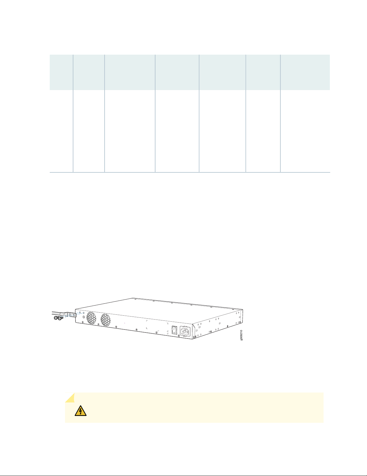
Table 24: Parts and Tools Required for Connecting an MX150 to Earth Ground
g009210
63
Grounding
Lug
Specifications
Panduit
LCC10-14BWL
or equivalent—
not provided
Screws and
Washers
Two 10-32
•
x .25 in.
screws with
#10 split-lock
washer—
not provided
Two #10 flat
•
washers—not
provided
Additional
InformationScrewdriver
Phillips (+)
number 2
MX150
Earthing
Terminal
LocationDevice
Rear panel
of chassis
Grounding Cable
Requirements
14 AWG (2 mm²),
minimum 90°C
wire, or as
permitted by the
local code
Connecting Earth Ground to an MX150
To connect earth ground to the MX150:
1. Connect one end of the grounding cable to a proper earth ground, such as the rack in which the router
is mounted.
2. Place the grounding lug attached to the grounding cable over the protective earthing terminal. See
Figure 16 on page 63.
Figure 16: Connecting a Grounding Cable to an MX150
3. Secure the grounding lug to the protective earthing terminal with the washers and screws.
4. Dress the grounding cable and ensure that it does not touch or block access to other device components.
WARNING: Ensure that the cable does not drape where people could trip over it.
Page 64

Connecting AC Power to an MX150
The power supply in an MX150 is located on the rear panel.
Ensure that you have the following parts and tools available:
A power cord appropriate for your geographical location
•
A power cord retainer clip
•
CAUTION: An MX150 gets additional grounding when you plug the power supply in
the device into a grounded AC power outlet by using the AC power cord appropriate
for your geographical location (see “AC Power Cord Specifications for an MX150” on
page 27).
To connect AC power to the device:
64
1. Squeeze the two sides of the power cord retainer clip and insert the L-shaped ends of the wire clip
into the holes in the bracket on each side of the AC power cord inlet on the rear panel.
The power cord retainer clip extends out of the chassis by 3 in. (7.62 cms).
2. Locate the power cord or cords shipped with the device; the cords have plugs appropriate for your
geographical location. See “AC Power Cord Specifications for an MX150” on page 27.
WARNING: Ensure that the power cord does not drape where people can trip on
it or block access to switch components.
3. Insert the coupler end of the power cord into the AC power cord inlet on the rear panel.
4. Push the power cord into the slot in the adjustment nut of the power cord retainer clip. Turn the nut
until it is tight against the base of the coupler and the slot in the nut is turned 90° from the top of the
device.
5. If the AC power source outlet has a power switch, set it to the off (0) position.
6. Insert the power cord plug into an AC power source outlet.
7. If the AC power source outlet has a power switch, set it to the on (|) position.
Page 65

NOTE: The retainer brackets on your switch might be above and below the power inlet rather
than on either side.
Figure 17: Connecting an AC Power Cord to the AC Power Cord Inlet on MX150
SEE ALSO
65
AC Power Supply Specifications for an MX150 | 26
AC Power Cord Specifications for an MX150 | 27
Connecting the MX150 to the Network
IN THIS SECTION
Connecting an MX150 to a Management Console | 65
Connecting an MX150 to a Management Console Using Mini-USB Type-B Console Port | 67
Connecting an MX150 to a Management Console
MX150 has a console port with an RJ-45 connector. Use the console port to connect the device to a
management console or to a console server.
Ensure that you have an RJ-45 to DB-9 rollover cable available. An RJ-45 cable with an RJ-45 to DB-9
adapter is provided with the device.
Page 66

NOTE: If your laptop or PC does not have a DB-9 plug connector pin and you want to connect
your laptop or PC directly to the MX150, use a combination of the RJ-45 cable and RJ-45 to
DB-9 adapter supplied with the device and a USB to DB-9 plug adapter. You must provide the
USB to DB-9 plug adapter.
To connect the MX150 to a management console (see Figure 18 on page 66 and Figure 19 on page 66):
1. Connect one end of the Ethernet cable to the console port (labeled CON).
2. Connect the other end of the Ethernet cable into the console server (see Figure 18 on page 66) or
management console (see Figure 19 on page 66).
Figure 18: Connecting the MX150 to a Management Console Through a Console Server
66
Figure 19: Connecting the MX150 Directly to a Management Console
SEE ALSO
Console Port Connector Pinouts for MX150 | 39
Page 67

Connecting an MX150 to a Management Console Using Mini-USB Type-B Console Port
You can configure and manage the MX150 by using the RJ-45 console port or the Mini-USB Type-B
console port. However, the console input will be active only on one port at a time—only one port will be
set active at a time.
By default, the RJ-45 port is set as an active console port and the Mini-USB Type-B port is the passive
console port. For information about configuring the console port type, see Configuring the Console Port
Type (CLI Procedure).
If your laptop or PC does not have a DB-9 plug connector pin or RJ-45 connector pin, you can connect
your laptop or PC directly to an MX150 device by using a mini-USB cable that has a Standard-A USB
connector on one end and a Mini-USB Type-B (5 pin) connector on the other end.
This section describes the process of connecting an MX150 to the management console by using the
Mini-USB Type-B console port.
67
For information about configuring and managing an MX150 by using the RJ-45 console port, see “Connecting
an MX150 to a Management Console” on page 65.
Before you begin connecting an MX150 by using the Mini-USB Type-B console port:
Ensure that the USB to Serial driver is installed on the host machine. You can download the driver from
•
https://webdownload.juniper.net/swdl/dl/secure/site/1/record/5029.html
Ensure that the hyper terminal properties of the console server or laptop are set as follows:
•
Baud rate—9600
•
Flow control—None
•
Data—8
•
Parity—None
•
Stop bits—1
•
DCD state—Disregard
•
Ensure that you have the following parts and tools available:
1 mini-USB cable with Standard-A and Mini-USB Type- B (5-pin) connectors (not provided).
•
To connect the MX150 to the console by using Mini-USB Type-B console port:
1. Connect the Standard-A connector of the mini-USB cable to the host machine (PC or Laptop).
2. Connect the Mini-USB Type-B (5-pin) connector of the mini-USB cable to the Mini-USB Type-B console
port (labeled CON) on the MX150.
Page 68

3. Set the Mini-USB Type-B console port as the active console port by using the command port-type.
For information about configuring the console port type, see Configuring the Console Port Type (CLI
Procedure).
4. Reboot the MX150.
After the connection is established, the Mini-USB Type-B becomes the active console port. The host
machine connected to the Mini-USB Type-B console port displays log messages and lets you control
MX150 functionality through it.
SEE ALSO
Console Port Connector Pinouts for MX150 | 39
68
Performing the Initial Software Configuration for the MX150
You must perform the initial configuration of the MX150 through the console port using the command-line
interface (CLI).
Before you begin connecting and configuring an MX150, set the following parameter values on the console
server or PC:
Baud Rate—9600
•
Flow Control—None
•
Data—8
•
Parity—None
•
Stop Bits—1
•
DCD State—Disregard
•
To connect and configure the device from the console:
1. Connect the console port to a laptop or PC by using the supplied RJ-45 cable and RJ-45 to DB-9
adapter. The console (CON) port is located on the management panel of the device.
2. Start the CLI.
Page 69

root@host% cli
3. Enter configuration mode.
root@host> configure
4. Add a password to the root administration user account.
[edit]
root@host# set system root-authentication plain-text-password
New password: password
Retype new password: password
5. (Optional) Configure the name of the device. If the name includes spaces, enclose the name in quotation
marks (“ ”).
[edit]
root@host# set system host-name host-name
69
6. Configure the IP address and prefix length for the device management interface.
[edit]
root@host# set interfaces fxp0 unit 0 family inet address address/prefix-length
fxp0 is the management interface.
To configure an IPV6 address, run the root@host# set interface fxp0 family inet6 address address
v6_address.
NOTE: fxp0 is found on the front panel of the MX150 device.
7. Configure the default gateway.
[edit]
root@host# set routing-options static route default next-hop address
8. Enable the SSH service.
[edit]
root@host# set system services ssh
9. Enable the Telnet service.
[edit]
Page 70

root@host# set system services telnet
10. Commit the configuration to activate it on the device.
[edit]
root@host# commit
RELATED DOCUMENTATION
MX150 Installation Overview | 52
70
Page 71

4
CHAPTER
Maintaining Components
Maintaining MX150 Transceivers and Fiber-Optic Cables | 72
Removing the MX150 | 79
Page 72

Maintaining MX150 Transceivers and Fiber-Optic Cables
IN THIS SECTION
Removing a Transceiver from an MX150 | 72
Installing a Transceiver in an MX150 | 74
Maintaining Fiber-Optic Cables in an MX150 | 76
Connecting a Fiber-Optic Cable to an MX150 | 76
Disconnecting a Fiber-Optic Cable from an MX150 | 78
72
Removing a Transceiver from an MX150
The transceivers for the MX150 are hot-removable and hot-insertable field-replaceable units (FRUs). You
can remove and replace them without powering off the device or disrupting device functions.
Before you begin removing a transceiver from the MX150, ensure that you have taken the necessary
precautions for safe handling of lasers (see “Laser and LED Safety Guidelines and Warnings for the MX150”
on page 111).
Ensure that you have the following parts and tools available:
Electrostatic bag or an antistatic mat
•
Rubber safety caps to cover the transceiver and fiber-optic cable connector
•
Dust cover to cover the port
•
To remove a transceiver from the MX150:
1. Place the antistatic bag or antistatic mat on a flat, stable surface.
2. Label the cable connected to the transceiver so that you can reconnect it correctly.
WARNING: Do not look directly into a fiber-optic transceiver or into the ends of
fiber-optic cables. Fiber-optic transceivers and fiber-optic cables connected to
transceivers emit laser light that can damage your eyes.
Page 73

WARNING: Do not leave a fiber-optic transceiver uncovered except when inserting
or removing a cable. The rubber safety cap keeps the port clean and prevents
accidental exposure to laser light.
CAUTION: Do not bend fiber-optic cables beyond their minimum bend radius.
Bending the cables beyond their minimum bend radius can damage the cables and
cause problems that are difficult to diagnose.
3. Remove the cable connected to the transceiver (see “Disconnecting a Fiber-Optic Cable from an MX150”
on page 78). Cover the transceiver and the end of each fiber-optic cable connector with a rubber safety
cap immediately after disconnecting the fiber-optic cables.
4. Using your fingers, pull the ejector lever away from the transceiver to unlock the transceiver.
73
CAUTION: Before removing the transceiver, make sure you open the ejector lever
completely until you hear it click. Doing this prevents damage to the transceiver.
5. Grasp the transceiver ejector lever and gently slide the transceiver approximately 0.5 in. (1.3 cm) straight
out of the port (see Figure 20 on page 74).
CAUTION: To avoid electrostatic discharge (ESD) damage to the transceiver, do
not touch the connector pins at the end of the transceiver.
6. Using your fingers, grasp the body of the transceiver and pull it straight out of the port.
7. Place the transceiver in the electrostatic bag or on the antistatic mat placed on a flat, stable surface.
8. Place the dust cover over the empty port.
Page 74

Figure 20: Removing a Transceiver from an MX150
Installing a Transceiver in an MX150
74
The transceivers for the MX150 are hot-removable and hot-insertable field-replaceable units (FRUs). You
can remove and replace them without powering off the device or disrupting device functions.
Before you begin installing a transceiver in an MX150, ensure that you have taken the necessary precautions
for safe handling of lasers (see “Laser and LED Safety Guidelines and Warnings for the MX150” on page 111).
Ensure that you have a rubber safety cap available to cover the transceiver.
To install a transceiver in an MX150 :
CAUTION: To avoid electrostatic discharge (ESD) damage to the transceiver, do not
touch the connector pins at the end of the transceiver.
1. Remove the transceiver from its bag.
2. Check to see whether the transceiver is covered by a rubber safety cap. If it is not, cover the transceiver
with a rubber safety cap.
WARNING: Do not leave a fiber-optic transceiver uncovered except when inserting
or removing a cable. The rubber safety cap keeps the port clean and prevents
accidental exposure to laser light.
Page 75

3. If the port in which you want to install the transceiver is covered with a dust cover, remove the dust
cover and save it in case you need to cover the port later.
4. Using both hands, carefully place the transceiver in the empty port. The connectors must face the
device chassis.
CAUTION: Before you slide the transceiver into the port, ensure that the transceiver
is aligned correctly. Misalignment might cause the pins to bend, making the
transceiver unusable. See Figure 21 on page 75 for the correct orientation for your
device.
5. Slide the transceiver in gently until it is fully seated. See Figure 21 on page 75 for an example of inserting
an SFP or SFP+ transceiver.
6. Remove the rubber safety cap when you are ready to connect the cable to the transceiver.
75
WARNING: Do not look directly into a fiber-optic transceiver or into the ends of
fiber-optic cables. Fiber-optic transceivers and fiber-optic cables connected to
transceivers emit laser light that can damage your eyes.
Figure 21: Installing a Transceiver in an MX150
Page 76

Maintaining Fiber-Optic Cables in an MX150
To maintain fiber-optic cables in MX150:
When you unplug a fiber-optic cable from a transceiver, place rubber safety caps over the transceiver
•
and on the end of the cable.
Anchor fiber-optic cable to avoid stress on the connectors. When attaching a fiber-optic cable to a
•
transceiver, be sure to secure the fiber-optic cable so that it is not supporting its own weight as it hangs
to the floor. Never let a fiber-optic cable hang free from the connector.
Do not bend fiber-optic cables beyond their minimum bend radius. Bending the cables beyond their
•
minimum bend radius can damage the cables and cause problems that are difficult to diagnose.
Frequent plugging and unplugging of fiber-optic cables in and out of optical instruments can damage
•
the instruments, which are expensive to repair. Attach a short fiber extension to the optical equipment.
Any wear and tear due to frequent plugging and unplugging is then absorbed by the short fiber extension,
which is easier and less expensive to replace than the instruments.
76
Keep fiber-optic cable connections clean. Microdeposits of oil and dust in the canal of the transceiver
•
or cable connector can cause loss of light, reduction in signal power, and possibly intermittent problems
with the optical connection.
To clean the transceiver canal, use an appropriate fiber-cleaning device such as RIFOCS Fiber Optic
Adaptor Cleaning Wands (part number 946). Follow the directions in the cleaning kit you use.
After cleaning the transceiver, make sure that the connector tip of the fiber-optic cable is clean. Use
only an approved alcohol-free fiber-optic cable cleaning kit such as the Cletop-S®Fiber Cleaner. Follow
the directions in the cleaning kit you use.
Connecting a Fiber-Optic Cable to an MX150
You can connect fiber-optic cables to the field-replaceable unit (FRU) optical transceivers installed in
MX150 routers.
Before you connect a fiber-optic cable to an optical transceiver installed in an MX150, ensure that you
have taken the necessary precautions for safe handling of lasers (see “Laser and LED Safety Guidelines
and Warnings for the MX150” on page 111).
Page 77

To connect a fiber-optic cable to an optical transceiver installed in an MX150:
WARNING: Do not look directly into a fiber-optic transceiver or into the ends of
fiber-optic cables. Fiber-optic transceivers and fiber-optic cables connected to
transceivers emit laser light that can damage your eyes.
WARNING: Do not stare into the laser beam or view it directly with optical instruments
even if the interface has been disabled.
1. If the fiber-optic cable connector is covered by a rubber safety cap, remove the cap. Save the cap.
2. If the optical transceiver is covered by a rubber safety cap, remove the cap. Save the cap.
77
3. Insert the cable connector into the optical transceiver (see Figure 22 on page 78).
4. Secure the cables so that they are not supporting their own weight. Place excess cable out of the way
in a neatly coiled loop. Placing fasteners on a loop helps cables maintain their shape.
CAUTION: Do not bend fiber-optic cables beyond their minimum bend radius.
Bending the cables beyond their minimum bend radius can damage the cables and
cause problems that are difficult to diagnose.
CAUTION: Do not let fiber-optic cables hang free from the connector. Do not
allow fastened loops of cables to dangle, which stresses the cables at the fastening
point.
Page 78

Figure 22: Inserting a Fiber-Optic Cable into a Transceiver
Disconnecting a Fiber-Optic Cable from an MX150
78
Before you disconnect a fiber-optic cable from an optical transceiver installed in an MX150, ensure that
you have taken the necessary precautions for safe handling of lasers (see “Laser and LED Safety Guidelines
and Warnings for the MX150” on page 111).
Ensure that you have the following parts and tools available:
Rubber safety cap to cover the transceiver
•
Rubber safety cap to cover the fiber-optic cable connector
•
To disconnect a fiber-optic cable from an optical transceiver installed in the MX150:
1. (Recommended) Disable the port in which the transceiver is installed by including the disable statement
at the [edit interfaces] hierarchy level for the specific interface.
WARNING: Do not look directly into a fiber-optic transceiver or into the ends of
fiber-optic cables. Fiber-optic transceivers and fiber-optic cables connected to
transceivers emit laser light that can damage your eyes.
WARNING: Do not stare into the laser beam or view it directly with optical
instruments even if the interface has been disabled.
2. Carefully unplug the fiber-optic cable connector from the transceiver.
Page 79

3. Cover the transceiver with a rubber safety cap.
WARNING: Do not leave a fiber-optic transceiver uncovered except when inserting
or removing a cable. The rubber safety cap keeps the port clean and prevents
accidental exposure to laser light.
4. Cover the fiber-optic cable connector with the rubber safety cap.
Removing the MX150
IN THIS SECTION
79
Powering Off an MX150 | 79
Removing an MX150 from a Rack or Cabinet | 81
Powering Off an MX150
If you need to power off the MX150, follow the procedure in this topic.
Before you power off the device:
Ensure that you understand how to prevent electrostatic discharge damage. See “Prevention of
•
Electrostatic Discharge Damage” on page 130.
Ensure that you do not need to forward traffic through the device.
•
Ensure that you have the following parts and tools available to power off the device:
An ESD grounding strap
•
An external management device such as a PC
•
A cable to connect the external management device to the console port (CON) or management port
•
(MGMT) on the device
To power off the device:
Page 80

1. Connect the management device (such as a PC) to the console (CON) port or the management (MGMT)
port on the device:
For connecting a management device to the console port, see “Connecting an MX150 to a Management
•
Console” on page 65.
2. From the PC connected to the device, issue the following operational mode CLI command:
user@host> request system halt
This command shuts down the device gracefully and preserves system state information. A message
displays on the console confirming that the operating system has halted.
You will see the following output (or something similar, depending on the hardware being shut down):
user@host> request system halt
warning: This command will halt all the members.
If planning to halt only one member use the member option
Halt the system ? [yes,no] (no) yes
80
*** FINAL System shutdown message from user@host ***
System going down IMMEDIATELY
Shutdown NOW!
[pid 14102]
message sent
{master:0}
user@host> Waiting (max 300 seconds) for system process `vnlru' to stop...done
Waiting (max 300 seconds) for system process `vnlru_mem' to stop...done
Waiting (max 300 seconds) for system process `bufdaemon' to stop...done
Waiting (max 300 seconds) for system process `syncer' to stop...
Syncing disks, vnodes remaining...3 3 1 2 2 0 0 0 0 done
syncing disks... All buffers synced.
Uptime: 38d18h0m6s
recorded reboot as normal shutdown
The operating system has halted.
Please press any key to reboot
Page 81

CAUTION: The final output of any version of this command is the “The operating
system has halted. Please press any key to reboot” message. Wait at least 60 seconds
after first seeing this message before following the instructions in Step 3 and Step
4 to power off the device.
CAUTION: Ensure that you have halted your system safely before turning off the
power supply.
3. Attach the ESD grounding strap to your bare wrist and connect the strap to the ESD point on the
chassis.
4. Set the power switch to off (0) position.
81
SEE ALSO
Connecting AC Power to an MX150 | 64
Removing an MX150 from a Rack or Cabinet
If you need to relocate an installed MX150, use the procedure described in this topic. (The remainder of
this topic uses rack to mean rack or cabinet.)
NOTE: When you remove multiple devices from a rack, remove the device at the top of the rack
first and proceed to remove the rest of the devices from top to bottom.
CAUTION: At least two people must be available to lift a device chassis out of a
rack—one person to unscrew the mounting screws from the brackets and the second
person to hold the chassis.
Before removing the MX150 from a rack:
Page 82

Ensure that the rack or cabinet is stable and secured to the building.
•
Ensure that there is enough space to place the removed device in its new location and along the path
•
to the new location.
Read “General Safety Guidelines and Warnings” on page 94, with particular attention to “Chassis Lifting
•
Guidelines for MX150” on page 101.
Ensure that the device has been safely powered off and that you have unplugged (disconnected) the
•
power cords.
Ensure that you have disconnected any cables or wires attached to the device.
•
Ensure that you have the following parts and tools available to remove the device:
A Phillips (+) screwdriver, number 2 or number 3, depending on the size of your rack mounting screws.
•
A labeled bag to hold the removed screws.
•
To remove an MX150 from a rack:
1. Use the appropriate Phillips (+) screwdriver to remove the mounting screws that attach the chassis
front-mounting brackets to the rack.
82
2. Place the removed screws in a labeled bag. You will need them when you reinstall the chassis.
3. Lift the chassis from the rack and carefully move the chassis to its new location.
SEE ALSO
General Safety Guidelines and Warnings | 94
Chassis Lifting Guidelines for MX150 | 101
Page 83

5
CHAPTER
Troubleshooting Hardware
Understanding Alarm Types and Severity Levels on MX150 | 84
Page 84

Understanding Alarm Types and Severity Levels on MX150
Alarms alert you to conditions that might prevent normal operation of the MX150. Table 25 on page 84
provides a list of alarm terms and definitions that might help you in monitoring the device.
Table 25: Alarm Terms and Definitions
DefinitionTerm
84
Alarm
Alarm severity
levels
Alarm types
Signal alerting you to conditions that might prevent normal operation. LEDs are the alarm indicators
on the device. Blinking amber LEDs indicate yellow alarm conditions for chassis components.
Failure event that triggers an alarm.Alarm condition
Seriousness of the alarm. The level of severity can be either major (red) or minor (yellow).
Major (red)—Indicates a critical situation on the device that has resulted from one of the following
•
conditions. A red alarm condition requires immediate action.
One or more hardware components have failed.
•
One or more hardware components have exceeded temperature thresholds.
•
An alarm condition configured on an interface has triggered a critical warning.
•
Minor (yellow or amber)—Indicates a noncritical condition on the device that, if left unchecked,
•
might cause an interruption in service or degradation in performance. A yellow alarm condition
requires monitoring or maintenance. For example, a missing rescue configuration generates a
yellow system alarm.
Alarms include the following types:
Chassis alarm—Predefined alarm triggered by a physical condition on the device such as a power
•
supply failure or excessive component temperature.
Interface alarm—Alarm you configure to alert you when an interface link is down. Applies to
•
ethernet, fibre-channel, and management-ethernet interfaces. You can configure a red (major)
or yellow (minor) alarm for the link-down condition, or have the condition ignored.
System alarm—Predefined alarm that might be triggered by a missing rescue configuration, failure
•
to install a license for a licensed software feature, or high disk usage.
RELATED DOCUMENTATION
MX150 Router Overview | 16
Page 85

6
CHAPTER
Contacting Customer Support and
Returning the Chassis or Components
Contacting Customer Support and Returning the Chassis or Components | 86
Page 86

Contacting Customer Support and Returning the Chassis or Components
IN THIS SECTION
Contacting Customer Support to Obtain a Return Materials Authorization for an MX150 | 86
Locating the Serial Number on an MX150 | 87
Packing a MX150 Router or Component for Shipping | 89
Returning a MX150 Router or Component for Repair or Replacement | 90
86
Contacting Customer Support to Obtain a Return Materials Authorization for an MX150
If you are returning an MX150 router or component to Juniper Networks for repair or replacement, obtain
a Return Materials Authorization (RMA) from the Juniper Networks Technical Assistance Center (JTAC).
After locating the serial number of the device or component you want to return, open a service request
with Juniper Networks Technical Assistance Center (JTAC) on the Web or by telephone.
For instructions on locating the serial number of the device or component you want to return, see “Locating
the Serial Number on an MX150” on page 87.
Before you request an RMA from JTAC, be prepared to provide the following information:
Your existing service request number, if you have one
•
Serial number of the component
•
Your name, organization name, telephone number, fax number, and shipping address
•
Details of the failure or problem
•
Type of activity being performed on the device when the problem occurred
•
Configuration data displayed by one or more show commands
•
You can contact JTAC 24 hours a day, seven days a week on the Web or by telephone:
Service Request Manager: https://support.juniper.net/support
•
Telephone: +1-888-314-JTAC (+1-888-314-5822), toll-free in the USA, Canada, and Mexico
•
Page 87

NOTE: For international or direct-dial options in countries without toll-free numbers, see
https://support.juniper.net/support/ .
If you are contacting JTAC by telephone, enter your 12-digit service request number followed by the
pound (#) key for an existing case, or press the star (*) key to be routed to the next available support
engineer.
The support representative validates your request and issues an RMA number for return of the component.
Locating the Serial Number on an MX150
IN THIS SECTION
87
Listing the Device and Components Details with the CLI | 87
Locating the Chassis Serial Number ID Label on an MX150 | 88
If you are returning a device to Juniper Networks for repair or replacement, you must locate the serial
number of the device. You must provide the serial number to the Juniper Networks Technical Assistance
Center (JTAC) when you contact them to obtain Return Materials Authorization (RMA).
If the device is operational and you can access the CLI, you can list serial numbers for the device with a
CLI command.
NOTE: The MX150 does not have any field-replaceable unit. The power supply and fans are
fixed.
Listing the Device and Components Details with the CLI
To list the device and device components and their serial numbers, enter the following CLI command:
The following output lists the device components and serial numbers for an MX150:
Page 88

NOTE: Log in to the Junos command-line interface (Junos CLI).
user@host> show chassis hardware
Hardware inventory:
Item Version Part number Serial number Description
Chassis DD2316AF0078 MX150
Midplane REV 04 650-066113 DD2316AF0078 MX150
Power Supply 0
Routing Engine 0 RE-MX
CB 0 MX SCB
CB 1 MX SCB
FPC 0 Virtual FPC
CPU Rev. 1.0 RIOT BUILTIN
MIC 0 Virtual
PIC 0 BUILTIN BUILTIN Virtual
Xcvr 10 REV 02 740-013111 A331846 SFP-T
Xcvr 11 REV 02 740-013111 C248517 SFP-T
Fan Tray 0 fan-ctrl-0 0, Front to
Back Airflow - AFO
Fan Tray 1 fan-ctrl-0 1, Front to
Back Airflow - AFO
88
For information about the show chassis hardware command, see the Junos OS System Basics and Services
Command Reference at https://www.juniper.net/documentation/software/junos/index.html .
Locating the Chassis Serial Number ID Label on an MX150
The serial number ID label is located on the back of the chassis on an MX150. See Figure 23 on page 88.
Figure 23: Location of the Serial Number ID Label on an MX150
Page 89

Packing a MX150 Router or Component for Shipping
IN THIS SECTION
Packing an MX150 for Shipping | 89
Packing MX150 Components for Shipping | 90
If you are returning a MX150 router or component to Juniper Networks for repair or replacement, pack
the item as described in this topic.
Before you pack a MX150 router or component:
Ensure that you have taken the necessary precautions to prevent electrostatic discharge (ESD) damage.
•
See “Prevention of Electrostatic Discharge Damage” on page 130.
89
Retrieve the original shipping carton and packing materials. Contact your JTAC representative if you do
•
not have these materials, to learn about approved packing materials. See “Contacting Customer Support
to Obtain a Return Materials Authorization for an MX150” on page 86.
Ensure that you have the following parts and tools available:
ESD grounding strap.
•
Antistatic bag, one for each component.
•
If you are returning the chassis, an appropriate screwdriver for the mounting screws used on your rack
•
or cabinet.
This topic describes:
Packing an MX150 for Shipping
To pack an MX150 for shipping:
1. Power off the MX150 and remove the power cables. See “Powering Off an MX150” on page 79.
2. Remove the cables that connect the device to all external devices.
3. Remove all field-replaceable units (FRUs) from the MX150.
4. Have one person support the weight of the device while another person unscrews and removes the
mounting screws.
Page 90

5. Remove the device from the rack or cabinet (see “Chassis Lifting Guidelines for MX150” on page 101)
and place the device in an antistatic bag.
6. Place the device in the shipping carton.
7. Place the packing foam on top and around the device.
8. If you are returning accessories or FRUs with the device, pack them as instructed in “Packing a MX150
Router or Component for Shipping” on page 89.
9. Replace the accessory box on top of the packing foam.
10. Close the top of the cardboard shipping box and seal it with packing tape.
11. Write the RMA number on the exterior of the box to ensure proper tracking.
90
Packing MX150 Components for Shipping
CAUTION: Do not stack the MX150 components. Return individual components in
separate boxes if they do not fit together on one level in the shipping box.
To pack and ship MX150 components:
Place individual FRUs in antistatic bags.
•
Ensure that the components are adequately protected with packing materials and packed so that the
•
pieces are prevented from moving around inside the carton.
Close the top of the cardboard shipping box and seal it with packing tape.
•
Write the RMA number on the exterior of the box to ensure proper tracking.
•
Returning a MX150 Router or Component for Repair or Replacement
If you need to return a MX150 router or component to Juniper Networks for repair or replacement, follow
this procedure:
1. Determine the serial number of the device or component. For instructions, see “Locating the Serial
Number on an MX150” on page 87.
Page 91

2. Obtain a Return Materials Authorization (RMA) number from the Juniper Technical Assistance Center
(JTAC) as described in “Contacting Customer Support to Obtain a Return Materials Authorization for
an MX150” on page 86.
NOTE: Do not return any device or component to Juniper Networks unless you have first
obtained an RMA number. Juniper Networks reserves the right to refuse shipments that do
not have an RMA. Refused shipments are returned to the customer through collect freight.
3. Pack the MX150 router or component for shipping as described in “Packing a MX150 Router or
Component for Shipping” on page 89.
For more information about return and repair policies, see the customer support page at
https://www.juniper.net/support/guidelines.html .
91
SEE ALSO
MX150 Router Overview | 16
Page 92

7
CHAPTER
Safety and Compliance Information
General Safety Guidelines and Warnings | 94
Definitions of Safety Warning Levels | 95
Qualified Personnel Warning | 98
Warning Statement for Norway and Sweden | 99
Fire Safety Requirements | 99
Installation Instructions Warning | 101
Chassis Lifting Guidelines for MX150 | 101
Restricted Access Warning | 103
Ramp Warning | 105
Rack-Mounting and Cabinet-Mounting Warnings | 106
Laser and LED Safety Guidelines and Warnings for the MX150 | 111
Radiation from Open Port Apertures Warning | 120
Maintenance and Operational Safety Guidelines and Warnings | 121
General Electrical Safety Guidelines and Warnings | 129
Action to Take After an Electrical Accident | 130
Page 93

Prevention of Electrostatic Discharge Damage | 130
AC Power Electrical Safety Guidelines | 132
AC Power Disconnection Warning | 133
TN Power Warning | 134
Agency Approvals for MX150 | 134
Compliance Statements for EMC Requirements for MX150 | 136
Page 94

General Safety Guidelines and Warnings
The following guidelines help ensure your safety and protect the device from damage. The list of guidelines
might not address all potentially hazardous situations in your working environment, so be alert and exercise
good judgment at all times.
Perform only the procedures explicitly described in the hardware documentation for this device. Make
•
sure that only authorized service personnel perform other system services.
Keep the area around the device clear and free from dust before, during, and after installation.
•
Keep tools away from areas where people could trip over them while walking.
•
Do not wear loose clothing or jewelry, such as rings, bracelets, or chains, which could become caught
•
in the device.
Wear safety glasses if you are working under any conditions that could be hazardous to your eyes.
•
Do not perform any actions that create a potential hazard to people or make the equipment unsafe.
•
94
Never attempt to lift an object that is too heavy for one person to handle.
•
Never install or manipulate wiring during electrical storms.
•
Never install electrical jacks in wet locations unless the jacks are specifically designed for wet
•
environments.
Operate the device only when it is properly grounded.
•
Follow the instructions in this guide to properly ground the device to earth.
•
Replace fuses only with fuses of the same type and rating.
•
Do not open or remove chassis covers or sheet-metal parts unless instructions are provided in the
•
hardware documentation for this device. Such an action could cause severe electrical shock.
Do not push or force any objects through any opening in the chassis frame. Such an action could result
•
in electrical shock or fire.
Avoid spilling liquid onto the chassis or onto any device component. Such an action could cause electrical
•
shock or damage the device.
Avoid touching uninsulated electrical wires or terminals that have not been disconnected from their
•
power source. Such an action could cause electrical shock.
Some parts of the chassis, including AC and DC power supply surfaces, power supply unit handles, SFB
•
card handles, and fan tray handles might become hot. The following label provides the warning of the
hot surfaces on the chassis:
Page 95

Always ensure that all modules, power supplies, and cover panels are fully inserted and that the installation
•
screws are fully tightened.
Definitions of Safety Warning Levels
The documentation uses the following levels of safety warnings (there are two Warning formats):
NOTE: You might find this information helpful in a particular situation, or you might overlook
this important information if it was not highlighted in a Note.
95
CAUTION: You need to observe the specified guidelines to prevent minor injury or
discomfort to you or severe damage to the device.
WARNING: This symbol alerts you to the risk of personal injury from a laser.
Page 96

96
Page 97

WARNING: This symbol means danger. You are in a situation that could cause bodily
injury. Before you work on any equipment, be aware of the hazards involved with
electrical circuitry and be familiar with standard practices for preventing accidents.
Waarschuwing Dit waarschuwingssymbool betekent gevaar. U verkeert in een situatie
die lichamelijk letsel kan veroorzaken. Voordat u aan enige apparatuur gaat werken,
dient u zich bewust te zijn van de bij elektrische schakelingen betrokken risico's en
dient u op de hoogte te zijn van standaard maatregelen om ongelukken te voorkomen.
Varoitus Tämä varoitusmerkki merkitsee vaaraa. Olet tilanteessa, joka voi johtaa
ruumiinvammaan. Ennen kuin työskentelet minkään laitteiston parissa, ota selvää
sähkökytkentöihin liittyvistä vaaroista ja tavanomaisista onnettomuuksien
ehkäisykeinoista.
Attention Ce symbole d'avertissement indique un danger. Vous vous trouvez dans une
situation pouvant causer des blessures ou des dommages corporels. Avant de travailler
sur un équipement, soyez conscient des dangers posés par les circuits électriques et
familiarisez-vous avec les procédures couramment utilisées pour éviter les accidents.
97
Warnung Dieses Warnsymbol bedeutet Gefahr. Sie befinden sich in einer Situation,
die zu einer Körperverletzung führen könnte. Bevor Sie mit der Arbeit an irgendeinem
Gerät beginnen, seien Sie sich der mit elektrischen Stromkreisen verbundenen Gefahren
und der Standardpraktiken zur Vermeidung von Unfällen bewußt.
Avvertenza Questo simbolo di avvertenza indica un pericolo. La situazione potrebbe
causare infortuni alle persone. Prima di lavorare su qualsiasi apparecchiatura, occorre
conoscere i pericoli relativi ai circuiti elettrici ed essere al corrente delle pratiche
standard per la prevenzione di incidenti.
Advarsel Dette varselsymbolet betyr fare. Du befinner deg i en situasjon som kan føre
til personskade. Før du utfører arbeid på utstyr, må du vare oppmerksom på de
faremomentene som elektriske kretser innebærer, samt gjøre deg kjent med vanlig
praksis når det gjelder å unngå ulykker.
Aviso Este símbolo de aviso indica perigo. Encontra-se numa situação que lhe poderá
causar danos físicos. Antes de começar a trabalhar com qualquer equipamento,
familiarize-se com os perigos relacionados com circuitos eléctricos, e com quaisquer
práticas comuns que possam prevenir possíveis acidentes.
¡Atención! Este símbolo de aviso significa peligro. Existe riesgo para su integridad física.
Antes de manipular cualquier equipo, considerar los riesgos que entraña la corriente
eléctrica y familiarizarse con los procedimientos estándar de prevención de accidentes.
Page 98

Varning! Denna varningssymbol signalerar fara. Du befinner dig i en situation som kan
leda till personskada. Innan du utför arbete på någon utrustning måste du vara medveten
om farorna med elkretsar och känna till vanligt förfarande för att förebygga skador.
Qualified Personnel Warning
WARNING: Only trained and qualified personnel should install or replace the device.
Waarschuwing Installatie en reparaties mogen uitsluitend door getraind en bevoegd
personeel uitgevoerd worden.
Varoitus Ainoastaan koulutettu ja pätevä henkilökunta saa asentaa tai vaihtaa tämän
laitteen.
98
Attention Tout installation ou remplacement de l'appareil doit être réalisé par du
personnel qualifié et compétent.
Warnung Gerät nur von geschultem, qualifiziertem Personal installieren oder
auswechseln lassen.
Avvertenza Solo personale addestrato e qualificato deve essere autorizzato ad installare
o sostituire questo apparecchio.
Advarsel Kun kvalifisert personell med riktig opplæring bør montere eller bytte ut dette
utstyret.
Aviso Este equipamento deverá ser instalado ou substituído apenas por pessoal
devidamente treinado e qualificado.
¡Atención! Estos equipos deben ser instalados y reemplazados exclusivamente por
personal técnico adecuadamente preparado y capacitado.
Varning! Denna utrustning ska endast installeras och bytas ut av utbildad och
kvalificerad personal.
Page 99

Warning Statement for Norway and Sweden
WARNING: The equipment must be connected to an earthed mains socket-outlet.
Advarsel Apparatet skal kobles til en jordet stikkontakt.
Varning! Apparaten skall anslutas till jordat nätuttag.
Fire Safety Requirements
In the event of a fire emergency, the safety of people is the primary concern. You should establish
procedures for protecting people in the event of a fire emergency, provide safety training, and properly
provision fire-control equipment and fire extinguishers.
99
In addition, you should establish procedures to protect your equipment in the event of a fire emergency.
Juniper Networks products should be installed in an environment suitable for electronic equipment. We
recommend that fire suppression equipment be available in the event of a fire in the vicinity of the
equipment and that all local fire, safety, and electrical codes and ordinances be observed when you install
and operate your equipment.
Fire Suppression
In the event of an electrical hazard or an electrical fire, you should first turn power off to the equipment
at the source. Then use a Type C fire extinguisher, which uses noncorrosive fire retardants, to extinguish
the fire.
Fire Suppression Equipment
Type C fire extinguishers, which use noncorrosive fire retardants such as carbon dioxide and Halotron™,
are most effective for suppressing electrical fires. Type C fire extinguishers displace oxygen from the point
of combustion to eliminate the fire. For extinguishing fire on or around equipment that draws air from the
environment for cooling, you should use this type of inert oxygen displacement extinguisher instead of an
extinguisher that leaves residues on equipment.
Page 100

Do not use multipurpose Type ABC chemical fire extinguishers (dry chemical fire extinguishers). The
primary ingredient in these fire extinguishers is monoammonium phosphate, which is very sticky and
difficult to clean. In addition, in the presence of minute amounts of moisture, monoammonium phosphate
can become highly corrosive and corrodes most metals.
Any equipment in a room in which a chemical fire extinguisher has been discharged is subject to premature
failure and unreliable operation. The equipment is considered to be irreparably damaged.
NOTE: To keep warranties effective, do not use a dry chemical fire extinguisher to control a fire
at or near a Juniper Networks device. If a dry chemical fire extinguisher is used, the unit is no
longer eligible for coverage under a service agreement.
We recommend that you dispose of any irreparably damaged equipment in an environmentally responsible
manner.
100
 Loading...