


MX104 Universal Routing Platforms
Quick Start
April 2016
Part Number: 530-062013
Revision 02
This document describes how to install the Juniper Networks®MX104 Universal Routing Platform.
1
Contents
MX104 Quick Start Description | 3
Step 1: Prepare the Site for MX104 Router Installation | 5
Step 2: Install the Router | 7
Tools Required to Install the Router in a Rack | 7
Install the MX104 Router in the Rack | 7
Step 3: Ground the MX104 Router | 9
Tools Required to Ground the MX104 Router | 9
Connect the Grounding Cable | 9
Step 4: Connect External Devices and Cables | 12
Connect the Router to a Network for Out-of-Band Management | 12
Connect the Router to a Management Console Device | 12
Connect MIC Cables to the MX104 Router | 13
Step 5: Connect Power to the MX104 Router | 15
Connect AC Power to an AC-Powered MX104 Router | 15
Connect DC Power to a DC-Powered MX104 Router | 16
Step 6: Perform Initial Software Configuration | 21
Enter Configuration Mode | 21
Configure User Accounts and Passwords | 22
Configure System Attributes | 22
Commit the Configuration | 23
Safety Warnings | 25

Compliance Statements for NEBS | 26
Compliance Statements for EMC Requirements | 27
Canada | 27
European Community | 27
Israel | 27
Japan | 28
United States | 28
Junos OS Documentation and Release Notes | 29
Requesting Technical Support | 29
Self-Help Online Tools and Resources | 29
Creating a Service Request with JTAC | 30
Revision History | 30
2
MX104 Quick Start Description
This Quick Start contains information you need to install and configure the router quickly. For complete
installation instructions, see the MX104 Universal Routing Platform Hardware Guide at
https://www.juniper.net/documentation/.
WARNING: This Quick Start contains a summary of safety warnings in “Safety
Warnings” on page 25. For a complete list of warnings for this router, including
translations, see the MX104 Universal Routing Platform Hardware Guide at
https://www.juniper.net/documentation/.
The router is environmentally hardened and is 3.5 rack units (U; that is 6.125 in., or 15.55 cm) tall. Several
routers can be stacked in a single floor-to-ceiling rack, for increased port density per unit of floor space.
The chassis installs in standard 11.81 in. (30 cm)-deep (or larger) enclosed cabinets, 19-in. equipment racks,
or telco open-frame racks.
3
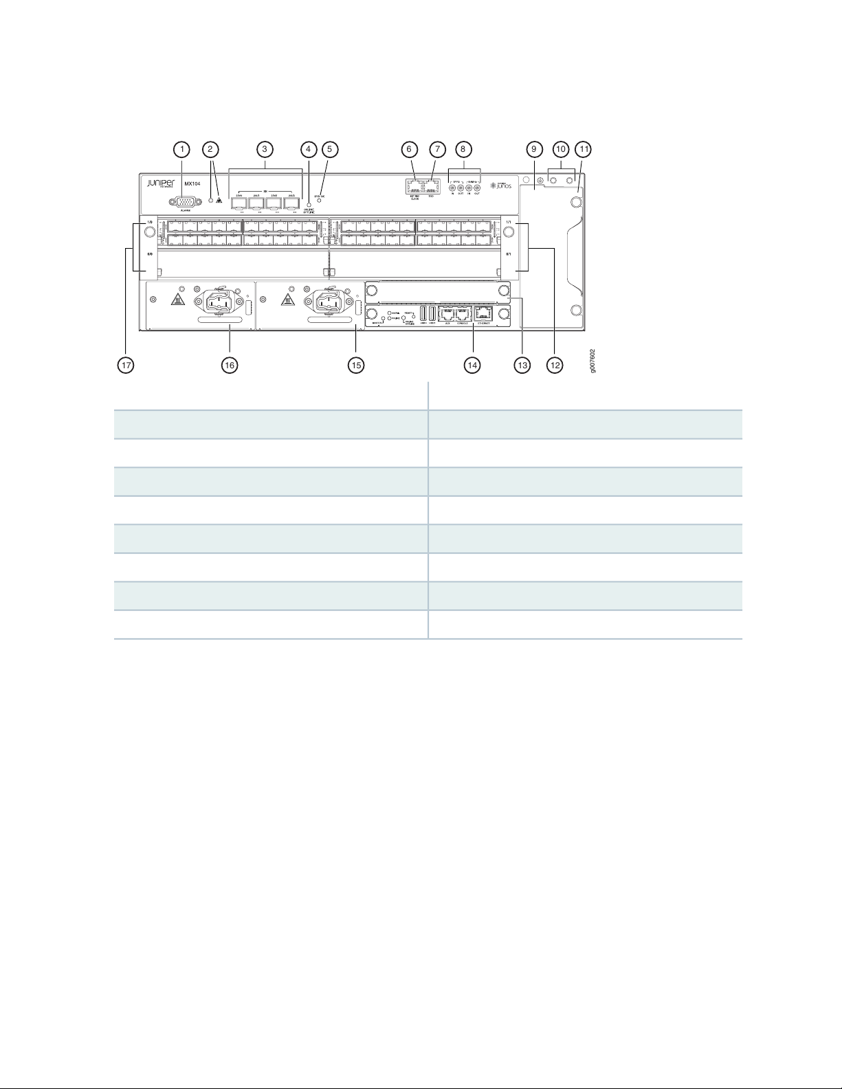
Figure 1: Front View of the MX104 Router
g007602
17 16 15 1314 12
31 54 10 1198762
4
10—1— Grounding terminalsAlarm input and output contacts
11—2— Fan trayAlarm LEDs
9—ESD point
12—3— MIC slots 0/1 and 1/110-Gigabit Ethernet SFP+ ports
13—4— Routing EngineONLINE/OFFLINE button
14—5— Routing EngineSystem status LED
15—6— Power supplies (AC or DC)External reference clocking port
16—7— Power supplies (AC or DC)Time-of-day (TOD) port
17—8— MIC slots 0/0 and 1/01-PPS and 10-MHz GPS input and output ports

Step 1: Prepare the Site for MX104 Router Installation
Prepare your site for MX104 installation by observing the following guidelines:
You can install the router in a four-post rack or cabinet or an open-frame rack.
•
The rack rails must be spaced widely enough to accommodate the chassis's external dimensions: 6.125
•
in. or (15.55 cm) high, 9.5 in. (24.13 cm) deep, and 17.5 in. (44.5 cm) wide. The outer edges of the
mounting brackets extend the width to 19.2 in. (48.7 cm).
One person must be available to lift the router while another secures the router to the rack.
•
The rack must be strong enough to support the weight of the fully configured router, up to 32 lb (14.5 kg).
•
For the cooling system to function properly, the airflow around the chassis must be unrestricted. Allow
•
at least 6 in. (15.2 cm) of clearance between side-cooled devices. Allow 2.8 in. (7 cm) between the side
of the chassis and any non-heat-producing surface such as a wall.
For service personnel to remove and install hardware components, there must be adequate space at the
•
front and back of the router. Allow at least 30 in. (76.2 cm) in front of the router and 24 in. (61 cm)
behind the router.
5
The rack or cabinet must have an adequate supply of cooling air.
•
Ensure that the cabinet allows the chassis hot exhaust air to exit from the cabinet without recirculating
•
into the router.
You must install the router into a rack that is secured to the building structure.
•
Mount the router at the bottom of the rack if it is the only unit in the rack.
•
When mounting the router in a partially filled rack, load the rack from the bottom to the top with the
•
heaviest component at the bottom of the rack.
Install the router only in restricted areas, such as dedicated equipment rooms and equipment closets, in
•
accordance with Articles 110-16, 110-17, and 110-18 of the National Electrical Code, ANSI/NFPA 70.
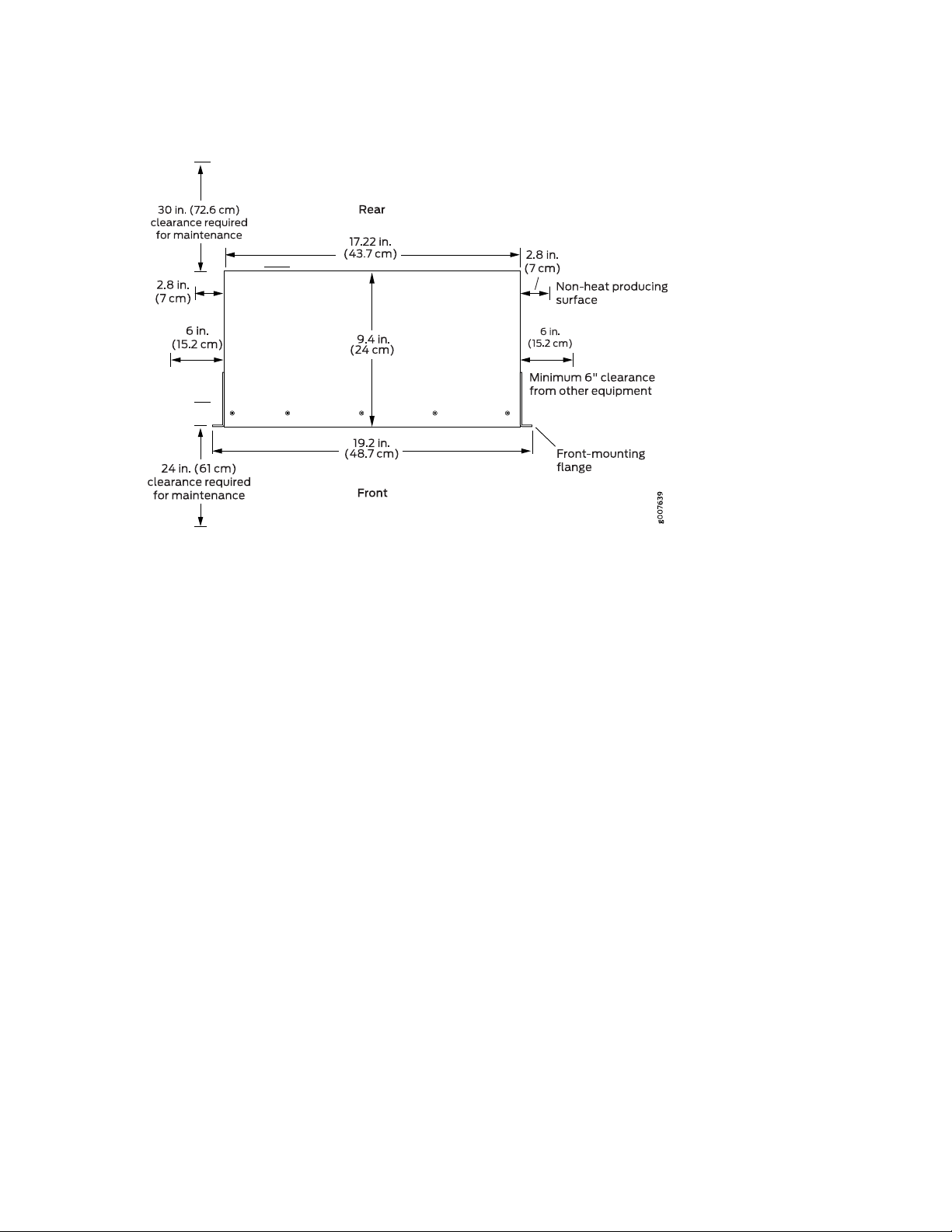
Figure 2: MX104 Rack Clearance and Chassis Dimensions
6
Step 2: Install the Router
IN THIS SECTION
Tools Required to Install the Router in a Rack | 7
Install the MX104 Router in the Rack | 7
Tools Required to Install the Router in a Rack
To install the router in a rack, you need the following tools:
Phillips (+) screwdriver, number 2
•
7
ESD grounding wrist strap
•
Install the MX104 Router in the Rack
The router can be installed horizontally in a rack or cabinet.
Two people are required to install the MX104 router. The chassis weighs approximately 32 lb (14.5 kg).
To install the chassis (see Figure 3 on page 8):
1. Ensure that the rack is in its permanent location and is secured to the building. Ensure that the installation
site allows adequate clearance for both airflow and maintenance.
2. Position the router in front of the rack or cabinet.
3. Have one person grasp both sides of the router, lift the router, and position it in the rack, aligning the
mounting bracket holes with the threaded holes in the rack rails. Make sure the chassis is level.
4. Have the second person install a mounting screw into each of the open mounting holes aligned with
the rack, starting from the bottom.
5. Visually inspect the alignment of the router. If the router is installed properly in the rack, all the mounting
screws on one side of the rack should be aligned with the mounting screws on the opposite side, and
the router should be level.
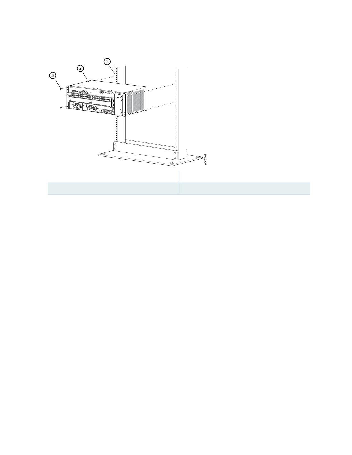
Figure 3: Installing the Front-Mounted Router in the Rack
3—1— Mounting screwsRack
2—MX104 router
8
Step 3: Ground the MX104 Router
IN THIS SECTION
Tools Required to Ground the MX104 Router | 9
Connect the Grounding Cable | 9
Tools Required to Ground the MX104 Router
To ground the router, you need the following tools:
Phillips (+) screwdriver, number 2
•
9
ESD grounding wrist strap
•
Two SAE 10-32 screws and washers
•
Grounding lug, Panduit LCD10-10-L
•
Grounding cable, use 14-AWG (2.08 mm2) 90°C wire for AC (not provided)
•
Grounding cable, use 6-AWG (13.3 mm2) 60°C wire for 24V DC (not provided)
•
Connect the Grounding Cable
You ground the router by connecting a grounding cable to earth ground and then attaching it to the chassis
grounding points on the front of the router. To ground the router:
1. Verify that a licensed electrician has attached the cable lug provided with the router to the grounding
cable.
2. Attach an ESD grounding strap to your bare wrist, and connect the other end of the strap to an approved
site ESD grounding point. See the instructions for your site.
3. Ensure that all grounding surfaces are clean and brought to a bright finish before grounding connections
are made.
4. Connect the grounding cable to a proper earth ground.

5. Detach the ESD grounding strap from the site ESD grounding point.
6. Attach an ESD grounding strap to your bare wrist, and connect the other end of the strap to an ESD
grounding point.
7. Place the grounding cable lug over the grounding points on the front of the chassis (see
Figure 4 on page 11).
8. Secure the grounding cable lug with the washers and screws. The holes are sized for SAE 10-32 screws.
Apply 4.34 lb-in. (0.49 Nm) of torque to each screw. Do not overtighten the screw. (Use a number 2
Phillips screwdriver.)
CAUTION: Ensure that each grounding cable lug seats flush against the surface of
the grounding points as you are tightening the screws. Ensure that each screw is
properly threaded into the grounding points. Applying installation torque to the
screw when improperly threaded may result in damage to the terminal.
10
CAUTION: The maximum torque rating of the grounding screws on the router is
4.34 lb-in. (0.49 Nm). The grounding screws may be damaged if excessive torque
is applied. Use only a torque-controlled driver to tighten screws. Use an
appropriately sized driver, with a maximum torque capacity of 5 lb-in. or less. Ensure
that the driver is undamaged and properly calibrated and that you have been trained
in its use. You may wish to use a driver that is designed to prevent overtorque when
the preset torque level is achieved.
9. Dress the grounding cable, and verify that it does not touch or block access to router components, and
that it does not drape where people could trip on it.

Figure 4: Grounding Points on the MX104 Router
11
2—1— ScrewsGrounding cable lug

Step 4: Connect External Devices and Cables
g006425
Management PC
MGMT
port
Management
network
IN THIS SECTION
Connect the Router to a Network for Out-of-Band Management | 12
Connect the Router to a Management Console Device | 12
Connect MIC Cables to the MX104 Router | 13
Connect the Router to a Network for Out-of-Band Management
1. Turn off the power to the management device.
12
2. Plug one end of the Ethernet cable into the ETHERNET port on the Routing Engine. (Figure 5 on page 12
shows the connector. Figure 6 on page 12 shows the port.)
3. Plug the other end of the cable into the network device.
Figure 5: Ethernet Cable Connector
Figure 6: Ethernet Port
Connect the Router to a Management Console Device
1. Turn off the power to the console or auxiliary device.

2. Plug the RJ-45 end of the serial cable into the CONSOLE port on the Routing Engine (Figure 7 on page 13
g006423
Console Server
PC
CONSOLE/AUX
port
shows the connector. Figure 8 on page 13 shows the ports.)
3. Plug the female DB-9 end into the device's serial port.
NOTE:
For console devices, configure the serial port to the following values:
Baud rate—9600
•
Parity—N
•
Data bits—8
•
Stop bits—1
•
Flow control—none
•
13
Figure 7: Routing Engine Console Cable Connector
Figure 8: Console Connections
Connect MIC Cables to the MX104 Router
1. Have ready a length of the type of cable used by the component. For MIC cable specifications, see the
MX Series Interface Module Reference.
2. Remove the rubber safety plug from the cable connector port.

WARNING: Do not look directly into a fiber-optic transceiver or into the ends of
fiber-optic cables. Fiber-optic transceivers and fiber-optic cables connected to a
transceiver emit laser light that can damage your eyes.
CAUTION: Do not leave a fiber-optic transceiver uncovered except when inserting
or removing a cable. The safety cap keeps the port clean and prevents accidental
exposure to laser light.
3. Insert the cable connector into the cable connector port on the faceplate.
NOTE: The XFP cages and optics on the components are industry standard parts that have
limited tactile feedback for insertion of optics and fiber. You need to insert the optics and
fiber firmly until the latch is securely in place.
14
4. Use the equipment frame to support cables and prevent them from dislodging or developing stress
points. Secure the cable so that it is not supporting its own weight as it hangs to the floor. Place excess
cable out of the way in the cable routing channel.
CAUTION: Avoid bending a fiber-optic cable beyond its minimum bend radius. An
arc smaller than a few inches in diameter can damage the cable and cause problems
that are difficult to diagnose.
CAUTION: Do not let fiber-optic cables hang free from the connector. Do not
allow the fastened loops of a cable to dangle, which stresses the cable at the
fastening point.

Step 5: Connect Power to the MX104 Router
IN THIS SECTION
Connect AC Power to an AC-Powered MX104 Router | 15
Connect DC Power to a DC-Powered MX104 Router | 16
Depending on your configuration, your router uses either AC or DC power supplies. Perform the appropriate
procedures for each power supply in your router.
WARNING: You must ground the router before connecting the router to power.
15
Connect AC Power to an AC-Powered MX104 Router
To connect power to the AC-powered router, you need the following tools:
AC power cords with C15 plugs
•
ESD grounding wrist strap
•
1. Locate power cords that have a plug appropriate for your geographical location. For more information,
see the MX104 Universal Routing Platform Hardware Guide.
2. Attach an ESD grounding strap to your bare wrist, and connect the other end of the strap to an ESD
grounding point.
3. Insert the appliance coupler end of the power cord into the appliance inlet on the power supply.
4. Insert the power cord plug into an external AC power source receptacle.

NOTE: Each power supply must be connected to a dedicated AC power feed and a dedicated
customer site circuit breaker. We recommend that you use a dedicated customer site circuit
breaker rated for 10 A (100 VAC), or as required by local code.
5. Secure the power cord with the power cord retainer clip.
6. Dress the power cord appropriately. Verify that the power cord does not block the air exhaust and
access to router components, or drape where people could trip on it.
7. Repeat Step 1 through Step 6 for the remaining power supply.
8. Observe the LED on the power supply. The LED blinks green as it transitions online. If the power supply
is functioning normally, the LED lights green steadily.
If the LED is red or not lit, the power supply is not functioning normally. Repeat the cabling procedures.
16
Figure 9: Connecting an AC Power Cord to an MX104 AC Power Supply
Connect DC Power to a DC-Powered MX104 Router
To connect power to the DC-powered router, you need the following tools:
Phillips (+) screwdriver, number 2
•
ESD grounding wrist strap
•

Grounding ring lug with hole sized for an M5 screw
•
M5 nut and washer (one per DC power supply, attached)
•
DC power source cables, minimum 14 AWG or as required by local code (not provided)
•
DC power ring lugs, Panduit PV12-14HDRB-2k (two per DC power supply)
•
M6 screws and washers (two per DC power supply, attached)
•
Grounding cable, use 6-AWG (13.3 mm2) 60°C wire for 24V DC (not provided)
•
The DC power supply has two terminals on each power supply, covered by a clear plastic cover.
Table 1: MX104 DC Power System Input Voltage
SpecificationNominal Voltage
Operating range: +18 to +30 VDC+24
Operating range: –39 to –56 VDC–48
17
Operating range: –39 to –72 VDC–60
1. Switch off the dedicated customer site circuit breakers. Ensure that the voltage across the DC power
source cable leads is 0 V and that there is no chance that the cable leads might become active during
installation.
2. Ground the DC power supply (see Figure 10 on page 18):
a. Remove the nut and washer from the grounding point on the power supply.
b. Secure each grounding cable lug to the grounding point with the washer and nut.

Figure 10: Connecting the Ground Cable to the MX104 DC Power Supply
3. Remove the plastic cover protecting the terminal on the faceplate.
18
4. Verify that the DC power cables are correctly labeled before making connections to the power supply.
In a typical power distribution scheme where the return is connected to chassis ground at the battery
plant, you can use a multimeter to verify the resistance of the –48V and return DC cables to chassis
ground:
For –48V and –60V:
a. The cable with very high resistance (indicating an open circuit) to chassis ground is the DC input
cable (-).
b. The cable with very low resistance (indicating a closed circuit) to chassis ground is the return cable
(+).
For +24V:
a. The cable with very low resistance (indicating a closed circuit) to chassis ground is the DC input
cable (-).
b. The cable with very high resistance (indicating an open circuit) to chassis ground is the return cable
(+).
5. Remove the screws and washers from the DC terminals.
6. Secure each power cable lug to the terminal with the washers and screw (see Figure 11 on page 20).
Apply 27.4 lb-in. (3.1 Nm) of torque to each screw. Do not overtighten the screw. (Use a number 2
Phillips screwdriver.)
a. Secure the positive DC source power cable lug to the return (+) terminal.
b. Secure the negative DC source power cable lug to the input (–) terminal.

CAUTION: Ensure that each power cable lug seats flush against the surface of the
terminal block as you are tightening the screws. Ensure that each screw is properly
threaded into the terminal. Applying installation torque to the screw when
improperly threaded may result in damage to the terminal.
CAUTION: The maximum torque rating of the terminal screws on the DC power
supply is 27.4 lb-in. (3.1 Nm). The terminal screws may be damaged if excessive
torque is applied. Use only a torque-controlled driver to tighten screws on the DC
power supply terminals. Use an appropriately-sized driver, with a maximum torque
capacity of 27.4 lb-in. or less. Ensure that the driver is undamaged and properly
calibrated and that you have been trained in its use. You may wish to use a driver
that is designed to prevent overtorque when the preset torque level is achieved.
19
7. Replace the plastic cover over the terminals on the faceplate.
8. Connect each DC power cable to the appropriate external DC power source.
NOTE: For information about connecting to external DC power sources, see the instructions
for your site.
9. Switch on the external circuit breakers to provide voltage to the DC power source cable leads.
10. Repeat Step 2 through Step 9 for the remaining power supply.
11. Observe the LED on the power supply. The LED blinks green as it transitions online. If the power supply
is functioning normally, the LED lights green steadily.
If the LED is red or not lit, the power supply is not functioning normally. Repeat the cabling procedures.

Figure 11: Connecting a DC Power Cable to an MX104 DC Power Supply
20

Step 6: Perform Initial Software Configuration
IN THIS SECTION
Enter Configuration Mode | 21
Configure User Accounts and Passwords | 22
Configure System Attributes | 22
Commit the Configuration | 23
This procedure connects the router to the network but does not enable it to forward traffic. For complete
information about configuring the router to forward traffic, including examples, see the Junos OS
configuration guides.
21
To configure the software:
Enter Configuration Mode
1. Verify that the router is powered on.
2. Log in as the “root” user. There is no password.
3. Start the CLI.
root# cli
root@>
4. Enter configuration mode.
cli> configure
[edit]
root@#

Configure User Accounts and Passwords
For information about using an encrypted password or an SSH public key string (DSA or RSA), see the
Junos OS Administration Library.
1. Add a password to the root administration user account. Enter a clear-text password.
[edit]
root# set system root-authentication plain-text-password
New password: password
Retype new password: password
2. Create a management console user account.
[edit]
root# set system login user user-name authentication plain-text-password
New Password: password
Retype new password: password
22
3. Set the user account class to super-user.
[edit]
root@# set system login user user-name class super-user
Configure System Attributes
1. Configure the name of the router. If the name includes spaces, enclose the name in quotation marks
(“ ”).
[edit]
root@# set system host-name host-name
2. Configure the router’s domain name.
[edit]
root@# set system domain-name domain-name

3. Configure the IP address and prefix length for the router’s Ethernet interface.
[edit]
root@# set interfaces fxp0 unit 0 family inet address address/prefix-length
4. Configure the IP address of a backup router, which is used only while the routing protocol is not running.
[edit]
root@# set system backup-router address
5. Configure the IP address of a DNS server.
[edit]
root@# set system name-server address
23
6. (Optional) Configure the static routes to remote subnets with access to the management port. Access
to the management port is limited to the local subnet. To access the management port from a remote
subnet, you need to add a static route to that subnet within the routing table. For more information
about static routes, see the Junos OS Administration Library.
[edit]
root@# set routing-options static route remote-subnet next-hop destination-IP retain no-readvertise
7. Configure the telnet service at the [edit system services] hierarchy level.
[edit]
root@# set system services telnet
Commit the Configuration
1. (Optional) Display the configuration to verify that it is correct.
[edit]
root@# show
system {
host-name host-name;

domain-name domain-name;
backup-router address;
root-authentication {
authentication-method (password | public-key);
}
name-server {
address;
}
}
interfaces {
fxp0 {
unit 0 {
family inet {
address address/prefix-length;
}
}
}
}
24
2. Commit the configuration to activate it on the router.
[edit]
root@# commit
3. (Optional) Configure additional properties by adding the necessary configuration statements. Then
commit the changes to activate them on the router.
[edit]
root@host# commit
4. When you have finished configuring the router, exit configuration mode.
[edit]
root@host# exit
root@host>

Safety Warnings
WARNING: See installation instructions before connecting the router to a power
source. This is a summary of safety warnings. For a complete list of warnings for this
router, including translations, see the MX104 Universal Routing Platform Hardware Guide
at https://www.juniper.net/documentation/.
WARNING: The intrabuilding port(s) of the router is suitable for connection to
intrabuilding or unexposed wiring or cabling only. The intrabuilding port(s) of the router
MUST NOT be metallically connected to interfaces that connect to the OSP or its
wiring. These interfaces are designed for use as intrabuilding interfaces only (Type 2
or Type 4 ports as described in GR-1089-CORE, Issue 6) and require isolation from
the exposed OSP cabling. The addition of primary protectors is not sufficient protection
to connect these interfaces metallically to OSP wiring.
25
CAUTION: Before removing or installing components of a router, attach an ESD strap
to an ESD point, and place the other end of the strap around your bare wrist. Failure
to use an ESD strap could result in damage to the router.
CAUTION: Use an external surge protective device (SPD) at the AC input of the router.
Only trained and qualified personnel should install or replace the router.
•
Perform only the procedures described in this Quick Start or the MX104 Universal Routing Platform
•
Hardware Guide. Other services should be performed by authorized service personnel only.
Before installing the router, read the guidelines for site preparation in the MX104 Universal Routing
•
Platform Hardware Guide to make sure that the site meets power, environmental, and clearance
requirements for the router.
When installing the router, do not use a ramp inclined more than 10 degrees.
•
To prevent injury, keep your back straight and lift with your legs, not your back.
•
Mount the router at the bottom of the rack if it is the only unit in the rack.
•

When mounting the router in a partially filled rack, load the rack from the bottom to the top, with the
•
heaviest component at the bottom of the rack.
If the rack is provided with stabilizing devices, install the stabilizers before mounting or servicing the
•
router in the rack.
When removing or installing an electrical component, always place it component-side up on a flat
•
antistatic surface or in an electrostatic bag.
When you install the router, always make the ground connection first and disconnect it last.
•
Wire the DC power supply using the appropriate lugs.
•
Do not work on the system or connect or disconnect cables during electrical storms.
•
Before working on equipment that is connected to power lines, remove jewelry, including rings, necklaces,
•
and watches. Metal objects heat up when connected to power and ground and can cause serious burns
or become welded to the terminals.
Failure to observe these safety warnings can result in serious physical injury.
•
AC power cable warning (Japan):
•
26
WARNING: The attached power cable is only for this product. Do not use the cable
for another product.
Compliance Statements for NEBS
The equipment is suitable for installation as part of the Common Bonding Network (CBN).
•
The equipment is suitable for installation in locations where the National Electrical Code (NEC) applies.
•
The battery return connection is to be treated as an isolated DC return (that is, DC-I), as defined in
•
GR-1089-CORE.
You must provision a readily accessible device outside of the equipment to disconnect power. The device
•
must also be rated based on local electrical code practice.

Compliance Statements for EMC Requirements
IN THIS SECTION
Canada | 27
European Community | 27
Israel | 27
Japan | 28
United States | 28
Canada
27
CAN ICES-3 (A)/NMB-3(A)
European Community
This is a Class A product. In a domestic environment, this product might cause radio interference in which
case the user might be required to take adequate measures.
Israel
Translation from Hebrew—Warning: This product is Class A. In residential environments, the product might
cause radio interference, and in such a situation, the user might be required to take adequate measures.

Japan
The preceding translates as follows:
This is a Class A product based on the standard of the Voluntary Control Council for Interference by
Information Technology Equipment (VCCI). If this product is used near a radio or television receiver in a
domestic environment, it might cause radio interference. Install and use the equipment according to the
instruction manual. VCCI-A.
United States
28
The hardware equipment has been tested and found to comply with the limits for a Class A digital device,
pursuant to Part 15 of the FCC Rules. These limits are designed to provide reasonable protection against
harmful interference when the equipment is operated in a commercial environment. This equipment
generates, uses, and can radiate radio frequency energy and, if not installed and used in accordance with
the instruction manual, might cause harmful interference to radio communications. Operation of this
equipment in a residential area is likely to cause harmful interference in which case the user will be required
to correct the interference at his own expense.

Junos OS Documentation and Release Notes
For a list of related Junos OS documentation, see https://www.juniper.net/documentation/software/junos/.
If the information in the latest release notes differs from the information in the documentation, follow the
Junos OS Release Notes.
To obtain the most current version of all Juniper Networks®technical documentation, see the product
documentation page on the Juniper Networks website at https://www.juniper.net/documentation/.
Requesting Technical Support
Technical product support is available through the Juniper Networks Technical Assistance Center (JTAC).
If you are a customer with an active J-Care or Partner Support Service support contract, or are covered
under warranty, and need postsales technical support, you can access our tools and resources online or
open a case with JTAC.
29
JTAC policies—For a complete understanding of our JTAC procedures and policies, review the JTAC User
•
Guide located at https://www.juniper.net/us/en/local/pdf/resource-guides/7100059-en.pdf.
Product warranties—For product warranty information, visit https://www.juniper.net/support/warranty/.
•
JTAC Hours of Operation —The JTAC centers have resources available 24 hours a day, 7 days a week,
•
365 days a year.
Self-Help Online Tools and Resources
For quick and easy problem resolution, Juniper Networks has designed an online self-service portal called
the Customer Support Center (CSC) that provides you with the following features:
Find CSC offerings: https://www.juniper.net/customers/support/
•
Search for known bugs: https://prsearch.juniper.net/
•
Find product documentation: https://www.juniper.net/documentation/
•
Find solutions and answer questions using our Knowledge Base: https://kb.juniper.net/
•
Download the latest versions of software and review release notes:
•
https://www.juniper.net/customers/csc/software/

Search technical bulletins for relevant hardware and software notifications:
•
https://kb.juniper.net/InfoCenter/
Join and participate in the Juniper Networks Community Forum:
•
https://www.juniper.net/company/communities/
Create a service request online: https://myjuniper.juniper.net
•
To verify service entitlement by product serial number, use our Serial Number Entitlement (SNE) Tool:
https://entitlementsearch.juniper.net/entitlementsearch/
Creating a Service Request with JTAC
You can create a service request with JTAC on the Web or by telephone.
Visit https://myjuniper.juniper.net.
•
Call 1-888-314-JTAC (1-888-314-5822 toll-free in the USA, Canada, and Mexico).
•
30
For international or direct-dial options in countries without toll-free numbers, see
https://support.juniper.net/support/requesting-support/.
Revision History
April 11, 2016—530-062013. Revision 2. Updates grounding information.
January 2015—530-062013. Revision 1. Minor updates.
November 2013—530-053224. Revision 1. Initial release.
Copyright © 2020 Juniper Networks, Inc. All rights reserved.
Juniper Networks, the Juniper Networks logo, Juniper, and Junos are registered trademarks of Juniper Networks, Inc.
and/or its affiliates in the United States and other countries. All other trademarks may be property of their respective
owners.
Juniper Networks assumes no responsibility for any inaccuracies in this document. Juniper Networks reserves the right
to change, modify, transfer, or otherwise revise this publication without notice.
 Loading...