

Page 1

MX104 Universal Routing Platform
Published
2020-11-11
Hardware Guide
Page 2

Juniper Networks, Inc.
1133 Innovation Way
Sunnyvale, California 94089
USA
408-745-2000
www.juniper.net
Juniper Networks, the Juniper Networks logo, Juniper, and Junos are registered trademarks of Juniper Networks, Inc. in
the United States and other countries. All other trademarks, service marks, registered marks, or registered service marks
are the property of their respective owners.
Juniper Networks assumes no responsibility for any inaccuracies in this document. Juniper Networks reserves the right
to change, modify, transfer, or otherwise revise this publication without notice.
MX104 Universal Routing Platform Hardware Guide
Copyright © 2020 Juniper Networks, Inc. All rights reserved.
The information in this document is current as of the date on the title page.
ii
YEAR 2000 NOTICE
Juniper Networks hardware and software products are Year 2000 compliant. Junos OS has no known time-related
limitations through the year 2038. However, the NTP application is known to have some difficulty in the year 2036.
END USER LICENSE AGREEMENT
The Juniper Networks product that is the subject of this technical documentation consists of (or is intended for use with)
Juniper Networks software. Use of such software is subject to the terms and conditions of the End User License Agreement
(“EULA”) posted at https://support.juniper.net/support/eula/. By downloading, installing or using such software, you
agree to the terms and conditions of that EULA.
Page 3

Table of Contents
1
About the Documentation | xii
Documentation and Release Notes | xii
Using the Examples in This Manual | xii
Merging a Full Example | xiii
Merging a Snippet | xiv
Documentation Conventions | xiv
Documentation Feedback | xvii
Requesting Technical Support | xvii
Self-Help Online Tools and Resources | xviii
Creating a Service Request with JTAC | xviii
iii
Overview
MX104 Universal Routing Platform Overview | 20
Benefits of MX104 Router | 20
System Overview | 21
MX104 Chassis | 22
MX104 Chassis Overview | 22
MX104 Hardware and CLI Terminology Mapping | 24
MX104 Component Redundancy | 26
MX104 Alarm Contact Port Overview | 26
MX104 LEDs Overview | 28
Alarm LEDs on the Front Panel | 28
System LED on the Front Panel | 29
MIC LEDs | 30
Power Supply LED | 30
Page 4

Routing Engine LEDs | 30
MX104 Cooling System and Airflow Overview | 31
MX104 Power System | 32
MX104 Power Overview | 33
AC Power Supplies | 33
DC Power Supplies | 34
Power Supply LEDs | 35
MX104 Power Consumption | 35
MX104 AC Power Specifications | 36
MX104 AC Power Cord Specifications | 37
MX104 DC Power Specifications | 39
MX104 DC Power Cable and Lug Specifications | 40
DC Power Cable Lug Specifications | 41
iv
DC Power Cable Specifications | 41
MX104 Host Subsystem | 42
MX104 Routing Engine Overview | 42
MX104 Routing Engine Components | 43
MX104 Routing Engine Buttons | 44
MX104 Routing Engine LEDs | 44
MX104 Boot Sequence | 45
MX104 Routing Engine and its Specifications | 45
MX104 Interface Modules | 46
MX104 Modular Interface Card (MIC) Overview | 46
Front-Pluggable MICs | 47
Built-in 10-Gigabit Ethernet MIC | 47
MIC LEDs | 48
MX104 Port and Interface Numbering | 49
Identifying Interface Numbers on the Hardware | 49
Identifying Interface Numbers in the CLI | 51
Page 5

Site Planning, Preparation, and Specifications
2
Preparing the Site for the MX104 Router Overview | 57
MX104 Site Guidelines and Requirements | 58
MX104 Router Physical Specifications | 58
MX104 Router Environmental Specifications | 59
MX104 Chassis Grounding Cable and Lug Specifications | 60
Grounding Points Specifications | 61
Grounding Cable Lug Specifications | 62
Grounding Cable Specifications | 63
Rack Requirements for MX104 Routers | 64
Cabinet Requirements for MX104 Routers | 65
Clearance Requirements for Airflow and Hardware Maintenance on MX104 Routers | 67
v
MX104 Network Cable and Transceiver Planning | 68
Calculating Power Budget and Power Margin for Fiber-Optic Cables | 68
How to Calculate Power Budget for Fiber-Optic Cable | 68
How to Calculate Power Margin for Fiber-Optic Cable | 69
Fiber-Optic Cable Signal Loss, Attenuation, and Dispersion | 70
Signal Loss in Multimode and Single-Mode Fiber-Optic Cable | 70
Attenuation and Dispersion in Fiber-Optic Cable | 71
MX104 Management and Console Port Specifications and Pinouts | 72
MX104 Clocking and Timing Ports Overview | 72
MX104 Routing Engine Ethernet Port Specifications | 73
Cable Specifications | 73
Pinouts | 74
MX104 Routing Engine Auxiliary and Console Ports Specifications | 74
Cable Specifications | 75
Pinouts | 75
MX104 Routing Engine USB Port Specifications | 76
MX104 Alarm Contact Port Specifications | 77
Cable Specifications | 77
Port Pinouts | 77
Page 6

MX104 BITS Port Specifications | 79
3
Cable Specifications | 79
Port Pinouts | 80
MX104 1-PPS and 10-MHz GPS Port Specifications | 81
MX104 Time of Day Port Specifications | 81
Cable Specifications | 82
Port Pinouts | 82
Initial Installation and Configuration
MX104 Installation Overview | 85
Unpacking the MX104 | 86
Unpacking an MX104 Router | 86
Parts Inventory (Packing List) for an MX104 Router | 87
vi
Installing the MX104 | 89
Connecting the MX104 to Power | 91
Connecting the MX104 Router to Earth Ground | 92
Connecting AC Power Cords to the MX104 Router | 94
Connecting DC Power Cables to the MX104 Router | 95
Connecting the MX104 to the Network | 99
Connecting the MX104 Router to Management Devices | 99
Connecting the Router to a Network for Out-of-Band Management | 99
Connecting the Router to a Management Console Device | 100
Connecting the MX104 Router to External Clocking and Timing Devices | 101
Connecting 1-PPS and 10-MHz Timing Devices to the MX104 Router | 102
Connecting a T1 or E1 External Clocking Device to the MX104 Router | 102
Connecting a Time-of-Day Device to the MX104 Router | 102
Connecting Interface Cables to MX104 Routers | 103
Initially Configuring the MX104 Router | 105
Page 7

Maintaining Components
4
Maintaining MX104 Components | 111
MX104 Field-Replaceable Units (FRUs) | 111
Routine Maintenance Procedures for the MX104 Router | 112
Replacing an MX104 Console or Auxiliary Cable | 112
Removing an MX104 Console or Auxiliary Cable | 112
Installing an MX104 Console or Auxiliary Cable | 113
Replacing an MX104 Management Ethernet Cable | 113
Removing an MX104 Management Ethernet Cable | 114
Installing an MX104 Management Ethernet Cable | 114
Replacing an MX104 Fiber-Optic Cable | 114
Disconnecting an MX104 Fiber-Optic Cable | 115
Connecting an MX104 Fiber-Optic Cable | 115
vii
Replacing an MX104 Alarm Cable | 117
Disconnecting the Router from an External Alarm-Reporting Device | 117
Connecting the MX104 Router to an External Alarm-Reporting Device | 117
Maintaining MX104 Cooling System Components | 119
Maintaining the MX104 Cooling System | 119
Replacing an MX104 Fan Tray | 120
Removing an MX104 Fan Tray | 121
Installing an MX104 Fan Tray | 122
Maintaining the MX104 Air Filter | 122
Replacing an MX104 Air Filter | 123
Removing an MX104 Air Filter | 123
Installing an MX104 Air Filter | 124
Maintaining MX104 Host Subsystem Components | 125
Maintaining the MX104 Routing Engines | 126
Replacing an MX104 Routing Engine | 128
Effect of Taking the MX104 Routing Engine Offline | 128
Taking an MX104 Routing Engine Offline | 130
Removing an MX104 Routing Engine | 131
Installing an MX104 Routing Engine | 133
Page 8

Maintaining MX104 Interface Modules | 135
5
6
Maintaining the MX104 MICs and Network Ports | 135
Replacing an MX104 MIC | 136
Removing an MX104 MIC | 136
Installing an MX104 MIC | 138
Replacing an MX104 Transceiver | 140
Removing an MX104 Transceiver | 140
Installing an MX104 Transceiver | 142
Maintaining Cables That Connect to MX104 Network Ports | 143
Maintaining MX104 Power System Components | 144
Replacing an MX104 AC Power Supply | 144
Removing an MX104 AC Power Supply | 145
Installing an MX104 AC Power Supply | 147
viii
Replacing an MX104 DC Power Supply | 148
Removing an MX104 DC Power Supply | 148
Installing an MX104 DC Power Supply | 151
Troubleshooting Hardware
Troubleshooting the MX104 | 156
Troubleshooting Resources for MX104 Routers | 156
Command-Line Interface | 156
Front Panel LEDs | 156
Alarm Devices and Messages | 157
Understanding Alarm Types and Severity Classes on MX104 Routers | 157
Alarm Severity Classes | 158
Verifying Active Alarms on MX104 Routers | 158
Monitoring System Log Messages on MX104 Routers | 159
Contacting Customer Support and Returning the Chassis or Components
Contacting Customer Support and Returning the Chassis or Components | 161
Contacting Customer Support | 161
How to Return a Hardware Component to Juniper Networks, Inc. | 162
Locating the MX104 Components and Serial Numbers | 163
MX104 Chassis Serial Number Label | 164
Page 9

MX104 Fan Tray Serial Number Label | 164
7
MX104 MIC Serial Number Label | 165
MX104 Power Supply Serial Number Label | 166
MX104 Routing Engine Serial Number Label | 166
Guidelines for Packing Hardware Components for Shipment | 167
Packing the MX104 Router for Shipment | 167
Safety and Compliance Information
Definition of Safety Warning Levels | 171
General Safety Guidelines for Juniper Networks Devices | 174
General Safety Warnings for Juniper Networks Devices | 175
Qualified Personnel Warning | 176
Restricted-Access Area Warning | 177
ix
Preventing Electrostatic Discharge Damage to an MX104 Router | 179
Installation Safety Warnings for Juniper Networks Devices | 181
Intrabuilding Ports Warning | 181
Installation Instructions Warning | 182
Rack-Mounting Requirements and Warnings | 182
Ramp Warning | 187
General Laser Safety Guidelines for Juniper Networks Devices | 188
Laser Safety Warnings for Juniper Networks Devices | 189
Class 1 Laser Product Warning | 189
Class 1 LED Product Warning | 190
Laser Beam Warning | 191
Radiation from Open Port Apertures Warning | 192
Maintenance and Operational Safety Warnings for MX104 Routers | 193
Battery Handling Warning | 194
Jewelry Removal Warning | 195
Lightning Activity Warning | 197
Operating Temperature Warning | 198
Product Disposal Warning | 200
Page 10

In Case of an Electrical Accident | 201
General Electrical Safety Warnings for Juniper Networks Devices | 201
Grounded Equipment Warning | 202
Grounding Requirements and Warning | 202
Midplane Energy Hazard Warning | 203
Multiple Power Supplies Disconnection Warning | 204
Power Disconnection Warning | 205
General Electrical Safety Guidelines and Electrical Codes for Juniper Networks
Devices | 206
MX104 AC Power Electrical Safety Guidelines and Warnings | 207
MX104 DC Power Electrical Safety Guidelines | 208
DC Power Electrical Safety Warnings for Juniper Networks Devices | 209
x
DC Power Copper Conductors Warning | 210
DC Power Disconnection Warning | 211
DC Power Wiring Terminations Warning | 214
Site Electrical Wiring Guidelines for MX104 Routers | 216
Distance Limitations for Signaling | 216
Radio Frequency Interference | 216
Electromagnetic Compatibility | 217
Agency Approvals for MX104 Routers | 218
Compliance Statements for NEBS for MX104 Routers | 219
Compliance Statements for EMC Requirements for MX104 Routers | 220
Canada | 220
European Community | 220
Israel | 221
Japan | 221
United States | 221
Compliance Statements for Environmental Requirements | 222
Compliance Statements for Acoustic Noise for MX104 Routers | 222
Page 11

Statements of Volatility for Juniper Network Devices | 222
xi
Page 12
About the Documentation
IN THIS SECTION
Documentation and Release Notes | xii
Using the Examples in This Manual | xii
Documentation Conventions | xiv
Documentation Feedback | xvii
Requesting Technical Support | xvii
Use this guide to install hardware and perform initial software configuration, routine maintenance, and
troubleshooting for the MX104 Universal Routing Platform. After completing the installation and basic
configuration procedures covered in this guide, refer to the Junos OS documentation for information about
further software configuration.
xii
Documentation and Release Notes
To obtain the most current version of all Juniper Networks®technical documentation, see the product
documentation page on the Juniper Networks website at https://www.juniper.net/documentation/.
If the information in the latest release notes differs from the information in the documentation, follow the
product Release Notes.
Juniper Networks Books publishes books by Juniper Networks engineers and subject matter experts.
These books go beyond the technical documentation to explore the nuances of network architecture,
deployment, and administration. The current list can be viewed at https://www.juniper.net/books.
Using the Examples in This Manual
If you want to use the examples in this manual, you can use the load merge or the load merge relative
command. These commands cause the software to merge the incoming configuration into the current
candidate configuration. The example does not become active until you commit the candidate configuration.
Page 13

If the example configuration contains the top level of the hierarchy (or multiple hierarchies), the example
is a full example. In this case, use the load merge command.
If the example configuration does not start at the top level of the hierarchy, the example is a snippet. In
this case, use the load merge relative command. These procedures are described in the following sections.
Merging a Full Example
To merge a full example, follow these steps:
1. From the HTML or PDF version of the manual, copy a configuration example into a text file, save the
file with a name, and copy the file to a directory on your routing platform.
For example, copy the following configuration to a file and name the file ex-script.conf. Copy the
ex-script.conf file to the /var/tmp directory on your routing platform.
system {
scripts {
commit {
file ex-script.xsl;
}
}
}
interfaces {
fxp0 {
disable;
unit 0 {
family inet {
address 10.0.0.1/24;
}
}
}
}
xiii
2. Merge the contents of the file into your routing platform configuration by issuing the load merge
configuration mode command:
[edit]
user@host# load merge /var/tmp/ex-script.conf
load complete
Page 14

Merging a Snippet
To merge a snippet, follow these steps:
1. From the HTML or PDF version of the manual, copy a configuration snippet into a text file, save the
file with a name, and copy the file to a directory on your routing platform.
For example, copy the following snippet to a file and name the file ex-script-snippet.conf. Copy the
ex-script-snippet.conf file to the /var/tmp directory on your routing platform.
commit {
file ex-script-snippet.xsl; }
2. Move to the hierarchy level that is relevant for this snippet by issuing the following configuration mode
command:
[edit]
user@host# edit system scripts
[edit system scripts]
xiv
3. Merge the contents of the file into your routing platform configuration by issuing the load merge
relative configuration mode command:
[edit system scripts]
user@host# load merge relative /var/tmp/ex-script-snippet.conf
load complete
For more information about the load command, see CLI Explorer.
Documentation Conventions
Table 1 on page xv defines notice icons used in this guide.
Page 15
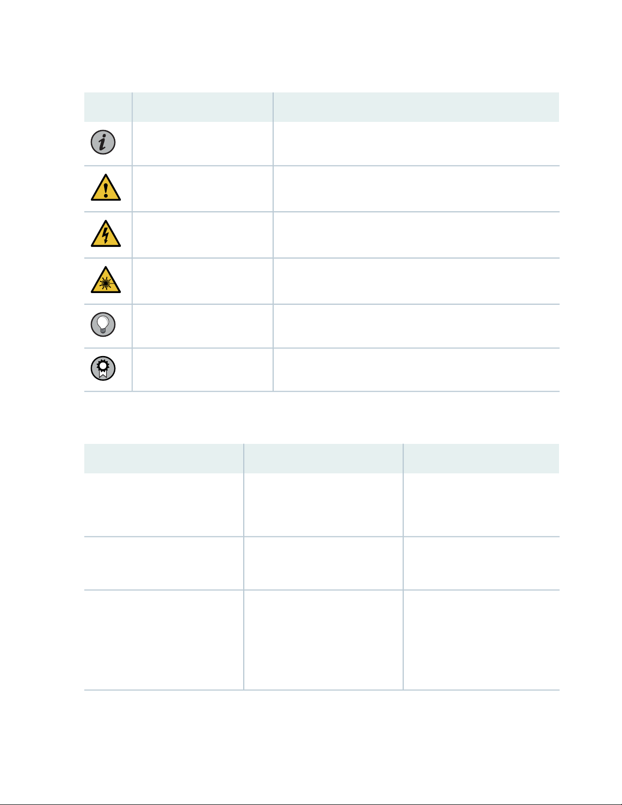
Table 1: Notice Icons
xv
DescriptionMeaningIcon
Indicates important features or instructions.Informational note
Caution
Indicates a situation that might result in loss of data or hardware
damage.
Alerts you to the risk of personal injury or death.Warning
Alerts you to the risk of personal injury from a laser.Laser warning
Indicates helpful information.Tip
Alerts you to a recommended use or implementation.Best practice
Table 2 on page xv defines the text and syntax conventions used in this guide.
Table 2: Text and Syntax Conventions
ExamplesDescriptionConvention
Fixed-width text like this
Italic text like this
Represents text that you type.Bold text like this
Represents output that appears on
the terminal screen.
Introduces or emphasizes important
•
new terms.
Identifies guide names.
•
Identifies RFC and Internet draft
•
titles.
To enter configuration mode, type
the configure command:
user@host> configure
user@host> show chassis alarms
No alarms currently active
A policy term is a named structure
•
that defines match conditions and
actions.
Junos OS CLI User Guide
•
RFC 1997, BGP Communities
•
Attribute
Page 16

Table 2: Text and Syntax Conventions (continued)
xvi
ExamplesDescriptionConvention
Italic text like this
Text like this
< > (angle brackets)
| (pipe symbol)
Represents variables (options for
which you substitute a value) in
commands or configuration
statements.
Represents names of configuration
statements, commands, files, and
directories; configuration hierarchy
levels; or labels on routing platform
components.
variables.
Indicates a choice between the
mutually exclusive keywords or
variables on either side of the symbol.
The set of choices is often enclosed
in parentheses for clarity.
Configure the machine’s domain
name:
[edit]
root@# set system domain-name
domain-name
To configure a stub area, include
•
the stub statement at the [edit
protocols ospf area area-id]
hierarchy level.
The console port is labeled
•
CONSOLE.
stub <default-metric metric>;Encloses optional keywords or
broadcast | multicast
(string1 | string2 | string3)
# (pound sign)
[ ] (square brackets)
Indention and braces ( { } )
; (semicolon)
GUI Conventions
Indicates a comment specified on the
same line as the configuration
statement to which it applies.
Encloses a variable for which you can
substitute one or more values.
Identifies a level in the configuration
hierarchy.
Identifies a leaf statement at a
configuration hierarchy level.
rsvp { # Required for dynamic MPLS
only
community name members [
community-ids ]
[edit]
routing-options {
static {
route default {
nexthop address;
retain;
}
}
}
Page 17
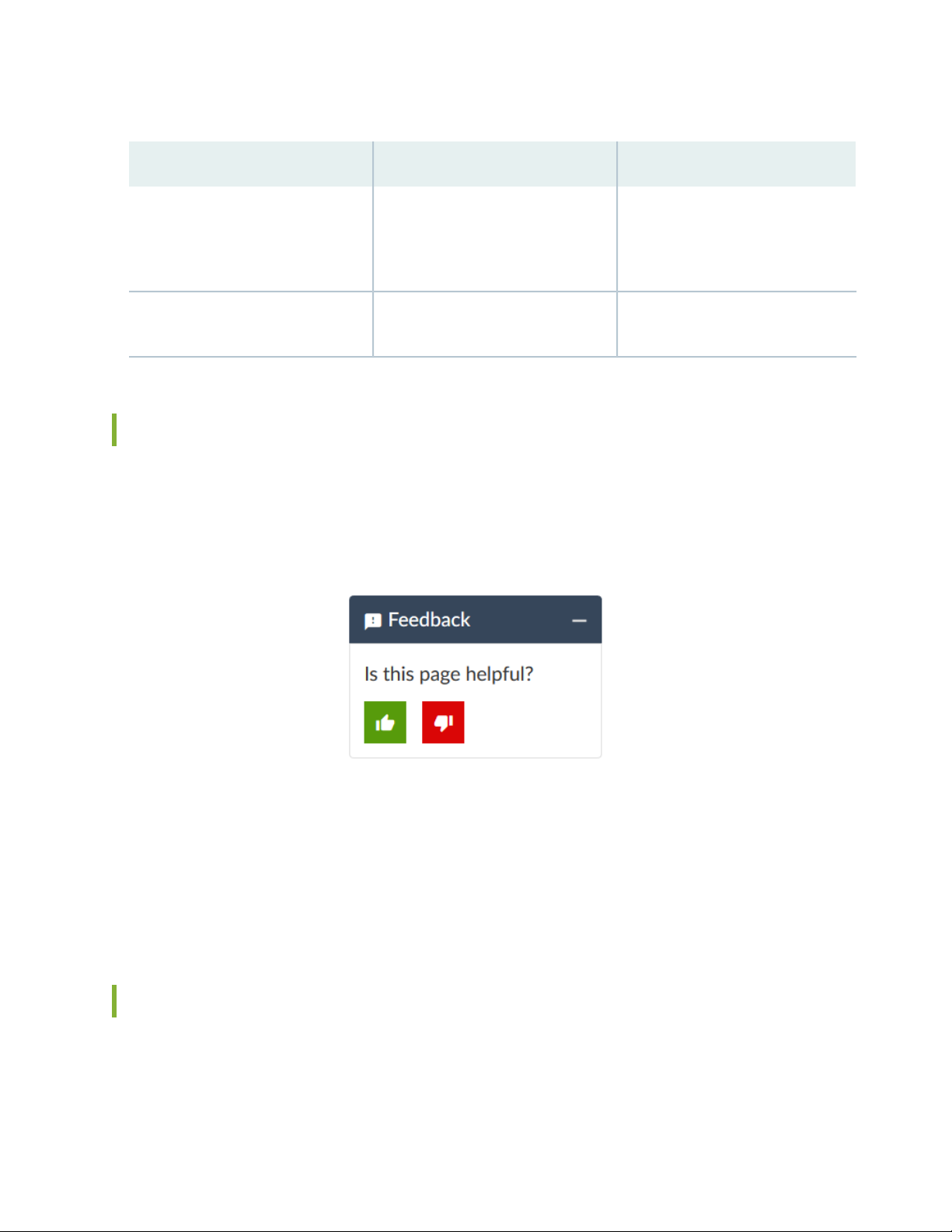
Table 2: Text and Syntax Conventions (continued)
xvii
ExamplesDescriptionConvention
Bold text like this
> (bold right angle bracket)
Represents graphical user interface
(GUI) items you click or select.
Separates levels in a hierarchy of
menu selections.
In the Logical Interfaces box, select
•
All Interfaces.
To cancel the configuration, click
•
Cancel.
In the configuration editor hierarchy,
select Protocols>Ospf.
Documentation Feedback
We encourage you to provide feedback so that we can improve our documentation. You can use either
of the following methods:
Online feedback system—Click TechLibrary Feedback, on the lower right of any page on the Juniper
•
Networks TechLibrary site, and do one of the following:
Click the thumbs-up icon if the information on the page was helpful to you.
•
Click the thumbs-down icon if the information on the page was not helpful to you or if you have
•
suggestions for improvement, and use the pop-up form to provide feedback.
E-mail—Send your comments to techpubs-comments@juniper.net. Include the document or topic name,
•
URL or page number, and software version (if applicable).
Requesting Technical Support
Technical product support is available through the Juniper Networks Technical Assistance Center (JTAC).
If you are a customer with an active Juniper Care or Partner Support Services support contract, or are
Page 18

covered under warranty, and need post-sales technical support, you can access our tools and resources
online or open a case with JTAC.
JTAC policies—For a complete understanding of our JTAC procedures and policies, review the JTAC User
•
Guide located at https://www.juniper.net/us/en/local/pdf/resource-guides/7100059-en.pdf.
Product warranties—For product warranty information, visit https://www.juniper.net/support/warranty/.
•
JTAC hours of operation—The JTAC centers have resources available 24 hours a day, 7 days a week,
•
365 days a year.
Self-Help Online Tools and Resources
For quick and easy problem resolution, Juniper Networks has designed an online self-service portal called
the Customer Support Center (CSC) that provides you with the following features:
Find CSC offerings: https://www.juniper.net/customers/support/
•
Search for known bugs: https://prsearch.juniper.net/
•
xviii
Find product documentation: https://www.juniper.net/documentation/
•
Find solutions and answer questions using our Knowledge Base: https://kb.juniper.net/
•
Download the latest versions of software and review release notes:
•
https://www.juniper.net/customers/csc/software/
Search technical bulletins for relevant hardware and software notifications:
•
https://kb.juniper.net/InfoCenter/
Join and participate in the Juniper Networks Community Forum:
•
https://www.juniper.net/company/communities/
Create a service request online: https://myjuniper.juniper.net
•
To verify service entitlement by product serial number, use our Serial Number Entitlement (SNE) Tool:
https://entitlementsearch.juniper.net/entitlementsearch/
Creating a Service Request with JTAC
You can create a service request with JTAC on the Web or by telephone.
Visit https://myjuniper.juniper.net.
•
Call 1-888-314-JTAC (1-888-314-5822 toll-free in the USA, Canada, and Mexico).
•
For international or direct-dial options in countries without toll-free numbers, see
https://support.juniper.net/support/requesting-support/.
Page 19

1
CHAPTER
Overview
MX104 Universal Routing Platform Overview | 20
MX104 Chassis | 22
MX104 Cooling System and Airflow Overview | 31
MX104 Power System | 32
MX104 Host Subsystem | 42
MX104 Interface Modules | 46
Page 20

MX104 Universal Routing Platform Overview
The Juniper Networks MX104 Universal Routing Platform is optimized for aggregating mobile, enterprise
WAN, business, and residential access services. The MX104 router is designed for high-density access
and pre-aggregation and is environmentally hardened to allow outside deployments in cabinets and remote
terminals. The router is a high-performance router functioning as a universal aggregation platform for
mobile broadband and metro Ethernet applications. It also acts as a universal edge platform supporting all
types of private WAN, data center interconnect, Internet edge, business edge, and residential edge services.
The router is powered by the Junos Trio chipset and runs the Junos®operating system (Junos OS) for
high-performance routing and switching. For a list of related Junos OS documentation, see
https://www.juniper.net/documentation/software/junos/.
Benefits of MX104 Router
20
System Capacity—MX104 provides 80 Gbps of throughput. MX104 has four Modular Interface Card
•
(MIC) slots and supports redundant fixed 10-Gigabit Ethernet interfaces for flexible network connectivity.
The Programmable Chipset—The chipset implemented in the MX Series routers has a programmable
•
forwarding data structure that allows fast microcode changes in the hardware itself, and a programmable
lookup engine that allows inline service processing. the chip’s programmable QoS engine supports coarse
and fine-grained queuing to address the requirements of core, edge, and aggregation use cases.
Always-on infrastructure base—MX Series routers ensure network and service availability with a broad
•
set of multilayered physical, logical, and protocol-level resiliency aspects. Junos OS Virtual Chassis
technology on MX Series routers supports chassis-level redundancy and enables you to manage two
routers as a single element. Multichassis link aggregation group (MC-LAG) implementation supports
stateful chassis, card, and port redundancy.
Application-Aware Networking—On MX Series routers you can use deep packet inspection to detect
•
applications, and by using the user-defined policies, you can determine traffic treatment for each
application. This feature enables highly customized and differentiated services at scale.
Junos Continuity and Unified In-Service Software Upgrade (Unified ISSU)—With the Junos continuity
•
plug-in package, you can perform a smooth upgrade when new hardware is installed in your MX Series
router.
Unified in-service software upgrade (unified ISSU) enables software upgrades and changes without
disrupting network traffic.
Junos Telemetry Interface—Using the Junos telemetry interface data, you can stream component-level
•
data to monitor, analyze, and enhance the performance of the network. Analytics derived from this
Page 21
streaming telemetry can identify current and trending congestion, resource utilization, traffic volume,
g007600
and buffer occupancy.
Integrated Hardware-Based Timing— You do not need to use external clocks because MX Series routers
•
support highly scalable and reliable hardware-based timing, including Synchronous Ethernet for frequency,
and the Precision Time Protocol (PTP) for frequency and phase synchronization. Synchronous Ethernet
and PTP can be combined in a hybrid mode to achieve a high level of frequency (10 ppb) and phase (<1.5
uS) accuracy.
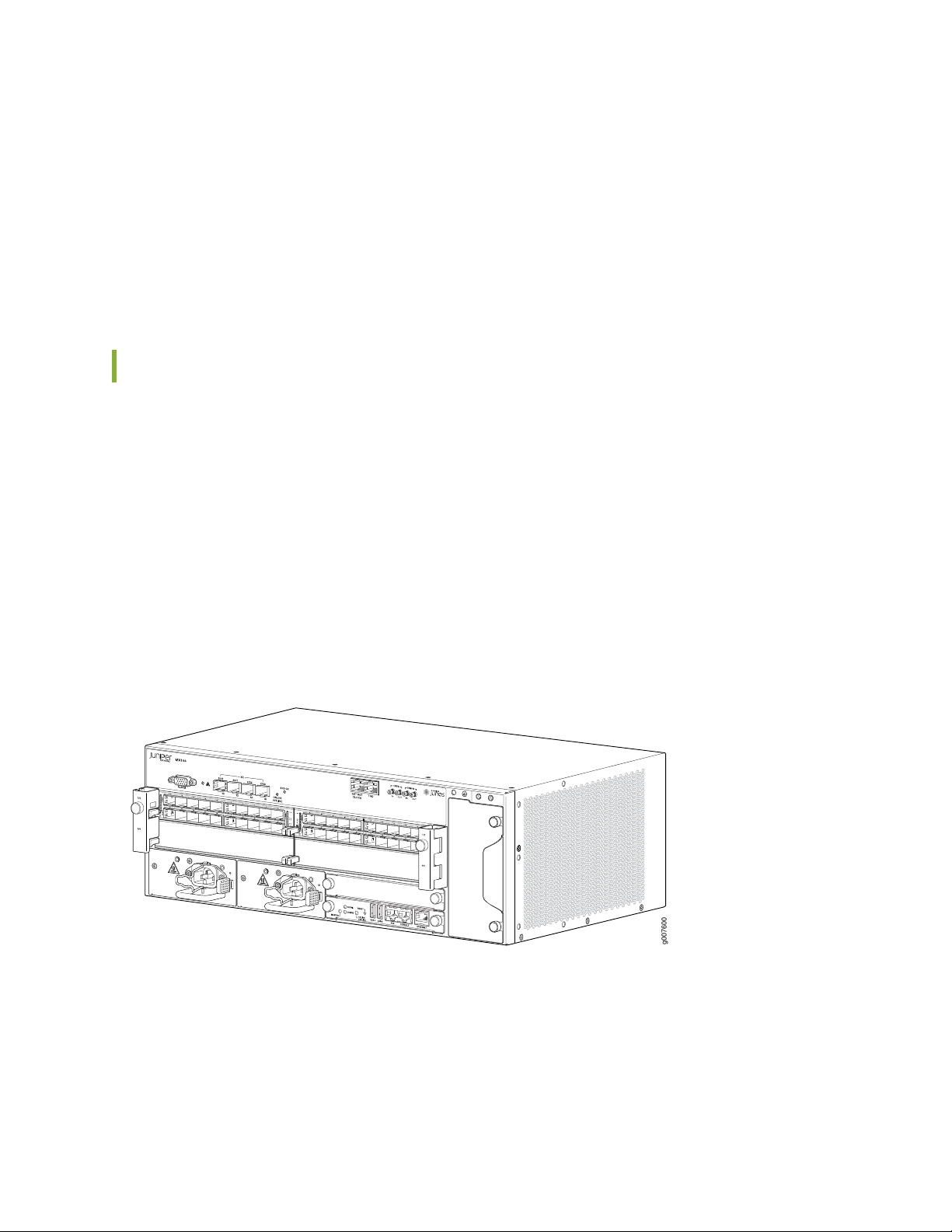
System Overview
The chassis is a rigid sheet metal structure that houses all the other router components (see
Figure 1 on page 21 and Figure 2 on page 22). The hardware system provides resiliency and redundancy,
including power supplies and Routing Engines. The chassis also has four built-in 10-Gigabit Ethernet SFP+
ports and four slots that accept Modular Interface Cards (MICs). For a list of the supported MICs, see the
MX Series Interface Module Reference.
21
The router is environmentally hardened and is 3.5 rack units (U; that is, 6.125 in., or 15.55 cm) tall. Several
routers can be stacked in a single floor-to-ceiling rack, for increased port density per unit of floor space.
The chassis is installed in standard 11.81 in. (30 cm)-deep (or larger) enclosed cabinets, 19-in. equipment
racks, or telco open-frame racks.
Figure 1: Front Panel of the MX104 Router
Page 22
Figure 2: Rear View of the MX104 Router
RELATED DOCUMENTATION
MX104 Port and Interface Numbering | 49
22
MX104 Chassis
IN THIS SECTION
MX104 Chassis Overview | 22
MX104 Hardware and CLI Terminology Mapping | 24
MX104 Component Redundancy | 26
MX104 Alarm Contact Port Overview | 26
MX104 LEDs Overview | 28
MX104 Chassis Overview
The MX104 router contains a front panel with slots in which you can install field-replaceable units (FRUs).
From the front of the chassis, you can see the following components (see Figure 3 on page 24):
Alarm console port labeled ALARM, which accepts a DE-15 alarm cable.
•
Alarm LEDs that indicate major or minor alarms.
•
Built-in 10-Gigabit Ethernet MIC with four ports that accept 10-Gigabit Ethernet SFP+ transceivers.
•
Page 23

ONLINE/OFFLINE button.
•
Chassis status LED labeled SYS OK
•
External building integrated timing system (BITS) port labeled EXT REF CLOCK
•
Time-of-day (TOD) port
•
External clocking ports supporting 1-PPS and 10-MHz input and output
•
ESD point
•
Fan tray, which contains five fans and an air filter
•
Four slots for installing MICs
•
NOTE: For a detailed description of the MX104 port and interface numbering see “MX104
Port and Interface Numbering” on page 49.
Two slots for installing either AC or DC power supplies, labeled PS 0 and PS 1
•
23
Two slots for installing Routing Engines, labeled RE 0 and RE 1
•
Page 24
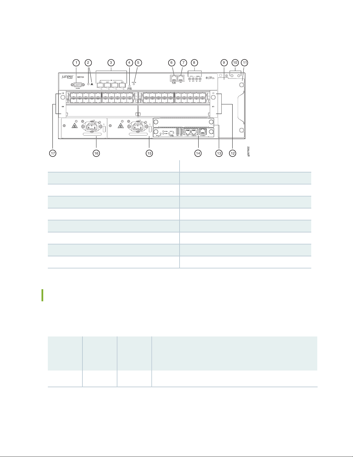
Figure 3: Front View of the MX104 Router
g007602
17 16 15 1314 12
31 54 10 1198762
24
10—1— Grounding terminalsAlarm input and output contacts
11—2— Fan trayAlarm LEDs
12—3— MIC slots 0/1 and 1/110-Gigabit Ethernet SFP+ ports
13—4— Routing Engine slot 1Online/offline button
14—5— Routing Engine slot 0System status LED
15—6— Power supply slot 1External reference clocking port
16—7— Power supply slot 0Time-of-day (ToD) port
17—8— MIC slots 0/0 and 1/01-PPS and 10-MHz GPS input and output ports
9—ESD point
MX104 Hardware and CLI Terminology Mapping
The MX104 router supports the components in Table 3 on page 24, listed in alphabetic order.
Table 3: MX104 Routers Hardware Components and CLI Terminology
Hardware
Model
NumberComponent
DescriptionCLI Name
“MX104 Universal Routing Platform Overview” on page 20MX104N/AChassis
Page 25

Table 3: MX104 Routers Hardware Components and CLI Terminology (continued)
Hardware
Model
NumberComponent
filters
N/AFLTR-KIT-MX104Air filter kit
Fan TrayFANTRAY-MX104Fan tray
N/APWR-BLANK-MX104Power blank
cover
DescriptionCLI Name
“MX104 Cooling System and Airflow Overview” on page 31Cooling system, including fan trays and air
“MX104 Power Overview” on page 33Power system components
25
Power
supply
MIC
MPC
Engine
Transceiver
AC:
•
PWR-MX104-AC
DC:
•
PWR-MX104-DC
N/A
(built-in)
Module Reference.
(built-in)
RE-S-MX104Routing
Series
Interface
Module
Reference.
PEM
10GE(LAN)
SFP+
Engine
“MX104 Modular Interface Card (MIC) Overview” on page 464x
“MX104 Modular Interface Card (MIC) Overview” on page 46See MX Series Interface
“MX104 Modular Interface Card (MIC) Overview” on page 46FPCN/A
“MX104 Routing Engine Overview” on page 42Routing
“MX104 Modular Interface Card (MIC) Overview” on page 46XcvrSee MX
SEE ALSO
Page 26

MX104 Port and Interface Numbering | 49
MX104 Component Redundancy
The MX104 chassis provides redundancy and resiliency. The hardware system is fully redundant, including
power supplies, Routing Engines, and cooling system.
A fully configured router is designed so that no single point of failure can cause the entire system to fail.
Only a fully configured router provides complete redundancy. All other configurations provide partial
redundancy. The following major hardware components are redundant:
Power supplies—In a redundant configuration, the router contains either two AC or DC power supplies
•
that install into the front of the chassis. The slots are labeled PS 0 and PS 1 (left to right). Each power
supply provides power to all components in the router. When two power supplies are present, they
share power almost equally within a fully populated system. If one power supply in a redundant
configuration fails or is removed, the remaining power supplies assume the entire electrical load without
interruption. Two power supplies provide the maximum configuration with full power for as long as the
router is operational.
26
Routing Engine—If two Routing Engines are installed, one functions as the primary and the other functions
•
as the backup. If the primary Routing Engine fails, the backup can take over as the primary.
Cooling system—The cooling system has redundant components, which are controlled by the host
•
subsystem. If one of the fans fails, the host subsystem increases the speed of the remaining fans to
provide sufficient cooling for the router indefinitely.
MX104 Alarm Contact Port Overview
The MX104 router has four external alarm contacts (also known as potential free contacts) for connecting
the router to external alarm devices. The port labeled ALARM uses a 15-pin D-type connector. The external
alarm contact has 15 pins that accept a single core wire from external alarm devices. A DE-15 alarm cable
is required to connect the MX104 router to external alarm devices. Use the gauge wire appropriate for
the external device that you are connecting.
Whenever a system condition triggers an alarm, the alarm relay contacts are activated, which in turn
activates the external alarm devices. The alarm setting is open or closed.
You can connect and configure two output alarms and four input alarms. Two additional output alarms
are reserved and are used to indicate major and minor system alarms. Each output and input alarm has
two contacts for connecting the router to external alarm devices. Contact 1 of each alarm can be configured
as Normally Open [NO] or Normally Closed [NC] through the CLI. Contact 2 of each alarm functions as a
Page 27
reference [REF] or negative potential terminal for Contact 1 of the corresponding alarm and provides a
current path for external alarm devices. Table 4 on page 27 describes the functions of the alarm contacts.
Table 4: Alarm Relay Contact Functions
FunctionContact NameContact Name
27
Normally Open [NO]Contact 1
Normally Closed [NC]
Reference [REF]Contact 2
Current is not flowing through Contact 1 and Contact 2 [REF] when
operating normally. When the current flows, the closed alarm is
generated.
Current is flowing through Contact 1 and Contact 2 [REF] when
operating normally. When the current stops flowing, the open alarm
is generated.
Provides the current path for the external alarm-reporting device
and functions as a reference or negative potential terminal for
Contact 1.
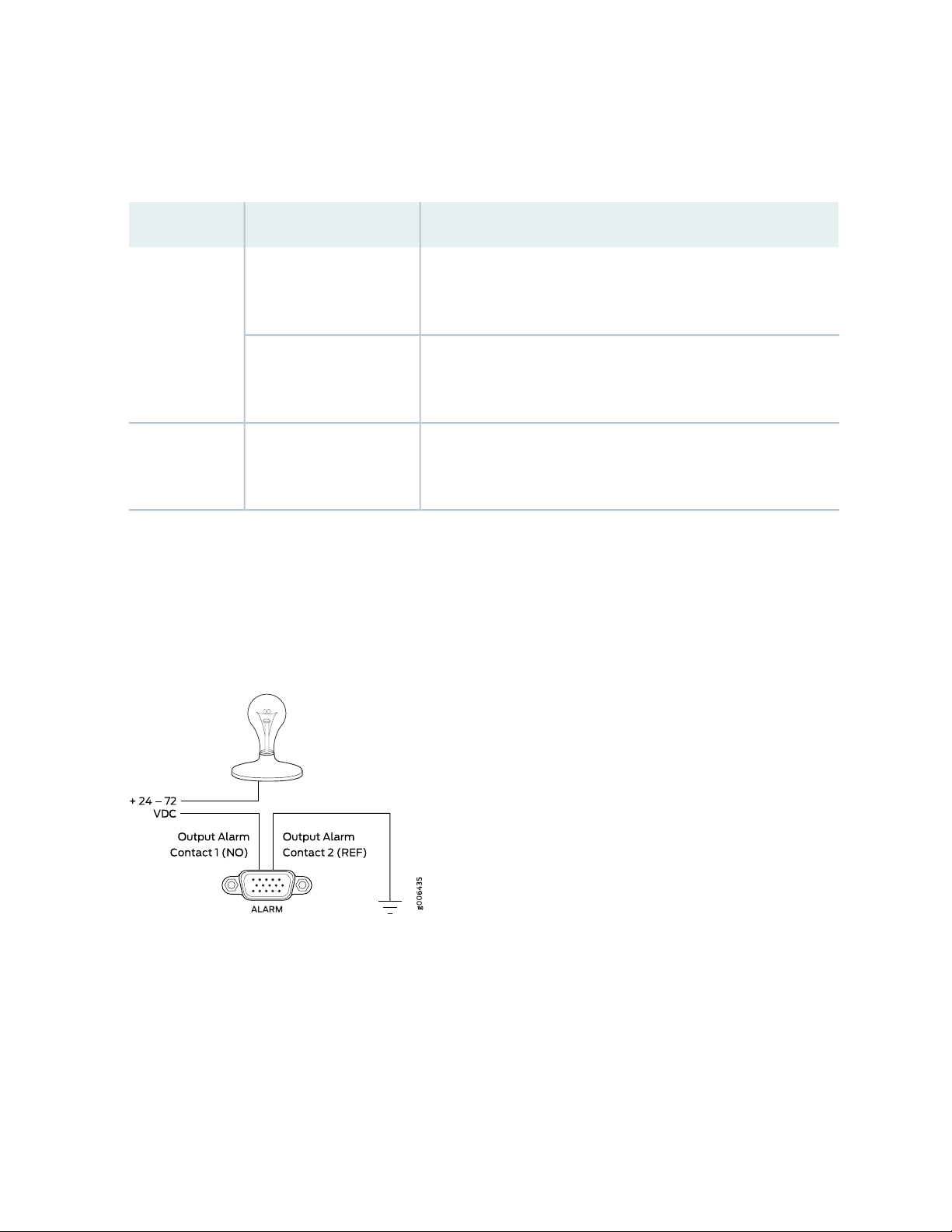
Figure 4 on page 27 shows an example of a wiring diagram for a simple output alarm-reporting device. In
this case, the device is a light bulb that illuminates when the device encounters a condition that activates
the red alarm LED and relay contacts. The alarm relay contacts can also be used to activate other devices
such as bells or buzzers.
Figure 4: Sample Output Alarm-Reporting Device
Figure 5 on page 28 shows an example of a wiring diagram for a simple input alarm-reporting device. In
this case, the push button switch is an alarm sensor that triggers an input alarm when a door-open condition
occurs.
Page 28
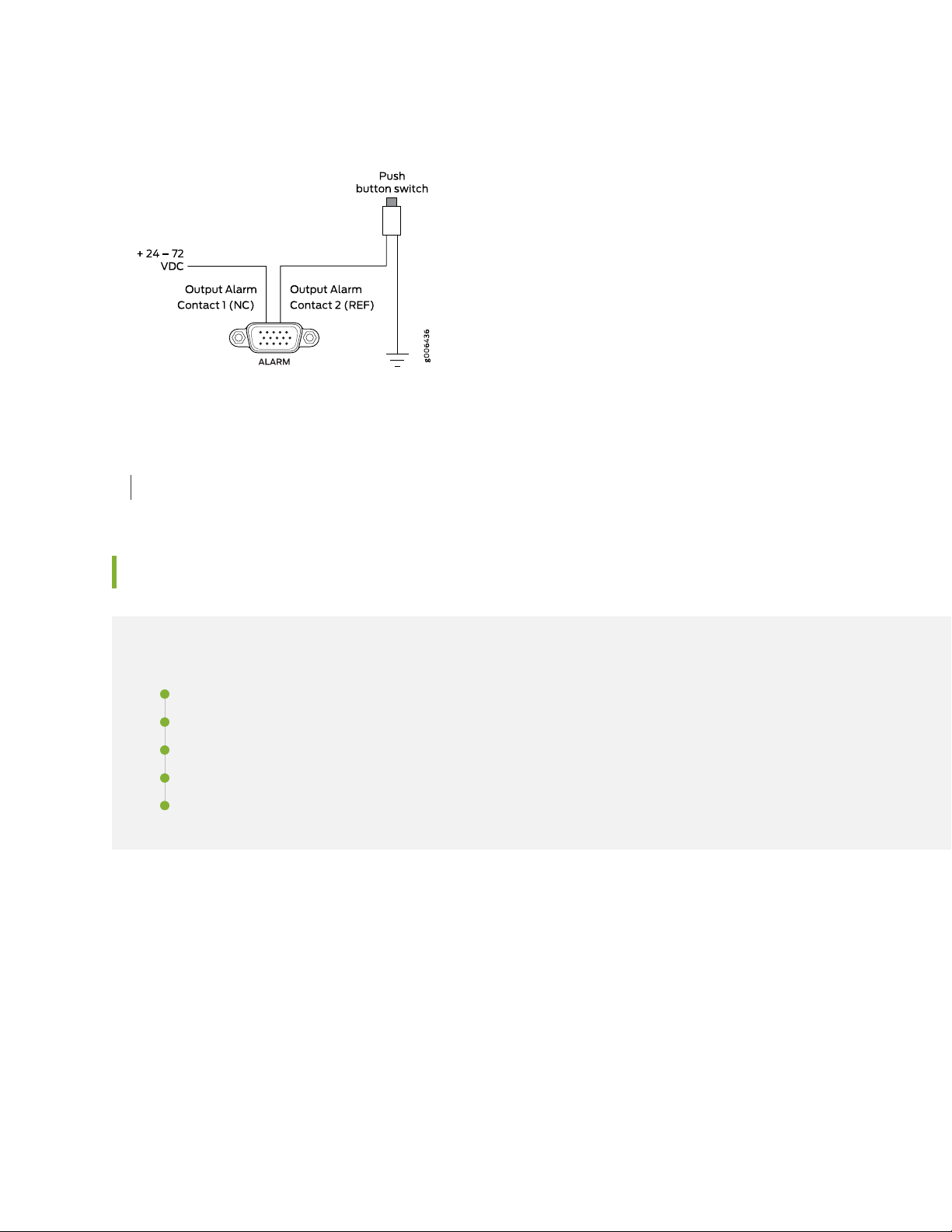
Figure 5: Sample Input Alarm-Reporting Device
SEE ALSO
MX104 Alarm Contact Port Specifications | 77
28
MX104 LEDs Overview
IN THIS SECTION
Alarm LEDs on the Front Panel | 28
System LED on the Front Panel | 29
MIC LEDs | 30
Power Supply LED | 30
Routing Engine LEDs | 30
Alarm LEDs on the Front Panel
Two LEDs, located to the right of the alarm contact port indicates major and minor alarms for the router
(see Figure 6 on page 29).
Page 29
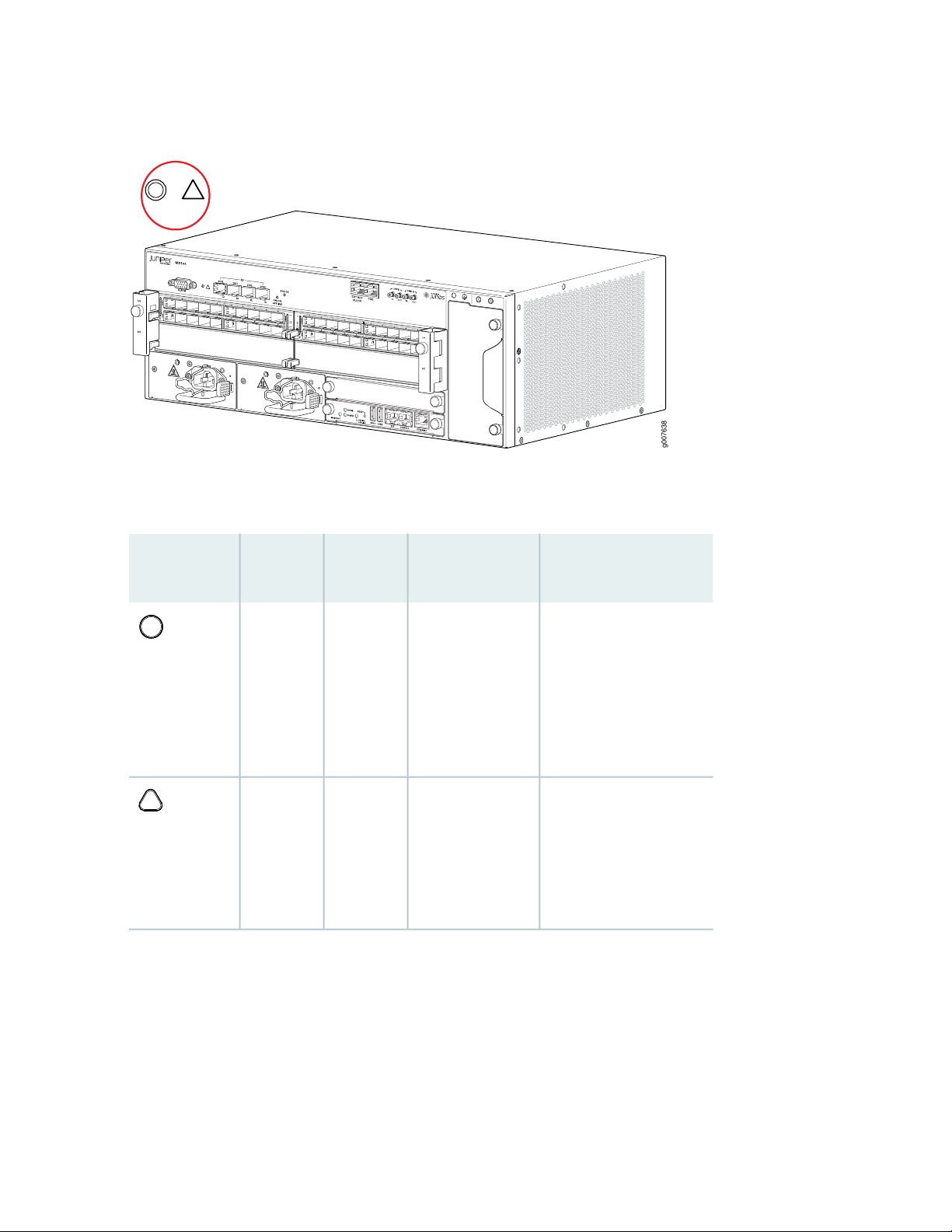
Figure 6: Alarm LEDs on the MX104 Router
g007638
Table 5 on page 29 describes the alarm LED in more detail.
29
Table 5: Alarm LEDs on the Front Panel
Red
steadily
Yellow
steadily
LED Control
NameStateColorShape
Critical alarmOn
Warning alarmOn
Description
Indicates a critical
condition that can cause
the router to stop
functioning. Possible
causes include component
removal, failure, or
overheating.
Indicates a serious but
nonfatal error condition,
such as a maintenance
alert or a significant
increase in component
temperature.
System LED on the Front Panel
One bicolor LED labeled SYS OK indicates the status of the router. Table 6 on page 30 describes the
system LED in more detail.
Page 30

Table 6: System LED on the Front Panel
DescriptionStateColorLabel
Router has no primary Routing Engine.BlinkingGreenSYS OK
Router is functioning normally.On
steadily
30
Yellow
steadily
Red
steadily
Router has reported a minor alarm.On
Router has failed.On
MIC LEDs
Each hot-removable and hot-insertable MIC has LEDs located on the faceplate. For more information
about LEDs on the MIC faceplate, see the “LEDs” section for each MIC in the MX Series Interface Module
Reference.
For information about the built-in MIC LEDs, see “MX104 Modular Interface Card (MIC) Overview” on
page 46.
Power Supply LED
One LED labeled PS STATUS indicates the status of the power supply. For more information, see “MX104
Power Overview” on page 33.
Routing Engine LEDs
Three LEDs indicate the status of the Routing Engine. For more information, see “MX104 Routing Engine
Overview” on page 42.
SEE ALSO
Troubleshooting Resources for MX104 Routers | 156
Page 31

MX104 Cooling System and Airflow Overview
g007621
The cooling system in an MX104 router consists of the following components (see Figure 7 on page 31):
Fan tray
•
Air filter
•
Figure 7: MX104 Fan Tray and Air Filter
31
The router has one hot-swappable fan tray that contains five fans. The air filter installs into the side of the
fan tray. The air intake to cool the chassis is located on the right side of the chassis next to the air filter.
Air is pulled through the air filter toward the fan tray, where it is exhausted out the left side of the system
(see Figure 8 on page 32). The exhaust for the power supplies is located on the left side of the chassis.
Page 32

Figure 8: Cooling System and Airflow in an MX104 Router
g0 0 7633
Minimum
cl earan ce
Minimum
cl earan ce
6 in .
(15.2 cm)
6 in .
(15.2 cm)
Front vi ew
Fan t ray
Air fi lter
Pow er suppli es
The cooling system components work together to keep all router components within the acceptable
temperature range. The chassis monitors the temperature of the router components. When the router is
operating normally, the fans function at lower than full speed. If a fan fails or the ambient temperature
rises above a threshold, the speed of the remaining fans is automatically adjusted to keep the temperature
within the acceptable range. If the ambient maximum temperature specification is exceeded and the system
cannot be adequately cooled, the Routing Engine shuts down the system by disabling output power from
each power supply.
32
RELATED DOCUMENTATION
Preparing the Site for the MX104 Router Overview | 57
Maintaining the MX104 Air Filter | 122
Rack Requirements for MX104 Routers | 64
Cabinet Requirements for MX104 Routers | 65
Clearance Requirements for Airflow and Hardware Maintenance on MX104 Routers | 67
MX104 Router Environmental Specifications | 59
MX104 Power System
IN THIS SECTION
MX104 Power Overview | 33
MX104 Power Consumption | 35
MX104 AC Power Specifications | 36
Page 33

MX104 AC Power Cord Specifications | 37
MX104 DC Power Specifications | 39
MX104 DC Power Cable and Lug Specifications | 40
MX104 Power Overview
IN THIS SECTION
AC Power Supplies | 33
DC Power Supplies | 34
Power Supply LEDs | 35
33
The MX104 router uses either AC or DC power supplies (see Figure 9 on page 34 and Figure 10 on page 34).
The power supplies are located in the front of the chassis and offer 1+1 redundancy. Each power supply
has a handle, an ejection tab, and a status LED.
CAUTION: The router cannot be powered from AC and DC power supplies
simultaneously.
When two power supplies are present, they share power almost equally within a fully populated system.
If one power supply in a redundant configuration fails or is removed, the remaining power supply assumes
the entire electrical load without interruption. A single power supply provides the maximum configuration
with full power for as long as the router is operational. A second power supply can be installed for
redundancy. Each power supply is cooled by its own internal cooling system.
Redundant power supplies are hot-removable and hot-insertable. When you remove a power supply from
a router that uses only one power supply, the router might shut down depending on your configuration.
AC Power Supplies
Each AC power supply weighs approximately 2.5 lb (1.13 kg) and consists of a handle, a power cord retainer
clip, an ejection latch, an AC appliance inlet, a fan, and an LED to monitor the status of the power supply.
Figure 9 on page 34 shows the power supply.
Page 34

Each inlet requires a dedicated AC power feed and a dedicated customer site circuit breaker. We recommend
g0 0 76 03
g0 0 760 9
that you use a dedicated customer site circuit breaker rated for 10 A (100 VAC), or as required by local
code.
Figure 9: AC Power Supply
WARNING: The router is pluggable type A equipment installed in a restricted-access
location. It has a separate protective earthing terminal (sized for SAE 10-32 ground
screws) provided on the chassis in addition to the grounding pin of the power supply
cord. This separate protective earthing terminal must be permanently connected to
earth.
34
DC Power Supplies
Each DC power supply weighs approximately 3 lb (1.36 kg) and consists of a handle, an ejection latch, a
status LED, a grounding point, and a terminal block that provides a single DC input (24, –48, or –60 VDC
and return) that requires a dedicated customer site circuit breaker. We recommend that you provide at
least 40 A @ 24 VDC and use a facility circuit breaker. Figure 10 on page 34 shows the power supply.
Figure 10: DC Power Supply
Page 35

Power Supply LEDs
One LED labeled PS STATUS indicates the status of the power supply. Table 7 on page 35 describes the
system LED in more detail.
Table 7: Power Supply LED
DescriptionStateColorLabel
35
Power supply is functioning normally, and input voltage is within allowable
operating range.
Primary OTPOn
Secondary OTPBlinking
Power supply is receiving input voltage below the allowable operating
range, but the redundant power supply is functioning normally.
Power supply is receiving input voltage below the allowable operating
range and is not part of a redundant configuration.
STATUS
GreenPS
Yellow
Red
On
steadily
steadily
On
steadily
Off—
SEE ALSO
Connecting AC Power Cords to the MX104 Router | 94
Connecting DC Power Cables to the MX104 Router | 95
MX104 Power Consumption
The MX104 router supports installation of up to two AC or DC power supplies in slots labeled on the front
of the router.
Table 8 on page 36 lists the power consumed by the MX104 router.
NOTE: The power consumption values are measured from the power source and are based on
systems that contain redundant power supplies, redundant Routing Engines, a fan tray, and are
fully loaded with MICs.
Page 36

Table 8: Power Consumed by MX104 Routers
SEE ALSO
Connecting DC Power Cables to the MX104 Router | 95
MX104 DC Power Electrical Safety Guidelines | 208
36
ValueDescription
600 WPower consumed by the AC router (typical)
625 WPower consumed by the DC router (typical)
325 WPower consumed by the AC router without MICs (typical)
350 WPower consumed by the DC router without MICs (typical)
MX104 AC Power Specifications
Table 9 on page 36 lists the AC power electrical specifications.
Table 9: AC Power Electrical Specifications
SpecificationItem
Power Supplies
Operating range: 100 to 240 VACAC input voltage
50 to 60 Hz (nominal)AC input line frequency
10 A maximum per inlet at 100 VACAC input current rating
91% @ 800 W@ 230 VEfficiency
800 WMaximum AC power
supply output power
System
800 WMaximum output power
Page 37

NOTE: We recommend that you use a facility circuit breaker rated for 10 A maximum per inlet
at 100 VAC to 240 VAC. Doing so enables you to operate the router in any configuration without
upgrading the power infrastructure, and allows the router to function at full capacity using
multiple power supplies.
SEE ALSO
Connecting AC Power Cords to the MX104 Router | 94
Replacing an MX104 AC Power Supply | 144
MX104 AC Power Electrical Safety Guidelines and Warnings | 207
37
MX104 AC Power Cord Specifications
Each AC power supply has a single AC appliance inlet that requires a dedicated AC power feed. Most sites
distribute power through a main conduit that leads to frame-mounted power distribution panels, one of
which can be located at the top of the rack that houses the router. An AC power cord connects each power
supply to the power distribution panel.
You can order detachable AC power cords, each approximately 8 ft (2.5 m) long that supply AC power to
the router. The C15 appliance coupler at the socket end of the cord, as described by International
Electrotechnical Commission (IEC) standard 60320, inserts into the AC appliance inlet coupler. The plug
end of the power cord fits into the power source receptacle that is standard for your geographic location.
Table 10 on page 37 provides specifications on the AC power cord provided for each country or region.
Table 10: AC Power Cord Specifications
Design StandardPlug TypeElectrical SpecificationModel NumberCountry
IRAM 2073RA/3250 VAC, 10 A, 50 HzCBL-PWR-C15M-HITEMP-ARArgentina
SAA/3250 VAC, 10 A, 50 HzCBL-PWR-C15M-HITEMP-AUAustralia
AS/NZZS
3112-2000
NBR 14136BR/3250 VAC, 10 A, 50 HzCBL-PWR-C15M-HITEMP-BRBrazil
GB2099, GB1002PRC/3250 VAC, 10 A, 50 HzCBL-PWR-C15M-HITEMP-CHChina
Page 38

Table 10: AC Power Cord Specifications (continued)
Italy, Switzerland,
and United
Kingdom)
38
Design StandardPlug TypeElectrical SpecificationModel NumberCountry
CEE (7) VIIVIIG250 VAC, 10 A, 50 HzCBL-PWR-C15M-HITEMP-EUEurope (except
SABS 164/1:1992ZA/3250 VAC, 10 A, 50 HzCBL-PWR-C15M-HITEMP-INIndia
SI 32IL/3G250 VAC, 10 A, 50 HzCBL-PWR-C15M-HITEMP-ILIsrael
CEI 23–16I/3G250 VAC, 10 A, 50 HzCBL-PWR-C15M-HITEMP-ITItaly
CBL-PWR-C15M-HITEMP-JPJapan
60 Hz
JIS 8303498GJ125 VAC, 15 A, 50 Hz or
CEE (7) VIIVIIG250 VAC, 10 A, 50 HzCBL-PWR-C15M-HITEMP-KRKorea
SABS 164/1:1992ZA/3250 VAC, 10 A, 50 HzCBL-PWR-C15M-HITEMP-SASouth Africa
SEV 1011 / 6534-212G250 VAC, 10 A, 50 HzCBL-PWR-C15M-HITEMP-SZSwitzerland
NEMA 5-15498G125 VAC, 13 A, 60 HzCBL-PWR-C15M-HITEMP-USNorth America
BS 1363/ABS89/13250 VAC, 10 A, 50 HzCBL-PWR-C15M-HITEMP-UKUnited Kingdom
WARNING: The attached power cable is only for this product. Do not use the cable
for another product. Translation in Japanese follows:
Page 39

NOTE: In North America, AC power cords must not exceed approximately 14.75 ft (4.5 m) in
length, to comply with National Electrical Code (NEC) Sections 400-8 (NFPA 75, 5-2.2) and
210-52, and Canadian Electrical Code (CEC) Section 4-010(3). You can order AC power cords
that are in compliance.
CAUTION: Power cords and cables must not block access to device components or
drape where people could trip on them.
NOTE: Use power cords rated up to 149° F (65° C) for ambient temperatures up to 140° F (60°
C).
39
SEE ALSO
Connecting AC Power Cords to the MX104 Router | 94
Replacing an MX104 AC Power Supply | 144
MX104 AC Power Electrical Safety Guidelines and Warnings | 207
MX104 DC Power Specifications
The MX104 power supply contains DC power terminals to connect power to the router and supports the
specifications shown in Table 11 on page 39.
Table 11: DC Power Electrical Specifications
SpecificationItem
Power Supplies
DC input voltages
18 to 30 VDC; nominal 24 VDC
•
–39 to –56 VDC; nominal 48 VDC
•
–39 to –72 VDC; nominal 60 VDC
•
Page 40

Table 11: DC Power Electrical Specifications (continued)
SpecificationItem
40
DC input currents
40 A @ 24 VDC
•
20 A @ –48 VDC
•
15 A @ –60 VDC
•
800 WMaximum power supply output
System
800 WMaximum output power
Each DC power supply has a single DC input (24, –48, or –60 VDC and return) that requires a dedicated
circuit breaker. We recommend that you use a facility circuit breaker rated for 40 A @ 24 VDC. Doing so
enables you to operate the router in any configuration without upgrading the power infrastructure, and
allows the router to function at full capacity using multiple power supplies.
SEE ALSO
Connecting DC Power Cables to the MX104 Router | 95
Replacing an MX104 DC Power Supply | 148
MX104 DC Power Electrical Safety Guidelines | 208
DC Power Electrical Safety Warnings for Juniper Networks Devices | 209
MX104 DC Power Cable and Lug Specifications
IN THIS SECTION
DC Power Cable Lug Specifications | 41
DC Power Cable Specifications | 41
Page 41

DC Power Cable Lug Specifications
Use cable lugs with the specifications shown in Figure 11 on page 41 to attach each DC power cable to
the DC power supply.
Figure 11: DC Power Cable Lug
41
CAUTION: Before router installation begins, a licensed electrician must attach a cable
lug to the grounding and power cables that you supply. A cable with an incorrectly
attached lug can damage the router.
DC Power Cable Specifications
You must supply two DC power cables for each DC power supply that meet the following specifications:
14-AWG (2.08 mm2), minimum 90° C wire, or as required by the local code.
SEE ALSO
Connecting DC Power Cables to the MX104 Router | 95
Replacing an MX104 DC Power Supply | 148
MX104 DC Power Electrical Safety Guidelines | 208
DC Power Electrical Safety Warnings for Juniper Networks Devices | 209
Page 42

MX104 Host Subsystem
IN THIS SECTION
MX104 Routing Engine Overview | 42
MX104 Routing Engine Overview
IN THIS SECTION
MX104 Routing Engine Components | 43
42
MX104 Routing Engine Buttons | 44
MX104 Routing Engine LEDs | 44
MX104 Boot Sequence | 45
MX104 Routing Engine and its Specifications | 45
The Routing Engine is a Freescale-based PC platform that runs Junos OS. Software processes that run on
the Routing Engine maintain the routing tables, manage the routing protocols used on the router, control
the router interfaces, control some chassis components, and provide the interface for system management
and user access to the router.
You can install one or two Routing Engines in the router. The Routing Engine installs into the front of the
chassis. Two USB ports on the Routing Engine accept a USB memory card that allows you to load Junos
OS.
If two Routing Engines are installed, one functions as the primary and the other acts as the backup. If the
primary Routing Engine fails or is removed and the backup is configured appropriately, the backup takes
over as the primary. The backup Routing Engine is hot-insertable and hot-removable.
The MX104 router supports the Routing Engine with model number RE-MX104.
Page 43

Figure 12: MX104 Routing Engine
g0 0 76 29
MX104 Routing Engine Components
Five ports, located on the right side of the Routing Engine, connect the Routing Engine to one or more
external devices on which system administrators can issue Junos OS command-line interface (CLI) commands
to manage the router.
The Routing Engine consists of the following components:
1.8-GHz CPU—Runs Junos OS to maintain the router's routing tables and routing protocols.
•
4-GB DDR3 RAM (mini DIMM)—Provides storage for the routing and forwarding tables and for other
•
Routing Engine processes.
43
8-GB on-board NAND Flash—Provides primary storage for software images, configuration files, and
•
microcode. The NAND flash is fixed and is inaccessible from outside the router.
Interface ports—Provides access to management devices.
•
AUX—Not supported.
•
CONSOLE—Connects the Routing Engine to a system console through a serial cable with an RJ-45
•
connector.
ETHERNET—Connects the Routing Engine through an Ethernet connection to a management LAN (or
•
any other device that plugs into an Ethernet connection). The port uses an autosensing RJ-45 connector
to support 10-Mbps, 100-Mbps, or 1000-Mbps connections. Two small LEDs on the right of the port
indicate the connection in use: see “MX104 Routing Engine LEDs” on page 44.
Two USB ports—Provide a removable media interface through which you can install the Junos OS
•
manually. Junos OS supports USB version 1.0.
Online/Offline button—Takes the Routing Engine online or offline when pressed (see “MX104 Routing
•
Engine Buttons” on page 44).
Reset button—Reboots the Routing Engine when pressed (see “MX104 Routing Engine Buttons” on
•
page 44).
LEDs—Indicates the status of the Routing Engine and its ports (see “MX104 Routing Engine LEDs” on
•
page 44)
Page 44

MX104 Routing Engine Buttons
Each Routing Engine has two push-button controls. The buttons, labeled ONLINE OFFLINE, and RESET,
are located directly on the faceplate of the Routing Engine. Table 12 on page 44 describes the functions
of the buttons.
Table 12: MX104 Routing Engine Buttons
IndicatorDescriptionActionLabel
44
ONLINE
OFFLINE
RESET
Press for 2
seconds.
Press for 4
seconds.
seconds.
pressed.
pressed.
Green ONLINE LED is on steadily.Routing Engine transitions online when
All LEDs are off.Routing Engine transitions offline when
Green ONLINE LED is on steadily.Routing Engine reboots when pressed.Press for 3
MX104 Routing Engine LEDs
Each Routing Engine has three LEDs that indicate its status. The LEDs, labeled MASTER, ONLINE, and
OK/FAIL, are located directly on the faceplate of the Routing Engine. Table 13 on page 44 describes the
functions of the Routing Engine LEDs.
Table 13: MX104 Routing Engine LEDs
DescriptionStateColorLabel
BlueMASTER
steadily
Routing Engine is the primary.On
GreenONLINE
steadily
GreenOK/FAIL
steadily
Red
steadily
Routing Engine is online.On
Routing Engine is booting.Blinking
Routing Engine is functioning normally.On
Routing Engine has failed.On
The management port labeled ETHERNET has a pair of LEDs that display the speed and status of the port.
Page 45

NOTE: The port labeled AUX is not supported.
Table 14 on page 45 describes the LEDs in more detail.
Table 14: Management LEDs
DescriptionStateColorLocationName
1000-Mbps link is online.OnGreenLeftLink
100-Mbps link is online.OnYellow
10-Mbps link is online.Off–
The port is receiving data.BlinkingYellowRightActivity
45
The port is not receiving data.Off–
MX104 Boot Sequence
The MX104 router ships with Junos OS preinstalled and ready to be configured when the router is powered
on. One eight-GB internal NAND Flash memory (da0) acts as the hard drive. Two USB ports on the front
panel accept USB storage devices (usb0 and usb1) that can also function as alternative boot devices.
When the router boots, it first attempts to start the image on the USB 0 flash memory device, if present,
then attempts to start the image on the USB 1 flash memory device, if present. If a USB flash memory
device is not inserted into either of the two slots on the Routing Engine, or the attempt otherwise fails,
the router next tries the active partition on the NAND Flash device.
MX104 Routing Engine and its Specifications
Table 15 on page 45 provides the details of the Routing Engine supported by the MX104 router.
Table 15: MX104 Routing Engine
Internal
Ethernet
Interface
Model
Number
Name in CLI
Output
First Supported
32-bit Junos OS
Release
First Supported
64-bit Junos OS
Release
Management
Ethernet
Interface
fxp0–13.2Routing EngineRE-S-MX104
em0
em1
Page 46

The specifications of the MX104 Routing Engine are as follows:
Processor—1.8-GHz
•
Memory—4 GB
•
Connection to PFEs—Gigabit Ethernet
•
Media—8 GB NAND Flash
•
SEE ALSO
Maintaining the MX104 Routing Engines | 126
Replacing an MX104 Routing Engine | 128
MX104 Routing Engines
Routing Engine Specifications
46
MX104 Interface Modules
IN THIS SECTION
MX104 Modular Interface Card (MIC) Overview | 46
MX104 Port and Interface Numbering | 49
MX104 Modular Interface Card (MIC) Overview
IN THIS SECTION
Front-Pluggable MICs | 47
Built-in 10-Gigabit Ethernet MIC | 47
MIC LEDs | 48
Page 47

MICs receive incoming packets from the network and transmit outgoing packets to the network. During
this process, each MIC performs framing and high-speed signaling for its media type. Before transmitting
outgoing data packets through the MIC interfaces, the Packet Forwarding Engine encapsulates the packets
received.
The MX104 routers support the following types of MICs:
Front-Pluggable MICs
Modular Interface Cards (MICs) install into four slots in the front of the MX104 router and provide the
physical connections to various network media types. MICs are hot-removable and hot-insertable. The
slots are labeled 0/0, 0/1, 1/0, and 1/1. You can install MICs of different media types on the same router
as long as the router supports those MICs. For complete specifications, see MICs Supported by MX Series
Routers in the MX Series Interface Module Reference.
Built-in 10-Gigabit Ethernet MIC
47
The built-in 10-Gigabit Ethernet MIC is fixed on the MX104 router. The MIC is labeled XE and is located
on the front panel.
NOTE: If you ordered a license for the built-in 10-Gigabit Ethernet ports on the MX104 and
you do not receive a paper license with your shipment, open a case with customer support. See
“Contacting Customer Support” on page 161 for more information.
The built-in 10-Gigabit Ethernet MIC has the following components:
Hardware features:
Four 10-Gigabit Ethernet ports labeled 2/0/0 through 2/0/3, left to right
•
High-performance throughput on each port at speeds up to 10 Gbps
•
Line-rate on all four 10-Gigabit Ethernet ports
•
LAN-PHY mode at 10.3125 Gbps
•
Maximum transmission units (MTUs) of up to 9192 bytes
•
One green Link LED per port
•
Software features:
Configurable LAN-PHY mode options
•
Synchronous Ethernet support
•
Optical diagnostics and related alarms
•
Page 48

Virtual Router Redundancy Protocol (VRRP) support
•
IEEE 802.1Q virtual LANs (VLANs) support
•
Remote monitoring (RMON) EtherStats
•
Source MAC learning
•
MAC accounting and policing—Dynamic local address learning of source MAC addresses
•
Flexible Ethernet encapsulation
•
Multiple Tag Protocol Identifiers (TPID)
•
Cables and connectors:
Duplex LC/PC connector (Rx and Tx)
•
Fiber-optic 10-gigabit small form-factor pluggable (SFP+) transceivers:
•
Connector: Duplex LC/PC (Rx and Tx)
•
10GBASE-SR (model numbers EX-SFP-10GE-SR, EX-SFP-10GE-USR, and SFPP-10GE-SR)
•
48
10GBASE-LR (model numbers EX-SFP-10GE-LR and SFPP-10GE-LR)
•
10GBASE-LRM (model number SFPP-10GE-LRM)
•
Optical interface specifications—see the Hardware Compatibility Tool at https://apps.juniper.net/hct
MIC LEDs
Each front-pluggable MIC has LEDs located on the faceplate. For more information about LEDs on the
MIC faceplate, see the “LEDs” section for each MIC in the MX Series Interface Module Reference.
The built-in 10-Gigabit Ethernet MIC labeled XE accepts 10-Gigabit Ethernet SFP+. Each transceiver has
one pair of port LEDs. Table 16 on page 48 describes the LEDs in more detail.
Table 16: SFP+ Port LEDs
DescriptionStateColorName
SteadyGreenLink
The data cable has been connected to the port, and the xe- interface has
been enabled.
The data cable has been disconnected from the port.Off–
SteadyRed
The interface has been disabled, or the 10GbE port does not have the
required license.
Page 49

SEE ALSO
Replacing an MX104 MIC | 136
Maintaining the MX104 MICs and Network Ports | 135
MX104 Port and Interface Numbering
IN THIS SECTION
Identifying Interface Numbers on the Hardware | 49
Identifying Interface Numbers in the CLI | 51
49
Identifying Interface Numbers on the Hardware
Each MX104 router has three built-in MPCs, which are represented in the CLI as FPC 0 through FPC 2.
The numbering of the MPCs is from bottom to top (see Figure 13 on page 50).
NOTE: The port numbers on MICs correspond to the port numbers on the interface. The port
numbering on the MIC-3D-20GE-SFP-EH MIC depicted in Figure 13 on page 50 is only one
example of the port numbering for MICs.
Each MIC might number ports differently—horizontally or vertically, for example—and it is
important to review the port numbering for your particular MIC in the MX Series Interface Module
Reference.
MPC 0 and MPC 1 have two slots each that accept MICs. The MICs are represented as MIC 0 and MIC 1
in the CLI and are logically divided into PICs depending on their type. A MIC installed in the left-most MIC
slot (0/0 or 1/0) is represented in the CLI as PIC 0 and PIC 1. A MIC installed in the right-most MIC slot
(0/1 or 1/1) is represented as PIC 2 and PIC 3.
MPC 2 houses a 4-port 10-Gigabit Ethernet MIC. Both the MPC and the MIC are considered fixed and
are built into the front panel of the chassis. The MPC is represented as FPC 2 in the CLI. The MIC is
represented as MIC 0 in the CLI and is logically divided into a single PIC, which is represented as PIC 0.
Page 50

Figure 13: MX104 Interface Port Mapping Example
10 2 3
MIC-3D-4OC3OC12-
1OC48
10 2 3
MIC-3D-4OC3OC12-
1OC48
50
Table 17 on page 50 summarizes the relationship between the components and the interface names.
Table 17: MX104 MIC Interface Names
Component Name in
Interface Names
xe-2/0/0 through xe-2/0/34x 10GE SFP+Built-in 4-port 10-Gigabit Ethernet MIC
the CLIComponent
Page 51

Table 17: MX104 MIC Interface Names (continued)
Component Name in
the CLIComponent
51
Interface Names
MIC 0 (left) installed in MPC 0 (labeled 0/0)
MIC 1 (right) installed in MPC 0 (labeled 0/1)
MIC installed in MIC slot 1/0
MIC installed in MIC slot 1/1
See MX Series Interface
Module Reference.
type-0/0/port
type-0/1/port
type-0/2/port
type-0/3/port
type-1/0/port
type-1/1/port
type-1/2/port
type-1/3/port
Identifying Interface Numbers in the CLI
In the physical part of the interface name, a hyphen (-) separates the media type from the MPC number
(represented as an FPC in the CLI), and a slash (/) separates the logical PIC and port numbers:
type-fpc/pic/port
type—Media type, which identifies the network device. For example:
•
ge—Gigabit Ethernet interface
•
so—SONET/SDH interface
•
xe—10-Gigabit Ethernet interface
•
For a complete list of media types, see Interface Naming Overview.
fpc—Slot in which the MPC is installed. On the MX104 router, the three MPCs are built into the chassis
•
and are represented in the CLI as FPC 0, FPC 1, or FPC 2.
pic—Logical PIC on the MIC. The number of logical PICs varies depending on the type of MIC.
•
port—Port number.
•
NOTE: The MIC number is not included in the interface name.
Page 52

The following sample CLI output displays the three built-in MPCs and five MICs.
user@host> show chassis hardware
Hardware inventory:
Item Version Part number Serial number Description
Chassis G3498 MX104
Midplane REV 28 750-044219 CAAX5767 MX104
PEM 0 REV 03 740-045932 1H073050110 DC Power Entry Module
PEM 1 REV 03 740-045932 1H073050017 DC Power Entry Module
Routing Engine 0 REV 03 750-053342 CABP2893 RE-MX-104
Routing Engine 1 REV 03 750-053342 CABP2978 RE-MX-104
AFEB 0 BUILTIN BUILTIN Forwarding Engine Processor
FPC 0 BUILTIN BUILTIN MPC BUILTIN
MIC 0 REV 02 750-046905 CAAV2145 3D 20x 1GE(LAN)-EH,SFP
PIC 0 BUILTIN BUILTIN 10x 1GE(LAN) -EH SFP
PIC 1 BUILTIN BUILTIN 10x 1GE(LAN) -EH SFP
MIC 1 REV 02 750-047733 CAAN7024 16x CHE1T1 -H, RJ48
PIC 2 BUILTIN BUILTIN 16x CHE1T1 -H, RJ48
FPC 1 BUILTIN BUILTIN MPC BUILTIN
MIC 0 REV 05 750-046905 CAAY0325 3D 20x 1GE(LAN)-EH,SFP
PIC 0 BUILTIN BUILTIN 10x 1GE(LAN) -EH SFP
PIC 1 BUILTIN BUILTIN 10x 1GE(LAN) -EH SFP
MIC 1 REV 05 CAAW5365 1x COC12/4x COC3 CH-CE
-H, SFP
PIC 2 BUILTIN BUILTIN 1x COC12/4x COC3 CH-CE
-H, SFP
FPC 2 BUILTIN BUILTIN MPC BUILTIN
MIC 0 BUILTIN BUILTIN 4x 10GE(LAN) SFP+
PIC 0 BUILTIN BUILTIN 4x 10GE(LAN) SFP+
Fan Tray 0 REV 02 711-049570 CAAX6564 Fan Tray
52
The show interfaces terse command displays the four built-in 10-Gigabit Ethernet interfaces as xe-2/0/0
through xe-2/0/3.
user@host> show interfaces terse
Interface Admin Link Proto Local Remote
...
xe-2/0/0 up up
xe-2/0/0.0 up up inet
xe-2/0/1 up up
xe-2/0/1.0 up up inet
Page 53

xe-2/0/2 up up
xe-2/0/2.0 up up inet
xe-2/0/3 up up
xe-2/0/3.0 up up inet
...
The show interfaces terse command displays the Gigabit Ethernet interfaces for the 20-port Gigabit
Ethernet MIC installed in MIC slot 1/0. The media type of the 20-port Gigabit Ethernet MIC dictates that
the MIC be logically divided into two PICs, each with 10 ports. The interfaces are numbered ge-1/0/0
through ge-1/0/9 and ge-1/1/0 through ge-1/1/9.
user@host> show interfaces terse
Interface Admin Link Proto Local Remote
...
ge-1/0/0 up up
ge-1/0/0.0 up up inet 10.0.0.10/24
multiservice
ge-1/0/1 up up
ge-1/0/1.0 up up inet 10.0.1.10/24
multiservice
ge-1/0/2 up up
ge-1/0/2.0 up up inet 10.0.2.10/24
multiservice
ge-1/0/3 up up
ge-1/0/3.0 up up inet 10.0.3.10/24
multiservice
ge-1/0/4 up up
ge-1/0/4.0 up up inet 10.0.4.10/24
multiservice
ge-1/0/5 up up
ge-1/0/5.0 up up inet 10.0.5.10/24
multiservice
ge-1/0/6 up up
ge-1/0/6.0 up up inet 10.0.6.10/24
multiservice
ge-1/0/7 up up
ge-1/0/7.0 up up inet 10.0.7.10/24
multiservice
ge-1/0/8 up up
ge-1/0/8.0 up up inet 10.0.8.10/24
multiservice
ge-1/0/9 up up
53
Page 54

ge-1/0/9.0 up up inet 10.0.9.10/24
multiservice
ge-1/1/0 up up
ge-1/1/0.0 up up inet 10.1.0.11/24
multiservice
ge-1/1/1 up up
ge-1/1/1.0 up up inet 10.1.1.11/24
multiservice
ge-1/1/2 up up
ge-1/1/2.0 up up inet 10.1.2.11/24
multiservice
ge-1/1/3 up up
ge-1/1/3.0 up up inet 10.1.3.11/24
multiservice
ge-1/1/4 up up
ge-1/1/4.0 up up inet 10.1.4.11/24
multiservice
ge-1/1/5 up up
ge-1/1/5.0 up up inet 10.1.5.11/24
multiservice
ge-1/1/6 up up
ge-1/1/6.0 up up inet 10.1.6.11/24
multiservice
ge-1/1/7 up up
ge-1/1/7.0 up up inet 10.1.7.11/24
multiservice
ge-1/1/8 up up
ge-1/1/8.0 up up inet 10.1.8.11/24
multiservice
ge-1/1/9 up up
ge-1/1/9.0 up up inet 10.1.9.11/24
multiservice
...
54
The show interfaces terse command displays the four SONET/SDH interfaces for the MIC installed in
MIC slot 0/1 as coc3-0/2/0 through co3-2/0/3.
user@host> show interfaces terse
Interface Admin Link Proto Local Remote
...
coc3-0/2/0 up up
coc1-0/2/0:1 up up
Page 55

coc3-0/2/1 up up
coc1-0/2/1:1 up up
coc3-0/2/2 up up
coc1-0/2/2:1 up up
coc3-0/2/3 up up
coc1-0/2/3:1 up up
...
SEE ALSO
MX104 Universal Routing Platform Overview | 20
MX104 Hardware and CLI Terminology Mapping | 24
MX104 Chassis Overview | 22
55
RELATED DOCUMENTATION
MICs Supported by MX Series Routers
Page 56

2
CHAPTER
Site Planning, Preparation, and
Specifications
Preparing the Site for the MX104 Router Overview | 57
MX104 Site Guidelines and Requirements | 58
MX104 Network Cable and Transceiver Planning | 68
MX104 Management and Console Port Specifications and Pinouts | 72
Page 57

Preparing the Site for the MX104 Router Overview
To prepare a site for router installation:
1. Verify that environmental factors such as temperature and humidity do not exceed router tolerances.
See “MX104 Router Environmental Specifications” on page 59.
2. Verify that the site and installation plan meets all safety guidelines and requirements. See “General
Safety Guidelines for Juniper Networks Devices” on page 174.
3. Measure distance between external power sources and the router installation site. See:
MX104 AC Power Cord Specifications on page 37
•
MX104 DC Power Cable and Lug Specifications on page 40
•
4. Locate sites for connection of system grounding. See “MX104 Chassis Grounding Cable and Lug
Specifications” on page 60.
57
5. Calculate the power consumption and requirements. See:
MX104 Power Consumption on page 35
•
MX104 AC Power Specifications on page 36
•
MX104 DC Power Specifications on page 39
•
6. Verify that the plan for power installation meets all electrical safety guidelines. See:
General Electrical Safety Guidelines and Electrical Codes for Juniper Networks Devices on page 206
•
MX104 AC Power Electrical Safety Guidelines and Warnings on page 207
•
MX104 DC Power Electrical Safety Guidelines on page 208
•
7. Verify that your rack or cabinet meets the minimum requirements for the installation of the router.
See:
Rack Requirements for MX104 Routers on page 64
•
Cabinet Requirements for MX104 Routers on page 65
•
8. Plan the location of the rack, including required space for airflow and maintenance. See “Clearance
Requirements for Airflow and Hardware Maintenance on MX104 Routers” on page 67.
9. Plan to secure the rack to the floor and building structure. See “Rack Requirements for MX104 Routers”
on page 64.
10. Acquire cables and connectors:
Page 58

Determine the number of cables needed based on your planned configuration.
•
Review the maximum distance allowed for each cable. Choose the length of cable based on the
•
distance between the hardware components being connected.
See the MX Series Interface Module Reference.
11. Plan the cable routing and management. See “Maintaining Cables That Connect to MX104 Network
Ports” on page 143.
RELATED DOCUMENTATION
MX104 Installation Overview | 85
58
MX104 Site Guidelines and Requirements
IN THIS SECTION
MX104 Router Physical Specifications | 58
MX104 Router Environmental Specifications | 59
MX104 Chassis Grounding Cable and Lug Specifications | 60
Rack Requirements for MX104 Routers | 64
Cabinet Requirements for MX104 Routers | 65
Clearance Requirements for Airflow and Hardware Maintenance on MX104 Routers | 67
MX104 Router Physical Specifications
The MX104 router is a rigid sheet-metal structure that houses the hardware components.
Table 18 on page 59 summarizes the physical specifications of the MX104 router and its components.
Page 59

Table 18: Physical Specifications of the MX104 Router Chassis
59
DepthHeightWidthWeightComponent
Chassis
MIC
supply
supply
Chassis without power
•
supplies, fan tray, or MICs:
19.56 lb (9 kg)
Chassis with power
•
supplies, fan tray, and
MICs: 32 lb (14.5 kg)
kg)
9.461 in. (24 cm)6.09 in. (15.47 cm)17.22 in. (43.7 cm)
19.2 in. (48.7 cm) with
mounting brackets
attached
8.58 in. (21.8 cm)5.39 in. (13.7 cm)1.48 in. (3.8 cm)1 lb (0.45 kg)Fan tray
7.38 in (18.74 cm)1.9 in. (3.28 cm)6.25 in. (15.9 cm)Maximum up to 1.2 lb (0.54
8.88 in. (22.55 cm)1.75 in. (4.45 cm)4 in. (10.16 cm)2.5 lb (1.13 kg)AC power
8.88 in. (22.55 cm)1.75 in. (4.45 cm)4 in. (10.16 cm)3 lb (1.36 kg)DC power
7.25 in. (18.42 cm)0.87 in. (2.2 cm)4.59 in. (11.66 cm)8.9 oz (0.3 kg)Routing Engine
MX104 Router Environmental Specifications
The router must be installed in a rack or cabinet housed in a dry, clean, well-ventilated, and
temperature-controlled environment.
Ensure that these environmental guidelines are followed:
The site must be as dust-free as possible, because dust can clog air intake vents and filters, reducing the
•
efficiency of the router cooling system.
Maintain ambient airflow for normal router operation. If the airflow is blocked or restricted, or if the
•
intake air is too warm, the router might overheat, leading to the router temperature monitor shutting
down the router to protect the hardware components.
NOTE: Depending on the ambient temperature, it may take up to 5 minutes for the router to
heat up to the operating temperature.
Table 19 on page 60 provides the required environmental conditions for normal router operation.
Page 60

Table 19: MX104 Environmental Specifications
ValueDescription
No performance degradation to 6,000 ft (1,900 m)Altitude
60
Relative humidity
Temperature
Commercial grade
SFP/SFP+ temperature
Seismic
Normal operation ensured in relative humidity range of 5% to
85%, noncondensing
Harsh environment: –40° F (–40° C) to 149° F (65° C),
•
de-rate 1° C for every 1000 ft.
Central office environment: 23° F (–5° C) to 131° F (55° C)
•
Harsh environment: –40° F (–40° C) to 122° F (50° C)
•
Central office environment: –40° F (–40° C) to 104° F (40°
•
C)
Designed to meet Telcordia Technologies Zone 4 earthquake
requirements
NOTE: Install the router only in restricted areas, such as dedicated equipment rooms and
equipment closets, in accordance with Articles 110-16, 110-17, and 110-18 of the National
Electrical Code, ANSI/NFPA 70.
NOTE: The MX104 complies with GR3108 as Class-2 equipment.
MX104 Chassis Grounding Cable and Lug Specifications
IN THIS SECTION
Grounding Points Specifications | 61
Grounding Cable Lug Specifications | 62
Grounding Cable Specifications | 63
Page 61

Grounding Points Specifications
To meet safety and electromagnetic interference (EMI) requirements and to ensure proper operation, the
router must be adequately grounded before power is connected. To ground AC-powered and DC-powered
routers, you must connect a grounding cable to earth ground and then attach it to the chassis grounding
points using two washers and two screws (see Figure 14 on page 61).
Two threaded holes are provided on the front the router chassis for connecting the router to earth ground.
The grounding points fit SAE 10-32 screws (American). The grounding points are spaced at 0.625-in.
(15.86-mm) centers.
Figure 14: Grounding Points on the MX104 Routers
61
NOTE: All bare grounding connection points to the router must be cleaned and coated with an
antioxidant solution before grounding the router.
NOTE: All surfaces on the router that are unplated must be brought to a bright finish and treated
with an antioxidant solution before connecting the router.
NOTE: All nonconductive surfaces on the router must be removed from all threads and connection
points to ensure electrical continuity.
Page 62

Grounding Cable Lug Specifications
The grounding cable lug is used to secure the grounding cable to the grounding points on the chassis. The
grounding cable lug attaches to the grounding cable and is secured to the router by two SAE 10-32 screws.
We recommend using washers between the grounding lug and the screws. The grounding cable lug, screws,
and washers are supplied with the router. See Figure 15 on page 62 for AC systems and
Figure 16 on page 63 for 24 VDC systems.
Figure 15: Grounding Cable Lug for MX104 AC Systems
62
Page 63

Figure 16: Grounding Cable Lug for MX104 24 VDC Systems
CAUTION: Before router installation begins, a licensed electrician must attach a cable
lug to the grounding and power cables that you supply. A cable with an incorrectly
attached lug can damage the router.
63
CAUTION: The maximum torque rating of the grounding screws on the router is 4.34
lb-in. (0.49 Nm). The grounding screws may be damaged if excessive torque is applied.
Use only a torque-controlled driver to tighten screws. Use an appropriately sized driver,
with a maximum torque capacity of 5 lb-in. or less. Ensure that the driver is undamaged
and properly calibrated and that you have been trained in its use. You may wish to use
a driver that is designed to prevent overtorque when the preset torque level is achieved.
Grounding Cable Specifications
You must provide one grounding cable that meets the following specifications:
For AC systems, use 14-AWG (2.08 mm2) 90°C wire. See, Figure 15 on page 62
•
For 24 VDC systems, use 6-AWG (13.3 mm2) 60°C wire, or as required by the local code. See
•
Figure 16 on page 63
SEE ALSO
Connecting the MX104 Router to Earth Ground | 92
Page 64

Preventing Electrostatic Discharge Damage to an MX104 Router | 179
Rack Requirements for MX104 Routers
You can mount the router on two-post racks or four-post racks.
Rack requirements consist of:
Rack type
•
Mounting bracket hole spacing
•
Rack size and strength
•
Rack connection to the building structure
•
Table 20 on page 64 provides the rack requirements and specifications for the router.
Table 20: Rack Requirements and Specifications for the Router
64
Rack type
Mounting bracket hole
spacing
Rack size and strength
GuidelinesRack Requirement
Use a two-post rack or a four-post rack. You can mount the router on any two-post or
four-post rack that provides bracket holes or hole patterns spaced at 1 U (1.75 in., or 4.45 cm)
increments and that meets the size and strength requirements to support the weight.
A U is the standard rack unit defined in Cabinets, Racks, Panels, and Associated Equipment
(document number EIA-310–D) published by the Electronics Components Industry
Association (http://www.ecianow.org/).
The rack must meet the strength requirements to support the weight of the chassis.
The holes in the mounting brackets are spaced at 1 U (1.75 in., or 4.45 cm) so that the router
can be mounted in any rack that provides holes spaced at that distance.
Ensure that the rack complies with this standard:
•
A 19-in. (48.3 cm) rack as defined in Cabinets, Racks, Panels, and Associated Equipment
•
(document number EIA-310-D) published by the Electronics Industry Association
(http://www.eia.org).
Ensure that the rack rails are spaced widely enough to accommodate the external
•
dimensions of the router chassis. The outer edges of the front-mounting brackets extend
the width of the chassis to 19.2 in. (48.7 cm).
The rack must be strong enough to support the weight of the router.
•
Ensure that the spacing of rails and adjacent racks allows for the proper clearance around
•
the router and rack.
Page 65

Table 20: Rack Requirements and Specifications for the Router (continued)
GuidelinesRack Requirement
65
Rack connection to
building structure
Secure the rack to the building structure.
•
If earthquakes are a possibility in your geographical area, secure the rack to the floor.
•
Secure the rack to the ceiling brackets as well as to the wall or floor brackets for maximum
•
stability.
One pair of mounting brackets for mounting the router on two posts of a rack is supplied with each router.
For mounting the router on four posts of a rack or cabinet, you can order a four-post rack-mount kit
separately.
SEE ALSO
MX104 Installation Overview | 85
Cabinet Requirements for MX104 Routers
You can mount the router in a cabinet that contains a 19-in. (48.3 cm) rack.
Cabinet requirements consist of:
Cabinet size
•
Clearance requirements
•
Cabinet airflow requirements
•
Table 21 on page 66 provides the cabinet requirements and specifications for the router.
Page 66

Table 21: Cabinet Requirements and Specifications for the MX104 Router
GuidelinesCabinet Requirement
66
Cabinet size
Cabinet clearance
Cabinet airflow requirements
You can mount the router in a cabinet that contains a
•
19-in. (48.3 cm) rack as defined in Cabinets, Racks,
Panels, and Associated Equipment (document number
EIA-310-D) published by the Electronic Components
Industry Association (ECIA) (http://www.ecianow.org).
NOTE: The rack must meet the strength requirements
to support the weight of the router.
The minimum cabinet size must be able to
•
accommodate the maximum external dimensions of
the router.
The outer edges of the mounting brackets extend the
•
width of the chassis to 19 in. (48.3 cm).
The minimum total clearance inside the cabinet is 30 in.
•
(76.2 cm) between the inside of the front door and the
inside of the rear door.
When you mount the router in a cabinet, ensure that
ventilation through the cabinet is sufficient to prevent
overheating.
Ensure an adequate cool air supply to dissipate the
•
thermal output of the router or routers.
Ensure that the cabinet allows the hot exhaust air from
•
the chassis to exit the cabinet without recirculating into
the router. An open cabinet (without a top or doors)
that employs hot air exhaust extraction from the top
allows the best airflow through the chassis. If the
cabinet contains a top or doors, perforations in these
elements assist with removing the hot air exhaust.
Install the router in the cabinet in a way that maximizes
•
the open space on the side of the chassis that has the
hot air exhaust. This space maximizes the clearance for
critical airflow.
Route and dress all cables to minimize the blockage of
•
airflow to and from the chassis.
Ensure that the spacing of rails and adjacent cabinets
•
allows for proper clearance around the router and
cabinet.
A cabinet larger than the minimum required provides
•
better airflow and reduces the chance of overheating.
Page 67

SEE ALSO
MX104 Installation Overview | 85
Clearance Requirements for Airflow and Hardware Maintenance on MX104 Routers
When planning the installation site, allow sufficient clearance around the rack (see Figure 17 on page 67):
For the cooling system to function properly, the airflow around the chassis must be unrestricted. Allow
•
at least 6 in. (15.2 cm) of clearance between side-cooled routers. Allow 2.8 in. (7 cm) between the side
of the chassis and any non-heat-producing surface such as a wall.
For service personnel to remove and install hardware components, there must be adequate space at the
•
front and back of the router. At least 24 in. (61 cm) is required both in front of and behind the router.
NEBS GR-63 recommends that you allow at least 30 in. (72.6 cm) in front of the rack and 24 in. (61.0
cm) behind the router.
67
Figure 17: MX104 Chassis Dimensions and Clearance Requirements
SEE ALSO
MX104 Installation Overview | 85
Page 68

MX104 Network Cable and Transceiver Planning
IN THIS SECTION
Calculating Power Budget and Power Margin for Fiber-Optic Cables | 68
Fiber-Optic Cable Signal Loss, Attenuation, and Dispersion | 70
Calculating Power Budget and Power Margin for Fiber-Optic Cables
Use the information in this topic and the specifications for your optical interface to calculate the power
budget and power margin for fiber-optic cables.
68
TIP: You can use the Hardware Compatibility Tool to find information about the pluggable
transceivers supported on your Juniper Networks device.
To calculate the power budget and power margin, perform the following tasks:
1.
How to Calculate Power Budget for Fiber-Optic Cable | 68
2.
How to Calculate Power Margin for Fiber-Optic Cable | 69
How to Calculate Power Budget for Fiber-Optic Cable
To ensure that fiber-optic connections have sufficient power for correct operation, you need to calculate
the link's power budget, which is the maximum amount of power it can transmit. When you calculate the
power budget, you use a worst-case analysis to provide a margin of error, even though all the parts of an
actual system do not operate at the worst-case levels. To calculate the worst-case estimate of power
budget (PB), you assume minimum transmitter power (PT) and minimum receiver sensitivity (PR):
PB= PT– P
The following hypothetical power budget equation uses values measured in decibels (dB) and decibels
referred to one milliwatt (dBm):
R
PB= PT– P
PB= –15 dBm – (–28 dBm)
R
Page 69

PB= 13 dB
How to Calculate Power Margin for Fiber-Optic Cable
After calculating a link's power budget, you can calculate the power margin (PM), which represents the
amount of power available after subtracting attenuation or link loss (LL) from the power budget (PB). A
worst-case estimate of PMassumes maximum LL:
PM= PB– LL
PMgreater than zero indicates that the power budget is sufficient to operate the receiver.
Factors that can cause link loss include higher-order mode losses, modal and chromatic dispersion,
connectors, splices, and fiber attenuation. Table 22 on page 69 lists an estimated amount of loss for the
factors used in the following sample calculations. For information about the actual amount of signal loss
caused by equipment and other factors, refer to vendor documentation.
Table 22: Estimated Values for Factors Causing Link Loss
69
Estimated Link-Loss ValueLink-Loss Factor
Higher-order mode losses
Modal and chromatic dispersion
Fiber attenuation
Single mode—None
Multimode—0.5 dB
Single mode—None
Multimode—None, if product of bandwidth and distance is less than
500 MHz-km
0.5 dBConnector
0.5 dBSplice
Single mode—0.5 dB/km
Multimode—1 dB/km
The following sample calculation for a 2-km-long multimode link with a power budget (PB) of 13 dB uses
the estimated values from Table 22 on page 69 to calculate link loss (LL) as the sum of fiber attenuation
(2 km @ 1 dB/km, or 2 dB) and loss for five connectors (0.5 dB per connector, or 2.5 dB) and two splices
(0.5 dB per splice, or 1 dB) as well as higher-order mode losses (0.5 dB). The power margin (PM) is calculated
as follows:
PM= PB– LL
PM= 13 dB – 2 km (1 dB/km) – 5 (0.5 dB) – 2 (0.5 dB) – 0.5 dB
Page 70

PM= 13 dB – 2 dB – 2.5 dB – 1 dB – 0.5 dB
PM= 7 dB
The following sample calculation for an 8-km-long single-mode link with a power budget (PB) of 13 dB
uses the estimated values from Table 22 on page 69 to calculate link loss (LL) as the sum of fiber attenuation
(8 km @ 0.5 dB/km, or 4 dB) and loss for seven connectors (0.5 dB per connector, or 3.5 dB). The power
margin (PM) is calculated as follows:
PM= PB– LL
PM= 13 dB – 8 km (0.5 dB/km) – 7(0.5 dB)
PM= 13 dB – 4 dB – 3.5 dB
PM= 5.5 dB
In both examples, the calculated power margin is greater than zero, indicating that the link has sufficient
power for transmission and does not exceed the maximum receiver input power.
70
Fiber-Optic Cable Signal Loss, Attenuation, and Dispersion
IN THIS SECTION
Signal Loss in Multimode and Single-Mode Fiber-Optic Cable | 70
Attenuation and Dispersion in Fiber-Optic Cable | 71
Signal Loss in Multimode and Single-Mode Fiber-Optic Cable
Multimode fiber is large enough in diameter to allow rays of light to reflect internally (bounce off the walls
of the fiber). Interfaces with multimode optics typically use LEDs as light sources. However, LEDs are not
coherent sources. They spray varying wavelengths of light into the multimode fiber, which reflects the
light at different angles. Light rays travel in jagged lines through a multimode fiber, causing signal dispersion.
When light traveling in the fiber core radiates into the fiber cladding, higher-order mode loss results.
Together these factors limit the transmission distance of multimode fiber compared with single-mode
fiber.
Single-mode fiber is so small in diameter that rays of light can reflect internally through one layer only.
Interfaces with single-mode optics use lasers as light sources. Lasers generate a single wavelength of light,
Page 71

which travels in a straight line through the single-mode fiber. Compared with multimode fiber, single-mode
fiber has higher bandwidth and can carry signals for longer distances.
Exceeding the maximum transmission distances can result in significant signal loss, which causes unreliable
transmission.
Attenuation and Dispersion in Fiber-Optic Cable
Correct functioning of an optical data link depends on modulated light reaching the receiver with enough
power to be demodulated correctly. Attenuation is the reduction in power of the light signal as it is
transmitted. Attenuation is caused by passive media components, such as cables, cable splices, and
connectors. Although attenuation is significantly lower for optical fiber than for other media, it still occurs
in both multimode and single-mode transmission. An efficient optical data link must have enough light
available to overcome attenuation.
Dispersion is the spreading of the signal over time. The following two types of dispersion can affect an
optical data link:
71
Chromatic dispersion—Spreading of the signal over time resulting from the different speeds of light rays.
•
Modal dispersion—Spreading of the signal over time resulting from the different propagation modes in
•
the fiber.
For multimode transmission, modal dispersion, rather than chromatic dispersion or attenuation, usually
limits the maximum bit rate and link length. For single-mode transmission, modal dispersion is not a factor.
However, at higher bit rates and over longer distances, chromatic dispersion rather than modal dispersion
limits maximum link length.
An efficient optical data link must have enough light to exceed the minimum power that the receiver
requires to operate within its specifications. In addition, the total dispersion must be less than the limits
specified for the type of link in Telcordia Technologies document GR-253-CORE (Section 4.3) and
International Telecommunications Union (ITU) document G.957.
When chromatic dispersion is at the maximum allowed, its effect can be considered as a power penalty in
the power budget. The optical power budget must allow for the sum of component attenuation, power
penalties (including those from dispersion), and a safety margin for unexpected losses.
Page 72

MX104 Management and Console Port Specifications and Pinouts
IN THIS SECTION
MX104 Clocking and Timing Ports Overview | 72
MX104 Routing Engine Ethernet Port Specifications | 73
MX104 Routing Engine Auxiliary and Console Ports Specifications | 74
MX104 Routing Engine USB Port Specifications | 76
MX104 Alarm Contact Port Specifications | 77
MX104 BITS Port Specifications | 79
MX104 1-PPS and 10-MHz GPS Port Specifications | 81
MX104 Time of Day Port Specifications | 81
72
MX104 Clocking and Timing Ports Overview
Four Subminiature B (SMB) connectors (for 10-MHz and 1-PPS), one RJ-48 port (for BITS), and one RS-232
port (for TOD) on the front panel of the router connect to external clock signal sources. The clocking ports
provide the synchronized output clocks from any one of the reference clock inputs based on the clock’s
priority.
The reference clock inputs can be Ethernet-recovered clocks, T1 or E1 line clocks, IEEE 1588v2-recovered
clocks, BITS timing, 10-MHz timing, and 1-PPS timing. The T1 or E1 line clock also supports loop timing.
These clocking ports distribute a synchronized clock signal throughout the chassis by locking onto the
selected clock source. In the absence of these configured ports, the local oscillator present in the system
provides the chassis synchronization.
Clock sources within the MX104 router include:
External clock timing port
•
10-MHz timing connectors (one input and one output)
•
1-pulse-per-second (PPS) connectors (one input and one output)
•
Time-of-day (TOD) RS-232 port
•
Page 73

Synchronous Ethernet support on SFP ports as timing input or output
•
Packet (IEEE 1588-2008) v2 timing includes:
•
Timing input when configured as Ordinary Clock (OC) or Boundary Clock (BC)
•
Timing output when configured as BC
•
SEE ALSO
Connecting the MX104 Router to External Clocking and Timing Devices | 101
MX104 Routing Engine Ethernet Port Specifications
73
IN THIS SECTION
Cable Specifications | 73
Pinouts | 74
Cable Specifications
Table 23 on page 73 lists the specifications for the cables that connect to the ETHERNET port.
Table 23: MX104 Routing Engine Ethernet Port Cable Specifications
ValueSpecification
Category 5 cable or equivalent suitable for 1000Base-T operationCable specification
One 15-ft (4.57-m) length with RJ-45/RJ-45 connectorsCable/wire supplied
328 ft (100 m)Maximum length
RJ-45 autosensingRouter receptacle
Page 74

Pinouts
The port on the front panel labeled ETHERNET is an autosensing 10/100/1000-Mbps Ethernet RJ-45
receptacle that accepts an Ethernet cable for connecting the Routing Engine to a management LAN (or
other device that supports out-of-band management). Table 24 on page 74 describes the RJ-45 connector
pinout.
Table 24: Ethernet Port Pinouts
DescriptionSignalPin
Transmit data+TX+_D11
Transmit data–TX–_D12
Receive data+RX+_D23
Bidirectional+BI+_D34
74
Bidirectional–BI–_D35
Receive data–RX–_D26
Bidirectional+BI+_D47
Bidirectional–BI–_D48
SEE ALSO
MX104 Routing Engine Overview | 42
Maintaining the MX104 Routing Engines | 126
MX104 Routing Engine Auxiliary and Console Ports Specifications
IN THIS SECTION
Cable Specifications | 75
Pinouts | 75
Page 75

The Routing Engine contains two ports labeled AUX and CONSOLE.
NOTE: The AUX port is not supported.
The ports are asynchronous serial interfaces that accept an RJ-45 connector. The ports connect the Routing
Engine to an auxiliary or console management device. Table 26 on page 75 describes the RJ-45 connector
pinout.
Cable Specifications
Table 25 on page 75 lists the specifications for the cables that connect to console port.
Table 25: MX104 Routing Engine Console Port Cable Specifications
ValueSpecification
75
RS-232 (EIA-232) serial cableCable specification
One 6-ft (1.83-m) length with RJ-45/DB-9 connectorsCable/wire supplied
6 ft (1.83 m)Maximum length
RJ-45 socketRouter receptacle
Pinouts
Table 26 on page 75 describes the RJ-45 connector pinout.
Table 26: Console Port Pinouts
DescriptionSignalPin
Request to SendRTS1
Data Terminal ReadyDTR2
Transmit DataTXD3
Signal GroundGround4
Signal GroundGround5
Receive DataRXD6
Page 76

Table 26: Console Port Pinouts (continued)
DescriptionSignalPin
Data Set ReadyDSR/DCD7
Clear to SendCTS8
SEE ALSO
MX104 Routing Engine Overview | 42
Maintaining the MX104 Routing Engines | 126
MX104 Routing Engine USB Port Specifications
76
The following Juniper Networks USB Flash drives have been tested and are officially supported for the
USB port on all MX Series routers:
RE-USB-1G-S
•
RE-USB-2G-S
•
RE-USB-4G-S
•
CAUTION: Any USB memory product not listed as supported for MX Series routers
has not been tested by Juniper Networks. The use of any unsupported USB memory
product could expose your MX Series router to unpredictable behavior. Juniper
Networks Technical Assistance Center (JTAC) can provide only limited support for
issues related to unsupported hardware. We strongly recommend that you use only
supported USB Flash drives.
All USB Flash drives used on MX Series routers must have the following features:
USB 2.0 or later.
•
Formatted with a FAT or MS-DOS file system.
•
SEE ALSO
Page 77

MX104 Routing Engine Overview | 42
Initially Configuring the MX104 Router | 105
MX104 Alarm Contact Port Specifications
Cable Specifications
Table 27 on page 77 lists the specifications for the cables that connect to the ALARM port.
Table 27: MX104 Alarm Contact Port Cable Specifications
ValueSpecification
DE-15 alarm cableCable
Between 20 AWG (0.52 mm2) and 14 AWG (2.08 mm2)Wire gauge
77
15-pin D-typeRouter receptacle
Port Pinouts
You can independently configure alarm input ports (0 to 3) to operate in Normally Open or Normally Closed
mode, and to trigger a red alarm condition or a yellow alarm condition, or to ignore alarm conditions.
You can independently configure alarm output ports (0 and 1) to relay alarm information when the system
condition goes to a red or yellow alarm condition and when the alarm output port is configured to trigger
based on alarm input condition. Alarm output ports (2 and 3) are used to indicate major and minor system
alarms and are normally in open mode.
Table 28 on page 77 shows the alarm contact connector pinouts.
Table 28: Alarm Contact Connector Pinouts
Pin
Number
Input Alarm Port 0InputALARM_IN0_NO/NC1
FunctionCLI Port MappingDirectionSignal Definition
External alarm input 0 (if voltage on this
pin is between 24V to 72V with reference
to Pin 6, alarm input 0 is in closed
condition)
Input Alarm Port 1InputALARM_IN1_REF2
External alarm input 1 (Reference for Pin
7)
Page 78

Table 28: Alarm Contact Connector Pinouts (continued)
Pin
Number
78
FunctionCLI Port MappingDirectionSignal Definition
Input Alarm Port 2InputALARM_IN2_NO/NC3
Input Alarm Port 3InputALARM_IN3_NO/NC4
OutputALARM_OUT3_REF5
InputALARM_IN2_IN3_REF8
Reserved for Major
alarm
Input Alarm Port 0InputALARM_IN0_REF6
Input Alarm Port 1InputALARM_IN1_NO/NC7
Input Alarm Port 2
and Input Alarm Port
3
External alarm input 2 (if voltage on this
pin is between 24V to 72V with reference
to Pin 8, alarm input 2 is in closed
condition)
External alarm input 3 (if voltage on this
pin is between 24V to 72V with reference
to Pin 8, alarm input 3 is in closed
condition)
External alarm output 3 (this pin is
connected to Pin 10 in closed condition)
External alarm input 0 (Reference for Pin
1)
External alarm input 1 (if voltage on this
pin is between 24V to 72V with reference
to Pin 2, alarm input 1 is closed)
Common contact for external alarm input
2 and 3 (Reference for Pin 3 and Pin 4)
OutputALARM_OUT2_REF9
OutputALARM_OUT3_NO/NC10
Reserved for Minor
alarm
Reserved for Major
alarm
Output Alarm Port 0OutputALARM_OUT0_NO/NC11
Output Alarm Port 0OutputALARM_OUT0_REF12
Output Alarm Port 1OutputALARM_OUT1_NO/NC13
External alarm output 2 (this pin is
connected to Pin 15 in closed condition)
External alarm output 3 (this pin is
connected to Pin 5 in closed condition)
External alarm output 0 (this pin is
connected to Pin 12 in closed condition)
External alarm output 0 (this pin is
connected to Pin 11 in closed condition)
External alarm output 1 (this pin is
connected to Pin 14 in closed condition)
Page 79

Table 28: Alarm Contact Connector Pinouts (continued)
Pin
Number
79
FunctionCLI Port MappingDirectionSignal Definition
Output Alarm Port 1OutputALARM_OUT1_REF14
OutputALARM_OUT2_NO/NC15
Reserved for Minor
alarm
External alarm output 1 (this pin is
connected to Pin 13 in closed condition)
External alarm output 2 (this pin is
connected to Pin 9 in closed condition)
SEE ALSO
MX104 Universal Routing Platform Overview | 20
MX104 Chassis Overview | 22
MX104 LEDs Overview | 28
MX104 Alarm Contact Port Overview | 26
Connecting the MX104 Router to an External Alarm-Reporting Device | 117
MX104 BITS Port Specifications
IN THIS SECTION
Cable Specifications | 79
Port Pinouts | 80
The external Building-Integrated Timing Supply (BITS) clock interface port labeled EXT REF CLK IN on the
front panel of the router allows you to connect external clock signal sources.
Two LEDs indicate link status on the port and function in the same way as the T1/E1 ports. The clocking
information is extracted from the input, but the data is discarded.
Cable Specifications
Table 29 on page 80 lists the specifications for the cables that connect to the EXT REF CLK IN port.
Page 80

NOTE: The plastic connector at the end of the RJ-48 cable is physically identical to an RJ-45
connector (see Figure 18 on page 80). You must ensure that the cable pinouts match the pinouts
described in Table 30 on page 80.
Figure 18: RJ-48 Connector for MX104 BITS Ports
Table 29: MX104 BITS Port Cable Specifications
ValueSpecification
80
RJ-48 shielded cableCable
Autosensing RJ-48 connectorRouter receptacle
Port Pinouts
Table 30 on page 80 provides the pinout information for the RJ-48 connector for the external clocking
input port.
Table 30: BITS Port Pinouts
DirectionDescriptionPin
InputEXT_CLKA_RRING_LINE1
InputEXT_CLKA_RTIP_LINE2
–Reserved3
OutputEXT_CLKA_TRING_LINE4
OutputEXT_CLKA_TTIP_LINE5
–Reserved6
–Reserved7
Page 81

Table 30: BITS Port Pinouts (continued)
DirectionDescriptionPin
–Reserved8
MX104 1-PPS and 10-MHz GPS Port Specifications
The router contains four ports that support 1-pulse-per-second (PPS) and 10-MHz GPS signals. These
signals are internally isolated and have surge protection.
Table 31 on page 81 lists the specifications for the cables that connect to the 1PPS and 10MHZ input and
output ports.
Table 31: 1-PPS and 10-MHz GPS Port Specifications
81
ValueSpecification
CoaxialCable specification
Four SMB input and output connectorsRouter receptacle
Molex 50-ohm SMB (or equivalent)Connector specification
10-MHz GPS and 1-pulse-per-second (PPS)Signal support
MX104 Time of Day Port Specifications
IN THIS SECTION
Cable Specifications | 82
Port Pinouts | 82
A time-of-day (ToD) port on the front panel of the router allows you to connect external timing signal
sources. The external timing input port is labeled TOD.
Page 82

Cable Specifications
Table 32 on page 82 lists the specifications for the cable that connects to the TOD port.
NOTE: The output signals are not supported
Table 32: TOD Cable Specifications
ValueSpecification
RS-232 (EIA-232) serial cableCable specification
One 6-ft (1.83-m) length with RJ-45 connectorsCable/wire
6 ft (1.83 m)Maximum length
82
RJ-45 socketConnector
Port Pinouts
Table 33 on page 82 provides the pinout information for the RS-232 connector for the ToD port.
Table 33: ToD Port Connector Pinouts
DirectionDescriptionPin
–Reserved1
–Reserved2
OutputTransmit Data3
–Signal Ground4
–Signal Ground5
InputReceive Data6
–Reserved7
–Reserved8
Page 83

SEE ALSO
MX104 Universal Routing Platform Overview | 20
MX104 Chassis Overview | 22
MX104 LEDs Overview | 28
MX104 Clocking and Timing Ports Overview | 72
83
Page 84

3
CHAPTER
Initial Installation and Configuration
MX104 Installation Overview | 85
Unpacking the MX104 | 86
Installing the MX104 | 89
Connecting the MX104 to Power | 91
Connecting the MX104 to the Network | 99
Initially Configuring the MX104 Router | 105
Page 85

MX104 Installation Overview
To install and connect an MX104 router:
1. Review all safety guidelines and warnings for the router. See:
General Safety Warnings for Juniper Networks Devices on page 175
•
General Safety Guidelines for Juniper Networks Devices on page 174
•
2. Prepare the installation site for the router. See “Preparing the Site for the MX104 Router Overview”
on page 57.
3. Unpack the router and verify the parts received. See “Unpacking an MX104 Router” on page 86.
4. Install the router in a rack. See “Installing the MX104” on page 89.
85
5. Ground the router. See “Connecting the MX104 Router to Earth Ground” on page 92.
6. Connect the router to external devices. See:
Connecting the MX104 Router to Management Devices on page 99
•
Connecting the MX104 Router to External Clocking and Timing Devices on page 101
•
Connecting the MX104 Router to an External Alarm-Reporting Device on page 117
•
7. Connect power to the router:
AC-powered models—See “Connecting AC Power Cords to the MX104 Router” on page 94.
•
DC-powered models—See “Connecting DC Power Cables to the MX104 Router” on page 95.
•
8. Perform initial configuration of the router by following instructions in “Initially Configuring the MX104
Router” on page 105.
RELATED DOCUMENTATION
MX104 Universal Routing Platform Overview | 20
Page 86

Unpacking the MX104
IN THIS SECTION
Unpacking an MX104 Router | 86
Parts Inventory (Packing List) for an MX104 Router | 87
Unpacking an MX104 Router
The MX104 routers are shipped in a cardboard carton, secured with foam packing material. The carton
also contains an accessory box.
86
CAUTION: MX104 routers are maximally protected inside the shipping carton. Do
not unpack the routers until you are ready to begin installation.
To unpack the router and prepare for installation, you need the following tools:
Blank panels to cover any slots not occupied by a component
•
To unpack the router:
1. Move the shipping carton to a staging area as close to the installation site as possible, but where you
have enough room to remove the system components.
2. Position the carton so that the arrows are pointing up.
3. Open the top flaps on the shipping carton.
4. Remove the accessory box and verify the contents in it against the parts inventory on the label attached
to the carton.
5. Pull out the packing material holding the router in place.
Page 87

6. Verify the chassis components received against the packing list included with the router. An inventory
of parts provided with the router is provided in “Parts Inventory (Packing List) for an MX104 Router”
on page 87.
7. Save the shipping carton and packing materials in case you need to move or ship the router later.
SEE ALSO
MX104 Universal Routing Platform Overview | 20
Preparing the Site for the MX104 Router Overview | 57
Parts Inventory (Packing List) for an MX104 Router
87
The MX104 routers are shipped in a cardboard carton, secured with foam packing material. The carton
also contains an accessory box.
The router shipment includes a packing list. Check the parts you receive in the router shipping carton
against the items on the packing list. The packing list specifies the part number and description of each
part in your order. The parts shipped depend on the configuration you order.
If any part on the packing list is missing, contact your customer service representative or contact Juniper
Customer Care from within the U.S. or Canada by telephone at 1-888-314-5822. For international-dial or
direct-dial options in countries without toll-free numbers, see http://www.juniper.net/support/.
NOTE: If you ordered a license for the built-in 10-Gigabit Ethernet ports on the MX104 and
you do not receive a paper license with your shipment, open a case with customer support. See
“Contacting Customer Support” on page 161 for more information.
Table 34 on page 87 lists the parts and their quantities in the packing list. Table 35 on page 88 lists the
contents provided in the accessory box.
Table 34: Parts List for a Fully Configured MX104 Router
QuantityComponent
1Chassis with mounting brackets, attached
Up to 4MICs
Page 88

Table 34: Parts List for a Fully Configured MX104 Router (continued)
QuantityComponent
1 or 2Routing Engines
1 or 2Power supplies (AC or DC)
1Fan tray
1Air filter
1Quick start installation instructions
88
Blank panels for slots without components installed
Table 35: Accessory Box Parts List for an MX104 Router
One blank panel for each slot not occupied
by a component
QuantityComponent
1USB media kit
2Phillips screws, 10-32 x 1/2, with square cone sems washers
2Phillips screws, M3 x 10 mm, with square cone sems washers
1Ground terminal lug, two hole, sized for #10 screws, 14 AWG
4Philips screws, 6-32 x 1/4 in.
6DC power ring terminal 6-14 AWG
1RJ-45 cable with RJ-45 Jack to socket DB-9
1ESD wrist strap with cable
1Read Me
1Affidavit for T1 connection
1Documentation card
1Quick Start installation instructions
Page 89

Table 35: Accessory Box Parts List for an MX104 Router (continued)
QuantityComponent
1Juniper Networks Product Warranty
1End User License Agreement
NOTE: AC power cords are not included in the accessory box. You must purchase them separately.
For information on AC power cord, see “MX104 AC Power Cord Specifications” on page 37.
NOTE: You must provide additional mounting screws if needed that are appropriate for your
rack or cabinet to mount the chassis on a rack or a cabinet.
89
SEE ALSO
MX104 Universal Routing Platform Overview | 20
Installing the MX104
NOTE: The router can be installed horizontally in a rack or cabinet.
Page 90

To install the router in the rack (see Figure 19 on page 91):
CAUTION: Before front mounting the router in a rack, have a qualified technician
verify that the rack is strong enough to support the router's weight and is adequately
supported at the installation site.
NOTE: One person must be available to lift the router while another secures it to the rack.
CAUTION: If you are mounting multiple units on a rack, mount the heaviest unit at
the bottom of the rack and mount the other units from the bottom of the rack to the
top in decreasing order of the weight of the units.
90
1. Ensure that the rack is in its permanent location and is secured to the building. Ensure that the installation
site allows adequate clearance for both airflow and maintenance.
2. Position the router in front of the rack or cabinet.
3. Hold onto the bottom of the chassis and carefully lift it so that the mounting brackets contact the rack
rails.
WARNING: To prevent injury, keep your back straight and lift with your legs, not
your back. Avoid twisting your body as you lift. Balance the load evenly and be sure
that your footing is solid.
4. Align the mounting brackets with the holes in the rack rails.
5. Install a mounting screw into each of the open mounting holes aligned with the rack, starting from the
bottom.
6. Visually inspect the alignment of the router. If the router is installed properly in the rack, all the mounting
screws on one side of the rack should be aligned with the mounting screws on the opposite side and
the router should be level.
Page 91

Figure 19: Install the Front-Mounted Router in the Rack
3—1— Mounting screwsRack
2—MX104 router
91
RELATED DOCUMENTATION
Preparing the Site for the MX104 Router Overview | 57
Connecting the MX104 to Power
IN THIS SECTION
Connecting the MX104 Router to Earth Ground | 92
Connecting AC Power Cords to the MX104 Router | 94
Connecting DC Power Cables to the MX104 Router | 95
Page 92

Connecting the MX104 Router to Earth Ground
To ground the router, you need the following tools:
Phillips (+) screwdriver, number 2
•
ESD grounding wrist strap
•
Two SAE 10-32 screws and flat washers
•
Grounding lug, Panduit LCD10-10-L
•
Grounding cable that meets the following specifications:
•
For AC systems—Use a 14-AWG (2.08 mm2) 90°C wire
•
For 24 V systems—Use 6-AWG (13.3 mm2) 60°C wire (not provided)
•
You ground the router by connecting a grounding cable to earth ground and then attaching it to the chassis
grounding points on the front of the router. To ground the router:
92
1. Verify that a licensed electrician has attached the cable lug provided with the router to the grounding
cable.
2. Attach an electrostatic discharge (ESD) grounding strap to your bare wrist, and connect the strap to
an approved site ESD grounding point. See the instructions for your site.
3. Ensure that all grounding surfaces are clean and brought to a bright finish before grounding connections
are made.
4. Connect the grounding cable to a proper earth ground.
5. Detach the ESD grounding strap from the site ESD grounding point.
6. Wrap and fasten one end of the ESD grounding strap around your bare wrist, and connect the other
end of the strap to an ESD point.
7. Place the grounding cable lug over the grounding points on the front of the chassis (see
Figure 20 on page 93).
8. Secure the grounding cable lug with the washers and screws. The holes are sized for SAE 10-32 screws.
Apply 4.34 lb-in. (0.49 Nm) of torque to each screw. Do not overtighten the screw. (Use a number 2
Phillips screwdriver.)
Page 93

CAUTION: Ensure that each grounding cable lug seats flush against the surface of
the grounding points as you are tightening the screws. Ensure that each screw is
properly threaded into the grounding points. Applying installation torque to the
screw when it is improperly threaded may damage the terminal.
CAUTION: The maximum torque rating of the grounding screws on the router is
4.34 lb-in. (0.49 Nm). The grounding screws may be damaged if excessive torque
is applied. Use only a torque-controlled driver to tighten screws. Use an
appropriately sized driver, with a maximum torque capacity of 5 lb-in. or less. Ensure
that the driver is undamaged and properly calibrated and that you have been trained
in its use. You may wish to use a driver that is designed to prevent overtorque when
the preset torque level is achieved.
93
9. Dress the grounding cable, and verify that it does not touch or block access to router components, and
that it does not drape where people could trip on it.
Figure 20: Grounding Points on the MX104 Router
SEE ALSO
2—1— ScrewsGrounding cable lug
Page 94

MX104 Installation Overview | 85
Connecting AC Power Cords to the MX104 Router | 94
Connecting DC Power Cables to the MX104 Router | 95
Preventing Electrostatic Discharge Damage to an MX104 Router | 179
Connecting AC Power Cords to the MX104 Router
To connect AC power to the router, you need the following tools:
ESD grounding wrist strap
•
AC power cords
•
WARNING: You must ground the router before connecting the router to power.
94
To connect AC power to the router:
1. Locate the power cords, which should have a plug appropriate for your geographical location. See the
“MX104 AC Power Cord Specifications” on page 37.
2. Wrap and fasten one end of the ESD grounding strap around your bare wrist, and connect the other
end of the strap to an ESD point.
3. Insert the appliance coupler end of the power cord into the appliance inlet on the power supply.
4. Insert the power cord plug into an external AC power source receptacle.
NOTE: Each power supply must be connected to a dedicated AC power feed and a dedicated
customer site circuit breaker. We recommend that you use a dedicated customer site circuit
breaker rated for 10 A (100 VAC), or as required by local code.
5. Secure the power cord with the power cord retainer clip.
6. Dress the power cord appropriately. Verify that the power cord does not block the air exhaust and
access to router components, or drape where people could trip on it.
Page 95

7. Repeat Step 1 through Step 6 for the remaining power supply.
8. Observe the LED on the power supply. The LED blinks green as it transitions online. If the power supply
is functioning normally, the LED lights green steadily.
If the LED is red or not lit, the power supply is not functioning normally. Repeat the cabling procedures.
Figure 21: Connecting AC Power to the Router
95
SEE ALSO
MX104 Power Overview | 33
MX104 AC Power Electrical Safety Guidelines and Warnings | 207
MX104 AC Power Specifications | 36
Connecting DC Power Cables to the MX104 Router
To connect power to the router, you need the following tools:
Phillips (+) screwdriver, number 2
•
ESD grounding wrist strap
•
Grounding ring lug with hole sized for an M5 screw
•
M5 nut and washer (one per DC power supply, attached)
•
DC power source cables, minimum 14 AWG or as required by local code (not provided)
•
Page 96

DC power ring lugs, Panduit PV12-14HDRB-2k (two per DC power supply)
•
M6 screws and washers (two per DC power supply, attached)
•
Grounding cable, minimum 14 AWG or as required by local code (not provided)
•
The DC power supply has one grounding point and two terminals on each power supply, covered by a
clear plastic cover.
WARNING: You must ground the router before connecting the DC power cables.
To connect the power cables:
1. Switch off the dedicated customer site circuit breakers. Ensure that the voltage across the DC power
source cable leads is 0 V and that there is no chance that the cable leads might become active during
installation.
96
2. Ground the DC power supply (see Figure 22 on page 96):
a. Remove the nut and washer from the grounding point on the power supply.
b. Secure each grounding cable lug to the grounding point with the washer and nut.
Figure 22: Connecting the Ground Cable to the MX104 DC Power Supply
3. Remove the plastic cover protecting the terminal on the faceplate.
4. Verify that the DC power cables are correctly labeled before making connections to the power supply.
In a typical power distribution scheme where the return is connected to chassis ground at the battery
Page 97

plant, you can use a multimeter to verify the resistance of the –48V and return DC cables to chassis
ground:
For –48V and –60V:
a. The cable with very high resistance (indicating an open circuit) to chassis ground is the DC input
cable (–).
b. The cable with very low resistance (indicating a closed circuit) to chassis ground is the return cable
(+).
For +24V:
a. The cable with very low resistance (indicating a closed circuit) to chassis ground is the DC input
cable (–).
b. The cable with very high resistance (indicating an open circuit) to chassis ground is the return cable
(+).
5. Remove the screws and washers from the terminals.
97
6. Secure each power cable lug to the terminal with the washers and screw (see Figure 23 on page 98).
Apply 27.4 lb-in. (3.1 Nm) of torque to each screw. Do not overtighten the screw. (Use a number 2
Phillips screwdriver.)
a. Secure the positive DC source power cable lug to the return (+) terminal.
b. Secure the negative DC source power cable lug to the input (–) terminal.
CAUTION: Ensure that each power cable lug seats flush against the surface of the
terminal block as you are tightening the screws. Ensure that each screw is properly
threaded into the terminal. Applying installation torque to the screw when it is
improperly threaded may damage the terminal.
CAUTION: The maximum torque rating of the terminal screws on the DC power
supply is 27.4 lb-in. (3.1 Nm). The terminal screws may be damaged if excessive
torque is applied. Use only a torque-controlled driver to tighten screws on the DC
power supply terminals. Use an appropriately-sized driver, with a maximum torque
capacity of 27.4 lb-in. or less. Ensure that the driver is undamaged and properly
calibrated and that you have been trained in its use. You may wish to use a driver
that is designed to prevent overtorque when the preset torque level is achieved.
7. Replace the plastic cover over the terminals on the faceplate.
Page 98

8. Connect each DC power cable to the appropriate external DC power source.
NOTE: For information about connecting to external DC power sources, see the instructions
for your site.
9. Switch on the external circuit breakers to provide voltage to the DC power source cable leads.
10. Repeat Step 2 through Step 9 for the remaining power supply.
11. Observe the LED on the power supply. The LED blinks green as it transitions online. If the power supply
is functioning normally, the LED lights green steadily.
If the LED is red or not lit, the power supply is not functioning normally. Repeat the cabling procedures.
Figure 23: Connecting DC Power to the Router
98
SEE ALSO
MX104 Power Overview | 33
MX104 Installation Overview | 85
Connecting the MX104 Router to Earth Ground | 92
MX104 DC Power Electrical Safety Guidelines | 208
MX104 DC Power Specifications | 39
MX104 DC Power Cable and Lug Specifications | 40
Page 99

Connecting the MX104 to the Network
IN THIS SECTION
Connecting the MX104 Router to Management Devices | 99
Connecting the MX104 Router to External Clocking and Timing Devices | 101
Connecting Interface Cables to MX104 Routers | 103
Connecting the MX104 Router to Management Devices
99
IN THIS SECTION
Connecting the Router to a Network for Out-of-Band Management | 99
Connecting the Router to a Management Console Device | 100
To connect external devices and cables to the router, you need the following tools:
RJ-45 Ethernet cable and RJ-45 to DB-9 serial port adapter (provided)
•
Management host, such as a PC, with an Ethernet port (not provided)
•
The following topics provide instructions for connecting the router to management devices:
Connecting the Router to a Network for Out-of-Band Management
To connect to the ETHERNET port on the MX104 Routing Engine:
1. Turn off the power to the management device.
2. Plug one end of the Ethernet cable into the MGMT port on the Routing Engine. (Figure 24 on page 100
shows the connector. Figure 25 on page 100 shows the port.)
3. Plug the other end of the cable into the network device.
Page 100

Figure 24: Ethernet Cable Connector
g006425
Management PC
MGMT
port
Management
network
Figure 25: Ethernet Port
Connecting the Router to a Management Console Device
You can connect a console, laptop, modem, or other auxiliary device by connecting a serial cable to the
port on the front panel labeled CONSOLE. This port accepts a serial cable with an RJ-45 connector that
is provided with the router.
100
NOTE: The AUX port is not supported.
To connect a management console or auxiliary device:
1. Turn off the power to the console or auxiliary device.
2. Plug the RJ-45 end of the serial cable into the CONSOLE port on the Routing Engine
(Figure 26 on page 101 shows the connector. Figure 27 on page 101 shows the ports.)
3. Plug the socket DB-9 end into the serial port of the device.
 Loading...