

Page 1

MX10016 Universal Routing Platform
Published
2019-10-15
Hardware Guide
Page 2

Juniper Networks, Inc.
1133 Innovation Way
Sunnyvale, California 94089
USA
408-745-2000
www.juniper.net
Juniper Networks, the Juniper Networks logo, Juniper, and Junos are registered trademarks of Juniper Networks, Inc. in
the United States and other countries. All other trademarks, service marks, registered marks, or registered service marks
are the property of their respective owners.
Juniper Networks assumes no responsibility for any inaccuracies in this document. Juniper Networks reserves the right
to change, modify, transfer, or otherwise revise this publication without notice.
MX10016 Universal Routing Platform Hardware Guide
Copyright © 2019 Juniper Networks, Inc. All rights reserved.
The information in this document is current as of the date on the title page.
ii
YEAR 2000 NOTICE
Juniper Networks hardware and software products are Year 2000 compliant. Junos OS has no known time-related
limitations through the year 2038. However, the NTP application is known to have some difficulty in the year 2036.
END USER LICENSE AGREEMENT
The Juniper Networks product that is the subject of this technical documentation consists of (or is intended for use with)
Juniper Networks software. Use of such software is subject to the terms and conditions of the End User License Agreement
(“EULA”) posted at https://support.juniper.net/support/eula/. By downloading, installing or using such software, you
agree to the terms and conditions of that EULA.
Page 3

Table of Contents
1
About the Documentation | xi
Documentation and Release Notes | xi
Using the Examples in This Manual | xi
Merging a Full Example | xii
Merging a Snippet | xiii
Documentation Conventions | xiii
Documentation Feedback | xvi
Requesting Technical Support | xvi
Self-Help Online Tools and Resources | xvii
Creating a Service Request with JTAC | xvii
iii
Overview
MX10016 System Overview | 21
MX10016 Hardware Overview | 21
Benefits of the MX10016 Router | 22
Chassis Description | 23
Routing and Control Board | 25
Line Card (MX10K-LC2101) | 26
Switch Fabric Boards | 26
Cooling System | 27
Power Supplies | 28
Software on MX10016 | 31
MX10016 Components and Configurations | 31
MX10016 Component Redundancy | 33
MX10016 Hardware and CLI Terminology Mapping | 33
MX10016 Chassis | 35
MX10016 Chassis Physical Specifications | 35
MX10016 Field-Replaceable Units | 38
MX10016 Status Panel LEDs | 39
MX10016 Optional Equipment | 42
Page 4

MX10016 Cooling System | 44
2
MX10016 Cooling System and Airflow | 45
MX10016 Fan Trays | 46
MX10016 Fan Tray Controllers | 47
Airflow Direction in an MX10016 | 49
MX10016 Fan Tray LEDs and Fan Tray Controller LEDs | 50
MX10016 Fan Tray LEDs | 50
MX10016 Fan Tray Controller LEDs | 55
MX10016 Power System | 57
JNP10K-PWR-AC Power Supply | 58
JNP10K-PWR-AC2 Power Supply | 61
JNP10K-PWR-DC Power Supply | 62
JNP10K-PWR-DC2 Power Supply | 66
iv
JNP10K-PWR-AC Power Supply LEDs | 68
JNP10K-PWR-AC2 Power Supply LEDs | 69
JNP10K-PWR-DC Power Supply LEDs | 71
JNP10K-PWR-DC2 Power Supply LEDs | 73
MX10016 Routing and Control Board | 75
MX10016 Routing and Control Board Description | 75
Routing and Control Board Functions | 76
Routing and Control Board Components | 76
MX10016 Routing and Control Board LEDs | 78
MX10016 Switch Fabric Board | 80
MX10016 Switch Fabric Board Description | 81
Switch Fabric Board LEDs | 83
Line card (MX10K-LC2101) | 84
Site Planning, Preparation, and Specifications
MX10016 Site Preparation Overview | 89
Site Preparation Checklist | 89
Environmental Requirements and Specifications | 90
General Site Guidelines | 91
Page 5

Site Electrical Wiring Guidelines | 92
MX10016 Rack Requirements | 93
Clearance Requirements for Airflow and Hardware Maintenance for an MX10016 | 95
MX10016 Power Planning | 96
Power Requirements for MX10016 Components | 97
Calculating Power Requirements for an MX10016 | 97
How to Calculate the Power Consumption of Your MX10016 Configuration | 98
How to Calculate the Number of Power Supplies Required for Your MX10016
Configuration | 100
JNP10K-PWR-AC Power Specifications | 102
JNP10K-PWR-AC2 Power Specifications | 103
MX10016 Power Cord Specifications | 104
JNP10K-PWR-AC Power Cable Specifications | 105
JNP10K-PWR-AC2 Power Cable Specifications | 107
v
JNP10K-PWR-AC2 Power Cable Specifications for 30-A Input | 110
JNP10K-PWR-DC Power Specifications | 112
JNP10K-PWR-DC2 Power Specifications | 112
MX10016 Grounding Cable and Lug Specifications | 113
MX10016 Transceiver and Cable Specifications | 115
Optical Transceiver and Cable Support | 115
Cable Specifications for Console and Management Connections | 116
Understanding Fiber-Optic Cable Signal Loss, Attenuation, and Dispersion | 116
Signal Loss in Multimode and Single-Mode Fiber-Optic Cables | 117
Attenuation and Dispersion in Fiber-Optic Cable | 117
Calculating the Fiber-Optic Cable Power Budget for an MX10016 | 118
Calculating the Fiber-Optic Cable Power Margin for an MX10016 | 118
MX10016 Alarm and Management Cable Specifications and Pinouts | 120
Console Port Connector Pinouts for an MX10016 Router | 120
USB Port Specifications for an MX10016 | 121
Management Port Connector Pinouts for an MX10016 | 122
Page 6

Initial Installation and Configuration
3
4
MX10016 Installation Overview | 127
Unpacking an MX10016 Router and Components | 128
Unpacking an MX10016 | 128
Unpacking Line Cards, Routing and Control Boards, and Switch Fabric Boards | 131
Comparing the MX10016 Order to the Packing List | 132
Installing the Mounting Hardware | 136
Installing an MX10016 into a Four-Post Rack | 139
Mounting an MX10016 in a Four-Post Rack Using a Mechanical Lift | 139
Installing the Front Panel on an MX10016 | 142
Connecting an MX10016 to Power | 145
vi
Connecting an MX10016 to Earth Ground | 146
Connecting AC Power to an MX10016 | 148
Connecting DC Power to an MX10016 | 149
Connecting an MX10016 to External Devices | 150
Connecting an MX10016 to a Network for Out-of-Band Management | 150
Connecting an MX10016 Router to a Management Console | 151
Configuring an MX10016 Router | 152
Maintaining Components
Field-Replaceable Units in an MX10016 | 157
Removing and Installing Routing and Control Boards | 158
Removing a Routing and Control Board | 159
Installing a Routing and Control Board | 160
Removing and Installing MX10016 Cooling System Components | 162
Removing an MX10016 Fan Tray | 163
Installing an MX10016 Fan Tray | 166
Removing an MX10016 Fan Tray Controller | 168
Installing an MX10016 Fan Tray Controller | 170
Page 7

Removing and Installing MX10016 Power System Components | 172
How to Remove a JNP10K-PWR-AC Power Supply | 172
How to Install a JNP10K-PWR-AC Power Supply | 175
How to Remove a JNP10K-PWR-AC2 Power Supply | 179
How to Install a JNP10K-PWR-AC2 Power Supply | 183
How to Remove a JNP10K-PWR-DC Power Supply | 187
How to Install a JNP10K-PWR-DC Power Supply | 190
How to Remove a JNP10K-PWR-DC2 Power Supply | 197
How to Install a JNP10K-PWR-DC2 Power Supply | 200
Removing and Installing MX10016 Switch Fabric Boards | 208
Handling and Storing MX10016 Line Cards, RCBs, and SFBs | 209
Handling Line Cards and Routing and Control Boards | 209
Handling Switch Fabric Boards | 211
vii
Storing Line Cards, RCBs, and SFBs | 212
Removing an MX10016 Switch Fabric Board | 212
Installing an MX10016 Switch Fabric Board | 217
Replacing an MPC | 222
Removing an MPC | 222
Installing an MPC | 225
Installing the Cable Management System | 227
Removing and Installing Transceivers and Fiber-Optic Cables | 230
Removing a Transceiver | 231
Installing a Transceiver | 233
Disconnecting a Fiber-Optic Cable from a Router | 235
Connecting a Fiber-Optic Cable to a Router | 236
Maintaining Fiber-Optic Cables in a Router | 237
Removing an MX10016 Router | 238
Powering Off an MX10016 Router | 238
Removing an MX10016 Router From a Four-Post Rack Using a Mechanical Lift | 240
Page 8

Troubleshooting Hardware
5
6
7
Restoring Junos OS | 245
Creating an Emergency Boot Device | 245
Performing a Recovery Installation Using an Emergency Boot Device | 247
Alarm Messages | 249
Understanding Alarms | 249
Interface Alarm Messages | 250
Contacting Customer Support and Returning the Chassis or Components
Contacting Customer Support | 253
Returning the MX10016 Chassis or Components | 253
Returning an MX10016 Router or Component for Repair or Replacement | 254
Locating the Serial Number on an MX10016 Router or Component | 255
viii
Listing the Chassis and Component Details Using the CLI | 255
Locating the Chassis Serial Number ID Label on an MX10016 | 258
Locating the Serial Number ID Labels on the Power Supplies | 259
Locating the Serial Number ID Labels on Fan Trays and Fan Tray Controllers | 261
Locating the Serial Number ID Labels on Routing and Control Boards | 261
Locating the Serial Number ID Labels on a Line Card | 262
Locating the Serial Number ID Labels on a Switch Fabric Board (SFB) | 262
Contacting Customer Support to Obtain a Return Materials Authorization for an MX10016
Router or Component | 263
Packing an MX10016 Router or Component for Shipping | 264
Packing an MX10016 Chassis for Shipping | 265
Packing MX10016 Components for Shipping | 268
Safety and Compliance Information
General Safety Guidelines and Warnings | 273
Definitions of Safety Warning Levels | 274
Qualified Personnel Warning | 276
Warning Statement for Norway and Sweden | 277
Page 9

Fire Safety Requirements | 277
Fire Suppression | 277
Fire Suppression Equipment | 277
Installation Instructions Warning | 279
MX10016 Chassis Lifting Guidelines | 279
Restricted Access Warning | 281
Ramp Warning | 283
Rack-Mounting and Cabinet-Mounting Warnings | 283
Grounded Equipment Warning | 288
Radiation from Open Port Apertures Warning | 289
Laser and LED Safety Guidelines and Warnings | 290
ix
General Laser Safety Guidelines | 290
Class 1 Laser Product Warning | 291
Class 1 LED Product Warning | 292
Laser Beam Warning | 293
Maintenance and Operational Safety Guidelines and Warnings | 293
Battery Handling Warning | 295
Jewelry Removal Warning | 296
Lightning Activity Warning | 298
Operating Temperature Warning | 299
Product Disposal Warning | 301
General Electrical Safety Guidelines and Warnings | 302
Action to Take After an Electrical Accident | 303
Prevention of Electrostatic Discharge Damage | 303
AC Power Electrical Safety Guidelines | 305
AC Power Disconnection Warning | 306
DC Power Electrical Safety Guidelines for MX10016 Router | 306
DC Power Disconnection Warning | 308
Page 10

DC Power Grounding Requirements and Warning | 310
DC Power Wiring Sequence Warning | 312
DC Power Wiring Terminations Warning | 315
Multiple Power Supplies Disconnection Warning | 318
TN Power Warning | 319
Agency Approvals and Compliance Statements | 319
Agency Approvals for the Router | 319
Compliance Statements for EMC Requirements for the Router | 320
Canada | 321
European Community | 321
Israel | 321
Japan | 322
x
Korea | 322
United States | 322
Nonregulatory Environmental Standards | 322
Compliance Statements for Environmental Requirements | 323
MX10008 Compliance Statements for Acoustic Noise | 323
MX10016 Compliance Statements for Acoustic Noise | 323
Page 11
About the Documentation
IN THIS SECTION
Documentation and Release Notes | xi
Using the Examples in This Manual | xi
Documentation Conventions | xiii
Documentation Feedback | xvi
Requesting Technical Support | xvi
Use this guide to install hardware and perform initial software configuration, routine maintenance, and
troubleshooting for the MX10016 Universal Routing Platform.
xi
After completing the installation and basic configuration procedures covered in this guide, refer to the
Junos OS documentation for information about further software configuration.
Documentation and Release Notes
To obtain the most current version of all Juniper Networks®technical documentation, see the product
documentation page on the Juniper Networks website at https://www.juniper.net/documentation/.
If the information in the latest release notes differs from the information in the documentation, follow the
product Release Notes.
Juniper Networks Books publishes books by Juniper Networks engineers and subject matter experts.
These books go beyond the technical documentation to explore the nuances of network architecture,
deployment, and administration. The current list can be viewed at https://www.juniper.net/books.
Using the Examples in This Manual
If you want to use the examples in this manual, you can use the load merge or the load merge relative
command. These commands cause the software to merge the incoming configuration into the current
candidate configuration. The example does not become active until you commit the candidate configuration.
Page 12

If the example configuration contains the top level of the hierarchy (or multiple hierarchies), the example
is a full example. In this case, use the load merge command.
If the example configuration does not start at the top level of the hierarchy, the example is a snippet. In
this case, use the load merge relative command. These procedures are described in the following sections.
Merging a Full Example
To merge a full example, follow these steps:
1. From the HTML or PDF version of the manual, copy a configuration example into a text file, save the
file with a name, and copy the file to a directory on your routing platform.
For example, copy the following configuration to a file and name the file ex-script.conf. Copy the
ex-script.conf file to the /var/tmp directory on your routing platform.
system {
scripts {
commit {
file ex-script.xsl;
}
}
}
interfaces {
fxp0 {
disable;
unit 0 {
family inet {
address 10.0.0.1/24;
}
}
}
}
xii
2. Merge the contents of the file into your routing platform configuration by issuing the load merge
configuration mode command:
[edit]
user@host# load merge /var/tmp/ex-script.conf
load complete
Page 13

Merging a Snippet
To merge a snippet, follow these steps:
1. From the HTML or PDF version of the manual, copy a configuration snippet into a text file, save the
file with a name, and copy the file to a directory on your routing platform.
For example, copy the following snippet to a file and name the file ex-script-snippet.conf. Copy the
ex-script-snippet.conf file to the /var/tmp directory on your routing platform.
commit {
file ex-script-snippet.xsl; }
2. Move to the hierarchy level that is relevant for this snippet by issuing the following configuration mode
command:
[edit]
user@host# edit system scripts
[edit system scripts]
xiii
3. Merge the contents of the file into your routing platform configuration by issuing the load merge
relative configuration mode command:
[edit system scripts]
user@host# load merge relative /var/tmp/ex-script-snippet.conf
load complete
For more information about the load command, see CLI Explorer.
Documentation Conventions
Table 1 on page xiv defines notice icons used in this guide.
Page 14
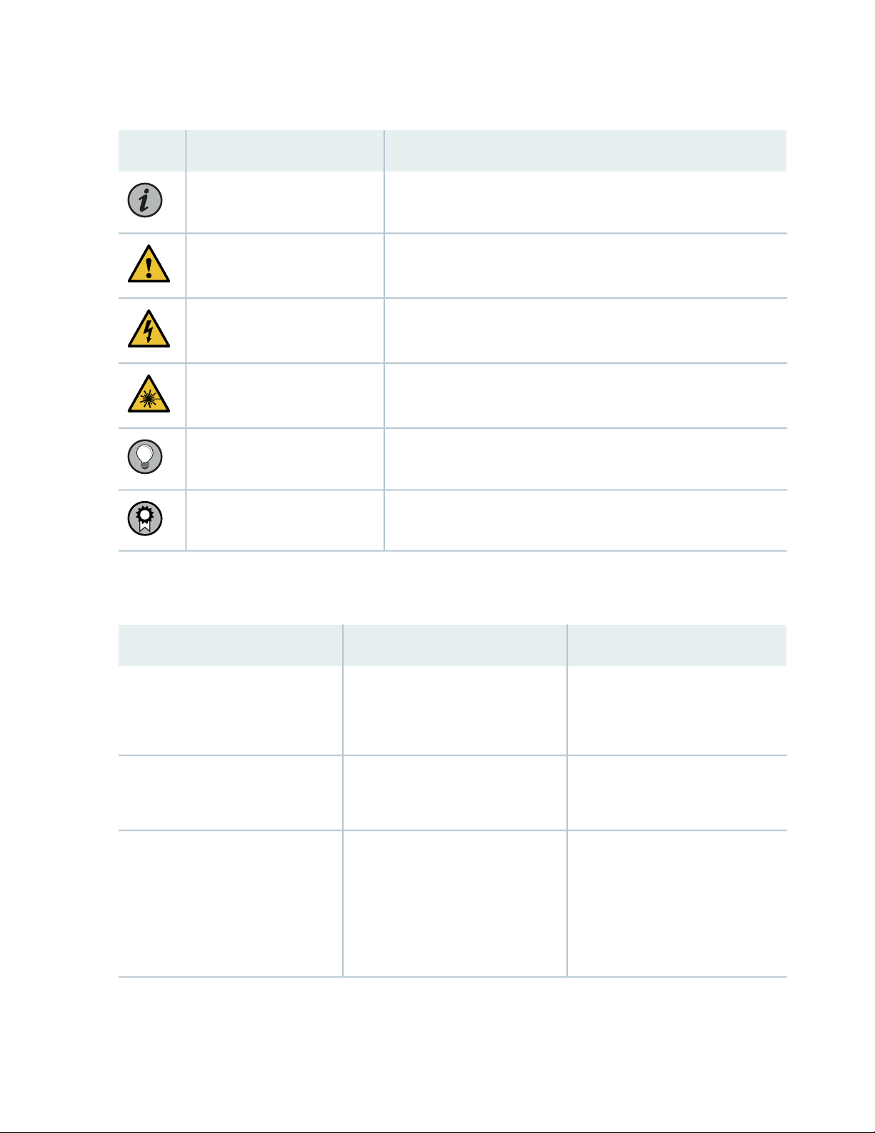
Table 1: Notice Icons
xiv
DescriptionMeaningIcon
Indicates important features or instructions.Informational note
Caution
Indicates a situation that might result in loss of data or hardware
damage.
Alerts you to the risk of personal injury or death.Warning
Alerts you to the risk of personal injury from a laser.Laser warning
Indicates helpful information.Tip
Alerts you to a recommended use or implementation.Best practice
Table 2 on page xiv defines the text and syntax conventions used in this guide.
Table 2: Text and Syntax Conventions
ExamplesDescriptionConvention
Fixed-width text like this
Italic text like this
Represents text that you type.Bold text like this
Represents output that appears on
the terminal screen.
Introduces or emphasizes important
•
new terms.
Identifies guide names.
•
Identifies RFC and Internet draft
•
titles.
To enter configuration mode, type
the configure command:
user@host> configure
user@host> show chassis alarms
No alarms currently active
A policy term is a named structure
•
that defines match conditions and
actions.
Junos OS CLI User Guide
•
RFC 1997, BGP Communities
•
Attribute
Page 15

Table 2: Text and Syntax Conventions (continued)
xv
ExamplesDescriptionConvention
Italic text like this
Text like this
< > (angle brackets)
| (pipe symbol)
Represents variables (options for
which you substitute a value) in
commands or configuration
statements.
Represents names of configuration
statements, commands, files, and
directories; configuration hierarchy
levels; or labels on routing platform
components.
variables.
Indicates a choice between the
mutually exclusive keywords or
variables on either side of the symbol.
The set of choices is often enclosed
in parentheses for clarity.
Configure the machine’s domain
name:
[edit]
root@# set system domain-name
domain-name
To configure a stub area, include
•
the stub statement at the [edit
protocols ospf area area-id]
hierarchy level.
The console port is labeled
•
CONSOLE.
stub <default-metric metric>;Encloses optional keywords or
broadcast | multicast
(string1 | string2 | string3)
# (pound sign)
[ ] (square brackets)
Indention and braces ( { } )
; (semicolon)
GUI Conventions
Indicates a comment specified on the
same line as the configuration
statement to which it applies.
Encloses a variable for which you can
substitute one or more values.
Identifies a level in the configuration
hierarchy.
Identifies a leaf statement at a
configuration hierarchy level.
rsvp { # Required for dynamic MPLS
only
community name members [
community-ids ]
[edit]
routing-options {
static {
route default {
nexthop address;
retain;
}
}
}
Page 16
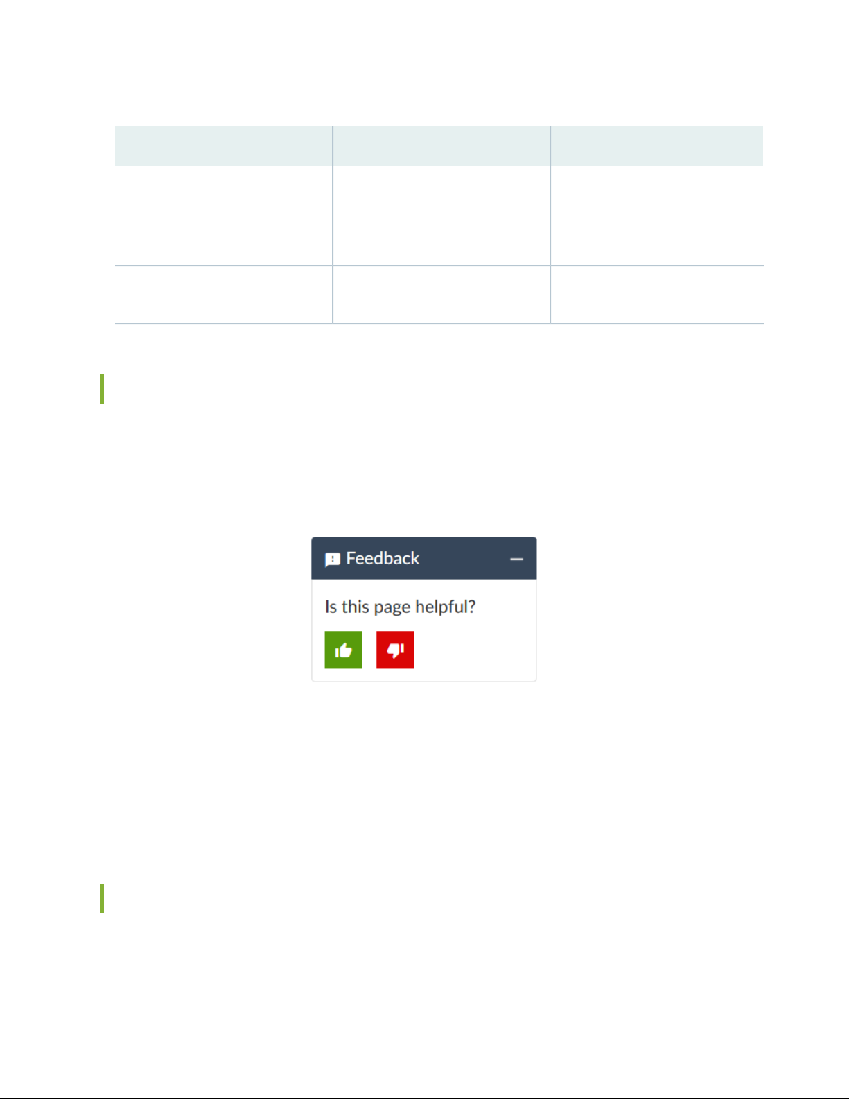
Table 2: Text and Syntax Conventions (continued)
xvi
ExamplesDescriptionConvention
Bold text like this
> (bold right angle bracket)
Represents graphical user interface
(GUI) items you click or select.
Separates levels in a hierarchy of
menu selections.
In the Logical Interfaces box, select
•
All Interfaces.
To cancel the configuration, click
•
Cancel.
In the configuration editor hierarchy,
select Protocols>Ospf.
Documentation Feedback
We encourage you to provide feedback so that we can improve our documentation. You can use either
of the following methods:
Online feedback system—Click TechLibrary Feedback, on the lower right of any page on the Juniper
•
Networks TechLibrary site, and do one of the following:
Click the thumbs-up icon if the information on the page was helpful to you.
•
Click the thumbs-down icon if the information on the page was not helpful to you or if you have
•
suggestions for improvement, and use the pop-up form to provide feedback.
E-mail—Send your comments to techpubs-comments@juniper.net. Include the document or topic name,
•
URL or page number, and software version (if applicable).
Requesting Technical Support
Technical product support is available through the Juniper Networks Technical Assistance Center (JTAC).
If you are a customer with an active Juniper Care or Partner Support Services support contract, or are
Page 17

covered under warranty, and need post-sales technical support, you can access our tools and resources
online or open a case with JTAC.
JTAC policies—For a complete understanding of our JTAC procedures and policies, review the JTAC User
•
Guide located at https://www.juniper.net/us/en/local/pdf/resource-guides/7100059-en.pdf.
Product warranties—For product warranty information, visit https://www.juniper.net/support/warranty/.
•
JTAC hours of operation—The JTAC centers have resources available 24 hours a day, 7 days a week,
•
365 days a year.
Self-Help Online Tools and Resources
For quick and easy problem resolution, Juniper Networks has designed an online self-service portal called
the Customer Support Center (CSC) that provides you with the following features:
Find CSC offerings: https://www.juniper.net/customers/support/
•
Search for known bugs: https://prsearch.juniper.net/
•
xvii
Find product documentation: https://www.juniper.net/documentation/
•
Find solutions and answer questions using our Knowledge Base: https://kb.juniper.net/
•
Download the latest versions of software and review release notes:
•
https://www.juniper.net/customers/csc/software/
Search technical bulletins for relevant hardware and software notifications:
•
https://kb.juniper.net/InfoCenter/
Join and participate in the Juniper Networks Community Forum:
•
https://www.juniper.net/company/communities/
Create a service request online: https://myjuniper.juniper.net
•
To verify service entitlement by product serial number, use our Serial Number Entitlement (SNE) Tool:
https://entitlementsearch.juniper.net/entitlementsearch/
Creating a Service Request with JTAC
You can create a service request with JTAC on the Web or by telephone.
Visit https://myjuniper.juniper.net.
•
Call 1-888-314-JTAC (1-888-314-5822 toll-free in the USA, Canada, and Mexico).
•
For international or direct-dial options in countries without toll-free numbers, see
https://support.juniper.net/support/requesting-support/.
Page 18

1
CHAPTER
Overview
MX10016 System Overview | 21
MX10016 Chassis | 35
MX10016 Cooling System | 44
MX10016 Power System | 57
MX10016 Routing and Control Board | 75
MX10016 Switch Fabric Board | 80
Line card (MX10K-LC2101) | 84
Page 19

Page 20
MX10016 System Overview
IN THIS SECTION
MX10016 Hardware Overview | 21
MX10016 Components and Configurations | 31
MX10016 Component Redundancy | 33
MX10016 Hardware and CLI Terminology Mapping | 33
The MX10000 line of 5G Universal Routing Platforms—including the MX10008 and MX10016 give cloud
and service providers the performance and scalability needed to outpace increased traffic demands.
MX10016 router provides 10-Gigabit Ethernet, 40-Gigabit Ethernet, and 100-Gigabit Ethernet modular
solutions that support up to 2.4 Tbps per slot. The MX10016 router provides redundancy and resiliency.
All major hardware components including the power system, the cooling system, the control board and
the switch fabrics are fully redundant.
21
MX10016 Hardware Overview
IN THIS SECTION
Benefits of the MX10016 Router | 22
Chassis Description | 23
Routing and Control Board | 25
Line Card (MX10K-LC2101) | 26
Switch Fabric Boards | 26
Cooling System | 27
Power Supplies | 28
Software on MX10016 | 31
Juniper Networks MX10016 Universal Routing Platform enables cloud and data center operators to
transition from 10-Gigabit Ethernet and 40-Gigabit Ethernet networks to 100-Gigabit Ethernet
Page 21

high-performance networks. The 21 rack unit (21 U) modular chassis can provide 38.4 Tbps of throughput.
The MX10016 router has 16 slots for the line cards that can support a maximum of 1536 10-Gigabit
Ethernet ports, 384 40-Gigabit Ethernet ports, or 384 100-Gigabit Ethernet ports.
The MX10016 universal router provides 2.4 Tbps per slot fabric capacity for the service providers and
cloud operators. You can deploy the MX10016 router in an IP edge network using an MX10K-LC2101
line card (ordering model number is JNP10K-LC2101).
You can deploy MX10016 in the edge of the network for the following functions:
Layer 3 peering
•
Data center gateway
•
VPLS aggregation
•
Layer 3 aggregation
•
Video distribution
•
The MX10016 router is available in both base and redundant configurations for both AC and DC operation.
MX10016 features front-to-back airflow (also known as airflow out or AFO).
22
Benefits of the MX10016 Router
System capacity— MX10016 scales to 38.4 Tbps (76.8 Tbps half- duplex) in a single chassis, with support
•
for up to 1536 10-Gigabit Ethernet, 384 40-Gigabit Ethernet, and 384 100-Gigabit Ethernet interfaces.
Full-scale IP and MPLS routing—The MX10016 delivers a distributed peering scale of 8.6 million entries
•
in the forwarding information bases (FIBs, also known as forwarding tables) and 80 million entries in the
routing information bases (RIBs also known as routing tables).
Source Packet Routing in Networking (SPRING)—SPRING on the MX10016 provides additional flexibility
•
per packet source. SPRING provides features such as network path and node protection to support
MPLS fast reroute (FRR) mechanisms, enhanced network programmability, OAM functionality, simplified
network signaling, load balancing, and traffic engineering functions.
Always-on infrastructure base—The MX10016 is engineered with full hardware redundancy for cooling,
•
switch fabric, and host subsystems—Routing and Control Boards (RCBs)—allowing service providers to
meet stringent service-level agreements across the core.
Nondisruptive software upgrades—The Junos operating system on MX10016 supports high availability
•
(HA) features such as graceful Routing Engine switchover (GRES), nonstop active routing (NSR), and
unified in-service software upgrade (unified ISSU), providing software upgrades and changes without
disrupting network traffic.
Page 22
Chassis Description
g100420
1
2
3
5
4
4
4
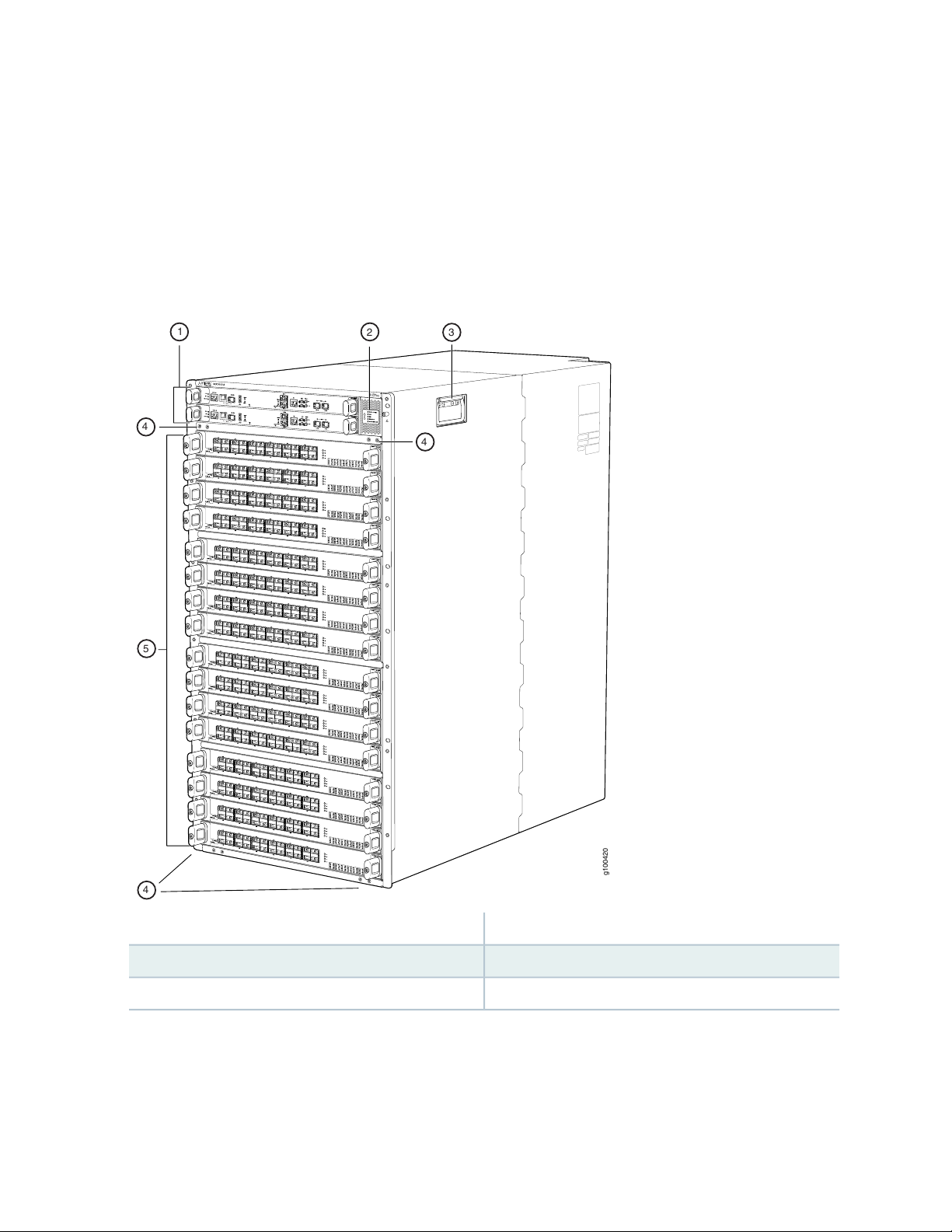
The MX10016 is 21 U tall. Two MX10016 chassis can fit in a standard 42 U rack when there is adequate
cooling and power. All key MX10016 components are field-replaceable units (FRUs).
Figure 1 on page 23 illustrates the components visible from the front of the chassis.
Figure 1: MX10016 Chassis Front
23
4—1— Installation holes for the front panelRouting and Control Boards
5—2— Line card slots 0-15 (numbered top to bottom)Status LED panel
3—Handle
Some chassis ship with an enhanced power bus to support the power needs of higher wattage line cards.
Chassis with the enhanced power bus have a modified Status Panel (see “MX10016 Status Panel LEDs”
on page 39).
Page 23
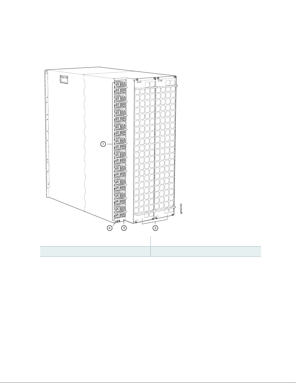
Figure 2 on page 24 illustrates the components that are visible from the rear of the chassis.
Figure 2: MX10016 Chassis Rear
24
3—1— ESD pointAC or DC power supplies
4—2— Protective earthing terminalFan trays with redundant fans
Figure 3 on page 25 illustrates the components that are internal to the chassis.
Page 24
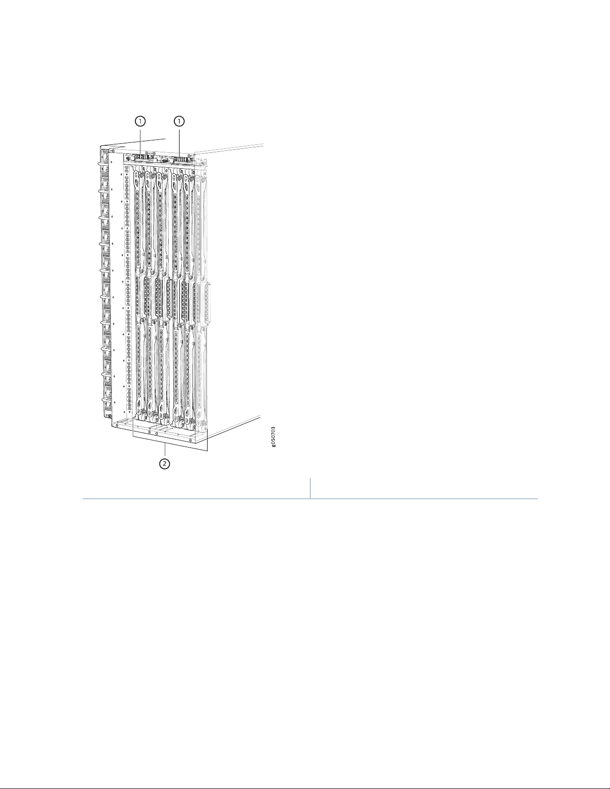
Figure 3: MX10016 Chassis Internal Components
25
2—1— Switch Fabric Boards (SFBs)Fan tray controllers
See “MX10016 Chassis Physical Specifications” on page 35.
Routing and Control Board
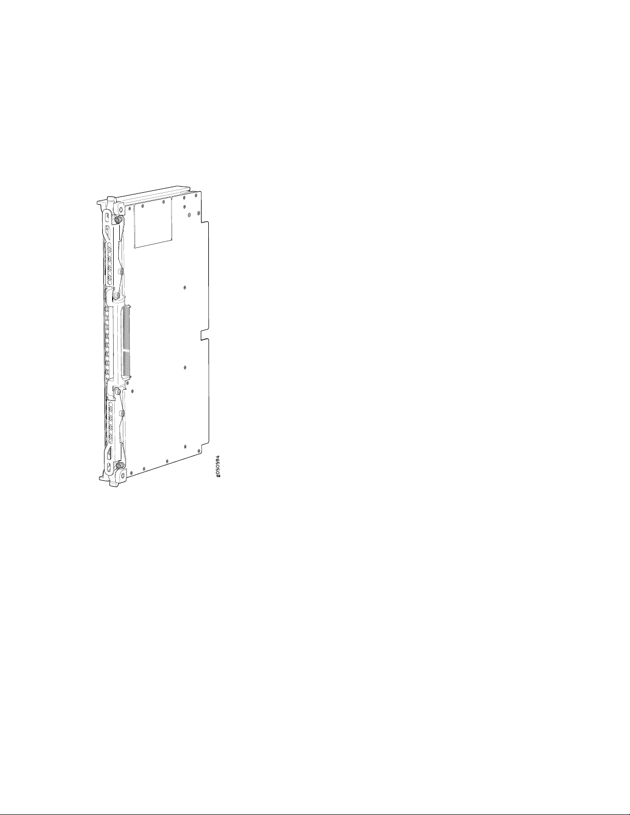
The Routing and Control Board (RCB) (see Figure 4 on page 26) contains a Routing Engine and is responsible
for the system management and control in the MX10016. See “MX10016 Routing and Control Board” on
page 75. RCBs are FRUs that are installed in the front of the chassis in the slots labeled CB0 and CB1. The
base configuration has a single RCB while the fully redundant configuration has two RCBs. The RCB also
contains Precision Time Protocol ports and two Media Access Control Security (MACsec) capable ports
(see “MX10016 Components and Configurations” on page 31).
Page 25
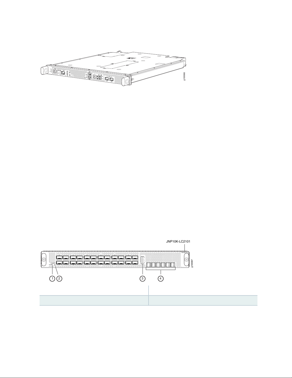
Figure 4: MX10016 Routing and Control Board
g100066
g100087
JNP10K-LC2101
1 2 3 4
Line Card (MX10K-LC2101)
The MX10016 has 16 horizontal line card slots and supports line rates for each line card. The line cards
include a Packet Forwarding Engine and Ethernet interfaces enclosed in a single assembly. The MX10016
line card architecture is based on a number of identical, independent Packet Forwarding Engine slices,
each with 400 Gbps full-duplex throughput. Line cards are FRUs that can be installed in the line card slots
labeled 0 through 15 (top to bottom) on the front of the chassis. All line cards are hot-removable and
hot-insertable. After the hot insertion, the line card comes online automatically.
26
The MX10K-LC2101 line card is available for the MX10016. The MX10K-LC2101 line card can support
24 100-Gigabit Ethernet ports with a 28-Gbps quad smallform-factor pluggable (QSFP28) transceiver, or
24 40-Gigabit Ethernet ports with a QSFP transceiver. The MX10K-LC2101 line cards also support
10-Gigabit Ethernet interfaces. For 10-Gigabit Ethernet, you must configure the port using the channelization
command. Because there is no port-groups option for the 100-Gigabit Ethernet line card, you must use
individual port channelization commands.
Figure 5 on page 26 shows the MX10K-LC2101 line card.
Figure 5: MX10K-LC2101 Line Card
3—1— Lane LEDsOFFLINE button
4—2— Port LEDsOK/FAIL LED
Switch Fabric Boards
Five Switch Fabric Boards (SFBs) provide the necessary switching functionality to an MX10016 router. A
sixth SFB is available in the redundant configuration to provide n+1 redundancy. SFBs are installed between
Page 26
the line cards and the fan trays inside the chassis (see Figure 6 on page 27). Each MX10016 SFB has sixteen
connectors that match to a line card slot, eliminating the need for a backplane. When all the SFBs are
installed, the MX10016 router has a net switching capacity of 2.4 terabytes per second (bidirectional). See
“MX10016 Switch Fabric Board” on page 80.
Figure 6: MX10016 SFB
27
Cooling System
The cooling system in the MX10016 consists of two hot-removable and hot-insertable FRU fan trays (see
Figure 7 on page 28) and two fan tray controllers (see Figure 8 on page 28).
Two fan tray models and their associated fan tray controllers are available. Both models of fan tray contain
11 fans. The fan trays install vertically on the rear of the chassis and provide front to back chassis cooling.
For model differences, see “MX10016 Cooling System and Airflow” on page 45.
Page 27
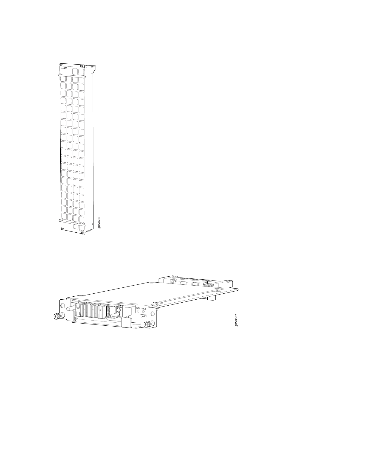
Figure 7: Fan Tray JNP10008-FAN
28
Figure 8: Fan Tray Controller JNP10008-FAN-CTRL
Power Supplies
Power supplies for the MX10016 router are fully redundant, load-sharing, and hot-removable and
hot-insertable FRUs. Each MX10016 router with a base configuration has five power supplies; redundant
configurations hold a maximum of ten AC or DC power supplies. Each power supply has an internal fan
for cooling. See Figure 9 on page 29 through Figure 12 on page 30.
Page 28
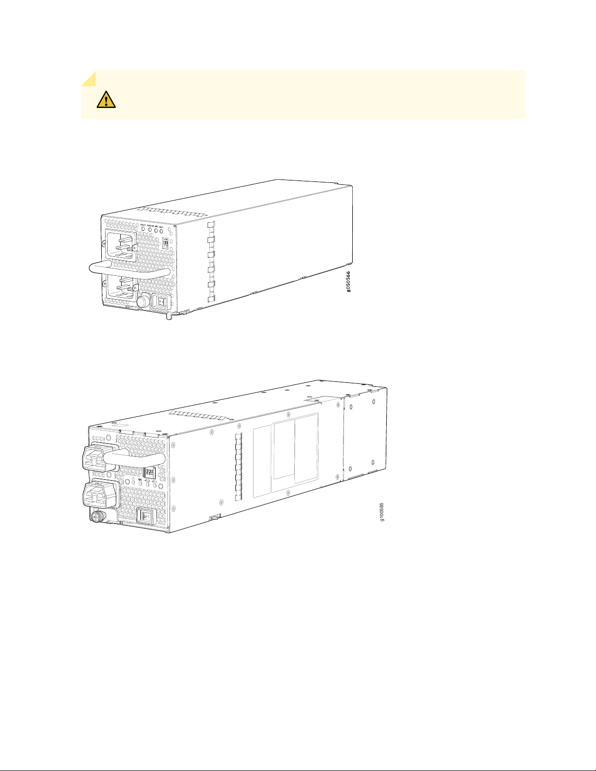
CAUTION: Do not mix AC and DC power supplies in the same chassis.
g100585
Figure 9: JNP10K-PWR-AC Power Supply
29
Figure 10: JNP10K-PWR-AC2 Power Supply
Page 29
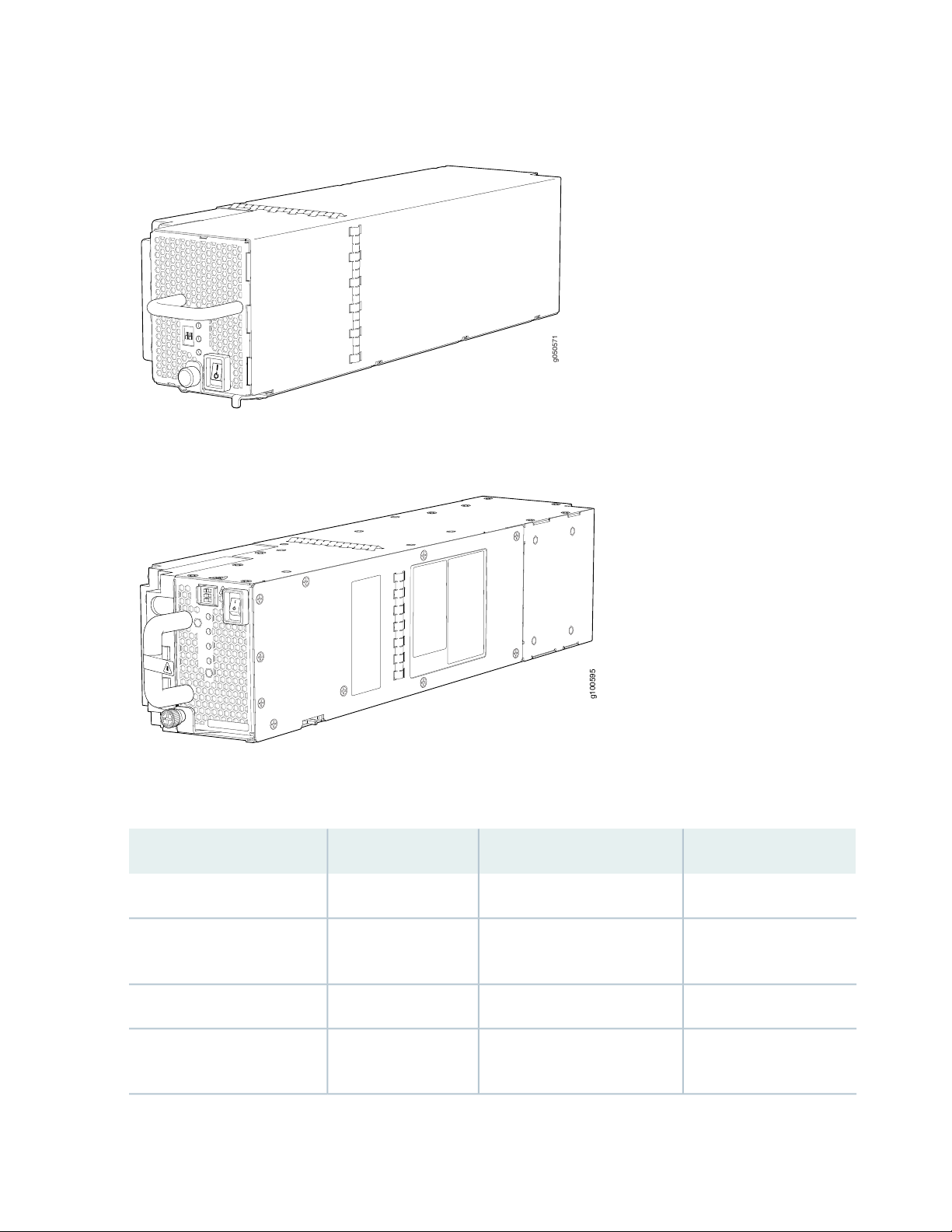
Figure 11: JNP10K-PWR-DC Power Supply
g050571
g100595
Figure 12: JNP10K-PWR-DC2 Power Supply
30
Table 3 on page 30 provides an overview of the differences among the power supplies.
Table 3: Power Supply Overview
Power BusWattageInput TypePower Supply Model
Standard or enhanced2700 WAC onlyJNP10K-PWR AC
AC, HVAC, or HVDCJNP10K-PWR-AC2
dual feed
DC onlyJNP10K-PWR-DC2
dual feed
Enhanced5000 W, single feed; 5500 W,
Standard or enhanced2500 WDC onlyJNP10K-PWR DC
Enhanced2750 W, single feed; 5500 W,
Page 30

Software on MX10016
The MX10016 router runs Junos OS, which provides Layer 3 routing services. The same Junos OS code
base that runs on the MX10016 router also runs on all Juniper Networks M Series, MX Series, and T Series
routers and SRX Series Services Gateways.
MX10016 Components and Configurations
Table 4 on page 31 lists the four hardware configurations for an MX10016 modular chassis—base (AC
version), and redundant (AC and DC versions)—and the components included in each configuration.
Table 4: MX10016 Hardware Configurations
Configuration ComponentsRouter Configuration
31
Base AC configuration
MX10016-BASE
Base DC configuration
MX10016-BASE
Chassis, including power bus
•
One Routing and Control Board
•
One control board cover panel
•
Two fan tray controllers
•
Two fan trays
•
Five 2700 W AC power supplies
•
Five power supply cover panels
•
Five Switch Fabric Boards (SFBs)
•
One SFB cover panel
•
Sixteen line card cover panels
•
Chassis, including power bus
•
One Routing and Control Board
•
One control board cover panel
•
Two fan tray controllers
•
Two fan trays
•
Five 2500 W DC power supplies
•
Five power supply cover panels
•
Five Switch Fabric Boards (SFBs)
•
One SFB cover panel
•
Sixteen line card cover panels
•
Page 31

Table 4: MX10016 Hardware Configurations (continued)
Configuration ComponentsRouter Configuration
32
Redundant AC configuration
MX10016-PREMIUM
Redundant DC configuration
MX10016-PREMIUM
Chassis, including power bus
•
Two Routing and Control Boards
•
Two fan tray controllers
•
Two fan trays
•
Ten 2700 W AC power supplies
•
Six SFBs
•
Sixteen line card cover panels
•
Chassis, including power bus
•
Two Routing and Control Boards
•
Two fan tray controllers
•
Two fan trays
•
Ten 2500 W DC power supplies
•
Six SFBs
•
Sixteen line card cover panels
•
NOTE: You can install up to sixteen line cards in the router.
NOTE: Line cards and the cable management system are not part of the base or redundant
configurations. You must order them separately.
NOTE: If you want to purchase additional power supplies (AC or DC), SFBs, or RCBs for your router
configuration, you must order them separately.
Page 32

MX10016 Component Redundancy
The MX10016 router is designed so that no single point of failure can cause the entire system to fail. The
following major hardware components in the redundant configuration provide redundancy:
Routing and Control Board (RCB)—The RCB consolidates the Routing Engine function with the control
•
plane function in a single unit. The MX10016 router can have one RCB in a base configuration or two
RCBs in a redundant configuration. When two RCBs are installed, one functions as the master and the
other functions as the backup. If the master RCB (or either of its components) fails, the backup can take
over as the master. See “MX10016 Routing and Control Board” on page 75.
Switch Fabric Boards (SFBs)—The MX10016 router has six SFB slots. Five SFBs are required for base
•
operation and the sixth SFB provides n+1 redundancy. All six SFBs are active and can sustain full
throughput rate. The fabric plane can tolerate one SFB failure without any loss of performance. See
“MX10016 Switch Fabric Board” on page 80.
Power supplies—The MX10016 router requires three power supplies for minimum operation. Additional
•
power supplies, provide n+1 redundancy for the system. AC, DC, HVAC, and HVDC systems tolerate a
single power supply to fail without system interruption. If one power supply fails in a fully redundant
system, the other power supplies can provide full power to the MX10016 router indefinitely.
33
The MX10016 router also supports source redundancy. Two sets of lugs are provided for the
JNP10K-PWR-AC cables, four sets of lugs are provided for the JNP10K-PWR-DC2 cables, and two AC
power cords are provided for each JNP10K-PWR-AC2 power supply.
Cooling system—The fan trays have redundant fans, which are controlled by the fan tray controller. If
•
one of the fans fails, the host subsystem increases the speed of the remaining fans to provide sufficient
cooling for the router indefinitely. See “MX10016 Cooling System” on page 44.
MX10016 Hardware and CLI Terminology Mapping
This topic describes the hardware terms used in MX10016 router documentation and the corresponding
terms used in the Junos OS CLI. See Table 5 on page 33.
Table 5: CLI Equivalents of Terms Used in Documentation for MX10016 Routers
Hardware
Item (CLI)
Chassis
[MX10016]
Item in
DocumentationValue (CLI)Description (CLI)
Router chassis–JNP10016
Additional Information
“MX10016 Chassis
Physical Specifications”
on page 35
Page 33

Table 5: CLI Equivalents of Terms Used in Documentation for MX10016 Routers (continued)
34
Hardware
Item (CLI)
Control
Board
FPC (n)
Xcvr (n)
CB (n)Routing and
Abbreviated name
of the Flexible PIC
Concentrator
(FPC)
On MX10016, an
FPC equates to a
line card.
Abbreviated name
of the transceiver
n is a value in the range
of 0–1.
Multiple line items appear
in the CLI if more than
one RCB is installed in
the chassis.
n is a value in the range
of 0–15. The value
corresponds to the line
card slot number in which
the line card is installed.
the number of the port in
which the transceiver is
installed.
Item in
DocumentationValue (CLI)Description (CLI)
Line card (The router
does not have actual
FPCs—the line cards are
the FPC equivalents on
the router.)
Optical transceiversn is a value equivalent to
Additional Information
“MX10016 Routing and
Control Board” on
page 75
Understanding Interface
Naming Conventions
“MX10016 Transceiver
and Cable Specifications”
on page 115
PSU (n)
Fan tray
One of the
following:
JNP10K-PWR-AC
•
JNP10K-PWR-AC2
•
JNP10K-PWR-DC
•
JNP10K-PWR-DC2
•
JNP10016-FAN2
of 0–9. The value
corresponds to the power
supply slot number.
AC or DC power supplyn is a value in the range
One of the following:
JNP10K-PWR-AC
•
Power Supply on
page 58
•
JNP10K-PWR-DC
•
Power Supply on
page 62
•
Fan tray–JNP10016-FAN or
“MX10016 Cooling
System” on page 44
Page 34

Table 5: CLI Equivalents of Terms Used in Documentation for MX10016 Routers (continued)
35
Hardware
Item (CLI)
SFB (n)
This field indicates:
State of the
•
fabric plane:
Active
•
Spare
•
Check State
•
Status of the
•
Packet
Forwarding
Engine in each
fabric plane:
Links OK
•
Error
•
of 0–5.
Item in
DocumentationValue (CLI)Description (CLI)
Additional Information
show chassis sfbFabric planen is a value in the range
MX10016 Chassis
IN THIS SECTION
MX10016 Chassis Physical Specifications | 35
MX10016 Field-Replaceable Units | 38
MX10016 Status Panel LEDs | 39
MX10016 Optional Equipment | 42
MX10016 Chassis Physical Specifications
The MX10016 modular chassis is a rigid sheet-metal structure that houses the field-replaceable units
(FRUs). You can mount up to two MX10016 chassis in a standard 19-in. four-post (42 U) rack, provided
the rack can handle the combined weight and there is adequate power and cooling.Table 6 on page 36
summarizes the physical specifications of the chassis. See Figure 13 on page 37.
Page 35

Table 6: MX10016 Chassis Physical Specifications
36
DepthWidthHeightWeightDescription
Chassis, spare
Chassis base AC configuration
Includes 1 Control Board, 5 AC
power supplies, 2 fan trays, 2 fan
tray controllers, and 5 Switch
Ffabric Boards (SFBs)
Chassis redundant AC
configuration
Includes 2 Control Boards, 10 AC
power supplies, 2 fan trays, 2 fan
tray controllers, and 6 SIBs
Chassis base DC configuration
Includes 1 Control Board, 5 DC
power supplies, 2 fan trays, 2 fan
tray controllers, and 5 SIBs
220 lb
(99.79 kg)
522 lb
(236.78 kg)
596 lb
(270.34 kg)
519.5 lb
(235.65 kg)
36.6 in.
(92.96 cm)
36.6 in.
(92.96 cm)
36.6 in.
(92.96 cm)
36.6 in.
(92.96 cm)
17.4 in. (44.2 cm)
NOTE: The outer edges of the
mounting-bracket flange extend
the width to 19 in. (48.3 cm).
17.4 in. (44.2 cm)
NOTE: The outer edges of the
mounting-bracket flange extend
the width to 19 in. (48.3 cm).
17.4 in. (44.2 cm)
NOTE: The outer edges of the
mounting-bracket flange extend
the width to 19 in. (48.3 cm).
17.4 in. (44.2 cm)
NOTE: The outer edges of the
mounting-bracket flange extend
the width to 19 in. (48.3 cm).
35 in.
(88.9 cm)
35 in.
(88.9 cm)
35 in.
(88.9 cm)
35 in.
(88.9 cm)
Chassis redundant DC
configuration
Includes 2 Control Boards, 10 DC
power supplies, 2 fan trays, 2 fan
tray controllers, and 6 SIBs
591 lb
(268.07 kg)
36.6 in.
(92.96 cm)
17.4 in. (44.2 cm)
NOTE: The outer edges of the
mounting-bracket flange extend
the width to 19 in. (48.3 cm).
35 in.
(88.9 cm)
Page 36

Figure 13: Front View of an MX10016
g100420
1
2
3
5
4
4
4
37
4—1— Mounting holes for front panelRouting and Control Boards
5—2— Line cardsStatus panel
3—Handles
WARNING: The handles on each side of the chassis facilitate the fine-tune positioning
of the chassis on the mounting brackets. Do not use the handles to lift the chassis, even
when the chassis is empty. See “Installing an MX10016 into a Four-Post Rack” on page 139
for instructions for properly moving a loaded chassis.
Page 37

MX10016 Field-Replaceable Units
Field-replaceable units (FRUs) are router components that you can replace at your site. The router uses
these types of FRUs:
Hot-insertable and hot-removable—You can remove and replace these components without powering
•
off the router or disrupting the routing function.
Hot-pluggable—You can remove and replace these components without powering off the router, but
•
the routing function is interrupted until you replace the component.
Table 7 on page 38 lists the FRUs and their types for the MX10016 routers.
Table 7: Field-Replaceable Units in an MX10016 Router
TypeFRU
Hot-insertable and hot-removable.Power supplies
38
Routing and Control Board (RCB)
Switch Fabric Boards (SFBs)
Hot-insertable and hot-removable.Fan tray
Hot-insertable and hot-removable.Fan tray controller
Redundant configuration:
Master RCB is hot-pluggable.
•
Backup RCB is hot-insertable and hot-removable.
•
Base configuration:
Removing the RCB causes the router to shut down. You can install a replacement
•
Control Board in the second slot. The system restarts to elect a master and
backup. If necessary, you can switch the master and backup using the request
chassis routing-engine master switch command. We recommend that you take
the backup RCB offline before removing it.
See “MX10016 Components and Configurations” on page 31.
SFBs are hot-insertable and hot-removable. We recommend that you take SFBs
offline before removing them to avoid traffic loss while the router fabric is being
reconfigured. Use the following command:
Line cards
user@router> request chassis sib (offline | online) slot slot-number offline
Hot-insertable and hot-removable. We recommend that you take line cards offline
before removing them. For example:
user@router> request chassis fpc slot slot-number offline
Page 38

Table 7: Field-Replaceable Units in an MX10016 Router (continued)
TypeFRU
Hot-insertable and hot-removable.Optical transceivers
NOTE: Line cards are not part of the base or redundant configuration. You must order them
separately.
NOTE: If you have a Juniper Care service contract, register any addition, change, or upgrade of
hardware components at https://www.juniper.net/customers/support/tools/updateinstallbase/.
Failure to do so can result in significant delays if you need replacement parts. This note does not
apply if you replace an existing component with the same type of component.
39
SEE ALSO
MX10016 Components and Configurations | 31
MX10016 Status Panel LEDs
The status panel of the MX10016 routers has two purposes:
Shows the overall status of the chassis
•
Indicates the type of power bus internal to the chassis
•
Starting in May 2019, new chassis ship with an enhanced power bus to support the power needs of higher
wattage line cards.
The status panel of the MX10016 shows the overall status of the chassis through a set of five bi-color
LEDs (see Figure 14 on page 40 for a chassis with the original power bus).
Page 39

Figure 14: MX10016 Status Panel
g100339
Chassis that are shipped after May 2019 have the same set of five bi-color LEDs, but also have an azure
blue line to indicate the enhanced power bus (see Figure 15 on page 40).
Figure 15: Status Panel on Chassis with the Enhanced Power Bus
40
Table 8 on page 40 describes the status panel LEDs.
Table 8: Status Panel LEDs in an MX10016 Router
On steadilyGreenPower supplies
On steadilyYellow
OffNone
DescriptionStateColorName
All of the power supplies are online and
operating normally.
One or more of the power supplies have
an error.
None of the power supplies is receiving
power.
Page 40

Table 8: Status Panel LEDs in an MX10016 Router (continued)
41
DescriptionStateColorName
On steadilyGreenFans
On steadilyYellow
OffNone
On steadilyGreenSFBs
BlinkingYellow
BlinkingYellow
The fans and the fan tray controllers are
online and operating normally.
There is an error in a fan or in one of the
fan tray controllers.
The fan tray controllers and fan trays are
not receiving power.
All installed Switch Fabric Boards (SFBs)
are online.
There is a hardware error in one or more
SFBs.
All the SFBs are offline.OffNone
All the line cards are online.On steadilyGreenLine cards
There is a hardware error in one or more
line cards.
All the line cards are offline.OffNone
All the RCBs are online.On steadilyGreenRouting and Control Boards
BlinkingYellow
OffNone
One or more Routing and Control Boards
have an error condition.
All the installed Routing and Control
Boards are offline.
Page 41

Table 8: Status Panel LEDs in an MX10016 Router (continued)
42
DescriptionStateColorName
On steadilyRedAlarms
On steadilyYellow
Major (red)—Indicates a critical situation
on the device that has resulted from one
of the following conditions.
One or more hardware components
•
have failed.
One or more hardware components
•
have exceeded temperature thresholds.
An alarm condition configured on an
•
interface has triggered a critical warning.
A red alarm condition requires immediate
action.
Minor (yellow or amber)—Indicates a
noncritical condition on the device that, if
left unnoticed, might cause an interruption
in service or degradation in performance.
A yellow alarm condition requires
monitoring or maintenance. For example,
a missing rescue configuration generates
a yellow system alarm.
MX10016 Optional Equipment
The MX10016 router supports the cable management system as an optional piece of equipment.
The cable management system (see Figure 16 on page 43) enables you to route optical cables away from
the line card ports for better airflow through the chassis. Using this optional system also makes it easier
to use cable ties or strips to organize the cabling.
Page 42

Figure 16: MX10016 Cable Management System
g100214
The cable management system is comprises a set of handle extensions and a tray that snaps to the
extensions (see Figure 17 on page 43) for an individual line card. The handle extensions can be used with
or without the cable tray. It is not necessary to remove the handle extensions if you want to remove a line
card.
43
Figure 17: MX10016 Cable Management Parts
2—1— Cable trayHandle extensions
Cables are draped across or under the handle extensions and then secured with cable wraps (see
Figure 18 on page 44).
Page 43

Figure 18: Two Cable Management Systems Installed on an MX10016
g100215
44
RELATED DOCUMENTATION
MX10016 Routing and Control Board | 75
MX10016 Switch Fabric Board | 80
MX10016 Power System | 57
MX10016 Cooling System
IN THIS SECTION
MX10016 Cooling System and Airflow | 45
MX10016 Fan Tray LEDs and Fan Tray Controller LEDs | 50
Page 44

The MX10016 cooling system components work together to keep all components within the acceptable
temperature range. If the maximum temperature specification is exceeded and the system cannot be
adequately cooled, the Routing and Control Board shuts down some or all of the hardware components.
For more information, see the following topics:
MX10016 Cooling System and Airflow
IN THIS SECTION
MX10016 Fan Trays | 46
MX10016 Fan Tray Controllers | 47
Airflow Direction in an MX10016 | 49
45
The cooling system in an MX10016 chassis consists of two fan trays and two fan tray controllers. An
MX10016 has an air filter on the front panel. The fans in each fan tray are numbered 0 through 10.
Two fan tray models and their associated fan tray controllers are available. All models are hot-insertable
and hot-removable. See Table 9 on page 45.
Table 9: Fan Tray Specifications
JNP10016-FAN2JNP10016-FANSpecification
JNP10016-FTC2JNP10016-FAN-CTLRCorresponding fan tray controller
model
Enhanced or standardEnhanced or standardChassis supported
2211Number of fans per fan tray
4422Number of fans per chassis
3,423 CFM per fan tray2,744.07 CFM per fan trayVolume flow at 100%
19.2R115.1X53-D30Introduced in Junos OS Release
22.4 in. (56.9 cm)22.4 in. (56.9 cm)Height
6.6 in. (16.8 cm)6.6 in. (16.8 cm)Width
Page 45

Table 9: Fan Tray Specifications (continued)
46
JNP10016-FAN2JNP10016-FANSpecification
Depth
4.0 in. (10.2 cm) without handles,
5.2 in. (13.2 cm) with handles
5.5 in. (13.97 cm) without handles,
6.7 in. (17.01 cm with handles)
33.8lb (15.33 kg)19.8 lb (8.98 kg)Weight
The JNP10016-FAN2 and JNP10016-FAN2-CTRL are optimized to work best in the enhanced chassis,
but are backwards compatible to work in the standard chassis. To determine which chassis you have, see
“MX10016 Status Panel LEDs” on page 39.
MX10016 Fan Trays
Each fan tray is a hot-insertable and hot-removable FRU. Each fan tray contains 21 fans (0-20), a
non-removable Control Board, and LEDs.
The two fan trays install vertically, side by side, next to the power supplies on the rear side of the chassis.
Two handles on each front faceplate facilitate handling of the fan tray. See Figure 19 on page 46.
Figure 19: MX10016 Fan Tray
Page 46

If you want to replace an existing fan tray while the router is running, remove only one fan tray. The router
continues to operate for a limited time with a single operating fan tray without triggering a thermal alarm.
CAUTION: To avoid a thermal alarm, do not remove both fan trays while the router is
operating.
CAUTION: The chassis will shut down if a thermal alarm is raised for more than 3 minutes.
The internal fan control board in each fan tray contains LEDs for the associated fan tray controllers and
LEDs for the three SFBs directly behind the fan tray.
MX10016 Fan Tray Controllers
47
Two fan tray controllers provide the control logic and power to hot-insert and hot-remove a fan tray. The
fans in each fan tray are numbered 0 through 20.
The system continually monitors the temperature of critical parts across the chassis and adjusts the chassis
fan speed according to the temperature.
Software controls the fan speed. Under normal operating conditions, the fans in the fan tray run at less
than full speed.If one fan tray controller fails or appears missing (such as when an SFB is being replaced),
the other fan tray controller sets the fans to full speed. This enables the router to continue to operate
normally as long as the remaining fans cool the chassis sufficiently. Use the show chassis fan command
to see the status of individual fans and the fan speed. For example:
user@device> show chassis fan
Item Status RPM Measurement
Fan Tray 0 Fan 0 OK 7950 Spinning at normal speed
Fan Tray 0 Fan 1 OK 7800 Spinning at normal speed
Fan Tray 0 Fan 2 OK 7800 Spinning at normal speed
Fan Tray 0 Fan 3 OK 7950 Spinning at normal speed
Fan Tray 0 Fan 4 OK 7650 Spinning at normal speed
Fan Tray 0 Fan 5 OK 7650 Spinning at normal speed
Fan Tray 0 Fan 6 OK 7650 Spinning at normal speed
Fan Tray 0 Fan 7 OK 7650 Spinning at normal speed
Fan Tray 0 Fan 8 OK 7650 Spinning at normal speed
Fan Tray 0 Fan 9 OK 7650 Spinning at normal speed
Fan Tray 0 Fan 10 OK 7650 Spinning at normal speed
Page 47

Fan Tray 0 Fan 11 OK 7650 Spinning at normal speed
Fan Tray 0 Fan 12 OK 7800 Spinning at normal speed
Fan Tray 0 Fan 13 OK 7650 Spinning at normal speed
Fan Tray 0 Fan 14 OK 7650 Spinning at normal speed
Fan Tray 0 Fan 15 OK 7650 Spinning at normal speed
Fan Tray 0 Fan 16 OK 7650 Spinning at normal speed
Fan Tray 0 Fan 17 OK 7650 Spinning at normal speed
Fan Tray 0 Fan 18 OK 7800 Spinning at normal speed
Fan Tray 0 Fan 19 OK 7650 Spinning at normal speed
Fan Tray 0 Fan 20 OK 7650 Spinning at normal speed
Fan Tray 1 Fan 0 OK 7650 Spinning at normal speed
Fan Tray 1 Fan 1 OK 7650 Spinning at normal speed
Fan Tray 1 Fan 2 OK 7650 Spinning at normal speed
Fan Tray 1 Fan 3 OK 7650 Spinning at normal speed
Fan Tray 1 Fan 4 OK 7800 Spinning at normal speed
Fan Tray 1 Fan 5 OK 7650 Spinning at normal speed
Fan Tray 1 Fan 6 OK 7800 Spinning at normal speed
Fan Tray 1 Fan 7 OK 7650 Spinning at normal speed
Fan Tray 1 Fan 8 OK 7800 Spinning at normal speed
Fan Tray 1 Fan 9 OK 7650 Spinning at normal speed
Fan Tray 1 Fan 10 OK 7650 Spinning at normal speed
Fan Tray 1 Fan 11 OK 7500 Spinning at normal speed
Fan Tray 1 Fan 12 OK 7650 Spinning at normal speed
Fan Tray 1 Fan 13 OK 7650 Spinning at normal speed
Fan Tray 1 Fan 14 OK 7650 Spinning at normal speed
Fan Tray 1 Fan 15 OK 7500 Spinning at normal speed
Fan Tray 1 Fan 16 OK 7650 Spinning at normal speed
Fan Tray 1 Fan 17 OK 7500 Spinning at normal speed
Fan Tray 1 Fan 18 OK 7500 Spinning at normal speed
Fan Tray 1 Fan 19 OK 7500 Spinning at normal speed
Fan Tray 1 Fan 20 OK 7500 Spinning at normal speed
48
Two fan tray controller models and their associated fan trays are available. All models are hot-insertable
and hot-removable. See Table 10 on page 48.
Table 10: Fan Tray Controller Specifications
JNP10016-FTC2JNP10016-FAN-CTRLSpecification
JNP10016-FAN2JNP10016-FANCorresponding fan tray model
Enhanced or standardStandardChassis supported
19.2R115.1X53-D30Introduced in Junos OS Release
Page 48

Table 10: Fan Tray Controller Specifications (continued)
JNP10016-FTC2JNP10016-FAN-CTRLSpecification
1.5 in. (3.81 cm)1.5 in. (3.81 cm)Height
6.5 in. (15.24 cm)6.5 in. (15.24 cm)Width
9.4 in. (23.88 cm)9.3 in. (23.62 cm)Depth
2.3 lb (1.04 cm)1.5 lb (0.68 kg)Weight
Airflow Direction in an MX10016
The air intake to cool the chassis is located on the port (line card) side of the chassis. Air flows into the
chassis from the ports in the Control Boards and line cards, through the Switch Fabric Boards (SFBs), and
exits from the fan trays and the power supplies. This airflow is called port-to-FRU cooling or airflow out
(AFO). See Figure 20 on page 49.
49
Figure 20: Airflow Through an MX10016
Page 49

The fan tray continues to operate indefinitely and provides sufficient cooling even when a single fan fails,
provided the room temperature is within the operating range. You can check the status of the fans by
viewing the LEDs on each fan tray. See “MX10016 Fan Tray LEDs and Fan Tray Controller LEDs” on
page 50.
You cannot replace a single fan. If one or more fans fail, you must replace the entire fan tray.
In addition to the fan trays, there is an internal fan in each power supply.
MX10016 Fan Tray LEDs and Fan Tray Controller LEDs
IN THIS SECTION
MX10016 Fan Tray LEDs | 50
MX10016 Fan Tray Controller LEDs | 55
50
Each fan tray has a set of LEDs, and each corresponding fan tray controller also has a set of LEDs. This
topic covers:
MX10016 Fan Tray LEDs
Each of the two fan trays have a set of LEDs that represent the status of the fans in the fan tray, the fan
tray controller, and the three Switch Fabric Boards (SFBs). The fan tray LEDs are located in the top-left
corner of each fan tray. Figure 21 on page 51 shows the location of the LEDs on the fan tray.
Page 50

Figure 21: Fan Tray LEDs on an MX10016
51
Fan status LED
2—Fan tray controller status
3—1— SFB status (SFB 0 through SFB 2 for the left fan tray
and SFB 3 through 5 for the right fan tray)
Table 11 on page 51 describes the functions of the fan tray LEDs.
Table 11: Fan Tray LEDs on an MX10016
On steadilyGreenFan status
BlinkingGreen
BlinkingYellow
DescriptionStateColorName
All fans are operating normally. The system
has verified that the fan tray is engaged,
that the airflow is in the correct direction,
and that all fans are operating correctly.
The beacon feature is enabled. This feature
is enabled using the request chassis
beacon command.
An error has been detected in one or more
fans in the fan tray. Replace the fan tray
as soon as possible. Either the fan has
failed or it has become disconnected. To
maintain proper airflow through the
chassis, leave the fan tray installed in the
chassis until you are ready to replace it.
OffNone
The fan is not receiving power from the
fan tray controller.
Page 51

Table 11: Fan Tray LEDs on an MX10016 (continued)
52
DescriptionStateColorName
On steadilyGreenFan tray controller status
BlinkingGreen
BlinkingYellow
OffNone
On steadilyGreenSFB 0 status
The fan tray controller is online and is
operating normally.
The beacon feature is enabled. This feature
is enabled using the request chassis
beacon command.
An error has been detected in the fan tray
controller. Replace the fan tray controller
as soon as possible. The fan tray controller
is located behind the fan tray above the
SIBs. To maintain proper airflow through
the chassis, leave the fan tray installed in
the chassis until you are ready to replace
the fan tray controller.
The fan tray controller is not receiving
power.
The leftmost SFB behind the left fan tray
is online.
BlinkingGreen
BlinkingYellow
The beacon feature is enabled. This feature
is enabled using the request chassis
beacon command.
An error has been detected in SFB 0.
Replace the SFB as soon as possible. The
SFB is located behind the left fan tray and
is the left-most SFB in the chassis. To
maintain proper airflow through the
chassis, leave the fan tray installed in the
chassis until you are ready to replace the
SFB.
The SFB is offline.OffNone
Page 52

Table 11: Fan Tray LEDs on an MX10016 (continued)
53
DescriptionStateColorName
On steadilyGreenSFB 1 status
BlinkingGreen
BlinkingYellow
On steadilyGreenSFB 2 status
The center SFB behind the left fan tray is
online.
The beacon feature is enabled. This feature
is enabled using the request chassis
beacon command.
An error has been detected in SFB 1.
Replace the SFB as soon as possible. The
SFB is located behind the left fan tray and
is the middle SFB in the grouping of 3. To
maintain proper airflow through the
chassis, leave the fan tray installed in the
chassis until you are ready to replace the
SFB.
The SFB is offline.OffNone
The rightmost SFB behind the left fan tray
is online.
BlinkingGreen
BlinkingYellow
The beacon feature is enabled. This feature
is enabled using the request chassis
beacon command.
An error has been detected in SFB 2.
Replace the SFB as soon as possible. The
SFB is located behind the left fan tray and
is the rightmost SFB in the grouping of 3.
To maintain proper airflow through the
chassis, leave the fan tray installed in the
chassis until you are ready to replace the
SFB.
The SFB is offline.OffNone
Page 53

Table 11: Fan Tray LEDs on an MX10016 (continued)
54
DescriptionStateColorName
On steadilyGreenSFB 3 status
BlinkingGreen
BlinkingYellow
On steadilyGreenSFB 4 status
The left-most SFB behind the right fan tray
is online.
The beacon feature is enabled. This feature
is enabled using the request chassis
beacon command.
An error has been detected in SFB 3.
Replace the SFB as soon as possible. The
SFB is located behind the right fan tray and
is the leftmost SFB in the grouping of 3.
To maintain proper airflow through the
chassis, leave the fan tray installed in the
chassis until you are ready to replace the
SFB.
The SFB is offline.OffNone
The center SFB behind the right fan tray
is online.
BlinkingGreen
BlinkingYellow
The beacon feature is enabled. This feature
is enabled using the request chassis
beacon command.
An error has been detected in SFB 4.
Replace the SFB as soon as possible. The
SFB is located behind the right fan tray and
is the middle SFB in the grouping of 3. To
maintain proper airflow through the
chassis, leave the fan tray installed in the
chassis until you are ready to replace the
SFB.
The SFB is offline.OffNone
Page 54

Table 11: Fan Tray LEDs on an MX10016 (continued)
55
DescriptionStateColorName
MX10016 Fan Tray Controller LEDs
On steadilyGreenSFB 5 status
BlinkingGreen
BlinkingYellow
The right-most SFB behind the right fan
tray is online.
The beacon feature is enabled. This feature
is enabled using the request chassis
beacon command.
An error has been detected in SFB 5.
Replace the SFB as soon as possible. The
SFB is located behind the right fan tray and
is the right-most SFB in the grouping of 3.
To maintain proper airflow through the
chassis, leave the fan tray installed in the
chassis until you are ready to replace the
SFB.
The SFB is offline.OffNone
The fan tray controller LEDs are only visible when the associated fan tray is removed. The fan tray controller
LEDs are located on the right of the controller panel. See Figure 22 on page 55.
Figure 22: Fan Tray Controller LEDs on an MX10016
2—1— Fan tray controller statusFan tray controller power
Table 12 on page 56 describes the functions of the fan tray controller LEDs.
Page 55

Table 12: Fan Tray Controller LEDs on an MX10016
56
DescriptionStateColorName
On steadilyGreenFan controller power
BlinkingYellow
OffNone
On steadilyGreenFan tray controller status
BlinkingGreen
The fan tray controller has power and is
operating normally.
A power error has been detected in the
fan tray controller. Replace the fan tray
controller as soon as possible. To maintain
proper airflow through the chassis, leave
the fan tray installed in the chassis until
you are ready to replace the fan tray
controller.
The fan tray controller is not powered on
or is not receiving power.
The fan tray controller is online and is
operating normally.
The beacon feature is enabled. This feature
is enabled using the request chassis
beacon command.
BlinkingYellow
OffNone
RELATED DOCUMENTATION
Removing and Installing MX10016 Cooling System Components | 162
An error has been detected in the fan tray
controller. Replace the fan tray controller
as soon as possible. To maintain proper
airflow through the chassis, leave the fan
tray installed in the chassis until you are
ready to replace the fan tray controller.
The fan tray controller is not receiving
power.
Page 56

MX10016 Power System
IN THIS SECTION
JNP10K-PWR-AC Power Supply | 58
JNP10K-PWR-AC2 Power Supply | 61
JNP10K-PWR-DC Power Supply | 62
JNP10K-PWR-DC2 Power Supply | 66
JNP10K-PWR-AC Power Supply LEDs | 68
JNP10K-PWR-AC2 Power Supply LEDs | 69
JNP10K-PWR-DC Power Supply LEDs | 71
JNP10K-PWR-DC2 Power Supply LEDs | 73
57
The MX10016 supports AC, DC, high-voltage alternating current (HVAC) and high-voltage direct current
(HVDC) by offering the following power supplies:
JNP10K-PWR-AC
•
JNP10K-PWR-AC2
•
JNP10K-PWR-DC
•
JNP10K-PWR-DC2
•
CAUTION: Do not mix AC and DC power supplies in the same chassis.
All of the power supplies are hot-insertable and hot-removable, field-replaceable units (FRUs). In the
MX10016, you can install up to 10 power supplies in the slots labeled PEM 0 through PEM 9 (top to
bottom) located in the rear of the chassis. You can install the power supplies in any slot.
The JNP10K-PWR-AC2 and JNP10K-PWR-DC2 PSMs require the enhanced power bus. To determine
whether your system has the standard power bus or the enhanced power bus, see Table 8 on page 40.
Table 13 on page 58 provides the specifications for these different power supplies.
Page 57

Table 13: Power Supply Overview
58
JNP10K-PWR-DC2JNP10K-PWR-DCJNP10K-PWR-AC2JNP10K-PWR-AC
5500 W when set for
high power (80-A) or
4400 W when set for
low power (60-A)
4 (INPUT 1, INPUT 2)2 (INPUT 1, INPUT
Standard or enhanced*StandardStandard or enhanced*StandardCompatible
output power
power bus
2700 WMaximum
when set for high power
(30-A); 3000 W when
set for low power (20-A)
2 (INP1, INP2)2 (INP1, INP2)Inputs
2500 W5000 W or 5500 W
2)
Note:
*JNP10K-PWR-AC2 and JNP10K-PWR-DC2 models can use the standard bus. The available power is 3000 W for
power budget from the power management software.
JNP10K-PWR-AC Power Supply
The JNP10K-PWR-AC power supplies are hot-insertable, hot-removable, field-replaceable units (FRUs).
In an MX10016, you can install up to 10 power supplies in the slots labeled PSU 0 through PSU 9. You
can install the power supplies in any slot.
The JNP10K-PWR-AC power supplies are 2700-W and support 200–240 VAC. The output is 12 VDC;
the output power is 2700 W.
The AC power supply supports 200–240 VAC. The output is 12 VDC; the output power is 2700 W.
CAUTION: Do not mix AC and DC power supplies in the same chassis. AC and HVAC
can coexist in the same chassis during the hot swap of AC for HVAC. Do not mix AC and
HVAC power supplies in a running environment.
WARNING: The router is pluggable type A equipment installed in a restricted-access
location. It has a separate protective earthing terminal on the chassis that must be
connected to earth ground permanently to ground the chassis adequately and protect
the operator from electrical hazards.
Page 58

CAUTION: Before you install the router, ensure that a licensed electrician has attached
an appropriate grounding lug to the grounding cable that you supply. Using a grounding
cable with an incorrectly attached lug can damage the router.
NOTE: The base configuration of MX10016 routers are shipped with five power supplies. Cover
are installed over the remaining power supply slots. You can add additional power supplies to base
configuration routers as necessary. For details about different router configurations, see “MX10016
Components and Configurations” on page 31.
Each JNP10K-PWR-AC power supply weighs approximately 6.8 lb (3.08 kg) and has two independent
16-A rated AC inlets on the faceplate. Although each inlet provides sufficient input power to provide full
output, always connect to a dedicated AC power feed to provide redundancy. Only one power feed is
operational at a time.
59
The MX10016 routers employ automatic transfer switch (ATS) technology. The MX10016 power system
provides 2nsource redundancy. If one power source fails, ATS routes the power supply to the alternate
source.
NOTE: For redundancy, always plug the two power cords from each power supply:
INP1 into an uninterruptible power supply (UPS)
•
INP2 into the public electricity supply
•
Each JNP10K-PWR-AC power supply has a power switch with international markings for on (|) and off
(O), a fan, and four LEDs on the faceplate that indicate the status of the power supply. See
Figure 23 on page 60.
Page 59

Figure 23: MX10016 AC Power Supply
ON
1
2
Each JNP10K-PWR-AC power supply comes with two power cord retainers that hold the power cords in
place. See Figure 24 on page 60. Each power cord retainer has a clip and an adjustment nut. The ends of
the clip hook into the bracket holes on each side of the AC appliance inlet on the faceplate. The adjustment
nut holds the power cord in the correct position. For instructions for installing the power cord retainers,
see “Connecting AC Power to an MX10016” on page 148.
60
NOTE: Route all the AC power supply cords away from the fan trays. Make sure that the power
cords do not obstruct the fan trays.
Figure 24: Power Cord Retainer for a JNP10K-PWR-AC Power Supply
Each power supply connects to the power rail in the router. The power rail distributes the output power
produced by the power supplies to different router components. Each AC power supply provides power
to all the components in the router.
Page 60

Each power supply has its own fan and is cooled by its own internal cooling system. Hot air exhausts from
g100586
the rear of the chassis.
JNP10K-PWR-AC2 Power Supply
The JNP10K-PWR-AC2 power supply is a high-capacity, high-line model that is designed to support either
AC or DC systems in either a low power or high power mode. The power supply takes AC input and
provides DC output of 12.3 VDC, 5000 W with a single feed and 5500 W with a dual feed. For AC systems,
the operating input voltage is 180 to 305 VAC and for DC systems, the operating input voltage is 190 to
410 VDC.
The number of power feeds and whether the power supplies provides high or low output power is configured
using a set of dip switches on the faceplate of the power supply. If any power supply in the chassis is set
to low power, all power supplies are also set to low power, regardless of their dip switch settings. This
design is to prevent overloading of the power supply that is set to low power. See Table 14 on page 62
61
The JNP10K-PWR-AC2 fits into the standard power supply bay but when compared to most other models,
the JNP10K-PWR-AC2 is longer and protrudes from the bay when fully inserted into the chassis. See
Figure 25 on page 61 for the settings for the dip switches.
Figure 25: Comparision of the JNP10K-PWR-AC2 to the JNP10K-PWR-AC Power Supply
WARNING: Extreme burn danger–Do not handle an HVAC or HVDC power supply
running in the chassis without heat protective gloves, such as welder’s gloves. The
JNP10K-PWR-AC2 can reach temperatures of 158°F (70°C) under running conditions.
Page 61

WARNING: The router is pluggable type A equipment installed in a restricted-access
location. It has a separate protective earthing terminal on the chassis that must be
connected to earth ground permanently to ground the chassis adequately and protect
the operator from electrical hazards.
CAUTION: Before you begin installing the router, ensure that a licensed electrician has
attached an appropriate grounding lug to the grounding cable that you supply. Using a
grounding cable with an incorrectly attached lug can damage the router.
Table 14: Power Input and Output Voltages for JNP10K-PWR-AC2 Power Supplies
H/L (High Input 30 A/Low Input
20A)INP1 (Switch 2)INP0 (Switch 1)
Output Power
62
5500 WOn (30 A)OnOn
3000 WOff (20 A)OnOn
5000 WOn (30 A)OffOn
5000 WOn (30 A)OnOff
2700 WOff (20 A)OffOn
2700 WOff (20 A)OnOff
The JNP10K-PWR-AC2 requires the enhanced power bus to operate at full power. You can use the standard
bus, but available power is 3000 W for power budget from the power management software. To determine
whether your system has the standard power bus or the enhanced power bus, see Table 8 on page 40.
JNP10K-PWR-DC Power Supply
The MX10000 routers support three types of DC power supply modules:
JNP10K-PWR-DC—A 2500-W, 12-VDC dual power supply.
•
JNP10K-PWR-DC2—A 5500-W, 12-VDC quad input power supply. For details on this power supply,
•
see “JNP10K-PWR-DC2 Power Supply” on page 66.
Page 62

JNP10K-PWR-AC2—An AC, high-voltage alternating current (HVAC,) or high-voltage direct current
g100603
•
(HVDC) power supply. In high power mode, this power supply provides 12.3 V, 5000 W with a single
feed and 5500 W with dual feeds. For details on this power supply, see “JNP10K-PWR-AC2 Power
Supply” on page 61.
All three power supplies fit into a power slot bay, but the JNP10K-PWR-AC2 and JNP10K-PWR-DC2 are
longer and protrude from the bay when fully inserted into the chassis. See Figure 26 on page 63.
Figure 26: Size Comparison Between JNP10K-PWR-DC and JNP10K-PWR-DC2 Power Supplies
63
CAUTION: Do not mix power supply models in the same chassis in a running environment.
DC and HVDC can coexist in the same chassis during the hot swap of DC for HVDC.
The DC power supply, JNP10K-PWR-DC, is a 2500-W, 12-VDC, dual input power supply. The output of
each DC power supply is 12-VDC. The output power is 2500 W.
WARNING: The router is pluggable type A equipment installed in a restricted-access
location. It has a separate protective earthing terminal on the chassis that must be
connected to earth ground permanently to ground the chassis adequately and protect
the operator from electrical hazards.
Page 63

CAUTION: Before you install the router, ensure that a licensed electrician has attached
an appropriate grounding lug to the grounding cable that you supply. Using a grounding
cable with an incorrectly attached lug can damage the router.
NOTE: DC power supplies are shipped only in the redundant configuration of MX10016 routers.
For details about different chassis configurations, see “MX10016 Components and Configurations”
on page 31.
Each JNP10K-PWR-DC power supply weighs approximately 6 lb (2.7 kg) and has two independent pairs
of DC input lugs (Input 1, RTN, –48V/–60V and Input 2, RTN, –48V/–60V) on the faceplate of the power
supply. Each inlet requires a dedicated DC power feed. Although each inlet provides sufficient input power
to provide full output, always connect to a dedicated DC power feed to provide redundancy. Only one
power feed is operational at a time.
64
DC power models employ an electronic A-B input selection. The MX10016 power system provides 2N
source redundancy. If one power source fails, the electronic A-B input selection routes the power supply
to the alternate source.
Each JNP10K-PWR-DC power supply has a power switch with international markings for on (|) and off
(O), a fan, and four LEDs on the faceplate that indicate the status of the power supply. See
Figure 27 on page 65.
Page 64

Figure 27: JNP10K-PWR-DC Power Supply
65
NOTE: The JNP10K-PWR-DC power supply requires a dedicated circuit breaker for each input
DC feed. The chosen breaker should be sized to deliver 60 A of input current.
Each power supply connects to the combined power rail in an MX10016 router. The power rail distributes
the output power produced by the power supplies to different router components. Each DC power supply
provides power to all the components in the router.
NOTE: Route all the DC power supply cords away from the fan trays. Make sure that the power
cords do not obstruct the fan trays.
A DC power supply can operate with only one input DC feed connected. The Routing and Control Board
(RCB) enables only the components for which sufficient power is available.
Each DC power supply has its own fan and is cooled by its own internal cooling system. The airflow is from
the front of the power supply to the back. Hot air exhausts from the rear of the chassis.
Page 65

NOTE: Route all the DC power supply cords away from the fan trays. Make sure that the power
cords do not obstruct the fan trays.
JNP10K-PWR-DC power supplies can use the standard bus or the enhanced bus.
A JNP10K-PWR-DC power supply can operate with only one input DC feed connected. The Routing
Control Board only enables the components for which sufficient power is available.
Each JNP10K-PWR-DC power supply has its own fan and is cooled by its own internal cooling system.
The airflow is from the front of the power supply to the back. Hot air exhausts from the rear of the chassis.
JNP10K-PWR-DC2 Power Supply
The JNP10K-PWR-DC2 power supply provides two power supplies in a single housing that accepts either
60 A or 80 A using four redundant input power feeds. PS_0 and PS_1 each have redundant input feeds:
A0 and/or B0 for PS_0 and A1 and/or B1 for PS_1. The input is configured using a set of dip switches on
the power supply faceplate. The output is dependant on the settings of these dip switches. See
Table 15 on page 66. This power supply requires the enhanced power bus. See Figure 28 on page 67.
66
Table 15: Power Input and Output Voltages for JNP10K-PWR-DC2 Power Supplies
H/L (High Input 80 A/Low Input
60A)INP1 (Switch 2)INP0 (Switch 1)
Output Power
5500 WOn (80 A)OnOn
4400 WOff (60 A)OnOn
2750 WOn (80 A)OffOn
2750 WOn (80 A)OnOff
2200 WOff (60 A)OffOn
2200 WOff (60 A)OnOff
Page 66

Figure 28: JNP10K-PWR-DC2 Power Supply
g100595
CAUTION: Do not mix power supplies models in the same chassis in a running
environment. DC and HVDC can coexist in the same chassis during the hot swap of DC
for HVDC.
67
To determine whether your system has the standard power bus or the enhanced power bus, see Table 8
on page 40.
WARNING: The router is pluggable type A equipment installed in a restricted-access
location. It has a separate protective earthing terminal on the chassis that must be
connected to earth ground permanently to ground the chassis adequately and protect
the operator from electrical hazards.
CAUTION: Before you begin installing the router, ensure that a licensed electrician has
attached an appropriate grounding lug to the grounding cable that you supply. Using a
grounding cable with an incorrectly attached lug can damage the router.
NOTE: DC power supplies are shipped only in the redundant configuration of MX10016 routers.
For details about different chassis configurations, see “MX10016 Components and Configurations”
on page 31.
JNP10K-PWR-DC2 models can use the standard bus or the enhanced bus. The enhanced bus supports
the full 5500 W available from the JNP10K-PWR-DC2. The standard bus provides 3000 W for power
Page 67

budget from the power management software. To determine whether your system has the standard power
g050570
1 2 3 4
bus or the enhanced power bus, see Table 8 on page 40.
JNP10K-PWR-AC Power Supply LEDs
An AC power supply, JNP10K-PWR-AC, has four LEDs on its faceplate: INP1, INP2, PWR OK, and FAULT.
These LEDs display information about the status of the power supply. See Figure 29 on page 68.
Figure 29: LEDs on an , JNP10K-PWR-AC, Power Supply in an MX10016 Router
68
3—1— INP2–Source input 2FAULT
4—2— INP1–Source input 1PWR OK
Table 16 on page 68 describes the LEDs on an AC power supply in an MX10016.
Table 16: LEDs on an , JNP10K-PWR-AC, Power Supply in an MX10016
DescriptionStateColorLED
BlinkingYellowINP1 or INP2
Indicates one of the following:
AC power input voltage is not within the normal
•
operating range.
AC is within operating range (200–240 VAC).On steadilyGreen
•
The power supply is switched off.UnlitDark
Page 68

Table 16: LEDs on an , JNP10K-PWR-AC, Power Supply in an MX10016 (continued)
DescriptionStateColorLED
AC power output is within normal operating range.On steadilyGreenPWR OK
•
69
BlinkingYellow
On steadilyRed
AC power output is out of the normal operating
•
range.
The power supply is functioning normally.OffUnlitFAULT
•
The power supply has failed and must be replaced.
•
Only one input is powered and the enable switch
•
for the input that is not powered is set to ON. See
“MX10016 Power System” on page 57 for more
information about the enable switches.
NOTE: If the INP1 or INP2 LED and the PWR OK LED are unlit, the AC power cord is not installed
properly or the power supply has failed.
If the INP1 or INP2 LED is lit and the PWR OK LED is unlit, the AC power supply is not installed
properly or the power supply has an internal failure.
JNP10K-PWR-AC2 Power Supply LEDs
The JNP10K-PWR-AC2 power supply has four LEDs on its faceplate: !, OK, 2, and 1. These LEDs display
information about the status of the power supply. See Figure 30 on page 70.
Page 69

Figure 30: LEDs on a JNP10K-PWR-AC2 HVDC Power Supply
g100588
1 2 3 4
70
3—1— 2 INP2–Source input 1! FAULT
4—2— 1 INP1–Source input 0OK PWR OK
NOTE: Physical markings on the power supply are INP1 and INP2. These markings correspond to
INP0 and INP1 in the show chassis power output (see Table 17 on page 70).
Table 17: Physical Markings on Chassis Versus Show Chassis Power Command
Show Chassis Power CommandPhysical Marking on JNP10K-PWR-AC2
INP0INP1
INP1INP2
Table 18 on page 71 describes the LEDs on a JNP10K-PWR-AC2 power supply.
Page 70

Table 18: Interpreting JNP10K-PWR-AC2 LEDs
71
DescriptionStateColorLED
BlinkingYellowINP1 or INP0 in CLI output
SolidGreen
BlinkingYellowINP2 or INP1 in CLI output
SolidGreen
SolidGreenOK
BlinkingYellow
The input voltage is present, but is not within normal
operating range.
The input voltage is present and within normal
operating range.
The power supply is switched off; voltage is zero.OffUnlit
The input voltage is present, but is not within normal
operating range.
The input voltage is present and within normal
operating range.
The power supply is switched off; voltage is zero.OffUnlit
The power supply output is within normal operating
range.
The power supply output is out of the power limits
or is over-current position.
Power supply has failed and must be replaced.SolidRed!
Power supply is functioning normally.OffUnlit
JNP10K-PWR-DC Power Supply LEDs
The JNP10K-PWR-DC power supply has four LEDs on its faceplate: INP1, INP1, PWR OK, and FAULT.
These LEDs display information about the status of the power supply. See Figure 31 on page 72.
Page 71

Figure 31: LEDs on a JNP10K-PWR-DC Power Supply in an MX10016
3—1— PWR OKINP1–Source input 1
4—2— FAULTINP2–Source input 2
72
Table 19 on page 72 describes the LEDs in on the JNP10K-PWR-DC power supply in an MX10016 chassis.
Table 19: LEDs on a DC Power Supply in an MX10016
DescriptionStateColorLED
BlinkingYellowINP1 or INP2
On SteadilyGreen
On SteadilyGreenPWR OK
BlinkingYellow
Indicates that the DC power input voltage is not
within normal operating range.
DC power is within the operating range (-40 VDC to
-72 VDC).
The power supply is switched off.OffUnlit
DC power output is within the normal operating
range.
DC power output is out of the normal operating
range.
Page 72

Table 19: LEDs on a DC Power Supply in an MX10016 (continued)
DescriptionStateColorLED
The power supply has failed and must be replaced.On SteadilyRedFAULT
73
OffUnlit
The power supply is functioning normally.
•
Only one input is powered and the enable switch
•
for the input that is not powered is set to ON. See
“Connecting DC Power to an MX10016” on
page 149 for more information about the enable
switches.
NOTE: If the INP1 or INP2 and the PWR OK LED are unlit, the power cords are not installed
properly or the power supply has failed.
If the INP1 or INP2 LED is lit green and the PWR OK LED is unlit, the power supply is not installed
properly or the power supply has an internal failure.
If the FAULT LED is blinking, add a power supply to balance the power demand and supply.
JNP10K-PWR-DC2 Power Supply LEDs
A JNP10K-PWR-DC2 power supply module has four LEDs on its faceplate: 1, 2, OK, and the symbol for
fault, !. These LEDs display information about the status of the power supply. See Figure 32 on page 74.
Page 73

Figure 32: LEDs on a JNP10K-PWR-DC2 Power Supply
g100590
1
2
3
4
3—1— 2–Source input 1!–FAULT
4—2— 1–Source input 0OK–Power okay
74
Table 20 on page 74 describes the LEDs on a JNP10K-PWR-DC2 power supply.
Table 20: LEDs on a JNP10K-PWR-DC2 Power Supply
DescriptionStateColorLED
BlinkingYellow1 (INP0 in CLI output) or 2
(INP1 in CLI output)
SolidGreen
OffUnlit
Indicates the DC power input voltage is not within
normal operating range.
DC power is within operating range (-40 VDC to -72
VDC).
The power supply is switched off.OffUnlit
DC power output is within normal operating range.SolidGreenOK
The output is out of the limits.BlinkingYellow
Power supply has failed and must be replaced.SolidRed!
Power supply is functioning normally. Or, only one
input is powered and the enable switch for the input
that is not powered is set to ON. See “Connecting
DC Power to an MX10016” on page 149 for more
information on the enable switches.
Page 74

NOTE: If the 1 or 2 and the OK LED are unlit, the power cables are not installed properly or the
power supply has failed.
If the 1 or LED is lit green and the OK LED is unlit, the power supply is not installed properly or
the power supply has an internal failure.
If the ! LED is blinking, add a power supply to balance the power demand and supply.
RELATED DOCUMENTATION
MX10016 Power Planning | 96
75
MX10016 Routing and Control Board
IN THIS SECTION
MX10016 Routing and Control Board Description | 75
MX10016 Routing and Control Board LEDs | 78
MX10016 Routing and Control Board Description
IN THIS SECTION
Routing and Control Board Functions | 76
Routing and Control Board Components | 76
The Routing and Control Board (RCB) is responsible for system management in an MX10016 router (see
Figure 33 on page 76). The chassis can run with one or two RCBs. The base configuration ships with one
Page 75

RCB while a redundnat configuration ships with two RCBs. When two RCBs are installed, one functions
g100066
as the master and the second as a backup. If the master RCB is removed, the backup becomes the master
if graceful Routing Engine switchover (GRES) is configured.
MX10016 supports the following Routing Engines:
JNP10K-RE1
•
JNP10K-RE1-LT
•
JNP10K-RE1-128G
•
Figure 33: Routing and Control Board
76
This topic covers:
Routing and Control Board Functions
The Routing and Control Board (RCB) integrates the control plane and Routing Engine functions into a
single management unit. Each RCB provides all the functions needed to manage the operation of the
modular chassis:
System control functions such as environmental monitoring
•
Routing Layer 2 and Layer 3 protocols
•
Communication to all components such as line cards, Switch Fabric Boards (SFBs), and power and cooling
•
Transparent clocking
•
Alarm and logging functions
•
Routing and Control Board Components
Each Routing and Control Board (RCB) consists of the following internal components:
CPU—Runs Junos OS to maintain the routing tables and routing protocols.
•
EEPROM—Stores the serial number of the Routing Engine.
•
DRAM—Provides storage for the routing and forwarding tables and for other Routing Engine processes.
•
Page 76

One 10-Gigabit Ethernet— Connects the Routing Engine and Switch Fabric Board.
g100065
2 3
4567891011
1
•
One USB port—Provides a removable media interface through which you can install Junos OS manually.
•
Junos OS supports USB versions 3.0, 2.0, and 1.1.
Management ports—Two ports, one copper (RJ-45) port and one SFP port, provide access to management
•
devices. Use only one of the two management ports at a time.
Use an RJ-45 connector for the copper port.
Use a fiber optic connector for the SFP port.
Do not use copper SFP or SFP-T modules in the SFP port as they are not supported.
RESET button—When pressed, reboots the RCB as detailed below:
•
When pressed for less than 5 seconds for diagnostic purposes, the RCB does not reset. The press
•
event is logged in the RCB FPGA register.
When pressed for greater than 5 seconds but less than 10 seconds, the RCB reboots and the
•
reset-reason logs the button press event.
When pressed for greater than 10 seconds, the RCB reboots with an option for BIOS recovery.
•
77
LEDs—Provide status of the Routing Engine.
•
Online/Offline Button—When the RCB is online and if the button is pressed for more than 4 seconds,
•
the RCB goes offline. When the RCB is offline and if the button is pressed more than 4 seconds, the
RCB starts booting.
For specific information about Routing Engine components (for example, the amount of DRAM), issue the
show vmhost hardware command.
Figure 34: Routing and Control Board Faceplate
7—1— Reset buttonHandles
8—2— Online/Offline buttonBITS-0 clock port
9—3— USB portGPS clock ports
10—4— Management (MGMT) portsXGE-0and XGE-1 Juniper Control System (JCS) ports
11—5— Console (CONSOLE) portToD—Time-of-day (TOD) port
6—BITS-1 clock port
Page 77

MX10016 Routing and Control Board LEDs
g100067
2 31
Figure 35 on page 78 shows the LEDs on the Routing and Control Boards (JNP10K-RE1).
Figure 35: Routing and Control Board LEDs
3—1— Clock LEDs—BITS-0, and BITS-1RCB status panel LEDs—PWR, STS, and MASTER
2—Solid State Disk (SSD) LEDs—DISK1 and DISK2
Table 21 on page 78 describes the LEDs on the RCB status panel.
Table 21: Routing and Control Board Status LEDs
78
DescriptionStateColorLED
The RCB is receiving adequate power.On steadilyGreenPWR
An error has been detected in the RCB.BlinkingYellow
The RCB is not powered up.OffUnlit
The RCB is online and functioning correctly.On steadilyGreenSTS
The beacon feature is enabled.BlinkingGreen
The RCB is booting.On steadilyYellow
An error has been detected in the RCB.BlinkingYellow
The power supply is switched off.UnlitDark
The RCB is the master.On steadilyGreenMST
The RCB is the backup.UnlitDark
Figure 36 on page 79 shows the management port LEDs on the RCB.
Page 78

Figure 36: Management Port LEDs on an RCB
3—1— LINK LEDStatus LED (RJ-45)
2—Activity LED (RJ-45)
Table 22 on page 79 describes the RJ-45 management port and SFP LEDs.
Table 22: RJ-45 Management Port LEDs on the Routing and Control Board
79
DescriptionStateColorLED
The port speed is 10 MB.OffUnlitActivity/Status LED
Table 23 on page 80 describes the JCS port LEDs.
The port speed is 100 MB.BlinkingGreen
The port speed is 1000 MB.On steadilyGreen
OffUnlitLINK
Blinking or flickeringYellow
No link is established, there
is a fault, or the link is
down.
A link is established.On steadilyGreen
There is link activity.Blinking
The beacon feature is
enabled.
Page 79

Table 23: JCS Port LEDs on the Routing and Control Board
DescriptionStateColorLED
No transceiver is present.OffUnlitLINK LEDs for
JCS Ports
(XGE0 and
XGE1)
A link is established. The interface is up.On steadilyGreen
The beacon feature is enabled.Blinking or flickeringGreen
An error has occurred.BlinkingYellow
Table 24 on page 80 describes the LEDs for the secondary SATA drives.
Table 24: Routing and Control Board SSD Status LEDs
DescriptionStateColorLED
A SATA drive is present.On steadilyGreenDISK1 and DISK2
80
RELATED DOCUMENTATION
Removing and Installing Routing and Control Boards
MX10016 Switch Fabric Board
IN THIS SECTION
The drive is active.BlinkingGreen
The drive is active.On steadilyYellow
A drive is not installed.UnlitDark
MX10016 Switch Fabric Board Description | 81
Switch Fabric Board LEDs | 83
Page 80

Switch Fabric Boards (SFBs) create the switch fabric for the MX10016. Each MX10016 contains six SFBs
g050709
that are installed vertically, mid-chassis, between the line cards and the RCBs in the front and the fan trays
in the rear. When all six SFBs are installed, the MX10016 has a net switching capacity of 96 Tbps.
MX10016 Switch Fabric Board Description
The SFBs make up the switching plane. Five SFBs are required for operation with the sixth providing n+1
redundancy. Each SFB has sixteen connectors that match and connect to a connector on one of the sixteen
line cards. See Figure 37 on page 81.
Figure 37: MX10016 Switch Fabric Board
81
Table 25 on page 81 shows the physical specifications of an SFB.
Table 25: Dimensions of an SFB
ValueSpecification
34.6 in. (87.88 cm)Height
Page 81

Table 25: Dimensions of an SFB (continued)
ValueSpecification
1.8 in. (4.57 cm)Width
10.4 in. (26.42 cm)Depth
35.2 lb (15.97 kg)Weight
SFBs are hot-removable and hot-insertable field-replaceable units (FRUs). They are not visible from the
outside of the router chassis. You must remove one of the fan trays in order to view the SFBs. The SFBs
are numbered from left to right SFB0 to SFB5. See Figure 38 on page 82.
Figure 38: SFBs Installed in an MX10016
82
2—1— Switch Fabric BoardsFan tray controllers
Page 82

Switch Fabric Board LEDs
The Switch Fabric Board (SFB) has two status LEDs at the top of each board. See Figure 39 on page 83.
Figure 39: Switch Fabric Board LEDs
83
Table 26 on page 83 describes the functions of these LEDs.
Table 26: SFB LEDs
DescriptionStateColorLabel
The SFB is receiving power.On steadilyGreenPWR
A power fault has occurred.BlinkingYellow
The SFB is either offline or not receiving power.OffUnlit
The SFB is online and functioning normally.On steadilyGreenSTAT
The beacon feature is enabled.BlinkingGreen
The SFB has failed.On steadilyYellow
The fan tray controller is facing a power problem.OffUnlit
Page 83

RELATED DOCUMENTATION
g100087
JNP10K-LC2101
1 2 3 4
Handling and Storing MX10016 Line Cards, RCBs, and SFBs | 209
Removing and Installing MX10016 Switch Fabric Boards | 208
Line card (MX10K-LC2101)
The MX10K-LC2101 line card is a fixed configuration MPC and it does not contain separate slots for
Modular Interface Cards (MICs). The MX10008 routers support eight MX10K-LC2101 MPCs.The line card
provides a maximum bandwidth of 2.4Tbps and has six Packet Forwarding Engines, each providing a
maximum bandwidth of up to 400 Gbps.
84
Description
Hardware features
3—1— Lane LEDsOFFLINE button
4—2— Port LEDsOK/FAIL LED
Junos OS Release 18.2R1 and laterSoftware release
Weight: 31.57 lb (14.32 kg)
•
Model number: JNP10K-LC2101
•
Name in the CLI: JNP10K-LC2101
•
Dimensions: Height = 1.89 in. (48.01 mm), Width = 17.2 in (436.88 mm), Depth = 19.05 in. (484 mm) (Excluding
•
FRU Ejector)
Fixed-configuration MPC with 10-Gbps, 40-Gbps, and 100-Gbps port speeds.
•
All the ports are multi-rate ports. Each port is capable of supporting either 100 Gbps or 40 Gbps or 10 Gbps
•
(4x10-Gbps with breakout cable).
Line-rate throughput of up to 2.4 Tbps.
•
Six Packet Forwarding Engines, each providing a maximum bandwidth of 400 Gbps.
•
EA chipsets for increased scaling for bandwidth, subscribers, and services.
•
Supports the Switch Fabric Boards, JNP10008-SF and JNP10016-SF.
•
Supports maximum transmission units (MTUs) from 256 bytes through 16,000 bytes for transit traffic, and from
•
256 bytes through 9,500 bytes for host bound packets.
Page 84

85
Software features
Power requirements
LEDs
Supports rate selectability at the port level.
•
By default, the ports are configured as 10-Gigabit Ethernet ports.
•
Optical diagnostics and related alarms.
•
Line-rate throughput of 4.0 Tbps:
Power consumption at different temperatures:
•
25° C: 1335 W
40° C: 1425 W
OK/FAIL LED:
Steady green—MPC is functioning normally.
•
Yellow—MPC has failed.
•
Port LED—Link
Off—Port is not enabled.
•
Green—Port link is up with no alarms or failures.
•
Red—Port link is down with alarms.
•
NOTE: When a QSFP+ port is configured for the 10-Gigabit mode with a breakout cable, the link status for the
10-Gigabit port is indicated with the addition of four LEDs provided on the line card. The lane LEDs for the
corresponding port indicates the port status.
Cables and
connectors
Like the port status LED, each individual lane LED support four states as: OFF, AMBER, GREEN, RED. See MPC and
MIC Lane LED Scheme Overview for more details.
For the 40-Gigabit mode the lane number LED is not applicable. The port LED indicates the port status, irrespective
of whichever lane number LED is ON.
TIP: You can use the Hardware Compatibility Tool to find information about the pluggable transceivers supported
on your Juniper Networks device.
The list of supported transceivers for the MX Series is located at MX Series Supported Transceivers.
Page 85

2
CHAPTER
Site Planning, Preparation, and
Specifications
MX10016 Site Preparation Overview | 89
MX10016 Power Planning | 96
MX10016 Transceiver and Cable Specifications | 115
MX10016 Alarm and Management Cable Specifications and Pinouts | 120
Page 86

Page 87

MX10016 Site Preparation Overview
IN THIS SECTION
Site Preparation Checklist | 89
Environmental Requirements and Specifications | 90
General Site Guidelines | 91
Site Electrical Wiring Guidelines | 92
MX10016 Rack Requirements | 93
Clearance Requirements for Airflow and Hardware Maintenance for an MX10016 | 95
89
Site Preparation Checklist
The checklist in Table 27 on page 89 summarizes the tasks you need to perform when preparing a site for
an MX10016 installation.
Table 27: Site Preparation Checklist
DatePerformed ByFor More InformationItem or Task
Environment
Verify that environmental factors such as
temperature and humidity do not exceed
router tolerances.
Power
Measure the distance between external
power sources and the router installation site.
Calculate the power consumption and
requirements.
“Environmental Requirements
and Specifications” on page 90
“MX10016 Power Planning” on
page 96
Rack
Verify that your rack meets the minimum
requirements for the installing the router.
“MX10016 Rack Requirements”
on page 93
Page 88

Table 27: Site Preparation Checklist (continued)
90
DatePerformed ByFor More InformationItem or Task
Plan rack location, including required space
clearances.
Secure the rack to the floor and building
structure.
Cables
Acquire cables and connectors:
Determine the number of cables needed
•
based on your planned configuration.
Review the maximum distance allowed for
•
each cable. Choose the length of the cable
based on the distance between the
hardware components being connected.
Plan the cable routing and management.
“Clearance Requirements for
Airflow and Hardware
Maintenance for an MX10016”
on page 95
The list of supported transceivers
for the MX10016 line cards is
located at MX10016
Transceivers and Specifications
Environmental Requirements and Specifications
The MX10016 router must be installed in a four-post rack. It must be housed in a dry, clean, well-ventilated,
and temperature-controlled environment.
Follow these environmental guidelines:
The site must be as dust-free as possible, because dust can clog air intake vents and filters, reducing the
•
efficiency of the router cooling system.
Maintain ambient airflow for normal router operation. If the airflow is blocked or restricted, or if the
•
intake air is too warm, the router might overheat, causing the router temperature monitor to shut down
the device to protect the hardware components.
Table 28 on page 91 provides the required environmental conditions for normal router operation.
Page 89

Table 28: Environmental Tolerances
91
ToleranceDescription
No performance degradation at sea level.Altitude
Relative humidity
Temperature
Seismic
Normal operation ensured in relative humidity range of 5% through 90%,
noncondensing.
Short-term operation ensured in relative humidity range of 5% through
•
93%, noncondensing.
NOTE: As defined in NEBS GR-63-CORE, Issue 3, short-term events can
be up to 96 hours in duration but not more than 15 days per year.
Normal operation ensured in temperature range of 32° F through 104° F
•
(0° C through 40° C).
Nonoperating storage temperature in the shipping container: –40° F
•
through 158° F (–40° C through 70° C).
Short-term operation ensured in temperature range of 32° F through
•
104° F (0° C through 40° C) at sea level.
NOTE: As defined in NEBS GR-63-CORE, Issue 3, short-term events can
be up to 96 hours in duration but not more than 15 days per year.
Designed to comply with Zone 4 earthquake requirements per NEBS
GR-63-CORE, Issue 3.
NOTE: Install the MX10016 router only in restricted areas, such as dedicated equipment rooms
and equipment closets, in accordance with Articles 110-16, 110-17, and 110-18 of the National
Electrical Code, ANSI/NFPA 70.
General Site Guidelines
This topic applies to hardware components in MX10016 routers.
Page 90

Efficient operation of the device requires proper site planning and maintenance and proper layout of the
equipment, rack, or cabinet (if used), and wiring closet.
To plan and create an acceptable operating environment for your device and prevent environmentally
caused equipment failures:
Keep the area around the chassis free from dust and conductive material, such as metal flakes.
•
Follow prescribed airflow guidelines to ensure that the cooling system functions properly and that
•
exhaust from other equipment does not blow into the intake vents of the device.
Follow the prescribed electrostatic discharge (ESD) prevention procedures to prevent damaging the
•
equipment. Static discharge can cause components to fail completely or intermittently over time.
Install the device in a secure area so that only authorized personnel can access the device.
•
Site Electrical Wiring Guidelines
92
Table 29 on page 92 describes the factors you must consider while planning the electrical wiring at your
site.
CAUTION: It is particularly important to provide a properly grounded and shielded
environment and to use electrical surge-suppression devices.
Table 29: Site Electrical Wiring Guidelines
GuidelinesSite Wiring Factor
Signaling limitations
To ensure that signaling functions optimally:
Install wires correctly.
•
Improperly installed wires can emit radio interference.
Do not exceed the recommended distances or pass wires between buildings.
•
The potential for damage from lightning strikes increases if wires exceed recommended
distances or if wires pass between buildings.
Shield all conductors.
•
The electromagnetic pulse (EMP) caused by lightning can damage unshielded
conductors and destroy electronic devices.
Page 91

Table 29: Site Electrical Wiring Guidelines (continued)
GuidelinesSite Wiring Factor
93
Radio frequency
interference (RFI)
Electromagnetic
compatibility (EMC)
WARNING: The intrabuilding port(s) of the equipment or subassembly is suitable for
connection to intrabuilding or unexposed wiring or cabling only. The intrabuilding port(s)
of the equipment or subassembly MUST NOT be metallically connected to interfaces
that connect to the OSP or its wiring. These interfaces are designed for use as intrabuilding
interfaces only (Type 2 or Type 4 ports as described in GR-1089-CORE), and require
isolation from the exposed OSP cabling. The addition of primary protectors is not sufficient
protection to connect these interfaces metallically to OSP wiring.
To reduce or eliminate the emission of RFI from your site wiring:
Use a twisted-pair cable with a good distribution of grounding conductors.
•
Use a high-quality twisted-pair cable with one ground conductor for each data signal
•
when applicable, if you must exceed the recommended distances.
Provide a properly grounded and shielded environment and use electrical
surge-suppression devices.
Strong sources of electromagnetic interference (EMI) can cause the following damage:
Destruction of the signal drivers and receivers in the device.
•
Electrical hazards as a result of power surges conducted over the lines into the
•
equipment.
TIP: If your site is susceptible to problems with EMC, particularly from lightning or radio
transmitters, you might want to seek expert advice.
MX10016 Rack Requirements
The MX10016 chassis is designed to be installed in four-post racks. Table 30 on page 94 provides the rack
requirements and specifications for the MX10016 router.
Page 92

Table 30: Rack Requirements for an MX10016
GuidelinesRack Requirement
94
Rack type: four-post
Rack mount kit hole spacing
Rack size and strength
Use a four-post rack that provides bracket holes or hole patterns spaced
at 1 U (1.75 in. or 4.45 cm) increments and that meets the size and
strength requirements to support the chassis weight.
A U is the standard rack unit defined in Cabinets, Racks, Panels, and
Associated Equipment (document number EIA-310–D) published by the
Electronics Industry Association.
You can stack one MX10016 router if:
The rack is 39 U or greater.
•
The rack meets the strength requirements to support the weight.
•
The facility can provide adequate power and cooling.
•
The holes in the rack mount kit are spaced at 1 U (1.75 in. or 4.45 cm)
so that the router can be mounted in any rack that provides holes spaced
at that distance.
Ensure that the rack complies with the standards for a 19-in. wide
•
rack as defined in Cabinets, Racks, Panels, and Associated Equipment
(document number EIA-310–D) published by the Electronics Industry
Association.
Use one of the standard rack lengths as defined in the four-part
•
Equipment Engineering (EE); European telecommunications standard for
equipment practice (document numbers ETS 300 119-1 through 119-4)
published by the European Telecommunications Standards Institute
(http://www.etsi.org).
23.62 in. (600 mm)
•
30.0 in. (762 mm)
•
31.5 in. (800 mm)
•
Ensure that the rack rails are spaced widely enough to accommodate
•
the router chassis’s external dimensions. The outer edges of the chassis
flanges extend the chassis width to 19 in. (48.26 cm).
Ensure that the rack is strong enough to support the weight of the
•
router and cabling.
Ensure that the spacing of the rails and adjacent racks allows for proper
•
clearance around the router and rack. See “Clearance Requirements
for Airflow and Hardware Maintenance for an MX10016” on page 95.
Page 93

Table 30: Rack Requirements for an MX10016 (continued)
g050723
Cle a ran c e re qui red
for main tenan c e
19"
(4 8 .3 cm)
32"
(81 .3 cm)
35 "
(88 .9 cm)
for main tenan c e
Clea ran c e re qui red
Front mounting flange
24 " ( 6 1 cm) 24 " ( 6 1 cm)
FRUs
Ports
17.4 "
3" (7.6 cm)
4 " (10.2 cm)
Power cable depth
5.1" (13 cm.)
Cable management depth
6.1" (15.5 cm.)
Front panel depth
12" (30.5 cm)
For airflow
(4 4 .2 cm)
(Mounting
flange width)
12" (30.5 cm.)
For airflow
GuidelinesRack Requirement
95
Rack connection to building structure
Secure the rack to the building structure.
•
If earthquakes are a possibility in your geographical area, secure the
•
rack to the floor.
Secure the rack to the ceiling brackets as well as wall or floor brackets
•
for maximum stability.
Clearance Requirements for Airflow and Hardware Maintenance for an MX10016
When planning the site for an MX10016 router installation, you must allow sufficient clearance around
the installed chassis for cooling and maintenance (see Figure 40 on page 95 for MX10016).
NOTE: A minimum clearance space of half an inch from the bottom of the chassis is required to
easilyy remove and insert the fan tray.
Figure 40: Clearance Requirements for Airflow and Hardware Maintenance for an MX10016 Chassis
Follow these guidelines:
Page 94

For the cooling system to function properly, the airflow around the chassis must be unrestricted. See
•
“MX10016 Cooling System” on page 44 for more information about the airflow through the chassis.
If you are mounting an MX10016 router in a rack with other equipment, ensure that the exhaust from
•
other equipment does not blow into the intake vents of the chassis.
Leave at least 24 in. (61 cm) both in front of and behind the MX10016 for service personnel to remove
•
and install hardware components. To be NEBS GR-63 compliant, allow at least 30 in. (76.2 cm) in front
of the rack and 24 in. (61 cm) behind the rack.
RELATED DOCUMENTATION
General Safety Guidelines and Warnings | 273
General Site Guidelines
MX10016 Installation Overview | 127
96
MX10016 Power Planning
IN THIS SECTION
Power Requirements for MX10016 Components | 97
Calculating Power Requirements for an MX10016 | 97
JNP10K-PWR-AC Power Specifications | 102
JNP10K-PWR-AC2 Power Specifications | 103
MX10016 Power Cord Specifications | 104
JNP10K-PWR-DC Power Specifications | 112
JNP10K-PWR-DC2 Power Specifications | 112
MX10016 Grounding Cable and Lug Specifications | 113
MX10016 power specifications and requirements are described in the following topics. Use the information
to calculate the power consumption for the MX10016 and plan your configuration’s power requirements.
Page 95

Power Requirements for MX10016 Components
Table 31 on page 97 lists the power requirements for different hardware components of an MX10016
router under typical voltage conditions. For power requirements for different chassis configurations, see
“Calculating Power Requirements for an MX10016” on page 97.
Table 31: Power Requirements for MX10016 Components
Power Requirements (Watts)
97
Components Maximum PowerTypical Power
JNP10016-SF
JNP10K-RE1 (64 GB)
JNP10K-RE1-LT
JNP10K-RE1-128
Gigabit Ethernet mode)
Description
Board
MX10016 Routing and
Control Board
MX10016 Routing and
Control Board
375 W at 77° F (25° C)MX10016 fan trayJNP10016-FAN
2220 W at 77° F (25° C)MX10016 fan trayJNP10016-FAN2
155 W at 104 ° F (40° C)
165 W at 104 ° F (40° C)
200 W175 WMX10016 Switch Fabric
550 W at maximum fan
speed
2340 W at maximum fan
speed
165 W at 104° F (40° C)90 W at 77° F (25° C)
195 W at 132° F (56° C)100 W at 77° F (25° C)
1175 W at 104° F (40° C)1120 W at 77° F (25° C)MX10016 line cardLine Card MX10K-LC2101 (240-
1425 W at 104° F (40° C)1335 W at 77° F (25° C)MX10016 line cardLine Card MX10K-LC2101 (400-
Gigabit Ethernet mode)
Calculating Power Requirements for an MX10016
Use the information in this topic to calculate the power requirements of your MX10016 configuration and
the number of power supplies required for different MX10016 router configurations.
Page 96

NOTE: The calculations in this topic represent the maximum power requirements that you need
to budget for your MX10016 router configuration. The actual power consumption of your router
can be less than the calculated results shown here and will vary based on the hardware and software
configuration of your router, the amount of traffic passing through the line cards, and environmental
variables such as room temperature.
Before you begin these calculations:
Ensure that you understand different router configurations. See “MX10016 Components and
•
Configurations” on page 31.
Ensure that you know the power requirements of different router components. See “Power Requirements
•
for MX10016 Components” on page 97.
This topic describes these tasks:
1.
How to Calculate the Power Consumption of Your MX10016 Configuration | 98
98
2.
How to Calculate the Number of Power Supplies Required for Your MX10016 Configuration | 100
How to Calculate the Power Consumption of Your MX10016 Configuration
Use the following procedure to determine the maximum power you need to supply to the router. To
calculate the maximum power consumption, you first determine the combined maximum internal power
requirements of all the router components and then divide this result by the output power of the power
supply.
To calculate the maximum power consumption:
1. Determine the maximum power consumption of the base chassis components (that is, the components
other than the line cards). Use Table 32 on page 98 if your router is in either a base configuration or a
redundant configuration.
Table 32: Chassis Power Consumption for Standard Configurations
Redundant ConfigurationBase ConfigurationChassis Component
1100 W1100 WFan tray
40° C
350 W/330 W175 W/165 WRouting and Control Board (128G/64G) at
1200 W1000 WSwitch Fabric Board (SFB)
2650 W2275 WTotal
Page 97

2. Calculate the maximum internal power consumption of the entire router by adding in the power
requirements of each line card. See Table 33 on page 99 for a chart of the power needed for line cards.
Table 33: Line Card Power Consumption
99
MX10K-LC2101 (240-Gigabit
Ethernet mode at 104° F (40°
C))Number of Line Cards
MX10K-LC2101 (400-Gigabit
Ethernet mode at 104° F (40°
C))
1425 W1175 W1
2850 W2350 W2
4275 W3525 W3
5700 W4700 W4
7125 W5875 W5
8550 W7050 W6
9975 W8225 W7
11400 W9400 W8
12825 W10575 W9
14250 W11750 W10
15675 W12925 W11
17100 W14100 W12
18525 W15275 W13
19950 W16450 W14
21375 W17625 W15
22800 W18800 W16
For example, for an MX10016 with 16 MX10K-LC2101 line cards, the maximum power consumption
at 400-Gigabit Ethernet mode is:
16 * 1425 W= 22800 W
Page 98

3. Add the power consumption value from Step 1 and the total line card consumption from Step 2.
Based on the example in step 2, add the wattage from the 16 cards in a redundant configuration.
(22800 W) + (2650 W) = 25450 W required
How to Calculate the Number of Power Supplies Required for Your MX10016 Configuration
Use this procedure to calculate the number of power supplies required by your router configuration. The
minimum power configuration for MX10016 routers is three power supplies.. However, using the calculated
minimum power configuration does not prevent the system from raising a power alarm. To ensure you do
not log power alarms, you must configure your router for n+1 power supplies.
To calculate the number of power supplies required for your minimum router configuration:
1. Determine the power available from the power supplies. Table 34 on page 101 shows the power available
for installed power supplies.
100
Page 99

Table 34: Total Power Available
101
Power Supply
Module Models
dual feed, high
power (30-A)
setting
single feed, high
power (30-A)
setting
dual feed, high
power (80-A)
setting
With
Three
Power
Supplies
With
Four
Power
Supplies
With
Five
Power
Supplies
With Six
Power
Supplies
With
Seven
Power
Supplies
With
Eight
Power
Supplies
21,600 W18,900 W16,200 W13,500 W10,800 W8100 WJNP10K-PWR-AC
With
Nine
Power
Supplies
24,300
W
49,500 W44,000 W38,500 W33,000 W27,500 W22,000 W16,500 WJNP10K-PWR-AC2
45,000 W40,000 W35,000 W30,000 W25,000 W20,000 W15,000 WJNP10K-PWR-AC2
22,500 W20,000 W17,500 W15,000 W12,500 WJNP10K-PWR-DC
49,500 W44,000 W38,500 W33,000 W27,500 WJNP10K-PWR-DC2
Ten Power
Supplies
(redundancy
only)
dual feed, low
power (60-A)
setting
single feed, high
power (80-A)
setting
single feed, low
power (60-A)
setting
39,600 W35,200 W30,800 W26,400 W22,000 WJNP10K-PWR-DC2
24,750 W22,000 W19,250 W16,500 W13,750 WJNP10K-PWR-DC2
19,800 W17,600 W15,400 W13,200 W11,000 WJNP10K-PWR-DC2
Page 100

NOTE: The HVAC/HVDC power supply, JNP10K-PWR-AC2, has a set of dip switches on the
faceplate that allows you to configure the power supply for either high power (30 A) or low
power (20 A) input mode. If any JNP10K-PWR-AC2. power supply is set to 20 A, then the power
budget for all power supplies installed in the system becomes 20 A, regardless if other power
supplies are set at 30 A. This design is to prevent overloading of the power supply that is set
to 20 A. See Power Input and Output Voltages for JNP10K-PWR-AC2 Power Supplies for details
on setting the dip switches.
2. Determine the total power required for your configuration with line cards installed. The total power
available to the chassis is calculated by dividing the wattage needed by the power rating, and then
rounding off the result.
In the previous examples, we calculated that an MX10016 AC power system requires 22800 W with 16 line cards.
In this example, we calculate the total power available for this configuration:
(25450 W) / (2700 W) = 9.42
102
Round up the result to 10 AC power supplies.
JNP10K-PWR-AC Power Specifications
An MX10016 router in redundant configuration can use either AC or DC power supplies; base configuration
routers are AC power only.
Table 35 on page 102 lists the power specifications for the AC power supply (JNP10K-PWR-AC) used in
an MX10016 chassis.
Table 35: Power Specifications for a JNP10K-PWR-AC Power Supply
SpecificationsItem
Operating range: 200–240 VACAC input voltage
50–60 HzAC input line frequency
16 AAC input current rating
2700 WAC output power
 Loading...