

Page 1
Quick Start Guide
MX10008 Universal Routing Platform Quick Start Guide
IN THIS GUIDE
Quick Start Description | 1
Step 1–Preparing the Site for the MX10008 | 2
Step 2–Unpacking the MX10008 | 4
Step 3–Mounting the router Chassis | 6
Step 4–Installing Line Cards | 14
Step 5–Installing the Front Panel | 17
Step 6–Connecting Power to the Chassis | 19
Step 7–Connecting to the Network | 30
Step 8–Performing Initial Configuration | 31
Safety Warnings Summary | 33
Quick Start Description
This Quick Start contains information you need to install and configure the MX10008 router. For complete installation
instructions, see the MX10008 Universal Routing Platform Hardware Guide.
WARNING: This guide contains a subset of MX10008 safety information. For the complete list of
safety warnings for the MX10008, see the MX10008 Universal Routing Platform Hardware Guide.
Use the following steps to install an MX10008.
Page 2
Step 1–Preparing the Site for the MX10008
IN THIS SECTION
Rack-Mounting Requirements | 2
Clearance Requirements | 3
Cooling and Airflow Requirements | 3
The MX10008 router is a rigid sheet-metal router-chassis that houses the other hardware components such as routing
and control boards (RCBs), switch fabric boards (SFBs), power supplies, fan trays, and line cards. The router chassis ships
in a cardboard box that has a two-layer wooden pallet base. The router chassis is bolted to the pallet base. You can install
an MX10008 router in a standard 19 in. (483 mm) equipment rack by using the supplied rack-mounting kit and the
front-mounting bracket that is attached to the chassis.
2
Before you install the MX10008, make sure the site meets all of the power, cooling, and clearance requirements. See the
site preparation guidelines and power requirements in the MX10008 Universal Routing Platform Hardware Guide.
Rack-Mounting Requirements
The MX10008 router chassis is designed to be installed in standard 19-in. wide four-post racks that are spaced at 1 U
(1.75 in. or 4.45 cm) increments.
You can stack three MX10008 chassis in a four-post rack if:
The rack is 39 U or greater.
•
The rack meets the strength requirements to support the weight.
•
The facility can provide adequate power and cooling.
•
Ensure that the rack rails are spaced widely enough to accommodate the router chassis’ external dimensions. The outer
•
edges of the front-mounting brackets extend the chassis width to 19 in. (48.26 cm).
Ensure that the rack is strong enough to support the weight of the router and cabling.
•
Ensure that the spacing of rails and adjacent racks allows for proper clearance around the router and rack.
•
Page 3
Clearance Requirements
g050608
Front mounting flange
24 in. (61 cm)
FRUsPorts
7 in. (17.78 cm)
Power cable depth
5.1 in. (13 cm)
Cable management depth
6.1 in. (15.5 cm)
Front panel depth
12 in.(30.5 cm)
For airflow
12 in. (30.5 cm)
For airflow
Clearance required
for maintenance
24 in. (61 cm)
Clearance required
for maintenance
32.0 in.
(81.3 cm)
17.4 in.
(44.2 cm)
19.0 in.
(48.3 cm)
(Mounting
flange width)
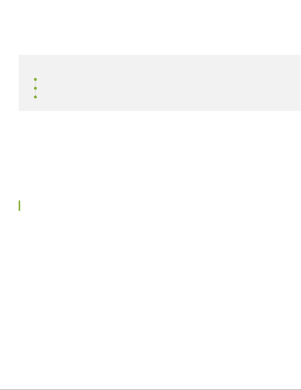
For the cooling system to function properly, the airflow around the chassis must be unrestricted. You must allow sufficient
clearance around the installed chassis for cooling and maintenance (see Figure 1).
Figure 1: Clearance Requirements for Airflow and Hardware Maintenance for an MX10008
3
If you are mounting an MX10008 in a rack with other equipment, ensure that the exhaust from other equipment does
not blow into the intake vents of the chassis.
Cooling and Airflow Requirements
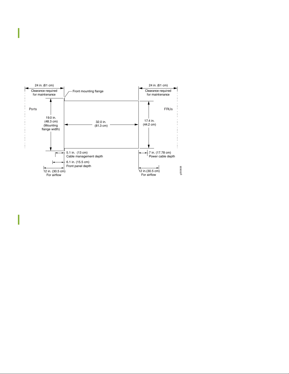
The cooling system in an MX10008 chassis consists of dual fan trays and dual fan tray controllers.
The air intake to cool the chassis is located on the port (line card) side of the chassis. Air flows into the chassis from the
ports in the Routing and Control Boards (RCBs) and line cards, through the switch fabric boards (SFBs), and exits from the
fan trays and the power supplies. This airflow is called port-to-FRU cooling or airflow out (AFO). See Figure 2.
Page 4
Figure 2: Airflow Through an MX10008
g050607
Side view
FRUsPor t s
Control boards
Linecards
SIBs
Fan
trays
Fan tray controllers
Power
supplies
Follow these guidelines:
For the cooling system to function properly, the airflow around the chassis must be unrestricted.
•
4
If you are mounting an MX10008 in a rack with other equipment, ensure that the exhaust from other equipment does
•
not blow into the intake vents of the chassis.
Leave at least 24 in. (61 cm) both in front of and behind the MX10008 for service personnel to remove and install
•
hardware components. To be NEBS GR-3160 compliant, allow at least 30 in. (76.2 cm) in front of the rack and 24 in.
(61 cm) behind the rack.
Step 2–Unpacking the MX10008
NOTE: The chassis is maximally protected inside the shipping box. Do not unpack it until you are ready to begin
installation.
Ensure that you have the following parts and tools available to unpack the MX10008:
A 13/32 in. (10 mm) open-end wrench or socket wrench to remove the bracket bolts from the shipping pallet
•
A box cutter or packing knife to slice open the nylon straps and tape that seal the crate and boxes
•
The chassis ships in a cardboard box that has a two-layer wooden pallet base with foam cushioning between the layers.
The router chassis is bolted to the pallet base.
The shipper has the option to either ship the front panel separately or to ship along with the chassis. If the front panel
arrives with the chassis, set aside the front panel box until you are ready to verify the contents of the order.
Page 5
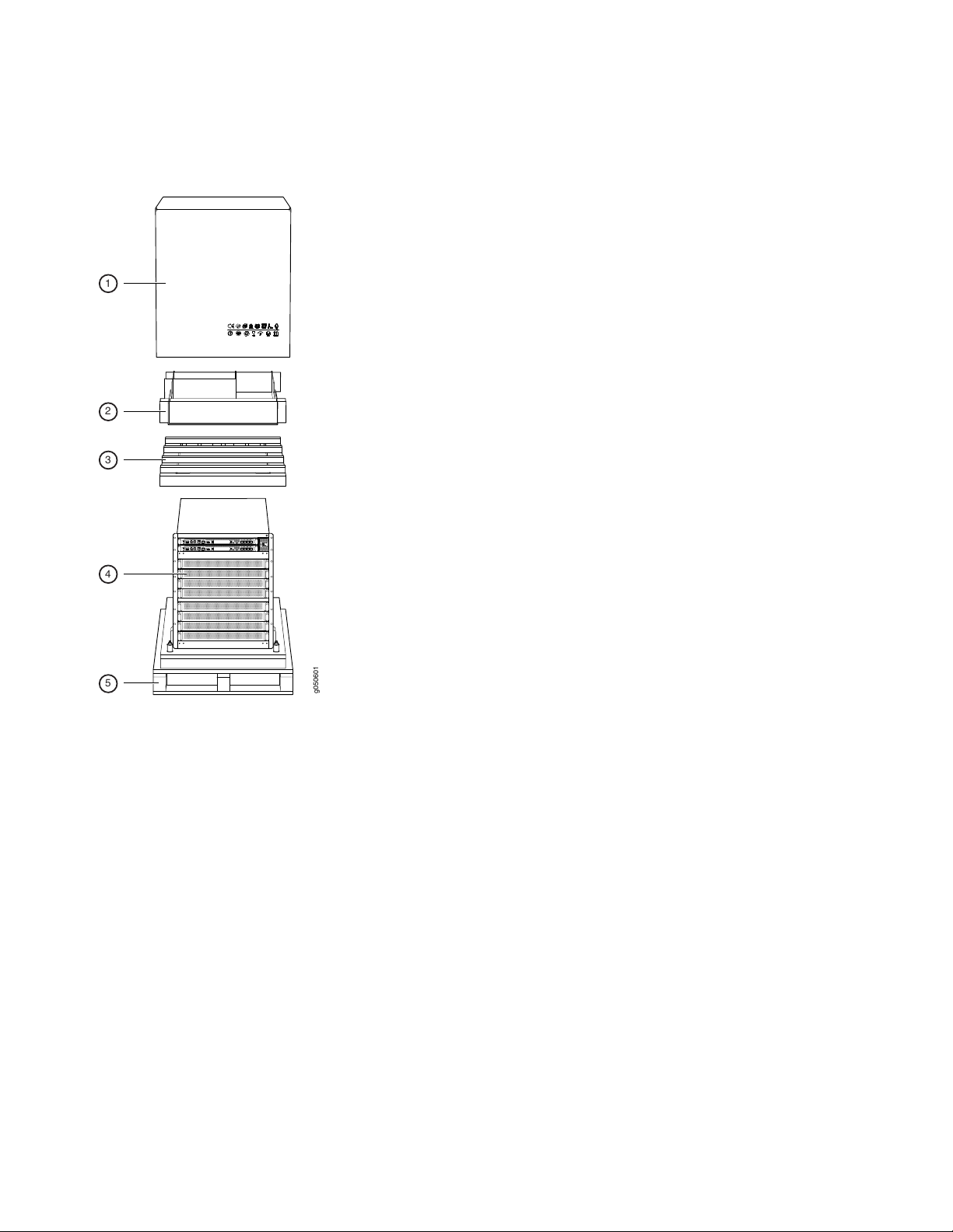
To unpack the chassis (see Figure 3):
g050601
1
2
3
4
5
Figure 3: Shipping Crate and Accessory Box
5
1. Move the shipping box to a staging area as close to the installation site as possible. While the chassis is bolted to the
pallet, you can use a forklift or pallet jack to move it. Make sure there is enough space to remove components from
the chassis.
2. Position the shipping box with the arrows pointing up.
3. Slice the nylon straps with the box cutter that hold the shipping boxes to the pallet.
4. Lift the shipping box off the chassis.
5. Remove the cardboard accessory box.
6. Remove the foam padding from the top of the box.
7. Remove the plastic cover from the router chassis.
8. Use a 13/32 in. (10 mm) open-end or socket wrench to remove the four sets of bracket bolts that secure the chassis
to the shipping pallet (see Figure 4).
Page 6
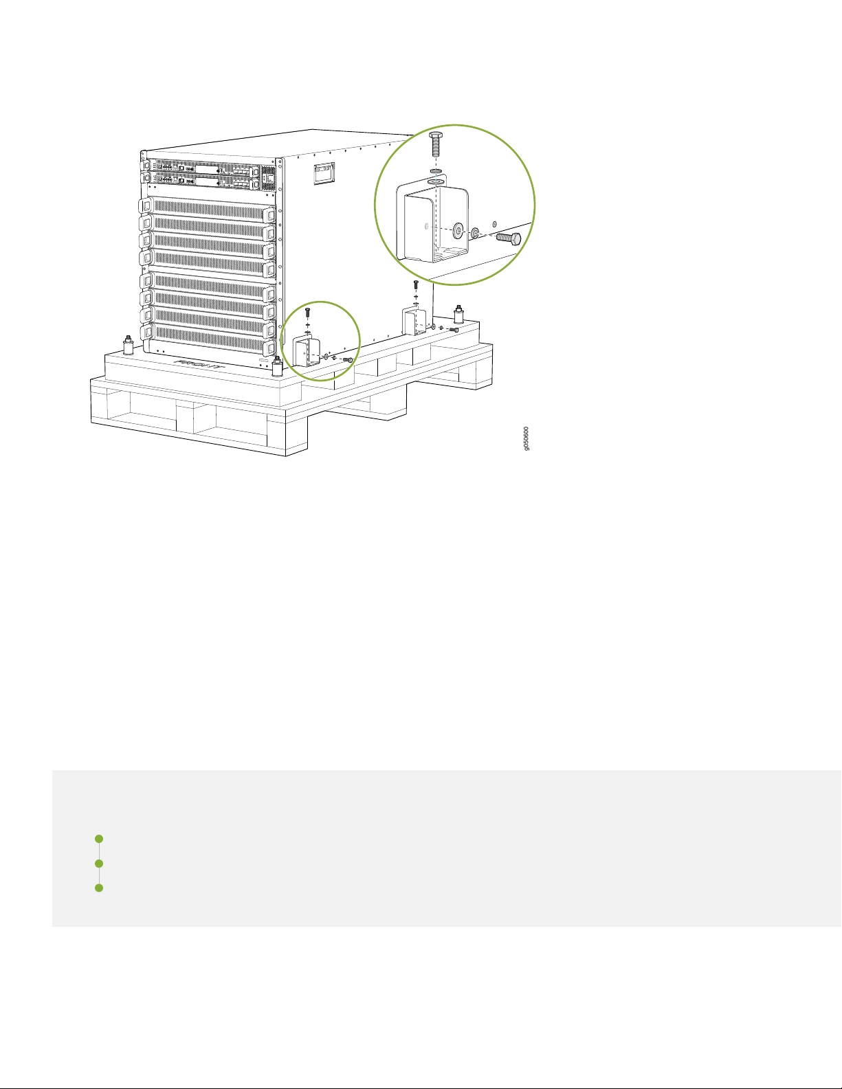
Figure 4: Bracket Bolt Removal
g050600
6
9. Unpack the accessory box and lay out the contents so that they are ready for use.
10. Verify that your order includes all appropriate parts.
11. Store the brackets and bolts inside the accessory box.
12. Save the shipping box and packing materials in case you need to move or ship the router at a later time.
Step 3–Mounting the router Chassis
IN THIS SECTION
Installing the Mounting Hardware | 7
Mounting the MX10008 Using a Mechanical Lift | 8
Manually Mounting an MX10008 | 11
To install the MX10008, first install the mounting hardware and then perform one of these two procedures:
Page 7

Installing the Mounting Hardware
Install the mounting hardware on the rack before installing the router. MX10008 comes with a four-piece set of mounting
brackets that supports the chassis in the rack.
NOTE: Two-post installation racks are not supported.
The four mounting bracket pieces are:
1 left front mounting bracket. The bracket is labeled LEFT FRONT on the side of the bracket that faces the interior of
•
the rack, near the holes for attaching the bracket to the rack.
1 right front mounting bracket. The bracket is labeled RIGHT FRONT on the side of the bracket that faces the interior
•
of the rack, near the holes for attaching the bracket to the rack.
2 rear mounting brackets. These brackets are labeled REAR on the side of the bracket that faces the interior of the rack,
•
near the holes for attaching the bracket to the rack. The rear brackets are interchangeable; you can use either of the
rear brackets with the right or left front-mounting bracket.
7
Ensure that you have the following parts and tools available to install the mounting brackets:
A Phillips (+) screwdriver, number 1, 2, or 3, depending on the size of your rack-mounting screws
•
A Phillips (+) screwdriver, number 2, to install the screws that connect the rear-mounting and front-mounting brackets
•
16 mounting screws appropriate for your rack to attach the 4 mounting bracket pieces to the rack
•
When you install the mounting brackets, the adjustable portion of the brackets overlap. Use the overlap area to adjust
the total bracket length to fit any of the four standard rack sizes: 19 in. (483 mm), 23.62 in. (600 mm), 30 in. (762 mm), or
31.5 in. (800 mm).
To install the mounting brackets in a four-post rack:
1. Remove the mounting brackets from the accessory box.
2. Decide where to place the chassis in the rack. If the rack is empty, mount the router in the lowest possible location.
See “Rack-Mounting Requirements” on page 2.
3. Position the left front adjustable mounting bracket at the desired position in the left side of the rack and line up its
front screw holes with the holes in the rack. Use four mounting screws appropriate for your rack to attach the left
front bracket to the rack.
4. Position one of the rear brackets at the left rear of the rack on the same level as the left front bracket, so that the rear
bracket overlaps with the left front bracket. The screw holes for connecting the front and rear brackets should overlap.
Use four mounting screws appropriate for your rack to attach the rear bracket to the rack.
5. Connect left front and rear brackets (see Figure 5):
a. Insert six of the screws provided with the mounting brackets into the overlapping bracket holes.
Page 8
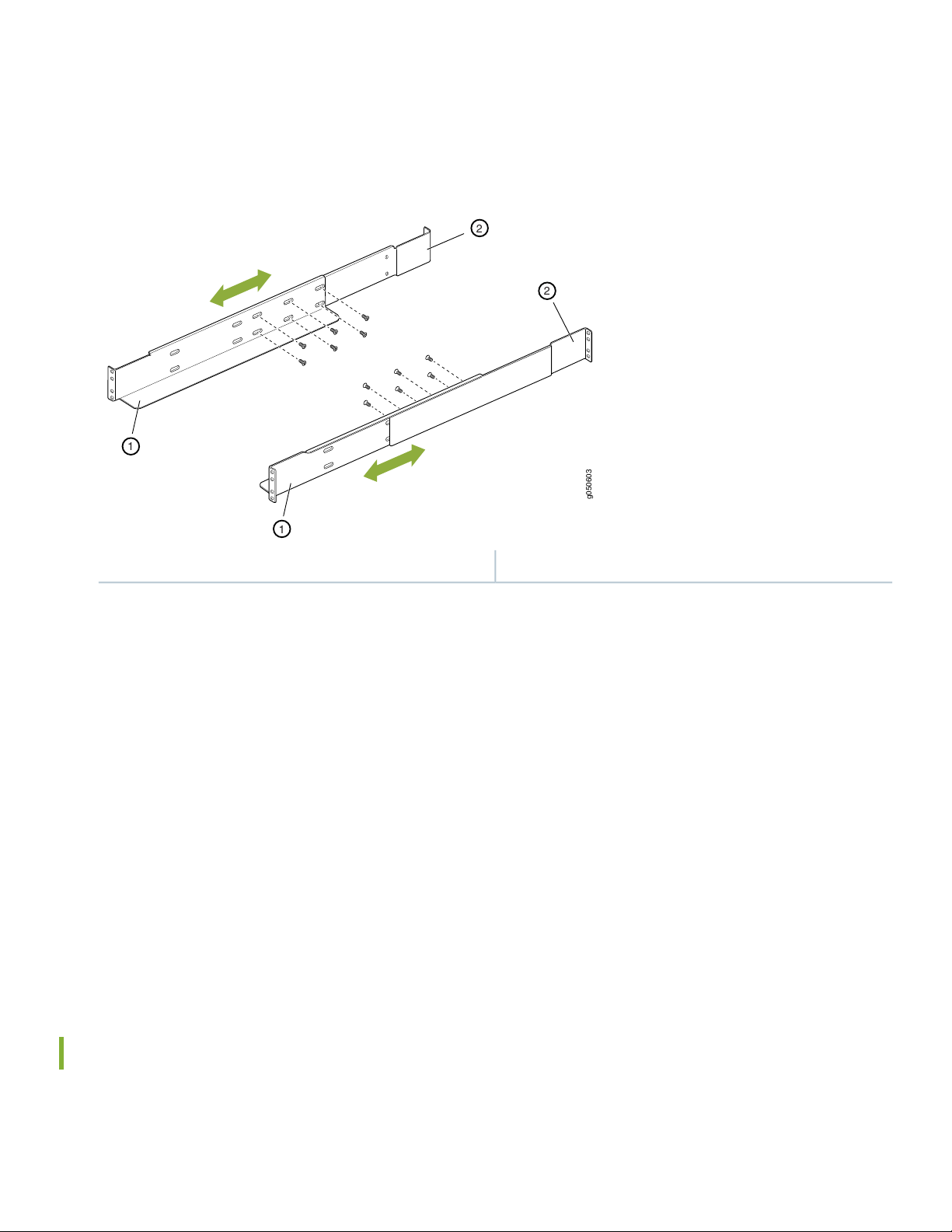
b. Hand-tighten the screws fully (to 12–16 in.-lb torque) using a number 2 Phillips screwdriver.
g050603
1
2
2
1
Figure 5: Mounting Brackets for 4-Post Rack Installation
8
2—1— Rear-adjustable mounting bracketsFront-adjustable mounting brackets
6. Position the right front-adjustable mounting bracket at the desired position in the right side of the rack opposite the
installed left front bracket, so that it is on the same rack level as the left bracket. If the right and left front brackets are
not on the same level, the chassis will rest at an angle in the rack instead of resting flat and level. Line up the right
bracket's front screw holes with the holes in the rack. Use four mounting screws appropriate for your rack to attach
the right front bracket to the rack.
7. Position the other rear bracket at the right rear of the rack on the same level as the right front bracket, so that the rear
bracket overlaps with the right front bracket. The screw holes for connecting the front and rear brackets should overlap.
Use four mounting screws appropriate for your rack to attach the rear bracket to the rack.
8. Connect the right front and rear brackets (see Figure 5):
a. Insert six of the screws provided with the mounting brackets into the overlapping bracket holes.
b. Tighten the screws fully (to 12–16 in.-lb torque) using a number 2 Phillips screwdriver.
Mounting the MX10008 Using a Mechanical Lift
Because of the router's size and weight, we strongly recommend using a mechanical lift to install the MX10008.
Page 9
CAUTION: Do not install line cards in the chassis until after you mount the chassis securely on a rack
or cabinet.
CAUTION: Before mounting the router on a rack or cabinet, have a qualified technician verify that
the rack or cabinet is strong enough to support the router's weight and is adequately supported at the
installation site.
Ensure that you have the following parts and tools available to install the router:
A mechanical lift rated for 500 lbs. (226.8 kg)
•
14 mounting screws appropriate for your rack
•
A Phillips (+) screwdriver, number 2 or number 3, depending on the size of your rack-mounting screws
•
CAUTION: If you are installing more than one router in a rack or cabinet, install the first router at the
bottom of the rack.
9
To install the router using a mechanical lift (see Figure 6):
1. Ensure that the rack or cabinet is placed in its permanent location and is secured to the building. Ensure that the
installation site allows adequate clearance for both airflow and maintenance. For details, see “Cooling and Airflow
Requirements” on page 3.
2. Load the router onto the lift, making sure it rests securely on the lift platform.
Page 10
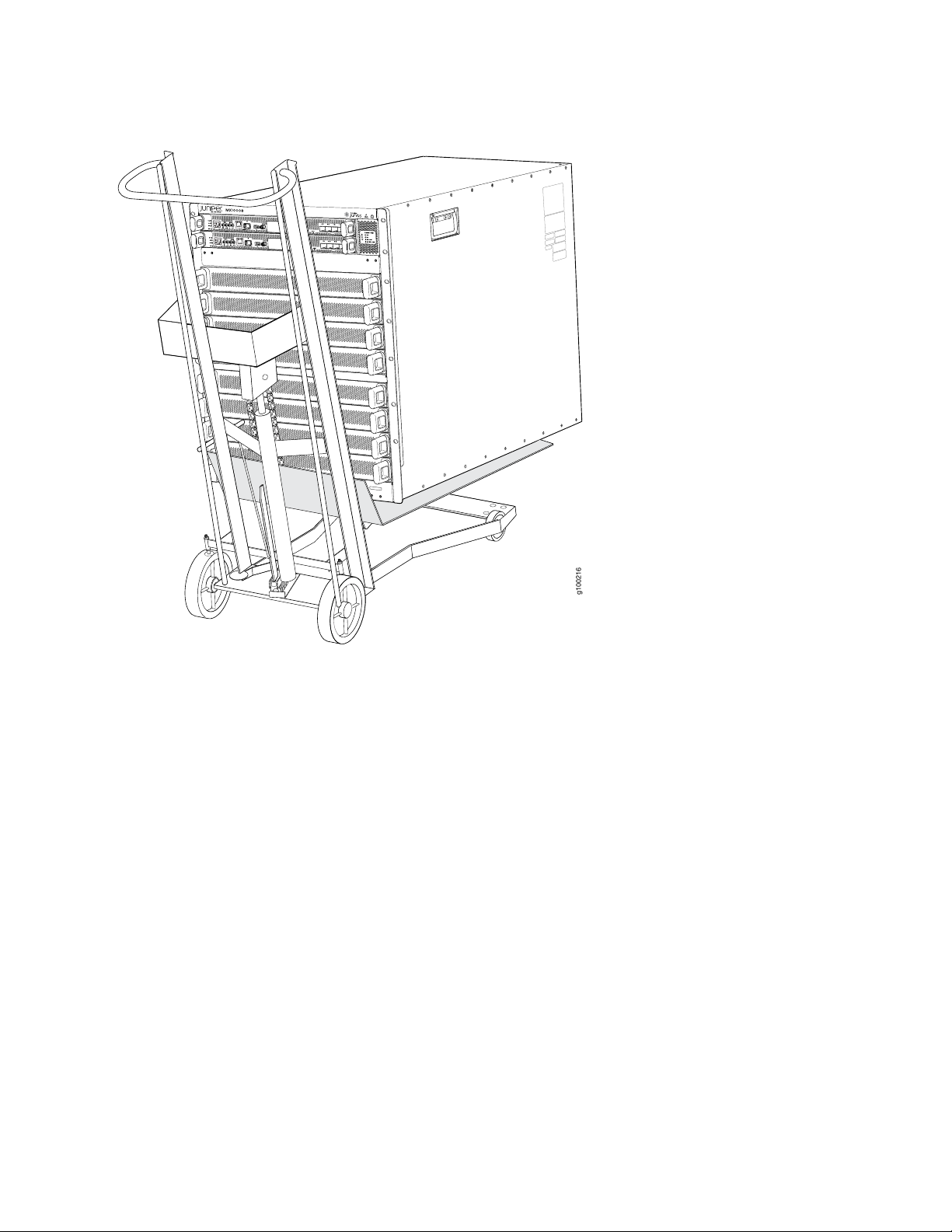
Figure 6: Loading the MX10008 into a Rack Using a Mechanical Lift
g100216
10
3. Using the lift, align the router in front of the rack, centering it in front of the mounting brackets.
4. Lift the chassis approximately 0.75 in. (1.9 cm) above the surface of the mounting brackets. Align the chassis as close
as possible to the mounting brackets.
5. Carefully slide the chassis onto the adjustable mounting brackets until the front-mounting brackets attached to the
chassis contact the rack rails. The mounting brackets ensure that the holes in the front-mounting brackets align with
the holes in the rack rails. See Figure 7.
Page 11
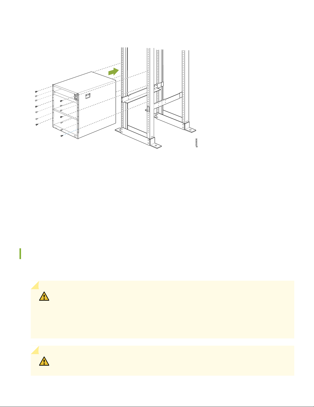
Figure 7: Attaching Front-Mounting Brackets
g050606
6. Move the lift away from the rack.
11
7. Install a mounting screw into each of the open front-mounting holes aligned with the rack, starting from the bottom.
8. Visually inspect the alignment of the router. If the router is installed properly in the rack, all the mounting screws on
one side of the rack are aligned with the mounting screws on the opposite side and the router is level.
9. After ensuring that the router is aligned properly, tighten the screws.
Manually Mounting an MX10008
If you cannot use a mechanical lift to install the router (the preferred method), you can install it manually.
CAUTION: The chassis weighs approximately 145 lb (66 kg) with only the fan tray controllers installed.
Lifting the chassis and mounting it in a rack or cabinet requires at least three people. Make sure the
chassis is empty (contains only the backplane) before you lift it.
The chassis has two handles that are designed for subtle positioning of the chassis. Do not lift the
chassis by the handles.
CAUTION: Before front-mounting the router in a rack, have a qualified technician verify that the rack
is strong enough to support the router's weight and is adequately supported at the installation site.
Page 12

12
Before you install the router, remove all components except the two fan tray controllers from the chassis. For details on
how to remove router components, such as routing and control boards, fan trays, power supplies, and SFBs, see the
MX10008 Universal Routing Platform Hardware Guide.
Ensure that you have the following parts and tools available to install the router:
14 mounting screws appropriate for your rack
•
A Phillips (+) screwdriver, number 2 or number 3, depending on the size of your rack-mounting screws
•
To install the router in the rack or cabinet:
CAUTION: If you are installing more than one router in a rack or cabinet, install the first one at the
bottom of the rack. Do not attempt to install a router manually in an upper position in a rack or cabinet.
1. Ensure that the rack or cabinet is placed in its permanent location and is secured to the building.
2. Align the router in front of the rack or cabinet, centering it in front of the adjustable mounting brackets. Use a pallet
jack if one is available.
3. With one person on each side and one person in the rear, hold the bottom of the chassis and carefully lift it onto the
adjustable mounting brackets installed in a four-post rack. See Figure 8.
WARNING: To prevent injury, keep your back straight and lift with your legs, not your back. Do
not twist your body as you lift. Balance the load evenly and be sure that your footing is firm.
Page 13

Figure 8: Lifting the MX10008 Without Using a Mechanical Lift
g009478
13
4. Carefully slide the router onto the mounting brackets until the front-mounting brackets attached to the chassis contact
the rack rails. The mounting brackets ensure that the holes in the front-mounting brackets attached to the chassis align
with the holes in the rack rails.
5. Install a mounting screw into each of the open front-mounting holes aligned with the rack, starting from the bottom.
6. Visually inspect the alignment of the chassis. If the chassis is installed properly in the rack, all the mounting screws on
one side of the rack are aligned with the mounting screws on the opposite side and the router is level.
7. After ensuring that the router is aligned properly, tighten the screws.
Page 14

Figure 9: Installing an MX10008 in a 4-Post Rack
g050606
After you install the mounting screws and securely bolt the chassis to the rack, reinstall the components in the chassis.
For information on how to install router components, see the MX10008 Universal Routing Platform Hardware Guide.
14
Step 4–Installing Line Cards
MX10008 line cards are field-replaceable units (FRUs) that can be installed in any of the line card slots on the front of the
chassis. The line cards are hot-insertable and hot-removable: You can remove and replace them without powering off the
router or disrupting router functions.
Ensure that you have the following parts and tools available to install a line card in the router:
•
ESD grounding strap
•
Page 15

g100217
MX10008
1
g050586
15
Phillips (+) screwdriver, number 2
•
To install a line card in the router chassis:
1. Attach the ESD grounding strap to your bare wrist and connect the strap to the ESD point on the router chassis. The
ESD point is located above the status LED panel on the front of the router chassis. See Figure 10.
Figure 10: ESD Point on the Chassis Front
2. Remove the cover panel by grasping the handles and pulling straight out to expose the slot for the line card. See
Figure 11.
Figure 11: Removing the Cover Panel for a Line Card
Page 16

CAUTION: Do not lift the line card by holding the edge connectors or the handles on the faceplate.
g100213
Neither the handles or the edge connectors can support the weight of the line card. Lifting the line
card by the handles or edge connectors might bend them, which would prevent the line cards from
being properly seated in the chassis. See Figure 12.
Figure 12: Line Card Connectors
1—Connectors
16
3. Remove the line card from the electrostatic bag and inspect it for any damage before installing it into the chassis.
4. Grasp and lift the line card by the sides.
5. Slide the line card all the way into the slot until the handle holes align. See Figure 13.
Figure 13: Inserting a Line Card into the Slot and Rotating the Handles
6. Screw the line card into the chassis by rotating the handles until the card is fully seated and the handles are vertical.
7. Bring the line card online:
Page 17

user@router>
request chassis fpc slot slot-number online
You can install the optional cable management kit after the card is installed.
Step 5–Installing the Front Panel
The front panel is required on the MX10008 to protect fiber optic cabling and to provide additional protection from
electromagnetic interference (EMI). The front panel can be installed with or without the optional cable management
system.
Ensure you have the following tools and parts before you begin:
17
A Phillips (+) screwdriver, number 2
•
Front panel (provided with the router chassis)
•
Right base bracket (provided)
•
Left base bracket (provided)
•
2 interchangeable latch brackets (provided)
•
8 Phillips flat head mounting screws (provided)
•
To install the front panel:
1. Remove the plastic bag that is taped to the front panel, which holds the brackets and screws.
2. Use the Phillips screwdriver to attach two mounting screws to the left base bracket at the bottom left side of the
chassis frame. The base brackets are larger than the latch brackets.
Page 18

NOTE: The right and left base bracket cannot be interchanged (see Figure 14).
g050602
2
1
3
g050626
Figure 14: Front Panel Mounting Hardware
3—1— Left base bracketLatch brackets
2—Right base bracket
18
3. Use the Phillips screwdriver to attach two mounting screws to the right base bracket at the bottom right side of the
chassis frame.
4. Use the Phillips screwdriver to attach two mounting screws to the latch bracket at the top left of the chassis frame
(see Figure 15).
Figure 15: Attaching Front Panel Brackets
Page 19

g009481
19
5. Use the final two mounting screws to attach a latch bracket to the top right of the chassis frame so there are brackets
on all four corners of the front of the chassis.
6. Lift the front panel and rest it on the two bottom brackets.
7. Slide the panel back on the bracket glides until it engages on the two ramps.
8. Tilt the panel towards the chassis until it is vertical with the chassis. The blue release buttons on the side of the panel
click into place (see Figure 16).
Figure 16: Front Panel Installation
Step 6–Connecting Power to the Chassis
IN THIS SECTION
Ground the Chassis | 20
Install AC Power Supplies | 22
Install DC Power Supplies | 25
Page 20

20
Before supplying power to the MX10008, ensure you complete these tasks:
Ground the Chassis
To meet safety and electromagnetic interference (EMI) requirements and to ensure proper operation, you must connect
the MX10008 to earth ground before you connect it to power.
For installations that require a separate grounding conductor to the chassis, you must attach a protective earthing terminal
bracket on the MX10008. There are mounting holes for the terminal bracket on the left-rear side of the chassis to connect
to the earth ground (see Figure 18).
Before you connect earth ground to the protective earthing terminal of an MX10008, ensure that a licensed electrician
has attached an appropriate grounding lug to the grounding cable.
CAUTION: Using a grounding cable with an incorrectly attached lug can damage the router.
Ensure that you have the following parts and tools available:
An electrostatic discharge (ESD) grounding strap (provided).
•
Protective earthing terminal bracket (provided).
•
Grounding cable for your MX10008 (not provided)—The grounding cable must be 6 AWG (13.3 mm²), minimum 90° C
•
wire, or as permitted by the local code.
Grounding lug for your grounding cable (provided)—This bracket attaches to the lower left corner of the MX10008
•
router chassis next to PSU 5, providing a protective earthing terminal for the router. The grounding lug required is a
Panduit LCD6-10A-L or equivalent.
A Phillips screwdriver to tighten the two screws that are mounted on the chassis.
•
An AC-powered MX10008 gains additional grounding when you plug the power supply in the router into a grounded AC
power outlet by using an AC power cord appropriate for your geographical location.
To connect earth ground to an MX10008:
1. Verify that a licensed electrician has attached the cable lug (provided in the accessory kit) to the grounding cable.
2. Connect the other end of the grounding cable to a proper earth ground, such as the rack in which the router is mounted.
3. Attach an ESD grounding strap to your bare wrist, and connect the strap to the ESD grounding point next to the
earthing posts (see Figure 17).
Page 21

g050562
1
21
Figure 17: ESD Point for Chassis Rear
4. Remove the two screws on the chassis using a Phillips screwdriver.
5. Place the chassis grounding lug and cable over the PEM nuts with the cable connection pointing to the left. See Figure 18.
Figure 18: Connecting a Grounding Cable to the MX10008
6. Place the two screws over the grounding lug and grounding cable.
7. Tighten the two screws using a Phillips screwdriver.
8. Dress the grounding cable and ensure that it does not touch or block access to other device components and that it
does not drape where people can trip over it.
Page 22

g050587
22
Install AC Power Supplies
MX10008 power supplies are hot-insertable and are field-replaceable units (FRUs). You can install up to six power supplies
in an MX10008. The power supplies install in the rear of the chassis in the slots provided along the left side.
CAUTION: Do not mix AC and DC power supplies in the same chassis.
Before you install an AC power supply in the router, ensure that you have the following parts and tools available to install
an AC power supply in an MX10008:
Electrostatic discharge (ESD) grounding strap
•
Phillips (+) screwdriver, number 1
•
Power cords appropriate for your geographical location.
•
Power cord retainer clips
•
To install an AC power supply in an MX10008 :
1. Attach the electrostatic discharge (ESD) grounding strap to your bare wrist, and connect the strap to the ESD point
on the chassis. There is an ESD point located next to the protective earthing terminal and below PSU 5 on the rear
panel .
2. If the power supply slot has a cover panel on it, insert your thumb and forefinger into the finger holes, squeeze and
pull the cover out of the slot. Save the cover panel for later use. See Figure 19.
Figure 19: Removing the PSU Cover Panel
3. Taking care not to touch power supply connections, remove the power supply from its bag.
4. Peel back and remove the protective plastic wrap that covers all four sides of the power supply.
Page 23

g050568
Keep latch in open position during installation.
23
5. Ensure the power router is set to the standby (O) position. This router turns off the output voltage; it does not interrupt
AC.
6. Unscrew the captive screw in the counterclockwise direction by using the Phillips (+) screwdriver, number 1.
7. Rotate the captive screw away from the faceplate of the power supply to release the latch.
NOTE: You can install the power supplies in any slot labeled PSU 0 through PSU 5 (top to bottom).
8. Using both hands, place the power supply in the power supply slot on the rear of the system. Slide the power supply
straight into the chassis until the power supply is fully seated in the slot. Ensure the power supply faceplate is flush
with any adjacent power supply faceplates or power supply cover panels (see Figure 20).
9. Push the captive screw into the power supply faceplate. Ensure that the screw is seated inside the corresponding hole
on the faceplate.
10. Tighten the captive screw by turning it clockwise by using the Phillips (+) screwdriver, number 1. When the screw is
completely tight, the latch locks into the router chassis.
Figure 20: Installing an MX10008 AC Power Supply
11. Locate two power cords shipped with the router; the cords have plugs appropriate for your geographical location.
Page 24

ON
FAULT
PWROK
INP2
INP1
1
2
g050569
ON
FAULT
PWROK
INP2
INP1
1
2
1 2
24
12. Attach each power cord to a dedicated AC power source outlet.
13. Squeeze the two sides of the power cord retainer clip and insert the ends of the clip into the holes in the bracket on
each side of the AC appliance inlets on the AC power supply faceplate. See Figure 21.
14. Insert the power cord coupler into the power supply.
Each AC power supply has two independent 16 A rated AC inlets on the faceplate. Each inlet must be connected to a
dedicated AC power feed to achieve 2N source redundancy. A single connection can be used if redundancy is not a
requirement.
15. Fasten the cord retainer by lowering the clip over the cord and pushing the cord into the adjustment nut of the cord
retainer. Rotate the nut until it is tight against the base of the cord. See Figure 21.
NOTE: Route all the AC power supply cords away from the fan trays. Make sure that the power cords do
not obstruct the fan trays.
Figure 21: Power Cord and Retainer Clip
WARNING: Ensure that the power cords do not block access to router components or drape where
people can trip on them.
2—1— Enable switch for INP2Enable switch for INP1
16. If the AC power source outlets have a power switch, set them to the on (|) position.
17. Move the enable switches for input 1 and input 2 to the ON position.
Page 25

25
18. Verify that the INP1 and INP2 LEDs on the power supply faceplate are lit and are on steadily.
19. Press the power switch to the on (|) position.
Install DC Power Supplies
MX10008 power supplies are hot-insertable and are field-replaceable units (FRUs). You can install up to six power supplies
in an MX10008. The power supplies install in the rear of the chassis in the slots provided along the left side.
CAUTION: Do not mix AC and DC power supplies in the same chassis.
1. Before you install a DC power supply in the chassis, ensure that you have followed all safety warnings and cautions:
WARNING: Before performing DC power procedures, ensure that power is removed from the DC
circuit. To ensure that all power is off, locate the circuit breaker on the panel board that services
the DC circuit, switch the circuit breaker to the OFF position, and tape the switch handle of the
circuit breaker in the OFF position.
CAUTION: Before you connect power to the router, a licensed electrician must attach a cable lug
to the grounding and power cables that you supply. A cable with an incorrectly attached lug can
damage the router (for example, by causing a short circuit).
CAUTION: To meet safety and electromagnetic interference (EMI) requirements and to ensure
proper operation, you must connect MX10008 routers to earth ground before you connect them
to power. For installations that require a separate grounding conductor to the chassis, use the
protective earthing terminal on the router chassis to connect to earth ground. For instructions on
connecting an MX10008 router to ground using a separate grounding conductor, see “Ground the
Chassis” on page 20.
2. Ensure that you have the following parts and tools available to install a DC power supply in an MX10008:
Electrostatic discharge (ESD) grounding strap
•
DC power source cables (not provided) with the cable lugs (provided) attached
•
The provided terminal lugs in an MX10008 are sized for 4 AWG (21.1 mm2) power source cables. The DC power
source cables that you provide must be 4 AWG (21.1 mm2), minimum 60°C wire. We recommend that you install
heat-shrink tubing insulation around the power cables and lugs.
Page 26

26
13/32 in. (10 mm) nut driver or socket wrench
•
Phillips (+) screwdrivers, numbers 1 and 2
•
Multimeter
•
To install a DC power supply in an MX10008 (see Figure 24):
1. Attach the electrostatic discharge (ESD) grounding strap to your bare wrist, and connect the strap to the ESD point
on the chassis. There is an ESD point located next to the protective earthing terminal and below PSU 5 on the rear
panel .
2. Taking care not to touch power supply components, pins, leads, or solder connections, remove the power supply from
its bag.
3. Peel back and remove the protective plastic wrap that covers all four sides of the power supply.
4. Ensure the power switch is set to the standby (O) position. This switch turns off the output voltage; it does not interrupt
DC.
5. Remove the plastic cable cover from the DC power input terminals by using the Phillips (+) screwdriver, number 2, to
loosen the screws.
6. Remove the nuts from each DC power input terminal, using the 13/32 in. (10 mm) nut driver or socket wrench to
loosen the nuts.
7. Ensure that the power source circuit breaker is open so that the voltage across the DC power source cable leads is
0 V and that the cable leads do not become active while you are connecting DC power.
8. Verify that the DC power cables are correctly labeled before making connections to the power supply. In a typical
power distribution scheme where the return is connected to chassis ground at the battery plant, you can use a multimeter
to verify the resistance of the –48V and RTN DC cables to chassis ground:
The cable with very high resistance (indicating an open circuit) to chassis ground is negative (–) and will be installed
•
on the –48V (input) DC power input terminal.
The cable with very low resistance (indicating a closed circuit) to chassis ground is positive (+) and will be installed
•
on the RTN (return) DC power input terminal.
CAUTION: You must ensure that power connections maintain the proper polarity. The power
source cables might be labeled (+) and (–) to indicate their polarity. There is no standard color coding
for DC power cables.
9. Install each power cable lug on the DC power input terminal, securing it with the nut (see Figure 22). Apply between
24 in.-lb (2.7 Nm) and 25 in.-lb (2.8 Nm) of torque to each nut. [Use the 13/32 in. (10 mm) nut driver or socket wrench.]
a. Secure each positive (+) DC source power cable lug to the RTN (return) DC power input terminal.
Page 27

27
b. Secure each negative (–) DC source power cable lug to the –48V (input) DC power input terminal.
Each power supply has two independent sets of DC power input terminals (INPUT 1: RTN –48V/–60V: and INPUT
2: : RTN –48V/–60V). For feed redundancy, each power supply must be powered by dedicated power feeds derived
from feed INPUT 1 and feed INPUT 2. This configuration provides the commonly deployed INPUT 1 / INPUT 2 feed
redundancy for the router.
Figure 22: Connecting the DC Power Supply Cables to an MX10008
10. Install the plastic cable cover over each set of power cables by using the Phillips (+) screwdriver, number 2, to tighten
the screw.
11. If the power supply slot on the chassis has a cover panel on it, insert your thumb and forefinger into the finger holes,
squeeze, and pull the cover out of the slot. Save the cover panel for later use (see Figure 23).
Page 28

Figure 23: Removing the PSU Cover Panel
g050587
12. Unscrew the captive screw in the counterclockwise direction by using the Phillips (+) screwdriver, number 1.
13. Pull the captive screw away from the faceplate of the power supply to release the latch.
28
NOTE: You can install the power supplies in any slot labeled PSU 0 through PSU 5 (top to bottom).
14. Using both hands, place the power supply in the power supply slot on the rear of the router. Slide the power supply
straight into the chassis until the power supply is fully seated in the slot. Ensure the power supply faceplate is flush
with any adjacent power supply faceplates or power supply cover panels (see Figure 24).
15. Push the captive screw into the power supply faceplate. Ensure that the screw is seated inside the corresponding hole
on the faceplate.
16. Tighten the captive screw by turning it clockwise by using the Phillips (+) screwdriver, number 1. When the screw is
completely tight, the latch locks into the router chassis.
Page 29

Figure 24: Installing an MX10008 DC Power Supply
g050574
29
2—1— Source input 2 enable switchSource input 1 enable switch
17.
WARNING: Ensure that the power cords do not block access to router components or drape where
people can trip on them.
NOTE: Route all the DC power supply cords away from the fan trays. Make sure that the power cords do
not obstruct the fan trays.
18. Set the enable switches for input 1 and input 2 (see Figure 25).
Set both enable switches to the | (on) position when using both source inputs. When not using source redundancy, set
the unused source to the O (off) position. The LED turns red and indicates an error if a source input is not in use and
the enable switch is | (on).
Page 30

Figure 25: Setting the Enable Switches for the Power Source
2—1— Source input 2Source input 1
19. Verify that the input 1 and 2 LEDs on the power supply faceplate are lit and are on steadily.
30
20. Press the power switch to the on (|) position.
Step 7–Connecting to the Network
You can configure and manage the MX10008 by using a dedicated console. Every Routing and Control Board (RCB) has
a console port with an RJ-45 connector. Use the console port to connect the device to the management console or to a
console server. The console port accepts a cable with an RJ-45 connector.
Ensure that you have an Ethernet cable with an RJ-45 connector available. An RJ-45 cable and an RJ-45 to DB-9 serial
port adapter are supplied with the device.
NOTE: If your laptop or PC does not have a DB-9 male connector pin and you want to connect your laptop or
PC directly to the device, use a combination of the RJ-45 to DB-9 female adapter supplied with the device and
a USB to DB-9 male adapter. You must provide the USB to DB-9 male adapter.
To connect the MX10008 to the network using the console port:
1. Connect one end of the Ethernet cable into the console port labeled CONSOLE on the Routing and Control Board
(RCB).
2. Connect the other end of the Ethernet cable into the console server.
Page 31

Figure 26: Connecting a router to a Management Console Through a Console Server
g020547
PC
To Console Port Console Server
g020570
To Console port
PC
Figure 27: Connecting a router Directly to a Management Console
31
Step 8–Performing Initial Configuration
You must perform the initial configuration of an MX10008 router through the console port using the command-line
interface (CLI).
Before you begin connecting and configuring the router, set the following parameter values on the console server or PC:
Baud Rate—9600
•
Flow Control—None
•
Data—8
•
Parity—None
•
Stop Bits—1
•
DCD State—Disregard
•
To connect and configure the router from the console:
1. Connect the console port to a laptop or PC using the supplied RJ-45 cable and RJ-45 to DB-9 adapter. The console
(CON) port is located on the port panel of the router.
2. Log in as root. There is no password. If the software booted before you connected to the console port, you might need
to press the Enter key for the prompt to appear.
login: root
3. Start the CLI.
Page 32

root@% cli
4. Enter configuration mode.
root> configure
5. Add a password to the root administration user account.
[edit]
root@# set system root-authentication plain-text-password
New password: password
Retype new password: password
32
6. (Optional) Configure the name of the router. If the name includes spaces, enclose the name in quotation marks (“ ”).
[edit]
root@# set system host-name host-name
7. Configure the default gateway.
[edit]
root@# set routing-options static route default next-hop address
8. Configure the IP address and prefix length for the router management interface.
[edit]
root@# set interfaces em0 unit 0 family inet address address/prefix-length
CAUTION: Although the CLI permits you to configure two management Ethernet interfaces within
the same subnet, only one interface is usable and supported.
Page 33

NOTE: The management ports, em0 (MGMT for RJ-45 or fiber connection) is found on each of the Routing
and Control Boards (RCBs) of the MX10008.
9. (Optional) Configure the static routes to remote prefixes with access to the management port.
[edit]
root@# set routing-options static route remote-prefix next-hop destination-ip retain no-readvertise
10. Enable Telnet service.
[edit]
root@# set system services telnet
NOTE: When Telnet is enabled, you cannot log in to an MX10008 through telnet using root credentials.
Root login is allowed only for SSH access.
33
11. Commit the configuration to activate it on the router.
[edit]
root@# commit
Safety Warnings Summary
This is a summary of safety warnings. For a complete list of warnings, including translations, see the MX10008 Switch
Hardware Guide at https://www.juniper.net/documentation/.
WARNING: Failure to observe these safety warnings can result in personal injury or death.
Permit only trained and qualified personnel to install or replace router components.
•
Perform only the procedures described in this quick start and the MX10008 router documentation. Other services must
•
be performed only by authorized service personnel.
Before installing the router, read the planning instructions in the MX10008 router documentation to make sure that
•
the site meets power, environmental, and clearance requirements for the router.
Page 34

Before connecting the router to a power source, read the installation instructions in the MX10008 router documentation.
g040300
•
A base AC configuration is 280 lb (127 kg) and redundant AC configurations can weigh 322 lb (146.06 kg). Installing the
•
MX10008 router in a rack or cabinet requires either a mechanical lift or three people to lift the router and another
person to secure it to the rack. To prevent injury, keep your back straight and lift with your legs, not your back.
If the rack or cabinet has stabilizing devices, install them in the rack before mounting or servicing the router in the rack
•
or cabinet.
Before installing or after removing an electrical component, always place it component-side up on a flat antistatic mat
•
or in an electrostatic bag.
Do not work on the router or connect or disconnect cables during electrical storms.
•
Before working on equipment that is connected to power lines, remove jewelry, including rings, necklaces, and watches.
•
Metal objects heat up when connected to power and ground and can cause serious burns or become welded to the
terminals.
CAUTION: Do not place a copper transceiver in an access port directly above or below another copper
transceiver. Damage to the access ports will occur.
34
Power Cable Warning (Japanese)
The attached power cable is only for this product. Do not use this cable for another product. Contacting Juniper Networks
For technical support, see https://www.juniper.net/support/requesting-support.html.
Juniper Networks, the Juniper Networks logo, Juniper, and Junos are registered trademarks of Juniper Networks, Inc. in the
United States and other countries. All other trademarks, service marks, registered marks, or registered service marks are the
property of their respective owners. Juniper Networks assumes no responsibility for any inaccuracies in this document. Juniper
Networks reserves the right to change, modify, transfer, or otherwise revise this publication without notice. Copyright © 2021
Juniper Networks, Inc. All rights reserved. Part Number: 530-088349 Rev. 01, July 2018.
 Loading...