


MX10008 Universal Routing Platform
Published
2021-03-22
Hardware Guide

Juniper Networks, Inc.
1133 Innovation Way
Sunnyvale, California 94089
USA
408-745-2000
www.juniper.net
Juniper Networks, the Juniper Networks logo, Juniper, and Junos are registered trademarks of Juniper Networks, Inc. in
the United States and other countries. All other trademarks, service marks, registered marks, or registered service marks
are the property of their respective owners.
Juniper Networks assumes no responsibility for any inaccuracies in this document. Juniper Networks reserves the right
to change, modify, transfer, or otherwise revise this publication without notice.
MX10008 Universal Routing Platform Hardware Guide
Copyright © 2021 Juniper Networks, Inc. All rights reserved.
The information in this document is current as of the date on the title page.
ii
YEAR 2000 NOTICE
Juniper Networks hardware and software products are Year 2000 compliant. Junos OS has no known time-related
limitations through the year 2038. However, the NTP application is known to have some difficulty in the year 2036.
END USER LICENSE AGREEMENT
The Juniper Networks product that is the subject of this technical documentation consists of (or is intended for use with)
Juniper Networks software. Use of such software is subject to the terms and conditions of the End User License Agreement
(“EULA”) posted at https://support.juniper.net/support/eula/. By downloading, installing or using such software, you
agree to the terms and conditions of that EULA.

Table of Contents
1
About the Documentation | xii
Documentation and Release Notes | xii
Using the Examples in This Manual | xii
Merging a Full Example | xiii
Merging a Snippet | xiv
Documentation Conventions | xiv
Documentation Feedback | xvii
Requesting Technical Support | xvii
Self-Help Online Tools and Resources | xviii
Creating a Service Request with JTAC | xviii
iii
Overview
MX10008 System Overview | 20
MX10008 Hardware Overview | 20
Benefits of the MX10008 Router | 21
Chassis Description | 22
MX10008 Routing and Control Board | 24
MX10008 Line Card (MX10K-LC2101) | 25
Switch Fabric Boards | 25
Cooling System | 26
MX10008 Power Supplies | 27
Software on MX10008 | 30
MX10008 Configurations and Upgrade Options | 30
MX10008 Configurations | 30
Upgrade Kits | 33
MX10008 Components and Configurations | 36
MX10008 Component Redundancy | 38

MX10008 Hardware and CLI Terminology Mapping | 39
MX10008 Chassis | 41
MX10008 Chassis Physical Specifications | 42
Field-Replaceable Units in an MX10008 | 45
MX10008 Status Panel LEDs | 46
MX10008 Optional Equipment | 49
MX10008 Cooling System | 51
MX10008 Cooling System and Airflow | 52
Fan Tray | 52
Fan Tray Controller | 55
Airflow Direction in the MX10008 Router | 59
MX10008 Fan Tray LEDs and Fan Tray Controller LEDs | 60
Fan Tray LEDs | 60
iv
Fan Tray Controller LEDs | 65
MX10000 Power System | 67
JNP10K-PWR-AC Power Supply | 69
JNP10K-PWR-AC2 Power Supply | 71
JNP10K-PWR-DC Power Supply | 73
JNP10K-PWR-DC2 Power Supply | 76
JNP10K-PWR-AC Power Supply LEDs | 78
JNP10K-PWR-AC2 Power Supply LEDs | 79
JNP10K-PWR-DC Power Supply LEDs | 81
JNP10K-PWR-DC2 Power Supply LEDs | 83
MX10008 Routing and Control Board Components and Descriptions | 85
MX10008 Routing and Control Board Description | 85
Routing and Control Board Functions | 86
Routing and Control Board Components | 87
MX10008 Routing and Control Board LEDs | 88

MX10008 Switch Fabric Board | 91
2
MX10008 Switch Fabric Board Description | 92
MX10008 Switch Fabric Board LEDs | 94
Line card (MX10K-LC2101) | 95
Site Planning, Preparation, and Specifications
MX10008 Site Preparation Overview | 98
MX10008 Site Preparation Checklist | 98
MX10008 Environmental Requirements and Specifications | 99
General Site Guidelines | 101
Site Electrical Wiring Guidelines | 101
MX10008 Rack Requirements | 103
MX10008 Clearance Requirements for Airflow and Hardware Maintenance | 105
v
MX10008 Chassis Physical Specifications | 106
MX10008 Power Planning | 110
Power Requirements for an MX10008 Router | 110
Calculating the Power Consumption of Your MX10008 Configuration | 111
Calculating the Number of Power Supplies Required for Your MX10008 Configuration | 112
JNP10K-PWR-AC Power Specifications | 115
JNP10K-PWR-AC2 Power Specifications | 116
MX10008 Power Cables Specifications | 117
JNP10K-PWR-AC Power Cable Specifications | 117
JNP10K-PWR-AC2 Power Cable Specifications | 120
JNP10K-PWR-AC2 Power Cable Specifications for 30-A Input | 123
JNP10K-PWR-DC Power Specifications | 125
JNP10K-PWR-DC2 Power Specifications | 126
MX10008 Grounding Cable and Lug Specifications | 127

MX10008 Transceiver and Cable Specifications | 128
3
MX10008 Optical Transceiver and Cable Support | 128
MX10008 Cable Specifications for Console and Management Connections | 129
Understanding Fiber-Optic Cable Signal Loss, Attenuation, and Dispersion | 130
Signal Loss in Multimode and Single-Mode Fiber-Optic Cables | 130
Attenuation and Dispersion in Fiber-Optic Cable | 130
Calculating the Fiber-Optic Cable Power Budget for an MX10008 Router | 131
Calculating the Fiber-Optic Cable Power Margin for an MX10008 Router | 132
MX10008 Alarm and Management Cable Specifications and Pinouts | 134
Console Port Connector Pinouts for an MX10008 Router | 134
USB Port Specifications for the MX10008 Router | 135
Management Port Connector Pinouts for the MX10008 Router | 136
RJ-45 Connector Pinouts for the External Clock Ports | 137
vi
Initial Installation and Configuration
MX10008 Installation Overview | 140
Unpacking the MX10008 Router and Components | 141
Unpacking the MX10008 | 141
Unpacking Line Cards, RCBs, and Switch Fabric Boards | 144
Comparing the MX10008 Order to the Packing List | 145
Register Products—Mandatory to Validate SLAs | 149
Installing the Mounting Hardware | 149
Installing the MX10008 into a Rack | 152
Mounting an MX10008 in a 4-Post Rack Using a Mechanical Lift | 152
Manually Mounting an MX10008 in a 4-Post Rack | 156
Installing the Front Door on an MX10008 | 160
Before You Begin | 160
Install the Front Door | 161
Install the Air Filter | 165
Connecting the MX10008 to Power | 167
Connect the MX10008 to Earth Ground | 169
Connect AC Power to an MX10008 | 171

Connect DC Power to an MX10008 | 172
4
Connecting the MX10008 to External Devices | 172
Connecting an MX10008 to a Network for Out-of-Band Management | 173
Connecting an MX10008 Router to a Management Console | 174
Configuring an MX10008 Router | 175
Maintaining Components
Field-Replaceable Units in an MX10008 | 179
Removing and Installing Routing and Control Boards | 180
Handling and Storing Routing and Control Boards | 181
Holding Routing and Control Boards | 181
Storing Routing and Control Boards | 182
Removing a Routing and Control Board | 182
vii
Installing a Routing and Control Board | 184
Removing and Installing MX10008 Cooling System Components | 187
Removing an MX10008 Fan Tray | 188
Installing an MX10008 Fan Tray | 192
Removing an MX10008 Fan Tray Controller | 195
Installing an MX10008 Fan Tray Controller | 197
Removing and Installing MX10000 Power System Components | 200
How to Remove a JNP10K-PWR-AC Power Supply | 200
How to Install a JNP10K-PWR-AC Power Supply | 205
How to Remove a JNP10K-PWR-AC2 Power Supply | 213
How to Install a JNP10K-PWR-AC2 Power Supply | 217
How to Remove a JNP10K-PWR-DC Power Supply | 224
How to Install a JNP10K-PWR-DC Power Supply | 229
How to Remove a JNP10K-PWR-DC2 Power Supply | 239
How to Install a JNP10K-PWR-DC2 Power Supply | 243

Removing and Installing MX10008 Switch Fabric Boards | 253
5
Handling and Storing MX10008 Switch Fabric Boards | 253
Holding Switch Fabric Boards | 254
Storing Switch Fabric Boards | 255
Removing an MX10008 Switch Fabric Board | 256
Installing an MX10008 Switch Fabric Board | 259
Removing and Installing MX10008 MPC Components | 264
How to Handle and Store an MX10008 MPC | 264
Handling MPCs | 264
Storing MPCs | 265
Install an MPC in an MX10008 | 266
Remove an MPC | 269
Install the Cable Management System | 272
viii
Removing and Installing Transceivers and Fiber-Optic Cables | 275
Remove a Transceiver | 276
Install a Transceiver | 278
Disconnect a Fiber-Optic Cable from a Router | 280
Connect a Fiber-Optic Cable to a Router | 281
Maintain the Fiber-Optic Cables in a Router | 282
Removing the MX10008 Router | 283
Powering Off an MX10008 Router | 283
Removing an MX10008 Router From a Four-Post Rack Using a Mechanical Lift | 286
Manually Removing an MX10008 Router from a 4-Post Rack | 287
Troubleshooting Hardware
Restoring Junos OS | 292
Creating an Emergency Boot Device | 292
Performing a Recovery Installation Using an Emergency Boot Device | 294
Alarm Messages | 296
Understanding Alarms | 296
Interface Alarm Messages | 297

Contacting Customer Support and Returning the Chassis or Components
6
7
Contact Customer Support | 299
Returning the MX10008 Chassis or Components | 299
Returning a Router or Component for Repair or Replacement | 300
Locating the Serial Number on an MX10008 Router or Component | 300
Listing the Chassis and Component Details Using the CLI | 301
Locating the Chassis Serial Number ID Label on an MX10008 | 308
Locating the Serial Number ID Labels on MX10008 Power Supplies | 308
Locating the Serial Number ID Labels on MX10008 Fan Trays and Fan Tray Controllers | 311
Locating the Serial Number ID Labels on MX10008 Routing and Control Boards | 311
Locating the Serial Number ID Labels on an MX10008 Line Card | 312
Locating the Serial Number ID Labels on an MX10008 Switch Fabric Board (SFB) | 312
Contacting Customer Support to Obtain a Return Materials Authorization for a Router or
Component | 313
ix
Packing an MX10008 Router or Component for Shipping | 314
Packing an MX10008 Chassis for Shipping | 315
Packing MX10008 Components for Shipping | 317
Safety and Compliance Information
General Safety Guidelines and Warnings | 321
Definitions of Safety Warning Levels | 322
Qualified Personnel Warning | 325
Warning Statement for Norway and Sweden | 326
Fire Safety Requirements | 326
Fire Suppression | 326
Fire Suppression Equipment | 326
Installation Instructions Warning | 328
MX10008 Chassis Lifting Guidelines | 328
Restricted Access Warning | 330
Ramp Warning | 332

Rack-Mounting and Cabinet-Mounting Warnings | 333
Grounded Equipment Warning | 339
Radiation from Open Port Apertures Warning | 340
Laser and LED Safety Guidelines and Warnings | 341
General Laser Safety Guidelines | 341
Class 1 Laser Product Warning | 342
Class 1 LED Product Warning | 343
Laser Beam Warning | 344
Maintenance and Operational Safety Guidelines and Warnings | 344
Battery Handling Warning | 346
Jewelry Removal Warning | 347
Lightning Activity Warning | 349
x
Operating Temperature Warning | 350
Product Disposal Warning | 352
General Electrical Safety Guidelines and Warnings | 353
Action to Take After an Electrical Accident | 354
Prevention of Electrostatic Discharge Damage | 355
AC Power Electrical Safety Guidelines | 356
AC Power Disconnection Warning | 358
DC Power Electrical Safety Guidelines for MX10008 Router | 358
DC Power Disconnection Warning | 360
DC Power Grounding Requirements and Warning | 362
DC Power Wiring Sequence Warning | 364
DC Power Wiring Terminations Warning | 367
Multiple Power Supplies Disconnection Warning | 370

TN Power Warning | 371
Agency Approvals and Compliance Statements | 371
Agency Approvals for the Router | 371
Compliance Statements for EMC Requirements for the Router | 372
Canada | 373
European Community | 373
Israel | 374
Japan | 374
Korea | 374
United States | 374
Nonregulatory Environmental Standards | 375
Compliance Statements for Environmental Requirements | 375
MX10008 Compliance Statements for Acoustic Noise | 375
xi
MX10016 Compliance Statements for Acoustic Noise | 376
About the Documentation
IN THIS SECTION
Documentation and Release Notes | xii
Using the Examples in This Manual | xii
Documentation Conventions | xiv
Documentation Feedback | xvii
Requesting Technical Support | xvii
Use this guide to install hardware and perform initial software configuration, routine maintenance, and
troubleshooting for the MX10008 Universal Routing Platform.
xii
After completing the installation and basic configuration procedures covered in this guide, refer to the
Junos OS documentation for information about further software configuration.
Documentation and Release Notes
To obtain the most current version of all Juniper Networks®technical documentation, see the product
documentation page on the Juniper Networks website at https://www.juniper.net/documentation/.
If the information in the latest release notes differs from the information in the documentation, follow the
product Release Notes.
Juniper Networks Books publishes books by Juniper Networks engineers and subject matter experts.
These books go beyond the technical documentation to explore the nuances of network architecture,
deployment, and administration. The current list can be viewed at https://www.juniper.net/books.
Using the Examples in This Manual
If you want to use the examples in this manual, you can use the load merge or the load merge relative
command. These commands cause the software to merge the incoming configuration into the current
candidate configuration. The example does not become active until you commit the candidate configuration.

If the example configuration contains the top level of the hierarchy (or multiple hierarchies), the example
is a full example. In this case, use the load merge command.
If the example configuration does not start at the top level of the hierarchy, the example is a snippet. In
this case, use the load merge relative command. These procedures are described in the following sections.
Merging a Full Example
To merge a full example, follow these steps:
1. From the HTML or PDF version of the manual, copy a configuration example into a text file, save the
file with a name, and copy the file to a directory on your routing platform.
For example, copy the following configuration to a file and name the file ex-script.conf. Copy the
ex-script.conf file to the /var/tmp directory on your routing platform.
system {
scripts {
commit {
file ex-script.xsl;
}
}
}
interfaces {
fxp0 {
disable;
unit 0 {
family inet {
address 10.0.0.1/24;
}
}
}
}
xiii
2. Merge the contents of the file into your routing platform configuration by issuing the load merge
configuration mode command:
[edit]
user@host# load merge /var/tmp/ex-script.conf
load complete

Merging a Snippet
To merge a snippet, follow these steps:
1. From the HTML or PDF version of the manual, copy a configuration snippet into a text file, save the
file with a name, and copy the file to a directory on your routing platform.
For example, copy the following snippet to a file and name the file ex-script-snippet.conf. Copy the
ex-script-snippet.conf file to the /var/tmp directory on your routing platform.
commit {
file ex-script-snippet.xsl; }
2. Move to the hierarchy level that is relevant for this snippet by issuing the following configuration mode
command:
[edit]
user@host# edit system scripts
[edit system scripts]
xiv
3. Merge the contents of the file into your routing platform configuration by issuing the load merge
relative configuration mode command:
[edit system scripts]
user@host# load merge relative /var/tmp/ex-script-snippet.conf
load complete
For more information about the load command, see CLI Explorer.
Documentation Conventions
Table 1 on page xv defines notice icons used in this guide.

Table 1: Notice Icons
xv
DescriptionMeaningIcon
Indicates important features or instructions.Informational note
Caution
Indicates a situation that might result in loss of data or hardware
damage.
Alerts you to the risk of personal injury or death.Warning
Alerts you to the risk of personal injury from a laser.Laser warning
Indicates helpful information.Tip
Alerts you to a recommended use or implementation.Best practice
Table 2 on page xv defines the text and syntax conventions used in this guide.
Table 2: Text and Syntax Conventions
ExamplesDescriptionConvention
Fixed-width text like this
Italic text like this
Represents text that you type.Bold text like this
Represents output that appears on
the terminal screen.
Introduces or emphasizes important
•
new terms.
Identifies guide names.
•
Identifies RFC and Internet draft
•
titles.
To enter configuration mode, type
the configure command:
user@host> configure
user@host> show chassis alarms
No alarms currently active
A policy term is a named structure
•
that defines match conditions and
actions.
Junos OS CLI User Guide
•
RFC 1997, BGP Communities
•
Attribute

Table 2: Text and Syntax Conventions (continued)
xvi
ExamplesDescriptionConvention
Italic text like this
Text like this
< > (angle brackets)
| (pipe symbol)
Represents variables (options for
which you substitute a value) in
commands or configuration
statements.
Represents names of configuration
statements, commands, files, and
directories; configuration hierarchy
levels; or labels on routing platform
components.
variables.
Indicates a choice between the
mutually exclusive keywords or
variables on either side of the symbol.
The set of choices is often enclosed
in parentheses for clarity.
Configure the machine’s domain
name:
[edit]
root@# set system domain-name
domain-name
To configure a stub area, include
•
the stub statement at the [edit
protocols ospf area area-id]
hierarchy level.
The console port is labeled
•
CONSOLE.
stub <default-metric metric>;Encloses optional keywords or
broadcast | multicast
(string1 | string2 | string3)
# (pound sign)
[ ] (square brackets)
Indention and braces ( { } )
; (semicolon)
GUI Conventions
Indicates a comment specified on the
same line as the configuration
statement to which it applies.
Encloses a variable for which you can
substitute one or more values.
Identifies a level in the configuration
hierarchy.
Identifies a leaf statement at a
configuration hierarchy level.
rsvp { # Required for dynamic MPLS
only
community name members [
community-ids ]
[edit]
routing-options {
static {
route default {
nexthop address;
retain;
}
}
}
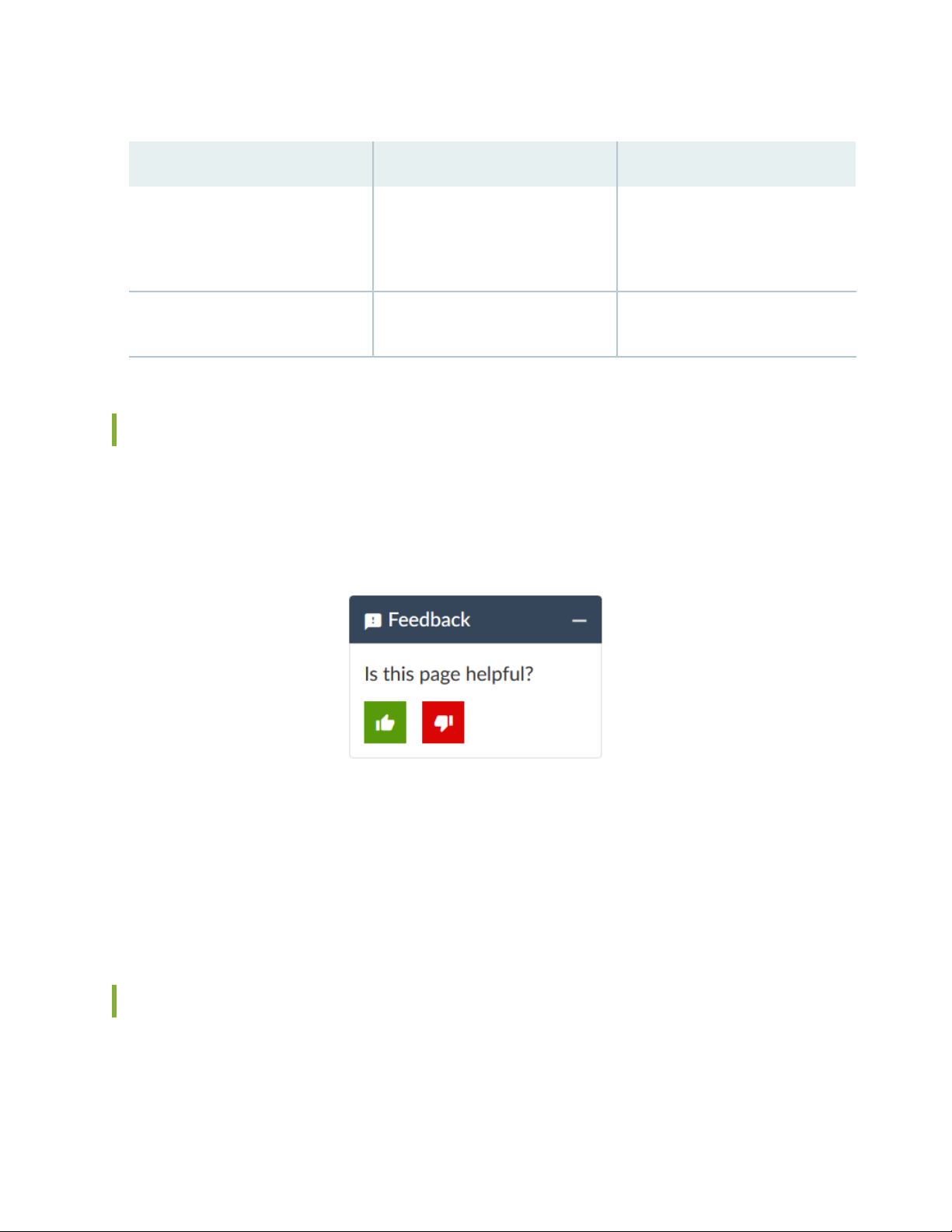
Table 2: Text and Syntax Conventions (continued)
xvii
ExamplesDescriptionConvention
Bold text like this
> (bold right angle bracket)
Represents graphical user interface
(GUI) items you click or select.
Separates levels in a hierarchy of
menu selections.
In the Logical Interfaces box, select
•
All Interfaces.
To cancel the configuration, click
•
Cancel.
In the configuration editor hierarchy,
select Protocols>Ospf.
Documentation Feedback
We encourage you to provide feedback so that we can improve our documentation. You can use either
of the following methods:
Online feedback system—Click TechLibrary Feedback, on the lower right of any page on the Juniper
•
Networks TechLibrary site, and do one of the following:
Click the thumbs-up icon if the information on the page was helpful to you.
•
Click the thumbs-down icon if the information on the page was not helpful to you or if you have
•
suggestions for improvement, and use the pop-up form to provide feedback.
E-mail—Send your comments to techpubs-comments@juniper.net. Include the document or topic name,
•
URL or page number, and software version (if applicable).
Requesting Technical Support
Technical product support is available through the Juniper Networks Technical Assistance Center (JTAC).
If you are a customer with an active Juniper Care or Partner Support Services support contract, or are

covered under warranty, and need post-sales technical support, you can access our tools and resources
online or open a case with JTAC.
JTAC policies—For a complete understanding of our JTAC procedures and policies, review the JTAC User
•
Guide located at https://www.juniper.net/us/en/local/pdf/resource-guides/7100059-en.pdf.
Product warranties—For product warranty information, visit https://www.juniper.net/support/warranty/.
•
JTAC hours of operation—The JTAC centers have resources available 24 hours a day, 7 days a week,
•
365 days a year.
Self-Help Online Tools and Resources
For quick and easy problem resolution, Juniper Networks has designed an online self-service portal called
the Customer Support Center (CSC) that provides you with the following features:
Find CSC offerings: https://www.juniper.net/customers/support/
•
Search for known bugs: https://prsearch.juniper.net/
•
xviii
Find product documentation: https://www.juniper.net/documentation/
•
Find solutions and answer questions using our Knowledge Base: https://kb.juniper.net/
•
Download the latest versions of software and review release notes:
•
https://www.juniper.net/customers/csc/software/
Search technical bulletins for relevant hardware and software notifications:
•
https://kb.juniper.net/InfoCenter/
Join and participate in the Juniper Networks Community Forum:
•
https://www.juniper.net/company/communities/
Create a service request online: https://myjuniper.juniper.net
•
To verify service entitlement by product serial number, use our Serial Number Entitlement (SNE) Tool:
https://entitlementsearch.juniper.net/entitlementsearch/
Creating a Service Request with JTAC
You can create a service request with JTAC on the Web or by telephone.
Visit https://myjuniper.juniper.net.
•
Call 1-888-314-JTAC (1-888-314-5822 toll-free in the USA, Canada, and Mexico).
•
For international or direct-dial options in countries without toll-free numbers, see
https://support.juniper.net/support/requesting-support/.

1
CHAPTER
Overview
MX10008 System Overview | 20
MX10008 Chassis | 41
MX10008 Cooling System | 51
MX10000 Power System | 67
MX10008 Routing and Control Board Components and Descriptions | 85
MX10008 Switch Fabric Board | 91
Line card (MX10K-LC2101) | 95
MX10008 System Overview
IN THIS SECTION
MX10008 Hardware Overview | 20
MX10008 Configurations and Upgrade Options | 30
MX10008 Components and Configurations | 36
MX10008 Component Redundancy | 38
MX10008 Hardware and CLI Terminology Mapping | 39
The MX10000 line of 5G Universal Routing Platforms give cloud and service providers the performance
and scalability needed to outpace increased traffic demands. MX10008 provides 10-Gigabit Ethernet,
40-Gigabit Ethernet, and 100-Gigabit Ethernet modular solutions that support up to 19.2 Tbps of
throughput. MX10008 provides redundancy and resiliency. All major hardware components including the
power system, the cooling system, the control board and the switch fabrics are fully redundant.
20
MX10008 Hardware Overview
IN THIS SECTION
Benefits of the MX10008 Router | 21
Chassis Description | 22
MX10008 Routing and Control Board | 24
MX10008 Line Card (MX10K-LC2101) | 25
Switch Fabric Boards | 25
Cooling System | 26
MX10008 Power Supplies | 27
Software on MX10008 | 30

Juniper Networks MX10008 Universal Routing Platform enables cloud and data center operators to
transition from 10-Gigabit Ethernet and 40-Gigabit Ethernet networks to 100-Gigabit Ethernet
high-performance networks. The 13 rack unit (13 U) modular chassis can provide 19.2 Tbps of throughput
and 20 Bpps of forwarding capacity. The MX10008 router has eight slots for the line cards that can support
a maximum of 768 10-Gigabit Ethernet ports, 192 40-Gigabit Ethernet ports, or 192 100-Gigabit Ethernet
ports.
The MX10008 universal router provides 2.4 Tbps per slot fabric capacity for the service providers and
cloud operators. You can deploy the MX10008 router in an IP edge network using an MX10K-LC2101
line card (ordering model number is JNP10K-LC2101).
You can deploy MX10008 in the edge of the network for the following functions:
Layer 3 Peering
•
Data Center Gateway
•
VPLS aggregation
•
Layer 3 Aggregation
•
21
Video Distribution
•
The MX10008 router is available in both base and redundant configurations for both AC and DC operation.
MX10008 features front to back airflow (also know as airflow out or AFO).
Benefits of the MX10008 Router
System capacity— MX10008 scales to 19.2 Tbps (38.4 Tbps half- duplex) in a single chassis, with support
•
for up to 768 10-Gigabit Ethernet, 192 40-Gigabit Ethernet, and 192 100-Gigabit Ethernet interfaces.
Full-scale IP and MPLS routing—MX10008 delivers the distributed peering scale of 7 million entries in
•
the forwarding information bases (FIBs, also known as forwarding table) and 80 million routing information
base entries (RIBs, also known as routing tables).
Source Packet Routing in Networking (SPRING)—SPRING on MX10008 provides additional flexibility
•
per packet source. SPRING provides features such as network path and node protection to support
MPLS fast reroute (FRR) mechanisms, enhanced network programmability, OAM functionality, simplified
network signaling, load balancing, and traffic engineering functions.
Always-on infrastructure base—MX10008 is engineered with full hardware redundancy for cooling,
•
switch fabric, and host subsystems—Routing and Control Boards (RCBs)—allowing service providers to
meet stringent service-level agreements across the core.
Nondisruptive software upgrades—The Junos operating system on MX10008 supports high availability
•
(HA) features such as graceful Routing Engine switchover (GRES), nonstop active routing (NSR), and
unified in-service software upgrade (unified ISSU), providing software upgrades and changes without
disrupting network traffic.
Chassis Description
g100208
MX10008
1
2
3
5
4
4
4
4
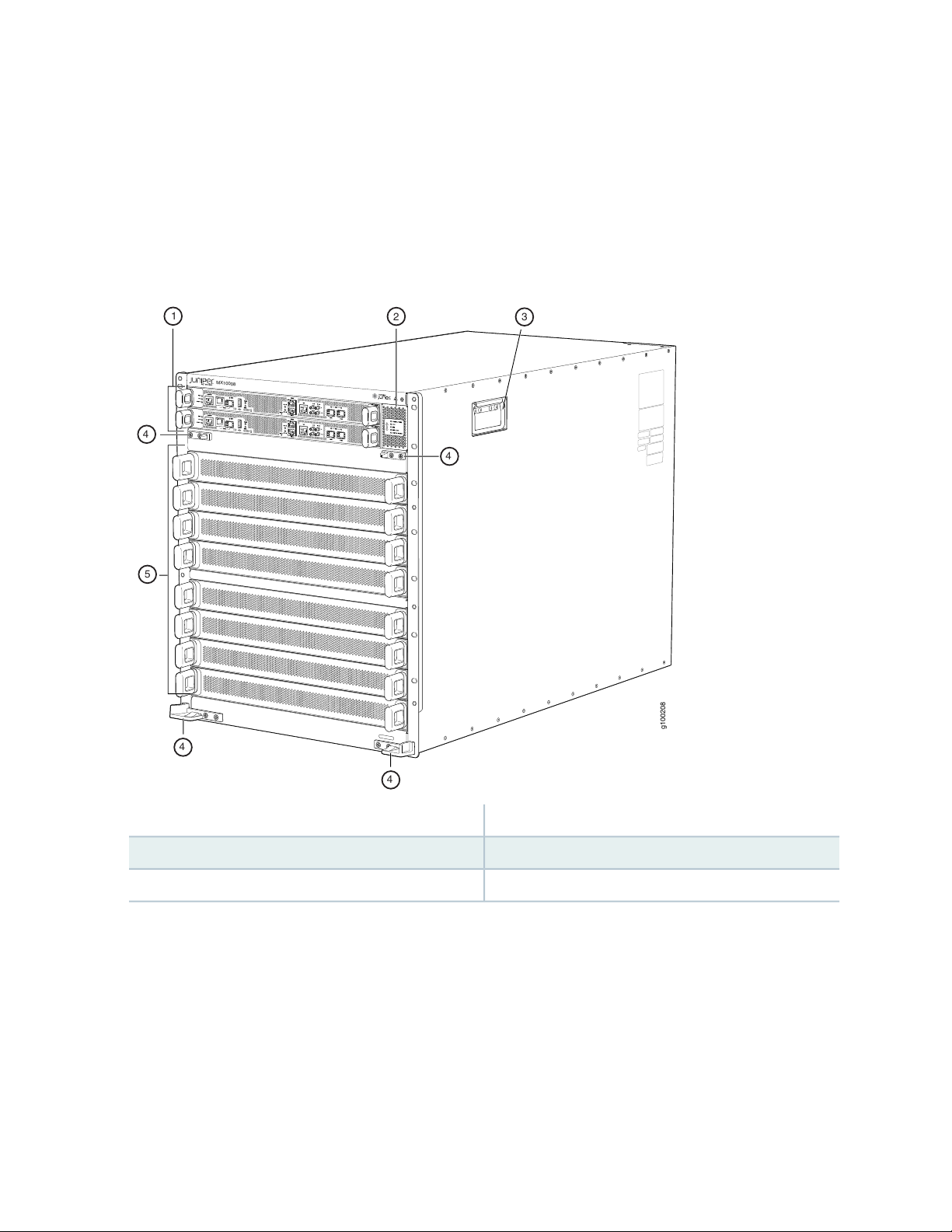
MX10008 is 13 U tall. Up to three MX10008 routers can fit in a standard 39 U rack with adequate cooling
and power. All key MX10008 router components are field-replaceable units (FRUs). Figure 1 on page 22
illustrates the key components visible from the front of the chassis.
Figure 1: MX10008 Chassis Front
22
4—1— Installation holes for the front panelRouting and Control Boards
5—2— Line card slots 0-7 (numbered top to bottom)Status LED panel
3—Handles
Some chassis ship with an enhanced power bus to support the power needs of higher wattage line cards.
Chassis with the enhanced power bus have a modified Status Panel (see “MX10008 Status Panel LEDs”
on page 46).
Figure 2 on page 23 illustrates the components that are visible from the rear of the chassis.
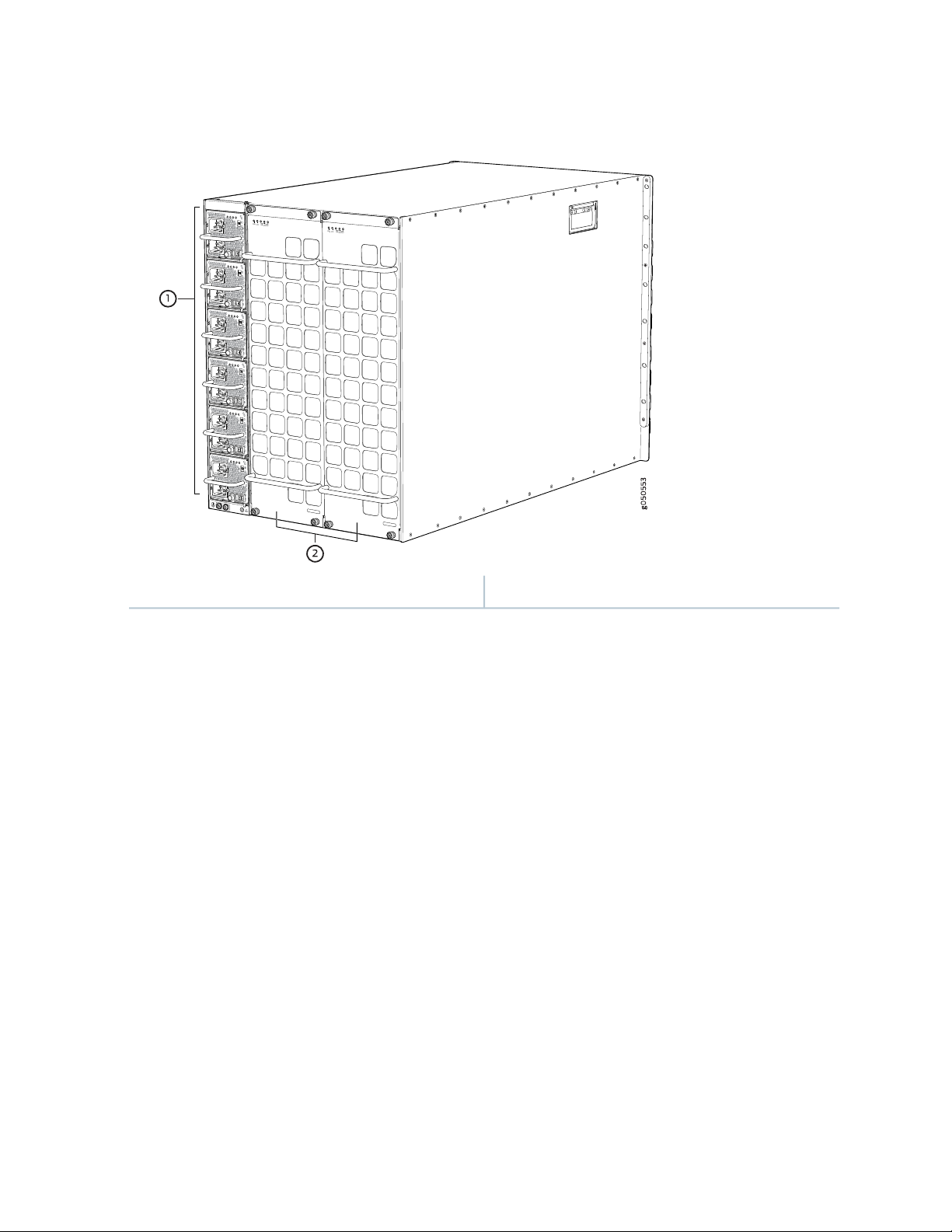
Figure 2: MX10008 Chassis Rear
FAN
FTC
SIBSTATUS
FAN
FTC
SIBSTATUS
23
2—1— Fan trays with redundant fansAC or DC power supplies
Figure 3 on page 24 illustrates the components that are internal to the chassis.

Figure 3: MX10008 Chassis Internal Components
g050555
2
1
1
24
2—1— Switch fabric boards (SFBs)Fan tray controllers
See “MX10008 Chassis Physical Specifications” on page 42 and “Field-Replaceable Units in an MX10008”
on page 45.
MX10008 Routing and Control Board
The Routing and Control board (RCB) (see Figure 4 on page 25) contains a Routing Engine and is responsible
for the system management and control in the MX10008. See “MX10008 Routing and Control Board
Description” on page 85. RCBs are FRUs that are installed in the front of the chassis in the slots labeled
CB0 and CB1. The base configuration has a single RCB while the fully redundant configuration has two
RCBs. The RCB also contains Precision Time Protocol ports and two Media Access Control Security
(MACsec) capable ports (see “MX10008 Components and Configurations” on page 36).

Figure 4: MX10008 Routing and Control Board
g100066
g100087
JNP10K-LC2101
1 2 3 4
MX10008 Line Card (MX10K-LC2101)
MX10008 has eight horizontal line card slots and supports line rate for each line card. The line cards
combine a Packet Forwarding Engine and Ethernet interfaces enclosed in a single assembly. The MX10008
line card architecture is based on a number of identical, independent Packet Forwarding Engine slices each
with 400 Gbps full-duplex throughput. Line cards are FRUs that can be installed in the line card slots
labeled 0 through 7 (top to bottom) on the front of the chassis. All line cards are hot-removable and
hot-insertable. After the hot insertion, the line card comes online automatically.
25
The MX10K-LC2101 line card is available for the MX10008. The MX10K-LC2101 line card can support
24 100-Gigabit Ethernet ports with a 28-Gbps quad smallform-factor pluggable (QSFP28) transceiver, or
24 40-Gigabit Ethernet ports with a QSFP transceiver. The MX10K-LC2101 line cards also support
10-Gigabit Ethernet interfaces. For 10-Gigabit Ethernet, you must configure the port using the channelization
command. Because there is no port-groups option for the 100-Gigabit Ethernet line card, you must use
individual port channelization commands.
Figure 5 on page 25 shows the MX10K-LC2101 line card.
Figure 5: MX10K-LC2101 Line Card
3—1— Lane LEDsOFFLINE button
4—2— Port LEDsOK/FAIL LED
Switch Fabric Boards
Five Switch Fabric Boards (SFBs) provide the necessary switching functionality to an MX10008 router. A
sixth SFB is available in the redundant configuration to provide n+1 redundancy. SFBs are installed between

the line cards and the fan trays inside of the chassis (see Figure 6 on page 26). Each MX10008 SFB has
eight connectors that match to a line card slot, eliminating the need for a backplane. When all the six SFBs
are installed, the MX10008 router has a net switching capacity of 2.4 terabytes per second (bidirectional).
See “MX10008 Switch Fabric Board Description” on page 92.
Figure 6: MX10008 SFB
26
Cooling System
The cooling system in an MX10008 router consists of two hot-removable and hot-insertable FRU fan trays
(see Figure 7 on page 27) and two fan tray controllers (see Figure 8 on page 27).
Two fan tray models and their associated fan tray controllers are available. Both models of fan tray contain
11 fans. The fan trays install vertically on the rear of the chassis and provide front to back chassis cooling.
For model differences, see “MX10008 Cooling System and Airflow” on page 52.

Figure 7: Fan Tray JNP10008-FAN
27
Figure 8: Fan Tray Controller JNP10008-FAN-CTRL
MX10008 Power Supplies
Power supplies for the MX10008 router are fully redundant, load-sharing, and hot-removable and
hot-insertable FRUs. Each MX10008 router with a base configuration has three power supplies; redundant
configurations hold a maximum of six AC, high-voltage alternating current (HVAC), DC, or high-voltage
direct current (HVDC) power supplies. Each power supply has an internal fan for cooling. See
Figure 9 on page 28 through Figure 12 on page 29.
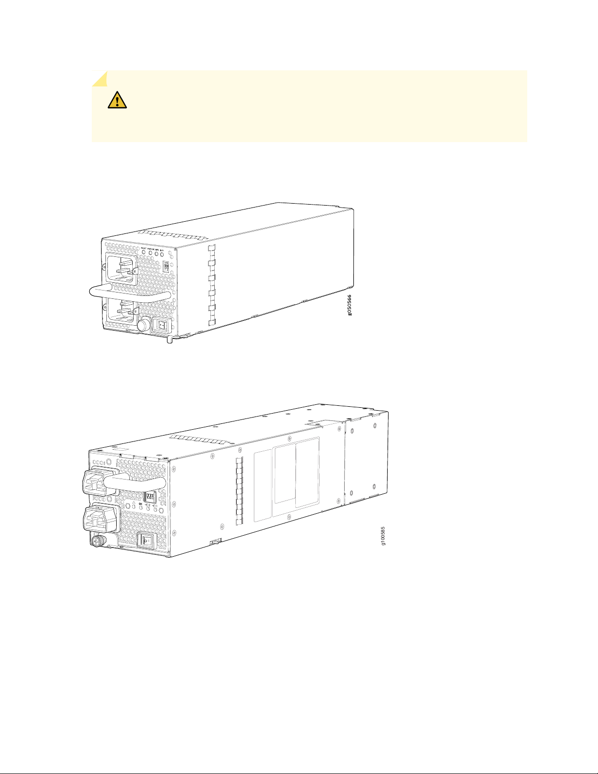
CAUTION: Do not mix power supply models in the same chassis in a running
g100585
environment. DC and HVDC can coexist in the same chassis during the hot swap of
DC for HVDC.
Figure 9: JNP10K-PWR-AC Power Supply
28
Figure 10: JNP10K-PWR-AC2 Power Supply

Figure 11: JNP10K-PWR-DC Power Supply
g050571
g100595
Figure 12: JNP10K-PWR-DC2 Power Supply
29
Table 3 on page 29 provides an overview of the differences among the power supplies.
Table 3: Power Supply Overview
WattageInput TypePower Supply Model
2700 WAC onlyJNP10K-PWR AC
5000 W, single feed; 5500 W, dual feedAC, HVAC, or HVDCJNP10K-PWR-AC2
2500 WDC onlyJNP10K-PWR DC
2750 W, single feed; 5500 W, dual feedDC onlyJNP10K-PWR-DC2

Software on MX10008
The Juniper Networks MX10008 router runs on Junos OS, which provides Layer 3 routing services. The
same Junos OS code base that runs on MX10008 router also runs on all Juniper Networks M Series,
MX Series, and T Series routers and SRX Series Services Gateways.
SEE ALSO
MX10008 Cooling System and Airflow | 52
MX10008 Chassis Physical Specifications | 42
Field-Replaceable Units in an MX10008 | 45
MX10008 Optional Equipment | 49
MX10008 Configurations and Upgrade Options
30
IN THIS SECTION
MX10008 Configurations | 30
Upgrade Kits | 33
MX10008 Configurations
Table 4 on page 31 lists the hardware configurations for a MX10008 modular chassis—base (AC and DC
versions), redundant (AC and DC versions), and redundant (HVAC, DC, and HVDC)—and the components
included in each configuration.

Table 4: MX10008 Hardware Configurations
Configuration ComponentsRouter Configuration
31
Base AC configuration
MX10008-BASE
Base AC configuration with
JNP10K-PWR-AC2 components
MX10008-BASE
Chassis
•
One RCB (JNP10K-RE1, JNP10K-RE1-LT, or JNP10K-RE1-128)
•
Two fan tray controllers (JNP10008-FAN-CTRL)
•
Two fan trays (JNP10008-FAN)
•
Three AC power supplies (JNP10K-PWR-AC)
•
Three power supply covers
•
Five SIBs (JNP10008-SF)
•
One SIB cover (JNP10008-SF-BLNK2)
•
Eight line-card covers
•
Chassis
•
One RCB (JNP10K-RE1, JNP10K-RE1-LT, or JNP10K-RE1-128)
•
Two fan tray controllers (JNP10008-FTC2)
•
Two fan trays (JNP10008-FAN2)
•
Three AC power supplies (JNP10K-PWR-AC2)
•
Three power supply covers
•
Five SIBs (JNP10008-SF)
•
One SIB cover (JNP10008-SF-BLNK2)
•
Eight line-card covers
•
Base DC configuration
MX10008-BASE
Chassis
•
One RCB (JNP10K-RE1, JNP10K-RE1-LT, or JNP10K-RE1-128)
•
Two fan tray controllers (JNP10008-FAN-CTRL)
•
Two fan trays (JNP10008-FAN)
•
Three DC power supplies (JNP10K-PWR-DC)
•
Three power supply covers
•
Five SIBs (JNP10008-SF)
•
One SIB cover (JNP10008-SF-BLNK2)
•
Eight line-card covers
•

Table 4: MX10008 Hardware Configurations (continued)
Configuration ComponentsRouter Configuration
32
Base DC configuration with
JNP10K-PWR-DC2 components
MX10008-BASE
Redundant AC configuration
MX10008-PREMIUM
Redundant AC configuration with
JNP10K-PWR-AC2 components
MX10008-PREMIUM
Chassis
•
One RCB (JNP10K-RE1, JNP10K-RE1-LT, or JNP10K-RE1-128)
•
Two fan tray controllers (JNP10008-FTC2)
•
Two fan trays (JNP10008-FAN2)
•
Three DC power supplies (JNP10K-PWR-DC2)
•
Three power supply covers
•
Five SIBs (JNP10008-SF)
•
One SIB cover (JNP10008-SF-BLNK2)
•
Eight line-card covers
•
Chassis
•
Two RCBs (JNP10K-RE1, JNP10K-RE1-LT, or JNP10K-RE1-128)
•
Two fan tray controllers (JNP10008-FAN-CTRL)
•
Two fan trays (JNP10008-FAN)
•
Six AC power supplies (JNP10K-PWR-AC)
•
Six SIBs (JNP10008-SF)
•
Eight line-card covers
•
Chassis
•
Two RCBs (JNP10K-RE1, JNP10K-RE1-LT, or JNP10K-RE1-128)
•
Two fan tray controllers (JNP10008-FTC2)
•
Two fan trays (JNP10008-FAN2)
•
Six AC power supplies (JNP10K-PWR-AC2)
•
Six SIBs (JNP10008-SF)
•
Eight line-card covers
•
Redundant DC configuration
MX10008-PREMIUM
Chassis
•
Two RCBs (JNP10K-RE1, JNP10K-RE1-LT, or JNP10K-RE1-128)
•
Two fan tray controllers (JNP10008-FAN-CTRL)
•
Two fan trays (JNP10008-FAN)
•
Six DC power supplies (JNP10K-PWR-DC)
•
Six SIBs (JNP10008-SF)
•
Eight line-card covers
•

Table 4: MX10008 Hardware Configurations (continued)
Configuration ComponentsRouter Configuration
33
Redundant DC configuration with
JNP10K-PWR-DC2 components
MX10008-PREMIUM
Chassis
•
Two RCBs (JNP10K-RE1, JNP10K-RE1-LT, or JNP10K-RE1-128)
•
Two fan tray controllers (JNP10008-FTC2)
•
Two fan trays (JNP10008-FAN2)
•
Six DC power supplies (JNP10K-PWR-DC2)
•
Six SIBs (JNP10008-SF)
•
Eight line-card covers
•
NOTE: You can install up to eight line cards that support any switch fabric compatible line card
in the MX10008.
NOTE: Line cards and the cable management system are not part of the base or redundant
configurations. You must order them separately.
NOTE: If you want to purchase additional power supplies (AC, DC, HVAC, or HVDC), SFBs, or
RCBs for your router configuration, you must order them separately.
Upgrade Kits
Most of the MX10008 hardware configurations can be upgraded to newer PTX10008 routerhardware
using an upgrade kit. Upgrading requires PTX10008-FAN2 and PTX10008-FTC2 cooling system, and 5550
W power supplies. Depending on whether you already have the newer cooling system and power supplies
will determine your upgrade kit. You can use to find the right upgrade kit.

Table 5: Upgrade Kit Matrix
34
Original
Configuration
Upgrading to
Configuration
PTX10008-BASE3MX10008-BASE
PTX10008-PREM2MX10008-BASE
JNP10K-PWR-AC and
JNP10008-FAN
JNP10008-FAN2
JNP10K-PWR-DC and
JNP10008-FAN
JNP10008-FAN 2
JNP10K-PWR-AC and
JNP10008-FAN
JNP10008-FAN2
Order Power Supply Upgrade
KitCurrent Power and Cooling
PTX10008-AC-UPGKIT and
PTX10008-B3-UPGKIT
PTX10008-B3-UPGKITJNP10K-PWR-AC2 and
PTX10008-DC-UPGKIT and
PTX10008-B3-UPGKIT
PTX10008-B3-UPGKITJNP10K-PWR-DC2 and
PTX10008-AC-UPGKIT and
PTX10008-P2-UPGKIT
PTX10008-P2-UPGKITJNP10K-PWR-AC2 and
JNP10K-PWR-DC and
JNP10008-FAN
JNP10008-FAN 2
PTX10008-PREM3MX10008-BASE
JNP10K-PWR-AC and
JNP10008-FAN
JNP10008-FAN2
JNP10K-PWR-DC and
JNP10008-FAN
JNP10008-FAN 2
PTX10008-DC-UPGKIT and
PTX10008-P2-UPGKIT
PTX10008-P2-UPGKITJNP10K-PWR-DC2 and
PTX10008-AC-UPGKIT and
PTX10008-P3-UPGKIT
PTX10008-P2-UPGKITJNP10K-PWR-AC2 and
PTX10008-DC-UPGKIT and
PTX10008-P3-UPGKIT
PTX10008-P3-UPGKITJNP10K-PWR-DC2 and

Table 5: Upgrade Kit Matrix (continued)
35
Original
Configuration
Upgrading to
Configuration
PTX10008-BASE3MX10008-PREMIUM
PTX10008-PREM2MX10008-PREMIUM
JNP10K-PWR-AC and
JNP10008-FAN
JNP10008-FAN2
JNP10K-PWR-DC and
JNP10008-FAN
JNP10008-FAN 2
JNP10K-PWR-AC and
JNP10008-FAN
JNP10008-FAN2
Order Power Supply Upgrade
KitCurrent Power and Cooling
PTX10008-AC-UPGKIT and
PTX10008-B3-UPGKIT
PTX10008-B3-UPGKITJNP10K-PWR-AC2 and
PTX10008-DC-UPGKIT and
PTX10008-B3-UPGKIT
PTX10008-B3-UPGKITJNP10K-PWR-DC2 and
PTX10008-AC-UPGKIT and
PTX10008-P2-UPGKIT
PTX10008-P2-UPGKITJNP10K-PWR-AC2 and
JNP10K-PWR-DC and
JNP10008-FAN
JNP10008-FAN 2
PTX10008-PREM3MX10008-PREMIUM
JNP10K-PWR-AC and
JNP10008-FAN
JNP10008-FAN2
JNP10K-PWR-DC and
JNP10008-FAN
JNP10008-FAN 2
PTX10008-DC-UPGKIT and
PTX10008-P2-UPGKIT
PTX10008-P2-UPGKITJNP10K-PWR-DC2 and
PTX10008-AC-UPGKIT and
PTX10008-P3-UPGKIT
PTX10008-P3-UPGKITJNP10K-PWR-AC2 and
PTX10008-DC-UPGKIT and
PTX10008-P3-UPGKIT
PTX10008-P3-UPGKITJNP10K-PWR-DC2 and
NOTE: You can install up to eight line cards that support any switch fabric compatible line card
in the MX10008 router.

NOTE: Line cards and the cable management system are not part of the base or redundant
configurations. You must order them separately.
SEE ALSO
MX10008 Cooling System and Airflow | 52
MX10008 Routing and Control Board Description | 85
JNP10K-PWR-AC Power Supply | 69
JNP10K-PWR-DC Power Supply | 73
MX10008 Switch Fabric Board Description | 92
36
MX10008 Components and Configurations
Table 6 on page 36 lists the four hardware configurations for an MX10008 modular chassis—base (AC and
DC versions), and redundant (AC and DC versions)—and the components included in each configuration.
Table 6: MX10008 Hardware Configurations
Configuration ComponentsRouter Configuration
Base AC configuration
MX10008-BASE
Chassis, including power bus
•
One Routing and Control Board
•
One Routing Control Board cover
•
Two fan tray controllers (JNP10008-FAN-CTRL or JNP10008-FTC2)
•
Two fan trays (JNP10008-FAN and JNP10008-FAN2)
•
Three AC power supplies (JNP10K-PWR-AC or JNP10K-PWR-AC2)
•
Three power supply covers
•
Five Switch Fabric Boards (SFBs)
•
One SFB cover
•
Eight line card covers
•

Table 6: MX10008 Hardware Configurations (continued)
Configuration ComponentsRouter Configuration
37
Base DC configuration
MX10008-BASE
Redundant AC configuration
MX10008-PREMIUM
Chassis, including power bus
•
One Routing and Control Board
•
One Routing Control Board cover
•
Two fan tray controllers (JNP10008-FAN-CTRL or JNP10008-FTC2)
•
Two fan trays (JNP10008-FAN and JNP10008-FAN2)
•
Three DC power supplies (JNP10K-PWR-DC, JNP10K-PWR-DC2, or
•
JNP10K-PWR-AC2)
Three power supply covers
•
Five Switch Fabric Boards (SFBs)
•
One SFB cover
•
Eight line card covers
•
Chassis, including power bus
•
Two Routing and Control Boards
•
Two fan tray controllers (JNP10008-FAN-CTRL or JNP10008-FTC2)
•
Two fan trays (JNP10008-FAN and JNP10008-FAN2)
•
Six AC power supplies (JNP10K-PWR-AC or JNP10K-PWR-AC2)
•
Six SFBs
•
Eight line card covers
•
Redundant DC configuration
MX10008-PREMIUM
Chassis, including power bus
•
Two Routing and Control Boards
•
Two fan tray controllers (JNP10008-FAN-CTRL or JNP10008-FTC2)
•
Two fan trays (JNP10008-FAN and JNP10008-FAN2)
•
Six DC power supplies (JNP10K-PWR-DC, JNP10K-PWR-DC2, or
•
JNP10K-PWR-AC2)
Six SFBs
•
Eight line card covers
•
NOTE: You can install up to eight line cards in the router.
NOTE: Line cards and the cable management system are not part of the base or redundant
configurations. You must order them separately.

NOTE: If you want to purchase additional power supplies (AC, DC, HVAC, or HVDC), SFBs, or
RCBs for your router configuration, you must order them separately.
SEE ALSO
MX10008 Cooling System and Airflow | 52
MX10008 Routing and Control Board Description | 85
JNP10K-PWR-AC Power Supply | 69
JNP10K-PWR-DC Power Supply | 73
MX10008 Switch Fabric Board Description | 92
38
MX10008 Component Redundancy
The MX10008 router is designed so that no single point of failure can cause the entire system to fail. The
following major hardware components in the redundant configuration provide redundancy:
Routing and Control Board (RCB)—The RCB consolidates the Routing Engine function with the control
•
plane function in a single unit. The MX10008 router can have one RCB in a base configuration or two
RCBs in a redundant configuration. When two RCBs are installed, one functions as the primary and the
other functions as the backup. If the primary RCB (or either of its components) fails, the backup can take
over as the primary RCB. See “MX10008 Routing and Control Board Description” on page 85.
Switch Fabric Boards (SFBs)—The MX10008 router has six SFB slots. Five SFBs are required for base
•
operation and the sixth SFB provides n+1 redundancy. All six SFBs are active and can sustain full
throughput rate. The fabric plane can tolerate one SFB failure without any loss of performance. See
“MX10008 Switch Fabric Board Description” on page 92.
Power supplies—The MX10008 router requires three power supplies for minimum operation. Additional
•
power supplies, provide n+1 redundancy for the system. AC, DC, HVAC, and HVDC systems tolerate a
single power supply to fail without system interruption. If one power supply fails in a fully redundant
system, the other power supplies can provide full power to the MX10008 router indefinitely.

The MX10008 router also supports source redundancy. Two sets of lugs are provided for the
JNP10K-PWR-AC cables, four sets of lugs are provided for the JNP10K-PWR-DC2 cables, and two AC
power cords are provided for each JNP10K-PWR-AC2 power supply.
Cooling system—The fan trays have redundant fans, which are controlled by the fan tray controller. If
•
one of the fans fails, the host subsystem increases the speed of the remaining fans to provide sufficient
cooling for the router indefinitely. See “MX10008 Cooling System and Airflow” on page 52.
SEE ALSO
MX10008 Hardware Overview | 20
MX10008 Components and Configurations | 36
MX10008 Hardware and CLI Terminology Mapping
39
This topic describes the hardware terms used in MX10008 router documentation and the corresponding
terms used in the Junos OS command-line interface (CLI). See Table 7 on page 39.
Table 7: CLI Equivalents of Terms Used in Documentation for MX10008 Routers
Hardware
Item (CLI)
Chassis
Control
Board
[MX10008]
CB (n)Routing and
n is a value in the range
of 0–1.
Multiple line items appear
in the CLI if more than
one RCB is installed in
the chassis.
Item In
DocumentationValue (CLI)Description (CLI)
Router chassis–JNP10008
Additional Information
“MX10008 Chassis
Physical Specifications”
on page 42
“MX10008 Routing and
Control Board
Description” on page 85

Table 7: CLI Equivalents of Terms Used in Documentation for MX10008 Routers (continued)
40
Hardware
Item (CLI)
FPC (n)
Xcvr (n)
PSU (n)
Abbreviated name
of the Flexible PIC
Concentrator
(FPC)
On MX10008, an
FPC equates to a
line card.
Abbreviated name
of the transceiver
One of the
following:
JNP10K-PWR-AC
•
JNP10K-PWR-AC2
•
JNP10K-PWR-DC
•
JNP10K-PWR-DC2
•
n is a value in the range
of 0–7. The value
corresponds to the line
card slot number in which
the line card is installed.
the number of the port in
which the transceiver is
installed.
n is a value in the range
of 0–5. The value
corresponds to the power
supply slot number.
Item In
DocumentationValue (CLI)Description (CLI)
Line card (The router
does not have actual
FPCs—the line cards are
the FPC equivalents on
the router.)
Optical transceiversn is a value equivalent to
AC, DC, HVAC, or
HVDC power supply
Additional Information
Understanding Interface
Naming Conventions
“MX10008 Optical
Transceiver and Cable
Support” on page 128
One of the following:
JNP10K-PWR-AC
•
Power Supply on
page 69
JNP10K-PWR-AC2
•
Power Supply
JNP10K-PWR-DC
•
Power Supply on
page 73
JNP10K-PWR-DC2
•
Power Supply
Fan tray
JNP10008-FAN2
Fan tray–JNP10008-FAN or
“MX10008 Cooling
System and Airflow” on
page 52

Table 7: CLI Equivalents of Terms Used in Documentation for MX10008 Routers (continued)
41
Hardware
Item (CLI)
SFB (n)
This field indicates:
State of the
•
fabric plane:
Active
•
Spare
•
Check State
•
Status of the
•
Packet
Forwarding
Engine in each
fabric plane:
Links OK
•
Error
•
of 0–5.
Item In
DocumentationValue (CLI)Description (CLI)
Additional Information
show chassis fabric sfbFabric planen is a value in the range
SEE ALSO
Configuring an MX10008 Router | 175
MX10008 Hardware Overview | 20
MX10008 Chassis
IN THIS SECTION
MX10008 Chassis Physical Specifications | 42
Field-Replaceable Units in an MX10008 | 45
MX10008 Status Panel LEDs | 46
MX10008 Optional Equipment | 49

MX10008 Chassis Physical Specifications
The MX10008 modular chassis is a rigid sheet-metal structure that houses the other router components.
You can mount up to three MX10008 routers in a standard 19-in. 4-post rack (42 U) rack provided the
rack can handle the combined weight and there is adequate power and cooling. Table 8 on page 42
summarizes the physical specifications of the chassis. Also, see Figure 13 on page 44.
Table 8: MX10008 Router Physical Specifications
DepthWidthHeightWeightDescription
42
configuration
MX10008-BASE
configuration with
JNP10K-PWR-AC2
components
MX10008-BASE
22.6 in. (57.4 cm)145.2 lb (65.86 kg)Chassis, spare
22.6 in. (57.4 cm)292 lb (132.5 kg)Base AC
22.6 in. (57.4 cm)292 lb (132.5 kg)Base AC
17.4 in. (44.2 cm)
NOTE: The outer
edges of the chassis
flange extend the
width to 19 in.
(48.3 cm).
17.4 in. (44.2 cm)
NOTE: The outer
edges of the chassis
flange extend the
width to 19 in.
(48.3 cm).
17.4 in. (44.2 cm)
NOTE: The outer
edges of the chassis
flange extend the
width to 19 in.
(48.3 cm).
32 in. (81.28 cm)
chassis only
35 in. (88.9 cm) with
JNP10K-PWR-AC
power supplies
42.4 in. (107.7 cm)
with EMI door
36.7 in. (93.2 cm) with
JNP10K-PWR-AC2
power supplies
44.1 in. (112 cm) with
EMI door
configuration
MX10008-BASE
22.6 in. (57.4 cm)290 lb (131.5 kg)Base DC
17.4 in. (44.2 cm)
NOTE: The outer
edges of the chassis
flange extend the
width to 19 in.
(48.3 cm).
35 in. (88.9 cm) with
JNP10K-PWR-DC
power supplies
42.4 in. (107.7 cm)
with EMI door

Table 8: MX10008 Router Physical Specifications (continued)
43
DepthWidthHeightWeightDescription
configuration with
JNP10K-PWR-DC2
components
MX10008-BASE
configuration
MX10008-PREMIUM
configuration with
JNP10K-PWR-AC2
components
MX10008-PREMIUM
22.6 in. (57.4 cm)290 lb (131.5 kg)Base DC
22.6 in. (57.4 cm)332 lb (150.6 kg)Redundant AC
22.6 in. (57.4 cm)332 lb (150.6 kg)Redundant AC
17.4 in. (44.2 cm)
NOTE: The outer
edges of the chassis
flange extend the
width to 19 in.
(48.3 cm).
17.4 in. (44.2 cm)
NOTE: The outer
edges of the chassis
flange extend the
width to 19 in.
(48.3 cm).
17.4 in. (44.2 cm)
NOTE: The outer
edges of the chassis
flange extend the
width to 19 in.
(48.3 cm).
36.7 in. (93.2 cm) with
JNP10K-PWR-DC2
power supplies
44.1 in. (112 cm) with
EMI door
35 in. (88.9 cm) with
JNP10K-PWR-AC
power supplies
42.4 in. (107.7 cm)
with EMI door
36.7 in. (93.2 cm) with
JNP10K-PWR-AC2
power supplies
44.1 in. (112 cm) with
EMI door
configuration
MX10008-PREMIUM
configuration with
JNP10K-PWR-DC2
components
MX10008-PREMIUM
Card
22.6 in. (57.4 cm)329 lb (149.23 kg)Redundant DC
22.6 in. (57.4 cm)329 lb (149.23 kg)Redundant DC
17.4 in. (44.2 cm)
NOTE: The outer
edges of the chassis
flange extend the
width to 19 in.
(48.3 cm).
17.4 in. (44.2 cm)
NOTE: The outer
edges of the chassis
flange extend the
width to 19 in.
(48.3 cm).
17.2 in (436.88 mm)1.89 in. (48.01 mm)31.57 lb (14.32 kg)MX10K-LC2101 Line
35 in. (88.9 cm) with
JNP10K-PWR-DC
power supplies
42.4 in. (107.7 cm)
with EMI door
36.7 in. (93.2 cm) with
JNP10K-PWR-DC2
power supplies
44.1 in. (112 cm) with
EMI door
19.05 in. (484 mm)
(Excluding FRU
Ejector)

Figure 13: Front View of MX10008
g100207
MX10008
1
2
3
5
4
4
4
4
44
4—1— Mounting holes for front panelRouting and Control boards
5—2— Line cardsStatus panel
3—Handles
WARNING: The handles on each side of the chassis facilitate the fine-tune positioning
of the chassis on the mounting brackets. Do not use the handles to lift the chassis,
even when the chassis is empty. See “Mounting an MX10008 in a 4-Post Rack Using
a Mechanical Lift” on page 152 or “Manually Mounting an MX10008 in a 4-Post Rack”
on page 156 for instructions for properly moving a loaded chassis.
SEE ALSO
MX10008 Rack Requirements | 103
MX10008 Components and Configurations | 36

MX10008 Cooling System and Airflow | 52
Field-Replaceable Units in an MX10008
Field-replaceable units (FRUs) are router components that you can replace at your site. Routers use these
types of FRUs:
Hot-insertable and hot-removable—You can remove and replace these components without powering
•
off the router or disrupting the routing function.
Hot-pluggable—You can remove and replace these components without powering off the router, but
•
the routing function is interrupted until you replace the component.
Table 9 on page 45 lists the FRUs and their types for the MX10008 routers.
Table 9: FRUs in an MX10008 Router
45
Routing and Control Board (RCB)
Switch Fabric Boards (SFBs)
TypeFRU
Hot-insertable and hot-removable.Power supplies
Hot-insertable and hot-removable.Fan trays
Hot-insertable and hot-removable.Fan tray controllers
Redundant configuration:
Primary RCB is hot-pluggable.
•
Backup RCB is hot-insertable and hot-removable.
•
Base configuration:
Removal of the RCB causes the router to shut down. You can install a
•
replacement RCB in the second slot. The system restarts to select a primary and
backup. If necessary, you can switch the primary and backup using the request
chassis routing-engine master switch command.
See “MX10008 Components and Configurations” on page 36.
Hot-insertable and hot-removable.
We recommend that you take the SFBs offline before removing them to avoid
traffic loss while the router fabric is being reconfigured. You can take SFBs offline
by using the request chassis sib (offline | online) slot slot-number command.

Table 9: FRUs in an MX10008 Router (continued)
TypeFRU
46
Line cards
Optical transceivers
Hot-insertable and hot-removable.
We recommend that you take line cards offline before removing them. You can
take line cards offline by using the request chassis fpc slot slot-number offline
command.
NOTE: Line cards are not part of the base configuration or redundant configuration.
You must order them separately.
Hot-insertable and hot-removable.
See “MX10008 Optical Transceiver and Cable Support” on page 128 for the Junos
OS release in which the transceivers were introduced.
NOTE: If you have a Juniper Care service contract, register any addition, change, or upgrade of
hardware components at https://www.juniper.net/customers/support/tools/updateinstallbase/.
Failure to do so can result in significant delays if you need replacement parts. This note does
not apply if you replace an existing component with the same type of component.
SEE ALSO
MX10008 Components and Configurations | 36
MX10008 Optical Transceiver and Cable Support | 128
MX10008 Status Panel LEDs
The status panel of the MX10008 routers has two purposes:
Shows the overall status of the chassis
•
Indicates the type of power bus internal to the chassis
•
Some chassis ship with an enhanced power bus to support the power needs of higher wattage line cards.
The status panel indicates chassis status through a set of five bi-color LEDs. See Figure 14 on page 47 for
a chassis status panel with the standard power bus.

Figure 14: Status Panel on the Chassis with the Standard Power Bus
g100339
Chassis with enhanced power bus has the same set of five bi-color LEDs, but also have an azure blue line
to indicate the enhanced power bus (see Figure 15 on page 47).
Figure 15: Status Panel on Chassis with the Enhanced Power Bus
47
Table 10 on page 47 describes the status panel LEDs.
Table 10: Status Panel LEDs in an MX10008 Router
On steadilyGreenPower supplies
On steadilyYellow
OffNone
DescriptionStateColorName
All of the power supplies are online and
operating normally.
One or more of the power supplies has an
error.
None of the power supplies is receiving
power.

Table 10: Status Panel LEDs in an MX10008 Router (continued)
48
DescriptionStateColorName
On steadilyGreenFans
On steadilyYellow
OffNone
On steadilyGreenSFBs
BlinkingYellow
BlinkingYellow
The fans and the fan tray controllers are
online and operating normally.
There is an error in a fan or in one of the
fan tray controllers.
The fan tray controllers and fan trays are
not receiving power.
All installed Switch Fabric Boards (SFBs)
are online.
There is a hardware error in one or more
SFBs.
All the SFBs are offline.OffNone
All installed line cards are online.On steadilyGreenLine cards
There is a hardware error in one or more
line cards.
All the line cards are offline.OffNone
All installed RCBs are online.On steadilyGreenRouting and Control Boards
BlinkingYellow
OffNone
One or more Routing and Control Boards
have an error condition.
The installed Routing and Control Boards
ares offline.

Table 10: Status Panel LEDs in an MX10008 Router (continued)
49
DescriptionStateColorName
On steadilyRedAlarms
On steadilyYellow
Major (red)—Indicates a critical situation
on the device that has resulted from one
of the following conditions. A red alarm
condition requires immediate action.
One or more hardware components
•
have failed.
One or more hardware components
•
have exceeded temperature thresholds.
An alarm condition configured on an
•
interface has triggered a critical warning.
Minor (yellow or amber)—Indicates a
noncritical condition on the device that, if
left unchecked, might cause an interruption
in service or degradation in performance.
A yellow alarm condition requires
monitoring or maintenance. For example,
a missing rescue configuration generates
a yellow system alarm.
SEE ALSO
MX10008 Routing and Control Board Description | 85
MX10008 Cooling System and Airflow | 52
MX10008 Switch Fabric Board Description | 92
JNP10K-PWR-AC Power Supply | 69
JNP10K-PWR-DC Power Supply | 73
MX10008 Optional Equipment
The MX10008 router supports the cable management system as an optional equipment.
The cable management system (see Figure 16 on page 50) enables you to route optical cables away from
the line card ports for better airflow through the chassis. Using this optional system also makes it easier
to use cable ties or strips to organize the cabling.

Figure 16: Cable Management System
g100214
The cable management system comprises a set of handle extensions and a tray that snaps to the extensions
(see Figure 17 on page 50) for an individual line card. The handle extensions can be used with or without
the cable tray. It is not necessary to remove the handle extensions if you want to remove a line card.
50
Figure 17: Cable Management Parts
2—1— Cable trayHandle extensions
Cables are draped across or under the handle extensions and then secured with cable wraps (see
Figure 18 on page 51).

Figure 18: Two Cable Management Systems Installed on MX10008
g100215
51
SEE ALSO
Install the Cable Management System | 272
MX10008 Cooling System
IN THIS SECTION
MX10008 Cooling System and Airflow | 52
MX10008 Fan Tray LEDs and Fan Tray Controller LEDs | 60
The MX10008 cooling system components work together to keep all components within the acceptable
temperature range. If the maximum temperature specification is exceeded and the system cannot be
adequately cooled, the Routing and Control Board shuts down some or all of the hardware components.

MX10008 Cooling System and Airflow
IN THIS SECTION
Fan Tray | 52
Fan Tray Controller | 55
Airflow Direction in the MX10008 Router | 59
The cooling system in an MX10008 chassis consists of dual fan trays with matching dual fan tray controllers.
Two fan tray models and their associated fan tray controllers are available. Fan tray model JNP10008-FAN
works with its companion fan tray controller JNP10008-FAN-CTRL. Likewise, fan tray model
JNP10008-FAN2 works with fan tray controller JNP10008-FTC2. Each fan tray requires a companion fan
controller to be installed and operational to be hot-insertable and hot-removable.
52
Fan Tray
Both fan tray models contain internal fans, a non-removable control board, and LEDs.
The two fan trays install vertically, side by side, next to the power supplies on the FRU side of the chassis.
Two handles on each front faceplate facilitate handling of the fan tray. See Figure 19 on page 53 and
Figure 20 on page 54.

Figure 19: Installed JNP10008-FAN, with JNP10K-PWR-AC Power Supplies in an MX10008 Router
FAN
FTC
SIBSTATUS
FAN
FTC
SIBSTATUS
53
2—1— Fan traysPower supplies

Figure 20: Installed JNP10008-FAN2, with JNP10K-PWR-AC2 Power Supplies in an MX10008 Router
g100650
1
2
54
2—1— Fan traysPower supplies
See Table 11 on page 54 for the physical specifications for the fan trays.
Table 11: Fan Tray Specifications
JNP10008-FAN2JNP10008-FANSpecification
JNP10008-FTC2JNP10008-FAN-CTLRCorresponding fan tray controller
model
2211Number of fans per fan tray
4422Number of fans per chassis
0 through 210 through 20Fan numbering
1793 CFM per fan tray1437.37 CFM per fan trayVolume flow at 100%
19.2R1-15.1X53-D30Introduced in Junos OS Release
22.4 in. (56.9 cm)22.4 in. (56.9 cm)Height
6.6 in. (16.8 cm)6.6 in. (16.8 cm)Width

Table 11: Fan Tray Specifications (continued)
55
JNP10008-FAN2JNP10008-FANSpecification
Depth
4.0 in. (10.2 cm) without handles,
5.2 in. (13.2 cm) with handles
5.5 in. (13.97 cm) without handles,
6.7 in. (17.01 cm) with handles
20 lb (9.07 kg)11.8 lb (5.4 kg)Weight
. The array of fans in both models operate as a single unit. If an individual fan in the array fails, the entire
fan tray must be replaced.
If you want to replace an existing fan tray while the router is running, remove only one fan tray. The router
continues to operate for a limited time with a single operating fan tray without triggering a thermal alarm.
CAUTION: To avoid a thermal alarm, do not remove both fan trays while the router
is operating.
CAUTION: The chassis will shut down if a thermal alarm is raised for more than three
minutes.
The internal fan control board in each fan tray contains LEDs for the associated fan tray controllers and
LEDs for the three SFBs directly behind the fan tray.
Fan Tray Controller
The two fan tray controllers provide the control logic and power to hot-insert and hot-remove a fan tray.
There are two fan tray controller models:
JNP10008-FAN-CTRL—Supports model JNP10008-FAN; see Figure 21 on page 56.
•

Figure 21: Fan Tray Controller JNP10008-FAN-CTRL
g100695
JNP10008-FTC2—Supports model JNP10008-FAN2; see Figure 22 on page 56.
•
Figure 22: Fan Controller JNP10008-FTC2
56
WARNING: Do not mix the fan tray controller models. Use only the supported fan
tray model for each fan tray controller. See Table 12 on page 56.
Table 12: Fan Tray Controller Specifications
JNP10008-FTC2JNP10008-FAN-CTRLSpecification
JNP10008-FAN2JNP10008-FANCorresponding fan tray model
Enhanced or standardEnhanced or standardChassis supported
19.2R115.1X53-D30Introduced in Junos OS Release
1.5 in. (3.81 cm)1.5 in. (3.81 cm)Height
6.5 in. (15.24 cm)6.5 in. (15.24 cm)Width
9.4 in. (23.88 cm)9.3 in. (23.62 cm)Depth

Table 12: Fan Tray Controller Specifications (continued)
JNP10008-FTC2JNP10008-FAN-CTRLSpecification
1.1 lb (0.5 kg)1.5 lb (0.68 kg)Weight
The system continually monitors the temperature of critical parts across the chassis and adjusts the chassis
fan speed according to the temperature.
Software controls the fan speed. Under normal operating conditions, the fans in the fan tray run at less
than full speed.If one fan tray controller fails or appears missing (such as when an SFB is being replaced)
the other fan tray controller sets the fans to full speed. This allows the router to continue to operate
normally as long as the remaining fans cool the chassis sufficiently. Use the show chassis fan command
to see the status of individual fans and fan speed. Here is an example of output from JNP10008-FAN and
JNP10008-FAN-CTRL:
user@host> show chassis fan
Item Status RPM Measurement
Fan Tray 0 Fan 0 OK 9750 Spinning at normal speed
Fan Tray 0 Fan 1 OK 9600 Spinning at normal speed
Fan Tray 0 Fan 2 OK 9750 Spinning at normal speed
Fan Tray 0 Fan 3 OK 9750 Spinning at normal speed
Fan Tray 0 Fan 4 OK 9600 Spinning at normal speed
Fan Tray 0 Fan 5 OK 9750 Spinning at normal speed
Fan Tray 0 Fan 6 OK 9750 Spinning at normal speed
Fan Tray 0 Fan 7 OK 9600 Spinning at normal speed
Fan Tray 0 Fan 8 OK 9600 Spinning at normal speed
Fan Tray 0 Fan 9 OK 9750 Spinning at normal speed
Fan Tray 0 Fan 10 OK 9750 Spinning at normal speed
Fan Tray 1 Fan 0 OK 9750 Spinning at normal speed
Fan Tray 1 Fan 1 OK 9600 Spinning at normal speed
Fan Tray 1 Fan 2 OK 9600 Spinning at normal speed
Fan Tray 1 Fan 3 OK 9750 Spinning at normal speed
Fan Tray 1 Fan 4 OK 9750 Spinning at normal speed
Fan Tray 1 Fan 5 OK 9750 Spinning at normal speed
Fan Tray 1 Fan 6 OK 9750 Spinning at normal speed
Fan Tray 1 Fan 7 OK 9750 Spinning at normal speed
Fan Tray 1 Fan 8 OK 9600 Spinning at normal speed
Fan Tray 1 Fan 9 OK 9750 Spinning at normal speed
Fan Tray 1 Fan 10 OK 9450 Spinning at normal speed
57
The following is similar output from a JNP10008-FAN2 and JNP10008-FTC2 system:
user@host> show chassis fan

Item Status RPM Measurement
Fan Tray 0 Fan 0 OK 6450 Spinning at normal speed
Fan Tray 0 Fan 1 OK 7950 Spinning at normal speed
Fan Tray 0 Fan 2 OK 6450 Spinning at normal speed
Fan Tray 0 Fan 3 OK 7950 Spinning at normal speed
Fan Tray 0 Fan 4 OK 6450 Spinning at normal speed
Fan Tray 0 Fan 5 OK 7950 Spinning at normal speed
Fan Tray 0 Fan 6 OK 6600 Spinning at normal speed
Fan Tray 0 Fan 7 OK 7950 Spinning at normal speed
Fan Tray 0 Fan 8 OK 6450 Spinning at normal speed
Fan Tray 0 Fan 9 OK 7800 Spinning at normal speed
Fan Tray 0 Fan 10 OK 6450 Spinning at normal speed
Fan Tray 0 Fan 11 OK 7950 Spinning at normal speed
Fan Tray 0 Fan 12 OK 6450 Spinning at normal speed
Fan Tray 0 Fan 13 OK 7800 Spinning at normal speed
Fan Tray 0 Fan 14 OK 6450 Spinning at normal speed
Fan Tray 0 Fan 15 OK 7800 Spinning at normal speed
Fan Tray 0 Fan 16 OK 6450 Spinning at normal speed
Fan Tray 0 Fan 17 OK 7950 Spinning at normal speed
Fan Tray 0 Fan 18 OK 6450 Spinning at normal speed
Fan Tray 0 Fan 19 OK 7800 Spinning at normal speed
Fan Tray 0 Fan 20 OK 6300 Spinning at normal speed
Fan Tray 0 Fan 21 OK 7800 Spinning at normal speed
Fan Tray 1 Fan 0 OK 6450 Spinning at normal speed
Fan Tray 1 Fan 1 OK 7950 Spinning at normal speed
Fan Tray 1 Fan 2 OK 6600 Spinning at normal speed
Fan Tray 1 Fan 3 OK 7950 Spinning at normal speed
Fan Tray 1 Fan 4 OK 6600 Spinning at normal speed
Fan Tray 1 Fan 5 OK 7950 Spinning at normal speed
Fan Tray 1 Fan 6 OK 6600 Spinning at normal speed
Fan Tray 1 Fan 7 OK 7950 Spinning at normal speed
Fan Tray 1 Fan 8 OK 6600 Spinning at normal speed
Fan Tray 1 Fan 9 OK 7950 Spinning at normal speed
Fan Tray 1 Fan 10 OK 6450 Spinning at normal speed
Fan Tray 1 Fan 11 OK 7950 Spinning at normal speed
Fan Tray 1 Fan 12 OK 6450 Spinning at normal speed
Fan Tray 1 Fan 13 OK 7800 Spinning at normal speed
Fan Tray 1 Fan 14 OK 6450 Spinning at normal speed
Fan Tray 1 Fan 15 OK 7800 Spinning at normal speed
Fan Tray 1 Fan 16 OK 6450 Spinning at normal speed
Fan Tray 1 Fan 17 OK 7950 Spinning at normal speed
Fan Tray 1 Fan 18 OK 6450 Spinning at normal speed
Fan Tray 1 Fan 19 OK 7800 Spinning at normal speed
Fan Tray 1 Fan 20 OK 6450 Spinning at normal speed
58

Fan Tray 1 Fan 21 OK 7650 Spinning at normal speed
g050607
Side view
FRUsPor t s
Control boards
Linecards
SIBs
Fan
trays
Fan tray controllers
Power
supplies
user@host>
Airflow Direction in the MX10008 Router
The air intake to cool the chassis is located on the port (line card) side of the chassis. Air flows into the
chassis from the ports in the RCBs and line cards, through the switch fabric boards (SFBs), and exits from
the fan trays and the power supplies.. See Figure 23 on page 59.
Figure 23: Airflow Through an MX10008 Router
59
The fan tray continues to operate indefinitely and provide sufficient cooling even when a single fan fails,
provided the room temperature is within the operating range. You can check the status of fans by viewing
the LEDs on each fan tray. See “MX10008 Fan Tray LEDs and Fan Tray Controller LEDs” on page 60.
You cannot replace a single fan. If one or more fans fail, you must replace the entire fan tray.
In addition to the fan trays, there is an internal fan in each power supply that also helps to cool components,
such as the line cards.

MX10008 Fan Tray LEDs and Fan Tray Controller LEDs
IN THIS SECTION
Fan Tray LEDs | 60
Fan Tray Controller LEDs | 65
Each fan tray has a set of LEDs, and each corresponding fan tray controller also has a set of LEDs.
Fan Tray LEDs
Each of the two fan trays have a set of LEDs that represent the status of the fans in the fan tray, the fan
tray controller, and the three Switch Fabric Boards (SFBs). The fan tray LEDs are located in the top left
corner of each fan tray. Figure 24 on page 60 shows the location of the LEDs on the JNP10008-FAN fan
tray. See Figure 25 on page 61.for the location of LEDs on the JNP10008-FAN2 fan tray.
60
Figure 24: Fan Tray JNP10008-FAN LEDs on an MX10008 Router
Fan status LED
2—Fan tray controller status
3—1— SFB status (SFB 0 through SFB 2 for the left fan tray
and SFB 3 through 5 for the right fan tray). The
hardware label for SFB status is SIB STATUS.

Figure 25: Fan Tray JNP10008-FAN2 LEDs on an MX10008 Router
g100655
31 2
61
Fan status LED
3—1— SFB status (SFB 0 through SFB 2 for the left fan tray
and SFB 3 through 5 for the right fan tray). The
hardware label for SFB status is SIB STATUS.
2—Fan tray controller status
Table 13 on page 62 describes the functions of the fan tray LEDs.

Table 13: Fan Tray LEDs on an MX10008 Router
62
DescriptionStateColorName
status)
On steadilyGreenFAN (fan status)
BlinkingGreen
BlinkingYellow
OffNone
On steadilyGreenFTC (fan tray controller
All fans are operating normally. The system
has verified that the fan tray is engaged,
that the airflow is in the correct direction,
and that all fans are operating correctly.
The beacon feature is enabled. This feature
is enabled using the request chassis
beacon command.
An error has been detected in one or more
fans in the fan tray. Replace the fan tray
as soon as possible. Either the fan has
failed or it has become disconnected. To
maintain proper airflow through the
chassis, leave the fan tray installed in the
chassis until you are ready to replace it.
The fan is not receiving power from the
fan tray controller.
The fan tray controller is online and is
operating normally.
BlinkingGreen
BlinkingYellow
OffNone
The beacon feature is enabled. This feature
is enabled using the request chassis
beacon command.
An error has been detected in the fan tray
controller. Replace the fan tray controller
as soon as possible. The fan tray controller
is located behind the fan tray above the
SFBs. To maintain proper airflow through
the chassis, leave the fan tray installed in
the chassis until you are ready to replace
the fan tray controller.
The fan tray controller is not receiving
power.

Table 13: Fan Tray LEDs on an MX10008 Router (continued)
63
DescriptionStateColorName
The left-most SFB in the chassis is online.On steadilyGreenSIB Status (SFB 0 status)
BlinkingGreen
BlinkingYellow
On steadilyGreenSIB Status (SFB 1 status)
BlinkingGreen
The beacon feature is enabled. This feature
is enabled using the request chassis
beacon command.
An error has been detected in SFB 0.
Replace the SFB as soon as possible. The
SFB is located behind the left fan tray and
is the left-most SFB in the chassis. To
maintain proper airflow through the
chassis, leave the fan tray installed in the
chassis until you are ready to replace the
SFB.
The SFB is offline.OffNone
The center SFB behind the left fan tray is
online.
The beacon feature is enabled. This feature
is enabled using the request chassis
beacon command.
BlinkingYellow
An error has been detected in SFB 1.
Replace the SFB as soon as possible. The
SFB is located behind the left fan tray and
is the middle SFB in the grouping of 3. To
maintain proper airflow through the
chassis, leave the fan tray installed in the
chassis until you are ready to replace the
SFB.
The SFB is offline.OffNone

Table 13: Fan Tray LEDs on an MX10008 Router (continued)
64
DescriptionStateColorName
On steadilyGreenSIB Status (SFB 2 status)
BlinkingGreen
BlinkingYellow
On steadilyGreenSIB Status (SFB 3 status)
The right-most SFB behind the left fan tray
is online.
The beacon feature is enabled. This feature
is enabled using the request chassis
beacon command.
An error has been detected in SFB 2.
Replace the SFB as soon as possible. The
SFB is located behind the left fan tray and
is the right-most SFB in the grouping of 3.
To maintain proper airflow through the
chassis, leave the fan tray installed in the
chassis until you are ready to replace the
SFB.
The SFB is offline.OffNone
The left-most SFB behind the right fan tray
is online.
BlinkingGreen
BlinkingYellow
The beacon feature is enabled. This feature
is enabled using the request chassis
beacon command.
An error has been detected in SFB 3.
Replace the SFB as soon as possible. The
SFB is located behind the right fan tray and
is the left-most SFB in the grouping of 3.
To maintain proper airflow through the
chassis, leave the fan tray installed in the
chassis until you are ready to replace the
SFB.
The SFB is offline.OffNone

Table 13: Fan Tray LEDs on an MX10008 Router (continued)
65
DescriptionStateColorName
On steadilyGreenSIB Status (SFB 4 status)
BlinkingGreen
BlinkingYellow
On steadilyGreenSIB Status (SFB 5 status)
The center SFB behind the right fan tray
is online.
The beacon feature is enabled. This feature
is enabled using the request chassis
beacon command.
An error has been detected in SFB 4.
Replace the SFB as soon as possible. The
SFB is located behind the right fan tray and
is the middle SFB in the grouping of 3. To
maintain proper airflow through the
chassis, leave the fan tray installed in the
chassis until you are ready to replace the
SFB.
The SFB is offline.OffNone
The right-most SFB behind the right fan
tray is online.
BlinkingGreen
BlinkingYellow
The beacon feature is enabled. This feature
is enabled using the request chassis
beacon command.
An error has been detected in SFB 5.
Replace the SFB as soon as possible. The
SFB is located behind the right fan tray and
is the right-most SFB in the grouping of 3.
To maintain proper airflow through the
chassis, leave the fan tray installed in the
chassis until you are ready to replace the
SFB.
The SFB is offline.OffNone
Fan Tray Controller LEDs
All models of fan tray controller have the same LEDs. The fan tray controller LEDs are only visible when
the associated fan tray is removed. The fan tray controller LEDs are located on the right of the controller
panel. Figure 26 on page 66 shows the location of the LEDs on the fan tray controller panel.

Figure 26: JNP10008-FAN-CTRL LEDs on an MX10008 Router
2—1— Fan tray controller statusFan tray controller power
Table 14 on page 66 describes the functions of the fan tray controller LEDs.
Table 14: Fan Tray Controller LEDs on an MX10008 Router
DescriptionStateColorName
66
On steadilyGreenPWR (fan controller power)
BlinkingYellow
OffNone
The fan tray controller has power and is
operating normally.
A power error has been detected in the
fan tray controller. Replace the fan tray
controller as soon as possible. To maintain
proper airflow through the chassis, leave
the fan tray installed in the chassis until
you are ready to replace the fan tray
controller.
The fan tray controller is not powered on
or is not receiving power.

Table 14: Fan Tray Controller LEDs on an MX10008 Router (continued)
DescriptionStateColorName
67
status)
SEE ALSO
On steadilyGreenSTATUS (fan tray controller
BlinkingGreen
BlinkingYellow
OffNone
The fan tray controller is online and is
operating normally.
The beacon feature is enabled. This feature
is enabled using the request chassis
beacon command.
An error has been detected in the fan tray
controller. Replace the fan tray controller
as soon as possible. To maintain proper
airflow through the chassis, leave the fan
tray installed in the chassis until you are
ready to replace the fan tray controller.
The fan tray controller is not receiving
power.
Installing an MX10008 Fan Tray | 192
Removing an MX10008 Fan Tray | 188
Installing an MX10008 Fan Tray Controller | 197
Removing an MX10008 Fan Tray Controller | 195
MX10000 Power System
IN THIS SECTION
JNP10K-PWR-AC Power Supply | 69
JNP10K-PWR-AC2 Power Supply | 71
JNP10K-PWR-DC Power Supply | 73
JNP10K-PWR-DC2 Power Supply | 76
JNP10K-PWR-AC Power Supply LEDs | 78

JNP10K-PWR-AC2 Power Supply LEDs | 79
JNP10K-PWR-DC Power Supply LEDs | 81
JNP10K-PWR-DC2 Power Supply LEDs | 83
The MX10000 modular routers support AC, DC, high-voltage alternating current (HVAC) and high-voltage
direct current (HVDC) by offering the following power supplies:
JNP10K-PWR-AC
•
JNP10K-PWR-AC2
•
JNP10K-PWR-DC
•
JNP10K-PWR-DC2
•
All of the power supplies are hot-insertable and hot-removable, field-replaceable units (FRUs). You can
install up to six power supplies in an MX10008 router in the slots labeled PEM 0 through PEM 5 (top to
bottom) located in the rear of the chassis. In the MX10016, you can install up to 10 power supplies in the
slots labeled PEM 0 through PEM 9 (top to bottom) located in the rear of the chassis. You can install the
power supplies in any slot.
68
The JNP10K-PWR-AC2 and JNP10K-PWR-DC2 power supplies require the enhanced power bus. To
determine whether your system has the standard power bus or the enhanced power bus, see “MX10008
Status Panel LEDs” on page 46. Table 15 on page 68 provides the specifications for these different power
supplies.
Table 15: Power Supply Overview
JNP10K-PWR-DC2JNP10K-PWR-DCJNP10K-PWR-AC2JNP10K-PWR-AC
5500 W when set for
high power (80-A) or
4400 W when set for low
power (60-A)
4 (INPUT 1, INPUT 2)2 (INP1, INP2)2 (INP1, INP2)2 (INP1, INP2)Inputs
Standard or enhanced*StandardStandard or enhanced*StandardCompatible
output power
power bus
2700 WMaximum
set for high power (30-A);
3000 W when set for low
power (20-A)
2500 W5000 W or 5500 W when

JNP10K-PWR-AC Power Supply
The AC power supply supports 200–240 VAC. The output is 12 VDC; the output power is 2700 W.
CAUTION: Do not mix AC and DC power supplies in the same chassis. AC and HVAC
can coexist in the same chassis during the hot swap of AC for HVAC. Do not mix AC
and HVAC power supplies in a running environment.
WARNING: The router is pluggable type A equipment installed in a restricted-access
location. It has a separate protective earthing terminal on the chassis that must be
connected to earth ground permanently to ground the chassis adequately and protect
the operator from electrical hazards.
69
CAUTION: Before you install the router, ensure that a licensed electrician has attached
an appropriate grounding lug to the grounding cable that you supply. Using a grounding
cable with an incorrectly attached lug can damage the router.
The base configuration MX10008 routers are shipped with three power supplies; base configuration
MX10016 routers are shipped with five power supplies. Cover panels are installed over the remaining
power supply slots. You can add additional power supplies to base configuration routers as necessary. For
details about different router configurations, see “MX10008 Components and Configurations” on page 36.
Each JNP10K-PWR-AC power supply weighs 6.8 lb (3.08 kg) and has 2 independent 16 A rated AC inlets
on the faceplate. Although each inlet provides sufficient input power to provide full output, always connect
to a dedicated AC power feed to provide redundancy. Only one power feed is operational at a time.
MX10000 routers employ automatic transfer switch (ATS) technology. The system provides 2n source
redundancy and n+1 power supply redundancy, allowing you to use fewer power supplies than you would
require in a 2n configuration. Should one power source fail, ATS routes the power supply to the alternate
source.
NOTE: For redundancy, always plug the two power cords from each power supply:
INP1 into a UPS
•
INP2 into the public electricity supply
•

Each JNP10K-PWR-AC power supply has a power switch with international markings for on (|) and off
ON
FAULT
PWROK
INP2
INP1
1
2
g050637
(O), a fan, and four LEDs on the faceplate that indicate the status of the power supply. See
Figure 27 on page 70.
Figure 27: JNP10K-PWR-AC Power Supply
Each JNP10K-PWR-AC power supply comes with two power cord retainers that hold the power cords in
place. See Figure 28 on page 70. Each power cord retainer has a clip and an adjustment nut. The ends of
the clip hook into the bracket holes on each side of the AC appliance inlet on the faceplate. The adjustment
nut holds the power cord in the correct position. For instructions for installing the power cord retainers,
see “Connect AC Power to an MX10008” on page 171.
70
NOTE: Route all the AC power supply cords away from the fan trays. Make sure that the power
cords do not obstruct the fan trays.
Figure 28: Power Cord Retainer for an JNP10K-PWR-AC Power Supply

Each power supply connects to the power rail in the router. The power rail distributes the output power
produced by the power supplies to different router components. Each power supply provides power to
all the components in the router.
Each power supply has its own fan and is cooled by its own internal cooling system. Hot air exhausts from
the rear of the chassis.
SEE ALSO
JNP10K-PWR-AC Power Specifications | 115
How to Install a JNP10K-PWR-AC Power Supply | 205
How to Remove a JNP10K-PWR-AC Power Supply | 200
JNP10K-PWR-AC2 Power Supply
71
The JNP10K-PWR-AC2 power supply is a high-capacity, high-line model that is designed to support either
AC or DC systems in either a low power or high power mode. The power supply takes AC input and
provides DC output of 12.3 VDC, 5000 W with a single feed and 5500 W with a dual feed. For AC systems,
the operating input voltage is 180 to 305 VAC and for DC systems, the operating input voltage is 190 to
410 VDC.
The number of power feeds and whether the power supplies provide high output (30-A) or low output
(20-A) power is configured using a set of dual inline package (DIP) switches on the faceplate of the power
supply. If one power supply in the chassis is set to low power, the power budget for the chassis is reduced
to low power, regardless of their DIP switch settings or the output results in CLI. This design safeguards
against accidentally setting the power supply to 30-A in a facility that can only provide 20-A and tripping
the facility circuit breaker. We recommend that you do not mix DIP switch settings in your system. See
Table 16 on page 72 for the settings for the DIP switches.
The JNP10K-PWR-AC2 fits into the standard power supply bay but when compared to most other models,
the JNP10K-PWR-AC2 is longer and protrudes from the bay when fully inserted into the chassis. See
Figure 29 on page 72.

Figure 29: Comparision of the JNP10K-PWR-AC2 to the JNP10K-PWR-AC Power Supply
g100586
JNP10K-PWR-AC2 JNP-PWR-AC
WARNING: Extreme burn danger–Do not handle an HVAC or HVDC power supply
running in the chassis without heat protective gloves, such as welder’s gloves. The
JNP10K-PWR-AC2 can reach temperatures of 158°F (70°C) under running conditions.
72
WARNING: The router is pluggable type A equipment installed in a restricted-access
location. It has a separate protective earthing terminal on the chassis that must be
connected to earth ground permanently to ground the chassis adequately and protect
the operator from electrical hazards.
CAUTION: Before you begin installing the router, ensure that a licensed electrician
has attached an appropriate grounding lug to the grounding cable that you supply.
Using a grounding cable with an incorrectly attached lug can damage the router.
Table 16: Power Input and Output Voltages for JNP10K-PWR-AC2 Power Supplies
H/L (High Input 30 A/Low Input
20A)INP1 (Switch 2)INP0 (Switch 1)
Output Power
5500 WOn (30 A)OnOn
3000 WOff (20 A)OnOn
5000 WOn (30 A)OffOn
5000 WOn (30 A)OnOff

Table 16: Power Input and Output Voltages for JNP10K-PWR-AC2 Power Supplies (continued)
g100603
H/L (High Input 30 A/Low Input
20A)INP1 (Switch 2)INP0 (Switch 1)
Output Power
2700 WOff (20 A)OffOn
2700 WOff (20 A)OnOff
JNP10K-PWR-DC Power Supply
MX10008 routers support three types of DC power supply modules:
JNP10K-PWR-DC—A 2500-W, 12-VDC dual power supply.
•
JNP10K-PWR-DC2—A 5500-W, 12-VDC quad input power supply. For details on this power supply,
•
see “JNP10K-PWR-DC2 Power Supply” on page 76.
73
JNP10K-PWR-AC2—An AC, high-voltage alternating current (HVAC,) or high-voltage direct current
•
(HVDC) power supply. In high power mode, this power supply provides 12.3 V, 5000 W with a single
feed and 5500 W with dual feeds. For details on this power supply, see “JNP10K-PWR-AC2 Power
Supply” on page 71.
All three power supplies fit into a power slot bay, but the JNP10K-PWR-AC2 and JNP10K-PWR-DC2 are
longer and protrude from the bay when fully inserted into the chassis. See Figure 30 on page 73.
Figure 30: Size Comparison Between JNP10K-PWR-DC2 and JNP10K-PWR-DC Power Supplies

CAUTION: Do not mix power supply models in the same chassis in a running
environment. DC and HVDC can coexist in the same chassis during the hot swap of
DC for HVDC.
The DC power supply, JNP10K-PWR-DC, is a 2500-W, 12-VDC, dual input power supply. The output of
each DC power supply is 12-VDC. The output power is 2500 W.
WARNING: The router is pluggable type A equipment installed in a restricted-access
location. It has a separate protective earthing terminal on the chassis that must be
connected to earth ground permanently to ground the chassis adequately and protect
the operator from electrical hazards.
CAUTION: Before you install the router, ensure that a licensed electrician has attached
an appropriate grounding lug to the grounding cable that you supply. Using a grounding
cable with an incorrectly attached lug can damage the router.
74
NOTE: DC power supplies are shipped only in the redundant configuration of MX10000 routers.
For details about different chassis configurations, see “MX10008 Components and Configurations”
on page 36 and MX10016 Components and Configurations.
JNP10K-PWR-DC power supplies can use the standard power bus or the enhanced power bus. All MX10016
chassis ship with the enhanced power bus; to determine whether an MX10008 has the standard or enhanced
power bus, see “MX10008 Status Panel LEDs” on page 46.
Each JNP10K-PWR-DC power supply weighs approximately 6 lb (2.7 kg) and has two independent pairs
of DC input lugs (Input 1, RTN, –48V/–60V and Input 2, RTN, –48V/–60V) on the faceplate of the power
supply. Each inlet requires a dedicated DC power feed. Although each inlet provides sufficient input power
to provide full output, always connect to a dedicated DC power feed to provide redundancy. Only one
power feed is operational at a time.
DC power models employ electronic A-B input selection. It provides 2n source redundancy and n+1 power
supply redundancy using fewer power supplies than you would require in a 2n configuration. Should one
power source fail, electronic A-B input selection routes the power supply to the alternate source.
Each JNP10K-PWR-DC power supply has a power switch with international markings for on (|) and off
(O), a fan, and four LEDs on the faceplate that indicate the status of the power supply. See
Figure 31 on page 75.

Figure 31: JNP10K-PWR-DC Power Supply
75
NOTE: The JNP10K-PWR-DC power supply requires a dedicated circuit breaker for each input
DC feed. The chosen breaker should be sized to deliver 60 A of input current.
Each power supply connects to the combined power rail in an MX10000 router. The power rail distributes
the output power produced by the power supplies to different router components. Each DC power supply
provides power to all the components in the router.
NOTE: Route all the DC power supply cords away from the fan trays. Make sure that the power
cords do not obstruct the fan trays.
A JNP10K-PWR-DC power supply can operate with only one input DC feed connected. The Routing
Control Board only enables the components for which sufficient power is available.
Each JNP10K-PWR-DC power supply has its own fan and is cooled by its own internal cooling system.
The airflow is from the front of the power supply to the back. Hot air exhausts from the rear of the chassis.
SEE ALSO

JNP10K-PWR-DC Power Specifications | 125
How to Install a JNP10K-PWR-DC Power Supply | 229
How to Remove a JNP10K-PWR-DC Power Supply | 224
JNP10K-PWR-DC2 Power Supply
The JNP10K-PWR-DC2 power supply provides two power supplies in a single housing that accepts either
60 A or 80 A using four redundant input power feeds. PS_0 and PS_1 each have redundant input feeds:
A0 and/or B0 for PS_0 and A1 and/or B1 for PS_1. The input is configured using a set of dip switches on
the power supply faceplate. The output is dependant on the settings of these dip switches. See
Table 17 on page 76. This power supply requires the enhanced power bus. See Figure 32 on page 77.
Table 17: Power Input and Output Voltages for JNP10K-PWR-DC2 Power Supplies
H/L (High Input 80 A/Low Input
60A)INP1 (Switch 2)INP0 (Switch 1)
Output Power
76
5500 WOn (80 A)OnOn
4400 WOff (60 A)OnOn
2750 WOn (80 A)OffOn
2750 WOn (80 A)OnOff
2200 WOff (60 A)OffOn
2200 WOff (60 A)OnOff

Figure 32: JNP10K-PWR-DC2 Power Supply
g100595
CAUTION: Do not mix power supply models in the same chassis in a running
environment. JNP10K-PWR-DC and JNP10K-PWR-DC2 can coexist in the same
chassis during power supply upgrades.
77
WARNING: The router is pluggable type A equipment installed in a restricted-access
location. It has a separate protective earthing terminal on the chassis that must be
connected to earth ground permanently to ground the chassis adequately and protect
the operator from electrical hazards.
CAUTION: Before you begin installing the router, ensure that a licensed electrician
has attached an appropriate grounding lug to the grounding cable that you supply.
Using a grounding cable with an incorrectly attached lug can damage the router.
NOTE: DC power supplies are shipped only in the redundant configuration of MX10008 routers.
For details about different chassis configurations, see “MX10008 Components and Configurations”
on page 36 and MX10016 Components and Configurations.

JNP10K-PWR-AC Power Supply LEDs
g050570
1 2 3 4
An AC power supply has four LEDs on its faceplate: INP1, INP2, PWR OK, and FAULT. These LEDs display
information about the status of the power supply. See Figure 33 on page 78.
Figure 33: LEDs on an JNP10K-PWR-AC Power Supply
78
3—1— INP2–Source input 1FAULT
4—2— INP1–Source input 0PWR OK
Table 18 on page 78 describes the LEDs on a JNP10K-PWR-AC power supply.
Table 18: LEDs on a JNP10K-PWR-AC Power Supply
DescriptionStateColorLED
BlinkingYellowINP1 (INP0 in CLI output)
or INP2 (INP1 in CLI
output)
BlinkingYellow
Indicates that the AC power input voltage is not
within normal operating range.
AC is within operating range (200–240 VAC).SolidGreen
The power supply is switched off.UnlitDark
DC power output is within normal operating range.SolidGreenPWR OK
AC power output is out of the normal operating
range.

Table 18: LEDs on a JNP10K-PWR-AC Power Supply (continued)
DescriptionStateColorLED
Power supply is functioning normally.UnlitDarkFAULT
79
SolidRed
Power supply has failed and must be replaced. Or,
only one input is powered and the enabled router
for the input that is not powered is set to ON. See
Install a JNP10K-PWR-AC Power Supply for more
information about the enable routers.
NOTE: If the INP1 or INP2 LED and the PWR OK LED are unlit, the AC power cord is not
installed properly or the power supply has failed.
If the INP1 or INP2 LED is lit and the PWR OK LED is unlit, the AC power supply is not installed
properly or the power supply has an internal failure.
SEE ALSO
JNP10K-PWR-AC Power Specifications | 115
Power Requirements for an MX10008 Router | 110
MX10008 Power Cables Specifications | 117
Connect AC Power to an MX10008 | 171
JNP10K-PWR-AC2 Power Supply LEDs
The JNP10K-PWR-AC2 power supply has four LEDs on its faceplate: !, OK, 2, and 1. These LEDs display
information about the status of the power supply. See Figure 34 on page 80.

Figure 34: LEDs on a JNP10K-PWR-AC2 HVDC Power Supply
g100588
1 2 3 4
80
3—1— 2 INP2–Source input 1! FAULT
4—2— 1 INP1–Source input 0OK PWR OK
NOTE: Physical markings on the power supply are INP1 and INP2. These markings correspond
to INP0 and INP1 in the show chassis power output (see Table 19 on page 80).
Table 19: Physical Markings on Chassis Versus Show Chassis Power Command
Show Chassis Power CommandPhysical Marking on JNP10K-PWR-AC2
INP0INP1
INP1INP2
Table 20 on page 81 describes the LEDs on a JNP10K-PWR-AC2 power supply.

Table 20: Interpreting JNP10K-PWR-AC2 LEDs
81
DescriptionStateColorLED
BlinkingYellowINP1 or INP0 in CLI output
SolidGreen
BlinkingYellowINP2 or INP1 in CLI output
SolidGreen
SolidGreenOK
BlinkingYellow
The input voltage is present, but is not within normal
operating range.
The input voltage is present and within normal
operating range.
The power supply is switched off; voltage is zero.OffUnlit
The input voltage is present, but is not within normal
operating range.
The input voltage is present and within normal
operating range.
The power supply is switched off; voltage is zero.OffUnlit
The power supply output is within normal operating
range.
The power supply output is out of the power limits
or is over-current position.
Power supply has failed and must be replaced.SolidRed!
Power supply is functioning normally.OffUnlit
JNP10K-PWR-DC Power Supply LEDs
The JNP10K-PWR-DC power supply has four LEDs on its faceplate: INP1, INP2, PWR OK, and FAULT.
These LEDs display information about the status of the power supply. See Figure 35 on page 82.

Figure 35: LEDs on a JNP10K-PWR-DC Power Supply
82
3—1— PWR OKINP1–Source input 0
4—2— FAULTINP2–Source input 1
Table 21 on page 82 describes the LEDs in an MX10008.
Table 21: LEDs on a DC Power Supply in an MX10008
BlinkingYellowINP1 or INP2
SolidGreen
BlinkingYellow
OffUnlit
DescriptionStateColorLED
Indicates that the DC power input voltage is not
within normal operating range.
DC power is within operating range (-40 VDC to -72
VDC).
The power supply is switched off.OffUnlit
DC power output is within normal operating range.SolidGreenPWR OK
DC power output is out of the normal operating
range.
Power supply has failed and must be replaced.SolidRedFAULT
The power supply is functioning normally. Or, only
one input is powered and the enable router for the
input that is not powered is set to ON. See “Connect
DC Power to an MX10008” on page 172 for more
information on the enable switches.

NOTE: If the INP1 or INP2 and the PWR OK LED are unlit, the power cords are not installed
g100590
1
2
3
4
properly or the power supply has failed.
If the INP1 or INP2 LED is lit green and the PWR OK LED is unlit, the power supply is not
installed properly or the power supply has an internal failure.
If the FAULT LED is blinking, add a power supply to balance the power demand and supply.
SEE ALSO
JNP10K-PWR-DC Power Specifications | 125
Power Requirements for MX10008 Components
Connect DC Power to an MX10008 | 172
83
JNP10K-PWR-DC2 Power Supply LEDs
A JNP10K-PWR-DC2 power supply module has four LEDs on its faceplate: 1, 2, OK, and the symbol for
fault, !. These LEDs display information about the status of the power supply. See Figure 36 on page 83.
Figure 36: LEDs on a JNP10K-PWR-DC2 Power Supply
3—1— 2–Source input 1!–FAULT
4—2— 1–Source input 0OK–Power okay

Table 22 on page 84 describes the LEDs on a JNP10K-PWR-DC2 power supply.
Table 22: LEDs on a JNP10K-PWR-DC2 Power Supply
DescriptionStateColorLED
84
(INP1 in CLI output)
BlinkingYellow1 (INP0 in CLI output) or 2
SolidGreen
OffUnlit
Indicates that the DC power input voltage is not
within normal operating range.
DC power is within operating range (-40 VDC to -72
VDC).
The power supply is switched off.OffUnlit
DC power output is within normal operating range.SolidGreenOK
The output is out of the limits.BlinkingYellow
Power supply has failed and must be replaced.SolidRed!
Power supply is functioning normally. Or, only one
input is powered and the enable router for the input
that is not powered is set to ON. See “Connect DC
Power to an MX10008” on page 172 for more
information on the enable routers.
NOTE: If the 1 or 2 and the OK LED are unlit, the power cables are not installed properly or the
power supply has failed.
If the 1 or LED is lit green and the OK LED is unlit, the power supply is not installed properly or
the power supply has an internal failure.
If the ! LED is blinking, add a power supply to balance the power demand and supply.

MX10008 Routing and Control Board Components and Descriptions
IN THIS SECTION
MX10008 Routing and Control Board Description | 85
MX10008 Routing and Control Board LEDs | 88
MX10008 Routing and Control Board Description
85
IN THIS SECTION
Routing and Control Board Functions | 86
Routing and Control Board Components | 87
The MX10008 Routing and Control Board (RCB) is responsible for system management in an MX10008
router (see Figure 37 on page 86). The chassis can run with one or two RCBs. The base configuration ships
with one RCB while a redundant configuration ships with two RCBs. When two RCBs are installed, one
functions as the primary and the second as a backup. If the primary RCB is removed, the backup becomes
the primary if graceful Routing Engine switchover (GRES) is configured.
MX10008 supports the following Routing Engines:
JNP10K-RE1
•
JNP10K-RE1-LT
•
JNP10K-RE1-128G
•

Figure 37: Routing and Control Board
g100066
PWR
STS
MASTER
JNP10K-RE1-128
g100088
JNP10K-RE1-128
This topic covers:
Routing and Control Board Functions
86
The Routing and Control Board (RCB) integrates the control plane and Routing Engine functions into a
single management unit. Each RCB provides all the functions needed to manage the operation of the
modular chassis:
System control functions such as environmental monitoring
•
Routing Layer 2 and Layer 3 protocols
•
Communication to all components such as line cards, Switch Fabric Boards (SFBs), and power and cooling
•
Transparent clocking
•
Alarm and logging functions
•

Routing and Control Board Components
g100065
2 3
4567891011
1
PWR
STS
MASTER
JNP10K-RE1-LT
g100089
JNP10K-RE1-LT
4
789101113
1
14 12
2 3
5
6
Figure 38: Routing and Control Board Faceplate
87
7—1— Reset buttonHandles
8—2— Online/Offline buttonBITS1 clock port
9—3— USB portGPS clock ports
10—4— Management (MGMT) portsXGE-0 and XGE-1 JCS ports
11—5— Console (CONSOLE) portToD—Time-of-day (TOD) port
6—BITS0 clock port
8—1— BITS0 clock portHandles
9—2— Reset buttonSolid State Disk (SSD) LEDs
10—3— Online/Offline buttonClock LEDs
11—4— USB portBITS1 clock port
12—5— Management (MGMT) portsGPS clock ports
13—6— Console (CONSOLE) portXGE-0 and XGE-1 JCS ports
14—7— RCB status LEDsToD—Time-of-day (TOD) port
Each RCB consists of the following internal components:
CPU—Runs Junos OS to maintain the routing tables and routing protocols.
•
EEPROM—Stores the serial number of the Routing Engine.
•
DRAM—Provides storage for the routing and forwarding tables and for other Routing Engine processes.
•

One 10-Gigabit Ethernet interface between the Routing Engine and Switch Fabric Board.
•
One USB port—Provides a removable media interface through which you can install Junos OS manually.
•
The Junos OS supports USB versions 3.0, 2.0, and 1.1.
Management ports—Two ports, one copper (RJ-45 port) and one SFP port provide access to management
•
devices. Use only one of the two management ports at a time.
Use an RJ-45 connector for the copper port.
Use a fiber optic connector for the SFP port.
Do not use copper SFP or SFP-T modules in the SFP port because they are not supported.
RESET button—When pressed, reboots the RCB as detailed below:
•
When pressed for less than 5 seconds for diagnostic purposes, the RCB does not reset. The press
•
event is logged in the RCB FPGA register.
When pressed for greater than 5 seconds but less than 10 seconds, the RCB reboots and the
•
reset-reason logs the button press event.
When pressed for greater than 10 seconds, the RCB reboots with an option for BIOS recovery.
•
88
LEDs—Provide status of the Routing Engine.
•
Online/Offline Button—When the RCB is online and if the button is pressed for more than 4 seconds,
•
the RCB goes offline. When the RCB is offline and if the button is pressed more than 4 seconds, the
RCB starts booting.
NOTE: For specific information about Routing Engine components (for example, the amount of
DRAM), issue the show vmhost hardware command.
SEE ALSO
Handling and Storing MX10008 Switch Fabric Boards | 253
Installing a Routing and Control Board | 184
MX10008 Routing and Control Board LEDs
Figure 39 on page 89 shows the LEDs on the Routing and Control Boards (JNP10K-RE1).

Figure 39: Routing and Control Board LEDs
g100067
2 31
3—1— Clock LEDs–BITS-0, and BITS-1Routing and Control Board status panel
2—Solid State Disk (SSD) LEDs—DISK1 and DISK2
Table 23 on page 89 describes the LEDs on the RCB status panel.
Table 23: Routing and Control Board Status LEDs
DescriptionStateColorLED
RCB is receiving adequate power.On steadilyGreenPWR
89
An error has been detected in the RCB.BlinkingYellow
RCB is not powered up.UnlitDark
RCB is online and functioning correctly.On steadilyGreenSTS
The beacon feature is enabled.BlinkingGreen
The RCB is booting.On steadilyYellow
An error has been detected in the RCB.BlinkingYellow
The power supply is switched off.UnlitDark
The RCB is the primary.On steadilyGreenMST
The RCB is the backup.UnlitDark
Figure 40 on page 90 shows the management port LEDs on the RCB.

Figure 40: Management Port LEDs on an MX10008
90
Status LED (RJ-45)
2—Activity LED (RJ-45)
3—1— Link LED—Green indicates the link is up; blinking
indicates activity (SFP)
Table 24 on page 90 describes the RJ-45 management port and SFP LEDs.
Table 24: RJ-45 Management Port LEDs on an MX10008 Routing and Control Board
DescriptionStateColorLED
The port speed is 10 MB.OffUnlitActivity/Status
LED
The port speed is 100 MB.BlinkingGreen
The port speed is 1000 MB.On steadilyGreen
OffUnlitLINK
No link is established, there is a fault, or the link
is down.
A link is established.On steadilyGreen
Table 25 on page 91 describes the JCS Port LEDs.
There is link activity.Blinking
The beacon feature is enabled.Blinking or flickeringYellow

Table 25: JCS Port LEDs on an MX10008 Routing and Control Board
DescriptionStateColorLED
No transceiver is present.OffUnlitLINK LEDs for
JCS Ports
(XGE0 and
XGE1)
A link is established. The interface is up.On steadilyGreen
The beacon feature is enabled.Blinking or flickeringGreen
An error has occurred.BlinkingYellow
Table 26 on page 91 describes the LEDs for the secondary SATA drives.
Table 26: Routing and Control Board SSD Status LEDs
DescriptionStateColorLED
A SATA drive is present.On steadilyGreenDISK1 and DISK2
91
The drive is active.BlinkingGreen
The drive is active.On steadilyYellow
A drive is not installed.UnlitDark
SEE ALSO
Connecting an MX10008 to a Network for Out-of-Band Management | 173
MX10008 Switch Fabric Board
IN THIS SECTION
MX10008 Switch Fabric Board Description | 92
MX10008 Switch Fabric Board LEDs | 94

Switch Fabric Boards (SFBs) create the switch fabric for the MX10008. Each MX10008 contains six SFBs
that are installed vertically, mid-chassis, between the line cards and the RCBs in the front and the fan trays
in the rear. When all six SFBs are installed, the MX10008 has a net switching capacity of 42 terabytes.
MX10008 Switch Fabric Board Description
The SFBs make up the switching plane. Five SFBs are required for operation with the sixth providing N+1
redundancy. Each SFB has eight connectors that match and connect to a connector on one of the eight
line cards. See Figure 41 on page 92.
Figure 41: Switch Fabric Board
92
Table 27 on page 92 shows the physical specifications for an MX10008 SFB.
Table 27: Dimensions of an MX10008 SFB
ValueSpecification
19.7 in. (50.04 cm)Height
1.8 in. (4.57 cm)Width

Table 27: Dimensions of an MX10008 SFB (continued)
g050555
2
1
1
ValueSpecification
10.4 in. (26.42 cm)Depth
14.8 lb (6.71 kg)Weight
SFBs are hot-removable and hot-insertable field-replaceable units (FRUs). They are not visible from the
outside of the router chassis. You must remove one of the fan trays in order to view the SFBs. The SFBs
are numbered from left to right SFB0 to SFB5. See Figure 42 on page 93.
Figure 42: SFBs Installed in an MX10008 Router
93
SEE ALSO
Installing an MX10008 Switch Fabric Board | 259
Removing an MX10008 Switch Fabric Board | 256
2—1— Switch Fabric BoardsFan tray controllers

MX10008 Switch Fabric Board LEDs
g050708
1
2
The Switch Fabric Board (SFB) has two status LEDs at the top of each board. See Figure 43 on page 94.
Figure 43: SFB LEDs
94
Table 28 on page 94 describes the functions of these LEDs.
Table 28: SFB LEDs
DescriptionStateColorLabel
The SFB is receiving power.On steadilyGreenPWR
A power fault has occurred.BlinkingYellow
The SFB is either offline or not receiving power.OffUnlit
The SFB is online and functioning normally.On steadilyGreenSTAT
The beacon feature is enabled.BlinkingGreen
The SFB has failed.On steadilyYellow
The fan tray controller is having a power problem.OffUnlit

SEE ALSO
g100087
JNP10K-LC2101
1 2 3 4
Handling and Storing MX10008 Switch Fabric Boards | 253
Installing an MX10008 Switch Fabric Board | 259
Line card (MX10K-LC2101)
The MX10K-LC2101 line card is a fixed configuration MPC and it does not contain separate slots for
Modular Interface Cards (MICs). The MX10008 routers support eight MX10K-LC2101 MPCs.The line card
provides a maximum bandwidth of 2.4Tbps and has six Packet Forwarding Engines, each providing a
maximum bandwidth of up to 400 Gbps.
95
Description
Hardware features
3—1— Lane LEDsOFFLINE button
4—2— Port LEDsOK/FAIL LED
Junos OS Release 18.2R1 and laterSoftware release
Weight: 31.57 lb (14.32 kg)
•
Model number: JNP10K-LC2101
•
Name in the CLI: JNP10K-LC2101
•
Dimensions: Height = 1.89 in. (48.01 mm), Width = 17.2 in (436.88 mm), Depth = 19.05 in. (484 mm) (Excluding
•
FRU Ejector)
Fixed-configuration MPC with 10-Gbps, 40-Gbps, and 100-Gbps port speeds.
•
All the ports are multi-rate ports. Each port is capable of supporting either 100 Gbps or 40 Gbps or 10 Gbps
•
(4x10-Gbps with breakout cable).
Line-rate throughput of up to 2.4 Tbps.
•
Six Packet Forwarding Engines, each providing a maximum bandwidth of 400 Gbps.
•
EA chipsets for increased scaling for bandwidth, subscribers, and services.
•
Supports the Switch Fabric Boards, JNP10008-SF and JNP10016-SF.
•
Supports maximum transmission units (MTUs) from 256 bytes through 16,000 bytes for transit traffic, and from
•
256 bytes through 9,500 bytes for host bound packets.

96
Software features
Power requirements
LEDs
Supports rate selectability at the port level.
•
By default, the ports are configured as 10-Gigabit Ethernet ports.
•
Optical diagnostics and related alarms.
•
Line-rate throughput of 2.4 Tbps:
Power consumption at different temperatures:
•
25° C: 1335 W
40° C: 1425 W
OK/FAIL LED:
Steady green—MPC is functioning normally.
•
Yellow—MPC has failed.
•
Port LED—Link
Off—Port is not enabled.
•
Green—Port link is up with no alarms or failures.
•
Red—Port link is down with alarms.
•
NOTE: When a QSFP+ port is configured for the 10-Gigabit mode with a breakout cable, the link status for the
10-Gigabit port is indicated with the addition of four LEDs provided on the line card. The lane LEDs for the
corresponding port indicates the port status.
Cables and
connectors
Like the port status LED, each individual lane LED support four states as: OFF, AMBER, GREEN, RED. See MPC and
MIC Lane LED Scheme Overview for more details.
For the 40-Gigabit mode the lane number LED is not applicable. The port LED indicates the port status, irrespective
of whichever lane number LED is ON.
TIP: You can use the Hardware Compatibility Tool to find information about the pluggable transceivers supported
on your Juniper Networks device.
The list of supported transceivers for the MX Series is located at MX Series Supported Transceivers.

2
CHAPTER
Site Planning, Preparation, and
Specifications
MX10008 Site Preparation Overview | 98
MX10008 Power Planning | 110
MX10008 Transceiver and Cable Specifications | 128
MX10008 Alarm and Management Cable Specifications and Pinouts | 134

MX10008 Site Preparation Overview
IN THIS SECTION
MX10008 Site Preparation Checklist | 98
MX10008 Environmental Requirements and Specifications | 99
General Site Guidelines | 101
Site Electrical Wiring Guidelines | 101
MX10008 Rack Requirements | 103
MX10008 Clearance Requirements for Airflow and Hardware Maintenance | 105
MX10008 Chassis Physical Specifications | 106
98
MX10008 Site Preparation Checklist
The checklist in Table 29 on page 98 summarizes the tasks you need to perform when preparing a site for
an MX10008 installation.
Table 29: Site Preparation Checklist
For More InformationItem or Task✓
Environment
Verify that environmental factors such as temperature and
□
humidity do not exceed router tolerances.
Power
Measure the distance between external power sources and
□
the router installation site.
“MX10008 Environmental Requirements and
Specifications” on page 99
“MX10008 Power Planning” on page 110Calculate the power consumption and requirements.□
Rack
□
the installation of the router.
“MX10008 Rack Requirements” on page 103Verify that your rack meets the minimum requirements for

Table 29: Site Preparation Checklist (continued)
99
For More InformationItem or Task✓
Plan rack location, including required space clearances.□
Secure the rack to the floor and building structure.□
Cables
Acquire cables and connectors:
□
Determine the number of cables needed based on your
•
planned configuration.
Review the maximum distance allowed for each cable.
•
Choose the length of cable based on the distance between
the hardware components being connected.
Plan the cable routing and management.□
□
Hardware Upgrades
“MX10008 Clearance Requirements for Airflow
and Hardware Maintenance” on page 105
The list of supported transceivers for the
MX10008 line cards is located at MX10008
Transceivers and Specifications
Order upgrade kits or individual components.
See “MX10008 Components and Configurations”
on page 36.
SEE ALSO
General Safety Guidelines and Warnings | 321
General Site Guidelines | 101
Mounting an MX10008 in a 4-Post Rack Using a Mechanical Lift | 152
Manually Mounting an MX10008 in a 4-Post Rack | 156
MX10008 Environmental Requirements and Specifications
The MX10008 router must be installed in a four-post rack. It must be housed in a dry, clean, well-ventilated,
and temperature-controlled environment.
Follow these environmental guidelines:
The site must be as dust-free as possible, because dust can clog air intake vents and filters, reducing the
•
efficiency of the router cooling system.

Maintain ambient airflow for normal router operation. If the airflow is blocked or restricted, or if the
•
intake air is too warm, the router might overheat, leading to the router temperature monitor shutting
down the device to protect the hardware components.
Table 30 on page 100 provides the required environmental conditions for normal router operation.
Table 30: MX10000 Environmental Tolerances
ToleranceDescription
No performance degradation up to 6000 feet (1829 meters).Altitude
100
Relative humidity
Temperature
Normal operation ensured in relative humidity range of 5% through 90%,
noncondensing.
Short-term operation ensured in relative humidity range of 5% through
•
93%, noncondensing.
NOTE: Asdefined in NEBS GR-63-CORE, Issue 3, short-term events can
be up to 96 hours in duration but not more than 15 days per year.
Normal operation ensured in temperature range of 32° F through 104° F
•
(0° C through 40° C).
NOTE: The chassis can be temporarily be operated at 45° C at sea level
for up to 1% of the time ( 3.65 days per year).
Nonoperating storage temperature in shipping container: –40° F through
•
158° F (–40° C through 70° C).
Short-term operation ensured in temperature range of 32°F through
•
104°F (0°C through 40°C) at 6000 ft altitude and 32°F through 114.8°F
(0°C through 46°C) at sea-level.
NOTE: Asdefined in NEBS GR-63-CORE, Issue 3, short-term events can
be up to 96 hours in duration but not more than 15 days per year.
Seismic
Designed to comply with Zone 4 earthquake requirements per NEBS
GR-63-CORE, Issue 3.
NOTE: Install MX10008 router only in restricted areas, such as dedicated equipment rooms and
equipment closets, in accordance with Articles 110-16, 110-17, and 110-18 of the National
Electrical Code, ANSI/NFPA 70.
 Loading...