

Page 1

MX10003 Universal Routing Platform
Published
2020-11-11
Hardware Guide
Page 2

Juniper Networks, Inc.
1133 Innovation Way
Sunnyvale, California 94089
USA
408-745-2000
www.juniper.net
Juniper Networks, the Juniper Networks logo, Juniper, and Junos are registered trademarks of Juniper Networks, Inc. in
the United States and other countries. All other trademarks, service marks, registered marks, or registered service marks
are the property of their respective owners.
Juniper Networks assumes no responsibility for any inaccuracies in this document. Juniper Networks reserves the right
to change, modify, transfer, or otherwise revise this publication without notice.
MX10003 Universal Routing Platform Hardware Guide
Copyright © 2020 Juniper Networks, Inc. All rights reserved.
The information in this document is current as of the date on the title page.
ii
YEAR 2000 NOTICE
Juniper Networks hardware and software products are Year 2000 compliant. Junos OS has no known time-related
limitations through the year 2038. However, the NTP application is known to have some difficulty in the year 2036.
END USER LICENSE AGREEMENT
The Juniper Networks product that is the subject of this technical documentation consists of (or is intended for use with)
Juniper Networks software. Use of such software is subject to the terms and conditions of the End User License Agreement
(“EULA”) posted at https://support.juniper.net/support/eula/. By downloading, installing or using such software, you
agree to the terms and conditions of that EULA.
Page 3

Table of Contents
1
About the Documentation | xi
Documentation and Release Notes | xi
Using the Examples in This Manual | xi
Merging a Full Example | xii
Merging a Snippet | xiii
Documentation Conventions | xiii
Documentation Feedback | xvi
Requesting Technical Support | xvi
Self-Help Online Tools and Resources | xvii
Creating a Service Request with JTAC | xvii
iii
Overview
MX10003 System Overview | 19
Benefits of the MX10003 Router | 19
MX10003 Router Hardware Overview | 20
MX10003 Hardware Components and CLI Terminology | 21
MX10003 Component Redundancy | 23
MX10003 Field-Replaceable Units | 24
MX10003 Chassis | 25
MX10003 Chassis Description | 25
MX10003 Front and Rear Panel Components | 27
Front Panel Components | 28
Rear Panel Components | 28
MX10003 Cable Management Bracket Description | 28
Alarm LEDs on the MX10003 Front Panel | 29
MX10003 Cooling System | 30
MX10003 Cooling System Description | 31
Fan Modules | 31
Airflow | 33
Air Filter Unit | 33
Page 4

Power Supply Cooling System | 34
MX10003 Fan Module LED | 34
MX10003 AC Power System | 35
MX10003 AC Power System Description | 35
MX10003 AC Power Supply Module LEDs | 36
MX10003 Router AC Power Specifications | 37
AC Power Circuit Breaker Requirements for the MX10003 Router | 38
AC Power Cord Specifications for MX10003 Routers | 39
MX10003 DC Power System | 41
MX10003 DC Power System Description | 41
MX10003 DC Power Supply Module LEDs | 42
MX10003 Router DC Power Specifications | 43
DC Power Circuit Breaker Requirements for the MX10003 Router | 44
iv
DC Power Source Cabling for MX10003 Router | 44
DC Power Cable Specifications for MX10003 Router | 45
DC Power Cable Lug Specifications | 45
DC Power Cable Specifications | 46
MX10003 Routing and Control Board | 47
MX10003 Routing and Control Board (RCB) Description | 47
Routing and Control Board Functions | 48
Routing and Control Board Components | 48
RCB Front Panel | 48
RCB Interface Ports | 50
MX10003 RCB LEDs | 52
MX10003 Interface Modules | 53
MX10003 MPC (Multi-Rate) | 54
MX10003 Port and Interface Numbering | 56
MX10003 MPC (Multi-Rate) LEDs | 56
Multi-Rate Ethernet MIC LEDs | 57
Page 5

Site Planning, Preparation, and Specifications
2
MX10003 Site Preparation Checklist | 60
MX10003 Site Guidelines and Requirements | 61
MX10003 Router Environmental Specifications | 61
MX10003 Router Grounding Specifications | 62
Grounding Points Specifications | 62
Grounding Cable Lug Specifications | 63
Grounding Cable Specifications | 64
MX10003 Router Clearance Requirements for Airflow and Hardware Maintenance | 64
MX10003 Router Physical Specifications | 65
MX10003 Router Rack Requirements | 67
MX10003 Router Cabinet Requirements and Specifications | 69
v
MX10003 Power Planning | 71
Calculating Power Requirements for MX10003 Router | 71
Power Requirements for MX10003 Components | 72
Calculating Power Consumption for Your Configuration | 72
Calculating System Thermal Output | 74
MX10003 Network Cable and Transceiver Planning | 75
Calculating Power Budget and Power Margin for Fiber-Optic Cables | 75
How to Calculate Power Budget for Fiber-Optic Cable | 76
How to Calculate Power Margin for Fiber-Optic Cable | 76
CB-RE and RCB Interface Cable and Wire Specifications for MX Series Routers | 78
Fiber-Optic Cable Signal Loss, Attenuation, and Dispersion | 79
Signal Loss in Multimode and Single-Mode Fiber-Optic Cable | 79
Attenuation and Dispersion in Fiber-Optic Cable | 79
MX10003 Management and Console Port Specifications and Pinouts | 80
RJ-45 Connector Pinouts for MX Series CB-RE or RCB Auxillary and Console Ports | 80
RJ-45 Connector Pinouts for an MX Series CB-RE or RCB Management Port | 81
Page 6

Initial Installation and Configuration
3
MX10003 Installation Overview | 84
Tools and Parts Required to Unpack the MX10003 Router | 85
Unpacking the MX10003 Router | 86
Verifying the MX10003 Router Parts Received | 87
Installing the MX10003 | 89
Tools Required to the Install MX10003 Router in a Rack | 89
Installing the MX10003 Router in a Rack | 90
Connecting the MX10003 to Power | 93
Tools and Parts Required for MX10003 Router Grounding and Power Connections | 93
Grounding the MX10003 Router | 95
vi
Connecting Power to an AC-Powered MX10003 Router | 96
Connecting Power to a DC-Powered MX10003 Router | 98
Connecting the MX10003 to the Network | 101
Tools and Parts Required to Connect the MX10003 Router to External Devices | 101
Connecting the MX10003 Router to External Devices and Cables | 101
Connecting the Router to a Network for Out-of-Band Management | 102
Connecting the Router to a Console Device | 103
Connecting the Router to External Clocking and Timing Devices | 105
Powering On and Off the MX10003 | 107
Powering On an AC-Powered MX10003 Router | 108
Powering On a DC-Powered MX10003 Router | 109
Powering Off the MX10003 Router | 111
Initially Configuring the MX10003 Router | 111
Page 7

Maintaining Components
4
Routine Maintenance Procedures for MX10003 Routers | 117
Maintaining MX10003 Cooling System Components | 117
Maintaining the MX10003 Air Filter | 117
Replacing the MX10003 Air Filter Unit | 118
Removing the MX10003 Air Filter Unit | 119
Installing the MX10003 Air Filter Unit | 119
Replacing the MX10003 Air Filter | 120
Removing the MX10003 Air Filter | 121
Installing the MX10003 Air Filter | 122
Maintaining the MX10003 Fan Module | 123
Replacing an MX10003 Fan Module | 124
Removing an MX10003 Fan Module | 125
vii
Installing an MX10003 Fan Module | 126
Maintaining MX10003 Power System Components | 127
Maintaining the Power Supplies | 127
Replacing an MX10003 AC Power Supply | 128
Removing an MX10003 AC Power Supply | 128
Installing an MX10003 AC Power Supply | 130
Replacing an MX10003 DC Power Supply | 131
Removing an MX10003 DC Power Supply | 131
Installing an MX10003 DC Power Supply | 133
Maintaining MX10003 Routing and Control Board | 135
Maintaining the Routing and Control Board (RCB) | 136
Replacing an MX10003 RCB | 137
Removing an MX10003 RCB | 138
Installing an MX10003 RCB | 139
Page 8

Maintaining MX10003 Interface Modules | 141
5
Maintaining MICs | 142
Replacing an MX10003 MIC | 142
Removing an MX10003 MIC | 143
Installing an MX10003 MIC | 145
Maintaining MPCs | 147
Replacing an MX10003 MPC | 149
Removing an MX10003 MPC | 149
Installing an MX10003 MPC | 151
Maintaining Cables That Connect to MPCs or MICs | 153
Replacing a Cable on an MX10003 MPC or MIC | 155
Removing a Cable on an MPC or MIC | 155
Installing a Cable on an MPC or MIC | 156
Replace an SFP, SFP+, or QSFP+ Transceiver | 158
viii
Remove a Transceiver | 158
Install a Transceiver | 160
Replace a QSFP28 Transceiver | 162
Remove a QSFP28 Transceiver | 163
Install a QSFP28 Transceiver | 164
Contacting Customer Support and Returning the Chassis or Components
Contacting Customer Support and Returning the Chassis or Components | 168
Contact Customer Support to Obtain Return Material Authorization | 168
Locating the Serial Number on a MX10003 Router or Component | 169
Listing the Chassis and Component Details Using the CLI | 170
Locating the Chassis Serial Number ID Label on a MX10003 | 170
Locating the Serial Number ID Labels on MX10003 Power Supplies | 171
Locating the Serial Number ID Label on MX10003 Fan Module | 172
Locating the Serial Number ID Labels on MX10003 Line Cards | 172
Locating the Serial Number ID Labels on MX10003 Routing and Control Board (RCB) | 173
Locating the Serial Number ID Label on a MX10003 SATA SSD | 174
Guidelines for Packing Hardware Components for Shipment | 174
Page 9

Safety and Compliance Information
6
Definitions of Safety Warning Levels | 178
General Safety Guidelines and Warnings | 181
General Safety Warnings for Juniper Networks Devices | 182
Qualified Personnel Warning | 183
Restricted-Access Area Warning | 184
Prevention of Electrostatic Discharge Damage | 186
Fire Safety Requirements | 188
Fire Suppression | 188
Fire Suppression Equipment | 188
Installation Instructions Warning | 189
ix
Chassis and Component Lifting Guidelines | 190
Ramp Warning | 191
Rack-Mounting and Cabinet-Mounting Warnings | 191
Laser and LED Safety Guidelines and Warnings | 196
General Laser Safety Guidelines | 197
Class 1 Laser Product Warning | 198
Class 1 LED Product Warning | 199
Laser Beam Warning | 200
Radiation from Open Port Apertures Warning | 201
Maintenance and Operational Safety Guidelines and Warnings | 202
Battery Handling Warning | 203
Jewelry Removal Warning | 204
Lightning Activity Warning | 206
Operating Temperature Warning | 207
Product Disposal Warning | 209
General Electrical Safety Guidelines and Warnings | 210
Page 10

Prevention of Electrostatic Discharge Damage | 211
Site Electrical Wiring Guidelines | 212
AC Power Electrical Safety Guidelines | 213
AC Power Disconnection Warning | 215
DC Power Disconnection Warning | 216
DC Power Grounding Requirements and Warning | 218
DC Power Wiring Sequence Warning | 220
DC Power Wiring Terminations Warning | 223
Multiple Power Supplies Disconnection Warning | 226
TN Power Warning | 227
x
Action to Take After an Electrical Accident | 227
Agency Approvals for MX10003 Router | 228
Compliance Statements for NEBS | 229
Compliance Statements for EMC Requirements | 229
Canada | 230
European Community | 230
Israel | 230
Japan | 230
United States | 231
Compliance Statements for Environmental Requirements | 231
Compliance Statements for Acoustic Noise for MX10003 Router | 231
Statements of Volatility for Juniper Network Devices | 232
Page 11
About the Documentation
IN THIS SECTION
Documentation and Release Notes | xi
Using the Examples in This Manual | xi
Documentation Conventions | xiii
Documentation Feedback | xvi
Requesting Technical Support | xvi
Use this guide to install hardware and perform initial software configuration, routine maintenance, and
troubleshooting for the MX10003 Universal Routing Platform. After completing the installation and basic
configuration procedures covered in this guide, refer to the Junos OS documentation for information about
further software configuration.
xi
Documentation and Release Notes
To obtain the most current version of all Juniper Networks®technical documentation, see the product
documentation page on the Juniper Networks website at https://www.juniper.net/documentation/.
If the information in the latest release notes differs from the information in the documentation, follow the
product Release Notes.
Juniper Networks Books publishes books by Juniper Networks engineers and subject matter experts.
These books go beyond the technical documentation to explore the nuances of network architecture,
deployment, and administration. The current list can be viewed at https://www.juniper.net/books.
Using the Examples in This Manual
If you want to use the examples in this manual, you can use the load merge or the load merge relative
command. These commands cause the software to merge the incoming configuration into the current
candidate configuration. The example does not become active until you commit the candidate configuration.
Page 12

If the example configuration contains the top level of the hierarchy (or multiple hierarchies), the example
is a full example. In this case, use the load merge command.
If the example configuration does not start at the top level of the hierarchy, the example is a snippet. In
this case, use the load merge relative command. These procedures are described in the following sections.
Merging a Full Example
To merge a full example, follow these steps:
1. From the HTML or PDF version of the manual, copy a configuration example into a text file, save the
file with a name, and copy the file to a directory on your routing platform.
For example, copy the following configuration to a file and name the file ex-script.conf. Copy the
ex-script.conf file to the /var/tmp directory on your routing platform.
system {
scripts {
commit {
file ex-script.xsl;
}
}
}
interfaces {
fxp0 {
disable;
unit 0 {
family inet {
address 10.0.0.1/24;
}
}
}
}
xii
2. Merge the contents of the file into your routing platform configuration by issuing the load merge
configuration mode command:
[edit]
user@host# load merge /var/tmp/ex-script.conf
load complete
Page 13

Merging a Snippet
To merge a snippet, follow these steps:
1. From the HTML or PDF version of the manual, copy a configuration snippet into a text file, save the
file with a name, and copy the file to a directory on your routing platform.
For example, copy the following snippet to a file and name the file ex-script-snippet.conf. Copy the
ex-script-snippet.conf file to the /var/tmp directory on your routing platform.
commit {
file ex-script-snippet.xsl; }
2. Move to the hierarchy level that is relevant for this snippet by issuing the following configuration mode
command:
[edit]
user@host# edit system scripts
[edit system scripts]
xiii
3. Merge the contents of the file into your routing platform configuration by issuing the load merge
relative configuration mode command:
[edit system scripts]
user@host# load merge relative /var/tmp/ex-script-snippet.conf
load complete
For more information about the load command, see CLI Explorer.
Documentation Conventions
Table 1 on page xiv defines notice icons used in this guide.
Page 14

Table 1: Notice Icons
xiv
DescriptionMeaningIcon
Indicates important features or instructions.Informational note
Caution
Indicates a situation that might result in loss of data or hardware
damage.
Alerts you to the risk of personal injury or death.Warning
Alerts you to the risk of personal injury from a laser.Laser warning
Indicates helpful information.Tip
Alerts you to a recommended use or implementation.Best practice
Table 2 on page xiv defines the text and syntax conventions used in this guide.
Table 2: Text and Syntax Conventions
ExamplesDescriptionConvention
Fixed-width text like this
Italic text like this
Represents text that you type.Bold text like this
Represents output that appears on
the terminal screen.
Introduces or emphasizes important
•
new terms.
Identifies guide names.
•
Identifies RFC and Internet draft
•
titles.
To enter configuration mode, type
the configure command:
user@host> configure
user@host> show chassis alarms
No alarms currently active
A policy term is a named structure
•
that defines match conditions and
actions.
Junos OS CLI User Guide
•
RFC 1997, BGP Communities
•
Attribute
Page 15

Table 2: Text and Syntax Conventions (continued)
xv
ExamplesDescriptionConvention
Italic text like this
Text like this
< > (angle brackets)
| (pipe symbol)
Represents variables (options for
which you substitute a value) in
commands or configuration
statements.
Represents names of configuration
statements, commands, files, and
directories; configuration hierarchy
levels; or labels on routing platform
components.
variables.
Indicates a choice between the
mutually exclusive keywords or
variables on either side of the symbol.
The set of choices is often enclosed
in parentheses for clarity.
Configure the machine’s domain
name:
[edit]
root@# set system domain-name
domain-name
To configure a stub area, include
•
the stub statement at the [edit
protocols ospf area area-id]
hierarchy level.
The console port is labeled
•
CONSOLE.
stub <default-metric metric>;Encloses optional keywords or
broadcast | multicast
(string1 | string2 | string3)
# (pound sign)
[ ] (square brackets)
Indention and braces ( { } )
; (semicolon)
GUI Conventions
Indicates a comment specified on the
same line as the configuration
statement to which it applies.
Encloses a variable for which you can
substitute one or more values.
Identifies a level in the configuration
hierarchy.
Identifies a leaf statement at a
configuration hierarchy level.
rsvp { # Required for dynamic MPLS
only
community name members [
community-ids ]
[edit]
routing-options {
static {
route default {
nexthop address;
retain;
}
}
}
Page 16
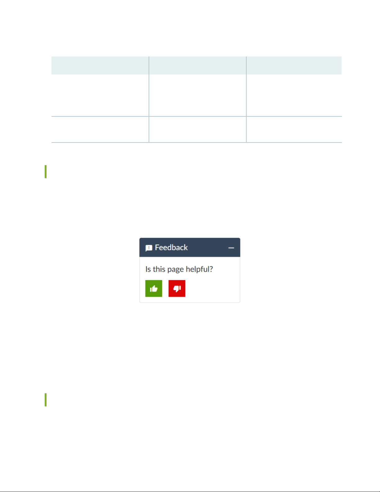
Table 2: Text and Syntax Conventions (continued)
xvi
ExamplesDescriptionConvention
Bold text like this
> (bold right angle bracket)
Represents graphical user interface
(GUI) items you click or select.
Separates levels in a hierarchy of
menu selections.
In the Logical Interfaces box, select
•
All Interfaces.
To cancel the configuration, click
•
Cancel.
In the configuration editor hierarchy,
select Protocols>Ospf.
Documentation Feedback
We encourage you to provide feedback so that we can improve our documentation. You can use either
of the following methods:
Online feedback system—Click TechLibrary Feedback, on the lower right of any page on the Juniper
•
Networks TechLibrary site, and do one of the following:
Click the thumbs-up icon if the information on the page was helpful to you.
•
Click the thumbs-down icon if the information on the page was not helpful to you or if you have
•
suggestions for improvement, and use the pop-up form to provide feedback.
E-mail—Send your comments to techpubs-comments@juniper.net. Include the document or topic name,
•
URL or page number, and software version (if applicable).
Requesting Technical Support
Technical product support is available through the Juniper Networks Technical Assistance Center (JTAC).
If you are a customer with an active Juniper Care or Partner Support Services support contract, or are
Page 17

covered under warranty, and need post-sales technical support, you can access our tools and resources
online or open a case with JTAC.
JTAC policies—For a complete understanding of our JTAC procedures and policies, review the JTAC User
•
Guide located at https://www.juniper.net/us/en/local/pdf/resource-guides/7100059-en.pdf.
Product warranties—For product warranty information, visit https://www.juniper.net/support/warranty/.
•
JTAC hours of operation—The JTAC centers have resources available 24 hours a day, 7 days a week,
•
365 days a year.
Self-Help Online Tools and Resources
For quick and easy problem resolution, Juniper Networks has designed an online self-service portal called
the Customer Support Center (CSC) that provides you with the following features:
Find CSC offerings: https://www.juniper.net/customers/support/
•
Search for known bugs: https://prsearch.juniper.net/
•
xvii
Find product documentation: https://www.juniper.net/documentation/
•
Find solutions and answer questions using our Knowledge Base: https://kb.juniper.net/
•
Download the latest versions of software and review release notes:
•
https://www.juniper.net/customers/csc/software/
Search technical bulletins for relevant hardware and software notifications:
•
https://kb.juniper.net/InfoCenter/
Join and participate in the Juniper Networks Community Forum:
•
https://www.juniper.net/company/communities/
Create a service request online: https://myjuniper.juniper.net
•
To verify service entitlement by product serial number, use our Serial Number Entitlement (SNE) Tool:
https://entitlementsearch.juniper.net/entitlementsearch/
Creating a Service Request with JTAC
You can create a service request with JTAC on the Web or by telephone.
Visit https://myjuniper.juniper.net.
•
Call 1-888-314-JTAC (1-888-314-5822 toll-free in the USA, Canada, and Mexico).
•
For international or direct-dial options in countries without toll-free numbers, see
https://support.juniper.net/support/requesting-support/.
Page 18

1
CHAPTER
Overview
MX10003 System Overview | 19
MX10003 Chassis | 25
MX10003 Cooling System | 30
MX10003 AC Power System | 35
MX10003 DC Power System | 41
MX10003 Routing and Control Board | 47
MX10003 Interface Modules | 53
Page 19
MX10003 System Overview
IN THIS SECTION
Benefits of the MX10003 Router | 19
MX10003 Router Hardware Overview | 20
MX10003 Hardware Components and CLI Terminology | 21
MX10003 Component Redundancy | 23
MX10003 Field-Replaceable Units | 24
The Juniper Networks MX10003 Universal Routing Platform is an Ethernet-optimized edge router with
2.4Tb capacity that provide both switching and carrier-class Ethernet routing. The MX10003 router runs
Junos operating system (Junos OS), enabling a wide range of business and residential applications and
services, including high-speed transport and virtual private network (VPN) services, next-generation
broadband multiplay services, and high-volume Internet data center internetworking. Each router provides
full duplex, high-density Ethernet interfaces and high- capacity switching throughput and uses the Junos
Trio chipset for increased scalability of Layer 2/Layer 3 packet forwarding, buffering, and queuing.
19
Benefits of the MX10003 Router
Space-optimized, power-efficient cloud-era routing platform—The MX10003 caters to the edge and
•
Metro Ethernet needs of service providers, mobile operators, multiple-service operators in space- and
power-constrained environments. Delivering 2.4 Tbps of throughput in just three rack units (3 U), the
MX10003 delivers industry-leading port density and performance while consuming just 0.9 watts per
gigabit of throughput.
Integrated high-precision timing—The MX10003 router eliminates the need for external clocks by
•
supporting highly scalable and reliable hardware-based timing including Synchronous Ethernet for
frequency, and Precision Time Protocol (PTP) for frequency and phase synchronization. The router uses
a hybrid mode, combining Synchronous Ethernet and PTP, to achieve a high level of frequency (10 ppb)
and phase (<1.5 uS) accuracy.
Simplified management through Junos Fusion—You can use the MX10003 as aggregation devices in a
•
Junos Fusion Provider Edge deployment, where EX Series and QFX Series switches function as satellite
devices.
Page 20

MX10003 Router Hardware Overview
The MX10003 router contains modular Routing Engines and multiple Packet Forwarding Engines. The
Packet Forwarding Engine has two “pseudo” Flexible PIC Concentrators (FPC 0 and FPC1). The single
Packet Forwarding Engine takes care of both ingress and egress packet forwarding.
The MX10003 is a compact router, three rack units (3U) tall. Several routers can be stacked in a single
floor-to-ceiling rack for increased port density per unit of floor space.
The router provides two dedicated line card slots for Modular Port Concentrators (MPCs). MPCs install
into the line-card slots. The router supports two redundant Routing and Control Board (RCB). The RCB
houses the Routing Engine and Control Board. The router is powered by six dedicated AC/DC power
supply modules. Cooling is handled by four fan modules.
See Table 3 on page 20 for components supported on the router.
Table 3: MX10003 Router Components
DescriptionComponent
20
2MPC
2Routing and Control Board (RCB)
6Power supply module
4Fan module
Starting in Junos OS Release 18.3R1, you can use the Mellanox 10-Gbps pluggable adapter (QSFP+ to
SFP+ adapter or QSA; model number: MAM1Q00A-QSA) to convert four lane-based ports to a single
lane-based SFP+ port. The QSA adapter has the QSFP+ form factor with a receptacle for the SFP+ module.
Use the QSA adapter to convert a 40-Gbps port to a 10-Gbps or a 1-Gbps port. You can configure the
4x10 Gbps ports on the fixed pic (6XQSFPP) and the QSFP28 ports on the non-MACSEC MIC (JNP-MIC1)
in the 1-Gbps mode, when the SFP is plugged in through the QSA adapter.
NOTE:
The interface name prefix must be xe.
•
Rate selectability at PIC level and port level does not support 1-Gbps speed.
•
For the link to come up, you must configure the no-auto-neg statement on the egress interface.
•
Page 21

NOTE: For a complete list of supported optics on MX10003, see MX10003 Transceivers.
SEE ALSO
MX10003 Cooling System Description | 31
MX10003 AC Power System Description | 35
MX10003 Router Physical Specifications | 65
MX10003 Hardware Components and CLI Terminology
The MX10003 router support the components in Table 4 on page 21, listed in alphabetic order.
21
Table 4: MX10003 Router Hardware Components and CLI Terminology
Hardware Model
NumberComponent
JNP10003 [MX10003]MX10003-BaseChassis
Cooling system, including fan modules and air filters
N/AJNP-AIRFLTR-3RUAir filter kit
Fan TrayJNP-FAN-3RUFan module
Power system components
Power supply module
MIC
JNP-PWR1600-AC
•
JNP-PWR1100-DC
•
Without MACsec
•
support: JNP-MIC1
With MACsec support:
•
JNP-MIC1-MACSEC
JNP-PWR1600-AC
•
JNP-PWR1100-DC
•
MIC1
•
MIC1-MACSEC
•
DescriptionCLI Name
“MX10003 Chassis Description”
on page 25
“MX10003 Cooling System
Description” on page 31
“MX10003 AC Power System
Description” on page 35
Multi-Rate Ethernet MIC
LC2103MX10003-LC2103.MPC
“MX10003 MPC (Multi-Rate)” on
page 54
Page 22

Table 4: MX10003 Router Hardware Components and CLI Terminology (continued)
Hardware Model
NumberComponent
DescriptionCLI Name
22
Routing and Control
Board (RCB)
Transceiver
JNP10003-RE1
•
JNP10003-RE1-LT
•
Module Reference.
RE: RE-S-1600x8
•
CB: Control Board
•
“MX10003 Routing and Control
Board (RCB) Description” on
page 47
Hardware Compatibility ToolXcvrSee MX Series Interface
Table 5 on page 22 lists the spare parts and blank panels available for the router.
Table 5: MX10003 Spare Parts and Blank Panels
DescriptionModel Number
MX10003 chassis, spareJNP10003-CHAS
MX10003 fan module, spareJNP-FAN-3RU
MX10003 RE, spareJNP10003-RE1
JNP10003 RE, redundantJNP10003-RE1-R
JNP10003-LC2103
MX10003 MPC, 6 quad small form-factor pluggable plus transceivers
(QSFP+), 1 MIC slot
MX10003 AC power supply moduleJNP-PWR1600-AC
MX10003 AC power supply, 1600 W, redundantJNP-PWR1600-AC-R
MX10003 DC power supply, 1100 WJNP-PWR1100-DC
MX10003 DC power supply, 1100 W, redundantJNP-PWR1100-DC-R
MX10003 air filter assemblyJNP-FLTRDR-3RU
MX10003 air filterJNP-AIRFLTR-3RU
MX10003 RE blank cover panelJNP-RE-BLNK-3
MX10003 power blank cover panelJNP-PWR-BLNK-3
MX10003 LC2103 blank cover panelJNP-LC-BLNK-3
Page 23

Table 5: MX10003 Spare Parts and Blank Panels (continued)
DescriptionModel Number
MX10003 MIC1 blank cover panelJNP-MIC-BLNK-3
MX10003 Component Redundancy
A fully configured router is designed so that no single point of failure can cause the entire system to fail.
Only a fully configured router provides complete redundancy. All other configurations provide partial
redundancy. The following major hardware components are redundant:
Host subsystem—The host subsystem consists of two Routing and Control Boards (RCBs). The RCB is
•
an integrated board and a single FRU that provides Routing Engine and Control Board functionality. The
router can have one or two host subsystems. If two host subsystems are installed, one functions as the
primary and the other functions as the backup. If the primary host subsystem (or either of its components)
fails, the backup can take over as the primary. The RCB installed in slot 0 functions as the default primary.
23
Power supplies—The router supports six power supplies. Table 6 on page 23 shows the power redundancy
•
supported on the AC and DC powered router for minimum operation. Minimum power supplies required
for non-redundant operation is 2 for AC (high), 3 for DC, and 4 for AC (low). With additional power
supplies, it provides N+1 and N+N redundancy for the system. Both AC and DC systems can withstand
the failure of a single power supply without system interruption in N+1 redundancy mode. If one power
supply fails in a fully redundant system, the other power supply can provide full power to the router
indefinitely.
Table 6: Power Supply Redundancy
Feed RedundancyPSM RedundancyPower Supply
2+22+1AC (250 V; high)
Not allowed4+1AC (110 V; low)
3+33+1DC
Cooling system—The cooling system has a total of four fan modules, which are controlled and monitored
•
by the host subsystem. A fully configured router needs all the four fan modules to operate normal. The
fan modules are at the rear and are used to cool the router. If a fan fails or the temperature rises above
the temperature threshold, the speed of the remaining fans is automatically adjusted to keep the
temperature within the acceptable range.
Page 24

CAUTION: For a fully configured router, all the four fan modules must be operational,
and in the event of any fan module failure the failed fan module must be replaced
immediately.
SEE ALSO
Locating the Serial Number on a MX10003 Router or Component | 169
Guidelines for Packing Hardware Components for Shipment | 174
How to Return a Hardware Component to Juniper Networks, Inc.
MX10003 Field-Replaceable Units
24
Field-replaceable units (FRUs) are router components that can be replaced at the customer site (see
Table 7 on page 24). Replacing most FRUs requires minimal router downtime. The router uses the following
types of FRUs:
Hot-removable and hot-insertable FRUs—You can remove and replace these components without
•
powering off the router or disrupting the routing functions.
Hot-pluggable FRUs—You can remove and replace these components without powering off the router,
•
but the routing functions of the system are interrupted when the component is removed.
Table 7 on page 24 lists the FRUs for the router.
Table 7: Field-Replaceable Units
Hot-Pluggable FRUsHot-Removable and Hot-Insertable FRUs
Backup RCB (if redundant)
•
Primary RCB (if nonstop active routing is
•
configured)
Modular Port Concentrators (MPCs)
•
Modular Interface Cards (MICs)
•
NOTE: MIC installed in MPC slot 1.
Routing and Control Boards
•
(RCB) (nonredundant)
Primary RCB (if nonstop active
•
routing is not configured)
Power supply modules (if redundant)
•
Fan modules (if redundant)
•
Air filter unit
•
Page 25

SEE ALSO
Replacing an MX10003 DC Power Supply | 131
Replacing an MX10003 AC Power Supply | 128
Replacing the MX10003 Air Filter Unit | 118
Replacing an MX10003 Fan Module | 124
Replacing an MX10003 MIC | 142
Replacing an MX10003 MPC | 149
MX10003 Chassis
IN THIS SECTION
25
MX10003 Chassis Description | 25
MX10003 Front and Rear Panel Components | 27
MX10003 Cable Management Bracket Description | 28
Alarm LEDs on the MX10003 Front Panel | 29
MX10003 Chassis Description
The router chassis is a rigid sheet metal structure that houses all the other router components.
Figure 1 on page 26 shows the front of the fully configured chassis. The chassis measures 5.21 in. (13.23 cm)
high, 17.6 in. (44.7 cm) wide, and 30 in. (76.2 cm) deep. The chassis installs in standard 800-mm or 900-mm
deep open rack, 19-in. equipment racks, or telco open-frame racks. The total weight of a fully loaded
router: up to 157.4 lb (71.4 kg) for an AC-powered chassis, and up to 163.4 lb (74.1 kg) for a DC-powered
chassis. For more information, see “MX10003 Router Physical Specifications” on page 65.
Page 26
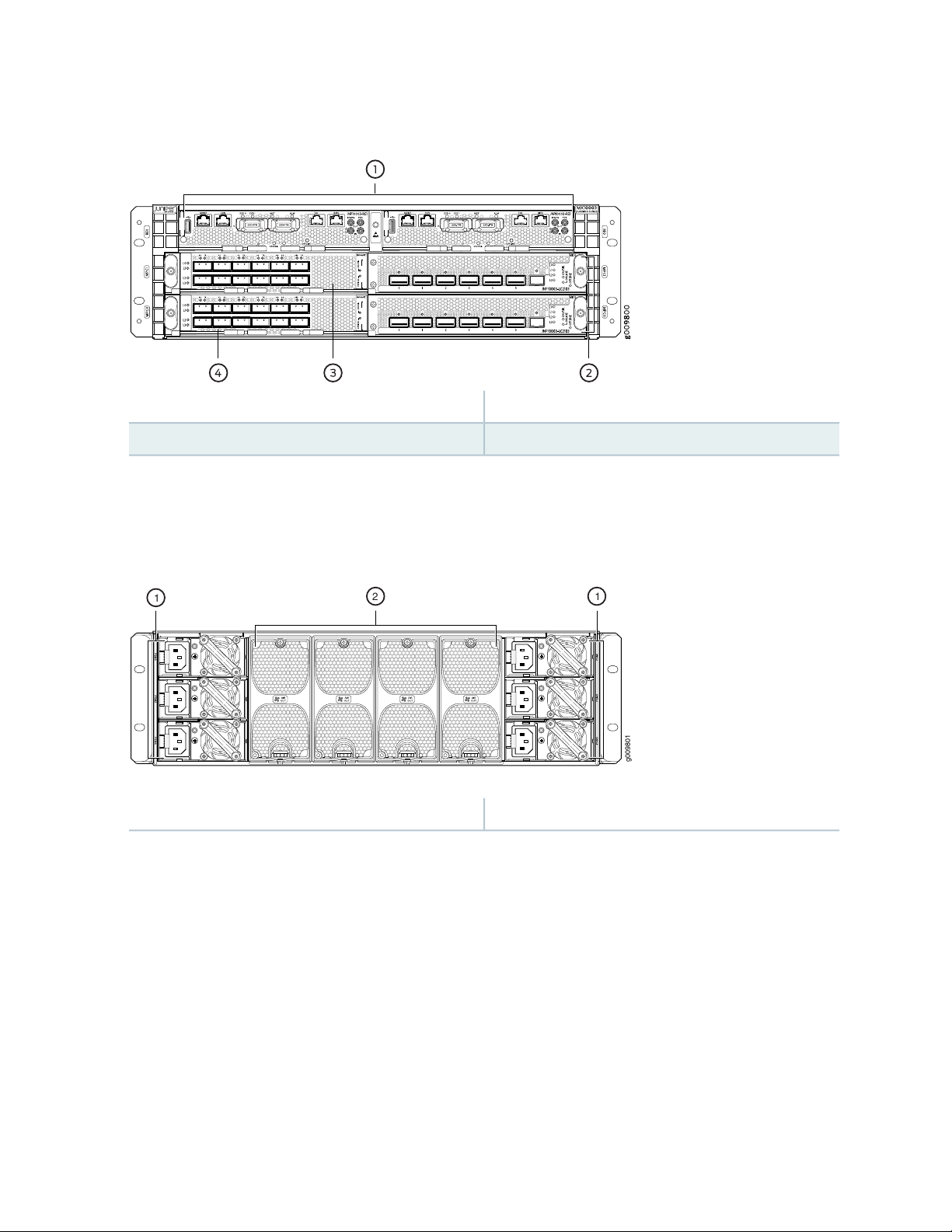
Figure 1: Front View of the MX10003 Router
g009801
2 1
1
3—1— MIC installed in MIC1 slot of MPC1Routing and Control Boards (RCBs)
4—2— MIC installed in MIC1 slot of MPC0MPCs
The router comes in two variants–AC-powered and DC-powered. Figure 2 on page 26 and
Figure 3 on page 27 shows the rear of the fully configured chassis.
26
Figure 2: Rear View of the AC-Powered MX10003 Router
2—1— Fan modulesPower supply modules (AC)
Page 27

Figure 3: Rear View of the DC-Powered MX10003 Router
2—1— Fan modulesPower supply modules (DC)
Figure 4 on page 27 shows the electrostatic discharge (ESD) point on the router.
CAUTION: Before removing or installing components, attach an ESD strap to an ESD
point, and place the other end of the strap around your bare wrist. Failure to use an
ESD strap could result in damage to the hardware components.
27
Figure 4: ESD Point on the MX10003 Router
1—ESD point
MX10003 Front and Rear Panel Components
The front panel on the front of the router enables you to view status and troubleshooting information at
a glance. The front panel contains LEDs for the router components, online/offline and reset buttons,
auxiliary and console ports, clocking ports, and ports for the 10-Gigabit Ethernet MIC.
Page 28

Front Panel Components
Table 8 on page 28 lists the components on the front panel of the MX10003 router.
Table 8: Front Panel Components in a Fully Configured MX10003 Router
28
Number of FRUsSlotsComponent
20 and 1RCB
20 and 1MPC
MIC (installed in MPC)
NOTE: MIC installs in slot 1 of the MPC.
Rear Panel Components
Table 9 on page 28 lists the components on the rear panel of the MX10003 router.
Table 9: Rear Panel Components in a Fully Configured MX10003 Router
Number of FRUsSlotsComponent
60 through 5Power supply module
40 through 3Fan module
11 per MPC
2-Cable management brackets
1-Air filter unit
MX10003 Cable Management Bracket Description
The cable management bracket (see Figure 5 on page 29) consists of dividers and installs on the front of
the chassis. The cable management bracket enables you to route the cables outside the router and away
from the RCBs, MICs, and MPCs.
Page 29

Figure 5: Cable Management Bracket
The air filter unit is installed on the cable management brackets. Before installing the air filter unit, ensure
that the cable management brackets are already installed on the front of the router. Figure 6 on page 29
shows the air filter unit along with the cable management brackets installed on the router.
Figure 6: Cable Management Brackets and Air Filter Unit Installed on the Router
29
SEE ALSO
Replacing the MX10003 Air Filter Unit | 118
Installing the MX10003 Router in a Rack | 90
Alarm LEDs on the MX10003 Front Panel
One alarm LED located on the front panel of the RCB. A red light indicates a critical condition that can
result in a system shutdown, and a yellow light indicates a less severe condition that requires monitoring
or maintenance.
Table 10 on page 30 describes the alarm LED in more detail.
Page 30
NOTE: Only the primary RCB drives the LED to show the status of the chassis.
Table 10: Alarm LEDs on the MX10003 Front Panel
DescriptionColorShape
30
Red
Yellow
Critical alarm LED—Indicates a critical condition
that can cause the router to stop functioning.
Possible causes include component removal,
failure, or overheating.
Warning alarm LED—Indicates a serious but
nonfatal error condition, such as a maintenance
alert or a significant increase in component
temperature.
SEE ALSO
Routine Maintenance Procedures for MX10003 Routers | 117
MX10003 Cooling System
IN THIS SECTION
MX10003 Cooling System Description | 31
MX10003 Fan Module LED | 34
Page 31

MX10003 Cooling System Description
IN THIS SECTION
Fan Modules | 31
Airflow | 33
Air Filter Unit | 33
Power Supply Cooling System | 34
The cooling system components work together to keep all router components within the acceptable
temperature range.
The cooling system consists of the following components:
31
Fan Modules
The chassis monitors the temperature of the router components. When the router is operating normally,
the fans function at lower than full speed. If a fan fails or the ambient temperature rises above a threshold,
the speed of the remaining fans is automatically adjusted to keep the temperature within the acceptable
range. If the ambient maximum temperature specification is exceeded and the system cannot be adequately
cooled, the Routing Engine shuts down the router by disabling output power from each power supply.
The router has four fan modules that install vertically at the rear of the router. Each fan module contains
two counter-rotating fans. The fan modules are hot-insertable and hot-removable field-replaceable units
(FRUs) (see Figure 7 on page 32).
Page 32

Figure 7: Fan Module
g0 0 9828
1
2
3
32
3—1— Status LEDCaptive screw
2—Latch
Page 33

Airflow
The router has front-to-back (AIR OUT) cooling system (see Figure 8 on page 33). Air is pulled through
the front the chassis toward the fan module, which exhausts the air out of the router.
Figure 8: Airflow Through the Router
33
Air Filter Unit
The air filter unit consists of three parts–the outer filter cover, the air filter, and the inner cage that form
the body, and the air filter (see Figure 9 on page 33). The air filter sits right inside the outer filter cover
and the inner cage. The air filter unit is installed into the cable management brackets, and are held tightly
by captive screws.
Figure 9: Air Filter Unit
2—Air filter
3—1— Inner cageOuter filter cover
Page 34

Power Supply Cooling System
The power supplies are self-cooling and are located in the rear of the router (to the left and the right of
the rear of the chassis). The exhaust for the power supplies are also located on the rear of the chassis.
SEE ALSO
Replacing the MX10003 Air Filter Unit | 118
Replacing the MX10003 Air Filter | 120
MX10003 Fan Module LED
Each fan module contains one bicolor LED. “MX10003 Cooling System Description” on page 31 shows
the fan module LED.
34
Table 11 on page 34 describes the behavior of the fan module LEDs.
Table 11: Fan Module LEDs
DescriptionStateColorLabel
BlinkingGreenSTATUS
steadily
Red
steadily
Fan module hardware initialization complete and software
initialization pending.
Software initialization complete and the fan is functioning normally.On
Faulty and not functioning normallyOn
SEE ALSO
Replacing an MX10003 Fan Module | 124
Page 35

MX10003 AC Power System
IN THIS SECTION
MX10003 AC Power System Description | 35
MX10003 AC Power Supply Module LEDs | 36
MX10003 Router AC Power Specifications | 37
AC Power Circuit Breaker Requirements for the MX10003 Router | 38
AC Power Cord Specifications for MX10003 Routers | 39
MX10003 AC Power System Description
35
The MX10003 uses either AC or DC power supply modules (see Figure 10 on page 36 ). The router contain
six power supplies located at the rear of the chassis in slots PSM0 through PSM5. The AC or DC power
supplies directly plug into the midplane and are placed symmetrically on both sides of the chassis for better
thermal management. Each power supply has a handle, an ejection lever, and a status LED. The power
supplies connect to the baseboard, which distributes the different output voltages produced by the power
supplies to the router components, depending on their voltage requirements. A minimum of 3 power
supplies are required for non-redundant operation. If one power supply in a redundant configuration fails
or is removed, the remaining power supplies assume the entire electrical load without interruption. See
“MX10003 Component Redundancy” on page 23 for more information on power redundancy supported
on the AC and DC powered router. Each power supply is cooled by its own internal cooling system. The
chassis is designed to support N+N mode with feed redundancy, and N+1 mode without feed redundancy.
Redundant power supplies are hot-removable and hot-insertable. When you remove a power supply from
a router that uses only one power supply, the router might shut down depending on your configuration.
CAUTION: Do not mix AC and DC power supplies in the same chassis.
NOTE: Routers configured with only one power supply are shipped with a blank panel installed
over the power supply slot that is not populated.
Page 36

Each AC power supply weighs approximately 3.4 lb (1.54 kg) and consists of a handle, an ejector lever, an
g009807
AC appliance inlet, a fan, and an LED to monitor the status of the power supply. Figure 10 on page 36
shows the power supply.
Each inlet requires a dedicated AC power feed and a dedicated customer-site circuit breaker. We recommend
that you use a minimum 15-A (110 VAC) customer-site circuit breaker, or as required by local code.
WARNING: The router is a pluggable type A equipment installed in a restricted-access
location. It has a separate protective earthing terminal (sized for M4 hex screws)
provided on the chassis in addition to the grounding pin of the power supply cord. This
separate protective earthing terminal must be permanently connected to earth.
Figure 10: AC Power Supply
36
MX10003 AC Power Supply Module LEDs
Figure 11 on page 37 shows the AC power supplies components along with the status LED.
Page 37

Figure 11: AC Power Supplies Components
g0 0 9806
1 2 3 4
SEE ALSO
37
3—1— Status LEDEjector lever
4—2— HandleAC inlet plug
Routine Maintenance Procedures for MX10003 Routers | 117
MX10003 Router AC Power Specifications
Table 12 on page 37 lists the AC power system electrical specifications.
Table 12: AC Power System Electrical Specifications
SpecificationItem
AC input voltage
Operating range:
AC low: 90 through 140 VAC
AC high: 180 through 264 VAC
50 through 60 Hz (nominal)AC input line frequency
25 AAC system current rating
Table 13 on page 38 lists the AC power supply electrical specifications.
2500 WAC system input power
Page 38

Table 13: AC Power Supply Electrical Specifications
SpecificationItem
38
Maximum output power
AC input voltage
AC high: 1600 W
AC low: 800 W
Operating range:
90 through 140 VAC: 800 W
180 through 264 VAC: 1600 W
50 through 60 Hz (nominal)AC input line frequency
10 A @ 100 VAC through 240 VACAC input current rating
SEE ALSO
Routine Maintenance Procedures for MX10003 Routers | 117
Replacing an MX10003 AC Power Supply | 128
General Safety Guidelines and Warnings | 181
General Electrical Safety Guidelines and Warnings | 210
Prevention of Electrostatic Discharge Damage | 186
AC Power Circuit Breaker Requirements for the MX10003 Router
We recommend that you use a dedicated customer-site circuit breaker rated for 15 A (110 VAC) minimum
or 10 A (220 VAC) minimum for each AC power feed, or as required by local code. Doing so enables you
to operate the router in any configuration without upgrading the power infrastructure.
SEE ALSO
Routine Maintenance Procedures for MX10003 Routers | 117
Replacing an MX10003 AC Power Supply | 128
Calculating Power Requirements for MX10003 Router | 71
General Safety Guidelines and Warnings | 181
Page 39

General Electrical Safety Guidelines and Warnings | 210
Prevention of Electrostatic Discharge Damage | 186
AC Power Cord Specifications for MX10003 Routers
A detachable AC power cord is supplied with the AC power supplies. The coupler is type C13 as described
by International Electrotechnical Commission (IEC) standard 60320. The plug end of the power cord fits
into the power source outlet that is standard for your geographical location.
CAUTION: The AC power cord provided with each power supply is intended for use
with that power supply only and not for any other use.
39
NOTE: In North America, AC power cords must not exceed 4.5 meters in length, to comply with
National Electrical Code (NEC) Sections 400-8 (NFPA 75, 5-2.2) and 210-52 and Canadian
Electrical Code (CEC) Section 4-010(3). The cords supplied with the switch are in compliance.
Table 14 on page 39 gives the AC power cord specifications for the countries and regions listed in the
table.
Table 14: AC Power Cord Specifications
Juniper Model NumberPlug StandardsElectrical SpecificationsCountry/Region
CBL-EX-PWR-C13-ARIRAM 2073 Type RA/3250 VAC, 10 A, 50 HzArgentina
250 VAC, 10 A, 50 HzAustralia
SAA/3
CBL-EX-PWR-C13-AUAS/NZZS 3112 Type
CBL-EX-PWR-C13-BRNBR 14136 Type BR/3250 VAC, 10 A, 50 HzBrazil
CBL-EX-PWR-C13-CHGB 1002-1996 Type PRC/3250 VAC, 10 A, 50 HzChina
Switzerland, and United
Kingdom)
CBL-EX-PWR-C13-EUCEE (7) VII Type VIIG250 VAC, 10 A, 50 HzEurope (except Italy,
CBL-EX-PWR-C13-INIS 1293 Type IND/3250 VAC, 10 A, 50 HzIndia
CBL-EX-PWR-C13-ILSI 32/1971 Type IL/3G250 VAC, 10 A, 50 HzIsrael
Page 40

Table 14: AC Power Cord Specifications (continued)
40
Juniper Model NumberPlug StandardsElectrical SpecificationsCountry/Region
CBL-EX-PWR-C13-ITCEI 23-16 Type I/3G250 VAC, 10 A, 50 HzItaly
Japan
Hz
Korea
Hz
250 VAC, 10 A, 50 HzSouth Africa
ZA/13
Taiwan
50 Hz
CBL-EX-PWR-C13-JPSS-00259 Type VCTF125 VAC, 12 A, 50 Hz or 60
CBL-EX-PWR-C13-KRCEE (7) VII Type VIIGK250 VAC, 10 A, 50 Hz or 60
CBL-EX-PWR-C13-USNEMA 5-15 Type N5-15125 VAC, 13 A, 60 HzNorth America
CBL-EX-PWR-C13-SASABS 164/1:1992 Type
CBL-EX-PWR-C13-SZSEV 6534-2 Type 12G250 VAC, 10 A, 50 HzSwitzerland
CBL-EX-PWR-C13-TWNEMA 5-15P Type N5-15P125 VAC, 11 A and 15 A,
CBL-EX-PWR-C13-UKBS 1363/A Type BS89/13250 VAC, 10 A, 50 HzUnited Kingdom
Figure 12 on page 40 illustrates the plug on the power cord for some of the countries or regions listed in
Table 14 on page 39.
Figure 12: AC Plug Types
SEE ALSO
General Safety Guidelines and Warnings | 181
General Electrical Safety Guidelines and Warnings | 210
Prevention of Electrostatic Discharge Damage | 186
Page 41

MX10003 DC Power System
IN THIS SECTION
MX10003 DC Power System Description | 41
MX10003 DC Power Supply Module LEDs | 42
MX10003 Router DC Power Specifications | 43
DC Power Circuit Breaker Requirements for the MX10003 Router | 44
DC Power Source Cabling for MX10003 Router | 44
DC Power Cable Specifications for MX10003 Router | 45
41
MX10003 DC Power System Description
The MX10003 uses either AC or DC power supply modules (see Figure 13 on page 42). The router contain
six power supplies located at the rear of the chassis in slots PSM0 through PSM5. The AC or DC power
supplies directly plug into the midplane and are placed symmetrically on both sides of the chassis for better
thermal management. Each power supply has a handle, an ejection lever, and a status LED. The power
supplies connect to the baseboard, which distributes the different output voltages produced by the power
supplies to the router components, depending on their voltage requirements. A minimum of 3 power
supplies are required for non-redundant operation. If one power supply in a redundant configuration fails
or is removed, the remaining power supplies assume the entire electrical load without interruption. See
“MX10003 Component Redundancy” on page 23 for more information on power redundancy supported
on the AC and DC powered router. Each power supply is cooled by its own internal cooling system. The
chassis is designed to support N+N mode with feed redundancy, and N+1 mode without feed redundancy.
Redundant power supplies are hot-removable and hot-insertable. When you remove a power supply from
a router that uses only one power supply, the router might shut down depending on your configuration.
CAUTION: Do not mix AC and DC power supplies in the same chassis.
NOTE: Routers configured with only one power supply are shipped with a blank panel installed
over the power supply slot that is not populated.
Page 42

Each DC power supply weighs approximately 4.4 lb (1.99 kg) and consists of a handle, an ejector lever, a
g0 0 9811
21 3 4
status LED, and a terminal block that provides a single DC input (–48 VDC and return) that requires a
dedicated customer-site circuit breaker. We recommend that you use a dedicated customer-site circuit
breaker rated for 40 A (–48 VDC) minimum, or as required by local code.
Figure 13 on page 42 shows the power supply.
Figure 13: DC Power Supply
42
MX10003 DC Power Supply Module LEDs
Figure 14 on page 42 shows the DC power supplies components along with the status LED.
Figure 14: DC Power Supplies Components
3—1— DC inlet cable lug pointEjector lever
4—2— HandleStatus LED
Page 43

MX10003 Router DC Power Specifications
Table 15 on page 43 lists the DC power system electrical specifications.
Table 15: DC Power System Electrical Specifications
SpecificationItem
Operating range: –40 through –72 VDCDC input voltage
54 A @ –48 VDC (maximum)DC system input current
rating
2500 WDC system input power
Table 16 on page 43 lists the DC power supply electrical specifications.
Table 16: DC Power Supply Electrical Specifications
43
SpecificationItem
1100 WMaximum output power
DC input voltage
Minimum: –40 VDC
Nominal: –48 VDC, –60 VDC
Operating range: –40 through –72 VDC
32 A @ –48 VDCDC input current rating
SEE ALSO
Routine Maintenance Procedures for MX10003 Routers | 117
Replacing an MX10003 DC Power Supply | 131
MX10003 Power Planning | 71
General Safety Guidelines and Warnings | 181
General Electrical Safety Guidelines and Warnings | 210
Prevention of Electrostatic Discharge Damage | 186
Page 44

DC Power Circuit Breaker Requirements for the MX10003 Router
Each DC power supply has a single DC input (–48 VDC and return) that requires a dedicated circuit breaker.
We recommend that you use a dedicated customer-site circuit breaker rated for 40 A (–48 VDC) minimum,
or as required by local code. Doing so enables you to operate the router in any configuration without
upgrading the power infrastructure.
If you plan to operate a DC-powered router at less than the maximum configuration and do not provision
a 40 A (–48 VDC) circuit breaker, we recommend that you provision a dedicated customer-site circuit
breaker for each DC power supply rated for at least 125 percent of the continuous current that the system
draws at –48 VDC.
SEE ALSO
Routine Maintenance Procedures for MX10003 Routers | 117
Replacing an MX10003 DC Power Supply | 131
44
MX10003 Power Planning | 71
General Safety Guidelines and Warnings | 181
General Electrical Safety Guidelines and Warnings | 210
Prevention of Electrostatic Discharge Damage | 186
DC Power Source Cabling for MX10003 Router
The DC power supply in PS0 must be powered by a dedicated power feed derived from feed A, and the
DC power supply in PS1 must be powered by a dedicated power feed derived from feed B. This configuration
provides the commonly deployed A/B feed redundancy for the system.
CAUTION: You must ensure that power connections maintain the proper polarity.
The power source cables might be labeled (+) and (–) to indicate their polarity. There
is no standard color coding for DC power cables. The color coding used by the external
DC power source at your site determines the color coding for the leads on the power
cables that attach to the terminal studs on each power supply.
Page 45

WARNING: For field-wiring connections, use copper conductors only.
CAUTION: Power cords and cables must not block access to device components or
drape where people could trip on them.
SEE ALSO
Routine Maintenance Procedures for MX10003 Routers | 117
Replacing an MX10003 DC Power Supply | 131
MX10003 Power Planning | 71
45
General Safety Guidelines and Warnings | 181
General Electrical Safety Guidelines and Warnings | 210
Prevention of Electrostatic Discharge Damage | 186
DC Power Cable Specifications for MX10003 Router
IN THIS SECTION
DC Power Cable Lug Specifications | 45
DC Power Cable Specifications | 46
DC Power Cable Lug Specifications
The accessory box shipped with the router includes the cable lugs that attach to the terminal of each
power supply.
Page 46

Figure 15: DC Power Cable Lug
CAUTION: Before router installation begins, a licensed electrician must attach a cable
lug to the grounding and power cables that you supply. A cable with an incorrectly
attached lug can damage the router.
46
DC Power Cable Specifications
You must supply four DC power cables that meet the following specifications: 10-AWG (1.3 mm2), minimum
60° C wire, or as required by the local code.
SEE ALSO
Routine Maintenance Procedures for MX10003 Routers | 117
Replacing an MX10003 DC Power Supply | 131
MX10003 Power Planning | 71
General Safety Guidelines and Warnings | 181
General Electrical Safety Guidelines and Warnings | 210
Prevention of Electrostatic Discharge Damage | 186
Page 47

MX10003 Routing and Control Board
IN THIS SECTION
MX10003 Routing and Control Board (RCB) Description | 47
MX10003 RCB LEDs | 52
MX10003 Routing and Control Board (RCB) Description
IN THIS SECTION
47
Routing and Control Board Functions | 48
Routing and Control Board Components | 48
RCB Front Panel | 48
RCB Interface Ports | 50
The host subsystem provides routing protocol processes, as well as software processes that control the
router’s interface, the chassis components, system management, and user access to the router. These
routing processes run on top of a kernel that interacts with the Packet Forwarding Engine. The MX10003
host subsystem consists of two Routing and Control Boards, or RCBs. The RCB is an integrated board and
a single FRU that provides Routing Engine (RE) and Control Board (CB) functionality. The RE performs all
route-processing functions, whereas the CB performs chassis control and management plane functionality.
The RCB provides control plane functions. You can install one or two RCBs on the router. Each RCB
functions as a unit.
NOTE: Install two RCBs for redundant protection. If you install only one RCB, you can install it
in slot 0 or slot 1. By default, slot 0 functions as the primary.
Page 48

CAUTION: If one of the RCBs fails, do not remove the failed RCB until you have a
replacement or blank panel to install.
The MX10003 router supports the following RCBs:
JNP10003-RE1
•
JNP10003-RE1-LT
•
This topic covers:
Routing and Control Board Functions
The Routing and Control Board integrates the Routing Engine and Control Board functions into a single
management unit. Each RCB provides all the functions needed to manage the operation of the modular
chassis:
48
System control functions such as environmental monitoring
•
Routing Layer 2 and Layer 3 protocols
•
Communication to all components such as line cards, power, and cooling
•
Transparent clocking
•
Alarm and logging functions
•
Routing and Control Board Components
Each RCB consists of the following internal components:
High-performance 1.6-GHz Intel 8 Core X86 CPU
•
64-GB DDR4 RAM
•
100-GB SATA SSD
•
RCB Front Panel
Figure 16 on page 49 shows the front panel of the MX10003 RCB (model number: JNP10003-RE1).
Page 49

Figure 16: JNP10003-RE1 RCB Ports
g009824
1 2 3 4 5 6 7 8 9 10
11121314
49
USB port
8—1— Time of day (ToD) port with LEDs (This port is
reserved for future use)
9—2— BITS port with LEDsManagement (MGMT) port
10—3— Clocking portsConsole (CON) port
11—4— OFFLINE buttonSSD LEDs
12—5— ONLINE LEDSSD slots (0 and 1)
13—6— OK/FAIL LEDPrimary (MST) LED
14—7— RESET buttonAlarm (ALM) LED
Figure 17 on page 50 shows the front panel of the MX10003 RCB with limited encryption support (model
number: JNP10003-RE1-LT).
Page 50

Figure 17: JNP10003-RE1-LT RCB Ports
g100093
1 2 3 4 5 6 7 8 9
1011121314
JNP10003-RE1-LT
50
USB port
8—1— Time of day (ToD) port with LEDs (This port is
reserved for future use)
9—2— BITS port with LEDsManagement (MGMT) port
10—3— Clocking portsConsole (CON) port
11—4— OFFLINE buttonSSD LEDs
12—5— ONLINE LEDSSD slots (0 and 1)
13—6— OK/FAIL LEDPrimary (MST) LED
14—7— RESET buttonAlarm (ALM) LED
The MX10003 router with JNP10003-RE1-LT RCB supports only Junos Limited image. The Junos Limited
image does not have data-plane encryption and is intended only for countries in the Eurasian Customs
Union because these countries have import restrictions on software containing data-plane encryption.
Unlike the Junos Worldwide image, the Junos Limited image supports control plane encryption through
Secure Shell (SSH) and Secure Sockets Layer (SSL), thus allowing secure management of the system. The
Limited Restriction RCB boots only the encryption free Junos software and fails to boot if the fully encrypted
Junos software is used for booting. The Junos upgrade and VMHost upgrade using non-limited version of
Junos software fails on the JNP10003-RE1-LT RCB.
The command show chassis hardware [models | clei-models | extensive] displays the model number and
helps identifying the different SKUs. An alarm, Mixed Master and Backup RE types is displayed when
dissimilar Routing Engines are present on the chassis (see Chassis Alarms).
RCB Interface Ports
The ports located on the RCB, connect the RCB to one or more external devices on which system
administrators can issue Junos OS CLI commands to manage the router. In addition, ports to connect
external clock interfaces for BITS and GPS function are also available on the RCB.
The RCB interface ports with the indicated labels function are as follows (see Figure 16 on page 49):
Page 51

CON—Connects the RCB to a system console through a serial cable with an RJ-45 connector.
•
MGMT—Connects the RCB through an Ethernet connection to a management LAN (or any other device
•
that plugs into an Ethernet connection) for out-of-band management. The port uses an autosensing
RJ-45 connector to support 10-Mbps, 100-Mbps, or 1000-Mbps connections. Two small LEDs (an activity
LED and a link LED) on the port indicate the connection in use.
The link LED is:
lit amber (steady) when the 1000-Mbps link is up.
•
lit green (steady) when the 100-Mbps link is up.
•
off when the 10-Mbps link is up.
•
The activity LED is:
lit green (blinking) when traffic is passing through the port.
•
lit green (steady) when traffic is not passing through the port.
•
Both activity and link LEDs are off when the link is down.
51
BITS—Building-integrated timing supply (BITS) external clocking interface for connection to external
•
clocking devices.
ToD—Time-of-day (TOD) port on the front panel of the router allows you to connect external timing
•
signal sources.
NOTE: This port is reserved for future use.
10MHZ (one input and one output)—The 10-MHz timing connectors on the front panel of the router
•
connect to external clock signal sources. The clocking ports provide the synchronized output clocks from
any one of the reference clock inputs based on the clock’s priority.
PPS (one input and one output)—1-pulse-per-second (PPS) connectors on the front panel of the router
•
connect to external clock signal sources. The clocking ports provide the synchronized output clocks from
any one of the reference clock inputs based on the clock’s priority.
USB—Provides a removable media interface through which you can install Junos OS manually. Junos
•
OS supports USB version 1.0 and later.
SEE ALSO
Replacing an MX10003 RCB | 137
RJ-45 Connector Pinouts for MX Series CB-RE or RCB Auxillary and Console Ports | 80
Page 52

RJ-45 Connector Pinouts for an MX Series CB-RE or RCB Management Port | 81
MX10003 RCB LEDs
The Routing and Control Board (RCB) is an integrated board and a single FRU that provides Routing Engine
and Control Board functionality.
The LEDs—labeled ONLINE, MST, OK/FAIL, LINK, GPS, BITS—are located directly on the faceplate of the
RCB. Table 17 on page 52 describes the functions of the Routing Engine interface of the RCB.
NOTE: The functioning of the MX10003 router is contolled by the RCB, and the LEDs present
on the RCBs displays the status and functioning of the MX10003 chassis.
Table 17: MX10003 RCB LEDs
52
BlueMST
YellowOK/FAIL
Green
On
steadily
steadily
steadily
steadily
DescriptionStateColorLabel
RCB is starting Junos OS.BlinkingGreenONLINE
RCB is starting Linux.BlinkingYellow
Both Junos OS and Linux are successfully loaded
on the RCB.
RCB is offline.Off
RCB is the primary.On
RCB is the backup.Off–
RCB has failed.On
RCB is functioning normally.On
SSD0 is active.BlinkingGreenSSD0
SSD1 is active.BlinkingGreenSSD1
Page 53

Table 17: MX10003 RCB LEDs (continued)
DescriptionStateColorLabel
53
GreenBITS
Red
On
steadily
steadily
SEE ALSO
Replacing an MX10003 RCB | 137
RELATED DOCUMENTATION
Routing Engine Specifications
Supported Routing Engines by Router
Building-integrated timing supply (BITS) external
clocking interface is active.
BITS external clocking interface has failed.On
BITS external clocking interface is offline.Off–
MX10003 Interface Modules
IN THIS SECTION
MX10003 MPC (Multi-Rate) | 54
MX10003 Port and Interface Numbering | 56
MX10003 MPC (Multi-Rate) LEDs | 56
Multi-Rate Ethernet MIC LEDs | 57
Page 54

MX10003 MPC (Multi-Rate)
Junos OS release 17.3R1 and laterSoftware release
•
54
Description
Hardware features
Software features
Weight: 30 lb (13.61 kg) (net weight without blank panel and without any MIC in slot 1)
•
Model number: MX10003-LC2103
•
Power requirement:
•
715 W at 55° C
660 W at 25° C
Name in the CLI: LC2103
•
The MX10003 MPC is a 1.2-Terabit capable MPC with three Packet Forwarding Engine complexes (that is, three
•
EA ASICs). The EA ASIC operates in 400G mode.
The Packet Forwarding Engine is based on the third generation of the Trio chpiset architecture---namely, the EA
•
(Eagle) ASIC. The Packet Forwarding Engine offers 400 Gbps of WAN and fabric bandwidth each.
MX10003 MPC has six built-in QSFP+ optics ports, and one MIC slot.
•
Supports Multi-Rate Ethernet Modular Interface Card (MIC) (model numbers: JNP-MIC1 and JNP-MIC1-MACSEC),
•
and the fixed-port PIC (6xQSFPP). For information about which MICs are supported on this MPC, see MIC/MPC
Compatibility.
Supports maximum transmission units (MTUs) from 256 bytes through 16,000 bytes for transit traffic, and from
•
256 bytes through 9,500 bytes for host bound packets.
Dynamic Power Management for effective utilization of available power.
•
Inline Active Flow Monitoring for higher scalability and performance.
•
Flexible Queuing Mode to support 32,000 queues per line card, including queues on both ingress and egress interfaces.
•
Supports up to 512,000 queues per slot or 768,000 queues per slot.
Hyper Mode to speed up packet processing.
•
Optical diagnostics and related alarms.
•
Cables and
connectors
For more information about features supported on MX10003 MPC, see Protocols and Applications Supported by the
MX10003 MPC (Multi-Rate) on the MX10003 Router.
TIP: You can use the Hardware Compatibility Tool to find information about the pluggable transceivers supported
on your Juniper Networks device.
The list of supported transceivers for the MX Series is located at
https://pathfinder.juniper.net/hct/category/#catKey=100001&modelType;=All&pf;=MX+Series.
Page 55

55
Power requirements
(without MICs)
LEDs
Table 18 on page 55 summarize the port speed capability of MX10003 MPCs.
Table 18: MX10003 MPC (Multi-Rate) Port Speed
At different temperatures:
•
55° C: 715 W
25° C: 660 W
OK/FAIL LED, one bicolor:
Steady green—MPC is functioning normally and the link is up.
•
Off—MPC is plugged-in but not powered on.
•
Red—MPC has failed.
•
For information on the lane LEDs (Lo, L1, L2, and L3), see MPC and MIC Lane LED Scheme Overview.
Port Speed SupportedPort NumberMIC
0-5PIC 0
40 Gigabit Ethernet
4X10-Gigabit Ethernet
0-11PIC 1
100 Gigabit Ethernet
40 Gigabit Ethernet
4X10-Gigabit Ethernet
SEE ALSO
MPC and MIC Lane LED Scheme Overview
Configuring Port Speed on MX10003 MPC to Enable Different Port Speeds
MX10003 MPC Port Speed Overview
Interface Naming Conventions for MX10003 MPC
Port Speed for Routing Devices
MX Series MPC Overview
MPCs Supported by MX Series Routers
Replacing an MX10003 MIC | 142
Page 56

MX10003 Port and Interface Numbering
In the physical part of the interface name, a hyphen (-) separates the media type from the MPC number
(represented as an FPC in the CLI), and a slash (/) separates the logical PIC and port numbers:
type-fpc/pic/port
type—Media type, which identifies the network device. For example:
•
xe—10-Gigabit Ethernet interface
•
et—100-Gigabit Ethernet interfaces (40 and 100-Gigabit Ethernet interface)
•
For a complete list of media types, see Interface Naming Overview in the MX Series 5G Universal Routing
Platform Interface Module Reference guide.
fpc—Slot in which the MPC is installed, and are represented in the CLI as either FPC 0 or FPC 1.
•
pic—Logical PIC on the MIC. The number of logical PICs varies depending on the type of MIC.
•
port—Port number.
•
56
SEE ALSO
Interface Naming Conventions for MX10003 MPC
MX10003 MPC (Multi-Rate) LEDs
The MX10003 MPC (Multi-Rate) has LEDs located on the front panel.
Table 19 on page 56 describes the link LEDs in more detail.
Table 19: MX10003 MPC (Multi-Rate) LEDs
LED
Status
GreenOK/FAIL
steadily
DescriptionStateColor
MPC is functioning normally and the link is up.On
MPC is plugged-in but not powered on.Off
MPC has failed.-Red
Page 57

Table 19: MX10003 MPC (Multi-Rate) LEDs (continued)
LED
Status
DescriptionStateColor
MPC is online.-GreenONLINE
For information on the lane LEDs (Lo, L1, L2, and L3), see MPC and MIC Lane LED Scheme Overview.
SEE ALSO
MPC and MIC Lane LED Scheme Overview
Configuring Port Speed on MX10003 MPC to Enable Different Port Speeds
MX10003 MPC Port Speed Overview
Port Speed for Routing Devices
57
MICs Supported by MX Series Routers
Interface Naming Conventions for MX10003 MPC
Multi-Rate Ethernet MIC LEDs
For the Multi-Rate MICs supported by MX series routers, see Multi-Rate Ethernet MIC.
The Multi-Rate Ethernet Modular Interface Card (MIC) has link LEDs located on the front panel.
Table 20 on page 57 describes the link LEDs in more detail.
Table 20: Multi-Rate Ethernet MIC LEDs
DescriptionStateColor
Green
steadily
Link is up.On
No link.Off
Like port status LED, each individual lane LED support four states: OFF, AMBER, GREEN, RED. See MPC
and MIC Lane LED Scheme Overview for more details.
SEE ALSO
Page 58

MPC and MIC Lane LED Scheme Overview
Configuring Port Speed on MX10003 MPC to Enable Different Port Speeds
MX10003 MPC Port Speed Overview
Port Speed for Routing Devices
MICs Supported by MX Series Routers
58
Page 59

2
CHAPTER
Site Planning, Preparation, and
Specifications
MX10003 Site Preparation Checklist | 60
MX10003 Site Guidelines and Requirements | 61
MX10003 Power Planning | 71
MX10003 Network Cable and Transceiver Planning | 75
MX10003 Management and Console Port Specifications and Pinouts | 80
Page 60

MX10003 Site Preparation Checklist
The checklist in Table 21 on page 60 summarizes the tasks you must perform when preparing a site for
router installation.
Table 21: MX10003 Site Preparation Checklist
Environment
“MX10003 Router Environmental Specifications” on page 61Verify that environmental factors such as
temperature and humidity do not exceed
router tolerances.
Power
60
grounding.
Measure distance between external power
sources and router installation site.
requirements.
Rack
Select the type of rack or cabinet.
required space clearances.
building structure.
“MX10003 Router Grounding Specifications” on page 62Locate sites for connection of system
“MX10003 Router DC Power Specifications” on page 43
“MX10003 Router AC Power Specifications” on page 37
“Calculating Power Requirements for MX10003 Router” on page 71Calculate the power consumption and
“MX10003 Router Rack Requirements” on page 67
“MX10003 Router Cabinet Requirements and Specifications” on page 69
“MX10003 Router Clearance Requirements for Airflow and Hardware Maintenance” on page 64Plan rack or cabinet location, including
“MX10003 Router Rack Requirements” on page 67If a rack is used, secure rack to floor and
Cables
Page 61

Table 21: MX10003 Site Preparation Checklist (continued)
“Calculating Power Budget and Power Margin for Fiber-Optic Cables” on page 75Acquire cables and connectors:
Determine the number of cables needed
•
based on your planned configuration.
Review the maximum distance allowed
•
for each cable. Choose the length of cable
based on the distance between the
hardware components being connected.
RELATED DOCUMENTATION
MX10003 Installation Overview | 84
Tools Required to the Install MX10003 Router in a Rack | 89
61
Installing the MX10003 Router in a Rack | 90
MX10003 Site Guidelines and Requirements
IN THIS SECTION
MX10003 Router Environmental Specifications | 61
MX10003 Router Grounding Specifications | 62
MX10003 Router Clearance Requirements for Airflow and Hardware Maintenance | 64
MX10003 Router Physical Specifications | 65
MX10003 Router Rack Requirements | 67
MX10003 Router Cabinet Requirements and Specifications | 69
MX10003 Router Environmental Specifications
Table 22 on page 62 specifies the environmental specifications required for normal router operation. In
addition, the site should be as dust-free as possible.
Page 62

Table 22: Router Environmental Specifications
ValueDescription
No performance degradation up to 10,000 ft (3048 m)Altitude
62
Relative humidity
Temperature
Seismic
(500 W)
Normal operation ensured in relative humidity range of 5%
through 90%, noncondensing
Normal operation ensured in temperature range of 32°F (0°C)
through 104°F (40°C)
Nonoperating storage temperature in shipping container:
–40°F (–40°C) through 158°F (70°C)
Designed to meet Telcordia Technologies Zone 4 earthquake
requirements
1705 BTU/hourMaximum thermal output
NOTE: Install the router only in restricted areas, such as dedicated equipment rooms and
equipment closets, in accordance with Articles 110-16, 110-17, and 110-18 of the National
Electrical Code, ANSI/NFPA 70.
SEE ALSO
Routine Maintenance Procedures for MX10003 Routers | 117
General Safety Guidelines for Juniper Networks Devices
General Safety Warnings for Juniper Networks Devices | 182
MX10003 Router Grounding Specifications
Grounding Points Specifications
To meet safety and electromagnetic interference (EMI) requirements and to ensure proper operation, the
router must be adequately grounded before power is connected. To ground AC-powered and DC-powered
Page 63

routers, you must connect a grounding cable to earth ground and then attach it to the chassis grounding
points by using the two screws provided.
Figure 18 on page 63 shows the grounding point location on the router.
A protective earthing terminal bracket is required for connecting the chassis to earth ground. This two-holed
bracket attaches on the side of the chassis through the mounting rail and provides a protective earthing
terminal for the switch. The grounding points are studs sized for M4 hex screws. M4 hex screws with
integrated washers are provided in the accessory kit. The grounding points are spaced at 0.75-in. (19.1-mm)
centers.
Two threaded holes are provided on the front right side of the chassis for connecting the router to earth
ground. The grounding points fit M5 pan head screws.
NOTE: Additional grounding is provided to an AC-powered router when you plug its power
supplies into grounded AC power receptacles.
63
Figure 18: Grounding Points on the Router
1—Grounding point
Grounding Cable Lug Specifications
The accessory box shipped with the router includes one cable lug that attaches to the grounding cable
and M4 hex screws used to secure the grounding cable to the grounding points .
Page 64

CAUTION: Before router installation begins, a licensed electrician must attach a cable
lug to the grounding and power cables that you supply. A cable with an incorrectly
attached lug can damage the router.
Grounding Cable Specifications
The grounding lug required is a Panduit LCD10-14B-L or equivalent (not provided). The grounding lug
accommodates 14–10 AWG (2–5.3 mm²) stranded wire. The grounding cable that you provide for the
chassis must be the same size or heavier than the input wire of each power supply. Minimum
recommendations are 14–10 AWG (2–5.3 mm²) stranded wire, 60° C wire, or as permitted by local code.
SEE ALSO
64
Tools and Parts Required for MX10003 Router Grounding and Power Connections | 93
MX10003 Router AC Power Specifications | 37
MX10003 Router DC Power Specifications | 43
MX10003 Router Clearance Requirements for Airflow and Hardware Maintenance
When planning the installation site, allow sufficient clearance around the rack (see Figure 19 on page 65):
For the cooling system to function properly, the airflow around the chassis must be unrestricted. Allow
•
at least 6 in. (15.2 cm) of clearance between side-cooled routers. Allow 2.8 in. (7 cm) between the side
of the chassis and any non-heat-producing surface such as a wall.
For service personnel to remove and install hardware components, there must be adequate space at the
•
front and back of the router. At least 24 in. (61 cm) are required both in front of and behind the router.
NEBS GR-63 recommends that you allow at least 30 in. (76.2 cm) in front of the rack and 24 in. (61 cm)
behind the router.
To accommodate power cable bend radius at the rear of the chassis and the interface cable bend radius
•
at the front of the chassis, provide at least 2.75 in. (7 cm) at the rear and 3.5 in. (8.9 cm) at the front.
Page 65

Figure 19: MX10003 Chassis Dimensions and Clearance Requirements
65
MX10003 Router Physical Specifications
Table 23 on page 65 summarizes the physical specifications for the router.
Table 23: Router Physical Specifications
Chassis fully loaded with
all FRUs
19 in. (48.26 cm)AC-powered
chassis: 157.4 lb
(71.4 kg)
19 in. (48.26 cm)DC-powered
chassis: 163.4 lb
(74.11 kg)
36.5 in. (92.7 cm)
with the cable
management
brackets, air filter
unit, and handles for
fans and power
supplies
38.5 in. (97.79 cm)
with the cable
management
brackets, air filter
unit, and handles for
fans and power
supplies
HeightDepthWidthWeightDescription
5.21 in. (13.23 cm;
3 U)
5.21 in. (13.23 cm;
3 U)
Page 66

Table 23: Router Physical Specifications (continued)
66
HeightDepthWidthWeightDescription
FRUs
cable management
brackets
JNP10003-LC2103;
without any MIC in MIC1
slot)
JNP-MIC1)
Board (RCB)
19 in. (48.26 cm)50 lb (22.68 kg)Chassis without any
30 in. (76.2 cm)
without the cable
management
brackets, air filter
unit, and handles for
fans and power
supplies
5.21 in. (13.23 cm;
3 U)
5.19 in. (13.18 cm)5.43 in. (13.79 cm)19 in. (48.26 cm)5.51 lb (2.5 kg)Air filter unit along with
1.65 in. (4.19 cm)22.37 in. (56.82 cm)16.5 in. (41.91 cm)30 lb (13.61 kg)MPC (model number:
1.65 in. (4.19 cm)8.97 in (22.78 cm)7.77 in. (19.73 cm)3 lb (1.36 kg)MIC (model number:
1.66 in. (4.21 cm)22.12 in. (56.18 cm)7.98 in. (20.27 cm)7.5 lb (3.4 kg)Routing and Control
NOTE: For router maintenance and to accommodate power cable bend radius, allow at least
30 in. (76.2 cm) in front of the rack and 24 in. (61 cm) behind the router (see “MX10003 Router
Clearance Requirements for Airflow and Hardware Maintenance” on page 64).
SEE ALSO
MX10003 Router Hardware Overview | 20
4.99 in. (12.67 cm)9.27 in. (23.54 cm)2.46 in. (6.25 cm)1.5 lb (0.68 kg)fan module
1.63 in. (4.14 cm)9.26 in. (23.52 cm)3.53 in. (8.67 cm)3.4 lb (1.54 kg)AC power supply
1.63 in. (4.14 cm)10.8 in. (27.43 cm)3.53 in. (8.67 cm)4.4 lb (1.99 kg)DC power supply
Page 67

MX10003 Chassis Description | 25
MX10003 Router Rack Requirements
The router can be installed in a standard 19-in. rack. Many types of racks are acceptable, including four-post
(telco) racks and open-frame racks. Table 24 on page 67 summarizes rack requirements and specifications
for the router.
Table 24: Router Rack Requirements and Specifications
GuidelinesRack Requirement
67
Rack type and mounting bracket
hole spacing
Use a four-post rack. You can mount the router on any four-post rack that
provides bracket holes or hole patterns spaced at 1 U (1.75-in./4.44-cm)
increments and that meets the size and strength requirements specified in this
table.
A U is the standard rack unit defined in Cabinets, Racks, Panels, and Associated
Equipment (document number EIA-310–D) published by the Electronics
Components Industry Association (http://www.ecianow.org/).
Page 68

Table 24: Router Rack Requirements and Specifications (continued)
GuidelinesRack Requirement
68
Rack size and strength
Ensure that the rack is a 19-in. rack as defined in Cabinets, Racks, Panels, and
•
Associated Equipment (document number EIA-310–D) published by the
Electronics Components Industry Association (http://www.ecianow.org/).
Ensure that the rack is one of the following standard lengths:
•
30.0 in. (762 mm)
•
31.5 in. (800 mm)
•
The rack rails must be spaced widely enough to accommodate the router
•
chassis's external dimensions (see “MX10003 Router Physical Specifications”
on page 65). The outer edges of the mounting brackets extend the width to
19 in. (48.3 cm). The spacing of rails and adjacent racks must also allow for
the clearances around the router and rack that are specified in “MX10003
Router Clearance Requirements for Airflow and Hardware Maintenance” on
page 64.
The router ships with the front-mounting brackets fixed in the front-mount
•
position on the chassis. You can move the rear-mounting brackets based on
the depth of the rack.
The chassis height of 5.21 in. (13.23 cm) is approximately 3 U (rack unit).
•
The rack must be strong enough to support the weight of the fully configured
•
router, up to 164 lb (74.2 kg).
Either end of the router must be mounted flush with the rack and still be
•
adjustable for racks with different depths. The front and rear rack rails must
be spaced between 28 in. (71.1 cm) and 36 in. (91.4 cm) front to back.
Ensure that the spacing of rails and adjacent racks allows for the proper
•
clearance around the router and rack as specified in “MX10003 Router
Clearance Requirements for Airflow and Hardware Maintenance” on page 64.
Rack connection to the building
structure
Secure the rack to the building structure.
•
If earthquakes are a possibility in your geographic area, secure the rack to
•
the floor.
Secure the rack to the ceiling brackets as well as wall or floor brackets for
•
maximum stability.
SEE ALSO
MX10003 Installation Overview | 84
Installing the MX10003 Router in a Rack | 90
Page 69

MX10003 Router Cabinet Requirements and Specifications
Table 25 on page 69 summarizes cabinet requirements and specifications for MX10003 router.
Table 25: Cabinet Requirements and Specifications for an MX10003 Router
Guidelines for the MX10003 RouterCabinet Requirement
69
Cabinet size and clearance
The minimum-sized cabinet that can accommodate the router is 19-in. (482-mm)
•
wide, and 30.0-in. (762-mm) deep. A cabinet larger than the minimum
requirement provides better airflow and reduces the chance of overheating. If
you provide adequate cooling air and airflow clearance, you can stack several
routers in a cabinet that has sufficient usable vertical space. Each router requires
3 U.
A U is the standard rack unit defined in Cabinets, Racks, Panels, and Associated
Equipment (document number EIA-310-D) published by the Electronic
Components Industry Association (ECIA) (http://www.ecianow.org).
With adequate cooling air and airflow clearance, you can stack multiple
•
MX10003 routers in a cabinet with a four-post rack. In all cases, the rack must
meet the strength requirements to support the weight.
The minimum total clearance inside the cabinet is 30.7 in. (780 mm) between
•
the inside of the front door and the inside of the rear door.
Page 70

Table 25: Cabinet Requirements and Specifications for an MX10003 Router (continued)
Guidelines for the MX10003 RouterCabinet Requirement
70
Cabinet airflow requirements
When you install the router in a cabinet, you must ensure that ventilation through
the cabinet is sufficient to prevent overheating. Consider the following
requirements to when planning for chassis cooling:
Airflow must always be from front to back with respect to the rack. If the device
•
has side to rear airflow, then provisions must be made to ensure that fresh air
from the front of the rack is supplied to the inlets, and exhaust exits from the
rear of the rack. The device must not interfere with the cooling of other systems
in the rack. Fillers must be used as appropriate in the rack to ensure there is
no recirculation of heated exhaust air back to the front of the rack. Care must
also be taken around cables to ensure no leakage of air in situations where
recirculation might result.
Ensure that the cabinet allows the chassis hot exhaust air to exit from the
•
cabinet without recirculating into the router. An open cabinet (without a top
or doors) that employs hot air exhaust extraction from the top allows the best
airflow through the chassis. If the cabinet contains a top or doors, perforations
in these elements assist with removing the hot air exhaust. For an illustration
of chassis airflow, see Figure 20 on page 71.
Ensure that the cool air supply you provide through the cabinet can adequately
•
dissipate the thermal output of the router.
Route and dress all cables to minimize the blockage of airflow to and from the
•
chassis.
Ensure that the spacing of rails and adjacent racks allows for the proper
•
clearance around the router and rack as specified in “MX10003 Router
Clearance Requirements for Airflow and Hardware Maintenance” on page 64.
Install the router as close as possible to the front of the cabinet so that the
•
chassis just clears the inside of the front door. This maximizes the clearance in
the rear of the cabinet for critical airflow.
Page 71

Figure 20: Airflow Through Chassis
SEE ALSO
71
MX10003 Cooling System Description | 31
MX10003 Installation Overview | 84
MX10003 Power Planning
IN THIS SECTION
Calculating Power Requirements for MX10003 Router | 71
Calculating Power Requirements for MX10003 Router
Use the information in this topic to determine the power consumption for your router and plan the amount
of power you need to provide to the router.
Power Requirements for MX10003 Components on page 72
•
Calculating Power Consumption for Your Configuration on page 72
•
Calculating System Thermal Output on page 74
•
Page 72

Power Requirements for MX10003 Components
Table 26 on page 72 lists the power requirements for various hardware components when the router is
operating under typical and maximum voltage conditions.
Table 26: Power Requirements for MX10003 Components
Power
Requirement at
25° C (Watts;
Typical)Component
Power Requirement
at 55° C (Watts;
Maximum)
85 W80 WJNP-MIC1 (MIC)
120 W110 WJNP-MIC1-MACSEC (MIC)
715 W660 WJNP10003-LC2103 (MPC)
72
65 W58 WJNP10003-RE1 (RCB)
95 W20 WJNP-FAN-3RU (Fan module)
Calculating Power Consumption for Your Configuration
These examples use generalized values per MIC. For exact MIC power requirements, see the MX Series
Interface Module Reference.
The following calculations show the typical power consumption (at 25° C) for modular routers :
Fully loaded AC-powered router with four fan modules, two MPCs, two JNP-MIC1 MICs, and two RCBs
•
:
Router (idle at 25° C, with QSFP28 optics) with 4 fans (running at normal speed) + 2 MPC + 2 MIC + 2 RCBs=
80 W + 1320 W + 160 W + 116 W = 1676 W
Output power in watts / power supply efficiency @90% = power consumption in watts
1676 W / 0.9 = 1862 W
Fully loaded AC-powered router with four fan modules, two MPCs, two JNP-MIC1-MACSEC MICs, and
•
two RCBs:
Router (idle at 25° C, with QSFP28 optics) with 4 fans (running at normal speed) + 2 MPC + 2 MIC + 2 RCBs=
90 W + 1320 W + 220 W + 116 W = 1736 W
Page 73

Output power in watts / power supply efficiency @90% = power consumption in watts
1736 W / 0.9 = 1929 W
The following calculations show the maximum power consumption (at 55° C) for modularrouters :
Fully loaded AC-powered router with four fan modules, two MPCs, two JNP-MIC1 MICs, and two RCBs:
•
Router (idle at 55° C, with QSFP28 optics) with 4 fans (running at normal speed) + 2 MPC + 2 MIC + 2 RCBs=
380 W + 1430 W + 170 W + 130 W = 2110 W
Output power in watts / power supply efficiency @90% = power consumption in watts
2110 W / 0.9 = 2345 W
Fully loaded AC-powered router with four fan modules, two MPC, two JNP-MIC1-MACSEC MICs, and
•
two RCBs:
73
Router (idle at 55° C, with QSFP28 optics) with 4 fans (running at normal speed) + 2 MPC + 2 MIC + 2 RCBs=
380 W + 1430 W + 240 W + 130 W = 2180 W
Output power in watts / power supply efficiency @90% = power consumption in watts
2180 W / 0.9 = 2422 W
Table 27 on page 73 lists the power requirements for the fully configured routers operating under typical
voltage conditions.
Table 27: MX10003 Router Power Requirements at Typical Temperature (25° C)
Power Requirement
Power Requirement at 25°
C (Watts)Fixed Chassis Configuration
with QSFP28 optics and JNP-MIC1
with QSFP28 optics and JNP-MIC1-MACSEC
(Watts) with 90%
Efficiency
1862 W1676 WFully configured chassis running at high activity,
1929 W1736 WFully configured chassis running at high activity,
Table 28 on page 74 lists the power requirements for the fully configured routers operating under maximum
voltage conditions.
Page 74

Table 28: MX10003 Router Power Requirements at Maximum Temperature (55° C)
Power Requirement
Power Requirement at 55°
C (Watts)Fixed Chassis Configuration
with QSFP28 optics and JNP-MIC1
with QSFP28 optics and JNP-MIC1-MACSEC
(Watts) with 90%
Efficiency
2344 W2110 WFully configured chassis running at high activity,
2422 W2180 WFully configured chassis running at high activity,
Table 29 on page 74 shows how much power is available with AC and DC power supplies.
Table 29: Total Power
DCACNumber of Power Supplies
1100 W1600 W1
74
2200 W3200 W2
3300 W4800 W3
4400 W6400 W4
5500 W8000 W5
6600 W9600 W6
Calculating System Thermal Output
After you have calculated the power consumption for your configuration, you can use that information to
determine the system thermal output (BTUs per hour). To do so, multiply the power consumption in watts
by 3.41.
For example, in Table 27 on page 73 we calculated the power consumption for a fully configured chassis
running at high activity, with QSFP28 optics, and JNP-MIC1 at 25° C typical temperature to be 1676 W.
Using that information we can calculate the system thermal output for the configuration:
Power consumption in watts * 3.41 = system thermal output in BTU/hr
1,676 W * 3.41 = 5,715.16 BTU/hr
Page 75

SEE ALSO
MX10003 AC Power System Description | 35
Routine Maintenance Procedures for MX10003 Routers | 117
Replacing an MX10003 AC Power Supply | 128
AC Power Cord Specifications for MX10003 Routers | 39
AC Power Circuit Breaker Requirements for the MX10003 Router | 38
General Safety Guidelines and Warnings | 181
General Electrical Safety Guidelines and Warnings | 210
Prevention of Electrostatic Discharge Damage | 186
MX10003 Network Cable and Transceiver Planning
75
IN THIS SECTION
Calculating Power Budget and Power Margin for Fiber-Optic Cables | 75
CB-RE and RCB Interface Cable and Wire Specifications for MX Series Routers | 78
Fiber-Optic Cable Signal Loss, Attenuation, and Dispersion | 79
Calculating Power Budget and Power Margin for Fiber-Optic Cables
Use the information in this topic and the specifications for your optical interface to calculate the power
budget and power margin for fiber-optic cables.
TIP: You can use the Hardware Compatibility Tool to find information about the pluggable
transceivers supported on your Juniper Networks device.
To calculate the power budget and power margin, perform the following tasks:
1.
How to Calculate Power Budget for Fiber-Optic Cable | 76
2.
How to Calculate Power Margin for Fiber-Optic Cable | 76
Page 76

How to Calculate Power Budget for Fiber-Optic Cable
To ensure that fiber-optic connections have sufficient power for correct operation, you need to calculate
the link's power budget, which is the maximum amount of power it can transmit. When you calculate the
power budget, you use a worst-case analysis to provide a margin of error, even though all the parts of an
actual system do not operate at the worst-case levels. To calculate the worst-case estimate of power
budget (PB), you assume minimum transmitter power (PT) and minimum receiver sensitivity (PR):
76
PB= PT– P
R
The following hypothetical power budget equation uses values measured in decibels (dB) and decibels
referred to one milliwatt (dBm):
PB= PT– P
R
PB= –15 dBm – (–28 dBm)
PB= 13 dB
How to Calculate Power Margin for Fiber-Optic Cable
After calculating a link's power budget, you can calculate the power margin (PM), which represents the
amount of power available after subtracting attenuation or link loss (LL) from the power budget (PB). A
worst-case estimate of PMassumes maximum LL:
PM= PB– LL
PMgreater than zero indicates that the power budget is sufficient to operate the receiver.
Factors that can cause link loss include higher-order mode losses, modal and chromatic dispersion,
connectors, splices, and fiber attenuation. Table 30 on page 76 lists an estimated amount of loss for the
factors used in the following sample calculations. For information about the actual amount of signal loss
caused by equipment and other factors, refer to vendor documentation.
Table 30: Estimated Values for Factors Causing Link Loss
Estimated Link-Loss ValueLink-Loss Factor
Higher-order mode losses
Modal and chromatic dispersion
Single mode—None
Multimode—0.5 dB
Single mode—None
Multimode—None, if product of bandwidth and distance is less than
500 MHz-km
Page 77

Table 30: Estimated Values for Factors Causing Link Loss (continued)
Estimated Link-Loss ValueLink-Loss Factor
0.5 dBConnector
0.5 dBSplice
77
Fiber attenuation
Single mode—0.5 dB/km
Multimode—1 dB/km
The following sample calculation for a 2-km-long multimode link with a power budget (PB) of 13 dB uses
the estimated values from Table 30 on page 76 to calculate link loss (LL) as the sum of fiber attenuation
(2 km @ 1 dB/km, or 2 dB) and loss for five connectors (0.5 dB per connector, or 2.5 dB) and two splices
(0.5 dB per splice, or 1 dB) as well as higher-order mode losses (0.5 dB). The power margin (PM) is calculated
as follows:
PM= PB– LL
PM= 13 dB – 2 km (1 dB/km) – 5 (0.5 dB) – 2 (0.5 dB) – 0.5 dB
PM= 13 dB – 2 dB – 2.5 dB – 1 dB – 0.5 dB
PM= 7 dB
The following sample calculation for an 8-km-long single-mode link with a power budget (PB) of 13 dB
uses the estimated values from Table 30 on page 76 to calculate link loss (LL) as the sum of fiber attenuation
(8 km @ 0.5 dB/km, or 4 dB) and loss for seven connectors (0.5 dB per connector, or 3.5 dB). The power
margin (PM) is calculated as follows:
PM= PB– LL
PM= 13 dB – 8 km (0.5 dB/km) – 7(0.5 dB)
PM= 13 dB – 4 dB – 3.5 dB
PM= 5.5 dB
In both examples, the calculated power margin is greater than zero, indicating that the link has sufficient
power for transmission and does not exceed the maximum receiver input power.
Page 78

CB-RE and RCB Interface Cable and Wire Specifications for MX Series Routers
Table 31 on page 78 lists the specifications for the cables that connect to management ports and the wires
that connect to the alarm relay contacts.
NOTE: In routers where the Routing Engine (RE) and Control Board (CB) are integrated into a
single board, a CB-RE is known as Routing and Control Board (RCB). The RCB is a single FRU
that provides RE and CB functionality.
Table 31: Cable and Wire Specifications for Routing Engine and RCB Management and Alarm Interfaces
78
Routing Engine
console or
auxiliary
interface
Routing Engine
Ethernet
interface
Alarm relay
contacts
Cable
SpecificationPort
RS-232
(EIA-232) serial
cable
Category 5
cable or
equivalent
suitable for
100Base-T
operation
gauge between
28-AWG and
14-AWG (0.08
and 2.08 mm2)
Cable/Wire
Supplied
with
RJ-45/DB-9
connectors
length with
RJ-45/RJ-45
connectors
Maximum
Length
100 mOne 4.57-m
Router
Receptacle
RJ-45 socket1.83 m1.83-m length
RJ-45
autosensing
—NoneNoWire with
Page 79

Fiber-Optic Cable Signal Loss, Attenuation, and Dispersion
IN THIS SECTION
Signal Loss in Multimode and Single-Mode Fiber-Optic Cable | 79
Attenuation and Dispersion in Fiber-Optic Cable | 79
Signal Loss in Multimode and Single-Mode Fiber-Optic Cable
Multimode fiber is large enough in diameter to allow rays of light to reflect internally (bounce off the walls
of the fiber). Interfaces with multimode optics typically use LEDs as light sources. However, LEDs are not
coherent sources. They spray varying wavelengths of light into the multimode fiber, which reflects the
light at different angles. Light rays travel in jagged lines through a multimode fiber, causing signal dispersion.
When light traveling in the fiber core radiates into the fiber cladding, higher-order mode loss results.
Together these factors limit the transmission distance of multimode fiber compared with single-mode
fiber.
79
Single-mode fiber is so small in diameter that rays of light can reflect internally through one layer only.
Interfaces with single-mode optics use lasers as light sources. Lasers generate a single wavelength of light,
which travels in a straight line through the single-mode fiber. Compared with multimode fiber, single-mode
fiber has higher bandwidth and can carry signals for longer distances.
Exceeding the maximum transmission distances can result in significant signal loss, which causes unreliable
transmission.
Attenuation and Dispersion in Fiber-Optic Cable
Correct functioning of an optical data link depends on modulated light reaching the receiver with enough
power to be demodulated correctly. Attenuation is the reduction in power of the light signal as it is
transmitted. Attenuation is caused by passive media components, such as cables, cable splices, and
connectors. Although attenuation is significantly lower for optical fiber than for other media, it still occurs
in both multimode and single-mode transmission. An efficient optical data link must have enough light
available to overcome attenuation.
Dispersion is the spreading of the signal over time. The following two types of dispersion can affect an
optical data link:
Chromatic dispersion—Spreading of the signal over time resulting from the different speeds of light rays.
•
Modal dispersion—Spreading of the signal over time resulting from the different propagation modes in
•
the fiber.
Page 80

For multimode transmission, modal dispersion, rather than chromatic dispersion or attenuation, usually
limits the maximum bit rate and link length. For single-mode transmission, modal dispersion is not a factor.
However, at higher bit rates and over longer distances, chromatic dispersion rather than modal dispersion
limits maximum link length.
An efficient optical data link must have enough light to exceed the minimum power that the receiver
requires to operate within its specifications. In addition, the total dispersion must be less than the limits
specified for the type of link in Telcordia Technologies document GR-253-CORE (Section 4.3) and
International Telecommunications Union (ITU) document G.957.
When chromatic dispersion is at the maximum allowed, its effect can be considered as a power penalty in
the power budget. The optical power budget must allow for the sum of component attenuation, power
penalties (including those from dispersion), and a safety margin for unexpected losses.
MX10003 Management and Console Port
80
Specifications and Pinouts
IN THIS SECTION
RJ-45 Connector Pinouts for MX Series CB-RE or RCB Auxillary and Console Ports | 80
RJ-45 Connector Pinouts for an MX Series CB-RE or RCB Management Port | 81
RJ-45 Connector Pinouts for MX Series CB-RE or RCB Auxillary and Console Ports
The ports–labeled—AUX and CONSOLE—on the Control Board and Routing Engine (CB-RE) or the Routing
and Control Board (RCB) are asynchronous serial interfaces that accept an RJ-45 connector. The ports
connect the Routing Engine to an auxiliary or console management device. Table 32 on page 81 describes
the RJ-45 connector pinout.
NOTE: In routers where the Routing Engine and Control Board (CB) are integrated into a single
board, a CB-RE is known as Routing and Control Board (RCB). The RCB is a single FRU that
provides Routing Engine and CB functionality.
Page 81

Table 32: RJ-45 Connector Pinout for the AUX and CONSOLE Ports
DescriptionSignalPin
Request to SendRTS1
Data Terminal ReadyDTR2
Transmit DataTXD3
Signal GroundGround4
Signal GroundGround5
Receive DataRXD6
Data Set ReadyDSR/DCD7
81
Clear to SendCTS8
RJ-45 Connector Pinouts for an MX Series CB-RE or RCB Management Port
The port on the Control Board and Routing Engine (CB-RE; Routing and Control Board (RCB)) labeled
MGMT is an autosensing 10/100/1000-Mbps Ethernet RJ-45 receptacle that accepts an Ethernet cable
for connecting the Routing Engine to a management LAN (or other device that supports out-of-band
management).
NOTE: In routers where the Routing Engine and Control Board (CB) are integrated into a single
board, a CB-RE is known as Routing and Control Board (RCB). The RCB is a single FRU that
provides Routing Engine and CB functionality.
Table 33 on page 81 describes the RJ-45 connector pinout.
Table 33: RJ-45 Management Port Connector Pinouts for the CB-RE or RCB MGMT Port
DescriptionSignalPin
Transmit/receive data pair 1TRP1+1
Page 82

Table 33: RJ-45 Management Port Connector Pinouts for the CB-RE or RCB MGMT Port (continued)
DescriptionSignalPin
Transmit/receive data pair 1TRP1–2
Transmit/receive data pair 2TRP2+3
Transmit/receive data pair 3TRP3+4
Transmit/receive data pair 3TRP3–5
Transmit/receive data pair 2TRP2–6
Transmit/receive data pair 4TRP4+7
Transmit/receive data pair 4TRP4–8
82
Page 83

3
CHAPTER
Initial Installation and Configuration
MX10003 Installation Overview | 84
Tools and Parts Required to Unpack the MX10003 Router | 85
Unpacking the MX10003 Router | 86
Verifying the MX10003 Router Parts Received | 87
Installing the MX10003 | 89
Connecting the MX10003 to Power | 93
Connecting the MX10003 to the Network | 101
Powering On and Off the MX10003 | 107
Initially Configuring the MX10003 Router | 111
Page 84

MX10003 Installation Overview
To install the router:
1. Prepare your installation site.
See “MX10003 Site Preparation Checklist” on page 60.
2. Review the safety guidelines and warnings:
See “General Safety Guidelines and Warnings” on page 181.
•
See “General Safety Warnings for Juniper Networks Devices” on page 182.
•
3. Unpack the router and verify the parts:
a. See “Unpacking the MX10003 Router” on page 86.
b. See “Verifying the MX10003 Router Parts Received” on page 87.
84
4. (Optional) Remove components from the MX10003 router chassis before Installing it in a rack.
See individual topics listed in Removing, Installing, and Upgrading Components for removing components.
5. Install the router onto the rack.
See “Installing the MX10003 Router in a Rack” on page 90.
6. (Optional; Required only if you have removed the components from the router in step 4) Reinstall
components in the MX10003 router after installing the chassis in a rack.
See individual topics listed in Removing, Installing, and Upgrading Components for installing components.
7. Connect cables to the network and external devices.
See “Connecting the MX10003 Router to External Devices and Cables” on page 101.
8. Connect the grounding cable.
See “Grounding the MX10003 Router” on page 95.
9. Connect the AC power cord or DC power cables:
See “Connecting Power to an AC-Powered MX10003 Router” on page 96.
•
See “Connecting Power to a DC-Powered MX10003 Router” on page 98.
•
10. Power on the router:
Page 85

See “Powering On an AC-Powered MX10003 Router” on page 108.
•
See “Powering On a DC-Powered MX10003 Router” on page 109.
•
11. Install the air filter unit.
See “Replacing the MX10003 Air Filter Unit” on page 118.
12. Perform the initial system configuration.
See “Initially Configuring the MX10003 Router” on page 111.
RELATED DOCUMENTATION
MX10003 Router Rack Requirements | 67
MX10003 Router Clearance Requirements for Airflow and Hardware Maintenance | 64
MX10003 Router Cabinet Requirements and Specifications | 69
85
Tools and Parts Required to Unpack the MX10003 Router
To unpack the router and prepare for installation, you need the following tools:
Phillips (+) screwdriver, number 1, 2, and 3
•
1/2-in. or 13-mm open-end or socket wrench to remove bracket bolts from the shipping pallet
•
Blank panels to cover any slots not occupied by a component
•
RELATED DOCUMENTATION
Verifying the MX10003 Router Parts Received | 87
MX10003 Field-Replaceable Units | 24
Unpacking the MX10003 Router | 86
Page 86

Unpacking the MX10003 Router
The router is shipped in a cardboard carton and secured with foam packing material. The carton also
contains an accessory box and quick start instructions.
NOTE: The router is maximally protected inside the shipping carton. Do not unpack it until you
are ready to begin installation.
To unpack the router:
1. Move the shipping carton to a staging area as close to the installation site as possible, but where you
have enough room to remove the router.
2. Position the carton so that the arrows are pointing up.
86
3. Open the top flaps on the shipping carton.
4. Remove the accessory box, and verify the contents against the parts inventory on the label attached
to the carton.
5. Pull out the packing material holding the router in place.
6. Verify the contents of the carton against the packing list included with the router.
7. Save the shipping carton and packing materials in case you later need to move or ship the router.
RELATED DOCUMENTATION
MX10003 Site Preparation Checklist | 60
Tools and Parts Required to Unpack the MX10003 Router | 85
Verifying the MX10003 Router Parts Received | 87
Page 87

Verifying the MX10003 Router Parts Received
A packing list is included in each shipment. Check the parts in the shipment against the items on the packing
list. The packing list specifies the part numbers and descriptions of each part in your order.
If any part is missing, contact a customer service representative.
A fully configured router contains the router chassis with installed components, listed in Table 34 on page 87,
and an accessory box, which contains the parts listed in Table 35 on page 87. The parts shipped with your
router can vary depending on the configuration you ordered.
Table 34: Parts List for a Fully Configured Router
QuantityComponent
1Chassis
87
Blank panel for slots without components installed
Table 35: Accessory Box Parts List
2RCB
2MPC
2MIC
6AC or DC power supply
4Fan module
2Cable management bracket
1Air filter
1Quick start installation instructions
One blank panel for each slot not
occupied by a component
#6 screw
QuantityPart
2Screws to secure the ground cable lug
12DC power fork terminal lugs, 16-14 AWG, sized for
Page 88

Table 35: Accessory Box Parts List (continued)
88
QuantityPart
1USB flash drive with Junos OS
1Juniper Networks Product Warranty
1End User License Agreement
23 in. x 5 in. pink bag
29 in. x 12 in. pink bag, ESD
1Accessory box, 19 in. x 12 in. x 3 in.
1Ethernet cable, RJ-45 to DB-9
1ESD wrist strap with cable
1SFP transceiver dust cover
1QSFP transceiver dust cover
4Screws to assemble the cable manager with the rack
mounting kit
2Cable management bracket
RELATED DOCUMENTATION
MX10003 Site Preparation Checklist | 60
MX10003 Installation Overview | 84
Tools and Parts Required to Unpack the MX10003 Router | 85
Unpacking the MX10003 Router | 86
Page 89

Installing the MX10003
IN THIS SECTION
Tools Required to the Install MX10003 Router in a Rack | 89
Installing the MX10003 Router in a Rack | 90
Tools Required to the Install MX10003 Router in a Rack
To install the router, you need the following tools and parts:
Phillips (+) screwdriver, number 2
•
89
ESD grounding wrist strap
•
SEE ALSO
MX10003 Site Preparation Checklist | 60
Page 90

Installing the MX10003 Router in a Rack
To install the router in a four-post rack or a cabinet:
CAUTION: If you are installing more than one router in a rack, install the lowest one
first. Installing a router in an upper position in a rack or cabinet requires a lift.
CAUTION: Before front-mounting the router in a rack, have a qualified technician
verify that the rack is strong enough to support the router's weight and is adequately
supported at the installation site.
CAUTION: Lifting the chassis and mounting it in a rack requires two people (one person
to guide the router in place and a second person to install the screws). A fully loaded
AC-powered router weighs up to 157.4 lb (71.4 kg), while a fully loaded DC-powered
router weighs up to 163.4 lb (74.1 kg).
90
Material handling systems (such as levers, slings, lifts, and so on) must be used to lift
any equipment weighs above 121.2 lb (55 kg). When this is not practical, specially
trained persons or systems must be used (riggers or movers).
1. Position the router in front of the four-post rack or the cabinet.
2. Attach an electrostatic discharge (ESD) grounding strap to your bare wrist and to a site ESD point.
3. Using a Phillips (+) number 2 screwdriver, remove the screw on each side of the chassis that holds the
rear-mounting brackets, and slide the brackets out of the chassis (see Figure 21 on page 91). Keep the
brackets safely to be used in later stage.
The rear-mounting brackets on each side of the chassis are movable. You can adjust the brackets
according to the depth of the rack. However, the front-mounting brackets on each side of the chassis
are fixed to the chassis.
Page 91

Figure 21: Removing the Rear-Mounting Brackets
4. Install the cable management brackets on each side of the front of the chassis, and secure each bracket
with screws at the bottom and top of the bracket (see Figure 22 on page 91).
Figure 22: Installing the Cable Management Brackets
91
5. With one person on each side, hold on to the bottom of the chassis and carefully lift it so that the
mounting brackets contact the rack rails.
6. Carefully slide the router onto the mounting brackets until the front-mounting brackets attached to
the chassis contact the rack rails (see Figure 23 on page 92). The mounting brackets ensure that the
holes in the front-mounting brackets attached to the chassis align with the holes in the rack rails.
Page 92

Figure 23: Installing the Router in a Four-Post Rack
g009844
g009845
7. Install mounting screws into each of the open front-mounting holes aligned with the rack, starting from
the bottom, and secure them tightly.
8. On the rear of the chassis, slide the rear-mounting brackets on either side of the chassis until the
rear-mounting brackets contact the rack rails.
92
9. Install mounting screws into each of the open rear-mounting holes aligned with the rack, starting from
the bottom, and secure them tightly.
10. Visually inspect the alignment of the chassis. If the chassis is installed properly in the rack, all the
mounting screws on one side of the rack are aligned with the mounting screws on the opposite side
and the router is level. Figure 24 on page 92 shows the router fully secured and installed in a four-post
rack.
Figure 24: Router Installed in the Rack
11. Install the air filter unit. See “Replacing the MX10003 Air Filter Unit” on page 118.
Page 93

SEE ALSO
MX10003 Site Preparation Checklist | 60
General Safety Guidelines and Warnings | 181
General Electrical Safety Guidelines and Warnings | 210
Prevention of Electrostatic Discharge Damage | 186
Connecting the MX10003 to Power
IN THIS SECTION
Tools and Parts Required for MX10003 Router Grounding and Power Connections | 93
Grounding the MX10003 Router | 95
93
Connecting Power to an AC-Powered MX10003 Router | 96
Connecting Power to a DC-Powered MX10003 Router | 98
Tools and Parts Required for MX10003 Router Grounding and Power Connections
To ground and provide power to the router, you need the following tools and parts:
Phillips (+) screwdrivers, numbers 1 and 2
•
Socket nutdriver
•
2.5-mm flat-blade (–) screwdriver
•
Torque-controlled driver, with a maximum torque capacity of 6 lb-in. (0.68 Nm), for tightening screws
•
to terminals on each power supply on a DC-powered router
Page 94

CAUTION: The maximum torque rating of the terminal screws on the DC power
supply is 6 lb-in. (0.7 Nm). The terminal screws might be damaged if excessive torque
is applied. Use only a torque-controlled driver to tighten screws on the DC power
supply terminals. Use an appropriately sized driver, with a maximum torque capacity
of 6 lb-in. or less. Ensure that the driver is undamaged and properly calibrated and
that you have been trained in its use. You may want to use a driver that is designed
to prevent overtorque when the preset torque level is achieved.
Wire cutters
•
Electrostatic discharge (ESD) grounding wrist strap
•
SEE ALSO
94
MX10003 Router Grounding Specifications | 62
General Safety Guidelines and Warnings | 181
General Electrical Safety Guidelines and Warnings | 210
Prevention of Electrostatic Discharge Damage | 186
Page 95

Grounding the MX10003 Router
You ground the router by connecting a grounding cable to earth ground and then attaching it to the chassis
grounding points by using two M5 pan head screws. Figure 25 on page 95 shows the grounding point
location on the chassis. You must provide the grounding cables (the cable lugs are supplied with the router).
For grounding cable specifications, see “MX10003 Router Grounding Specifications” on page 62.
Figure 25: Grounding Points on the MX10003 Router
95
1—Grounding point
To ground the router:
1. Verify that a licensed electrician has attached the cable lug provided with the router to the grounding
cable.
2. Attach an electrostatic discharge (ESD) grounding strap to your bare wrist, and connect the strap to
an approved site ESD grounding point. See the instructions for your site.
3. Ensure that all grounding surfaces are clean and brought to a bright finish before grounding connections
are made.
4. Connect the grounding cable to a proper earth ground.
5. Detach the ESD grounding strap from the site ESD grounding point.
6. Attach an ESD grounding strap to your bare wrist and connect the strap to one of the ESD points on
the chassis.
7. Place the grounding cable lug over the grounding points on the chassis.
Page 96

8. Secure the grounding cable lug with the screws. The holes are sized for M5 pan head screws (see
Figure 26 on page 96).
9. Dress the grounding cable, and verify that it does not touch or block access to router components, and
that it does not drape where people could trip on it.
Figure 26: Connecting Grounding lugs to the MX10003 Router
96
SEE ALSO
General Safety Guidelines and Warnings | 181
General Electrical Safety Guidelines and Warnings | 210
Prevention of Electrostatic Discharge Damage | 186
Connecting Power to an AC-Powered MX10003 Router
CAUTION: Do not mix AC and DC power supplies within the same router. Damage
to the router might occur.
Page 97

You connect AC power to the router by attaching power cords from the AC power sources to the AC
appliance inlets located on the power supplies.
To connect the AC power cords to the router for each power supply:
1. Locate power cords that have a plug appropriate for your geographic location. For more information,
see “AC Power Cord Specifications for MX10003 Routers” on page 39.
2. Attach an ESD grounding strap to your bare wrist and connect the strap to one of the ESD points on
the chassis.
3. Power off the AC input appliance inlet on the power supply.
4. Connect the power cord to the power supply.
5. Insert the power cord plug into an external AC power source receptacle (see Figure 27 on page 98).
97
NOTE: Each power supply must be connected to a dedicated AC power feed and a dedicated
customer-site circuit breaker. We recommend that you use a dedicated customer-site circuit
breaker rated for 15 A (110 VAC) minimum, or as required by local code.
6. Route the power cord appropriately. Verify that the power cord does not block the air exhaust and
access to router components, or drape where people could trip on it.
7. Power on the power supply at source.
8. Repeat Step 1 through Step 7 for the installing the remaining power supply.
Page 98

Figure 27: Connecting AC Power to the Router
g009810
2
1
SEE ALSO
98
MX10003 Router Grounding Specifications | 62
General Safety Guidelines and Warnings | 181
General Electrical Safety Guidelines and Warnings | 210
Prevention of Electrostatic Discharge Damage | 186
Connecting Power to a DC-Powered MX10003 Router
CAUTION: Do not mix AC and DC power supply modules within the same router.
Damage to the router might occur.
WARNING: Before performing DC power procedures, ensure that power is removed
from the DC circuit. To ensure that all power is off, locate the circuit breaker on the
panel board that services the DC circuit, switch the circuit breaker to the off position,
and tape the switch handle of the circuit breaker in the off position.
You connect DC power to the router by attaching power cables from the external DC power sources to
the terminal on the power supply faceplate. You must provide the power cables (the cable lugs are supplied
with the router). For power cable specifications, see “DC Power Cable Specifications for MX10003 Router”
on page 45.
Page 99

To connect the DC source power cables to the router for each power supply:
1. Switch off the dedicated customer-site circuit breakers. Ensure that the voltage across the DC power
source cable leads is 0 V and that there is no chance that the cable leads might become active during
installation.
2. Wrap and fasten one end of the ESD grounding strap around your bare wrist, and connect the other
end of the strap to an ESD point.
3. Verify that the DC power cables are correctly labeled before making connections to the power supply.
In a typical power distribution scheme where the return is connected to chassis ground at the battery
plant, you can use a multimeter to verify the resistance of the –48V and RTN DC cables to chassis
ground:
The cable with very large resistance (indicating an open circuit) to chassis ground is –48V.
•
The cable with very low resistance (indicating a closed circuit) to chassis ground is RTN.
•
99
CAUTION: You must ensure that power connections maintain the proper polarity.
The power source cables might be labeled (+) and (–) to indicate their polarity. There
is no standard color coding for DC power cables. The color coding used by the
external DC power source at your site determines the color coding for the leads
on the power cables that attach to the terminal studs on each power supply.
4. Remove the nuts from the terminals.
5. Secure each power cable lug to the terminal with the nuts (see Figure 28 on page 100). Apply between
5 lb-in. (0.6 Nm) and 6 lb-in. (0.7 Nm) of torque to the nuts. Do not overtighten the nuts. (Use a socket
nutdriver.)
a. Secure the positive (+) DC source power cable lug to the RTN (return) terminal.
b. Secure the negative (–) DC source power cable lug to the –48V (input) terminal.
CAUTION: Ensure that each power cable lug seats flush against the surface of the
terminal block as you are tightening the nuts. Ensure that each nut is properly
threaded into the terminal. Applying installation torque to the nuts when improperly
threaded can result in damage to the terminal.
Page 100

CAUTION: You must ensure that power connections maintain the proper polarity.
The power source cables might be labeled (+) and (–) to indicate their polarity. There
is no standard color coding for DC power cables. The color coding used by the
external DC power source at your site determines the color coding for the leads
on the power cables that attach to the terminal studs on each power supply.
NOTE: For information about connecting to DC power sources, see “MX10003 Router DC
Power Specifications” on page 43.
6. Verify that the power cables are connected correctly, that they are not touching or blocking access to
router components, and that they do not drape where people could trip on them.
100
7. Repeat Step 1 through Step 6 for installing the other power supplies.
Figure 28: Connecting DC Power to the Router
SEE ALSO
MX10003 Router Grounding Specifications | 62
General Safety Guidelines and Warnings | 181
General Electrical Safety Guidelines and Warnings | 210
 Loading...