How it Works
Log In / Sign Up
Buy Points
How it Works
FAQ
Contact Us
Questions and Suggestions
Users
Juniper
Loading...
J
JUNOSE SOFTWARE FOR E SERIES 11.3.X - COMMAND REFERENCE A TO M 2010-10-19
JUNOSE SOFTWARE FOR E SERIES 11.3.X - COMMAND REFERENCE N TO Z 2010-10-19
JUNOSE SOFTWARE FOR E SERIES 11.3.X - IP-IPV6-IGP CONFIGURATION GUIDE 2010-10-31
JUNOSE SOFTWARE FOR E SERIES 11.3.X - IP SERVICES CONFIGURATION GUIDE 2010-10-01
JUNOSE SOFTWARE FOR E SERIES 11.3.X - LINK LAYER CONFIGURATION GUIDE 2010-10-13
JUNOSE SOFTWARE FOR E SERIES 11.3.X - MULTICAST ROUTING CONFIGURATION GUIDE 2010-10-07
JUNOSE SOFTWARE FOR E SERIES 11.3.X - PHYSICAL LAYER CONFIGURATION GUIDE 2010-09-24
JUNOSE SOFTWARE FOR E SERIES 11.3.X - POLICY MANAGEMENT CONFIGURATION GUIDE 2010-10-04
JUNOSE SOFTWARE FOR E SERIES 11.3.X - QUALITY OF SERVICE CONFIGURATION GUIDE 2010-09-22
JUNOSE SOFTWARE FOR E SERIES 11.3.X - RELEASE NOTES 2010-11-09
JUNOSE SOFTWARE FOR E SERIES 11.3.X - SERVICE AVAILABILITY CONFIGURATION GUIDE 2010-10-08
JUNOSE SOFTWARE FOR E SERIES 11.3.X - SYSTEM BASICS CONFIGURATION GUIDE 2010-10-04
JUNOSE SOFTWARE FOR E SERIES 11.3.X - SYSTEM EVENT LOGGING REFERENCE GUIDE 2010-10-04
JUNOSe V 11.1
L
Layer 2
Layer 2 Bridging
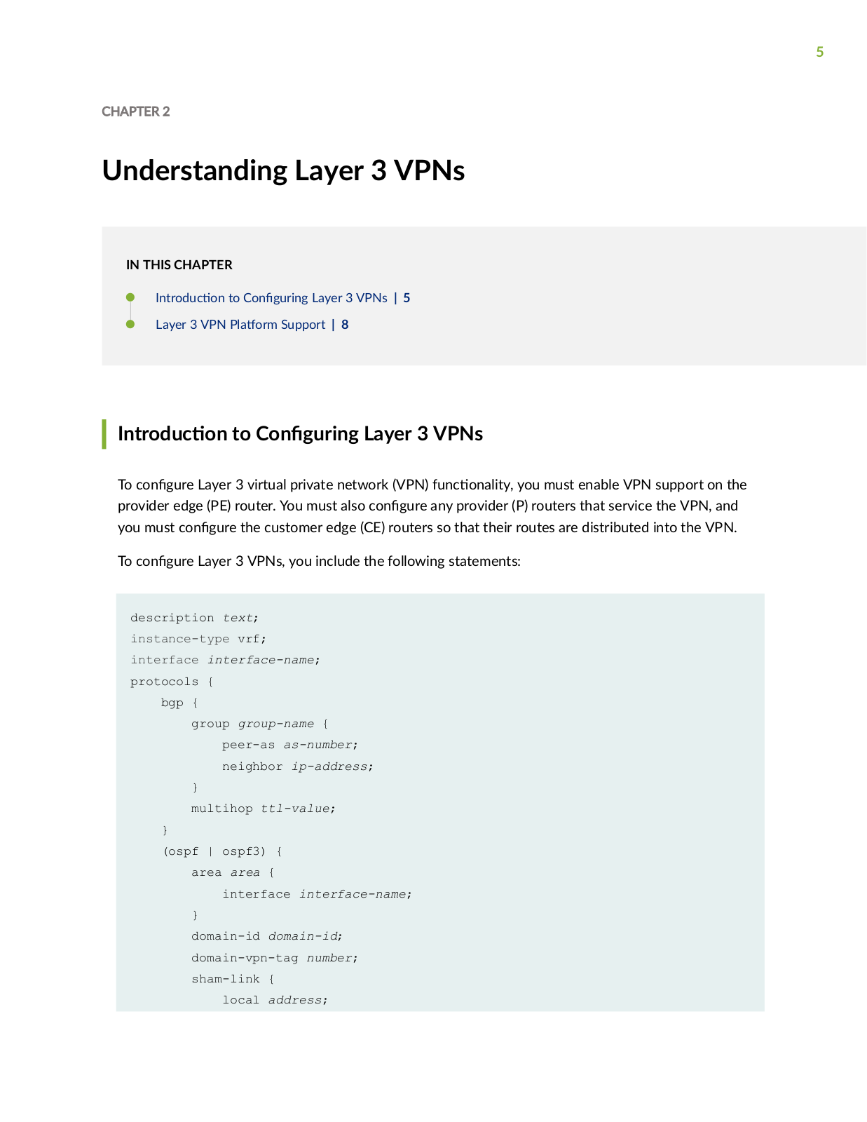
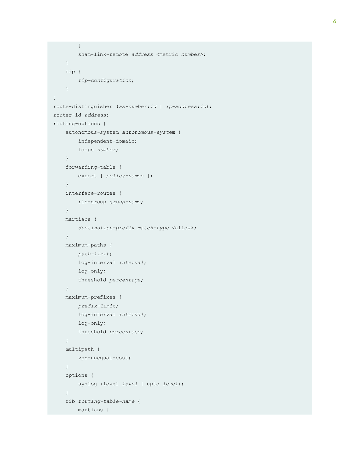
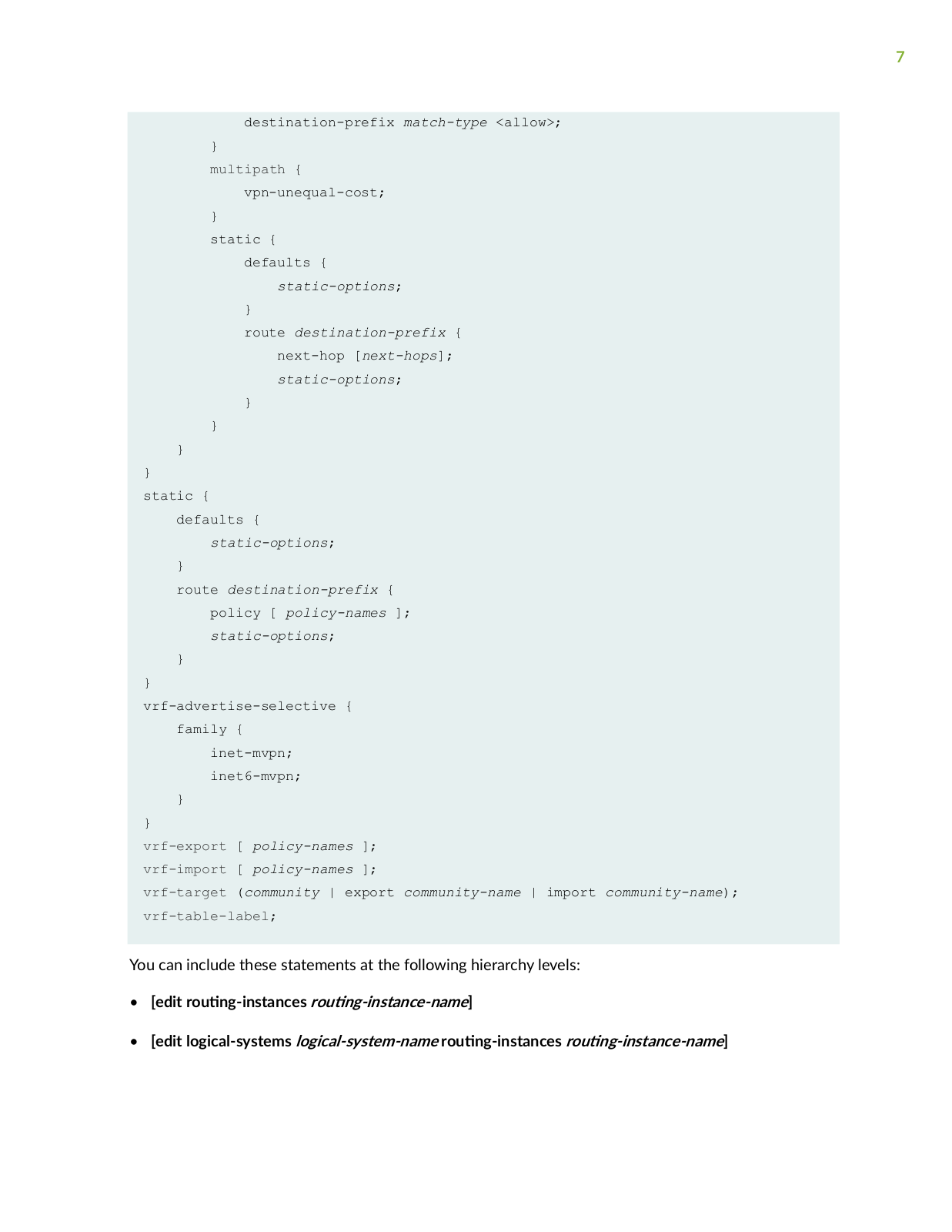
Layer 3 VPNs
Link and Multilink Services Interfaces
LN1000
2
LN1000 - RELEASE NOTES 8-27-2010
Logical Systems
2
M
M10
3
m10i
6
M120
2
M160
M20
4
M320
3
M40
3
M40E
3
M5
3
M7I
4
MAG2600
MEDIA FLOW CONTROLLER 2.0.4
2
MEDIA FLOW CONTROLLER 2.0.4 - ADMINISTRATOR S GUIDE AND CLI
MEDIA FLOW CONTROLLER 2.0.5
MEDIA FLOW CONTROLLER 2.0.5 - RELEASE NOTES REV 15-11-2010
MEDIA FLOW MANAGER 2.0.2 - ADMINISTRATOR S GUIDE AND CLI
MEDIA FLOW PUBLISHER
MESA
4
mesa 2
2
Mesa 3
Mesa Ethernet Dock
Mesa Rugged Notepad
Midsize Campus Design Using Mist Wired
Mist
MPLS
M Series
4
M-series M10i
M-series M7i
MULTICAST ROUTING - CONFIGURATION GUIDE V11.1.X
Multicast VPN
Multichassis Link Aggregation
Multiple VLAN Registration Protocol
MX10
3
MX10003
2
MX10008
3
MX10016
MX104
3
MX104 3D
MX150
4
MX2010
MX2020
3
MX204
2
MX240
8
MX240 3D
MX240 - UPGRADING
MX40
3
MX480
6
MX480 - UPGRADING
MX5
3
MX80
3
MX960
7
mx960 3D
MX960 - UPGRADING
MX Series
5
MX-series MX240
MX-series MX960
N
NETSCREEN-200 SERIES
NetScreen-204
NetScreen-208
NetScreen-25
NetScreen-50
NetScreen-5000 Series
2
Netscreen-5200
Netscreen-5400
NETSCREEN-5GT
2
NETSCREEN-ISG 2000
Network Address Translation
NETWORK AND SECURITY MANAGER
4
NETWORK AND SECURITY MANAGER 2010.2
NETWORK AND SECURITY MANAGER 2010.2 - ADMINISTRATION GUIDE REV1
NETWORK AND SECURITY MANAGER 2010.3
3
NETWORK AND SECURITY MANAGER 2010.3 - ADMINISTRATION GUIDE REV1
NETWORK AND SECURITY MANAGER 2010.3 - CONFIGURING INTRUSION DETECTION AND PREVENTION GUIDE REV1
NETWORK AND SECURITY MANAGER 2010.3 - M-SERIES AND MX-SERIES DEVICES GUIDE REV1
NETWORK AND SECURITY MANAGER 2010.4
4
NETWORK AND SECURITY MANAGER 2010.4 - ADMININISTRATION GUIDE REV1
NETWORK AND SECURITY MANAGER - NSM CONFIGURATION GUIDE FOR EX SERIES DEVICES REV 3
NETWORK AND SECURITY MANAGER - RELEASE NOTES REV 1
NETWORK AND SECURITY MANAGER - RELEASE NOTES REV 3
Loading...
Loading...
Nothing found
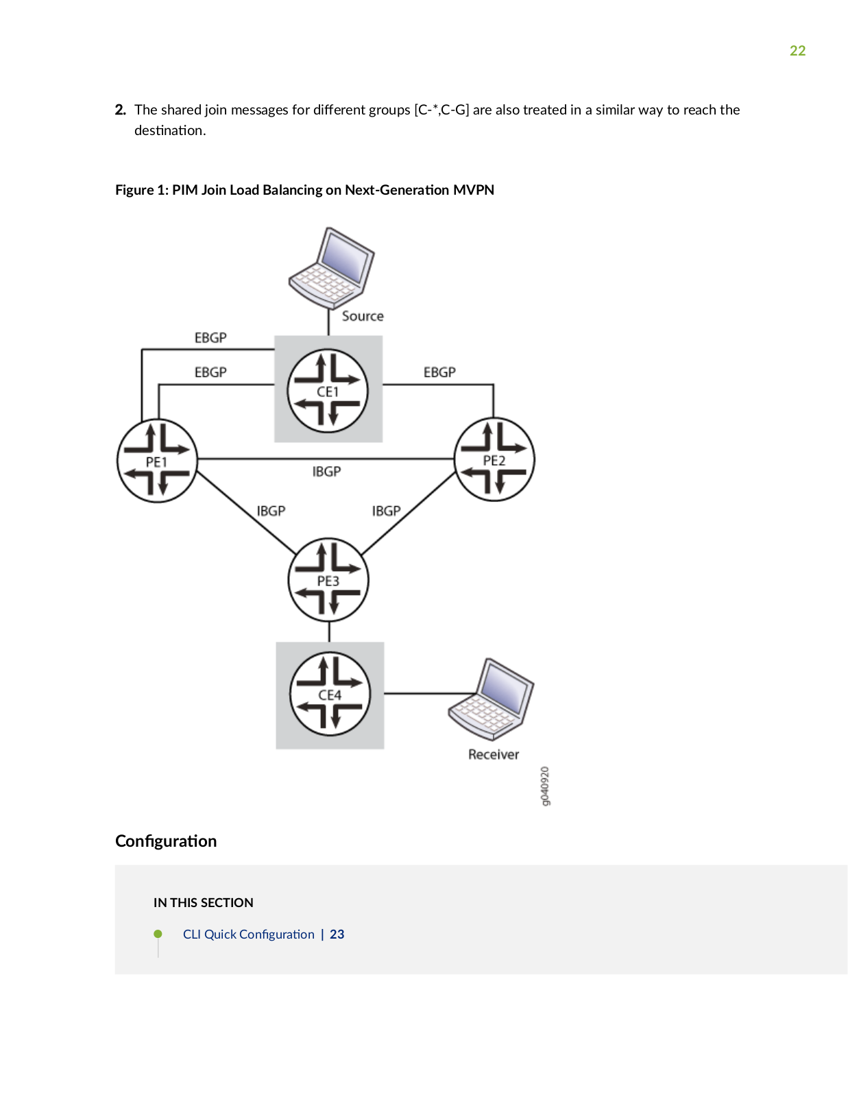
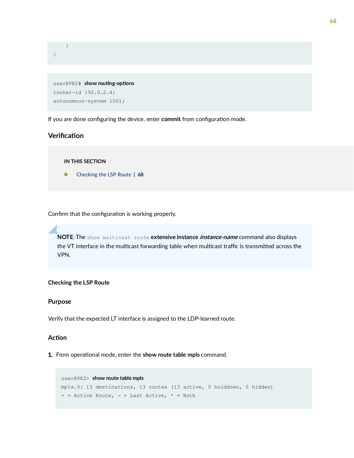
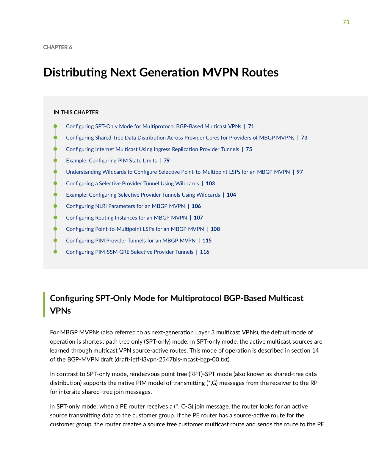
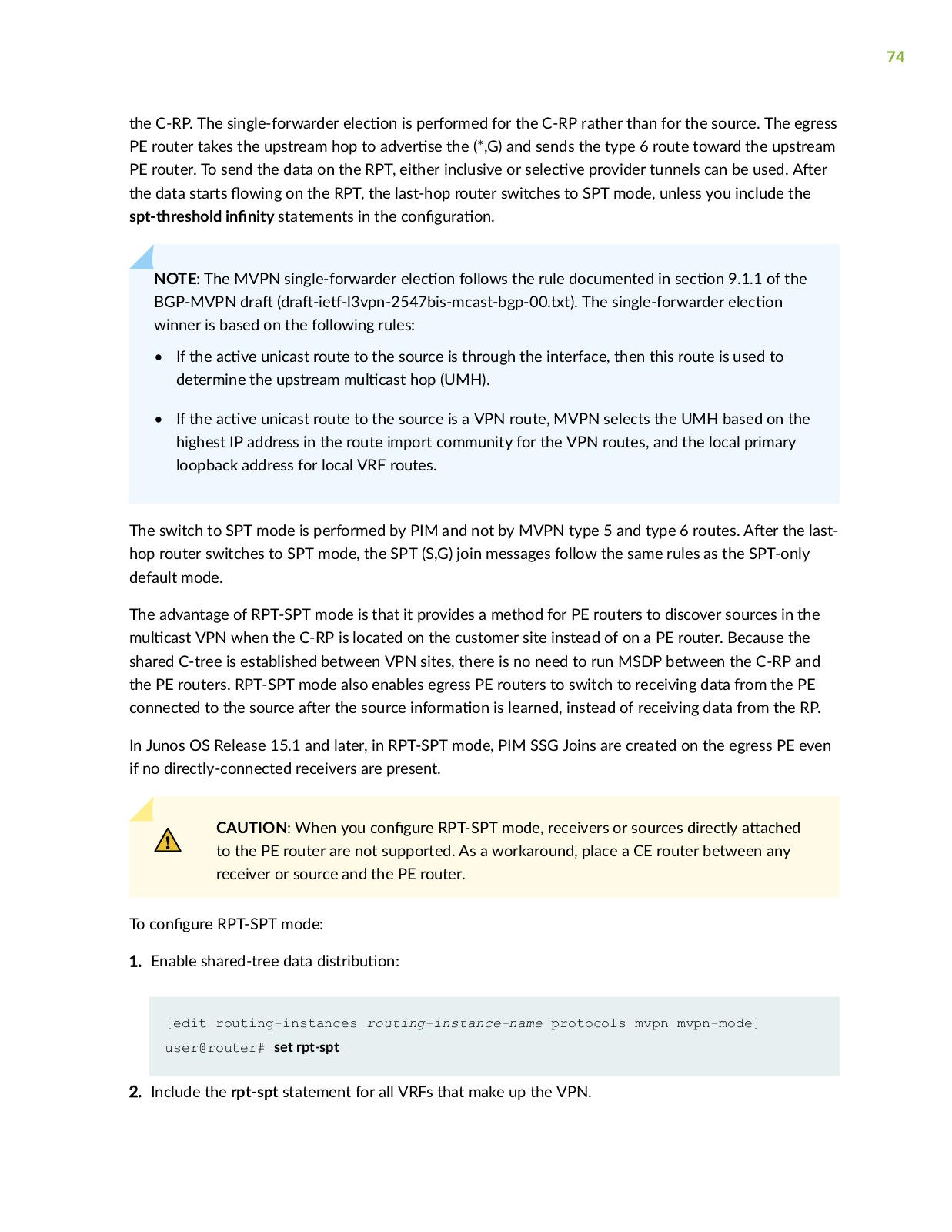
Multicast VPN
User Manual
230 pgs
886.02 Kb
0
Table of contents
Loading...
Juniper Multicast VPN User Manual
...
Juniper User Manual
Download
Specifications and Main Features
Frequently Asked Questions
User Manual
Download
Loading...
+
hidden pages
Unhide
You need points to download manuals.
1 point = 1 manual.
You can buy points or you can get point for every manual you upload.
Buy points
Upload your manuals
 Loading...