

Page 1

Reference Architecture
Published
2021-02-08
Midsize Campus Design Using Mist Wired
Assurance
Page 2

Juniper Networks, Inc.
1133 Innovation Way
Sunnyvale, California 94089
USA
408-745-2000
www.juniper.net
Juniper Networks, the Juniper Networks logo, Juniper, and Junos are registered trademarks of Juniper Networks, Inc. in
the United States and other countries. All other trademarks, service marks, registered marks, or registered service marks
are the property of their respective owners.
Juniper Networks assumes no responsibility for any inaccuracies in this document. Juniper Networks reserves the right
to change, modify, transfer, or otherwise revise this publication without notice.
Reference Architecture Midsize Campus Design Using Mist Wired Assurance
Copyright © 2021 Juniper Networks, Inc. All rights reserved.
The information in this document is current as of the date on the title page.
ii
YEAR 2000 NOTICE
Juniper Networks hardware and software products are Year 2000 compliant. Junos OS has no known time-related
limitations through the year 2038. However, the NTP application is known to have some difficulty in the year 2036.
END USER LICENSE AGREEMENT
The Juniper Networks product that is the subject of this technical documentation consists of (or is intended for use with)
Juniper Networks software. Use of such software is subject to the terms and conditions of the End User License Agreement
(“EULA”) posted at https://support.juniper.net/support/eula/. By downloading, installing or using such software, you
agree to the terms and conditions of that EULA.
Page 3

Table of Contents
1
Reference Architecture for a Midsize Campus Using Mist Wired Assurance
Overview: Midsize Campus Solution Using Mist Wired Assurance | 6
Introduction | 6
Framework | 6
Midsize Campus Solution Reference Architecture for Mist Wired Assurance | 8
Access Module | 8
Wired Access | 8
Wireless Access | 9
Aggregation Module | 10
iii
Edge Module | 11
Edge Firewall | 11
Edge Router | 12
Deploying Midsize Campus with Mist Wired Assurance | 13
Policy Orchestration | 13
Security | 15
Quality of Service | 15
High Availability | 16
High Availability at Layer 2 | 17
Spanning Tree Protocol (STP) | 17
Virtual Chassis | 18
High availability at Layer 3 | 19
Configure the SRX Series Device | 20
Connecting the SRX and Juniper EX Series Switch | 23
Configure the EX Series Switch in the Juniper Mist Cloud | 27
How to Activate a Brownfield Switch | 29
Troubleshooting | 31
Day 1: Use a Template-Based Configuration with Device and Port Profile | 32
Wireless Configuration on the Juniper Mist Cloud | 43
Additional SSID Configuration | 48
Page 4

Conclusion | 52
iv
Page 5

1
CHAPTER
Reference Architecture for a Midsize
Campus Using Mist Wired Assurance
Overview: Midsize Campus Solution Using Mist Wired Assurance | 6
Midsize Campus Solution Reference Architecture for Mist Wired Assurance | 8
Deploying Midsize Campus with Mist Wired Assurance | 13
Page 6
Overview: Midsize Campus Solution Using Mist Wired Assurance
IN THIS SECTION
Introduction | 6
Framework | 6
Introduction
6
Campus networks are constantly evolving and growing at a rapid rate. No longer merely comprised of
homogenous desktops and printers, a campus now includes an array of IP devices: phones, Juniper Access
Points, tablets, and more. Knowledge workers can work anywhere, as their access permits. Providing a
consistent experience, regardless of how or where the user connects, can increase the overall productivity.
Organizations must build a network that can provide flexibility while protecting critical data from
unauthorized access.
Framework
The Juniper Networks Midsize Campus solution is built upon a standard solution architectural approach.
The baseline architecture is based on a series of building blocks, built by Juniper Networks, that are meant
to address the entire network.
For the Midsize Campus Solution Reference Architecture using Mist Wired Assurance, the following
modules are detailed:
Access
•
Aggregation
•
Edge
•
Each of the modules take into consideration the following elements and design requirements:
Policy orchestration
•
Network management
•
Page 7
Security
g301232
Mist AP
EX4650
L3
L2
Collapsed Core
Access
EX2300/ EX3400/ EX4300
Employee
Guest
IoT
Employee
Guest
IoT
SRX Series Router
•
Quality of service (QoS)
•
High availability (HA) and resiliency
•
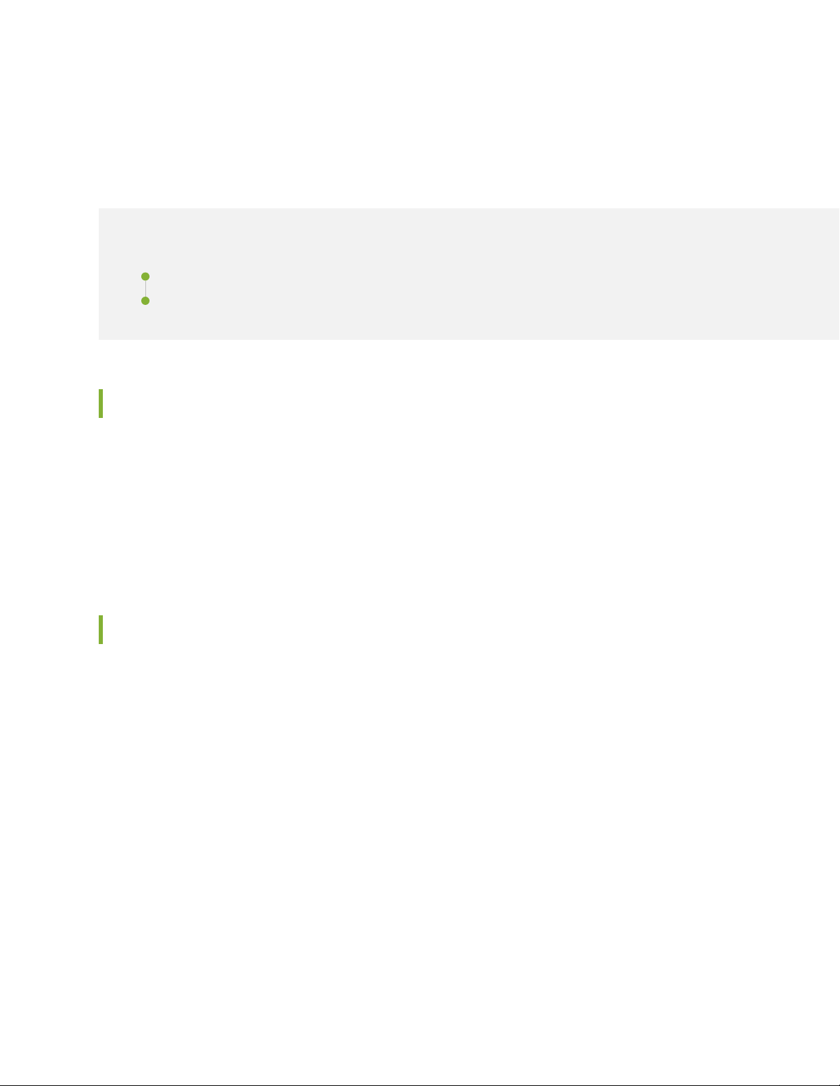
Figure 1 on page 7 illustrates the solution modules and the design considerations described in this
reference architecture.
Figure 1: Midsize Campus Solution Reference Architecture Framework
7
Page 8
Midsize Campus Solution Reference Architecture for Mist Wired Assurance
IN THIS SECTION
Access Module | 8
Aggregation Module | 10
Edge Module | 11
The solution reference architecture was designed using a modular approach. Each of the design modules
are described in detail in the following sections.
8
Access Module
The access module is comprised of:
Wired access
•
Wireless access
•
Wired Access
In a campus network, access switches provide network connectivity to end users by connecting IP-enabled
devices such as desktops, phones, and printers. Access layer switches typically reside in the wiring closets
of each floor in each physical campus facility.
Design recommendations for the access module are:
Port density—Needed for client connection, as well as an uplink to the aggregation/core layers to reduce
•
the client-to-uplink oversubscription ratio
Scalability—On a need-to-grow basis to help reduce capital and operating expenditures
•
Flexibility—Ability to enable port density and scalability regardless of where the physical infrastructure
•
is located
High availability (HA)—Redundant path, always-on power, and nonstop forwarding
•
Page 9

Power over Ethernet (PoE)—Ability to enable services to devices such as phones, video endpoints, and
•
Juniper Access Points without extra power cabling, reducing capital expenditures and simplifying cabling
infrastructure
Quality of service (QoS)—Classification, marking, and prioritization of traffic flows
•
Segmentation—Ability to maintain separation of traffic when needed
•
Security infrastructure integration—Access control to prevent unauthorized users and devices
•
The access layer serves as the pathway to all network services. This layer becomes a primary boundary of
access control for security requirements as well. Virtualization capabilities, such as virtual LANs (VLANs)
and virtual routers, are important for supporting required segmentation of the access layer network. Virtual
chassis provides the flexibility and scalability to support connectivity throughout the closet while simplifying
management. In addition, integrating network security with unified access control is another important
aspect. As a first line of defense, security controls such as broadcast storm control, Dynamic Host
Configuration Protocol (DHCP) snooping, and Address Resolution Protocol (ARP) spoofing protection
should be enabled to prevent service disruption to authorized clients. With increasing use of multicast
applications, it is also important to consider enabling multicast features such as Internet Group Management
Protocol (IGMP) snooping and Multicast Routing Protocol (MRP) support.
9
Wireless Access
In a campus environment, Juniper Access Points provide network access to end-user devices like access
switches. With increased wireless performance and proliferation of mobile devices, wireless connectivity
is becoming the primary mode of access on the campus network. Both real-time and bandwidth-demanding
applications are running over wireless networks. However, the user expects the same level of network
services (security, QoS, accessibility, and HA) as with a wired connection. Wireless access must be robust
and reliable to deliver these demands.
In a Mist enabled wireless LAN (WLAN) design, only the Juniper Access Point is required for access. The
Juniper Access Point transmits a radio frequency (RF) signal on a configured set of channels. Wireless
clients then associate with the AP to establish a wireless connection. An 802.1Q trunk for the AP to the
access switch is configured so that wireless traffic enters the wired network directly on access switches.
This WLAN approach can provide comparable performance to a wired connection; however, it is not
scalable because each individual Juniper Access Point must be configured manually.
Without a centralized component that can control and store critical information, several challenges can
arise. For instance, as users roam from Juniper Access Point to Juniper Access Point, they might experience
service disruptions. As a wireless client associates with a Juniper Access Point, the nearest Juniper Access
Point recognizes the client information and establishes a network connection. If the client roams outside
the RF coverage of the associated Juniper Access Point, the client will experience a dropped connection
and then attempt to re-associate with the next nearest Juniper Access Point. Managing RF spectrum on
a per Juniper Access Point basis becomes cumbersome, where one Juniper Access Point might impede
upon another Juniper Access Point’s signal, or in other cases not carry enough signal at all. Rogue wireless
Page 10

devices can also become an issue, since it becomes burdensome to locate when unauthorized wireless
clients enter the network without a centralized authentication point.
Aggregation Module
The aggregation layer aggregates connections and traffic flows from multiple access layer switches and
wireless networks to provide high-density connectivity to the campus core.
Design recommendations for the aggregation module are:
Scalability
•
High-performance and throughput
•
HA
•
Network services integration
•
10
QoS support
•
Full N + 1 or N + N hardware redundancy
•
Control plane redundancy
•
Ability to upgrade the software while in-service
•
Ability to combine physical chassis into a single, logical control plane
•
Aggregation layer switches must offer high-density ports to provide maximum scalability, along with
wire-rate forwarding for maximum throughput. Also, a non-blocking architecture at the aggregation layer
is important to minimize the oversubscription ratio, because a large number of client connections are
supported through these devices. Therefore, it is critical to have HA hardware and software features that
deliver reliability and robustness. For device-level redundancy, the aggregation hardware should be deployed
in pairs. The primary function of the aggregation layer infrastructure is to provide high throughput and
non-blocking switching/routing fabric. The dynamic routing protocol support, high-performance control
plane, and high-capacity data plane are important features of aggregation layer devices.
In a midsize enterprise campus, the aggregation layer is not as distributed as the access layer, which makes
it easier to place your security defenses and introduce segmentation using virtual routers or VLANs to
contain threats. Traffic control with QoS capabilities, such as multiple queues, queue capacity, and integration
help run real-time applications and prioritize critical applications appropriately. For multicast applications
support, Multicast Routing Protocol (MRP) and efficient multicast replication techniques are important in
aggregation layer devices.
The aggregation switch has the primary responsibility of multiplexing a large set of access ports into a
smaller set of ports that can be consumed by the core switch. Because the aggregation switch multiplexes
a high number of access ports, the scale requirements increase linearly for every access port it aggregates.
For example, if an access switch supports 10,000 MAC addresses and the aggregation switch consolidated
Page 11

100 access switches, the total MAC scale required at the aggregation switch is 10,000 x 100 = 1,000,000
MAC addresses.
Edge Module
The edge module is the gateway for remote access to the campus network. Also, the edge module
aggregates, inspects, and encapsulates all traffic coming in and out of campus core to the Internet. The
edge is viewed as the primary path for all campus network egress and ingress.
The edge module is comprised of:
Edge firewall
•
Edge router
•
Edge Firewall
11
An edge firewall provides perimeter security services such as traffic inspection, access policies, network
address translation (NAT), and IPSec. All traffic leaving out of and arriving into the campus must pass
through the edge firewall. This is enforced through physically cabling the edge firewall between the edge
routers and core switch as well as the capability to permit and deny certain types of traffic.
The edge firewall must address the following security and tunneling considerations:
Ability to create granular firewall filters that can inspect Layer 2 through Layer 4 traffic
•
Support unicast reverse path forwarding modes: loose, strict, and VRF
•
Support SSH
•
IPSec
•
GRE
•
To resolve IP address conflicts and bridge IPv6 islands, the edge firewall must support a wide variety of
Network Address Translation (NAT) protocols:
Basic NAT44
•
NAPT44
•
NAPT66
•
Twice NAT44
•
NAPT-PT
•
To provide HA and reliable services, edge firewalls support clustering with active/passive failover. In
active/passive failover one firewall node remains active and handles all control plane processing and data
Page 12

plane forwarding. In the event of a failure, the secondary node takes over and then becomes the primary
node.
Edge Router
An edge router connects the campus network to the service provider for Internet access. HA must be a
priority at the edge router, because the router serves as the primary connection between the campus
network and the Internet. It is also considered the first line of defense for attacks coming from the Internet.
Ability to limit what type of traffic can access the control plane
•
Ability to determine specific types of ingress control plane traffic and enforce packets per second (PPS)
•
limitations
Ability to police traffic to a certain bandwidth and penalizing excess traffic by changing the forwarding
•
class or simply discarding the traffic
Ability to create granular firewall filters that can inspect Layer 2 through Layer 4 traffic
•
Support unicast reverse path forwarding (URPF) modes: loose, strict, and VRF
•
12
Full N + 1 or N + N hardware redundancy
•
Control plane redundancy
•
Ability to upgrade the software while still remaining in-service
•
Link aggregation
•
Loop-free alternates
•
Default gateway redundancy
•
There are various network protocols coming from the Internet to the edge router. The following protocol
families must be supported on the edge router:
IPv4
•
IPv6
•
ISO
•
MPLS
•
The edge router must also support widely deployed routing protocols. The following routing protocols
must be supported on the edge router:
Static routes
•
RIP
•
OSPF
•
OSPF-TE
•
Page 13
OSPFv3
•
IS-IS
•
BGP
•
Deploying Midsize Campus with Mist Wired Assurance
IN THIS SECTION
Policy Orchestration | 13
Security | 15
Quality of Service | 15
High Availability | 16
13
High Availability at Layer 2 | 17
Spanning Tree Protocol (STP) | 17
Virtual Chassis | 18
High availability at Layer 3 | 19
Configure the SRX Series Device | 20
Connecting the SRX and Juniper EX Series Switch | 23
Configure the EX Series Switch in the Juniper Mist Cloud | 27
How to Activate a Brownfield Switch | 29
Troubleshooting | 31
Day 1: Use a Template-Based Configuration with Device and Port Profile | 32
Wireless Configuration on the Juniper Mist Cloud | 43
Additional SSID Configuration | 48
Conclusion | 52
Policy Orchestration
With the proliferation of mobiles devices and ubiquitous Internet availability, employees and guest users
need to connect to the campus network, regardless if whether they are on the premises or working remotely.
Users likewise need connect using corporate devices as well as their own (BYOD), all with the same level
Page 14

of security and access experience. These requirements demand role-based policy orchestration. Indeed,
policy orchestration and access control are two of the more critical elements in delivering a secure
infrastructure for the midsize enterprise campus solution because they provide a comprehensive suite of
features for device connectivity and security. When users connect to the network, the policy orchestration
engine must:
Identify the user and the role of the user.
•
Authenticate and authorize the user.
•
Identify whether or not the client device of the user is company-owned or BYOD.
•
Identify the type of OS running on the client devices (MAC OSX, PC Windows, or other).
•
Quarantine the device if necessary.
•
Detect the location of the entry point.
•
Detect traffic encryption requirements.
•
Provide accountability of user access (for example, report the number of attempts and success rate).
•
14
Likewise, the access control must provide:
Guest access control.
•
Layer 2 access control (802.1X, MAC authentication).
•
MAC authorization and device profiling.
•
Protection against MAC spoofing.
•
Monitoring and containment of unauthorized connections.
•
Role-based access control.
•
Identity-aware networking (Network Access Control (NAC) and Identity and Access Management (IAM)).
•
This Midsize Campus solution uses Mist Wired Assurance and supports both user parameters and device
MACs for access control. Using a mix of user-based and MAC-based authentication methods provides
scale, as does the use of a dedicated LDAP back-end server.
Creating a WLAN (SSID) specific for guest users (such as vendors or contractors) allows them to be separated
from corporate users, so, for example, they can enter the network without a corporate device or supplicant.
DUA (Device/User/Application) Profiles determine the number of devices (with MAC association) and
number of users including guests. In this example, we assumed guest access users will make up about 10
percent of total users.
Use Interface for Metadata Access Point (IF-MAP) protocol for session information transfers to the secure
access server in real time. (IF-MAP is an open standard protocol that communicates information about
sessions, roles, access zones, and other elements between clients to the server as a federation.)
Page 15

When setting up your own network to implement this example, you include support for active/passive or
active/active high availability (note that active/passive set up can limit performance, but you can use load
balancing to help scale nonclustered nodes and increase performance.)
You can also use additional services or service modules in the same chassis to support remote access
services and network access control (NAC) policy services as part of an overall security strategy managed
by a security management server.
Security
Robust security is important to the campus environment. This includes perimeter security, which must
provide stateful firewall protection ingress and egress to the campus network as well as protect all traffic
within the various silos of the campus network. Part of the security posture for the solution is also to
provide role-based access control (RBAC) to the network, including AAA in conjunction with 802.1x, which
provides an endpoint access authentication model.
15
Additional device security should be associated to headless network devices, such as printers and video
surveillance cameras, to provide the ability to prevent MAC spoofing attempts with these types of devices
which have the inability to provide traditional AAA credentials.
Access security posture for the Campus solution should allow authenticated endpoints to be dynamically
allocated to different VLANs automatically. Activation and transmission of firewall filters and VLAN
assignments should be supported on access switches with a policy provided by an authentication server.
If the authentication server cannot be reached, switches will support an authorization failed policy, in
which devices are set to a non-authenticated state. Authenticated ports will remain authenticated for the
duration of the connected session until the device is disconnected (either physically or logically) or the
policy has timed out. The switch ports will also provide a method to grant trusted access to resources,
while denying non-authenticated devices or providing only limited access to a remediation service.
Quality of Service
Quality of service (QoS) is an essential design category for maintaining application and user real-time
performance monitoring (RPM) and ensuring consistent performance of the network. Although the Midsize
Enterprise Campus solution reference architecture is designed for high bandwidth services with gigabit
Ethernet or 10GE links, QoS should be considered mandatory for any campus deployment, regardless of
bandwidth, for any interface or access point with the potential for congestion or contention for resources.
QoS policies are implemented for per-hop-behavior (PHB), meaning that each device should be configured
to ensure consistent end-to-end policy enforcement. Although QoS policies are implemented as PHB, QoS
Page 16
should be considered end-to-end and flow through the entire campus in order to correctly adhere to the
g301423
Mist AP
EX4650
L3
L2
Collapsed Core
Access
Employee
Guest
IoT
Employee
Guest
IoT
SRX Series Router
EX2300
EX3400
EX4300
Multifield classifiers
Rewrite Rules
BA Classifiers
Rate Limiting
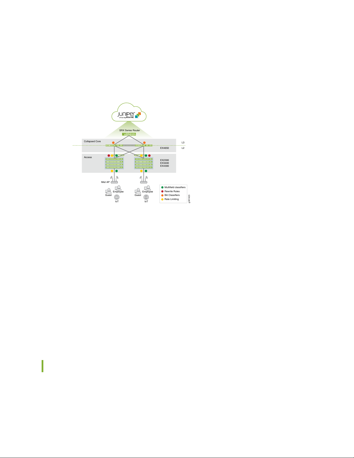
RPMs of the specific applications and campus policies.
Figure 2 on page 16 illustrates the QoS classification used in the validated reference architecture.
Figure 2: QoS Classification of Traffic
16
QoS policies are first established by setting the trust boundaries and the relationships of marking the traffic
in the campus network. For this reference architecture, trusted relationships (trusted inter-switch policies)
are established at the aggregation and core layers of the network. In a trusted relationship, the classifications
and markings of the traffic do not require a rewrite or an inspection. However, queuing and policing policies
should be considered at the ingress and egress of all inter-switch links. WAN policies (both to the corporate
WAN and to the Internet) can be constrained by lower bandwidth access links (less than 100 MB) and thus
require a QoS policy with queuing and policing applied to maintain RPMs . Depending on the inbound and
outbound QoS policy for the campus, WAN links can have different levels of trust associated with the
interface. The access layer should be considered untrusted. At the access layer, QoS access policies include
queuing, policing, classification, marking, and rewriting for ingress traffic. Based on the campus QoS policy,
some devices may be considered trusted, such as an IP phone, which would receive its marking policy from
the corporate IP PBX. WLAN QoS policies are configured at the WLAN controller, which provides the
campus administrator the ability to trust the client DSCP through the wireless connection.
For more information on setting up QoS from the Juniper Mist portal, see: QoS for Switches
High Availability
High availability (HA) and resiliency is essential for maintaining connectivity and avoiding service disruption.
The expectation in this Midsize Enterprise Campus Solution Reference Architecture is to ensure
uninterrupted (sub-second recovery) access, including during voice and video sessions, in the event of
Page 17
hardware or software failure in the network. Additionally it assumed, there is the ability to minimize
g301379
Switch 2
Switch 3
Switch 1
Layer-2
Loop
downtime during planned outages through the use of features such as nonstop routing (NSR), nonstop
bridging (NSB), and nonstop software upgrades (NSSU).
High Availability at Layer 2
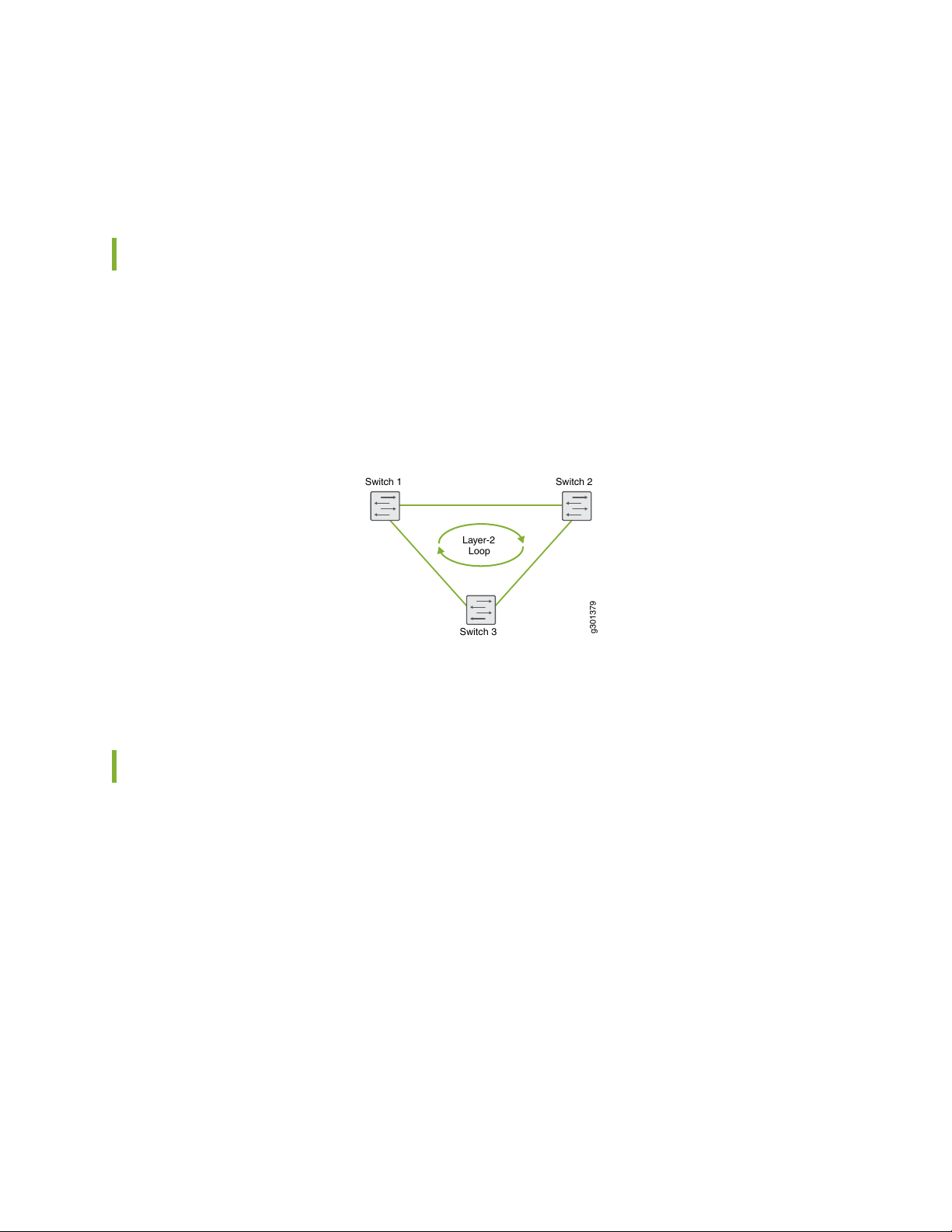
In campus architecture, each access switch is connected to two aggregation switches for redundancy to
provide reliability and HA. Aggregation switches are interconnected at Layer 2. As shown in
Figure 3 on page 17, this can create a Layer 2 loop. Ethernet does not have any inherent way to track
frames that are looping.
Figure 3: Layer 2 Loop
17
The following techniques are detailed to address Layer 2 looping.
Spanning Tree Protocol (STP)
Spanning Tree Protocol (STP) is the industry standard for preventing Layer 2 loops. STP calculates the best
path through a switched network that contains redundant paths. STP uses bridge protocol data unit (BPDU)
data frames to exchange information with other switches. STP uses the information provided by the BPDUs
to elect a root bridge, identify root ports for each switch, identify designated ports for each physical LAN
segment, and prune specific redundant links to create a loop-free tree topology. The resulting tree topology
provides a single active Layer 2 data path between any two endpoints, as shown in Figure 4 on page 18.
Page 18

Figure 4: Spanning Tree Protocol
g301380
Switch 2
Switch 3
Switch 1
Although STP can prevent Layer 2 loops, it is not an efficient protocol. At any given time, a Layer 2 switch
port can be listening, learning, forwarding, or blocking in order to determine the loop-free data path. Many
improvements have been made to STP to improve its convergence time from 50 seconds to much less.
However, STP does not perform sub-second convergence like most Layer 3 protocols can. Another
disadvantage of STP is that it blocks all but one of the redundant paths that are connected. As a result,
network resources can be under-utilized as there are occupied switch ports not actively in use (because
they are in a blocking state). Real-time applications suffer most when STP is used alone in a campus
environment. To avoid the performance limitations of STP, this reference architecture used virtual chassis.
18
Virtual Chassis
Virtual chassis is an intelligent technique for avoiding Layer 2 looping altogether. As shown in
Figure 5 on page 18, multiple switches are brought under a single management and control plane, creating
a virtual device that consists of two or more physical devices.
Figure 5: Virtual Chassis
In a virtual chassis, each of the member devices are stacked together to act as single logical device. In a
virtual chassis connection, there is a client device, such as a server or switch that has more than one physical
link into the virtual chassis. This client device does not need to have any virtualization configured. On the
other side of the connection is the virtual chassis. Each of the virtual chassis stack members has one or
more physical links connected to the client device.
Page 19

High availability at Layer 3
Every network element in the Campus solution ultimately converges into the core switch, which functions
as the core of Layer 3 for the campus network. As such, the core switches of the campus must support
high port speed and density, high availability and resiliency, a robust feature set, and scalability.
OSPF is used on the core switch, as the interior gateway protocol in this reference architecture (some
campus networks might elect to use IS-IS). In addition, the core switch enables the loop-free alternate
(LFA) feature in OSPF to converge faster during link and node failures. To detect forwarding errors and
help enable faster end-to-end convergence, the Bidirectional Forwarding Detection (BFD) protocol should
be enabled on all point-to-point and broadcast interfaces.
The recommended values for routing convergence for this reference architecture are:
Minimum interval of 50ms
•
Multiplier of 3
•
Neighbor authentication should be enabled between each node in the topology using either MD5 or SHA-1
encryption; the intent is to prevent accidental OSPF adjacencies in the future if new equipment is installed.
There are various physical, logical, and software components that need to be configured to support
redundancy between the core switches.
19
Physical redundancy:
Redundant power supplies
•
Redundant routing engines
•
Redundant switching fabric
•
Redundant line cards
•
Routing engine redundancy:
Graceful Routing Engine switchover (GRES)
•
Nonstop routing (NSR)
•
Nonstop bridging (NSB)
•
Non-Stop Service Software Upgrade (NSSU)
•
Protocol availability:
BFD enabled on all links
•
LFA enabled on all links
•
QoS properly configured to give network control adequate bandwidth during times of congestion
•
Page 20

Configure the SRX Series Device
This example shows how to configure the SRX Series device starting logically from the lower layers to the
upper layers of the network. In it, we set up four branch offices, each with a different VLAN, and all of
which connect to the corporate intranet. Wi-Fi users at the branches connect to the network via access
points that are connected to one of the respective VLANs configured on the SRX.
1. Set the hostname and password. For this example, use Mist-SRX-GW as the hostname and for the sake
of simplicity, configure the root password using plain text rather than encrypted:
set system host-name Mist-SRX-GW
set system root-authentication plain
2. Configure the time zone and add both a DNS server and an NTP server. For this example, set the time
zone to America/Los_Angeles and use an IP address of 8.8.8.8 for the DNS server and an IP address
of 216.239.35.12 for the NTP server.
20
set system time-zone America/Los_Angeles
set system name-server 8.8.8.8
set system ntp server 216.239.35.12
3. Next, create the four VLANs. Use Table 1 on page 20 to see the VLANs, usage, and port types used in
this example.
set vlans vlan10 vlan-id 10
set vlans vlan20 vlan-id 20
set vlans vlan30 vlan-id 30
set vlans vlan40 vlan-id 40
Table 1 on page 20 lists the VLANs, usage, and port type used in this example. All other ports on the
SRX Series device and EX switch are untagged VLAN ports.
Table 1: VLAN Usage
SRX to EX Port
TypeNameVLAN IDVLAN
Usage
untaggedDefault1vlan1
Default VLAN and provides in band
management for all devices.
Used by corporate wired and wireless traffic.taggedCorp10vlan10
Page 21

Table 1: VLAN Usage (continued)
SRX to EX Port
TypeNameVLAN IDVLAN
21
Usage
Used by guest wireless devices.taggedGuest20vlan20
Used by all IoT devices.taggedIoT30vlan30
Used by the surveillance cameras.taggedCameras40vlan40
—Restricted99vlan99
Used in switch ports where a dynamic profile
is assigned a default restricted VLAN.
4. For the primary link to the Internet, we’ll use interface ge-0/0/6, and also configure it as a DHCP client.
set interfaces ge-0/0/6 unit 0 description "WAN Interface 1 - Primary"
set interfaces ge-0/0/6 unit 0 family inet dhcp vendor-id Juniper-srx320
5. In this step, we create a security policy to allow traffic between the trusted and untrusted zones.
set security policies from-zone trust to-zone untrust policy allow-in-zone match
source-address 192.168.1.0/24
set security policies from-zone trust to-zone untrust policy allow-in-zone match
source-address 10.1.10.0/24
set security policies from-zone trust to-zone untrust policy allow-in-zone match
source-address 10.1.20.0/24
set security policies from-zone trust to-zone untrust policy allow-in-zone match
source-address 10.1.30.0/24
set security policies from-zone trust to-zone untrust policy allow-in-zone match
source-address 10.1.40.0/24
set security policies from-zone trust to-zone untrust policy allow-in-zone match
destination-address any
set security policies from-zone trust to-zone untrust policy allow-in-zone match
application any
6. The EX switch needs to be able to access the Juniper Mist cloud. For this, we need to configure the
security zones and the SRX so the connected EX switch can obtain an IP address from the DHCP pool,
and so it can connect to the Internet.
Modify the security policy to allow ICMP ECHO (ping) and DHCP service messages in the trusted
security zone and add the irb.0 interface to the security zone.
Page 22

set security zones security-zone LAN-NETs host-inbound-traffic system-services
ping
set security zones security-zone trust host-inbound-traffic system-services dhcp
set security zones security-zone LAN-NETs interfaces irb.0
7. Create source network address translations (NATs) for the VLANs used in this example.
set security nat source rule-set trust-to-untrust from zone LAN-NETs
set security nat source rule-set trust-to-untrust to zone inet
set security nat source rule-set trust-to-untrust rule source-nat-rule match
source-address [ 192.168.1.0/24 10.1.10.0/24 10.1.20.0/24 10.1.30.0/24
10.1.40.0/24 ]
set security nat source rule-set trust-to-untrust rule source-nat-rule match
destination-address 0.0.0.0/0
set security nat source rule-set trust-to-untrust rule source-nat-rule match
application any
set security nat source rule-set trust-to-untrust rule source-nat-rule then
source-nat interface
22
8. Configure the system logs that we will need to collect from the SRX device. In this example, we set the
maximum size of the Syslog to 100KB, keep the 3 most recent files only, set the files readable by all
users, and add all emergency log messages related to users to the syslog.
In addition, we configured our system logs to capture the following syslog messages:
File SizeSyslog file NameMessages
100 KBLOG-MessagesSeverity level messages from all facilities
Severity level messages from the authorization facility
LOG-Interactive-CommandsAny severity level message from the interactive
commands facility
1 MBLOG-Accepted-TrafficRT_FLOW_SESSION_CREATE events
1 MBLOG-Blocked-TrafficRT_FLOW_SESSION_DENY
1 MBLOG-SessionsRT_FLOW
Page 23

set system syslog archive size 100k
set system syslog archive files 3
set system syslog archive world-readable
set system syslog user * any emergency
set system syslog file LOG-Messages any notice
set system syslog file LOG-Messages authorization info
set system syslog file LOG-Interactive-Commands interactive-commands any
set system syslog file LOG-Accepted-Traffic any any
set system syslog file LOG-Accepted-Traffic match RT_FLOW_SESSION_CREATE
set system syslog file LOG-Accepted-Traffic archive size 1m
set system syslog file LOG-Accepted-Traffic archive files 3
set system syslog file LOG-Blocked-Traffic any any
set system syslog file LOG-Blocked-Traffic match RT_FLOW_SESSION_DENY
set system syslog file LOG-Blocked-Traffic archive size 1m
set system syslog file LOG-Blocked-Traffic archive files 3
set system syslog file LOG-Sessions any any
set system syslog file LOG-Sessions match RT_FLOW
set system syslog file LOG-Sessions archive size 1m
set system syslog file LOG-Sessions archive files 3
23
9. Commit the configuration
commit and-quit
Now that the SRX is configured for the EX switch to access the Internet, the next thing to do is to set up
the EX switch so it can be managed from the Juniper Mist portal
Connecting the SRX and Juniper EX Series Switch
In this part of the example, we configure an SRX to provide the wired and wireless network connections
for on-site employees, and wireless access to guest devices. The EX switch connects to the SRX device
and provides the Layer 2 functionality and ports for the branch.
To follow the steps in this example, you need to log on to your SRX and be able to edit the Junos
configuration.
Table 2 on page 24 contains the list of the interfaces, VLAN IDs, and IP address used in this example. You
can print out the table and modify the information to fit the variables of your own network, or swap in
those values when you copy/paste commands shown in steps 1 through 6.
Page 24

Table 2: VLAN and IP Address on the Interfaces
24
Network MaskIP AddressVLAN IDInterface
—DHCP—dl.0
255.255.255.0DHCP—ge-0/0/6
—DHCP—ge-0/0/7
255.255.255.0192.168.1.11Irb.0
255.255.255.010.1.10.110ge-0/0/0.10
255.255.255.010.1.20.120ge-0/0/0.20
255.255.255.010.1.30.130ge-0/0/0.30
255.255.255.010.1.40.140ge-0/0/0.40
1. We’ll start by configuring the interface that connects the SRX and the EX. The Junos CLI commands
below create VLANs (as defined in Table 1 on page 20), set VLAN 1 as the native VLAN, attach VLANs
to a physical interface on the device, and assign IPv4 addresses to different units on that interface.
set interfaces ge-0/0/0 flexible-vlan-tagging
set interfaces ge-0/0/0 native-vlan-id 1
set interfaces ge-0/0/0 unit 1 vlan-id 1
set interfaces ge-0/0/0 unit 1 family inet address 10.1.10.1/24
set interfaces ge-0/0/0 unit 20 vlan-id 20
set interfaces ge-0/0/0 unit 20 family inet address 10.1.20.1/24
set interfaces ge-0/0/0 unit 30 vlan-id 30
set interfaces ge-0/0/0 unit 30 family inet address 10.1.30.1/24
set interfaces ge-0/0/0 unit 40 vlan-id 40
set interfaces ge-0/0/0 unit 40 family inet address 10.1.40.1/24
2. Now we’ll create a security zone named trust on the interface, and include in it the VLANs (by way of
their respective interface unit IDs).
set security zones security-zone trust interfaces ge-0/0/0.10
set security zones security-zone trust interfaces ge-0/0/0.20
set security zones security-zone trust interfaces ge-0/0/0.30
set security zones security-zone trust interfaces ge-0/0/0.40
Page 25

3. Corporate devices connecting on VLAN10 will need an IP address, so here we configure interface
ge-0/0/0.10 to be the DHCP server address, create a DHCP server, and define an IP address pool for
the connecting devices.
set system services dhcp-local-server group CORP-NET interface ge-0/0/0.10
set access address-assignment pool CORP-NET_DHCP-POOL family inet network
10.1.10.0/24
set access address-assignment pool CORP-NET_DHCP-POOL family inet range
CORP-NET_DHCP-POOL---IP-RANGE low 10.1.10.10
set access address-assignment pool CORP-NET_DHCP-POOL family inet range
CORP-NET_DHCP-POOL---IP-RANGE high 10.1.10.100
set access address-assignment pool CORP-NET_DHCP-POOL family inet dhcp-attributes
domain-name MyMistLAB.com
set access address-assignment pool CORP-NET_DHCP-POOL family inet dhcp-attributes
name-server 8.8.8.8
set access address-assignment pool CORP-NET_DHCP-POOL family inet dhcp-attributes
router 10.1.10.1
25
4. As with the previous step, we’ll create a DHCP server and an IP address pool for guest users to connect
on VLAN20. Interface ge-0/0/0.20 will be the DHCP Server address.
set system services dhcp-local-server group GUEST-NET_DHCP-POOL interface
ge-0/0/0.20
set access address-assignment pool GUEST-NET_DHCP-POOL family inet network
10.1.20.0/24
set access address-assignment pool GUEST-NET_DHCP-POOL family inet range
GUEST-NET_DHCP-POOL---IP-RANGE low 10.1.20.10
set access address-assignment pool GUEST-NET_DHCP-POOL family inet range
GUEST-NET_DHCP-POOL---IP-RANGE high 10.1.20.100
set access address-assignment pool GUEST-NET_DHCP-POOL family inet dhcp-attributes
domain-name MyMistLAB.com
set access address-assignment pool GUEST-NET_DHCP-POOL family inet dhcp-attributes
name-server 8.8.8.8
set access address-assignment pool GUEST-NET_DHCP-POOL family inet dhcp-attributes
router 10.1.20.1
5. Next, we’ll create a DHCP server and an IP address pool for IoT devices connecting on VLAN30.
Interface ge-0/0/0.30 will be the DHCP server address.
set system services dhcp-local-server group IOT-NET_DHCP-POOL interface
ge-0/0/0.30
set access address-assignment pool IOT-NET_DHCP-POOL family inet network
Page 26

10.1.30.0/24
set access address-assignment pool IOT-NET_DHCP-POOL family inet range
IOT-NET_DHCP-POOL---IP-RANGE low 10.1.30.10
set access address-assignment pool IOT-NET_DHCP-POOL family inet range
IOT-NET_DHCP-POOL---IP-RANGE high 10.1.30.100
set access address-assignment pool IOT-NET_DHCP-POOL family inet dhcp-attributes
domain-name MyMistLAB.com
set access address-assignment pool IOT-NET_DHCP-POOL family inet dhcp-attributes
name-server 8.8.8.8
set access address-assignment pool IOT-NET_DHCP-POOL family inet dhcp-attributes
router 10.1.30.1
6. Finally, we’ll create a DHCP server and an IP address pool for camera devices connecting on VLAN40.
Interface ge-0/0/0.40 will be the DHCP Server address.
set system services dhcp-local-server group CAMERA-NET_DHCP-POOL interface
ge-0/0/0.40
set access address-assignment pool CAMERA-NET_DHCP-POOL family inet network
10.1.40.0/24
set access address-assignment pool CAMERA-NET_DHCP-POOL family inet range
CAMERA-NET_DHCP-POOL---IP-RANGE low 10.1.40.10
set access address-assignment pool CAMERA-NET_DHCP-POOL family inet range
CAMERA-NET_DHCP-POOL---IP-RANGE high 10.1.40.100
set access address-assignment pool CAMERA-NET_DHCP-POOL family inet
dhcp-attributes domain-name MyMistLAB.com
set access address-assignment pool CAMERA-NET_DHCP-POOL family inet
dhcp-attributes name-server 8.8.8.8
set access address-assignment pool CAMERA-NET_DHCP-POOL family inet
dhcp-attributes router 10.1.40.1
26
7. Commit the configuration.
commit and quit
The EX switch and Juniper Access Points are now connected on the trunk port and the EX switch can
connect to the Internet, and thus the Juniper Mist Cloud.
Page 27

Configure the EX Series Switch in the Juniper Mist Cloud
With Juniper Mist cloud services, you can use Juniper Mist Wired Assurance to centrally manage all your
Juniper switches. Juniper Mist Wired Assurance gives you full visibility on the devices that comprise your
access layer network topology. The Juniper Mist portal provides a user interface to access your architecture
through the AI-driven cloud services with your Juniper Mist account. You can monitor, measure, and get
alerts on key compliance metrics on the wired network including switch version compliance, PoE compliance,
switch-AP affinity, and VLANs insights. Juniper switches and Juniper access points (APs) combine to
support dense, heavily utilized networks that can host a large number of mobile devices, and provide
end-user security and reliable performance.
We group the adoption and management of EX Series Switches into three categories:
Day 0 represents zero-touch and single-click activation for adopting new and existing switches into the
•
Juniper Mist Cloud.
Day 1 represents template-based configuration for scaling switches across the organization, site, or
•
individual switches.
27
Day 2 represents ongoing switch insights and intelligence, leveraging the Marvis Virtual Network Assistant
•
driven by Mist AI.
Page 28
To adopt a cloud-ready switch manually, you need a Mist Activation code for the switch. Activation codes
are sent by e-mail to the address on record at the time of purchase. You can also contact the Juniper Mist
Customer Engagement team to get your activation code. When you enter the Activation code, Juniper
Mist Cloud adopts the switches, Juniper access points, and subscriptions that were listed on your purchase
order.
1. On the EX switch, connect the management interface to the Internet, and power on the switch . As
part of the zero touch provisioning (ZTP) process, the switch automatically accesses the phone home
server (PHS) or a configured DHCP server to download the latest software image and then it connects
to the Juniper Mist Cloud for configuration updates.
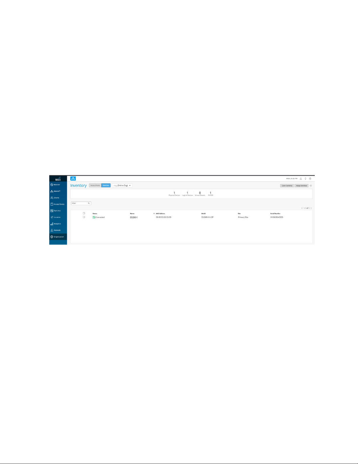
2. Use a Web browser to log in to your Juniper Mist account. The Monitor screen shows an overview of
the Juniper Mist cloud and any connected Juniper access points and clients. Click on Organization >
Inventory in the menu on the left to open the Juniper Mist Inventory Screen.
28
When the ZTP process completes, the switch that you purchased automatically appears in the Inventory
screen. If the switch does not appear after a few minutes, despite refreshing the web page, try logging
out and then logging back in.
Page 29

3. Select Switches at the top of the Inventory screen, and click the Claim Switches button and enter the
activation code for the switch.
29
4. Complete the fields on the screen. Select the Manage configuration with Mist check box and enter a
root password for the switch.
NOTE: When you manage a switch on the Juniper Mist portal, we recommend that you
restrict the usage of the CLI locally on your device to prevent conflicts. At a minimum, you
should create a system login message that displays on the CLI of the switch warning users
not to make configuration changes locally on the switch.
How to Activate a Brownfield Switch
Brownfield switches are switches being brought into the Juniper Mist Cloud from a previous deployment.
We recommend that you back up the existing configuration on the switch before getting started. To
prevent users from using the CLI to configure the switch after it has been adopted into the Juniper Mist
Cloud, you may also want to create a system login message on the switch to warn against making
configuration changes, or you can restrict their management access altogether by changing the password
or placing restrictions on the CLI user accounts.
Page 30

This procedure describes how to set up a secure connection between a supported EX Series switch running
a supported version of Junos OS. Be sure you can log in to both the Juniper Mist portal and the switch
since you will be making configuration changes to both systems.
1. Log in to your organization on Juniper Mist Cloud Click Organization > Inventory to open the Inventory
screen.
2. Select Switches at the top of the Inventory screen and then click Adopt Switches in the upper-right
corner to generate the Junos OS CLI commands needed for the interoperability. The commands create
a Juniper Mist user account and an SSH connection to the Juniper Mist Cloud over TCP port 2200
(This is the switch port connection for a management interface and is used for configuration settings
and sending telemetry data).
30
3. In the window that appears, click Copy to Clipboard to get the commands from the Juniper Mist Cloud.
Page 31

4. On the console of the switch, type configuration to enter configuration mode and then paste the
commands you just copied (type top if you are not already at the base level of the hierarchy).
5. On the Juniper Mist portal, click Organization > Inventory > Switches and select the switch you just
added.
6. Click the More drop-down list at the top of the screen, and then click Assign to Site to continue making
your selections as prompted.
7. Confirm your connection from the switch to the Juniper Mist Cloud in the Junos CLI by typing show
system connections.
user@host> show system connections | grep 2200
tcp4 0 0 10.10.70.89.63208 <ip-address>.2200 ESTABLISHED
The output shows that the switch established a connection to the Juniper Mist Cloud. It includes the
IP Address of the management interface, the IP address of the Juniper Mist Cloud and the connection
status.
31
Troubleshooting
Purpose
The command output shows the switch connection to the Juniper Mist Cloud. It includes the IP address
of the management interface on the switch, the destination IP address of the Juniper Mist Cloud, and the
connection result.
tcp4 0 0 10.10.70.89.63208 <ip-address>.2200 ESTABLISHED
Action
Confirm your connection from the switch to the Juniper Mist Cloud by running the Junos OS command
shown below on your switch console.
user@host> show system connections | grep 2200
If you do not see the switch in the Inventory list, the SRX may be blocking the acknowledgment messages
for the initial connection request. If the SRX is blocking the inbound packets over TCP port 2200, add a
firewall rule to enable communication on port 2200. The switch will appear in Organization > Inventory
> Switches.
Page 32

Day 1: Use a Template-Based Configuration with Device and Port Profile
g301242
Mist AP ge-0/0/0-10 10, 11, 12
IOT Devices ge-0/0/11-14 20
Camera ge-0/0/15-18 30
Access Ports ge-0/0/19-20 40
Uplink ge-0/0/0 Trunk
Switch Management ge-0/0/23 99
Devices Ports VLAN
Mist AP
Mist AP
AI-Driven Cloud
Public IP Address
ge-0/0/15ge-0/0/9
ge-0/0/0
ge-0/0/10 ge-0/0/11
A key feature of switch management through the Juniper Mist Cloud is the ability to use configuration
templates and a hierarchical model to group switches and to make bulk updates. Using templates allows
you to have consistent configurations across the organization and to conveniently apply them to a particular
switch and at scale across your network.
You can create a template configuration and then apply those settings to all the devices in a group. When
a conflict occurs, the more narrow settings override the broader settings. For example, when there are
settings at both the branch and organizational levels that apply to the same device, the more narrow
settings (in this case, branch) override the broader settings that are defined at the organization level.
Figure 6: Network Behind the SRX Device
32
The following procedure configures the EX switch with the network example behind the SRX. The switches
here were on-boarded using the brownfield method with only a minimal management configuration to
access the Internet.
Start by defining the standard configurations that will be used for all the switches in the branch, using the
Switch Configuration template.
1. To create a Configuration template, click Organization > Switch Template in the menu on the left.
Click a headings (All Switches Configuration, Shared Elements, or Select Switches Configuration) to
expand the configuration, and the down arrow to collapse the configuration.
a. Under All Switches Configuration, add the following:
Under RADIUS, add a RADIUS server for the organization or site.
•
Page 33

Under NTP, add the NTP server for the organization or site.
•
Under CLI Configuration, apply any necessary additional configuration parameters such as a
•
corporate login banner, corporate SNMP or syslog servers and so on.
33
b. Under Shared Elements, add the following:
Under Networks, add the following VLANs for the campus:
•
vlan10 (Corp)
•
vlan20 (Guest)
•
vlan30 (IoT)
•
vlan40 (Cameras)
•
vlan99 (Restricted)
•
Under Port Profiles, create the new port profiles for uplink ports such as wan-uplink and
•
switch-uplink for the related ports, and map the port profiles to trunk the above VLANs. vlan99,
which is only locally significant, is an exception.
Under Port Profiles, create the new port profiles for device facing ports such as wifi_ap, cameras,
•
and corp. for the related port and map the port profiles to the above VLANs.
Under Dynamic Port Configuration, create a rule that assigns the port profile mist_ap to Juniper
•
access points automatically. The rule we are creating uses LLDP to detect the chassis ID. For
Page 34

devices with the MAC address of a Juniper access point, the Juniper access point profile is assigned
(shown as xx-xx-xx in the following image:
34
c. Under Select Switches Configurations, add rules for distribution and access layer switch roles:
Under Port Configuration Rules, define the port configuration rules and map the port profiles to
•
the physical ports in the switch. Create a rule to associate the port profile with your switches, in
the example we create rules for an EX4650 virtual chassis with the role of distribution-vc and an
EX3400 virtual chassis switch with a role of access-vc2.
Page 35
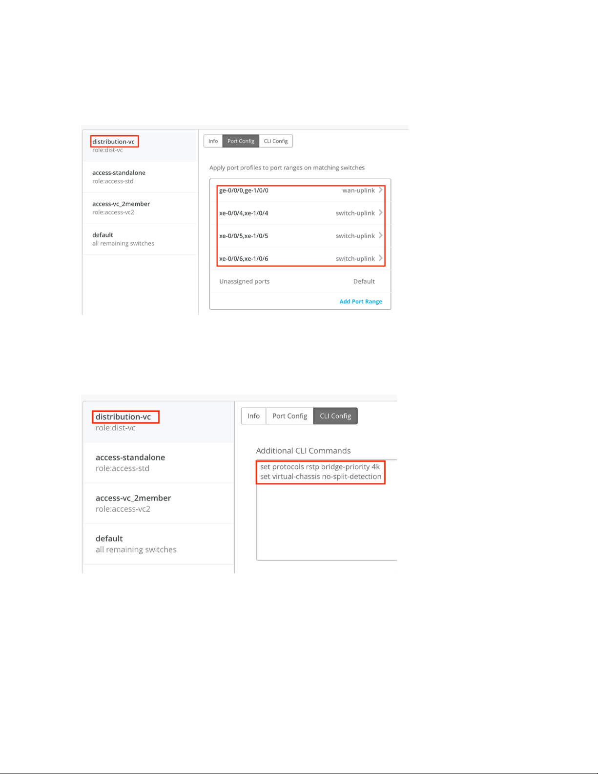
Map the uplink port profiles to physical ports on the distribution switch, as shown in the following
•
image:
35
Include any additional configurations in the CLI Config box. In this example, because the distribution
•
switch is a two-member virtual chassis, we use the no-split-detection command. To ensure root
bridge election, rstp-bridge-priority is set to 4k, as shown in the following image:
Page 36

Repeat the steps to build rules for the access switch, as shown in the following image:
•
On the Port Config screen, map the port profiles to physical ports in the switch:
•
36
Page 37

Next, enable the dynamic port profile assignment by mapping the switch port to a restricted_device
•
profile. This maps a port profile to a VLAN with restricted access and enables Dynamic
Configuration, as is shown in the following image:
37
Page 38

In the CLI config box, you can Include any additional Junos configuration code you may have. In
•
the current example, as previously noted, no-split-detection is set because the access switch is
a two-member virtual chassis:
38
TIP: You can set Junos configurations that are not represented in the Juniper Mist portal, by
including the statements in the CLI configuration text box.
2. Now that the configuration template is set up, you can map the template you just created to your site.
In the main menu, click Network > Switch Configuration and then select the check box next to your
Page 39
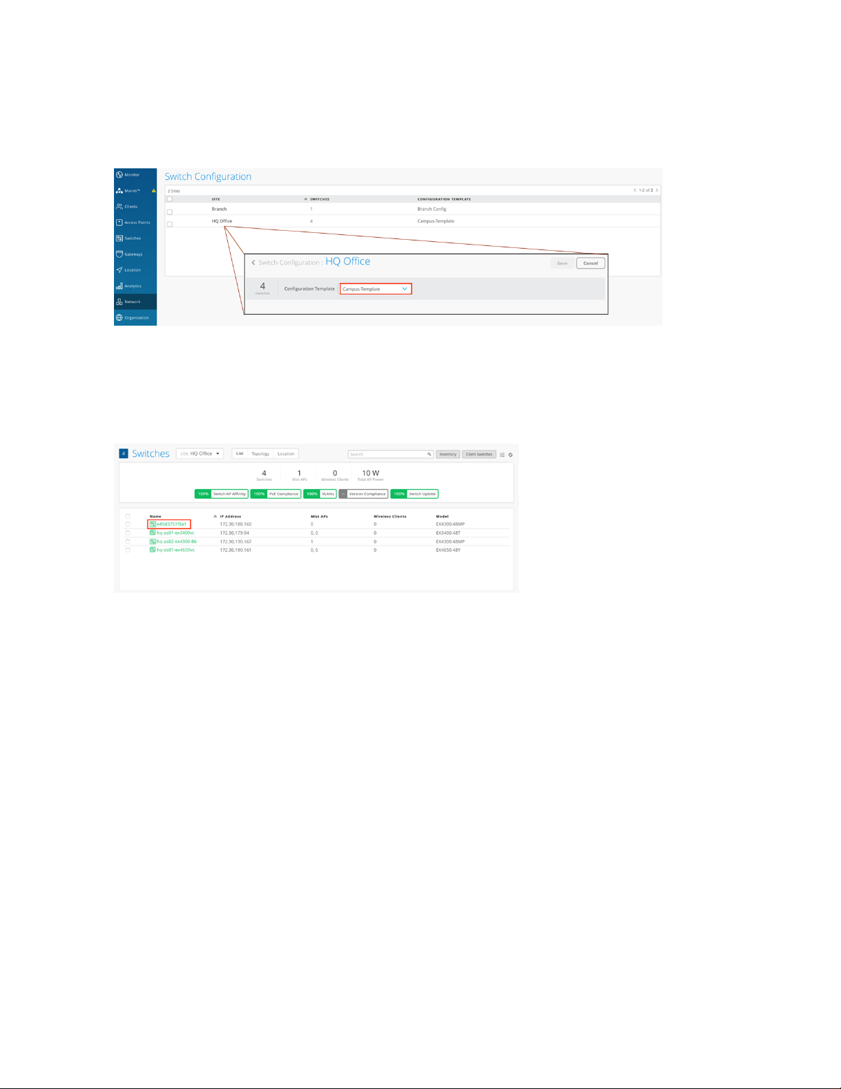
site. Click the Assign to Template link to map the template (here, Campus-Template) to your site, as
shown in the following image:
3. Next we need to apply configuration rules to any devices that have been recently added to the Juniper
Mist portal. To do so, click Switches in the menu and, for this example, select HQ site from the drop
down. A list of devices assigned to that site appears, as shown in the following image:
39
Page 40

4. For this example, one switch remains to be configured, as shown in the following image. Click the switch
name to open the configuration page, and then set a hostname.
40
5. Because the switch is already a member of the Org group, it inherits global configuration settings
defined at that level. These include the Radius and NTP servers we configured in step 1, and the
networks we defined in step 2.
By assigning an existing role to the switch, the switch will also inherit those setting as defined in the
template (you can see this by typing different role names in the Role field). For this example, since the
switch is a standalone access switch, choose the role access-std, as shown in the following image:
Page 41

6. By default IP address assignments are managed by a DHCP server (and Juniper recommends that you
use this option), but you can specify a particular IP address or range of IP addresses by editing the fields
shown in the following image:
41
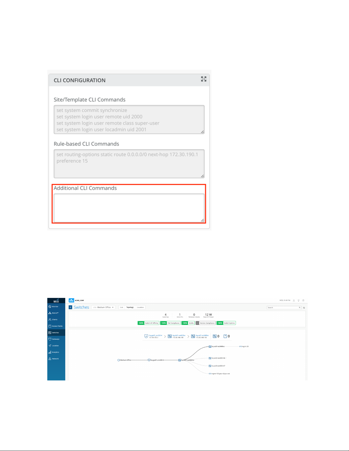
7. You can also add any additional Junos CLI commands that you want to run by including them to the
Additional CLI Commands field, as shown in the following image. (Note that these CLI commands are
Page 42
only applied to the specific switch; they are not part of a template and so will not be inheritable by
other switches.)
42
8. Click Save in the top right of the screen to apply the configuration to the switch. Repeat steps 6 through
9 for any remaining switches.
9. To confirm that the switches have been added to the topology as expected, click Switches on the main
menu, and then Topology to display an interactive list of the configured switches.
Page 43

Wireless Configuration on the Juniper Mist Cloud
Juniper Mist Wi-Fi Assurance, driven by machine learning on Juniper Mist, replaces manual troubleshooting
tasks with automated Wi-Fi (also called wireless, and WLAN) operations. This subscription service makes
Wi-Fi predictable, reliable, and measurable with unique visibility into user service levels. You can set up
and track service-level thresholds for key wireless criteria connection metrics, such as time to connect,
capacity, coverage, and throughput.
In the example below, we create a Wi-Fi template that includes the SSIDs needed for a branch office site.
Templates are handy because they contain all the configuration settings you need for a given location,
and provide an easy, uniform way to apply them.
Once the template has been defined, we will then claim any Juniper Access Points that are deployed at
the site to include it the Juniper Mist portal. The APs need to be physically deployed at site and connected
to the EX switch. Each Juniper Access Point has an AP claim code (Activation code), that you can use to
add it to a site, and thus bring it under management by the Juniper Mist portal. From the Juniper Mist
portal, you navigate to the switch and "claim" the AP so that its location and relationship to switch are
understood by the Juniper Mist portal. Claiming the AP also assigns it to a particular site so you can manage
it, in conjunction with any other APs in the same location, as a part of the site.
43
In the steps below, you will create a site template, and then claim APs to which the configuration settings
defined in the template will apply.
1. To create a template, click Organization > Config Templates in the menu on the left.
2. For this example, we want to create a WLAN template that can be applied to the entire organization,
so give the template a name, and select Entire Org as shown in the following image:
Page 44

3. Configure the Wi-Fi settings as shown in the following image (that is, select WPA-2/EAP (802.1x) for
Security, specify the IP address of your RADIUS server, and specify Untagged as the supported VLAN
type):
44
Page 45
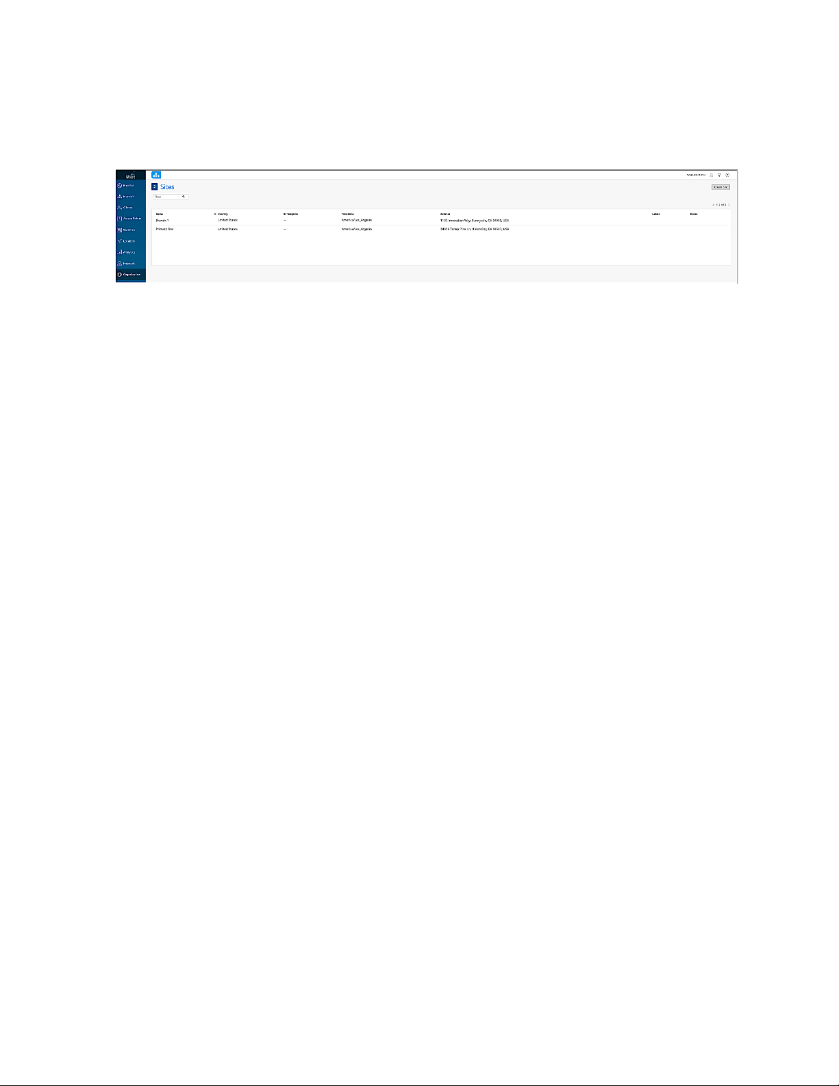
4. Next, we’ll create a site called Branch-1. Click Organization >Site Configuration in the menu, and then
Create Site.
45
Page 46
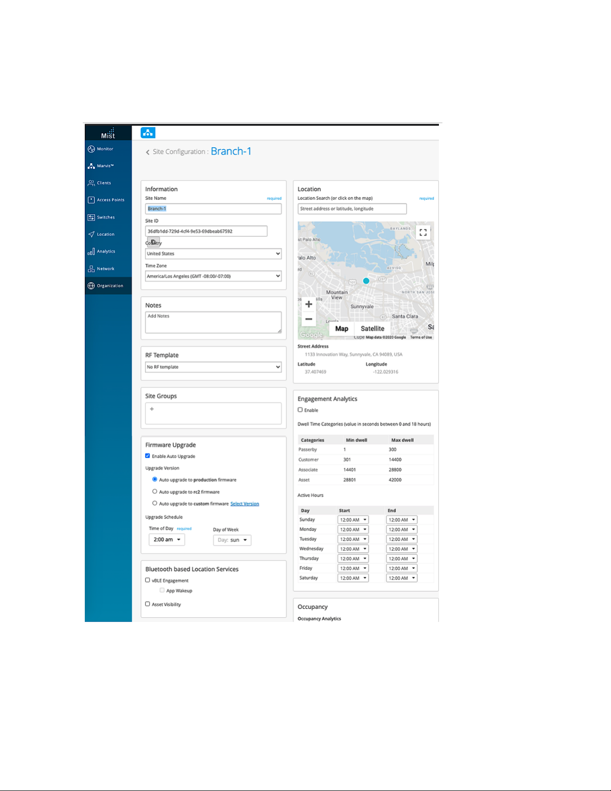
5. In the screen that appears, fill out the settings as appropriate and then when done, click Save at the
top of the page.
46
6. To claim one or more Juniper Access Points (that is, to include the AP as a member of the Branch-1
site, click Access point in the main menu. A list of eligible access points reporting in to the Juniper Mist
portal (through the EX switch we configured) appears on the page.
Page 47

7. Click the Claim APs button at the top of the page, and then enter the Claim Code for one of the Juniper
Access Points deployed at the site. (From the same page you can also select the site to which the AP
belongs (Branch-1, in the current example), give the AP a name, and attach to the AP an AP profile
with additional settings if you like.)
8. Click the Claim button at the bottom of the page to assign the AP to the site and make it available to
the Juniper Mist portal.
47
Page 48

Additional SSID Configuration
Midsize branch offices often require multiple SSIDs and WLANs to control access and security on the
basis of user groups. With Juniper Mist, this can be easily handled by creating multiple VLANs, each with
different access profiles and/or security settings, to support the various profiles.
Recall that in an earlier procedure, we configured a switch port on the SRX as a trunk port with native-vlan-id
enabled for the management of the access points. Now, in the procedure below, we update the branch
site to include WLAN networks for both guest access and for IoT device connections.
1. To edit the template for the branch office, click Organization > Config Templates in the menu.
48
2. Click Add WLAN to create a WLAN with an SSID for guest access on VLAN20, and then Tagged to
assign the VLAN ID.
Page 49

49
Page 50

3. In the Guest Portal work area, click Custom guest portal to customize a WLAN for guest access.
50
4. Enter a name the SSID (here, Branch-IoT), and enable PSK with passphrase security as shown in the
following image. Also assign VLAN ID (30, in this example) and select Untagged.
Page 51

51
Page 52

Repeat the procedure above to set up any other WLANs you want. When you are done, you can view
the list of configured WLANs, as shown in the following image:
Both the EX switch and the access points are now configured and accessible from the Juniper Mist
portal.
52
Conclusion
The Midsize Campus solution reference architecture provides a solid foundation for baseline campus
design for the medium to large campus. The architecture was validated against application RPMs and
tested at scale to include Layer 2 and Layer 3 design, security, QoS, HA, and scale-up to 10,000 users and
40,000 devices (both real and simulated devices). In addition, the solution includes wireless access as well
as policy and identity capabilities necessary for BYOD strategies for today’s mobile enterprise.
 Loading...