

Page 1

Media Flow Manager
Administrator’s Guide and CLI Command Reference
Release
2.0.2
Published: 2010-6-17
Copyright © 2010, Juniper Networks, Inc.
Page 2

Media Flow Manager Administrator’s Guide
Juniper Networks, the Juniper Networks logo, JUNOS, NetScreen, ScreenOS, and SteelBelted Radius are registered trademarks of Juniper Networks, Inc. in the United States and
other countries. JUNOSe is a trademark of Juniper Networks, Inc. All other trademarks,
service marks, registered trademarks, or registered service marks are the property of their
respective owners.
Juniper Networks assumes no responsibility for any inaccuracies in this document. Juniper
Networks reserves the right to change, modify, transfer, or otherwise revise this publication
without notice.
Products made or sold by Juniper Networks or components thereof might be covered by one
or more of the following patents that are owned by or licensed to Juniper Networks: U.S.
Patent Nos. 5,473,599, 5,905,725, 5,909,440, 6,192,051, 6,333,650, 6,359,479, 6,406,312,
6,429,706, 6,459,579, 6,493,347, 6,538,518, 6,538,899, 6,552,918, 6,567,902, 6,578,186,
and 6,590,785.
II Copyright © 2010, Juniper Networks, Inc.
Page 3

Media Flow Manager Administrator’s Guide
End User License Agreement
READ THIS END USER LICENSE AGREEMENT (“AGREEMENT”) BEFORE DOWNLOADING, INSTALLING, OR USING THE SOFTWARE. BY
DOWNLOADING, INSTALLING, OR USING THE SOFTWARE OR OTHERWISE EXPRESSING YOUR AGREEMENT TO THE TERMS CONTAINED
HEREIN, YOU (AS CUSTOMER OR IF YOU ARE NOT THE CUSTOMER, AS A REPRESENTATIVE/AGENT AUTHORIZED TO BIND THE CUSTOMER)
CONSENT TO BE BOUND BY THIS AGREEMENT. IF YOU DO NOT OR CANNOT AGREE TO THE TERMS CONTAINED HEREIN, THEN (A) DO NOT
DOWNLOAD, INSTALL, OR USE THE SOFTWARE, AND (B) YOU MAY CONTACT JUNIPER NETWORKS REGARDING LICENSE TERMS.
1. The Parties. The parties to this Agreement are (i) Juniper Networks, Inc. (if the Customer’s principal office is located in the Americas) or Juniper Networks
(Cayman) Limited (if the Customer’s principal office is located outside the Americas) (such applicable entity being referred to herein as “Juniper”), and (ii) the
person or organization that originally purchased from Juniper or an authorized Juniper reseller the applicable license(s) for use of the Software (“Customer”)
(collectively, the “Parties”).
2. The Software. In this Agreement, “Software” means the program modules and features of the Juniper or Juniper-supplied software, for which Customer has paid
the applicable license or support fees to Juniper or an authorized Juniper reseller, or which was embedded by Juniper in equipment which Customer purch as ed
from Juniper or an authorized Juniper reseller. “Software” also includes updates, upgrades and new releases of such software. “Embedded Software” means
Software which Juniper has embedded in or loaded onto the Juniper equipment and any updates, upgrades, additions or replacements which are subsequently
embedded in or loaded onto the equipment.
3. License Grant. Subject to payment of the applicable fees and the limitations and restrictions set forth herein, Juniper grants to Customer a non-exclusive and
non-transferable license, without right to sublicense, to use the Software, in executable form only, subject to the following use restrictions:
a. Customer shall use Embedded Software solely as embedded in, and for execution on, Juniper equipment originally purchased by Customer from Juniper or
an authorized Juniper reseller.
b. Customer shall use the Software on a single hardware chassis having a single processing unit, or as many chassis or processing units for which Customer
has paid the applicable license fees; provided, however, with respect to the Steel-Belted Radius or Odyssey Access Client software only, Customer shall
use such Software on a single computer containing a single physical random access memory space and containing any number of processors. Use of the
Steel-Belted Radius or IMS AAA software on multiple computers or virtual machines (e.g., Solaris zones) requires multiple licenses, regardless of whether
such computers or virtualizations are physically contained on a single chassis.
c. Product purchase documents, paper or electronic user documentation, and/or the particular licenses purchased by Customer may specify limits to
Customer’s use of the Software. Such limits may restrict use to a maximum number of seats, registered endpoints, concurrent users, sessions, calls,
connections, subscribers, clusters, nodes, realms, devices, links, ports or transactions, or require the purchase of separate licenses to use particular features,
functionalities, services, applications, operations, or capabilities, or provide throughput, performance, configuration, bandwidth, interface, processing,
temporal, or geographical limits. In addition, such limits may restrict the use of the Software to managing certain kinds of networks or require the Software
to be used only in conjunction with other specific Software. Customer’s use of the Software shall be subject to all such limitations and purchase of all
applicable licenses.
d. For any trial copy of the Software, Customer’s right to use the Software expires 30 days after download, installation or use of the Software. Customer may
operate the Software after the 30-day trial period only if Customer pays for a license to do so. Customer may not extend or create an additional trial period
by re-installing the Software after the 30-day trial period.
e. The Global Enterprise Edition of the Steel-Belted Radius software may be used by Customer only to manage access to Customer’s enterprise network.
Specifically, service provider customers are expressly prohibited from using the Global Enterprise Edition of the Steel-Belted Radius software to support
any commercial network access services.
The foregoing license is not transferable or assignable by Customer. No license is granted herein to any user who did not originally purchase the applicable
license(s) for the Software from Juniper or an authorized Juniper reseller.
4. Use Prohibitions. Notwithstanding the foregoing, the license provided herein does not permit the Customer to, and Customer agrees not to and shall not: (a)
modify, unbundle, reverse engineer, or create derivative works based on the Software; (b) make unauthorized copies of the Software (except as necessary for
backup purposes); (c) rent, sell, transfer, or grant any rights in and to any copy of the Software, in any form, to any third party; (d) remove any proprietary notices,
labels, or marks on or in any copy of the Software or any product in which the Software is embedded; (e) distribute any copy of the Software to any third party,
including as may be embedded in Juniper equipment sold in the secondhand market; (f) use any ‘locked’ or key-restricted feature, function, service, application,
operation, or capability without first purchasing the applicable license(s) and obtaining a valid key from Juniper, even if such feature, function, service,
application, operation, or capability is enabled without a key; (g) distribute any key for the Software provided by Juniper to any third party; (h) use the Software
in any manner that extends or is broader than the uses purchased by Customer from Juniper or an authorized Juniper reseller; (i) use Embedded Software on nonJuniper equipment; (j) use Embedded Software (or make it available for use) on Juniper equipment that the Customer did not originally purchase from Juniper or
an authorized Juniper reseller; (k) disclose the results of testing or benchmarking of the Software to any third party without the prior written consent of Juniper;
or (l) use the Software in any manner other than as expressly provided herein.
5. Audit. Customer shall maintain accurate records as necessary to verify compliance with this Agreement. Upon request by Juniper, Customer shall furnish such
records to Juniper and certify its compliance with this Agreement.
6. Confidentiality. The Parties agree that aspects of the Software and associated documentation are the confidential property of Juniper. As such, Customer shall
exercise all reasonable commercial ef forts t o mai nta in t he Soft ware a nd associat e d docume ntati on in conf idence , which at a mini mum i ncludes res tri cti ng acce ss
to the Software to Customer employees and contractors having a need to use the Software for Customer’s internal business purposes.
7. Ownership. Juniper and Juniper’s licensors, respectively , retain ownership of all right, title, and interest (including copyright) in and to the Software, associated
documentation, and all copies of the Software. Nothing in this Agreement constitutes a transfer or conveyance of any right, title, or interest in the Software or
associated documentation, or a sale of the Software, associated documentation, or copies of the Software.
8. Warranty, Limitation of Liability, Disclaimer of Warranty. The warranty applicable to the Software shall be as set forth in the warranty statement that
accompanies the Software (the “Warranty Statement”). Nothing in this Agreement shall give rise to any obligation to support the Software. Support services may
be purchased separately. Any such support shall be governed by a separate, written support services agreement. TO THE MAXIMUM EXTENT PERMITTED
BY LAW, JUNIPER SHALL NOT BE LIABLE FOR ANY LOST PROFITS, LOSS OF DATA, OR COSTS OR PROCUREMENT OF SUBSTITUTE GOODS
III
Page 4

Media Flow Manager Administrator’s Guide
OR SERVICES, OR FOR ANY SPECIAL, INDIRECT, OR CONSEQUENTIAL DAMAGES ARISING OUT OF THIS AGREEMENT, THE SOFTWARE, OR
ANY JUNIPER OR JUNIPER-SUPPLIED SOFTWARE. IN NO EVENT SHALL JUNIPER BE LIABLE FOR DAMAGES ARISING FROM
UNAUTHORIZED OR IMPROPER USE OF ANY JUNIPER OR JUNIPER-SUPPLIED SOFTWARE. EXCEPT AS EXPRESSLY PROVIDED IN THE
WARRANTY STATEMENT TO THE EXTENT PERMITTED BY LAW, JUNIPER DISCLAIMS ANY AND ALL WARRANTIES IN AND TO THE
SOFTWARE (WHETHER EXPRESS, IMPLIED, STATUTORY, OR OTHERWISE), INCLUDING ANY IMPLIED WARRANTY OF MERCHANTABILITY,
FITNESS FOR A PARTICULAR PURPOSE, OR NONINFRINGEMENT. IN NO EVENT DOES JUNIPER WARRANT THAT THE SOFTWARE, OR ANY
EQUIPMENT OR NETWORK RUNNING THE SOFTWARE, WILL OPERATE WITHOUT ERROR OR INTERRUPTION, OR WILL BE FREE OF
VULNERABILITY TO INTRUSION OR ATTACK. In no event shall Juniper’s or its suppliers’ or licensors’ liability to Customer, whether in contract, tort
(including negligence), breach of warranty, or otherwise, exceed the price paid by Customer for the Software that gave rise to the claim, or if the Software is
embedded in another Juniper product, the price paid by Customer for such other product. Customer acknowledges and agrees that Juniper has set its prices and
entered into this Agreement in reliance upon the disclaimers of warranty and the limitations of liability set forth herein, that the same reflect an allocation of risk
between the Parties (including the risk that a contract remedy may fail of its essential purpose and cause consequential loss), and that the same form an essential
basis of the bargain between the Parties.
9. Termination. Any breach of this Agreement or failure by Customer to pay any applicable fees due shall result in automatic termination of the license granted
herein. Upon such termination, Customer shall destroy or return to Juniper all copies of the Software and related documentatio n in Customer’s possession or
control.
10. Taxes. All license fees payable under this agreement are exclusive of tax. Customer shall be responsible for paying Taxes arising from the purchase of the
license, or importation or use of the Software. If applicable, valid exemption documentation for each taxing jurisdiction shall be provided to Juniper prior to
invoicing, and Customer shall promptly notify Juniper if their exemption is revoked or modified. All payments made by Customer shall be net of any applicable
withholding tax. Customer will provide reasonable assistance to Juniper in connection with such withholding taxes by promptly: providing Juniper with valid
tax receipts and other required documentation showing Customer’s payment of any withholding taxes; completing appropriate applications that would reduce the
amount of withholding tax to be paid; and notifying and assisting Juniper in any audit or tax proceeding related to transactions hereunder. Customer shall comply
with all applicable tax laws and regulations, and Customer will promptly pay or reimburse Juniper for all costs and damages related to any liability incurred by
Juniper as a result of Customer’s non-compliance or delay with its responsibilities herein. Customer’s obligations under this Section shall survive termination or
expiration of this Agreement.
11. Export. Customer agrees to comply with all applicable export laws and restrictions and regulations of any United States and any applicable foreign agency or
authority, and not to export or re-export the Software or any direct product thereof in violation of any such restrictions, laws or regulations, or without all
necessary approvals. Customer shall be liable for any such violations. The version of the Software supplied to Customer may contain encryption or other
capabilities restricting Customer’s ability to export the Software without an export license.
12. Commercial Computer Software. The Software is “commercial computer software” and is provided with restricted rights. Use, duplication, or disclosure by
the United States government is subject to restrictions set forth in this Agreement and as provided in DFARS 227.7201 through 227.7202-4, FAR 12.212, FAR
27.405(b)(2), FAR 52.227-19, or FAR 52.227-14(ALT III) as applicable.
13. Interface Information. To the extent required by applicable law, and at Customer's written request, Juniper shall provide Customer with the interfac
information needed to achieve interoperability between the Software and another independently created program, on payment of applicable fee, if any. Customer
shall observe strict obligations of confidentiality with respect to such information and shall use such information in compliance with any applicable terms and
conditions upon which Juniper makes such information available.
14. Third Party Software. Any licensor of Juniper whose software is embedded in the Software and any supplier of Juniper whose products or technology are
embedded in (or services are accessed by) the Software shall be a third party beneficiary with respect to this Agreement, and such licensor or vendor shall have
the right to enforce this Agreement in its own name as if it were Juniper. In addition, certain third party software may be provided with the Software and is subject
to the accompanying license(s), if any, of its respective owner(s). To the extent portions of the Software are distributed under and subject to open source licenses
obligating Juniper to make the source code for such portions publicly available (such as the GNU General Public License (“GPL”) or the GNU Library General
Public License (“LGPL”)), Juniper will make such source code portions (including Juniper modifications, as appropriate) available upon request for a period of
up to three years from the date of distribution. Such request can be made in writing to Juniper Networks, Inc., 1194 N. Mathilda Ave., Sunnyvale, CA 94089,
ATTN: General Counsel. You may obtain a copy of the GPL at http://www.gnu.org/licenses/gpl.html, and a copy of the LGPL at http://www.gnu.org/licenses/
lgpl.html.
15. Miscellaneous. This Agreement shall be governed by the laws of the State of California without reference to its conflicts of laws principles. The provisions of
the U.N. Convention for the International Sale of Goods shall not apply to this Agreement. For any disputes arising under this Agreement, the Parties hereby
consent to the personal and exclusive jurisdiction of, and venue in, the state and federal courts within Santa Clara County, California. This Agreement constitutes
the entire and sole agreement between Juniper and the Customer wi th respec t t o the S oftwar e, and supersedes all prior and contemporaneous agreements relat ing
to the Software, whether oral or written (including any inconsistent terms contained in a purchase order), except that the terms of a separate written agreement
executed by an authorized Juniper representative and Customer shall govern to the extent such terms are inconsistent or conflict with terms contained herein. No
modification to this Agreement nor any waiver of any rights hereunder shall be effective unless expressly assented to in writing by the party to be charged. If any
portion of this Agreement is held invalid, the Parties agree that such invalidity shall not affect the validity of the remainder of this Agreement. This Agreement
and associated documentation has been written in the English language, and the Parties agree that the English version will govern. (For Canada: Les parties aux
présentés confirment leur volonté que cette convention de même que tous les documents y compris tout avis qui s'y rattaché, soient redigés en langue anglaise.
(Translation: The parties confirm that this Agreement and all related documentation is and will be in the English language)).
e
IV Copyright © 2010, Juniper Networks, Inc.
Page 5

Media Flow Manager Administrator’s Guide
Document History
Date Media Flow Manager Version Comments
2010-4-27 Release 2.0 Document Version 2.0
2010-6-17 Release 2.0 Document Version 2.0a
V
Page 6

Media Flow Manager Administrator’s Guide
VI Copyright © 2010, Juniper Networks, Inc.
Page 7

TABLE OF CONTENTS
End User License Agreement ..................................................................... III
Document History ........................................................................................V
1
Preface ................................................................................................... 1.19
Guide to This Document ............................................................................................. 1.19
Documentation and Release Notes ............................................................................ 1.19
Typographical Conventions ........................................................................................ 1.20
Terminology ................................................................................................................ 1.20
Documentation Feedback ........................................................................................... 1.21
Requesting Technical Support.................................................................................... 1.22
Self-Help Online Tools and Resources .............................................................................. 1.22
Opening a Case with JTAC ................................................................................................ 1.23
2
Media Flow Manager Overview ............................................................. 2.25
Remote Monitoring and Management ................................................................................ 2.26
Fault Management.............................................................................................................. 2.26
Groups and Profiles............................................................................................................ 2.26
Central Management Console .................................................................................... 2.27
Appliances (Media Flow Controllers).................................................................................. 2.27
Groups................................................................................................................................ 2.27
Identities ............................................................................................................................. 2.28
Profiles................................................................................................................................ 2.28
Status Criteria..................................................................................................................... 2.28
Rendezvous........................................................................................................................ 2.28
Service Director .......................................................................................................... 2.29
Admission Control....................................................................................................... 2.30
Real-Time Log File Analyzer....................................................................................... 2.30
Copyright © 2010, Juniper Networks, Inc. VII
Page 8

TABLE OF CONTENTS Media Flow Manager Administrator’s Guide
3
Media Flow Manager Web-Based Interface ........................................... 3.33
First Time Login .......................................................................................................... 3.34
Monitoring ................................................................................................................... 3.34
Monitoring > Summary ....................................................................................................... 3.34
Monitoring > CMC Media Flow Controllers......................................................................... 3.35
Monitoring > CPU Load ...................................................................................................... 3.38
Monitoring > Memory.......................................................................................................... 3.38
Monitoring > Network ......................................................................................................... 3.38
Monitoring > File System.................................................................................................... 3.39
System Config............................................................................................................. 3.39
System Config > Interfaces ................................................................................................ 3.39
System Config > Routing.................................................................................................... 3.41
System Config > DNS ........................................................................................................ 3.42
System Config > Hostname................................................................................................ 3.43
System Config > Hosts....................................................................................................... 3.44
System Config > ARP (Address Resolution)...................................................................... 3.44
System Config > Web......................................................................................................... 3.46
System Config > Users....................................................................................................... 3.48
System Config > SSH......................................................................................................... 3.50
System Config > AAA (authentication)............................................................................... 3.50
System Config > RADIUS .................................................................................................. 3.51
System Config > TACACS+ ............................................................................................... 3.53
System Config > SNMP...................................................................................................... 3.55
System Config > Faults ...................................................................................................... 3.57
System Config > Logging ................................................................................................... 3.59
System Config > Configurations......................................................................................... 3.61
System Config > Date and Time ........................................................................................ 3.63
System Config > NTP......................................................................................................... 3.64
System Config > Licensing................................................................................................. 3.65
System Config > Reboot .................................................................................................... 3.66
System Config > Upgrade .................................................................................................. 3.66
CMC Setup ................................................................................................................. 3.68
CMC Setup > Media Flow Controllers ................................................................................ 3.68
CMC Setup > Groups ......................................................................................................... 3.71
CMC Setup > Identities ...................................................................................................... 3.71
CMC Setup > Rendezvous................................................................................................. 3.73
CMC Profiles............................................................................................................... 3.74
Manage Profiles.................................................................................................................. 3.74
Create Profiles.................................................................................................................... 3.74
CMC Profiles > Apply Profile .............................................................................................. 3.75
CMC Profiles > Edit Profile................................................................................................. 3.76
VIII Copyright © 2010, Juniper Networks, Inc.
Page 9

Media Flow Manager Administrator’s Guide TABLE OF CONTENTS
Preset Profiles............................................................................................................. 3.79
Preset Profiles > Preset Actions......................................................................................... 3.79
Preset Profiles > Preset Config .......................................................................................... 3.81
Service Director .......................................................................................................... 3.82
Configure Service Director ................................................................................................. 3.83
Admission Control....................................................................................................... 3.86
Media Flow Controller(s) Transmit Bandwidth.................................................................... 3.86
Admission Control > Configure........................................................................................... 3.87
View Logs ................................................................................................................... 3.89
Reports ....................................................................................................................... 3.89
4
About the Command Line Interface (CLI) .............................................. 4.93
Connecting and Logging In......................................................................................... 4.93
Command Modes ............................................................................................................... 4.93
Command Conventions .............................................................................................. 4.94
Prompt and Response Conventions................................................................................... 4.94
Command Syntax Notation Conventions............................................................................ 4.95
Command Arguments Key.......................................................................................... 4.95
CLI Options................................................................................................................. 4.96
5
CLI Commands ..................................................................................... 5.99
aaa............................................................................................................................ 5.101
aaa (authentication).......................................................................................................... 5.101
aaa (authorization)............................................................................................................ 5.101
arp.............................................................................................................................5.102
banner....................................................................................................................... 5.102
boot........................................................................................................................... 5.102
clear .......................................................................................................................... 5.103
cli............................................................................................................................... 5.103
clock.......................................................................................................................... 5.103
cmc ........................................................................................................................... 5.104
cmc appliance...................................................................................................................5.104
cmc auth........................................................................................................................... 5.106
cmc group......................................................................................................................... 5.107
cmc profile ........................................................................................................................ 5.108
IX
Page 10

TABLE OF CONTENTS Media Flow Manager Administrator’s Guide
cmc rendezvous ............................................................................................................... 5.109
cmc server........................................................................................................................ 5.110
cmc status ........................................................................................................................ 5.110
configuration ............................................................................................................. 5.111
configuration text ..............................................................................................................5.113
configure ................................................................................................................... 5.114
crypto ........................................................................................................................ 5.115
debug........................................................................................................................ 5.116
email ......................................................................................................................... 5.116
email event name ............................................................................................................. 5.118
email class........................................................................................................................ 5.119
enable ....................................................................................................................... 5.119
exit ............................................................................................................................5.119
file ............................................................................................................................. 5.120
ftp-server................................................................................................................... 5.121
hostname .................................................................................................................. 5.121
image ........................................................................................................................ 5.121
interface .................................................................................................................... 5.122
ip ............................................................................................................................... 5.123
job .............................................................................................................................5.124
license....................................................................................................................... 5.126
logging ...................................................................................................................... 5.127
logging severity level ........................................................................................................ 5.129
ntp.............................................................................................................................5.130
ntpdate...................................................................................................................... 5.131
ping ........................................................................................................................... 5.131
radius-server............................................................................................................. 5.131
reload........................................................................................................................ 5.132
reset.......................................................................................................................... 5.133
service-director ......................................................................................................... 5.133
show.......................................................................................................................... 5.135
slogin......................................................................................................................... 5.136
snmp-server.............................................................................................................. 5.136
snmp traps........................................................................................................................ 5.138
snmp traps events ............................................................................................................ 5.138
X Copyright © 2010, Juniper Networks, Inc.
Page 11

Media Flow Manager Administrator’s Guide TABLE OF CONTENTS
ssh ............................................................................................................................ 5.139
ssh client........................................................................................................................... 5.139
ssh server......................................................................................................................... 5.140
stats .......................................................................................................................... 5.141
stats alarms ...................................................................................................................... 5.143
stats CHDs ....................................................................................................................... 5.144
stats samples.................................................................................................................... 5.145
tacacs-server ............................................................................................................ 5.145
tcpdump .................................................................................................................... 5.147
telnet ......................................................................................................................... 5.147
telnet-server.............................................................................................................. 5.147
terminal ..................................................................................................................... 5.147
traceroute.................................................................................................................. 5.147
username.................................................................................................................. 5.147
web ........................................................................................................................... 5.149
web................................................................................................................................... 5.149
web proxy ......................................................................................................................... 5.150
write .......................................................................................................................... 5.151
INDEX .................................................................................................IX.153
XI
Page 12

TABLE OF CONTENTS Media Flow Manager Administrator’s Guide
XII Copyright © 2010, Juniper Networks, Inc.
Page 13

LIST OF FIGURES
Figure 1 Media Flow Manager Interaction .................................................................................. 2.25
Figure 2 How Service Director Works ........................................................................................ 2.29
Figure 3 Media Flow Manager Login Page Detail ...................................................................... 3.33
Figure 4 Monitoring > Summary Page Detail ............................................................................. 3.35
Figure 5 Monitoring -> CMC Media Flow Controllers Page........................................................ 3.36
Figure 6 Monitoring -> CMC Media Flow Controllers Media Flow Controller Detail Window ..... 3.37
Figure 7 Monitoring > CPU Load Graph..................................................................................... 3.38
Figure 8 System Config > Interfaces Page Detail (eth0 configuration) ...................................... 3.40
Figure 9 System Config > Interfaces Page Detail (Add new interface alias) .............................. 3.40
Figure 10 System Config > Routing Page Detail (Default Gateway)............................................ 3.41
Figure 11 System Config > Routing Page Detail (Static and Dynamic Routes) ........................... 3.41
Figure 12 System Config > Routing Page Detail (Add Static Route) ........................................... 3.42
Figure 13 System Config > DNS Page Detail (Add or Modify Name Servers) ............................. 3.42
Figure 14 System Config > DNS Page Detail............................................................................... 3.43
Figure 15 System Config > DNS Page Detail............................................................................... 3.43
Figure 16 System Config > Hostname Page Detail...................................................................... 3.44
Figure 17 System Config > Hosts Page Detail ............................................................................. 3.44
Figure 18 System Config > Hosts Page Detail ............................................................................. 3.44
Figure 19 System Config > ARP Page Detail ............................................................................... 3.45
Figure 20 System Config > ARP Page Detail ............................................................................... 3.45
Figure 21 System Config > ARP Page Detail ............................................................................... 3.46
Figure 22 System Config > Web Page Detail (Web UI Configuration) ......................................... 3.47
Figure 23 System Config > Web Page Detail (Web Proxy Configuration) ................................... 3.48
Figure 24 System Config > Users Page Detail (User Accounts) .................................................. 3.49
Figure 25 System Config > Users Page Detail (Add New User) .................................................. 3.49
Figure 26 System Config > SSH Page Detail ............................................................................... 3.50
Figure 27 System Config > AAA Page Detail ............................................................................... 3.50
Figure 28 System Config > AAA Page Detail ............................................................................... 3.51
Figure 29 System Config > RADIUS Page Detail (Default RADIUS Settings) ............................. 3.52
Figure 30 System Config > RADIUS Page Detail (RADIUS Servers) .......................................... 3.52
Copyright © 2010, Juniper Networks, Inc. XIII
Page 14

LIST OF FIGURES
Figure 31 System Config > RADIUS Page Detail......................................................................... 3.53
Figure 32 System Config > TACACS+ Page Detail (Default TACACS+ Settings) ....................... 3.53
Figure 33 System Config > TACACS+ Page Detail (TACACS+ Servers) .................................... 3.54
Figure 34 System Config > TACACS+ Page Detail...................................................................... 3.55
Figure 35 System Config > SNMP Page Detail (SNMP Configuration)........................................ 3.56
Figure 36 System Config > SNMP Page Detail (Trap Sinks) ....................................................... 3.56
Figure 37 System Config > Faults Page Detail (Fault Reporting) ................................................ 3.57
Figure 38 System Config > Faults Page Detail (Notify Recipients) .............................................. 3.58
Figure 39 System Config > Faults Page Detail (Add New Notify Recipients) .............................. 3.58
Figure 40 System Config > Logging Page Detail (Local Log Filtering)......................................... 3.59
Figure 41 System Config > Logging Page Detail (Local Log Rotation) ........................................ 3.60
Figure 42 System Config > Logging Page Detail (Remote Log Sinks)......................................... 3.60
Figure 43 System Config > Logging Page Detail (Add New Remote Sink) .................................. 3.60
Figure 44 System Config > Logging Page Detail (Log Format).................................................... 3.61
Figure 45 System Config > Configurations Page Detail (Configuration Files List) ....................... 3.61
Figure 46 System Config > Configurations Page Detail (Active Configuration) ........................... 3.62
Figure 47 System Config > Configurations Page Detail (Upload Configuration) .......................... 3.62
Figure 48 System Config > Configurations Page Import Configuration Detail ............................. 3.63
Figure 49 System Config > Date and Time Page Detail............................................................... 3.63
Figure 50 System Config > NTP Page Detail (NTP Setup) .......................................................... 3.64
Figure 51 System Config > NTP Page Detail (NTP Servers) ....................................................... 3.64
Figure 52 System Config > NTP Page Detail (Add New NTP Server) ......................................... 3.65
Figure 53 System Config > License Page Detail (Installed Licenses).......................................... 3.65
Figure 54 System Config > License Page Detail (Add New License(s)) ...................................... 3.66
Figure 55 System Config > Reboot Page Detail........................................................................... 3.66
Figure 56 System Config > Upgrade Page Detail (Installed Images) ........................................... 3.67
Figure 57 System Config > Upgrade Page Detail (Install New Image to Partition N)................... 3.67
Figure 58 CMC Setup Page Detail (Managed Nodes List)........................................................... 3.69
Figure 59 CMC Setup Page (Add New Node).............................................................................. 3.70
Figure 60 CMC Setup > Groups Page Detail ............................................................................... 3.71
Figure 61 CMC Setup > Identities Page....................................................................................... 3.72
Figure 62 CMC Setup > Rendezvous Page Detail ....................................................................... 3.73
Figure 63 CMC Profiles Page (Manage Profiles) ......................................................................... 3.74
Figure 64 CMC Profiles Page....................................................................................................... 3.75
Figure 65 CMC Profiles > Apply Profile Page .............................................................................. 3.76
Figure 66 CMC Profiles > Edit Profile Page Detail (Select Profile) .............................................. 3.77
Figure 67 CMC Profiles > Edit Profile Page Detail (Edit Comment)............................................. 3.77
Figure 68 CMC Profiles > Edit Profile Page Detail (Add Generic Command) .............................. 3.77
XIV Copyright © 2010, Juniper Networks, Inc.
Page 15

LIST OF FIGURES
Figure 69 CMC Profiles > Edit Profile Page Detail (All Commands) ............................................ 3.78
Figure 70 Preset Profiles > Show Namespace Page Detail ......................................................... 3.79
Figure 71 Preset Profiles > Purge Objects Page Detail ............................................................... 3.80
Figure 72 Preset Profiles > Audit Nodes Page Detail................................................................... 3.81
Figure 73 Preset Profiles > Apply Probe Page Detail................................................................... 3.82
Figure 74 Service Director > Configure Page Detail (New Preset XML Response)..................... 3.83
Figure 75 Service Director > Configure Page Detail (New URL Host) ......................................... 3.83
Figure 76 Service Director > Configure Page Detail (Optional Security Configuration) ............... 3.84
Figure 77 Service Director > Configure Page Detail (Match Response Configuration)................ 3.85
Figure 78 Service Director > Configure Page Detail (Manage Service Director) ......................... 3.85
Figure 79 Service Director > Configure Page Detail (Service Director’s crossdomain.xml
Configuration) ................................................................................................................................. 3.86
Figure 80 Admission Control > Configure Page Detail (Configure Control Parameters).............. 3.87
Figure 81 Admission Control > Configure Page Detail (Monitored Nodes List) ........................... 3.88
Figure 82 Admission Control > Configure Page Detail (Add Node to be Monitored) ................... 3.88
Figure 83 CMC View Log Page Detail.......................................................................................... 3.89
Figure 84 CMC Reports Page Detail ............................................................................................ 3.90
XV
Page 16

LIST OF FIGURES
XVI Copyright © 2010, Juniper Networks, Inc.
Page 17

LIST OF SUBJECTS (Web-Based Interface) Media Flow Manager Administrator’s Guide
LIST OF SUBJECTS (Web-Based Interface)
Log Into the System, First Time ..................................................................................................... 3.34
Set DHCP (dynamic host configuration protocol) Primary Interface .............................................. 3.40
Add a New Interface Alias ............................................................................................................. 3.40
Set Default Gateway ...................................................................................................................... 3.41
Add Static Routes .......................................................................................................................... 3.41
Add or Modify Name Servers ......................................................................................................... 3.42
Set System Hostname ................................................................................................................... 3.43
Set Static Host Entries ................................................................................................................... 3.44
Add New Host ................................................................................................................................ 3.44
Add New Static ARP Entry ............................................................................................................ 3.45
Empty the ARP Cache ................................................................................................................... 3.45
Configure the CMC Web-based Interface ...................................................................................... 3.46
Configure the CMC Web-based Proxy .......................................................................................... 3.47
Add a New User ............................................................................................................................. 3.49
Change User Passwords ............................................................................................................... 3.49
Generate Host Keys ...................................................................................................................... 3.50
Set Authentication Methods for System Logins ............................................................................. 3.50
Set Authorization for System Logins .............................................................................................. 3.51
Configure RADIUS Authentication ................................................................................................. 3.51
Configure TACACS+ Authentication .............................................................................................. 3.53
Configure SNMP ............................................................................................................................ 3.55
Configure Fault Reporting .............................................................................................................. 3.57
Configure Logging Options ............................................................................................................ 3.59
Manage Configuration Files ........................................................................................................... 3.61
Upload Configuration Files ............................................................................................................ 3.62
Set System Date and Time ............................................................................................................ 3.63
Configure Network Time Protocol (NTP) ....................................................................................... 3.64
Add or Remove Licenses ............................................................................................................... 3.65
Reboot ........................................................................................................................................... 3.66
Install Upgrades ............................................................................................................................. 3.66
Add Nodes for CMC Management ................................................................................................. 3.68
Create CMC Groups ...................................................................................................................... 3.71
Copyright © 2010, Juniper Networks, Inc. XVII
Page 18

LIST OF SUBJECTS (Web-Based Interface) Media Flow Manager Administrator’s Guide
Create Node Identities CMC Authentication .................................................................................. 3.71
Set CMC Rendezvous Parameters ................................................................................................ 3.73
Create and Manage CMC Profiles .................................................................................................3.74
Apply CMC Profiles ........................................................................................................................ 3.75
Edit CMC Profiles .......................................................................................................................... 3.76
View Node Namespaces ............................................................................................................... 3.79
Purge Node Namespace Objects .................................................................................................. 3.79
Audit Managed Nodes ................................................................................................................... 3.80
Configure Service Director ............................................................................................................. 3.83
Configure Admission Control Parameters ..................................................................................... 3.87
Add Node to Monitoring List .......................................................................................................... 3.88
XVIII Copyright © 2010, Juniper Networks, Inc.
Page 19

CHAPTER 1 Preface Media Flow Manager Administrator’s Guide
CHAPTER 1
Preface
This Administrator’s Guide is written for administrators of Juniper Networks Media Flow
Manager. In addition to the Guide to This Document
these topics:
• Documentation and Release Notes
• Typographical Conventions
• Te rm in ol o gy
• Documentation Feedback
• Requesting Technical Support
section, below, this preface includes
Guide to This Document
This document provides information on the following topics:
• Media Flow Manager Overview—An overview of Media Flow Manager features.
• Media Flow Manager Web-Based Interface—A page-by-page description of the Web-
based interface for Media Flow Manager.
• About the Command Line Interface (CLI)—Describes CMC CLI logging in, command
notation conventions, roles and privileges, terminology, and CLI options.
• CLI Commands—Alphabetical list of all commands including keywords, arguments, and
notes.
Documentation and Release Notes
To obtain the most current version of all Juniper Networks® technical documentation, see the
product documentation page on the Juniper Networks website at
http://www.juniper.net/techpubs/
Juniper Networks supports a technical book program to publish books by Juniper Networks
engineers and subject matter experts with book publishers around the world. These books go
beyond the technical documentation to explore the nuances of network architecture,
deployment, and administration using JUNOS Software and Juniper Networks devices. In
addition, the Juniper Networks Technical Library, published in conjunction with O'Reilly Media,
explores improving network security, reliability, and availability using JUNOS configuration
techniques. All the books are for sale at technical bookstores and book outlets around the
world. The current list can be viewed at http://www.juniper.net/books
.
.
Copyright © 2010, Juniper Networks, Inc. Guide to This Document 19
Page 20

CHAPTER 1 Preface Media Flow Manager Administrator’s Guide
Typographical Conventions
Table 1 describes the typefaces used in this book.
Table 1 Typefaces Used in This Book
Typeface Use Example
Arial Ordinary text. The origin server organizes media
content hierarchically.
Arial Bold Commands in running text, and
Arial Italic Book titles, and emphasis. See the Juniper Networks Media
Courier New
Courier New
Bold
Terminology
This section provides definitions for Juniper Networks and industry-standard terms that may
be unfamiliar to the reader.
AFR Assured Flow Rate. An Media Flow Controller option that, when enabled, ensures that
media content is delivered at a rate that is minimally needed for the video to play smoothly.
Bit-rate A data rate (the amount of data transferred in one direction over a link divided by the
time taken to transfer it) expressed in bits per second. Juniper Networks notation examples:
Kbps (kilobits per second), KB/s (kilobytes per second).
Edge cache An appliance placed between the Internet and the Web server which caches
content (like Java Script, CSS, images, etc.) and delivers them for the Web server, freeing up
that server for other processes. Media Flow Controller as an edge cache is effectively a
“reverse proxy,” that provides these benefits: reduces the load (network and CPU) on an origin
server by servicing previously retrieved content and enhances the user experience due to a
decrease in latency.
Full Download A media delivery mode in which the entire media file is downloaded before
playback begins; contrast with Progressive Download (see PDL, Progressive DownLoad
screen elements such as page
titles, and option labels.
Text displayed online at a
command line.
Text that you type exactly as
shown; variables are shown in
chevrons (< > ), parameters (which
may include variables) are shown
in box brackets ([ ]), options are
shown in curly brackets ({ }). Runon lines are indicated by an indent
(as shown at right).
Use the interface command to
configure IP addresses.
In the Management Console, use
the Setup > Date and time page.
Flow Manager Administrator’s
Guide and CLI Command
Reference
Please enter your IP
address
interface eth0 ip
address <IP address>
).
20 Typographical Conventions Copyright © 2010, Juniper Networks, Inc.
Page 21

Media Flow Manager Administrator’s Guide CHAPTER 1 Preface
KB and KiB KB=1000 Kilo Bytes (networking), KiB=1024 Kilo Bytes (storage).
MB and MiB MB=1,000,000 Mega Bytes (networking), MiB=1,005,376 (1024 x 1024) Mega
Bytes (storage).
Media Flow Manager: A management interface that allows you to push configurations to a
number of Media Flow Controllers from a central interface.
Origin Library The source of media content.
Origin Server The media content server.
Player (media player software) Any media player for playing back digital video data from
files of appropriate formats such as MPEG, AVI, RealVideo, Flash, QuickTime, and so forth. In
addition to VCR-like functions such as playing, pausing, stopping, rewinding, and forwarding,
some common functions include zooming/full screen, audio channel selection, subtitle
selection, and frame capturing.
Profile A media “bit-rate profile” is the bit-rate encoding that allows optimal downloads to
different bandwidths.
PDL, Progressive DownLoad A media delivery mode in which the media file is played while
it is being downloaded; contrast with Full Download (see Full Download
Pull vs. Push Pull refers to media fetches from the origin server initiated by Media Flow
Controller based on received requests. Push refers to scheduled media deliveries from the
origin server to Media Flow Controller.
UOL, URI, URL These terms stand for Uniform Object Locator, Uniform Resource Identifier,
Uniform Resource Locator (respectively).
uri-prefix This namespace argument refines what requests Media Flow Controller accepts.
In the URL shown below, the uri-prefix could be defined as / (slash), /vod, or /vod/path1. If /
(slash) is used, all incoming requests to that domain are honored; if /vod, only requests
containing “/vod” are honored; if /vod/path1 requests must include that prefix and that path to
be honored.
).
Virtual Player This is a Media Flow Controller term referring to the sever-side player provided
by Media Flow Controller to assist in media viewing. Media Flow Controller offers several
types of virtual player for use in different scenarios; for SmoothFlow, the Type smoothflow
virtual player is used exclusively.
Documentation Feedback
We encourage you to provide feedback, comments, and suggestions so that we can improve
the documentation. You can send your comments to
techpubs-comments@juniper.net, or fill out the documentation feedback form at
Documentation Feedback 21
Page 22

CHAPTER 1 Preface Media Flow Manager Administrator’s Guide
https://www.juniper.net/cgi-bin/docbugreport/. If you are using e-mail, be sure to include the
following information with your comments:
■ Document or topic name
■ URL or page number
■ Software release version (if applicable)
Requesting Technical Support
Technical product support is available through the Juniper Networks Technical Assistance
Center (JTAC). If you are a customer with an active J-Care or JNASC support contract, or are
covered under warranty, and need post-sales technical support, you can access our tools and
resources online or open a case with JTAC.
• JTAC Policies—For a complete understanding of our JTAC procedures and policies,
review the JTAC User Guide located at
http://www.juniper.net/customers/support/downloads/710059.pdf
• Product Warranties—For product warranty information, visit
http://www.juniper.net/support/warranty/
• JTAC Hours of Operation—The JTAC centers have resources available 24 hours a day,
7 days a week, 365 days a year.
Self-Help Online Tools and Resources
For quick and easy problem resolution, Juniper Networks has designed an online self-service
portal called the Customer Support Center (CSC) that provides you with the following features:
• Find CSC offerings:
http://www.juniper.net/customers/support/
• Search for known bugs:
http://www2.juniper.net/kb/
• Find product documentation:
http://www.juniper.net/techpubs/
• Find solutions and answer questions using our Knowledge Base:
http://kb.juniper.net/
• Download the latest versions of software and review release notes:
http://www.juniper.net/customers/csc/software/
• Search technical bulletins for relevant hardware and software notifications:
https://www.juniper.net/alerts/
• Join and participate in the Juniper Networks Community Forum:
http://www.juniper.net/company/communities/
• Open a case online in the CSC Case Manager:
http://www.juniper.net/cm/
To verify service entitlement by product serial number, use our Serial Number Entitlement
(SNE) Tool located at
https://tools.juniper.net/SerialNumberEntitlementSearch/
22 Requesting Technical Support Copyright © 2010, Juniper Networks, Inc.
Page 23

Media Flow Manager Administrator’s Guide CHAPTER 1 Preface
Opening a Case with JTAC
You can open a case with JTAC on the Web or by telephone.
• Use the Case Manager tool in the CSC at
http://www.juniper.net/cm/
• Call 1-888-314-JTAC
(1-888-314-5822 – toll free in the USA, Canada, and Mexico)
For international or direct-dial options in countries without toll-free numbers, visit
http://www.juniper.net/support/requesting-support.html
Requesting Technical Support 23
Page 24

CHAPTER 1 Preface Media Flow Manager Administrator’s Guide
24 Requesting Technical Support Copyright © 2010, Juniper Networks, Inc.
Page 25
CHAPTER 2 Media Flow Manager Overview Media Flow Manager Administrator’s Guide
Media Flow Manager
Central Management
Console
Service
Provisioning
System
Log analyzer
(performance and
usage reporting)
Log
aggregation
servers
XML
API
Access logs
Configuration
messages
Network
management
system
SNMP
alarms
Midwest
West Coast
East Coast
g015411
Billing
system
NOC
CHAPTER 2
Media Flow Manager Overview
Juniper Networks Media Flow Manager manages Media Flow Controllers:
• Central Management Console (CMC)—Lets you attach to Media Flow Controllers and
monitor them, group Media Flow Controllers into named categories, create and apply
configuration templates, and apply preset action profiles.
• Service Director with Admission Control—Lets you to direct traffic to the Media Flow
Controller closest to the client. Admission Control lets you control the bandwidth
parameters of managed Media Flow Controllers.
• Real-Time Log File Analyzer—Provided via AWStats™ generates advanced Web,
streaming, and server statistics graphically.
• Seamless integration with 3rd party network management & service provisioning systems.
Media Flow Manager supports various management interfaces: command line interface (CLI),
Web-based Management Console, XML APIs, and SNMP GETs and traps.
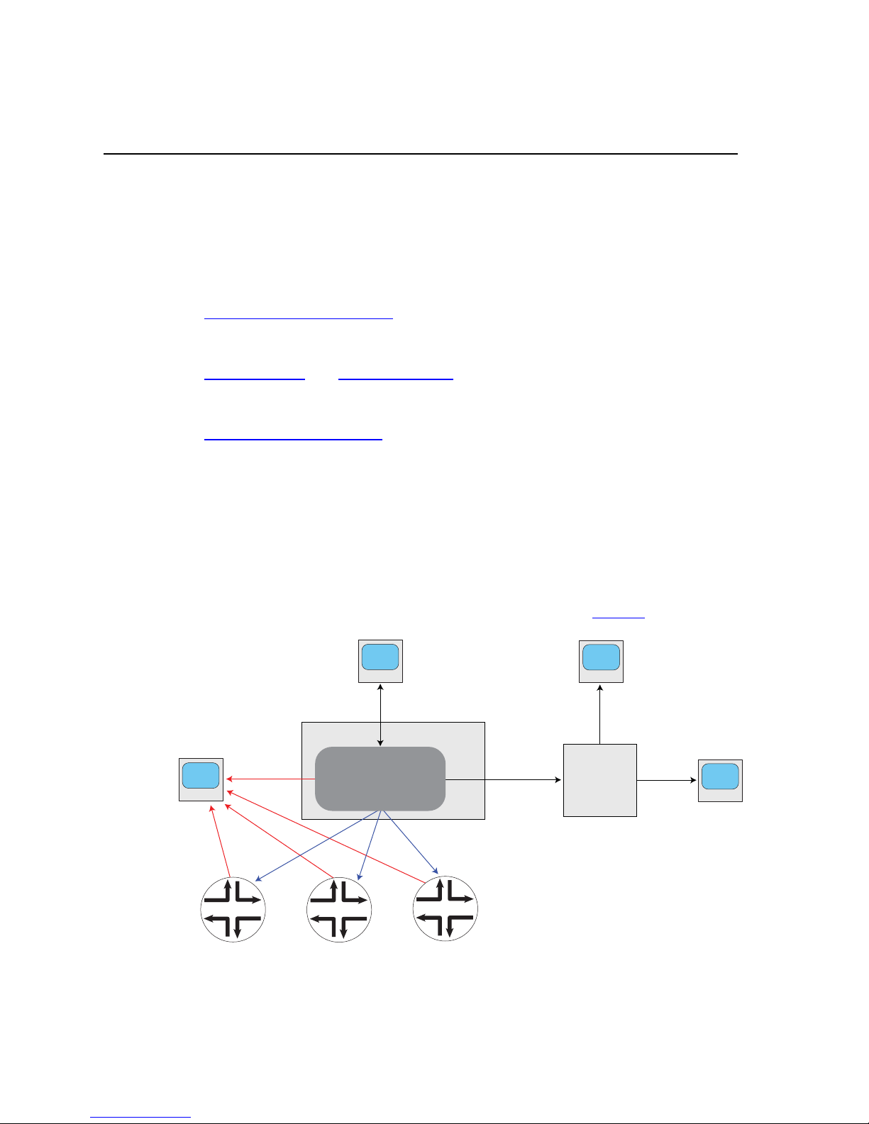
Media Flow Controller nodes can be flexibly grouped based on factors such as business
function or geographical location, for easier configuration and management. Configuration
templates can be created and applied to different groups to provision new services. Media
Flow Manager periodically performs application level polling of Media Flow Controllers to
detect service unavailability and generate alarms, if needed. See Figure 1
for illustration.
Figure 1 Media Flow Manager Interaction
For details, see the Media Flow Controller Administrator’s Guide and CLI Command
Reference.
Copyright © 2010, Juniper Networks, Inc. 25
Page 26

CHAPTER 2 Media Flow Manager Overview Media Flow Manager Administrator’s Guide
Note! Media Flow Manager is a separate product and is not a component of Media Flow
Controller. It needs to be deployed and managed separately.
Important! Media Flow Manager does not support RAID arrays.
Tip! Media Flow Manager provides a Web-based interface to manage your Media Flow
Controllers; this is described fully in Chapter 3, “Media Flow Manager Web-Based Interface."
Remote Monitoring and Management
You can use CMC to manage multiple Media Flow Controllers located anywhere in the
network. It communicates with a client running on each Media Flow Controller to collect
management information. Figure 1, “Media Flow Manager Interaction"
Controllers can be scattered in various places and managed by a single CMC.
CMC can be used to configure each of the Media Flow Controllers that the CMC manages.
You can send CLI commands to a particular Media Flow Controller, or a group of Media Flow
Controllers. You can also copy the configuration from one Media Flow Controller and apply it
to another.
Detailed management information about each Media Flow Controller that a CMC manages,
including operational state, disk space, CPU utilization, and software version is provided as
well as summary information about the CMC console.
CMC allows you to access the Management Console of each of the Media Flow Controllers it
manages. You log into, configure, manage, and control a particular Media Flow Controller.
Media Flow Manager logs show the behavior of managed Media Flow Controller’s with respect
to their operational status. The logging infrastructure provides time-based logs to correlate
Media Flow Controller behavior at different times.
shows how Media Flow
Fault Management
CMC provides a real-time fault management of the managed Media Flow Controllers. It
constantly checks the live status of the Media Flow Controller by sending periodic HTTP
“heartbeats.” CMC has the ability to view the full health of appliance(s)—including all system
resources. It uses different colors for in-service versus out-of-service Media Flow Controllers.
CMC can be configured to send SNMP traps for certain alarm generations. CMC also uses
various logs for different events.
Groups and Profiles
CMC allows multiple Media Flow Controllers to be grouped together for ease of configuration
and management. CMC also allows administrators to create profiles, i.e. configuration items
that are grouped together. Once a profile is created, it can be applied to an individual Media
Flow Controller or a configured group of Media Flow Controllers.
CMC can also use a mutual authentication between the Media Flow Controllers and itself
using configurable shared secrets.
26 Copyright © 2010, Juniper Networks, Inc.
Page 27

Media Flow Manager Administrator’s Guide CHAPTER 2 Media Flow Manager Overview
Central Management Console
This section describes how the Central Management Console (CMC) works; first, terminology:
• Media Flow Manager Server: The machine running the CMC software managing clients.
• CMC Client: The software on a Media Flow Controller being managed by a CMC server.
• CMC Rendezvous: A way to establish the connection between the CMC server and the
CMC client. In this method the Media Flow Controller is pre-configured with the CMC
server information and when the Media Flow Controller comes up it requests connectivity
to the CMC; on the CMC you authorize the Media Flow Controller and the connection gets
established. The other method for connectivity is explicitly configuring the Media Flow
Controller information on the CMC.
The CMC function of Media Flow Manager is server-client based. You configure the CMC
server with a list of Media Flow Controller appliances and it runs the Remote Box
Management Daemon (RBMD). In the standard server-initiated connection scenario, the CMC
server is configured with a means of logging into an administrator account on each client
Media Flow Controller using a password, or SSH v2 RSA or DSA keys, opening a connection,
and proxying requests between the two.
In the client-initiated connection scenario, the Media Flow Controller CMC client logs into the
CMC server using a password, or SSH v2 RSA or DSA keys, opens a connection, and the
same lines of communication are established as with the server-initiated connection.
Some of CMC’s management tasks are accomplished through requests that are proxied.
Other tasks are accomplished by sending the client lists of CLI commands that are executed
locally.
Appliances (Media Flow Controllers)
An appliance represents a single remote system that the CMC manages. It contains the
address of the system, and credentials that can be used to log into it. The credentials may
either be a password, or the name of an identity record (see “Identities,"
which authentication type is selected. Each authentication type can specify with a username to
log in as; the user specified should have administrative privileges for the CMC to manage the
appliance correctly; admin is the default user. Note that for client-initiated connections, the
server does not need these credentials in the appliance record. The central administrator sets
up one or more local accounts for the clients to log into, and gives this login information to the
remote administrators.
Groups
A group record contains references to any number of appliance records. Any action that can
be performed on an appliance, such as applying a profile (executing a set of CLI commands),
can also be performed on a group. An appliance may belong to any number of groups. There
is one reserved group, all, which is automatically maintained to contain every configured
appliance.
below), depending on
Central Management Console 27
Page 28

CHAPTER 2 Media Flow Manager Overview Media Flow Manager Administrator’s Guide
Identities
An identity is an RSA or DSA key pair that can be used to log into a managed appliance. Each
identity has a name, which is an administrator-assigned string used to refer to it. Most
commonly, the administrator can ask for an identity to be generated automatically; but an
identity can also be created by specifying the public and private key directly. When specifying
the credentials to use to log into an appliance, the administrator can provide a username and
the name of the identity to use, as an alternative to a username and password.
Profiles
A profile is a stored list of CLI commands that can be run on remote appliances or groups.
When a profile is applied, the non-local configuration on the remote system is first reset to its
defaults. "Local" configuration in this context is anything system-specific that should not be
shared between systems. By default, this is the network interface and route configurations
required for basic network connectivity.
Profiles can be created from the CLI by specifying their lists of commands directly, or from the
Web-based Media Flow Manager Central Management Console (CMC). The CMC lets you
create profiles by filling out configuration forms, much like you would do to configure an
appliance directly. For example, to create a profile that configures NTP on a remote appliance,
the CMC has a special NTP configuration page that looks much like the NTP configuration
page in the Management Console of a Media Flow Controller. You enter the NTP configuration
here, and when you press Apply, the commands to configure NTP in the manner specified are
added to the selected profile. The Central Management Console also allows you to type CLI
commands to be added to a profile, for full manual control.
Status Criteria
A status criterion is one test to be applied to a remote managed appliance to determine its
status or health. These criteria are checked periodically and the results recorded, with the goal
of helping you notice problems in the appliances being managed. You cannot create status
criteria in CMC, but you can enable or disable specific status criteria.
Rendezvous
The rendezvous feature mainly impacts appliances and identities on the server side. The
server is generally configured with one or more identities at manufacture time, which it later
uses to log into clients to manage. The server and client are configured with other information
that allow them to find and authenticate each other. The rendezvous process then ultimately
results in new appliance records being added semi-automatically to the server's configuration.
An administrator at the CMC server must confirm each client before the server starts
managing it. The CMC server may also be put into an auto-accept mode where it immediately
accepts any client that presents itself. The server may then log into each approved client, also
using preconfigured credentials.
28 Central Management Console Copyright © 2010, Juniper Networks, Inc.
Page 29

Media Flow Manager Administrator’s Guide CHAPTER 2 Media Flow Manager Overview
Media Flow Controller
San Francisco
East Coast user
Central US user
Content delivery network
g015424
Central
Management
Console
with
Service Director
Application
West Coast user
Media Flow Controller
New York
Server
www.example.com
3
4
5 65 6 5 6
1 2 1 2
3
4
Service Director
This section describes how the Service Director feature works. Online video viewing can be
significantly improved by delivering content from a location close to the user. Juniper Networks
Service Director application is a cost-effective and easy to deploy solution to direct video
requests to the nearest content server and deliver location specific content. The benefits are:
• Better customer traction with improved Quality of viewing Experience (QoE) and localized
content
• Eliminate transit bandwidth costs by delivering video from servers within the ISP’s network
Note! The Service Director application is not a replacement for Global Server Load Balancing
(GSLB) or the DNS infrastructure that provide many additional services.
Figure 2 How Service Director Works
1. User clicks on a video at example.com
2. Server returns HTML embedded with Flash player
3. Flash player makes a Web query to the Service Director to get the edge server’s
hostname
4. Service Director returns an XML response with the HOST field containing the server
address (Media Flow Controller or Content Delivery Network) based on the user’s location
5. and 6. The Video is delivered
The player and/or portal contacts the Service Director which uses the source IP from the
HTTP header or the IP address in the HTTP query URL and resolves it to one of continent/
country/state/city/ZIP/ISP. Based on the match, an XML file is returned to the Media Flow
Controller making the query with several details. From the XML file the Media Flow Controller
figures out which server to contact. The XML file can be auto-created based on configuration,
Service Director 29
Page 30

CHAPTER 2 Media Flow Manager Overview Media Flow Manager Administrator’s Guide
or pre-created according to a given format, or even with a proprietary format as long as the
client will understand the response.
Admission Control
Admission Control works with Service Director. Media Flow Manager runs the Service Director
mechanism to control the edge servers that serve client requests for content, based on the
geographical location of the client. Service Director allows you to configure the closest Media
Flow Controller for a given geographical location. Admission Control leverages the interface
statistics from the Media Flow Controllers and controls the outgoing bandwidth for the content
served by the Media Flow Controllers using the Service Director.
Media Flow Controllers are designed to track the interface stats (RX bytes and TX bytes) on
every network interface. In a typical setup, the TX bytes would be the content delivered by the
Media Flow Controller while the RX bytes would the data fetched from the origin server. The
Media Flow Manager Admission Control feature fetches the interface stats from the Media
Flow Controllers at regular intervals (5 minutes). These RX and TX stats from the various
Media Flow Controllers are then collated to calculate the delivered bandwidth and the received
bandwidth. These collated bandwidths are recorded and plotted on a graph for easy viewing in
the Media Flow Manager. The Service Director uses the configuration of location-to-host
mapping to return an XML with the host name of the edge Media Flow Controller based on the
client’s location. To assist with Admission Control, configure a high watermark bandwidth
and low watermark bandwidth used by the Service Director in the following way:
• If the current bandwidth measured in the last 5 minutes goes above the set high
bandwidth watermark, the Service Director only returns the default configured host
(typically the CDN). This would mean that no new traffic comes to the Media Flow
Controllers while they serve all the current requests.
• If the current bandwidth drops below the set low bandwidth watermark, the Service
Director goes back to normal operation returning hosts based on the set configuration.
This lets you throttle the aggregate bandwidth delivered by the Media Flow Controllers,
ensuring that the publisher does not pay bandwidth overage charges.
Real-Time Log File Analyzer
Juniper Networks Media Flow Manager also provides an interface to AWStats™ realtime
logfile analyzer to provide aggregated log information output to the Reports page. A full log
analysis enables AWStats to show you the following information:
• Number of visits, and number of unique visitors
• Visits duration and last visits
• Authenticated users, and last authenticated visits
• Days of week and rush hours (pages, hits, KB for each hour and day of week)
• Domains/countries of hosts visitors (pages, hits, KB, 269 domains/countries detected,
GeoIp detection)
• Hosts list, last visits and unresolved IP addresses list
• Most viewed, entry and exit pages
30 Admission Control Copyright © 2010, Juniper Networks, Inc.
Page 31

Media Flow Manager Administrator’s Guide CHAPTER 2 Media Flow Manager Overview
• Files type
• Web compression statistics (for mod_gzip or mod_deflate)
• OS used (pages, hits, KB for each OS, 35 OS detected)
• Browsers used (pages, hits, KB for each browser, each version Web, Wap, Media
browsers: 97 browsers, more than 450 if using browsers_phone.pm library file)
• Visits of robots (319 robots detected)
• Worms attacks (5 worm families)
• Search engines, keyphrases and keywords used to find your site (The 115 most famous
search engines are detected like yahoo, google, altavista, etc...)
• HTTP errors (Page Not Found with last referrer, ...)
• Other personalized reports based on URL, URL parameters, referer field for
miscellaneous/marketing purpose,
For more information, please see the AWStats Website
.
Real-Time Log File Analyzer 31
Page 32

CHAPTER 2 Media Flow Manager Overview Media Flow Manager Administrator’s Guide
32 Real-Time Log File Analyzer Copyright © 2010, Juniper Networks, Inc.
Page 33

CHAPTER 3 Media Flow Manager Web-Based Interface Media Flow Manager Administrator’s Guide
CHAPTER 3
Media Flow Manager Web-Based Interface
The Media Flow Manager provides a Web-based interface (see Figure 3) to three major
services and all needed system configurations. In addition to First Time Login
(first two topics), these configuration topics are covered:
• System Config—Set up system functions, including hosts, users, security, and upgrades.
• CMC Setup—Set CMC options and add nodes and/or groups of nodes to be managed.
• CMC Profiles—Create profiles (sets of commands) and apply them to nodes and groups.
• Preset Profiles—On defined take actions on managed nodes.
• Service Director—Set GeoIP-based load distributing options.
• Admission Control—Set admission control options to work with Service Director.
and Monitoring
• View Logs—View the system log.
• Reports—For configured nodes, generate reports.
This chapter describes each page of the Media Flow Manager and each option.
Figure 3 Media Flow Manager Login Page Detail
Copyright © 2010, Juniper Networks, Inc. 33
Page 34

CHAPTER 3 Media Flow Manager Web-Based Interface Media Flow Manager Administrator’s Guide
First Time Login
To log into the Web-based interface, just navigate to the configured Media Flow Manager IP
address, and use the default login credentials: admin (no password). Example:
http://192.168.1.100
To log into the system command line interface (CLI) for the first time, you’ll need the IP
address assigned the interface.
1. Open an SSH session and enter the Media Flow Manager management IP address or
hostname, or open a serial console session with the console server IP address and port,
to connect.
2. Log in with the default credentials (there is no default password).
User: admin
Monitoring
The Monitoring tab gives you quick access to statistics and information about the current
system, including bandwidth usage, namespace usage, CPU load, and more.
Monitoring > Summary
The Summary page provides the following information. See Figure 4 for graphic.
CMC Managed Media Flow Controller Nodes
For each currently managed Media Flow Controller:
• Media Flow Controller—The managed Media Flow Controller hostname. Click on the
name link to open the Management Console for that Media Flow Controller; a login is
required. Note that configuration changes for that Media Flow Controller are greyed-out
unless you specifically choose to enable configuration.
• Enabled—Whether or not monitoring of this Media Flow Controller is enabled.
• Connected—Whether or not this Media Flow Controller is currently connected.
• Connection Duration—How long this Media Flow Controller has been connected to this
CMC.
• Alive—Whether or not this Media Flow Controller is still transmitting “alive” signals to this
CMC.
• Disk Space—How much free disk space is left on this Media Flow Controller.
• CPU Usage—How much CPU is currently being used by this Media Flow Controller.
• Version—The version of this Media Flow Controller.
34 First Time Login Copyright © 2010, Juniper Networks, Inc.
Page 35

Media Flow Manager Administrator’s Guide CHAPTER 3 Media Flow Manager Web-Based Interface
Figure 4 Monitoring > Summary Page Detail
System Information
About the Media Flow Manager running the CMC:
• Date and Time, current
• Hostname, as configured
• Uptime, since boot up
• Version, software
• Model, hardware
• Host ID, the system serial string from the motherboard
• System memory, MB used, free, and total
• Number of CPUs (central processing units)
• CPU load averages, as of uptime
Monitoring > CMC Media Flow Controllers
This page provides statistics and action options for managed Media Flow Controllers, see
Figure 5
• Media Flow Controller—The managed Media Flow Controller hostname. Click the name
• Enabled—Whether or not monitoring of this Media Flow Controller is enabled.
, next, for graphic.
link to open the Management Console for that Media Flow Controller; a login is required.
Note that configuration changes for that Media Flow Controller are greyed-out unless you
specifically choose to enable configuration.
Monitoring 35
Page 36

CHAPTER 3 Media Flow Manager Web-Based Interface Media Flow Manager Administrator’s Guide
• Connected—Whether or not this Media Flow Controller is currently connected.
• Connection Duration—How long this Media Flow Controller has been connected to this
Media Flow Manager.
• Status—Whether or not this Media Flow Controller is still connected and running.
Click the Configure CMC link to jump to the CMC Setup page. Click Detail for a selected
Media Flow Controller to get more information, see Figure 6
, next, for graphic.
Figure 5 Monitoring -> CMC Media Flow Controllers Page
Details Page
This page displays when you click a Details link for a managed node in the Managed Media
Flow Controllers table at top. See Figure 6
For each managed Media Flow Controller:
Click the Prev and Next navigation buttons to scroll through the managed Media Flow
Controllers.
Click OK to go back to the main CMC Media Flow Controllers page.
Click Refresh to update the page with new information (if any).
Click Reconnect if your Connected status is red.
36 Monitoring Copyright © 2010, Juniper Networks, Inc.
, next, for graphic.
Page 37

Media Flow Manager Administrator’s Guide CHAPTER 3 Media Flow Manager Web-Based Interface
Click Interrupt to stop a profile or command set from being applied, once application has
already started.
Click Remove Key if you need to install new Host Keys.
Figure 6 Monitoring -> CMC Media Flow Controllers Media Flow Controller Detail Window
Monitoring 37
Page 38

CHAPTER 3 Media Flow Manager Web-Based Interface Media Flow Manager Administrator’s Guide
Monitoring > CPU Load
A last-hour graph of CPU Load; choose from the drop-down menu to view Aggregated
(default), Per CPU, or Per CPU Stacked graph. Includes Pause and Resume buttons to stop/
start graph charting. See Figure 7
for graphic.
Figure 7 Monitoring > CPU Load Graph
Monitoring > Memory
A last-day graph of Memory Utilization plus a pie chart of Current Memory Statistics
including statistics of Physical and Swap memory (Total, Used, and Free). Includes Pause
and Resume buttons to stop/start graph charting.
Also a pie chart of Current Memory Statistics including statistics of Physical and Swap
memory (Total, Used, and Free).
Monitoring > Network
A last-hour graph of Network Usage including detailed information on all data ports. Includes
Pause and Resume buttons to stop/start graph charting.
Below, detailed information on all data ports: RX bytes / TX bytes, RX packets / TX packets,
RX mcast packets / TX discards, RX discards / TX errors, RX errors / TX overruns, RX
overruns / TX carrier, and RX frame / TX collisions.
38 Monitoring Copyright © 2010, Juniper Networks, Inc.
Page 39

Media Flow Manager Administrator’s Guide CHAPTER 3 Media Flow Manager Web-Based Interface
Monitoring > File System
A last-day graph of Disk Usage; includes Pause and Resume buttons to stop/start graph
charting.
Also a pie chart of config Partition Statistics including Bytes Total / Inodes Total, Bytes Free
/ Inodes Free, Bytes Used / Inodes Used, Bytes Percent Free / Inodes Percent Free, and
Bytes Available.
And a pie chart of var Partition Statistics including Bytes Total / Inodes Total, Bytes Free /
Inodes Free, Bytes Used / Inodes Used, Bytes Percent Free / Inodes Percent Free, and Bytes
Available.
System Config
Configure all system settings for the Media Flow Manager. Includes these pages.
System Config > Interfaces
Manage network interfaces options. See interface for CLI details.
eth0 state
View interface Status, IP address, Netmask, Type, Speed, Duplex, MTU, and a Comment
(if configured) for each discovered interface.
eth0 configuration
Make configurations for the eth0 interface. See Figure 8 for graphic.
• Enabled—Select to enable the interface for activity, default; or de-select the checkbox to
disable the interface, respectively.
• Obtain IP Address Automatically (DHCP)—Allow DHCP to assign the IP address for
this CMC. OR
• Specify IP Address Manually—Enter the IP address and Netmask for this CMC.
• Speed and Duplex—Choose Auto (default) for the Speed and Duplex to be set
automatically based on hardware. Or you can set these options to alternate values in the
drop-down menu. Note! Juniper Networks highly recommends that Speed and Duplex
not be changed from the auto-configured defaults.
• MTU—The Maximum Transmission Unit (MTU) sets the largest number of bytes a frame
can carry. Default is 1500.
• Comment—A description for the interface.
Click Apply to immediately apply changes; Cancel to revert to existing configuration. Click
Save at the top of the page to make changes persistent.
System Config 39
Page 40

CHAPTER 3 Media Flow Manager Web-Based Interface Media Flow Manager Administrator’s Guide
Figure 8 System Config > Interfaces Page Detail (eth0 configuration)
DHCP Primary Interface
Set DHCP (dynamic host configuration protocol) primary interface and/or verify the current
primary DHCP interface on the System Config > Interfaces page. DHCP allows new network
devices to be automatically supplied with an IP address and other information, depending on
the setup of the DHCP server. CMC has no primary DHCP interface by default. Setting a
primary interface ensures that DHCP messages arrive only on that interface; to do so, choose
a Configured primary interface from the drop-down list.
Click Apply to immediately apply changes; Cancel to revert to existing configuration. Click
Save at the top of the page to make changes persistent.
Add new interface aliases
Add a new interface alias on the System Config > Interfaces page. An interface alias lets you
assign multiple IP addresses to the same interface. You must know the Alias index, IP
address, and Netmask to use. See Figure 9
changes; Cancel to revert to existing configuration. Click Save at the top of the page to make
changes persistent.
Figure 9 System Config > Interfaces Page Detail (Add new interface alias)
40 System Config Copyright © 2010, Juniper Networks, Inc.
for graphic. Click Apply to immediately apply
Page 41

Media Flow Manager Administrator’s Guide CHAPTER 3 Media Flow Manager Web-Based Interface
System Config > Routing
Set IP Routing options, including Default Gateway and Static Routes. See
Default Gateway
On the System Config > Routing page, enter an IP address and click Set Default Gateway
to apply changes; click Save at the top of the page to make them persistent across reboots.
See Figure 10
Figure 10 System Config > Routing Page Detail (Default Gateway)
Static and Dynamic Routes
View all configured static and dynamic routes. A static route is a hard coded (manually
defined) path that specifies the route to a certain subnet using a certain path. See Figure 11
.
.
• Destination—The subnet/path for this static route.
• Mask—The netmask for this route.
• Gateway—The configured gateway (path to the Internet) for this static route.
• Interface—The port configured for this static route.
• Active—Whether or not this route is being used currently.
• Static—Whether or not this route is static (hard coded).
Select a route and click Removed Selected to immediately apply changes; click Save at the
top of the page to make them persistent across reboots.
Figure 11 System Config > Routing Page Detail (Static and Dynamic Routes)
Add Static Route
Static routes set a path in the routing table for a particular destination. You must know the
Destination you want a static route to, the Netmask, Gateway IP address, and Interface to
use. Click Add Route to apply changes; click Save to make them persistent across reboots.
See Figure 12
.
System Config 41
Page 42

CHAPTER 3 Media Flow Manager Web-Based Interface Media Flow Manager Administrator’s Guide
Figure 12 System Config > Routing Page Detail (Add Static Route)
System Config > DNS
View, add, modify, or remove Static and Dynamic Name Servers and Domain Names. See
ip for CLI details.
Static and Dynamic Name Servers
View all configured static and dynamic name servers.
• IP Address—Of the configured DNS server.
• Active—Whether or not this DNS server is being used currently.
• Source—”Configured” means it was manually added; “Dynamic” means it came from a
name server.
Add or Modify Name Servers
On the System Config > DNS page, you can set up to three Dynamic Name Servers (DNS).
See Figure 13
for graphic.
• Primary DNS IP address—This DNS server is tried first.
• Secondary DNS IP address—This DNS server is tried second.
• Tertiary DNS IP address—This DNS server is tried last.
Click Apply to immediately apply changes; Cancel to revert to existing configuration.
Click Save at the top of the page to make changes persistent.
Figure 13 System Config > DNS Page Detail (Add or Modify Name Servers)
42 System Config Copyright © 2010, Juniper Networks, Inc.
Page 43

Media Flow Manager Administrator’s Guide CHAPTER 3 Media Flow Manager Web-Based Interface
Static and Dynamic Domain Names
View all configured static and dynamic domain names:
• Domain—The configured name for that domain.
• Active—Whether or not this domain name is being used currently.
• Source—”Configured” means it was manually added; “Dynamic” means it came from a
name server.
Configured Domain Names
All configured domain names. You can select a name and click Remove Selected. See
Figure 14
for graphic. Click Save at the top of the page to make changes persistent.
Figure 14 System Config > DNS Page Detail
Add New Domain Name
on the System Config > DNS page, add a new domain name by entering a name and clicking
Add Domain Name; can be removed from the list of Configured Domain Names described
above. See Figure 15
Figure 15 System Config > DNS Page Detail
for graphic. Click Save at the top to make changes persistent.
System Config > Hostname
View or change the System Hostname. Enter a Host Name for this Media Flow Manager and
click Apply to immediately apply changes; Cancel to revert to existing configuration. Click
Save at the top of the page to make changes persistent. See Figure 16
for graphic.
System Config 43
Page 44

CHAPTER 3 Media Flow Manager Web-Based Interface Media Flow Manager Administrator’s Guide
Figure 16 System Config > Hostname Page Detail
System Config > Hosts
Set static host entries; a static host is not subject to IP address changes via DNS (dynamic
name sever.
Static Host Entries
View, configured Static Hosts (hostname/IP mappings for /etc/hosts). The default loopback
host entry cannot be removed. Select an entry and click Remove Selected to delete it. See
Figure 17
Click Save at the top of the page to make changes persistent.
for graphic, next.
Figure 17 System Config > Hosts Page Detail
Add New Host
Add a new host on the System Config > Hosts page; you must know the IP address and
Hostname to enter a static host mapping. See Figure 18
Click Add Entry to immediately apply changes. Click Save at the top of the page to make
changes persistent.
Figure 18 System Config > Hosts Page Detail
System Config > ARP (Address Resolution)
Manage Address Resolution Protocol (ARP) entries.
for graphic, next.
44 System Config Copyright © 2010, Juniper Networks, Inc.
Page 45

Media Flow Manager Administrator’s Guide CHAPTER 3 Media Flow Manager Web-Based Interface
Static and Dynamic ARP Entries
View Static and Dynamic ARP Entries. See Figure 19, next.
• IP address—The configured IP address for this entry.
• MAC address—The physical address of this entry.
• Interface—The port configured for this entry.
• Active—Whether or not this entry is being used currently.
• Static—Whether or not this entry comes from DNS.
Click Remove Selected to delete an entry. Click Save to make changes persistent.
Figure 19 System Config > ARP Page Detail
Add Static Entry
Add a new static ARP entry on the System Config > ARP page; you need the IP address and
MAC address of the system you want to add to the ARP cache as a static entry. See
Figure 20.
Click Add Entry to immediately apply changes; Cancel to revert to existing configuration.
Click Save at the top of the page to make changes persistent.
Figure 20 System Config > ARP Page Detail
Clear Dynamic ARP Cache
On the System Config > ARP page, click Clear to empty the ARP cache. See Figure 21.
System Config 45
Page 46

CHAPTER 3 Media Flow Manager Web-Based Interface Media Flow Manager Administrator’s Guide
Figure 21 System Config > ARP Page Detail
System Config > Web
Configure the Media Flow Manager Web-based interface options. See web for CLI details.
Web UI Configuration
On the System Config > Web page, configure the CMC Web-based interface. See Figure 22
for graphic.
• Enable Web Configuration—This allows configurations through the Management
Console.
• Auto Logout Timeout—Control the length of user inactivity required before the
Management Console automatically logs out a user.
• Enable HTTP and set an HTTP Port, de-select to disable HTTP.
• Enable HTTPS and set an HTTPS Port, de-select to disable HTTPS.
• Web Session Renewal—Control the length of time before Web session cookies are
automatically regenerated.
• Web Session Timeout—Configure time after which a session expires.
Click Apply to complete operation; Cancel to revert to existing configuration. You can also
Generate New HTTPS Certificate by clicking that button. Click Save at the top of the page to
make changes persistent across reboots.
46 System Config Copyright © 2010, Juniper Networks, Inc.
Page 47

Media Flow Manager Administrator’s Guide CHAPTER 3 Media Flow Manager Web-Based Interface
Figure 22 System Config > Web Page Detail (Web UI Configuration)
Web Proxy Configuration
On the System Config > Web page, set parameters for the CMC Web-based interface when
proxied. See Figure 23
• Web Proxy address—Specify a proxy to be used for any HTTP or FTP downloads.
• Web Proxy port—If no port is specified, the default is 1080.
• Authentication type—Configure the type of authentication to be used with a Web proxy;
either None or Basic.
• Basic auth userna me —If your authenticating with Basic HTTP authentication, enter a
username and.
• Basic auth password for that user.
Click Apply to complete operation; Cancel to revert to existing configuration. Click Save at the
top of the page to make changes persistent across reboots.
for graphic.
System Config 47
Page 48

CHAPTER 3 Media Flow Manager Web-Based Interface Media Flow Manager Administrator’s Guide
Figure 23 System Config > Web Page Detail (Web Proxy Configuration)
System Config > Users
View, remove, enable, disable, and add new users; plus change existing user passwords. See
username for CLI details.
Active Users
View configured users:
• Username—Used for logins.
• Full Name—For the user, as configured.
• Host—What system this user is configured on.
• Idle (seconds)—Time since the last command execution of this user.
User Accounts
For each configured user account, view information or take action. See Figure 24 for graphic.
• User—Used for logins.
• Full Name—For the user, as configured.
• Capability—The privilege level assigned this user. Capabilities are described below.
• Enabled—Whether or not this user account is enabled. User accounts are enabled by
default. Disabling an account makes it inactive (logins are disallowed) but does not delete
it from the system.
48 System Config Copyright © 2010, Juniper Networks, Inc.
Page 49

Media Flow Manager Administrator’s Guide CHAPTER 3 Media Flow Manager Web-Based Interface
Figure 24 System Config > Users Page Detail (User Accounts)
Select a user account and Remove, Enable, and/or Disable it. Click Save at the top of the
page to make changes persistent across reboots.
Add New User
On the System Config > User page, add a new user to Media Flow Manager. See Figure 25.
• User—Login name.
• Full YPName—Displays in User Accounts list.
• Capability— There are three pre-defined capabilities:
• admin—Full privileges (default); in Enable mode all EXEC commands are available.
• monitor—Privileges for reading all data and performing all actions, but not for
changing any configuration.
• unpriv—Unprivileged.
Click Add User to complete operation. Click Save at the top of the page to make changes
persistent across reboots.
Figure 25 System Config > Users Page Detail (Add New User)
Change Password
For each user, admin, cmcclient, cmcrendv, and monitor are default users, set or change
the password. May be left empty if no password is required.
Click Save at the top of the page to make changes persistent across reboots.
System Config 49
Page 50

CHAPTER 3 Media Flow Manager Web-Based Interface Media Flow Manager Administrator’s Guide
System Config > SSH
View Host Keys, and Generate Host Keys. See Figure 26, next. See ssh for CLI details.
• Key Type—Either RSA1 (Rivest, Shamir, Adleman – the inventors) or DSA2 (Digital
Signature Algorithm, 2).
• Finger Print—A human-readable string so you can check the key manually.
Figure 26 System Config > SSH Page Detail
System Config > AAA (authentication)
Configure AAA (authentication, authorization and accounting) settings; accounting options are
not supported. RADIUS and/or TACACS+ authentication must be configured before these
options can be specified with this command. See aaa for CLI details.
Authentication Method List
Set the list of acceptable authentication methods for system logins. The order in which the
methods are specified is the order in which they are attempted. See Figure 27
Click Apply to complete operation; Cancel to revert to existing configuration. Click Save at the
top of the page to make changes persistent across reboots.
, next.
Figure 27 System Config > AAA Page Detail
50 System Config Copyright © 2010, Juniper Networks, Inc.
Page 51

Media Flow Manager Administrator’s Guide CHAPTER 3 Media Flow Manager Web-Based Interface
Authorization
Set authorization options. See Figure 28.
• Map Order— Determine how the remote user mapping behaves when authenticating
users via RADIUS or TACACS+. If the authenticated user name is valid locally, no
mapping is performed. Options:
• remote-first— If a local-user mapping attribute is returned and is a valid local user
name, map the authenticated user to the local user specified in the attribute.
Otherwise, if the attribute is not present or not valid locally, use the user specified as
the default-user.
• remote-only — Only try to map a remote authenticated user if the authentication
server sends a local-user mapping attribute; otherwise, no further mapping is tried.
• local-only — All remote users are mapped to the user specified by Map Default
User. Any vendor attributes received by an authentication server are ignored.
Figure 28 System Config > AAA Page Detail
System Config > RADIUS
Configure RADIUS authentication. See radius-server for CLI details.
Default RADIUS Settings
View and change Default RADIUS Settings. See Figure 29, next.
• Key—A shared secret text string. If no key is set, the user is prompted for the key.
• Timeout—Timeout for retransmitting a request to any RADIUS server. Range is 1-60,
default is 3.
• Retransmit—The number of times the client attempts to authenticate with any RADIUS
server. Range is 0-5, default is 1.
• Login-lat-group—The string that identifies the groups that the user is authorized to use
when Login-service is defined as LAT (local area transport). If none is set, the user is
prompted for the string.
Click Apply to complete operation; Cancel to revert to existing configuration. Click Save at the
top of the page to make changes persistent across reboots.
System Config 51
Page 52

CHAPTER 3 Media Flow Manager Web-Based Interface Media Flow Manager Administrator’s Guide
Figure 29 System Config > RADIUS Page Detail (Default RADIUS Settings)
RADIUS Servers
In the server list: Remove, Enable and/or Disable RADIUS Servers. see Figure 30.
• Server—The configured IP address for this RADIUS server.
• Auth-Port—The configured port for authentication requests to this server.
• Key— The configured shared secret text string. If empty, the user is prompted for the key.
• Timeout—The configured timeout for retransmitting a request.
• Retransmit—The configured number of times a client may attempt to authenticate.
• Login-lat-group—The configured string that identifies the groups that the user is
authorized to use when Login-service is defined as LAT (local area transport).
• Enabled—Whether or not this RADIUS server is enabled. Disabling a server makes it
inactive but does not delete it from the system.
Figure 30 System Config > RADIUS Page Detail (RADIUS Servers)
Add New RADIUS Server
Add a new RADIUS server, see Figure 31, below; you need this information:
• Enabled—The server must be enabled to do authentication.
• Server IP—IP address for the server.
• Auth Port—The port authentication requests should come in on; default is 1812. You can
use the same IP address in more than one host as long as the auth-port is different.
To override defaults for a new RADIUS server, you can also specify different Key, Timeout,
Retransmit, and Login-lat-group values for this RADIUS server from the default RADIUS
settings you made above. Click Add RADIUS Server to complete operation. Click Save at the
top of the page to make changes persistent across reboots.
52 System Config Copyright © 2010, Juniper Networks, Inc.
Page 53

Media Flow Manager Administrator’s Guide CHAPTER 3 Media Flow Manager Web-Based Interface
Figure 31 System Config > RADIUS Page Detail
System Config > TACACS+
Configure TACACS+ authentication. See tacacs-server for CLI details.
Default TACACS+ Settings
View and change Default TACACS+ Settings. See Figure 32, next.
• Key—A shared secret text string. If no key is set, the user is prompted for the key.
• Timeout—Timeout for retransmitting a request to any TACACS+ server. Range is 1-60,
default is 3.
• Retransmit—The number of times the client attempts to authenticate with any TACACS+
server. Range is 0-5, default is 1.
Figure 32 System Config > TACACS+ Page Detail (Default TACACS+ Settings)
System Config 53
Page 54

CHAPTER 3 Media Flow Manager Web-Based Interface Media Flow Manager Administrator’s Guide
TACACS+ Servers
In the server list: Remove, Enable and/or Disable TACACS+ Servers. See Figure 33.
• Server—The configured IP address for this TACACS+ server.
• Auth-Port—The configured port for authentication requests to this server.
• Auth-Type—The configured type of authentication this TACACS+ server will use.
• Key— The configured shared secret text string. If empty, the user is prompted for the key.
• Timeout—The configured timeout for retransmitting a request.
• Retransmit—The configured number of times a client may attempt to authenticate.
• Enabled—Whether or not this TACACS+ server is enabled. Disabling a server makes it
inactive but does not delete it from the system.
Figure 33 System Config > TACACS+ Page Detail (TACACS+ Servers)
Add New TACACS+ Server
Add a new TACACS+ server, see Figure 34, next; you need this information:
• Enabled—The server must be enabled to do authentication.
• Server IP—IP address for the server.
• Auth Port—The port authentication requests should come in on; default is 49. You can
use the same IP address in more than one host as long as the auth-port is different.
• Auth Type—Which type of authentication this TACACS+ server will use; both
authentication types transmit the username and password in un-encrypted text and are
acceptable when passwords are stored in an external database. Choose either:
• ascii—American Standard Code for Information Interchange.
• pap—Password authentication protocol (default).
To override defaults for a new TACACS+ server, you can also specify different Key, Timeout,
and Retransmit values for this TACACS+ server from the default TACACS+ settings you
made above.
Click Add TACACS+ Server to complete operation. Click Save at the top of the page to make
changes persistent across reboots.
54 System Config Copyright © 2010, Juniper Networks, Inc.
Page 55

Media Flow Manager Administrator’s Guide CHAPTER 3 Media Flow Manager Web-Based Interface
Figure 34 System Config > TACACS+ Page Detail
System Config > SNMP
Configure SNMP server options. See snmp-server for CLI details.
SNMP Configuration
Enable SNMP and set SNMP authentication parameters. See Figure 35, below, for graphic.
• Enable SNMP—Enable the SNMP server. Un-check to disable; this stops serving SNMP
variables and the sending of SNMP traps.
• Enable Communities—Enable or disable (by un-checking) community-based
authentication on this system. If disabled, the community configured is ignored.
• Enable Traps—Enable or disable (by un-checking) sending SNMP traps from this system.
The SNMP server must be enabled first. See snmp traps for details.
• Sys Contact—Set the syscontact variable served from the System MIB in MIB-II.
• Sys Location—Set the syslocation variable served from the System MIB in MIB-II.
• Read-Only Community—Set a name for read-only (ro) SNMP requests. The read-only
community means only queries are performed. In Release 2.0.2 only SNMP ro is
supported.
• Default Trap Community—The string used if no specific string has been set for the trap.
Click Apply to complete SNMP configuration, Cancel to revert to existing configuration. Click
Save at the top of the page to make changes persistent across reboots.
System Config 55
Page 56

CHAPTER 3 Media Flow Manager Web-Based Interface Media Flow Manager Administrator’s Guide
Figure 35 System Config > SNMP Page Detail (SNMP Configuration)
Trap Sinks
View, Remove, Enable, and/or Disable trap sinks; trap sinks are created enabled. An SNMP
“trap” is an unsolicited message issued by a managed device to the management station; a
“trap sink” is where the trap is sent. See snmp traps events for more information.
Add New Trap Sink
Add hosts to receive traps. See Figure 36.
• Trap Sink IP—Add hosts to receive SNMP traps.
• Community—Specify which community of traps to send to this host; default is "public."
• Trap Type—Specify the SNMP version of traps to send to this host; choices are v1 or v2c.
Click Add New Trap Sink to complete adding the new trap sink. Click Save at the top of the
page to make changes persistent across reboots.
Figure 36 System Config > SNMP Page Detail (Trap Sinks)
56 System Config Copyright © 2010, Juniper Networks, Inc.
Page 57

Media Flow Manager Administrator’s Guide CHAPTER 3 Media Flow Manager Web-Based Interface
System Config > Faults
Configure Fault Reporting options. See email for CLI details.
Fault Reporting
Set SMTP server, Domain name overrides, Return address, and other options. See Figure 37,
next.
• SMTP server—Use a hostname or IP address to set the mail relay to use to send
notification emails. Use no email mailhub to clear the entry.
• Domain name override—Use a hostname or IP address to set the domain name from
which emails are to appear to come (provided that the return address is not already fullyqualified). This is used in conjunction with the system hostname to form the full name of
the host from which the email appears to come. The rules are as follows:
a. If an email domain is specified using this command, it is always used. If the hostname
has any dots in it, everything to the right of the first dot is stripped and the email
domain is appended.
b. Otherwise, if the hostname has dots in it, it is used as is.
Otherwise, the currently-active system domain name is used. This can come either from
the resolver configuration, or from state dynamically instantiated by DHCP.
• Return address—Set the username or fully-qualified return address from which email
notifications are sent. If the string provided contains an at (@) sign, it is considered fullyqualified and is used as-is. Otherwise, it is considered just the username, and MFD
appends @<hostname>.<domain>. The default is do-not-reply, but this can be changed
to admin or as desired in case something along the line doesn't like fictitious addresses.
• Include hostname in return addr—Include (or do not include by un-checking) the
hostname in the return address for email notifications. This only takes effect if the return
address does not contain an at (@) sign.
• Enable autosupport notifications—Enable or disable (by un-checking) the sending of
email to vendor autosupport when certain failures occur.
Click Apply to complete Fault notification configuration, Cancel to revert to existing
configuration. Click Save at the top of the page to make changes persistent across reboots.
Figure 37 System Config > Faults Page Detail (Fault Reporting)
System Config 57
Page 58

CHAPTER 3 Media Flow Manager Web-Based Interface Media Flow Manager Administrator’s Guide
Notify Recipients
View and Remove Recipients for stats alarms. See email class for additional information.
See Figure 38
, next.
• Email—Address of configured recipient.
• Detail—Whether or not this recipient is sent detailed or summarized emails. Each email
potentially has both a detailed and summarized form, where the detailed form has a
superset of the information.
• Infos—Whether or not this recipient receives Info class emails.
• Failures—Whether or not this recipient receives Failure class emails.
Figure 38 System Config > Faults Page Detail (Notify Recipients)
Add New Notify Recipients
Add notify recipients; you need the following information. See Figure 39, next.
• Email Address—Address of recipient.
• Get Detail—Choose to send this recipient detailed or summarized emails.
• Infos—Choose to send this recipient Info class emails.
• Failures—Choose to send this recipient Failure class emails.
Click Add Recipient to complete adding the new notify recipient. Click Save at the top of the
page to make changes persistent across reboots.
Figure 39 System Config > Faults Page Detail (Add New Notify Recipients)
58 System Config Copyright © 2010, Juniper Networks, Inc.
Page 59

Media Flow Manager Administrator’s Guide CHAPTER 3 Media Flow Manager Web-Based Interface
System Config > Logging
Configure logging options.
Local Log Filtering
Set severity level, see Figure 40 for graphic; options are:
• Notice—
Normal but significant condition or response that could affect operations (default).
• Emerg—System is unusable or cannot recover.
• Alert—Action must be taken immediately for functioning to continue.
• Critical—An unexpected error-causing condition or response for unknown reasons.
• Error—Error conditions.
• Warning—An anomalous condition that can be ignored and functioning continue, but may
affect operations.
• Info—Normal but significant condition or response that does not affect operations.
• Debug—Messages generated by the system debugging utility.
If None is specified for the log level, Media Flow Manager does not log anything from this
class.
Click Apply to complete Log filtering configuration, Cancel to revert to existing configuration.
Click Save at the top of the page to make changes persistent across reboots.
Figure 40 System Config > Logging Page Detail (Local Log Filtering)
Local Log Rotation
Set log rotation parameters, see Figure 41 for graphic; either:
• Rotate every—Day (at midnight), Week (first day, at midnight), or Month (first day, at
midnight).
• Rotate when log reaches—Either a certain size OR a percentage of storage space. If a
size criteria is chosen, the file size is checked hourly, so if it passes the threshold in the
middle of the hour it is not rotated right away.
• Keep at most <n> log files—How many logs to maintain on the system. If the number of
log files exceeds this number (at rotation time, or when this setting is lowered), the system
deletes as many as necessary, starting with the oldest, to bring it down to this number.
Click Apply to complete Log rotation configuration, Cancel to revert to existing configuration.
Click Save at the top of the page to make changes persistent across reboots.
System Config 59
Page 60

CHAPTER 3 Media Flow Manager Web-Based Interface Media Flow Manager Administrator’s Guide
Figure 41 System Config > Logging Page Detail (Local Log Rotation)
Remote Log Sinks
View and Remove configured Log Sinks (remote servers receiving log messages from this
system). Click Save at the top of the page to make changes persistent across reboots.
• Remote Sink—Address of configured Remote Sink.
• Minimum Severity—The configured log severity level for this Remote Sink.
Figure 42 System Config > Logging Page Detail (Remote Log Sinks)
Add New Remote Sinks
Enter IP address and and choose a Minimum Severity level (described above). See
Figure 43
Click Apply to complete Remote Sink configuration, Cancel to revert to existing configuration.
Click Save at the top of the page to make changes persistent across reboots.
for graphic.
Figure 43 System Config > Logging Page Detail (Add New Remote Sink)
60 System Config Copyright © 2010, Juniper Networks, Inc.
Page 61

Media Flow Manager Administrator’s Guide CHAPTER 3 Media Flow Manager Web-Based Interface
Log Format
Choose either Standard (default) or WELF (Web trends Enhanced Log Format). If you
choose WELF, a WELF firewall name option displays; specify the firewall name that should
be associated with each message logged in WELF format. If no firewall name is set, the
hostname is used by default. See Figure 44
Figure 44 System Config > Logging Page Detail (Log Format)
for graphic.
System Config > Configurations
Manage configuration files. See configuration and image for CLI details.
Configuration Files
Select a file and use the buttons to Delete it, Switch To that configuration, or Download the
selected configuration as a binary file. See Figure 45
, below. For each Configuration File:
• Filename—Name of the configuration.
• Active—Whether or not the configuration is currently in use.
Select a configuration and Delete, Switch, and/or Download it. Click Save at the top of the
page to make changes persistent across reboots.
Figure 45 System Config > Configurations Page Detail (Configuration Files List)
Active Configuration
For the current, active configuration: Save it to the active configuration file, Revert the running
configuration to the saved active configuration, Reset both the running and the active
configuration files to the factory defaults, or Save As a new file. See Figure 46
, below.
System Config 61
Page 62

CHAPTER 3 Media Flow Manager Web-Based Interface Media Flow Manager Administrator’s Guide
Figure 46 System Config > Configurations Page Detail (Active Configuration)
Upload Configuration File
Upload as local binary file or a local text file. See Figure 47, below. Choose either:
• Upload local binary file—Save the current configuration as a file.
• Upload local text file—Execute a set of CLI commands in a text file you upload.
Figure 47 System Config > Configurations Page Detail (Upload Configuration)
Execute CLI Commands
Use this text box to enter CLI commands to be executed ad-hoc.
Import Configuration
Retrieve a configuration from a remote system. See Figure 48 for graphic.
• Hostname or IP address—The location of the desired configuration.
• Remote Username—Login username.
• Remote Password—Login password for the set Remote Username.
• Remote Config Name—File name of the desired configuration.
• New Config Name—A new name for the imported configuration (optional).
62 System Config Copyright © 2010, Juniper Networks, Inc.
Page 63

Media Flow Manager Administrator’s Guide CHAPTER 3 Media Flow Manager Web-Based Interface
• Import shared data only—Uncheck to import all nodes, even those not available on this
system.
Figure 48 System Config > Configurations Page Import Configuration Detail
System Config > Date and Time
Set system Date and Time, and Time Zone; enable/disable NTP time synchronization. See
Figure 49
existing configuration. Click Save at the top of the page to make changes persistent.
Figure 49 System Config > Date and Time Page Detail
for graphic. Click Apply to complete Date and Time setup, Cancel to revert to
System Config 63
Page 64

CHAPTER 3 Media Flow Manager Web-Based Interface Media Flow Manager Administrator’s Guide
System Config > NTP
Configure Network Time Protocol (NTP) options. See ntp for CLI details.
NTP Setup
Enable/disable NTP time synchronization. Click Apply to finish, Cancel to revert to existing
configuration. See Figure 50
across reboots.
Figure 50 System Config > NTP Page Detail (NTP Setup)
NTP servers
View configured NTP servers; see Figure 51, next. For each:
• Server—IP address of the NTP server.
• Status—Whether or not the server is currently in use.
• Stratum—The hierarchical system this NTP server uses.
• Offset (ms)—Whether or not an offset (a degree in milliseconds of difference) of the
server’s time is configured.
• Reference Clock—How the NTP server is finding its reference (base) clock; INIT means
this is configured in the /etc/init.d directory.
. Click Save at the top of the page to make changes persistent
• Poll Interval (sec.)—How often the server exchanges information with its configured
reference clocks.
• Last response (sec.)—When the last response from the reference clock was received.
• NTP version—The set version of NTP.
Select a server and Remove, Enable, and/or Disable it. Click Save at the top of the page to
make changes persistent across reboots. NTP servers are enabled by default.
Figure 51 System Config > NTP Page Detail (NTP Servers)
64 System Config Copyright © 2010, Juniper Networks, Inc.
Page 65

Media Flow Manager Administrator’s Guide CHAPTER 3 Media Flow Manager Web-Based Interface
Add New NTP Server
Enter NTP server IP address, version, and enable/disable. See Figure 52, next.
Figure 52 System Config > NTP Page Detail (Add New NTP Server)
System Config > Licensing
Use this page to view and remove installed licenses, and add new licenses.
Installed Licenses
View and Remove licenses. See Figure 53 for graphic.
Figure 53 System Config > License Page Detail (Installed Licenses)
Add New License(s)
Use this area to manually enter a license key. See Figure 54 for graphic.
System Config 65
Page 66

CHAPTER 3 Media Flow Manager Web-Based Interface Media Flow Manager Administrator’s Guide
Figure 54 System Config > License Page Detail (Add New License(s))
Click Add License to complete adding the new license.
Click Save at the top of the page to make changes persistent across reboots.
System Config > Reboot
Reboot or Shutdown the appliance. See Figure 55 for graphic.
A reboot brings up the same configuration that was last active.
Figure 55 System Config > Reboot Page Detail
System Config > Upgrade
Use this page to install upgrades. See image for CLI details.
Installed Images
View installed images and Switch Boot Partition. You may need to switch the boot partition if
the image you want to install is in the other partition. See Figure 56
Click Save at the top of the page to make changes persistent across reboots.
for graphic.
66 System Config Copyright © 2010, Juniper Networks, Inc.
Page 67

Media Flow Manager Administrator’s Guide CHAPTER 3 Media Flow Manager Web-Based Interface
Figure 56 System Config > Upgrade Page Detail (Installed Images)
Install New Image
To set partition; use Switch Boot Partition, above, if needed. See Figure 57 for graphic.
• Install from URL—Enter the URL and file path of the install image.
• Install via SCP—Enter the URL and file path of the install image and a password allowing
access.
• Install from local file—Use the Browse button to locate the file on your local system.
• View image upgrade process— When this is checked, you get a progress bar and status
messages of the upgrade process.
Click Install Image to complete upgrade. Click Save at the top of the page to make changes
persistent across reboots.
Figure 57 System Config > Upgrade Page Detail (Install New Image to Partition N)
System Config 67
Page 68

CHAPTER 3 Media Flow Manager Web-Based Interface Media Flow Manager Administrator’s Guide
CMC Setup
Configure the Central Management Console. As administrator of a Media Flow Manager, in
addition to all normal system setup (interfaces, email notifications, etc.; see Syst em Config)
you have the following decisions to make and tasks to perform, at a minimum.
Table 2 CMC Setup Considerations and Tasks
Consideration Task
Which Media Flow Controllers do you want to
manage with this Media Flow Manager?
What groups of Media Flow Controllers do you
want to create (if any)?
In addition to manually adding Media Flow
Controllers, you can set up a rendezvous
mechanism that causes properly configured Media
Flow Controllers to initiate connection to server
themselves. Do you want to use rendezvous ?
What profiles (sets of commands) do you want to
create and how? You can create profiles via a
configured Media Flow Controller or by manually
entering commands.
What nodes or groups do you want to apply your
profiles to?
CMC Setup > Media Flow Controllers
Use this page to add Media Flow Controllers to CMC for management. Once you add an
appliance in this way, the configuration options for that appliance become greyed-out unless
you log in to the appliance through the CMC. For Media Flow Controller details, see
“Configuring CMC (Central Management Console) Options” on page 70
Controller Administrator’s Guide and CLI Command Reference.
CMC Setup > Media Flow Controllers
CMC Setup > Groups
CMC Setup > Rendezvous
Create Profiles
CMC Profiles > Apply Profile
of the Media Flow
CMC - Media Flow Controller
This list of currently managed Media Flow Controllers includes the following information for
each. See Figure 58
• Name—The name you configured as the Media Flow Controlle r ID when you added it.
• Address—The IP address of the Media Flow Controller.
• Groups—Any defined Group that the Media Flow Controller belongs to (can belong to
more than one).
• Enabled—Whether or not monitoring of this Media Flow Controller is enabled.
• Status—The latest status report of this Media Flow Controller.
• Comment—The comment you entered for the Media Flow Controller when you added it.
Use Remove to delete the selected Media Flow Controllers from CMC management; Disable
to temporarily stop CMC from managing the selected Media Flow Controllers; Enable to allow
68 CMC Setup Copyright © 2010, Juniper Networks, Inc.
, next, for graphic.
Page 69

Media Flow Manager Administrator’s Guide CHAPTER 3 Media Flow Manager Web-Based Interface
management to the selected Media Flow Controllers; and Refresh to update the page with the
latest information.
Figure 58 CMC Setup Page Detail (Managed Nodes List)
Add New Media Flow Controller Node
For each Media Flow Controller that you want this CMC to manage you’ll need a name, IP
address, and authentication type with applicable values. See Figure 59
do this using the CLI, see cmc appliance.
1. In the Add New Media Flow Controller Node area, enter the following information for
each Media Flow Controller you want to manage:
• Media Flow Controller ID—A meaningful name.
• Media Flow Controller Address—The Media Flow Controller’s IP address.
• Comment—A brief description of this Media Flow Controller.
• Enabled—Enables monitoring of this Media Flow Controller.
• Authentication Type—How this CMC will authenticate the client Media Flow
Controller and how the client Media Flow Controller will authenticate this CMC. You
need only set one authentication type. Choices are:
• password—(default) If selected, enter a password below in the Password for
password auth option. You’ll use this to log in as the set Username for
password auth user.
• ssh-dsa2—If selected, enter an Identity below in the Identity for ssh-dsa2 auth
option. You’ll use this to log in as the set Username for ssh-dsa2 auth user.
• ssh-rsa2—If selected, enter an Identity below in the Identity for ssh-rsa2 auth
option. You’ll use this to log in as the set Username for ssh-rsa2 auth user.
• Username for password auth—A username for password authenticated logins;
default is admin.
• Password for password auth—The password for password authenticated logins;
default is none (empty).
• Username for ssh-dsa2 auth—A username for ssh-dsa2 authenticated logins;
default is admin.
, next, for graphic. To
CMC Setup 69
Page 70

CHAPTER 3 Media Flow Manager Web-Based Interface Media Flow Manager Administrator’s Guide
• Identity for ssh-dsa2 auth—The configured identity for ssh-dsa2 authenticated
logins; you set this on the CMC Setup > Identities page (see CMC Setup > Identities
below); any identities you’ve set you can choose from the drop-down list.
• Username for ssh-rsa2 auth—A username for ssh-rsa2 logins; default is admin.
• Identity for ssh-rsa2 auth—The configured identity for ssh-rsa2 authenticated
logins; you set this on the CMC Setup > Identities page (see CMC Setup > Identities
below); any identities you’ve set you can choose from the drop-down list.
• Admin First Name, Last Name, E-mail, Phone Number, and Alternate Phone—
Enter the contact information of the administrator you are adding.
2. Click Add Media Flow Controller to complete the adding the new node. The new node
displays in the CMC-Media Flow Controller table at the top of the page. Also, a checkbox
for the new node displays on the Groups page for each configured group.
• Click the node Name link in the table to open a new window to that appliance; login
required. All configuration options are dis-allowed (greyed-out) by default, you change
this by clicking the Config changes disabled change link at the top right of any page.
• Click the Status link to open a Status Details page.
• Click the Edit link to open an Edit page for the selected node.
3. Click Save at the top of the page to make changes persistent across reboots.
,
,
Figure 59 CMC Setup Page (Add New Node)
70 CMC Setup Copyright © 2010, Juniper Networks, Inc.
Page 71

Media Flow Manager Administrator’s Guide CHAPTER 3 Media Flow Manager Web-Based Interface
CMC Setup > Groups
Once you’ve added the Media Flow Controllers that you want to manage, you can group them
logically. A group can be treated acted on as an individual appliance.
See Figure 60
1. Enter a Group Name and Comment (optional) and click Add Group. A new page area
displays for the just-added group with checkboxes for each managed node.
2. Select each node that you want to include in the group and click Apply. To remove a node,
simply un-check its checkbox and click Apply again.
3. Click Save at the top of the page to make changes persistent across reboots.
Group all, Group <n>
Group all is a special group containing all available Media Flow Controllers. Beneath it are
configured groups.
Click Apply to complete the adding a Comment, Cancel to revert to existing configuration,
and Remove group (not available for default all group) to delete a group. Click Save at the
top of the page to make changes persistent across reboots.
, next, for graphic. For CLI details, see cmc auth. To add a CMC group:
Figure 60 CMC Setup > Groups Page Detail
CMC Setup > Identities
Use this page to create Media Flow Manager identities for authentication with ssh-dsa2 or sshrsa2. See Figure 61
for graphic. See cmc auth for CLI details on the options.
CMC Setup 71
Page 72

CHAPTER 3 Media Flow Manager Web-Based Interface Media Flow Manager Administrator’s Guide
Media Flow Manager is able to authenticate client connection requests using ssh-dsa2 or sshrsa2. This is optional, you can simply use the default password authentication method; default
user is admin, password is none (empty). For CLI details, see cmc auth. If you want to use
ssh-dsa2 or ssh-rsa2 identities:
1. Enter an Identity Name for either ssh-dsa2 or ssh-rsa2 and click Genera te Identity. The
generated identity displays in the list table at the top of the page and is available to be
selected in the drop-down list to Push to an appliance. It also becomes available in the
drop-down list for that identity type on the CMC Setup > Media Flow Controllers page.
2. For any managed node that you want to use this identity for connections, select the
Identity in the drop-down list and the Appliance, enter a Username and Password, and
click Push Identity. Now, when you go to log in to that node, you will use the Username
and Password you entered and will be authenticated with the identity keys you generated.
3. Click Save at the top of the page to make changes persistent across reboots.
Figure 61 CMC Setup > Identities Page
72 CMC Setup Copyright © 2010, Juniper Networks, Inc.
Page 73

Media Flow Manager Administrator’s Guide CHAPTER 3 Media Flow Manager Web-Based Interface
CMC Setup > Rendezvous
Rendezvous is the mechanism by which Media Flow Controllers connect to a CMC for
management. This page lets you set parameters for Media Flow Controllers to connect
automatically. See Figure 62
The CMC Setup > Rendezvous page lets you tell CMC to accept clients who request
management. In order for this option to work, you must enable CMC rendezvous on the client
(managed node or node-to-be-managed) first. This can be included in a Profile you create.
For Media Flow Controller details, see “Configuring CMC (Central Management Console)
Options” on page 70 of the Media Flow Controller Administrator’s Guide and CLI Command
Reference.
1. Once your nodes have been configured to rendezvous with your CMC server, enable
automatic rendezvous by selecting the Accept new clients automatically checkbox and
clicking Apply. All appliances that have been configured to rendezvous with this CMC
server display in the Rendezvous Requests Pending table.
2. Use the buttons to act on the pending rendezvous requests:
• Refresh Listing—Update the display with latest information.
• Accept Selected—The selected pending rendezvous are accepted and cleared from
the pending list.
, next, for graphic.
• Accept All—All pending rendezvous are accepted and the list is cleared.
• Reject Selected—Pending rendezvous are rejected and cleared from the list.
• Reject All—All pending rendezvous are rejected and the list is cleared.
3. Click Save at the top of the page to make changes persistent across reboots.
Figure 62 CMC Setup > Rendezvous Page Detail
CMC Setup 73
Page 74

CHAPTER 3 Media Flow Manager Web-Based Interface Media Flow Manager Administrator’s Guide
CMC Profiles
Use these pages to create and manage profiles (sets of commands), and apply them to
individual or groups of managed Media Flow Controllers.
Use the CMC Profiles pages to create and manage profiles (sets of commands). Once you
create a profile, configure the system options, DNS and Hosts, Web, Users, AAA, RADIUS,
TACACS+, SNMP, Faults, Logging, NTP, Licensing, and Upgrade settings for that profile.
Note! To set service options (Delivery Network, Delivery Protocol, Virtual Player,
Namespace, Media-Cache, and Access/Error Log), you must either enter CLI commands
directly to the profile, or create a profile from an Media Flow Controller configured with all of
the service options you want.
Manage Profiles
The CMC Profiles > Manage Profiles page, see Figure 63 for graphic, opens with a list of all
configured profiles and this information for each:
• Name—The name you gave the profile when you created it.
• Comment—The comment you added to the profile when you created it.
To delete an existing profile, select it and click Remove Selected. Click Save at the top of the
page to make changes persistent across reboots.
Figure 63 CMC Profiles Page (Manage Profiles)
Create Profiles
The CMC Profiles > Manage Profiles page is where you create profiles, sets of commands,
that you can then apply to individual managed nodes or groups of managed nodes. See
Figure 64
1. Enter a Name for the profile, a Comment (optional), and choose either a Source
2. To view the profile, all its commands and their sequence, and make changes, click a
3. You can Edit the comment for the selected profile; click Apply when done. The comment
74 CMC Profiles Copyright © 2010, Juniper Networks, Inc.
, next, for graphic. To create a profile, follow these steps.
Appliance from the drop-down list or a configured Source Profile, or leave the selections
as (none) and click Add Profile. The new profile displays in the CMC Profiles table at the
top of the page.
Name link for an existing profile. The Edit Profile page displays with information and
action options on the selected profile. You can select a configured Profile name from the
drop-down list and click Select (if needed) to edit a profile.
for that profile changes.
Page 75

Media Flow Manager Administrator’s Guide CHAPTER 3 Media Flow Manager Web-Based Interface
4. You can add a Generic Command by entering a Sequence # for where in the sequence
of existing commands for that profile this command should be executed, and entering a
CLI command in the Command text box. Click Add Command and that command
displays, in order, in the All commands list for that profile.
5. In the All commands for CMC profile “<profile>” area, each command issued to
configure the selected profile displays, in sequenced order, with a checkbox next to it. You
can select any displayed command for the selected profile and click Remove. The
command goes away from the profile.
6. Click Save at the top of the page to make changes persistent across reboots.
Figure 64 CMC Profiles Page
CMC Profiles > Apply Profile
You use the CMC Profiles > Apply Profile page to apply configured profiles to managed
nodes or groups. Note! When you apply a profile, its CLI commands are added to the existing
configuration on the appliance. See Figure 65
1. Select one of the radio buttons:
• Profile—Choose a configured profile from the drop-down list.
• CLI commands—Enter commands, in desired execution order, one per line.
• Single CLI command—Enter a single CLI command with the secure echo (only
asterisks display).
2. Select either an Appliance or Group from the drop-down lists.
3. Select options:
• Reset appliance configuration beforehand—Use this option to wipe most
configurations on the client system before applying the profile. These configurations
that may be better un-changed with a profile application are maintained: hostname,
interfaces, routes, ARP, SSH, timezone, and licenses. This is disabled by default.
• Save appliance configuration to persistent storage afterwards—Does a save
operation on the managed node(s) after the profile is applied.
4. Click Save at the top of the page to make changes persistent across reboots.
, next.
CMC Profiles 75
Page 76

CHAPTER 3 Media Flow Manager Web-Based Interface Media Flow Manager Administrator’s Guide
Figure 65 CMC Profiles > Apply Profile Page
CMC Profiles > Edit Profile
Use this page to edit a configured profile chosen from the Profile name drop-down list. See
Figure 66
76 CMC Profiles Copyright © 2010, Juniper Networks, Inc.
, next, for graphic. See cmc profile for CLI details.
Page 77

Media Flow Manager Administrator’s Guide CHAPTER 3 Media Flow Manager Web-Based Interface
Important! When you edit a profile, you must re-apply it to the nodes and/or groups that you
want to have that profile; the changes are not automatically pushed out.
Figure 66 CMC Profiles > Edit Profile Page Detail (Select Profile)
Edit comment for CMC profile <profile>
Enter a new comment or change the existing comment. See Figure 67, next, for graphic. Click
Apply to complete the change, Cancel to return to the previous configuration, and Save at the
top to make changes persistent.
Figure 67 CMC Profiles > Edit Profile Page Detail (Edit Comment)
Add Generic Command
Enter a Sequence #, you can look at the commands already configured for that profile below
in the All commands for CMC profile <profile> list to determine a sequence, and a CLI
Command string. See Figure 68
Click Add Command to complete the add operation. Click Save at the top to make changes
persistent across reboots.
Figure 68 CMC Profiles > Edit Profile Page Detail (Add Generic Command)
, next, for graphic.
All commands for CMC profile <profile>
View all of the commands comprising the selected profile. Select commands you would like to
remove from the profile and click Remove. See Figure 69
Click Save at the top to make changes persistent across reboots.
, next, for graphic.
CMC Profiles 77
Page 78

CHAPTER 3 Media Flow Manager Web-Based Interface Media Flow Manager Administrator’s Guide
Figure 69 CMC Profiles > Edit Profile Page Detail (All Commands)
System Configuration For a Selected Profile
Once you select a profile on the Edit Profile page, all of the navigation links at the left operate
only on the selected profile so you can make system configuration changes to the profile.
Once changes are made, you must re-apply it to any nodes or groups that have had that
profile applied. The links at left for editing profiles are given below.
DNS and Hosts
See “System Config > DNS” on page 42
and “System Config > Hosts” on page 44.
Web
See “System Config > Web” on page 46
.
Users
See “System Config > Users” on page 48
.
AAA (authentication)
See “System Config > AAA (authentication)” on page 50
RADIUS
See “System Config > RADIUS” on page 51
.
TACACS+
See “System Config > TACACS+” on page 53
.
SNMP
See “System Config > SNMP” on page 55
.
Faults
See “System Config > Faults” on page 57
.
Logging
See “System Config > Logging” on page 59
.
NTP
See “System Config > NTP” on page 64
.
Licensing
See “System Config > Licensing” on page 65
.
.
78 CMC Profiles Copyright © 2010, Juniper Networks, Inc.
Page 79

Media Flow Manager Administrator’s Guide CHAPTER 3 Media Flow Manager Web-Based Interface
Upgrade
See “System Config > Upgrade” on page 66
.
Preset Profiles
The Preset Profiles pages let you take certain actions on configured profiles and Media Flow
Controllers.
Preset Profiles > Preset Actions
For the selected Media Flow Controller or group, you can use Preset Actions.
Show Namespace
On the Preset Profiles > Show Namespace page, select an individual Media Flow
Controller Node or Group and click Show Namespace. A new window opens with all of the
namespace settings configured on that node or the profile assigned to that node or Group.
See Figure 70
next.
Figure 70 Preset Profiles > Show Namespace Page Detail
Purge Objects
Purge all the objects or enter a criteria to purge selected objects. See Figure 71 for graphic.
Select a managed Media Flow Controller or Group from the drop-down lists and Enter a
namespace name for same. You can use the Show Namespace page to find the
namespaces of a given Media Flow Controller or group. See cmc auth in the Media Flow
Controller Administrator’s Guide and CLI Command Reference for details. All objects stored
Preset Profiles 79
Page 80

CHAPTER 3 Media Flow Manager Web-Based Interface Media Flow Manager Administrator’s Guide
by MFD, RAM cache and disk cache, are stored as UUID:/uri/filename, this option derives
UUID from the specified namespace.
Once the namespace is selected, choose from these options to purge objects:
• All—Delete all objects in that namespace’s disk cache.
• Pattern—Delete objects based on patterns. For Release 2.0.2, only the asterisk (*)
wildcard is available for pattern use. Asterisk (*) matches zero or more characters of any
kind
• URI—All objects stored by Media Flow Controller, RAM and disk cache, are stored as
UUID:/uri/filename; this options deletes all objects of the given namespace with that URI.
Click Purge Objects to complete the object purge and Save at the top of the page to make
changes persistent across reboots.
Figure 71 Preset Profiles > Purge Objects Page Detail
Audit Nodes
Use this page to check a Media Flow Controller configuration against the profile configuration
applied to it. Do this if you suspect that node’s or node group’s configuration has changed
after a profile was applied. See Figure 72
Important! You must create a baseline audit for your nodes and/or groups by clicking Audit
Node pro-actively; do this anytime a new profile is applied or changes are made.
80 Preset Profiles Copyright © 2010, Juniper Networks, Inc.
for graphic.
Page 81

Media Flow Manager Administrator’s Guide CHAPTER 3 Media Flow Manager Web-Based Interface
Figure 72 Preset Profiles > Audit Nodes Page Detail
Preset Profiles > Preset Config
For the selected Media Flow Controller or group, you can verify a Preset Config.
Apply Probe
Setup a probe namespace that can be used by probes, such as load-balancer probes, to
check the health of nodes. When a node or group is selected and the Apply Probe button is
pressed, Media Flow Manager creates a namespace on the node(s) with (name)
generic_probe, (uri-prefix) /probe, (domain) any, and the Media Flow Manager as the originserver. This namespace cannot be deleted.
There is a pre-loaded object (probe.dat) in the Media Flow Manager that can be requested of
a Media Flow Controller via the probe namespace. Media Flow Controller fetches the object
from the Media Flow Manager as origin and delivers it, thereby confirming the whole service
path is working. The probe request must be of this form:
http://<media flow controller>/probe/probe.dat
Select a Media Flow Controller node or group and click Apply Probe. See Figure 73 for
graphic. The Probe Profile Information area displays your probe configuration.
Preset Profiles 81
Page 82

CHAPTER 3 Media Flow Manager Web-Based Interface Media Flow Manager Administrator’s Guide
Figure 73 Preset Profiles > Apply Probe Page Detail
Service Director
Use the Service Director page to configure responses to client requests that direct the traffic
to a preset location near the client. In this way, the video viewing experience can be
significantly improved by delivering content from a location close to the user.
One of the methods that you can use with the Service Director is an XML Response file in the
format given below. Once you configure the XML file, post it to a location that the Media Flow
Manager can access so you will be able to reference it.
<?xml version="1.0" encoding="UTF-8" ?>
<geoiplookup name="GeoIP Service" service="Host Lookup">
<version>1.0.1</version>
<host_1>media10.break.com</host_1>
<host_2>media10.break.com</host_2>
<host_3>media10.break.com</host_3>
<country_code>USA</country_code>
<region_code>California</region_code>
<city_code>Los Angeles</city_code>
<client_ip>204.102.252.1</client_ip>
<query_ip>98.22.15.52</query_ip>
<curr_time>1234567890</curr_time>
<error_code>0</error_code>
</geoiplookup>
82 Service Director Copyright © 2010, Juniper Networks, Inc.
Page 83

Media Flow Manager Administrator’s Guide CHAPTER 3 Media Flow Manager Web-Based Interface
Configure Service Director
Use the Service Director > Configure page to set up Service Director, see Figure 74. You
need the name and location of any Preset XML Response files you have created (in the
format given above), or, to enter information directly, the host/domain names (URL Host) for
Media Flow Controllers to which geographically-near incoming requests should be directed.
See service-director for CLI details.
New Preset XML Response
Enter a name and URL for any XML Director files that you have created.
• Reference Name—A name for the XML response file.
• Preset XML’s URL—The location of the XML response file
Click Add to complete the XML response configuration and Save at the top of the page to
make changes persistent across reboots.
Figure 74 Service Director > Configure Page Detail (New Preset XML Response)
New URL Host
Define hostnames in incoming queries to match to locations specified in XML responses. See
Figure 75
, below, for graphic.
• Matching URL Host—The hostname of the incoming query. For example, if a query
issued by a player is http://www.geosvc.example.com/svc/geo/uk-xml-map.xml, the
query-url-host is geosvc.example.com.
Click Add to complete the host configuration and Save at the top of the page to make changes
persistent across reboots.
Figure 75 Service Director > Configure Page Detail (New URL Host)
Service Director 83
Page 84

CHAPTER 3 Media Flow Manager Web-Based Interface Media Flow Manager Administrator’s Guide
Optional Security Configuration
Set authentication parameters for configured Matching URL Hosts.
See Figure 76
, below, for graphic.
• Matching URL Host—Pick a configured host from the drop-down list.
• Hash Verify’s Share d Secret—Enter the shared secret needed for authentication.
• Allowed Time Deviation— Allowed deviation of current time from the request timestamp.
Default value is 10 seconds.
• Cache Age Response—Allows the Service Director to set a maximum age in the HTTP
response it sends, to allow the browser to cache. The default value is 1 day (86400
seconds). A value of 0 indicates that the response should be made non-cacheable.
Click Add to complete the security configuration and Save at the top of the page to make
changes persistent across reboots.
Figure 76 Service Director > Configure Page Detail (Optional Security Configuration)
Match to Response Configuration
For each configured host (choose from drop-down list), set a match type and either a
configured Preset XML Response file (choose from drop-down list), or up to three hosts, to
handle the response. See Figure 77
, next, for graphic.
• Matching URL Host—Pick a configured host from the drop-down list.
• Match Type and Match String—Choose a type from the drop-down list and enter a value
for it, then choose a response; either Preset XML Respon se or Host to Respond (next).
• Preset XML Response and Preset XML Response Reference Name—Select the radio-
button and choose a configured file reference name from the drop-down list.
• Host to Respond and Host 1, Host 2, and Host 3—Select the radio-button and enter up
to three hostnames.
Click Add to complete the Match to Response configuration and Save at the top of the page to
make changes persistent across reboots.
84 Service Director Copyright © 2010, Juniper Networks, Inc.
Page 85

Media Flow Manager Administrator’s Guide CHAPTER 3 Media Flow Manager Web-Based Interface
Figure 77 Service Director > Configure Page Detail (Match Response Configuration)
Manage Service Director
Activate, Deactivate, or Remove entirely a configured Matching URL Host chosen from the
drop-down list.
See Figure 78
persistent across reboots.
, below, for graphic. Click Save at the top of the page to make changes
Figure 78 Service Director > Configure Page Detail (Manage Service Director)
Service Director’s crossdomain XML Configuration
A crossdomain file is required to be returned to flash players. You can configure the
crossdomain file in one of two ways:
• Use the following preset XML Response—Select this radio-button and choose a
configured XML response file from the drop-down list.
• Configure through Domain Names and Domain 1, Domain 2, and Domain 3—Select
this radio-button and enter up to three domain names. The names are automatically
added to the crossdomain.xml file in the system.
• Restore Factory Default crossdomain.xml—You can also reset your crossdomain file to
its system factory state by selecting this radio-button.
Click Apply to immediately apply changes; click Save at the top of the page to make changes
persistent across reboots.
Service Director 85
Page 86

CHAPTER 3 Media Flow Manager Web-Based Interface Media Flow Manager Administrator’s Guide
Figure 79 Service Director > Configure Page Detail (Service Director’s crossdomain.xml Configuration)
Admission Control
Media Flow Controllers are designed to track the interface stats (RX bytes and TX bytes) on
every network interface.
In a typical setup, the TX bytes would be the content delivered by the Media Flow Controller
while the RX bytes would the data fetched from the origin server. The Media Flow Manager
Central Management Console (CMC) feature fetches the interface stats from the Media Flow
Controllers at regular intervals (20 seconds).
These RX and TX stats from the various Media Flow Controllers are then collated to calculate
the delivered bandwidth and the received bandwidth.
Admission Control leverages the interface statistics from the Media Flow Controllers and
controls the outgoing bandwidth for the content served by the Media Flow Controllers using
the Service Director.
Media Flow Controller(s) Transmit Bandwidth
This graph show the historical transmit bandwidth of each Media Flow Controller managed by
this CMC. Includes Pause and Resume buttons to stop/start graph charting.
Current Status—Includes the Last Measured Bandwidth and Admission Control status.
Current Configuration—Shows the current High Bandwidth Watermark, Low Bandwidth
Watermark, and Sampling Frequency settings.
Media Flow Controller Interfaces Monitored—Shows which interface monitoring is taking
place on for each managed Media Flow Controller. Monitoring should happen on the interface
that receives and delivers traffic.
86 Admission Control Copyright © 2010, Juniper Networks, Inc.
Page 87

Media Flow Manager Administrator’s Guide CHAPTER 3 Media Flow Manager Web-Based Interface
Admission Control > Configure
Click the Configure link at left to open configuration options, the Media Flow Controller
Transmit Bandwidth graph still displays at top.
Configure Control Parameters
Configure a high watermark bandwidth and low watermark bandwidth. See Figure 80,
below, for graphic.
This lets you throttle the aggregate bandwidth delivered by the Media Flow Controllers,
ensuring that the publisher does not pay bandwidth overage charges. Watermarks do this by
returning only the default host (vs. the configured host) when the bandwidth usage is too high.
• High Bandwidth Watermark (Kbps)— If the current bandwidth measured in the last 20
seconds goes above the set high watermark, the Service Director only returns the default
configured host (typically the CDN). This would mean that no new traffic comes to the
Media Flow Controllers while they serve all the current requests.
• Low Bandwidth Watermark (Kbps)—If the current bandwidth drops below the set low
watermark, the Service Director goes back to normal operation returning hosts based on
the set configuration.
• Sampling Frequency (Seconds)—Set how often the monitored Media Flow Controllers
bandwidth data is sampled. By default, the data is sampled every 20 seconds with a 20
second window, meaning bandwidth is calculated every 20 seconds.
Click Apply to complete the monitoring control configuration and Save at the top of the page
to make changes persistent across reboots.
Figure 80 Admission Control > Configure Page Detail (Configure Control Parameters)
Media Flow Controller nodes monitored
Use this list to remove from monitoring any Media Flow Controller that has been added to the
monitoring list. See Figure 81
Select the Media Flow Controllers that you want to remove and click Remove Selected.
Click Save at the top of the page to make changes persistent across reboots.
for graphic.
Admission Control 87
Page 88

CHAPTER 3 Media Flow Manager Web-Based Interface Media Flow Manager Administrator’s Guide
Figure 81 Admission Control > Configure Page Detail (Monitored Nodes List)
Add Media Flow Controller node to monitoring list
Any Media Flow Controller that CMC is managing can be added to the Admission Control
monitoring list. See Figure 82
, below, for graphic.
• Media Flow Controller Node Name—Choose a configured Media Flow Controller from
the drop-down list.
• Media Flow Controller Node Interface—Enter the interface name (i.e. eth11) on which
the CMC will gather the monitoring data.
Click Add to complete the monitoring list configuration and Save at the top of the page to
make changes persistent across reboots.
Configuration changes take effect immediately from the next client request.
Figure 82 Admission Control > Configure Page Detail (Add Node to be Monitored)
88 Admission Control Copyright © 2010, Juniper Networks, Inc.
Page 89

Media Flow Manager Administrator’s Guide CHAPTER 3 Media Flow Manager Web-Based Interface
View Logs
The Media Flow Manager system log (syslog) records system activity including:
Continuous log, updated every 10 seconds.
Current log, that day’s activity.
Archived (does not display if not applicable) log (1 - n)
Figure 83 CMC View Log Page Detail
Reports
The Current Report, based on the Media Flow Controller accesslogs loaded to the CMC /log
directory and is generated every 15 minutes. See Figure 84
Tip! You can set an auto-upload on the nodes using the Service Config > Access/Error Log
page of the node’s Web-based interface or add a CLI command to your profile in the form of
accesslog copy <SCP>; by default the accesslog will upload to the specified URL when the
filesize reaches 100MB. See the “Command Arguments Key” on page 95
format).
for graphic.
for the scp URL
View Logs 89
Page 90

CHAPTER 3 Media Flow Manager Web-Based Interface Media Flow Manager Administrator’s Guide
Figure 84 CMC Reports Page Detail
A full log analysis enables AWStats to show you the following information:
• Number of visits, and number of unique visitors,
• Visits duration and last visits,
• Authenticated users, and last authenticated visits,
• Days of week and rush hours (pages, hits, KB for each hour and day of week),
• Domains/countries of hosts visitors (pages, hits, KB, 269 domains/countries detected,
GeoIp detection),
• Hosts list, last visits and unresolved IP addresses list,
• Most viewed, entry and exit pages,
• Files type,
90 Reports Copyright © 2010, Juniper Networks, Inc.
Page 91

Media Flow Manager Administrator’s Guide CHAPTER 3 Media Flow Manager Web-Based Interface
• Web compression statistics (for mod_gzip or mod_deflate),
• OS used (pages, hits, KB for each OS, 35 OS detected),
• Browsers used (pages, hits, KB for each browser, each version (Web, Wap, Media
browsers: 97 browsers, more than 450 if using browsers_phone.pm library file),
• Visits of robots (319 robots detected),
• Worms attacks (5 worm's families),
• Search engines, keyphrases and keywords used to find your site (The 115 most famous
search engines are detected like yahoo, google, altavista, etc...),
• HTTP errors (Page Not Found with last referrer, ...),
• Other personalized reports based on url, url parameters, referer field for miscellaneous/
marketing purpose,
For more information, please see the AWStats Website
.
Reports 91
Page 92

CHAPTER 3 Media Flow Manager Web-Based Interface Media Flow Manager Administrator’s Guide
92 Reports Copyright © 2010, Juniper Networks, Inc.
Page 93

CHAPTER 4 About the Command Line Interface (CLI) Media Flow Manager Administrator’s Guide
CHAPTER 4
About the Command Line Interface (CLI)
The Juniper Networks Media Flow Manager™command line interface (CLI) supports industrystandard commands for configuration and management as well as Media Flow Manager
specific commands.
The CLI supports command-line editing: press the up arrow to repeat previous lines, and the
left arrow to edit the current line. The CLI also supports command completion when you press
the Tab key.
Connecting and Logging In
You can connect to the CLI with SSH, Telnet (once enabled, Telnet is disabled by default), or
serial console using the IP address of your Media Flow Manager. The Media Flow Manager
responds with a login prompt. Enter admin as the user; there is no default password. Once
you have connected, you must enter enable and then configure terminal in order to begin
configuring Media Flow Manager.
Likewise, you can log in to the Web-based interface by entering the IP address in a browser
window and using admin as the login name.
Each user account has at least one privilege level that determines which commands they can
issue and what CLI modes they can access (modes are described below):
• Administrator (admin): Full privileges. Can enter Enable mode and Config mode.
• Monitor (monitor): Can read all data and perform all actions, but not change any
configuration. Can enter Enable mode from Standard mode but cannot change
configurations.
• Unprivileged (unpriv): Can issue a small subset of commands including debugging and
show commands. Can log in to Standard mode only.
Command Modes
The CLI can be in one of three modes, which determine which set of commands are available.
When the CLI is launched, it begins in Standard mode. This is the most restrictive mode and
only has commands to query a restricted set of state information. You cannot take any actions
that would directly affect the system, nor can you change any configuration.
The enable command moves you to Enable mode. This has commands to view all state
information, and take certain kinds of actions like rebooting the system, but does not allow any
configuration to be changed. Its commands are a superset of those in Standard mode. Enter
disable to exit Enable mode.
Copyright © 2010, Juniper Networks, Inc. Connecting and Logging In 93
Page 94

CHAPTER 4 About the Command Line Interface (CLI) Media Flow Manager Administrator’s Guide
The configure terminal command moves you to Configuration mode. This has a full
unrestricted set of commands to view anything, take any action, or change any configuration.
Its commands are a superset of those in Enable mode. Enter exit to leave Configuration
mode.
Some commands have a prefix mode; that is, when you enter a keyword, you enter a mode
for that configuration. For example:
test-vos (config) # accesslog
test-vos (config accesslog) #
When in the prefix mode, you can only make configurations for that command set and typing
? (question mark) shows you only the options for those configurations. To leave the prefix
mode, type exit.
Command Conventions
A command looks like one of the following:
command arguments
subcommand [arguments]
where:
• command is one of the command keywords described in this book. Command names are
case-sensitive. You must specify a command; it is not optional.
• subcommand is one of the subcommand keywords described in this book. Subcommand
names are also case-sensitive. Most commands have subcommands.
• arguments is a command-specific list of space-separated strings. Each has its own fixed
number of options. Not all commands take arguments.
Commands must terminate with CRLF (carriage return followed by newline).
Prompt and Response Conventions
The prompt always begins with the hostname of the system. What follows depends on what
command mode you are in. To demonstrate by example, say the hostname is "vos-c111". The
prompts for each of the modes would be:
test-vos > Standard mode
test-vos # Enable mode
test-vos (config) # Config mode
Commands that succeed in doing what was asked do not print any response. The next thing
you see after pressing Enter is the command prompt. If an error is encountered in executing a
command, the response begins with % (percent sign), followed by some text describing the
error.
Note! All CLI commands allow completion with TAB. For example, typing en and then
pressing TAB completes the en command out to enable. Completion (hitting TAB) also shows
all commands following the typed letters; for example, typing e (in Standard mode) and then
pressing TAB shows enable and exit as the available commands starting with e.
94 Command Conventions Copyright © 2010, Juniper Networks, Inc.
Page 95

Media Flow Manager Administrator’s Guide CHAPTER 4 About the Command Line Interface (CLI)
Command Syntax Notation Conventions
Ta bl e 3 shows the notation conventions used in this document to describe command syntax.
Table 3 Command Syntax Notation Conventions
Notation Description Example
Keyword The first word or set of consecutive characters interface
Angle Brackets
<>
Box Brackets
[ ]
Braces
{ }
Vertical bar
|
Bold Bold text designates literal information that must be
Ellipsis (...) An ellipsis (...) indicates that the previous option can
Text enclosed in angel brackets (< >) is variable and
must be replaced by whatever it represents. In the
example to the right, the user would replace
<file_name> with the name of the specific file.
The information enclosed in box brackets ([ ]) is
optional. Anything not enclosed in brackets must be
specified.
Braces ({ }) identify a set of mutually exclusive
options, where one option is required
A vertical bar ( | ) separates mutually exclusive
options.
You can enter one of the options separated by the
vertical bar, but you cannot enter multiple options in
a singe use of the command.
A vertical bar can be used to separate optional or
required options.
entered on the command line exactly as shown. This
applies to command names and non-variable
options.
be repeated multiple times with different values. It
can be used inside or outside of brackets.
show file <file_name>
web proxy host <IP_address>
[port <TCP_port>]
web proxy auth authtype
{none | basic}
analytics last-evict-time
diff <1 | seconds>
show file <file_name>
clock timezone <zone>
[<zone>] ...
Command Arguments Key
This section is a key to the meaning and format of the angle-bracketed options described in
this document.
EXEC The command can be executed without entering Configure mode, which is reserved for
privileged users. EXEC commands are only executed once; for example, re-formatting a disk
is an EXEC command. EXEC commands can’t be saved across reboots.
<domain> A domain name; for example, example.com
<hostname> A hostname; for example, sedona.example.com
<IP_address> An IPv4 address; for example, 192.168.0.1.
<log_level> A syslog logging severity level. Possible values, from least to most severe, are:
debug, info, notice, warning, error, crit, alert, emerg.
Command Arguments Key 95
Page 96

CHAPTER 4 About the Command Line Interface (CLI) Media Flow Manager Administrator’s Guide
<MAC_address> A MAC address. The segments may be 8 bits or 16 bits at a time, and may
be delimited by colon (:) or dot (.). Examples: 11:22:33:44:55:66, 1122:3344:5566,
11.22.33.44.55.66, or1122.3344.5566.
<netmask> A netmask (for example, 255.255.255.0) or mask length prefixed with a slash (for
example, /24). These two express the same information in different formats.
<network prefix> An IPv4 network prefix specifying a network. Used in conjunction with a
netmask to determine which bits are significant.e.g. "192.168.0.0".
<regex> An extended regular expression. Enclose all regex entries in single quotes; for
example, a regex for www.example.com plus example.com could be this:
‘^.*\example\.com’.
<port> TCP/UDP port number
<TCP_port> A TCP port number in the full allowable range [0...65535].
<URL> A normal URL, using any protocol that WGET supports, including HTTP, HTTPS,
FTP, and TFTP; or a pseudo-URL specifying an SCP file transfer.
The SCP (secure channel protocol) pseudo-URL format is
scp://<username>[:<password>]@<hostname>/<path>[</filename>]
The path is an absolute path. Paths relative to the user's home directory are not currently
supported.
Important! You must have an SCP or FTP server installed in order to SCP or FTP,
respectively, files to your machine.
Note! Media Flow Manager does not support outbound FTP transactions except for logs.
Note! If you omit the :password part, you may be asked for the password in a follow-up
prompt, where you can type it securely (without the characters being echoed). This prompt
occurs if the cli default prompt empty-password setting is true; otherwise, the CLI assumes
you do not want any password. If you include the colon (:) character, this is taken as an explicit
declaration that the password is empty, and you are not prompted in any case.
CLI Options
There are four groups of commands relating to the CLI itself:
• cli session commands change a setting only for the current CLI session. They do not
affect any other sessions, and can be performed by any user at any time.
• cli default commands change the defaults for the specified setting for all future CLI
sessions of all users. They also change the setting for the current session from which they
were executed, but not for any other currently active sessions. Since they change
configuration, the user must be in configuration mode to run them, so they can only be run
by admin privilege user.
• Other cli commands that take one-time actions, rather than change a setting, and thus do
not fall under the session or default umbrellas. For example, cli clear-history.
• terminal commands are clones of a subset of the cli session commands, and are only
present for ease-of-use.
96 CLI Options Copyright © 2010, Juniper Networks, Inc.
Page 97

Media Flow Manager Administrator’s Guide CHAPTER 4 About the Command Line Interface (CLI)
Note! Some settings, such as the terminal length and width, are inherently session-specific,
and there are no corresponding commands to set defaults. Also, some commands are only
available in default form.
cli
clear-history
default
auto-logout <length_in_minutes>
paging enable
prefix-modes enable
progress
prompt
confirm-reload
confirm-reset
confirm-unsaved
empty-password
show
session
auto-logout <length_in_minutes>
paging enable
prefix-modes enable
terminal
length
type
width
Notes:
• clear-history—EXEC command.
Clears the command history of the current user.
• default—Configure default CLI options for all future sessions.
auto-logout—Control the length of user inactivity required before the CLI logs a user
•
out. The no variant disables the automatic logout feature.
•
paging enable—Enable or disable (with no) paging of CLI output. If paging is
enabled, all command output, as well as all help text printed when the question mark
(?) key is pressed, is displayed one screen at a time, using the same pager as the
show log command. If the text to be displayed fits on a single screen, it is printed
normally and the pager is not used. Note the abbreviated list of commands printed
when <tab> is hit twice is not paged, even in the unlikely event that it does not fit on
the screen. Additionally, if the CLI does not have a terminal (for example, it is being
driven by a script), paging is disabled automatically regardless of the default setting,
and cannot be re-enabled for this session. However, even in this case, the default
setting can still be changed.
•
prefix-modes enable—Enable/disable the use of prefix modes in the CLI. If prefix
modes are disabled, the commands that were used to enter prefix modes may or may
not remain valid standalone commands, depending on the command. Changing this
option's default affects this session as well as all future ones, but does not affect other
sessions already in progress.
•
progress enable—Enable/disable progress updates for long operations.
•
prompt—Configure when the CLI should prompt you for input.
CLI Options 97
Page 98

CHAPTER 4 About the Command Line Interface (CLI) Media Flow Manager Administrator’s Guide
• confirm-reload—Enable or disable (with no) confirmations of rebooting or
halting the system using the reload command. This confirmation is in addition to
any separate confirmations that may be displayed for unsaved changes.
• confirm-reset—Enable or disable (with no) confirmations of resetting the entire
system to its factory default state using the reset factory command.
• confirm-unsaved—Enable or disable (with no) confirmations of cases where you
might accidentally lose unsaved changes. Currently, this is just for the reload
[halt] command; other cases where you might lose configuration are some of the
configuration commands, which have no confirmations since they are explicitly
for configuration.
• empty-password—Enable or disable (with no) prompting for a password in
certain cases where a password was permitted but the user did not specify one.
Mainly, this applies to pseudo-URLs of the form scp://
username:password@hostname/path/filename where the :password part was
omitted. If the prompt is enabled, the CLI asks for a password to be entered. If the
prompt is disabled, the CLI assumes there is no password. Note if you only
eliminate the password itself but leave the colon (:), this is treated as an explicit
declaration that there is no password, and there is no prompt regardless of this
setting.
•
show config-hidden enable—Enable or disable (with no) viewing hidden
commands with show config commands.
• session—EXEC commands. Configure CLI options for this session only.
auto-logout—Control the length of user inactivity required before the CLI
•
automatically logs a user out. The no variants of this command disable the automatic
logout feature.
•
paging enable—Enable or disable (with no) paging of CLI output. See default
paging enable comand description above for details.
•
prefix-modes enable—Enable or disable (with no) the use of prefix modes in the
CLI. If prefix modes are disabled, the commands that were used to enter prefix modes
may or may not remain valid standalone commands, depending on the command.
Changing this option's default affects this session as well as all future ones, but does
not affect other sessions already in progress.
•
progress enable—Enable/disable progress updates for long operations.
•
terminal—Set terminal parameters.
• width and length—Override the auto-detected size of the terminal. This is useful
mostly when the size could not be auto-detected and the CLI is using the default
80x24. These settings are persistent only for the current CLI session. They are
also lost if the terminal is resized and the CLI is able to auto-detect its new size.
• type <type>—Set the type of the terminal. The no variants clear the terminal
setting, which causes the session to be treated as a ‘dumb’ terminal.
show cli
Display CLI settings: the inactivity timeout, whether or not paging is enabled, the terminal size
and type. For settings which have configured defaults, both those and the current session
settings are displayed.
98 CLI Options Copyright © 2010, Juniper Networks, Inc.
Page 99

CHAPTER 5 CLI Commands Media Flow Manager Administrator’s Guide
CHAPTER 5
CLI Commands
This is a list of all commands, with brief descriptions. Click a name to jump to that topic.
Note! Certain commands only appear if you are in one of the three command modes. See
“CLI Options” on page 96
EXEC commands.
aaa
(authentication, authorization, accounting). Set authentication and authorization.
arp (address resolution protocol). Set ARP servers.
banner Manage Web banners.
boot Configure system booting.
for details. Commands that do not require being in a mode are
clear EXEC. Clear the arp cache.
cli Information on command modes, and CLI options; see “CLI Options” on page 96
clock Set the system date and time.
cmc Configure and/or use appliance, authorization (auth), cancel, execute, group, profile,
rendezvous, server, and status for Central Management Console on a Media Flow Manager
server.
configuration Manipulate configuration files.
configure Go to Configuration mode for additional commands; disallowed for unpriv users.
crypto Configure cryptographic settings.
debug Generate a "dump" of the system debugging utility.
email Configure email and event notification via email.
enable Go to Enable mode for additional commands; disallowed for unpriv users.
exit Leave Configuration mode, or close the CLI window if in Standard mode.
file Manipulate stats, and tcpdump reports.
ftp-server. Configure FTP settings.
.
help View the interactive help system.
hostname Set the system’s hostname.
image Manage software images.
interface Configure network interfaces.
Copyright © 2010, Juniper Networks, Inc. 99
Page 100

CHAPTER 5 CLI Commands Media Flow Manager Administrator’s Guide
ip Configure IP addresses.
job Schedule jobs for the future or execute on demand.
license Activate features using license keys.
logging Configure event logging.
no Negate or clear certain configuration options.
ntp and ntpdate Configure NTP (Network Time Protocol) servers and system clock.
ping EXEC. Send ICMP echo requests to a specified host.
radius-server Configure RADIUS server settings.
reload Reboot or shut down the system.
reset Reset the system to its factory state.
service-director Manage the Service Director feature that lets you auto-direct traffic to the
Media Flow Controller physically closest to the client.
show Display system configuration or statistics; applies to most commands, e.g. show files
lists available files or displays their content, if the file is specified. Includes special
subcommands. Many are EXEC commands.
slogin EXEC. Log into another system securely using SSH.
snmp-server Configure SNMP (simple network management protocol) server options.
ssh Configure SSH (secure shell) settings.
stats Configure statistics and alarms.
tacacs-server Configure TACACS+ server settings.
tcpdump Display packets on a network.
telnet EXEC. Log into another system using telnet.
telnet-server Enable/disable the TELNET server.
terminal EXEC. Set terminal options. See “CLI Options” on page 96
.
traceroute EXEC. Trace the route packets take to a destination.
username Configure user accounts and set capabilities.
web Configure the Web-based management console.
write Save the running configuration to persistent storage.
100 Copyright © 2010, Juniper Networks, Inc.
 Loading...