

Page 1
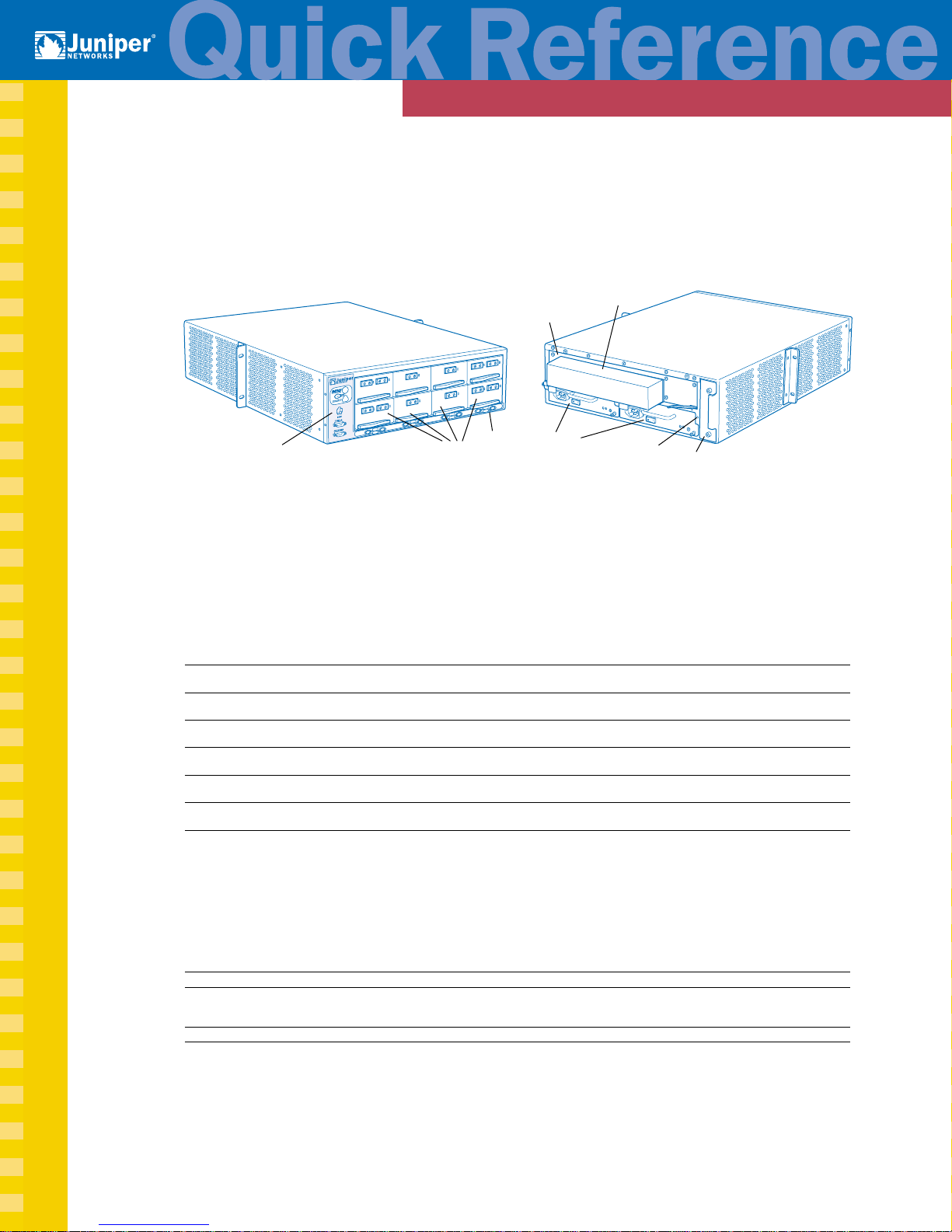
M5 and M10 Internet Backbone Routers
Forwarding
Engine
Routing Engine
cover
Board
1300
Craft interface
PICs
ESD
point
Power
supplies
ESD
point
Fan tray
Front View Rear View
M5 and M10 Routers Major Hardware Components
Component Quantity Function Redundant Field-replaceable Button
Forwarding Engine 1 Connects PICs to router components, – Requires router –
Board (FEB) houses shared memory shutdown
Physical Interface Cards 1–4
(PICs) 1–8
Routing Engine 1 Handles routing protocols, maintains – Requires router –
Power supplies 2 AC or Distributes voltages to components Yes Hot-removable –
Cooling system 1 fan tray Cools router components Yes Hot-removable –
Craft interface 1 Displays status and allows you to take – – –
Hot-removable and hot-insertable—Can remove and replace without powering down the router or disrupting routing functions.
Hot-pluggable—Can remove without powering down the router, but the routing and forwarding functions are interrupted until the replacement
component is installed.
M5 router
M10 router
2 DC Hot-insertable
(3 fans) Hot-insertable
Provides interfaces to various network media – Hot-removable Yes
Hot-insertable
routing tables shutdown
PICs offline
Offline
1302
M5 and M10 Routers Physical Specifications
Dimensions 5.25 in. (13.3 cm) high x 17.4 in. (44.2 cm) wide x 24 in. (61 cm) deep
Weight 57 lb (25.8 kg) minimum configuration
Required clearances 24 in. (61 cm) front and rear; 6 in. (15.2 cm) each side
Hardware JUNOS Release 4.3
61 lb (27.6 kg) maximum configuration,
65 lb (29.5 kg) maximum configuration,
M5 router
M10 router
Page 2

M5 and M10 Internet Backbone Routers
M5 and M10 Routers Power Supply Specifications
Specification AC DC
Maximum power consumption 434 W 434 W
Input voltage 100 through 264 VAC operating range –42.5 through –72 VDC operating range
Input line frequency 47 through 63 Hz, autoranging –
Input current rating 8 A @ 100 VAC; 4 A @ 240 VAC 13.5 A @ –48 VDC (typical)
Output voltages +1.5 V; +2.5 V; +3.3 V; +5 V; +12 V +1.5 V; +2.5 V; +3.3 V; +5 V; +12 V
Power and grounding cords and cables Country-specific; see M5 and M10 Internet 12 AWG wire cables attaching to
M5 and M10 Routers LEDs
Component LED Location
PICs 1 LED per port, with 4 states: Red, Green, Amber, Off PIC faceplate
Power supplies Blue OUTPUT OK Power supply faceplate
Alarm LEDs
Red alarm Large circular red Craft interface
Yellow alarm Large triangular amber Craft interface
Red alarms occur when the router is started if no device is physically connected to the management fxp0 interface or if two power supplies are
physically installed but only one is switched on.
Backbone Router Hardware Installation Guide quick-connect terminals; grounding
cable attaches to single-hole cable lug
Taking Components Offline
Component Procedure
PIC 1. Press the PIC offline button, located on the PIC faceplate.
2. Press and hold the button until the PIC LED lights red (about 5 seconds).
3. Press and hold the offline button again after installing the replacement PIC to bring the PIC online.
Page 3

M5 and M10 Internet Backbone Routers
JUNOS
software
System
management
processes
Routing
protocols
Control
functions
System processes
Operating system
Kernel
Intel-based PCI platform
1164
System Architecture
The router has two major architectural components: The Routing
Engine, which provides Layer 3 routing services and network
management; and the Packet Forwarding Engine, which provides
packet switching, route lookups, and packet forwarding. The
Routing Engine and Packet Forwarding Engine operate
independently, but constantly communicate through a 100-Mbps
link, as illustrated in the figure at the right.
Packet Flow through the
Packet Forwarding Engine
To ensure efficient packet flow through
the system, data packet forwarding is
handled by ASICs on the hardware
components. The figure at the right
shows the sequence of packet flow
through the Packet Forwarding Engine.
Packet
in
Packet
out
Controller
Controller
= ASIC
PIC
PIC
Packets
in
Midplane
I/O
Manager
Routing Engine
100-Mbps link
Packet Forwarding
Engine
FEB
Distributed
Buffer
Manager
Distributed
Buffer
Manager
Internet
Processor
II
Packets
out
1244
Routing
Engine
1335
Routing Engine Architecture
The Routing Engine handles all the routing protocol
processes as well as processes controlling
interfaces, router components, system
management, and user access. These processes run
on top of a kernel that interacts with the Packet
Forwarding Engine.
Control Packet Handling
The Routing Engine constructs and maintains routing
tables, and derives a table of active routes, called the
forwarding table, from the routing tables. The forwarding
table is then copied into the Packet Forwarding Engine.
Forwarding table
updates
Packets
in
Routing protocol
process
Routing Engine
Forwarding table
Packet Forwarding
Engine
Routing protocol
packets from network
Packets
out
1240
Page 4

M5 and M10 Internet Backbone Routers
General Safety Guidelines
■ Only trained and qualified personnel should install or replace the router.
■ Perform only the procedures described in the M5 and M10 Internet Backbone Routers Hardware Installation
Guide. Other services should be performed by authorized service personnel only.
■ For protection against shock hazard, verify that all power cables are disconnected before servicing the
router.
■ Before installing the router, read the guidelines in the “Prepare the Site” section of the M5 and M10 Internet
Backbone Routers Hardware Installation Guide to make sure that the site meets power, environmental, and
clearance requirements for the router.
■ Manually installing the router requires two people to lift the chassis and a third person to secure the
mounting screws. To prevent injury, keep your back straight and lift with your legs, not your back. Do not
attempt to lift the chassis with the handles on the power supplies.
■ Do not work on the router or connect or disconnect cables during electrical storms.
■ Never install electrical jacks in wet locations unless the jacks are specifically designed for wet
environments.
■ Operate the router only when the grounding wire is connected.
■ Use copper conductors only.
■ Avoid touching uninsulated electrical wires or terminals that have not been disconnected from their power
source. Doing so could cause electrical shock.
■ Do not open or remove chassis covers or sheet metal parts when instructions are not provided in the
M5 and M10 Internet Backbone Routers Hardware Installation Guide. Doing so could cause severe electrical
shock.
■ Do not push or force any objects through any of the openings in the chassis frame. Doing so could result
in electrical shock or fire.
■ Avoid spilling liquid into the router chassis or onto any router components. Doing so could cause electrical
shock or damage the router.
■ Before working on equipment that is connected to power lines, remove jewelry, including rings, necklaces,
and watches. Metal objects heat up when connected to power and ground and can cause serious burns or
weld the metal object to the terminals.
■ Failure to observe these safety warnings could result in serious physical injury.
Agency Approvals
Category Approval
Safety
EMI
Immunity
NEBS Designed to meet the following standards:
ETSI ■ ETS-300386-2 Switching Equipment
www.juniper.net
Juniper Networks is a registered trademark of Juniper Networks, Inc. Internet Processor, Internet Processor II, JUNOS, JUNOScript, M5, M10, M20, M40, and M160
are trademarks of Juniper Networks, Inc. All other trademarks, service marks, registered trademarks, or registered service marks may be the property of their
respective owners. All specifications are subject to change without notice. Copyright © 2001, Juniper Networks, Inc. All rights reserved. Printed in USA.
■ CSA C22.2 No. 950
■ UL 1950
■ EN 60950, Safety of Information Technology Equipment
■ EN 60825-1 Safety of Laser Products–Part 1: Equipment Classification, Requirements and User’s Guide
■ EN 60825-2 Safety of Laser Products–Part 2: Safety of Optical Fibre Communication Systems
■ AS 3548 Class A (Australia)
■ EN 55022 Class A emissions (Europe)
■ FCC Class A (USA)
■ VCCI Class A (Japan)
■ EN 61000-3-2 Power Line Harmonics
■ EN 61000-4-2 ESD
■ EN 61000-4-3 Radiated Immunity
■ EN 61000-4-4 EFT
■ EN 61000-4-5 Surge
■ EN 61000-4-6 Low Frequency Common Immunity
■ EN 61000-4-11 Voltage Dips and Sags
■ GR-63-Core: NEBS, Physical Protection
■ GR-1089-Core: EMC and Electrical Safety for Network Telecommunications Equipment
■ SR-3580 NEBS Criteria Levels (Level 3 Compliance)
For support issues, contact the Juniper Networks Technical Assistance Center (JTAC) at 1-888-314-JTAC
(within the United States) or 408-745-2121 (from outside the United States). For other contact
information, refer to www.juniper.net/contactus.html.
 Loading...