

Page 1

M320 Multiservice Edge Router Hardware Guide
Modified: 2015-05-20
Copyright © 2015, Juniper Networks, Inc.
Page 2

Juniper Networks, Inc.
1133 Innovation Way
Sunnyvale, California 94089
USA
408-745-2000
www.juniper.net
Copyright © 2015, Juniper Networks, Inc. All rights reserved.
Juniper Networks, Junos, Steel-Belted Radius, NetScreen, and ScreenOS are registered trademarks of Juniper Networks, Inc. in the United
States and other countries. The Juniper Networks Logo, the Junos logo, and JunosE are trademarks of Juniper Networks, Inc. All other
trademarks, service marks, registered trademarks, or registered service marks are the property of their respective owners.
Juniper Networks assumes no responsibility for any inaccuracies in this document. Juniper Networks reserves the right to change, modify,
transfer, or otherwise revise this publication without notice.
M320 Multiservice Edge Router Hardware Guide
Copyright © 2015, Juniper Networks, Inc.
All rights reserved.
The information in this document is current as of the date on the title page.
YEAR 2000 NOTICE
Juniper Networks hardware and software products are Year 2000 compliant. Junos OS has no known time-related limitations through the
year 2038. However, the NTP application is known to have some difficulty in the year 2036.
END USER LICENSE AGREEMENT
The Juniper Networks product that is the subject of this technical documentation consists of (or is intended for use with) Juniper Networks
software. Use of such software is subject to the terms and conditions of the End User License Agreement (“EULA”) posted at
http://www.juniper.net/support/eula.html. By downloading, installing or using such software, you agree to the terms and conditions of
that EULA.
Copyright © 2015, Juniper Networks, Inc.ii
Page 3

Table of Contents
About the Documentation . . . . . . . . . . . . . . . . . . . . . . . . . . . . . . . . . . . . . . . . . . . xxiii
Documentation and Release Notes . . . . . . . . . . . . . . . . . . . . . . . . . . . . . . . . xxiii
Supported Platforms . . . . . . . . . . . . . . . . . . . . . . . . . . . . . . . . . . . . . . . . . . . xxiii
Documentation Conventions . . . . . . . . . . . . . . . . . . . . . . . . . . . . . . . . . . . . . xxiii
Documentation Feedback . . . . . . . . . . . . . . . . . . . . . . . . . . . . . . . . . . . . . . . . xxv
Requesting Technical Support . . . . . . . . . . . . . . . . . . . . . . . . . . . . . . . . . . . . xxvi
Self-Help Online Tools and Resources . . . . . . . . . . . . . . . . . . . . . . . . . . xxvi
Opening a Case with JTAC . . . . . . . . . . . . . . . . . . . . . . . . . . . . . . . . . . . . xxvi
Part 1 Overview
Chapter 1 System Overview . . . . . . . . . . . . . . . . . . . . . . . . . . . . . . . . . . . . . . . . . . . . . . . . . . . 3
M320 Router Description . . . . . . . . . . . . . . . . . . . . . . . . . . . . . . . . . . . . . . . . . . . . . . 3
M320 Component Redundancy . . . . . . . . . . . . . . . . . . . . . . . . . . . . . . . . . . . . . . . . 4
Chapter 2 M320 Router Release Notes . . . . . . . . . . . . . . . . . . . . . . . . . . . . . . . . . . . . . . . . . 5
Outstanding Issues with the M320 Router . . . . . . . . . . . . . . . . . . . . . . . . . . . . . . . . 5
Errata with the M320 Router Documentation . . . . . . . . . . . . . . . . . . . . . . . . . . . . . . 5
Chapter 3 Chassis Components and Descriptions . . . . . . . . . . . . . . . . . . . . . . . . . . . . . . . . 7
M320 Chassis Description . . . . . . . . . . . . . . . . . . . . . . . . . . . . . . . . . . . . . . . . . . . . . 7
M320 Midplane Description . . . . . . . . . . . . . . . . . . . . . . . . . . . . . . . . . . . . . . . . . . . 10
M320 Fuses . . . . . . . . . . . . . . . . . . . . . . . . . . . . . . . . . . . . . . . . . . . . . . . . . . . . . . . . 12
M320 Cable Management System Description . . . . . . . . . . . . . . . . . . . . . . . . . . . . 12
M320 Connector Interface Panel (CIP) Description . . . . . . . . . . . . . . . . . . . . . . . . 13
CIP Components . . . . . . . . . . . . . . . . . . . . . . . . . . . . . . . . . . . . . . . . . . . . . . . . 13
Routing Engine Ports . . . . . . . . . . . . . . . . . . . . . . . . . . . . . . . . . . . . . . . . . . . . . 14
Alarm Relay Contacts . . . . . . . . . . . . . . . . . . . . . . . . . . . . . . . . . . . . . . . . . . . . 15
M320 Craft Interface Description . . . . . . . . . . . . . . . . . . . . . . . . . . . . . . . . . . . . . . . 15
M320 Craft Interface Alarm LEDs and ACO/LT Button . . . . . . . . . . . . . . . . . . . . . . 16
M320 Craft Interface LED Display and Navigation Buttons . . . . . . . . . . . . . . . . . . 16
M320 Craft Interface Host Subsystem LEDs . . . . . . . . . . . . . . . . . . . . . . . . . . . . . . 18
M320 Craft Interface FPC LEDs and Online/Offline Buttons . . . . . . . . . . . . . . . . . 18
M320 Craft Interface Power Supply LEDs . . . . . . . . . . . . . . . . . . . . . . . . . . . . . . . . 19
M320 Craft Interface SIB LEDs . . . . . . . . . . . . . . . . . . . . . . . . . . . . . . . . . . . . . . . . . 19
Chapter 4 Cooling System Components and Descriptions . . . . . . . . . . . . . . . . . . . . . . . . 21
M320 Cooling System Description . . . . . . . . . . . . . . . . . . . . . . . . . . . . . . . . . . . . . . 21
Chapter 5 Host Subsystem Components and Descriptions . . . . . . . . . . . . . . . . . . . . . . 23
M320 Host Subsystem Description . . . . . . . . . . . . . . . . . . . . . . . . . . . . . . . . . . . . . 23
M320 Routing Engine Description . . . . . . . . . . . . . . . . . . . . . . . . . . . . . . . . . . . . . . 24
iiiCopyright © 2015, Juniper Networks, Inc.
Page 4

M320 Multiservice Edge Router Hardware Guide
M320 Routing Engine 600 Description . . . . . . . . . . . . . . . . . . . . . . . . . . . . . . . . . . 25
M320 Routing Engine 1600 Description . . . . . . . . . . . . . . . . . . . . . . . . . . . . . . . . . 26
M320 Routing Engine 2000 Description . . . . . . . . . . . . . . . . . . . . . . . . . . . . . . . . . 27
M320 RE-A-1800 Routing Engine Description . . . . . . . . . . . . . . . . . . . . . . . . . . . . 28
Routing Engine Components . . . . . . . . . . . . . . . . . . . . . . . . . . . . . . . . . . . . . . 28
Routing Engine Boot Sequence . . . . . . . . . . . . . . . . . . . . . . . . . . . . . . . . . . . . 30
RE-A-1800 Routing Engine LEDs . . . . . . . . . . . . . . . . . . . . . . . . . . . . . . . . . . . . . . . 31
Routing Engine Specifications . . . . . . . . . . . . . . . . . . . . . . . . . . . . . . . . . . . . . . . . . 31
Supported Routing Engines by Router . . . . . . . . . . . . . . . . . . . . . . . . . . . . . . . . . . 34
M7i Routing Engines . . . . . . . . . . . . . . . . . . . . . . . . . . . . . . . . . . . . . . . . . . . . . 34
M10i Routing Engines . . . . . . . . . . . . . . . . . . . . . . . . . . . . . . . . . . . . . . . . . . . . 35
M40e Routing Engines . . . . . . . . . . . . . . . . . . . . . . . . . . . . . . . . . . . . . . . . . . . 35
M120 Routing Engines . . . . . . . . . . . . . . . . . . . . . . . . . . . . . . . . . . . . . . . . . . . . 36
M320 Routing Engines . . . . . . . . . . . . . . . . . . . . . . . . . . . . . . . . . . . . . . . . . . . 36
MX104 Routing Engines . . . . . . . . . . . . . . . . . . . . . . . . . . . . . . . . . . . . . . . . . . 37
MX240 Routing Engines . . . . . . . . . . . . . . . . . . . . . . . . . . . . . . . . . . . . . . . . . . 37
MX480 Routing Engines . . . . . . . . . . . . . . . . . . . . . . . . . . . . . . . . . . . . . . . . . . 38
MX960 Routing Engines . . . . . . . . . . . . . . . . . . . . . . . . . . . . . . . . . . . . . . . . . . 39
MX2010 Routing Engines . . . . . . . . . . . . . . . . . . . . . . . . . . . . . . . . . . . . . . . . . 39
MX2020 Routing Engines . . . . . . . . . . . . . . . . . . . . . . . . . . . . . . . . . . . . . . . . . 40
PTX3000 Routing Engines . . . . . . . . . . . . . . . . . . . . . . . . . . . . . . . . . . . . . . . . 40
PTX5000 Routing Engines . . . . . . . . . . . . . . . . . . . . . . . . . . . . . . . . . . . . . . . 40
T320 Routing Engines . . . . . . . . . . . . . . . . . . . . . . . . . . . . . . . . . . . . . . . . . . . . 41
T640 Routing Engines . . . . . . . . . . . . . . . . . . . . . . . . . . . . . . . . . . . . . . . . . . . . 41
T1600 Routing Engines . . . . . . . . . . . . . . . . . . . . . . . . . . . . . . . . . . . . . . . . . . . 42
T4000 Routing Engines . . . . . . . . . . . . . . . . . . . . . . . . . . . . . . . . . . . . . . . . . . 43
TX Matrix Routing Engines . . . . . . . . . . . . . . . . . . . . . . . . . . . . . . . . . . . . . . . . 44
TX Matrix Plus Routing Engines . . . . . . . . . . . . . . . . . . . . . . . . . . . . . . . . . . . . 44
TX Matrix Plus (with 3D SIBs) Routing Engines . . . . . . . . . . . . . . . . . . . . . . . 44
M320 Control Board (CB) Description . . . . . . . . . . . . . . . . . . . . . . . . . . . . . . . . . . 45
M320 Control Board (CB) LEDs . . . . . . . . . . . . . . . . . . . . . . . . . . . . . . . . . . . . . . . 46
Chapter 6 Line Card Components and Descriptions . . . . . . . . . . . . . . . . . . . . . . . . . . . . . 49
M320 Flexible PIC Concentrator (FPC) Description . . . . . . . . . . . . . . . . . . . . . . . . 49
M320 FPC Terminology . . . . . . . . . . . . . . . . . . . . . . . . . . . . . . . . . . . . . . . . . . . . . . 53
M320 FPCs Supported . . . . . . . . . . . . . . . . . . . . . . . . . . . . . . . . . . . . . . . . . . . . . . . 53
M320 PIC Description . . . . . . . . . . . . . . . . . . . . . . . . . . . . . . . . . . . . . . . . . . . . . . . 54
M320 PICs Supported . . . . . . . . . . . . . . . . . . . . . . . . . . . . . . . . . . . . . . . . . . . . . . . 55
M320 End-of-Life PICs Supported . . . . . . . . . . . . . . . . . . . . . . . . . . . . . . . . . . . . . 64
M320 PIC Combination Limitations . . . . . . . . . . . . . . . . . . . . . . . . . . . . . . . . . . . . 66
M320 PIC/FPC Compatibility . . . . . . . . . . . . . . . . . . . . . . . . . . . . . . . . . . . . . . . . . 66
PIC/FPC Compatibility (Type 1 FPCs and Type 1 PICs) . . . . . . . . . . . . . . . . . . 67
PIC/FPC Compatibility (Type 2 FPCs and Type 2 PICs) . . . . . . . . . . . . . . . . . 70
PIC/FPC Compatibility (Type 3 FPCs and Type 3 PICs) . . . . . . . . . . . . . . . . . . 71
Chapter 7 Power System Components and Descriptions . . . . . . . . . . . . . . . . . . . . . . . . 73
M320 Power System Description . . . . . . . . . . . . . . . . . . . . . . . . . . . . . . . . . . . . . . . 73
M320 AC Power Supplies Description . . . . . . . . . . . . . . . . . . . . . . . . . . . . . . . . . . . 73
Copyright © 2015, Juniper Networks, Inc.iv
Page 5

Table of Contents
M320 DC Power Supplies Description . . . . . . . . . . . . . . . . . . . . . . . . . . . . . . . . . . . 74
Nonisolated DC Power Supply . . . . . . . . . . . . . . . . . . . . . . . . . . . . . . . . . . . . . 75
Isolated DC Power Supply . . . . . . . . . . . . . . . . . . . . . . . . . . . . . . . . . . . . . . . . . 75
Components Powered by Each Power Supply Slot . . . . . . . . . . . . . . . . . . . . . 75
DC Power Supply Load Sharing and Fault Tolerance . . . . . . . . . . . . . . . . . . . 76
M320 Power Supply LEDs . . . . . . . . . . . . . . . . . . . . . . . . . . . . . . . . . . . . . . . . . . . . 76
Chapter 8 Switch Fabric Components and Descriptions . . . . . . . . . . . . . . . . . . . . . . . . . 79
M320 SIB Description . . . . . . . . . . . . . . . . . . . . . . . . . . . . . . . . . . . . . . . . . . . . . . . 79
M320 Performance for Different SIB Configurations . . . . . . . . . . . . . . . . . . . . . . . 80
M320 SIB LEDs . . . . . . . . . . . . . . . . . . . . . . . . . . . . . . . . . . . . . . . . . . . . . . . . . . . . . 81
Part 2 Site Planning, Preparation, and Specifications
Chapter 9 Preparation Overview . . . . . . . . . . . . . . . . . . . . . . . . . . . . . . . . . . . . . . . . . . . . . 85
M320 Site Preparation Checklist Requirements . . . . . . . . . . . . . . . . . . . . . . . . . . . 85
M320 Router Physical Specifications . . . . . . . . . . . . . . . . . . . . . . . . . . . . . . . . . . . 86
Rack Requirements for the M320 Router . . . . . . . . . . . . . . . . . . . . . . . . . . . . . . . . 87
M320 Cabinet Size and Clearance Requirements . . . . . . . . . . . . . . . . . . . . . . . . . 88
M320 Cabinet Airflow Requirements . . . . . . . . . . . . . . . . . . . . . . . . . . . . . . . . . . . 90
M320 Clearance Requirements . . . . . . . . . . . . . . . . . . . . . . . . . . . . . . . . . . . . . . . . 91
M320 Environmental Specifications . . . . . . . . . . . . . . . . . . . . . . . . . . . . . . . . . . . . 93
M320 Chassis Grounding Cable and Lug Specifications . . . . . . . . . . . . . . . . . . . . 94
Site Electrical Wiring Guidelines for Juniper Networks Devices . . . . . . . . . . . . . . . 95
Distance Limitations for Signaling . . . . . . . . . . . . . . . . . . . . . . . . . . . . . . . . . . 95
Radio Frequency Interference . . . . . . . . . . . . . . . . . . . . . . . . . . . . . . . . . . . . . 95
Electromagnetic Compatibility . . . . . . . . . . . . . . . . . . . . . . . . . . . . . . . . . . . . 95
M320 Power Requirements . . . . . . . . . . . . . . . . . . . . . . . . . . . . . . . . . . . . . . . . . . . 96
M320 RJ-48 Connector Pinouts for the Control Board External Clock Inputs . . . 98
M320 Fuse Specifications . . . . . . . . . . . . . . . . . . . . . . . . . . . . . . . . . . . . . . . . . . . . 99
Chapter 10 AC Power Specifications . . . . . . . . . . . . . . . . . . . . . . . . . . . . . . . . . . . . . . . . . . . 101
M320 AC Power Electrical Specifications . . . . . . . . . . . . . . . . . . . . . . . . . . . . . . . . 101
M320 AC Power Cord Specifications . . . . . . . . . . . . . . . . . . . . . . . . . . . . . . . . . . . 102
Chapter 11 DC Power Specifications . . . . . . . . . . . . . . . . . . . . . . . . . . . . . . . . . . . . . . . . . . 105
M320 DC Power Electrical Specifications . . . . . . . . . . . . . . . . . . . . . . . . . . . . . . . 105
DC Power System Electrical Specifications . . . . . . . . . . . . . . . . . . . . . . . . . . 105
Nonisolated DC Power Supply Electrical Specifications . . . . . . . . . . . . . . . . 106
Isolated DC Power Supply Electrical Specifications . . . . . . . . . . . . . . . . . . . 106
M320 DC Power Cable Specifications . . . . . . . . . . . . . . . . . . . . . . . . . . . . . . . . . . 107
M320 DC Power Distribution . . . . . . . . . . . . . . . . . . . . . . . . . . . . . . . . . . . . . . . . . 109
DC Power Circuit Breaker for M320 Routers . . . . . . . . . . . . . . . . . . . . . . . . . . . . . 109
Chapter 12 Network Cable and Transceiver Planning . . . . . . . . . . . . . . . . . . . . . . . . . . . . . 111
Understanding Fiber-Optic Cable Signal Loss, Attenuation, and Dispersion . . . . . 111
Signal Loss in Multimode and Single-Mode Fiber-Optic Cable . . . . . . . . . . . . 111
Attenuation and Dispersion in Fiber-Optic Cable . . . . . . . . . . . . . . . . . . . . . . 111
Calculating Power Budget and Power Margin for Fiber-Optic Cables . . . . . . . . . . 112
Calculating Power Budget for Fiber-Optic Cable . . . . . . . . . . . . . . . . . . . . . . 112
Calculating Power Margin for Fiber-Optic Cable . . . . . . . . . . . . . . . . . . . . . . . 113
vCopyright © 2015, Juniper Networks, Inc.
Page 6

M320 Multiservice Edge Router Hardware Guide
Chapter 13 Management Cable and Transceiver Specifications and Pinouts . . . . . . . . 115
M320 Routing Engine Interface Cable and Wire Specifications . . . . . . . . . . . . . . . 115
M320 RJ-45 Connector Pinouts for the Routing Engine ETHERNET Port . . . . . . . 116
M320 DB-9 Connector Pinouts for the Routing Engine AUX and CONSOLE
Ports . . . . . . . . . . . . . . . . . . . . . . . . . . . . . . . . . . . . . . . . . . . . . . . . . . . . . . . . . 116
Part 3 Initial Installation and Configuration
Chapter 14 Installation Overview . . . . . . . . . . . . . . . . . . . . . . . . . . . . . . . . . . . . . . . . . . . . . . 121
M320 Router Installation Summary . . . . . . . . . . . . . . . . . . . . . . . . . . . . . . . . . . . . 121
Chapter 15 Unpacking the M320 . . . . . . . . . . . . . . . . . . . . . . . . . . . . . . . . . . . . . . . . . . . . . . 123
Tools and Parts Required to Unpack the M320 Router . . . . . . . . . . . . . . . . . . . . . 123
Unpacking the M320 Router . . . . . . . . . . . . . . . . . . . . . . . . . . . . . . . . . . . . . . . . . . 123
Verifying the M320 Router Parts Received . . . . . . . . . . . . . . . . . . . . . . . . . . . . . . . 125
Chapter 16 Installing the Mounting Hardware . . . . . . . . . . . . . . . . . . . . . . . . . . . . . . . . . . 127
Installing the M320 Mounting Hardware for a Four-Post Rack or Cabinet . . . . . . 127
Installing Cage Nuts (If Needed) for M320 Four-Post Racks or Cabinets . . . 127
Installing the Large Mounting Shelf for M320 Four-Post Racks or
Installing the Small Mounting Shelf for M320 Four-Post Racks or
Removing the Adjustable Center-Mounting Brackets for M320 Four-Post
Installing the M320 Mounting Hardware for Open-Frame Racks . . . . . . . . . . . . . 130
Installing Cage Nuts (If Needed) for M320 Open Frame Racks . . . . . . . . . . . 131
Installing the Large Mounting Shelf for the M320 Open-Frame Racks . . . . . 132
Installing the Small Mounting Shelf for the M320 Open-Frame Racks . . . . . 132
Moving the Adjustable Center-Mounting Brackets for M320 Open-Frame
Chapter 17 Installing the M320 With a Mechanical Lift . . . . . . . . . . . . . . . . . . . . . . . . . . 135
Overview of Installing the M320 Chassis Using a Mechanical Lift . . . . . . . . . . . . 135
Tools Required to Install the M320 Chassis Using a Mechanical Lift . . . . . . . . . . 136
Installing the M320 Chassis Using a Mechanical Lift . . . . . . . . . . . . . . . . . . . . . . 136
Attaching the Installation Handle to the M320 Chassis . . . . . . . . . . . . . . . . 136
Mounting the M320 Chassis Using a Mechanical Lift . . . . . . . . . . . . . . . . . . 138
Removing the M320 Installation Handle and Reinstalling the Power
Installing the M320 Cable Guards . . . . . . . . . . . . . . . . . . . . . . . . . . . . . . . . . . . . . 140
Chapter 18 Installing the M320 Without a Mechanical Lift . . . . . . . . . . . . . . . . . . . . . . . 143
Tools and Parts Required to Install the M320 Chassis Without a Mechanical
Lift . . . . . . . . . . . . . . . . . . . . . . . . . . . . . . . . . . . . . . . . . . . . . . . . . . . . . . . . . . 143
Removing M320 Components from the Chassis . . . . . . . . . . . . . . . . . . . . . . . . . . 143
Removing the M320 Power Supplies . . . . . . . . . . . . . . . . . . . . . . . . . . . . . . . 144
Removing the M320 SIBs . . . . . . . . . . . . . . . . . . . . . . . . . . . . . . . . . . . . . . . . 145
Removing the M320 CBs . . . . . . . . . . . . . . . . . . . . . . . . . . . . . . . . . . . . . . . . . 146
Removing the M320 Rear Fan Tray . . . . . . . . . . . . . . . . . . . . . . . . . . . . . . . . . 146
Cabinets . . . . . . . . . . . . . . . . . . . . . . . . . . . . . . . . . . . . . . . . . . . . . . . . . . 128
Cabinets . . . . . . . . . . . . . . . . . . . . . . . . . . . . . . . . . . . . . . . . . . . . . . . . . . 129
Racks or Cabinets . . . . . . . . . . . . . . . . . . . . . . . . . . . . . . . . . . . . . . . . . . . 129
Racks . . . . . . . . . . . . . . . . . . . . . . . . . . . . . . . . . . . . . . . . . . . . . . . . . . . . . 133
Supplies . . . . . . . . . . . . . . . . . . . . . . . . . . . . . . . . . . . . . . . . . . . . . . . . . . 139
Copyright © 2015, Juniper Networks, Inc.vi
Page 7

Table of Contents
Removing the M320 Cable Management System . . . . . . . . . . . . . . . . . . . . . 148
Removing the M320 Front Fan Trays . . . . . . . . . . . . . . . . . . . . . . . . . . . . . . . 148
Removing the M320 FPCs . . . . . . . . . . . . . . . . . . . . . . . . . . . . . . . . . . . . . . . . 149
Installing the M320 Chassis in the Rack Manually . . . . . . . . . . . . . . . . . . . . . . . . . 151
Reinstalling M320 Components in the Chassis . . . . . . . . . . . . . . . . . . . . . . . . . . . 153
Reinstalling an M320 Rear Fan Tray . . . . . . . . . . . . . . . . . . . . . . . . . . . . . . . . 154
Reinstalling the M320 CBs . . . . . . . . . . . . . . . . . . . . . . . . . . . . . . . . . . . . . . . 155
Reinstalling the M320 SIBs . . . . . . . . . . . . . . . . . . . . . . . . . . . . . . . . . . . . . . . 155
Reinstalling the M320 Power Supplies . . . . . . . . . . . . . . . . . . . . . . . . . . . . . . 156
Reinstalling the M320 FPCs . . . . . . . . . . . . . . . . . . . . . . . . . . . . . . . . . . . . . . 157
Reinstalling M320 Front Fan Trays . . . . . . . . . . . . . . . . . . . . . . . . . . . . . . . . . 158
Reinstalling the M320 Cable Management System . . . . . . . . . . . . . . . . . . . . 159
Installing the M320 Cable Guards . . . . . . . . . . . . . . . . . . . . . . . . . . . . . . . . . . . . . 159
Chapter 19 Connecting the M320 to Ground . . . . . . . . . . . . . . . . . . . . . . . . . . . . . . . . . . . . 161
Tools and Parts Required to Ground the M320 Router . . . . . . . . . . . . . . . . . . . . . 161
Connecting the M320 Router Grounding Cable . . . . . . . . . . . . . . . . . . . . . . . . . . . 161
Chapter 20 Connecting the M320 to External Devices . . . . . . . . . . . . . . . . . . . . . . . . . . . 163
Tools and Parts Required for M320 Router Connections . . . . . . . . . . . . . . . . . . . 163
Overview of Connecting the M320 Router to Management and Alarm
Devices . . . . . . . . . . . . . . . . . . . . . . . . . . . . . . . . . . . . . . . . . . . . . . . . . . . . . . . 164
Connecting the M320 Router to a Management Console or Auxiliary Device . . . 165
Connecting the M320 Router to a Network for Out-of-Band Management . . . . 166
Connecting the M320 Router to an External Alarm-Reporting Device . . . . . . . . . 168
Connecting the M320 Router to an External Clocking Device . . . . . . . . . . . . . . . 168
Connecting PIC Cables to the M320 Router . . . . . . . . . . . . . . . . . . . . . . . . . . . . . 169
Chapter 21 Providing Power to the M320 . . . . . . . . . . . . . . . . . . . . . . . . . . . . . . . . . . . . . . 173
Connecting Power to an AC-Powered M320 Router . . . . . . . . . . . . . . . . . . . . . . . 173
Connecting Power to a DC-Powered M320 Router . . . . . . . . . . . . . . . . . . . . . . . . 174
Powering On the M320 Router . . . . . . . . . . . . . . . . . . . . . . . . . . . . . . . . . . . . . . . . 176
Powering Off the M320 Router . . . . . . . . . . . . . . . . . . . . . . . . . . . . . . . . . . . . . . . . 178
Chapter 22 Configuring the Junos OS Software . . . . . . . . . . . . . . . . . . . . . . . . . . . . . . . . . 179
Initially Configuring the M320 Router . . . . . . . . . . . . . . . . . . . . . . . . . . . . . . . . . . . 179
Part 4 Installing and Replacing Components
Chapter 23 Overview of Installing and Replacing Components . . . . . . . . . . . . . . . . . . . 185
M320 Field Replaceable Units . . . . . . . . . . . . . . . . . . . . . . . . . . . . . . . . . . . . . . . . 185
Tools and Parts Required to Replace the M320 Hardware Components . . . . . . . 186
viiCopyright © 2015, Juniper Networks, Inc.
Page 8

M320 Multiservice Edge Router Hardware Guide
Chapter 24 Replacing Chassis Components . . . . . . . . . . . . . . . . . . . . . . . . . . . . . . . . . . . . 189
Replacing the M320 CIP . . . . . . . . . . . . . . . . . . . . . . . . . . . . . . . . . . . . . . . . . . . . . 189
Removing an M320 CIP . . . . . . . . . . . . . . . . . . . . . . . . . . . . . . . . . . . . . . . . . . 189
Installing an M320 CIP . . . . . . . . . . . . . . . . . . . . . . . . . . . . . . . . . . . . . . . . . . 190
Replacing the M320 Alarm Relay Wires . . . . . . . . . . . . . . . . . . . . . . . . . . . . . . . . . 192
Replacing an M320 Management Ethernet Cable . . . . . . . . . . . . . . . . . . . . . . . . 192
Replacing an M320 Console or Auxiliary Cable . . . . . . . . . . . . . . . . . . . . . . . . . . . 194
Removing an M320 Console or Auxiliary Cable . . . . . . . . . . . . . . . . . . . . . . . 194
Installing an M320 Console or Auxiliary Cable . . . . . . . . . . . . . . . . . . . . . . . . 195
Replacing an M320 Craft Interface . . . . . . . . . . . . . . . . . . . . . . . . . . . . . . . . . . . . . 197
Removing an M320 Craft Interface . . . . . . . . . . . . . . . . . . . . . . . . . . . . . . . . . 197
Installing an M320 Craft Interface . . . . . . . . . . . . . . . . . . . . . . . . . . . . . . . . . 198
Replacing an M320 Fuse . . . . . . . . . . . . . . . . . . . . . . . . . . . . . . . . . . . . . . . . . . . . 199
Chapter 25 Replacing Cooling System Components . . . . . . . . . . . . . . . . . . . . . . . . . . . . 203
Replacing an M320 Air Filter . . . . . . . . . . . . . . . . . . . . . . . . . . . . . . . . . . . . . . . . . 203
Removing an M320 Front Air Filter . . . . . . . . . . . . . . . . . . . . . . . . . . . . . . . . . 203
Installing an M320 Front Air Filter . . . . . . . . . . . . . . . . . . . . . . . . . . . . . . . . . 204
Removing an M320 Rear Air Filter . . . . . . . . . . . . . . . . . . . . . . . . . . . . . . . . . 205
Installing an M320 Rear Air Filter . . . . . . . . . . . . . . . . . . . . . . . . . . . . . . . . . . 207
Replacing an M320 Fan Tray . . . . . . . . . . . . . . . . . . . . . . . . . . . . . . . . . . . . . . . . . 208
Removing an M320 Front Fan Tray . . . . . . . . . . . . . . . . . . . . . . . . . . . . . . . . 208
Installing an M320 Front Fan Tray . . . . . . . . . . . . . . . . . . . . . . . . . . . . . . . . . . 210
Removing an M320 Rear Fan Tray . . . . . . . . . . . . . . . . . . . . . . . . . . . . . . . . . 210
Installing an M320 Rear Fan Tray . . . . . . . . . . . . . . . . . . . . . . . . . . . . . . . . . . . 211
Chapter 26 Replacing Host Subsystem Components . . . . . . . . . . . . . . . . . . . . . . . . . . . . 213
Taking the M320 Host Subsystem Offline . . . . . . . . . . . . . . . . . . . . . . . . . . . . . . . 213
Replacing an M320 Routing Engine . . . . . . . . . . . . . . . . . . . . . . . . . . . . . . . . . . . . 216
Removing an M320 Routing Engine . . . . . . . . . . . . . . . . . . . . . . . . . . . . . . . . 216
Installing an M320 Routing Engine . . . . . . . . . . . . . . . . . . . . . . . . . . . . . . . . . 217
Replacing a Solid-State Disk on an M320 RE-A-1800 Routing Engine . . . . . . . . 218
Removing an Solid-State Disk From an M320 RE-A-1800 Routing
Installing an Solid-State Disk on an M320 RE-A-1800 Routing Engine . . . . 219
Inserting or Removing a PC Card from an M320 Routing Engine . . . . . . . . . . . . . 219
Inserting a PC Card into an M320 Routing Engine . . . . . . . . . . . . . . . . . . . . . 220
Removing an M320 PC Card . . . . . . . . . . . . . . . . . . . . . . . . . . . . . . . . . . . . . . 221
Replacing a DIMM Module in an M320 Routing Engine . . . . . . . . . . . . . . . . . . . . . 221
Removing an M320 DIMM Module . . . . . . . . . . . . . . . . . . . . . . . . . . . . . . . . . 222
Installing an M320 DIMM Module . . . . . . . . . . . . . . . . . . . . . . . . . . . . . . . . . . 222
Replacing an M320 Control Board . . . . . . . . . . . . . . . . . . . . . . . . . . . . . . . . . . . . . 223
Removing an M320 Control Board . . . . . . . . . . . . . . . . . . . . . . . . . . . . . . . . . 223
Installing an M320 Control Board . . . . . . . . . . . . . . . . . . . . . . . . . . . . . . . . . . 225
Engine . . . . . . . . . . . . . . . . . . . . . . . . . . . . . . . . . . . . . . . . . . . . . . . . . . . . 219
Copyright © 2015, Juniper Networks, Inc.viii
Page 9

Table of Contents
Chapter 27 Replacing Line Card Components . . . . . . . . . . . . . . . . . . . . . . . . . . . . . . . . . . 227
Replacing an M320 FPC . . . . . . . . . . . . . . . . . . . . . . . . . . . . . . . . . . . . . . . . . . . . . 227
Removing an M320 FPC . . . . . . . . . . . . . . . . . . . . . . . . . . . . . . . . . . . . . . . . . 227
Installing an M320 FPC . . . . . . . . . . . . . . . . . . . . . . . . . . . . . . . . . . . . . . . . . 230
Replacing an M320 PIC . . . . . . . . . . . . . . . . . . . . . . . . . . . . . . . . . . . . . . . . . . . . . 233
Removing an M320 PIC . . . . . . . . . . . . . . . . . . . . . . . . . . . . . . . . . . . . . . . . . . 233
Installing an M320 PIC . . . . . . . . . . . . . . . . . . . . . . . . . . . . . . . . . . . . . . . . . . 235
Replacing M320 PIC Cables . . . . . . . . . . . . . . . . . . . . . . . . . . . . . . . . . . . . . . . . . . 237
Removing an M320 PIC Cable . . . . . . . . . . . . . . . . . . . . . . . . . . . . . . . . . . . . 238
Installing an M320 PIC Cable . . . . . . . . . . . . . . . . . . . . . . . . . . . . . . . . . . . . . 238
Replacing an M320 SFP . . . . . . . . . . . . . . . . . . . . . . . . . . . . . . . . . . . . . . . . . . . . 240
Removing an M320 SFP . . . . . . . . . . . . . . . . . . . . . . . . . . . . . . . . . . . . . . . . . 241
Installing an M320 SFP . . . . . . . . . . . . . . . . . . . . . . . . . . . . . . . . . . . . . . . . . . 242
Replacing an M320 XENPAK Module . . . . . . . . . . . . . . . . . . . . . . . . . . . . . . . . . . 243
Removing an M320 XENPAK Module . . . . . . . . . . . . . . . . . . . . . . . . . . . . . . . 243
Installing an M320 XENPAK Module . . . . . . . . . . . . . . . . . . . . . . . . . . . . . . . 245
Chapter 28 Replacing Power System Components . . . . . . . . . . . . . . . . . . . . . . . . . . . . . . 247
Replacing an M320 AC Power Supply . . . . . . . . . . . . . . . . . . . . . . . . . . . . . . . . . . 247
Removing an M320 AC Power Supply . . . . . . . . . . . . . . . . . . . . . . . . . . . . . . 247
Installing an M320 AC Power Supply . . . . . . . . . . . . . . . . . . . . . . . . . . . . . . . 248
Replacing an M320 DC Power Supply . . . . . . . . . . . . . . . . . . . . . . . . . . . . . . . . . . 250
Removing an M320 DC Power Supply . . . . . . . . . . . . . . . . . . . . . . . . . . . . . . 250
Installing an M320 DC Power Supply . . . . . . . . . . . . . . . . . . . . . . . . . . . . . . . 252
Replacing an M320 AC Power Supply Cord . . . . . . . . . . . . . . . . . . . . . . . . . . . . . 254
Replacing an M320 DC Power Supply Cable . . . . . . . . . . . . . . . . . . . . . . . . . . . . 255
Chapter 29 Replacing Switch Fabric Components . . . . . . . . . . . . . . . . . . . . . . . . . . . . . . 259
Replacing an M320 SIB . . . . . . . . . . . . . . . . . . . . . . . . . . . . . . . . . . . . . . . . . . . . . 259
Removing an M320 SIB . . . . . . . . . . . . . . . . . . . . . . . . . . . . . . . . . . . . . . . . . 259
Installing an M320 SIB . . . . . . . . . . . . . . . . . . . . . . . . . . . . . . . . . . . . . . . . . . 260
Part 5 Maintaining the Chassis and Components
Chapter 30 Routine Maintenance Procedures . . . . . . . . . . . . . . . . . . . . . . . . . . . . . . . . . . 265
Routine Maintenance Procedures for the M320 Router . . . . . . . . . . . . . . . . . . . . 265
Chapter 31 Maintaining Components and Cables . . . . . . . . . . . . . . . . . . . . . . . . . . . . . . . 267
Tools and Parts Required to Maintain the M320 Hardware Components . . . . . . 267
Maintaining the M320 Air Filters . . . . . . . . . . . . . . . . . . . . . . . . . . . . . . . . . . . . . . 267
Maintaining the M320 Fan Trays . . . . . . . . . . . . . . . . . . . . . . . . . . . . . . . . . . . . . . 268
Maintaining the M320 Host Subsystem . . . . . . . . . . . . . . . . . . . . . . . . . . . . . . . . 269
Maintaining M320 FPCs . . . . . . . . . . . . . . . . . . . . . . . . . . . . . . . . . . . . . . . . . . . . . 270
Holding and Storing M320 FPCs . . . . . . . . . . . . . . . . . . . . . . . . . . . . . . . . . . . . . . 272
Holding M320 FPCs . . . . . . . . . . . . . . . . . . . . . . . . . . . . . . . . . . . . . . . . . . . . . 272
Storing M320 FPCs . . . . . . . . . . . . . . . . . . . . . . . . . . . . . . . . . . . . . . . . . . . . . 275
Maintaining M320 PICs and PIC Cables . . . . . . . . . . . . . . . . . . . . . . . . . . . . . . . . 276
Maintaining the M320 Power Supplies . . . . . . . . . . . . . . . . . . . . . . . . . . . . . . . . . 278
Maintaining the M320 SIBs . . . . . . . . . . . . . . . . . . . . . . . . . . . . . . . . . . . . . . . . . . 279
ixCopyright © 2015, Juniper Networks, Inc.
Page 10

M320 Multiservice Edge Router Hardware Guide
Part 6 Troubleshooting Hardware
Chapter 32 Troubleshooting Components . . . . . . . . . . . . . . . . . . . . . . . . . . . . . . . . . . . . . 283
M320 Troubleshooting Resources Overview . . . . . . . . . . . . . . . . . . . . . . . . . . . . 283
M320 LED Overview . . . . . . . . . . . . . . . . . . . . . . . . . . . . . . . . . . . . . . . . . . . . . . . 284
Craft Interface LEDs . . . . . . . . . . . . . . . . . . . . . . . . . . . . . . . . . . . . . . . . . . . . 284
Component LEDs . . . . . . . . . . . . . . . . . . . . . . . . . . . . . . . . . . . . . . . . . . . . . . 284
M320 Chassis and Interface Alarm Messages . . . . . . . . . . . . . . . . . . . . . . . . . . . 285
Troubleshooting the M320 Cooling System . . . . . . . . . . . . . . . . . . . . . . . . . . . . . 287
Troubleshooting the M320 FPCs . . . . . . . . . . . . . . . . . . . . . . . . . . . . . . . . . . . . . . 289
Troubleshooting the M320 Fuses . . . . . . . . . . . . . . . . . . . . . . . . . . . . . . . . . . . . . 290
Troubleshooting the M320 PICs . . . . . . . . . . . . . . . . . . . . . . . . . . . . . . . . . . . . . . . 291
Troubleshooting the M320 Power System . . . . . . . . . . . . . . . . . . . . . . . . . . . . . . 292
Part 7 Contacting Customer Support and Returning the Chassis or
Components
Chapter 33 Contacting Customer Support . . . . . . . . . . . . . . . . . . . . . . . . . . . . . . . . . . . . . 297
Contacting Customer Support . . . . . . . . . . . . . . . . . . . . . . . . . . . . . . . . . . . . . . . . 297
Chapter 34 Locating Component Serial Numbers . . . . . . . . . . . . . . . . . . . . . . . . . . . . . . 299
Locating M320 Component Serial Numbers Using the CLI . . . . . . . . . . . . . . . . . 299
Locating the M320 Chassis Serial Number Label . . . . . . . . . . . . . . . . . . . . . . . . 300
Locating the M320 CIP Serial Number Label . . . . . . . . . . . . . . . . . . . . . . . . . . . . 300
Locating the M320 Craft Interface Serial Number Label . . . . . . . . . . . . . . . . . . . 301
Locating the M320 Routing Engine Serial Number Label . . . . . . . . . . . . . . . . . . . 301
Locating the M320 CB Serial Number Label . . . . . . . . . . . . . . . . . . . . . . . . . . . . . 302
Locating the M320 FPC Serial Number Label . . . . . . . . . . . . . . . . . . . . . . . . . . . . 302
Locating the M320 PIC Serial Number Label . . . . . . . . . . . . . . . . . . . . . . . . . . . . 303
Locating the M320 Power Supply Serial Number Labels . . . . . . . . . . . . . . . . . . . 304
Locating the M320 SIB Serial Number Label . . . . . . . . . . . . . . . . . . . . . . . . . . . . 306
Chapter 35 Packing and Returning Components . . . . . . . . . . . . . . . . . . . . . . . . . . . . . . . 307
Returning a Hardware Component to Juniper Networks, Inc. . . . . . . . . . . . . . . . . 307
Tools and Parts Required to Remove Components From an M320 Router . . . . 308
Packing the M320 Router for Shipment . . . . . . . . . . . . . . . . . . . . . . . . . . . . . . . . 308
Packing M320 Router Components for Shipment . . . . . . . . . . . . . . . . . . . . . . . . 310
Part 8 Safety and Compliance Information
Chapter 36 General Safety Guidelines and Warnings . . . . . . . . . . . . . . . . . . . . . . . . . . . . 313
Definition of Safety Warning Levels . . . . . . . . . . . . . . . . . . . . . . . . . . . . . . . . . . . . 313
General Safety Guidelines for Juniper Networks Devices . . . . . . . . . . . . . . . . . . . 315
General Safety Warnings for Juniper Networks Devices . . . . . . . . . . . . . . . . . . . . 316
Qualified Personnel Warning . . . . . . . . . . . . . . . . . . . . . . . . . . . . . . . . . . . . . 316
Restricted Access Area Warning . . . . . . . . . . . . . . . . . . . . . . . . . . . . . . . . . . . 316
M320 In Case of an Electrical Accident . . . . . . . . . . . . . . . . . . . . . . . . . . . . . . . . . 318
Preventing Electrostatic Discharge Damage to an M320 Router . . . . . . . . . . . . . 318
Copyright © 2015, Juniper Networks, Inc.x
Page 11

Table of Contents
Chapter 37 Fire Safety Requirements . . . . . . . . . . . . . . . . . . . . . . . . . . . . . . . . . . . . . . . . . . 321
Fire Safety Requirements for Juniper Networks Devices . . . . . . . . . . . . . . . . . . . . 321
General Fire Safety Requirements . . . . . . . . . . . . . . . . . . . . . . . . . . . . . . . . . . 321
Fire Suppression . . . . . . . . . . . . . . . . . . . . . . . . . . . . . . . . . . . . . . . . . . . . . . . . 321
Fire Suppression Equipment . . . . . . . . . . . . . . . . . . . . . . . . . . . . . . . . . . . . . . 321
Chapter 38 Installation Safety Guidelines and Warnings . . . . . . . . . . . . . . . . . . . . . . . . . 323
M320 Installation Safety Guidelines . . . . . . . . . . . . . . . . . . . . . . . . . . . . . . . . . . . 323
M320 General Installation Safety Guidelines . . . . . . . . . . . . . . . . . . . . . . . . 323
M320 Chassis Lifting Guidelines . . . . . . . . . . . . . . . . . . . . . . . . . . . . . . . . . . 323
Installation Safety Warnings for Juniper Networks Devices . . . . . . . . . . . . . . . . . 324
Intra-Building Ports Warning . . . . . . . . . . . . . . . . . . . . . . . . . . . . . . . . . . . . . 324
Installation Instructions Warning . . . . . . . . . . . . . . . . . . . . . . . . . . . . . . . . . . 324
Rack-Mounting Requirements and Warnings . . . . . . . . . . . . . . . . . . . . . . . . 325
Ramp Warning . . . . . . . . . . . . . . . . . . . . . . . . . . . . . . . . . . . . . . . . . . . . . . . . 328
Chapter 39 Laser and LED Safety Guidelines and Warnings . . . . . . . . . . . . . . . . . . . . . . 331
M320 General Laser Safety Guidelines . . . . . . . . . . . . . . . . . . . . . . . . . . . . . . . . . 331
Laser Safety Warnings for Juniper Networks Devices . . . . . . . . . . . . . . . . . . . . . . 331
Class 1 Laser Product Warning . . . . . . . . . . . . . . . . . . . . . . . . . . . . . . . . . . . . 332
Class 1 LED Product Warning . . . . . . . . . . . . . . . . . . . . . . . . . . . . . . . . . . . . . 332
Laser Beam Warning . . . . . . . . . . . . . . . . . . . . . . . . . . . . . . . . . . . . . . . . . . . . 333
Radiation from Open Port Apertures Warning . . . . . . . . . . . . . . . . . . . . . . . . 333
Chapter 40 Maintenance and Operational Safety Guidelines and Warnings . . . . . . . . 335
Maintenance and Operational Safety Warnings for Juniper Networks Devices . . 335
Battery Handling Warning . . . . . . . . . . . . . . . . . . . . . . . . . . . . . . . . . . . . . . . 335
Jewelry Removal Warning . . . . . . . . . . . . . . . . . . . . . . . . . . . . . . . . . . . . . . . 336
Lightning Activity Warning . . . . . . . . . . . . . . . . . . . . . . . . . . . . . . . . . . . . . . . 337
Operating Temperature Warning . . . . . . . . . . . . . . . . . . . . . . . . . . . . . . . . . . 338
Product Disposal Warning . . . . . . . . . . . . . . . . . . . . . . . . . . . . . . . . . . . . . . . 339
Chapter 41 Electrical Safety Guidelines and Warnings . . . . . . . . . . . . . . . . . . . . . . . . . . . 341
General Electrical Safety Warnings for Juniper Networks Devices . . . . . . . . . . . . 341
Grounded Equipment Warning . . . . . . . . . . . . . . . . . . . . . . . . . . . . . . . . . . . . 341
Grounding Requirements and Warning . . . . . . . . . . . . . . . . . . . . . . . . . . . . . 342
Midplane Energy Hazard Warning . . . . . . . . . . . . . . . . . . . . . . . . . . . . . . . . . 343
Multiple Power Supplies Disconnection Warning . . . . . . . . . . . . . . . . . . . . . 343
Power Disconnection Warning . . . . . . . . . . . . . . . . . . . . . . . . . . . . . . . . . . . . 344
General Electrical Safety Guidelines and Electrical Codes for Juniper Networks
Devices . . . . . . . . . . . . . . . . . . . . . . . . . . . . . . . . . . . . . . . . . . . . . . . . . . . . . . 345
M320 AC Power Electrical Safety Guidelines . . . . . . . . . . . . . . . . . . . . . . . . . . . . 345
M320 AC Power Electrical Safety Warning . . . . . . . . . . . . . . . . . . . . . . . . . . . . . . 346
M320 DC Power Electrical Safety Guidelines . . . . . . . . . . . . . . . . . . . . . . . . . . . . 346
DC Power Electrical Safety Warnings for Juniper Networks Devices . . . . . . . . . . 347
DC Power Copper Conductors Warning . . . . . . . . . . . . . . . . . . . . . . . . . . . . . 347
DC Power Disconnection Warning . . . . . . . . . . . . . . . . . . . . . . . . . . . . . . . . . 348
DC Power Wiring Terminations Warning . . . . . . . . . . . . . . . . . . . . . . . . . . . . 349
xiCopyright © 2015, Juniper Networks, Inc.
Page 12

M320 Multiservice Edge Router Hardware Guide
Chapter 42 Agency Approvals and Compliance Statements . . . . . . . . . . . . . . . . . . . . . . 351
M320 Agency Approvals . . . . . . . . . . . . . . . . . . . . . . . . . . . . . . . . . . . . . . . . . . . . . 351
Compliance Statements for EMC Requirements for Juniper Networks Devices
(Canada) . . . . . . . . . . . . . . . . . . . . . . . . . . . . . . . . . . . . . . . . . . . . . . . . . . . . . 352
M320 Compliance Statements for EMC Requirements (European
Community) . . . . . . . . . . . . . . . . . . . . . . . . . . . . . . . . . . . . . . . . . . . . . . . . . . 352
Compliance Statements for EMC Requirements for Juniper Networks Devices
(Israel) . . . . . . . . . . . . . . . . . . . . . . . . . . . . . . . . . . . . . . . . . . . . . . . . . . . . . . . 353
Compliance Statements for EMC Requirements for Juniper Networks Devices
(Japan) . . . . . . . . . . . . . . . . . . . . . . . . . . . . . . . . . . . . . . . . . . . . . . . . . . . . . . 353
Compliance Statements for EMC Requirements for Juniper Networks Devices
(United States) . . . . . . . . . . . . . . . . . . . . . . . . . . . . . . . . . . . . . . . . . . . . . . . . 353
Compliance Statements for Environmental Requirements for Juniper Networks
Devices . . . . . . . . . . . . . . . . . . . . . . . . . . . . . . . . . . . . . . . . . . . . . . . . . . . . . . 354
M320 Compliance Statements for NEBs . . . . . . . . . . . . . . . . . . . . . . . . . . . . . . . 354
M320 Compliance Statements for Acoustic Noise . . . . . . . . . . . . . . . . . . . . . . . 354
Part 9 Index
Index . . . . . . . . . . . . . . . . . . . . . . . . . . . . . . . . . . . . . . . . . . . . . . . . . . . . . . . . 357
Copyright © 2015, Juniper Networks, Inc.xii
Page 13

List of Figures
Part 1 Overview
Chapter 3 Chassis Components and Descriptions . . . . . . . . . . . . . . . . . . . . . . . . . . . . . . . . 7
Figure 1: Front View of a Fully Configured Router Chassis . . . . . . . . . . . . . . . . . . . . 8
Figure 2: Rear View of a Fully Configured AC-Powered Router Chassis . . . . . . . . . . 9
Figure 3: Rear View of a Fully Configured DC-Powered Router Chassis . . . . . . . . . 10
Figure 4: Midplane . . . . . . . . . . . . . . . . . . . . . . . . . . . . . . . . . . . . . . . . . . . . . . . . . . . 11
Figure 5: Cable Management System . . . . . . . . . . . . . . . . . . . . . . . . . . . . . . . . . . . . 12
Figure 6: CIP . . . . . . . . . . . . . . . . . . . . . . . . . . . . . . . . . . . . . . . . . . . . . . . . . . . . . . . 14
Figure 7: Front Panel of the Craft Interface . . . . . . . . . . . . . . . . . . . . . . . . . . . . . . . 15
Figure 8: LED Display in Idle Mode . . . . . . . . . . . . . . . . . . . . . . . . . . . . . . . . . . . . . . 17
Figure 9: LED Display in Alarm Mode . . . . . . . . . . . . . . . . . . . . . . . . . . . . . . . . . . . . 17
Chapter 4 Cooling System Components and Descriptions . . . . . . . . . . . . . . . . . . . . . . . . 21
Figure 10: Airflow Through the Chassis . . . . . . . . . . . . . . . . . . . . . . . . . . . . . . . . . . . 21
Chapter 5 Host Subsystem Components and Descriptions . . . . . . . . . . . . . . . . . . . . . . 23
Figure 11: Routing Engine 1600 . . . . . . . . . . . . . . . . . . . . . . . . . . . . . . . . . . . . . . . . . 26
Figure 12: Routing Engine 2000 . . . . . . . . . . . . . . . . . . . . . . . . . . . . . . . . . . . . . . . . 28
Figure 13: RE-A-1800 Routing Engine . . . . . . . . . . . . . . . . . . . . . . . . . . . . . . . . . . . 29
Figure 14: RE-A-1800x2 Routing Engine . . . . . . . . . . . . . . . . . . . . . . . . . . . . . . . . . 29
Figure 15: USB Memory Device in an Routing Engine . . . . . . . . . . . . . . . . . . . . . . . 30
Figure 16: CB . . . . . . . . . . . . . . . . . . . . . . . . . . . . . . . . . . . . . . . . . . . . . . . . . . . . . . . 45
Chapter 6 Line Card Components and Descriptions . . . . . . . . . . . . . . . . . . . . . . . . . . . . . 49
Figure 17: FPC Installed in Router Chassis . . . . . . . . . . . . . . . . . . . . . . . . . . . . . . . . 50
Figure 18: FPC1, FPC2, and FPC3 for the M320 Router . . . . . . . . . . . . . . . . . . . . . . 51
Figure 19: Enhanced II FPC1, FPC2, and FPC3 for the M320 Router . . . . . . . . . . . . 52
Figure 20: Enhanced III FPC1, FPC2, and FPC3 for the M320 Router . . . . . . . . . . . 52
Figure 21: FPC Edges . . . . . . . . . . . . . . . . . . . . . . . . . . . . . . . . . . . . . . . . . . . . . . . . . 53
Chapter 7 Power System Components and Descriptions . . . . . . . . . . . . . . . . . . . . . . . . 73
Figure 22: AC Power Supply . . . . . . . . . . . . . . . . . . . . . . . . . . . . . . . . . . . . . . . . . . . 74
Chapter 8 Switch Fabric Components and Descriptions . . . . . . . . . . . . . . . . . . . . . . . . . 79
Figure 23: SIB-M . . . . . . . . . . . . . . . . . . . . . . . . . . . . . . . . . . . . . . . . . . . . . . . . . . . . 79
Part 2 Site Planning, Preparation, and Specifications
Chapter 9 Preparation Overview . . . . . . . . . . . . . . . . . . . . . . . . . . . . . . . . . . . . . . . . . . . . . 85
Figure 24: Typical Open-Frame Rack . . . . . . . . . . . . . . . . . . . . . . . . . . . . . . . . . . . 88
Figure 25: Airflow Baffle Template . . . . . . . . . . . . . . . . . . . . . . . . . . . . . . . . . . . . . . 91
Figure 26: Chassis Dimensions and Clearance Requirements . . . . . . . . . . . . . . . . 92
xiiiCopyright © 2015, Juniper Networks, Inc.
Page 14

M320 Multiservice Edge Router Hardware Guide
Figure 27: Typical Open-Frame Rack . . . . . . . . . . . . . . . . . . . . . . . . . . . . . . . . . . . . 93
Figure 28: DC Power and Grounding Cable Lug . . . . . . . . . . . . . . . . . . . . . . . . . . . 94
Chapter 10 AC Power Specifications . . . . . . . . . . . . . . . . . . . . . . . . . . . . . . . . . . . . . . . . . . . 101
Figure 29: AC Plug Types . . . . . . . . . . . . . . . . . . . . . . . . . . . . . . . . . . . . . . . . . . . . 103
Chapter 11 DC Power Specifications . . . . . . . . . . . . . . . . . . . . . . . . . . . . . . . . . . . . . . . . . . 105
Figure 30: DC Power Cable Lug . . . . . . . . . . . . . . . . . . . . . . . . . . . . . . . . . . . . . . . 107
Figure 31: Typical DC Source Cabling to the Router . . . . . . . . . . . . . . . . . . . . . . . . 108
Part 3 Initial Installation and Configuration
Chapter 15 Unpacking the M320 . . . . . . . . . . . . . . . . . . . . . . . . . . . . . . . . . . . . . . . . . . . . . . 123
Figure 32: Contents of the Shipping Crate . . . . . . . . . . . . . . . . . . . . . . . . . . . . . . . 124
Chapter 16 Installing the Mounting Hardware . . . . . . . . . . . . . . . . . . . . . . . . . . . . . . . . . . 127
Figure 33: Installing the Mounting Hardware for a Four-Post Rack or Cabinet . . 129
Figure 34: Center-Mounting Bracket Removal . . . . . . . . . . . . . . . . . . . . . . . . . . . 130
Figure 35: Installing the Mounting Hardware for a Center-Mount Open-Frame
Rack . . . . . . . . . . . . . . . . . . . . . . . . . . . . . . . . . . . . . . . . . . . . . . . . . . . . . . . . . 132
Figure 36: Center-Mounting Bracket Removal . . . . . . . . . . . . . . . . . . . . . . . . . . . . 133
Chapter 17 Installing the M320 With a Mechanical Lift . . . . . . . . . . . . . . . . . . . . . . . . . . 135
Figure 37: Removing an M320 Power Supply Before Installing the Installation
Handle . . . . . . . . . . . . . . . . . . . . . . . . . . . . . . . . . . . . . . . . . . . . . . . . . . . . . . . 137
Figure 38: Attaching the M320 Installation Handle . . . . . . . . . . . . . . . . . . . . . . . . 137
Figure 39: Installing the M320 Router in the Rack . . . . . . . . . . . . . . . . . . . . . . . . . 139
Figure 40: Reinstalling an M320 Power Supply . . . . . . . . . . . . . . . . . . . . . . . . . . . 140
Figure 41: Installing the M320 Cable Guards . . . . . . . . . . . . . . . . . . . . . . . . . . . . . 141
Chapter 18 Installing the M320 Without a Mechanical Lift . . . . . . . . . . . . . . . . . . . . . . . 143
Figure 42: Removing a Power Supply Before Installing the Router . . . . . . . . . . . . 144
Figure 43: Removing a SIB . . . . . . . . . . . . . . . . . . . . . . . . . . . . . . . . . . . . . . . . . . . 145
Figure 44: Removing a CB . . . . . . . . . . . . . . . . . . . . . . . . . . . . . . . . . . . . . . . . . . . 146
Figure 45: Removing the Rear Fan Tray . . . . . . . . . . . . . . . . . . . . . . . . . . . . . . . . . 147
Figure 46: Removing a Front Fan Tray . . . . . . . . . . . . . . . . . . . . . . . . . . . . . . . . . . 149
Figure 47: Removing an FPC . . . . . . . . . . . . . . . . . . . . . . . . . . . . . . . . . . . . . . . . . . 150
Figure 48: Attaching the Installation Handle . . . . . . . . . . . . . . . . . . . . . . . . . . . . . 151
Figure 49: Installing the Router in the Rack . . . . . . . . . . . . . . . . . . . . . . . . . . . . . . 153
Figure 50: Reinstalling the Rear Fan Tray . . . . . . . . . . . . . . . . . . . . . . . . . . . . . . . . 154
Figure 51: Reinstalling a CB . . . . . . . . . . . . . . . . . . . . . . . . . . . . . . . . . . . . . . . . . . . 155
Figure 52: Reinstalling a SIB . . . . . . . . . . . . . . . . . . . . . . . . . . . . . . . . . . . . . . . . . . 156
Figure 53: Reinstalling a Power Supply . . . . . . . . . . . . . . . . . . . . . . . . . . . . . . . . . 157
Figure 54: Reinstalling an FPC . . . . . . . . . . . . . . . . . . . . . . . . . . . . . . . . . . . . . . . . 158
Figure 55: Reinstalling a Front Fan Tray . . . . . . . . . . . . . . . . . . . . . . . . . . . . . . . . . 159
Figure 56: Installing the M320 Cable Guards . . . . . . . . . . . . . . . . . . . . . . . . . . . . 160
Chapter 19 Connecting the M320 to Ground . . . . . . . . . . . . . . . . . . . . . . . . . . . . . . . . . . . . 161
Figure 57: Grounding Lug . . . . . . . . . . . . . . . . . . . . . . . . . . . . . . . . . . . . . . . . . . . . . 161
Chapter 20 Connecting the M320 to External Devices . . . . . . . . . . . . . . . . . . . . . . . . . . . 163
Figure 58: Routing Engine Management Ports and Alarm Relay Contacts . . . . . 164
Copyright © 2015, Juniper Networks, Inc.xiv
Page 15

List of Figures
Figure 59: Console and Auxiliary Serial Port Connector . . . . . . . . . . . . . . . . . . . . 166
Figure 60: Console and Auxiliary Ports on the CIP . . . . . . . . . . . . . . . . . . . . . . . . 166
Figure 61: Routing Engine Ethernet Cable Connector . . . . . . . . . . . . . . . . . . . . . . 167
Figure 62: ETHERNET Port on the CIP . . . . . . . . . . . . . . . . . . . . . . . . . . . . . . . . . . 167
Figure 63: Attaching Cable to a PIC . . . . . . . . . . . . . . . . . . . . . . . . . . . . . . . . . . . . 170
Figure 64: Installing the Cable Cover . . . . . . . . . . . . . . . . . . . . . . . . . . . . . . . . . . . . 171
Chapter 21 Providing Power to the M320 . . . . . . . . . . . . . . . . . . . . . . . . . . . . . . . . . . . . . . 173
Figure 65: Connecting AC Power to the M320 Router . . . . . . . . . . . . . . . . . . . . . . 174
Figure 66: Connecting DC Power to the M320 Router . . . . . . . . . . . . . . . . . . . . . . 176
Part 4 Installing and Replacing Components
Chapter 24 Replacing Chassis Components . . . . . . . . . . . . . . . . . . . . . . . . . . . . . . . . . . . . 189
Figure 67: Removing the CIP . . . . . . . . . . . . . . . . . . . . . . . . . . . . . . . . . . . . . . . . . 190
Figure 68: Installing a CIP . . . . . . . . . . . . . . . . . . . . . . . . . . . . . . . . . . . . . . . . . . . . 191
Figure 69: Ethernet Cable Connectors . . . . . . . . . . . . . . . . . . . . . . . . . . . . . . . . . . 193
Figure 70: Routing Engine Console or Auxiliary Cable . . . . . . . . . . . . . . . . . . . . . . 195
Figure 71: Routing Engine Console or Auxiliary Cable . . . . . . . . . . . . . . . . . . . . . . 196
Figure 72: Removing the Craft Interface . . . . . . . . . . . . . . . . . . . . . . . . . . . . . . . . . 197
Figure 73: Installing the Craft Interface . . . . . . . . . . . . . . . . . . . . . . . . . . . . . . . . . 198
Figure 74: Fuses in the Midplane . . . . . . . . . . . . . . . . . . . . . . . . . . . . . . . . . . . . . . 201
Chapter 25 Replacing Cooling System Components . . . . . . . . . . . . . . . . . . . . . . . . . . . . 203
Figure 75: Removing the Front Air Filter . . . . . . . . . . . . . . . . . . . . . . . . . . . . . . . . 204
Figure 76: Replacing the Front Filter Element . . . . . . . . . . . . . . . . . . . . . . . . . . . . 204
Figure 77: Installing the Front Air Filter . . . . . . . . . . . . . . . . . . . . . . . . . . . . . . . . . 205
Figure 78: Removing the Rear Air Filter . . . . . . . . . . . . . . . . . . . . . . . . . . . . . . . . . 206
Figure 79: Removing the Rear Air Filter Element . . . . . . . . . . . . . . . . . . . . . . . . . . 207
Figure 80: Installing the Rear Air Filter . . . . . . . . . . . . . . . . . . . . . . . . . . . . . . . . . 208
Figure 81: Removing a Front Fan Tray . . . . . . . . . . . . . . . . . . . . . . . . . . . . . . . . . . 209
Figure 82: Installing a Front Fan Tray . . . . . . . . . . . . . . . . . . . . . . . . . . . . . . . . . . . 210
Figure 83: Removing the Rear Fan Tray . . . . . . . . . . . . . . . . . . . . . . . . . . . . . . . . . . 211
Figure 84: Installing a Rear Fan Tray . . . . . . . . . . . . . . . . . . . . . . . . . . . . . . . . . . . . 212
Chapter 26 Replacing Host Subsystem Components . . . . . . . . . . . . . . . . . . . . . . . . . . . . 213
Figure 85: Removing a Routing Engine . . . . . . . . . . . . . . . . . . . . . . . . . . . . . . . . . . 217
Figure 86: Installing a Routing Engine . . . . . . . . . . . . . . . . . . . . . . . . . . . . . . . . . . 218
Figure 87: RE-A-1800 Routing Engine SSD Slots . . . . . . . . . . . . . . . . . . . . . . . . . 218
Figure 88: Installing a PC Card . . . . . . . . . . . . . . . . . . . . . . . . . . . . . . . . . . . . . . . 220
Figure 89: Removing a PC Card . . . . . . . . . . . . . . . . . . . . . . . . . . . . . . . . . . . . . . . 221
Figure 90: Installing the DIMM Module . . . . . . . . . . . . . . . . . . . . . . . . . . . . . . . . . 223
Figure 91: Removing a CB . . . . . . . . . . . . . . . . . . . . . . . . . . . . . . . . . . . . . . . . . . . . 224
Figure 92: Installing a CB . . . . . . . . . . . . . . . . . . . . . . . . . . . . . . . . . . . . . . . . . . . . 225
Chapter 27 Replacing Line Card Components . . . . . . . . . . . . . . . . . . . . . . . . . . . . . . . . . . 227
Figure 93: Removing an FPC . . . . . . . . . . . . . . . . . . . . . . . . . . . . . . . . . . . . . . . . . 229
Figure 94: Installing an FPC . . . . . . . . . . . . . . . . . . . . . . . . . . . . . . . . . . . . . . . . . . 232
Figure 95: Connecting Fiber-Optic Cable to a PIC . . . . . . . . . . . . . . . . . . . . . . . . 233
Figure 96: Removing a PIC . . . . . . . . . . . . . . . . . . . . . . . . . . . . . . . . . . . . . . . . . . . 235
Figure 97: Installing a PIC . . . . . . . . . . . . . . . . . . . . . . . . . . . . . . . . . . . . . . . . . . . . 237
xvCopyright © 2015, Juniper Networks, Inc.
Page 16

M320 Multiservice Edge Router Hardware Guide
Figure 98: Connecting Fiber-Optic Cable to a PIC . . . . . . . . . . . . . . . . . . . . . . . . 240
Figure 99: Small Form-Factor Pluggable (SFP) . . . . . . . . . . . . . . . . . . . . . . . . . . 241
Figure 100: Removing a XENPAK Module . . . . . . . . . . . . . . . . . . . . . . . . . . . . . . . 244
Figure 101: Installing a XENPAK Module . . . . . . . . . . . . . . . . . . . . . . . . . . . . . . . . 246
Chapter 28 Replacing Power System Components . . . . . . . . . . . . . . . . . . . . . . . . . . . . . . 247
Figure 102: Removing an AC Power Supply . . . . . . . . . . . . . . . . . . . . . . . . . . . . . . 248
Figure 103: Rear of the Power Supply Showing Midplane Connector . . . . . . . . . 248
Figure 104: Installing an AC Power Supply . . . . . . . . . . . . . . . . . . . . . . . . . . . . . . 249
Figure 105: Disconnecting Power Cables from the DC Power Supply . . . . . . . . . . 251
Figure 106: Removing a DC Power Supply . . . . . . . . . . . . . . . . . . . . . . . . . . . . . . . 252
Figure 107: Installing a DC Power Supply . . . . . . . . . . . . . . . . . . . . . . . . . . . . . . . . 253
Figure 108: Connecting Power Cables to the DC Power Supply . . . . . . . . . . . . . . 254
Figure 109: Disconnecting or Connecting a Power Cable from a DC Power
Supply . . . . . . . . . . . . . . . . . . . . . . . . . . . . . . . . . . . . . . . . . . . . . . . . . . . . . . . 257
Chapter 29 Replacing Switch Fabric Components . . . . . . . . . . . . . . . . . . . . . . . . . . . . . . 259
Figure 110: Removing a SIB . . . . . . . . . . . . . . . . . . . . . . . . . . . . . . . . . . . . . . . . . . 260
Figure 111: Installing a SIB . . . . . . . . . . . . . . . . . . . . . . . . . . . . . . . . . . . . . . . . . . . . 261
Part 5 Maintaining the Chassis and Components
Chapter 31 Maintaining Components and Cables . . . . . . . . . . . . . . . . . . . . . . . . . . . . . . . 267
Figure 112: Do Not Grasp the Connector Edge . . . . . . . . . . . . . . . . . . . . . . . . . . . . 273
Figure 113: Do Not Carry an FPC with Only One Hand . . . . . . . . . . . . . . . . . . . . . . 273
Figure 114: Do Not Rest the FPC on an Edge . . . . . . . . . . . . . . . . . . . . . . . . . . . . . 274
Figure 115: Holding an FPC Vertically . . . . . . . . . . . . . . . . . . . . . . . . . . . . . . . . . . . 275
Figure 116: Do Not Stack FPCs . . . . . . . . . . . . . . . . . . . . . . . . . . . . . . . . . . . . . . . . 276
Part 6 Troubleshooting Hardware
Chapter 32 Troubleshooting Components . . . . . . . . . . . . . . . . . . . . . . . . . . . . . . . . . . . . . 283
Figure 117: Airflow Through the Chassis . . . . . . . . . . . . . . . . . . . . . . . . . . . . . . . . . 288
Figure 118: Fuses in the Midplane . . . . . . . . . . . . . . . . . . . . . . . . . . . . . . . . . . . . . 290
Part 7 Contacting Customer Support and Returning the Chassis or
Components
Chapter 34 Locating Component Serial Numbers . . . . . . . . . . . . . . . . . . . . . . . . . . . . . . 299
Figure 119: Serial Number ID Label . . . . . . . . . . . . . . . . . . . . . . . . . . . . . . . . . . . . 300
Figure 120: M320 Chassis Serial Number Label . . . . . . . . . . . . . . . . . . . . . . . . . . 300
Figure 121: CIP Serial Number Label . . . . . . . . . . . . . . . . . . . . . . . . . . . . . . . . . . . . 301
Figure 122: Craft Interface Serial Number Label . . . . . . . . . . . . . . . . . . . . . . . . . . 301
Figure 123: Routing Engine Serial Number Label . . . . . . . . . . . . . . . . . . . . . . . . . 302
Figure 124: CB Serial Number Label . . . . . . . . . . . . . . . . . . . . . . . . . . . . . . . . . . . 302
Figure 125: FPC Serial Number Label . . . . . . . . . . . . . . . . . . . . . . . . . . . . . . . . . . 303
Figure 126: PIC Serial Number Label . . . . . . . . . . . . . . . . . . . . . . . . . . . . . . . . . . . 304
Figure 127: AC Power Supply Serial Number Label . . . . . . . . . . . . . . . . . . . . . . . . 305
Figure 128: DC Power Supply Serial Number Label . . . . . . . . . . . . . . . . . . . . . . . 305
Figure 129: SIB Serial Number Label . . . . . . . . . . . . . . . . . . . . . . . . . . . . . . . . . . . 306
Copyright © 2015, Juniper Networks, Inc.xvi
Page 17

List of Figures
Part 8 Safety and Compliance Information
Chapter 36 General Safety Guidelines and Warnings . . . . . . . . . . . . . . . . . . . . . . . . . . . . 313
Figure 130: Placing a Component into an Electrostatic Bag . . . . . . . . . . . . . . . . . 319
xviiCopyright © 2015, Juniper Networks, Inc.
Page 18

M320 Multiservice Edge Router Hardware Guide
Copyright © 2015, Juniper Networks, Inc.xviii
Page 19

List of Tables
About the Documentation . . . . . . . . . . . . . . . . . . . . . . . . . . . . . . . . . . . . . . . . xxiii
Table 1: Notice Icons . . . . . . . . . . . . . . . . . . . . . . . . . . . . . . . . . . . . . . . . . . . . . . . . xxiv
Table 2: Text and Syntax Conventions . . . . . . . . . . . . . . . . . . . . . . . . . . . . . . . . . . xxiv
Part 1 Overview
Chapter 3 Chassis Components and Descriptions . . . . . . . . . . . . . . . . . . . . . . . . . . . . . . . . 7
Table 3: Alarm LEDs and Alarm Cutoff/Lamp Test Button . . . . . . . . . . . . . . . . . . . 16
Table 4: M320 Host Subsystem LEDs . . . . . . . . . . . . . . . . . . . . . . . . . . . . . . . . . . . 18
Table 5: FPC LEDs . . . . . . . . . . . . . . . . . . . . . . . . . . . . . . . . . . . . . . . . . . . . . . . . . . . 18
Table 6: Power Supply LEDs on the Craft Interface . . . . . . . . . . . . . . . . . . . . . . . . . 19
Table 7: SIB LEDs on the Craft Interface . . . . . . . . . . . . . . . . . . . . . . . . . . . . . . . . . . 19
Chapter 5 Host Subsystem Components and Descriptions . . . . . . . . . . . . . . . . . . . . . . 23
Table 8: Routing Engine LEDs . . . . . . . . . . . . . . . . . . . . . . . . . . . . . . . . . . . . . . . . . . 31
Table 9: Routing Engine Specifications . . . . . . . . . . . . . . . . . . . . . . . . . . . . . . . . . . 31
Table 10: End-of-Life Routing Engine Specifications . . . . . . . . . . . . . . . . . . . . . . . 33
Table 11: M7i Routing Engines . . . . . . . . . . . . . . . . . . . . . . . . . . . . . . . . . . . . . . . . . . 35
Table 12: M10I Routing Engines . . . . . . . . . . . . . . . . . . . . . . . . . . . . . . . . . . . . . . . . 35
Table 13: M40e Routing Engines . . . . . . . . . . . . . . . . . . . . . . . . . . . . . . . . . . . . . . . 35
Table 14: M120 Routing Engines . . . . . . . . . . . . . . . . . . . . . . . . . . . . . . . . . . . . . . . . 36
Table 15: M320 Routing Engines . . . . . . . . . . . . . . . . . . . . . . . . . . . . . . . . . . . . . . . 36
Table 16: MX104 Routing Engines . . . . . . . . . . . . . . . . . . . . . . . . . . . . . . . . . . . . . . 37
Table 17: MX240 Routing Engines . . . . . . . . . . . . . . . . . . . . . . . . . . . . . . . . . . . . . . 37
Table 18: MX480 Routing Engines . . . . . . . . . . . . . . . . . . . . . . . . . . . . . . . . . . . . . . 38
Table 19: MX960 Routing Engines . . . . . . . . . . . . . . . . . . . . . . . . . . . . . . . . . . . . . . 39
Table 20: MX2010 Routing Engines . . . . . . . . . . . . . . . . . . . . . . . . . . . . . . . . . . . . . 39
Table 21: MX2020 Routing Engines . . . . . . . . . . . . . . . . . . . . . . . . . . . . . . . . . . . . . 40
Table 22: PTX3000 Routing Engines . . . . . . . . . . . . . . . . . . . . . . . . . . . . . . . . . . . 40
Table 23: PTX5000 Routing Engines . . . . . . . . . . . . . . . . . . . . . . . . . . . . . . . . . . . 40
Table 24: T320 Routing Engines . . . . . . . . . . . . . . . . . . . . . . . . . . . . . . . . . . . . . . . . 41
Table 25: T640 Routing Engines . . . . . . . . . . . . . . . . . . . . . . . . . . . . . . . . . . . . . . . 41
Table 26: T1600 Routing Engines . . . . . . . . . . . . . . . . . . . . . . . . . . . . . . . . . . . . . . 42
Table 27: T4000 Routing Engines . . . . . . . . . . . . . . . . . . . . . . . . . . . . . . . . . . . . . . 43
Table 28: TX Matrix Routing Engines . . . . . . . . . . . . . . . . . . . . . . . . . . . . . . . . . . . . 44
Table 29: TX Matrix Plus Routing Engines . . . . . . . . . . . . . . . . . . . . . . . . . . . . . . . . 44
Table 30: Routing Engines on TX Matrix Plus with 3D SIBs . . . . . . . . . . . . . . . . . . 45
Table 31: M320 CB LEDs . . . . . . . . . . . . . . . . . . . . . . . . . . . . . . . . . . . . . . . . . . . . . 46
Chapter 6 Line Card Components and Descriptions . . . . . . . . . . . . . . . . . . . . . . . . . . . . . 49
Table 32: FPCs Supported by the M320 Router . . . . . . . . . . . . . . . . . . . . . . . . . . . 54
xixCopyright © 2015, Juniper Networks, Inc.
Page 20

M320 Multiservice Edge Router Hardware Guide
Table 33: ATM IQ PICs Supported by the M320 Router . . . . . . . . . . . . . . . . . . . . . 55
Table 34: ATM2 IQ PICs Supported by the M320 Router . . . . . . . . . . . . . . . . . . . . 56
Table 35: Channelized PICs Supported by the M320 Router . . . . . . . . . . . . . . . . . 56
Table 36: Channelized IQ PICs Supported by the M320 Router . . . . . . . . . . . . . . . 57
Table 37: Channelized IQE PICs Supported by the M320 Router . . . . . . . . . . . . . . 57
Table 38: Circuit Emulation PICs Supported by the M320 Router . . . . . . . . . . . . . 58
Table 39: DS3, E1, E3, and T1 PICs Supported by the M320 Router . . . . . . . . . . . . 58
Table 40: EIA-530 PIC Supported by the M320 Router . . . . . . . . . . . . . . . . . . . . . 59
Table 41: Fast Ethernet PICs Supported by the M320 Router . . . . . . . . . . . . . . . . 59
Table 42: Gigabit Ethernet PICs Supported by the M320 Router . . . . . . . . . . . . . . 60
Table 43: 10-Gigabit Ethernet PICs Supported by the M320 Router . . . . . . . . . . . 62
Table 44: Service PICs Supported by the M320 Router . . . . . . . . . . . . . . . . . . . . . 62
Table 45: SONET/SDH PICs Supported by the M320 Router . . . . . . . . . . . . . . . . . 63
Table 46: End-of-Life PICs Supported in the M320 Router . . . . . . . . . . . . . . . . . . 64
Table 47: M320 PIC/FPC Compatibility Type 1 . . . . . . . . . . . . . . . . . . . . . . . . . . . . 67
Table 48: M320 PIC/FPC Compatibility Type 2 . . . . . . . . . . . . . . . . . . . . . . . . . . . 70
Table 49: M320 PIC/FPC Compatibility Type 3 . . . . . . . . . . . . . . . . . . . . . . . . . . . . 71
Chapter 7 Power System Components and Descriptions . . . . . . . . . . . . . . . . . . . . . . . . 73
Table 50: Components Powered by Each DC Power Supply Slot . . . . . . . . . . . . . 75
Table 51: Power Supply LED . . . . . . . . . . . . . . . . . . . . . . . . . . . . . . . . . . . . . . . . . . . 76
Chapter 8 Switch Fabric Components and Descriptions . . . . . . . . . . . . . . . . . . . . . . . . . 79
Table 52: Performance per SIB/FPC Configuration . . . . . . . . . . . . . . . . . . . . . . . . 80
Table 53: SIB LEDs . . . . . . . . . . . . . . . . . . . . . . . . . . . . . . . . . . . . . . . . . . . . . . . . . . 81
Part 2 Site Planning, Preparation, and Specifications
Chapter 9 Preparation Overview . . . . . . . . . . . . . . . . . . . . . . . . . . . . . . . . . . . . . . . . . . . . . 85
Table 54: Site Preparation Checklist . . . . . . . . . . . . . . . . . . . . . . . . . . . . . . . . . . . . 85
Table 55: M320 Physical Specifications . . . . . . . . . . . . . . . . . . . . . . . . . . . . . . . . . 86
Table 56: Cabinet Clearance Requirements . . . . . . . . . . . . . . . . . . . . . . . . . . . . . . 89
Table 57: Router Environmental Specifications . . . . . . . . . . . . . . . . . . . . . . . . . . . 93
Table 58: Component Power Requirements . . . . . . . . . . . . . . . . . . . . . . . . . . . . . 96
Table 59: RJ-48 Connector Pinouts . . . . . . . . . . . . . . . . . . . . . . . . . . . . . . . . . . . . 98
Table 60: Fuse Specifications . . . . . . . . . . . . . . . . . . . . . . . . . . . . . . . . . . . . . . . . . 99
Chapter 10 AC Power Specifications . . . . . . . . . . . . . . . . . . . . . . . . . . . . . . . . . . . . . . . . . . . 101
Table 61: AC Power Electrical Specifications . . . . . . . . . . . . . . . . . . . . . . . . . . . . . 101
Table 62: AC Power Cord Specifications . . . . . . . . . . . . . . . . . . . . . . . . . . . . . . . . 103
Chapter 11 DC Power Specifications . . . . . . . . . . . . . . . . . . . . . . . . . . . . . . . . . . . . . . . . . . 105
Table 63: DC Power System Electrical Specifications . . . . . . . . . . . . . . . . . . . . . . 105
Table 64: Nonisolated DC Power Supply Electrical Specifications . . . . . . . . . . . 106
Table 65: Isolated DC Power Supply Electrical Specifications . . . . . . . . . . . . . . . 106
Table 66: DC Power Cable Specifications . . . . . . . . . . . . . . . . . . . . . . . . . . . . . . . 108
Chapter 12 Network Cable and Transceiver Planning . . . . . . . . . . . . . . . . . . . . . . . . . . . . . 111
Table 67: Estimated Values for Factors Causing Link Loss . . . . . . . . . . . . . . . . . . . 113
Chapter 13 Management Cable and Transceiver Specifications and Pinouts . . . . . . . . 115
Copyright © 2015, Juniper Networks, Inc.xx
Page 21

List of Tables
Table 68: Cable and Wire Specifications for Routing Engine Management and
Alarm Interfaces . . . . . . . . . . . . . . . . . . . . . . . . . . . . . . . . . . . . . . . . . . . . . . . . 115
Table 69: RJ-45 Connector Pinouts . . . . . . . . . . . . . . . . . . . . . . . . . . . . . . . . . . . . 116
Table 70: DB-9 Connector Pinouts . . . . . . . . . . . . . . . . . . . . . . . . . . . . . . . . . . . . . 116
Part 3 Initial Installation and Configuration
Chapter 15 Unpacking the M320 . . . . . . . . . . . . . . . . . . . . . . . . . . . . . . . . . . . . . . . . . . . . . . 123
Table 71: M320 Router Parts List for a Fully Configured Router . . . . . . . . . . . . . . . 125
Table 72: M320 Router Accessory Box Parts List . . . . . . . . . . . . . . . . . . . . . . . . . . 126
Chapter 16 Installing the Mounting Hardware . . . . . . . . . . . . . . . . . . . . . . . . . . . . . . . . . . 127
Table 73: Four-Post or Cabinet Rack Mounting Hole Locations . . . . . . . . . . . . . . 127
Table 74: Open-Frame Rack Mounting Hole Locations . . . . . . . . . . . . . . . . . . . . . 131
Part 4 Installing and Replacing Components
Chapter 23 Overview of Installing and Replacing Components . . . . . . . . . . . . . . . . . . . 185
Table 75: Field-Replaceable Units . . . . . . . . . . . . . . . . . . . . . . . . . . . . . . . . . . . . . 186
Table 76: Tools and Parts Required . . . . . . . . . . . . . . . . . . . . . . . . . . . . . . . . . . . . 186
Chapter 26 Replacing Host Subsystem Components . . . . . . . . . . . . . . . . . . . . . . . . . . . . 213
Table 77: Effect of Taking the Host Subsystem Offline . . . . . . . . . . . . . . . . . . . . . 213
Part 6 Troubleshooting Hardware
Chapter 32 Troubleshooting Components . . . . . . . . . . . . . . . . . . . . . . . . . . . . . . . . . . . . . 283
Table 78: M320 Chassis Alarm Messages . . . . . . . . . . . . . . . . . . . . . . . . . . . . . . . 285
Table 79: SONET/SDH Interface Alarm Messages . . . . . . . . . . . . . . . . . . . . . . . . 286
xxiCopyright © 2015, Juniper Networks, Inc.
Page 22

M320 Multiservice Edge Router Hardware Guide
Copyright © 2015, Juniper Networks, Inc.xxii
Page 23

About the Documentation
•
Documentation and Release Notes on page xxiii
•
Supported Platforms on page xxiii
•
Documentation Conventions on page xxiii
•
Documentation Feedback on page xxv
•
Requesting Technical Support on page xxvi
Documentation and Release Notes
To obtain the most current version of all Juniper Networks®technical documentation,
see the product documentation page on the Juniper Networks website at
http://www.juniper.net/techpubs/.
If the information in the latest release notes differs from the information in the
documentation, follow the product Release Notes.
Juniper Networks Books publishes books by Juniper Networks engineers and subject
matter experts. These books go beyond the technical documentation to explore the
nuances of network architecture, deployment, and administration. The current list can
be viewed at http://www.juniper.net/books.
Supported Platforms
For the features described in this document, the following platforms are supported:
•
M320
Documentation Conventions
Table 1 on page xxiv defines notice icons used in this guide.
xxiiiCopyright © 2015, Juniper Networks, Inc.
Page 24
M320 Multiservice Edge Router Hardware Guide
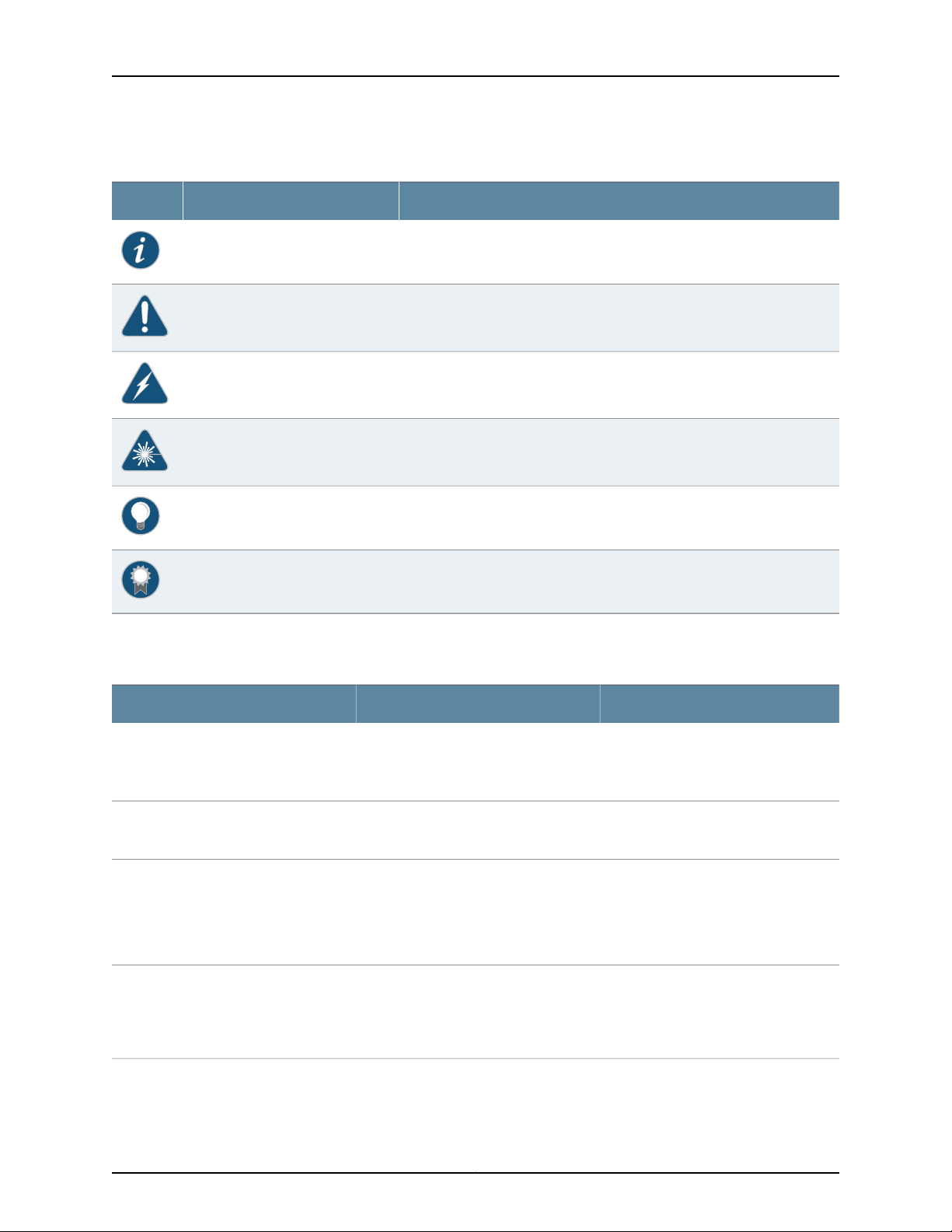
Table 1: Notice Icons
DescriptionMeaningIcon
Indicates important features or instructions.Informational note
Indicates a situation that might result in loss of data or hardware damage.Caution
Alerts you to the risk of personal injury or death.Warning
Alerts you to the risk of personal injury from a laser.Laser warning
Indicates helpful information.Tip
Table 2 on page xxiv defines the text and syntax conventions used in this guide.
Table 2: Text and Syntax Conventions
Represents text that you type.Bold text like this
Fixed-width text like this
Italic text like this
Italic text like this
Represents output that appears on the
terminal screen.
•
Introduces or emphasizes important
new terms.
•
Identifies guide names.
•
Identifies RFC and Internet draft titles.
Represents variables (options for which
you substitute a value) in commands or
configuration statements.
Alerts you to a recommended use or implementation.Best practice
ExamplesDescriptionConvention
To enter configuration mode, type the
configure command:
user@host> configure
user@host> show chassis alarms
No alarms currently active
•
A policy term is a named structure
that defines match conditions and
actions.
•
Junos OS CLI User Guide
•
RFC 1997, BGP Communities Attribute
Configure the machine’s domain name:
[edit]
root@# set system domain-name
domain-name
Copyright © 2015, Juniper Networks, Inc.xxiv
Page 25

Table 2: Text and Syntax Conventions (continued)
Text like this
Represents names of configuration
statements, commands, files, and
directories;configuration hierarchylevels;
or labels on routing platform
components.
About the Documentation
ExamplesDescriptionConvention
•
To configure a stub area, include the
stub statement at the [edit protocols
ospf area area-id] hierarchy level.
•
The console portis labeled CONSOLE.
stub <default-metric metric>;Encloses optional keywords or variables.< > (angle brackets)
| (pipe symbol)
# (pound sign)
[ ] (square brackets)
Indention and braces ( { } )
; (semicolon)
GUI Conventions
Bold text like this
Indicates a choice between the mutually
exclusivekeywords or variables on either
side of the symbol. The set of choices is
often enclosed in parentheses for clarity.
same lineasthe configuration statement
to which it applies.
Encloses a variable for which you can
substitute one or more values.
Identifies a level in the configuration
hierarchy.
Identifies a leaf statement at a
configuration hierarchy level.
Representsgraphicaluser interface(GUI)
items you click or select.
broadcast | multicast
(string1 | string2 | string3)
rsvp { # Required for dynamic MPLS onlyIndicates a comment specified on the
community name members [
community-ids ]
[edit]
routing-options {
static {
route default {
nexthop address;
retain;
}
}
}
•
In the Logical Interfaces box, select
All Interfaces.
•
To cancel the configuration, click
Cancel.
> (bold right angle bracket)
Documentation Feedback
We encourage you to provide feedback, comments, and suggestions so that we can
improve the documentation. You can provide feedback by using either of the following
methods:
•
Online feedback rating system—On any page at the Juniper Networks Technical
Documentation site at http://www.juniper.net/techpubs/index.html, simply click the
stars to rate thecontent, and usethe pop-upform to provide us with information about
your experience. Alternately, you can use the online feedback form at
https://www.juniper.net/cgi-bin/docbugreport/.
Separates levels in a hierarchy of menu
selections.
In the configuration editor hierarchy,
select Protocols>Ospf.
xxvCopyright © 2015, Juniper Networks, Inc.
Page 26

M320 Multiservice Edge Router Hardware Guide
•
E-mail—Sendyourcomments to techpubs-comments@juniper.net.Includethe document
or topic name, URL or page number, and software version (if applicable).
Requesting Technical Support
Technical product support is availablethrough the Juniper Networks Technical Assistance
Center (JTAC). If you are a customer with an active J-Care or JNASC support contract,
or are covered under warranty, and need post-sales technical support, you can access
our tools and resources online or open a case with JTAC.
•
JTAC policies—For a complete understanding of our JTAC procedures and policies,
review the JTAC User Guide located at
http://www.juniper.net/us/en/local/pdf/resource-guides/7100059-en.pdf.
•
Product warranties—For product warranty information, visit
http://www.juniper.net/support/warranty/.
•
JTAC hours of operation—The JTAC centers have resources available 24 hours a day,
7 days a week, 365 days a year.
Self-Help Online Tools and Resources
For quick and easy problem resolution, Juniper Networks has designed an online
self-service portal called the Customer Support Center (CSC) that provides you with the
following features:
•
Find CSC offerings: http://www.juniper.net/customers/support/
•
Search for known bugs: http://www2.juniper.net/kb/
•
Find product documentation: http://www.juniper.net/techpubs/
•
Find solutions and answer questions using our Knowledge Base: http://kb.juniper.net/
•
Download the latest versions of software and review release notes:
http://www.juniper.net/customers/csc/software/
•
Search technical bulletins for relevant hardware and software notifications:
http://kb.juniper.net/InfoCenter/
•
Join and participate in the Juniper Networks Community Forum:
http://www.juniper.net/company/communities/
•
Open a case online in the CSC Case Management tool: http://www.juniper.net/cm/
To verify service entitlement byproductserial number, use ourSerial Number Entitlement
(SNE) Tool: https://tools.juniper.net/SerialNumberEntitlementSearch/
Opening a Case with JTAC
You can open a case with JTAC on the Web or by telephone.
•
Use the Case Management tool in the CSC at http://www.juniper.net/cm/.
•
Call 1-888-314-JTAC (1-888-314-5822 toll-free in the USA, Canada, and Mexico).
Copyright © 2015, Juniper Networks, Inc.xxvi
Page 27

About the Documentation
For international or direct-dial options in countries without toll-free numbers, see
http://www.juniper.net/support/requesting-support.html.
xxviiCopyright © 2015, Juniper Networks, Inc.
Page 28

M320 Multiservice Edge Router Hardware Guide
Copyright © 2015, Juniper Networks, Inc.xxviii
Page 29

PART 1
Overview
•
System Overview on page 3
•
M320 Router Release Notes on page 5
•
Chassis Components and Descriptions on page 7
•
Cooling System Components and Descriptions on page 21
•
Host Subsystem Components and Descriptions on page 23
•
Line Card Components and Descriptions on page 49
•
Power System Components and Descriptions on page 73
•
Switch Fabric Components and Descriptions on page 79
1Copyright © 2015, Juniper Networks, Inc.
Page 30

M320 Multiservice Edge Router Hardware Guide
Copyright © 2015, Juniper Networks, Inc.2
Page 31

CHAPTER 1
System Overview
•
M320 Router Description on page 3
•
M320 Component Redundancy on page 4
M320 Router Description
The M320 Multiservice Edge Router is a high-density edge aggregation, routing, and
service creation platform that builds on Juniper Networks service-built edge design.
Constructed with separations between the control plane, forwarding plane, and services
plane, the router supports multiple services on a single platform. The Junos OS runs on
a control subsystem with dedicated hardware, ensuring that control functions are
performed without affecting theforwardingsubsystem.Forwardingand packet processing
operations in the router are performed by dedicated programmable ASICs that enable
the router to achieve data forwarding rates that match current fiber-optic capacity. This
design eliminates processing and traffic bottlenecks, permitting the router to achieve
high performance.
The router canbe deployed in core,peering, and datacenter applications, but is optimized
for dense edge aggregation and service creation. The M320 router can provide a single
point of edge aggregation for thousands of customers over any access type, including
ATM, Frame Relay, Ethernet, and TDM, at any speed from DS0 up to OC192/STM64 and
10-Gigabit Ethernet.
The router is a half-rack chassis that supports up to eight Flexible PIC Concentrators
(FPCs) providing up to 64 SONET/SDH OC48/STM16, 16 SONET/SDH OC192/STM64,
or 160 Gigabit Ethernet ports for the router. In a standalone configuration, the router's
maximum aggregate throughput is 320 gigabits per second (Gbps), half duplex. The
router supports up to eight of these FPCs:
•
Type 1 FPCs—Rated at 4 Gbps full duplex, supports up to four PICs.
•
Type 2 FPCs—Rated at 16 Gbps full duplex, supports up to four PICs.
•
Type 3 FPCs—Rated at 20 Gbps full duplex, supports up to two PICs, including
higher-speed PICs.
The router can operate with any FPC type in any slot. Type 1 FPCs and Type 2 FPCs each
support four PICs, and Type 3 FPCs supports two PICs.
3Copyright © 2015, Juniper Networks, Inc.
Page 32

M320 Multiservice Edge Router Hardware Guide
Related
Documentation
M320 Chassis Description on page 7•
• M320 Router Physical Specifications on page 86
• M320 Environmental Specifications on page 93
• M320 Power Requirements on page 96
M320 Component Redundancy
A fully configured router is designed so that no single point of failure can cause the entire
system to fail. Only a fully configured router provides complete redundancy. All other
configurations provide partial redundancy. The following major hardware components
are redundant:
•
Switch Interface Boards (SIBs)—A fully configured router has four SIBs. Each FPC has
a dedicated ASICwith fourhigh-speed links that connect tothe SIBs (one link per SIB).
In the event of a complete SIB failure, the traffic is forwarded across the remaining
three planes with a slight degradation in performance. When the failed SIB is replaced,
the router regains full forwarding capacity.
•
Host subsystem—The host subsystem consists of a Routing Engine functioning together
with a CB. To operate, each host subsystem requires a Routing Engine installed in an
adjacent slot to the CB. The router can have one or two host subsystems. If two host
subsystems are installed, one functions as the master and the other functions as the
backup. If the master host subsystem (or either of its components) fails or is taken
offline, the backup can take over as the master.
Related
Documentation
For information about the effect of taking the host subsystem offline, see “Taking the
M320 HostSubsystem Offline” on page213. Formore information about highavailability
features, see the Junos OS High Availability Library for Routing Devices.
•
Powersupplies—A router witha minimum of three AC power supplies or fourDC power
supplies is fully power redundant. In the AC configuration, all power supplies share the
load evenly. In the DC configuration, two power supplies share the load to some of the
components, and two other power supplies share the load to the remaining
components. In both configurations, if one power supply fails, the remaining power
supplies can provide full power to the router.
•
Cooling system—The coolingsystemhas redundant components,which are controlled
by the host subsystem. If one of the fans fails, the host subsystem increases the speed
of the remaining fans to provide sufficient cooling for the router indefinitely.
• M320 SIB Description on page 79
• M320 Host Subsystem Description on page 23
• M320 Cooling System Description on page 21
• M320 Power System Description on page 73
Copyright © 2015, Juniper Networks, Inc.4
Page 33

CHAPTER 2
M320 Router Release Notes
•
Outstanding Issues with the M320 Router on page 5
•
Errata with the M320 Router Documentation on page 5
Outstanding Issues with the M320 Router
This section lists outstanding hardware issues with the M320 Multiservice Edge Router.
For information about software issues, see the Junos OS Release Notes.
•
There are currently no outstanding issues for the M320 router.
Related
Documentation
Errata with the M320 Router Documentation on page 5•
Errata with the M320 Router Documentation
There are currently no outstanding documentation issues for the M320 router.
Related
Documentation
• Outstanding Issues with the M320 Router on page 5
5Copyright © 2015, Juniper Networks, Inc.
Page 34

M320 Multiservice Edge Router Hardware Guide
Copyright © 2015, Juniper Networks, Inc.6
Page 35

CHAPTER 3
Chassis Components and Descriptions
•
M320 Chassis Description on page 7
•
M320 Midplane Description on page 10
•
M320 Fuses on page 12
•
M320 Cable Management System Description on page 12
•
M320 Connector Interface Panel (CIP) Description on page 13
•
M320 Craft Interface Description on page 15
•
M320 Craft Interface Alarm LEDs and ACO/LT Button on page 16
•
M320 Craft Interface LED Display and Navigation Buttons on page 16
•
M320 Craft Interface Host Subsystem LEDs on page 18
•
M320 Craft Interface FPC LEDs and Online/Offline Buttons on page 18
•
M320 Craft Interface Power Supply LEDs on page 19
•
M320 Craft Interface SIB LEDs on page 19
M320 Chassis Description
The router chassis is a rigid sheet metal structure that houses all the other router
components (see Figure 1 on page 8). The chassis measures 34.80 in. (88.4 cm) high,
17.43 in. (44.3 cm) wide, and 25.64 in. (65.1 cm) deep (from the front-mounting flanges
to the rearof thechassis). The chassiscan be installedin many types of racks or cabinets.
For moreinformation,see “M320Cabinet Size and Clearance Requirements” on page88,
and “Rack Requirements for the M320 Router” on page 87.
The chassis includes the following features (see Figure 1 on page 8, Figure 2 on page 9,
and Figure 3 on page 10):
•
One pair of metal adjustable center-mounting brackets that can be attached to one
of 11 positions on the side of the chassis. You can use the brackets for mounting the
chassis in the rack or cabinet.
•
Two installation handles on the top to facilitate positioning the router in the rack. Do
not use the handles to lift the router.
•
Two electrostatic discharge points (banana plug receptacles): one front and one rear.
7Copyright © 2015, Juniper Networks, Inc.
Page 36

M320 Multiservice Edge Router Hardware Guide
Figure 1: Front View of a Fully Configured Router Chassis
CAUTION: Before removing or installing components of a router, attach
an ESD strap to an ESD point and place the other end of the strap around
your bare wrist. Failure to use an ESD strap could result in damage to the
router.
Copyright © 2015, Juniper Networks, Inc.8
Page 37

Chapter 3: Chassis Components and Descriptions
Figure 2: Rear View of a Fully Configured AC-Powered Router Chassis
9Copyright © 2015, Juniper Networks, Inc.
Page 38

M320 Multiservice Edge Router Hardware Guide
Figure 3: Rear View of a Fully Configured DC-Powered Router Chassis
For chassis serial number information , see “Locating M320 Component Serial Numbers
Using the CLI” on page 299.
Related
Documentation
M320 Router Description on page 3•
• Installing the M320 Chassis Using a Mechanical Lift on page 136
• Installing the M320 Chassis in the Rack Manually on page 151
• M320 Installation Safety Guidelines on page 323
• M320 Router Physical Specifications on page 86
M320 Midplane Description
The midplane is located in the center of the chassis and forms the rear of the FPC card
cage (see Figure 4 on page 11). The FPCs install into the midplane from the front of the
Copyright © 2015, Juniper Networks, Inc.10
Page 39

Chapter 3: Chassis Components and Descriptions
chassis, and the SIBs, Routing Engines, and CBs install into the midplane from the rear
of the chassis. The power supplies and cooling system components also connect to the
midplane.
The midplane performs the following major functions:
•
Data path—Data packets are transferred across the midplane from the Packet
Forwarding Engine on the originating FPC to the SIBs, and from the SIBs across the
midplane to the Packet Forwarding Engine on the destination FPC.
•
Power distribution—The router power supplies are connected to the midplane, which
distributes power to all the router components.
•
Signal path—Themidplane provides the signal path to theFPCs, SIBs, RoutingEngines,
CB, and other system components for monitoring and control of the system.
Figure 4: Midplane
For chassis serial number information , see “Locating M320 Component Serial Numbers
Using the CLI” on page 299.
11Copyright © 2015, Juniper Networks, Inc.
Page 40

M320 Multiservice Edge Router Hardware Guide
Related
Documentation
M320 Router Description on page 3•
• M320 Host Subsystem Description on page 23
• M320 Cabinet Size and Clearance Requirements on page 88
M320 Fuses
The router uses fuses from the Cooper Bussman brand GMT series for the CB, SIBs, and
FPCs. The fuses are located in the rear of the midplane behind the power supply in slot
PEM0. When the fuse for a component blows, the component stops functioning even
though it is installed correctly and the power supplies are providing power to the router.
For more information, see “Troubleshooting the M320 Fuses” on page 290. For fuse
replacement instructions, see “Replacing an M320 Fuse” on page 199.
Related
Documentation
M320 Fuse Specifications on page 99•
• Preventing Electrostatic Discharge Damage to an M320 Router on page 318
M320 Cable Management System Description
The cable management system (see Figure 5 on page 12) consists of a row of nine
semicircular plastic bobbinsmounted onthe front of the router below the FPCcard cage.
The PIC cables pass between the bobbins and into thetray, keeping the cables organized
and securely in place. The curvature of the bobbins also helps maintain the proper bend
radius for optical PIC cables.
You can pull the cable management system up and outward to lock it into the
maintenance position. This allows you to access the lower fan tray and the front air filter.
Figure 5: Cable Management System
The router; ships with an accessory box that contains four cable guards—two upper and
two lower—that you can install on the front-mounting flanges of the chassis after you
have mounted the chassis in a rack or cabinet. The cable guards protect the PIC and CIP
cables from rubbing against the front edges of the chassis.
Included with your router shipment is a clear plastic cable cover that you can attach to
slots in the cable guards without using tools. The cable cover prevents the PIC and CIP
cables from being disturbed or snagged.
Copyright © 2015, Juniper Networks, Inc.12
Page 41

Chapter 3: Chassis Components and Descriptions
Related
M320 Chassis Description on page 7•
Documentation
M320 Connector Interface Panel (CIP) Description
The CIP is located at the left side of the FPC card cage. The front electrostatic discharge
point is located near the bottom of the CIP.
•
CIP Components on page 13
•
Routing Engine Ports on page 14
•
Alarm Relay Contacts on page 15
CIP Components
The Connector Interface Panel (CIP) consists of Ethernet, console, and auxiliary
connectors for the Routing Engines and alarm relay contacts (see Figure 6 on page 14).
13Copyright © 2015, Juniper Networks, Inc.
Page 42

M320 Multiservice Edge Router Hardware Guide
Figure 6: CIP
Routing Engine Ports
The CIP has two sets of ports that you use to connect the Routing Engines to external
management devices. From thesemanagementdevices, you can use the CLIto configure
the router.
The upper set of ports, labeled HOST 0, connects to the Routing Engine in slot RE0; and
the lower set,labeledHOST1, connects to the Routing Enginein slot RE1. Each set includes
the following ports:
•
ETHERNET—Connects the Routing Engine through an Ethernet connection to a
management LAN (or any other device that plugs into an Ethernet connection) for
Copyright © 2015, Juniper Networks, Inc.14
Page 43

Alarm Relay Contacts
Chapter 3: Chassis Components and Descriptions
out-of-band management. The port uses an autosensing RJ-45 connector to support
both 10- and 100-Mbps connections. Two small LEDs on the right edge of the port
indicate the connection in use: the LED labeled ETHERNET lights yellow or green for a
10-Mbps or 100-Mbps connection, and the LED labeled ACT lights green when traffic
is passing through the port.
•
CONSOLE—Connects the Routing Engine to a system console through an RS-232
(EIA-232) serial cable.
•
AUX— Connects the Routing Engine to a laptop, modem, or other auxiliary device
through an RS-232 (EIA-232) serial cable.
The CIPhas two alarm relay contacts forconnecting the router to external alarm devices.
Whenever a system conditiontriggers either thered or yellow alarmon the craftinterface,
the alarm relay contacts are also activated. The alarm relay contacts are located below
the Routing Engine ports. The terminal blocks that plug into the alarm relay contacts are
supplied with the router. They accept wire of any gauge between 28-AWG and 14-AWG
(0.08 and 2.08 mm2), which is not provided. Use the gauge of wire appropriate for the
external device you are connecting.
Related
Documentation
M320 Craft Interface Description on page 15•
• Replacing the M320 CIP on page 189
M320 Craft Interface Description
The craft interface allows you to view status and troubleshooting information at a glance
and to perform many system control functions. It is hot-insertable and hot-removable.
The craft interface is located onthe front of the routerabovethe FPCs.Figure 7 onpage 15
shows the front panel of the M320 craft interface.
Figure 7: Front Panel of the Craft Interface
Related
Documentation
• M320 Craft Interface Alarm LEDs and ACO/LT Button on page 16
• M320 Craft Interface Host Subsystem LEDs on page 18
• Replacing an M320 Craft Interface on page 197
15Copyright © 2015, Juniper Networks, Inc.
Page 44

M320 Multiservice Edge Router Hardware Guide
M320 Craft Interface Alarm LEDs and ACO/LT Button
Two large alarm LEDs are located at the upper left of the craft interface . The circular
red LED lights to indicate a critical condition that can result in a system shutdown. The
triangular yellow LED lights to indicate a less severe condition that requires monitoring
or maintenance. Both LEDs can be lit simultaneously.
A condition that causes an LED to light also activates the corresponding alarm relay
contact on the connector interface panel (CIP). The LCD on the craft interface reports
the cause of the alarm.
To deactivate red and yellow alarms, press the button labeled ACO/LT (for “alarm
cutoff/lamp test”), which is located to the right of the alarm LEDs. Deactivating an alarm
turns off both LEDs and deactivates the device attached to the corresponding alarm
relay contact on the CIP. However, the LCD continues to report the alarm message until
you clear the condition that caused the alarm.
Table 3 on page 16 describes the alarm LEDs and alarm cutoff button in more detail.
Table 3: Alarm LEDs and Alarm Cutoff/Lamp Test Button
DescriptionStateColorShape
Critical alarm LED—Indicates a criticalcondition that
can cause the router to stop functioning. Possible
causes include component removal, failure, or
overheating.
WarningalarmLED—Indicatesa serious butnonfatal
error condition, such as a maintenance alert or a
significant increase in component temperature.
Alarm cutoff/lamptestbutton—Deactivates red and
yellowalarms. Causes allLEDs onthe craft interface
to light (for testing purposes), when pressed and
held.
Related
Documentation
On steadilyRed
On steadilyYellow
——
M320 Craft Interface Description on page 15•
• M320 Connector Interface Panel (CIP) Description on page 13
• M320 Craft Interface LED Display and Navigation Buttons on page 16
M320 Craft Interface LED Display and Navigation Buttons
A four-line LED display is located in the craft interface, along with six navigation buttons.
The LED display operates in two modes:
•
LED display idle mode
•
LED display alarm mode
Copyright © 2015, Juniper Networks, Inc.16
Page 45

Chapter 3: Chassis Components and Descriptions
During normaloperation, the LEDdisplay operatesin idle mode and reports current status
information, as shown in Figure 8 on page 17.
Figure 8: LED Display in Idle Mode
The lines in the display report the following information:
•
First line—Router name.
•
Second line—Length of time the router has been running, reported in the following
form:
Up days + hours:minutes
•
Third and fourth lines—Status messages, which rotate at 2-second intervals. Some
conditions, such as removal or insertion of a system component, can interrupt the
messages.
To add a message that alternates every 2 seconds with the default status messages,
use thesetchassis displaymessage command. For moreinformation,see the CLIExplorer.
When a red or yellow alarm occurs, the LED display switches to alarm mode and reports
about the alarm condition, as shown in Figure 9 on page 17.
Figure 9: LED Display in Alarm Mode
The lines in the display report the following information:
•
First line—Router name.
•
Second line—Number of active alarms.
•
Third and fourth lines—Individual alarm messages, with the most severe condition
shown first. The prefix oneach line indicates whether the alarmis ared (R) or yellow (Y)
alarm.
For a list of alarm messages that can appear on the LED display, see “M320 Chassis and
Interface Alarm Messages” on page 285.
17Copyright © 2015, Juniper Networks, Inc.
Page 46

M320 Multiservice Edge Router Hardware Guide
Related
Documentation
M320 Craft Interface Description on page 15•
• M320 Craft Interface Alarm LEDs and ACO/LT Button on page 16
M320 Craft Interface Host Subsystem LEDs
Each host subsystem has three LEDs, located in the middle of the craft interface, that
indicate its status. The LEDs labeled RE0 show the status of the Routing Engine in slot
RE0 and the CB in slot CB0. The LEDs labeled RE1 show the status of the Routing Engine
in slot RE1 and the CB in slot CB1. Table 4 on page 18 describes the functions of the host
subsystem LEDs.
Table 4: M320 Host Subsystem LEDs
Related
Documentation
M320 Host Subsystem Description on page 23•
• M320 Craft Interface Description on page 15
DescriptionStateColorLabel
Host is offline.On steadilyRedFAIL
Host is online and is functioning normally.On steadilyGreenOK
Host is functioning as the master.On steadilyGreenMASTER
• M320 Craft Interface Alarm LEDs and ACO/LT Button on page 16
M320 Craft Interface FPC LEDs and Online/Offline Buttons
Each FPC slot has two LEDs that indicate its status. The FPC LEDs, labeled FPC0 through
FPC7, are located along the bottom of the craft interface. Table 5 on page 18 describes
the functions of the FPC LEDs.
Table 5: FPC LEDs
DescriptionStateColorLabel
FPC has failed.On steadilyRedFAIL
FPC is functioning normally.On steadilyGreenOK
FPC is starting up.Blinking
Related
Documentation
M320 Flexible PIC Concentrator (FPC) Description on page 49•
• M320 Craft Interface Description on page 15
• M320 Connector Interface Panel (CIP) Description on page 13
• Troubleshooting the M320 FPCs on page 289
Copyright © 2015, Juniper Networks, Inc.18
Page 47

M320 Craft Interface Power Supply LEDs
Each power supply has two LEDs on the craft interface that indicate its status. The LEDs,
labeled 0 through 3, are located in the middle of the craft interface under the POWER
label. Table 6 on page 19 describes the functions of the power supply LEDs.
Table 6: Power Supply LEDs on the Craft Interface
Chapter 3: Chassis Components and Descriptions
DescriptionStateColorLabel
Power supply has failed.On steadilyRedFAIL
Power supply is functioning normally.On steadilyGreenOK
Related
Documentation
M320 Craft Interface Description on page 15•
• M320 AC Power Supplies Description on page 73
• M320 DC Power Supplies Description on page 74
M320 Craft Interface SIB LEDs
Each SIBhas two LEDson thecraftinterfacethat indicate its status. The SIB LEDs, labeled
SIB0 through SIB2, are located on the upper right of the craft interface. The ACTIVE LED
on the SIB faceplate is not replicated on the craft interface. Table 7 on page 19 describes
the functions of the SIB LEDs.
Table 7: SIB LEDs on the Craft Interface
Related
Documentation
• M320 SIB Description on page 79
• M320 SIB LEDs on page 81
DescriptionStateColorLabel
SIB has failed.On steadilyRedFAIL
SIB is functioning normally.On steadilyGreenOK
• M320 Craft Interface Description on page 15
• Maintaining the M320 SIBs on page 279
19Copyright © 2015, Juniper Networks, Inc.
Page 48

M320 Multiservice Edge Router Hardware Guide
Copyright © 2015, Juniper Networks, Inc.20
Page 49

CHAPTER 4
Cooling System Components and
Descriptions
•
M320 Cooling System Description on page 21
M320 Cooling System Description
The cooling system consists of the following components:
•
Two front fan trays
•
Front air filter
•
Rear fan tray
•
Rear air filter
The cooling system components work together to keep all router components within the
acceptable temperature range (see Figure 10 on page 21). All fan trays and filters are
hot-insertable and hot-removable. The two front fan trays are interchangeable. The front
and rear fan trays are not interchangeable.
Figure 10: Airflow Through the Chassis
21Copyright © 2015, Juniper Networks, Inc.
Page 50

M320 Multiservice Edge Router Hardware Guide
The host subsystem monitors the temperature of the router components. When the
router is operating normally, the fans function at lower than full speed. If a fan fails or
the ambient temperature rises above a threshold, the speed of the remaining fans is
automatically adjusted to keep the temperature within the acceptable range. If the
ambient maximum temperature specification is exceeded and the system cannot be
adequately cooled, the Routing Engine shuts down some or all of the hardware
components.
Related
Documentation
• M320 Cabinet Airflow Requirements on page 90
• Maintaining the M320 Fan Trays on page 268
• Troubleshooting the M320 Cooling System on page 287
Copyright © 2015, Juniper Networks, Inc.22
Page 51

CHAPTER 5
Host Subsystem Components and
Descriptions
•
M320 Host Subsystem Description on page 23
•
M320 Routing Engine Description on page 24
•
M320 Routing Engine 600 Description on page 25
•
M320 Routing Engine 1600 Description on page 26
•
M320 Routing Engine 2000 Description on page 27
•
M320 RE-A-1800 Routing Engine Description on page 28
•
RE-A-1800 Routing Engine LEDs on page 31
•
Routing Engine Specifications on page 31
•
Supported Routing Engines by Router on page 34
•
M320 Control Board (CB) Description on page 45
•
M320 Control Board (CB) LEDs on page 46
M320 Host Subsystem Description
The host subsystem provides the routing and system management functions of the
router. You can install one or two host subsystems on the router. To operate, each host
subsystem functions as a unit; the Routing Engine requires the corresponding Control
Board (CB) and vice versa.
NOTE: We recommend that you install two host subsystems for redundant
protection. If you install only one host subsystem, we recommend that you
install it in slot RE0.
NOTE: Each host subsystem has three LEDs that display its status. The LEDs
that report host module status (including Routing Engine status) are located
in the middle of the craft interface rather than the Routing Engine faceplate.
For more information about the host subsystem LEDs, see “M320 Craft
Interface Host Subsystem LEDs” on page 18.
23Copyright © 2015, Juniper Networks, Inc.
Page 52

M320 Multiservice Edge Router Hardware Guide
NOTE: For specific information about Routing Engine components (for
example, the amount of DRAM), issue the show chassis routing-engine
command.
NOTE: If two Routing Engines are installed, they must both be the same
hardware model.
Related
Documentation
Maintaining the M320 Host Subsystem on page 269•
• Taking the M320 Host Subsystem Offline on page 213
M320 Routing Engine Description
The Routing Engine runs the Junos operating system (OS). The software processes that
run on the Routing Engine maintain the routing tables, manage the routing protocols
used on the router, control the router interfaces, control some chassis components, and
provide the interface for system management and user access to the router.
You can install one or two Routing Engines in the router. The Routing Engines install into
the upperrear of the chassis inthe slots labeled RE0 and RE1. Each Routing Engine requires
a CB to be installed in the adjacent slot. RE0 installs below CB0, and RE1 installs above
CB1. A Routing Engine does not power up if a CB is not present in the adjacent slot.
If two Routing Engines are installed, one functions as the master, and the other acts as
the backup. If themaster Routing Enginefails or is removed, and the backup is configured
appropriately, the backup can take over as the master. If the Routing Engines are
configured for nonstop active routing, the backup Routing Engine automatically
synchronizes its configuration and state with the master Routing Engine. Any update to
the master Routing Engine state is replicated onthe backup RoutingEngine. If the backup
Routing Engine assumes mastership, packet forwarding continues through the router
without interruption. For more information about nonstop active routing, see the Junos
OS High Availability Library for Routing Devices.
The master Routing Engine (if nonstop active routing is configured) and the backup
Routing Engine are hot-removable and hot-insertable. A nonredundant Routing Engine
or master Routing Engine (if nonstop active routing is not configured) is hot-pluggable.
The M320 router supports the following Routing Engines:
•
RE-600-2048
•
RE-1600-2048
•
RE-A-2000-4096
•
RE-A-1800x2 for Junos OS Release 10.4.
Copyright © 2015, Juniper Networks, Inc.24
Page 53

Chapter 5: Host Subsystem Components and Descriptions
Related
Documentation
M320 Connector Interface Panel (CIP) Description on page 13•
• Replacing an M320 Routing Engine on page 216
• M320 Routing Engine 600 Description on page 25
• M320 Routing Engine 1600 Description on page 26
• M320 Routing Engine 2000 Description on page 27
• M320 RE-A-1800 Routing Engine Description on page 28
M320 Routing Engine 600 Description
Each M320 Routing Engine 600 consists of the following components:
•
CPU—Runs Junos OS to maintain the router's routing tables and routing protocols. It
has a Pentium-class processor.
•
DRAM—Provides storage for the routing and forwarding tables and for other Routing
Engine processes.
•
CompactFlash card—Provides primarystorage forsoftware images, configuration files,
and microcode. The CompactFlash card is inaccessible from outside the router.
•
Hard disk—Provides secondary storage for log files, memory dumps, and rebooting the
system if the CompactFlash card fails.
•
One PC card slot—Accepts a removable PC card, which stores software images for
system upgrades.
•
LED—Indicatesdisk activity forthe internalIDE interface. It does not necessarily indicate
routing-related activity.
•
Interfaces for out-of-band management access—Provide information about
Routing Engine status to devices (console, laptop, or terminal server) that can be
attached to access ports located on the Connector Interface Panel (CIP).
Each Routing Engine has one 10/100-Mbps Ethernet port for connecting to a
management network, and two asynchronous serial ports—one for connecting to a
console and one for connecting to a modem or other auxiliary device.
•
EEPROM—Stores the serial number of the Routing Engine.
•
Reset button—Reboots the Routing Engine when pressed.
On the RE-600-2048 Routing Engine, the boot sequence for the storage media is as
follows: the PC card (if present), then the CompactFlash card (if present), then the hard
disk.
The device from which the router boots is called the primary boot device, and the other
device is the alternate boot device.
NOTE: If the router boots from an alternatebootdevice,a yellowalarmlights
the LED on the router’s craft interface.
25Copyright © 2015, Juniper Networks, Inc.
Page 54

M320 Multiservice Edge Router Hardware Guide
Related
Documentation
M320 Connector Interface Panel (CIP) Description on page 13•
• M320 Routing Engine Description on page 24
• Replacing an M320 Routing Engine on page 216
M320 Routing Engine 1600 Description
Figure 11: Routing Engine 1600
Each Routing Engine(shown inFigure11 onpage26) consists of the following components:
•
CPU—Runs Junos OS to maintain the router's routing tables and routing protocols. It
has a Pentium-class processor.
•
DRAM—Provides storage for the routing and forwarding tables and for other Routing
Engine processes.
•
CompactFlash card—Provides primarystorage forsoftware images, configuration files,
and microcode. The CompactFlash card is inaccessible from outside the router.
•
Hard disk—Provides secondary storage for log files, memory dumps, and rebooting the
system if the CompactFlash card fails.
•
PC card slots—Accept removable PC cards, which store software images for system
upgrades.
•
LED—Indicatesdisk activity forthe internalIDE interface. It does not necessarily indicate
routing-related activity.
•
Interfaces for out-of-band management access—Provide information about
Routing Engine status to devices (console, laptop, or terminal server) that can be
attached to access ports located on the Connector Interface Panel (CIP).
Each Routing Engine has one 10/100-Mbps Ethernet port for connecting to a
management network, and two asynchronous serial ports—one for connecting to a
console and one for connecting to a modem or other auxiliary device.
•
EEPROM—Stores the serial number of the Routing Engine.
•
Reset button—Reboots the Routing Engine when pressed.
Copyright © 2015, Juniper Networks, Inc.26
Page 55

Chapter 5: Host Subsystem Components and Descriptions
On the RE-1600-2048 Routing Engine, the boot sequence for the storage media is as
follows: the PC card in SLOT 0 (if present), then the PC card in SLOT 1 (if present), then
the CompactFlash card (if present), then the hard disk.
The device from which the router boots is called the primary boot device, and the other
device is the alternate boot device.
NOTE: If the router boots from an alternatebootdevice,a yellowalarmlights
the LED on the router’s craft interface.
Related
Documentation
M320 Connector Interface Panel (CIP) Description on page 13•
• M320 Routing Engine Description on page 24
• Replacing an M320 Routing Engine on page 216
M320 Routing Engine 2000 Description
Each Routing Engine (shown in Figure 12 on page 28) consists of the following
components:
•
CPU—Runs Junos OS to maintain the router's routing tables and routing protocols. It
has a Pentium-class processor.
•
DRAM—Provides storage for the routing and forwarding tables and for other Routing
Engine processes.
•
CompactFlash card—Provides primarystorage forsoftware images, configuration files,
and microcode. The CompactFlash card is inaccessible from outside the router.
•
Hard disk—Provides secondary storage for log files, memory dumps, and rebooting the
system if the CompactFlash card fails.
•
USB port—Provides a removable media interface through which you can install the
Junos OS manually. The Junos OS supports USB version 1.0.
•
LED—Indicatesdisk activity forthe internalIDE interface. It does not necessarily indicate
routing-related activity.
•
Interfaces for out-of-band management access—Provide information about
Routing Engine status to devices (console, laptop, or terminal server) that can be
attached to access ports located on the Connector Interface Panel (CIP).
Each Routing Engine has one 10/100-Mbps Ethernet port for connecting to a
management network, and two asynchronous serial ports—one for connecting to a
console and one for connecting to a modem or other auxiliary device.
•
EEPROM—Stores the serial number of the Routing Engine.
•
Reset button—Reboots the Routing Engine when pressed.
27Copyright © 2015, Juniper Networks, Inc.
Page 56

M320 Multiservice Edge Router Hardware Guide
Figure 12: Routing Engine 2000
On the RE-A-2000-4096 Routing Engine, the boot sequence for the storage media is as
follows: USB device (if present), then the CompactFlash card (if present), then the hard
disk.
The device from which the router boots is called the primary boot device, and the other
device is the alternate boot device.
NOTE: If the router boots from an alternatebootdevice,a yellowalarmlights
the LED on the router’s craft interface.
Related
Documentation
M320 Connector Interface Panel (CIP) Description on page 13•
• M320 Routing Engine Description on page 24
• Replacing an M320 Routing Engine on page 216
M320 RE-A-1800 Routing Engine Description
•
Routing Engine Components on page 28
•
Routing Engine Boot Sequence on page 30
Routing Engine Components
Each Routing Engine (shown in Figure 13 on page 29 and Figure 14 on page 29) consists
of the following components:
•
CPU—Runs Junos OS to maintain the router's routing tables and routing protocols.
•
DRAM—Provides storage for the routing and forwarding tables and for other Routing
Engine processes.
•
USB port—Provides a removable media interface through which you can install the
Junos OS manually. See Figure 15 on page 30. Junos supports USB version 1.0.
•
CompactFlash card—Provides primarystorage forsoftware images, configuration files,
and microcode. The disk is a fixed compact flash and is inaccessible from outside the
router.
Copyright © 2015, Juniper Networks, Inc.28
Page 57

g006041
USB
port
Reset
button
Online
LED
Storage
LED
SSD
slot 2
SSD
slot 1
Online/Offline
button
Extractor
clip
Extractor
clip
g006038
Extractor clip
Extractor clip
USB port
Reset
button
SSD
slot 2
SSD
slot 1
Online/Offline
button
Chapter 5: Host Subsystem Components and Descriptions
•
SSD—Provides storage for log files, memory dumps, and rebooting the system if the
CompactFlash card fails.
•
LED—Indicates disk activity. It does not necessarily indicate routing-related activity.
NOTE: The LEDs that report host module status (including Routing Engine
status) are on the craft interface rather than the Routing Engine faceplate.
•
Storage LED—Indicates disk activity for the solid state disk drive.
•
Interfaces for out-of-band management access—Provide information about
Routing Engine status to devices (console, laptop, or terminal server) that can be
attached to access ports located on the craft interface.
Each Routing Engine has one 10/100-Mbps Ethernet port for connecting to a
management network, and two asynchronous serial ports—one for connecting to a
console and one for connecting to a modem or other auxiliary device.
•
EEPROM—Stores the serial number of the Routing Engine.
•
Reset button—Reboots the Routing Engine when pressed.
•
Offline button—Takes the Routing Engine offline when pressed.
•
Extractor clips—Control the locking system that secures the Routing Engine.
Figure 13: RE-A-1800 Routing Engine
Figure 14: RE-A-1800x2 Routing Engine
29Copyright © 2015, Juniper Networks, Inc.
Page 58

M320 Multiservice Edge Router Hardware Guide
NOTE: For specific information about Routing Engine components (for
example, the amount of DRAM), issue the show chassis routing-engine
command.
Figure 15: USB Memory Device in an Routing Engine
Routing Engine Boot Sequence
The Routing Engine boots from the storage media in this order: the USB device, then the
CompactFlash card (if present), then the two solid state drives (SSD) and then the LAN.
The device from which the router boots is called the primary boot device, and the other
device is the alternate boot device.
Related
Documentation
• M320 Routing Engine Description on page 24
• M320 Host Subsystem Description on page 23
• RE-A-1800 Routing Engine LEDs on page 31
• Maintaining the M320 Host Subsystem on page 269
• Taking the M320 Host Subsystem Offline on page 213
NOTE: If the router boots from an alternatebootdevice,a yellowalarmlights
the LED on the router’s craft interface.
Copyright © 2015, Juniper Networks, Inc.30
Page 59

RE-A-1800 Routing Engine LEDs
Each Routing Engine has four LEDs that indicate its status. The LEDs, labeled MASTER,
STORAGE, ONLINE, and OK/FAIL, are located directly on the faceplate of the Routing
Engine. Table 8 on page 31 describes the functions of the Routing Engine LEDs.
Table 8: Routing Engine LEDs
Chapter 5: Host Subsystem Components and Descriptions
DescriptionStateColorLabel
Routing Engine is the Master.On steadilyBlueMASTER
Indicates activity on the SSD or Compact Flash.BlinkingGreenSTORAGE
Routing Engine is transitioning online.BlinkingGreenONLINE
Routing Engine is functioning normally.On steadily
Routing Engine has failed.On steadilyRedOK/FAIL
Related
Documentation
M320 LED Overview on page 284•
• M320 RE-A-1800 Routing Engine Description on page 28
• Maintaining the M320 Host Subsystem on page 269
Routing Engine Specifications
Table 9 on page 31 lists the current specifications for Routing Engines supported on M
Series, MX Series, and T Series routers. Table 10 on page 33 lists the specifications for
end-of-life Routing Engines.
NOTE: For information about PTX Series Routing Engine specifications, see
Routing Engines Supported on PTX Series Routers
Table 9: Routing Engine Specifications
Routing
Engine
RE-400-768
Celeron
Connection
to PFEsMemoryProcessor
Fast Ethernet768 MB400-MHz
40 GB Hard
disk
First Junos OS
SupportMediaDisk
9.01 GB
CompactFlash
card
RE-A-1000-2048
Pentium
2048 MB1.0-GHz
Gigabit
Ethernet
40 GB Hard
disk
CompactFlash
card
8.11 GB
31Copyright © 2015, Juniper Networks, Inc.
Page 60

M320 Multiservice Edge Router Hardware Guide
Table 9: Routing Engine Specifications (continued)
Routing
Engine
RE-A-2000-4096
RE-S-1300-2048
RE-S-2000-4096
Pentium
Pentium
Pentium
Connection
to PFEsMemoryProcessor
4096 MB2.0-GHz
2048 MB1.3-GHz
4096 MB2.0-GHz
8 GB1.8-GHzRE-C1800
16 GB2.6-GHzRE-C2600
8 GB or 16 GB1800-MHzRE-A-1800x2
Gigabit
Ethernet
Gigabit
Ethernet
Gigabit
Ethernet
Ethernet
Ethernet
Ethernet
40 GB Hard
disk
40 GB Hard
disk
40 GB Hard
disk
SSDGigabit
SSDGigabit
32 GB SSDGigabit
CompactFlash
card
CompactFlash
card
CompactFlash
card
4 GB
CompactFlash
card
4 GB
CompactFlash
card
CompactFlash
card
First Junos OS
SupportMediaDisk
8.11 GB
8.21 GB
8.21 GB
T1600 router in a
routing matrix: 9.6R2
StandaloneT640 or
T1600 router:11.2
TX Matrix Plus
router: 9.6R2
10.44 GB
8 GB or 16 GB1800-MHzRE-S-1800x2
Ethernet
8GB or 16 GB1800-MHzRE-S-1800x4
Ethernet
4 GB1.8-GHzRE-S-MX104
Ethernet
4 GB1.73-GHzRE-B-1800x1-4G
Ethernet
16 GB1800-GHzRE-MX2000-1800x4
Ethernet
32 GB1800 GhzRE-S-1800X4-32G-S
Ethernet
32 GB SSDGigabit
CompactFlash
card
32 GB SSDGigabit
CompactFlash
card
–Gigabit
Flash
64 GB SSDGigabit
–Gigabit
32 GB SSDGigabit
4 GB
CompactFlash
card
Internal
CompactFlash
card
4 GB Fixed
Internal
CompactFlash
card
10.44 GB
10.44 GB
13.28 GB NAND
12.1R2, 11.4R4, and
12.2R1
12.3R24 GB Fixed
•
12.3R4
•
13.2R1
Copyright © 2015, Juniper Networks, Inc.32
Page 61

Table 9: Routing Engine Specifications (continued)
Chapter 5: Host Subsystem Components and Descriptions
Routing
Engine
32 GB1800 GhzREMX2K-1800-32G-S
Connection
to PFEsMemoryProcessor
Ethernet
Table 10: End-of-Life Routing Engine Specifications
Routing
Engine
RE-333-256
RE-333-768
RE-600-512
RE-600-2048
256 MB333-MHz
Pentium II
768 MB333-MHz
Pentium II
512 MB600-MHz
Pentium III
2048 MB600-MHz
Pentium III
Connection
to PFEsMemoryProcessor
Fast
Ethernet
Fast
Ethernet
Fast
Ethernet
Fast
Ethernet
6.4 GB
Hard disk
6.4 GB
Hard disk
30 GBHard
disk
40 GBHard
disk
–Gigabit
CompactFlash
card
CompactFlash
card
CompactFlash
card
CompactFlash
card
4 GB Fixed
Internal
CompactFlash
card
First Junos OS
SupportMediaDisk
3.480 MB
3.480 MB
5.4256 MB
5.31 GB
First Junos OS
SupportMediaDisk
•
12.3R4
•
13.2R1
EOL Details
PSN-2003-01-063
PSN-2003-01-063
PSN-2004-07-019
PSN-2008-02-018
RE-850-1536
RE-M40
RE-M40-333-768
RE-M40-600-2048
RE-1600-2048
Pentium III
Pentium
Pentium II
Pentium III
Pentium M
1536 MB850-MHz
256 MB200-MHz
768 MB333-MHz
2048 MB600-MHz
2048 MB1.6-GHz
Fast
Ethernet
Fast
Ethernet
Fast
Ethernet
Fast
Ethernet
Gigabit
Ethernet
40 GBHard
disk
6.4 GB
Hard disk
10 GB Hard
disk
30 GBHard
disk
40 GBHard
disk
CompactFlash
card
CompactFlash
card
CompactFlash
card
CompactFlash
card
CompactFlash
card
7.21 GB
3.280 MB
4.280 MB
5.4128 MB
6.21 GB
PSN-2011-04-226
FA-HW-0101-001
PSN-2003-01-063
PSN-2004-11-020
PSN-2008-02-019
33Copyright © 2015, Juniper Networks, Inc.
Page 62

M320 Multiservice Edge Router Hardware Guide
NOTE: The memory in Table 9 on page 31 indicates the amount of total
memory. To determine the amount of available memory, issue the show
chassis routing-engine CLI command.
On routing platforms that accept two Routing Engines, you cannot mix Routing Engine
types except for a brief period (one minute or so) during an upgrade or downgrade to
two Routing Engines of the same type.
Related
Supported Routing Engines by Router on page 34•
Documentation
Supported Routing Engines by Router
The following tables list the Routing Enginesthat each router supports, the firstsupported
release for the Routing Engine inthe specified router, themanagement Ethernet interface,
and the internal Ethernet interfaces for each Routing Engine.
•
M7i Routing Engines on page 34
•
M10i Routing Engines on page 35
•
M40e Routing Engines on page 35
•
M120 Routing Engines on page 36
•
M320 Routing Engines on page 36
•
MX104 Routing Engines on page 37
•
MX240 Routing Engines on page 37
•
MX480 Routing Engines on page 38
•
MX960 Routing Engines on page 39
•
MX2010 Routing Engines on page 39
•
MX2020 Routing Engines on page 40
•
PTX3000 Routing Engines on page 40
•
PTX5000 Routing Engines on page 40
•
T320 Routing Engines on page 41
•
T640 Routing Engines on page 41
•
T1600 Routing Engines on page 42
•
T4000 Routing Engines on page 43
•
TX Matrix Routing Engines on page 44
•
TX Matrix Plus Routing Engines on page 44
•
TX Matrix Plus (with 3D SIBs) Routing Engines on page 44
M7i Routing Engines
Table 11 on page 35 lists the Routing Engines supported by the M7i router. The M7I router
supports 32-bit Junos OS only.
Copyright © 2015, Juniper Networks, Inc.34
Page 63

Table 11: M7i Routing Engines
Chapter 5: Host Subsystem Components and Descriptions
Name in CLI
OutputModel Number
TSB16445)
RE-B-1800x1RE-B-1800X1-4G
M10i Routing Engines
Table 12 on page 35 lists the Routing Engines supported by the M10i router. The M10I
router supports 32-bit Junos OS only.
Table 12: M10I Routing Engines
Name in CLI
OutputModel Number
TSB16445)
First Supported 32-bit Junos
OS Release
12.1R2
First Supported 32-bit
Junos OS Release
Management
Ethernet
Interface
Management
Ethernet
Interface
fxp09.0RE-5.0RE-400-768 (EOL details:
Internal
Ethernet
Interface
fxp1fxp09.0RE-5.0RE-400-768 (EOL details:
fxp1fxp07.2RE-850RE-850-1536
em0fxp011.4R4
Internal Ethernet
Interface
fxp1
fxp2
RE-B-1800x1RE-B-1800X1-4G
M40e Routing Engines
Table 13 on page 35 lists the Routing Engines supported by the M40e router.
Table 13: M40e Routing Engines
Name in CLI
OutputModel Number
RE-600-2048 (EOL details:
PSN-2008-02-018)
(RE-600)
12.1R2
First Supported Junos OS
Release
fxp07.2RE-850RE-850-1536
Management
Ethernet
Interface
fxp05.3RE-3.0 or RE-3.0
fxp08.1RE-A-1000RE-A-1000-2048
fxp1
fxp2
em0fxp011.4R4
Internal
Ethernet
Interface
fxp1
fxp2
fxp1
fxp2
35Copyright © 2015, Juniper Networks, Inc.
Page 64

M320 Multiservice Edge Router Hardware Guide
M120 Routing Engines
Table 14 on page 36 lists the Routing Engines supported by the M120 router.
Table 14: M120 Routing Engines
Name in CLI
OutputModel Number
First Supported
32-bit Junos OS
Release
First
Supported
64-bit Junos
OS Release
Management
Ethernet
Interface
Internal
Ethernet
Interface
RE-A-1800x2RE-A-1800x2-8G
RE-A-1800x2RE-A-1800x2-16G
RE-A-1800x4RE-A-1800x4-16G
M320 Routing Engines
Table 15 on page 36 lists the Routing Engines supported by the M320 router.
Table 15: M320 Routing Engines
Name in CLI
OutputModel Number
•
11.4R5
•
12.1R3
•
11.4R5
•
12.1R3
•
11.4R5
•
12.1R3
First Supported
32-bit Junos OS
Release
First Supported
64-bit Junos OS
Release
fxp0–8.0R2RE-A-1000RE-A-1000-2048
fxp0–8.0R2RE-A-2000RE-A-2000-4096
fxp010.4
fxp010.4
fxp010.4
Management
Ethernet Interface
fxp1
fxp2
em0
bcm0
fxp1
fxp2
fxp1
fxp2
em0
em1
Internal
Ethernet
Interface
details:
PSN-2008-02-019)
fxp0–6.2RE-4.0RE-1600-2048 (EOL
fxp0–8.1RE-A-2000RE-A-2000-4096
•
•
11.4R5
12.1R3
RE-A-1800x2RE-A-1800x2-8G
fxp010.4
Copyright © 2015, Juniper Networks, Inc.36
fxp1
fxp2
em0
bcm0
em0
bcm0
Page 65

Table 15: M320 Routing Engines (continued)
Chapter 5: Host Subsystem Components and Descriptions
Name in CLI
OutputModel Number
RE-A-1800x2RE-A-1800x2-16G
RE-A-1800X4RE-A-1800x4-8G
MX104 Routing Engines
Table 16 on page 37 lists the Routing Engines supported by MX104 routers.
Table 16: MX104 Routing Engines
Name in CLI
OutputModel Number
First Supported
32-bit Junos OS
Release
•
11.4R5
•
12.1R3
•
11.4R5
•
12.1R3
•
12.2
First Supported
32-bit Junos OS
Release
First Supported
64-bit Junos OS
Release
First Supported
64-bit Junos OS
Release
Management
Ethernet Interface
fxp010.4
fxp010.4
Management
Ethernet
Interface
fxp0–13.2RoutingEngineRE-S-MX104
Internal
Ethernet
Interface
em0
bcm0
em0
em1
Internal Ethernet
Interface
fxp1
fxp2
MX240 Routing Engines
Table 17 on page 37 lists the Routing Engines supported by MX240 routers.
Table 17: MX240 Routing Engines
Name in CLI
OutputModel Number
RE-S-1800x2RE-S-1800x2-8G
RE-S-1800X2RE-S-1800x2-16G
First Supported
32-bit Junos OS
Release
•
11.4R5
•
12.1R3
•
11.4R5
•
12.1R3
First Supported
64-bit Junos OS
Release
Management
Ethernet
Interface
fxp0–9.0RE-S-1300RE-S-1300-2048
fxp0–9.0RE-S-2000RE-S-2000-4096
fxp010.4
fxp010.4
Internal Ethernet
Interface
fxp1
fxp2
fxp1
fxp2
em0
em1
em0
em1
37Copyright © 2015, Juniper Networks, Inc.
Page 66

M320 Multiservice Edge Router Hardware Guide
Table 17: MX240 Routing Engines (continued)
Name in CLI
OutputModel Number
RE-S-1800X4RE-S-1800x4-8G
RE-S-1800x4RE-S-1800x4-16G
RE-S-1800X4RE-S-1800X4-32G-S
MX480 Routing Engines
Table 18 on page 38 lists the Routing Engines supported by MX480 routers.
Table 18: MX480 Routing Engines
Name in CLI
OutputModel Number
First Supported
32-bit Junos OS
Release
•
11.4R5
•
12.1R3
•
11.4R5
•
12.1R3
•
12.3R4
•
13.2R1
First Supported
32-bit Junos OS
Release
First Supported
64-bit Junos OS
Release
•
12.3R4
•
13.2R1
First Supported
64-bit Junos OS
Release
Management
Ethernet
Interface
fxp010.4
fxp010.4
fxp0
Management
Ethernet
Interface
fxp0–8.4RE-S-1300RE-S-1300-2048
Internal Ethernet
Interface
em0
em1
em0
em1
em0,
em1
Internal Ethernet
Interface
fxp1
fxp2
fxp0–8.4RE-S-2000RE-S-2000-4096
fxp1
fxp2
•
•
•
•
•
•
•
•
•
•
11.4R5
12.1R3
11.4R5
12.1R3
11.4R5
12.1R3
11.4R5
12.1R3
12.3R4
13.2R1
•
•
12.3R4
13.2R1
RE-S-1800x2RE-S-1800x2-8G
RE-S-1800X2RE-S-1800x2-16G
RE-S-1800X4RE-S-1800x4-8G
RE-S-1800x4RE-S-1800x4-16G
RE-S-1800X4RE-S-1800X4-32G-S
fxp010.4
fxp010.4
fxp010.4
fxp010.4
fxp0
em0
em1
em0
em1
em0
em1
em0
em1
em0
em1
Copyright © 2015, Juniper Networks, Inc.38
Page 67

MX960 Routing Engines
Table 19 on page 39 lists the Routing Engines supported by MX960 routers.
Table 19: MX960 Routing Engines
Name in CLI
OutputModel Number
First Supported 32-bit
Junos OS Release
Chapter 5: Host Subsystem Components and Descriptions
First
Supported
64-bit Junos
OS Release
Management
Ethernet
Interface
Internal
Ethernet
Interface
fxp0–8.2RE-S-1300RE-S-1300-2048
fxp1
fxp2
fxp0–8.2RE-S-2000RE-S-2000-4096
fxp1
fxp2
•
•
•
•
•
•
•
•
•
•
11.4R5
12.1R3
11.4R5
12.1R3
11.4R5
12.1R3
11.4R5
12.1R3
12.3R4
13.2R1
•
•
12.3R4
13.2R1
RE-S-1800x2RE-S-1800x2-8G
RE-S-1800X2RE-S-1800x2-16G
RE-S-1800X4RE-S-1800x4-8G
RE-S-1800x4RE-S-1800x4-16G
RE-S-1800X4RE-S-1800X4-32G-S
fxp010.4
fxp010.4
fxp010.4
fxp010.4
fxp0
em0
em1
em0
em1
em0
em1
em0
em1
em0
em1
MX2010 Routing Engines
Table 20 on page 39 lists the Routing Engines supported by MX2010 routers.
Table 20: MX2010 Routing Engines
Name in CLI
OutputModel Number
RE-S-1800X4REMX2K-1800-32G-S
First Supported 64-bit Junos
OS Release
•
12.3R4
•
13.2R1
Management
Ethernet
Interface
fxp012.3R2RE-S-1800x4MX2000-RE-1800x4
fxp0
Internal
Ethernet
Interface
em0
em1
em0
em1
39Copyright © 2015, Juniper Networks, Inc.
Page 68

M320 Multiservice Edge Router Hardware Guide
MX2020 Routing Engines
Table 21: MX2020 Routing Engines
Name in CLI
OutputModel Number
RE-S-1800X4REMX2K-1800-32G-S
PTX3000 Routing Engines
Table 22 on page 40 lists the Routing Engines supported on the PTX3000.
NOTE: The PTX3000 supports 64-bit Junos OS only.
Table 22: PTX3000 Routing Engines
First Supported 64-bit Junos
OS Release
•
12.3R4
•
13.2R1
First Supported Junos
OS ReleaseName in CLI OutputModel Number
Management
Ethernet
Interface
fxp012.3R2RE-S-1800x4MX2000-RE-1800x4
fxp0
Management
Ethernet Interface
em013.2R2RE-DUO-2600RE-DUO-C2600-16G
Internal
Ethernet
Interface
em0
em1
em0
em1
Internal Ethernet
Interface
ixgbe0
PTX5000 Routing Engines
Table 23 on page 40 lists the Routing Engines supported on the PTX5000.
NOTE: The PTX5000 supports 64-bit Junos OS only.
Table 23: PTX5000 Routing Engines
Name in CLI
OutputModel Number
RE-DUO-2600RE-DUO-C2600-16G
12.3
13.2
NOTE: The PTX5000 does not
support Junos OS Releases 12.1, 12.2,
or 13.1.
Management
EthernetInterfaceFirstSupportedJunos OS Release
em012.1X48
ixgbe1
Internal Ethernet
Interface
ixgbe0
ixgbe1
Copyright © 2015, Juniper Networks, Inc.40
Page 69

T320 Routing Engines
Table 24 on page 41 lists the Routing Engines supported by the T320 router.
Table 24: T320 Routing Engines
Chapter 5: Host Subsystem Components and Descriptions
Name in CLI
OutputModel Number
RE-600-2048 (EOL details:
PSN-2008-02-018)
(RE-600)
PSN-2008-02-019
T640 Routing Engines
Table 25 on page 41 lists the Routing Engines supported by the T640 router.
Table 25: T640 Routing Engines
Name in CLI
OutputModel Number
RE-600-2048 (EOL
details:
PSN-2008-02-018)
RE-3.0
(RE-600)
First Supported 32-bit Junos
OS Release
First Supported 32-bit
Junos OS Release
First Supported
64-bit Junos OS
Release
Management
Ethernet
Interface
fxp05.3RE-3.0 or RE-3.0
fxp06.2RE-4.0RE-1600-2048 (EOL details:
fxp08.1RE-A-2000RE-A-2000-4096
Management
Ethernet
Interface
fxp0–5.3RE-3.0 or
Internal
Ethernet
Interface
fxp1
fxp2
fxp1
fxp2
fxp1
fxp2
Internal
Ethernet
Interface
fxp1
fxp2
details:
PSN-2008-02-019)
fxp0–6.2RE-4.0RE-1600-2048 (EOL
fxp0–8.1RE-A-2000RE-A-2000-4096
RE-DUO-1800RE-DUO-C1800-8G
32-bit Junos OS on a
standalone T640 router:
11.2
32-bit Junos OS on a
T640 router in a routing
matrix: 11.4R9
on a standalone
T640 router: 11.3
64-bit Junos OS
on a T640 router
in a routing
matrix: 11.4R9
em064-bit Junos OS
fxp1
fxp2
em0
bcm0
bcm0
em1
41Copyright © 2015, Juniper Networks, Inc.
Page 70

M320 Multiservice Edge Router Hardware Guide
Table 25: T640 Routing Engines (continued)
Name in CLI
OutputModel Number
RE-DUO-1800RE-DUO-C1800-16G
First Supported 32-bit
Junos OS Release
32-bit Junos OS on a
standalone T640 router:
11.4R2
32-bit Junos OS on a
T640 router in a routing
matrix: 11.4R9
T1600 Routing Engines
Table 26 on page 42 lists the Routing Engines supported by the T1600 router.
NOTE: (Two RE-DUO-C1800-8G or two RE-DUO-C1800-16G are required
to connect to a Routing Matrix)
Table 26: T1600 Routing Engines
Name in CLI
OutputModel Number
First Supported 32-bit
Junos OS Release
First Supported
64-bit Junos OS
Release
on a standalone
T640 router:
11.4R2
64-bit Junos OS
on a T640 router
in a routing
matrix: 11.4R9
FirstSupported
64-bitJunos OS
Release
Management
Ethernet
Interface
em064-bit Junos OS
Management
Ethernet
Interface
Internal
Ethernet
Interface
bcm0
em1
Internal
Ethernet
Interface
RE-600-2048 (EOL
details:
PSN-2008-02-018)
RE-1600-2048 (EOL
details:
PSN-2008-02-019)
RE-3.0
(RE-600)
(RE-1600)
fxp0–8.5RE-3.0 or
fxp0–8.5RE-4.0
fxp0–8.5RE-A-2000RE-A-2000-4096
fxp1
fxp2
fxp1
fxp2
em0
bcm0
Copyright © 2015, Juniper Networks, Inc.42
Page 71

Table 26: T1600 Routing Engines (continued)
Chapter 5: Host Subsystem Components and Descriptions
RE-DUO-C1800-8G
Name in CLI
OutputModel Number
RE-TXP-LCC
or
RE-DUO-1800
RE-DUO-1800RE-DUO-C1800-16G
First Supported 32-bit
Junos OS Release
32-bit Junos OS on a
T1600 router in a routing
matrix: 9.6
NOTE: Junos OS
Releases 9.6 through 10.4
support
RE-DUO-C1800-8G only
during upgrade to a
line-card chassis (LCC) in
a routing matrix.
32-bit Junos OS on a
standaloneT1600 router:
11.1
32-bit Junos OS on a
standaloneT1600 router:
11.4R2
32-bit Junos OS on a
T1600 router in a routing
matrix: 11.4R2
FirstSupported
64-bitJunos OS
Release
on a T1600
router in a
routing matrix:
9.6
64-bit Junos OS
on a standalone
T1600 router: 11.1
on a standalone
T1600 router:
11.4R2
64-bit Junos OS
on a T1600
router in a
routing matrix:
11.4R2
Management
Ethernet
Interface
em064-bit Junos OS
em064-bit Junos OS
Internal
Ethernet
Interface
bcm0
em1
bcm0
em1
T4000 Routing Engines
Table 27 on page 43 lists the Routing Engines supported by the T4000 router.
NOTE: The T4000 router supports 64-bit Junos OS only.
Table 27: T4000 Routing Engines
Name in CLI
OutputModel Number
RE-DUO-1800RE-DUO-C1800-8G
RE-DUO-1800RE-DUO-C1800-16G
First Supported 64-bit Junos
OS Release
T4000 router in a routing matrix:
13.1
T4000 router in a routing matrix:
13.1
Management
Ethernet
Interface
em0Standalone T4000 router: 12.1
em0Standalone T4000 router: 12.1R2
Internal Ethernet
Interface
bcm0
em1
bcm0
em1
43Copyright © 2015, Juniper Networks, Inc.
Page 72

M320 Multiservice Edge Router Hardware Guide
TX Matrix Routing Engines
Table 28 on page 44 lists the Routing Engines supported by the TX Matrix router.
Table 28: TX Matrix Routing Engines
Name in CLI
OutputModel Number
First Supported 32-bit
Junos OS Release
First
Supported
64-bit Junos
OS Release
Management
Ethernet
Interface
Internal
Ethernet
Interface
RE-600-2048 (EOL
details:
PSN-2008-02-018)
RE-1600-2048 (EOL
details:
RE-3.0
(RE-600)
(RE-1600)
PSN-2008-02-019)
TX Matrix Plus Routing Engines
Table 29 on page 44 lists the Routing Engines supported by the TX Matrix Plus router.
Table 29: TX Matrix Plus Routing Engines
Name in CLI
OutputModel Number
First Supported 32-bit
Junos OS Release
First Supported
64-bit Junos OS
Release
fxp0–7.0RE-3.0 or
fxp0–7.0RE-4.0
fxp0–8.5RE-A-2000RE-A-2000-4096
em011.4R911.4R9RE-DUO-1800RE-DUO-C1800-8G
em011.4R911.4R9RE-DUO-1800RE-DUO-C1800-16G
Management
Ethernet
Interface
fxp1
fxp2
fxp1
fxp2
em0
bcm0
bcm0
em1
bcm0
em1
Internal
Ethernet
Interface
RE-DUO-C2600-16G
or
RE-DUO-2600
32-bit Junos OS: 9.6RE-TXP-SFC
TX Matrix Plus (with 3D SIBs) Routing Engines
Table 30 on page 45 lists the Routing Engines supported by the TX Matrix Plus router
with 3D SIBs.
11.4
em064-bit Junos OS:
Copyright © 2015, Juniper Networks, Inc.44
ixgbe0
ixgbe1
Page 73

Chapter 5: Host Subsystem Components and Descriptions
Table 30: Routing Engines on TX Matrix Plus with 3D SIBs
First Supported 32-bit
Junos OS Release
-RE-TXP-SFC
RE-DUO-C2600-16G
Related
Documentation
Name in CLI
OutputModel Number
or
RE-DUO-2600
Routing Engine Specifications on page 31•
• Understanding Internal Ethernet Interfaces
• Understanding Management Ethernet Interfaces
M320 Control Board (CB) Description
Each CB works with an adjacent Routing Engine to provide control and monitoring
functions for the router (see Figure 16 on page 45). These functions include determining
Routing Engine mastership, controlling power andreset for the other router components,
monitoring and controlling fan speed, and monitoring system status.
You can install one or two CBs in the router. They install into the upper rear of the chassis
in the slots labeled CB0 and CB1 (referred to as CB-0 and CB-1, top to bottom) (referred
to as CB-0 and CB-1, top to bottom). Iftwo CBs are installed, one functions as the master
CB and the other as its backup. If the master fails or is removed, the backup restarts and
becomes the master.
First Supported
64-bit Junos OS
Release
11.4
Management
Ethernet
Interface
em064-bit Junos OS:
Internal
Ethernet
Interface
ixgbe0
ixgbe1
Each CB requires a Routing Engine to be installed in the adjacent slot. CB0 installs above
RE0, and CB1 installs below RE1. A CB cannot function if a Routing Engine is not present
in the adjacent slot.
CBs are hot-pluggable.
Figure 16: CB
45Copyright © 2015, Juniper Networks, Inc.
Page 74

M320 Multiservice Edge Router Hardware Guide
Each CB consists of the following components:
•
PCI bus—Provides the interface to the Routing Engine.
•
1000Base-T Ethernet controller—Provides a 1-Gbps link between the Routing Engine
and the on-board Fast Ethernet switch.
•
Fast Ethernet switch—Provides a 100-Mbps Ethernet link to each FPC for Routing
Engine data transfers.
•
Three LEDs, located on the CB faceplate, indicate the status of the CB. “M320 Control
Board (CB) LEDs” on page 46 describes the functions of the CB LEDs.
•
CB online/offline button, located on the CB faceplate.
•
Circuits that control fans and other hardware components in the chassis.
NOTE: When the adjacent Routing Engine is online, the online/offline
button on the CB faceplate is nonfunctional. For more information, see
“Taking the M320 Host Subsystem Offline” on page 213.
•
Internally-generated 19.44-MHz Stratum 3 reference clock for line timing.
•
Two RJ-48 connectors for external clock inputs for 19.44-MHz Stratum 3 reference
clocks.
NOTE: For more information about configuring an interfacetransmitclock,
see the Junos OS Network Interfaces Library for Routing Devices.
NOTE: For more information about configuring the Junos OS to support
an external clock synchronization interface,see the Junos OS Administration
Library for Routing Devices.
•
Power circuits for the Routing Engine.
Related
Documentation
• Replacing an M320 Control Board on page 223
• M320 Routing Engine Description on page 24
M320 Control Board (CB) LEDs
Table 31: M320 CB LEDs
DescriptionStateColorLabel
Control board is functioning as the master.On steadilyBlueMASTER
Control board has failed.On steadilyYellowFAIL
Copyright © 2015, Juniper Networks, Inc.46
Page 75

Chapter 5: Host Subsystem Components and Descriptions
Table 31: M320 CB LEDs (continued)
DescriptionStateColorLabel
Control board is online and is functioning normally.On steadilyGreenOK
Control board is powering up, but not online.Blinking
Related
Documentation
• M320 Chassis Description on page 7
• M320 Control Board (CB) Description on page 45
• Replacing an M320 Control Board on page 223
47Copyright © 2015, Juniper Networks, Inc.
Page 76

M320 Multiservice Edge Router Hardware Guide
Copyright © 2015, Juniper Networks, Inc.48
Page 77

CHAPTER 6
Line Card Components and Descriptions
•
M320 Flexible PIC Concentrator (FPC) Description on page 49
•
M320 FPC Terminology on page 53
•
M320 FPCs Supported on page 53
•
M320 PIC Description on page 54
•
M320 PICs Supported on page 55
•
M320 End-of-Life PICs Supported on page 64
•
M320 PIC Combination Limitations on page 66
•
M320 PIC/FPC Compatibility on page 66
M320 Flexible PIC Concentrator (FPC) Description
Up to eight Flexible PIC Concentrators (FPCs) install vertically in the front of the router
(see Figure 17 on page 50). The FPC slots are numbered left to right from FPC0 to FPC7.
Depending on the FPC type, an FPC has either two or four slots into which a PIC can be
installed (see “M320 FPCs Supported” on page 53 for more information). An FPC can be
installed into any FPC slot on the router, regardless of which PICs it contains.
If a slot is not occupied by an FPC, an FPC blank panel must be installed to shield the
empty slot and to allow cooling air to circulate properly through the router.
Each FPC consists of the following components:
•
FPC card carrier, which includes the PIC slots.
•
One Packet Forwarding Engine consisting of Layer 2/Layer 3 Packet Processing ASICs,
Switch Interface ASICs, Internet Processor ASICs, and an MMB, which includes the
Queuing and Memory Interface ASICs.
•
Midplane connectors and power circuitry.
•
Processorsubsystem(PMB), which includesa 288-MHz CPU,systemcontroller, 256 MB
of SDRAM, and two Fast Ethernet interfaces.
•
Two LEDs, located on the craft interface above the FPC, that display the status of the
FPC. For more information about the FPC LEDs, see “M320 Craft Interface FPC LEDs
and Online/Offline Buttons” on page 18.
•
FPC online/offline button, located on the craft interface above the FPC.
49Copyright © 2015, Juniper Networks, Inc.
Page 78

M320 Multiservice Edge Router Hardware Guide
The Packet Forwarding Engine receives incoming packets from the PICs installed on the
FPC and forwards them through the switch planes to the appropriate destination port.
Each FPC contains a memory subsystem (MMB) that is managed by the Queuing and
Memory Interface ASICs.
FPCs are hot-removable and hot-insertable, as described in “M320 Field Replaceable
Units” on page 185. When you install an FPC into a functioning router, the Routing Engine
downloads the FPC software, the FPC runs its diagnostics, and the PICs, housed on the
FPC, are enabled. Forwarding continues uninterrupted during this process. When you
remove or install an FPC, packet forwarding is not affected. For FPC replacement
instructions, see “Replacing an M320 FPC” on page 227.
Figure 17: FPC Installed in Router Chassis
The M320 router supports the following types of FPCs (see Figure 18 on page 51 ):
•
FPC1, Enhanced II FPC1, and Enhanced III FPC1—Rated at 4 gigabits per second (Gbps)
full duplex
•
FPC2, Enhanced II FPC2, and Enhanced III FPC2—Rated at 16 Gbps full duplex
Copyright © 2015, Juniper Networks, Inc.50
Page 79

•
FPC3, Enhanced II FPC3, and Enhanced III FPC3—Rated at 20 Gbps full duplex
Figure 18: FPC1, FPC2, and FPC3 for the M320 Router
Chapter 6: Line Card Components and Descriptions
Figure 19 on page 52 shows the Enhanced II FPCs that the M320 router supports.
51Copyright © 2015, Juniper Networks, Inc.
Page 80

M320 Multiservice Edge Router Hardware Guide
Figure 19: Enhanced II FPC1, FPC2, and FPC3 for the M320 Router
Figure 20 on page 52 shows the Enhanced III FPCs that the M320 router supports.
Figure 20: Enhanced III FPC1, FPC2, and FPC3 for the M320 Router
Copyright © 2015, Juniper Networks, Inc.52
Page 81

Chapter 6: Line Card Components and Descriptions
Related
Documentation
Maintaining M320 FPCs on page 270•
• Storing M320 FPCs on page 275
• Troubleshooting the M320 FPCs on page 289
M320 FPC Terminology
Regardless of whether you are holding an FPC vertically or horizontally, this document
uses the same terms for all four edges of the FPC (see Figure 21 on page 53):
•
Faceplate—Edge of the FPC that has slots into which you insert the PICs
•
Connectoredge—Edgeopposite the faceplate; this edgehas the connectors that attach
to the midplane
•
Top edge—Edge at the top of the FPC when it is vertical
•
Bottom edge—Edge at the bottom of the FPC when it is vertical
Figure 21: FPC Edges
Related
Documentation
M320 FPCs Supported
Table 32 on page 54 lists the FPCs that the M320 router supports. You can install any
combination of the following FPCs in the M320 router.
53Copyright © 2015, Juniper Networks, Inc.
Page 82

M320 Multiservice Edge Router Hardware Guide
Table 32: FPCs Supported by the M320 Router
Related
Documentation
Maximum
FPC Model NumberFPC NameFPC Type
Number of PICs
Supported
Maintaining M320 FPCs on page 270•
• Replacing an M320 FPC on page 227
Maximum
ThroughputperFPC
(Full-Duplex)
First Junos OS
Release
6.24 Gbps4M320-FPC1FPC11
7.54 Gbps4M320-FPC1-E2Enhanced II FPC11
8.44 Gbps4M320-FPC1-E3Enhanced III FPC11
6.216 Gbps4M320-FPC2FPC22
7.516 Gbps4M320-FPC2-E2Enhanced II FPC22
8.416 Gbps4M320-FPC2-E3Enhanced III FPC22
6.220 Gbps2M320-FPC3FPC33
7.520 Gbps2M320-FPC3-E2Enhanced II FPC33
8.420 Gbps2M320-FPC3-E3Enhanced III FPC33
• Troubleshooting the M320 FPCs on page 289
M320 PIC Description
PICs provide the physicalconnection to various network media types, receiving incoming
packets from the network and transmitting outgoing packets to the network. During this
process, each PIC performs framing and line-speed signaling for its media type. Before
transmitting outgoing data packets, the PICs encapsulate the packets received from the
FPCs. Each PIC is equipped with an ASIC that performs control functions specific to the
media type of that PIC.
PICs are hot-removable and hot-insertable. You can install up to four PICs in the slots
of each Type 1 and Type 2 FPC, and up to two PICs in the slots of each Type 3 FPC. Type
1 and Type 2 PICs have captive screws at their upper and lower corners. Type 3 PICs have
an upper ejector handle and a lower captive screw.
The router supportsvarious PICs, includingATM, Channelized, Gigabit Ethernet,IP Services,
and SONET/SDH interfaces. Blank PICs resemble other PICs but do not provide any
physical connection or activity. When a slot is not occupied by a PIC, you must insert a
blank PIC to fill the empty slot and ensure proper cooling of the system.
Related
Documentation
M320 PICs Supported on page 55•
Copyright © 2015, Juniper Networks, Inc.54
Page 83

• M320 End-of-Life PICs Supported on page 64
• Maintaining M320 PICs and PIC Cables on page 276
• Replacing an M320 PIC on page 233
• Troubleshooting the M320 PICs on page 291
M320 PICs Supported
The following tables list the PICs supported by the M320 router. The PICs are listed
alphabetically by PIC family.
•
•
•
•
Chapter 6: Line Card Components and Descriptions
Table 33 on page 55 lists the ATM IQ PICs.
Table 34 on page 56 lists the ATM2 IQ PICs.
Table 35 on page 56 lists the Channelized PICs.
Table 36 on page 57 lists the Channelized IQ PICs.
•
Table 37 on page 57 lists the Channelized IQE PICs.
•
Table 38 on page 58 lists the Circuit Emulation PICs.
•
Table 39 on page 58 lists the DS3, E1, E3, and T1 PICs.
•
Table 40 on page 59 lists the EIA-530 PIC.
•
Table 41 on page 59 lists the Fast Ethernet PICs.
•
Table 42 on page 60 lists the Gigabit Ethernet PICs.
•
Table 43 on page 62 lists the 10-Gigabit Ethernet PICs.
•
Table 44 on page 62 lists the Services PICs.
•
Table 45 on page 63 lists the SONET/SDH PICs.
Table 33: ATM IQ PICs Supported by the M320 Router
2ATM OC3 EOL PIC (M320
Router)
1ATM OC12 EOL PIC (M320
Router)
PB-2OC3-ATM-MM
PB-2OC3-ATM-SMIR
PB-1OC12-ATM-MM
PB-1OC12-ATM-SMIR
•
DuplexSC/PCconnector(RX
and TX)
•
DuplexSC/PCconnector(RX
and TX)
First Junos OS
Release
SupportConnectorModel NumberPortsPIC Family and Type
6.3
6.3
55Copyright © 2015, Juniper Networks, Inc.
Page 84

M320 Multiservice Edge Router Hardware Guide
Table 34: ATM2 IQ PICs Supported by the M320 Router
First Junos OS
Release
SupportConnectorModel NumberPortsPIC Family and Type
Router)
2ATM2 OC3/STM1 IQ PIC (M320
Router)
ATM2 OC12/STM4 IQ PICs (M320 Router)
•
ATM2 OC12/STM4 IQ PIC
•
ATM2 OC12/STM4 IQ PIC
1
2
SFP (M320 Router)
PB-4DS3-ATM24ATM2 DS3 IQ PIC (M320
PB-4E3-ATM24ATM2 E3 IQ PIC (M320 Router)
PB-2OC3-ATM2-SMIR
PB-1OC12-ATM2-SMIR
PB-2OC12-ATM2-SMIR
•
10 ft (3.05 m) posilock SMB
to BNC (provided)
•
Four pairs of Rx and Tx
coaxial cables
•
10 ft (3.05 m) posilock SMB
to BNC cable (provided)
•
Four pairs of Rx and Tx
coaxial cables
•
Optical: SC/PCPB-2OC3-ATM2-MM
•
Optical: SC/PCPB-1OC12-ATM2-MM
•
Optical: SC/PCPB-2OC12-ATM2-MM
•
Optical: LC/PCPB-1OC48-ATM2-SFP1ATM2 OC48/STM16 IQ PIC with
6.4Coaxial:
6.3Coaxial:
6.2
6.2
6.2
7.3
Table 35: Channelized PICs Supported by the M320 Router
PB-4CHDS34Channelized DS3 EOL PIC
(M320 Router)
PB-1CHOC12DS3-SMIR1Channelized OC12 EOL PIC
(M320 Router)
PB-2MCDS32Multichannel DS3 EOL PIC
(M320 Router)
•
•
•
Custom 10-ft (3.05-m)
posilock to BNC male cable,
separate RX and TX
DuplexSC/PCconnector(RX
and TX)
Custom10 ft/3.05 m posilock
to BNC male cable, separate
Rx and Tx
Copyright © 2015, Juniper Networks, Inc.56
First Junos OS
Release
SupportConnectorModel NumberPortsPIC Family and Type
6.3
6.3
6.2
Page 85

Chapter 6: Line Card Components and Descriptions
Table 36: Channelized IQ PICs Supported by the M320 Router
First Junos OS
Release
SupportConnectorModel NumberPortsPIC Family and Type
PB-4CHDS3-QPP4Channelized DS3 IQ PIC (M320
Router)
•
Standard DS3 BNC coaxial
cable interfaces
•
120-ohm RJ-48CPB-10CHE1-RJ48-QPP-N10Channelized E1 IQ PIC (M320
Router)
•
Optical: SC/PCPB-1CHOC3-SMIR-QPP1Channelized OC3 IQ PIC (M320
Router)
•
PB-1CHOC12SMIR-QPP1Channelized OC12 IQ EOL PIC
(M320 Router)
DuplexSC/PCconnector (Rx
and Tx); single-mode fiber
•
Optical: SC/PCPB-1CHSTM1-SMIR-QPP1Channelized STM1 IQ PIC
(M320 Router)
•
PB-10CHT1-RJ48-QPP10Channelized T1 IQ PIC (M320
Router)
120-ohm RJ-48C connector
(female)
Table 37: Channelized IQE PICs Supported by the M320 Router
6.2Coaxial
9.1R4
9.2R3
9.3R1
7.1
6.2
6.2
7.4
First Junos OS
Release
SupportConnectorModel NumberPortsPIC Family and Type
PB-4CHDS3-E3-IQE-BNC4Channelized DS3/E3 Enhanced
IQ (IQE) PIC (M320 Router)
PB-10CHE1-T1-IQE-RJ4810ChannelizedE1/T1 Enhanced IQ
(IQE) PIC (M320 Router)
Enhanced IQ (IQE) PIC with
SFP (M320 Router)
Channelized OC12/STM4 Enhanced IQ (IQE) PIC with SFP (M320 Router)
•
Channelized OC12/STM4
Enhanced IQ (IQE) PIC with
SFP
•
Channelized OC12/STM4
Enhanced IQ (IQE) PIC with
SFP
•
Standard DS3 BNC coaxial
cable interfaces
•
120-ohm RJ-48C connector
(female)
•
Optical: LC/PCPB-2CHOC3-STM1-IQE-SFP2Channelized OC3/STM1
•
Optical: LC/PCPB-1CHOC12-STM4-IQE-SFP1
•
Optical: LC/PCPB-4CHOC12-STM4-IQE-SFP4
9.3Coaxial
9.5
9.3
9.3
9.4
57Copyright © 2015, Juniper Networks, Inc.
Page 86

M320 Multiservice Edge Router Hardware Guide
Table 37: Channelized IQE PICs Supported by the M320 Router (continued)
First Junos OS
Release
SupportConnectorModel NumberPortsPIC Family and Type
•
Optical: LC/PCPB-1CHOC48-STM16-IQE-SFP1Channelized OC48/STM16
Enhanced IQ (IQE) PIC with
SFP (M320 Router)
Table 38: Circuit Emulation PICs Supported by the M320 Router
•
Optical: LC/PCPB-4CHOC3-CE-SFP4Channelized OC3/STM1 Circuit
Emulation PIC with SFP (M320
Router)
•
PB-12T1E1-CE-TELCO12E1/T1 Circuit Emulation PIC
(M320 Router)
RJ-21 connector
•
Cables are rated for
intra-building connections
only.
Table 39: DS3, E1, E3, and T1 PICs Supported by the M320 Router
PB-4DS3-E3-IQE-BNC4DS3/E3 Enhanced IQ (IQE) PIC
(M320 Router)
•
Standard DS3 BNC coaxial
cable interfaces
9.4
First Junos OS
Release
SupportConnectorModel NumberPortsPIC Family and Type
9.4
9.4
First Junos OS
Release
SupportConnectorModel NumberPortsPIC Family and Type
9.3R2Coaxial
•
PB-2DS34DS3 EOL PIC (M320 Router)
Custom 10-ft (3.05-m)
6.2
posilock SMB to BNC male
cable, separate Rx and Tx
(provided)
•
4E1 PICs (M320 Router)
PB-4E1-COAX
PB-4E1-RJ48
Four RJ-48 connectors (one
per port)
•
Four coaxial connectors
6.4
Custom 10-ft (3.05-m)
posilock to BNC male cable,
separate Rx and Tx
•
PB-4E3-QPP4E3 PIC (M320 Router)
Custom 10 ft (3.05 m)
6.3
posilock to BNC male cable,
separate RX and TX
PB-4E3-QPP4E3 IQ PIC (M320 Router)
•
Standard DS3 BNC coaxial
6.2Coaxial
cable interfaces
Copyright © 2015, Juniper Networks, Inc.58
Page 87

Chapter 6: Line Card Components and Descriptions
Table 39: DS3, E1, E3, and T1 PICs Supported by the M320 Router (continued)
First Junos OS
Release
SupportConnectorModel NumberPortsPIC Family and Type
•
Table 40: EIA-530 PIC Supported by the M320 Router
PB-2EIA5302EIA-530 PIC (M320 Router)
•
•
•
Table 41: Fast Ethernet PICs Supported by the M320 Router
100-ohm RJ-48 connectorPB-4T1-RJ484T1 PIC (M320 Router)
Two DB-25 male connectors
(one per port, included with
PIC)
V.35 requires an EIA-530 to
V.35 cable and connects to
a V.35 DTE 34-pin
Winchester type male cable
(one per port)
X.21 requires an EIA-530 to
X.21 cable and connects to a
X.21 DTE DB-15 male cable
6.4
First Junos OS
Release
SupportConnectorModel NumberPortsPIC Family and Type
6.2
First Junos OS
Release
SupportConnectorModel NumberPortsPIC Family and Type
Fast Ethernet PICs (M320 Router)
•
Fast Ethernet PIC
•
Fast Ethernet PIC
•
Fast Ethernet PIC
•
Fast Ethernet PIC
•
PB-4FE-TX4
RJ-45
•
Two-pair, Category 5
6.2
unshielded twisted-pair
•
Pinout: MDI noncrossover
•
MT-RJ femalePB-8FE-FX8
•
12
PB-12FE-TX-MDI
PB-12FE-TX-MDIX
One very high density
connectorinterface (VHDCI)
6.3
6.2
to RJ-21 cable that connects
to an RJ-45 patch panel
•
PB-48FE-TX48
Four VHDCI connectors
6.4
VHDCI-to-RJ-21 cables that
connect to an RJ-45 patch
panel
59Copyright © 2015, Juniper Networks, Inc.
Page 88

M320 Multiservice Edge Router Hardware Guide
Table 42: Gigabit Ethernet PICs Supported by the M320 Router
Gigabit Ethernet
Gigabit Ethernet PICs with SFP (M320 Router)
First Junos OS
Release
SupportConnectorModel NumberPortsPIC Family and Type
•
Gigabit Ethernet PIC with
SFP
•
Gigabit Ethernet PIC with
SFP
•
Gigabit Ethernet PIC with
SFP
•
Gigabit Ethernet PIC with
SFP
•
PB-1GE-SFP1
Optical: LC/PC
•
Copper: RJ-45
•
Four-pair, Category 5
6.4
shielded twisted-pair
connectivity
•
Pinout: MDI crossover
•
PB-2GE-SFP2
Optical: LC/PC
•
Copper: RJ-45
•
Four-pair, Category 5
6.4
shielded twisted-pair
connectivity
•
PB-4GE-SFP4
Optical: LC/PC
•
Copper: RJ-45
•
Four-pair, Category 5
7.0
shielded twisted-pair
connectivity
•
PC-10GE-SFP10
Optical: LC/PC
•
Copper: RJ-45
•
Four-pair, Category 5
6.2
shielded twisted-pair
connectivity
Gigabit Ethernet IQ
Gigabit Ethernet IQ PICs with SFP (M320 Router)
•
Gigabit Ethernet IQ PIC
PB-1GE-SFP-QPP1
with SFP
•
Optical: LC/PC
•
Copper: RJ-45
•
Four-pair, Category 5
shielded twisted-pair
connectivity
•
Pinout: MDI crossover
6.2
Copyright © 2015, Juniper Networks, Inc.60
Page 89

Chapter 6: Line Card Components and Descriptions
Table 42: Gigabit Ethernet PICs Supported by the M320 Router (continued)
First Junos OS
Release
SupportConnectorModel NumberPortsPIC Family and Type
•
Gigabit Ethernet IQ PIC
PB-2GE-SFP-QPP2
with SFP
Gigabit Ethernet IQ2
Gigabit Ethernet IQ2 PICs with SFP (M320 Router)
•
Gigabit Ethernet IQ2 PIC
PB-4GE-TYPE1-SFP-IQ24
with SFP
•
Gigabit Ethernet IQ2 PIC
PB-8GE-TYPE2-SFP-IQ28
with SFP
•
Gigabit Ethernet IQ2 PIC
PC-8GE-TYPE3-SFP-IQ28
with SFP
•
Optical: LC/PC
•
Copper: RJ-45
•
Four-pair, Category 5
shielded twisted-pair
connectivity
•
Pinout: MDI crossover
•
Optical: LC/PC
•
Copper: RJ-45
•
Four-pair, Category 5
shielded twisted-pair
connectivity
•
Optical: LC/PC
•
Copper: RJ-45
•
Four-pair, Category 5
shielded twisted-pair
connectivity
•
Optical: LC/PC
•
Copper: RJ-45
6.2
7.6R3
7.6R2
8.2
Gigabit Ethernet IQ2E
Gigabit Ethernet Enhanced IQ2 (IQ2E) PICs with SFP (M320 Router)
•
Type 1 Gigabit Ethernet
PB-4GE-TYPE1-SFP-IQ2E4
Enhanced IQ2 (IQ2E) PIC
with SFP
•
Type 2 Gigabit Ethernet
PB-8GE-TYPE2-SFP-IQ2E8
Enhanced IQ2 (IQ2E) PIC
with SFP
•
Four-pair, Category 5
shielded twisted-pair
connectivity
•
Optical: LC/PC
•
Copper: RJ-45
•
Four-pair, Category 5
shielded twisted-pair
connectivity
•
Optical: LC/PC
•
Copper: RJ-45
•
Four-pair, Category 5
shielded twisted-pair
connectivity
9.4
9.4
61Copyright © 2015, Juniper Networks, Inc.
Page 90

M320 Multiservice Edge Router Hardware Guide
Table 42: Gigabit Ethernet PICs Supported by the M320 Router (continued)
First Junos OS
Release
SupportConnectorModel NumberPortsPIC Family and Type
•
Type 3 Gigabit Ethernet
Enhanced IQ2 (IQ2E) PIC
with SFP
PC-8GE-TYPE3-SFP-IQ2E8
•
Optical: LC/PC
•
Copper: RJ-45
•
Four-pair, Category 5
shielded twisted-pair
connectivity
Table 43: 10-Gigabit Ethernet PICs Supported by the M320 Router
•
XENPAKPC-1XGE-XENPAK110-Gigabit Ethernet PIC with
XENPAK (M320 Router)
•
Optical: SC/PCPC-1XGE-DWDM-CBAND110-Gigabit Ethernet DWDM
PIC (M320 Router)
•
Optical: LC/PCPC-1XGE-TYPE3–XFP-IQ2110-Gigabit Ethernet IQ2 PIC
with XFP (M320 Router)
•
Optical: LC/PCPC-1XGE-TYPE3–XFP-IQ2E110-Gigabit Ethernet Enhanced
IQ2 (IQ2E) PIC with XFP
(M320 Router)
Table 44: Service PICs Supported by the M320 Router
9.4
First Junos OS
Release SupportConnectorModel NumberPortsPIC Family and Type
6.2
7.5
8.0R3
9.4
Multiservices PICs (M320 Router)
•
100 Multiservices PIC
•
400 Multiservices PIC
•
500 Multiservices PIC
Tunnel Services PIC (M320 Router)
•
Type 1 Tunnel Services PIC
•
Type2 TunnelServices PIC
•
Type3 Tunnel ServicesPIC
First Junos OS
Release SupportConnectorModel NumberPortsPIC Family and Type
•
NonePB-MS-100-10
•
NonePB-MS-400-20
•
NonePB-MS-500-30
•
NonePB-TUNNEL-10
•
NonePB-TUNNEL0
•
NonePC-TUNNEL0
Copyright © 2015, Juniper Networks, Inc.62
8.1
8.1R2
8.3
6.2
6.2
6.3
Page 91

Table 45: SONET/SDH PICs Supported by the M320 Router
SONET/SDH
(IQE) PIC with SFP (M320 Router)
SONET/SDH OC3/STM1 (Multi-Rate) PICs with SFP (M320 Router)
Chapter 6: Line Card Components and Descriptions
First Junos OS
Release
SupportConnectorModel NumberPortsPIC Family and Type
•
Optical: LC/PCPB-4OC3-STM1-IQE-SFP4SONET/SDH OC3/STM1 Enhanced IQ
9.3R2
•
SONET/SDH OC3/STM1 (Multi-Rate)
PIC with SFP
•
SONET/SDH OC3/STM1 (Multi-Rate)
PIC with SFP
(IQE) PIC with SFP (M320 Router)
SONET/SDH OC12/STM4 (Multi-Rate) PICs with SFP (M320 Router)
•
SONET/SDH OC12/STM4 (Multi-Rate)
PIC with SFP
•
SONET/SDH OC12/STM4 (Multi-Rate)
PIC with SFP
(M320 Router)
(IQE) PIC with SFP (M320 Router)
PIC with SFP (M320 Router)
PC-1OC192-SON-VSR1SONET/SDH OC192c/STM64 PIC (M320
Router)
•
Optical: LC/PCPB-4OC3-1OC12-SON-SFP4
•
Optical: LC/PCPB-4OC3-1OC12-SON2-SFP4
•
Optical: LC/PCPB-1OC12-STM4-IQE-SFP1SONET/SDH OC12/STM4 Enhanced IQ
•
Optical: LC/PCPB-1OC12-SON-SFP1
•
Optical: LC/PCPB-4OC3-4OC12-SON-SFP4
•
Optical: LC/PCPC-4OC48-SON-SFP4SONET/SDH OC48c/STM16 PICs with SFP
•
Optical: LC/PCPC-4OC48-STM16-IQE-SFP4SONET/SDH OC48/STM16 Enhanced IQ
•
Optical: LC/PCPB-1OC48-SON-B-SFP1SONET/SDH OC48/STM16 (Multi-Rate)
•
12-ribbon
multimode fiber
with MTPconnector
8.4
8.3
9.3
8.4
8.3
6.2
10.4R2
8.3
6.2
(M320 Router)
Documentation
Related
M320 PIC Description on page 54•
• M320 PIC Combination Limitations on page 66
• M320 FPCs Supported on page 53
• M320 PIC/FPC Compatibility on page 66
•
Optical: LC/PCPC-1OC192-SON-XFP1SONET/SDH OC192/STM64 PIC with XFP
8.1
63Copyright © 2015, Juniper Networks, Inc.
Page 92

M320 Multiservice Edge Router Hardware Guide
M320 End-of-Life PICs Supported
Table 46 on page 64 lists the end-of-life PICs supported by the M320 router. The PICs
are listed alphabetically by PIC family.
Table 46: End-of-Life PICs Supported in the M320 Router
ATM
2ATM OC3 EOL PIC (M320 Router)
PB-2OC3-ATM-SMIR
First Junos OS
Release
SupportConnectorModel NumberPortsPIC Family and Type
6.3PB-2OC3-ATM-MM
Channelized
Router)
Router)
Router)
Channelized IQ
Router)
Router)
DS3
Ethernet
Router)
1ATM OC12 EOL PIC (M320 Router)
PB-1OC12-ATM-SMIR
1Gigabit Ethernet EOL PICs (M320
PB-1GE-LX
PB-1GE-SX
6.3PB-1OC12-ATM-MM
6.3PB-4CHDS34Channelized DS3 EOL PIC (M320
6.3PB-1CHOC12DS3-SMIR1Channelized OC12 EOL PIC (M320
6.2PB-2MCDS32Multichannel DS3 EOL PIC (M320
6.2PB-10CHE1-RJ48-QPP10Channelized E1 IQ EOL PIC (M320
6.2PB-1CHOC12SMIR-QPP1Channelized OC12 IQ EOL PIC (M320
6.2PB-2DS34DS3 EOL PIC (M320 Router)
6.2PB-1GE-LH
Gigabit Ethernet EOL PICs (M320
Router)
•
Gigabit Ethernet PIC
•
Gigabit Ethernet PIC
2
PB-2GE-SX
Copyright © 2015, Juniper Networks, Inc.64
6.2PB-2GE-LX
6.2PB-4GE-SX4
Page 93

Chapter 6: Line Card Components and Descriptions
Table 46: End-of-Life PICs Supported in the M320 Router (continued)
Router)
Services
•
NonePB-AS20Adaptive Services II EOL PIC (M320
Router)
First Junos OS
Release
SupportConnectorModel NumberPortsPIC Family and Type
6.2PC-1XGE-LR110-Gigabit Ethernet EOL PIC (M320
6.4
EOL PIC (M320 Router)
(M320 Router)
Router)
Router)
SONET/SDH
(M320 Router)
SONET/SDH OC12c/STM4 EOL PICs
(M320 Router)
•
SONET/SDH OC12c/STM4 PIC
•
NonePB-AS2-LAYER2SERVICES0Adaptive Services II Layer 2 Services
•
NonePB-AS2-FIPS0Adaptive Services II FIPS EOL PIC
•
NonePB-ES-8000ES EOL PIC (M320 Router)
•
0Link Services EOL PIC (M320 Router)
NonePB-LS-4
7.5
7.2
6.2
6.2
PB-LS-32
PB-LS-128
•
NonePB-PM20Monitoring Services II EOL PIC (M320
•
NonePB-PM30Monitoring Services III EOL PIC (M320
4SONET/SDH OC3c/STM1 EOL PICs
6.0
7.4
6.2PB-4OC3-SON-MM
PB-4OC3-SON-SMIR
6.2PB-1OC12-SON-MM1
•
SONET/SDH OC12c/STM4 PIC
SONET/SDH OC48c/STM16 EOL PICs
(M320 Router)
•
SONET/SDH OC48c/STM16 PIC
•
SONET/SDH OC48c/STM16 PIC
with SFP (M320 Router)
4
6.2PB-4OC12-SON-MM
PB-4OC12-SON-SMIR
1
6.2PB-1OC48-SON-SMLR
PB-1OC48-SON-SMSR
6.2PC-4OC48-SON-SMSR4
6.2PB-1OC48-SON-SFP1SONET/SDH OC48c/STM16 EOL PIC
65Copyright © 2015, Juniper Networks, Inc.
Page 94

M320 Multiservice Edge Router Hardware Guide
Table 46: End-of-Life PICs Supported in the M320 Router (continued)
First Junos OS
Release
SupportConnectorModel NumberPortsPIC Family and Type
1SONET/SDH OC192c/STM64 EOL
PICs (M320 Router)
Related
M320 PIC Description on page 54•
Documentation
M320 PIC Combination Limitations
In most cases, you can install PICs of different media types on the same FPC as long as
the FPC and the router support those PICs. However, configuration rules might limit
certain combinations of PICs on some platforms.
Newer Junos OS services for some PICs can require significant Internet Processor ASIC
memory.Ethernet and SONET PICs typically donot uselarge amounts of memory. Gigabit
Ethernet, ATM2, IQ serial PICs, and Multiservices PICs use more. To conserve memory,
you can group PICs in the same family together on the same FPC.
If you have different PIC families on a single FPC, review the configuration rules to plan
which PICs to install on the FPCs for your router. Consult technical bulletin
PSN-2007-01-023 for information about configuration rules for PIC combinations on the
Juniper Networks Support site at https://www.juniper.net/alerts/.
When you upgrade toJunos OS Release 7.5or later,a warning appears if any configuration
rules affect your PIC combinations. If you continue the installation, one or more PICs
might appear to be online (the LEDs are on), but the Junos OS cannot enable them and
they cannot pass traffic. As a workaround, you can:
5.4PC-1OC192-SON-LR
PC-1OC192-SON-SR2
•
Install a Junos OS release that supports the combination.
•
Install PICs on a different FPC.
•
Remove PICs from the affected FPC.
Related
Documentation
M320 PIC Description on page 54•
• M320 PICs Supported on page 55
• M320 FPCs Supported on page 53
• M320 PIC/FPC Compatibility on page 66
M320 PIC/FPC Compatibility
The PIC/FPC compatibility matrixes list the first Junos OS Release in which an FPC
supports each PIC currently supported for the M320 router. For example, JunosOS Release
7.5 is the first release in which the E-II-FPC1 supports the ATM2 OC3/STM1 IQ, 2-port PIC.
Copyright © 2015, Juniper Networks, Inc.66
Page 95

NOTE: A – indicates that the PIC is not supported by the FPC.
•
PIC/FPC Compatibility (Type 1 FPCs and Type 1 PICs) on page 67
•
PIC/FPC Compatibility (Type 2 FPCs and Type 2 PICs) on page 70
•
PIC/FPC Compatibility (Type 3 FPCs and Type 3 PICs) on page 71
PIC/FPC Compatibility (Type 1 FPCs and Type 1 PICs)
Table 47 on page 67 provides a PIC/FPC compatibility matrix for the current Type 1 PICs
for the M320 router and Type 1 FPCs. A link to the PIC description is included in the table.
Table 47: M320 PIC/FPC Compatibility Type 1
ATM2 IQ PICs
4-port
Chapter 6: Line Card Components and Descriptions
E-III FPC1E-II FPC1FPC1PIC Model NumberPIC
8.47.56.4PB-4DS3-ATM2ATM2 DS3 IQ PIC (M320 Router)
4-port
2-port
Router)
1-port
Channelized Circuit Emulation PICs
EmulationPIC with SFP (M320 Router)
Channelized IQ PICs
4-port
10-port
8.47.56.3PB-4E3-ATM2ATM2 E3 IQ PIC (M320 Router)
8.47.56.2PB-2OC3-ATM2-MMATM2 OC3/STM1 IQ PIC (M320 Router)
8.47.56.2PB-2OC3-ATM2-SMIR
8.47.56.2PB-1OC12-ATM2-MMATM2 OC12/STM4 IQ PICs (M320
8.47.56.2PB-1OC12-ATM2-SMIR
8.47.56.2PB-1OC12-ATM2-MM
9.4––PB-4CHOC3-CE-SFPChannelized OC3/STM1 Circuit
8.47.56.2PB-4CHDS3-QPPChannelizedDS3IQ PIC (M320 Router)
PB-1OCHE1-RJ48-QPP-NChannelized E1 IQ PIC (M320 Router)
9.1R4
9.2R3
9.1R4
9.2R3
9.1R4
9.2R3
1-port
9.3R1
9.3R1
9.3R1
8.47.57.1PB-1CHOC3-SMIR-QPPChannelized OC3 IQ PIC (M320 Router)
67Copyright © 2015, Juniper Networks, Inc.
Page 96

M320 Multiservice Edge Router Hardware Guide
Table 47: M320 PIC/FPC Compatibility Type 1 (continued)
Router)
1-port
10-port
Channelized Enhanced IQ (IQE) PICs
(IQE) PIC (M320 Router)
4-port
PIC (M320 Router) 10-port
(IQE) PIC with SFP (M320 Router)
2-port
E-III FPC1E-II FPC1FPC1PIC Model NumberPIC
8.47.56.2PB-1CHSTM1-SMIR-QPPChannelized STM1 IQ PIC (M320
8.47.57.4PB-1OCHT1-RJ48-QPPChannelized T1 IQ PIC (M320 Router)
9.39.3–PB-4CHDS3-E3–IQE-BNCChannelized DS3/E3 Enhanced IQ
9.59.5–PB-10CHE1-T1-IQE-RJ48Channelized E1/T1 Enhanced IQ (IQE)
9.39.3–PB-2CHOC3-STM1-IQE-SFPChannelized OC3/STM1 Enhanced IQ
(IQE) PIC with SFP (M320 Router) IQE,
1-port
T1, DS3, E1, E3 PICs
4-port
Router)
4-port
4-port
Router), 12-port
4-port
4-port
9.39.3–PB-1CHOC12-STM4-IQE-SFPChannelized OC12/STM4 Enhanced IQ
–6.2–PB-4DS3DS3 EOL PIC (M320 Router),
9.3R29.3R2–PB-4DS3-E3-IQE-BNCDS3/E3 Enhanced IQ (IQE) PIC (M320
8.47.56.4PB-4E1-COAXE1 PICs (M320 Router),
8.47.56.4PB-4E1-RJ48
9.4––PB-12T1E1-CE-TELCOE1/T1 Circuit Emulation PIC (M320
–7.56.3PB-4E3E3 PIC (M320 Router),
8.47.56.4PB-4T1-RJ48T1 PIC (M320 Router),
E3 IQ PIC
4-port
EIA-530 PIC
8.47.56.2PB-4E3-QPPE3 IQ PIC (M320 Router),
Copyright © 2015, Juniper Networks, Inc.68
Page 97

Table 47: M320 PIC/FPC Compatibility Type 1 (continued)
2-port
Ethernet PICs
4-port
8-port
12-port
Router),
1-port SFP
Chapter 6: Line Card Components and Descriptions
E-III FPC1E-II FPC1FPC1PIC Model NumberPIC
8.47.56.2PB-2EIA530EIA-530 PIC (M320 Router),
8.47.56.2PB-4FE-TXFast Ethernet PICs (M320 Router),
8.47.56.3PB-8FE-FXFast Ethernet PICs (M320 Router),
8.47.56.2PB-12FE-TXFast Ethernet PICs (M320 Router),
8.47.56.4PB-1GE-SFPGigabit Ethernet PICs with SFP (M320
Ethernet IQ PICs
(M320 Router),
1-port SFP
Ethernet IQ2 PICs
(M320 Router),
4-port SFP
Ethernet Enhanced IQ2 (IQ2E) PICs
PICs with SFP (M320 Router),
4-port SFP
Services PICs
SONET/SDH PICs
(IQE) PIC with SFP (M320 Router)
4-port, SFP
8.47.56.2PB-1GE-SFP-QPPGigabit Ethernet IQ PICs with SFP
8.47.6R37.6R3PB-4GE-TYPE1-SFP-IQ2Gigabit Ethernet IQ2 PICs with SFP
9.49.49.4PB-4GE-TYPE1-SFP-IQ2EGigabit Ethernet Enhanced IQ2 (IQ2E)
8.48.18.1PB-MS-100-1Multiservices PICs (M320 Router) 100
8.47.56.2PB-TUNNEL-1Tunnel Services PIC (M320 Router)
9.3R29.3R2–PB-4OC3-STM1-IQE-SFPSONET/SDH OC3/STM1 Enhanced IQ
PICs with SFP (M320 Router),
4-port, SFP (Type 1)
8.48.48.4PB-4OC3-1OC12-SON-SFPSONET/SDH OC3/STM1 (Multi-Rate)
69Copyright © 2015, Juniper Networks, Inc.
Page 98

M320 Multiservice Edge Router Hardware Guide
Table 47: M320 PIC/FPC Compatibility Type 1 (continued)
(IQE) PIC with SFP (M320 Router),
1-port, SFP
PICs with SFP (M320 Router)),
1-port, SFP
PIC/FPC Compatibility (Type 2 FPCs and Type 2 PICs)
Table 48 on page 70 provides a PIC/FPC compatibility matrix for the current Type 2 PICs
for the M320 router and Type 2 FPCs. A link to the PIC description is included in the table.
Table 48: M320 PIC/FPC Compatibility Type 2
E-III FPC1E-II FPC1FPC1PIC Model NumberPIC
9.39.3–PB-1OC12-STM4-IQE-SFPSONET/SDHOC12/STM4Enhanced IQ
8.48.48.4PB-1OC12-SON-SFPSONET/SDH OC12/STM4 (Multi-Rate)
E-III-FPC2E-II FPC2FPC2Model NumberPIC
ATM2 IQ PICs
Router) 2-port
ATM2 OC12/STM4 IQ PICs (M320 Router)
SFP (M320 Router) 1-port
Channelized Enhanced IQ (IQE) PICs
Enhanced IQ (IQE) PIC with SFP
(M320 Router) 4-port
Enhanced IQ (IQE) PIC with SFP
(M320 Router) 1-port
Ethernet PICs
48-port
(M320 Router) 2-port
8.47.56.2PB-2OC12-ATM2-MMATM2OC12/STM4 IQ PICs (M320
8.47.56.2PB-2OC12-ATM2-SMIR
8.47.57.3PB-1OC48-ATM2-SFPATM2 OC48/STM16 IQ PIC with
9.4––PB-4CHOC12-STM4-IQE-SFPChannelized OC12/STM4
9.4––PB-1CHOC48-STM16-IQEChannelized OC48/STM16
8.47.56.4PB-48FE-TXFastEthernet PICs (M320 Router)
8.47.56.4PB-2GE-SFPGigabit Ethernet PICs with SFP
(M320 Router) 4-port
Ethernet IQ PICs
(M320 Router) 2-port
8.47.57.0PB-4GE-SFPGigabit Ethernet PICs with SFP
8.47.56.2PB-2GE-SFP-QPPGigabit Ethernet IQ PICs with SFP
Copyright © 2015, Juniper Networks, Inc.70
Page 99

Table 48: M320 PIC/FPC Compatibility Type 2 (continued)
Ethernet IQ2 PICs
SFP (M320 Router) 8-port
Ethernet Enhanced IQ2 (IQ2E) PICs
(IQ2E) PICs with SFP (M320
Router) 8-port
Services PICs
400
Router)
Chapter 6: Line Card Components and Descriptions
E-III-FPC2E-II FPC2FPC2Model NumberPIC
8.47.6R27.6R2PB-8GE-TYPE2-SFP-IQ2Gigabit Ethernet IQ2 PICs with
9.49.49.4PB-8GE-TYPE2-SFP-IQ2EGigabit Ethernet Enhanced IQ2
8.48.1R28.1R2PB-MS-400-2Multiservices PICs (M320 Router)
8.47.56.3PB-TUNNELTunnel Services PIC (M320
SONET/SDH PICs
(Multi-Rate) PICs with SFP
(M320 Router) 4-port
(Multi-Rate) PICs with SFP
(M320 Router) 4-port
(Multi-Rate) PIC with SFP (M320
Router) 1-port
PIC/FPC Compatibility (Type 3 FPCs and Type 3 PICs)
Table 49 on page 71 provides a PIC/FPC compatibility matrix for the current Type 3 PICs
for the M320 router and Type 3 FPCs. A link to the PIC description is included in the table.
Table 49: M320 PIC/FPC Compatibility Type 3
Ethernet PICs
(M320 Router) 10-port
8.48.38.3PB-4OC3-1OC12-SON2-SFPSONET/SDH OC3/STM1
8.48.38.3PB-4OC3-4OC12-SON-SFPSONET/SDH OC12/STM4
8.48.38.3PB-1OC48-SON-B-SFPSONET/SDH OC48/STM16
E-III-FPC3E-II-FPC3FPC3Model NumberPIC
8.47.56.2PC-10GE-SFPGigabit Ethernet PICs with SFP
10-Gigabit Ethernet PICs
XENPAK (M320 Router) 1–port
(M320 Router) 1–port
8.47.56.2PC-1XGE-XENPAK10-Gigabit Ethernet PIC with
8.47.57.5PC-1XGE-DWDM-CBAND10-Gigabit Ethernet DWDM PIC
71Copyright © 2015, Juniper Networks, Inc.
Page 100

M320 Multiservice Edge Router Hardware Guide
Table 49: M320 PIC/FPC Compatibility Type 3 (continued)
Ethernet IQ2 PICs
(M320 Router) 8–port
(M320 Router) 1–port
Ethernet Enhanced IQ2 (IQ2E) PICs
(IQ2E) PICs with SFP (M320
Router) 8-port
(IQ2E) PIC with XFP (M320
Router) 1-port
E-III-FPC3E-II-FPC3FPC3Model NumberPIC
8.48.28.2PC-8GE-TYPE3-SFP-IQ2Gigabit Ethernet IQ2 PICs with SFP
8.48.0R38.0R3PC-1GE-TYPE3-XFP-IQ2GigabitEthernet IQ2 PICs with SFP
9.49.49.4PC-8GE-TYPE3-SFP-IQ2EGigabit Ethernet Enhanced IQ2
9.49.49.4PC-1XGE-TYPE3-XFP-IQ2E10-Gigabit Ethernet Enhanced IQ2
Services PICs
500
SONET/SDH PICs
Enhanced IQ (IQE) PIC with SFP
(M320 Router) 4-port
with SFP (M320 Router) 4-port
(M320 Router) 1-port
with XFP (M320 Router) 1-port
Related
Documentation
• M320 PIC Description on page 54
• M320 PIC Combination Limitations on page 66
• M320 PICs Supported on page 55
8.48.38.3PC-MS-500-3Multiservices PICs (M320 Router)
8.47.56.3PC-TUNNELTunnel ServicesPIC (M320 Router)
10.4R2––PC-4OC48-STM16-IQE-SFPSONET/SDH OC48/STM16
8.47.56.2PC-4OC48-SON-SFPSONET/SDH OC48c/STM16 PICs
8.47.56.2PC-1OC192-SON-VSRSONET/SDH OC192c/STM64 PIC
8.48.18.1PC-1OC192-SON-SFPSONET/SDH OC192/STM64 PIC
• M320 FPCs Supported on page 53
Copyright © 2015, Juniper Networks, Inc.72
 Loading...