

Page 1

LN1000 Mobile Secure Router
Modified: 2015-07-02
Page 2

Juniper Networks, Inc.
1133 Innovation Way
Sunnyvale, California 94089
USA
408-745-2000
www.juniper.net
Copyright © 2015, Juniper Networks, Inc. All rights reserved.
Juniper Networks, Junos, Steel-Belted Radius, NetScreen, and ScreenOS are registered trademarks of Juniper Networks, Inc. in the United
States and other countries. The Juniper Networks Logo, the Junos logo, and JunosE are trademarks of Juniper Networks, Inc. All other
trademarks, service marks, registered trademarks, or registered service marks are the property of their respective owners.
Juniper Networks assumes no responsibility for any inaccuracies in this document. Juniper Networks reserves the right to change, modify,
transfer, or otherwise revise this publication without notice.
LN1000 Mobile Secure Router
Copyright © 2015, Juniper Networks, Inc.
All rights reserved.
The information in this document is current as of the date on the title page.
YEAR 2000 NOTICE
Juniper Networks hardware and software products are Year 2000 compliant. Junos OS has no known time-related limitations through the
year 2038. However, the NTP application is known to have some difficulty in the year 2036.
END USER LICENSE AGREEMENT
The Juniper Networks product that is the subject of this technical documentation consists of (or is intended for use with) Juniper Networks
software. Use of such software is subject to the terms and conditions of the End User License Agreement (“EULA”) posted at
http://www.juniper.net/support/eula.html. By downloading, installing or using such software, you agree to the terms and conditions of
that EULA.
ii
Page 3

Table of Contents
About the Documentation . . . . . . . . . . . . . . . . . . . . . . . . . . . . . . . . . . . . . . . . . . . . ix
Documentation and Release Notes . . . . . . . . . . . . . . . . . . . . . . . . . . . . . . . . . . ix
Documentation Conventions . . . . . . . . . . . . . . . . . . . . . . . . . . . . . . . . . . . . . . . ix
Documentation Feedback . . . . . . . . . . . . . . . . . . . . . . . . . . . . . . . . . . . . . . . . . xi
Requesting Technical Support . . . . . . . . . . . . . . . . . . . . . . . . . . . . . . . . . . . . . xii
Self-Help Online Tools and Resources . . . . . . . . . . . . . . . . . . . . . . . . . . . xii
Opening a Case with JTAC . . . . . . . . . . . . . . . . . . . . . . . . . . . . . . . . . . . . . xii
Part 1 Overview
Chapter 1 LN1000 Router Overview . . . . . . . . . . . . . . . . . . . . . . . . . . . . . . . . . . . . . . . . . . . . 3
LN1000 Mobile Secure Router Description . . . . . . . . . . . . . . . . . . . . . . . . . . . . . . . . 3
LN1000 Mobile Secure Router Models . . . . . . . . . . . . . . . . . . . . . . . . . . . . . . . . . . . 4
LN1000 Mobile Secure Router Features . . . . . . . . . . . . . . . . . . . . . . . . . . . . . . . . . . 5
Router Backplane Connector . . . . . . . . . . . . . . . . . . . . . . . . . . . . . . . . . . . . . . . 5
Ethernet Ports . . . . . . . . . . . . . . . . . . . . . . . . . . . . . . . . . . . . . . . . . . . . . . . . . . . 5
IPMI Interface . . . . . . . . . . . . . . . . . . . . . . . . . . . . . . . . . . . . . . . . . . . . . . . . . . . 5
Router Console Port . . . . . . . . . . . . . . . . . . . . . . . . . . . . . . . . . . . . . . . . . . . . . . 5
Tamper-Evident Seals . . . . . . . . . . . . . . . . . . . . . . . . . . . . . . . . . . . . . . . . . . . . 6
Chapter 2 LN1000 Rear Transition Module Overview . . . . . . . . . . . . . . . . . . . . . . . . . . . . . 9
LN1000 Rear Transition Module Description . . . . . . . . . . . . . . . . . . . . . . . . . . . . . . 9
LN1000 Rear Transition Module Features . . . . . . . . . . . . . . . . . . . . . . . . . . . . . . . . . 9
LN1000 Rear Transition Module Backplane Connector . . . . . . . . . . . . . . . . . . 9
LN1000 Rear Transition Module Console Ports . . . . . . . . . . . . . . . . . . . . . . . . 10
IPMI Shelf Manager . . . . . . . . . . . . . . . . . . . . . . . . . . . . . . . . . . . . . . . . . . . . . . . 11
LN1000 Rear Transition Module Ethernet Ports . . . . . . . . . . . . . . . . . . . . . . . . 11
LN1000 Rear Transition Module Switch Settings . . . . . . . . . . . . . . . . . . . . . . . 11
Chapter 3 LN1000 Router Specifications . . . . . . . . . . . . . . . . . . . . . . . . . . . . . . . . . . . . . . 13
LN1000 Mobile Secure Router Physical Specifications . . . . . . . . . . . . . . . . . . . . . . 13
LN1000 Router Power Requirements . . . . . . . . . . . . . . . . . . . . . . . . . . . . . . . . . . . . 13
Part 2 Safety
Chapter 4 General Safety Information . . . . . . . . . . . . . . . . . . . . . . . . . . . . . . . . . . . . . . . . . 17
Safety Requirements, Warnings, and Guidelines . . . . . . . . . . . . . . . . . . . . . . . . . . . 17
iii
Page 4

LN1000 Mobile Secure Router
Part 3 Installation
Chapter 5 Unpacking and Inspecting the Hardware . . . . . . . . . . . . . . . . . . . . . . . . . . . . . 21
Chapter 6 Installing the LN1000 Mobile Secure Router . . . . . . . . . . . . . . . . . . . . . . . . . . 23
Chapter 7 Installing the LN1000 Rear Transition Module . . . . . . . . . . . . . . . . . . . . . . . . 27
Unpacking the LN1000 Router . . . . . . . . . . . . . . . . . . . . . . . . . . . . . . . . . . . . . . . . . 21
Unpacking the LN1000 Rear Transition Module . . . . . . . . . . . . . . . . . . . . . . . . . . . 21
Inspecting the Hardware . . . . . . . . . . . . . . . . . . . . . . . . . . . . . . . . . . . . . . . . . . . . . 22
If You Detect or Suspect Damage . . . . . . . . . . . . . . . . . . . . . . . . . . . . . . . . . . . . . . 22
Before You Install the LN1000 Router . . . . . . . . . . . . . . . . . . . . . . . . . . . . . . . . . . . 23
Installing the LN1000 Router . . . . . . . . . . . . . . . . . . . . . . . . . . . . . . . . . . . . . . . . . . 24
Removing the LN1000 Mobile Secure Router . . . . . . . . . . . . . . . . . . . . . . . . . . . . . 24
Powering On the LN1000 Mobile Secure Router . . . . . . . . . . . . . . . . . . . . . . . . . . . 25
Installing the LN1000 Rear Transition Module . . . . . . . . . . . . . . . . . . . . . . . . . . . . 27
Installing an SFP Transceiver in an LN1000 RTM . . . . . . . . . . . . . . . . . . . . . . . . . . 28
Removing an SFP from an LN1000 RTM . . . . . . . . . . . . . . . . . . . . . . . . . . . . . . . . 30
Cabling the LN1000 Rear Transition Module . . . . . . . . . . . . . . . . . . . . . . . . . . . . . . 31
Part 4 Troubleshooting
Chapter 8 Troubleshooting Router Boot-Up and Operation . . . . . . . . . . . . . . . . . . . . . . 35
SPOST and POST Diagnostic Tests . . . . . . . . . . . . . . . . . . . . . . . . . . . . . . . . . . . . 35
Accelerating the LN Series Router Boot-Up Process . . . . . . . . . . . . . . . . . . . . . . . 36
Accessing the LN Series Router BOOT> Prompt . . . . . . . . . . . . . . . . . . . . . . . 36
Disabling or Enabling POST . . . . . . . . . . . . . . . . . . . . . . . . . . . . . . . . . . . . . . . 38
Disabling POST . . . . . . . . . . . . . . . . . . . . . . . . . . . . . . . . . . . . . . . . . . . . . 38
Enabling POST . . . . . . . . . . . . . . . . . . . . . . . . . . . . . . . . . . . . . . . . . . . . . . 38
Disabling or Enabling File System Cleanup . . . . . . . . . . . . . . . . . . . . . . . . . . . 39
Disabling File System Cleanup . . . . . . . . . . . . . . . . . . . . . . . . . . . . . . . . . 39
Enabling File System Cleanup . . . . . . . . . . . . . . . . . . . . . . . . . . . . . . . . . 40
Removing Temporary IDP Package Installation Files . . . . . . . . . . . . . . . . . . . . 41
Accessing the Extended Diagnostic Tests . . . . . . . . . . . . . . . . . . . . . . . . . . . . . . . . 41
LN1000 Mobile Secure Router Status LED . . . . . . . . . . . . . . . . . . . . . . . . . . . . . . . 42
LN1000 Rear Transition Module Front Panel Status LEDs . . . . . . . . . . . . . . . . . . . 43
Chapter 9 Contacting Customer Support . . . . . . . . . . . . . . . . . . . . . . . . . . . . . . . . . . . . . . 45
Contacting Customer Support . . . . . . . . . . . . . . . . . . . . . . . . . . . . . . . . . . . . . . . . 45
Information You Might Need to Supply to JTAC . . . . . . . . . . . . . . . . . . . . . . . . . . . 45
Packing Instructions for Returning an LN1000 Router . . . . . . . . . . . . . . . . . . . . . . 46
Part 5 Index
Index . . . . . . . . . . . . . . . . . . . . . . . . . . . . . . . . . . . . . . . . . . . . . . . . . . . . . . . . . 49
iv
Page 5

List of Figures
Part 1 Overview
Chapter 1 LN1000 Router Overview . . . . . . . . . . . . . . . . . . . . . . . . . . . . . . . . . . . . . . . . . . . . 3
Figure 1: LN1000 Mobile Secure Router . . . . . . . . . . . . . . . . . . . . . . . . . . . . . . . . . . . 3
Figure 2: LN1000Mobile Secure Router Installed with an LN1000 Rear Transition
Module . . . . . . . . . . . . . . . . . . . . . . . . . . . . . . . . . . . . . . . . . . . . . . . . . . . . . . . . . 4
Figure 3: Tamper-Evident Seals . . . . . . . . . . . . . . . . . . . . . . . . . . . . . . . . . . . . . . . . . 6
Figure 4: ESD Warning Label . . . . . . . . . . . . . . . . . . . . . . . . . . . . . . . . . . . . . . . . . . . 7
Chapter 2 LN1000 Rear Transition Module Overview . . . . . . . . . . . . . . . . . . . . . . . . . . . . . 9
Figure 5: LN1000 Rear Transition Module — Back View . . . . . . . . . . . . . . . . . . . . . 10
Figure 6: LN1000 Rear Transition Module — Front Panel . . . . . . . . . . . . . . . . . . . . 10
Part 3 Installation
Chapter 6 Installing the LN1000 Mobile Secure Router . . . . . . . . . . . . . . . . . . . . . . . . . . 23
Figure 7: LN1000 Mobile Secure Router — Front Panel . . . . . . . . . . . . . . . . . . . . . 24
Chapter 7 Installing the LN1000 Rear Transition Module . . . . . . . . . . . . . . . . . . . . . . . . 27
Figure 8: Location of the Rear Transition Module in Relation to the LN1000
Router . . . . . . . . . . . . . . . . . . . . . . . . . . . . . . . . . . . . . . . . . . . . . . . . . . . . . . . . 28
Figure 9: Small Form-Factor Pluggable (SFP) . . . . . . . . . . . . . . . . . . . . . . . . . . . . 29
Figure 10: Small Form-Factor Pluggable (SFP) . . . . . . . . . . . . . . . . . . . . . . . . . . . 30
v
Page 6

LN1000 Mobile Secure Router
vi
Page 7

List of Tables
About the Documentation . . . . . . . . . . . . . . . . . . . . . . . . . . . . . . . . . . . . . . . . . . ix
Table 1: Notice Icons . . . . . . . . . . . . . . . . . . . . . . . . . . . . . . . . . . . . . . . . . . . . . . . . . . x
Table 2: Text and Syntax Conventions . . . . . . . . . . . . . . . . . . . . . . . . . . . . . . . . . . . . x
Part 1 Overview
Chapter 1 LN1000 Router Overview . . . . . . . . . . . . . . . . . . . . . . . . . . . . . . . . . . . . . . . . . . . . 3
Table 3: LN1000 Router Models . . . . . . . . . . . . . . . . . . . . . . . . . . . . . . . . . . . . . . . . 4
Chapter 2 LN1000 Rear Transition Module Overview . . . . . . . . . . . . . . . . . . . . . . . . . . . . . 9
Table 4: Pinouts for the RJ-45 (NPU), shMM, and IPMC Console Port
Chapter 3 LN1000 Router Specifications . . . . . . . . . . . . . . . . . . . . . . . . . . . . . . . . . . . . . . 13
Table 5: LN1000 Router Physical Specifications . . . . . . . . . . . . . . . . . . . . . . . . . . . 13
Part 4 Troubleshooting
Chapter 8 Troubleshooting Router Boot-Up and Operation . . . . . . . . . . . . . . . . . . . . . . 35
Table 6: LN1000 Router LED Status . . . . . . . . . . . . . . . . . . . . . . . . . . . . . . . . . . . . 42
Table 7: LN1000 Router LED Status . . . . . . . . . . . . . . . . . . . . . . . . . . . . . . . . . . . . 43
Connectors . . . . . . . . . . . . . . . . . . . . . . . . . . . . . . . . . . . . . . . . . . . . . . . . . . . . . 10
vii
Page 8

LN1000 Mobile Secure Router
viii
Page 9

About the Documentation
•
Documentation and Release Notes on page ix
•
Documentation Conventions on page ix
•
Documentation Feedback on page xi
•
Requesting Technical Support on page xii
Documentation and Release Notes
To obtain the most current version of all Juniper Networks®technical documentation,
see the product documentation page on the Juniper Networks website at
http://www.juniper.net/techpubs/.
If the information in the latest release notes differs from the information in the
documentation, follow the product Release Notes.
Juniper Networks Books publishes books by Juniper Networks engineers and subject
matter experts. These books go beyond the technical documentation to explore the
nuances of network architecture, deployment, and administration. The current list can
be viewed at http://www.juniper.net/books.
Documentation Conventions
Table 1 on page x defines notice icons used in this guide.
ix
Page 10
LN1000 Mobile Secure Router
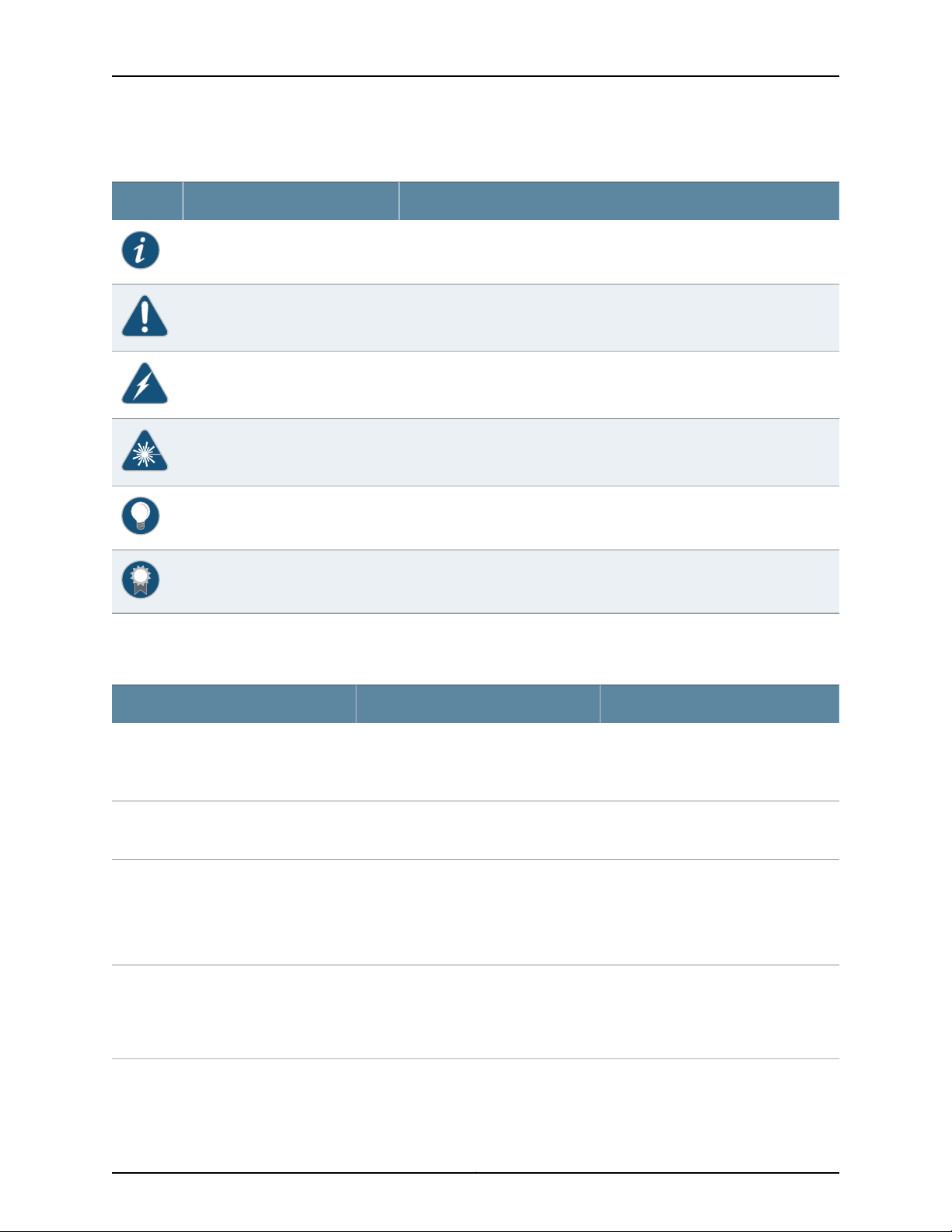
Table 1: Notice Icons
DescriptionMeaningIcon
Indicates important features or instructions.Informational note
Indicates a situation that might result in loss of data or hardware damage.Caution
Alerts you to the risk of personal injury or death.Warning
Alerts you to the risk of personal injury from a laser.Laser warning
Indicates helpful information.Tip
Table 2 on page x defines the text and syntax conventions used in this guide.
Table 2: Text and Syntax Conventions
Represents text that you type.Bold text like this
Fixed-width text like this
Italic text like this
Italic text like this
Represents output that appears on the
terminal screen.
•
Introduces or emphasizes important
new terms.
•
Identifies guide names.
•
Identifies RFC and Internet draft titles.
Represents variables (options for which
you substitute a value) in commands or
configuration statements.
Alerts you to a recommended use or implementation.Best practice
ExamplesDescriptionConvention
To enter configuration mode, type the
configure command:
user@host> configure
user@host> show chassis alarms
No alarms currently active
•
A policy term is a named structure
that defines match conditions and
actions.
•
Junos OS CLI User Guide
•
RFC 1997, BGP Communities Attribute
Configure the machine’s domain name:
[edit]
root@# set system domain-name
domain-name
x
Page 11

Table 2: Text and Syntax Conventions (continued)
Text like this
Represents names of configuration
statements, commands, files, and
directories;configurationhierarchy levels;
or labels on routing platform
components.
About the Documentation
ExamplesDescriptionConvention
•
To configure a stub area, include the
stub statement at the [edit protocols
ospf area area-id] hierarchy level.
•
The console port is labeled CONSOLE.
stub <default-metric metric>;Encloses optional keywords or variables.< > (angle brackets)
| (pipe symbol)
# (pound sign)
[ ] (square brackets)
Indention and braces ( { } )
; (semicolon)
GUI Conventions
Bold text like this
Indicates a choice between the mutually
exclusivekeywordsor variables on either
side of the symbol. The set of choices is
often enclosed in parentheses for clarity.
same line as the configuration statement
to which it applies.
Encloses a variable for which you can
substitute one or more values.
Identifies a level in the configuration
hierarchy.
Identifies a leaf statement at a
configuration hierarchy level.
Representsgraphicaluser interface(GUI)
items you click or select.
broadcast | multicast
(string1 | string2 | string3)
rsvp { # Required for dynamic MPLS onlyIndicates a comment specified on the
community name members [
community-ids ]
[edit]
routing-options {
static {
route default {
nexthop address;
retain;
}
}
}
•
In the Logical Interfaces box, select
All Interfaces.
•
To cancel the configuration, click
Cancel.
> (bold right angle bracket)
Documentation Feedback
We encourage you to provide feedback, comments, and suggestions so that we can
improve the documentation. You can provide feedback by using either of the following
methods:
•
Online feedback rating system—On any page at the Juniper Networks Technical
Documentation site at http://www.juniper.net/techpubs/index.html, simply click the
stars to ratethe content, and use the pop-up form to provide us with information about
your experience. Alternately, you can use the online feedback form at
https://www.juniper.net/cgi-bin/docbugreport/.
Separates levels in a hierarchy of menu
selections.
In the configuration editor hierarchy,
select Protocols>Ospf.
xi
Page 12

LN1000 Mobile Secure Router
•
E-mail—Sendyour comments to techpubs-comments@juniper.net.Include the document
or topic name, URL or page number, and software version (if applicable).
Requesting Technical Support
Technical product support is availablethrough the Juniper Networks Technical Assistance
Center (JTAC). If you are a customer with an active J-Care or Partner Support Service
support contract, or are covered under warranty, and need post-sales technical support,
you can access our tools and resources online or open a case with JTAC.
•
JTAC policies—For a complete understanding of our JTAC procedures and policies,
review the JTAC User Guide located at
http://www.juniper.net/us/en/local/pdf/resource-guides/7100059-en.pdf.
•
Product warranties—For product warranty information, visit
http://www.juniper.net/support/warranty/.
•
JTAC hours of operation—The JTAC centers have resources available 24 hours a day,
7 days a week, 365 days a year.
Self-Help Online Tools and Resources
For quick and easy problem resolution, Juniper Networks has designed an online
self-service portal called the Customer Support Center (CSC) that provides you with the
following features:
•
Find CSC offerings: http://www.juniper.net/customers/support/
•
Search for known bugs: http://www2.juniper.net/kb/
•
Find product documentation: http://www.juniper.net/techpubs/
•
Find solutions and answer questions using our Knowledge Base: http://kb.juniper.net/
•
Download the latest versions of software and review release notes:
http://www.juniper.net/customers/csc/software/
•
Search technical bulletins for relevant hardware and software notifications:
http://kb.juniper.net/InfoCenter/
•
Join and participate in the Juniper Networks Community Forum:
http://www.juniper.net/company/communities/
•
Open a case online in the CSC Case Management tool: http://www.juniper.net/cm/
To verify service entitlement by product serial number,use our Serial Number Entitlement
(SNE) Tool: https://tools.juniper.net/SerialNumberEntitlementSearch/
Opening a Case with JTAC
You can open a case with JTAC on the Web or by telephone.
•
Use the Case Management tool in the CSC at http://www.juniper.net/cm/.
•
Call 1-888-314-JTAC (1-888-314-5822 toll-free in the USA, Canada, and Mexico).
xii
Page 13

About the Documentation
For international or direct-dial options in countries without toll-free numbers, see
http://www.juniper.net/support/requesting-support.html.
xiii
Page 14

LN1000 Mobile Secure Router
xiv
Page 15

PART 1
Overview
•
LN1000 Router Overview on page 3
•
LN1000 Rear Transition Module Overview on page 9
•
LN1000 Router Specifications on page 13
1
Page 16

LN1000 Mobile Secure Router
2
Page 17
CHAPTER 1
Status LED
Router
backplane
connector
g017374
Protective plate over
RJ-45 console port
Ejector latch
LN1000 Router Overview
•
LN1000 Mobile Secure Router Description on page 3
•
LN1000 Mobile Secure Router Models on page 4
•
LN1000 Mobile Secure Router Features on page 5
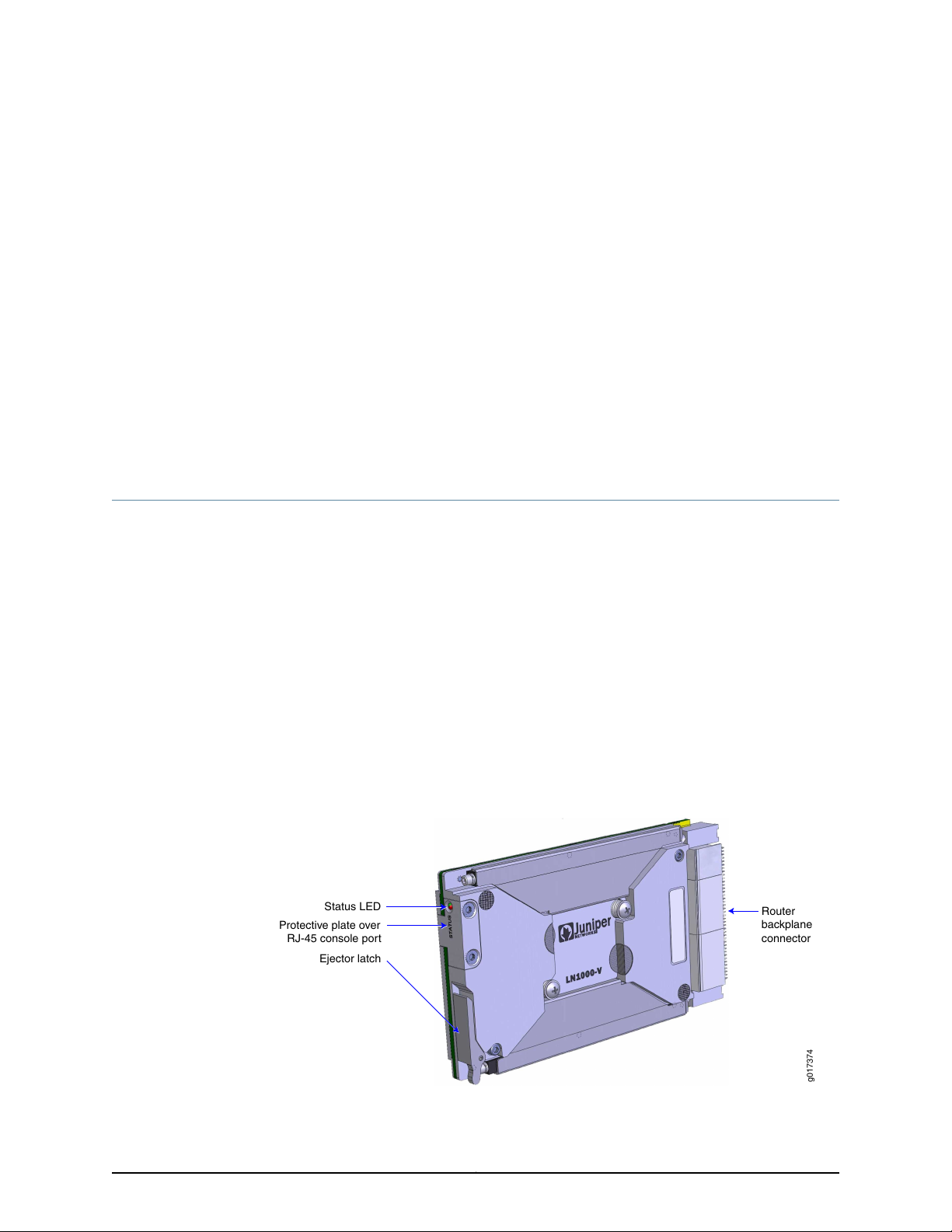
LN1000 Mobile Secure Router Description
The LN1000 Mobile Secure Router is an embedded router that operates in both wire-line
and wireless environments with communication nodes that are either mobile or stationary.
The router provides reliable and secure data, voice, and video services. The LN1000
processes WAN and LAN routing functions. The router offers multiple DiffServ classes
and can interleave lower priority real-time data (voice traffic) with higher priority
non-real-time data. It is developed on 3U compact node slot interface (VITA) architecture
as defined in the VITA 46.0 IEEE 1101.2 specifications and runs Junos OS for routing,
forwarding, and security.
The LN1000 Mobile Secure Router can be used effectively in the following environments:
•
Defense communities
•
Public sector safety organizations, such as first responders
Figure 1: LN1000 Mobile Secure Router
3
Page 18
Chassis midplane
LN1000-V
Rear Transition Module
LN1000-V Router
g017378
LN1000 Mobile Secure Router
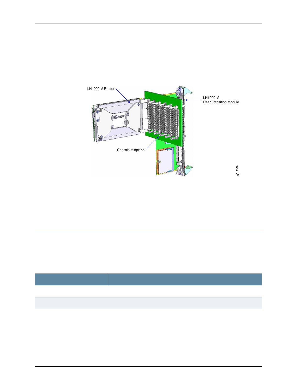
You can install the LN1000 router in a standard VITA 46.0-compliant chassis. Optionally,
you can install it in a VITA 46.0–compliant chassis with a midplane and an LN1000 rear
transition module.
Figure 2: LN1000 Mobile Secure Router Installed with an LN1000 Rear
Transition Module
Related
Documentation
LN1000 Mobile Secure Router Models on page 4•
• LN1000 Mobile Secure Router Features on page 5
• Installing the LN1000 Router on page 24
• LN1000 Rear Transition Module Description on page 9
LN1000 Mobile Secure Router Models
The LN1000 routers are available in different models.
Table 3 on page 4 list the various LN1000 router models available and provide a brief
description of each base unit.
Table 3: LN1000 Router Models
DescriptionModel
Vita ECC3 compliant; -58° F to 212° F (-50° C to +100° C)LN1000-V
Vita ECC2 compliant; -40° F to 185° F (-40° C to +85° C)LN1000-CC
Related
Documentation
LN1000 Mobile Secure Router Description on page 3•
4
Page 19

LN1000 Mobile Secure Router Features
The LN1000 Mobile Secure Router provides the following features:
•
Router Backplane Connector on page 5
•
Ethernet Ports on page 5
•
IPMI Interface on page 5
•
Router Console Port on page 5
•
Tamper-Evident Seals on page 6
Router Backplane Connector
An external interface, located on the back of the LN1000 router, connects the router to
the VITA 46.0–compliant chassis. The router’s P0, P1, and P2 connectors plugging into
the backplane are VITA 46.0–compatible for a 3U peripheral slot with specific key
definitions. The P0 and P2 connectors are keyed per the VITA 46.12 specification. Power
to the LN1000 router is provided through the P0 connector.
Chapter 1: LN1000 Router Overview
Ethernet Ports
IPMI Interface
Router Console Port
The LN1000 router supports up to eight ports of gigabit Ethernet traffic with up to 1024
logical interfaces. The router supports most Layer 2 and Layer 3 protocols, route
redistribution, tunneling, multicast, routine quality of service (QoS), and security.
The eight gigabit Ethernet ports on the LN1000 router are 1000Base-X interfaces with
autonegotiation on by default. The Ethernet ports on the router interface with the chassis
in which it is installed or with the LN1000 rear transition module, if installed in a chassis.
The LN1000 router supports the Intelligent Platform Management Interface (IPMI) in
accordance with the VITA 46.0 specification. The IPMI controller on the LN1000 router
is a secondary controller while the IPMI Shelf Manager operates as the primary controller.
The IPMI Shelf Manager is not supplied by default; it is available as an option.
The router’s RS-232 console port has a baud rate of 9600 8N1 and is located on the left
side of the LN1000 router’s front panel. The console port is used primarily for depot repair.
It is covered by a protective aluminum plate that prevents access to the port. When the
LN1000 router is operational and installed in a chassis, even though you can remove the
protective aluminum plate to access the console port on the router, typically you access
the console port using one of the following methods:
•
On the chassis backplane when the router is installed in VITA 46.0-compliant chassis
•
On the front panel of the rear transition module when the router is installed in a VITA
46.0-compliant chassis with a LN1000 rear transition module
5
Page 20
g017399
Tamper-evident seals
LN1000 Mobile Secure Router
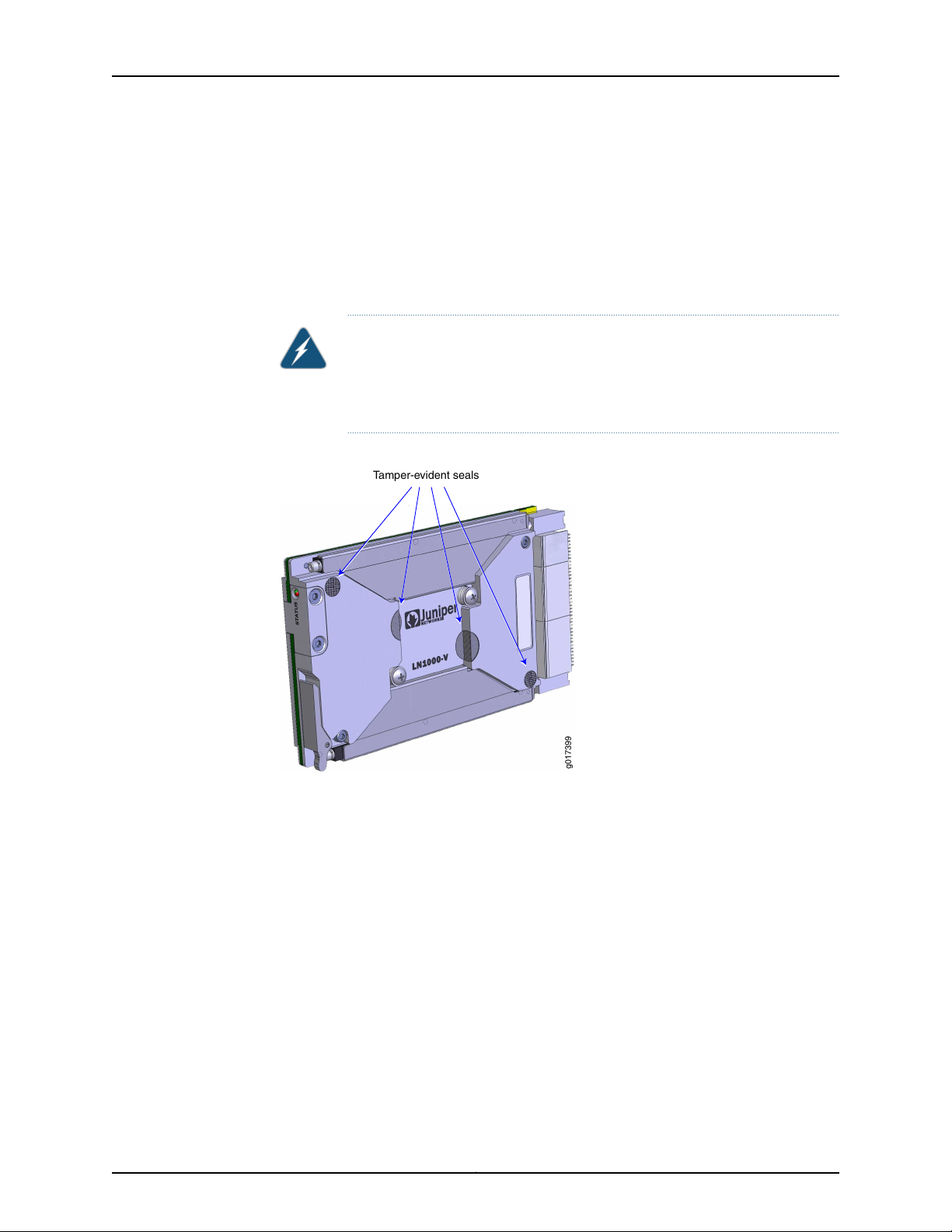
Tamper-Evident Seals
Four tamper-evident seals are affixed to the router to show evidence of tampering with
the router’s internal components. Two small silver disks, which have two small holes in
them, are locatedover the top-leftand bottom-right screws that hold the router assembly
together. Two larger, bright silver seals span the processor backer plate and primary side
cover.
WARNING: If any of these seals are removed or peeled off the router, the
router’s internal components can be exposed to electrostatic discharge
(ESD), compromising the integrity of the router, which voids the router’s
warranty.
Figure 3: Tamper-Evident Seals
6
An ESD warning label is located on the back of the router.
Page 21

Figure 4: ESD Warning Label
g017400
ESD label
Chapter 1: LN1000 Router Overview
Related
Documentation
• LN1000 Mobile Secure Router Description on page 3
• LN1000 Rear Transition Module Description on page 9
• Installing the LN1000 Router on page 24
7
Page 22

LN1000 Mobile Secure Router
8
Page 23

CHAPTER 2
LN1000 Rear Transition Module Overview
•
LN1000 Rear Transition Module Description on page 9
•
LN1000 Rear Transition Module Features on page 9
LN1000 Rear Transition Module Description
The LN1000 rear transition module is a fully compatible, carrier-grade VITA
46.10-compliant I/O rear transition module for the LN1000 Mobile Secure Router. The
6 rack unit (6RU) form factor, single-slot rear transition module is fully compliant with
the PICMG 2.0 Revision 3.0 specification.
The LN1000 rear transition module requires an VITA 46.0-compliant chassis with a
midplane that accommodates front and rear board installations. The primary purpose
of this module is to provide rear access connections to the LN1000 router in a test or
repair environment.
LN1000 Rear Transition Module Features
•
LN1000 Rear Transition Module Backplane Connector on page 9
•
LN1000 Rear Transition Module Console Ports on page 10
•
IPMI Shelf Manager on page 11
•
LN1000 Rear Transition Module Ethernet Ports on page 11
•
LN1000 Rear Transition Module Switch Settings on page 11
LN1000 Rear Transition Module Backplane Connector
The connector on the LN1000 rear transition module provides the ability to configure the
router. It also provides:
•
Console port access
•
IPMI signals
•
USB port access
•
Ethernet port access
9
Page 24

g017380
Connector IPMI Shelf Manager
g017379
Ejector latchEjector latch
ShMM
IPMC
NPU
ACTLINK
PWR OK
Ethernet ports
USB port
023567 4 1
Locking screwLocking screw
LN1000 Mobile Secure Router
Figure 5: LN1000 Rear Transition Module — Back View
LN1000 Rear Transition Module Console Ports
The shMM console port is the console port for the optional shMM module on the RTM.
The settings are baud rate of 19200 8N1, no flow control. You can use this port to send
and receive debug console commands to and from the shelf manager.
The IPMC console port is the console port for the IPMC controller on the LN1000 board.
The settings are baud rate of 115200 8N1, no flow control. This is a debug output only
port.
The RS-232 console port, labeled NPU, accepts an RJ-45 connector and is located on
the front panel of the LN1000 rear transition module. The settings are baud rate of 9600
8N1, no flow control. You can use this console port to monitor system startup and for
system repair. This console port is also available from the front panel of the LN1000
router.
Figure 6: LN1000 Rear Transition Module — Front Panel
Table 4: Pinouts for the RJ-45 (NPU), shMM, and IPMC Console Port Connectors
DescriptionSettingPin
No connect.NC1
Transmit data into the LN1000 router.RXD2
Transmit data out from the LN1000 router.TXD3
No connect.NC4
Ground.GND5
10
No connect.NC6
Page 25

Chapter 2: LN1000 Rear Transition Module Overview
Table 4: Pinouts for the RJ-45 (NPU), shMM, and IPMC Console Port Connectors (continued)
DescriptionSettingPin
No connect.NC7
No connect.NC8
IPMI Shelf Manager
The optional IPMI shelf management module provides intelligent management functions
for the rear transition module, including sensing the presence of the LN1000 router, and
configuring and booting the router when it is installed in the LN1000 rear transition module.
NOTE: The IPMI shelf manager is not installed in the LN1000 rear transition
module by default.
The IPMI shelf manager:
•
Is implemented as a Small Outline Dual Inline Memory Module (SODIMM) form factor
•
Is installed in a board-mounted SODIMM connector on the LN1000 rear transition
module
•
Complies with the PICMG 3.0 R2.0 and IPMI v1.5 and implements the IPMI v1.5
functionality on the LN1000 rear transition module
•
Communicates with the IPMI controller on the LN1000 router
LN1000 Rear Transition Module Ethernet Ports
The LN1000 rear transition module includes eight gigabit Ethernet ports to provide
Ethernet connectivity.These eight ports connect directly to the chassis midplane, enabling
you to connect directly to the Ethernet ports on the LN1000 router. Ethernet Port 0 is
typically used as the management port. Ports 1 through 7 are typically used for data
transfer.
NOTE: There is no dedicated management port on the LN1000 router.
LN1000 Rear Transition Module Switch Settings
The switch banks on the rear transition module are set as follows:
DescriptionSwitch Bank
No user control. All switches are off for normal operation.S1
11
Page 26

LN1000 Mobile Secure Router
S2
DescriptionSwitch Bank
•
Switch 1, WD_INH_L. This switch has no effect.
•
Switch 2: NVMRO. This signal controls the ability to write to the system non-volatile
memory. This switch is off to allow read-only access to system non-volatile memory.
Set this switch to on to enable writing to non-volatile memory.
If you set the NVRMO switch to off, note the following precautions:
•
Do not boot from USB storage device; router performance will be degraded.
•
Do not use J-Web; unpredictable results may occur.
•
Do not use the CLI command request system software add; unpredictable results may
occur.
•
Switches 3 and 4 must be off for normal operation.
12
Page 27

CHAPTER 3
LN1000 Router Specifications
•
LN1000 Mobile Secure Router Physical Specifications on page 13
•
LN1000 Router Power Requirements on page 13
LN1000 Mobile Secure Router Physical Specifications
Table 5: LN1000 Router Physical Specifications
SpecificationCategory
100 mm/3.937 inchesHeight
0.85 inch pitch (4.25 HP)Card pitch
160 mm/6.3 inchesLength
VITA 48.2, 3U formatSize
35WMaximum power dissipation
Related
Documentation
LN1000 Router Power Requirements on page 13•
• LN1000 Mobile Secure Router Features on page 5
• LN1000 Mobile Secure Router Description on page 3
LN1000 Router Power Requirements
Power for the LN1000 Mobile Secure Router is supplied by the chassis in which it is
installed when the power to the chassis is turned on. The chassis delivers 5.0 V and 3.3
V power to the LN1000 router through a standard IDE 4-pin connector.
Related
Documentation
• Powering On the LN1000 Mobile Secure Router on page 25
• SPOST and POST Diagnostic Tests on page 35
• LN1000 Mobile Secure Router Features on page 5
0.68 kg/1.5 lbWeight
13
Page 28

LN1000 Mobile Secure Router
14
Page 29

PART 2
Safety
•
General Safety Information on page 17
15
Page 30

LN1000 Mobile Secure Router
16
Page 31

CHAPTER 4
General Safety Information
•
Safety Requirements, Warnings, and Guidelines on page 17
Safety Requirements, Warnings, and Guidelines
The router module is designed to protect against the risk of electrical shock and other
hazards during installation, operation, and maintenance, and under likely fault conditions,
including human error. It complies with grounding requirements of NFPA 70-93, article
250. As a precautionary measure to avoid harm to yourself as you install and maintain
the router module, follow the guidelines for working near and with electrical equipment,
as well as the safety procedures for working with Internet routers.
17
Page 32

LN1000 Mobile Secure Router
18
Page 33

PART 3
Installation
•
Unpacking and Inspecting the Hardware on page 21
•
Installing the LN1000 Mobile Secure Router on page 23
•
Installing the LN1000 Rear Transition Module on page 27
19
Page 34

LN1000 Mobile Secure Router
20
Page 35

CHAPTER 5
Unpacking and Inspecting the Hardware
•
Unpacking the LN1000 Router on page 21
•
Unpacking the LN1000 Rear Transition Module on page 21
•
Inspecting the Hardware on page 22
•
If You Detect or Suspect Damage on page 22
Unpacking the LN1000 Router
The router is shipped in a cardboard carton, secured with packing material.
Before you begin unpacking the router, be sure you have a utility knife to open the box.
NOTE: Be sure to retain all packaging materials in the event that you need
to return items for repair.
To unpack the LN1000 router:
1. Open the box from the top to access the router in its protective package.
2. Remove the router and its protective package from the box.
3. Remove the protective packaging from the router.
Related
Documentation
Before You Install the LN1000 Router on page 23•
• Inspecting the Hardware on page 22
• Installing the LN1000 Router on page 24
Unpacking the LN1000 Rear Transition Module
Before you begin unpacking the LN1000 rear transition module, be sure you have a utility
knife to open the box.
NOTE: Be sure to retain all packaging materials in the event that you need
to return items for repair.
21
Page 36

LN1000 Mobile Secure Router
To unpack the LN1000 rear transition module:
1. Open the outer box from the top.
2. Remove the accessories from the box.
The accessories are located between the outer box and the inner box that contains
the LN1000 rear transition module. Accessories include an RJ-45-to-DB-9 adapter.
3. Remove the inner box that contains the LN1000 rear transition module.
4. Remove the LN1000 rear transition module from the box and place it in the location
you selected.
Inspecting the Hardware
After you remove the equipment from the shipping container:
•
Confirm the contents of the container.
•
Inspect all external surfaces and external connectors for visible signs of damage.
•
Inspect all accessories shipped with each unit.
•
Document any damage noted during your inspection.
Related
Documentation
If You Detect or Suspect Damage on page 22•
• Before You Install the LN1000 Router on page 23
• Unpacking the LN1000 Router on page 21
If You Detect or Suspect Damage
If you detect or suspect damage to any equipment:
•
Contact the shipper responsible for delivery, and formally report the damage.
•
Contact your Juniper Networks sales representative or reseller at
http://www.juniper.net/in/en/contact-us/.
Related
Documentation
• Information You Might Need to Supply to JTAC on page 45
• Before You Install the LN1000 Router on page 23
• Unpacking the LN1000 Router on page 21
22
Page 37

CHAPTER 6
Installing the LN1000 Mobile Secure
Router
•
Before You Install the LN1000 Router on page 23
•
Installing the LN1000 Router on page 24
•
Removing the LN1000 Mobile Secure Router on page 24
•
Powering On the LN1000 Mobile Secure Router on page 25
Before You Install the LN1000 Router
Before installing the LN1000 router, be sure you have:
•
A 3/32 Allen wrench with a torque of 7 inch-pounds (in-lb).
•
Copper or fiber optic Ethernet cables (up to nine for each router)
NOTE: You must provide up to nine Ethernet cables.
Related
Documentation
•
Power to the chassis turned off
LN1000 Mobile Secure Router Description on page 3•
• Unpacking the LN1000 Router on page 21
• Inspecting the Hardware on page 22
23
Page 38

g017375
RJ-45 Connector for debug
Ejector latch
Wedge lock
Status LED
Wedge lock
Guide rail Guide rail
LN1000 Mobile Secure Router
Installing the LN1000 Router
Figure 7: LN1000 Mobile Secure Router — Front Panel
Related
Documentation
To install the LN1000 router in a VITA 46.0–compliant chassis:
1. Insert the router into the guide rails located on the front of the chassis.
2. Slide the router forward until the connector on the router’s back panel contacts the
connector in the chassis.
3. Push in the injector/ejector latch on the right side of the router front panel to complete
the installation. If your chassis is not equipped to utilize the injector/ejector latch to
assist in insertion, press the front surface of the LN1000 router until its connector is
fully seated in the chassis.
4. Using the 3/32 Allen wrench, tighten the two wedge locks to a torque of 7 in-lb.
CAUTION: The guide rails provide cooling to the conduction-cooledrouter.
If you do not properly tighten the wedge locks, the router can overheat
and fail.
Before You Install the LN1000 Router on page 23•
• Powering On the LN1000 Mobile Secure Router on page 25
• Unpacking the LN1000 Router on page 21
Removing the LN1000 Mobile Secure Router
The LN1000 router is hot-swappable; power can be left on while you remove or replace
a router module without damage to the router or backplane.
24
Page 39

Chapter 6: Installing the LN1000 Mobile Secure Router
To remove the router from the chassis:
1. Using a 3/32 Allen wrench, loosen the two wedge locks on the front panel of the
LN1000 router.
2. Lift the injector/ejector latch on the right side of the router front panel to disengage
the connector on the router from the backplane connector.
3. Slide the router out of the guide rails.
Related
Documentation
LN1000 Mobile Secure Router Description on page 3•
• Before You Install the LN1000 Router on page 23
• Powering On the LN1000 Mobile Secure Router on page 25
Powering On the LN1000 Mobile Secure Router
The LN1000 router derives its power from the chassis in which it is installed; it
automatically powers on when inserted into the connector in the VITA 46.0-compliant
chassis.
Monitor router startup on the console and the LED on the front panel of the LN1000
router to verify that the router is booting properly.
As a standard part of the boot process, the router runs startup power-on self test (SPOST)
and then power-on self test (POST) diagnostics. A successful startup looks similar to
the following example:
CPU Memory (Data32: 00000000-0007ffff) test completed, 1 pass, 0 errors
CPU Memory (Data32: 0f000000-0fffffff) test completed, 1 pass, 0 errors
CPU Memory (Addr32: 00000000-0007ffff) test completed, 1 pass, 0 errors
CPU Memory (Addr32: 0f000000-0fffffff) test completed, 1 pass, 0 errors
Boot Flash: 16 MB in 131 Sectors (portwidth: 16bit chipwidth: 16bit)
OCTEON CN56XX pass 2.0, Core clock: 600 MHz, DDR clock: 266 MHz
Initializing USB
Device 1:
Product DOTG Root Hub
Device 2:
Manufacturer
Product USB Flash Memory
SerialNumber 00147808E485C92043770566
Initializing IDE
Initializing FPGA
Programming /cf/usr/share/pfe/firmware/563-029572.bit: 2067590 bytes
Programmed successfully (time: 883475051 ticks)
Checking for init_data
No init_data
PCIe: Waiting for port 0 link
PCIe: Port 0 link active, 1 lanes
Probing PCIe port 0
25
Page 40

LN1000 Mobile Secure Router
0:00:00.0 0x003b1304
PCIe port 0 had 1 busses
HWA FPGA Version 0x0004090900000013
PCIe: Waiting for port 1 link
PCIe: Port 1 link active, 4 lanes
Probing PCIe port 1
1:00:00.0 0x0009184e
PCIe port 1 had 1 busses
IDP Revision Date-Time: 05/28/08-18:00:00
Enumeration took 0 reboots
Juniper LN1000-V revision 2.0, Serial# ************
Juniper Part # 710-027379 Bootstrap version 10.0I
Build: 10.0B3.7 #0: 2009-09-25 16:36:56 UTC
builder@ormonth.juniper.net
SDRAM: 1024 MB
Boot flash: 16 MB @ 0x1fc00000
IDE flash: 977.4 MB (2001888 x 512)
USB: 1.8 GB (3911616 x 512)
current_dev: ide
coremask: 0xfff (12 cores)
resetmask: 0xffe (1 cores running)
reset: Hard
NVMRO: Write-enabled
watchdog: Armed
FPGA: Enabled
Related
Documentation
Hit any key to stop autoboot: 10
IPMC test
IPMC test completed, 1 pass, 0 errors, 0 warnings
BOOT >
For normal operation, allow the autoboot to proceed. Full POST diagnostics then run,
and the system starts Junos OS normally. If detaileddiagnostics must be run, or if alternate
media (for example, a USB storage device) must be booted, press ENTER during the
10-second count-down. The following bootstrap prompt is displayed:
BOOT>
If POST diagnostics or the bootstrap sequence fails, this prompt is redisplayed, and the
front panel LED lights red.
You are now ready to configure and operate the router.
• LN1000 Router Power Requirements on page 13
• SPOST and POST Diagnostic Tests on page 35
• LN1000 Rear Transition Module Front Panel Status LEDs on page 43
26
Page 41

CHAPTER 7
Installing the LN1000 Rear Transition Module
•
Installing the LN1000 Rear Transition Module on page 27
•
Installing an SFP Transceiver in an LN1000 RTM on page 28
•
Removing an SFP from an LN1000 RTM on page 30
•
Cabling the LN1000 Rear Transition Module on page 31
Installing the LN1000 Rear Transition Module
To install the LN1000 rear transition module into a VITA 46.0-compliant chassis:
1. Verify that you have taken the necessary antistatic precautions.
2. On the back of the VITA 46.0-compliant chassis, choose an appropriate slot for the
rear transition module.
The LN1000 rear transition module must be installed inline behind the designated
locationwhere you plan to install the LN1000 router.For example, if the LN1000 router
is to be installed in slot 3, the rear transition module must be installed in the back of
the chassis in slot 3.
27
Page 42

Chassis midplane
LN1000-V
Rear Transition Module
LN1000-V Router
g017378
LN1000 Mobile Secure Router
Figure 8: Location of the RearTransitionModule in Relation to the LN1000
Router
3. Remove the slot filler panel from the selected node board slot, if necessary.
4. Prepare the rear transition module by manually loosening the locking screws and
opening the injector/ejector latches at the top and bottom of the rear transition
module.
5. Carefully align the edges of the module with the guides in the appropriate slot.
6. Taking care to keep the module aligned in the guides, slide the module in until the
injector/ejector latches engage in the chassis retention bars.
7. Simultaneously push in the rear transition module and rotate the injector/ejector
mechanisms inward to their closed positions to seat the midplane connectors.
8. Tighten the module retention screws to ensure that the rear transition module is
secured into the shelf.
Installing an SFP Transceiver in an LN1000 RTM
You can install up to eight SFP transceivers in the LN1000 rear transition module (RTM).
The SFP transceiversare hot—removableand hot-insertable. You can remove and replace
them without powering off the LN1000 router or disrupting router functions.
WARNING: Do not look directly into transceiversor into the ends of fiber-optic
cables connected to a transceiver. Fiber-optic transceivers emit laser light
that can damage your eyes.
28
CAUTION:
Page 43

g001855
Connector
Locking pin
Chapter 7: Installing the LN1000 Rear Transition Module
When handling fiber-optic transceivers and fiber-optic cable, observe the
following precautions:
•
Do not leave a fiber-optic transceiver uncovered except when inserting or
removing cable. The safety cap keeps the port clean and prevents
accidental exposure to laser light.
•
Do not bend fiber-optic cable beyond its minimum bend radius. An arc
smaller than a few inches in diameter can damage the cable and cause
problems that are difficult to diagnose.
•
Do not let fiber-optic cable hang free from the connector. Do not allow
fastenedloopsof cable to dangle, which stresses the cable at the fastening
point.
Figure 9: Small Form-Factor Pluggable (SFP)
To install an SFP transceiver in the LN1000 RTM:
1. Attachan electrostatic discharge (ESD) grounding strap to your bare wrist, and connect
the strap to one of the ESD points on the chassis.
2. Verify that a rubber safety cap covers the SFP transceiver, installing one if necessary.
3. Orient the SFP over the port in the RTM so that the connector end will enter the slot
first and the SFP connector faces the appropriate direction:
4. Slide the SFP into the slot. If there is resistance, remove the SFP and flip it so that the
connector faces the other direction.
5. Remove the rubber safety cap from the transceiver and the end of the cable, and
insert the cable into the transceiver.
6. Arrange the cable in the cable management system to prevent the cable from
dislodging or developing stress points. Secure the cable so that it is not supporting its
own weight as it hangs to the floor. Place excess cable out of the way in a neatly coiled
loop in the cable management system. Placing fastenerson the loop helps to maintain
its shape.
7. Verify that the SFP is installed by entering the CLI show chassis hardware detail
command. Output will display as follows:
root@spencer# run show chassis hardware
Hardware inventory:
Item Version Part number Serial number Description
29
Page 44

g001855
Connector
Locking pin
LN1000 Mobile Secure Router
Chassis BF1809AG0055 LN1000-v
Routing Engine REV 06 710-027379 DY7841 LN1000-V
FPC 0 FPC
PIC 0 8x GE Base PIC
Xcvr 0 REV 01 740-026948 UFA03J9 SFP-T
Xcvr 1 REV 01 740-026948 UFA03L0 SFP-T
Xcvr 2 REV 01 740-027085 UFA03UW SFP-T
Xcvr 3 REV 01 740-011782 PB82D10 SFP-SX
Xcvr 4 REV 01 740-011782 PB82D13 SFP-SX
Xcvr 5 REV 01 740-011613 AM0819S9RPK SFP-SX
Xcvr 6 REV 01 740-011613 AM0821SA1UL SFP-SX
Xcvr 7 REV 01 740-011613 AM0819S9RPC SFP-SX
Power Supply 0
Removing an SFP from an LN1000 RTM
WARNING: Do not look directly into transceiversor into the ends of fiber-optic
cables connected to a transceiver. Fiber-optic transceivers emit laser light
that can damage your eyes.
CAUTION:
When handling fiber-optic transceivers and fiber-optic cable, observe the
following precautions:
•
Do not leave a fiber-optic transceiver uncovered except when inserting or
removing cable. The safety cap keeps the port clean and prevents
accidental exposure to laser light.
•
Do not bend fiber-optic cable beyond its minimum bend radius. An arc
smaller than a few inches in diameter can damage the cable and cause
problems that are difficult to diagnose.
•
Do not let fiber-optic cable hang free from the connector. Do not allow
fastenedloopsof cable to dangle, which stresses the cable at the fastening
point.
Figure 10: Small Form-Factor Pluggable (SFP)
30
Page 45

Chapter 7: Installing the LN1000 Rear Transition Module
To remove an SFP:
1. Place an electrostatic bag or antistatic mat on a flat, stable surface to receive the
SFP. Have ready a rubber safety cap for the SFP transceiver and the cable.
2. Attach an electrostaticdischarge(ESD) grounding strap to your bare wrist, and connect
the strap to one of the ESD points on the chassis.
3. Label the cable connected to the SFP so that you can later reconnect it to the correct
SFP.
4. Disconnect the cable from the SFP. Immediately cover the transceiver and the end
of the cable with a rubber safety cap.
5. Arrange the cable to prevent it from dislodging or developing stress points. Secure
the cable so that it is not supporting its own weight as it hangs to the floor. Place
excesscable out of the way in a neatly coiled loop. Placing fasteners on the loop helps
to maintain its shape.
6. Pull the ejector handle away from the SFP faceplate to unseat the SFP from the RTM.
Pull the SFP out of the RTM and place it on the antistatic mat or in the electrostatic
bag.
CAUTION: After removing a transceiver from the chassis, wait at least 30
seconds before reinserting it or inserting a transceiver into a different slot.
Issue the show chassis hardware detail command to verify the installed
transceivers.
Cabling the LN1000 Rear Transition Module
To cable the LN1000 rear transition module, you need the following items:
•
RJ-45-to-DB-9 adapter (provided)
•
External power supply
•
Up to nine copper Ethernet cables with RJ-45 connectors: one cable to connect to the
console port and eight cables to connect to the gigabit Ethernet ports. (These cables
are not provided with the router hardware.)
To cable the LN1000 rear transition module:
1. Insert one end of the console cable with an RJ-45 connector into the NPU console
connector port on the front panel of the rear transition module.
2. Insert the RJ-45-to-DB-9 adapter on the other end of the console cable.
3. Insert the DB-9 adapter into the serial port on your PC.
4. Insert the RJ-45 connectors on the copper Ethernet cables into the Ethernet ports on
the front panel of the rear transition module.
31
Page 46

LN1000 Mobile Secure Router
NOTE: The USB connector on the front panel of the rear transition module
accepts a USB storage device. You can boot from a USB storage device
in the event of system damage, or for updating system software. It is not
needed for normal operation.
32
Page 47

PART 4
Troubleshooting
•
Troubleshooting Router Boot-Up and Operation on page 35
•
Contacting Customer Support on page 45
33
Page 48

LN1000 Mobile Secure Router
34
Page 49

CHAPTER 8
Troubleshooting Router Boot-Up and
Operation
•
SPOST and POST Diagnostic Tests on page 35
•
Accelerating the LN Series Router Boot-Up Process on page 36
•
Accessing the Extended Diagnostic Tests on page 41
•
LN1000 Mobile Secure Router Status LED on page 42
•
LN1000 Rear Transition Module Front Panel Status LEDs on page 43
SPOST and POST Diagnostic Tests
Startup power-on self test (SPOST) and power-on self test (POST) diagnostic tests run
automatically on the LN1000 Mobile Secure Router as part of the boot-up process at
every power on, reset, or warm reboot.
•
SPOST diagnostics consist of a limited suite of quick diagnostics that ensure that
systemcomponents required for Boot Loader and diagnostics relocation and execution
from RAM are working without error.
Related
Documentation
•
POST diagnostics consist of a suite of quick diagnostics that ensure that components
of the system are working without error before trying to load and execute Junos OS.
PASS/FAIL test results for the SPOST and POST diagnostics are reported by means of
the front panel LED, console port, and IPMI.
In the event that SPOST, POST, or the bootstrap sequence reports a failure and the front
panel LED lights red, extended diagnostic tests are available. For information about
running extended diagnostic tests, contact Juniper Networks at
http://www.juniper.net/in/en/contact-us/.
LN1000 Mobile Secure Router Status LED on page 42•
• Powering On the LN1000 Mobile Secure Router on page 25
• LN1000 Router Power Requirements on page 13
35
Page 50

LN1000 Mobile Secure Router
Accelerating the LN Series Router Boot-Up Process
To minimize the time required for an LN Series router to become operational, you can
configure these BOOT features to accelerate the startup process:
•
Disable or enable power-on self test (POST) using the no_run_post environmental
variable.
•
Disable or enable file system cleanup using the fs_clean_boot environmental variable.
•
Remove temporary files left over from the IDP security package installation.
BEST PRACTICE: We recommend that you only enable the no_run_post and
the fs_clean_boot environmental variables in networkswhen the time to boot
the platform is critical to system operations.
These options are not mutually exclusive and not linked. You can choose to
set both options, set only one option, or set neither of the options. If neither
option is set, the LN Series router’s default behavior remains unchanged;
POST runs automatically, and the optional file system cleanup is not
performed.
This section contains the following topics:
•
Accessing the LN Series Router BOOT> Prompt on page 36
•
Disabling or Enabling POST on page 38
•
Disabling or Enabling File System Cleanup on page 39
•
Removing Temporary IDP Package Installation Files on page 41
Accessing the LN Series Router BOOT> Prompt
You set the no_run_post and the fs_clean_boot environmental variables from the BOOT>
prompt.
To access the LN Series router BOOT> prompt:
1. Obtain console access to the LN Series router.
2. Start the boot cycle by rebooting or re-powering the router by entering the request
system reboot command at the console and answering yes to reboot the system
prompt. When the Boot Flash information displays on the console, press the space
bar.
lab@md-ln4-2> request system reboot
Reboot the system ? [yes,no] (no) yes
Shutdown NOW!
[pid 1938]
36
lab@md-ln4-2>
*** FINAL System shutdown message from lab@md-ln4-2 ***
Page 51

Chapter 8: Troubleshooting Router Boot-Up and Operation
System going down IMMEDIATELY
JWaiting (max 60 seconds) for system process `vnlru' to stop...done
Waiting (max 60 seconds) for system process `vnlru_mem' to stop...done
Waiting (max 60 seconds) for system process `bufdaemon' to stop...done
Waiting (max 60 seconds) for system process `syncer' to stop...
Syncing disks, vnodes remaining...0 0 0 0 done
syncing disks... All buffers synced.
Uptime: 14h48m47s
Rebooting...
cpu_reset: Stopping other CPUs
Boot Flash: 16 MB in 131 Sectors (portwidth: 16bit chipwidth: 16bit)
OCTEON CN56XX pass 2.1, Core clock: 600 MHz, DDR clock: 266 MHz
Device 1:
Product DWC OTG root hub
Initializing IDE
Initializing FPGA
Programming /cf/usr/share/pfe/firmware/563-029572.bit: 2067591 bytes
Programmed successfully (time: 883972430 ticks)
PCIe: Waiting for port 0 link
PCIe: Port 0 link active, 1 lanes
0:00:00.0 0x003b1304
HWA FPGA Version 0x0011081200000055
PCIe: Waiting for port 1 link
PCIe: Port 1 link active, 4 lanes
1:00:00.0 0x0009184e
IDP Revision Date-Time: 05/28/08-18:00:00
Juniper LN1000-V revision 3.7, Serial# BF1111AG0006
Juniper Part # 710-027379
Bootstrap: #1.6
Loader: #2.5 12.1I20131213_1517_rwinter 2013-12-13 15:19:38 UTC
rwinter@svl-junos-d080.juniper.net
IPMC: 1.0.19
IPMC_RB: 1.0.19
SDRAM: 1024 MB
Boot flash: 16 MB @ 0x1fc00000
IDE flash: 977.4 MB (2001888 x 512)
USB: not available
current_dev: ide
coremask: 0xfff (12 cores)
reset: Soft
NVMRO: Write-enabled
watchdog: Armed
FPGA: Enabled
FS Cleanup: Disabled
POST: Enabled
Firmware Image Status:
Primary Bootstrap: UP TO DATE
Secondary Loader0: UP TO DATE
37
Page 52

LN1000 Mobile Secure Router
Secondary Loader1: UP TO DATE
IPMC Firmware: UP TO DATE
IPMC_RB Firmware: UP TO DATE
Hit any key to stop autoboot: 1
IPMC test
IPMC test completed, 1 pass, 0 errors, 0 warnings
BOOT >
3. After pressing the space bar, the process continues performing some system tests,
and then the boot process stops at the BOOT> prompt.
4. For available commands, enter help or ? at the BOOT> prompt.
Disabling or Enabling POST
Disabling POST
To disable the POST feature:
BOOT> setenv no_run_post 1
BOOT> saveenv
BOOT> reset
NOTE: Only the first character of the environmental variable is evaluated. If
the variable is not set, or if the first character of the variable’s value is zero
(0), then the default behavior for POST (runs automatically) and file system
cleanup (not performed) is followed.
When you disable POST, the standard set of POST diagnostic tests are skipped. The
following sample console output shows that the POST feature is disabled:
....
NVMRO: Write-enabled
watchdog: Armed
FPGA: Enabled
FS Cleanup: Disabled
POST: Disabled
Firmware Image Status:
Primary Bootstrap: UP TO DATE
....
IPMC test completed, 1 pass, 0 errors, 0 warnings
Skipping POST
38
Booting...
Enabling POST
To enable the POST feature and run the full set of POST diagnostic tests during the
boot-up process:
Page 53

Chapter 8: Troubleshooting Router Boot-Up and Operation
NOTE: The POST feature’s default setting is enabled.
BOOT> unsetenv no_run_post
BOOT> saveenv
BOOT> reset
or
BOOT> setenv no_run_post 0
BOOT> saveenv
BOOT> reset
When you enable POST, the full set of POST diagnostic tests run. The following sample
console output shows that the POST feature is enabled:
....
NVMRO: Write-enabled
watchdog: Armed
FPGA: Enabled
FS Cleanup: Disabled
POST: Enabled
Firmware Image Status:
Primary Bootstrap: UP TO DATE
....
Disabling or Enabling File System Cleanup
Disabling File System Cleanup
To disable the file system cleanup feature:
NOTE: The file system cleanup’s default setting is disabled.
BOOT> unsetenv fs_clean_boot
BOOT> saveenv
BOOT> reset
or
BOOT> setenv fs_clean_boot 0
BOOT> saveenv
BOOT> reset
When you disable the file system cleanup feature, no files are deleted during the boot
process. The following sample console output shows that the file system cleanup feature
is disabled:
....
NVMRO: Write-enabled
watchdog: Armed
FPGA: Enabled
FS Cleanup: Disabled
POST: Enabled
39
Page 54

LN1000 Mobile Secure Router
Firmware Image Status:
Primary Bootstrap: UP TO DATE
....
BESTPRACTICE: We recommend that you disable file system cleanup before
performing a Junos OS upgrade. If you enable file systemcleanup,you cannot
roll back Junos OS to a previous version, and in case of an upgrade failure,
can result in a non-functioning router. By setting disabling file system cleanup,
you maintain the option of having a recoverable rollback image available, if
necessary.
Enabling File System Cleanup
When you enable the file system cleanup feature, certain unnecessary files are identified
and deleted early in the boot process. To enable the file system cleanup feature to select
and delete files:
BOOT> setenv fs_clean_boot 1
BOOT> saveenv
BOOT> reset
When you enable file system cleanup, temporary, log, and other unnecessary files are
identified and deleted. The following sample console output shows that the file system
cleanup feature is enabled:
....
NVMRO: Write-enabled
watchdog: Armed
FPGA: Enabled
FS Cleanup: Enabled
POST: Enabled
Firmware Image Status:
Primary Bootstrap: UP TO DATE
....
WARNING: Autorecovery feature is not available as
this system does not support a recovery partition
Starting filesystem cleanup ... Done
Loading configuration ...
....
This additional sample console output shows the file system cleanup feature is enabled
with non-volatile memory read-only (NVMRO) switch enabled as well:
....
NVMRO: Read-only
watchdog: Armed
FPGA: Enabled
FS Cleanup: Enabled
POST: Enabled
40
Firmware Image Status:
Primary Bootstrap: UP TO DATE
....
Remounting directory /cf/var/home: 5MBytes
Preserving directory /cf/etc: 5MBytes
Page 55

Chapter 8: Troubleshooting Router Boot-Up and Operation
Filesystem cleanup skipped - NVMRO Read-only
Loading configuration ...
....
No files are deleted when NVMRO is set to Read-only regardless of the fs_clean_boot
setting.
After the system completes its boot process, you can review the list of removed files by
reading the file_cleanup.log file:
root@ln1000% cat /var/tmp/file_cleanup.log
/cf/var/log/appidd
/cf/var/log/bin_messages
/cf/var/log/chassisd
/cf/var/log/cosd
/cf/var/log/dcd
.....
/cf/var/tmp/policy_status
/cf/var/tmp/rtsdb/if-rtsdb
/cf/var/tmp/spu_kmd_init
/cf/var/tmp/vpn_tunnel_orig.id
root@ln1000%
To determine the value of the fs_clean_boot environmental variable using the CLI:
root@ln1000% sysctl kern.fs_clean_boot
kern.fs_clean_boot: 1
root@ln1000%
Removing Temporary IDP Package Installation Files
The fs_clean_boot option does not remove temporary files left over from the IDP security
packageinstallation.To remove the temporary files, run the separate IDP cleanup request
after installing or upgrading the IDP package:
user@ln1000>request security idp storage-cleanup downloaded-files
Successfully deleted downloaded secdb files
user@ln1000>
Related
Documentation
Powering On the LN1000 Mobile Secure Router on page 25•
• SPOST and POST Diagnostic Tests on page 35
• LN1000 Router Power Requirements on page 13
Accessing the Extended Diagnostic Tests
From the bootstrap prompt, you can enter the Diagnostic CLI menu interface and navigate
through the interfaceto executediagnostic commands. Otherwise, you can use command
scripting at the bootstrap prompt.
The Diagnostic CLI menu interface combines all diagnostic tests and flags into a menu
structure that is easy to navigate and provides access to all available diagnostic
commands. You enter the Diagnostic CLI menu interface from the bootstrap prompt,
BOOT>, by entering the diags command.
41
Page 56

LN1000 Mobile Secure Router
You access submenus by entering the abbreviated menu name. For example, to enter
the Flags menu, from the Diagnostic CLI menu interface enter the flags command.
To return to a higher level menu, press Ctrl-U.
To exit the Diagnostic Menu Interface, press Ctrl-X to return to the Bootstrap prompt
from any menu level.
All diagnostic commands available from the Diagnostic CLI menu interface are available
from the bootstrap prompt for scripting. Diagnostic test execution is the same either
when run from the CLI Diagnostic menu or using test scripting, and results are output to
the console port and diagnostic log.
Using command scripting, you can createa sequence of diagnostic commands and flags.
Command sequences are terminated by a carriage return.
For example, to perform a fast memory test on 1000 bytes starting at address 0, at the
bootstrap prompt enter the diags board memory fast 0 1000 command. This command
is equivalent to entering the Diagnostic CLI menu interface, navigating to the Board Menu,
and then to the Memory menu and executing the fast memory test.
Related
Documentation
SPOST and POST Diagnostic Tests on page 35•
• Powering On the LN1000 Mobile Secure Router on page 25
• LN1000 Router Power Requirements on page 13
LN1000 Mobile Secure Router Status LED
Upon initial power-on, the components of the router run boot code, go through a series
of self-diagnostic tests, and synchronize with each other. When the tests are complete,
use the LED on the router front panel to determine the status of the router.
Table 6: LN1000 Router LED Status
MeaningColor
Power is off.Off; No color
Error condition.Steady Red
Steady Green
Blinking Green
Ready for operation. The router is powered on and has successfully booted and run
SPOST and POST diagnostics.
Powering on and then running SPOST and POST diagnostics, or running individual
diagnostics, or performing an upgrade.
Documentation
42
Related
Accessing the Extended Diagnostic Tests on page 41•
• SPOST and POST Diagnostic Tests on page 35
• LN1000 Router Power Requirements on page 13
Page 57

Chapter 8: Troubleshooting Router Boot-Up and Operation
LN1000 Rear Transition Module Front Panel Status LEDs
The LN1000 rear transition module includes LEDs on the front panel to provide status
information.
Table 7: LN1000 Router LED Status
MeaningColorLED
Power is off.Off; No colorPWR OK
Steady Green
Ready for operation. The router is
powered on and has successfully run
POST diagnostics.
No link on associated port.Off; No colorLINK
On: Link established.Steady Green
No activity.Off; No colorACT
Traffic ActivityBlinking Green
43
Page 58

LN1000 Mobile Secure Router
44
Page 59

CHAPTER 9
Contacting Customer Support
•
Contacting Customer Support on page 45
•
Information You Might Need to Supply to JTAC on page 45
•
Packing Instructions for Returning an LN1000 Router on page 46
Contacting Customer Support
Once you have located the serial numbers of the device or component, you can return
the device or component for repair or replacement. For this, you need to contact Juniper
Networks Technical Assistance Center (JTAC).
You can contact JTAC 24 hours a day, 7 days a week, using any of the following methods:
•
On the Web: Using the Case Manager link at http://www.juniper.net/support/
•
By telephone:
•
From the US and Canada: 1-888-314-JTAC
•
From all other locations: 1-408-745-9500
NOTE: If contacting JTAC by telephone, enter your 11-digit case number
followed by the pound (#) key if this is an existing case, or press the star
(*) key to be routed to the next available support engineer.
Related
Documentation
Information You Might Need to Supply to JTAC on page 45•
• SPOST and POST Diagnostic Tests on page 35
• Packing Instructions for Returning an LN1000 Router on page 46
Information You Might Need to Supply to JTAC
When requesting technical support from the JTAC by phone, be prepared to provide the
following information:
•
Priority level
45
Page 60

LN1000 Mobile Secure Router
•
Indication of what activity was being performed on the router when the problem
occurred
•
Problem detail and configuration data, obtained by these commands:
•
show version
•
show chassis hardware
•
show chassis environment
•
show configuration
When a new request for technical support is submitted, the JTAC engineer:
•
Opens a case and assigns a number
•
Begins troubleshooting, diagnostics, and problem replication (if appropriate)
•
Provides you with periodic updates on problem status and escalates the problem as
appropriate according to escalation management guidelines
•
Closes the case when you agree that the problem has been resolved
Related
Documentation
Packing Instructions for Returning an LN1000 Router on page 46•
• SPOST and POST Diagnostic Tests on page 35
• LN1000 Mobile Secure Router Features on page 5
Packing Instructions for Returning an LN1000 Router
If possible, use the original shipping containers and packing materials in which the LN1000
hardware was originally shipped. If these materials are unavailable, use comparable
shipping materials, or contact your Juniper Networks representative at
http://www.juniper.net/in/en/contact-us/ for information on approved packaging material.
To pack the LN1000 hardware for shipment, follow these steps:
1. Issue the proper shutdown commands to halt your system.
2. Switch all power switches to the OFF position.
3. Remove the router from the chassis.
4. Place the router in its protective container and then place the router in a box, placing
packing foam around the router.
Related
Documentation
• Information You Might Need to Supply to JTAC on page 45
• SPOST and POST Diagnostic Tests on page 35
46
• LN1000 Mobile Secure Router Features on page 5
Page 61

PART 5
Index
•
Index on page 49
47
Page 62

LN1000 Mobile Secure Router
48
Page 63

Index
Juniper Technical Assistance Center See JTAC
M
manuals
comments on....................................................................xi
P
parentheses, in syntax descriptions..................................xi
Symbols
#, comments in configuration statements.....................xi
( ), in syntax descriptions.......................................................xi
< >, in syntax descriptions.....................................................xi
[ ], in configuration statements...........................................xi
{ }, in configuration statements..........................................xi
| (pipe), in syntax descriptions............................................xi
B
braces, in configuration statements..................................xi
brackets
angle, in syntax descriptions........................................xi
square, in configuration statements.........................xi
C
comments, in configuration statements.........................xi
conventions
text and syntax...................................................................x
curly braces, in configuration statements.......................xi
customer support....................................................................xii
contacting JTAC...............................................................xii
D
diagnostic tests
accessing............................................................................41
documentation
comments on....................................................................xi
R
removal instructions
SFP......................................................................................30
router
returning............................................................................46
S
SFP
installation instructions...............................................28
removal instructions.....................................................30
support, requesting from JTAC..........................................45
support, technical See technical support
syntax conventions...................................................................x
T
technical support
contacting JTAC...............................................................xii
F
font conventions........................................................................x
H
hardware
packing..............................................................................46
I
installation instructions
SFP......................................................................................28
J
JTAC.............................................................................................45
49
Page 64

LN1000 Mobile Secure Router
50
 Loading...