
Juniper Layer 2 Bridging User Manual

Junos® OS

Layer 2 Bridging, Address Learning, and

Forwarding User Guide

Published

2021-04-17

ii

Juniper Networks, Inc. 1133 nn v n Way Sunnyvale, California 94089 USA

408-745-2000 www.juniper.net

Juniper Networks, the Juniper Networks logo, Juniper, and Junos are registered trademarks of Juniper Networks, Inc. in the United States and other countries. All other trademarks, service marks, registered marks, or registered service marks are the property of their r s c v owners.

Juniper Networks assumes no responsibility for any inaccuracies in this document. Juniper Networks reserves the right

to change, modify, transfer, or otherwise revise this b c

n without n c

Junos® OS Layer 2 Bridging, Address Learning, and Forwarding User Guide

Copyright © 2021 Juniper Networks, Inc. All rights reserved.


The n rm

n in this document is current as of the date on the

page.

YEAR 2000 NOTICE

Juniper Networks hardware and s w r products are Year 2000 compliant. Junos OS has no known m r

m ns through the year 2038. However, the NTP c n is known to have some c y in the year 2036.

END USER LICENSE AGREEMENT

The Juniper Networks product that is the subject of this technical

c m n

n consists of (or is intended for use

with) Juniper Networks s w r

Use of such s

w r

is subject to the terms and c n

ns of the End User License

Agreement ("EULA") posted at

s s

r

n r n

s

r

. By downloading, installing or using such

s w r you agree to the terms and c n

ns of that EULA.


iii

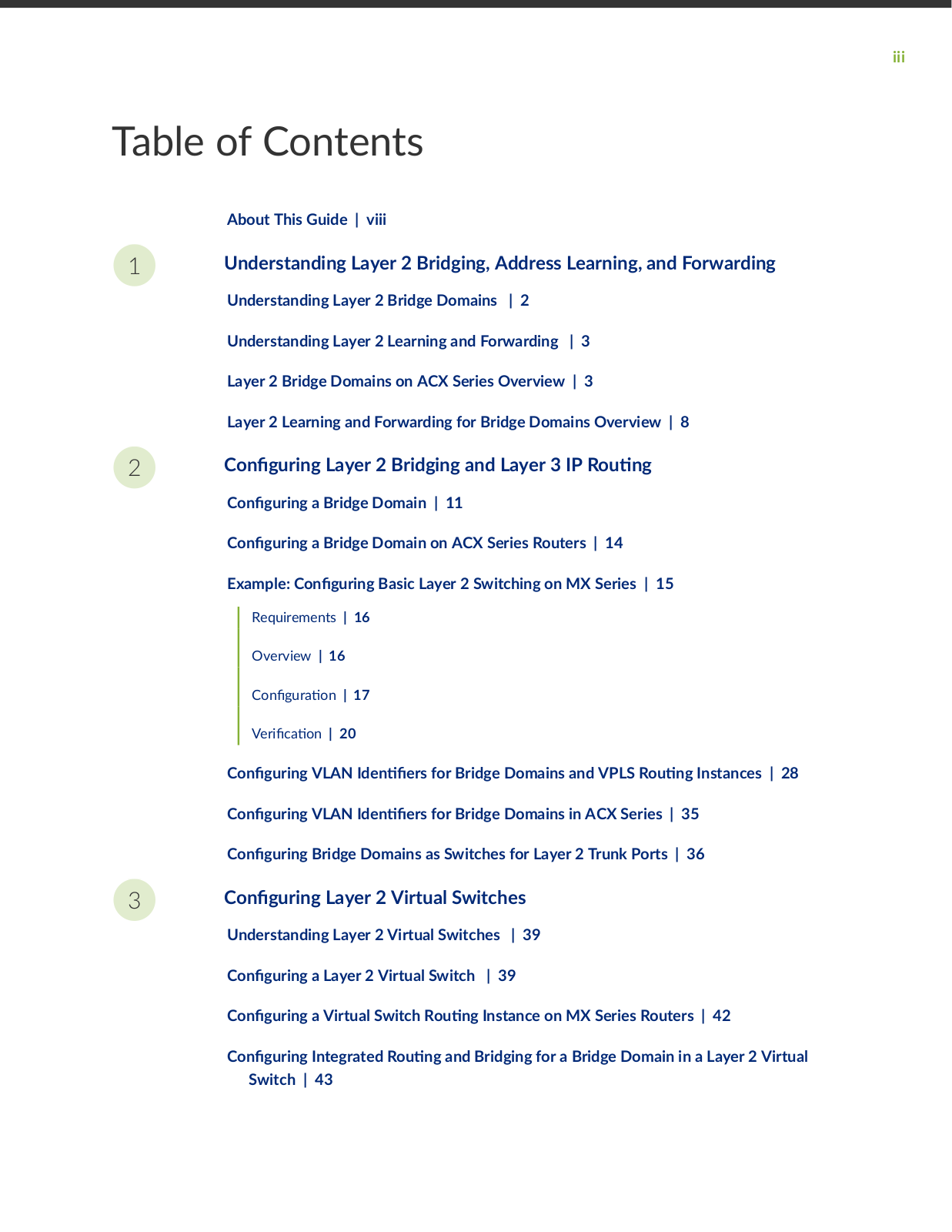
Table of Contents

About This Guide | viii

1Understanding Layer 2 Bridging, Address Learning, and Forwarding

Understanding Layer 2 Bridge Domains | 2

Understanding Layer 2 Learning and Forwarding | 3

Layer 2 Bridge Domains on ACX Series Overview | 3

Layer 2 Learning and Forwarding for Bridge Domains Overview | 8

2

n

r n

Layer 2 Bridging and Layer 3 IP R

n


n

r n

a Bridge Domain | 11


n

r n

a Bridge Domain on ACX Series Routers | 14


Example:

n r n

Basic Layer 2 Switching on MX Series | 15


Requirements | 16


Overview | 16


C n

r

n | 17


r

c

n | 20


n

r n

VLAN

n

rs for Bridge Domains and VPLS R

n Instances | 28


n

r n

VLAN

n

rs for Bridge Domains in ACX Series | 35


n

r n

Bridge Domains as Switches for Layer 2 Trunk Ports | 36

3

n

r n Layer 2 Virtual Switches


Understanding Layer 2 Virtual Switches | 39


n

r n

a Layer 2 Virtual Switch

| 39


n

r n

a Virtual Switch R

n

Instance on MX Series Routers | 42


n

r n

Integrated R n

and Bridging for a Bridge Domain in a Layer 2 Virtual

Switch | 43

4

5

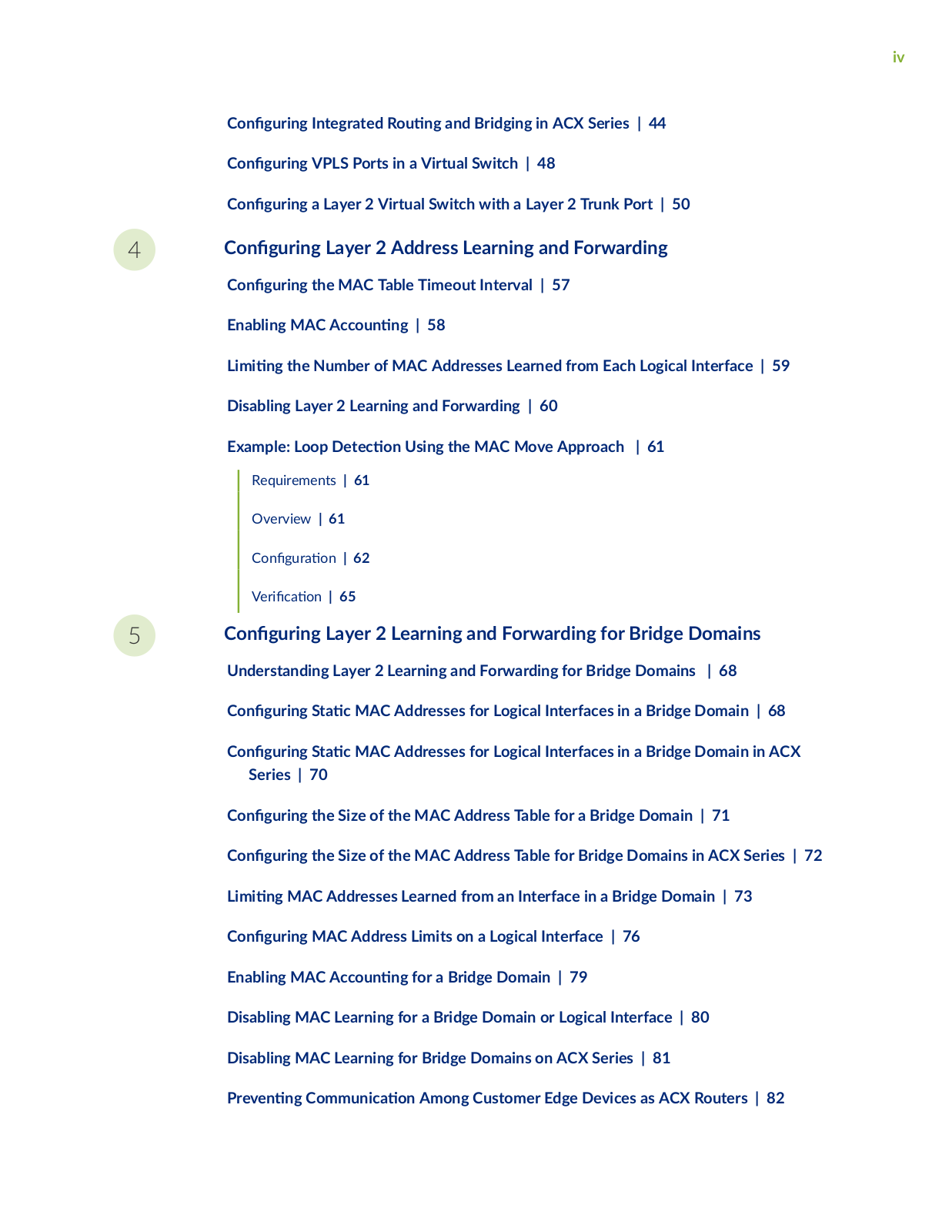
iv

n

r n

Integrated R

n and Bridging in ACX Series | 44

n

r n

VPLS Ports in a Virtual Switch | 48

n

r n

a Layer 2 Virtual Switch with a Layer 2 Trunk Port | 50

nr n Layer 2 Address Learning and Forwarding

nr n the MAC Table Timeout Interval | 57

Enabling MAC

cc n

n | 58


m n

the Number of MAC Addresses Learned from Each Logical Interface | 59

Disabling Layer 2 Learning and Forwarding | 60

Example: Loop

c

n Using the MAC Move Approach | 61


Requirements | 61


Overview | 61


C n

r

n | 62


r

c n | 65


nr n Layer 2 Learning and Forwarding for Bridge Domains

Understanding Layer 2 Learning and Forwarding for Bridge Domains | 68

n

r n

S

c MAC Addresses for Logical Interfaces in a Bridge Domain | 68

n

r n

S c MAC Addresses for Logical Interfaces in a Bridge Domain in ACX

Series | 70


n

r n

the Size of the MAC Address Table for a Bridge Domain | 71

n

r n

the Size of the MAC Address Table for Bridge Domains in ACX Series | 72

m n

MAC Addresses Learned from an Interface in a Bridge Domain | 73

n

r n

MAC Address Limits on a Logical Interface | 76

Enabling MAC

cc n n

for a Bridge Domain | 79

Disabling MAC Learning for a Bridge Domain or Logical Interface | 80

Disabling MAC Learning for Bridge Domains on ACX Series | 81

r v n

n

mm n c

n Among Customer Edge Devices as ACX Routers | 82

6

7

8

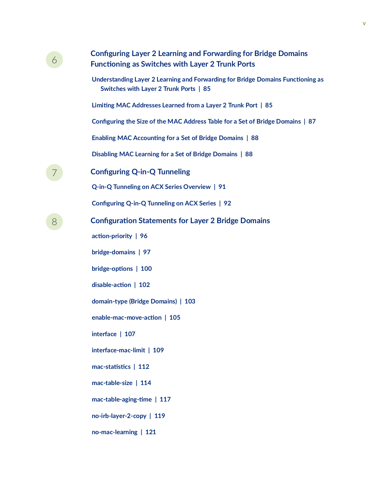
v

nr n Layer 2 Learning and Forwarding for Bridge Domains

nc n n as Switches with Layer 2 Trunk Ports

Understanding Layer 2 Learning and Forwarding for Bridge Domains nc n n as Switches with Layer 2 Trunk Ports | 85

m

n MAC Addresses Learned from a Layer 2 Trunk Port | 85

n

r n the Size of the MAC Address Table for a Set of Bridge Domains | 87

Enabling MAC cc n n for a Set of Bridge Domains | 88

Disabling MAC Learning for a Set of Bridge Domains | 88

nr n Q-in-Q Tunneling

Q-in-Q Tunneling on ACX Series Overview | 91 n r n Q-in-Q Tunneling on ACX Series | 92

nr n Statements for Layer 2 Bridge Domains

c n r r y | 96

bridge-domains | 97

br

ns | 100

s b

c n | 102

domain-type (Bridge Domains) | 103

n b

m c m v

c

n | 105

interface | 107


interface-mac-limit | 109

m c s

s

cs | 112


mac-table-size | 114


m c

b

n

m

| 117

no-irb-layer-2-copy | 119 no-mac-learning | 121

9

10

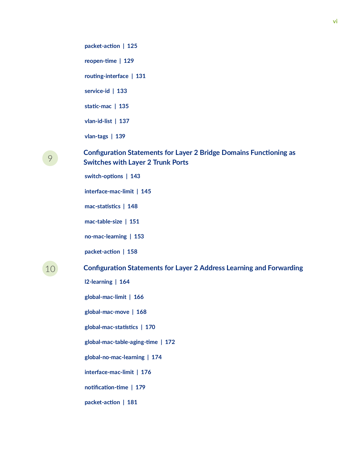
vi

cc n | 125

r

n

m

| 129

r

n

n

r c | 131

service-id | 133

s

c m c | 135

vlan-id-list | 137

vlan-tags | 139

n

r

n Statements for Layer 2 Bridge Domains nc n n as

Switches with Layer 2 Trunk Ports

sw c


ns | 143

interface-mac-limit | 145

m c s

s

cs | 148

mac-table-size | 151 no-mac-learning | 153

cc n | 158

nr n Statements for Layer 2 Address Learning and Forwarding

l2-learning | 164 global-mac-limit | 166 global-mac-move | 168

bm c s s cs | 170

b

m c

b

n m | 172

global-no-mac-learning | 174

interface-mac-limit | 176

n

c n

m

| 179

cc n | 181

11

12

13

vii

threshold-count | 185

r s m | 187

rn Mode Commands for Layer 2 Bridge Domains

clear bridge mac-table | 190

clear interfaces mac-database | 192

clear interfaces mac-database s s cs | 193 show bridge domain | 195

show bridge

| 198

show bridge mac-table | 208 show bridge s s cs | 216

rn Mode Commands for Layer 2 Learning

clear l2-learning m c m

v

b

r |

223

show l2-learning b

n

rm

n

| 224

show l2-learning global-mac-count | 227 show l2-learning instance | 229

show l2-learning interface | 231

show l2-learning m c m v b r | 234

Knowledge Base

viii

About This Guide

You can c

n

r one or more bridge domains to perform Layer 2 bridging. A bridge domain is a set of

logical interfaces that share the same

n or broadcast c r c

r s cs Layer 2 logical interfaces are

created by


n n one or more logical units on a physical interface with nc

s

n as ethernet-

bridge or vlan-bridge. All the member ports of the bridge domain

r c

in Layer 2 learning and

forwarding. Like a virtual LAN (VLAN), a bridge domain spans one or more ports of m

devices. You

can c n

r

Layer 2 MAC address and VLAN learning and forwarding r

r s in support of Layer 2

bridging.


Use this guide to c n r monitor, and troubleshoot Layer 2 bridging, address learning, and forwarding features on your Juniper Network devices.

Juniper Layer 2 Bridging User Manual

1

CHAPTER

Understanding Layer 2 Bridging,

Address Learning, and Forwarding

Understanding Layer 2 Bridge Domains | 2

Understanding Layer 2 Learning and Forwarding | 3

Layer 2 Bridge Domains on ACX Series Overview | 3

Layer 2 Learning and Forwarding for Bridge Domains Overview | 8

2

Understanding Layer 2 Bridge Domains

You can c

n

r one or more bridge domains on MX Series routers to perform Layer 2 bridging. The

Layer 2 bridging nc

ns of the MX Series routers include integrated r

n and bridging (IRB) for

support for Layer 2 bridging and Layer 3 IP r

n on the same interface, and virtual switches that

isolate a LAN segment with its spanning-tree protocol instance and separate its VLAN ID space.

A bridge domain is a set of logical ports that share the same


n or broadcast c

r c r s cs Like a

virtual LAN (VLAN), a bridge domain spans one or more ports of m

devices.


On Juniper Networks MX Series 5G Universal R

n


rms only, you can c n

r one or more

bridge domains to perform Layer 2 bridging. Thus, MX Series routers can

nc

n as Layer 2 switches,

each with m

bridging, or broadcast, domains that

r

c

in the same Layer 2 network. You can

also c

n

r

Layer 3 r

n support for a bridge domain. Integrated r

n

and bridging (IRB)

provides support for Layer 2 bridging and Layer 3 IP r

n

on the same interface. IRB enables you to

route packets to another routed interface or to another bridge domain that has a Layer 3 protocol

c n

r


You can also group one or more bridge domains within a single instance, or virtual switch. The MX Series

routers also support m

virtual switches, each of which operates independently of other virtual

switches on the router. Virtual switches isolate a LAN segment with its spanning-tree protocol

instance. . Thus, each virtual switch can r c

in a

r n Layer 2 network.

In Junos OS Release 9.2 and later, bridge domains provide support for a Layer 2 trunk port. A Layer 2

trunk interface enables you to c n

r a single logical interface to represent m

VLANs on a

physical interface. You can c n

r a set of bridge domains and VLAN n

rs that are

m c y

associated with one or more Layer 2 trunk interfaces. Packets received on a trunk interface are


forwarded within a bridge domain that has the same VLAN

n

r A Layer 2 trunk interface also

supports IRB within a bridge domain. In

n you can c

n

r Layer 2 learning and forwarding

r r s that apply to the n r

set of bridge domains.


In Junos OS Release 9.3 and later, you can c n

r VPLS ports in a virtual switch instead of a


dedicated r

n instance of type vpls so that the logical interfaces of the Layer 2 bridge domains in the

virtual switch can handle VPLS r

n instance r c Packets received on a Layer 2 trunk interface are

forwarded within a bridge domain that has the same VLAN

n

r


RELATED DOCUMENTATION

Understanding Layer 2 Virtual Switches | 39

Understanding Layer 2 Learning and Forwarding for Bridge Domains | 68

Understanding Layer 2 Learning and Forwarding for Bridge Domains F nc n n as Switches with Layer 2 Trunk Ports | 85

3

C n r n a Bridge Domain | 11

Understanding Layer 2 Learning and Forwarding

On MX Series routers only, you can c n r Layer 2 MAC address and VLAN learning and forwarding

rr s in support of Layer 2 bridging. The router learns unicast media access control (MAC)

addresses to avoid

n the packets to all the ports in a bridge domain. The MX Series router creates

a source MAC entry in its source and

s n

n MAC tables for each MAC address learned from


packets received on ports that belong to the bridge domain. If the bridge domain receives a control


protocol data unit (PDU) which does not have a corresponding protocol c n

r

then the control


PDU is considered as an unknown m

c s

data packet and the packets are


across all the ports

that are part of the same bridge domain. If the bridge domain has the protocol corresponding to the


PDU c n

r , then the control PDU is considered as a control packet and is processed by the r

n

engine.


By default, Layer 2 address learning is enabled. You can disable MAC learning for the router or for a


s c c bridge domain or logical interfaces. You can also c n

r the following Layer 2 forwarding


rr s for an MX Series router:

Timeout interval for MAC entries

• MAC cc n n

• A limit to the number of MAC addresses learned from the logical interfaces

RELATED DOCUMENTATION

Understanding Layer 2 Bridge Domains | 2

C n r n the MAC Table Timeout Interval | 57

Enabling MAC cc n n | 58

m n the Number of MAC Addresses Learned from Each Logical Interface | 59

Disabling Layer 2 Learning and Forwarding

Layer 2 Bridge Domains on ACX Series Overview

4

A bridge domain is a set of logical interfaces that share the same

n or broadcast c

r c

r s cs

Layer 2 logical interfaces are created by

n n

one or more logical units on a physical interface with

nc s

n as ethernet-bridge or vlan-bridge. All the member ports of the bridge domain

r c

in Layer 2 learning and forwarding. You can c n

r one or more bridge domains on ACX Series

routers to perform Layer 2 bridging. The Layer 2 bridging nc

ns of ACX Series routers include

integrated r

n and bridging (IRB) support for Layer 2 bridging and Layer 3 IP r

n

on the same

interface. IRB enables you to route packets to another routed interface or to another bridge domain that

has a Layer 3 protocol c n r


NOTE: ACX Series routers do not support the cr

n of bridge domains by using access and

trunk ports.


You can c n r E-LAN and E-LINE services by using bridge domains.

On ACX Series routers, you can c n

r bridge domains by using the following methods:

Bridge domain without a vlan-id number statement

Bridge domain with the vlan-id value set to none

Bridge domain with a single vlan-id

Bridge domain with a vlan-id-list

NOTE: The Layer 2 CLI c n r ns and show commands for ACX5048 and ACX5096 routers r compared to other ACX Series routers. For more n rm n see Layer 2 Next G n r n

Mode for ACX Series.

When you c n r E-LAN and E-LINE services using a bridge domain without a vlan-id number statement, the bridge domain should explicitly be normalized to a service VLAN ID and TPID by c n r n an input VLAN map under a logical interface. Explicit n rm z n is required when a

logical interface’s outer VLAN ID and TPID is not the same as the service VLAN ID and TPID of the service being c n r using a bridge domain.

The following input VLAN map nc ns are supported in ACX Series routers:

push—Add a new VLAN tag to the top of the VLAN stack.

swap—Replace the outer VLAN tag of the VLAN stack in a frame.

pop—Remove a VLAN tag from the top of the VLAN tag stack.

swap-swap—Replace both the outer and inner VLAN tags of the frame.

5

push-push—Push two VLAN tags on top of the VLAN stack.

NOTE: push-push does not work on ACX Series routers if the incoming packet already has a VLAN tag.

The following VLAN map nc ns are not supported in ACX Series routers:

swap-push—Replace the outer VLAN tag of the frame and add a new VLAN tag to the top of the VLAN stack.

pop-swap—Remove the outer VLAN tag of the frame and replace the inner VLAN tag of the frame.

pop-pop—Remove both the outer and inner VLAN tags of the frame.

NOTE: You can c n r Q-in-Q tunneling by explicitly c n r n an input VLAN map with the push nc n on the ingress logical interface.

A bridge domain can also be created by using aggregated Ethernet interfaces. Aggregated Ethernet interfaces are considered as logical interfaces in a bridge domain.

The following steps outline the process for bridging a packet received over a Layer 2 logical interface:

1.

When a packet is received on a physical port, it is accepted only if the VLAN

n r of the packet


matches the VLAN n

r of one of the logical interfaces c

n

r

on that port.

2.

If the bridge domain is c n

r

without a vlan-id number statement, then the VLAN tags are


r wr

n based on the input VLAN map c n r on the logical interface and normalized to a


service VLAN ID.


3.

If the bridge domain is c n

r

with a normalizing VLAN

n

r by using the vlan-id number


statement, the VLAN tags of the received packet are compared with the normalizing VLAN n r


If the VLAN tags of the packet are

r n from the normalizing VLAN

n

r the VLAN tags are


r wr

n as described in Table 1 on page 6.


4.

If the source MAC address of the received packet is not present in the source MAC table, it is learned


based on the normalizing VLAN

n r


5.

The packet is then forwarded toward one or more outbound Layer 2 logical interfaces based on the


s n

n MAC address. A packet with a known unicast s

n

n MAC address is forwarded only


to one outbound logical interface.


6

6. If the bridge domain is c

n

r without a vlan-id number statement, then for each outbound

Layer 2 logical interface, the VLAN tags are r wr

n based on the output VLAN map c n

r

on

that logical interface.


7. If the bridge domain is c

n

r with a normalizing VLAN

n

r by using the vlan-id number

statement, for each outbound Layer 2 logical interface, the normalizing VLAN

n r c

n

r

for the bridge domain is compared with the VLAN tags c n

r

on that logical interface. If the

VLAN tags associated with an outbound logical interface do not match the normalizing VLAN


n

r c

n r

for the bridge domain, the VLAN tags are r wr n as described in Table 2 on

page 7.


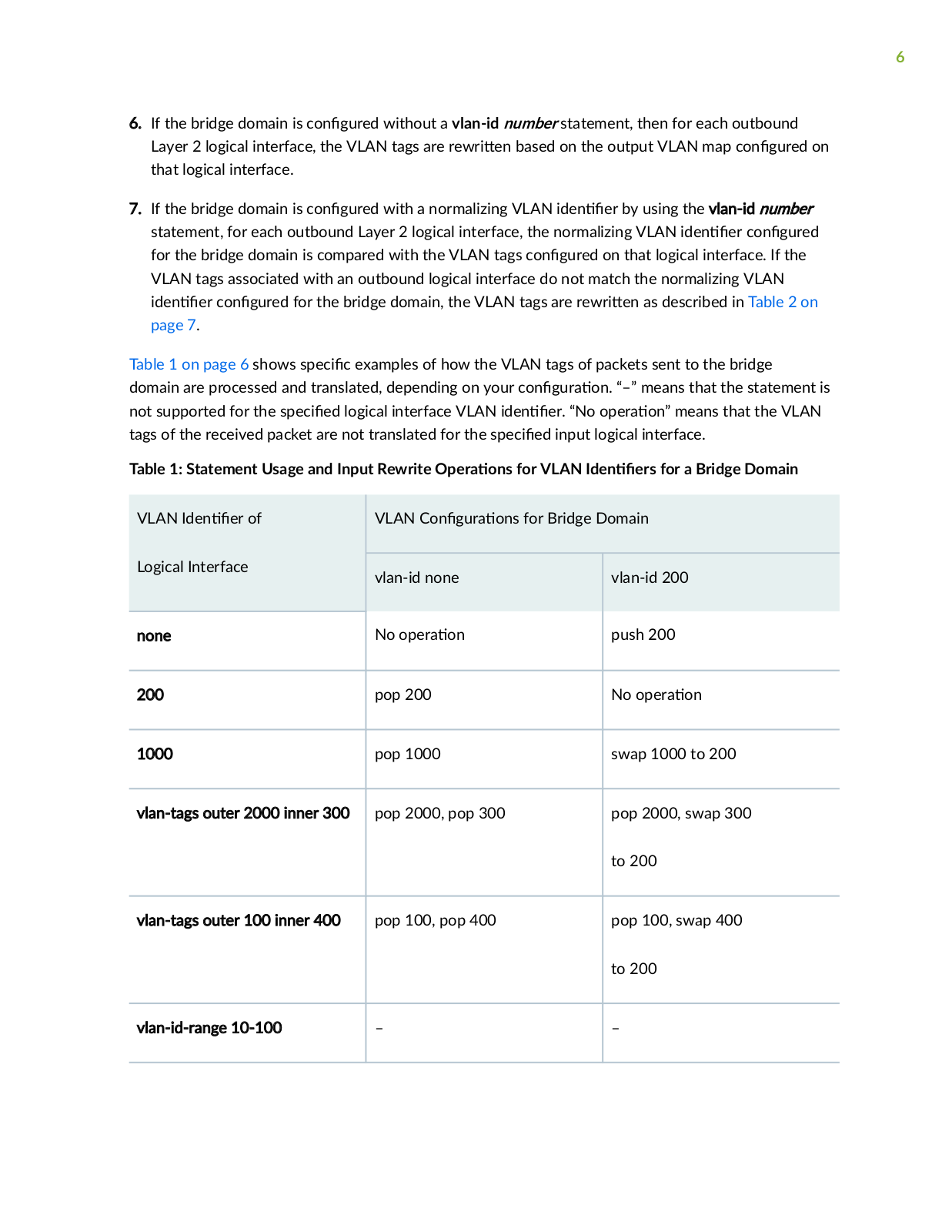
Table 1 on page 6 shows s

c

c examples of how the VLAN tags of packets sent to the bridge


domain are processed and translated, depending on your c n

r

n “–” means that the statement is

not supported for the s

c


logical interface VLAN

n

r “No

r

n means that the VLAN

tags of the received packet are not translated for the s

c

input logical interface.


Table 1: Statement Usage and Input Rewrite

r

ns for VLAN

n

rs for a Bridge Domain


VLAN

n

r of


VLAN C n

r

ns for Bridge Domain


Logical Interface


vlan-id none


vlan-id 200


none


No

r

n


push 200


200


pop 200


No

r

n


1000


pop 1000


swap 1000 to 200


vlan-tags outer 2000 inner 300

pop 2000, pop 300


pop 2000, swap 300


to 200


vlan-tags outer 100 inner 400


pop 100, pop 400


pop 100, swap 400


to 200


vlan-id-range 10-100


7

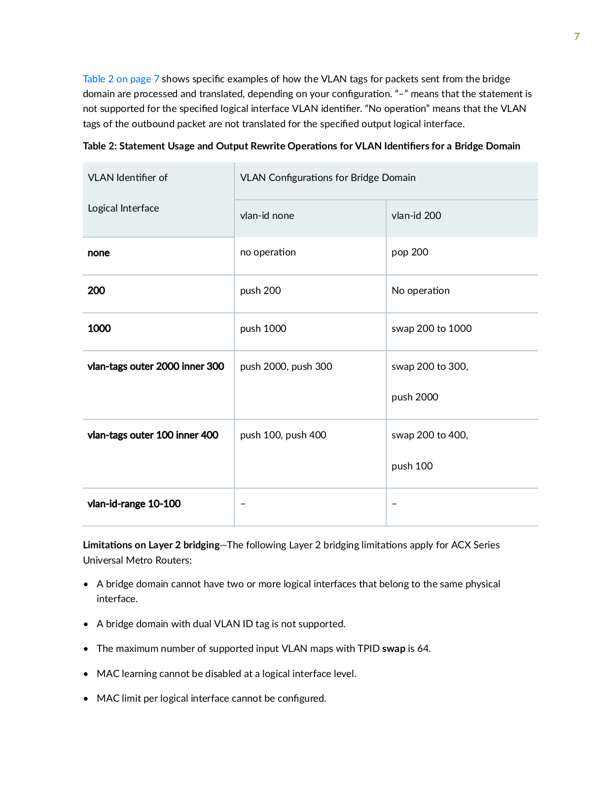
Table 2 on page 7 shows s c

c examples of how the VLAN tags for packets sent from the bridge

domain are processed and translated, depending on your c n

r

n “–” means that the statement is

not supported for the s c

logical interface VLAN

n

r “No

r

n means that the VLAN

tags of the outbound packet are not translated for the s

c

output logical interface.

Table 2: Statement Usage and Output Rewrite

r

ns for VLAN

n

rs for a Bridge Domain


VLAN

n r of


VLAN C n

r ns for Bridge Domain


Logical Interface


vlan-id none


vlan-id 200


none


no

r

n


pop 200


200


push 200


No

r n


1000


push 1000


swap 200 to 1000


vlan-tags outer 2000 inner 300

push 2000, push 300


swap 200 to 300,


push 2000


vlan-tags outer 100 inner 400


push 100, push 400


swap 200 to 400,


push 100


vlan-id-range 10-100


m

ns on Layer 2 bridging—The following Layer 2 bridging m

ns apply for ACX Series

Universal Metro Routers:


A bridge domain cannot have two or more logical interfaces that belong to the same physical interface.

A bridge domain with dual VLAN ID tag is not supported.

The maximum number of supported input VLAN maps with TPID swap is 64.

MAC learning cannot be disabled at a logical interface level.

• MAC limit per logical interface cannot be c n r

8

RELATED DOCUMENTATION

Q-in-Q Tunneling on ACX Series Overview | 91

Layer 2 Learning and Forwarding for Bridge Domains Overview | 8

C n

r n

a Bridge Domain on ACX Series Routers | 14

C n

r n

Q-in-Q Tunneling on ACX Series | 92


C n

r n

VLAN n rs for Bridge Domains in ACX Series | 35


Disabling MAC Learning for Bridge Domains on ACX Series | 81


C

n

r n

S c MAC Addresses for Logical Interfaces in a Bridge Domain in ACX Series | 70


C

n

r n

the Size of the MAC Address Table for Bridge Domains in ACX Series | 72

Layer 2 Learning and Forwarding for Bridge Domains Overview

When you c n

r a bridge domain, Layer 2 address learning is enabled by default. The bridge domain

learns unicast media access control (MAC) addresses to avoid

n the packets to all the ports in the

bridge domain. Each bridge domain creates a source MAC entry in its source and

s n

n MAC

tables for each source MAC address learned from packets received on the ports that belong to the

bridge domain.


NOTE:

r

c is not

back onto the interface on which it was received.


You can

n

y disable MAC learning either for the n r router or for a s c

c bridge domain. You

can also c

n

r the following Layer 2 learning and forwarding r

r s


S c MAC entries on logical interfaces

Size of the MAC address table for the bridge domain

RELATED DOCUMENTATION

Layer 2 Bridge Domains on ACX Series Overview | 3

Q-in-Q Tunneling on ACX Series Overview | 91

C n r n a Bridge Domain on ACX Series Routers | 14

C n r n Q-in-Q Tunneling on ACX Series | 92

9

C n

r n

VLAN n rs for Bridge Domains in ACX Series | 35

Disabling MAC Learning for Bridge Domains on ACX Series | 81


C

n

r n

S c MAC Addresses for Logical Interfaces in a Bridge Domain in ACX Series | 70


C

n

r n

the Size of the MAC Address Table for Bridge Domains in ACX Series | 72

2

CHAPTER

Layer 2 Bridging and

Layer 3 IP

C n

r n

a Bridge Domain | 11

C n

r n

a Bridge Domain on ACX Series Routers | 14

Example: C

n r n

Basic Layer 2 Switching on MX Series | 15

C n

r n

VLAN

n

rs for Bridge Domains and VPLS R n Instances |

28


C n

r n

VLAN

n

rs for Bridge Domains in ACX Series | 35

C n

r n

Bridge Domains as Switches for Layer 2 Trunk Ports | 36


11

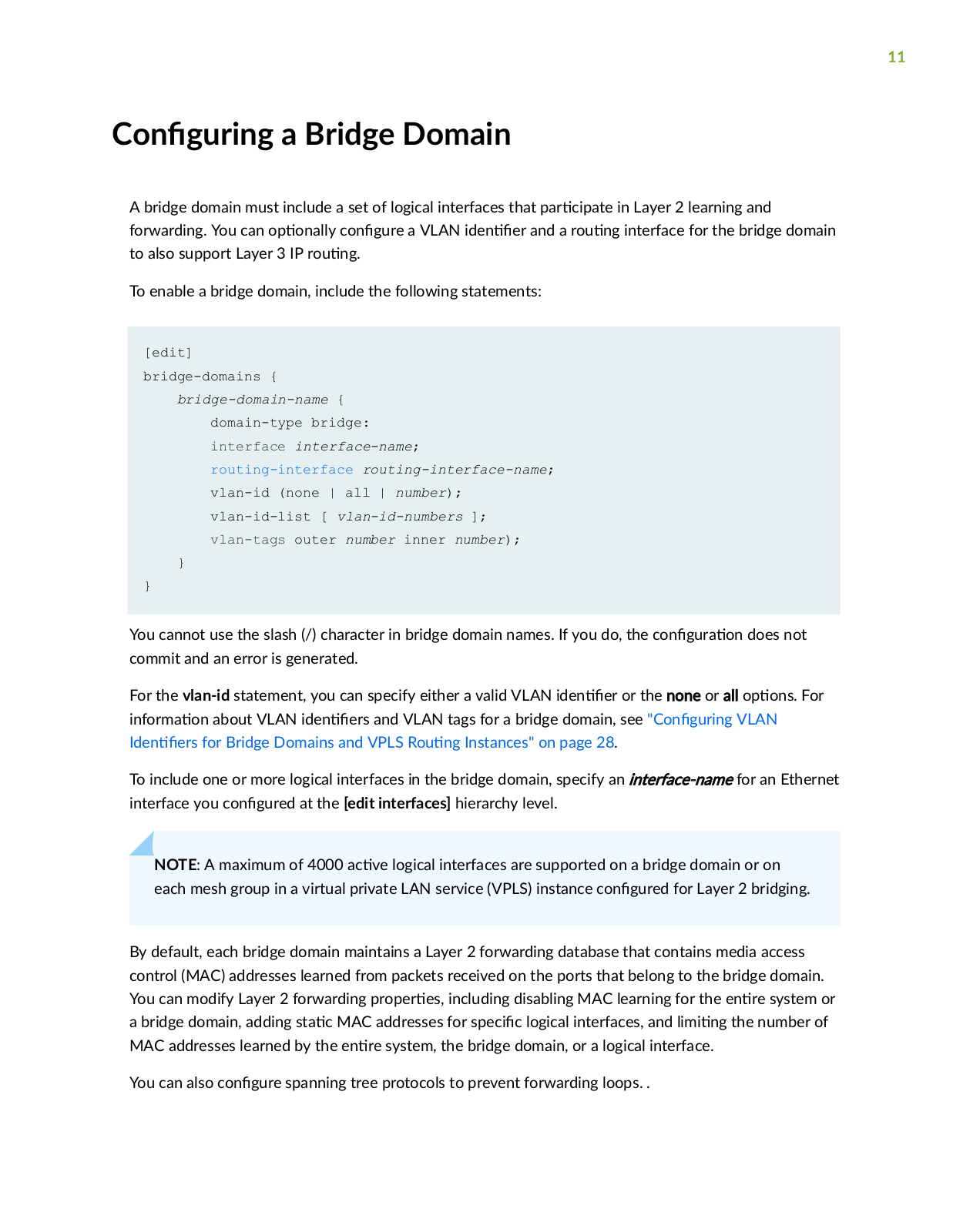
nr n a Bridge Domain

A bridge domain must include a set of logical interfaces that r c

in Layer 2 learning and

forwarding. You can

n

y c n

r a VLAN n

r and a r

n interface for the bridge domain

to also support Layer 3 IP r

n


To enable a bridge domain, include the following statements:

[edit] bridge-domains {

bridge-domain-name {

domain-type bridge: interface interface-name;

routing-interface routing-interface-name; vlan-id (none | all | number); vlan-id-list [ vlan-id-numbers ]; vlan-tags outer number inner number);

}

}


You cannot use the slash (/) character in bridge domain names. If you do, the c n

r

n does not

commit and an error is generated.


For the vlan-id statement, you can specify either a valid VLAN n

r or the none or all

ns For

n rm

n about VLAN n

rs and VLAN tags for a bridge domain, see C n

r n

VLAN


n

rs for Bridge Domains and VPLS R

n Instances" on page 28.


To include one or more logical interfaces in the bridge domain, specify an interface-name for an Ethernet interface you c n r at the [edit interfaces] hierarchy level.

NOTE: A maximum of 4000 c v logical interfaces are supported on a bridge domain or on each mesh group in a virtual private LAN service (VPLS) instance c n r for Layer 2 bridging.

By default, each bridge domain maintains a Layer 2 forwarding database that contains media access control (MAC) addresses learned from packets received on the ports that belong to the bridge domain.

You can modify Layer 2 forwarding

r

r s including disabling MAC learning for the

n r system or

a bridge domain, adding s c MAC addresses for s c c logical interfaces, and m n

the number of

MAC addresses learned by the n

r

system, the bridge domain, or a logical interface.


You can also c n

r spanning tree protocols to prevent forwarding loops. .


12

In Junos OS Release 8.5 and later, you can c n r IGMP snooping for a bridge domain. For more

n rm

n see the Junos OS M c s Protocols User Guide.

Integrated r

n and bridging (IRB) provides simultaneous support for Layer 2 bridging and Layer 3

rn on the same interface. IRB enables you to route packets to another routed interface or to

another bridge domain that has an IRB interface c n r You c n r a logical r n interface by including the irb statement at the [edit interfaces] hierarchy level and include that interface in the bridge


domain. For more n

rm

n about how to c n

r a r

n

interface, see the Junos OS Network


Interfaces Library for R

n

Devices.


NOTE: You can include only one r

n

interface in a bridge domain.


To c n

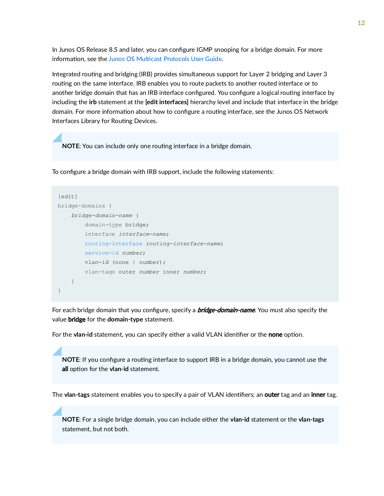
r a bridge domain with IRB support, include the following statements:


[edit]


bridge-domains {


bridge-domain-name {


domain-type bridge;


interface interface-name;


routing-interface routing-interface-name;


service-id number;


vlan-id (none | number);


vlan-tags outer number inner number;


}

}


For each bridge domain that you c n

r

specify a bridge-domain-name. You must also specify the


value bridge for the domain-type statement.


For the vlan-id statement, you can specify either a valid VLAN

n

r or the none

n


NOTE: If you c n

r

a r

n interface to support IRB in a bridge domain, you cannot use the


all

n for the vlan-id statement.


The vlan-tags statement enables you to specify a pair of VLAN

n

rs an outer tag and an inner tag.

NOTE: For a single bridge domain, you can include either the vlan-id statement or the vlan-tags statement, but not both.

13

For MC-LAG bridge domains, when the VLAN

n

r is none, use the service-id statement to

facilitate media access control (MAC) and Address R s

n Protocol (ARP) sync r n z

n among

MC-LAG peers.


To include one or more logical interfaces in the bridge domain, specify the interface name for each

Ethernet interface to include that you c

n

r

at the [edit interfaces] hierarchy level.


NOTE: A maximum of 4000

c v

logical interfaces are supported on a bridge domain or on


each mesh group in a VPLS r

n

instance c

n

r for Layer 2 bridging.


To associate a r

n interface with a bridge domain, include the r

n

n

r c r

n n r c

n m statement and specify a r

n

n

r

c n m

you c n

r

at the [edit interfaces irb]

hierarchy level. You can c n

r

only one r

n

interface for each bridge domain. For more

n

rm

n about how to c

n

r logical and r

n

interfaces, see the Junos OS Network Interfaces

Library for R

n Devices.


In Junos OS Release 9.0 and later, IRB interfaces are supported for m


c s

snooping. For more

n

rm

n about m c s

snooping, see the Understanding M

c s

Snooping and VPLS Root

rc n.

In Junos 11.4 and later, IP m c s is supported on Layer 2 trunk ports through IRB interfaces using the Trio chipset.

In Junos OS Release 9.6 and later, in m

m

VPLS c n

r

ns you can c

n


r VPLS to keep a

VPLS c

nn

c

n up if only an IRB interface is available by c

n

r n

the irb


n for the

c nn c

v

y

y statement at the [edit r

n

ns

nc s r

n

ns

nc

n m

protocols vpls]

hierarchy level. The c nn c

v y y statement has two

ns ce and irb. The ce

n is the

default and s

c s that a CE interface is required to maintain the VPLS c

nn c


n By default, if only

an IRB interface is available, the VPLS c nn c

n is brought down. For more n

rm

n about

c n

r n

VPNs, see the Junos VPN C n

r

n Guide.


NOTE: When you c n

r IRB interfaces in more than one logical system on a device, all of the

of the IRB logical interfaces share the same MAC address.


Integrated Bridging and R

n (IRB) interfaces are used to

together Layer 2 switched and Layer 3

routed domains on MX routers. MX routers support c

ss

rs and rewrite rules on the IRB interface at

the [edit class-of-service interfaces irb unit logical-unit-number] level of the hierarchy. All types of

c ss

rs and rewrite rules are allowed, including IEEE 802.1p.


14

NOTE: The IRB c ss rs and rewrite rules are used only for routed packets; in other words, it is for r c that originated in the Layer 2 domain and is then routed through IRB into the Layer 3 domain, or vice versa. Only IEEE c ss rs and IEEE rewrite rules are allowed for pure Layer 2 interfaces within a bridge domain.

RELATED DOCUMENTATION

Understanding Layer 2 Learning and Forwarding | 3

Understanding Layer 2 Learning and Forwarding for Bridge Domains | 68

Understanding Layer 2 Learning and Forwarding for Bridge Domains F nc n n as Switches with Layer 2 Trunk Ports | 85

nr n a Bridge Domain on ACX Series Routers

A bridge domain must include a set of logical interfaces that r c

in Layer 2 learning and

forwarding.


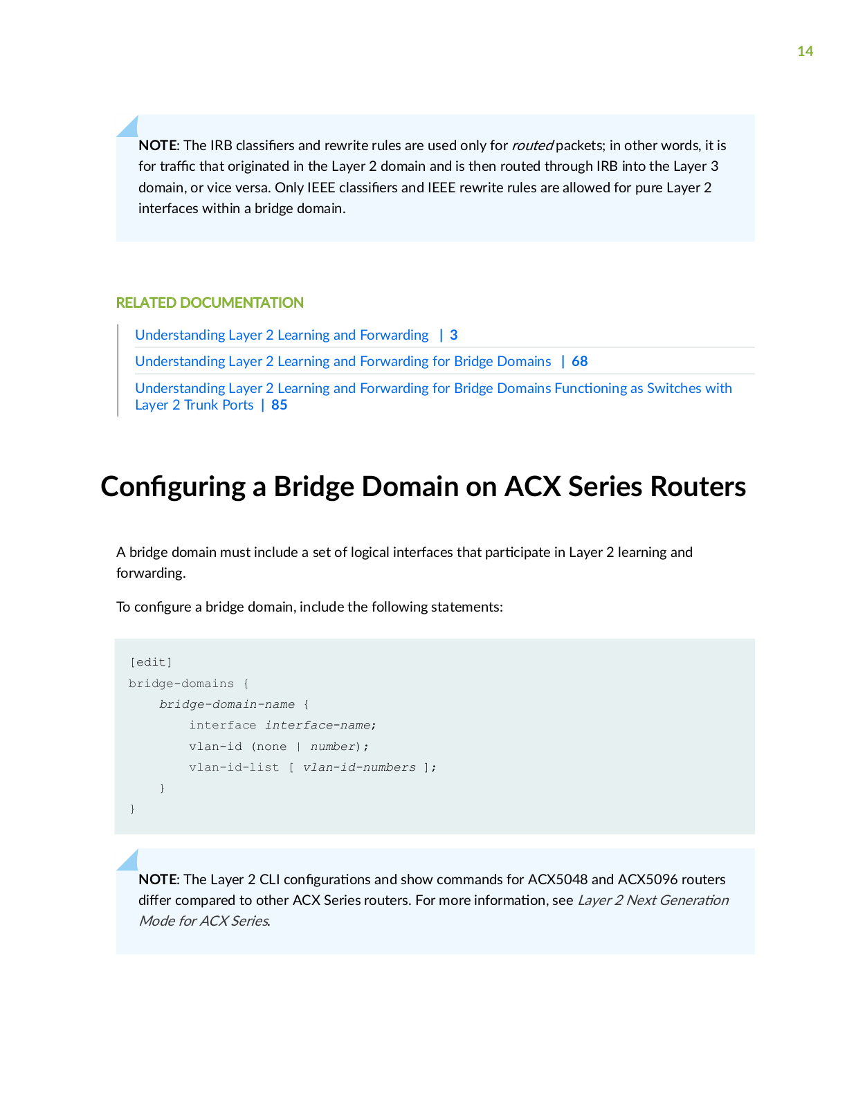
To c n

r a bridge domain, include the following statements:


[edit] bridge-domains {

bridge-domain-name { interface interface-name; vlan-id (none | number);

vlan-id-list [ vlan-id-numbers ];

}

}

NOTE: The Layer 2 CLI c n r ns and show commands for ACX5048 and ACX5096 routers r compared to other ACX Series routers. For more n rm n see Layer 2 Next G n r n

Mode for ACX Series.

15

You cannot use the slash (/) character in bridge domain names. If you do, the c n

r

n does not

commit and an error is generated.


For the vlan-id statement, you can specify either a valid VLAN n

r or none.


To include one or more logical interfaces in the bridge domain, specify an interface name for an Ethernet interface you c n r at the [edit bridge-domains bridge-domain-name] hierarchy level.

To c

n

r a layer 2 logical interface to be included in a bridge domain, you can either include the

nc

s

n vlan-bridge statement under the logical interface, or the nc s

n ethernet-bridge

statement under the physical interface.


NOTE: A maximum of 1000 logical interfaces can be c n r on a physical interface. You can

c n

r a maximum of 3000 bridge domains on an ACX Series router.


RELATED DOCUMENTATION

Layer 2 Bridge Domains on ACX Series Overview | 3

Q-in-Q Tunneling on ACX Series Overview | 91

Layer 2 Learning and Forwarding for Bridge Domains Overview | 8

C n

r n

Q-in-Q Tunneling on ACX Series | 92


C n

r n

VLAN n rs for Bridge Domains in ACX Series | 35


Disabling MAC Learning for Bridge Domains on ACX Series | 81


C

n

r n

S c MAC Addresses for Logical Interfaces in a Bridge Domain in ACX Series | 70


C

n

r n

the Size of the MAC Address Table for Bridge Domains in ACX Series | 72

Example: n r n Basic Layer 2 Switching on MX Series

IN THIS SECTION

Requirements | 16

Overview | 16

16


C n

r

n | 17


r

c

n | 20


This example shows how to c n r Layer 2 switching with all interfaces r c

n in a single

VLAN.


Requirements

No special c n r n beyond device n

z

n is required before c n r n this example.

This example uses an MX Series device to perform Layer 2 switching.

Overview

IN THIS SECTION

Topology | 17

In this example, a single MX Series device is c n

r to act as a basic single-VLAN switch. Three

c nn c ns are in place. The c

nn c ns from the MX Series device

c to Junos OS routers, but

the routers are used here for

s n purposes only. In place of routers, you can use any IP networking

devices.


17

Topology

Figure 1 on page 17 shows the sample network.

Figure 1: Basic Layer 2 Switching

"CLI Quick C n r n on page 17 shows the c n r n for all of the devices in Figure 1 on page 17.

The s c n "No Link Title" on page 19 describes the steps on Device S1.

n r n

IN THIS SECTION

CLI Quick C n r n | 17

Procedure | 19

CLI Quick n r

n

To quickly c n r this example, copy the following commands, paste them into a text

remove any

line breaks, change any details necessary to match your network c n r

n and then copy and paste

the commands into the CLI at the [edit] hierarchy level.


18

Device S1

set interfaces ge-2/0/0 vlan-tagging


set interfaces ge-2/0/0

nc

s

n extended-vlan-bridge

set interfaces ge-2/0/0 unit 0 vlan-id 600

set interfaces ge-2/0/1 vlan-tagging


set interfaces ge-2/0/1

nc

s

n extended-vlan-bridge

set interfaces ge-2/0/1 unit 0 vlan-id 600

set interfaces ge-2/0/2 vlan-tagging


set interfaces ge-2/0/2

nc

s

n extended-vlan-bridge

set interfaces ge-2/0/2 unit 0 vlan-id 600

set bridge-domains customer1 domain-type bridge set bridge-domains customer1 interface ge-2/0/0.0 set bridge-domains customer1 interface ge-2/0/2.0 set bridge-domains customer1 interface ge-2/0/1.0

Device R1

set interfaces ge-1/3/2 vlan-tagging

set interfaces ge-1/3/2 unit 0 vlan-id 600

set interfaces ge-1/3/2 unit 0 family inet address 10.0.0.1/24

Device R2

set interfaces ge-3/1/0 vlan-tagging

set interfaces ge-3/1/0 unit 0 vlan-id 600

set interfaces ge-3/1/0 unit 0 family inet address 10.0.0.2/24

Device R3

set interfaces ge-2/0/1 vlan-tagging

set interfaces ge-2/0/1 unit 0 vlan-id 600

set interfaces ge-2/0/1 unit 0 family inet address 10.0.0.3/24

19

Procedure

Step-by-Step Procedure

The following example requires that you navigate various levels in the c

n

r

n hierarchy. For

n

rm

n about n v

n the CLI, see Using the CLI Editor in C n

r

n Mode in the Junos OS

CLI User Guide.


To c

n

r

Device S1:


1.

C

n

r

the device interfaces.


[edit interfaces]


user@S1# set interfaces ge-2/0/0 vlan-tagging


user@S1# set interfaces ge-2/0/0 nc

s

n extended-vlan-bridge


user@S1# set interfaces ge-2/0/0 unit 0 vlan-id 600


user@S1# set interfaces ge-2/0/1 vlan-tagging


user@S1# set interfaces ge-2/0/1 nc

s

n extended-vlan-bridge


user@S1# set interfaces ge-2/0/1 unit 0 vlan-id 600


user@S1# set interfaces ge-2/0/2 vlan-tagging


user@S1# set interfaces ge-2/0/2 nc

s

n extended-vlan-bridge


user@S1# set interfaces ge-2/0/2 unit 0 vlan-id 600

2. C n r the bridge domain.

[edit interfaces]

user@S1# set bridge-domains customer1 domain-type bridge user@S1# set bridge-domains customer1 interface ge-2/0/0.0 user@S1# set bridge-domains customer1 interface ge-2/0/2.0 user@S1# set bridge-domains customer1 interface ge-2/0/1.0

Results

From c n r n mode, c n rm your c n r n by entering the domains commands. If the output does not display the intended c n this example to correct the c n r n

show interfaces and show bridge- r n repeat the ns r c ns in

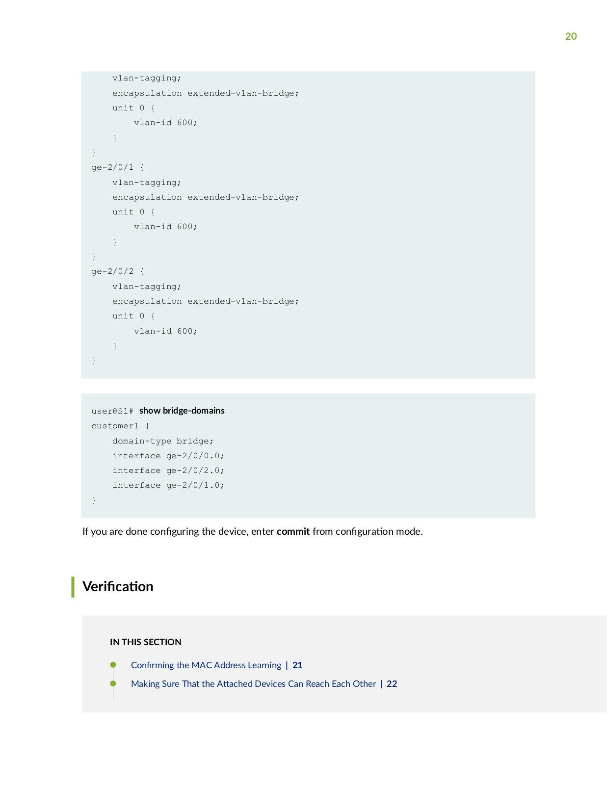
user@S1# show interfaces

ge-2/0/0 {

20

vlan-tagging;

encapsulation extended-vlan-bridge; unit 0 {

vlan-id 600;

}

}

ge-2/0/1 { vlan-tagging;

encapsulation extended-vlan-bridge; unit 0 {

vlan-id 600;

}

}

ge-2/0/2 { vlan-tagging;

encapsulation extended-vlan-bridge; unit 0 {

vlan-id 600;

}

}

user@S1# show bridge-domains customer1 {

domain-type bridge; interface ge-2/0/0.0; interface ge-2/0/2.0; interface ge-2/0/1.0;

}

If you are done c n r n the device, enter commit from c n r n mode.

r c n

IN THIS SECTION

C n rm n the MAC Address Learning | 21

Making Sure That the

c

Devices Can Reach Each Other | 22

21

Checking the Bridge Domain | 23

Checking the Bridge S s cs | 24

Checking the Bridge Flooding | 25

Checking Layer 2 Learning | 27

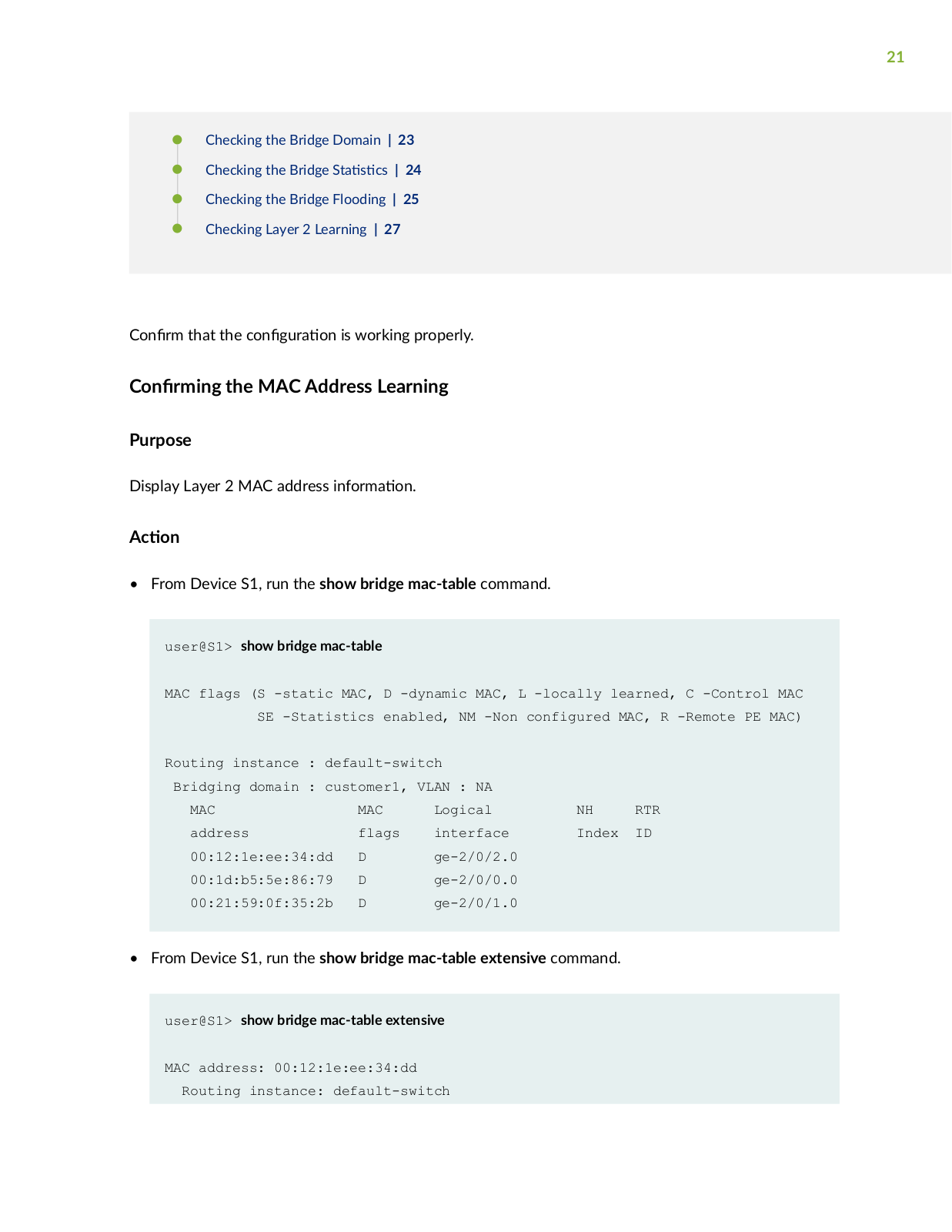
C n rm that the c n r n is working properly.

n rm n the MAC Address Learning

Purpose

Display Layer 2 MAC address n rm n

cn

From Device S1, run the show bridge mac-table command.

user@S1> show bridge mac-table

MAC flags (S -static MAC, D -dynamic MAC, L -locally learned, C -Control MAC SE -Statistics enabled, NM -Non configured MAC, R -Remote PE MAC)

Routing instance : default-switch


Bridging domain : customer1, VLAN : NA


MAC

MAC

Logical

NH

RTR

address

flags

interface

Index

ID

00:12:1e:ee:34:dd

D

ge-2/0/2.0


00:1d:b5:5e:86:79

D

ge-2/0/0.0


00:21:59:0f:35:2b

D

ge-2/0/1.0


• From Device S1, run the show bridge mac-table extensive command.

user@S1> show bridge mac-table extensive

MAC address: 00:12:1e:ee:34:dd

Routing instance: default-switch

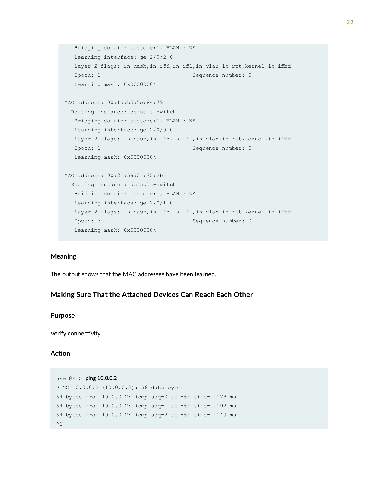
22

Bridging domain: customer1, VLAN : NA

Learning interface: ge-2/0/2.0

Layer 2 flags: in_hash,in_ifd,in_ifl,in_vlan,in_rtt,kernel,in_ifbd

Epoch: 1 Sequence number: 0

Learning mask: 0x00000004

MAC address: 00:1d:b5:5e:86:79

Routing instance: default-switch

Bridging domain: customer1, VLAN : NA

Learning interface: ge-2/0/0.0

Layer 2 flags: in_hash,in_ifd,in_ifl,in_vlan,in_rtt,kernel,in_ifbd

Epoch: 1 Sequence number: 0

Learning mask: 0x00000004

MAC address: 00:21:59:0f:35:2b

Routing instance: default-switch

Bridging domain: customer1, VLAN : NA

Learning interface: ge-2/0/1.0

Layer 2 flags: in_hash,in_ifd,in_ifl,in_vlan,in_rtt,kernel,in_ifbd

Epoch: 3 Sequence number: 0

Learning mask: 0x00000004

Meaning

The output shows that the MAC addresses have been learned.

Making Sure That the

c

Devices Can Reach Each Other

Purpose

Verify c nn c v y

cn

user@R1> ping 10.0.0.2

PING 10.0.0.2 (10.0.0.2): 56 data bytes

64 bytes from 10.0.0.2: icmp_seq=0 ttl=64 time=1.178 ms 64 bytes from 10.0.0.2: icmp_seq=1 ttl=64 time=1.192 ms 64 bytes from 10.0.0.2: icmp_seq=2 ttl=64 time=1.149 ms ^C

Loading...
+ 216 hidden pages