

Page 1

J-Web Application Package for EX Series
Published
2021-03-02
Ethernet Switches
J-Web Application Package User Guide for
EX Series Switches
Page 2

Juniper Networks, Inc.
1133 Innovation Way
Sunnyvale, California 94089
USA
408-745-2000
www.juniper.net
Juniper Networks, the Juniper Networks logo, Juniper, and Junos are registered trademarks of Juniper Networks, Inc. in
the United States and other countries. All other trademarks, service marks, registered marks, or registered service marks
are the property of their respective owners.
Juniper Networks assumes no responsibility for any inaccuracies in this document. Juniper Networks reserves the right
to change, modify, transfer, or otherwise revise this publication without notice.
J-Web Application Package for EX Series Ethernet Switches J-Web Application Package User Guide for EX Series Switches
Copyright © 2021 Juniper Networks, Inc. All rights reserved.
The information in this document is current as of the date on the title page.
ii
YEAR 2000 NOTICE
Juniper Networks hardware and software products are Year 2000 compliant. Junos OS has no known time-related
limitations through the year 2038. However, the NTP application is known to have some difficulty in the year 2036.
END USER LICENSE AGREEMENT
The Juniper Networks product that is the subject of this technical documentation consists of (or is intended for use with)
Juniper Networks software. Use of such software is subject to the terms and conditions of the End User License Agreement
(“EULA”) posted at https://support.juniper.net/support/eula/. By downloading, installing or using such software, you
agree to the terms and conditions of that EULA.
Page 3

Table of Contents
1
About the Documentation | x
Documentation and Release Notes | x
Using the Examples in This Manual | x
Merging a Full Example | xi
Merging a Snippet | xii
Documentation Conventions | xii
Documentation Feedback | xv
Requesting Technical Support | xv
Self-Help Online Tools and Resources | xvi
Creating a Service Request with JTAC | xvi
iii
Overview
Overview | 2
J-Web User Interface for EX Series Switches Overview | 2
J-Web Packages | 2
Release Compatibility | 4
Software Requirements | 5
J-Web Interface—Application Package | 6
J-Web Application Package—First Look | 6
Understanding J-Web User Interface Sessions | 9
Dashboard for EX Series Switches | 10
Graphical Chassis Viewer | 11
System Information Panel | 13
Health Status Panel | 16
Capacity Utilization Panel | 20
Alarms Panel | 20
File System Usage | 21
Chassis Viewer | 21
Understanding J-Web Configuration Tools | 37
Understand Alarm Types and Severity Levels on EX Series Switches | 39
Using the Commit Options to Commit Configuration Changes (J-Web Procedure) | 40
Page 4

Configuration
2
Starting J-Web | 45
Starting the J-Web Interface | 45
J-Web Configuration Tools | 47
Using the Point and Click CLI Tool in the J-Web Interface to Edit Configuration Text | 47
Using the CLI Editor in the J-Web Interface to Edit Configuration Text | 49
Using the J-Web CLI Terminal | 50
Configuring the Web Browser | 50
Setting Domain Name, Hostname, and Name Server | 51
Enabling SSH on your system | 51
Sample Configuration on an EX Series Switch | 52
Using the CLI Viewer in the J-Web Interface to View Configuration Text | 53
iv
System Basics Configuration | 54
Connecting and Configuring an EX Series Switch (J-Web Procedure) | 54
Configuring Date and Time for the EX Series Switch (J-Web Procedure) | 59
Configuring System Identity for an EX Series Switch (J-Web Procedure) | 60
Configuring Management Access for the EX Series Switch (J-Web Procedure) | 61
Generating SSL Certificates to Be Used for Secure Web Access (EX Series Switch) | 66
Rebooting or Halting the EX Series Switch (J-Web Procedure) | 67
Class of Service Configuration | 68
Defining CoS Drop Profiles (J-Web Procedure) | 68
Defining CoS Classifiers (J-Web Procedure) | 70
Defining CoS Code-Point Aliases (J-Web Procedure) | 72
Assigning CoS Components to Interfaces (J-Web Procedure) | 73
Defining CoS Forwarding Classes (J-Web Procedure) | 75
Defining CoS Rewrite Rules (J-Web Procedure) | 78
Defining CoS Schedulers (J-Web Procedure) | 80
Defining CoS Scheduler Maps (J-Web Procedure) | 83
Page 5

Security and Management Configuration | 85
Configuring 802.1X Authentication (J-Web Procedure) | 85
Configuring LLDP (J-Web Procedure) | 88
Configuring Port Mirroring to Analyze Traffic (J-Web Procedure) | 90
Configuring Port Security (J-Web Procedure) | 93
Routing Policies and Packet Filtering Configuration | 98
Configuring Routing Policies (J-Web Procedure) | 98
Configuring Firewall Filters (J-Web Procedure) | 105
Ethernet Switching Configuration | 112
Configuring VLANs for EX Series Switches (J-Web Procedure) | 112
Configuring Spanning Tree Protocols on EX Series Switches (J-Web Procedure) | 115
Configuring IGMP Snooping on EX Series Switches (J-Web Procedure) | 121
v
Configuring Redundant Trunk Groups on EX Series Switches (J-Web Procedure) | 124
Interfaces | 126
Configuring Gigabit Ethernet Interfaces (J-Web Procedure) | 126
Configuring Aggregated Ethernet Interfaces (J-Web Procedure) | 134
Configuring PoE (J-Web Procedure) | 139
Configuring PoE on EX2200, EX2200-C, EX3200, EX3300, EX4200, and EX4300 Switches | 139
Configuring PoE on EX6200 Switches | 141
Configuring Services | 143
Configuring DHCP Services (J-Web Procedure) | 143
Configuring DHCP Services (J-Web Procedure) on EX Series Switches | 143
Configuring DHCP Services on EX4300 Switches (J-Web Procedure) | 147
Configuring SNMP (J-Web Procedure) | 153
Configuring Layer 3 Protocols | 158
Configuring BGP Sessions (J-Web Procedure) | 158
Configuring an OSPF Network (J-Web Procedure) | 164
Configuring a RIP Network for EX Series Switches (J-Web Procedure) | 171
Configuring Static Routing (J-Web Procedure) | 175
Page 6

Configuring Real-Time Performance Monitoring | 178
Configuring Real-Time Performance Monitoring (J-Web Procedure) | 178
Viewing Real-Time Performance Monitoring Information | 186
Software Installation and Upgrades | 187
Updating J-Web Interface on EX Series Switches (J-Web Procedure) | 187
Installing J-Web Application Package by Using Auto Update | 187
Installing J-Web Application Package by Using Manual Update | 188
Upgrading Junos OS on EX Series Switches (J-Web Procedure) | 189
Installing Junos OS Upgrades from a Remote Server | 190
Installing Junos OS Upgrades by Uploading File from Local Computer | 191
Configuration, Files, Users, Licenses, and Product Registration | 192
Managing Configuration Files Through the Configuration History (J-Web Procedure) | 192
vi
Displaying Configuration History | 193
Displaying Users Editing the Configuration | 194
Comparing Configuration Files with the J-Web Interface | 194
Downloading a Configuration File with the J-Web Interface | 195
Loading a Previous Configuration File with the J-Web Interface | 195
Setting or Deleting the Rescue Configuration (J-Web Procedure) | 196
Uploading a Configuration File (J-Web Procedure) | 196
Managing Log, Temporary, and Crash Files on the Switch (J-Web Procedure) | 197
Cleaning Up Files | 197
Downloading Files | 198
Deleting Files | 199
Managing Users (J-Web Procedure) | 200
Managing Licenses for the EX Series Switch (J-Web Procedure) | 202
Adding New Licenses | 203
Deleting Licenses | 203
Displaying License Keys | 204
Downloading Licenses | 204
Registering the EX Series Switch with the J-Web Interface | 204
Generating Support Information Reports for EX Series Switches Using the J-Web Interface | 205
Page 7

Virtual Chassis Configuration | 206
3
Configuring a Virtual Chassis on an EX Series Switch (J-Web Procedure) | 206
Configuring an EX2200, EX2200-C, EX3300, EX4200, EX4300, EX4500, EX4550, or EX4600
Virtual Chassis (J-Web Procedure) | 206
Enabling Virtual Chassis Mode on an EX8200 Switch (J-Web Procedure) | 208
Configuring an EX8200 Virtual Chassis (J-Web Procedure) | 209
Preprovision the Virtual Chassis | 209
Configure Virtual Chassis Members | 209
Configure Virtual Chassis Ports | 210
Monitoring
Monitoring Tasks | 213
Check Active Alarms with the J-Web Interface | 214
Monitor System Log Messages | 215
vii
Monitoring Chassis Information | 220
Monitoring System Properties | 223
Monitoring System Process Information | 225
Monitoring Switch Control Traffic | 226
Monitoring Interface Status and Traffic | 229
Monitoring PoE | 231
Monitoring Hosts Using the J-Web Ping Host Tool | 232
Monitoring Network Traffic Using Traceroute | 235
Monitoring DHCP Services | 237
Monitoring OSPF Routing Information | 243
Monitoring RIP Routing Information | 246
Monitoring BGP Routing Information | 248
Monitoring Routing Information | 250
Monitoring Ethernet Switching on EX Series Switches (J-Web) | 253
Monitoring IGMP Snooping | 256
Monitoring Spanning Tree Protocols on Switches | 259
Monitoring CoS Classifiers | 261
Monitoring CoS Drop Profiles | 263
Monitoring CoS Value Aliases | 264
Monitoring CoS Forwarding Classes | 266
Page 8

Monitoring Interfaces That Have CoS Components | 268
4
Monitoring CoS Rewrite Rules | 270
Monitoring CoS Scheduler Maps | 271
Monitoring the Virtual Chassis Status and Statistics on EX Series Virtual Chassis | 274
Monitoring 802.1X Authentication | 276
Monitoring Port Security | 277
Administration
Software, Files, Licenses, Logs | 280
Uploading a Configuration File (J-Web Procedure) | 280
Managing Configuration Files Through the Configuration History (J-Web Procedure) | 281
Displaying Configuration History | 281
Displaying Users Editing the Configuration | 282
Comparing Configuration Files with the J-Web Interface | 283
viii
Downloading a Configuration File with the J-Web Interface | 284
Loading a Previous Configuration File with the J-Web Interface | 284
Setting or Deleting the Rescue Configuration (J-Web Procedure) | 285
Updating J-Web Interface on EX Series Switches (J-Web Procedure) | 285
Installing J-Web Application Package by Using Auto Update | 286
Installing J-Web Application Package by Using Manual Update | 287
Upgrading Junos OS on EX Series Switches (J-Web Procedure) | 288
Installing Junos OS Upgrades from a Remote Server | 288
Installing Junos OS Upgrades by Uploading File from Local Computer | 289
Managing Licenses for the EX Series Switch (J-Web Procedure) | 290
Adding New Licenses | 291
Deleting Licenses | 291
Displaying License Keys | 291
Downloading Licenses | 292
Rebooting or Halting the EX Series Switch (J-Web Procedure) | 292
Managing Log, Temporary, and Crash Files on the Switch (J-Web Procedure) | 293
Cleaning Up Files | 293
Downloading Files | 294
Deleting Files | 294
Registering the EX Series Switch with the J-Web Interface | 296
Page 9

Generating Support Information Reports for EX Series Switches Using the J-Web Interface | 296
5
Troubleshooting
Troubleshooting Task | 299
Troubleshooting Interface Configuration and Cable Faults | 299
Interface Configuration or Connectivity Is Not Working | 299
ix
Page 10
About the Documentation
IN THIS SECTION
Documentation and Release Notes | x
Using the Examples in This Manual | x
Documentation Conventions | xii
Documentation Feedback | xv
Requesting Technical Support | xv
Use this guide to configure, monitor, and troubleshoot your EX Series switch using the J-Web Application
package. The J-Web Application package provides complete features of J-Web and is an installable package.
x
Junos®OS for EX Series Ethernet Switches
•
Documentation and Release Notes
To obtain the most current version of all Juniper Networks®technical documentation, see the product
documentation page on the Juniper Networks website at https://www.juniper.net/documentation/.
If the information in the latest release notes differs from the information in the documentation, follow the
product Release Notes.
Juniper Networks Books publishes books by Juniper Networks engineers and subject matter experts.
These books go beyond the technical documentation to explore the nuances of network architecture,
deployment, and administration. The current list can be viewed at https://www.juniper.net/books.
Using the Examples in This Manual
If you want to use the examples in this manual, you can use the load merge or the load merge relative
command. These commands cause the software to merge the incoming configuration into the current
candidate configuration. The example does not become active until you commit the candidate configuration.
Page 11

If the example configuration contains the top level of the hierarchy (or multiple hierarchies), the example
is a full example. In this case, use the load merge command.
If the example configuration does not start at the top level of the hierarchy, the example is a snippet. In
this case, use the load merge relative command. These procedures are described in the following sections.
Merging a Full Example
To merge a full example, follow these steps:
1. From the HTML or PDF version of the manual, copy a configuration example into a text file, save the
file with a name, and copy the file to a directory on your routing platform.
For example, copy the following configuration to a file and name the file ex-script.conf. Copy the
ex-script.conf file to the /var/tmp directory on your routing platform.
system {
scripts {
commit {
file ex-script.xsl;
}
}
}
interfaces {
fxp0 {
disable;
unit 0 {
family inet {
address 10.0.0.1/24;
}
}
}
}
xi
2. Merge the contents of the file into your routing platform configuration by issuing the load merge
configuration mode command:
[edit]
user@host# load merge /var/tmp/ex-script.conf
load complete
Page 12

Merging a Snippet
To merge a snippet, follow these steps:
1. From the HTML or PDF version of the manual, copy a configuration snippet into a text file, save the
file with a name, and copy the file to a directory on your routing platform.
For example, copy the following snippet to a file and name the file ex-script-snippet.conf. Copy the
ex-script-snippet.conf file to the /var/tmp directory on your routing platform.
commit {
file ex-script-snippet.xsl; }
2. Move to the hierarchy level that is relevant for this snippet by issuing the following configuration mode
command:
[edit]
user@host# edit system scripts
[edit system scripts]
xii
3. Merge the contents of the file into your routing platform configuration by issuing the load merge
relative configuration mode command:
[edit system scripts]
user@host# load merge relative /var/tmp/ex-script-snippet.conf
load complete
For more information about the load command, see CLI Explorer.
Documentation Conventions
Table 1 on page xiii defines notice icons used in this guide.
Page 13
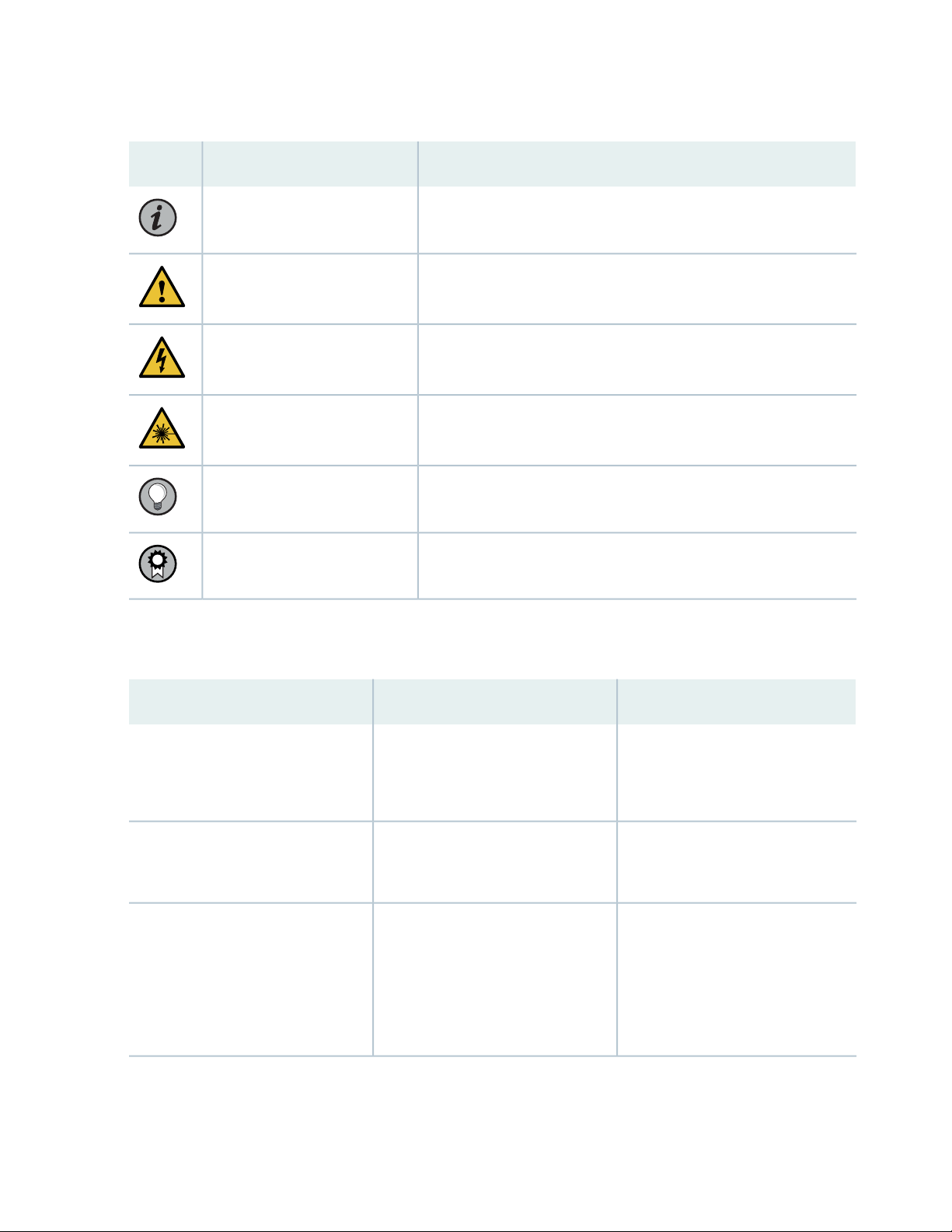
Table 1: Notice Icons
xiii
DescriptionMeaningIcon
Indicates important features or instructions.Informational note
Caution
Indicates a situation that might result in loss of data or hardware
damage.
Alerts you to the risk of personal injury or death.Warning
Alerts you to the risk of personal injury from a laser.Laser warning
Indicates helpful information.Tip
Alerts you to a recommended use or implementation.Best practice
Table 2 on page xiii defines the text and syntax conventions used in this guide.
Table 2: Text and Syntax Conventions
ExamplesDescriptionConvention
Fixed-width text like this
Italic text like this
Represents text that you type.Bold text like this
Represents output that appears on
the terminal screen.
Introduces or emphasizes important
•
new terms.
Identifies guide names.
•
Identifies RFC and Internet draft
•
titles.
To enter configuration mode, type
the configure command:
user@host> configure
user@host> show chassis alarms
No alarms currently active
A policy term is a named structure
•
that defines match conditions and
actions.
Junos OS CLI User Guide
•
RFC 1997, BGP Communities
•
Attribute
Page 14

Table 2: Text and Syntax Conventions (continued)
xiv
ExamplesDescriptionConvention
Italic text like this
Text like this
< > (angle brackets)
| (pipe symbol)
Represents variables (options for
which you substitute a value) in
commands or configuration
statements.
Represents names of configuration
statements, commands, files, and
directories; configuration hierarchy
levels; or labels on routing platform
components.
variables.
Indicates a choice between the
mutually exclusive keywords or
variables on either side of the symbol.
The set of choices is often enclosed
in parentheses for clarity.
Configure the machine’s domain
name:
[edit]
root@# set system domain-name
domain-name
To configure a stub area, include
•
the stub statement at the [edit
protocols ospf area area-id]
hierarchy level.
The console port is labeled
•
CONSOLE.
stub <default-metric metric>;Encloses optional keywords or
broadcast | multicast
(string1 | string2 | string3)
# (pound sign)
[ ] (square brackets)
Indention and braces ( { } )
; (semicolon)
GUI Conventions
Indicates a comment specified on the
same line as the configuration
statement to which it applies.
Encloses a variable for which you can
substitute one or more values.
Identifies a level in the configuration
hierarchy.
Identifies a leaf statement at a
configuration hierarchy level.
rsvp { # Required for dynamic MPLS
only
community name members [
community-ids ]
[edit]
routing-options {
static {
route default {
nexthop address;
retain;
}
}
}
Page 15
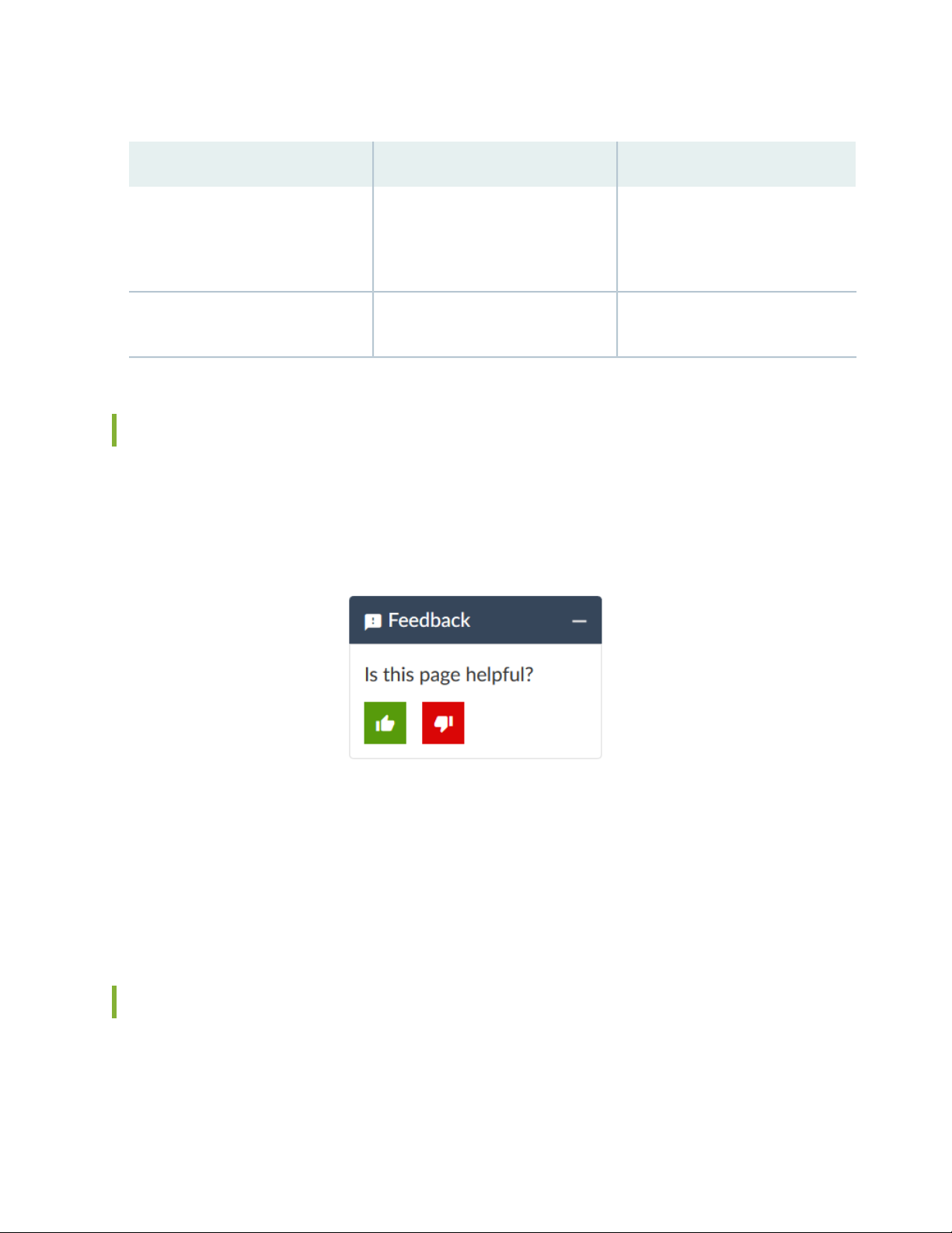
Table 2: Text and Syntax Conventions (continued)
xv
ExamplesDescriptionConvention
Bold text like this
> (bold right angle bracket)
Represents graphical user interface
(GUI) items you click or select.
Separates levels in a hierarchy of
menu selections.
In the Logical Interfaces box, select
•
All Interfaces.
To cancel the configuration, click
•
Cancel.
In the configuration editor hierarchy,
select Protocols>Ospf.
Documentation Feedback
We encourage you to provide feedback so that we can improve our documentation. You can use either
of the following methods:
Online feedback system—Click TechLibrary Feedback, on the lower right of any page on the Juniper
•
Networks TechLibrary site, and do one of the following:
Click the thumbs-up icon if the information on the page was helpful to you.
•
Click the thumbs-down icon if the information on the page was not helpful to you or if you have
•
suggestions for improvement, and use the pop-up form to provide feedback.
E-mail—Send your comments to techpubs-comments@juniper.net. Include the document or topic name,
•
URL or page number, and software version (if applicable).
Requesting Technical Support
Technical product support is available through the Juniper Networks Technical Assistance Center (JTAC).
If you are a customer with an active Juniper Care or Partner Support Services support contract, or are
Page 16

covered under warranty, and need post-sales technical support, you can access our tools and resources
online or open a case with JTAC.
JTAC policies—For a complete understanding of our JTAC procedures and policies, review the JTAC User
•
Guide located at https://www.juniper.net/us/en/local/pdf/resource-guides/7100059-en.pdf.
Product warranties—For product warranty information, visit https://www.juniper.net/support/warranty/.
•
JTAC hours of operation—The JTAC centers have resources available 24 hours a day, 7 days a week,
•
365 days a year.
Self-Help Online Tools and Resources
For quick and easy problem resolution, Juniper Networks has designed an online self-service portal called
the Customer Support Center (CSC) that provides you with the following features:
Find CSC offerings: https://www.juniper.net/customers/support/
•
Search for known bugs: https://prsearch.juniper.net/
•
xvi
Find product documentation: https://www.juniper.net/documentation/
•
Find solutions and answer questions using our Knowledge Base: https://kb.juniper.net/
•
Download the latest versions of software and review release notes:
•
https://www.juniper.net/customers/csc/software/
Search technical bulletins for relevant hardware and software notifications:
•
https://kb.juniper.net/InfoCenter/
Join and participate in the Juniper Networks Community Forum:
•
https://www.juniper.net/company/communities/
Create a service request online: https://myjuniper.juniper.net
•
To verify service entitlement by product serial number, use our Serial Number Entitlement (SNE) Tool:
https://entitlementsearch.juniper.net/entitlementsearch/
Creating a Service Request with JTAC
You can create a service request with JTAC on the Web or by telephone.
Visit https://myjuniper.juniper.net.
•
Call 1-888-314-JTAC (1-888-314-5822 toll-free in the USA, Canada, and Mexico).
•
For international or direct-dial options in countries without toll-free numbers, see
https://support.juniper.net/support/requesting-support/.
Page 17

1
PART
Overview
Overview | 2
Page 18
CHAPTER 1
Overview
IN THIS CHAPTER
J-Web User Interface for EX Series Switches Overview | 2
J-Web Interface—Application Package | 6
Understanding J-Web User Interface Sessions | 9
Dashboard for EX Series Switches | 10
Understanding J-Web Configuration Tools | 37
Understand Alarm Types and Severity Levels on EX Series Switches | 39
Using the Commit Options to Commit Configuration Changes (J-Web Procedure) | 40
2
J-Web User Interface for EX Series Switches Overview
Juniper Networks EX Series Ethernet Switches are shipped with the Juniper Networks Junos operating
system (Junos OS) installed.
Junos OS has the following primary user interfaces:
Juniper Web Device Manager (J-Web) GUI
•
Junos OS CLI
•
You can use these interfaces to access, configure, and manage your EX Series switch.
This topic provides an overview of the J-Web interface. For information about the CLI, see CLI User Interface
Overview.
J-Web Packages
For Junos OS Release 14.1X53-D10 and later, the J-Web interface is available in two packages:
Platform package—Provides basic features of J-Web and is installed as part of Junos OS.
•
Application package—Provides complete features of J-Web and is an installable package.
•
Platform Package
Page 19

The Platform package of J-Web is installed as part of Junos OS that is shipped with your EX Series
switch. The Platform package provides the basic features of the J-Web interface. The Platform package
enables you to configure and maintain your switch.
Application Package
The Application package is not installed by default on your switch. You must download it and install it
over the Platform package on your switch. The Application package provides all the features of the
J-Web interface that enable you to configure, monitor, maintain, and troubleshoot your switch.
The Platform package, which is installed as part of the Junos OS that is shipped with your switch, follows
the Junos OS release cycle. However, the Application packages have their own release cycle which is
independent of the Junos OS release cycle. This separate release cycle helps you get the latest features
of J-Web by installing the latest version of the Application package, without waiting for Junos OS releases.
NOTE: The J-Web Application package is hot-pluggable. You can install it on top of the current
Junos OS installation, and you need not reboot the switch after the installation.
3
NOTE: To determine which J-Web package you are currently using, click Help > About. The
About window appears. If you are using a Platform package, only the Platform package details
are displayed. If you are using an Application package, then the Platform package and Application
package details are displayed.
If your current J-Web
package is:
Application package
Then you can:
Upgrade to the Application package.Platform package
Update to a latest version of the Application package available on the Juniper
Networks server that is compatible with the Junos OS on your switch.
NOTE: If you upgrade Junos OS on your switch, the current J-Web package is
replaced with the J-Web Platform package that is associated with the upgraded
Junos OS release. You can then install the latest Application package that is associated
with the main release of the upgraded Junos OS, over the Platform package.
Page 20

Release Compatibility
The Application packages of J-Web have their own release cycles (A1, A2, A3, and so on), which are
independent of the Junos OS release cycle. An Application package is compatible only with the
corresponding major release of Junos OS.
The Table 3 on page 4 illustrates the example of the release compatibility.
Table 3: J-Web Release Compatibility Matrix
Associated J-Web Application Package ReleaseJunos OS Release
Application package 14.1X53-A114.1X53-D10
Application package 14.1X53-A214.1X53-D35
Application package 15.1A115.1R1
4
15.1R3
Application package 15.1A2
NOTE: Application package 15.1A2 cannot be installed on Junos OS Release
15.1R1.
Application package 15.1A3 (if applicable)
16.1A116.1R1
Application package 17.1A117.1R1
Application package 17.2A117.2R1
Application package 17.3A117.3R1
Application package 15.1X53-A215.1X53-D57
Application package 17.4A117.4R1
Application package 18.1A118.1R1
Application package 18.1A218.1R2
Application package 18.2A118.2R1
Application package 18.3A118.3R1
Application package 18.4A118.4R1
Page 21

Any available later version of the Application package for a Junos OS release supersedes the earlier version.
Thus, if Application package version 15.1A2 is available for 15.1R1, it will supersede version 15.1A1. We
recommend that you install the latest available version of the Application package.
Software Requirements
To access the J-Web interface, your management device requires the following software:
Supported browsers—Microsoft Internet Explorer version 9 or 10, Mozilla Firefox version 24 through
•
30, and Google Chrome version 27 through 36.
TIP: For best viewing of the J-Web user interface, set the screen resolution to 1440 X 900
pixels.
NOTE: Other browser versions might not work on the switch. The browser and the network
must support receiving and processing HTTP 1.1 GZIP compressed data.
5
Language support—English-version browsers
•
Release History Table
DescriptionRelease
Application package 15.1A2 cannot be installed on Junos OS Release 15.1R1.15.1R1
14.1X53-D10
For Junos OS Release 14.1X53-D10 and later, the J-Web interface is available in
two packages
RELATED DOCUMENTATION
FAQ: J-Web Application Package on EX Series Switches
EX Series Switch Software Features Overview
CLI User Interface Overview
Page 22

J-Web Interface—Application Package
NOTE: This topic applies only to the J-Web Application package.
With the J-Web Application package, you can:
Get a high-level, graphical view of the chassis and the status of the switch, such as the system health
•
information, alarms, or system status.
Configure the switch, and view the configuration history.
•
Monitor the switch by viewing information about configuration and hardware on the switch such as
•
events, alarms, security, and routing options.
Maintain the switch by updating the J-Web interface, upgrading Junos OS, uploading configurations,
•
managing licenses and files, or rebooting the switch.
6
NOTE: Juniper Networks devices require a license to activate the feature. Refer to the Licensing
Guide for general information about License Management: Licenses for Network Management.
To understand more about managing licences through J-Web, see “Managing Licenses for the
EX Series Switch (J-Web Procedure)” on page 202.
Troubleshoot network issues by running diagnostic tools. Troubleshoot interface configuration and faults
•
by using ping, traceroute, or packet capture, or by using the CLI terminal.
J-Web Application Package—First Look
Each page of the J-Web interface is divided into panes.
Top pane—It is located at the top of the page. It displays the J-Web logo and hostname, tasks–Configure,
•
Monitor, and Maintain, Commit, Update Available logo (if available), and username and Help.
Side pane—It is located on the left side of the page. It displays suboptions of the tasks–Monitor, Configure,
•
or Maintain– currently selected in the top pane. Click a suboption to access it in the work area.
Work area—This is the main work area of the J-Web interface, located below the top pane and to the
•
right of the side pane. It displays various text boxes, selection boxes, buttons and other options
corresponding to the suboption that you select in the side pane. It is the location where you monitor,
configure, and manage (maintain) the switch.
The layout of the panes enables you to quickly navigate through the interface. Table 4 on page 7
summarizes the elements of the J-Web interface.
Page 23

The J-Web interface provides CLI tools that enable you to perform all of the tasks that you can perform
from the Junos OS CLI, including a CLI Viewer to view the current configuration, a CLI Editor for viewing
and modifying the configuration, and a Point & Click CLI editor that enables you to click through all of the
available CLI statements.
Table 4: J-Web Application Package Interface Elements
DescriptionElement
Top Pane
The J-Web logo and hostname of the switch.J-Web
Hostname
7
Taskbar
Menu that displays the main options. Click the tab to access an option.
Configure—Configure the switch, and view the configuration history.
•
Monitor—View information about configuration and hardware on the switch
•
such as events, alarms, security, and routing options.
Maintain—Update the J-Web interface, upgrade Junos OS, upload
•
configurations, manage licenses and files, and reboot the switch.
Troubleshoot—Run diagnostic tools to troubleshoot network issues.
•
Troubleshoot interface configuration and faults by using ping, traceroute, or
packet capture, or by using the CLI terminal.
Page 24

Table 4: J-Web Application Package Interface Elements (continued)
DescriptionElement
8
Commit Options
A set of options using which you can configure committing multiple changes
with a single commit.
Commit—Commits the candidate configuration of the current user session,
•
along with changes from other user sessions.
Compare—Displays the XML log of pending configurations on the device.
•
Discard—Discards the candidate configuration of the current user session,
•
along with changes from other user sessions.
Preference—Indicates your choice of committing all configurations changes
•
together or committing each configuration change immediately. The two
commit options are:
Validate configuration changes—Loads all configuration changes for an
•
accumulated single commit. If there are errors in loading the configuration,
the errors are logged. This is the default mode.
Validate and commit configuration changes—Sets the system to force an
•
immediate commit on every page after every configuration change.
NOTE: There are some pages on which configuration changes must be
committed immediately. For such pages, if you configure the commit options
for a single commit, the system displays warning notifications that remind
you to commit your changes immediately. An example of such a page is the
Ports page (Configure > Interfaces > Ports).
Update Available
username
Help
This icon message appears only if there is a J-Web Application package update
available on the Juniper Networks server.
Mouse over the icon to know the latest version of J-Web Application package
available on the Juniper Networks server. Click on the icon to update the J-Web
Application package.
The username you used to log in to the switch.
The down arrow option displays the Logout option. Logout ends your current
session and returns you to the login page.
Displays links to help topics and information about the J-Web interface.
Help Contents—Provides context-sensitive help topics.
•
About—Displays information about the J-Web interface, such as the version
•
number.
Page 25

Table 4: J-Web Application Package Interface Elements (continued)
DescriptionElement
9
Icon legend
Work Area
Configuration hierarchy
(Applies to the Point & Click CLI editor only) Explains icons that appear in the
user interface to provide information about configuration statements:
C—Comment. Mouse over the icon to view a comment about the configuration
•
statement.
I—Inactive. The configuration statement does not apply for the switch.
•
M—Modified. The configuration statement has been added or modified.
•
*—Mandatory. The configuration statement must have a value.
•
(Applies to the Junos OS CLI configuration editor only) Displays the hierarchy
of committed statements in the switch configuration.
Click Expand all to display the entire hierarchy.
•
Click Hide all to display only the statements at the top level.
•
Click + to expand individual items.
•
Click - to hide individual items.
•
RELATED DOCUMENTATION
Using the Commit Options to Commit Configuration Changes (J-Web Procedure) | 40
EX Series Switch Software Features Overview
Connecting and Configuring an EX Series Switch (J-Web Procedure) | 54
CLI User Interface Overview
Understanding J-Web User Interface Sessions
You establish a J-Web session with the switch through an HTTP-enabled or HTTPS-enabled Web browser.
To use HTTPS, you must have installed a certificate on the switch and enabled HTTPS. See Generating SSL
Certificates to Be Used for Secure Web Access (EX Series Switch).
When you attempt to log in through the J-Web interface, the switch authenticates your username with
the same methods used for Telnet and SSH.
Page 26

If the switch does not detect any activity through the J-Web interface for 15 minutes, the session times
out and is terminated. You must log in again to begin a new session.
To explicitly terminate a J-Web session at any time, click Logout in the top pane.
RELATED DOCUMENTATION
J-Web User Interface for EX Series Switches Overview | 2
Configuring Management Access for the EX Series Switch (J-Web Procedure) | 61
Dashboard for EX Series Switches
IN THIS SECTION
10
Graphical Chassis Viewer | 11
System Information Panel | 13
Health Status Panel | 16
Capacity Utilization Panel | 20
Alarms Panel | 20
File System Usage | 21
Chassis Viewer | 21
NOTE: This topic applies only to the J-Web Application package.
When you log in to the J-Web user interface, the dashboard for the Juniper Networks EX Series Ethernet
Switches appears. Use the dashboard to view system information.
The Update Available window appears if there is a latest update of the J-Web Application package available
on the Juniper Networks server. This window is enabled by the auto update feature of J-Web.
Page 27

NOTE:
The Update Available window will not appear when you log in, if you have not selected the
•
Check for updates automatically on every login in the Update Preference section in the Maintain
> Update J-Web side pane. By default, the Check for update automatically on every login is
selected.
If you choose Update Later, you can update to the latest J-Web Application package by clicking
•
the orange icon next to Update Available on the top pane of the J-Web interface or through
Maintain > Update J-Web.
The dashboard comprises a graphical chassis viewer and four panels.
Graphical Chassis Viewer
The Dashboard panel displays a graphical view of the chassis of a switch. In a Virtual Chassis, it displays
a graphical view of each member switch.
11
In a Virtual Chassis, the default values are shown on the Dashboard panel when no chassis image is clicked.
The panel displays the value for a switch if you click its image.
NOTE:
If the member switch is not present, inactive, or not provisioned, you cannot expand the
•
member switch image.
In J-Web Application package Release 14.1X53-A2, you can form a Virtual Chassis using
EX4600 and EX4300 switches. When in a mixed Virtual Chassis consisting of EX4600 switches
and EX4300 switches, the EX4600 switches can be the primary, backup, or in the linecard role,
while the EX4300 switches must be in the linecard role.
Starting in J-Web Application Package Release 19.2A1, J-Web supports EX4650 switches.
•
NOTE: For EX4650 switches, chassis viewer supports only the standalone view and
does not support the Virtual Chassis configuration.
Table 5 on page 12 lists the details that are displayed on each member switch.
Page 28

Table 5: Details of a Virtual Chassis Member Switch
ExampleDetails
EX3300Model number of the member switch
12
Assigned ID that applies to the entire Virtual Chassis
configuration
Role of the member switch
Status of the member switch
ID 2
NOTE: If the member switch is not provisioned, the serial
number of the switch is displayed instead of its ID.
Master
Possible roles are: Master, Backup, or Linecard
Prsnt
Possible statuses are: Prsnt, NotPrsnt, Inactive, or Unprvsnd
The status of the member switch is displayed on the image of the switch. If the member switch appears
dimmed, it means the switch is not present, is inactive, or is not provisioned in the Virtual Chassis. If the
member switch does not appear dimmed, it means the switch is present and is active.
Table 6 on page 12 describes the possible status of a member switch.
Table 6: Status of a Member Switch in a Virtual Chassis
It means the member switchIt appears asIf the member switch is
Has established physical and logical connections with
Virtual Chassis member switches.
Has been disconnected from the existing Virtual Chassis.dimmed and
Has established physical connections, but is unable to
establish logical connections.
Cannot synchronize with the existing preprovisioned Virtual
Chassis.
Not present
Inactive
Not provisioned
PrsntPresent
NotPrsnt
dimmed and
Inactive
dimmed and
Unprvsnd
Click Rear View for a graphical view of the rear panel of the switch.
Page 29

Click Preferences to choose which panels must be displayed and set the refresh interval for chassis viewer
information. Click OK to save your changes and return to the dashboard or click Cancel to return to the
dashboard without saving changes.
NOTE: You can drag the various panels to different locations in the J-Web window.
System Information Panel
Table 7: System Information
DescriptionField
13
System name
Device model
Indicates the local name of the EX Series switch. The local
name of the EX Series switches changes when an individual
image is clicked.
For EX4650 switches, indicates the host name of the
switch. Specific host name of the EX4650 switch is
displayed when you click on the individual line card.
Indicates the model of the EX Series switch. In a Virtual
Chassis configuration, to indicate the model of a switch,
click the image of that switch.
NOTE: In a Virtual Chassis setup for an EX6210, EX8208,
or EX8216 switch, the Device model field displays details
of the primary Routing Engine. To view details of a
member, select it.
By default, the EX4650 switches show the model of the
primary switch. When you click on the image, the model
of the switch is displayed.
Page 30

Table 7: System Information (continued)
Inventory details
14
DescriptionField
Page 31

Table 7: System Information (continued)
DescriptionField
Indicates the following:
For EX3200 switches; and for EX2200, EX2200-C,
•
EX3300, EX4200, EX4300, EX4500, EX4550, and
EX4600 switches that are not configured as Virtual
Chassis, the value displayed in Inventory details field is
always 1 FPC. FPC is a legacy term for a slot in a large
Juniper Networks chassis; which simply refers to the
standalone switch.
For EX2200 and EX2200-C switches configured as a
•
Virtual Chassis, the value displayed in the Inventory
details field is 1–4 FPC, with the number corresponding
to the number of member switches.
For EX3300 switches configured as a Virtual Chassis,
•
the value displayed in the Inventory details field is 1–6
FPC, with the number corresponding to the number of
member switches.
15
NOTE: For Junos OS Release 14.1X53-D10 and later,
EX3300 switches configured as a Virtual Chassis display
the value 1–10 FPC in the Inventory details field.
For EX4200, EX4500, EX4550, and EX4600 switches
•
configured as a Virtual Chassis, the value displayed in
the Inventory details field is 1–10 FPC, with the number
corresponding to the number of member switches.
For EX4650 switches, the value displayed in Inventory
•
details field is equal to the number of FPCs.
For EX6210 switches, the values displayed in the
•
Inventory details field are 1–2 CB and 1–9 FPC. CB, or
Control Board, refers to the SRE module. FPC refers to
line cards and the FPC within the CB.
For an EX8208 switch, the values displayed in Inventory
•
details field are 1–3 CB and 0–8 FPC. CB, or Control
Board, refers to SRE and SF modules. FPC refers to line
cards.
For EX8216 switches, the values displayed in Inventory
•
details field are 1–2 CB and 0–16 FPC. CB, or Control
Board, refers to RE modules and FPC refers to line cards.
For an XRE200 External Routing Engine in an EX8200
•
Virtual Chassis, the value displayed in Inventory details
is 1 XRE. XRE refers to RE modules. For XRE200
Page 32

Table 7: System Information (continued)
16
DescriptionField
External Routing Engines configured as a Virtual Chassis,
the values displayed in Inventory details are 1–2 XRE
and 0–4 LCC, where LCC refers to the EX8200 line card
chassis.
Junos image
Boot image
Device uptime
Indicates the version of the Junos OS image. In a Virtual
Chassis configuration, the Junos OS image of the primary
switch is displayed by default. To display the Junos OS
image of a specific switch, click the image of that switch.
NOTE: For EX4650 switches, the Junos OS image of the
primary is displayed by default. To display the Junos OS
image of a specific switch, click the image of that switch.
Indicates the version of the boot image that is used. In a
Virtual Chassis configuration, the boot image of the
primary switch is displayed by default. To display the boot
image of a specific switch, click the image of that switch.
NOTE: For EX4650 switches, the boot image of the
primary switch is displayed by default. To display the boot
image of a specific switch, click the image of that switch.
Indicates the time since the last reboot. In a Virtual Chassis
configuration, to display the uptime of the specific switch,
click the image of that switch.
NOTE: For EX4650 switches, click the image of the switch
to display the uptime.
Indicates the time when the switch was last configured.Last configured time
Health Status Panel
Table 8: Health Status
DescriptionField
EX2200, EX2200-C, EX3200, EX3300, EX4200, and EX4300 Switches
Page 33

Table 8: Health Status (continued)
DescriptionField
17
Memory util.
Flash
Temp.
Indicates the memory used in the Routing Engine. In a Virtual Chassis configuration, the
memory utilization value of the primary Routing Engine is displayed.
NOTE: In EX4300 and EX4600 Virtual Chassis, to display the Routing Engine memory
utilization of the primary or backup, click the respective image. J-Web is supported on
EX4600 switches only in J-Web Application package Release 14.1X53-A2.
Indicates the usage and capacity of internal flash memory and any external USB flash drive.
NOTE: In EX4300 Virtual Chassis, the flash memory utilization of the primary switch is
displayed by default. To display the flash memory utilization along with the internal and
external flash memory utilization details for each switch or line card, mouse over individual
switch or line card images.
In EX4600 Virtual Chassis, to display the flash memory utilization along with the internal
and external flash memory utilization details of each switch or line card mouse over the
green-colored indicator.
Indicates the chassis temperature status. Temperatures are listed in Celsius and the
corresponding Fahrenheit values.
NOTE: The Temp field is unavailable for a standalone EX2200-C switch.
CPU load
The Temp field is dynamically available for an EX2200 Virtual Chassis switch based on the
model of the member clicked.
NOTE: In EX4300 Virtual Chassis, the temperature of the primary Routing Engine is displayed
by default. To display the temperature of the Routing Engine of any switch, click the image
of that switch.
In EX4600 Virtual Chassis, to display the temperature of the Routing Engine of each switch,
mouse over the green-colored indicator.
Indicates the average CPU usage over 15 minutes. In a Virtual Chassis configuration, on
loading the primary or backup switch, the CPU load for that switch's Routing Engine is
displayed by default. To display the CPU load for a specific switch's Routing Engine, click
the image of that switch.
Page 34

Table 8: Health Status (continued)
DescriptionField
18
Fan status
Indicates the status of the fans in the fan tray. The possible values are OK, Failed, and Absent.
In a Virtual Chassis configuration, the fan status of the primary switch is displayed by default.
To display the fan status for any switch , click the image of that switch.
NOTE: The Fan status field is unavailable for a standalone EX2200-C switch.
The Fan status field is dynamically available for an EX2200 Virtual Chassis switch based on
the model of the member clicked.
In EX4600 Virtual Chassis, mouse over the fan icon to display the fan status of all the
switches.
EX4500 and EX4550 Switches
Memory util.
Temp.
Indicates the memory used in the Routing Engine. In a Virtual Chassis configuration, the
memory utilization value of the primary Routing Engine is displayed.
Indicates the usage and capacity of internal flash memory and any external USB flash drive.Flash
Indicates the chassis temperature status. Temperatures in the dashboard are listed in Celsius
and the corresponding Fahrenheit values.
NOTE: The Temp field is unavailable for an EX4500 switch.
Fan status
EX4650 Switches
Fan status
EX6210 Switches
Indicates the average CPU usage over 15 minutes.CPU load
Indicates the status of the fans in the fan tray. The possible values are OK, Failed, and Absent.
This field also indicates the direction of airflow of the fan tray. The possible values are Front
to back and Back to front.
Indicates the status of the fans in the fan tray. The possible values are OK, Failed, and Absent.
NOTE: The fans are located on the side panel of the chassis.
Indicates temperature of the sensor near to Routing Engine.Temp.
Indicates the memory used in the Routing Engine.Memory util.
Indicates the average CPU usage over 15 minutes.CPU load
Page 35

Table 8: Health Status (continued)
DescriptionField
19
Memory util.
EX8208 Switches
Memory util.
EX8216 Switches
Indicates the memory used in the primary Routing Engine. Click the backup Routing Engine
to view the memory used in the backup Routing Engine.
Indicates the average CPU usage over 15 minutes.CPU load
Indicates the usage and capacity of internal flash memory and any external USB flash drive.Flash
Indicates the status of the fans in the fan tray. The possible values are OK, Failed, and Absent.Fan status
Indicates the memory used in the external Routing Engine. In an EX8200 Virtual Chassis,
the memory utilization value of the XRE200 External Routing Engine in the primary role is
displayed. Click the XRE200 External Routing Engine in the backup role to view the memory
used in the backup external Routing Engine.
Indicates the average CPU usage over 15 minutes.CPU load
Indicates the usage and capacity of internal flash memory and any external USB flash drive.Flash
Memory util.
Indicates the memory used in the external Routing Engine. In an EX8200 Virtual Chassis,
the memory utilization value of the XRE200 External Routing Engine in the primary role is
displayed. Click the XRE200 External Routing Engine in the backup role to view the memory
used in the backup external Routing Engine.
Indicates the average CPU usage over 15 minutes.CPU load
Indicates the usage and capacity of internal flash memory and any external USB flash drive.Flash
XRE200 External Routing Engines
Memory util.
Indicates the memory used in the external Routing Engine. In an EX8200 Virtual Chassis,
the memory utilization value of the XRE200 External Routing Engine in the primary role is
displayed. Click the backup XRE200 External Routing Engine to view the memory used in
backup external Routing Engine.
Indicates the average CPU usage over 15 minutes.CPU load
Indicates the usage and capacity of internal flash memory and any external USB flash drive.Flash
Page 36

Table 8: Health Status (continued)
DescriptionField
Indicates the status of the fans in the fan tray. The possible values are OK, Failed, and Absent.Fan Status
Capacity Utilization Panel
Table 9: Capacity Utilization
20
DescriptionField
Number of active ports
Total number of ports
Supported MAC-Table entries
Number of VLANs configured
Indicates the number of active ports in the switch.
Configured Virtual Chassis ports (VCPs) are considered as
active ports.
Indicates the number of ports in the switch.
NOTE: In EX3300 and EX4600 Virtual Chassis, the total
number of ports of all of the switches is displayed.
NOTE: For EX4650 switches, on loading the switch, the
consolidated values for all the FPCs are displayed by
default.
Indicates the number of MAC table entries.Used-up MAC-Table entries
Indicates the maximum number of MAC table entries
permitted.
NOTE: For EX4650 switches, the supported maximum
number of MAC table entries are 288000.
Indicates the number of VLANs configured.
NOTE: Only tagged VLANs are counted.
Number of VLANs supported
Indicates the maximum number of VLANs supported.
NOTE: For EX4650 switches, the supported maximum
number of VLANs are 4094.
Alarms Panel
Displays information about the last five alarms raised in the system. For example, if there are 5 major
alarms, then details of all 5 major alarms are displayed. If there are 4 major alarms and 3 minor alarms,
Page 37

then details of the 4 major alarms and 1 minor alarm are displayed. Major alarms are displayed in red and
minor alarms are displayed in yellow.
In an EX8200 Virtual Chassis, the top 5 alarms for the primary external Routing Engine are displayed by
default. If you select an EX8200 member switch of the Virtual Chassis, the top 5 alarms for that member
switch are displayed.
File System Usage
To display the file system storage details of a switch in the backup or line card role, click the image of that
switch.
For EX4650 switches, the directory, space used, and the file type details are displayed. By default, primary
switch file system storage details are displayed. When you click the image, line card switch file system
storage details are displayed.
Chassis Viewer
21
Click the Rear View button to see the back of the chassis image. Click the Front View button to see the
front of the chassis image. In a Virtual Chassis configuration, the Rear View button is disabled if the switch
is not selected.
NOTE: For EX4650 switches, chassis viewer supports only the standalone view and does not
support Virtual Chassis configuration.
Table 10 on page 22—Describes the chassis viewer for EX2200 switches.
•
Table 11 on page 22—Describes the chassis viewer for EX2200-C switches.
•
Table 12 on page 23—Describes the chassis viewer for EX3200, EX3300, and EX4200 switches.
•
Table 13 on page 25—Describes the chassis viewer for EX4300 switches.
•
Table 14 on page 26—Describes the chassis viewer for EX4500 switches.
•
Table 15 on page 28—Describes the chassis viewer for EX4550 switches.
•
Table 16 on page 29—Describes the chassis viewer for EX4600 switches.
•
Table 17 on page 30—Describes the chassis viewer for EX4650 switches.
•
Table 18 on page 31—Describes the chassis viewer for EX6210 switches.
•
Table 19 on page 32—Describes the chassis viewer for EX8208 switches.
•
Table 20 on page 34—Describes the chassis viewer for EX8216 switches.
•
Table 21 on page 35—Describes the chassis viewer for the XRE200 External Routing Engines.
•
Page 38

Table 10: Chassis Viewer for EX2200 Switches
DescriptionField
Front View
22
Interface status
Rear View
Management (me0) port
Console port
USB port
In the image, the following colors denote the interface status:
Green—Interface is up and operational.
•
Yellow—Interface is up but is nonoperational.
•
Gray—Interface is down and nonoperational.
•
Mouse over the interface (port) to view more information.
The management port is used to connect the switch to a management device for
out-of-band management.
The console port is used to connect the switch to a management console or to a console
server. (You might do this for initial switch configuration.)
Indicates the USB port for the switch.
NOTE: We recommend that you use USB flash drives purchased from Juniper Networks
for your EX Series switch.
Mouse over the fan tray icon to display name, status, and description information.Fan tray
Mouse over the power outlet icon to display name, status, and description information.Power supply
Table 11: Chassis Viewer for EX2200-C Switches
DescriptionField
Front View
Interface status
Management (me0) port
In the image, the following colors denote the interface status:
Green—Interface is up and operational.
•
Yellow—Interface is up but is nonoperational.
•
Gray—Interface is down and nonoperational.
•
Mouse over the interface (port) to view more information.
The management port is used to connect the switch to a management device for
out-of-band management.
Page 39

Table 11: Chassis Viewer for EX2200-C Switches (continued)
DescriptionField
23
Console port
USB port
The console port is used to connect the switch to a management console or to a console
server. (You might do this for initial switch configuration.)
Indicates the USB port for the switch.
NOTE: We recommend that you use USB flash drives purchased from Juniper Networks
for your EX Series switch.
Rear View
Mouse over the power outlet icon to display name, status, and description information.Power supply
Table 12: Chassis Viewer for EX3200, EX3300, and EX4200 Switches
DescriptionField
Front View
Interface status
In the image, the following colors denote the interface status:
Green—Interface is up and operational.
•
Yellow—Interface is up but is nonoperational.
•
Gray—Interface is down and nonoperational.
•
LCD panel
Mouse over the interface (port) to view more information.
For a Virtual Chassis configuration, select the switch to view the interface status.
If an SFP+ uplink module is installed in the switch, mouse over the port icon to display
whether the module is configured to operate in 1-gigabit mode or in 10-gigabit mode. If
the module is configured to operate in 1-gigabit mode, the tool tip information is displayed
for all 4 ports. If the module is configured to operate in 10-gigabit mode, the tool tip
information is displayed only for 2 ports.
On an EX3300 switch with the 4x GE/XE SFP+ module, mouse over the port icon to display
whether the module is configured to operate in 1-gigabit mode or 10-gigabit mode.
For SFP, SFP+, and XFP ports, the interfaces appear dimmed if no transceiver is inserted.
The chassis viewer displays Transceiver not plugged-in when you mouse over the port
icon.
LCD panel configured for the LEDs on the ports. Mouse over the icon to view the current
character display.
Page 40

Table 12: Chassis Viewer for EX3200, EX3300, and EX4200 Switches (continued)
DescriptionField
Rear View of the EX3200 Switch
24
Management (me0) port
Console port
USB port
The management port is used to connect the switch to a management device for
out-of-band management.
The console port is used to connect the switch to a management console or to a console
server. (You might do this for initial switch configuration.)
Indicates the USB port for the switch.
NOTE: We recommend that you use USB flash drives purchased from Juniper Networks
for your EX Series switch.
Mouse over the fan tray icon to display name, status, and description information.Fan tray
Mouse over the power supply icon to display name, status, and description information.Power supply
Rear View of the EX3300 and EX4200 Switch
Fan tray
Virtual Chassis port
Mouse over the fan tray icon to display name, status, and description information. For a
Virtual Chassis, the status of the fans of the selected member switch is displayed.
Displayed only when EX4200 switches are configured as a Virtual Chassis. The following
colors denote the Virtual Chassis port (VCP) status:
USB port
Management (me0) port
Console port
Green—VCP is up and operational.
•
Yellow—VCP is up but is nonoperational.
•
Gray—VCP is down and nonoperational.
•
Indicates the USB port for the switch.
NOTE: We recommend that you use USB flash drives purchased from Juniper Networks
for your EX Series switch.
The management port is used to connect the switch to a management device for
out-of-band management.
The console port is used to connect the switch to a management console or to a console
server. (You might do this for initial switch configuration.)
Mouse over the power supply icons to display name, status, and description information.Power supplies
Page 41

Table 13: Chassis Viewer for EX4300 Switches
DescriptionField
Front View
25
Interface status
LCD panel
PIC 2 slot
In the image, the colors listed below denote the interface status for both copper and fiber
media type of ports:
Green—Interface is up and operational.
•
Yellow—Interface is up but is nonoperational.
•
Gray—Interface is down and nonoperational.
•
Mouse over the interface (port) to view more information.
LCD panel configured for the LEDs on the ports. Mouse over the icon to view the current
character display.
The mini console port is used to connect the switch to the management console.Mini USB console
You can install an uplink module in the PIC 2 slot. Mouse over the ports in the module to
view the details of the ports in module.
24-port and 48-port EX4300 switches support the 4-port 10-Gigabit SFP+ uplink module.
EX4300-32F switches support the 2-port 40-Gigabit QSFP+ uplink module and the 8-port
10-Gigabit SFP+ uplink module.
When you install a transceiver in the port, the following colors denote the interface status:
Green—Interface is up and operational.
•
Yellow—Interface is up but is not operational.
•
Gray—Interface is down and not operational.
•
NOTE: In EX4300 switches the LEDs are seen in the front panel, these are not active.
Rear View of the EX4300 Switch
Management port
Console port
USB port
The management port is used to connect the switch to a management device for out-of-band
management.
The Console port (RJ-45) is used to connect the switch to a management console or to a
console server.
Indicates the USB port for the switch.
NOTE: We recommend that you use USB flash drives purchased from Juniper Networks
for your EX Series switch.
Page 42

Table 13: Chassis Viewer for EX4300 Switches (continued)
DescriptionField
Mouse over the fan tray icons to display name, status, and description information.Fan tray
Mouse over the power supply icons to display name, status, and description information.Power supplies
26
PIC 1 slot
The rear panel of a 24-port and a 48-port EX4300 switch has four (built-in) 40-Gigabit
QSFP+ ports, and the rear panel of an EX4300-32F switch has two (built-in) 40-Gigabit
QSFP+ ports, in which you can install QSFP+ transceivers. Mouse over the ports to view
the details of the ports.
After you install a transceiver in the port, the following colors denote the interface status:
Green—Interface is up and operational.
•
Yellow—Interface is up but is not operational.
•
Gray—Interface is down and not operational.
•
For QSFP+ ports, the interfaces appear dimmed if no transceiver is inserted. The chassis
viewer displays Transceiver not plugged in when you mouse over the port.
When a QSFP+ port is configured as a Virtual Chassis Port (VCP), the following colors denote
the VCP status:
Green—VCP is up and operational.
•
Yellow—VCP is up but is not operational.
•
Gray—VCP is down and not operational.
•
Table 14: Chassis Viewer for EX4500 Switches
Front View
DescriptionField
Page 43

Table 14: Chassis Viewer for EX4500 Switches (continued)
DescriptionField
27
Interface status
LCD panel
Console port
Management (me0) port
In the image, the colors listed below denote the interface status:
Green—Interface is up and operational.
•
Yellow—Interface is up but is nonoperational.
•
Gray—Interface is down and nonoperational.
•
Mouse over the interface (port) to view more information.
For a Virtual Chassis configuration, select the switch to view the interface status.
If an SFP+ uplink module is installed in the switch, mouse over the interface (ports) on
the module for more information.
For SFP and SFP+ ports, the interfaces appear dimmed if no transceiver is inserted. The
chassis viewer displays Transceiver not plugged-in when you mouse over the port icon.
LCD panel configured for the LEDs on the ports. Mouse over the icon to view the current
character display.
The console port is used to connect the switch to a management console or to a console
server.
The management port is used to connect the switch to a management device for
out-of-band management. Use this port for initial switch configuration.
USB port
Indicates the USB port for the switch.
NOTE: We recommend that you use USB flash drives purchased from Juniper Networks
for your EX Series switch.
Rear View of the EX4500 Switch
Fan tray
Virtual Chassis port
Mouse over the fan tray icon to display status of the fans and airflow direction information.
For a Virtual Chassis, the status of the fans of the selected member switch is displayed.
Displayed only when switches are configured as a Virtual Chassis. The colors listed below
denote the Virtual Chassis port (VCP) status:
Green—VCP is up and operational.
•
Yellow—VCP is up but is nonoperational.
•
Gray—VCP is down and nonoperational.
•
Mouse over the power supply icons to display name, status, and description information.Power supplies
Page 44

Table 14: Chassis Viewer for EX4500 Switches (continued)
DescriptionField
28
Intraconnect module
Mouse over the module to display details of the intraconnect module. The intraconnect
module helps the switch achieve line rate on all its ports.
Mouse over to display details of the switches in the Virtual Chassis configuration.Virtual Chassis module
Table 15: Chassis Viewer for EX4550 Switches
DescriptionField
Front View
Interface status
In the image, the colors listed below denote the interface status:
Green—Interface is up and operational.
•
Yellow—Interface is up but is nonoperational.
•
Gray—Interface is down and nonoperational.
•
Mouse over the interface (port) to view more information.
For a Virtual Chassis configuration, select the switch to view the interface status.
If an expansion module or a Virtual Chassis module is installed in the switch, mouse over
the interface (ports) on the module for more information.
LCD panel
Console port
Management (me0) port
PIC1 slot
On an EX4550-32F switch, for SFP and SFP+ ports, the interfaces appear dimmed if no
transceiver is inserted. The chassis viewer displays Transceiver (1G/10G) not plugged in
when you mouse over the port icon.
LCD panel configured for the LEDs on the ports. Mouse over the icon to view the current
character display.
The console port is used to connect the switch to a management console or to a console
server.
The mini console port is used to connect the switch to the management console.Mini Console port
The management port is used to connect the switch to a management device for out-of-band
management. Use this port for initial switch configuration.
You can insert an uplink module or a Virtual Chassis module in the PIC1 slot. Mouse over
to display the details of the module inserted (uplink or Virtual Chassis).
Page 45

Table 15: Chassis Viewer for EX4550 Switches (continued)
DescriptionField
29
USB port
Indicates the USB port for the switch.
NOTE: We recommend that you use USB flash drives purchased from Juniper Networks
for your EX Series switch.
Rear View of the EX4550 Switch
Fan tray
Virtual Chassis port
PIC2 slot
Mouse over the fan tray icon to display the status of the fans and airflow direction
information. For a Virtual Chassis, the status of the fans of the selected member switch is
displayed.
Displayed only when switches are configured as a Virtual Chassis. In the image, the colors
listed below denote the Virtual Chassis port (VCP) status:
Green—VCP is up and operational.
•
Yellow—VCP is up but is nonoperational.
•
Gray—VCP is down and nonoperational.
•
Mouse over the power supply icons to display name, status, and description information.Power supplies
You can insert an uplink module or a Virtual Chassis module into the PIC2 slot. Mouse over
to display the details of the module inserted (uplink or Virtual Chassis).
Table 16: Chassis Viewer for EX4600 Switches
DescriptionField
Front View
NOTE: J-Web is supported on EX4600 switches only in J-Web Application package Release 14.1X53-A2.
Interface status
In the image, the colors listed below denote the interface status for both copper
and fiber media type of ports:
Green—Interface is up and operational.
•
Yellow—Interface is up but is nonoperational.
•
Gray—Interface is down and nonoperational.
•
Mouse over the interface (port) to view more information.
Page 46

Table 16: Chassis Viewer for EX4600 Switches (continued)
DescriptionField
30
PIC 1 and PIC 2 slots
NOTE:
In EX4600 switches the LEDs are seen in the front panel; these are not active.
•
In EX4600 switches there is no LCD panel.
•
You can install an expansion module in the PIC 1 and PIC 2 slots. If you have
installed an expansion module, mouse over the ports in the module to view the
details of the ports in module.
When you install a transceiver in the port, the following colors denote the interface
status:
Green—Interface is up and operational.
•
Yellow—Interface is up but is not operational.
•
Gray—Interface is down and not operational.
•
Rear View of the EX4600 Switch
Management port
Console port
The management ports (RJ-45 and SFP) is used to connect the switch to a
management device for out-of-band management.
The Console port (RJ-45) is used to connect the switch to a management console
or to a console server.
USB port
Power supplies
Indicates the USB port for the switch.
NOTE: We recommend that you use USB flash drives purchased from Juniper
Networks for your EX Series switch.
Mouse over the fan tray icons to display name, status, and description information.Fan tray
Mouse over the power supply icons to display name, status, and description
information.
Table 17: Chassis Viewer for EX4650 Switches
DescriptionField
Front View
SFP28 and QSFP28 Ports
Displays 48 small form-factor pluggable (SFP28) ports and eight 100-Gbps quad
small form-factor pluggable (QSFP28) ports.
Mouse over the interface (port) to view more information.
Page 47

Table 17: Chassis Viewer for EX4650 Switches (continued)
DescriptionField
Rear View
31
Management port
Console port
USB port
Power supply
The management port (em0) is used to connect the switch to a management device
for out-of-band management.
Not supported.Virtual Chassis ports
The Console port (RJ-45) is used to connect the switch to a management console
or to a console server.
Indicates the USB port for the switch.
NOTE: We recommend that you use USB flash drives purchased from Juniper
Networks for your EX Series switch.
Mouse over the fan tray icons to display name, status, and description information.Fan Tray
Mouse over the power supply icon to display name, status, and description
information.
Table 18: Chassis Viewer for EX6210 Switches
DescriptionField
Front View
Mouse over the temperature icon to display the temperature of the CB or line card.Temperature
Page 48

Table 18: Chassis Viewer for EX6210 Switches (continued)
DescriptionField
32
Interface status
Select the CB or line card.
In the image, the colors listed below denote the interface status:
Green—Interface is up and operational.
•
Yellow—Interface is up but is nonoperational.
•
Gray—Interface is down and nonoperational.
•
Mouse over the interface (port) to view more information.
You can view status for the following ports on the SRE module:
USB port—Indicates the USB port for the switch.
•
NOTE: We recommend that you use USB flash drives purchased from Juniper Networks
for your EX Series switch.
Management (me0) port—The management port is used to connect the switch to a
•
management device for out-of-band management. There are 2 management ports: fiber and
copper. The same status is displayed for both the me0 ports.
Console port—The console port is used to connect the switch to a management console or
•
to a console server. (You might do this for initial switch configuration.)
CBs support 4 SFP+ uplink ports. Mouse over the interface on the CB for more information.
For SFP and SFP+ ports, the interfaces appear dimmed if no transceiver is inserted. The chassis
viewer displays Transceiver not plugged-in when you mouse over the port icon.
Mouse over the power supply icons to display name, status, and description information.Power supplies
LCD panel
LCD panel configured for the LEDs on the ports. Mouse over the icon to view the current
character display of the primary Routing Engine. The EX6210 switch has 2 LCD panels, one for
each Routing Engine. The backup Routing Engine LCD displays Backup.
Rear View of the EX6210 Switch
Mouse over the fan tray icon to display information regarding the cooling fans.Fan tray
Table 19: Chassis Viewer for EX8208 Switches
DescriptionField
Front View
Page 49

Table 19: Chassis Viewer for EX8208 Switches (continued)
DescriptionField
33
Interface status
In the image, click any line card, SRE module, or SF module to view the front view of the
selected component. In the image, the colors listed below denote the interface status:
Green—Interface is up and operational.
•
Yellow—Interface is up but is nonoperational.
•
Gray—Interface is down and nonoperational.
•
Mouse over the interface (port) to view more information.
You can view status for the following ports on the SRE module:
USB port—Indicates the USB port for the switch.
•
NOTE: We recommend that you use USB flash drives purchased from Juniper Networks
for your EX Series switch.
Auxiliary port—This port is unavailable.
•
Management (me0) port—The management port is used to connect the switch to a
•
management device for out-of-band management.
Console port—The console port is used to connect the switch to a management console
•
or to a console server. (You might do this for initial switch configuration.)
Because the SF module has no ports, no status information is displayed.
Slot numbers
Temperature
LCD panel
Rear View
Slots on the switch are labeled, from the top of the switch down:
0–3 (line cards)
•
SRE0, SF, SRE1 (SRE and SF modules)
•
4–7 (line cards)
•
The active slots contain a gray temperature icon. Mouse over the icon to display temperature
information for the slot.
Mouse over the fan tray icon to display name, status, and description information.Fan status
Mouse over the power supply icons to display name, status, and description information.Power supplies
LCD panel configured for the LEDs on the ports. Mouse over the icon to view the current
character display.
The EX8208 switch does not have any components on the rear of the chassis.
Page 50

Table 20: Chassis Viewer for EX8216 Switches
DescriptionField
Front View
34
Interface status
Slot numbers
In the image, click any line card or RE module to display the front view of the selected
component. In the image, the colors listed below denote the interface status:
Green—Interface is up and operational.
•
Yellow—Interface is up but is nonoperational.
•
Gray—Interface is down and nonoperational.
•
Mouse over the interface (port) to view more information.
You can view status for the following ports on the RE module:
USB port—Indicates the USB port for the switch.
•
NOTE: We recommend that you use USB flash drives purchased from Juniper Networks
for your EX Series switch.
Auxiliary port—This port is unavailable.
•
Management (me0) port—The management port is used to connect the switch to a
•
management device for out-of-band management.
Console port—The console port is used to connect the switch to a management console
•
or to a console server. (You might do this for initial switch configuration.)
Slots on the switch are labeled, from the top of the switch down:
Temperature
LCD panel
Rear View
SF modules
RE0 (RE module)
•
RE1 (RE module)
•
0–15 (line cards)
•
The active slots contain a gray temperature icon. Mouse over the icon to display temperature
information for the slot.
Mouse over the fan tray icon to display consolidated information about the fans.Fan status
Mouse over the power supply icons to display name, status, and description information.Power supplies
LCD panel configured for the LEDs on the ports. Mouse over the icon to view the current
character display.
Mouse over the SF module icons in their respective slots to display information. Slots are
numbered SF7–SF0, from left to right.
Page 51

Table 21: Chassis Viewer for XRE200 External Routing Engines
DescriptionField
Front View
35
Interface status
Console port
Management (me0) port
Virtual Chassis port
In the image, the colors listed below denote the interface status:
Green—Interface is up and operational.
•
Yellow—Interface is up but is nonoperational.
•
Gray—Interface is down and nonoperational.
•
Mouse over the interface (port) to view more information.
For a Virtual Chassis configuration, select the switch to view the interface status.
The console port is used to connect the switch to a management console or to a console
server.
The management port is used to connect the switch to a management device for
out-of-band management. Use this port for initial switch configuration.
In the image, the colors listed below denote the Virtual Chassis port (VCP) status:
Green—VCP is up and operational.
•
Yellow—VCP is up but is nonoperational.
•
Gray—VCP is down and nonoperational.
•
Mouse over the interface (port) to view more information.
LCD panel
Temperature
USB port
PIC1 slot
PIC2 slot
LCD panel configured for the LEDs on the ports. Mouse over the icon to view the current
character display.
The active slots contain a gray temperature icon. Mouse over the icon to display
temperature information for the slot.
Indicates the USB port for the switch.
NOTE: We recommend that you use USB flash drives purchased from Juniper Networks
for your EX Series switch.
You can install a Virtual Chassis module in the PIC1 slot. Mouse over the Virtual Chassis
ports to display the port status details.
You can install a Virtual Chassis module in the PIC2 slot. Mouse over the Virtual Chassis
ports to display the port status details.
Page 52

Table 21: Chassis Viewer for XRE200 External Routing Engines (continued)
DescriptionField
Rear View of the XRE200 External Routing Engine
36
Fan modules
Release History Table
19.2A1
14.1X53-D10
14.1X53-A2
14.1X53-A2
Mouse over the fan modules to display status of the fans and airflow direction
information. For a Virtual Chassis, the status of the fans of the selected member switch
is displayed.
Mouse over the power supply icons to display name, status, and description information.Power supplies
DescriptionRelease
Starting in J-Web Application Package Release 19.2A1, J-Web supports EX4650
switches.
For Junos OS Release 14.1X53-D10 and later, EX3300 switches configured as a Virtual
Chassis display the value 1–10 FPC in the Inventory details field.
In J-Web Application package Release 14.1X53-A2, you can form a Virtual Chassis using
EX4600 and EX4300 switches.
J-Web is supported on EX4600 switches only in J-Web Application package Release
14.1X53-A2.
RELATED DOCUMENTATION
J-Web User Interface for EX Series Switches Overview | 2
EX2200 Switches Hardware Overview
EX2300 Switches Hardware Overview
EX3200 Switches Hardware Overview
EX3300 Switches Hardware Overview
EX4200 Switches Hardware Overview
EX4300 Switches Hardware Overview
EX4500 Switches Hardware Overview
EX6210 Switch Hardware Overview
EX8208 Switch Hardware Overview
Page 53

EX8216 Switch Hardware Overview
Check Active Alarms with the J-Web Interface | 214
XRE200 External Routing Engine Hardware Guide
Understanding J-Web Configuration Tools
NOTE: This topic applies only to the J-Web Application package.
The J-Web graphical user interface (GUI) enables you to monitor, configure, troubleshoot, and manage
the switching platform by means of a Web browser with Hypertext Transfer Protocol (HTTP) or HTTP
over Secure Sockets Layer (HTTPS) enabled. The J-Web interface provides access to all the configuration
statements supported by the switch.
37
The J-Web interface provides three methods for configuring the switch:
Configure menu
•
Point & Click CLI Editor
•
CLI Editor
•
Table 22 on page 37 gives a comparison of the three methods of configuration.
Table 22: Switching Platform Configuration Interfaces
Configure
menu
Web browser pages for setting up the switch
quickly and easily without configuring each
statement individually.
For example, use the Virtual Chassis
Configuration page to configure the Virtual
Chassis parameters on the switch.
Configure basic switch platform
services:
Interfaces
•
Switching
•
Virtual Chassis
•
Security
•
Services
•
System Properties
•
Routing
•
UseFunctionDescriptionTool
Use for basic
configuration.
Page 54

Table 22: Switching Platform Configuration Interfaces (continued)
38
UseFunctionDescriptionTool
Point &
Click CLI
Editor
CLI Editor
Web browser pages divided into panes in
which you can do any of the following:
Expand the entire configuration hierarchy
•
and click a configuration statement to view
or edit. The work area displays all the options
for the statement, with a text box for each
option.
Paste a complete configuration hierarchy
•
into a scrollable text box, or edit individual
lines.
Upload or download a complete
•
configuration.
Roll back to a previous configuration.
•
Create or delete a rescue configuration.
•
Interface in which you do any of the following:
Type commands on a line and press Enter
•
to create a hierarchy of configuration
statements.
Create an ASCII text file that contains the
•
statement hierarchy.
Upload a complete configuration, or roll back
•
to a previous configuration.
Create or delete a rescue configuration.
•
Configure all switching platform
services:
System parameters
•
User Accounting and Access
•
Interfaces
•
VLAN properties
•
Virtual Chassis properties
•
Secure Access
•
Services
•
Routing protocols
•
Configure all switching platform
services:
System parameters
•
User Accounting and Access
•
Interfaces
•
VLAN properties
•
Virtual Chassis properties
•
Secure Access
•
Services
•
Routing protocols
•
Use for complete
configuration if you
are not familiar with
the Junos OS CLI or
prefer a graphical
interface.
Use for complete
configuration if you
know the Junos OS
CLI or prefer a
command interface.
RELATED DOCUMENTATION
Understanding J-Web User Interface Sessions | 9
J-Web User Interface for EX Series Switches Overview | 2
Connecting and Configuring an EX Series Switch (J-Web Procedure) | 54
Configuration Files Terms
Page 55

Understand Alarm Types and Severity Levels on EX Series Switches
NOTE: This topic applies only to the J-Web Application package.
Alarms alert you to conditions that might prevent normal operation of the switch. Before monitoring alarms
on a Juniper Networks EX Series Ethernet switch, become familiar with the terms defined in
Table 23 on page 39.
Table 23: Alarm Terms
DefinitionTerm
39
alarm
alarm severity
chassis alarm
system alarm
Signal alerting you to conditions that might prevent normal operation. On a switch, the
alarm signal is the ALM LED lit on the front of the chassis.
Failure event that triggers an alarm.alarm condition
Seriousness of the alarm. If the Alarm (ALM) LED is red, this indicates a major alarm. If the
Alarm LED is yellow or amber, this indicates a minor alarm. If the Alarm LED is unlit, there
is no alarm or the switch is halted.
Preset alarm triggered by a physical condition on the switch such as a power supply failure,
excessive component temperature, or media failure.
Preset alarm triggered by a missing rescue configuration or failure to install a license for
a licensed software feature.
NOTE: On EX6200 switches, a system alarm can be triggered by an internal link error.
Alarm Types
The switch supports these alarms:
Chassis alarms indicate a failure on the switch or one of its components. Chassis alarms are preset and
•
cannot be modified.
System alarms indicate a missing rescue configuration. System alarms are preset and cannot be modified,
•
although you can configure them to appear automatically in the J-Web interface display or the CLI
display.
Alarm Severity Levels
Page 56

Alarms on switches have two severity levels:
Major (red)—Indicates a critical situation on the switch that has resulted from one of the following
•
conditions. A red alarm condition requires immediate action.
One or more hardware components have failed.
•
One or more hardware components have exceeded temperature thresholds.
•
An alarm condition configured on an interface has triggered a critical warning.
•
Minor (yellow or amber)—Indicates a noncritical condition on the switch that, if left unchecked, might
•
cause an interruption in service or degradation in performance. A yellow or amber alarm condition
requires monitoring or maintenance.
A missing rescue configuration generates a yellow or amber system alarm.
RELATED DOCUMENTATION
40
Dashboard for EX Series Switches | 10
Using the Commit Options to Commit Configuration Changes (J-Web Procedure)
You can use the single-commit feature to commit all outstanding configuration changes in the J-Web
interface on EX Series switches simultaneously. This helps in reducing the time J-Web takes for committing
configurations because when changes are committed at every step, rollback configurations pile up.
For example, suppose you want to delete a firewall filter and add a new one. With immediate commits,
you would need to commit your changes twice for this action. Using single commit, you can decrease the
number of commits to one, thus saving time for working on other configurations.
When you edit a configuration, you work on a copy of the current configuration, which is your candidate
configuration. The changes you make to the candidate configuration are visible through the user interface
immediately, allowing other users to edit those configurations, but they do not take effect on the switch
until you commit the changes. When you commit the configuration, the candidate file is checked for proper
syntax, activated, and marked as the current, operational software configuration file. If multiple users are
editing the configuration when you commit the candidate configuration, changes made by all users take
effect.
You can configure the commit options to either commit all configuration changes together or commit each
configuration change immediately using the J-Web Commit Preference page.
Page 57

NOTE: There are some pages on which configuration changes must be committed immediately.
For such pages, if you configure the commit options for a single commit, the system displays
warning notifications that remind you to commit your changes immediately. An example of such
a page is the Interface Page (Configure > Interface).
To configure the commit options on an EX Series switch using the J-Web interface:
1. Select Commit Options.
NOTE: All action links except Preference are disabled unless you edit, add, or delete a
configuration.
2. Choose an action. See Table 24 on page 41 for details on the actions.
41
3. Configure the commit options by selecting Preference. See Table 25 on page 42 for details on preference
options.
Table 24: Commit Options
Your ActionFunctionMenu Item
Commit
Compare
Commits the candidate
configuration of the current
user session, along with
changes from other user
sessions.
Displays the XML log of
pending uncommitted
configurations on the device.
Select Commit Options > Commit.
1.
Changes are committed after the system validates your
configuration. A window displays that the configuration
was successfully committed or that the commit failed.
Click OK.
2.
Click Details to view the commit log.
Select Commit Options > Compare.
1.
The XML log of pending configurations on the devices
are displayed similar to the CLI interface, in a
“human-readable” form.
Click Close.
2.
Page 58

Table 24: Commit Options (continued)
42
Your ActionFunctionMenu Item
Discard
Preference
Discards the candidate
configuration of your current
session, along with changes
from other user sessions.
Indicates your choice of
committing all global
configurations together or
committing each
configuration change
immediately.
Table 25: Commit Preference Options
FunctionOption
Validate and commit
configuration changes
Sets the system to validate and force an immediate commit on every screen after every
configuration change.
Select Commit Options > Discard.
1.
Click OK to confirm the discard action.
2.
Your changes are discarded after the system validates
your configuration.
Select Commit Options > Preference. The Commit
1.
Preference page is displayed.
Configure the commit options by selecting your
2.
preference. See Table 25 on page 42 for details on
preference options.
Validate configuration
changes
Loads all the configuration changes for an accumulated single commit. If there are errors in
loading the configuration, the errors are logged. This is the default mode.
Once you select this option, you need to select Commit Options > Commit to commit your
changes.
RELATED DOCUMENTATION
J-Web User Interface for EX Series Switches Overview | 2
EX Series Switch Software Features Overview
Page 59

2
PART
Configuration
Starting J-Web | 45
J-Web Configuration Tools | 47
System Basics Configuration | 54
Class of Service Configuration | 68
Security and Management Configuration | 85
Routing Policies and Packet Filtering Configuration | 98
Ethernet Switching Configuration | 112
Interfaces | 126
Configuring Services | 143
Configuring Layer 3 Protocols | 158
Configuring Real-Time Performance Monitoring | 178
Software Installation and Upgrades | 187
Configuration, Files, Users, Licenses, and Product Registration | 192
Virtual Chassis Configuration | 206
Page 60

Page 61

CHAPTER 2
Starting J-Web
IN THIS CHAPTER
Starting the J-Web Interface | 45
Starting the J-Web Interface
You can use the J-Web interface to configure and manage the EX Series switch.
45
To start the J-Web interface:
1. Launch your HTTP-enabled or HTTPS-enabled Web browser.
To use HTTPS, you must have installed a certificate on the switch and enabled HTTPS.
2. After http:// or https:// in your Web browser, type the hostname or IP address of the switch and press
Enter.
The J-Web login page appears.
3. On the login page, type your username and password, and click Login.
NOTE: The default username is root with no password. You must change this during initial
configuration or the system does not accept the configuration.
If you are using an Application package of J-Web, the Dashboard information page appears; if you are
using a Platform package of J-Web, the Configure Options page appears.
To explicitly terminate a J-Web session at any time, click Logout in the top pane.
RELATED DOCUMENTATION
J-Web User Interface for EX Series Switches Overview | 2
Page 62

Dashboard for EX Series Switches | 10
46
Page 63

CHAPTER 3
J-Web Configuration Tools
IN THIS CHAPTER
Using the Point and Click CLI Tool in the J-Web Interface to Edit Configuration Text | 47
Using the CLI Editor in the J-Web Interface to Edit Configuration Text | 49
Using the J-Web CLI Terminal | 50
Using the CLI Viewer in the J-Web Interface to View Configuration Text | 53
47
Using the Point and Click CLI Tool in the J-Web Interface to Edit Configuration Text
NOTE: This topic applies only to the J-Web Application package.
To edit the configuration on a series of pages of clickable options that steps you through the hierarchy,
select Configure > CLI Tools > Point&Click CLI. The side pane displays the top level of the configured
hierarchy, and the work area displays configured hierarchy options and the Icon Legend.
To expand or hide the hierarchy of all the statements in the side pane, click Expand all or Hide all. To
expand or hide an individual statement in the hierarchy, click the expand (+) or collapse (–) icon to the left
of the statement.
TIP: Only those statements included in the committed configuration are displayed in the hierarchy.
The configuration information in the work area consists of configuration options that correspond to
configuration statements. Configuration options that contain subordinate statements are identified by the
term Nested.
To include, edit, or delete statements in the candidate configuration, click one of the links described in
Table 26 on page 48. Then specify configuration information by typing in a field, selecting a value from a
list, or selecting a check box (toggle).
Page 64

Table 26: J-Web Edit Point & Click Configuration Links
FunctionLink
48
Add new entry
Configure
Delete
Edit
Displays fields and lists for a statement identifier, allowing you to add a new identifier to a
statement.
Displays information for a configuration option that has not been configured, allowing you
to include a statement.
Deletes the corresponding statement or identifier from the configuration. All subordinate
statements and identifiers contained within a deleted statement are also discarded.
Displays information for a configuration option that has already been configured, allowing
you to edit a statement.
Displays fields and lists for an existing statement identifier, allowing you to edit the identifier.Identifier
As you navigate through the configuration, the hierarchy level is displayed at the top of the work area.
You can click a statement or identifier in the hierarchy to display the corresponding configuration options
in the work area.
The work area includes icons that display information about statements and identifiers when you place
your cursor over them. Table 27 on page 48 describes these icons.
Table 27: J-Web Edit Point & Click Configuration Icons
FunctionIcon
Displays a comment about a statement.C
Indicates that a statement is inactive.I
Indicates that a statement has been added or modified but has not been committed.M
Indicates that the statement or identifier is required in the configuration.*
Provides online help information.?
After typing or selecting your configuration edits, click a button in the work area (described in
Table 28 on page 49) to apply your changes or cancel them, refresh the display, or discard parts of the
candidate configuration. An updated configuration does not take effect until you commit it.
Page 65

Table 28: J-Web Edit Point & Click Configuration Buttons
FunctionButton
Updates the display with any changes to the configuration made by other users.Refresh
Verifies edits and applies them to the current configuration file running on the switch.Commit
49
Discard
Removes edits applied to or deletes existing statements or identifiers from the candidate
configuration.
RELATED DOCUMENTATION
CLI User Interface Overview
Understanding J-Web Configuration Tools | 37
Using the CLI Editor in the J-Web Interface to Edit Configuration Text
NOTE: This topic applies only to the J-Web Application package.
Use the CLI Editor to edit configuration if you know the Junos OS CLI or prefer a command interface.
To edit the entire configuration in text format:
CAUTION: We recommend that you use this method to edit and commit the
configuration only if you have experience editing configurations through the CLI.
1. Select Configure > CLI Tools > CLI Editor. The work area displays the configuration in a text editor.
2. Navigate to the hierarchy level you want to edit.
You can edit the candidate configuration using standard text editor operations—insert lines (by using
the Enter key), delete lines, and modify, copy, and paste text.
3. Click Commit to load and commit the configuration.
The switching platform checks the configuration for the correct syntax before committing it.
Page 66

RELATED DOCUMENTATION
CLI User Interface Overview
Understanding J-Web Configuration Tools | 37
Using the J-Web CLI Terminal
IN THIS SECTION
Configuring the Web Browser | 50
Setting Domain Name, Hostname, and Name Server | 51
Enabling SSH on your system | 51
Sample Configuration on an EX Series Switch | 52
50
NOTE: This topic applies only to the J-Web Application package.
The J-Web CLI terminal provides access to the Junos OS command-line interface (CLI) through the J-Web
interface. The functionality and behavior of the CLI available through the CLI Terminal page is the same
as that of the Junos OS CLI available through the switch console. The CLI terminal supports all CLI commands
and other features such as CLI help and autocompletion. Using the CLI terminal page, you can fully configure,
monitor, and manage the switch.
This topic covers:
Configuring the Web Browser
Configure your Web browser as follows:
Install Java Runtime Environment (JRE) version 1.4 or later on your system. JRE is a software package
•
that must be installed on the client system to run Java applications. You can download the latest version
of JRE from the Java software website http://www.java.com/. Installing JRE installs Java plug-ins, which
once installed, load automatically and transparently to render Java applets.
Page 67

NOTE: By default Mozilla Firefox has blocked JRE versions earlier than 1.6.0_31 and 1.7.0
through 1.7.0_2. However, Mozilla Firefox users can still click Add-ons > Plugin to enable
Java.
Set your browser to support and enable Java applets. To know more about checking the status of java
•
applets in your browser see http://java.com/en/download/help/enable_browser.xml.
Setting Domain Name, Hostname, and Name Server
Configure the domain name and hostname of the switch on your system. Ensure that the DNS server
setting is correct. DNS name resolution must happen properly. Ensure that there is connectivity between
the client and the management device.
You can set the domain name, hostname, and the DNS name server either through the J-Web interface
or the CLI:
51
To set through the J-Web interface:
•
See “Configuring System Identity for an EX Series Switch (J-Web Procedure)” on page 60 for more
information.
To set through the CLI:
•
set system domain-name domain-name
set system host-name host-name
set system name-server dns-ip-address
Enabling SSH on your system
SSH provides a secure method of logging in to the switch, and encrypting traffic so that it is not intercepted.
If SSH is not enabled on the system, the CLI terminal page displays the error message:
To enable SSH on your system, do the following:
set system services ssh
Page 68

Sample Configuration on an EX Series Switch
1. Type the configure command to enter the configuration mode:
user@switch> configure
2. Log in as host:
user@switch# set system host-name host
3. Configure the encrypted password; for example:
user@switch# set system root-authentication encrypted-password
"$1$mr3D4eVf$mc7y54e6hk4JuIpwWPao6."
4. Map the hostname to the IP address:
user@switch# set system static-host-mapping host inet 10.9.221.31
52
5. Configure the IP address for the DNS server:
user@switch# set system name-server 10.0.220.1
6. Enable the system services by using:
set system services:user@switch# set system services ssh
7. Select Troubleshoot > CLI Terminal. The password window is displayed.
8. Enter the password, and click OK. The CLI Terminal window appears on the J-Web page.
NOTE: If you exit from the CLI terminal, the connection is lost. Click CLI Terminal if you want
to connect again.
RELATED DOCUMENTATION
CLI User Interface Overview
Understanding J-Web Configuration Tools | 37
Page 69

Using the CLI Viewer in the J-Web Interface to View Configuration Text
NOTE: This topic applies only to the J-Web Application package.
To view the entire configuration file contents in text format, select Configure > CLI Tools > CLI Viewer.
The main pane displays the configuration in text format.
Each level in the hierarchy is indented to indicate each statement's relative position in the hierarchy. Each
level is generally set off with braces, with an open brace ({) at the beginning of each hierarchy level and a
closing brace (}) at the end. If the statement at a hierarchy level is empty, the braces are not displayed.
Each leaf statement ends with a semicolon (;), as does the last statement in the hierarchy.
This indented representation is used when the configuration is displayed or saved as an ASCII file. However,
when you load an ASCII configuration file, the format of the file is not so strict. The braces and semicolons
are required, but the indention and use of new lines are not required in ASCII configuration files.
53
RELATED DOCUMENTATION
Understanding J-Web Configuration Tools | 37
Page 70
CHAPTER 4
System Basics Configuration
IN THIS CHAPTER
Connecting and Configuring an EX Series Switch (J-Web Procedure) | 54
Configuring Date and Time for the EX Series Switch (J-Web Procedure) | 59
Configuring System Identity for an EX Series Switch (J-Web Procedure) | 60
Configuring Management Access for the EX Series Switch (J-Web Procedure) | 61
Generating SSL Certificates to Be Used for Secure Web Access (EX Series Switch) | 66
Rebooting or Halting the EX Series Switch (J-Web Procedure) | 67
54
Connecting and Configuring an EX Series Switch (J-Web Procedure)
There are two ways to connect and configure an EX Series switch: one method is through the console by
using the CLI and the other is by using the J-Web interface.
Starting in Junos OS Release 19.2R1, J-Web supports EX4650 switches.
NOTE: You cannot connect to and perform initial configuration of EX2200-24T-4G-DC,
EX4300-48MP, EX4300-48MP-S switches, EX4600, and EX4650 switches using EZSetup
procedure from the J-Web interface. For EX2200-24T-4G-DC switches, you must use EZSetup
from the switch console. For EX4300-48MP, EX4300-48MP-S, EX4600, EX4650 switches, you
must use the CLI procedure through the switch console.
This topic describes the J-Web procedure.
NOTE: Before you begin the configuration, enable a DHCP client on the management PC that
you will connect to the switch so that the PC can obtain an IP address dynamically.
Page 71

NOTE: Read the following steps before you begin the configuration. You must complete the
initial configuration by using EZSetup within 10 minutes. The switch exits EZSetup after 10
minutes and reverts to the factory default configuration, and the PC loses connectivity to the
switch.
EX2200 and EX2200-C switch—The LEDs on the network ports on the front panel blink when
•
the switch is in the initial setup mode.
EX3200, EX3300, EX4200, EX4300 switches except EX4300-48MP and EX4300-48MP-S
•
switches, EX4500, EX4550, EX6200, or EX8200 switch—The LCD panel displays a count-down
timer when the switch is in initial setup mode.
NOTE: There is no LCD panel on EX4300-48MP and EX4300-48MP-S switches.
55
Page 72

To connect and configure the switch by using the J-Web interface:
1. Transition the switch into initial setup mode:
EX2200 and EX2200-C switch—Press the mode button located on the lower right corner of the front
•
panel for 10 seconds.
EX3200, EX3300, EX4200, EX4300 switches except EX4300-48MP and EX4300-48MP-S switches,
•
EX4500, EX4550, EX6200, or EX8200 switch—Use the Menu and Enter buttons located to the right
of the LCD panel (see Figure 1 on page 56 or Figure 2 on page 56):
Figure 1: LCD Panel in an EX3200, EX4200, EX4500, EX4550, or EX8200 Switch
56
Figure 2: LCD Panel in an EX4300 Switches Except EX4300-48MP and EX4300-48MP-S Switches
3—1— LCD panel Menu buttonLCD panel
4—2— Chassis status LEDsLCD panel Enter button
1. Press the Menu button until you see MAINTENANCE MENU. Then press the Enter button.
2. Press Menu until you see ENTER EZSetup. Then press Enter.
If EZSetup does not appear as an option in the menu, select Factory Default to return the switch
to the factory default configuration. EZSetup is displayed in the menu of standalone switches
only when a switch is set to the factory default configuration.
3. Press Enter to confirm setup and continue with EZSetup.
2. Connect the Ethernet cable from the Ethernet port on the PC to the switch.
EX2200, EX3200, or EX4200 switch—Connect the cable to port 0 (ge-0/0/0) on the front panel of
•
the switch.
EX3300 switch—Connect the cable to the port labeled MGMT on the rear panel of the switch.
•
EX4300 switches except EX4300-48MP and EX4300-48MP-S switches—Connect the cable to the
•
port labeled MGMT on the rear panel of the switch.
Page 73

EX4500 or EX4550 switch—Connect the cable to the port labeled MGMT on the front panel (LCD
•
panel side) of the switch.
EX4650 switches—Connect the cable to the port labeled CON on the rear panel of the switch.
•
EX6200 switch—Connect the cable to one of the ports labeled MGMT on the Switch Fabric and
•
Routing Engine (SRE) module in slot 4 or 5 in an EX6210 switch.
EX8200 switch—Connect the cable to the port labeled MGMT on the Switch Fabric and Routing
•
Engine (SRE) module in slot SRE0 in an EX8208 switch or on the Routing Engine (RE) module in slot
RE0 in an EX8216 switch.
These ports are configured as the DHCP server with the default IP address, 192.168.1.1. The switch
can assign an IP address to the management PC in the IP address range 192.168.1.2 through
192.168.1.253.
3. From the PC, open a Web browser, type http://192.168.1.1 in the address field, and press Enter.
4. On the J-Web login page, type root as the username, leave the password field blank, and click Login.
57
5. On the Introduction page, click Next.
6. On the Basic Settings page, modify the hostname, the root password, and date and time settings:
Enter the hostname. This is optional.
•
Enter a password and reenter the password.
•
Specify the time zone.
•
Synchronize the date and time settings of the switch with the management PC or set them manually
•
by selecting the appropriate option button. This is optional.
Click Next.
7. Use the Management Options page to select the management scenario:
NOTE: On EX2300 and EX3400 switches, you cannot create a new VLAN for management.
On EX4500, EX6210, and EX8200 switches, only the out-of-band management option is
available.
Configure in-band management. In in-band management, you configure a network interface or an
•
uplink module (expansion module) interface as the management interface and connect it to the
management device.
In this scenario, you have the following two options:
Page 74

Use the automatically created VLAN default for management—Select this option to configure all
•
data interfaces as members of the default VLAN. Specify the management IP address and the
default gateway.
Create a new VLAN for management—Select this option to create a management VLAN. Specify
•
the VLAN name, VLAN ID, management IP address, and default gateway. Select the ports that
must be part of this VLAN.
Configure out-of-band management—Configure the management port. In out-of-band management,
•
you use a dedicated management channel (MGMT port) to connect to the management device.
Specify the IP address and gateway of the management interface. Use this IP address to connect to
the switch.
8. Click Next.
9. On the Manage Access page, you can select options to enable Telnet, SSH, and SNMP services. For
SNMP, you can configure the read community, location, and contact.
58
10. Click Next. The Summary screen displays the configured settings.
11. Click Finish. The configuration is committed as the active switch configuration.
NOTE: After the configuration is committed, the connectivity between the PC and the switch
might be lost. To renew the connection, release and renew the IP address by executing the
appropriate commands on the management PC or by removing and reinserting the Ethernet
cable.
12. (For EX4500 switches only) In the CLI, enter the request chassis pic-mode intraconnect operational
mode command to set the PIC mode to intraconnect.
You can now log in by using the CLI or the J-Web interface to continue configuring the switch.
If you use the J-Web interface to continue configuring the switch, the Web session is redirected to the
new management IP address. If the connection cannot be made, the J-Web interface displays instructions
for starting a J-Web session.
Release History Table
DescriptionRelease
Starting in Junos OS Release 19.2R1, J-Web supports EX4650 switches.19.2R1
Page 75

Configuring Date and Time for the EX Series Switch (J-Web Procedure)
NOTE: This topic applies only to the J-Web Application package.
To configure date and time on an EX Series switch:
1. Select Configure > System Properties > Date & Time.
2. To modify the information, click Edit. Enter information into the Edit Date & Time page as described
in Table 29 on page 59.
3. Click one of the following options:
To apply the configuration, click OK.
•
To cancel your entries and return to the System Properties page, click Cancel.
•
59
NOTE: After you make changes to the configuration on this page, you must commit the
changes for them to take effect. To commit all changes to the active configuration, select
Commit Options > Commit. See Using the Commit Options to Commit Configuration
Changes for details about all commit options.
Table 29: Date and Time Settings
Time Zone
Set Time
Identifies the timezone that the
switching platform is located in.
Synchronizes the system time with
that of the NTP server. You can also
manually set the system time and
date.
Your ActionFunctionTime
Select the appropriate time zone from
the list.
To immediately set the time, Click one
of the following options:
Synchronize with PC time—The
•
switch synchronizes the time with
that of the PC.
NTP Servers—The switch sends a
•
request to the NTP server and
synchronizes the system time.
Manual—A pop-up window allows
•
you to select the current date and
time from a list.
Page 76

RELATED DOCUMENTATION
J-Web User Interface for EX Series Switches Overview | 2
Configuring System Identity for an EX Series Switch (J-Web Procedure)
NOTE: This topic applies only to the J-Web Application package.
To configure identification details for an EX Series switch:
1. Select Configure > System Properties > System Identity. The System Identity page displays configuration
details.
2. To modify the configuration, click Edit. Enter information into the System Identity page as described
in Table 30 on page 60.
60
NOTE: After you make changes to the configuration on this page, you must commit the
changes for them to take effect. To commit all changes to the active configuration, select
Commit Options > Commit. See Using the Commit Options to Commit Configuration Changes
for details about all commit options.
Table 30: System Identity Configuration Summary
Host Name
platform.
Domain Name
machine belongs to.
Root Password
Sets the root password that user root can
use to log in to the switching platform.
Your ActionFunctionField
Type the hostname.Defines the hostname of the switching
Type the domain name.Defines the network or subnetwork that the
Type a plain-text password. The system
encrypts the password.
NOTE: After a root password has been defined,
it is required when you log in to the J-Web user
interface or the CLI.
Page 77

Table 30: System Identity Configuration Summary (continued)
61
Your ActionFunctionField
Confirm Root
Password
DNS Name Servers
typed correctly.
Specifies a DNS server for the switching
platform to use to resolve hostnames into
addresses.
Specifies the domains to be searched.Domain Search
Retype the password.Verifies that the root password has been
To add an IP address, click Add.
To edit an IP address, click Edit.
To delete an IP address, click Delete.
To add a domain, click Add.
To edit a domain click Edit.
To delete a domain, click Delete.
RELATED DOCUMENTATION
Configuring Date and Time for the EX Series Switch (J-Web Procedure) | 59
Configuring Management Access for the EX Series Switch (J-Web Procedure)
You can manage an EX Series switch remotely through the J-Web interface. To communicate with the
switch, the J-Web interface uses HTTP. HTTP enables easy Web access, but uses no encryption. The data
that is transmitted between the Web browser and the switch by means of HTTP is vulnerable to interception
and attack. To enable secure Web access the switch supports HTTPS. You can enable HTTP or HTTPS
access on specific interfaces and ports as needed.
Navigate to the Secure Access Configuration page by selecting Configure > System Properties >
Management Access. On this page, you can enable HTTP and HTTPS access on interfaces for managing
the EX Series switch through the J-Web interface. You can also install SSL certificates and enable Junos
XML management protocol over SSL with the Secure Access page.
1. Click Edit to modify the configuration. Enter information into the Management Access Configuration
page as described in Table 31 on page 62.
2. To verify that Web access is enabled correctly, connect to the switch using the appropriate method:
For HTTP access—In your Web browser, type http://URL or http://IP address.
•
Page 78

For HTTPS access—In your Web browser, type https://URL or https://IP address.
•
For SSL Junos XML management protocol access—To use this option, you must have a Junos XML
•
management protocol client such as Junos Scope. For information about how to log in to Junos Scope,
see the Junos Scope Software User Guide.
NOTE: After you make changes to the configuration on this page, you must commit the
changes for them to take effect. To commit all changes to the active configuration, select
Commit Options > Commit. See Using the Commit Options to Commit Configuration
Changes for details about all commit options.
Table 31: Secure Management Access Configuration Summary
Your ActionFunctionField
Management Access tab
62
Page 79

Table 31: Secure Management Access Configuration Summary (continued)
Your ActionFunctionField
63
Management Port
IP/Management Port
IPv6
Specifies the management port IP
address. The software supports both
IPv4 ( displayed as IP) and IPv6
address.
NOTE: IPv6 is not supported on
EX2200 and EX 4500 switches.
To specify an IPv4 address:
Select the check box IPv4 address.
1.
Type an IP address—for example: 10.10.10.10.
2.
NOTE: In J-Web Application package Release
14.1X53-A2, EX4600 switches display two
management ports, em0 and em1. In Type the IP
address and subnet mask for any of the two
management ports.
Enter the subnet mask or address prefix. For
3.
example, 24 bits represents 255.255.255.0.
Click OK.
4.
To specify an IPv6 address:
Select the check box IPv6 address.
1.
Default Gateway
Loopback address
Subnet Mask
Defines a default gateway through
which to direct packets addressed to
networks that are not explicitly listed
in the bridge table constructed by the
switch.
loopback interface.
loopback interface.
Type an IP address—for
2.
example:2001:ab8:85a3::8a2e:370:7334.
Enter the subnet mask or address prefix.
3.
Click OK.
4.
For IPv4 address type a 32-bit IP address, in dotted
decimal notation. Type a 128-bit IP address for IPv6
address type.
Type an IP address.Specifies the IP address of the
Enter the subnet mask or address prefix.Specifies the subnet mask for the
Page 80

Table 31: Secure Management Access Configuration Summary (continued)
Your ActionFunctionField
Services tab
64
Services
Enable Junos XML
management
protocol over Clear
Text
Enable Junos XML
protocol over SSL
Junos XML
management
protocol Certificate
telnet and SSH.
Enables clear text access to the Junos
XML management protocol XML
scripting API.
Enables secure SSL access to the
Junos XML management protocol
XML scripting API.
Specifies SSL certificates to be used
for encryption.
This field is available only after you
create at least one SSL certificate.
Enables HTTP access on interfaces.Enable HTTP
Select to enable the required services.Specifies services to be enabled:
To enable clear text access, select the Enable Junos
XML management protocol over Clear Text check box.
To enable SSL access, select the Enable Junos XML
management protocol over SSL check box.
To enable an SSL certificate, select a certificate from
the Junos XML management protocol SSL Certificate
list—for example, new.
To enable HTTP access, select the Enable HTTP access
check box.
Select and clear interfaces by clicking the direction
arrows:
Certificates tab
To enable HTTP access on an interface, add the
•
interface to the HTTP Interfaces list. You can either
select either all interfaces or specific interfaces.
Enables HTTPS access on interfaces.Enable HTTPS
To enable HTTPS access, select the Enable HTTPS
access check box.
Select and deselect interfaces by clicking the direction
arrows:
To enable HTTPS access on an interface, add the
•
interface to the HTTPS Interfaces list. You can either
select either all interfaces or specific interfaces.
NOTE: Specify the certificate to be used for HTTPS
access.
Page 81

Table 31: Secure Management Access Configuration Summary (continued)
65
Certificates
Displays digital certificates required
for SSL access to the switch.
Allows you to add and delete SSL
certificates.
To add a certificate:
Have a general SSL certificate
1.
available. See Generating SSL
Certificates for more information.
Click Add. The Add a Local
2.
Certificate page opens.
Type a name in the Certificate
3.
Name box—for example, new.
Open the certificate file and copy
4.
its contents.
Paste the generated certificate
5.
and RSA private key in the
Certificate box.
To edit a certificate, select it and click
Edit.
To delete a certificate, select it and
click Delete.
Release History Table
DescriptionRelease
14.1X53-A2
In J-Web Application package Release 14.1X53-A2, EX4600 switches display two
management ports, em0 and em1.
RELATED DOCUMENTATION
Port Security Features
Understanding J-Web User Interface Sessions | 9
Enabling HTTPS and XNM-SSL Services on Switches Using Self-Signed Certificates (CLI Procedure)
Page 82

Generating SSL Certificates to Be Used for Secure Web Access (EX Series Switch)
You can set up secure Web access for an EX Series switch. To enable secure Web access, you must generate
a digital Secure Sockets Layer (SSL) certificate and then enable HTTPS access on the switch.
To generate an SSL certificate:
1. Enter the following openssl command in your SSH command-line interface on a BSD or Linux system
on which openssl is installed. The openssl command generates a self-signed SSL certificate in the
privacy-enhanced mail (PEM) format. It writes the certificate and an unencrypted 1024-bit RSA private
key to the specified file.
% openssl req –x509 –nodes –newkey rsa:1024 –keyout filename.pem -out filename.pem
where filename is the name of a file in which you want the SSL certificate to be written—for example,
my-certificate.
66
2. When prompted, type the appropriate information in the identification form. For example, type US for
the country name.
3. Display the contents of the file that you created.
cat my-certificate.pem
You can use the J-Web Configuration page to install the SSL certificate on the switch. To do this, copy
the file containing the certificate from the BSD or Linux system to the switch. Then open the file, copy its
contents, and paste them into the Certificate box on the J-Web Secure Access Configuration page.
You can also use the following CLI statement to install the SSL certificate on the switch:
[edit]
user@switch# set security certificates local my-signed-cert load-key-file my-certificate.pem
For more information on installing certificates, see Example: Configuring Secure Web Access.
RELATED DOCUMENTATION
Configuring Management Access for the EX Series Switch (J-Web Procedure) | 61
Overview of Port Security
Page 83

Rebooting or Halting the EX Series Switch (J-Web Procedure)
You can use the J-Web interface to schedule a reboot or to halt the switching platform.
To reboot or halt the switching platform by using the J-Web interface:
1. In the J-Web interface, select Maintain > Reboot.
2. Select one:
Reboot Immediately—Reboots the switching platform immediately.
•
Reboot in number of minutes—Reboots the switch in the number of minutes from now that you
•
specify.
Reboot when the system time is hour:minute —Reboots the switch at the absolute time that you
•
specify, on the current day. You must select a 2-digit hour in 24-hour format and a 2-digit minute.
Halt Immediately— Stops the switching platform software immediately. After the switching platform
•
software has stopped, you can access the switching platform through the console port only.
67
3. (Optional) In the Message box, type a message to be displayed to any users on the switching platform
before the reboot occurs.
4. Click Schedule. The J-Web interface requests confirmation to perform the reboot or halt.
5. Click OK to confirm the operation.
If the reboot is scheduled to occur immediately, the switch reboots. You cannot access the J-Web
•
interface until the switch has restarted and the boot sequence is complete. After the reboot is
complete, refresh the browser window to display the J-Web interface login page.
If the reboot is scheduled to occur in the future, the Reboot page displays the time until reboot. You
•
have the option to cancel the request by clicking Cancel Reboot on the J-Web interface Reboot page.
If the switch is halted, all software processes stop and you can access the switching platform through
•
the console port only. Reboot the switch by pressing any key on the keyboard.
RELATED DOCUMENTATION
Starting the J-Web Interface | 45
Page 84

CHAPTER 5
Class of Service Configuration
IN THIS CHAPTER
Defining CoS Drop Profiles (J-Web Procedure) | 68
Defining CoS Classifiers (J-Web Procedure) | 70
Defining CoS Code-Point Aliases (J-Web Procedure) | 72
Assigning CoS Components to Interfaces (J-Web Procedure) | 73
Defining CoS Forwarding Classes (J-Web Procedure) | 75
Defining CoS Rewrite Rules (J-Web Procedure) | 78
Defining CoS Schedulers (J-Web Procedure) | 80
68
Defining CoS Scheduler Maps (J-Web Procedure) | 83
Defining CoS Drop Profiles (J-Web Procedure)
NOTE: This topic applies only to the J-Web Application package.
J-Web Application package Release 14.1X53-A2 does not support Class of Service (CoS) on
EX4600 switches.
You can use the J-Web interface to define CoS drop profiles on EX4500 and EX8200 switches.
To configure CoS drop profiles:
1. Select Configure > Class of Service > Drop Profile.
NOTE: After you make changes to the configuration on this page, you must commit the
changes immediately for them to take effect. To commit all changes to the active configuration,
select Commit Options > Commit. See “Using the Commit Options to Commit Configuration
Changes (J-Web Procedure)” on page 40 for details about all commit options.
Page 85

2. Select one of the following options:
Add—Adds a drop profile. Enter information into the drop profiles page as described in
•
Table 32 on page 69.
Edit—Modifies an existing drop file. Enter information into the drop profiles page as described in
•
Table 32 on page 69.
Delete—Deletes an existing drop profile.
•
Table 32: Drop Profiles Configuration parameters
Your ActionFunctionField
Type the name.Specifies the name for a drop profile.Drop Profile Name
Select one: Segmented or Interpolated.Specifies the drop profile graph typeDrop profile graph
69
Drop profile values
Release History Table
14.1X53-A2
Specifies values for the following two
parameters of the drop profile: the queue
fill level and the drop probability.
The queue fill level represents a percentage
of the memory used to store packets in
relation to the total amount that has been
allocated for that specific queue.
The drop probability is a percentage value
that correlates to the likelihood that an
individual packet is dropped from the
network.
To add new values:
Click Add.
1.
Enter the fill level.
2.
Enter the drop probability.
3.
Click OK.
4.
To edit an existing value, click Edit and
modify the fill level and drop probability.
To delete a value, select it and click Delete.
DescriptionRelease
J-Web Application package Release 14.1X53-A2 does not support Class of Service
(CoS) on EX4600 switches.
RELATED DOCUMENTATION
Monitoring CoS Drop Profiles | 263
Example: Configuring CoS on EX Series Switches
Page 86

Defining CoS Classifiers (J-Web Procedure)
NOTE: This topic applies only to the J-Web Application package.
J-Web Application package Release 14.1X53-A2 does not support Class of Service on EX4600
switches.
You can use the J-Web interface to define CoS classifiers on an EX Series switch. Classifiers examine the
CoS value or alias of an incoming packet and assign the packet a level of service by setting its forwarding
class and loss priority.
To define CoS classifiers:
1. Select Configure > Class of Service > Classifiers.
70
NOTE: After you make changes to the configuration on this page, you must commit the
changes immediately for them to take effect. To commit all changes to the active configuration,
select Commit Options > Commit. See “Using the Commit Options to Commit Configuration
Changes (J-Web Procedure)” on page 40 for details about all commit options.
2. Click one of the following options:
Add—Adds a classifier. Enter information into the classifier page as described in Table 33 on page 70.
•
Edit—Modifies an existing classifier. Enter information into the classifier page as described in
•
Table 33 on page 70.
Delete—Deletes an existing classifier.
•
Table 33: Classifiers Configuration Fields
Your ActionFunctionField
Specifies the name for a classifier.Classifier Name
To name a classifier, type the name—for
example, ba-classifier.
Classifier Type
Select a value from the list.Specifies the type of classifier: dscp,
ieee-802.1, or inet-precedence.
Page 87

Table 33: Classifiers Configuration Fields (continued)
71
Your ActionFunctionField
Code Point Mapping
Sets the forwarding classes and the packet
loss priorities (PLPs) for specific CoS values
and aliases.
To add a code point mapping:
Click Add.
1.
Select the code point.
2.
Select a forwarding class from the
3.
following list:
expedited-forwarding—Provides low
•
loss, low delay, low jitter, assured
bandwidth, and end-to-end service.
Packets can be forwarded out of
sequence or dropped.
best-effort—Provides no special CoS
•
handling of packets. Typically, RED
drop profile is aggressive and no loss
priority is defined.
assured-forwarding—Provides high
•
assurance for packets within the
specified service profile. Excess
packets are dropped.
network-control—Packets can be
•
delayed but not dropped.
Select the loss priority.
4.
RELATED DOCUMENTATION
Defining CoS Classifiers (CLI Procedure)
Example: Configuring CoS on EX Series Switches
Monitoring CoS Classifiers | 261
Understanding CoS Classifiers
To assign a loss priority, select one:
high—Packet has a high loss priority.
•
low—Packet has a low loss priority.
•
Page 88

Defining CoS Code-Point Aliases (J-Web Procedure)
NOTE: This topic applies only to the J-Web Application package.
J-Web Application package Release 14.1X53-A2 does not support Class of Service (CoS) on
EX4600 switches.
You can use the J-Web interface to define CoS code-point aliases on an EX Series switch. By defining
aliases, you can assign meaningful names to a particular set of bit values and refer to them when configuring
CoS components.
To define CoS code-point aliases:
1. Select Configure > Class of Service > CoS Value Aliases.
72
NOTE: After you make changes to the configuration on this page, you must commit the
changes immediately for them to take effect. To commit all changes to the active configuration,
select Commit Options > Commit. See “Using the Commit Options to Commit Configuration
Changes (J-Web Procedure)” on page 40 for details about all commit options.
2. Click one of the following options:
Add—Adds a code-point alias. Enter information into the code point alias page as described in
•
Table 34 on page 72.
Edit—Modifies an existing code-point alias. Enter information into the code point alias page as
•
described in Table 34 on page 72.
Delete—Deletes an existing code-point alias.
•
Table 34 on page 72 describes the related fields.
Table 34: CoS Value Aliases Configuration Fields
Your ActionFunctionField
Code point name
Code point type
Enter a name.Specifies the name for a code-point—for
example, af11 or be.
Select a value.Specifies a code-point type. The code-point
type can be DSCP or IP precedence.
Page 89

Table 34: CoS Value Aliases Configuration Fields (continued)
73
Your ActionFunctionField
Code point value
bits
Specifies the CoS value for which an alias is
defined.
Changing this value alters the behavior of all
classifiers that refer to this alias.
To specify a CoS value, type it in the
appropriate format:
For DSCP CoS values, use the format
•
xxxxxx, where x is 1 or 0—for example,
101110.
For IP precedence CoS values, use the
•
format xxx, where x is 1 or 0—for example,
111.
RELATED DOCUMENTATION
Defining CoS Code-Point Aliases (CLI Procedure)
Monitoring CoS Value Aliases | 264
Example: Configuring CoS on EX Series Switches
Assigning CoS Components to Interfaces (J-Web Procedure)
NOTE: This topic applies only to the J-Web Application package.
J-Web Application package Release 14.1X53-A2 does not support Class of Service (CoS) on
EX4600 switches.
After you have defined CoS components on an EX Series switch, you must assign them to logical or physical
interfaces. You can use the J-Web interface to assign scheduler maps to physical or logical interfaces and
to assign forwarding classes or classifiers to logical interfaces.
To assign CoS components to interfaces:
Page 90

1. Select Configure > Class of Service > Assign to Interface.
NOTE: After you make changes to the configuration on this page, you must commit the
changes immediately for them to take effect. To commit all changes to the active configuration,
select Commit Options > Commit. See “Using the Commit Options to Commit Configuration
Changes (J-Web Procedure)” on page 40 for details about all commit options.
2. To configure an interface association, select an interface from the list and click Edit. For an EX8200
Virtual Chassis configuration, select the member, the FPC, and the interface from the list, and click
Edit.
3. Select one of the following:
Associate system default scheduler map—Associates the interface with the default scheduler map.
•
Select the scheduler map—Associates the interface with a configured scheduler map. Select the
•
scheduler map from the list.
74
NOTE: On the 40-port SFP+ line card for EX8200 switches, you cannot commit your changes
using the J-Web interface unless you assign the same scheduler map or the default scheduler
map to all interfaces in a port group.
4. Click OK.
5. To manage a CoS assignment on a logical interface, Click one of the following options:
Add—Adds a CoS service to a logical interface on a specified physical interface. Enter information as
•
described in Table 35 on page 74.
Edit—Modifies a CoS service assignment to a logical interface. Enter information as described in
•
Table 35 on page 74.
Delete—Deletes the CoS service assignment to a logical interface.
•
Table 35: Assigning CoS Components to Logical Interfaces
Your ActionFunctionField
Unit
Specifies the name of a logical interface. Enables you to
assign CoS components when you configure a logical
interface on a physical interface.
Type the interface name.
To assign CoS to all logical interfaces
configured on this physical interface, type
the wildcard character (*).
Page 91

Table 35: Assigning CoS Components to Logical Interfaces (continued)
Your ActionFunctionField
75
Forwarding
Class
Classifiers
Rewrite
Rules
Assigns a predefined forwarding class to incoming
packets on a logical interface.
Enables you to apply classification maps to a logical
interface. Classifiers assign a forwarding class and loss
priority to an incoming packet based on its CoS value.
Enables you to alter the CoS values in outgoing packets
to meet the requirements of the targeted peer. A rewrite
rule examines the forwarding class and loss priority of a
packet and sets its bits to a corresponding value specified
in the rule.
NOTE: In EX4300 switches, this option is available only
when you click Edit button in the Configure Interface
Association table.
RELATED DOCUMENTATION
To assign a forwarding class to an interface,
select the forwarding class.
To assign a classification map to an
interface, select an appropriate classifier for
each CoS value type used on the interface.
To assign rewrite rules to the interface,
select the appropriate rewrite rule for each
CoS value type used on the interface.
Assigning CoS Components to Interfaces (CLI Procedure)
Example: Configuring CoS on EX Series Switches
Monitoring Interfaces That Have CoS Components | 268
Defining CoS Forwarding Classes (J-Web Procedure)
NOTE: This topic applies only to the J-Web Application package.
J-Web Application package Release 14.1X53-A2 does not support Class of Service (CoS) on
EX4600 switches.
You can define CoS forwarding classes on an EX Series switch using the J-Web interface. Assigning a
forwarding class to a queue number affects the scheduling and marking of a packet as it transits a switch.
To define forwarding classes:
Page 92

1. Select Configure > Class of Service > Forwarding Classes.
NOTE: After you make changes to the configuration on this page, you must commit the
changes immediately for them to take effect. To commit all changes to the active configuration,
select Commit Options > Commit. See “Using the Commit Options to Commit Configuration
Changes (J-Web Procedure)” on page 40 for details about all commit options.
2. Select one of the following options:
Add—Adds a forwarding class. Enter information into the forwarding class page as described in
•
Table 36 on page 76.
Edit—Modifies an existing forwarding class. Enter information into the forwarding class page as
•
described in Table 36 on page 76.
Delete—Deletes an existing forwarding class.
•
76
Table 36: Forwarding Classes Configuration Fields
Forwarding Class Summary
Queue #
Specifies the internal queue numbers to
which forwarding classes are assigned.
By default, if a packet is not classified, it is
assigned to the class associated with queue
0. You can have more than one forwarding
class to a queue number.
Your ActionFunctionField
To specify an internal queue number, select
an integer from 0 through 11, appropriate
for your platform as follows:
NOTE: For EX3400 and EX4300 switches,
to specify an internal queue number, select
an integer from 0 through 11.
NOTE: For EX2300 and EX2300-C switches,
a maximum of eight egress queues are
supported per port. To specify an internal
queue number select an integer from 0
through 7.
Page 93

Table 36: Forwarding Classes Configuration Fields (continued)
77
Your ActionFunctionField
Forwarding Class Name
Release History Table
14.1X53-A2
Type the name—for example, be-class.Specifies the forwarding class names
assigned to specific internal queue numbers.
By default, four forwarding classes are
assigned to queue numbers 0 (best-effort),
1 (assured-forwarding), 5
(expedited-forwarding), and 7
(network-connect).
NOTE: For EX4300 switches, by default the
forwarding classes are assigned to queue
numbers 0 (best-effort), 1(expedited
-forwarding), 2 (assured-forwarding), 3
(network-connect), 8 (mcast-be), 9
(mcast-ef), 10 (mcast-af), and 11 (mcast-nc).
DescriptionRelease
J-Web Application package Release 14.1X53-A2 does not support Class of Service
(CoS) on EX4600 switches.
RELATED DOCUMENTATION
Defining CoS Forwarding Classes (CLI Procedure)
Example: Configuring CoS on EX Series Switches
Example: Prioritizing Snooped and Inspected Packet
Monitoring CoS Forwarding Classes | 266
Assigning CoS Components to Interfaces (J-Web Procedure) | 73
Understanding CoS Forwarding Classes
Page 94

Defining CoS Rewrite Rules (J-Web Procedure)
NOTE: This topic applies only to the J-Web Application package.
J-Web Application package Release 14.1X53-A2 does not support Class of Service (CoS) on
EX4600 switches.
You can use the J-Web interface to define CoS rewrite rules. Use the rewrite rules to alter the CoS values
in outgoing packets to meet the requirements of the targeted peer. A rewrite rule examines the forwarding
class and loss priority of a packet and sets its bits to a corresponding value specified in the rule.
To define rewrite rules:
1. Select Configure > Class of Service > Rewrite Rules.
78
NOTE: After you make changes to the configuration on this page, you must commit the
changes immediately for them to take effect. To commit all changes to the active configuration,
select Commit Options > Commit. See “Using the Commit Options to Commit Configuration
Changes (J-Web Procedure)” on page 40 for details about all commit options.
2. Select one of the following options:
Add—Adds a rewrite rule. Enter information into the rewrite rule page as described in
•
Table 37 on page 78.
Edit—Modifies an existing rewrite rule. Enter information into the rewrite rule page as described in
•
Table 37 on page 78.
Delete—Deletes an existing rewrite rule.
•
Table 37: Rewrite Rules Configuration Page Summary
Your ActionFunctionField
Specifies the name for the rewrite rule.Rewrite Rule Name
To name a rule, type the name—for example,
rewrite-dscps.
Rewrite rule type
Select a value from the list.Specifies the type of rewrite rule: dscp,
ieee-802.1, or inet-precedence.
Page 95

Table 37: Rewrite Rules Configuration Page Summary (continued)
79
Your ActionFunctionField
Code Point Mapping
Rewrites outgoing CoS values of a packet
based on the forwarding class and loss
priority.
Allows you to remove a code point mapping
entry.
To configure a CoS value assignment, follow
these steps:
To add a code point mapping:
Click Add.
1.
Select the code point.
2.
Select a forwarding class from the
3.
following list:
expedited-forwarding—Provides low
•
loss, low delay, low jitter, assured
bandwidth, and end-to-end service.
Packets can be forwarded out of
sequence or dropped.
best-effort—Provides no special CoS
•
handling of packets. Typically, RED
drop profile is aggressive and no loss
priority is defined.
assured-forwarding—Provides high
•
assurance for packets within the
specified service profile. Excess
packets are dropped.
network-control—Packets can be
•
delayed but not dropped.
Select the loss priority.
4.
RELATED DOCUMENTATION
To assign a loss priority, select one:
high—Packet has a high loss priority.
•
low—Packet has a low loss priority.
•
To edit an existing code point mapping,
select it and click Edit.
To remove a code point mapping entry,
select it and click Remove.
Page 96

Defining CoS Rewrite Rules (CLI Procedure)
Understanding CoS Rewrite Rules
Monitoring CoS Rewrite Rules | 270
Example: Configuring CoS on EX Series Switches
Defining CoS Schedulers (J-Web Procedure)
NOTE: This topic applies only to the J-Web Application package.
J-Web Application package Release 14.1X53-A2 does not support Class of Service (CoS) on
EX4600 switches.
You can use the J-Web interface to define CoS schedulers on an EX Series switch. Using schedulers, you
can assign attributes to queues and thereby provide congestion control for a particular class of traffic.
These attributes include the amount of interface bandwidth, memory buffer size, transmit rate, and schedule
priority.
80
To configure schedulers:
1. Select Configure > Class of Service > Schedulers.
NOTE: After you make changes to the configuration on this page, you must commit the
changes immediately for them to take effect. To commit all changes to the active configuration,
select Commit Options > Commit. See “Using the Commit Options to Commit Configuration
Changes (J-Web Procedure)” on page 40 for details about all commit options.
2. Select one of the following options:
Add—Adds a scheduler. Enter information into the Schedulers page as described in
•
Table 38 on page 81.
Edit—Modifies an existing scheduler. Enter information into the Schedulers page as described in
•
Table 38 on page 81.
Delete—Deletes an existing scheduler.
•
Page 97

Table 38: Schedulers Configuration Page
81
Your ActionFunctionField
Scheduling priority
Buffer size
Specifies the name for a scheduler.Scheduler name
Sets the transmission priority of the
scheduler, which determines the order in
which an output interface transmits traffic
from the queues.
You can set the scheduling priority at
different levels in the order of increasing
priority from low to high.
A high-priority queue with a high
transmission rate might lock out
lower-priority traffic.
Defines the size of the delay buffer.
By default, queues 0 through 11 are allotted
the following percentages of the total
available buffer space:
Queue 0—75 percent
•
Queue 1—0 percent
•
Queue 2—0 percent
•
Queue 3—5 percent
•
Queue 4—0 percent
•
Queue 5—0 percent
•
Queue 6—0 percent
•
Queue 7—0 percent
•
Queue 8—15 percent
•
Queue 9—0 percent
•
Queue 10—0 percent
•
Queue 11—5 percent
•
To name a scheduler, type the name—for
example, be-scheduler.
To set a priority, select one:
low—Packets in this queue are transmitted
•
last.
strict-high—Packets in this queue are
•
transmitted first.
To specify no scheduling priority, select the
blank check box.
To define a delay buffer size for a scheduler,
select the appropriate option:
To specify no buffer size, select the blank
•
check box.
To specify buffer size as a percentage of
•
the total buffer, select Percent and type
an integer from 1 through 100.
To specify buffer size as the remaining
•
available buffer, select Remainder.
NOTE: On EX8200 and EX4300 switches,
you can specify the buffer size as a temporal
value. The queuing algorithm then drop
packets after it has queued a computed
number of bytes. This number is the product
of the logical interface speed and the
configured temporal value.
NOTE: A large buffer size value correlates
with a greater possibility of packet delays.
Such a value might not be practical for
sensitive traffic such as voice or video.
Page 98

Table 38: Schedulers Configuration Page (continued)
82
Your ActionFunctionField
Shaping rate
Transmit rate
Specifies the rate at which queues transmit
packets.
Defines the transmission rate of a scheduler.
The transmit rate determines the traffic
bandwidth from each forwarding class you
configure.
By default, queues 0 through 11 are allotted
the following percentages of the
transmission capacity:
Queue 0—75 percent
•
Queue 1—0 percent
•
Queue 2—0 percent
•
Queue 3—5 percent
•
Queue 4—0 percent
•
Queue 5—0 percent
•
Queue 6—0 percent
•
Queue 7—0 percent
•
Queue 8—15 percent
•
Queue 9—0 percent
•
Queue 10—0 percent
•
Queue 11—5 percent
•
To specify shaping rate as a percentage,
•
select Percent and type an integer from 1
through 100.
To specify shaping rate as a number, select
•
Rate and enter a value.
To specify no shaping rate, select the blank
•
check box.
To define a transmit rate, select the
appropriate option:
To enforce the exact transmission rate,
•
select Rate and enter a value.
To specify the remaining transmission
•
capacity, select Remainder Available.
To specify a percentage of transmission
•
capacity, select Percent and type an
integer from 1 through 100.
To specify no transmit rate, select the
•
blank check box.
NOTE: This option is
supported only on
EX4300 switches.
Defines the excess rate of a scheduler.Excess rate
To define the excess rate, select the
appropriate option:
To specify a percentage of the excess rate,
•
select Percent and type an integer from 1
through 100.
To specify no excess rate, select the blank
•
check box.
Page 99

RELATED DOCUMENTATION
Defining CoS Schedulers and Scheduler Maps (CLI Procedure)
Example: Configuring CoS on EX Series Switches
Monitoring CoS Scheduler Maps | 271
Defining CoS Scheduler Maps (J-Web Procedure)
NOTE: This topic applies only to the J-Web Application package.
J-Web Application package Release 14.1X53-A2 does not support Class of Service (CoS) for
EX4600 switches.
83
You can use the J-Web interface to configure CoS scheduler maps on an EX Series switch.
NOTE: On EX Series switches, you cannot configure a scheduler map on an individual interface
that is a member of a link aggregation group (LAG). Instead, you must configure the scheduler
map on the LAG itself—that is, on the aggregated Ethernet (ae) interface.
To configure scheduler maps:
1. Select Configure > Class of Service > Scheduler Maps.
NOTE: After you make changes to the configuration on this page, you must commit the
changes immediately for them to take effect. To commit all changes to the active configuration,
select Commit Options > Commit. See “Using the Commit Options to Commit Configuration
Changes (J-Web Procedure)” on page 40 for details about all commit options.
2. Select one of the following options:
Add—Adds a scheduler map. Enter information into the scheduler map page as described in
•
Table 39 on page 84.
Edit—Modifies an existing scheduler map. Enter information into the scheduler map page as described
•
in Table 39 on page 84.
Delete—Deletes an existing scheduler map.
•
Page 100

Table 39: Scheduler Maps Configuration Fields
84
Your ActionFunctionField
Specifies the name for a scheduler map.Scheduler Map Name
Scheduler Mapping
Enables you to associate a preconfigured
scheduler with a forwarding class.
After scheduler maps have been applied to
an interface, they affect the hardware
queues and packet schedulers.
RELATED DOCUMENTATION
Defining CoS Schedulers (J-Web Procedure) | 80
Defining CoS Schedulers and Scheduler Maps (CLI Procedure)
Example: Configuring CoS on EX Series Switches
Monitoring CoS Scheduler Maps | 271
To name a map, type the name—for example,
be-scheduler-map.
To associate a scheduler with a forwarding
class, locate the forwarding class and select
the scheduler in the box next to it.
For example, for the best-effort forwarding
class, select the configured scheduler from
the list.
 Loading...