

Page 1

Junos Space Virtual Appliance Installation
Published
2021-04-09
and Configuration Guide
Release
21.1
Page 2

Juniper Networks, Inc.
1133 Innovation Way
Sunnyvale, California 94089
USA
408-745-2000
www.juniper.net
Juniper Networks, the Juniper Networks logo, Juniper, and Junos are registered trademarks of Juniper Networks, Inc. in
the United States and other countries. All other trademarks, service marks, registered marks, or registered service marks
are the property of their respective owners.
Juniper Networks assumes no responsibility for any inaccuracies in this document. Juniper Networks reserves the right
to change, modify, transfer, or otherwise revise this publication without notice.
Junos Space Virtual Appliance Installation and Configuration Guide
21.1
Copyright © 2021 Juniper Networks, Inc. All rights reserved.
The information in this document is current as of the date on the title page.
ii
YEAR 2000 NOTICE
Juniper Networks hardware and software products are Year 2000 compliant. Junos OS has no known time-related
limitations through the year 2038. However, the NTP application is known to have some difficulty in the year 2036.
END USER LICENSE AGREEMENT
The Juniper Networks product that is the subject of this technical documentation consists of (or is intended for use with)
Juniper Networks software. Use of such software is subject to the terms and conditions of the End User License Agreement
(“EULA”) posted at https://support.juniper.net/support/eula/. By downloading, installing or using such software, you
agree to the terms and conditions of that EULA.
Page 3

Table of Contents
1
2
About the Documentation | vi
Documentation and Release Notes | vi
Documentation Conventions | vi
Documentation Feedback | ix
Requesting Technical Support | ix
Self-Help Online Tools and Resources | x
Creating a Service Request with JTAC | x
Virtual Appliance Overview
Junos Space Virtual Appliance Overview | 12
Configuring an NTP Time Source for Each Appliance Overview | 12
iii
Ethernet Interfaces in a Junos Space Virtual Appliance Overview | 13
Deploying the Junos Space Virtual Appliance
Junos Space Virtual Appliance Deployment Overview | 19
Deploying a Junos Space Virtual Appliance on a VMware ESXi Server | 20
Installing the VMware ESXi Server | 21
Installing a Junos Space Virtual Appliance on a VMware ESXi Server | 22
Installing a Junos Space Virtual Appliance by Using vSphere Client | 22
Installing a Junos Space Virtual Appliance by Using the OVF Tool | 23
Modifying RAM Settings for a Junos Space Virtual Appliance | 24
Adding Disk Resources for a Junos Space Virtual Appliance | 25
Deploying a Junos Space Virtual Appliance on a KVM Server | 25
Installing a Junos Space Virtual Appliance on the KVM Server by Using VMM | 26
Modifying the Type of Virtual Disk Interface | 28
Modifying RAM for a Junos Space Virtual Appliance | 29
Adding Disk Resources for a Junos Space Virtual Appliance | 29
Enabling Multicast on Bridged Interfaces of a KVM-Host Machine | 29
Page 4

Adding Disk Resources for a Junos Space Virtual Appliance | 30
3
Adding Disk Resources for a Junos Space Virtual Appliance Deployed on a VMware ESX or
VMware ESXi Server | 32
Adding Disk Resources for a Junos Space Virtual Appliance Deployed on a KVM Server | 33
Starting Open VM Tools in Junos Space Platform | 34
Installing VI Toolkit for Perl on Junos Space Virtual Appliance | 37
Configuring the Junos Space Virtual Appliance
Configuring a Junos Space Virtual Appliance as a Junos Space Node | 41
Configuring a Junos Space Virtual Appliance | 43
Configuring Access to Junos Space Through a NAT Gateway | 60
Configuring the eth1 Ethernet Interface | 66
Configuring a Junos Space Virtual Appliance as a Standalone or Primary FMPM
Node | 68
iv
Configuring the Junos Space Virtual Appliance as the Primary FMPM Node | 69
Configuring a Junos Space Virtual Appliance as a Backup or Secondary FMPM Node
for High Availability | 79
Configuring a Junos Space Virtual Appliance as a Backup or Secondary FMPM Node | 81
Changing the Network and System Settings of a Junos Space Virtual Appliance | 87
Changing the admin User Password of a Junos Space Virtual Appliance | 88
Changing the Network Settings of a Junos Space Virtual Appliance | 90
Adding a DNS Server | 91
Deleting a DNS Server | 93
Modifying the Virtual IP Address | 94
Modifying the IP Address of the eth0 Interface | 98
Modifying the NAT Configuration | 104
Modifying the IP Address of the eth1 Interface | 109
Modifying the IP Address of the eth3 Interface | 111
Adding Static Routes to a Junos Space Virtual Appliance | 117
Page 5

Deleting Static Routes from a Junos Space Virtual Appliance | 122
4
Changing Time Options of a Junos Space Virtual Appliance | 124
Changing the Time Zone | 124
Changing NTP Settings | 126
Retrieving System Log Files from a Junos Space Virtual Appliance | 128
Expanding the Drive Size of a Junos Space Virtual Appliance | 130
Setting Security Options on a Junos Space Virtual Appliance | 133
Enabling the Firewall on a Junos Space Virtual Appliance | 133
Disabling the Firewall on a Junos Space Virtual Appliance | 134
Disabling SSH on a Junos Space Virtual Appliance | 134
Enabling SSH on a Junos Space Virtual Appliance | 135
Running Shell in a Junos Space Virtual Appliance | 136
Viewing and Adding Nodes to a Fabric
v
Adding a Node to an Existing Junos Space Fabric | 139
Adding a Junos Space Node to the Junos Space Fabric | 140
Adding an FMPM Node to the Junos Space Fabric | 145
Obtaining Fingerprint of a Junos Space Node | 147
Viewing Nodes in the Fabric | 148
Changing Views | 148
Viewing Fabric Node Details | 149
Page 6

About the Documentation
IN THIS SECTION
Documentation and Release Notes | vi
Documentation Conventions | vi
Documentation Feedback | ix
Requesting Technical Support | ix
Use this guide to install and configure the Junos Space Virtual Appliance. After completing the installation
and basic configuration procedures covered in this guide, refer to the Junos Space Network Management
Platform documentation for information about further software configuration.
vi
Documentation and Release Notes
To obtain the most current version of all Juniper Networks®technical documentation, see the product
documentation page on the Juniper Networks website at https://www.juniper.net/documentation/.
If the information in the latest release notes differs from the information in the documentation, follow the
product Release Notes.
Juniper Networks Books publishes books by Juniper Networks engineers and subject matter experts.
These books go beyond the technical documentation to explore the nuances of network architecture,
deployment, and administration. The current list can be viewed at https://www.juniper.net/books.
Documentation Conventions
Table 1 on page vii defines notice icons used in this guide.
Page 7
Table 1: Notice Icons
vii
DescriptionMeaningIcon
Indicates important features or instructions.Informational note
Caution
Indicates a situation that might result in loss of data or hardware
damage.
Alerts you to the risk of personal injury or death.Warning
Alerts you to the risk of personal injury from a laser.Laser warning
Indicates helpful information.Tip
Alerts you to a recommended use or implementation.Best practice
Table 2 on page vii defines the text and syntax conventions used in this guide.
Table 2: Text and Syntax Conventions
ExamplesDescriptionConvention
Fixed-width text like this
Italic text like this
Represents text that you type.Bold text like this
Represents output that appears on
the terminal screen.
Introduces or emphasizes important
•
new terms.
Identifies guide names.
•
Identifies RFC and Internet draft
•
titles.
To enter configuration mode, type
the configure command:
user@host> configure
user@host> show chassis alarms
No alarms currently active
A policy term is a named structure
•
that defines match conditions and
actions.
Junos OS CLI User Guide
•
RFC 1997, BGP Communities
•
Attribute
Page 8

Table 2: Text and Syntax Conventions (continued)
viii
ExamplesDescriptionConvention
Italic text like this
Text like this
< > (angle brackets)
| (pipe symbol)
Represents variables (options for
which you substitute a value) in
commands or configuration
statements.
Represents names of configuration
statements, commands, files, and
directories; configuration hierarchy
levels; or labels on routing platform
components.
variables.
Indicates a choice between the
mutually exclusive keywords or
variables on either side of the symbol.
The set of choices is often enclosed
in parentheses for clarity.
Configure the machine’s domain
name:
[edit]
root@# set system domain-name
domain-name
To configure a stub area, include
•
the stub statement at the [edit
protocols ospf area area-id]
hierarchy level.
The console port is labeled
•
CONSOLE.
stub <default-metric metric>;Encloses optional keywords or
broadcast | multicast
(string1 | string2 | string3)
# (pound sign)
[ ] (square brackets)
Indention and braces ( { } )
; (semicolon)
GUI Conventions
Indicates a comment specified on the
same line as the configuration
statement to which it applies.
Encloses a variable for which you can
substitute one or more values.
Identifies a level in the configuration
hierarchy.
Identifies a leaf statement at a
configuration hierarchy level.
rsvp { # Required for dynamic MPLS
only
community name members [
community-ids ]
[edit]
routing-options {
static {
route default {
nexthop address;
retain;
}
}
}
Page 9
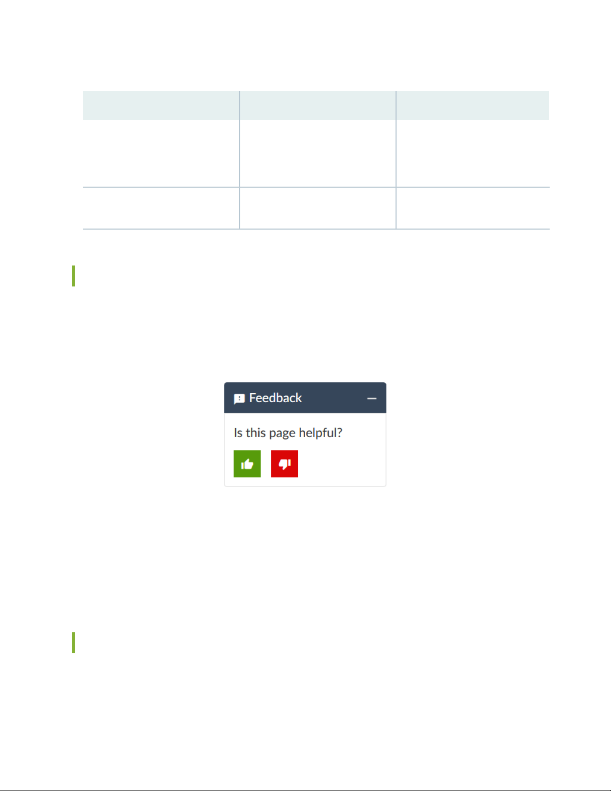
Table 2: Text and Syntax Conventions (continued)
ix
ExamplesDescriptionConvention
Bold text like this
> (bold right angle bracket)
Represents graphical user interface
(GUI) items you click or select.
Separates levels in a hierarchy of
menu selections.
In the Logical Interfaces box, select
•
All Interfaces.
To cancel the configuration, click
•
Cancel.
In the configuration editor hierarchy,
select Protocols>Ospf.
Documentation Feedback
We encourage you to provide feedback so that we can improve our documentation. You can use either
of the following methods:
Online feedback system—Click TechLibrary Feedback, on the lower right of any page on the Juniper
•
Networks TechLibrary site, and do one of the following:
Click the thumbs-up icon if the information on the page was helpful to you.
•
Click the thumbs-down icon if the information on the page was not helpful to you or if you have
•
suggestions for improvement, and use the pop-up form to provide feedback.
E-mail—Send your comments to techpubs-comments@juniper.net. Include the document or topic name,
•
URL or page number, and software version (if applicable).
Requesting Technical Support
Technical product support is available through the Juniper Networks Technical Assistance Center (JTAC).
If you are a customer with an active Juniper Care or Partner Support Services support contract, or are
Page 10

covered under warranty, and need post-sales technical support, you can access our tools and resources
online or open a case with JTAC.
JTAC policies—For a complete understanding of our JTAC procedures and policies, review the JTAC User
•
Guide located at https://www.juniper.net/us/en/local/pdf/resource-guides/7100059-en.pdf.
Product warranties—For product warranty information, visit https://www.juniper.net/support/warranty/.
•
JTAC hours of operation—The JTAC centers have resources available 24 hours a day, 7 days a week,
•
365 days a year.
Self-Help Online Tools and Resources
For quick and easy problem resolution, Juniper Networks has designed an online self-service portal called
the Customer Support Center (CSC) that provides you with the following features:
Find CSC offerings: https://www.juniper.net/customers/support/
•
Search for known bugs: https://prsearch.juniper.net/
•
x
Find product documentation: https://www.juniper.net/documentation/
•
Find solutions and answer questions using our Knowledge Base: https://kb.juniper.net/
•
Download the latest versions of software and review release notes:
•
https://www.juniper.net/customers/csc/software/
Search technical bulletins for relevant hardware and software notifications:
•
https://kb.juniper.net/InfoCenter/
Join and participate in the Juniper Networks Community Forum:
•
https://www.juniper.net/company/communities/
Create a service request online: https://myjuniper.juniper.net
•
To verify service entitlement by product serial number, use our Serial Number Entitlement (SNE) Tool:
https://entitlementsearch.juniper.net/entitlementsearch/
Creating a Service Request with JTAC
You can create a service request with JTAC on the Web or by telephone.
Visit https://myjuniper.juniper.net.
•
Call 1-888-314-JTAC (1-888-314-5822 toll-free in the USA, Canada, and Mexico).
•
For international or direct-dial options in countries without toll-free numbers, see
https://support.juniper.net/support/requesting-support/.
Page 11

1
CHAPTER
Virtual Appliance Overview
Junos Space Virtual Appliance Overview | 12
Ethernet Interfaces in a Junos Space Virtual Appliance Overview | 13
Page 12

Junos Space Virtual Appliance Overview
The Junos Space Virtual Appliance consists of preconfigured Junos Space Network Management Platform
software with a built-in operating system and application stack that is easy to deploy, manage, and maintain.
A Junos Space Virtual Appliance includes the same software and all the functionality available in a Junos
Space physical appliance. However, you must deploy the virtual appliance on a VMware ESX, VMWare
ESXi or KVM server, which provides a CPU, hard disk, RAM, and a network controller, but requires
installation of an operating system and applications to become fully functional.
Just as you can install additional physical appliances to create a fabric to provide scalability and availability,
you can deploy multiple virtual appliances to create a fabric that provides the same scalability and high
availability as a fabric of physical appliances.
A Junos Space fabric can contain only physical appliances ( JA2500), only virtual appliances, or a combination
of both physical and virtual appliances.
12
Configuring an NTP Time Source for Each Appliance Overview
To ensure consistent behavior among all nodes in a multinode fabric, the time on each node must be
synchronized with every other node in the fabric. When you configure the first Junos Space Virtual
Appliance with a Network Time Protocol (NTP) server, you must ensure that, if the first node (which is
used to synchronize time for all nodes in the fabric) goes down, all the other nodes in the fabric remain
synchronized. Additional nodes installed in the same fabric automatically get their time setting from the
first node in the fabric without any additional NTP server configuration.
NOTE: By default, Junos Space Network Management Platform synchronizes the local time
zone of the client computer with the time zone of the server so that the Web user interface
displays the Junos Space server time in the local time zone. However, the CLI server displays
time as per the time zone configured on the Junos Space server.
To ensure that time remains synchronized across all nodes in a fabric, we strongly recommend that you
add an NTP server to the first appliance (physical or virtual) during the initial setup.
NOTE: You must add the NTP server before you add the appliance or node to the fabric from
the Junos Space user interface.
Page 13

RELATED DOCUMENTATION
Junos Space Virtual Appliance Deployment Overview | 19
Configuring a Junos Space Virtual Appliance as a Junos Space Node | 41
Configuring a Junos Space Virtual Appliance as a Standalone or Primary FMPM Node | 68
Adding a Node to an Existing Junos Space Fabric | 139
Ethernet Interfaces in a Junos Space Virtual Appliance Overview
A Junos Space Virtual Appliance contains four Ethernet interfaces—eth0, eth1, eth2, and eth3. The Ethernet
interfaces eth0 and eth3 support both IPv4 and IPv6 addresses. As a separate IP address is available for
each IP stack, for any connection initiated by Junos Space, the source IP address (that is, the IPv4 or IPv6
address) of the connection is bound by the IP address type of a managed device. For a connection initiated
by a managed device, Junos Space listens on both IPv4 and IPv6 addresses of the device management
interface (eth3). Therefore, a managed device can communicate with Junos Space by using its IPv4 or IPv6
address.
13
NOTE: From Junos Space Network Management Platform Release 14.1R2 onward, you can
configure Junos Space Ethernet interfaces with only IPv4 addresses, or both IPv4 and IPv6
addresses.
Junos Space supports managed devices based on the IP address type (that is, the IPv4 or IPv6 address)
configured for the device management interface. You can configure an IPv4 or IPv6 address for the device
management interface. If the device management interface is not configured, the IP address type of the
node management interface (eth0) is considered for communication with managed devices.
Table 3 on page 14 details the support matrix for IPv4 and IPv6 address configurations on the device
management interface.
Page 14

Table 3: Matrix for IP Address Versions Supported on Devices
14
IP Address of
Managed Devices
Supported by Junos
Spaceeth3eth0
IPv6 AddressIPv4 AddressIPv6 AddressIPv4 Address
IPv4Not ConfiguredNot ConfiguredNot ConfiguredConfigured
IPv4 and IPv6Not ConfiguredNot ConfiguredConfiguredConfigured
IPv4Not ConfiguredConfiguredNot ConfiguredConfigured
IPv4 and IPv6ConfiguredConfiguredNot ConfiguredConfigured
IPv6ConfiguredNot ConfiguredNot ConfiguredConfigured
IPv4 and IPv6ConfiguredConfiguredConfiguredConfigured
You can use the Ethernet interfaces of Junos Space as follows:
eth0—Use the eth0 interface to configure the virtual IP (VIP) address of a fabric and the IP address of
•
the node as well as to access the managed devices. The VIP address and the IP address of the node
should be on the same subnet.
The eth0:0 subinterface provides access to the Junos Space Network Management Platform GUI. You
can access the GUI by using the VIP address of the fabric.
eth1—Use the eth1 interface as an administrative interface of a Junos Space node. Use SSH to access
•
a Junos Space node through this interface. The eth0 interface and the eth1 interface can be on different
subnets.
If you configure eth1, SSH stops running on the eth0 and the eth3 interfaces. You can access the CLI
of the Junos Space virtual appliance only through the eth1 interface.
NOTE: From Junos Space Network Management Platform Release 14.1R1 onward, you can
configure the eth1 Ethernet interface as an administrative interface.
eth2—The eth2 interface is reserved for future use.
•
eth3—Use the eth3 interface for SSH access to managed devices when the managed devices are on an
•
out-of-band management subnet or on a subnet not accessible through the eth0 interface.
Page 15

NOTE:
If the managed devices are not accessible through the default gateway, you must configure
•
static routes. Any static route configured manually is populated in the main routing table,
which is used to route traffic through the eth0 interface.
When the eth3 interface is configured as a device management interface, Junos Space
•
Platform does not forward ICMP packets through the eth3 interface. To allow ICMP packets
through the eth3 interface, routes must be added manually.
NOTE: When you configure a node as an FMPM node, you can use only the eth0 and eth1
interfaces.
When you configure an appliance as a Junos Space node, you can configure the Ethernet interfaces as
•
follows:
15
Configure only the eth0 interface.
•
When only Ethernet interface (eth0) is used, the Junos Space nodes in the fabric, virtual IP (VIP) address
of the fabric, and the devices being managed by Junos Space are on the same subnet.
Configure the eth0 and eth3 interfaces.
•
When Ethernet interfaces eth0 and eth3 are used, the Junos Space nodes in the fabric and VIP address
of the fabric are on the same subnet and are reachable through Ethernet interface eth0. The devices
being managed by Junos Space are on the same subnet, which is different from the one reachable
through Ethernet interface eth0, and are reachable through Ethernet interface eth3.
Configure the eth0 and eth1 interfaces.
•
When Ethernet interfaces eth0 and eth1 are used, the Junos Space nodes in the fabric and the VIP
address of the fabric may or may not be on the same subnet. The eth1 interface provides SSH access
to the Junos Space nodes.
The VIP address and the devices being managed by Junos Space are on the same subnet.
Configure the eth0, eth1, and eth3 interfaces.
•
When Ethernet interfaces eth0, eth1, and eth3 are used, the Junos Space nodes in the fabric and the
VIP address of the fabric may or may not be on the same subnet. The Junos Space nodes are reachable
(SSH access) only through the eth1 interface.
The managed devices can be reached through the eth0 interface if they are configured on the same
subnet as the VIP address; on any other subnet, the managed devices can be reached through the
eth3 interface.
Page 16

NOTE: If the managed devices are not reachable through the default gateway configured
for the eth3 interface, you must configure static routes for the eth3 interface. The eth3
interface refers to the devint routing table.
Any static route configured manually is populated in the main routing table, which is used
to route traffic through the eth0 interface.
When you configure an appliance as a specialized node used for fault monitoring and performance
•
monitoring (FMPM), you can use only the Ethernet interfaces eth0 and eth1.
Ethernet interface eth1 provides SSH access to FMPM nodes.
NOTE: For more information about the Junos Space fabric, refer to the Managing Nodes in the
Junos Space Fabric chapter in the Junos Space Network Management Platform Workspaces Feature
Guide (available at https://www.juniper.net/documentation/en_US/junos-space18.1/index.html).
16
Table 4 on page 16 summarizes the functions of Ethernet interfaces on the Junos Space Virtual Appliance.
Table 4: Junos Space Virtual Appliance Ethernet Interfaces
FunctionInterface
eth0
eth1
eth3
SSH and device management, if only the Ethernet interface ETH0 or
Ethernet interface 0 is used
GUI interfaceeth0:0
SSH access to the Junos Space nodes
NOTE: SSH is disabled on the eth0 and eth3 interfaces when eth1 is
configured.
Reserved for future useeth2
Device management when managed devices are on an out-of-band
management subnet and not reachable by the Ethernet interface eth0
RELATED DOCUMENTATION
Configuring a Junos Space Virtual Appliance as a Junos Space Node | 41
Page 17

Configuring a Junos Space Virtual Appliance as a Standalone or Primary FMPM Node | 68
Changing the Network and System Settings of a Junos Space Virtual Appliance | 87
17
Page 18

2
CHAPTER
Deploying the Junos Space Virtual
Appliance
Junos Space Virtual Appliance Deployment Overview | 19
Deploying a Junos Space Virtual Appliance on a VMware ESXi Server | 20
Deploying a Junos Space Virtual Appliance on a KVM Server | 25
Adding Disk Resources for a Junos Space Virtual Appliance | 30
Starting Open VM Tools in Junos Space Platform | 34
Installing VI Toolkit for Perl on Junos Space Virtual Appliance | 37
Page 19

Junos Space Virtual Appliance Deployment Overview
The Junos Space Virtual Appliance is distributed in the Open Virtualization Appliance (OVA) and qcow2
formats.
You can deploy the Junos Space Virtual Appliance *.ova file on a VMware ESXi server version 5.5, 6.0, or
6.5 and the *.qcow2 on a Kernel-based Virtual Machine (KVM) server. The Junos Space Virtual Appliance
Release 16.1R1 and later can be deployed on qemu-kvm (KVM) Release 1.5.3-105.el7 or later which runs
on CentOS Release 7.2. From Junos Space Network Management Platform Release 18.2 onward, Junos
Space Virtual Appliance will be installed with VM Hardware version 8.
NOTE: Though a KVM server on other Linux distributions is supported, we recommend that
you use KVM on CentOS.
19
After the Junos Space Virtual Appliance is deployed, you can use the VMware vSphere client or Virtual
Machine Manager (VMM) to connect to the VMware ESX (or VMware ESXi ) server or KVM server
respectively and configure the Junos Space Virtual Appliance.
The minimum hardware requirements for deploying a Junos Space Virtual Appliance are as follows:
64-bit quad processor with a clock speed of at least 2.66 GHz
•
Four virtual CPUs
•
1-Gbps network
•
32-GB RAM to configure the virtual appliance as a Junos Space node or fault monitoring and performance
•
monitoring (FMPM) node
NOTE: 64-GB RAM is required if the number of rules per firewall (SRX) cluster is more than
6000 and if firewall policies of similar sizes are being concurrently published.
500-GB hard disk
•
Ensure that 100-GB free disk space is available if the Junos Space Virtual Appliance is to be configured
as a FMPM node. For information about adding disk resources, refer to “Adding Disk Resources for a
Junos Space Virtual Appliance” on page 30.
1-TB hard disk if you are configuring Database nodes
•
Configure Open VM tools (see “Starting Open VM Tools in Junos Space Platform” on page 34 for details.)
•
Page 20

NOTE:
We recommend that you use disks with I/O speed of 200 MBps or above. For information
•
about determining I/O speed of a disk used in the node of a Junos Space cluster, see How do
I Determine the Disk I/O Speed of a Node in the Junos Space Fabric? in the Junos Space Hardware
and Virtual Appliances FAQ.
We recommend against cloning a deployed Junos Space Image and using it as another instance
•
of a Junos Space Virtual Appliance.
RELATED DOCUMENTATION
Deploying a Junos Space Virtual Appliance on a VMware ESXi Server | 20
Deploying a Junos Space Virtual Appliance on a KVM Server | 25
Adding Disk Resources for a Junos Space Virtual Appliance | 30
20
Deploying a Junos Space Virtual Appliance on a VMware ESXi Server
The Junos Space Virtual Appliance requires a VMware ESXi server 5.5, 6.0, 6.5, or 6.7 that can support a
virtual machine with the following configuration:
NOTE:
The ESXi host server must include a Standard or Enterprise edition license, which may not be
•
installed on the host server by default.
VMware VMotion is supported for moving Junos Space Virtual Appliances from one VMware
•
ESXi server to another VMware ESXi server.
For information about the minimum hardware requirements for deploying a Junos Space Virtual Appliance,
see “Junos Space Virtual Appliance Deployment Overview” on page 19.
Page 21

BEST PRACTICE: We recommend the following best practices after you deploy the Junos Space
Virtual Appliance on a VMWare ESXi server:
VMWare ESXi server snapshots should be taken after shutting down Junos Space servers.
•
Ensure snapshots are taken simultaneously across all the nodes in the fabric.
To ensure optimal performance of Junos Space, configure purging policies for the VMWare
•
host one month after the Junos Space fabric is functional.
The deployment of a Junos Space Virtual Appliance on a VMware ESXi server includes the following tasks:
1.
Installing the VMware ESXi Server | 21
2.
Installing a Junos Space Virtual Appliance on a VMware ESXi Server | 22
3.
Modifying RAM Settings for a Junos Space Virtual Appliance | 24
4.
Adding Disk Resources for a Junos Space Virtual Appliance | 25
21
Installing the VMware ESXi Server
To install the VMware ESXi server:
1. Download the VMware ESXi server installation package from https://www.vmware.com/download/vi/.
2. Install the VMware ESXi server.
For instructions to install the VMware ESXi server, go to
https://www.vmware.com/support/pubs/vi_pubs.html.
NOTE: You can install the VMware vSphere Client when you install the VMware ESXi server
5.5, 6.0, or 6.5. Contact VMware for support with installing ESXi server.
NOTE: Junos Space Network Management Platform is not certified to be used with VMware
tools.
Page 22

Installing a Junos Space Virtual Appliance on a VMware ESXi Server
IN THIS SECTION
Installing a Junos Space Virtual Appliance by Using vSphere Client | 22
Installing a Junos Space Virtual Appliance by Using the OVF Tool | 23
You can use vSphere Client 4.0 or later or OVF Tool 2.01 or later to deploy the Junos Space Virtual
Appliance image on a VMWare ESXi server.
Installing a Junos Space Virtual Appliance by Using vSphere Client
To create a Junos Space Virtual Appliance by using vSphere Client 4.0:
22
1. Download the Junos Space Virtual Appliance image from
https://www.juniper.net/support/downloads/?p=space#sw to your local system.
NOTE: Do not change the name of the Junos Space Virtual Appliance image file that you
download from the Juniper Networks support site. If you change the name of the image file,
the creation of the Junos Space Virtual Appliance can fail.
2. Launch the vSphere Client that is connected to the ESXi server where the Junos Space Virtual Appliance
is to be deployed.
3. Select File > Deploy OVF Template from the menu bar.
The Deploy OVF Template page appears.
4. Click the Deploy from file option and click Browse, and then upload the OVA file from your storage
location.
NOTE: You can use the same image to deploy both Junos Space and fault monitoring and
performance monitoring (FMPM) nodes.
5. Click Next.
Page 23

6. Verify the OVF Template details and then click Next.
7. Specify a name and location for the deployed template and then click Next.
A template name can contain a maximum of 80 characters. Template names are not case-sensitive.
8. Verify your settings and then click Finish to create the Junos Space Virtual Appliance.
Installing a Junos Space Virtual Appliance by Using the OVF Tool
Before you use the OVF Tool to create a Junos Space Virtual Appliance, ensure that the OVF Tool is
installed on the system where you save the Junos Space Virtual Appliance image file (*.ova).
To create a Junos Space Virtual Appliance by using the OVF Tool:
1. Download the Junos Space Virtual Appliance image from
https://www.juniper.net/support/downloads/?p=space#sw to your local system.
23
NOTE: Do not change the name of the Junos Space Virtual Appliance image file that you
download from the Juniper Networks support site. If you change the name of the image file,
the creation of the Junos Space Virtual Appliance can fail.
2. Log in to the local system and navigate to the location where the Junos Space Virtual Appliance image
file is saved.
3. Run the following command:
/usr/bin/ovftool/ovftool --name=virtual-appliance image-file
vi://username:password@host-id
where:
virtual-appliance is the name you assign to the Junos Space Virtual Appliance.
•
image-file is the name of the Junos Space Virtual Appliance image file.
•
username is the username of the host machine where you deploy the Junos Space Virtual Appliance.
•
password is the password of the host machine where you deploy the Junos Space Virtual Appliance.
•
host-id is the IP address of the host machine where you deploy the Junos Space Virtual Appliance.
•
Example:
Page 24

/usr/bin/ovftool/ovftool -name=space1vm space-19.3R1.0.ova
vi://username:password@10.157.10.1
The Junos Space Virtual Appliance is deployed on the host machine.
4. Log in to the host machine and edit the settings (number of processors, memory) of the Junos Space
Virtual Appliance. For information about editing the settings of a Junos Space Virtual Appliance by
using the OVF Tool, see the OVF Tool documentation at
https://www.vmware.com/support/developer/ovf/ .
Modifying RAM Settings for a Junos Space Virtual Appliance
To add RAM for a Junos Space Virtual Appliance:
24
1. Launch the VMware vSphere Client and log in to the ESXi server where the Junos Space Virtual Appliance
is deployed.
2. Select the Junos Space Virtual Appliance from the inventory view.
3. If the Junos Space Virtual Appliance is powered on, you must power off the appliance to configure
RAM.
To power off the Junos Space Virtual Appliance, right-click the Junos Space Virtual Appliance icon and
select Power > Power Off.
4. Select the Summary tab to view the Junos Space virtual machine settings.
5. Select Edit Settings to view and edit the virtual memory settings.
6. Select Memory.
7. Update the RAM to 32 GB to operate the Junos Space Virtual Appliance as a Junos Space node or as
an FMPM node.
8. Click OK.
RAM is added to the Junos Space Virtual Appliance.
Page 25

Adding Disk Resources for a Junos Space Virtual Appliance
For information about adding disk resources for Junos Space Virtual Appliance, see “Adding Disk Resources
for a Junos Space Virtual Appliance” on page 30.
RELATED DOCUMENTATION
Configuring a Junos Space Virtual Appliance as a Junos Space Node | 41
Configuring a Junos Space Virtual Appliance as a Standalone or Primary FMPM Node | 68
Configuring a Junos Space Virtual Appliance as a Backup or Secondary FMPM Node for High
Availability | 79
Adding a Node to an Existing Junos Space Fabric | 139
Viewing Nodes in the Fabric | 148
25
Deploying a Junos Space Virtual Appliance on a KVM Server
The Junos Space Virtual Appliance Release 16.1R1 and later can be deployed on qemu-kvm (KVM) Release
1.5.3 or later.
NOTE: Juniper Networks does not provide any support for installing and configuring the KVM
server. You must install the virtual appliance image and configure it as per the recommended
specifications for the virtual appliance. Juniper Networks will provide support only after the
Junos Space Virtual Appliance has booted successfully.
The prerequisites to deploy a Junos Space Virtual Appliance on a KVM server are as follows:
Knowledge about configuring and installing a KVM server.
•
KVM server and supported packages must be installed on your Linux-based system. Contact your Linux
•
vendor or documentation for information about installing KVM.
An application or method to view the remote system virtual monitor, such as Virtual Machine Manager
•
(VMM), Virtual Network Computing (VNC) Viewer, or any other application.
Bridge Interface configured according to your environment and at least two free static IP addresses.
•
Page 26

For information about the minimum hardware requirements for deploying a Junos Space Virtual Appliance,
see “Junos Space Virtual Appliance Deployment Overview” on page 19.
The deployment of a Junos Space Virtual Appliance on a KVM server by using VMM includes the following
tasks:
NOTE: Though deploying the Junos Space Virtual Appliance on the KVM server by using virtual
machine clients other than VMM is possible, Juniper Networks does not provide support for
installing the Junos Space Virtual Appliance using clients other than VMM.
1.
Installing a Junos Space Virtual Appliance on the KVM Server by Using VMM | 26
2.
Modifying the Type of Virtual Disk Interface | 28
3.
Modifying RAM for a Junos Space Virtual Appliance | 29
4.
Adding Disk Resources for a Junos Space Virtual Appliance | 29
5.
Enabling Multicast on Bridged Interfaces of a KVM-Host Machine | 29
26
Installing a Junos Space Virtual Appliance on the KVM Server by Using VMM
Use the VMM virtual machine client to install the Junos Space Virtual Appliance on a KVM server.
To install the Junos Space Virtual Appliance on a KVM server by using VMM:
1. Download the Junos Space Virtual Appliance image from
https://www.juniper.net/support/downloads/?p=space#sw to your local system.
NOTE: Do not change the name of the Junos Space Virtual Appliance image file that you
download from the Juniper Networks support site. If you change the name of the image file,
the creation of the Junos Space Virtual Appliance can fail.
2. Launch the VMM client.
3. Select File > New Virtual Machine on the menu bar of VMM to install a new virtual machine on a KVM
server.
The New VM dialog box appears and displays Step 1 of 4 of the New VM installation.
Page 27

4. Under Choose how you would like to install the operating system, click Import existing disk image.
5. Click Forward to go to the next step.
Step 2 of 4 is displayed.
6. Under Provide the existing storage path, click Browse.
7. Under Choose storage volume , click Browse Local at the bottom of the dialog box to locate and select
the Junos Space Virtual Appliance image file (.qcow2) saved on your system.
8. Under Choose an operating system type and version, select Linux for OS type and Red Hat Enterprise
Linux version number for Version.
NOTE: We recommend to use the same Linux version as Junos Space Platform is using.
27
9. Click Forward to go to the next step.
Step 3 of 4 is displayed.
10. Under Choose Memory and CPU settings, ensure that 4 is set for CPUs and select or enter the following
value for Memory (RAM):
32768 MB–For the Junos Space Virtual Appliance to be deployed as a Junos Space node or as an
•
FMPM node
11. Click Forward to go to the next step.
Step 4 of 4 is displayed.
12. Under Ready to begin the installation, in the Name field, enter a name for the Junos Space Virtual
Appliance.
13. Under Network selection, select the options based on how you want to configure network
communication on the Junos Space Platform setup.
14. Click Finish.
The New VM dialog box closes. The Junos Space Virtual Appliance is started and the console is displayed.
The Junos Space Virtual Appliance is created and listed with the name that you entered in the VMM.
Page 28

Modifying the Type of Virtual Disk Interface
After the Junos Space Virtual Appliance is created, you must change the hard disk interface type to
Integrated Drive Electronics (IDE) to avoid any issues with the booting up of the Junos Space Virtual
Appliance due to kernel panic.
NOTE: If you are using CLI of VMM to set up KVM, you set the type of virtual disk interface to
IDE at the start of the set up. You do not have to reset the type of interface again.
To change the hard disk interface type to IDE:
1. Select the Junos Space Virtual Appliance just created and select Edit > Virtual Machine Details on the
menu bar of VMM to edit the hardware settings.
2. Click the Show virtual hardware details icon in the Virtual Machine Details dialog box.
28
3. Click VirtIO Disk1 (Virtual Disk) on the left of the dialog box to change the type of the disk interface
to IDE.
The details of the Virtual disk is displayed on the right of the dialog box.
4. Under Advanced Options, select IDE for Disk Bus and qcow2 for Storage format.
5. Click Apply.
6. (Optional) To apply the changes immediately, shut down and restart the virtual appliance if the Junos
Space Virtual Appliance is already powered on.
To restart the Junos Space Virtual Appliance:
a. Right-click the Junos Space Virtual Appliance icon and select Shutdown > Power Off, to shut down
the Junos Space Virtual Appliance.
b. Select the Junos Space Virtual Appliance icon and click the Power on the virtual machine icon to
start the Junos Space Virtual Appliance. Alternatively, you can right-click the Junos Space Virtual
Appliance icon and select Run.
Page 29

Modifying RAM for a Junos Space Virtual Appliance
The Junos Space Virtual Appliance file is distributed with 8 GB of RAM and four virtual CPUs. You need
32-GB RAM to configure the Junos Space Virtual Appliance as a Junos Space node or as an FMPM node.
To modify RAM for the Junos Space Virtual Appliance:
1. Launch VMM and select the Junos Space Virtual Appliance for which you want to modify RAM.
2. (Optional) If the Junos Space Virtual Appliance is running, you must shut down the appliance to modify
RAM.
To shut down the Junos Space Virtual Appliance, right-click the Junos Space Virtual Appliance icon
and select Shutdown > Power Off.
3. To view and change RAM allocated to the Junos Space Virtual Appliance, select Edit > Virtual Machine
Details on the menu bar of VMM to edit the hardware settings.
29
4. Click the Show virtual hardware details icon in the Virtual Machine Details dialog box.
5. Click Memory on the left side of the dialog box.
The RAM details of the virtual machine is displayed on the right of the dialog box.
6. Enter the required memory in the Current allocation and Maximum allocation fields.
7. Click Apply to modify the RAM allocation.
Adding Disk Resources for a Junos Space Virtual Appliance
For information about adding disk resources for Junos Space Virtual Appliance, see “Adding Disk Resources
for a Junos Space Virtual Appliance” on page 30.
Enabling Multicast on Bridged Interfaces of a KVM-Host Machine
For creating Junos Space clusters, multicast must be enabled on the bridged interface of a KVM-host
machine on which Junos Space node is deployed to allow multicast traffic to flow between the nodes of
the cluster.. If Junos Space nodes in a cluster are deployed on different host machines, multicast must be
enabled on the bridged interface of each host machine.
Page 30

To configure multicast on a bridged interface of a KVM-host machine, log in to the KVM-host machine
after the UI of the Junos Space node is up and execute the ifconfig InterfaceName allmulti command,
where InterfaceName is the name of the interface.
Example:
-bash-4.1$ ifconfig macvtap0 allmulti
NOTE: Configure multicast on all the KVM-host machines before adding a Junos Space node
to a cluster.
RELATED DOCUMENTATION
30
Configuring a Junos Space Virtual Appliance as a Junos Space Node | 41
Configuring a Junos Space Virtual Appliance as a Standalone or Primary FMPM Node | 68
Configuring a Junos Space Virtual Appliance as a Backup or Secondary FMPM Node for High
Availability | 79
Adding a Node to an Existing Junos Space Fabric | 139
Viewing Nodes in the Fabric | 148
Adding Disk Resources for a Junos Space Virtual Appliance
IN THIS SECTION
Adding Disk Resources for a Junos Space Virtual Appliance Deployed on a VMware ESX or VMware ESXi
Server | 32
Adding Disk Resources for a Junos Space Virtual Appliance Deployed on a KVM Server | 33
The Junos Space Virtual Appliance files are distributed with 250-GB of disk space.
Page 31

NOTE:
The free space available in all the partitions should be monitored periodically and the available
•
free disk space increased if required. The /var and /var/log partitions should be monitored
more frequently as most of the data are stored in these partitions and space utilization is high.
For information about disk space needed for installing a Junos Space application, refer to the
respective application documentation available at Junos Space Software, Release 18.3.
If you are expanding the disk space of nodes in a Junos Space fabric (cluster) comprising virtual
•
appliances, you must first expand the disk space of the virtual IP (VIP) node and ensure that
the VIP node has come up, that is, JBoss and MySQL services are up before expanding the
disk space of other nodes in the fabric; otherwise, the fabric may become unstable and the
Junos Space GUI inaccessible.
While configuring a Junos Space Virtual Appliance as a Junos Space node or an FMPM node,
•
it is recommended that you allocate disk space partitions as per the disk space allocations for
a JA2500 Junos Space Appliance. However, you can allocate less or more space to disk partitions
as per your requirement. For more information about disk space allocation in JA2500 Junos
Space Appliance, see Configuring a Junos Space Appliance as a Junos Space Node.
31
To allocate additional disk space for partitions, add a disk resource and expand a partition one at a time.
The free space available on the disk resource can be shared among the different partitions. For example,
to expand the /var and /var/log partitions by 20 GB each, add a disk resource of minimum 40 GB. Expand
the drive size of the /var partition by 20 GB and then expand the /var/log partition by 20 GB.
Table 5 on page 31 specifies the data stored in the partitions of a Junos Space Node and an FMPM node.
Table 5: Data Stored in the Partitions of a Junos Space Node and an FMPM Node
FMPM NodeJunos Space NodePartition
/var
MySQL database, PostgreSQL database, database
backup file, and disaster recovery data files
FMPM data, MySQL database,
PostgreSQL database
All system log filesAll system log files/var/log
Temporary filesTemporary files/tmp
OpenNMS installationWorldwide adapters, JBoss configuration files/
The following tasks that must be performed for adding disk resources are explained in this topic:
Page 32

Adding Disk Resources for a Junos Space Virtual Appliance Deployed on a VMware ESX or VMware ESXi Server
The Junos Space Virtual Appliance file is distributed with 250 GB of disk space. You can increase the hard
disk size based on the requirement for the specific Junos Space deployment. The following procedure
describes how you can add disk resources for a Junos Space Virtual Appliance deployed on a VMware ESX
or VMware ESXi Server.
To add disk resources for the Junos Space Virtual Appliance:
1. In the VMware vSphere Client, right-click the Junos Space Virtual Appliance icon and select Power >
Power On. The Junos Space Virtual Appliance must be powered on to add disk resources.
2. Right-click the Junos Space Virtual Appliance icon and select Edit Settings.
The Virtual Machine Properties page is displayed.
32
3. Select the Hardware tab and click Add.
The Device Type page is displayed.
4. Under Choose the type of disk you wish to add, select Hard Disk.
5. Click Next.
The Select a Disk page appears.
6. Under Disk, select Create a new Virtual disk.
7. Click Next.
The Create a Disk page appears.
8. Under Capacity, set the Disk Size field to the recommended size for the partition that you want to
expand.
Under Location, retain the default setting—that is, leave the Store with the virtual machine selected.
9. Click Next.
The Advanced Options page is displayed.
10. Leave the default settings unchanged and click Next.
The Ready to Complete page is displayed.
Page 33

11. Review your selected options and click Finish.
The Virtual Machine Properties page displays the new virtual disk on the Hardware list.
12. Click OK to create the new virtual disk.
A status bar shows the progress at the bottom of the page.
The next step is to configure the basic settings for your deployed Junos Space Virtual Appliance. To
configure basic settings for the appliance, access the console in the VMware vSphere Client.
NOTE: After the new virtual disk is created, the Junos Space Virtual Appliance must be scanned
to detect the additional disk space that you added. To start the scan for additional disk space,
select the Expand VM Drive Size option from the Junos Space Settings Menu immediately after
you configure the basic settings for your Junos Space Virtual Appliance.
For information about expanding the drive size, refer to “Configuring a Junos Space Virtual
Appliance as a Junos Space Node” on page 41.
33
Adding Disk Resources for a Junos Space Virtual Appliance Deployed on a KVM Server
The Junos Space Virtual Appliance file is distributed with 250 GB of disk space. You can increase the size
of the hard disk based on the requirement for the specific Junos Space deployment. The following procedure
describes how you can add disk resources for a Junos Space Virtual Appliance deployed on a KVM Server.
To add disk resources for the Junos Space Virtual Appliance:
1. Launch VMM and select the Junos Space Virtual Appliance for which you want to modify the disk
space.
2. Select Edit > Virtual Machine Details on the menu bar of VMM to edit the hardware settings.
3. Click the Show virtual hardware details icon in the Virtual Machine Details dialog box.
4. Click Add Hardware at the bottom left of the dialog box.
The Add New Virtual Hardware dialog box is displayed.
Page 34

5. Click Storage, select Create a disk image for the virtual machine, and enter the required disk space in
the box.
6. Select IDE for Bus Type.
7. Click Finish.
You can see the newly-added disk listed in the left pane.
8. (Optional) If the Junos Space Virtual Appliance is already powered on, shut down and restart the Virtual
appliance.
To restart the Junos Space Virtual Appliance:
a. Right-click the Junos Space Virtual Appliance icon and select Shutdown > Power Off, to shut down
the Junos Space Virtual Appliance.
b. Select the Junos Space Virtual Appliance icon and click the Power on the virtual machine icon to
start the Junos Space Virtual Appliance. Alternatively, you can right-click the Junos Space Virtual
Appliance icon and select Run.
34
RELATED DOCUMENTATION
Changing the Network and System Settings of a Junos Space Virtual Appliance | 87
Configuring a Junos Space Virtual Appliance as a Junos Space Node | 41
Configuring a Junos Space Virtual Appliance as a Standalone or Primary FMPM Node | 68
Configuring a Junos Space Virtual Appliance as a Backup or Secondary FMPM Node for High
Availability | 79
Starting Open VM Tools in Junos Space Platform
Junos Space Network Management Platform Release 16.1R1 supports the use of Open VM Tools to
facilitate better management and the seamless interaction of the VMware ESXi 6.0 server with the Junos
Space Virtual Appliance.
Page 35

Install Open VM Tools in Junos Space Platform:
1. Download the tarball files related to Open VM tools to Junos Space server/home/admin directory.
2. Extract the <file-name>.tgz files for Open VM tools using the tar-<file-name>.tgz command.
3. Change the directory to cd open-vm-tools.
4. Install the Open VM Tool using rpm -ivh open-vm-tools/open-vm-tools-10.1.5-6.el6.x86_64.rpm
command.
NOTE: Before you start Open VM Tools in Junos Space Platform, ensure that you have installed
Open VM Tools 10.1.5 on the Junos Space Virtual Appliance.
You need the following utilities and drivers to build the Open VM Tools—xmlsec1,
xmlsec1-openssl, libmspack, libdnet, libicu, fuse-libs, and fuse. Download these utilities and
drivers from https://fedoraproject.org/wiki/EPEL or
https://dl.fedoraproject.org/pub/epel/6/x86_64/Packages/o/open-vm-tools-10.1.5-6.el6.x86_64.rpm.
35
To start Open VM Tools in Junos Space Platform:
1. Log in to the Junos Space Virtual Appliance as the admin user.
The Junos Space Settings menu is displayed.
2. Type 7 to access the shell.
You are prompted to enter the administrator password.
3. Type the administrator password and press Enter.
The shell prompt appears, as shown in the following example:
[user@host ~]#
4. Type the /usr/bin/vmtoolsd & command at the shell prompt and press Enter:
[user@host ~]# /usr/bin/vmtoolsd &
The Open VM Tools service is started on the node.
Page 36

NOTE: To start Open VM Tools each time the Junos Space node is rebooted, add the
/usr/bin/vmtoolsd & command to the /etc/rc.local file.
Release History Table
36
DescriptionRelease
16.1R1
Junos Space Network Management Platform Release 16.1R1 supports the use of Open VM
Tools to facilitate better management and the seamless interaction of the VMware ESXi 6.0
server with the Junos Space Virtual Appliance
RELATED DOCUMENTATION
Junos Space Virtual Appliance Deployment Overview | 19
Page 37

Installing VI Toolkit for Perl on Junos Space Virtual Appliance
You can install VMware Infrastructure Toolkit (VI Toolkit) on a Junos Space virtual appliance deployed on
a VMware Elastic Sky X (ESX) server or an ESXi server to enable the System Snapshot feature in Junos
Space Network Management Platform.
The System Snapshot feature enables you to create a snapshot of the system state and roll back the system
to a predefined state.
NOTE: If you have a fabric consisting of only virtual appliances, then VI Toolkit for Perl must be
installed on all nodes of the fabric for the System Snapshot functionality to be enabled on Junos
Space Platform.
37
To install VI Toolkit for Perl on a Junos Space virtual appliance deployed on an ESX or an ESXi server:
1. Open https://www.vmware.com/support/developer/viperltoolkit/ in a web browser.
The VMware vSphere SDK for Perl Documentation page is displayed.
2. Select the release VI Perl Toolkit 1.6 from the drop-down list.
3. Click the Download link.
You are redirected to the VMware login page.
4. If you are not a registered user, click Register.
You are redirected to the registration page. Follow the prompts on the registration page and activate
your account.
5. Log in using your VMware credentials.
The VMware Infrastructure Perl Toolkit page opens, displaying a list of different packages of VI Perl
Toolkit 1.6.
6. From the list, click the Download Now button for the VMware-VIPerl-1.6.0-104313.x86_64.tar.gz (VI
Perl Toolkit - Linux Installer for 64-bit) package.
The End User License Agreement dialog box is displayed.
7. Follow the prompts displayed on the page to download the file.
Page 38

The VMware-VIPerl-1.6.0-104313.x86_64.tar.gz file is downloaded to your local computer.
8. Connect to the Junos Space node (by using SSH) and log in (as the admin user) to access the Junos
Space CLI.
9. Open a debug (command) prompt by using the Junos Space Settings menu.
10. Create a new directory named jmp-vm by executing the following command:
mkdir /usr/local/jmp-vm
11. Copy the VMware-VIPerl-1.6.0-104313.x86_64.tar.gz file you downloaded to the directory
/usr/local/jmp-vm.
12. Change the current directory to /usr/local/jmp-vm by executing the following command:
cd /usr/local/jmp-vm
38
13. Extract the compressed TAR files by executing the following command:
tar -zxvf *.gz
14. Create a new directory named etc within the folder vmware-viperl-distrib by executing the following
command:
mkdir /usr/local/jmp-vm/vmware-viperl-distrib/etc
15. Copy the file vmware-uninstall-viperl.pl from the directory /var/www/cgi-bin to the directory named
/usr/local/jmp-vm/vmware-viperl-distrib/bin on the local machine by using the following command:
cp /var/www/cgi-bin/vmware-uninstall-viperl.pl
/usr/local/jmp-vm/vmware-viperl-distrib/bin/vmware-uninstall-viperl.pl
The following message is displayed:
cp: overwrite /usr/local/jmp-vm/vmware-viperl-distrib/bin/vmware-uninstall-viperl.pl?
16. Type yes to replace the existing vmware-uninstall-viperl.pl file and press Enter.
17. Change the permissions of the files in the /usr/local/jmp-vm folder to allow read and execute
permissions to everyone and, additionally, write permission to the file owner by executing the following
command:
chmod -R 755 /usr/local/jmp-vm
18. Run the file vmware-install.pl by executing the following command:
Page 39

perl vmware-viperl-distrib/vmware-install.pl --prefix=1
On successful installation, the following message is displayed:
The installation of VMware VIPerl Toolkit 1.6.0 build-104313 for Linux completed successfully. You
can decide to remove this software from your system at any time by invoking the following command:
"1/bin/vmware-uninstall-viperl.pl"
19. Log out of the Junos Space VIP node.
You can now create a System Snapshot by going to the Fabric page (Administration > Fabric). For more
information, see Creating a System Snapshot.
RELATED DOCUMENTATION
Creating a System Snapshot
Junos Space Virtual Appliance Deployment Overview | 19
39
Configuring a Junos Space Virtual Appliance as a Junos Space Node | 41
Page 40

3
CHAPTER
Configuring the Junos Space Virtual
Appliance
Configuring a Junos Space Virtual Appliance as a Junos Space Node | 41
Configuring a Junos Space Virtual Appliance as a Standalone or Primary FMPM
Node | 68
Configuring a Junos Space Virtual Appliance as a Backup or Secondary FMPM Node
for High Availability | 79
Changing the Network and System Settings of a Junos Space Virtual Appliance | 87
Page 41

Configuring a Junos Space Virtual Appliance as a Junos Space Node
After you deploy a Junos Space Virtual Appliance on a VMware ESX, VMware ESXi, or Kernel-based Virtual
Machine (KVM) server, you must enter basic network and machine information to make your Junos Space
Virtual Appliance accessible on the network. You must also add disk space to the partitions of the Junos
Space Virtual Appliance.
NOTE:
From Junos Space Network Management Platform Release 14.1R2 onward, you can configure
•
Junos Space Ethernet interfaces with only IPv4 addresses, or both IPv4 and IPv6 addresses.
From Junos Space Network Management Platform Release 16.1R1 onward, you can configure
•
access to Junos Space through a Network Address Translation (NAT) gateway.
41
Before you begin, ensure that you have the following information available:
IPv4 address and subnet mask for the node management (eth0) Ethernet interface
•
(Optional) IPv6 address and prefix for the eth0 Ethernet interface
•
IPv4 address of the default gateway for the eth0 Ethernet interface
•
(Optional) IPv6 address of the default gateway for the eth0 Ethernet interface
•
IPv4 address of the name server
•
(Optional) IPv6 address of the name server
•
(Optional) IPv4 address and subnet mask for the Ethernet interface eth3, if you are configuring a device
•
management interface.
NOTE: When you configure the eth3 interface as the device management interface, the IP
addresses of the eth0 and eth3 Ethernet interfaces must be in different subnets.
(Optional) IPv4 address of the default gateway for the eth3 Ethernet interface
•
NOTE: If you configure the IPv4 address for the eth3 Ethernet interface, you must configure
the IPv4 address of the default gateway.
(Optional) IPv6 address and prefix for the eth3 Ethernet interface
•
Page 42

(Optional) IPv6 address of the default gateway for the eth3 Ethernet interface
•
NOTE: If you configure the IPv6 address for the eth3 Ethernet interface, you must configure
the IPv6 address of the default gateway for the eth3 interface.
Virtual IP (VIP) address in IPv4 and IPv6 formats
•
The IPv4 format of the VIP address is used for accessing the Junos Space Network Management Platform
GUI through a Web browser. This IP address must be in the same subnet as the IP address assigned to
the eth0 Ethernet interface
The IPv6 format of the VIP address is used for receiving SNMP traps from managed devices.
IPv4 address or URI of the NTP source to synchronize time
•
(Optional) IPv4 address of the eth1 Ethernet interface
•
If the IP address of the eth1 interface is not in the same subnet as the VIP address, ensure that you have
the subnet mask and the default gateway for the eth1 interface.
42
(Optional) IPv4 address for the NAT outbound SSH
•
(Optional) IPv6 address for the NAT outbound SSH
•
(Optional) IPv4 port number for the NAT outbound SSH
•
(Optional) IPv6 port number for the NAT outbound SSH
•
(Optional) IPv4 address for the NAT trap
•
(Optional) IPv6 address for the NAT trap
•
(Optional) IPv4 port number for the NAT trap
•
(Optional) IPv6 port number for the NAT trap
•
This topic discusses the following tasks:
Configuring a Junos Space Virtual Appliance | 43
Configuring Access to Junos Space Through a NAT Gateway | 60
Configuring the eth1 Ethernet Interface | 66
Page 43

Configuring a Junos Space Virtual Appliance
You can configure a Junos Space Virtual Appliance as the first or standalone node in a cluster or add the
node to an existing cluster.
To configure a Junos Space Virtual Appliance:
1. Using a virtual machine client (such as VMware vSphere Client or Virtual Machine Manager [VMM]),
log in and power on the Junos Space Virtual Appliance.
2. Access the console on the virtual machine client to view the Junos Space login prompt.
3. At the Junos Space login prompt, type admin as your default login name and press Enter.
space-node login:admin
Password:
43
You are prompted to enter the administrator password.
4. Type abc123 as the default administrator password and press Enter.
Junos Space prompts you to change your default password.
5. To change the default password, do the following:
Type the default password and press Enter.
•
Type your new password and press Enter.
•
Retype your new password and press Enter.
•
If the password is changed successfully, the following message is displayed.
passwd: all authentication tokens updated successfully
Page 44

NOTE: You can choose a password that is at least eight characters long and contains characters
from at least three of the following four character classes: uppercase letters, lowercase letters,
numbers (0 through 9), and special characters.
However, if a password satisfies the preceding criteria but contains only a single uppercase
letter at the beginning or only a single number at the end, then that password is considered
invalid. For example, Abcdwip9, Qc9rdiwt, and bRfjvin9 are invalid passwords, but
AAbcdwip99, Qc9rdiwtQ, and bRfjvin99 are valid passwords.
Alternatively, instead of using a string of characters, you can choose a passphrase that is
between 16 and 40 characters long and contains at least three dictionary words separated
by at least one special character. For example, big#three;fork (14 characters long) and
circlefaceglass (no special characters) are invalid passphrases, but @big#three;fork& and
circle;face;glass are valid passphrases.
Passwords and passphrases are case-sensitive.
44
6. Enter the new password to log in to Junos Space.
7. Type S to install the virtual appliance as a Junos Space node.
This Junos Space node can be installed as one of the following:
(S)pace Platform
Full functionality. Every Junos Space Installation requires at least one Space
node.
(F)MPM
Specialized to fault and performance monitoring only. This requires at least
one Space node.
Choose the type of node to be installed [S/F] S
8. Configure the IP address for the eth0 interface.
Configuring Eth0:
1> Configure IPv4
2> Configure Both IPv4 and IPv6
Page 45

R> Redraw Menu
Choice [1-2,R]:
To configure the IPv4 address of the eth0 interface:
•
a. Type 1.
b. Type the IPv4 address for eth0 interface in dotted-decimal notation and press Enter.
Please enter new IPv4 address for interface eth0:
192.0.2.50
NOTE: All nodes that you configure in a cluster (fabric) must be in the same subnet.
45
c. Type the subnet mask for the IPv4 address and press Enter.
Please enter new IPv4 subnet mask for interface eth0:
255.255.0.0
d. Type the IPv4 address of the default gateway for the eth0 Ethernet interface in dotted-decimal
notation and press Enter.
Enter the default IPv4 gateway as a dotted-decimal IP Address:
192.0.2.150
To configure both IPv4 and IPv6 addresses:
•
a. Type 2.
b. Type the IPv4 address for the eth0 interface in dotted-decimal notation and press Enter.
Please enter new IPv4 address for interface eth0
192.0.2.50
c. Type a subnet mask for the IPv4 address in dotted-decimal notation and press Enter.
Page 46

Please enter new IPv4 subnet mask for interface eth0:
255.255.0.0
d. Type the IPv4 address of the default gateway for the eth0 interface in dotted-decimal notation
and press Enter.
Enter the default IPv4 gateway as a dotted decimal IP Address:
192.0.2.150
e. Type the IPv6 address and prefix for the eth0 interface and press Enter.
Please enter new IPv6 address with prefix (IPv6 Address/prefix) for interface
eth0:
2001:db8:0:1:192:0:2:50/64
46
NOTE: If you configure an IPv6 address for the eth0 interface, you must also configure
an IPv6 address for the name server.
f. Type the IPv6 address of the default gateway for the eth0 interface and press Enter.
Enter the IPv6 gateway:
2001:db8:0:1:192:0:2:150
9. Type the IPv4 address of the name server for the eth0 interface and press Enter.
Please type the IPv4 nameserver address in dotted decimal notation:
192.0.2.10
10. Type the IPv6 address of the name server for the eth0 interface and press Enter.
Please type the IPv6 nameserver address:
2001:db8:0:1:192:0:2:10
11. Specify whether you want to configure the eth3 Ethernet interface.
Page 47

Configure a separate interface for device management? [y/n]
NOTE:
On a Junos Space fabric with two or more Junos Space nodes, if you configure the eth3
•
interface as the device management interface on one Junos Space node, then you must
also configure the eth3 interface as the device management interface on all the other Junos
Space nodes in that fabric.
When you configure the eth3 interface as the device management interface, the IP addresses
•
of the eth0 and eth3 Ethernet interfaces must be in different subnets.
Type Y if you want to use a different Ethernet interface (eth3) to manage devices.
•
Configuring device management interface eth3:
47
1> Configure IPv4
2> Configure IPv6
3> Configure Both IPv4 and IPv6
R> Redraw Menu
Choice [1-3,R]:
To configure the IPv4 address of the eth3 interface:
•
a. Type 1.
b. Type the IPv4 address for eth3 interface in dotted-decimal notation and press Enter.
Please enter new IPv4 address for interface eth3:
192.0.2.25
c. Type the new subnet mask of the IPv4 address in dotted-decimal notation and press Enter.
Please enter new IPv4 subnet mask for interface eth3:
255.255.0.0
d. Type the IPv4 address of the default gateway for the eth3 Ethernet interface in dotted-decimal
notation and press Enter.
Page 48

Enter the default IPv4 gateway for this interface:
192.0.2.155
e. Type the IPv4 address of the name server for the eth3 interface and press Enter.
Please type the IPv4 nameserver address in dotted decimal notation:
192.0.2.22
To configure the IPv6 address of the eth3 interface:
•
a. Type 2.
b. Type the IPv6 address with prefix for the eth3 interface.
Please enter new IPv6 address with prefix (IPv6 Address/prefix) for
interface eth3:
2001:db8:20:1:192:20:2:50/64
48
c. Type the IPv6 address of the default gateway for the eth3 interface.
Enter the default IPv6 gateway for this interface:
2001:db8:20:1:192:20:2:150
d. Type the IPv6 address of the name server for the eth3 interface and press Enter.
Please type the IPv6 nameserver address:
2001:db8:20:1:192:0:2:10
To configure both IPv4 and IPv6 addresses:
•
a. Type 3.
b. Type the IPv4 address for the eth3 interface in dotted-decimal notation and press Enter.
Please enter new IPv4 address for interface eth3:
192.0.2.25
c. Type a subnet mask for the IPv4 address in dotted-decimal notation and press Enter.
Page 49

Please enter new IPv4 subnet mask for interface eth3:
255.255.0.0
d. Type the IPv4 address of the default gateway for the eth3 interface in dotted-decimal notation
and press Enter.
Enter the default IPv4 gateway for this interface:
192.0.2.155
e. Type the IPv6 address and prefix for the eth3 interface and press Enter.
Please enter new IPv6 address with prefix (IPv6 Address/prefix) for
interface eth3:
2001:db8:20:1:192:20:2:50/64
49
NOTE: You must provide an IPv6 address for the name server if you configure an
IPv6 address for the eth3 interface.
f. Type the IPv6 address of the default gateway for the eth3 interface and press Enter.
Enter the default IPv6 gateway for this interface:
2001:db8:20:1:192:20:2:150
g. Type the IPv4 address of the name server for the eth3 interface and press Enter.
Please type the IPv4 nameserver address in dotted decimal notation:
192.0.2.22
h. Type the IPv6 address of the name server for the eth3 interface and press Enter.
Please type the IPv6 nameserver address:
2001:db8:20:1:192:0:2:10
Type N if you want to use only the Ethernet interface eth0 to manage devices and the Junos Space
•
Web clients.
Page 50

12. Specify whether you want to configure the node as a standalone node or you want to add it to an
existing cluster.
Will this Junos Space system be added to an existing cluster? [y/n]
To add the node to an existing cluster, type y.
•
You are prompted to specify whether you want to configure NAT. Follow the procedure outlined in
“Configuring Access to Junos Space Through a NAT Gateway” on page 60.
To configure the node as a standalone node, type n.
•
You are prompted to enter the IP address for Web access.
Configuring IP address for web GUI:
1> Configure Both IPv4 and IPv6
50
R> Redraw Menu
Choice [1,R]: 1
NOTE: If you configure only an IPv4 address for the eth0 interface, you are provided with
an option to configure only the IPv4 address for Web access.
a. Type 1 to configure the IPv4 and IPv6 addresses that will be used to access Junos Space Platform
through a browser.
NOTE: The IP address for Web access must be in the same subnet as the IP address
for the eth0 interface, but must be a different IP address.
b. Type the IPv4 address in dotted-decimal notation and press Enter.
Please enter IPv4 address for web GUI:
192.0.2.75
c. Type the IPv6 address and press Enter.
Page 51

Please enter new IPv6 address for web GUI:
2001:db8:0:1:192:0:3:50
You are prompted to specify whether you want to configure NAT.
d. Follow the procedure outlined in “Configuring Access to Junos Space Through a NAT Gateway”
on page 60.
You are then prompted to configure the NTP server.
e. Specify whether you want to configure the NTP server and time for the Junos Space node:
Add NTP Server? [y/n]
To skip configuring the NTP server:
•
51
a. Type n.
The current time of the Space node is displayed. You can edit the time or leave it as is.
b. Press Enter.
To configure the NTP server:
•
a. Type y to synchronize the node with an external NTP server and press Enter.
You are prompted to enter the new NTP server.
b. Enter the IP address or the URI of the NTP server.
Please type the new NTP server: device1.example.com
On successful addition of the NTP server, a message appears as shown in the following
sample:
Added device1.example.com
You are prompted to enter a display name for the node.
f. Type a display name for this node and press Enter.
Please enter display name for this node: jsnode1
Page 52

This is the name that Junos Space displays for the first node in a Junos Space cluster.
g. Type the password for cluster maintenance mode and press Enter.
Enter password for cluster maintenance mode:
NOTE:
You can choose a password that is at least eight characters long and contains characters
•
from at least three of the following four character classes: uppercase letters, lowercase
letters, numbers (0 through 9), and special characters. Ab(3)def, o0*wwrty, and 9Rtsgukj
are some examples of valid password for maintenance mode.
When you configure the other nodes in a cluster (fabric), you are not prompted to
•
enter a maintenance-mode password. The maintenance-mode password that you
specify when you configure the first node of the cluster is applicable to all other nodes
in that cluster (fabric); in other words, the entire cluster of nodes has the same
maintenance-mode password.
52
You are prompted to retype the password.
Re-enter password:
h. Retype the password for cluster maintenance mode and press Enter.
You are prompted to specify whether you want to restore backed up data.
Do you want to restore Space backup? [Y/N]:
i. Perform one of the following actions depending on whether you are upgrading Junos Space
Platform on the node or configuring a new Junos Space node.
Type Y to restore backed up data if you are upgrading Junos Space Platform.
•
A message is displayed, warning you to wait till the backed up data is completely restored and
all required Junos Space services are started on the node before attempting to access the Web
GUI.
The Settings Summary is displayed, as shown in the following example:
Settings Summary:
Page 53

> IPv4 Change: eth0 is 192.168.26.151 / 255.255.254.0
> Default IPv4 Gateway = 192.168.27.10 on eth0
> IPV6 Change: eth0 is 2001:db8:85a3:0:0:8a2e:c0a9:1b37 / 64
> Default IPv6 Gateway = 2001:db8:85a3:0:0:8a2e:c0a9:1bbd on eth0
> IPv4 DNS add: 192.168.27.2
> DNS add: 2001:db8:85a3:0:0:8a2e:c0a9:1bbd
> Create as first node or standalone
> Web IPv4 address 192.168.26.152
> Web IPv6 address is 2001:db8:85a3:0:0:8a2e:c0a9:1b38/64
> NTP add: device1.example.com
> NAT IPv4 Outbound SSH IP: 192.168.130.2
> NAT IPv4 Outbound SSH Port: 5051
> NAT IPv4 Trap IP: 192.168.130.2
> NAT IPv4 Trap Port: 5052
> NAT IPv6 Outbound SSH IP: 2001:db8:85a3:0:0:130:0:2
> NAT IPv6 Outbound SSH Port: 5053
> NAT IPv6 Trap IP: 2001:db8:85a3:0:0:130:0:2
> NAT IPv6 Trap Port: 5054
> Node display name is "node1"
> Password for Junos Space maintenance mode is set.
53
A> Apply settings
C> Change settings
Q> Quit and set up later
R> Redraw Menu
Choice [ACQR]:
i. Type A and press Enter to apply settings.
You are prompted to specify the location from where you want to restore the backup.
1> Remote Server
2> USB
3> Local
M> Return to Main Menu
R> Redraw Menu
Choice [1-3 MR]:
ii. Select one of the following options depending on where the backup file is stored:
Page 54

To restore from a remote SCP server:
•
i. Type 1 and press Enter.
You are prompted to confirm if you want to proceed with restoring the backup from
the remote server.
You have selected [ Remote Server ]. Do you want to Continue? [y/N]:
ii. Type Y to continue.
You are prompted to enter the IPv4 address of the remote server.
Please enter Remote Server IP:
iii. Type the IPv4 address of the remote server and press Enter.
You are prompted to enter the port number of the remote server.
54
Please enter port number for Remote Server <Remote server IP
address>:
iv. Enter the port number of the remote server and press Enter.
You are prompted to enter the username to access the remote server.
Please enter Remote Server <Remote server IP address> user:
v. Type the username and press Enter.
You are prompted to enter the password of the user.
Please enter Remote Server user <Remote server user> password:
vi. Type the password and press Enter.
You are prompted to enter the full path of the directory where the backup file is stored.
Enter the path of the directory containing backup files:
vii. Type the full path of the directory and press Enter.
Page 55

The messages displayed on the console indicate whether the data is restored
successfully to the Junos Space node.
To restore from a USB storage device:
•
NOTE: Before you restore from a USB storage device, you must ensure that
the USB storage device is plugged-in and mounted to the path /tmp/pendrive.
i. Type 2 and press Enter to restore the backup from the USB storage device.
You are prompted to confirm if you want to proceed with the backup from the USB
storage device.
You have selected [ USB ]. Do you want to Continue? [Y/N]:
ii. Type Y to continue.
55
The messages displayed on the console indicate whether the data is restored
successfully to the Junos Space node.
iii. Unmount the USB storage device by typing the following command:
umount /tmp/pendrive
You can unplug the USB storage device after you unmount it.
To restore from a local drive:
•
NOTE: To restore data from a local drive, you must first copy the backup file
from the backup location to the Junos Space node.
i. Type 3 and press Enter.
You are prompted to confirm if you want to proceed with the backup from the local
drive.
You have selected [ Local ]. Do you want to Continue? [Y/N]:
ii. Type Y to continue.
You are prompted to enter the full path of the directory where the back up file is stored.
Page 56

Enter the tar file path to restore from local :
iii. Type the full path of the directory and press Enter.
The messages displayed on the console indicate whether the data is restored
successfully to the Junos Space node.
When the data is restored successfully, JBoss services are started on the node and you can
access the Junos Space Platform UI through a browser by using the virtual IP (VIP) address
configured for Web access.
The Junos Space Settings menu is displayed at this point of time after the data is restored and
the services restarted.
Type N if you are configuring the first node of a fresh Junos Space Platform 16.1R1 or later
•
installation and not upgrading Junos Space Platform.
A message indicating that you have opted for a fresh installation of Junos Space Platform is
displayed. You are prompted to specify whether you want to continue.
56
You have chosen for fresh installation, backup taken from 15.2R2 will not
be restored. Do you want to still proceed with fresh installation?
Perform one of the following actions:
•
Type Y to proceed with the fresh installation.
•
Type N if you do not want to proceed with the fresh installation.
•
You are prompted to specify whether you want to restore backed up data.
Do you want to Restore Space Backup?
Type Y to restore backed up data and go to Step i.
•
Type N to proceed with the fresh installation.
•
You are again prompted to confirm whether you want to proceed with a fresh installation.
Type Y to confirm.
The Settings Summary is displayed, as shown in the following example:
Settings Summary:
> IPv4 Change: eth0 is 192.168.26.151 / 255.255.254.0
Page 57

> Default IPv4 Gateway = 192.168.27.10 on eth0
> IPV6 Change: eth0 is 2001:db8:85a3:0:0:8a2e:c0a9:1b37 / 64
> Default IPv6 Gateway = 2001:db8:85a3:0:0:8a2e:c0a9:1bbd on eth0
> IPv4 DNS add: 192.168.27.2
> DNS add: 2001:db8:85a3:0:0:8a2e:c0a9:1bbd
> Create as first node or standalone
> Web IPv4 address 192.168.26.152
> Web IPv6 address is 2001:db8:85a3:0:0:8a2e:c0a9:1b38/64
> NTP add: device1.example.com
> NAT IPv4 Outbound SSH IP: 192.168.130.2
> NAT IPv4 Outbound SSH Port: 5051
> NAT IPv4 Trap IP: 192.168.130.2
> NAT IPv4 Trap Port: 5052
> NAT IPv6 Outbound SSH IP: 2001:db8:85a3:0:0:130:0:2
> NAT IPv6 Outbound SSH Port: 5053
> NAT IPv6 Trap IP: 2001:db8:85a3:0:0:130:0:2
> NAT IPv6 Trap Port: 5054
> Node display name is "node1"
> Password for Junos Space maintenance mode is set.
57
A> Apply settings
C> Change settings
Q> Quit and set up later
R> Redraw Menu
Choice [ACQR]:A
If the summary information is correct, type A to apply the settings.
•
The Junos Space Settings Menu is displayed, as shown in the following example:
Junos Space Settings Menu
1> Change Password
2> Change Network Settings
3> Change Time Options
4> Retrieve Logs
5> Security
6> Expand VM Drive Size
7> (Debug) run shell
A> Apply Settings
Q> Quit
Page 58

R> Redraw Menu
Choice [1-7,QR]:
If the summary information is not correct, type C to change the settings.
•
You are prompted to reenter all the basic configuration information that you have configured
up to this point.
13. (Optional) Expand the VM drive size.
NOTE: Before expanding the VM drive size, ensure enough disk space is available on the
host for allocation to the partitions of the virtual appliance. If no free space is available on
the host for allocation, the No free disk space message appears and the Junos Space Settings
Menu is displayed.
58
a. Type 6 to expand the VM drive size.
b. Enter the admin password.
The following caution appears:
---------Caution-------Expanding Disk drives would stop Jboss and MySQL processes and reboot the
node, all the GUI users would be logged out automatically
Note: This will cause Space Fabric to failover to other node.
c. Type y to continue expanding the drive size or type n to return to the Junos Space Settings Menu.
Do you want to continue? [y/n]
y
If you type y, you are prompted to specify the partition that you want to expand.
d. Enter the number present against the partition that you want to expand; for example, type 1 to
expand the / partition or 5 to quit expanding disks and return to the Junos Space Settings Menu.
Begin to stop Jboss and MySQL...
Service Jboss and MySQL stopped
Page 59

Which partition do you want to expand?
1) /
2) /var
3) /var/log
4) /tmp
5) Quit
Select a partition: 1
The free space that can be allocated is displayed and you are prompted to enter the space that you
want to allocate to the partition.
Current disk partition size of / is 22G
Total 4.97G free disk space can be allocated
59
e. Enter the additional disk space that you want to allocate.
You can enter the disk space in megabytes (M), gigabytes (G), or terabytes (T). Do not add a space
between the number and the unit; for example, enter 50M and not 50 M, 10G and not 10 G, and
so on.
How much additional disk space is to be added(Acceptable suffixes: M|G|T):
1M
You are prompted whether you want to expand more drives.
Increasing size of LV /dev/jmpvgnocf/lvroot
Extending logical volume lvroot to 22.59 GB
Logical volume lvroot successfully resized
Resizing / onto new space, this will take a few minutes
resize4fs 1.41.12 (17-May-2010)
Filesystem at /dev/jmpvgnocf/lvroot is mounted on /; on-line resizing required
old desc_blocks = 2, new_desc_blocks = 2
Performing an on-line resize of /dev/jmpvgnocf/lvroot to 5922816 (4k) blocks.
The filesystem on /dev/jmpvgnocf/lvroot is now 5922816 blocks long.
Page 60

4.94G free disk space available
Do you want to expand more disks? [y/N]
f. Type y to continue adding disk space or n to return to the Junos Space Settings Menu.
When you type n, the node is rebooted and the JBoss and MySQL processes that were stopped are
resumed. If the VM drive size was expanded on a primary node, the node becomes secondary when
it comes up.
14. Type Q and press Enter to exit the Junos Space Settings Menu.
The configuration of the Junos Space Virtual Appliance is now complete. It takes approximately 20 to
30 minutes after the configuration for the Junos Space Network Management Platform GUI to be up.
You can access the Junos Space Network Management Platform by using a Web browser. Use super
as the default username and juniper123 as the password.
60
NOTE:
If you have specified that the Junos Space node is the first node in the fabric or a standalone
•
node, you can access Junos Space Network Management Platform by typing the IP address
configured for the Web GUI in a browser.
If you have specified that the Junos Space node is part of an existing cluster (fabric), then you
•
must add the Junos Space node to the Junos Space fabric using the Junos Space Network
Management Web GUI. For more information, see the Adding a Node to an Existing Junos Space
Fabric topic in the Junos Space Network Management Platform User Guide (available at
https://www.juniper.net/documentation).
Configuring Access to Junos Space Through a NAT Gateway
Starting Junos Space Platform Release 16.1R1, you can choose to configure access to Junos Space through
a NAT gateway when you are configuring a Junos Space node.
When prompted, specify whether you want to configure access to Junos Space using NAT.
Do you want to enable NAT service ? [Y/N]
To configure NAT, type Y.
•
Page 61

NOTE:
If you choose to configure NAT, the options that are displayed depend on the IP address or
•
addresses that you have configured for the device management interface. If you have
configured eth3 as the device management interface, then the options that are displayed
will depend on the IP address or addresses configured for eth3. If eth3 is not configured,
the displayed options will depend on the IP address configuration of the eth0 interface.
If the device management interface is assigned an IPv4 address, you are prompted to enter
•
the IPv4 address for the NAT interfaces. If the device management interface is assigned an
IPv6 address, you are prompted to enter the IPv6 address for the NAT interfaces. If the
device management interface is assigned an IPv4 address and an IPv6 address, you are
prompted to select either IPv4, IPv6, or both for the NAT interfaces.
If you are adding the node to an existing cluster and eth3 is configured, you are prompted
•
to specify whether you want to configure the trap interface. You must choose to configure
the trap interface, if you are adding the node as the standby VIP node. If eth3 is not configured
for the node, you are not prompted to configure the trap interface.
61
You are prompted to configure NAT IP addresses.
1> Configure IPv4
2> Configure IPv6
3> Configure IPv4 and IPv6
R> Redraw Menu
Choice [1-3, R]:
To configure the IPv4 address:
•
1. Type 1 and press Enter.
2. Type the IPv4 address of the NAT outbound SSH interface and press Enter.
Configuring NAT :
Configuring IPV4 OutboundSSH for NAT:
Please enter the NAT Outbound SSH IP Address
192.168.190.7
3. Type the port number of the NAT outbound SSH interface and press Enter.
Page 62

The port number must be in the range 0-65535.
Please enter the NAT Outbound SSH Port Number
4545
4. Type the IPv4 address of the NAT trap interface and press Enter.
The IP address must be in the range 1.0.0.1 - 223.255.255.254 excluding 127.x.x.x.
Configuring IPV4 Trap for NAT:
Please enter the NAT Trap IP Address
192.168.27.1
5. Type the port number of the NAT trap interface and press Enter.
62
Please enter the NAT Trap Port Number
4584
To configure the IPv6 address:
•
1. Type 2 and press Enter.
2. Type the IPv6 address of the NAT outbound SSH interface and press Enter.
Configuring NAT :
Configuring IPV6 OutboundSSH for NAT:
Please enter the NAT Outbound SSH IP Address
2001:db8:85a3::8a2e:130:0:2
3. Type the port number of the NAT outbound SSH interface and press Enter.
The port number must be in the range 0-65535.
Please enter the NAT Outbound SSH Port Number
5054
4. Type the IPv6 address of the NAT trap interface and press Enter.
The IP address must be in the range 1.0.0.1 - 223.255.255.254 excluding 127.x.x.x
Page 63

Configuring IPV6 Trap for NAT:
Please enter the NAT Trap IP Address
2001:db8:85a3::8a2e:130:0:2
5. Type the port number of the NAT trap interface and press Enter.
Please enter the NAT Trap Port Number
5054
To configure IPv4 and IPv6:
•
1. Type 3 and press Enter.
2. Type the IPv4 address of the NAT outbound SSH interface and press Enter.
63
The IP address must be in the range 1.0.0.1 - 223.255.255.254 excluding 127.x.x.x.
Configuring IPV4 OutboundSSH for NAT:
Please enter the NAT Outbound SSH IP Address
192.168.190.7
3. Type the port number of the NAT outbound SSH interface and press Enter.
The port number must be in the range 0-65535.
Please enter the NAT Outbound SSH Port Number
4545
4. Type the IPv4 address of the NAT trap interface and press Enter.
The IP address must be in the range 1.0.0.1 - 223.255.255.254 excluding 127.x.x.x.
Configuring IPV4 Trap for NAT:
Please enter the NAT Trap IP Address
192.168.27.1
5. Type the port number of the NAT trap interface and press Enter.
Page 64

The port number must be in the range 0-65535.
Please enter the NAT Trap Port Number
4584
6. Type the IPv6 address of the NAT outbound SSH interface and press Enter.
Configuring IPV6 OutboundSSH for NAT:
Please enter the NAT Outbound SSH IP Address
2001:db8:85a3::8a2e:130:0:2
7. Type the port number of the NAT outbound SSH interface and press Enter.
The port number must be in the range 0-65535.
64
Please enter the NAT Outbound SSH Port Number
7075
8. Type the IPv6 address of the NAT trap interface and press Enter.
The IP address must be in the range 1.0.0.1 - 223.255.255.254 excluding 127.x.x.x.
Configuring IPV6 Trap for NAT:
Please enter the NAT Trap IP Address
2001:db8:85a3::8a2e:130:0:2
9. Type the port number of the NAT trap interface and press Enter.
The port number must be in the range 0-65535.
Please enter the NAT Trap Port Number
7076
If you do not want to configure NAT, type N and press Enter.
•
If you are configuring a standalone node, you are prompted to configure the NTP server. Go to Step e.
Page 65

If you are configuring a node to be added to an existing cluster, the Settings Summary is displayed, as
shown in the following example:
Settings Summary
> IPv4 Change: eth0 is 192.168.26.151 / 255.255.254.0
> Default IPv4 Gateway = 192.168.27.10 on eth0
> IPV6 Change: eth0 is 2001:db8:30:0:0:26:0:97 / 120
> Default IPv6 Gateway = 2001:db8:30:0:0:26:0:95 on eth0
> IPv4 DNS add: 192.168.27.2
> DNS add: 2001:db8:30:0:0:26:0:97
> IPv4 Change: eth3 is 192.168.130.2 / 255.255.254.0
> eth3 IPv4 Gateway: 192.168.130.5
> IPV6 Change: eth3 is 2001:db8:35:0:0:130:0:97 / 120
> eth3 IPv6 Gateway: 2001:db8:35:0:0:130:0:95
> NAT IPv4 Outbound SSH IP: 192.168.26.213
> NAT IPv4 Outbound SSH Port: 5051
> NAT IPv6 Outbound SSH IP: 2001:db8:85a3::8a2e:130:0:2
> NAT IPv6 Outbound SSH Port: 5053
> Node to be added to existing cluster
65
A> Apply settings
C> Change settings
Q> Quit and set up later
R> Redraw Menu
Choice [ACQR]:
If the summary information is correct, type A to apply the settings.
•
The Junos Space Settings Menu is displayed, as shown in the following example:
Junos Space Settings Menu
1> Change Password
2> Change Network Settings
3> Change Time Options
4> Retrieve Logs
5> Security
6> Expand VM Drive Size
7> (Debug) run shell
Page 66

A> Apply Settings
Q> Quit
R> Redraw Menu
Choice [1-7,QR]:
If the summary information is not correct, type C to change the settings.
•
You are prompted to reenter all the basic configuration information that you have configured up to this
point.
To quit the configuration without applying the settings, type Q.
•
The Junos Space Settings Menu is displayed.
CAUTION: If you quit the configuration without applying the settings, then all the
settings are discarded.
66
Configuring the eth1 Ethernet Interface
You use the eth1 Ethernet interface as the administrative interface for a Junos Space node. Configure the
eth1 interface after the Junos Space node reboots after completing the basic configuration.
NOTE:
The eth1 interface must be configured separately for each node in a multinode fabric.
•
If you configure the eth1 interface, SSH is disabled on the eth0 and the eth3 interfaces. You
•
can then access the CLI of the Junos Space virtual appliance only through the eth1 interface.
To configure the eth1 interface:
1. On the Junos Space Settings Menu, type 7 to access the shell.
You are prompted to enter your password.
2. Type your password and press Enter.
The shell prompt appears.
Page 67

3. At the shell prompt, type jmp_config and press Enter.
You are prompted to enter the IP address of the eth1 interface.
4. Type the IP address of the eth1 interface in dotted-decimal notation and press Enter.
The IP address can be in the same subnet as the virtual IP (VIP) address or in a different subnet. If the
IP address is not in the same subnet as the VIP address, you are prompted to enter the subnet mask
and then the default gateway for the eth1 interface.
5. (Optional) Type the subnet mask for the eth1 interface in dotted-decimal notation and press Enter.
6. (Optional) Type the default gateway in dotted-decimal notation and press Enter.
The eth1 interface is configured.
7. To verify that the eth1 address is configured, run the ifconfig eth1 command and check that the IP
address displayed for eth1 is the same as the one that you configured.
67
You can now access the Junos Space node through the eth1 interface to perform administrative tasks.
To troubleshoot issues in configuring the eth1 interface, refer to the /var/log/changeEth1.log file.
Release History Table
DescriptionRelease
16.1R1
16.1R1
From Junos Space Network Management Platform Release 16.1R1 onward, you can configure
access to Junos Space through a Network Address Translation (NAT) gateway.
Starting Junos Space Platform Release 16.1R1, you can choose to configure access to Junos
Space through a NAT gateway when you are configuring a Junos Space node.
RELATED DOCUMENTATION
Logging In to Junos Space
Ethernet Interfaces in a Junos Space Virtual Appliance Overview | 13
Adding a Node to an Existing Junos Space Fabric | 139
Junos Space Virtual Appliance Deployment Overview | 19
Page 68

Configuring a Junos Space Virtual Appliance as a Standalone or Primary FMPM Node
IN THIS SECTION
Configuring the Junos Space Virtual Appliance as the Primary FMPM Node | 69
You can configure a Junos Space Virtual Appliance as a Junos Space node or as a specialized network
monitoring node used for fault monitoring and performance monitoring (FMPM). An FMPM node can be
configured as a standalone or primary FMPM node, or as a secondary or backup FMPM node. The first
FMPM node that you configure is always the standalone or primary node; this node performs fault and
performance monitoring of the devices and nodes, and any events or alarms are stored in a PostgreSQL
database on this node. This topic explains how you can configure a Junos Space Virtual Appliance as a
primary FMPM node.
68
NOTE: You must have at least one Junos Space node already configured to add an FMPM node
in a cluster.
To configure a Junos Space Virtual Appliance as a standalone or primary FMPM node, you must configure
basic network and system settings to make the node accessible on the network.
NOTE:
From Junos Space Network Management Platform Release 14.1R2 onward, you can configure
•
Junos Space Ethernet interfaces with only IPv4 addresses, or both IPv4 and IPv6 addresses.
From Junos Space Network Management Platform Release 16.1R1 onward, you can configure
•
access to Junos Space through a Network Address Translation (NAT) gateway.
Before you begin, do the following:
Ensure that 100 GB free disk space is available before configuring a node as an FMPM node.
•
Before you begin, ensure that you have the following information available:
•
IPv4 address and subnet mask for the eth0 Ethernet interface
•
(Optional) IPv6 address and prefix for the eth0 Ethernet interface
•
Page 69

IPv4 address of the default gateway
•
(Optional) IPv6 address of the default gateway
•
IPv4 address of the name server
•
(Optional) IPv6 address of the name server
•
Virtual IP (VIP) address of the FMPM nodes in IPv4 and IPv6 formats
•
The VIP address is used for communications between Junos Space nodes and FMPM nodes. This IP
address must be in the same subnet as the IP address assigned to the eth0 Ethernet interface, and the
VIP address must be different from the VIP address used to access the Web GUI.
IPv4 address or URL of NTP source to synchronize time
•
(Optional) IPv4 address of the eth1 Ethernet interface.
•
If the IP address of the eth1 interface is not in the same subnet as the VIP address, ensure that you
have the subnet mask and the default gateway for the eth1 interface.
(Optional) IPv4 address for the NAT trap
•
69
(Optional) IPv6 address for the NAT trap
•
(Optional) Port number for the NAT trap
•
Before you begin, ensure that you have the following information available:
This topic discusses the following tasks:
Configuring the Junos Space Virtual Appliance as the Primary FMPM Node
You can configure a Junos Space Virtual Appliance as an FMPM node.
To configure the virtual appliance as the first or primary FMPM node:
1. Using a virtual machine client (such as VMware vSphere Client or Virtual Machine Manager [VMM]),
log in and power on the Junos Space Virtual Appliance.
2. Access the console on the virtual machine client to view the Junos Space login prompt.
3. At the Junos Space login prompt, type admin as your default login name and press Enter.
4. Type abc123 as your default password and press Enter.
Junos Space prompts you to change your default password.
5. Type the default password again and press Enter.
Page 70

6. Type the new password and press Enter.
NOTE: You can choose a password that is at least eight characters long and contains characters
from at least three of the following four character classes: uppercase letters, lowercase letters,
numbers (0 through 9), and special characters.
However, if a password satisfies the preceding criteria but contains only a single uppercase
letter at the beginning or only a single number at the end, then that password is considered
invalid. For example, Abcdwip9, Qc9rdiwt, and bRfjvin9 are invalid passwords, but
AAbcdwip99, Qc9rdiwtQ, and bRfjvin99 are valid passwords.
Alternatively, instead of using a string of characters, you can choose a passphrase that is
between 16 and 40 characters long and contains at least three dictionary words separated
by at least one special character. For example, big#three;fork (14 characters long) and
circlefaceglass (no special characters) are invalid passphrases, but @big#three;fork& and
circle;face;glass are valid passphrases.
Passwords and passphrases are case-sensitive.
70
7. Retype your new password.
If the password is changed successfully, the message passwd: all authentication tokens updated
successfully. is displayed.
8. Type F to configure the virtual appliance as a standalone or primary FMPM node and press Enter when
prompted Choose the type of node to be installed.
Choose the type of node to be installed [S/F] F
9. Configure the IP address of the eth0 Ethernet interface.
This IP address will be used as the IP address of the FMPM node.
Configuring Eth0 :
1> Configure IPv4
2> Configure Both IPv4 and IPv6
R> Redraw Menu
Choice [1-2,R]:
Page 71

To configure the IPv4 address of the eth0 interface:
•
a. Type 1.
b. Type the IPv4 address for the eth0 interface in dotted-decimal notation and press Enter.
Please enter new IPv4 address for interface eth0:
192.0.2.25
NOTE: All nodes that you configure in a cluster (fabric) must be in the same subnet.
c. Type the new subnet mask for the IPv4 address and press Enter.
Please enter new IPv4 subnet mask for interface eth0:
255.255.0.0
71
d. Type the IP address of the default gateway for the eth0 Ethernet interface in dotted-decimal
notation and press Enter.
Enter the default IPv4 gateway as a dotted-decimal IP address:
192.0.2.155
To configure both IPv4 and IPv6 addresses:
•
a. Type 2.
b. Type the IPv4 address for the eth0 interface in dotted-decimal notation and press Enter.
Please enter new IPv4 address for interface eth0
192.0.2.25
c. Type a subnet mask for the eth0 interface in dotted-decimal notation and press Enter.
Please enter new IPv4 subnet mask for interface eth0:
255.255.0.0
Page 72

d. Type the IPv4 address of the default gateway for the eth0 interface in dotted-decimal notation
and press Enter.
Enter the default IPv4 gateway as a dotted-decimal IP address:
192.0.2.155
e. Type the IPv6 address and prefix for the eth0 interface and press Enter.
Please enter new IPv6 address with prefix (IPv6 Address/prefix) for interface
eth0:
2001:db8:10:1:192:10:2:50/64
f. Type the IPv6 address of the default gateway for the eth0 interface and press Enter.
Enter the IPv6 gateway:
2001:db8:0:1:192:10:2:150
72
10. Type the IPv4 address of the name server and press Enter.
Please type the IPv4 nameserver address in dotted decimal notation:
192.0.2.15
11. Type the IPv6 address of the name server and press Enter.
Please type the IPv6 nameserver address:
2001:db8:0:1:192:10:2:10
12. Type P when prompted Choose the role for this FMPM specialized node [P/B].
The FMPM node can be configured as follows:
(P)rimary - Standalone or first FMPM node in an FMPM high availability pair
•
(B)ackup - Backup FMPM node in an FMPM high availability pair
•
Choosing P installs the node as a standalone FMPM node or the primary node in an FMPM HA setup.
This node performs fault and performance monitoring of the devices and nodes, and any events or
alarms is stored in a PostgreSQL database on this node.
13. Configure the IP address for the FMPM service.
Page 73

This IP address is the VIP address of the FMPM nodes and is used for communication between the
Junos Space nodes and the FMPM nodes.
NOTE: The FMPM service IP address and the FMPM node IP address should be in the same
subnet.
Configuring IP address for FMPM service:
1> Configure Both IPv4 and IPv6
R> Redraw Menu
Choice [1,R]:
73
NOTE: If you configure only an IPv4 address for the eth0 interface, you are provided with
an option to configure only the IPv4 address for the FMPM service.
a. Type 1 to configure the IPv4 and IPv6 addresses for the FMPM service.
b. Type the IPv4 address for the FMPM service and press Enter.
Please enter IPv4 address for FMPM service:
192.0.2.75
c. Type the IPv6 address for the FMPM service and press Enter.
Please enter new IPv6 address for FMPM service
2001:db8:0:1:192:10:3:50
You are prompted to specify whether you want to configure NAT.
14. Specify whether you want to configure access to Junos Space using NAT.
Do you want to enable NAT service ? [Y/N]
Page 74

To configure NAT, type Y.
•
NOTE: If you choose to configure NAT, the options that are displayed depend on the IP
address or addresses that you have configured for the eth0 interface. If the eth0 interface
is assigned an IPv4 address, you are prompted to enter the IPv4 address for the NAT trap
interface. If the eth0 interface is assigned an IPv4 address and an IPv6 address, you are
prompted to configure either an IPv4 address, an IPv6 address, or both IPv4 and IPv6
addresses for the NAT trap interface.
You are prompted to configure NAT IP addresses.
1> Configure IPv4
2> Configure IPv6
3> Configure IPv4 and IPv6
R> Redraw Menu
Choice [1-2, R]:
74
To configure the IPv4 address:
•
a. Type 1 and press Enter.
b. Type the IPv4 address of the NAT trap interface and press Enter.
The IP address must be in the range 1.0.0.1 - 223.255.255.254 excluding 127.x.x.x.
Configuring IPV4 Trap for NAT:
Please enter the NAT Trap IP Address
192.168.27.1
c. Type the port number of the NAT trap interface and press Enter.
The port number must be in the range 0-65535.
Please enter the NAT Trap Port Number
4584
To configure the IPv6 address:
•
a. Type 2 and press Enter.
Page 75

b. Type the IPv6 address of the NAT trap interface and press Enter.
Configuring IPV6 Trap for NAT:
Please enter the NAT Trap IP Address
2001:db8:85a3::8a2e:130:0:5
c. Type the port number of the NAT trap interface and press Enter.
The port number must be in the range 0-65535.
Please enter the NAT Trap Port Number
5055
To configure IPv4 and IPv6:
•
a. Type 3 and press Enter.
75
b. Type the IPv4 address of the NAT trap interface and press Enter.
The IP address must be in the range 1.0.0.1 - 223.255.255.254 excluding 127.x.x.x.
Configuring IPV4 Trap for NAT:
Please enter the NAT Trap IP Address
192.168.27.1
c. Type the port number of the NAT trap interface and press Enter.
The port number must be in the range 0-65535.
Please enter the NAT Trap Port Number
4584
d. Type the IPv6 address of the NAT trap interface and press Enter.
Configuring IPV6 Trap for NAT:
Please enter the NAT Trap IP Address
2001:db8:85a3::8a2e:130:0:5
e. Type the port number of the NAT trap interface and press Enter.
Page 76

The port number must be in the range 0-65535.
Please enter the NAT Trap Port Number
5055
If you do not want to configure NAT, type N and press Enter.
•
You are prompted to specify whether you want to add an NTP server.
15. Add an NTP server to synchronize the node with an external NTP source or specify the current time
for the FMPM node.
To add an NTP server, type y, enter the hostname of the NTP server when prompted, and press
•
Enter.
To specify the current time (UTC), type n, enter the time, and press Enter.
•
The settings summary is displayed, as shown in the following example:
76
Settings Summary:
> IPv4 Change: eth0 is 192.168.26.151 / 255.255.254.0
> Default IPv4 Gateway = 192.168.27.10 on eth0
> IPV6 Change: eth0 is 2001:db8:85a3:0:0:8a2e:c0a9:1b37 / 64
> Default IPv6 Gateway = 2001:db8:85a3:0:0:8a2e:c0a9:1bbd on eth0
> IPv4 DNS add: 192.168.27.2
> DNS add: 2001:db8:85a3:0:0:8a2e:c0a9:1bbd
> Create as first node or standalone
> FMPM service IPv4 address is 192.68.26.153
> Web IPv6 address is 2001:db8:85a3:0:0:8a2e:c0a9:1b38/64
> NTP add: device1.example.com
> NAT IPv4 Trap IP: 192.168.26.213
> NAT IPv4 Trap Port: 5056
> NAT IPv6 Trap IP: 2001:db8:85a3::8a2e:130:0:5
> NAT IPv6 Trap Port: 5058
> Node display name will be set when it is added.
> This node will be the primary FMPM specialized node.
A> Apply settings
C> Change settings
Q> Quit and set up later
R> Redraw Menu
Page 77

Choice [ACQR]:
16. Confirm that the information in the Settings Summary is correct:
If all summary information is correct, enter A to apply the settings.
•
If any summary information is incorrect, enter C to change the settings.
•
If you enter C, you are prompted to retype all the basic configuration information that you have
configured up to this point.
17. Expand the VM drive size.
Expand the /var partition by 120 GB.
NOTE: Before expanding the VM drive size for an FMPM node, ensure that enough disk
space is available on the host for allocation to the partitions. If no free space is available for
allocation, the No free disk space message appears and the Junos Space Settings Menu is
displayed.
77
The minimum disk space required for the /var partition is 120 GB.
a. Type 6 to expand the VM drive size.
b. Enter the admin password.
NOTE: No caution is displayed for node reboot while expanding the drive size for an
FMPM node. However, the FMPM node is rebooted after the drive size is expanded.
c. Type y to continue expanding the drive size or type n to return to the Junos Space Settings Menu.
Do you want to continue? [y/n]
y
If you type y, you are prompted to specify the partition that you want to expand.
d. Enter the number present against the partition that you want to expand; for example, type 2 to
expand the /var partition or 5 to quit expanding disks and return to the Junos Space Settings Menu.
Page 78

The free space that can be allocated is displayed and you are prompted to enter the space that you
want to allocate to the partition.
Begin to stop Jboss ...
Service Jboss stopped
Which partition do you want to expand?
1) /
2) /var
3) /var/log
4) /tmp
5) Quit
Select a partition: 1
e. Type the additional disk space that you want to allocate and press Enter.
You can enter the disk space in megabytes (M), gigabytes (G), or terabytes (T). Do not add a space
between the number and the unit; for example, 50M and not 50 M, 10G and not 10 G, and so on.
78
Current disk partition size of / is 22G
Total 4.97G free disk space can be allocated
How much additional disk space is to be added(Acceptable suffixes: M|G|T):
1M
You are prompted whether you want to expand more drives.
Increasing size of LV /dev/jmpvgnocf/lvroot
Extending logical volume lvroot to 22.59 GB
Logical volume lvroot successfully resized
Resizing / onto new space, this will take a few minutes
resize4fs 1.41.12 (17-May-2010)
Filesystem at /dev/jmpvgnocf/lvroot is mounted on /; on-line resizing required
old desc_blocks = 2, new_desc_blocks = 2
Performing an on-line resize of /dev/jmpvgnocf/lvroot to 5922816 (4k) blocks.
The filesystem on /dev/jmpvgnocf/lvroot is now 5922816 blocks long.
4.94G free disk space available
Page 79

Do you want to expand more disks? [y/N]
N
f. Type y to continue adding disk space or N to return to the Junos Space Settings Menu.
When you type N, the node is rebooted and the opennms process that was stopped is resumed. If
the VM drive size was expanded on a primary node, the node becomes secondary when it comes
up.
18. Type Q to exit the Junos Space Settings Menu.
The FMPM node is ready to be added to the space cluster. See “Adding a Node to an Existing Junos
Space Fabric” on page 139 for information about adding a node to the Junos Space cluster.
RELATED DOCUMENTATION
79
Junos Space Virtual Appliance Deployment Overview | 19
Adding a Node to an Existing Junos Space Fabric | 139
Ethernet Interfaces in a Junos Space Virtual Appliance Overview | 13
Configuring a Junos Space Virtual Appliance as a Backup or Secondary FMPM Node for High Availability
IN THIS SECTION
Configuring a Junos Space Virtual Appliance as a Backup or Secondary FMPM Node | 81
You can configure a Junos Space Virtual Appliance as a Junos Space node or as a specialized network
monitoring node used for fault monitoring and performance monitoring (FMPM).
An FMPM node can be configured as a standalone or primary FMPM node, or as a secondary or backup
FMPM node. The first FMPM node that you configure is always the standalone or primary node; this node
performs fault and performance monitoring of the devices and nodes, and any events or alarms are stored
in a PostgreSQL database on this node. The second FMPM node that you configure is the backup or
Page 80

secondary FMPM node. The PostgreSQL database containing the fault and performance monitoring data
is replicated from the primary FMPM node to the secondary FMPM node. When the primary node is down
or being rebooted, the secondary node automatically assumes charge.
A primary and a secondary FMPM node are referred to as a cluster or a team; therefore, an FMPM team
can consist of a maximum of two nodes.
NOTE: You must have at least one Junos Space node, and a primary FMPM node, before you
configure a secondary FMPM node.
To configure a Junos Space Virtual Appliance as a backup or secondary FMPM node, you must configure
basic network and system settings to make the node accessible on the network.
NOTE: From Junos Space Network Management Platform Release 14.1R2 onward, you can
configure Junos Space Ethernet interfaces with only IPv4 addresses, or both IPv4 and IPv6
addresses.
80
Before you begin, do the following:
Ensure that 100 GB free disk space is available before configuring a node as an FMPM node.
•
Before you begin, ensure that you have the following information available:
•
IPv4 address and subnet mask for the eth0 Ethernet interface
•
(Optional) IPv6 address and prefix for the eth0 Ethernet interface
•
IPv4 address of the default gateway
•
(Optional) IPv6 address of the default gateway
•
IPv4 address of the name server
•
(Optional) IPv6 address of the name server
•
Virtual IP (VIP) address of the FMPM nodes in IPv4 and IPv6 formats
•
The VIP address is used for communications between Junos Space nodes and FMPM nodes. This IP
address must be in the same subnet as the IP address assigned to the eth0 Ethernet interface, and the
VIP address must be different from the VIP address used to access the Web GUI.
IPv4 address or URL of NTP source to synchronize time
•
(Optional) IPv4 address of the eth1 Ethernet interface.
•
If the IP address of the eth1 interface is not in the same subnet as the VIP address, ensure that you
have the subnet mask and the default gateway for the eth1 interface.
Page 81

(Optional) IPv4 address for the NAT trap
•
(Optional) IPv6 address for the NAT trap
•
(Optional) Port number for the NAT trap
•
Before you begin, ensure that you have the following information available:
This topic discusses the following tasks:
Configuring a Junos Space Virtual Appliance as a Backup or Secondary FMPM Node
You can configure a Junos Space Virtual Appliance as a backup FMPM node.
To add a secondary or backup FMPM node to the Junos Space cluster:
81
1. Using a virtual machine client (such as VMware vSphere Client or Virtual Machine Manager [VMM]),
log in and power on the Junos Space Virtual Appliance.
2. Access the console on the virtual machine client to view the Junos Space login prompt.
3. At the Junos Space login prompt, type admin as your default login name and press Enter.
4. Type abc123 as your default password and press Enter.
Junos Space prompts you to change your default password.
5. Type the default password again and press Enter.
6. Type the new password and press Enter.
Page 82

NOTE: You can choose a password that is at least eight characters long and contains characters
from at least three of the following four character classes: uppercase letters, lowercase letters,
numbers (0 through 9), and special characters.
However, if a password satisfies the preceding criteria but contains only a single uppercase
letter at the beginning or only a single number at the end, then that password is considered
invalid. For example, Abcdwip9, Qc9rdiwt, and bRfjvin9 are invalid passwords, but
AAbcdwip99, Qc9rdiwtQ, and bRfjvin99 are valid passwords.
Alternatively, instead of using a string of characters, you can choose a passphrase that is
between 16 and 40 characters long and contains at least three dictionary words separated
by at least one special character. For example, big#three;fork (14 characters long) and
circlefaceglass (no special characters) are invalid passphrases, but @big#three;fork& and
circle;face;glass are valid passphrases.
Passwords and passphrases are case-sensitive.
82
7. Retype your new password.
If the password is changed successfully, the message passwd: all authentication tokens updated
successfully. is displayed.
8. Type F to configure the virtual appliance as a standalone or primary FMPM node and press Enter when
prompted Choose the type of node to be installed.
Choose the type of node to be installed [S/F] F
9. Configure the IP address of the eth0 Ethernet interface.
This IP address is used as the IP address of the FMPM node.
Configuring Eth0 :
1> Configure IPv4
2> Configure Both IPv4 and IPv6
R> Redraw Menu
Choice [1-2,R]:
Page 83

To configure the IPv4 address of the eth0 interface:
•
a. Type 1.
b. Type the IPv4 address for the eth0 interface in dotted-decimal notation and press Enter.
Please enter new IPv4 address for interface eth0:
192.0.2.53
NOTE: All nodes that you configure in a cluster (fabric) must be in the same subnet.
c. Type the new subnet mask for the IPv4 address and press Enter.
Please enter new IPv4 subnet mask for interface eth0:
255.255.0.0
83
d. Type the IP address of the default gateway for the eth0 Ethernet interface in dotted-decimal
notation and press Enter.
Enter the default IPv4 gateway as a dotted-decimal IP address:
192.0.2.155
To configure both IPv4 and IPv6 addresses:
•
a. Type 2.
b. Type the IPv4 address for the eth0 interface in dotted-decimal notation and press Enter.
Please enter new IPv4 address for interface eth0
192.0.2.53
c. Type a subnet mask for the eth0 interface in dotted-decimal notation and press Enter.
Please enter new IPv4 subnet mask for interface eth0:
255.255.0.0
Page 84

d. Type the IPv4 address of the default gateway for the eth0 interface in dotted-decimal notation
and press Enter.
Enter the default IPv4 gateway as a dotted-decimal IP address:
192.0.2.155
e. Type the IPv6 address and prefix for the eth0 interface and press Enter.
Please enter new IPv6 address with prefix (IPv6 Address/prefix) for interface
eth0:
2001:db8:0:1:192:10:2:51/64
f. Type the IPv6 address of the default gateway for the eth0 interface and press Enter.
Enter the IPv6 gateway:
2001:db8:0:1:192:10:2:150
84
10. Type the IPv4 address of the name server and press Enter.
Please type the IPv4 nameserver address in dotted decimal notation:
192.0.2.15
11. Type the IPv6 address of the name server and press Enter.
Please type the IPv6 nameserver address:
2001:db8:0:1:192:10:2:10
12. Enter B when prompted Choose the role for this FMPM specialized node [P/B].
Choosing B installs the node as the secondary or backup node in an FMPM HA setup. The PostgreSQL
database containing the fault and performance monitoring data is replicated from the primary node to
this node. When the primary node is down or being rebooted, the backup node automatically assumes
charge.
The settings summary is displayed, as shown in the following example:
1> IP Change: eth0 is 10.205.56.136 / 255.255.0.0
2> Default Gateway = 10.205.255.254 on eth0
3> DNS add: 10.209.194.14
4> This node will be the backup FMPM specialized node.
Page 85

1> IPv4 Change: eth0 is 192.0.2.53 / 255.255.0.0
2> Default IPv4 Gateway = 192.0.2.155 on eth0
3> IPV6 Change: eth0 is 2001:db8:0:1:192:10:2:51 / 64
4> Default IPv6 Gateway = 2001:db8:0:1:192:10:2:150 on eth0
5> IPv4 DNS add: 192.0.2.15
6> DNS add: 2001:db8:0:1:192:10:2:10
8> This node will be the backup FMPM specialized node.
A> Apply settings
C> Change settings
Q> Quit and set up later
R> Redraw Menu
Choice [ACQR]:
13. Confirm that the information in the settings summary is correct:
85
If all summary information is correct, enter A to apply the settings
•
If any summary information is incorrect, enter C to change the settings
•
If you enter C, you are prompted to reenter all the basic configuration information that you have
configured up to this point.
14. Expand the VM drive size.
Expand the /var partition by 120 GB.
a. Type 6 to expand the VM drive size.
NOTE: Before expanding the VM drive size, ensure free disk space is available for allocation
to the partitions. For information about adding disk resources, refer to “Deploying a Junos
Space Virtual Appliance on a VMware ESXi Server” on page 20.
The minimum disk space required for the /var partition is 120 GB.
b. Enter the administrator password.
NOTE: No caution is displayed for node reboot while expanding the drive size for an
FMPM node. However, the FMPM node is rebooted after the drive size is expanded.
Page 86

c. Type y to continue expanding the drive size or type n to return to the Junos Space Settings Menu.
Do you want to continue? [y/n]
y
If you type y, you are prompted to specify the partition that you want to expand.
d. Enter the number present against the partition that you want to expand; for example, type 2 to
expand the /var partition or 5 to quit expanding disks and return to the Junos Space Settings Menu.
The free space that can be allocated is displayed and you are prompted to enter the space that you
want to allocate to the partition.
Begin to stop Jboss ...
Service Jboss stopped
Which partition do you want to expand?
86
1) /
2) /var
3) /var/log
4) /tmp
5) Quit
Select a partition: 1
e. Enter the additional disk space that you want to allocate.
You can enter the disk space in megabytes (M), gigabytes (G), or terabytes (T). Do not add a space
between the number and the unit; for example, 50M and not 50 M, 10G and not 10 G, and so on.
Current disk partition size of / is 22G
Total 4.97G free disk space can be allocated
How much additional disk space is to be added(Acceptable suffixes: M|G|T):
1M
You are prompted whether you want to expand more drives.
Increasing size of LV /dev/jmpvgnocf/lvroot
Extending logical volume lvroot to 22.59 GB
Logical volume lvroot successfully resized
Page 87

Resizing / onto new space, this will take a few minutes
resize4fs 1.41.12 (17-May-2010)
Filesystem at /dev/jmpvgnocf/lvroot is mounted on /; on-line resizing required
old desc_blocks = 2, new_desc_blocks = 2
Performing an on-line resize of /dev/jmpvgnocf/lvroot to 5922816 (4k) blocks.
The filesystem on /dev/jmpvgnocf/lvroot is now 5922816 blocks long.
4.94G free disk space available
Do you want to expand more disks? [y/N]
N
f. Type y to continue adding disk space or n to return to the Junos Space Settings Menu.
When you type n, the node is rebooted and the opennms process that was stopped is resumed. If
the VM drive size was expanded on a primary node, the node becomes secondary when it comes
up.
87
15. Type Q to exit the Junos Space Settings Menu.
The FMPM node is ready to be added to the Junos Space cluster. See “Adding a Node to an Existing
Junos Space Fabric” on page 139 for information about adding a node to the Junos Space cluster.
RELATED DOCUMENTATION
Ethernet Interfaces in a Junos Space Virtual Appliance Overview | 13
Junos Space Virtual Appliance Deployment Overview | 19
Adding a Node to an Existing Junos Space Fabric | 139
Changing the Network and System Settings of a Junos Space Virtual Appliance
You can change some basic options that you configured when you first installed and set up your Junos
Space Virtual Appliance. You can also change the default system time and retrieve system log files from
your Junos Space Virtual Appliance.
Page 88

Each time you log in from the Junos Space system console, the Junos Space Settings Menu is displayed
as follows:
1> Change Password
2> Change Network Settings
3> Change Time Options
4> Retrieve Logs
5> Security
6> Expand VM Drive Size
7> (Debug) run shell
A> Apply changes
Q> Quit
R> Redraw Menu
Choice [1-7,AQR]:
88
Follow the system prompts from the menu to set or modify menu options. Password changes take effect
immediately. Other configuration changes you make do not take effect until you apply the changes.
NOTE: An openNMS user does not have permission to modify the Junos Space Settings.
To change a Junos Space Virtual Appliance configuration, you must be a user with administrative privileges
and already logged in to the Junos Space Virtual Appliance. You can perform the following tasks from the
Junos Space Settings Menu:
Changing the admin User Password of a Junos Space Virtual Appliance | 88
Changing the Network Settings of a Junos Space Virtual Appliance | 90
Changing Time Options of a Junos Space Virtual Appliance | 124
Retrieving System Log Files from a Junos Space Virtual Appliance | 128
Expanding the Drive Size of a Junos Space Virtual Appliance | 130
Setting Security Options on a Junos Space Virtual Appliance | 133
Running Shell in a Junos Space Virtual Appliance | 136
Changing the admin User Password of a Junos Space Virtual Appliance
You can change the admin user password used to log in to the Junos Space Network Management Platform.
Page 89

To change the administrator password:
1. At the Junos Space Settings Menu prompt, type 1.
The Change Password menu appears:
Change Password:
1> Change password for user admin
A> Apply changes
M> Return to Main Menu
R> Redraw Menu
Choice [1,AMR]:
2. Type 1 at the command prompt.
You are prompted for confirmation.
89
Password changes will take effect immediately
Change password for user admin? [y/N]
3. Type y.
You are prompted for the current administrator password.
Changing password for user admin.
Changing password for admin
(current) UNIX password:
4. Enter the current administrator password.
You are prompted to enter the new administrator password.
New UNIX password:
5. Enter the new password.
You can choose a password that is at least eight characters long and contains characters from at least
three of the following four character classes: uppercase letters, lowercase letters, numbers (0 through
9), and special characters.
However, if a password satisfies the preceding criteria but contains only a single uppercase letter at
the beginning or only a single number at the end, then that password is considered invalid. For example,
Page 90

Abcdwip9, Qc9rdiwt, and bRfjvin9 are invalid passwords, but AAbcdwip99, Qc9rdiwtQ, and bRfjvin99
are valid passwords.
Alternatively, instead of using a string of characters, you can choose a passphrase that is between 16
and 40 characters long and contains at least three dictionary words separated by at least one special
character. For example, big#three;fork (14 characters long) and circlefaceglass (no special characters)
are invalid passphrases, but @big#three;fork& and circle;face;glass are valid passphrases.
Passwords and passphrases are case-sensitive.
You are prompted to reenter the new password.
Retype new UNIX password:
6. Retype the new password.
The administrator password is updated and a confirmation message appears followed by the Junos
Space Settings Menu.
90
passwd: all authentication tokens updated successfully.
Changing the Network Settings of a Junos Space Virtual Appliance
NOTE:
From Junos Space Network Management Platform Release 14.1R2 onward, you can configure
•
Junos Space Ethernet interfaces with only IPv4 addresses, or both IPv4 and IPv6 addresses.
For a multi-node fabric, we recommend that you modify the network settings by using the
•
Junos Space Network Management Platform GUI.
From Junos Space Network Management Platform Release 16.1R1 onward, you can configure
•
access to Junos Space through a Network Address Translation (NAT) gateway.
From the Change Network Settings option of the Junos Space Settings Menu, you can perform the following
tasks on a Junos Space Virtual Appliance:
Adding a DNS Server | 91
Deleting a DNS Server | 93
Modifying the Virtual IP Address | 94
Page 91

Modifying the IP Address of the eth0 Interface | 98
Modifying the NAT Configuration | 104
Modifying the IP Address of the eth1 Interface | 109
Modifying the IP Address of the eth3 Interface | 111
Adding Static Routes to a Junos Space Virtual Appliance | 117
Deleting Static Routes from a Junos Space Virtual Appliance | 122
Adding a DNS Server
You can add up to three DNS servers for a Junos Space installation. After each addition, you are redirected
to the Junos Space Settings Menu.
To add a DNS server:
1. At the Junos Space Settings Menu prompt, type 2.
91
The Change Network Settings menu appears.
Change Network Settings:
1> Set DNS Servers
2> Change IP Address of Space node
3> Change Static Routes
A> Apply changes
M> Return to Main Menu
R> Redraw Menu
Choice [1-3,AMR]:
NOTE: The Change IP Address of Space node option is not provided on the Change Network
Settings menu for a standalone node.
2. Type 1 at the prompt.
The DNS name server options menu appears, as shown in the following sample:
DNS name server options:
1> Add an IPv4 nameserver
Page 92

2> Add an IPv6 nameserver
3> Delete 192.0.2.10
4> Delete 2001:db8:0:1:192:0:2:10
A> Apply changes
M> Return to Main Menu
R> Redraw Menu
Choice [1-3,AMR]:
3. Type 1 to add the DNS server by entering the IP address in IPv4 format or type 2 to add the DNS server
by entering the IP address in IPv6 format.
4. Type the IP address of the DNS server and press Enter.
Junos Space pings the DNS server. If it is unable to reach the server, it displays a message Cannot ping
ip address:
92
Cannot ping 192.0.2.11
Use this address? [y/n]
5. Type y to continue adding the DNS server or n to return to the Junos Space Settings Menu.
If you type y, the change is queued and the Junos Space Settings Menu appears.
Page 93

Deleting a DNS Server
You can delete a DNS server if you no longer need it. Use the Set DNS Servers option of the Change
Network Settings menu to delete the DNS server.
To delete a DNS server:
1. At the Junos Space Settings Menu prompt, type 2.
The Change Network Settings menu appears.
Change Network Settings:
1> Set DNS Servers
2> Change IP Address of Space node
3> Change Static Routes
A> Apply changes
M> Return to Main Menu
R> Redraw Menu
93
Choice [1-3,AMR]:
2. Type 1 at the prompt.
The DNS name server options menu appears, as shown in the following example:
1> Add an IPv4 nameserver
2> Add an IPv6 nameserver
3> Delete 192.0.2.10
4> Delete 2001:db8:0:1:192:0:2:10
A> Apply changes
M> Return to Main Menu
R> Redraw Menu
Choice [1-2,AMR]:
3. Type the number present against the DNS server that you want to delete at the prompt; for example,
2.
You are prompted to confirm that you want to delete the DNS server, as shown in the following sample:
Page 94

Delete nameserver 192.0.2.11? [y/N]
4. Type y to delete the DNS server or N to cancel the operation and return to the Junos Space Settings
Menu.
If you type y, the DNS server is removed and the Junos Space Settings Menu appears:
Removing nameserver 192.0.2.10
Modifying the Virtual IP Address
You may need to modify the virtual IP (VIP) address of a Junos Space Virtual Appliance when you move
it from one network to another. The virtual appliance reboots after the virtual IP address is modified. For
nodes in a Junos Space fabric, you can modify a VIP address from any node in the fabric.
94
NOTE: The VIP address should be in the same subnet as the eth0 interface.
To modify the virtual IP (VIP) address of a Junos Space Virtual Appliance:
1. At the Junos Space Settings Menu prompt, type 2.
The Change Network Settings menu appears:
Change Network Settings:
1> Set DNS Servers
2> Change IP Address of Space node
3> Change Static Routes
A> Apply changes
M> Return to Main Menu
R> Redraw Menu
Choice [1-3,AMR]: 2
2. Type 2 at the prompt.
The Change IP Address of Space Node menu appears.
Page 95

Change IP Address of Space Node:
1> Change VIP
2> Change Node Management Interface
3> Change Device Management Interface
4> Configure NAT
A> Apply changes
M> Return to Main Menu
R> Redraw Menu
Choice [1-4,AMR]: 1
3. Type 1 to change the VIP address.
The Change VIP menu appears:
Change VIP:
1> Configure IPv4
2> Configure IPv6
95
A> Apply changes
M> Return to Main Menu
R> Redraw Menu
Choice [1-2,AMR]:
NOTE: The Change Device Management Interface option is available only if a device
management interface (eth3) was specified during the initial configuration of the appliance.
4. Modify the IP address:
To modify the IPv4 address:
•
a. Type 1.
A confirmation message appears.
Change the current VIP(ipv4):192.0.2.53? [y/N]
b. Type y to continue or n to return to the Junos Space Settings Menu.
Page 96

If you type y, you are prompted to enter the new VIP address in dotted-decimal notation.
Please type VIP (IPv4) in dotted decimal notation:
c. Type the new VIP address in dotted-decimal notation and press Enter.
The VIP configuration change is queued and the Change IP Address of Space Node menu appears.
To modify the IPv6 address:
•
96
Page 97

a. Type 2.
The Configuring IPv6 menu and the current IPv6 address configured for VIP are displayed.
Configuring IPv6 VIP:
Current VIP(ipv6): 2001:db8:0:1:192:0:3:50
1> Configure
2> Disable
A> Apply changes
M> Return to Main Menu
R> Redraw Menu
Type 1 to enter the IPv6 address.i.
•
ii. Type the new IPv6 address for the VIP and press Enter.
97
Please type new VIP(ipv6):
2001:db8:0:1:192:0:3:51
The following message appears.
VIP configuration change queued. When finished quit (A) to apply changes,
then the system will reboot automatically.
i. Type 2 to disable the IPv6 address of the VIP.
•
A confirmation message appears:
All previously queued changes will be removed immediately. A change to
disable IPv6 VIP will be queued
Do you want to proceed? [y/N]
WARNING: If you disable the IPv6 address, the changes queued so far
for the IPv6 configuration of VIP are discarded.
ii. Type y to proceed or N to return to the Change IP Address of the Space Node menu.
Page 98

If you type y, the following message is displayed followed by the Change IP Address of Space
Node menu:
VIP configuration change queued. When finished quit (A) to apply changes,
then the system will reboot automatically.
5. Type A to apply the changes or type M to return to the Junos Space Settings Menu.
If you type A, the Junos Space Virtual Appliance reboots for the VIP address change to take effect.
NOTE: The reboot process can take about 20 minutes to complete.
Modifying the IP Address of the eth0 Interface
98
You may need to modify the IP address of the node management interface (eth0) of a Junos Space Virtual
Appliance when you move it from one network to another. The virtual appliance reboots after the eth0
interface IP address is modified.
To modify the node management interface (eth0) settings of a Junos Space Virtual Appliance:
1. At the Junos Space Settings Menu prompt, type 2.
The Change Network Settings menu appears:
Change Network Settings:
1> Set DNS Servers
2> Change IP Address of Space node
3> Change Static Routes
A> Apply changes
M> Return to Main Menu
R> Redraw Menu
Choice [1-3,AMR]: 2
2. Type 2 to change the IP address of the Junos Space Virtual Appliance.
The Change IP Address of Space Node menu appears.
Change IP Address of Space Node:
1> Change VIP
Page 99

2> Change Node Management Interface
3> Change Device Management Interface
4> Configure NAT
A> Apply changes
M> Return to Main Menu
R> Redraw Menu
Choice [1-4,AMR]: 2
3. Type 2 to change the eth0 settings.
The Change Node Management Interface menu appears:
Change Node Management Interface:
1> Configure IPv4
2> Configure IPv6
99
A> Apply changes
M> Return to Main Menu
R> Redraw Menu
Choice [1-2,AMR]: 2
4. Modify the IP address of the node management interface:
To modify the IPv4 address:
•
Page 100

a. Type 1.
The current IPv4 address, network mask, and gateway configured for the eth0 interface and the
option to configure the IPv4 address are displayed.
Current Node Management Interface IPv4:
IP: 192.0.2.50
Netmask: 255.255.0.0
Gateway: 192.0.2.150
1> Configure
A> Apply changes
M> Return to Main Menu
R> Redraw Menu
Choice [1,AMR]: 1
100
b. Type 1 to modify the IPv4 address of the eth0 interface.
c. Type the new IPv4 address for the eth0 interface in dotted-decimal notation and press Enter.
Current IP: 192.0.2.50, please enter new IPv4 address:
192.0.2.100
d. Type the netmask for the eth0 interface in dotted-decimal notation and press Enter.
Current Netmask: 255.255.0.0, please enter new Netmask:
255.255.0.0
e. Type the IP address of the gateway in dotted-decimal notation and press Enter.
Current Gateway: 192.0.2.150, please enter new IPv4 Gateway:
192.0.2.150
You are prompted to enter the admin password.
f. Type the admin password and press Enter.
The change for the IPv4 address of the eth0 interface is queued and the following confirmation
message appears:
 Loading...