

Juniper JUNOS OS 10.3 - LN1000 MOBILE SECURE ROUTER USER GUIDE 8-26-2010, LN1000 User Manual
Page 1

®
JUNOS
LN1000 Mobile Secure Router User Guide
OS
Release
10.3
Published: 2010-08-26
Copyright © 2010, Juniper Networks, Inc.
Page 2

Juniper Networks, Inc.
1194 North Mathilda Avenue
Sunnyvale, California 94089
USA
408-745-2000
www.juniper.net
This productincludes the Envoy SNMP Engine, developed by Epilogue Technology, an Integrated Systems Company. Copyright© 1986-1997,
Epilogue Technology Corporation. All rights reserved. This program and its documentation were developed at private expense, and no part
of them is in the public domain.
This product includes memory allocation software developed by Mark Moraes, copyright © 1988, 1989, 1993, University of Toronto.
This product includes FreeBSD software developed by the University of California, Berkeley, and its contributors. All of the documentation
and software included in the 4.4BSD and 4.4BSD-Lite Releases is copyrighted by the Regents of the University of California. Copyright ©
1979, 1980, 1983, 1986, 1988, 1989, 1991, 1992, 1993, 1994. The Regents of the University of California. All rights reserved.
GateD software copyright © 1995, the Regents of the University. All rights reserved. Gate Daemon was originated and developed through
release 3.0 by Cornell University and its collaborators. Gated is based on Kirton’s EGP, UC Berkeley’s routing daemon (routed), and DCN’s
HELLO routing protocol. Development of Gated has been supported in part by the National Science Foundation. Portions of the GateD
software copyright © 1988, Regents of the University of California. All rights reserved. Portions of the GateD software copyright © 1991, D.
L. S. Associates.
This product includes software developed by Maker Communications, Inc., copyright © 1996, 1997, Maker Communications, Inc.
Juniper Networks, Junos, Steel-Belted Radius, NetScreen, and ScreenOS are registered trademarks of Juniper Networks, Inc. in the United
States and other countries. The Juniper Networks Logo, the Junos logo, and JunosE are trademarks of Juniper Networks, Inc. All other
trademarks, service marks, registered trademarks, or registered service marks are the property of their respective owners.
Juniper Networks assumes no responsibility for any inaccuracies in this document. Juniper Networks reserves the right to change, modify,
transfer, or otherwise revise this publication without notice.
Products made or sold by Juniper Networks or components thereof might be covered by one or more of the following patents that are
owned by or licensed to Juniper Networks: U.S. Patent Nos. 5,473,599, 5,905,725, 5,909,440, 6,192,051, 6,333,650, 6,359,479, 6,406,312,
6,429,706, 6,459,579, 6,493,347, 6,538,518, 6,538,899, 6,552,918, 6,567,902, 6,578,186, and 6,590,785.
Junos OS LN1000 Mobile Secure Router User Guide
Release 10.3
Copyright © 2010, Juniper Networks, Inc.
All rights reserved. Printed in USA.
Revision History
July 2010—R1 Junos 10.3
The information in this document is current as of the date listed in the revision history.
YEAR 2000 NOTICE
Juniper Networks hardware and software products are Year 2000 compliant. The Junos OS has no known time-related limitations through
the year 2038. However, the NTP application is known to have some difficulty in the year 2036.
SOFTWARE LICENSE
The terms and conditions for using this software are described in the software license contained in the acknowledgment to your purchase
order or, to the extent applicable, to any reseller agreement or end-user purchase agreement executed between you and Juniper Networks.
By using this software, you indicate that you understand and agree to be bound by those terms and conditions. Generally speaking, the
software license restricts the manner in which you are permitted to use the software and may contain prohibitions against certain uses.
The software license may state conditions under which the license is automatically terminated. You should consult the license for further
details. For complete product documentation, please see the Juniper Networks website at www.juniper.net/techpubs.
Copyright © 2010, Juniper Networks, Inc.ii
Page 3

END USER LICENSE AGREEMENT
READ THIS END USER LICENSE AGREEMENT (“AGREEMENT”) BEFORE DOWNLOADING, INSTALLING, OR USING THE SOFTWARE.
BY DOWNLOADING, INSTALLING, OR USING THE SOFTWARE OR OTHERWISE EXPRESSING YOUR AGREEMENT TO THE TERMS
CONTAINED HEREIN, YOU (AS CUSTOMER OR IF YOU ARE NOT THE CUSTOMER, AS A REPRESENTATIVE/AGENT AUTHORIZED TO
BIND THE CUSTOMER) CONSENT TO BE BOUND BY THIS AGREEMENT. IF YOU DO NOT OR CANNOT AGREE TO THE TERMSCONTAINED
HEREIN, THEN (A) DO NOT DOWNLOAD, INSTALL, OR USE THE SOFTWARE, AND (B) YOU MAY CONTACT JUNIPER NETWORKS
REGARDING LICENSE TERMS.
1. The Parties. The parties to this Agreement are (i) Juniper Networks, Inc. (if the Customer’s principal office is located in the Americas) or
Juniper Networks (Cayman) Limited(if the Customer’s principaloffice is locatedoutside theAmericas) (such applicable entity beingreferred
to herein as “Juniper”), and(ii) the person ororganization thatoriginally purchased fromJuniper or an authorized Juniper reseller theapplicable
license(s) for use of the Software (“Customer”) (collectively, the “Parties”).
2. The Software. In this Agreement, “Software” means the program modules and features of the Juniper or Juniper-supplied software, for
which Customer has paid the applicable license or support fees to Juniper or an authorized Juniper reseller, or which was embedded by
Juniper in equipment which Customer purchased from Juniper or an authorized Juniper reseller. “Software” alsoincludes updates, upgrades
and new releases of such software. “Embedded Software” means Software which Juniper has embedded in or loaded onto the Juniper
equipment and any updates, upgrades, additions or replacements which are subsequently embedded in or loaded onto the equipment.
3. License Grant. Subject to payment ofthe applicablefees andthe limitationsand restrictionsset forthherein, Juniper grants to Customer
a non-exclusive and non-transferable license, without right to sublicense, to use the Software, in executable form only, subject to the
following use restrictions:
a. Customer shall use Embedded Software solely as embedded in, and for execution on, Juniper equipment originally purchased by
Customer from Juniper or an authorized Juniper reseller.
b. Customer shall use the Software on a single hardware chassis having a single processing unit, or as many chassis or processing units
for which Customer has paid the applicable license fees; provided, however, with respect to the Steel-Belted Radius or Odyssey Access
Client software only, Customer shall use such Software on a single computer containing a single physical random access memory space
and containing any number of processors. Use of the Steel-Belted Radius or IMS AAA software on multiple computers or virtual machines
(e.g., Solaris zones) requires multiple licenses, regardless of whether such computers or virtualizations are physically contained on a single
chassis.
c. Product purchase documents, paper or electronic user documentation, and/or the particular licenses purchased by Customer may
specify limitsto Customer’s useof theSoftware.Such limitsmay restrict use to amaximum numberof seats, registered endpoints, concurrent
users, sessions, calls, connections, subscribers, clusters, nodes, realms, devices, links, ports or transactions, or require the purchase of
separate licenses to use particular features, functionalities, services, applications, operations, or capabilities, or provide throughput,
performance, configuration, bandwidth, interface, processing, temporal, or geographical limits. In addition, such limits may restrict the use
of the Software to managing certain kinds of networks or require the Software to be used only in conjunction with other specific Software.
Customer’s use of the Software shall be subject to all such limitations and purchase of all applicable licenses.
d. For any trial copy of the Software, Customer’s right to use the Software expires 30 days after download, installation or use of the
Software. Customer may operate the Software after the 30-day trial period only if Customer pays for a license to do so. Customer may not
extend or create an additional trial period by re-installing the Software after the 30-day trial period.
e. The Global Enterprise Edition of the Steel-Belted Radius software may be used by Customer only to manage access to Customer’s
enterprise network. Specifically, service provider customers are expressly prohibited from using the Global Enterprise Edition of the
Steel-Belted Radius software to support any commercial network access services.
The foregoing license is not transferable or assignable by Customer. No license is granted herein to any user who did not originally purchase
the applicable license(s) for the Software from Juniper or an authorized Juniper reseller.
4. Use Prohibitions. Notwithstanding the foregoing, the license provided herein does not permit the Customer to, and Customer agrees
not to and shall not: (a) modify, unbundle, reverse engineer, or create derivative works based on the Software; (b) make unauthorized
copies of the Software (except as necessary for backup purposes); (c) rent, sell, transfer, or grant any rights in and to any copy of the
Software,in any form, to any third party; (d) remove anyproprietary notices, labels, ormarks onor in any copy of the Software or any product
in which the Software is embedded; (e) distribute any copy of the Software to any third party, including as may be embedded in Juniper
equipment sold inthe secondhandmarket; (f) use any‘locked’or key-restricted feature,function, service, application, operation,or capability
without first purchasing the applicable license(s) and obtaining a valid key from Juniper, even if such feature, function, service, application,
operation, or capability is enabled without a key; (g) distribute any key for the Software provided by Juniper to any third party; (h) use the
iiiCopyright © 2010, Juniper Networks, Inc.
Page 4

Software in any manner that extends or is broader than the uses purchased by Customer from Juniper or an authorized Juniper reseller; (i)
use Embedded Software on non-Juniper equipment; (j) use Embedded Software (or make it available for use) on Juniper equipment that
the Customer did not originally purchase from Juniper or an authorized Juniper reseller; (k) disclose the results of testing or benchmarking
of the Software to any third party without the prior written consent of Juniper; or (l) use the Software in any manner other thanas expressly
provided herein.
5. Audit. Customer shall maintain accurate records as necessary to verify compliance with this Agreement. Upon request by Juniper,
Customer shall furnish such records to Juniper and certify its compliance with this Agreement.
6. Confidentiality. The Parties agree that aspects of the Software and associated documentation are the confidential property of Juniper.
As such, Customer shall exercise all reasonable commercial efforts to maintain the Softwareand associated documentation in confidence,
which at a minimum includes restricting access to the Software to Customer employees and contractors having a need to use the Software
for Customer’s internal business purposes.
7. Ownership. Juniper and Juniper’s licensors, respectively, retain ownership of all right, title, and interest (including copyright) in and to
the Software, associated documentation, and all copies of the Software. Nothing in this Agreement constitutes a transfer or conveyance
of any right, title, or interest in the Software or associated documentation, or a sale of the Software, associated documentation, or copies
of the Software.
8. Warranty, Limitation of Liability, Disclaimer of Warranty. The warranty applicable to the Software shall be as set forth in the warranty
statementthat accompanies theSoftware (the “WarrantyStatement”). Nothingin thisAgreement shall giverise toany obligationto support
the Software. Support services may be purchased separately. Any such support shall be governed by a separate, written support services
agreement. TO THE MAXIMUM EXTENT PERMITTED BY LAW, JUNIPER SHALL NOT BE LIABLE FOR ANY LOST PROFITS, LOSS OF DATA,
OR COSTSOR PROCUREMENTOF SUBSTITUTE GOODS ORSERVICES, ORFOR ANYSPECIAL, INDIRECT,OR CONSEQUENTIALDAMAGES
ARISING OUTOF THIS AGREEMENT,THE SOFTWARE, ORANY JUNIPER ORJUNIPER-SUPPLIED SOFTWARE.IN NO EVENTSHALL JUNIPER
BE LIABLE FOR DAMAGES ARISING FROM UNAUTHORIZED OR IMPROPER USE OF ANY JUNIPER OR JUNIPER-SUPPLIED SOFTWARE.
EXCEPT AS EXPRESSLY PROVIDED IN THE WARRANTY STATEMENT TO THE EXTENT PERMITTED BY LAW, JUNIPER DISCLAIMS ANY
AND ALL WARRANTIES IN AND TO THE SOFTWARE (WHETHER EXPRESS, IMPLIED, STATUTORY, OR OTHERWISE), INCLUDING ANY
IMPLIED WARRANTY OF MERCHANTABILITY, FITNESS FOR A PARTICULAR PURPOSE, OR NONINFRINGEMENT. IN NO EVENT DOES
JUNIPER WARRANT THAT THE SOFTWARE, OR ANY EQUIPMENT OR NETWORK RUNNING THE SOFTWARE, WILL OPERATE WITHOUT
ERROR OR INTERRUPTION, OR WILL BE FREE OF VULNERABILITY TO INTRUSION OR ATTACK. In no event shall Juniper’s or its suppliers’
or licensors’ liability to Customer, whether in contract, tort (including negligence), breach of warranty, or otherwise, exceed the price paid
by Customer for the Software that gave rise to the claim, or if the Software is embedded in another Juniper product, the price paid by
Customer for such other product. Customer acknowledges and agrees that Juniper has set its prices and entered into this Agreement in
reliance upon the disclaimers of warranty and the limitations of liability set forth herein, that the same reflect an allocation of risk between
the Parties (including the risk that a contract remedy may fail of its essential purpose and cause consequential loss), and that the same
form an essential basis of the bargain between the Parties.
9. Termination. Any breach of this Agreement or failure by Customer to pay any applicable fees due shall result in automatic termination
of the license granted herein. Upon such termination, Customer shall destroy or return to Juniper all copies of the Software and related
documentation in Customer’s possession or control.
10. Taxes. All license fees payable under this agreement are exclusive of tax. Customer shall be responsible for paying Taxes arising from
the purchase of the license, or importation or use of the Software. If applicable, valid exemption documentation for each taxing jurisdiction
shall be provided to Juniper prior to invoicing, and Customer shall promptly notify Juniper if their exemption is revoked or modified. All
payments made by Customer shall be net of any applicable withholding tax. Customer will provide reasonable assistance to Juniper in
connection with such withholding taxes by promptly: providing Juniper with valid tax receipts and other required documentation showing
Customer’s payment of any withholding taxes; completing appropriate applications that would reduce the amount of withholding tax to
be paid; and notifying and assisting Juniper in any audit or tax proceeding related to transactions hereunder. Customer shall comply with
all applicable tax laws and regulations, and Customer will promptly pay or reimburse Juniper for all costs and damages related to any
liability incurred by Juniper as a result of Customer’s non-compliance or delay with its responsibilities herein. Customer’s obligations under
this Section shall survive termination or expiration of this Agreement.
11. Export. Customer agrees to comply with all applicable export laws and restrictions and regulations of any United States and any
applicable foreign agency or authority, and not to export or re-export the Software or any direct product thereof in violation of any such
restrictions, laws or regulations, or without all necessary approvals. Customer shall be liable for any such violations. The version of the
Software supplied to Customer may contain encryption or other capabilities restricting Customer’s ability to export the Software without
an export license.
Copyright © 2010, Juniper Networks, Inc.iv
Page 5

12. Commercial Computer Software. The Software is “commercial computer software” and is provided with restricted rights. Use,
duplication, or disclosure by the United States government is subject to restrictions set forth in this Agreement and as provided in DFARS
227.7201 through 227.7202-4, FAR 12.212, FAR 27.405(b)(2), FAR 52.227-19, or FAR 52.227-14(ALT III) as applicable.
13. Interface Information. To the extent required by applicable law, and at Customer's written request, Juniper shall provide Customer
with the interface information needed to achieve interoperability between the Software and another independently created program, on
payment of applicable fee, if any. Customer shall observe strict obligations of confidentiality with respect to such information and shall use
such information in compliance with any applicable terms and conditions upon which Juniper makes such information available.
14. Third Party Software. Any licensor of Juniper whose software is embedded inthe Softwareand any supplier ofJuniper whose products
or technology are embedded in (or services are accessed by) the Software shall be a third party beneficiary with respect to this Agreement,
and such licensor or vendor shall have the right to enforce this Agreement in its own name as if it were Juniper. In addition, certain third party
software may be provided with the Software and is subject to the accompanying license(s), if any, of its respective owner(s). To the extent
portions of the Software are distributed under and subject to open source licenses obligating Juniper to make the source code for such
portions publicly available (such as the GNU General Public License (“GPL”) or the GNU Library General Public License (“LGPL”)), Juniper
will make such source code portions (including Juniper modifications, as appropriate) available upon request for a period of up to three
years from the date of distribution. Such request can be made in writing to Juniper Networks, Inc., 1194 N. Mathilda Ave., Sunnyvale, CA
94089, ATTN: General Counsel. You may obtain a copy of the GPL at http://www.gnu.org/licenses/gpl.html, and a copy of the LGPL
at http://www.gnu.org/licenses/lgpl.html .
15. Miscellaneous. This Agreement shall be governed by the laws of the State of California without reference to its conflicts of laws
principles. The provisions of the U.N. Convention for the International Sale of Goods shall not apply to this Agreement. For any disputes
arising under this Agreement, the Parties hereby consent to the personal and exclusive jurisdiction of, and venue in, the state and federal
courts within Santa Clara County, California. This Agreement constitutes the entire and sole agreement between Juniper and the Customer
with respect to the Software, and supersedes all prior and contemporaneous agreements relating to the Software, whether oral or written
(including any inconsistent terms contained in a purchase order), except that the terms of a separate written agreement executed by an
authorized Juniper representative and Customer shall govern to the extent such terms are inconsistent or conflict with terms contained
herein. No modification to this Agreement nor any waiver of any rights hereunder shall be effective unless expressly assented to in writing
by the party to be charged. If any portion of this Agreement is held invalid, the Parties agree that such invalidity shall not affect the validity
of the remainder of this Agreement. This Agreement and associated documentation has been written in the English language, and the
Parties agree that the English version will govern. (For Canada: Les parties aux présentés confirment leur volonté que cette convention de
même que tous les documents y compris tout avis qui s'y rattaché, soient redigés en langue anglaise. (Translation: The parties confirm that
this Agreement and all related documentation is and will be in the English language)).
vCopyright © 2010, Juniper Networks, Inc.
Page 6

Copyright © 2010, Juniper Networks, Inc.vi
Page 7

Abbreviated Table of Contents
About the Documentation . . . . . . . . . . . . . . . . . . . . . . . . . . . . . . . . . . . . . . . . . xiii
Part 1 LN1000 Mobile Secure Router
Chapter 1 LN1000 Mobile Secure Router Overview . . . . . . . . . . . . . . . . . . . . . . . . . . . . . . 3
Chapter 2 Installing the Software . . . . . . . . . . . . . . . . . . . . . . . . . . . . . . . . . . . . . . . . . . . . . 15
Chapter 3 Configuring Gigabit Ethernet Interfaces to Match Your Topology . . . . . . . . . 21
Chapter 4 Location-Based IP Address Pools . . . . . . . . . . . . . . . . . . . . . . . . . . . . . . . . . . . 25
Chapter 5 Configuring Point-to-Point Protocol over Ethernet . . . . . . . . . . . . . . . . . . . . 29
Chapter 6 Configuring PPPoE-Based Radio-to-Router Protocols . . . . . . . . . . . . . . . . . 35
Chapter 7 Configuring the R2CP Radio-to-Router Protocol . . . . . . . . . . . . . . . . . . . . . . 45
Chapter 8 Summary of Junos Statements for the LN1000 Router . . . . . . . . . . . . . . . . . 51
Chapter 9 Junos Statement Hierarchy for the LN1000 Router . . . . . . . . . . . . . . . . . . . . 69
Part 2 Index
Index . . . . . . . . . . . . . . . . . . . . . . . . . . . . . . . . . . . . . . . . . . . . . . . . . . . . . . . . . . . . 73
viiCopyright © 2010, Juniper Networks, Inc.
Page 8

Junos OS LN1000 Mobile Secure Router User Guide
Copyright © 2010, Juniper Networks, Inc.viii
Page 9

Table of Contents
About the Documentation . . . . . . . . . . . . . . . . . . . . . . . . . . . . . . . . . . . . . . . . . xiii
LN1000 Documentation and Release Notes . . . . . . . . . . . . . . . . . . . . . . . . . . . . . xiii
Objectives . . . . . . . . . . . . . . . . . . . . . . . . . . . . . . . . . . . . . . . . . . . . . . . . . . . . . . . . . xiii
Audience . . . . . . . . . . . . . . . . . . . . . . . . . . . . . . . . . . . . . . . . . . . . . . . . . . . . . . . . . . xiii
Documentation Conventions . . . . . . . . . . . . . . . . . . . . . . . . . . . . . . . . . . . . . . . . . xiv
Documentation Feedback . . . . . . . . . . . . . . . . . . . . . . . . . . . . . . . . . . . . . . . . . . . . xv
Requesting Technical Support . . . . . . . . . . . . . . . . . . . . . . . . . . . . . . . . . . . . . . . . xvi
Self-Help Online Tools and Resources . . . . . . . . . . . . . . . . . . . . . . . . . . . . . . xvi
Opening a Case with JTAC . . . . . . . . . . . . . . . . . . . . . . . . . . . . . . . . . . . . . . . . xvi
Part 1 LN1000 Mobile Secure Router
Chapter 1 LN1000 Mobile Secure Router Overview . . . . . . . . . . . . . . . . . . . . . . . . . . . . . . 3
LN1000 Mobile Secure Router Overview . . . . . . . . . . . . . . . . . . . . . . . . . . . . . . . . . . 3
Interface and Routing Features on the LN1000 Mobile Secure Router . . . . . . . . . . 5
Security Features on the LN1000 Mobile Secure Router . . . . . . . . . . . . . . . . . . . . . 7
Administration Features on the LN1000 Mobile Secure Router . . . . . . . . . . . . . . . . 11
Chapter 2 Installing the Software . . . . . . . . . . . . . . . . . . . . . . . . . . . . . . . . . . . . . . . . . . . . . 15
Installing Software on an LN1000 Mobile Secure Router . . . . . . . . . . . . . . . . . . . . 15
Setting Non-Volatile Memory Read-Only . . . . . . . . . . . . . . . . . . . . . . . . . . . . . . . . 15
Installing Software Upgrades from the Network . . . . . . . . . . . . . . . . . . . . . . . . . . . 16
Configuring the Software . . . . . . . . . . . . . . . . . . . . . . . . . . . . . . . . . . . . . . . . . . . . . 17
Chapter 3 Configuring Gigabit Ethernet Interfaces to Match Your Topology . . . . . . . . . 21
Configuring a Gigabit Ethernet Interface . . . . . . . . . . . . . . . . . . . . . . . . . . . . . . . . . 21
Swapping Small Form-Factor Pluggable (SFP) Devices . . . . . . . . . . . . . . . . . . . . 22
Chapter 4 Location-Based IP Address Pools . . . . . . . . . . . . . . . . . . . . . . . . . . . . . . . . . . . 25
Location-Based IP Address Pools Overview . . . . . . . . . . . . . . . . . . . . . . . . . . . . . . 25
Configuring Location-Based IP Address Pools . . . . . . . . . . . . . . . . . . . . . . . . . . . . 26
Example: Configuring a Location-Based IP Address Pool . . . . . . . . . . . . . . . . . . . 26
Verifying and Managing Location-Based IP Address Pools . . . . . . . . . . . . . . . . . . 27
Chapter 5 Configuring Point-to-Point Protocol over Ethernet . . . . . . . . . . . . . . . . . . . . 29
PPPoE Overview . . . . . . . . . . . . . . . . . . . . . . . . . . . . . . . . . . . . . . . . . . . . . . . . . . . 29
PPPoE Stages . . . . . . . . . . . . . . . . . . . . . . . . . . . . . . . . . . . . . . . . . . . . . . . . . . 29
PPPoE Discovery Stage . . . . . . . . . . . . . . . . . . . . . . . . . . . . . . . . . . . . . . . 29
PPPoE Session Stage . . . . . . . . . . . . . . . . . . . . . . . . . . . . . . . . . . . . . . . . 30
Optional CHAP Authentication . . . . . . . . . . . . . . . . . . . . . . . . . . . . . . . . . . . . 30
Configuring the PPPoE Interfaces MTU . . . . . . . . . . . . . . . . . . . . . . . . . . . . . . 31
ixCopyright © 2010, Juniper Networks, Inc.
Page 10

Junos OS LN1000 Mobile Secure Router User Guide
Disabling the Sending of PPPoE Keepalive Messages . . . . . . . . . . . . . . . . . . . 31
Configuring PPPoE Interfaces . . . . . . . . . . . . . . . . . . . . . . . . . . . . . . . . . . . . . . . . . . 31
Setting the Appropriate Encapsulation on the PPPoE Interface . . . . . . . . . . . 31
Configuring a PPPoE Underlying Interface . . . . . . . . . . . . . . . . . . . . . . . . . . . . 31
Identifying the Access Concentrator . . . . . . . . . . . . . . . . . . . . . . . . . . . . . . . . 32
Configuring the PPPoE Service Name . . . . . . . . . . . . . . . . . . . . . . . . . . . . . . . 32
Configuring the PPPoE Server Mode . . . . . . . . . . . . . . . . . . . . . . . . . . . . . . . . 32
Configuring the PPPoE Source and Destination Addresses . . . . . . . . . . . . . . 32
Deriving the PPPoE Source Address from a Specified Interface . . . . . . . . . . . 33
Configuring the PPPoE IP Address by Negotiation . . . . . . . . . . . . . . . . . . . . . 33
Configuring the Protocol MTU PPPoE . . . . . . . . . . . . . . . . . . . . . . . . . . . . . . . 33
Verifying a PPPoE Configuration . . . . . . . . . . . . . . . . . . . . . . . . . . . . . . . . . . . . . . . 33
Chapter 6 Configuring PPPoE-Based Radio-to-Router Protocols . . . . . . . . . . . . . . . . . 35
PPPoE-Based Radio-to-Router Protocols Overview . . . . . . . . . . . . . . . . . . . . . . . 35
Configuring PPPoE-Based Radio-to-Router Protocols . . . . . . . . . . . . . . . . . . . . . 36
Example: Configuring the PPPoE-Based Radio-to-Router Protocol . . . . . . . . . . . 37
Configuring a Gigabit Ethernet Interface . . . . . . . . . . . . . . . . . . . . . . . . . . . . . . . . . 39
Verifying PPPoE Interfaces . . . . . . . . . . . . . . . . . . . . . . . . . . . . . . . . . . . . . . . . . . . 40
Displaying Statistics for PPPoE . . . . . . . . . . . . . . . . . . . . . . . . . . . . . . . . . . . . . . . . 41
Credit Flow Control for PPPoE . . . . . . . . . . . . . . . . . . . . . . . . . . . . . . . . . . . . . . . . . 41
Example: PPPoE Credit-Based Flow Control Configuration . . . . . . . . . . . . . . . . . . 42
Verifying Credit-Flow Control . . . . . . . . . . . . . . . . . . . . . . . . . . . . . . . . . . . . . . . . . 42
Setting Tracing Options for PPPoE . . . . . . . . . . . . . . . . . . . . . . . . . . . . . . . . . . . . . 43
Chapter 7 Configuring the R2CP Radio-to-Router Protocol . . . . . . . . . . . . . . . . . . . . . . 45
R2CP Radio-to-Router Protocol Overview . . . . . . . . . . . . . . . . . . . . . . . . . . . . . . . 45
Configuring the R2CP Radio-to-Router Protocol . . . . . . . . . . . . . . . . . . . . . . . . . . 46
Verifying R2CP Interfaces . . . . . . . . . . . . . . . . . . . . . . . . . . . . . . . . . . . . . . . . . . . . 49
Chapter 8 Summary of Junos Statements for the LN1000 Router . . . . . . . . . . . . . . . . . 51
address . . . . . . . . . . . . . . . . . . . . . . . . . . . . . . . . . . . . . . . . . . . . . . . . . . . . . . . . . . . 51
address-assignment . . . . . . . . . . . . . . . . . . . . . . . . . . . . . . . . . . . . . . . . . . . . . . . . 52
apply-groups . . . . . . . . . . . . . . . . . . . . . . . . . . . . . . . . . . . . . . . . . . . . . . . . . . . . . . 52
bandwidth . . . . . . . . . . . . . . . . . . . . . . . . . . . . . . . . . . . . . . . . . . . . . . . . . . . . . . . . 53
credit . . . . . . . . . . . . . . . . . . . . . . . . . . . . . . . . . . . . . . . . . . . . . . . . . . . . . . . . . . . . . 53
data-rate . . . . . . . . . . . . . . . . . . . . . . . . . . . . . . . . . . . . . . . . . . . . . . . . . . . . . . . . . 54
disable . . . . . . . . . . . . . . . . . . . . . . . . . . . . . . . . . . . . . . . . . . . . . . . . . . . . . . . . . . . 54
family . . . . . . . . . . . . . . . . . . . . . . . . . . . . . . . . . . . . . . . . . . . . . . . . . . . . . . . . . . . . 55
hub-assist . . . . . . . . . . . . . . . . . . . . . . . . . . . . . . . . . . . . . . . . . . . . . . . . . . . . . . . . . 55
interface . . . . . . . . . . . . . . . . . . . . . . . . . . . . . . . . . . . . . . . . . . . . . . . . . . . . . . . . . . 56
interval . . . . . . . . . . . . . . . . . . . . . . . . . . . . . . . . . . . . . . . . . . . . . . . . . . . . . . . . . . . 56
latency . . . . . . . . . . . . . . . . . . . . . . . . . . . . . . . . . . . . . . . . . . . . . . . . . . . . . . . . . . . 57
location . . . . . . . . . . . . . . . . . . . . . . . . . . . . . . . . . . . . . . . . . . . . . . . . . . . . . . . . . . . 57
location-pool . . . . . . . . . . . . . . . . . . . . . . . . . . . . . . . . . . . . . . . . . . . . . . . . . . . . . . 58
location-pool-address . . . . . . . . . . . . . . . . . . . . . . . . . . . . . . . . . . . . . . . . . . . . . . . 58
mac-mode (Gigabit Ethernet) . . . . . . . . . . . . . . . . . . . . . . . . . . . . . . . . . . . . . . . . 59
node-terminate-count . . . . . . . . . . . . . . . . . . . . . . . . . . . . . . . . . . . . . . . . . . . . . . . 59
node-terminate-interval . . . . . . . . . . . . . . . . . . . . . . . . . . . . . . . . . . . . . . . . . . . . . 60
quality . . . . . . . . . . . . . . . . . . . . . . . . . . . . . . . . . . . . . . . . . . . . . . . . . . . . . . . . . . . 60
Copyright © 2010, Juniper Networks, Inc.x
Page 11

Table of Contents
r2cp . . . . . . . . . . . . . . . . . . . . . . . . . . . . . . . . . . . . . . . . . . . . . . . . . . . . . . . . . . . . . . 61
radio . . . . . . . . . . . . . . . . . . . . . . . . . . . . . . . . . . . . . . . . . . . . . . . . . . . . . . . . . . . . . 62
radio-interface . . . . . . . . . . . . . . . . . . . . . . . . . . . . . . . . . . . . . . . . . . . . . . . . . . . . . 62
radio-router . . . . . . . . . . . . . . . . . . . . . . . . . . . . . . . . . . . . . . . . . . . . . . . . . . . . . . . 63
resource . . . . . . . . . . . . . . . . . . . . . . . . . . . . . . . . . . . . . . . . . . . . . . . . . . . . . . . . . . 63
server-port . . . . . . . . . . . . . . . . . . . . . . . . . . . . . . . . . . . . . . . . . . . . . . . . . . . . . . . . 64
session-terminate-count . . . . . . . . . . . . . . . . . . . . . . . . . . . . . . . . . . . . . . . . . . . . . 64
session-terminate-interval . . . . . . . . . . . . . . . . . . . . . . . . . . . . . . . . . . . . . . . . . . . 65
threshold . . . . . . . . . . . . . . . . . . . . . . . . . . . . . . . . . . . . . . . . . . . . . . . . . . . . . . . . . 65
traceoptions . . . . . . . . . . . . . . . . . . . . . . . . . . . . . . . . . . . . . . . . . . . . . . . . . . . . . . . 66
virtual-channel-group . . . . . . . . . . . . . . . . . . . . . . . . . . . . . . . . . . . . . . . . . . . . . . . 67
Chapter 9 Junos Statement Hierarchy for the LN1000 Router . . . . . . . . . . . . . . . . . . . . 69
[edit access address-assignment location-pool] Hierarchy Level . . . . . . . . . . . . 69
[edit interfaces gigether-options] Hierarchy Level . . . . . . . . . . . . . . . . . . . . . . . . . 69
[edit interfaces unit family inet location-pool-address] Hierarchy Level . . . . . . . 70
[edit interfaces unit radio-router] Hierarchy Level . . . . . . . . . . . . . . . . . . . . . . . . . 70
[edit protocols r2cp] Hierarchy Level . . . . . . . . . . . . . . . . . . . . . . . . . . . . . . . . . . . 70
Part 2 Index
Index . . . . . . . . . . . . . . . . . . . . . . . . . . . . . . . . . . . . . . . . . . . . . . . . . . . . . . . . . . . . . 73
xiCopyright © 2010, Juniper Networks, Inc.
Page 12

Junos OS LN1000 Mobile Secure Router User Guide
Copyright © 2010, Juniper Networks, Inc.xii
Page 13

About the Documentation
•
LN1000 Documentation and Release Notes on page xiii
•
Objectives on page xiii
•
Audience on page xiii
•
Documentation Conventions on page xiv
•
Documentation Feedback on page xv
•
Requesting Technical Support on page xvi
LN1000 Documentation and Release Notes
For a list of related LN1000 Mobile Secure Router documentation, see
http://www.juniper.net/techpubs/.
If the information in the latest release notes differs from the information in the
documentation, follow the LN1000 Mobile Secure Router Release Notes.
To obtain the most current version of all Juniper Networks technical documentation, see
the product documentation page on the Juniper Networks®website at
http://www.juniper.net/techpubs/.
Objectives
Audience
This documentation contains instructions for setting up the Juniper Networks LN1000
Mobile Secure Router. The LN1000 router is based on and includes many of the features
of the Juniper Networks SRX Series Services Gateways. This documentation provides
information about features unique to the LN1000 router.
This documentation is designed for anyone who installs, sets up, configures, monitors,
or administers an LN1000 router running Junos OS. It is intended for the following
audiences:
•
Customers with technical knowledge of and experience with networks and network
security, the Internet, and Internet routing protocols.
•
Network administrators who install, configure, and manage Internet routers.
xiiiCopyright © 2010, Juniper Networks, Inc.
Page 14
Junos OS LN1000 Mobile Secure Router User Guide
Documentation Conventions
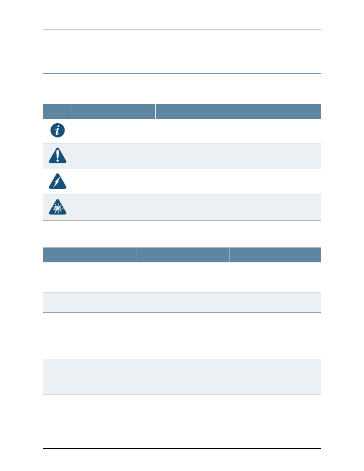
Table 1 on page xiv defines notice icons used in this guide.
Table 1: Notice Icons
DescriptionMeaningIcon
Indicates important features or instructions.Informational note
Indicates a situation that might result in loss of data or hardware damage.Caution
Alerts you to the risk of personal injury or death.Warning
Table 2 defines the text and syntax conventions used in this guide.
Table 2: Text and Syntax Conventions
Represents text that you type.Bold text like this
Fixed-width text like this
Italic text like this
Italic text like this
Represents output that appears on the
terminal screen.
•
Introduces important new terms.
•
Identifies book names.
•
Identifies RFC and Internet draft titles.
Represents variables (options for which
you substitute a value) in commands or
configuration statements.
Alerts you to the risk of personal injury from a laser.Laser warning
ExamplesDescriptionConvention
To enter configuration mode, type the
configure command:
user@host> configure
user@host> show chassis alarms
No alarms currently active
•
A policy term is a named structure
that defines match conditions and
actions.
•
Junos System Basics Configuration
Guide
•
RFC 1997, BGPCommunities Attribute
Configure the machine’s domain name:
[edit]
root@# set system domain-name
domain-name
Copyright © 2010, Juniper Networks, Inc.xiv
Page 15

Table 2: Text and Syntax Conventions (continued)
Plain text like this
Represents names of configuration
statements, commands, files, and
directories; IP addresses; configuration
hierarchy levels; or labels on routing
platform components.
About the Documentation
ExamplesDescriptionConvention
•
To configure a stub area, include the
stub statement at the [edit protocols
ospf area area-id] hierarchy level.
•
The console portis labeled CONSOLE.
stub <default-metric metric>;Enclose optional keywords or variables.< > (angle brackets)
| (pipe symbol)
# (pound sign)
[ ] (square brackets)
Indention and braces ( { } )
; (semicolon)
J-Web GUI Conventions
Bold text like this
Indicates a choice betweenthe mutually
exclusivekeywords or variables on either
side of the symbol. The set of choices is
often enclosed in parentheses for clarity.
same lineas theconfiguration statement
to which it applies.
Enclose a variable for which you can
substitute one or more values.
Identify a level in the configuration
hierarchy.
Identifies a leaf statement at a
configuration hierarchy level.
Represents J-Web graphical user
interface (GUI) items you click or select.
broadcast | multicast
(string1 | string2 | string3)
rsvp { # Required for dynamic MPLS onlyIndicates a comment specified on the
community name members [
community-ids ]
[edit]
routing-options {
static {
route default {
nexthop address;
retain;
}
}
}
•
In the Logical Interfaces box, select
All Interfaces.
•
To cancel the configuration, click
Cancel.
> (bold right angle bracket)
Documentation Feedback
We encourage you to provide feedback, comments, and suggestions so that we can
improve the documentation. You can send your comments to
techpubs-comments@juniper.net, or fill out the documentation feedback form at
https://www.juniper.net/cgi-bin/docbugreport/. If you are using e-mail, be sure to include
the following information with your comments:
•
Document or topic name
•
URL or page number
Separates levels in a hierarchy of J-Web
selections.
In the configuration editor hierarchy,
select Protocols>Ospf.
xvCopyright © 2010, Juniper Networks, Inc.
Page 16

Junos OS LN1000 Mobile Secure Router User Guide
•
Software release version (if applicable)
Requesting Technical Support
Technical product support is available throughthe JuniperNetworks Technical Assistance
Center (JTAC). If you are a customer with an active J-Care or JNASC support contract,
or are covered under warranty, and need post-sales technical support, you can access
our tools and resources online or open a case with JTAC.
•
JTAC policies—For a complete understanding of our JTAC procedures and policies,
review the JTAC User Guide located at
http://www.juniper.net/us/en/local/pdf/resource-guides/7100059-en.pdf .
•
Product warranties—For product warranty information, visit
http://www.juniper.net/support/warranty/ .
•
JTAC hours of operation—The JTAC centers have resources available 24 hours a day,
7 days a week, 365 days a year.
Self-Help Online Tools and Resources
For quick and easy problem resolution, Juniper Networks has designed an online
self-service portal called the Customer Support Center (CSC) that provides you with the
following features:
•
Find CSC offerings: http://www.juniper.net/customers/support/
•
Search for known bugs: http://www2.juniper.net/kb/
•
Find product documentation: http://www.juniper.net/techpubs/
•
Find solutions and answer questions using our Knowledge Base: http://kb.juniper.net/
•
Download the latest versions of software and review release notes:
http://www.juniper.net/customers/csc/software/
•
Search technical bulletins for relevant hardware and software notifications:
https://www.juniper.net/alerts/
•
Join and participate in the Juniper Networks Community Forum:
http://www.juniper.net/company/communities/
•
Open a case online in the CSC Case Management tool: http://www.juniper.net/cm/
To verify serviceentitlement by productserial number, use our Serial NumberEntitlement
(SNE) Tool: https://tools.juniper.net/SerialNumberEntitlementSearch/
Opening a Case with JTAC
You can open a case with JTAC on the Web or by telephone.
•
Use the Case Management tool in the CSC at http://www.juniper.net/cm/ .
•
Call 1-888-314-JTAC (1-888-314-5822 toll-free in the USA, Canada, and Mexico).
Copyright © 2010, Juniper Networks, Inc.xvi
Page 17

About the Documentation
For international or direct-dial options in countries without toll-free numbers, see
http://www.juniper.net/support/requesting-support.html .
xviiCopyright © 2010, Juniper Networks, Inc.
Page 18

Junos OS LN1000 Mobile Secure Router User Guide
Copyright © 2010, Juniper Networks, Inc.xviii
Page 19

PART 1
LN1000 Mobile Secure Router
•
LN1000 Mobile Secure Router Overview on page 3
•
Installing the Software on page 15
•
Configuring Gigabit Ethernet Interfaces to Match Your Topology on page 21
•
Location-Based IP Address Pools on page 25
•
Configuring Point-to-Point Protocol over Ethernet on page 29
•
Configuring PPPoE-Based Radio-to-Router Protocols on page 35
•
Configuring the R2CP Radio-to-Router Protocol on page 45
•
Summary of Junos Statements for the LN1000 Router on page 51
•
Junos Statement Hierarchy for the LN1000 Router on page 69
1Copyright © 2010, Juniper Networks, Inc.
Page 20

Junos OS LN1000 Mobile Secure Router User Guide
Copyright © 2010, Juniper Networks, Inc.2
Page 21

CHAPTER 1
LN1000 Mobile Secure Router Overview
This chapter includes the following topics:
•
LN1000 Mobile Secure Router Overview on page 3
•
Interface and Routing Features on the LN1000 Mobile Secure Router on page 5
•
Security Features on the LN1000 Mobile Secure Router on page 7
•
Administration Features on the LN1000 Mobile Secure Router on page 11
LN1000 Mobile Secure Router Overview
The LN1000 Mobile Secure Router is an embedded router that operates in both wire-line
and wireless environments with communication nodes that are either mobile or stationary.
The router provides reliable and secure data, voice, and video services. The LN1000-V
processes WAN and LAN routing functions. The router offers multiple DiffServ classes
and can interleave lower priority real-time data (voice traffic) with higher priority non
real-time data. It is developed on 3U compact node slot interface (VITA) architecture
as defined in the VITA 46.0 IEEE 1101.2 specifications and runs Junos OS for routing,
forwarding, and security.
The software supports the following features:
•
IPv4 and IPv6 unicast forwarding
•
Routing, including OSPF, BGP, RIPv2, IS-IS, and static routes
•
Multicast, including IGMPv2, IGMPv3, PIM, SDP, DVMRP, MLD, and source-specific
•
Encapsulation, including Ethernet (MAC and tagged), PPP, and PPPoE
•
PPPoE interface to radios and link quality metrics imported into OSPF
•
IP address management, including status, DHCP, and DHCP Relay
•
Tunneling, including GRE, IP in IP, and IPsec
•
NAT and stateful firewall filters, and intrusion detection
In addition, the following features are supported on the LN1000 router:
3Copyright © 2010, Juniper Networks, Inc.
Page 22

Junos OS LN1000 Mobile Secure Router User Guide
•
Support for non-volatile memory read-only (NVMRO). As a security feature unique to
the LN1000 Mobile Secure Router, NVMRO physically locks all non-volatile storage
against modifications. This includes the NAND system storage, the NOR boot flash,
and all Juniper Networks ID EEPROMS.
•
Support for advanced class-of-service (CoS)on Point-to-Point Protocol over Ethernet
(PPPoE) interfaces, whichincludes policingand shaping, weighted round robin (WRR)
queuing with prioritization, weighted random early detection (WRED), queuing based
on PPPoE interfaces, in addition to the supported VLAN/interface.
•
Support for up to eight ports of gigabit traffic with up to 1024 logical interfaces with
eight queues per logical interface and four priorities per queue. All eight ports interface
with the backplane. The LN1000 router supports most Layer 2 and Layer 3 protocols,
route redistribution, tunneling, multicast, routing, CoS, and security.
•
Support for location-based IP address pools for IPv4 addresses. A location pool can
specify IP addresses and subnet masks for multiple locations (relative positions of
cards within a shelf). You can configure an IP interface to obtain an IP address and
subnet mask from a selected location pool instead of specifying an explicit IP address
and subnet mask.
•
Support for PPPoE-based radio-to-router protocols. Extensions tothe PPPoEprotocol
include:
•
Messages that define how an external device provides the router with timely
information about the quality of a link connection
•
A flow control mechanism that indicates how much data the router can forward
The router uses the information provided in these PPPoE messages to dynamically
adjust theinterface speed of PPPlinks. When OSPF is notified of this change, it adjusts
the cost of the link and updates the routing tables accordingly.
•
Support for translation of Protocol Independent Multicast (PIM) join/prune messages
to Internet Group Management Protocol (IGMP) or Multicast Listener Discovery(MLD)
report/leave messages. To enable the use of IGMP or MLD to forward multicast traffic
across the PIM domains, you can configure the rendezvous point (RP) router that
resides between the edge domain and core domain to translate PIM join/prune
messages received from PIM neighbors on downstream interfaces into corresponding
IGMP or MLD report/leave messages. The router then transmits the report/leave
messages by proxying them to one or two upstream interfaces that you configure on
the RP router.
•
Support for Open Shortest Path First (OSPF) refresh and flooding reduction in stable
topologies, which facilitates OSPF scaling by reducing OSPF protocol traffic overhead
and maintains OSPF adjacencies and flood link-state advertisements (LSAs).
Junos OS on the LN1000 router supports many of the features that exist on the SRX
Series Services Gateways. For further information about these features, refer to the SRX
Series documentation located at:
http://www.juniper.net/techpubs/hardware/junos-srx/index.html
Related Topics LN1000–V Mobile Secure Router Hardware Guide•
Copyright © 2010, Juniper Networks, Inc.4
Page 23

Chapter 1: LN1000 Mobile Secure Router Overview
• Junos OS Interfaces and Routing Configuration Guide for J Series Services Routers and
SRX Series Services Gateways
• Junos OS Routing Protocols and Policies for Security Devicesfor JSeries Services Routers
and SRX Series Services Gateways
• Junos OS Class of Service Configuration Guide for Security Devices for J Series Services
Routers and SRX Series Services Gateways
• Junos OS Security Configuration Guide for J Series Services Routers and SRX Series
Services Gateways
• Junos OS Administration Guide for Security Devices for J Series Services Routers and
SRX Series Services Gateways
Interface and Routing Features on the LN1000 Mobile Secure Router
This section lists interface and routing features that are supported on the LN1000 router.
For further information on these features, see the SRX Series Services Gateway
documentation at http://www.juniper.net/techpubs/hardware/junos-srx/index.html.
Class of Service (CoS)
•
Code-point aliases
•
Classifiers
•
Forwarding classes
•
Transmission queues
•
Schedulers
•
Virtual channels
•
Tunnels
•
Policing
For more information, see the Junos OS Class of Service Configuration Guide for Security
Devices for J Series Services Routers and SRX Series Services Gateways.
Interfaces
•
Ethernet interface
•
Fast Ethernet interface
•
Generic routing encapsulation (GRE) interface
•
Gigabit Ethernet interface
•
Internally generated GRE interface
•
Internally generated link services interface
•
Internally generated IP-over-IP interface
5Copyright © 2010, Juniper Networks, Inc.
Page 24

Junos OS LN1000 Mobile Secure Router User Guide
•
Internally generated Protocol Independent Multicast (PIM) encapsulation interface
•
IP-over-IP encapsulation interface
•
Link services interface
•
Loopback interface
•
Passive monitoring interface
•
Point-to-Point Protocol interface
•
Point-to-Point Protocol over Ethernet (PPPoE) interface
For more information, see the Junos OS Interfaces and Routing Configuration Guide for J
Series Services Routers andSRX SeriesServices Gateways, Chapter 1, Interfaces Overview.
Multicast
•
Primary routing mode
•
Session Announcement Protocol (SAP)
•
Session Description Protocol (SDP)
•
Internet Group Management Protocol (IGMP)
•
Protocol Independent Multicast (PIM) Static RP
•
Filtering PIM Register Messages
•
PIM RPF Routing Table
For moreinformation, see Junos OS Interfaces and Routing Configuration Guide for J Series
Services Routers and SRX Series Services Gateways, Chapter 22, Multicast.
Routing Options
•
IPv4 options and broadcast Internet diagrams
•
Static routing
•
RIPv1, RIPv2
•
RIP next generation (RIPng)
•
OSPFv2
•
OSPFv3
•
IS-IS
•
BGP
•
Neighbor Discovery Protocol (NDP) and Secure Neighbor Discovery Protocol (SNDP)
•
Multiple virtual routers
•
Network Time Protocol (NTP)
•
Virtual Router Redundancy Protocol (VRRP)
Copyright © 2010, Juniper Networks, Inc.6
Page 25

For more information, see the Junos OS Interfaces and Routing Configuration Guide for J
Series Services Routers and SRX Series Services Gateways.
Stateless Firewall Filters
•
Stateless firewall filters
For more information, see Junos OS Routing Protocols and Policies Configuration Guide
for Security Devices for J Series Services Routers and SRX Series Services Gateways,
Chapter 9, Stateless Firewall Filters.
Security Features on the LN1000 Mobile Secure Router
This section lists security features that are supported on the LN1000 router. For
information about the interfaces that are supported on your device, see the Junos OS
Interfaces and Routing Configuration Guide. For further information on these features, see
the documentation for the SRX Series Services Gateway at
http://www.juniper.net/techpubs/hardware/junos-srx/index.html.
Application Layer Gateways (ALGs)
Chapter 1: LN1000 Mobile Secure Router Overview
•
FTP
•
Trivial File Transfer Protocol (TFTP)
•
Domain Name System (DNS)
•
Point-to-Point Tunneling Protocol (PPTP)
•
REAL
•
Remote procedure call (RPC)
•
Remote shell (RSH)
•
Real-Time Streaming Protocol (RTSP)
•
Structured Query Language (SQL)
•
TALK
For more information, see Junos OS Security Configuration Guide for J Series Services
Routers and SRX Series Services Gateways, Chapter 9, ALGs.
Attack Detection and Prevention
•
Bad IP option
•
Block fragment traffic
•
FIN flag without ACK flag set protection
•
ICMP flood protection
•
ICMP fragment protection
•
Large size ICMP packet protection
•
Loose source route option
7Copyright © 2010, Juniper Networks, Inc.
Page 26

Junos OS LN1000 Mobile Secure Router User Guide
•
IP record route option
•
IP security option
•
IP address spoof
•
IP stream option
•
IP strict source route option
•
IP address sweep
•
IP timestamp option
•
Land attack protection
•
Ping of death attack protection
•
Port scan
•
Source IP based session limit
•
SYN-ACK-ACK proxy protection
•
SYN and FIN flags set protection
•
SYN flood protection
•
SYN fragment protection
•
Teardrop attack protection
•
TCP packet without flag set protection
•
Unknown protocol protection
•
UDP flood protection
•
WinNuke attack protection
For more information, see Junos OS Security Configuration Guide for J Series Services
Routers and SRX Series Services Gateways, Chapter 35, Attack Detection and Prevention.
Firewall Authentication
•
Web authentication
•
Pass-through authentication
•
Local authentication server
•
RADIUS authentication server
•
LDAP authentication server
•
SecurID authentication server
For more information, see Junos OS Security Configuration Guide for J Series Services
Routers and SRX Series Services Gateways, Chapter 16, Firewall User Authentication.
Flow-based and Packet-based Processing
•
Flow-based processing
Copyright © 2010, Juniper Networks, Inc.8
Page 27

Chapter 1: LN1000 Mobile Secure Router Overview
•
Packet-based processing
•
Stateless packet-based services option
For more information, see Junos OS Security Configuration Guide for J Series Services
Routersand SRXSeries Services Gateways,Chapter 1, Introducing Junos OS for SRX Series
Services Gateways and Chapter 3, Introducing Junos OS for J Series Services Routers.
Intrusion Detection and Prevention (IDP)
•
IDP Policy
•
Intrusion prevention system (IPS) rulebase
•
Differentiated Services code point (DSCP) marking
•
IDP signature database
•
Application identification
•
IDP logging
For more information, see Junos OS Security Configuration Guide for J Series Services
Routers and SRX Series Services Gateways, Chapter 22, IDP Policies. For information on
IDP monitoring and debugging, see the Junos OS CLI Reference for JSeries Services Routers
and SRX Series Services Gateways.
IPsec
•
Policy-based and route-based VPNs
•
Tunnel mode
•
Authentication Header (AH) protocol
•
Encapsulating Security Payload (ESP) protocol
•
IKE phase 1
•
IKE phase 2
•
Manual key management
•
Autokey management
•
Antireplay (packet replay attack prevention)
•
Dead peer detection (DPD)
For more information, see Junos OS Security Configuration Guide for J Series Services
Routers and SRX Series Services Gateways, Chapter 18, Internet Protocol Security.
Network Address Translation (NAT)
•
Destination IP address translation
•
Static NAT
•
Rule-based NAT
•
Source IP address translation
9Copyright © 2010, Juniper Networks, Inc.
Page 28

Junos OS LN1000 Mobile Secure Router User Guide
•
Configuring proxy Address Resolution Protocol (ARP)
•
Persistent NAT
•
Disable source NAT port randomization
For more information, see Junos OS Security Configuration Guide for J Series Services
Routers and SRX Series Services Gateways, Chapter 42, Network Address Translation.
Public Key Infrastructure (PKI)
•
Internet Key Exchange (IKE) support
•
Entrust, Microsoft, and Verisign certificate authorities (CAs)
•
Automatic generation of self-signed certificates
•
Distinguished Encoding Rules (DER), Privacy-Enhanced Mail (PEM), Public-Key
Cryptography Standard 7 (PKCS7), and X509 certificate encoding
•
Manual installation of DER-encoded and PEM-encoded CRLs
•
Online certificate revocation list (CRL) retrieval through LDAP and HTTP
•
CRL update at user-specified interval
For more information, see Junos OS Security Configuration Guide for J Series Services
Routers and SRX Series Services Gateways, Chapter 19, Public Key Cryptography for
Certificates.
Security Policy
•
Address books
•
Policy application sets
•
Schedulers
•
Policy applications
•
Internet Control Message Protocol (ICMP) predefined policy application
•
Internet-related predefined policy applications
•
Microsoft predefined policy applications
•
Dynamic routing protocols predefined policy applications
•
Streaming video predefined policy applications
•
Sun remote procedure protocol (RPC) predefined policy applications
•
Security and tunnel predefined policy applications
•
IP-related predefined policy applications
•
Instant messaging predefined policy applications
•
Management predefined policy applications
•
Mail predefined policy applications
Copyright © 2010, Juniper Networks, Inc.10
Page 29

Chapter 1: LN1000 Mobile Secure Router Overview
•
UNIX predefined policy applications
•
Miscellaneous predefined policy applications
•
Custom policy Applications
•
Policy application timeouts
For more information, see Junos OS Security Configuration Guide for J Series Services
Routers and SRX Series Services Gateways, Chapter 8, Security Policy Applications.
Zones
•
Security zone
•
Functional zone
For more information, see Junos OS Security Configuration Guide for J Series Services
Routers and SRX Series Services Gateways, Chapter 4, Security Zones and Interfaces.
Administration Features on the LN1000 Mobile Secure Router
This section lists the administration features that are supported on the LN1000 router.
For further information on these features, see the documentation for the SRX Series
Services Gateway at http://www.juniper.net/techpubs/hardware/junos-srx/index.html.
Administrator Authentication
•
RADIUS
•
TACACS+
•
Local authentication
For more information, see Junos OS Administration Guide for Security Devices for J Series
Services Routers and SRX Series Services Gateways, Chapter 3, Managing Administrator
Authentication.
Alarms
•
Chassis alarms
•
Interface alarms
•
System alarms
For more information, see Junos OS Administration Guide for Security Devices for J Series
Services Routers and SRX Series Services Gateways, Chapter 11, Configuring and Monitoring
Alarms.
DHCP
•
Dynamic Host Configuration Protocol (DHCP) server address pools
•
DHCP server static mapping
•
DHCP client
11Copyright © 2010, Juniper Networks, Inc.
Page 30

Junos OS LN1000 Mobile Secure Router User Guide
•
DHCP server
•
DHCP relay agent
For more information, see Junos OS Administration Guide for Security Devices for J Series
Services Routers and SRX Series Services Gateways, Chapter 6, Configuring the Device
for DHCP.
Diagnostic Tools
•
Ping host
•
Ping MPLS
•
Traceroute
•
CLI terminal
•
J-flow version 8
For more information, see Junos OS Administration Guide for Security Devices for J Series
Services Routers and SRX Series Services Gateways, Chapter 17, Using Diagnostic Tools.
File Management Options
•
Clean up unnecessary files
•
Delete individual files
•
Delete backup software image
•
Download system files
•
Encrypt/decrypt configuration files
•
Manage account files
For more information, see Junos OS Administration Guide for Security Devices for J Series
Services Routers and SRX Series Services Gateways, Chapter 16, Managing Files.
Network Operations and Troubleshooting Automation
•
Extensible Stylesheet Language Transformations (XSLT) commit scripts
•
Operation scripts
•
Event policies
For more information, see Junos OS Administration Guide for Security Devices for J Series
Services Routers and SRX Series Services Gateways, Chapter 8, Automating Network
Operations and Troubleshooting.
Secure Web Access
•
Certificate authorities (CAs)
•
Hypertext Transfer Protocol (HTTP)
Copyright © 2010, Juniper Networks, Inc.12
Page 31

Chapter 1: LN1000 Mobile Secure Router Overview
For more information, see Junos OS Administration Guide for Security Devices for J Series
Services Routers and SRX Series Services Gateways, Chapter 2, Configuring Secure Web
Access.
System Log Files
•
Configuring system log messages
•
Sending system log messages to a file
•
Sending system log messages to a user terminal
•
Archiving system logs
•
Disabling system logs
•
Viewing system log messages
•
Viewing data plane logs
•
Session Logging with NAT
For more information, see Junos OS Administration Guide for Security Devices for J Series
Services Routers and SRX Series Services Gateways, Chapter 10, Monitoring Events and
Managing System Log Files.
Upgrade and Reboot Options
•
Software upgrades and downgrades
•
Boot device configuration
•
Boot device recovery
•
Chassis components control
•
Chassis restart
For more information, see Junos OS Administration Guide for Security Devices for J Series
Services Routers and SRX Series Services Gateways, Chapter 12, Performing Software
Upgrades and Reboots for the SRX Series Services Gateways.
User Interfaces
•
J-Web user interface
•
Command-line interface (CLI)
•
Network and Security Manager (NSM)
•
Junos Scope application
•
Junos XML protocol
For more information, see Junos OS Administration Guide for Security Devices for J Series
Services Routers and SRX Series Services Gateways, Chapter 1, User Interface Overview.
Also, see the Network and Security Manager: Configuring J Series Services Routers and SRX
Series Services Gateway Guide, and the Junos OS Junos Scope Software User Guide.
13Copyright © 2010, Juniper Networks, Inc.
Page 32

Junos OS LN1000 Mobile Secure Router User Guide
Copyright © 2010, Juniper Networks, Inc.14
Page 33

CHAPTER 2
Installing the Software
This chapter includes the following topics:
•
Installing Software on an LN1000 Mobile Secure Router on page 15
•
Setting Non-Volatile Memory Read-Only on page 15
•
Installing Software Upgrades from the Network on page 16
•
Configuring the Software on page 17
Installing Software on an LN1000 Mobile Secure Router
The LN1000 router is shipped with the Junos OS preinstalled on the internal NAND flash
drive and ready to configure when you poweron the device. Abackup copy of the software
is on a USB storage device. You configure the LN1000 router by issuing Junos OS
command-line interface (CLI) commands, either on a console device attached to the
CONSOLE port on the RoutingEngine, or overa telnet connection toa network connected
to the Ethernet port on the Routing Engine.
Gather the following information before you configure the device:
•
Hostname you want to the device to use on the network
•
Domain name you want the device to use
•
IP address and prefix length information for the Ethernet interface
•
IP address of a default router
•
IP address of a DNS server
•
Password for the root user
Related Topics Junos OS Administration Guide for Security Devices for J Series Services Routers and
•
SRX Series Services Gateways
Setting Non-Volatile Memory Read-Only
Before you upgrade the software or firmware on the LN1000 Mobile Secure Router, the
non-volatile memory read-only (NVMRO) switch must be clear to enable writing to
system storage. NVMRO must also be clear to permanently save any CLI changes.
15Copyright © 2010, Juniper Networks, Inc.
Page 34

Junos OS LN1000 Mobile Secure Router User Guide
To check the current setting of NVMRO:
1. Log in to the router as root.
2. From the shell, type:
root@host# sysctl kern.nvmro
kern.nvmro: 1
The value must be 0 to upgrade any files on the router. If the value is 0, proceed to
“Installing Software Upgrades from the Network” on page 16. If the value is 1, all
storage on the router is locked. You must reset the NVMRO switch located on the
rear transition module (RTM) to allow installation. See the LN1000–V Mobile Secure
Router Hardware Guide for the location of this switch.
3. Power off the system:
root@host# cli request system power-off
When you see the following message, the system is safely powered off:
syncing disks... All buffers synced.
Uptime: 20h14m55s
Turning system power off
Follow the instructions in the LN1000–V Mobile Secure Router Hardware Guide to
access the RTM and toggle the NVMRO switch.
•
To clear NVMRO (allow writing/updating), turn the switch on.
•
To set NVMRO (lock all storage), turn the switch off.
4. Reinstall the RTM and boot the router.
Related Topics LN1000–V Mobile Secure Router Hardware Guide•
Installing Software Upgrades from the Network
To install software upgrades by downloading files to the router:
1. Clean up the system:
root@host>request system storage cleanup
You are prompted to confirm deletion of a list of files:
2. Install the new package on the router, entering the following command:
root@host>request system software add unlink no-copy source
Replace source with /pathname/package/package-name (for example,
/var/tmp/junos-in-9.6R2.1.tar.gz).
The unlink option removes the package at the earliest opportunity so that the router
has enough capacity to complete the installation.
The no-copy option specifies that a software package is installed, but a copy of the
package is not saved.
Copyright © 2010, Juniper Networks, Inc.16
Page 35

The system automatically reboots.
CAUTION: During the upgrade process, the keyboard is locked to prevent interruption
of the firmware upgrade process. If the system loses power during the upgrade, the
upgrade will fail and the router may become unresponsive. Contact Juniper Networks
for assistance.
3. When the router reboots, log in to the router and verify the correct operation of the
new software image. You must do this before you can change NVMRO back to the
locked (read-only) mode.
NOTE: If the diagnostics fail three times, the IPMI powers down and therefore cannot
display the reasons for the failure. When the temperature thresholds are reached, IPMI
sends notification to the shelf manager.
Configuring the Software
Chapter 2: Installing the Software
The installation procedure connects the device to the network but does not enable it to
forward traffic.
To configure the software:
NOTE: Make sure NVMRO is clear for the configuration changes to be savedpermanently.
If not, the changes are lost on reboot.
1. Verify that the device is powered on.
2. Log in as the root user.
3. Start the CLI.
root# cli
root@>
4. Enter configuration mode.
configure
[edit]
root@#
5. Set the root authentication password by entering a cleartext password, or an
encrypted password, or an SSH public key string (DSA or RSA).
[edit]
root@# set system root-authentication plain-text-password
New password password
Retype new password password
6. Configure an administrator account on the device.
[edit]
17Copyright © 2010, Juniper Networks, Inc.
Page 36

Junos OS LN1000 Mobile Secure Router User Guide
root@# set system login user admin class super-user authentication
plain-text-password
7. Configure the password for the administrator account.
[edit]
root@# set system root-authentication plain-text-password
8. Commit the configuration to activate it on the device.
[edit]
root@# commit
9. Log in as the administrator you configured in Step 6.
10. Configure the name of the device. If the name includes spaces, enclose the name in
double quotation marks (“ ”).
configure
[edit]
admin@# set system host-name hostname
11. Configure the IP address and prefix length for the device’s Ethernet interface. You
can optionally use the location-based IP address Pools configuration. For further
information, see Chapter 4, Location-Based IP Address Pools.
[edit]
admin@# set interfaces ge-0/0/0 unit 0 family inet address address/prefix-length
12. Configure the traffic interfaces (ge-0/0/1–ge-0/0/7).
[edit]
admin@# set interfaces ge-0/0/1 unit 0 family inet address address/prefix-length
admin@# set interfaces ge-0/0/5 unit 0 family inet address address/prefix-length
13. Optionally, configure the default route.
[edit]
admin@# set routing-options static route 0.0.0.0/0 next-hop gateway
14. Configure basic security zones and bind them to traffic interfaces.
[edit]
admin@# set security zones security-zone trust interfaces ge-0/0/5
admin@# set security zones security-zone untrust interfaces ge-0/0/0
15. Configure basic security policies.
[edit]
admin@# set security policies from-zone trust to-zone untrust policy policy-name
match source-address any destination-address any application any
root@# set security policies from-zone trust to-zone untrust policy policy-name then
permit
16. Check the configuration for validity.
[edit]
admin@# commit check
configuration check succeeds
17. Commit the configuration to activate it on the device.
[edit]
Copyright © 2010, Juniper Networks, Inc.18
Page 37

Chapter 2: Installing the Software
admin@# commit
commit complete
18. Optionally, display the configuration to verify that it is correct.
admin@# show
19. When you have finished configuring the device, exit configuration mode.
[edit]
admin@host# exit
admin@host>
19Copyright © 2010, Juniper Networks, Inc.
Page 38

Junos OS LN1000 Mobile Secure Router User Guide
Copyright © 2010, Juniper Networks, Inc.20
Page 39

CHAPTER 3
Configuring Gigabit Ethernet Interfaces to
Match Your Topology
This chapter includes the following topics:
•
Configuring a Gigabit Ethernet Interface on page 21
•
Swapping Small Form-Factor Pluggable (SFP) Devices on page 22
Configuring a Gigabit Ethernet Interface
The LN1000 has eight Gigabit Ethernet interfaces that can terminate into a copper or
fiber Ethernet PHY device SFP (small form-factor pluggable). Depending on the type of
device into which you are terminating theseGigabit Ethernetinterfaces,you canconfigure
them to operate in SGMII or 1000Base-X mode. When configured in SGMII mode, you
can run ports speeds of 10/100/1000 Mbs in full or half duplex modes. When configured
in 1000Base-X mode, you can run these ports in 1000 Mbs mode. Use the mac-mode
statement in Chapter 8 to configure these options.
The LN1000-V rear transition module (RTM) supports both copper and fiber SFPs.
•
If you are running an LN1000 with the LN1000-V RTM and are using copper SFPs,
configure the mac-mode to SGMII.
•
If you arerunning an LN1000 with theLN1000-V RTMand areusing fiberSFPs, configure
the mac-mode to 1000Base-X.
Junos OS uses the following defaults:
•
mac-mode set to 1000Base-X
•
auto-negotiation set to ON
To add or change mac-mode fields:
set interfaces ge-0/0/1 gigether-options mac-mode sgmii|1000base-x
If you want to delete mac-mode, use the following command:
delete interfaces ge-0/0/1 gigether-options mac-mode
21Copyright © 2010, Juniper Networks, Inc.
Page 40

Junos OS LN1000 Mobile Secure Router User Guide
If you want to run in a different configuration to match your topology, you can use the
existing Junos auto-negotiation and link-speed statements and the new mac-mode
statement.
To enable or disable autonegotiation, use the following commands:
•
Enabling autonegotiation:
set interface ge-x/x/x gigether-options autoneg
•
Disabling autonegotiation:
set interface ge-x/x/x gigether-options no-autoneg
The delete interface ge-x/x/x gigether-options autoneg command does not disable
autonegotiation. The delete command is not applicable for this option.
To change the mac-mode fields:
delete interfaces ge-0/0/1 gigether-options mac-mode
Both the speed and link-mode attributes must be modified together in the same
configuration commit in order for either change to take effect.
Related Topics For further information, see the Junos OS Network Interfaces Configuration Guide.•
Swapping Small Form-Factor Pluggable (SFP) Devices
To swap SFPs, perform the following tasks:
1. Log in as the root user.
2. Start the CLI.
root# cli
root@>
3. Enter configuration mode.
configure
[edit]
root@#
4. Administratively disable the interface:
[edit]
root@# set interface name disable
5. Commit the configuration.
[edit]
root@# commit
6. Physically remove and reinsert the SFP.
7. Set the configuration of the interface:
[edit]
root@# set interface name gigether-options no-auto-negotiation
Copyright © 2010, Juniper Networks, Inc.22
Page 41

Chapter 3: Configuring Gigabit Ethernet Interfaces to Match Your Topology
8. Commit the configuration.
[edit]
root@# commit
9. Administratively enable the interface:
[edit]
root@# delete interface name disable
10. Commit the configuration.
[edit]
root@# commit
23Copyright © 2010, Juniper Networks, Inc.
Page 42

Junos OS LN1000 Mobile Secure Router User Guide
Copyright © 2010, Juniper Networks, Inc.24
Page 43

CHAPTER 4
Location-Based IP Address Pools
This chapter includes the following topics:
•
Location-Based IP Address Pools Overview on page 25
•
Configuring Location-Based IP Address Pools on page 26
•
Example: Configuring a Location-Based IP Address Pool on page 26
•
Verifying and Managing Location-Based IP Address Pools on page 27
Location-Based IP Address Pools Overview
The LN1000 router is a full-featuredJuniper Networksrouter running Junos OS with eight
gigabit Ethernet interfaces that exists on a single module. It operates in a network device
(such as a shelf) that contains multiple locations (slots). Each location supports eight
gigabit Ethernet interfaces. These locations can be populated with multiple cards. Each
card within this shelf is a separate entity (for example, a router or access device) in the
internal network of the shelf.
The management system for the shelf downloads a separate configuration to each card
when theyare initialized. To enablethis download, you must first configurean IP interface
on each card with an IP address and subnet mask that are predefined for each location
in the shelf.
You can use the Junos location-based IP address pools feature to configure the initial IP
interfaceof theLN1000 router. The configuration ispreserved when the shelf management
system downloads a separate configuration to this interface, unless it is explicitly
overwritten using existing CLI configuration commands (such as load override). If you
move an LN1000 router to a different slot within the shelf, initialization restarts, in which
case you might have to reconfigure the initial IP interface with the IP address and subnet
mask specified for the new location. The shelf management system can then download
a new configuration to the new interface.
A location poolcan specifyIP addresses and subnet masksfor multiple locations (relative
positions of cardswithin ashelf). You canconfigure an IP interfaceto obtainan IP address
and subnetmask from a selected location poolinstead of specifying anexplicit IPaddress
and subnet mask.
You can configure a maximum of 10 location-based IP address pools, each with a unique
name. Apool cancontain amaximum of32 IP addresses. Apool entry contains alocation
25Copyright © 2010, Juniper Networks, Inc.
Page 44

Junos OS LN1000 Mobile Secure Router User Guide
index that has a unique value within its pool and an IP address and subnet mask that do
not have to be unique. You can also define additional attributes for the pool entry as
required.
In the existing IP interface configuration, you can specify a location-based IP address
pool instead of an explicit IP address and subnet mask. You can configure an IP interface
using one of these IP address specifications types, but not both. An IPv4 address can be
configured for an IP interface as well as an IP pool.
Configuring Location-Based IP Address Pools
To configure IP address pools, perform the following tasks:
1. Configure a pool entry that contains a location index, an IP address, and subnet
mask.
2. Configure one IP address and subnet mask from the pool entry assigned to the IP
interface.
3. Configure up to 10 location-based address pools, each with a unique name.
4. Configure one IP address from each pool assigned to the IP interface.
Example: Configuring a Location-Based IP Address Pool
This configuration example creates two IPv4 and one IPv6 location-based IP address
pools, and selects one IPv4 and one IPv6 pool each for an IP interface.
[edit]
access {
address-assignment {
location-pool {
ipv4poolX {
family inet {
location {
1 address 10.0.0.1/24;
2 address 10.0.0.2/24;
3 address 172.0.0.3/24;
4 address 172.0.0.4/24;
5 address 192.0.0.5/24;
32 address 192.0.0.32/24;
}
}
}
ipv4poolY {
family inet {
location {
1 address 10.0.0.11/24;
3 address 172.0.0.33/24;
5 address 192.0.0.54/24;
}
}
}
Copyright © 2010, Juniper Networks, Inc.26
Page 45

Ipv6poolZ {
family inet6 {
location {
1 address fec0:1:1:1::1/64;
3 address fec0:1:1:1::3/64;
5 address fec0:1:1:1::5/64;
}
}
}
}
}
}
[edit]
interfaces ge-0/0/0 {
unit 0 {
family inet {
location-pool-address ipv4poolX;
}
family inet6 {
location-pool-address ipv6poolZ;
}
}
}
Chapter 4: Location-Based IP Address Pools
Using this configuration example, a router in slot 3 has an IPv4 address of 172.0.0.3/24
and an IPv6 address of fec0:1:1:1::3/64 assigned to gigabit Ethernet interface 0/0/0. If
you move the router to slot 5, it has an IPv4 address of 192.0.0.5/24 and an IPv6 address
of fec0:1:1:1::5/64 assigned to gigabit Ethernet interface 0/0/0.
Verifying and Managing Location-Based IP Address Pools
Purpose Display location-based IP address pools.
Action user@host> show access address-assignment location-pool
Meaning If a pool name is not specified, all pool entries are displayed.
Pool Family Location IP address
ipv4poolX inet 1 10.0.0.1/24
ipv4poolX inet 2 10.0.0.2/24
ipv4poolX inet 3 172.0.0.3/24
ipv4poolX inet 4 172.0.0.4/24
ipv4poolX inet 5 192.0.0.5/24
ipv4poolX inet 32 192.0.0.32/24
ipv4poolY inet 1 10.0.0.11/24
ipv4poolY inet 3 172.0.0.33/24
ipv4poolY inet 5 192.0.0.55/24
ipv6poolZ inet6 1 fec0:1:1:1::1/64
ipv6poolZ inet6 3 fec0:1:1:1::3/64
ipv6poolZ inet6 5 fec0:1:1:1::5/64
Related Topics • For more information, see the Junos OS SystemBasics and Services Command Reference
27Copyright © 2010, Juniper Networks, Inc.
Page 46

Junos OS LN1000 Mobile Secure Router User Guide
Copyright © 2010, Juniper Networks, Inc.28
Page 47

CHAPTER 5
Configuring Point-to-Point Protocol over
Ethernet
This chapter includes the following topics:
•
PPPoE Overview on page 29
•
Configuring PPPoE Interfaces on page 31
•
Verifying a PPPoE Configuration on page 33
PPPoE Overview
PPPoE establishes a point-to-point connection between the client and the server, also
called an access concentrator. Multiple hosts can be connected to the services router,
and their data can be authenticated, encrypted, and compressed before the traffic is
sent to the PPPoE session on the services router. PPPoE is easy to configure and enables
services to be managed on a per-user basis rather than on a per-site basis.
PPPoE Stages
The PPPoE interface to the access concentrator can be a Fast Ethernet interface or a
Gigabit Ethernet interface. If the interface is either Fast Ethernet or Gigabit Ethernet, use
a PPPoE encapsulation.
PPPoE has two stages, the discovery stage and the PPPoE session stage. In the discovery
stage, the client discovers the access concentrator by identifying the Ethernet media
access control (MAC) address of the access concentrator and establishing a PPPoE
session ID. In the PPPoE session stage, the client and the access concentrator build a
point-to-point connection over Ethernet, based on the information collected in the
discovery stage. The LN1000 router acts as an access concentrator.
PPPoE Discovery Stage
A router initiates the PPPoE discovery stage by broadcasting a PPPoE active discovery
initiation (PADI) packet. To provide a point-to-point connection over Ethernet, each
PPPoE session must learn the Ethernet MAC address of the access concentrator and
establish a session with a unique session ID. Because the network might have more than
one access concentrator, the discovery stage enables the client to communicate with
all of them and select one.
The PPPoE discovery stage consists of the following steps:
29Copyright © 2010, Juniper Networks, Inc.
Page 48

Junos OS LN1000 Mobile Secure Router User Guide
1. PPPoE active discovery initiation (PADI)—The client initiates a session by
broadcasting a PADI packet on the LAN to request a service.
2. PPPoE active discovery offer (PADO)—Any access concentrator that can provide
the service requested by the client in the PADI packet replies with a PADO packet
that contains it own name, the unicastaddress ofthe client, and the service requested.
An access concentrator can also use the PADO packet to offer other services to the
client.
3. PPPoE active discovery request (PADR)—From the PADOs it receives, the client
selects one accessconcentrator basedon its name or theservices offered andsends
it a PADR packet to indicate the service or services needed.
4. PPPoE active discovery Session-confirmation (PADS)—When the selected access
concentrator receives the PADR packet, it accepts or rejects the PPPoE session.
•
To accept the session, the access concentrator sends the client a PADS packet
with a unique session ID for a PPPoE session and a service name that identifies
the service under which it accepts the session.
•
To reject the session, the access concentrator sends the client a PADS packet
with a service name error and resets the session ID to zero.
PPPoE Session Stage
The PPPoE session stage starts after the PPPoE discovery stage has completed. The
access concentrator can start the PPPoE session after it sends the PADS packet to the
client, or the client can start the PPPoE session after it receives a PADS packet from the
access concentrator. The router supports multiple PPPoE sessions on each interface.
Each PPPoE session is uniquely identified by the Ethernet address of the peer and the
session ID. After the PPPoE session is established, data is sent as in any other PPP
encapsulation. The PPPoE information is encapsulated within an Ethernet frame and is
sent to a unicast address. In this stage, both the client and the server must allocate
resources for the PPPoE logical interface.
After a session is established, the client or the access concentrator can send a PPPoE
active discovery termination (PADT) packet anytime to terminate the session. The PADT
packet contains the destination address of the peer and the session ID of the session to
be terminated. After this packet is sent, the session is closed to PPPoE traffic.
Optional CHAP Authentication
For interfaces with PPPoE encapsulation, you can configure interfaces to support the
PPP Challenge Handshake Authentication Protocol (CHAP). When you enable CHAP on
an interface, the interface can authenticate its peer and be authenticated by its peer.
If you configure an interface to handle incoming CHAP packets only (by including the
passive statement at the [edit interfaces interface-name ppp-options chap] hierarchy
level), the interface does not challenge its peer. However, if the interface is challenged,
it responds to the challenge. If you do not include the passive statement, the interface
always challenges its peer.
Copyright © 2010, Juniper Networks, Inc.30
Page 49

Configuring the PPPoE Interfaces MTU
You can configure the maximum transmission unit (MTU) of the interface by including
the mtu statement at the [edit interfaces pp0] hierarchy level:
[edit interfaces pp0]
mtu bytes;
Disabling the Sending of PPPoE Keepalive Messages
When configuring the client, you can disable the sending of keepalive messages on a
logical interface by including the no-keepalives statement:
no-keepalives;
Configuring PPPoE Interfaces
To configure PPPoE, perform the following tasks:
1. Configure PPPoE encapsulation for an Ethernet interface.
Chapter 5: Configuring Point-to-Point Protocol over Ethernet
2. Specify the logical Ethernet interface as the underlying interface for the PPPoE
session.
3. Configure the operational mode as server.
4. Identify the access concentrator by a unique name.
5. Optionally, specify how many seconds to wait before attempting to reconnect.
6. Provide a name for the type of service provided by the access concentrator.
7. Optionally, configure the maximum transmission unit (MTU) of the interface.
8. Optionally, configure the PPPoE interface address.
9. Optionally, configure the MTU size for the protocol family.
10. Optionally, disable the sending of keepalive messages on the logical interface.
Setting the Appropriate Encapsulation on the PPPoE Interface
For PPPoE on an Ethernet interface, you must configure encapsulation on the logical
interface and use PPP over Ethernet encapsulation.
To configure logical interface encapsulation properties, include the encapsulation
statement:
encapsulation ppp-over-ether;
Configuring a PPPoE Underlying Interface
To configure the underlying Fast Ethernet, Gigabit Ethernet, and 10-Gigabit Ethernet
interfaces, include the underlying-interface statement at the [edit interfaces pp0 unit
logical-unit-number pppoe-options] hierarchy level:
[edit interfaces pp0]
unit logical-unit-number {
31Copyright © 2010, Juniper Networks, Inc.
Page 50

Junos OS LN1000 Mobile Secure Router User Guide
pppoe-options {
underlying-interface interface-name;
}
}
Specify the logical Ethernet interface as the underlying interface.
Identifying the Access Concentrator
When configuring a PPPoE client, identify the access concentrator by a unique name by
including the access-concentrator statement at the [edit interfaces interface-name unit
logical-unit-number pppoe-options] hierarchy level:
[edit interfaces pp0]
unit logical-unit-number{
pppoe-options {
access-concentrator name;
}
}
Specify the access concentrator name.
Configuring the PPPoE Service Name
When configuring a PPPoE client, identify the type of service provided by the access
concentrator—such as the name of the Internet service provider (ISP), class, or class of
service—by including the service-name statement at the [edit interfaces interface-name
unit logical-unit-number pppoe-options] hierarchy level:
[edit interfaces pp0]
unit logical-unit-number {
pppoe-options {
service-name name;
}
}
Configuring the PPPoE Server Mode
When configuring a PPPoE server, identify the mode by including the server statement
at the [edit interfaces interface-name unit logical-unit-number pppoe-options] hierarchy
level:
[edit interfaces pp0]
unit logical-unit-number {
pppoe-options {
server;
}
}
Configuring the PPPoE Source and Destination Addresses
When configuring a PPPoE client or server, assign source and destination addresses—for
example, 192.168.1.1/32 and 192.168.1.2. To assign the source and destination addresses,
include the address and destination statements at the [edit interfaces pp0 family inet]
hierarchy level:
[edit interfaces pp0 family inet]
Copyright © 2010, Juniper Networks, Inc.32
Page 51

Chapter 5: Configuring Point-to-Point Protocol over Ethernet
address address {
destination address;
}
Deriving the PPPoE Source Address from a Specified Interface
For a router supporting PPPoE, you can derive the source address from a specified
interface—for example, the loopback interface, lo0.0—and assign a destination
address—for example, 192.168.1.2. The specified interface must include a logical unit
number and have a configured IP address. To derive the source address and assign the
destination address, include the unnumbered-address and destination statements at the
[edit interfaces pp0 family inet] hierarchy level:
[edit interfaces pp0 family inet]
unnumbered-address interface-name destination address;
Configuring the PPPoE IP Address by Negotiation
You canhave the PPPoE client routerobtain anIP addressby negotiation with the remote
end. This method might require the access concentrator to use a RADIUS authentication
server. To obtain an IP address from the remote end by negotiation, include the
negotiate-address statement:
negotiate-address;
Configuring the Protocol MTU PPPoE
You can configure the maximum transmission unit (MTU) size for the protocol family.
Specify a range from 0 through 5012 bytes. Ensure that the size of the media MTU is
equal to or greater than the sum of the protocol MTU and the encapsulation overhead.
To set the MTU, include the mtu statement at the [edit interfaces pp0 family (inet | inet6
| mpls) ] hierarchy level:
[edit interfaces pp0 family (inet | inet6 | mpls) ]
mtu bytes;
Verifying a PPPoE Configuration
Purpose To verify a PPPoE configuration, you canissue the following operational modecommands:
Action • show interfaces f0/0/port extensive
• show interfaces pp0
• show pppoe interfaces
• show pppoe statistics
For more information about these operational mode commands, see the Junos OS
Interfaces Command Reference.
33Copyright © 2010, Juniper Networks, Inc.
Page 52

Junos OS LN1000 Mobile Secure Router User Guide
Copyright © 2010, Juniper Networks, Inc.34
Page 53

CHAPTER 6
Configuring PPPoE-Based
Radio-to-Router Protocols
This chapter includes the following topics:
•
PPPoE-Based Radio-to-Router Protocols Overview on page 35
•
Configuring PPPoE-Based Radio-to-Router Protocols on page 36
•
Example: Configuring the PPPoE-Based Radio-to-Router Protocol on page 37
•
Configuring a Gigabit Ethernet Interface on page 39
•
Verifying PPPoE Interfaces on page 40
•
Displaying Statistics for PPPoE on page 41
•
Credit Flow Control for PPPoE on page 41
•
Example: PPPoE Credit-Based Flow Control Configuration on page 42
•
Verifying Credit-Flow Control on page 42
•
Setting Tracing Options for PPPoE on page 43
PPPoE-Based Radio-to-Router Protocols Overview
Support for PPPoE-based radio-to-router protocols includes the following extensions
to the PPPoE protocol:
•
Messagesthat definehow anexternal device provides the router withtimely information
about the quality of a link connection
•
A flow control mechanism that indicates how much data the router can forward
The router usesthe information provided inthese PPPoE messages todynamicallyadjust
the interface speed. When OSPF is notified of this change, it adjusts the cost of the link
and updates the routing tables accordingly.
The radio provides ground-to-ground or ground-to-air communications with like devices.
When the radio picks up a signal from another device, it initiates a PPPoE session with a
directly connected router. The PPPoE session encapsulates the packets that are relayed
over a PPP link between the local and remote routers. The remote radio then forwards
traffic over an independent PPPoE session between the remote radio and the router to
35Copyright © 2010, Juniper Networks, Inc.
Page 54

Junos OS LN1000 Mobile Secure Router User Guide
which it is connected. The two routers exchange LCP and IPCP messages to configure
the link and exchange OSPF messages to establish the network topology.
The router and radio are deployed in highly dynamic environments, such as moving
vehicles. The quality of the radio link between the routers can vary significantly as a
vehicle moves behind an obstruction. Each radio monitors the link every 50 milliseconds
for changes in the link bandwidth, quality, and utilization. If any changes are detected,
the radios announce the new set of metrics to the respective routers through a PPPoE
Active Discovery Quality (PADQ) message, which is a nonstandard extension to the
PPPoE Discovery Protocol [RFC2516]. The router transforms these metrics into a
bandwidth value for the PPP link and compares it to the value currently in use. When the
router detects that the difference exceeds a user-specifiedthreshold, it adjusts the speed
of the PPP link. Anevent message notifiesOSPF of the change, which then triggers OSPF
to announce any resulting routing topology changes to its neighbors.
The PPPoE-based radio-to-router protocol notifies the router about neighbors joining or
leaving the network and to create and maintain OSPFadjacencies over the dynamic links
established between them. The costs assigned to these links are based on network
conditions and flow control information sentby the radios. Thecalculations and requests
to update interface speeds are performed by routines in a common library.
When PPPoE is used for applications, such as mobile radio, the radio links have variable
bandwidth. So a mobile radio can function in a PPPoE environment, PPPoE messaging
includes PADQ messages, which enable a link cost to be propagated to OSPF through
the evaluation of various link quality metrics. The router uses information from these
notifications along with user-configured parameters to calculate interface link costs that
are used by the routing protocols.
A radio can send an optional PADQ at any time to query or report link quality metrics.
When transmitting PPP streams over radio links, the quality of the link directly affects
the throughput. The PADQ packet is used by the radio modem to report link metrics.
To support the credit-basedflow control extensions described in RFC4938, PPPoE peers
can also grant each other forwarding credits. The grantee can forward traffic to the peer
only when it has a sufficient number of credits to do so. Credit-based forwarding allows
both sides of the session to agree to use a non-default credit scaling factor during the
PADR and PADS message exchange. Although this is used on both sides of the session,
this feature provides the radio client with a flow control mechanism that throttles traffic
by limiting the number of credits it grants to the router.
Related Topics For information onconfiguring aPPPoE server, see “ConfiguringPoint-to-PointProtocol
•
over Ethernet” in the Junos OS Network Interfaces Configuration Guide.
Configuring PPPoE-Based Radio-to-Router Protocols
To configure the PPPoE-based radio-to-router protocol:
1. Configure PPPoE encapsulation for an Ethernet interface.
2. Configure radio-router on the logical Ethernet interface.
Copyright © 2010, Juniper Networks, Inc.36
Page 55

Chapter 6: Configuring PPPoE-Based Radio-to-Router Protocols
3. Specify the logical Ethernet interface as the underlying interface for the PPPoE
session.
4. Configure the operational mode as server.
5. Optionally, identify the access concentrator by a unique name.
6. Optionally, specify how many seconds to wait before attempting to reconnect.
7. Optionally, provide aname forthe type of service provided by the access concentrator.
8. Optionally, configure the maximum transmission unit (MTU) of the interface.
9. Optionally, configure the MTU size for the protocol family.
10. Optionally, disable the sending of keepalive messages on the logical interface.
Related Topics For information onconfiguring aPPPoE server, see “ConfiguringPoint-to-PointProtocol
•
over Ethernet” in the Junos OS Network Interfaces Configuration Guide.
Example: Configuring the PPPoE-Based Radio-to-Router Protocol
This example shows how to configure the PPPoE-based radio-to-router protocol.
•
Requirements on page 37
•
Overview on page 37
•
Configuration on page 38
•
Verification on page 39
Requirements
Before you begin:
1. Configure network interfaces. See Example: Creating an Ethernet Interface.
2. Configure PPPoE interfaces. See Example: Configuring PPPoE Interfaces.
3. Configure PPPoE encapsulation on an Ethernet interface. See Example: Configuring
PPPoE Encapsulation on an Ethernet Interface.
4. Configure PPPoE encapsulation on an ATM-over-ADSL interface. See Example:
Configuring PPPoE Encapsulation on an ATM-over-ADSL Interface.
5. Configure CHAP authentication on a PPPoE interface. See Example: Configuring
CHAP Authentication on a PPPoE Interface.
Overview
In this example, you configure the ge-3/0/3 interface and set the bandwidth, resource,
latency, and quality to 100. You also set the threshold value to 10, and then configure
options on the logical interface.
37Copyright © 2010, Juniper Networks, Inc.
Page 56

Junos OS LN1000 Mobile Secure Router User Guide
Configuration
CLI Quick
Configuration
Step-by-Step
Procedure
To quickly configure the PPPoE-based radio-to-router protocol, copy the following
commands and paste them into the CLI:
[edit]
set interfaces ge-3/0/3 unit 1 radio-router bandwidth 100 resource 100 latency100 quality
100 threshold 10
set interfaces pp0 unit 1 pppoe-options underlying-interface ge-3/0/3 server
set interfaces pp0 unit 1 family inet unnumbered-address lo0.0 destination 192.168.1.2
set interfaces pp0 unit 1 family inet6 address lo0.0 destination fec0:1:1:1::2
The following example requires you to navigate various levels in the configuration
hierarchy. For instructions on how to do that, see Using the CLI Editor in Configuration
Mode.
To configure the PPPoE-based radio-to-router protocol:
1. Enable the PPPoE-based radio-to-router protocol.
[edit]
user@host# edit interfaces ge-3/0/3 unit 1 radio-router
2. Set the interface speed for the virtual link.
[edit interfaces ge-3/0/3 unit 1 radio-router]
user@host# set bandwidth 100 resource 100 latency 100 quality 100
3. Set the calculated and current interface speeds, as a percentage.
[edit interfaces ge-3/0/3 unit 1 radio-router]
user@host# set threshold 10
4. Configure options on the logical interface.
[edit interfaces pp0 unit 1]
user@host# set pppoe-options underlying-interface ge-3/0/3
user@host# set pppoe-options server
user@host# set family inet unnumbered-address lo0.0 destination 192.168.1.2
user@host# set family inet6 address lo0.0 destination fec0:1:1:1::2
Results From configuration mode, confirm your configuration by entering the show interfaces
command. If the output does not display the intended configuration, repeat the
configuration instructions in this example to correct it.
For brevity, this show interfaces command output includes only the configuration that is
relevant to this example. Any other configuration on the system has been replaced with
ellipses (...).
[edit]
user@host# show interfaces ge-3/0/3 {
unit 1
radio-router {
bandwidth 100;
resource 100;
Copyright © 2010, Juniper Networks, Inc.38
Page 57

Chapter 6: Configuring PPPoE-Based Radio-to-Router Protocols
latency 100;
quality 100;
threshold 10;
}
}
}
...
pp0 {
unit 1 {
pppoe-options {
underlying-interface ge-3/0/3;
server;
}
family inet {
unnumbered-address lo0.0 destination 192.168.1.2;
}
family inet6;
}
}
If you are done configuring the device, enter commit from configuration mode.
Verification
To confirm that the configuration is working properly, perform this task:
•
Verifying the PPPoE-based Radio-to-Router Protocol on page 39
Verifying the PPPoE-based Radio-to-Router Protocol
Purpose Verify the PPPoE-Based radio-to-router protocol.
Action From operational mode, enter the show interfaces command.
Related Topics Junos OS Feature Support Reference for SRX Series and J Series Devices•
• Understanding the PPPoE-Based Radio-to-Router Protocol
Configuring a Gigabit Ethernet Interface
The LN1000 has eight Gigabit Ethernet interfaces that can terminate into a copper or
fiber Ethernet PHY device SFP (small form-factor pluggable). Depending on the type of
device into which you are terminating theseGigabit Ethernetinterfaces,you canconfigure
them to operate in SGMII or 1000Base-X mode. When configured in SGMII mode, you
can run ports speeds of 10/100/1000 Mbs in full or half duplex modes. When configured
in 1000Base-X mode, you can run these ports in 1000 Mbs mode. Use the mac-mode
statement in Chapter 8 to configure these options.
The LN1000-V rear transition module (RTM) supports both copper and fiber SFPs.
•
If you are running an LN1000 with the LN1000-V RTM and are using copper SFPs,
configure the mac-mode to SGMII.
39Copyright © 2010, Juniper Networks, Inc.
Page 58

Junos OS LN1000 Mobile Secure Router User Guide
•
If you arerunning an LN1000 with theLN1000-V RTMand areusing fiberSFPs, configure
the mac-mode to 1000Base-X.
Junos OS uses the following defaults:
•
mac-mode set to 1000Base-X
•
auto-negotiation set to ON
To add or change mac-mode fields:
set interfaces ge-0/0/1 gigether-options mac-mode sgmii|1000base-x
If you want to delete mac-mode, use the following command:
delete interfaces ge-0/0/1 gigether-options mac-mode
If you want to run in a different configuration to match your topology, you can use the
existing Junos auto-negotiation and link-speed statements and the new mac-mode
statement.
To enable or disable autonegotiation, use the following commands:
•
Enabling autonegotiation:
set interface ge-x/x/x gigether-options autoneg
•
Disabling autonegotiation:
set interface ge-x/x/x gigether-options no-autoneg
The delete interface ge-x/x/x gigether-options autoneg command does not disable
autonegotiation. The delete command is not applicable for this option.
To change the mac-mode fields:
delete interfaces ge-0/0/1 gigether-options mac-mode
Both the speed and link-mode attributes must be modified together in the same
configuration commit in order for either change to take effect.
Related Topics For further information, see the Junos OS Network Interfaces Configuration Guide.•
Verifying PPPoE Interfaces
Purpose Display PPPoE interfaces information.
Action To display PPPoE interface information:•
user@host> show pppoe interfaces pp0.51 detail
pp0.51 Index 75
State: Session up, Session ID: 1,
Service name: None,
Configured AC name: None, Session AC name: None,
Remote MAC address: 00:11:22:33:44:55,
Session uptime: 00:04:18 ago,
Auto-reconnect timeout: Never, Idle timeout: Never,
Copyright © 2010, Juniper Networks, Inc.40
Page 59

Underlying interface: ge-0/0/1.0 Index 70
PADQ Current bandwidth: 750 Kbps, Maximum 1000 Kbps
Quality: 85, Resources 65, Latency 100 msec.
Dynamic bandwidth: 3 Kbps
• To display PPPoE terse interface information:
user@host> show pppoe interfaces terse pp0.51
Interface Admin Link Proto Local Remote
pp0.51 up up inet 5.1.1.1 --> 5.1.1.2
inet6 fe80::21f:12ff:fed2:2918/64
feee::5:1:1:1/126
Related Topics For more information,see theJunos OS System Basics and ServicesCommand Reference•
Displaying Statistics for PPPoE
Purpose Display PPPoE statistics.
Chapter 6: Configuring PPPoE-Based Radio-to-Router Protocols
Action user@host> show interfaces pp0.51 statistics
Sample Output Logical interface pp0.51 (Index 75) (SNMP ifIndex 137)
Flags: Point-To-Point SNMP-Traps 0x0 Encapsulation: PPPoE
PPPoE:
State: SessionUp, Session ID: 1,
Session AC name: None, Remote MAC address: 00:22:83:84:2f:03,
Underlying interface: ge-0/0/4.1 (Index 74)
Input packets : 20865
Output packets: 284636
Keepalive settings: Interval 10 seconds, Up-count 1, Down-count 3
Keepalive: Input: 0 (never), Output: 943 (00:00:06 ago)
LCP state: Opened
NCP state: inet: Opened, inet6: Opened, iso: Not-configured, mpls:
Not-configured
CHAP state: Closed
PAP state: Closed
Security: Zone: Null
Protocol inet, MTU: 1492
Flags: None
Addresses, Flags: Is-Preferred Is-Primary
Destination: 5.1.1.2, Local: 5.1.1.1
Protocol inet6, MTU: 1492
Flags: None
Addresses, Flags: Is-Preferred
Destination: fe80::/64, Local: fe80::21f:12ff:fed2:2918
Addresses, Flags: Is-Preferred Is-Primary
Destination: feee::5:1:1:0/126, Local: feee::5:1:1:1
Credit Flow Control for PPPoE
To support the credit-basedflow control extensions described in RFC4938, PPPoE peers
can grant each other forwarding credits. The grantee is allowed to forward traffic to the
peer only when it has a sufficient number of credits to do so. When credit-based
forwarding is used on both sides of the session, the radio client can throttle traffic by
limiting the number of credits it grants to the router.
41Copyright © 2010, Juniper Networks, Inc.
Page 60

Junos OS LN1000 Mobile Secure Router User Guide
The interfaces statement includes the radio-router attribute, which contains the
parameters used for rate-based scheduling and OSPF link cost calculations. It also
includes the credit attributeto indicate that credit-based packetscheduling is supported
on the PPPoE interfaces that reference this underlying interface. Interfaces that set the
encapsulation attribute support the PPPoE Active Discovery Grant (PADG) and PPPoE
ActiveDiscovery Credit (PADC) messagesin thesame way that the radio-router attribute
provides active support for the PPPoE Active Discovery Quality (PADQ) message.
The credit interval parameter controls how frequently the router generates credit
announcement messages. For PPPoE this corresponds to the interval between PADG
credit announcements for each session.
Example: PPPoE Credit-Based Flow Control Configuration
This example shows a PPPoE credit-based flow control configuration.
[edit interfaces ge-0/0/1]
unit 0 {
encapsulation ppp-over-ether;
radio-router {
credit {
interval 10;
}
bandwidth 80;
threshold 5;
}
}
Verifying Credit-Flow Control
Purpose Display PPPoE credit-flow control information about credits on each side of the PPPoE
session when credit processing is enabled on the interface.
Action user@host> show pppoe interface detail
pp0.51 Index 73
State: Session up, Session ID: 3,
Service name: None,
Configured AC name: None, Session AC name: None,
Remote MAC address: 00:22:83:84:2e:81,
Session uptime: 00:05:48 ago,
Auto-reconnect timeout: Never, Idle timeout: Never,
Underlying interface: ge-0/0/4.1 Index 72
PADG Credits: Local: 12345, Remote: 6789, Scale factor: 128 bytes
PADQ Current bandwidth: 750 Kbps, Maximum 1000 Kbps
Quality: 85, Resources 65, Latency 100 msec.
Dynamic bandwidth: 3 Kbps
pp0.1000 Index 71
State: Down, Session ID: 1,
Service name: None,
Configured AC name: None, Session AC name: None,
Remote MAC address: 00:00:00:00:00:00,
Auto-reconnect timeout: Never, Idle timeout: Never,
Underlying interface: ge-0/0/1.0 Index 70
PADG Credits: enabled
Dynamic bandwidth: enabled
Copyright © 2010, Juniper Networks, Inc.42
Page 61

Related Topics For more information,see theJunos OS System Basics and ServicesCommand Reference•
Setting Tracing Options for PPPoE
To trace theoperations of the router’s PPPoE process, includethe traceoptions statement
at the [edit protocols pppoe] hierarchy level:
[edit protocols pppoe]
traceoptions {
file filename <files number> <match regular-expression> <size size> <world-readable |
no-world-readable>;
flag flag;
level severity-level;
no-remote-trace;
}
To specify more than one tracing operation, include multiple flag statements.
You can specify the following flags in the traceoptions statement:
Chapter 6: Configuring PPPoE-Based Radio-to-Router Protocols
•
all—All areas of code
•
config—Configuration code
•
events—Event code
•
gres—Gres code
•
init—Initialization code
•
interface-db—Interface database code
•
memory—Memory management code
•
protocol—PPPoE protocol processing code
•
rtsock—Routing socket code
•
session-db—Session management code
•
signal—Signal handling code
•
state—State handling code
•
timer—Timer code
•
ui—User interface code
Related Topics • For general information about tracing, see the tracing and logging information in the
Junos System Basics Configuration Guide.
43Copyright © 2010, Juniper Networks, Inc.
Page 62

Junos OS LN1000 Mobile Secure Router User Guide
Copyright © 2010, Juniper Networks, Inc.44
Page 63

CHAPTER 7
Configuring the R2CP Radio-to-Router
Protocol
•
R2CP Radio-to-Router Protocol Overview on page 45
•
Configuring the R2CP Radio-to-Router Protocol on page 46
•
Verifying R2CP Interfaces on page 49
R2CP Radio-to-Router Protocol Overview
The Network Centric Waveform (NCW) radio-specific radio-to-router control protocol
(R2CP) issimilar to the PPPoE radio-to-router protocol. Both of theseprotocolsexchange
dynamic metric changes in the network that the routers use to update the OSPF
topologies.
In radio-router topologies, the router connects to the radio over a Gigabit Ethernet link
and the radio transmits packets over the radio frequency (RF) link. The radio periodically
sends metrics to the router, which uses RF link characteristics and other data to inform
the router on the shaping and OSPF link capacity. The router uses this information to
shape the data traffic and provide the OSPF link cost for its SPF calculations. The radio
functions like a Layer 2 switch and can only identify remote radio-router pairs using the
Layer 2 MAC addresses. With R2CP the router receives metrics for each neighboring
router, identified by the MAC address of the remote router. The R2CP daemon translates
the MAC addresses tolink the local IPv6address andsends the metrics foreach neighbor
to OSPF. Processing these metrics is similar to the handling of PPPoE PADQ metrics.
Unlike PPPoE, which is a point-to-point link, these R2CP neighbors are treated as nodes
in a broadcast LAN.
You must configure each neighbor node with a per unit scheduler for CoS. The scheduler
context defines the attributes of Junos class-of-service. To define CoS for each radio,
you can configure virtual channels to limit traffic. You need to configure virtual channels
for as many remote radio-router pairs as there are in the network. You configure virtual
channels on a logical interface. Each virtual channel can be configured to have a set of
eight queueswith a scheduler andan optional shaper. Whenthe radioinitiates the session
with a peer radio-router pair, a new session is created with the remote MAC address of
the router and the VLAN over which the traffic flows. Junos OS chooses from the list of
free virtual channels and assigns the remote MAC and the eight CoS queues and the
scheduler to this remote MAC address. All traffic destined to this remote MAC address
is subjected to the CoS that is defined in the virtual channel.
45Copyright © 2010, Juniper Networks, Inc.
Page 64

Junos OS LN1000 Mobile Secure Router User Guide
A virtual channel group is a collection of virtual channels. Each radio can have only one
virtual channel group assigned uniquely. If you have more than one radio connected to
the router, you must have one virtual channel group for each local radio-to-router pair.
Although avirtual channel group is assigned to a logical interface, a virtual channel is not
the same as a logical interface. The only features supported on a virtual channel are
queuing, packet scheduling, and accounting. Rewrite rules and routing protocols apply
to the entire logical interface.
All nodes in the R2CP network are in a broadcast LAN. The point-to-multipoint over LAN
protocol supports advertising different bandwidth information for neighbors on a
broadcast link. The network link is a point-to-multipoint link in the OSPFv3 link state
database, which uses existing OSPF neighbor discovery to provide automatic discovery
without configuration. It enables each node to advertise a different metric to every other
node in the network to accurately represent the cost of communication. The
p2mp-over-lan interface type under the OSPFv3 interface configuration enables you to
configure the interface. OSPFv3 then uses LAN procedures for neighbor discovery and
flooding, but represents the interface as point-to-multipoint in the link state database.
The interface type and router LSA are available under the following hierarchies:
[protocols ospf3 area area-id interface interface-name]
[routing-instances routing-instances-name protocols ospf3 area area-id interface
interface-name]
For example:
protocols {
ospf3 {
area 0.0.0.0 {
interface ge-0/0/2.0 {
interface-type p2mp-over-lan;
}
}
}
}
Related Topics Configuring the R2CP Radio-to-Router Protocol on page 46•
Configuring the R2CP Radio-to-Router Protocol
To configure the R2CP protocol:
1. Configure the interfaces.
The following example creates four logical interfaces on ge-0/0/2, using unit 52 for
R2CP control messages and units 101-193 for data traffic. The per-unit-scheduler
statement is required for R2CP.
interfaces {
ge-0/0/2 {
per-unit-scheduler;
vlan-tagging;
Copyright © 2010, Juniper Networks, Inc.46
Page 65

}
}
Chapter 7: Configuring the R2CP Radio-to-Router Protocol
unit 52 {
vlan-id 52;
family inet {
address 52.1.1.1/24;
}
}
unit 101 {
vlan-id 101;
family inet {
address 101.1.1.1/24;
}
}
unit 102 {
vlan-id 102;
family inet {
address 102.1.1.1/24;
}
}
unit 103 {
vlan-id 103;
family inet {
address 103.1.1.1/24;
}
}
2. Configure the R2CP protocol.
The following example configures g2-0/0/2.52 as the interface for R2CP control
messages, vg1 as the virtual-channel group, and ge-0/0/2.101-103 as data interfaces
using the radio-interface statement.
protocols {
r2cp {
radio myRadio {
interface ge-0/0/2.52;
virtual-channel-group vg1;
radio-interface ge-0/0/2.101;
radio-interface ge-0/0/2.102;
radio-interface ge-0/0/2.103;
}
}
}
3. Configure class of service.
The following example defines virtual-channels, their initial shaping-rates, and the
virtual-channel-group to which they belong. It also makes the association between
radio-interface interfaces and virtual-channel-group. In the class of service
configuration,the vc-shared-scheduler configuration statement isrequired for each
interface configured as a radio interface in the R2CP protocol configuration.
class-of-service {
virtual-channels {
vc1;
vc2;
47Copyright © 2010, Juniper Networks, Inc.
Page 66

Junos OS LN1000 Mobile Secure Router User Guide
vc3;
vc4;
}
virtual-channel-groups {
vg1 {
vc1 {
scheduler-map sm;
shaping-rate 15m;
default;
}
vc2 {
scheduler-map sm;
shaping-rate 20m;
}
vc3 {
scheduler-map sm;
shaping-rate 20m;
}
vc4 {
scheduler-map sm;
shaping-rate 20m;
}
}
}
forwarding-classes {
queue 0 DATA-queue;
}
interfaces {
ge-0/0/2 {
unit 101 {
virtual-channel-group vg1;
vc-shared-scheduler;
}
unit 102 {
virtual-channel-group vg1;
vc-shared-scheduler;
}
unit 103 {
virtual-channel-group vg1;
vc-shared-scheduler;
}
}
}
scheduler-maps {
sm {
forwarding-class DATA-queue scheduler sm-scheduler;
}
}
schedulers {
sm-scheduler {
transmit-rate percent 20;
buffer-size percent 20;
priority low;
}
}
}
Copyright © 2010, Juniper Networks, Inc.48
Page 67

Chapter 7: Configuring the R2CP Radio-to-Router Protocol
Related Topics For information on configuring network interfaces, see the Junos OS Network Interfaces
•
Configuration Guide.
Verifying R2CP Interfaces
Purpose Display R2CP interfaces information.
Action To display R2CP interface information:•
root@host> show r2cp interfaces
• To display R2CP information:
root@host> show r2cp radio extensive
Interface: ge-0/0/3.51
Nodes: 0
Node Packet Type Sent Received Errors
MIM - 1 0
ROM 1 - Heartbeats 0 0 0
Node Term 0 0 0
Node Term Ack 0 0 -
Heartbeat Timeouts 0
Node Term Timeouts 0
Session Packet Type Sent Received Errors
Init - 1 0
Init ACK 1 - Update - 0 0
Terminate 0 0 0
Terminate ACK 0 0 0
Terminate Timeouts 0
• To display R2CP session information:
root@host> show r2cp sessions extensive
Session: 1
Destination MAC address 01:02:03:04:05:06
Status: Established VLANs 201
Virtual channel: 2
Session Update: last received: 3.268 seconds
Current bandwidth: 22000 Kbps, Maximum 22000 Kbps
Quality: 100, Resources 100, Latency 100 msec.
Effective bandwidth: 952 Kbps, last change: 51.484 seconds
Updates below threshold: 1
Session Packet Type Sent Received Errors
Init - 1 0
Init ACK 1 - Update - 0 0
Terminate 0 0 0
49Copyright © 2010, Juniper Networks, Inc.
Page 68

Junos OS LN1000 Mobile Secure Router User Guide
Terminate ACK 0 0 0
Terminate Timeouts 0
Related Topics • For more information, see the Junos OS SystemBasics and Services Command Reference
Copyright © 2010, Juniper Networks, Inc.50
Page 69

CHAPTER 8
Summary of Junos Statements for the
LN1000 Router
address
Syntax address address;
Hierarchy Level [edit access address-assignment location-pool pool-name family inet location index]
Release Information Statement introduced in Junos OS Release 9.6.
Description Configure the IP address and subnet mask that corresponds to the slot location index
Options address—IP address and subnet mask.
Required Privilege
Level
Related Topics • Configuring Location-Based IP Address Pools on page 26
admin—To view this statement in the configuration.
admin-control—To add this statement to the configuration.
51Copyright © 2010, Juniper Networks, Inc.
Page 70

Junos OS LN1000 Mobile Secure Router User Guide
address-assignment
Syntax address-assignment {
location-pool {
pool-name {
family inet {
location {
index {
address address;
}
}
}
}
}
}
Hierarchy Level [edit access]
Release Information Statement introduced in Junos OS Release 9.6.
Description Configure the address of a location-based IP address pool.
Options The remaining statements are explained separately.
Required Privilege
Level
admin—To view this statement in the configuration.
admin-control—To add this statement to the configuration.
Related Topics • Configuring Location-Based IP Address Pools on page 26
apply-groups
Syntax apply-groups;
Hierarchy Level [edit interfaces interface-name unit logical-unit-number radio-router]
Release Information Statement introduced in Junos OS Release 9.6.
Description Apply the groups from which to inherit configuration data. If radio-router is set without
any other attributes specified, the first four values become 100 and threshold stays at
10, and capacity, margin, and delay are deprecated. If radio-router is set, do not change
the OSPF reference-bandwidth value because this generates an incorrect link cost.
Required Privilege
Level
interface—To view this statement in the configuration.
interface-control—To add this statement to the configuration.
Related Topics • Configuring PPPoE-Based Radio-to-Router Protocols on page 36
Copyright © 2010, Juniper Networks, Inc.52
Page 71

Chapter 8: Summary of Junos Statements for the LN1000 Router
bandwidth
Syntax bandwidth weight;
Hierarchy Level [edit interfaces interface-name unit logical-unit-number radio-router]
Release Information Statement introduced in Junos OS Release 9.6.
Description Configure the weight of the bandwidth factor when calculating an effective interface
bandwidth.
Options weight—Factor used to calculate interface bandwidth.
Range: 0 through 100
Default: 100
Required Privilege
Level
interface—To view this statement in the configuration.
interface-control—To add this statement to the configuration.
Related Topics • Configuring PPPoE-Based Radio-to-Router Protocols on page 36
• R2CP Radio-to-Router Protocol Overview on page 45
credit
Syntax credit {
interval seconds;
}
Hierarchy Level [edit interfaces interface-name unit logical-unit-number radio-router]
Release Information Statement introduced in Junos OS Release 10.1.
Description Configure the credit-based packet scheduling.
Options The remaining statements are explained separately.
Required Privilege
Level
interface—To view this statement in the configuration.
interface-control—To add this statement to the configuration.
Related Topics • Configuring PPPoE-Based Radio-to-Router Protocols on page 36
53Copyright © 2010, Juniper Networks, Inc.
Page 72

Junos OS LN1000 Mobile Secure Router User Guide
data-rate
Syntax data-rate weight;
Hierarchy Level [edit interfaces interface-name unit logical-unit-number radio-router]
Release Information Statement introduced in Junos OS Release 10.2.
Description Configure the weight of the resource factor when calculating an effective data rate.
Options weight—Factor used to calculate data rate.
Range: 0 through 100
Default: 100
Required Privilege
Level
Related Topics • R2CP Radio-to-Router Protocol Overview on page 45
interface—To view this statement in the configuration.
interface-control—To add this statement to the configuration.
disable
Syntax disable;
Hierarchy Level [edit protocol r2cp]
Release Information Statement introduced in Junos OS Release 10.2.
Description Disable R2CP on the system.
Required Privilege
Level
Related Topics • R2CP Radio-to-Router Protocol Overview on page 45
routing—To view this statement in the configuration.
routing-control—To add this statement to the configuration.
Copyright © 2010, Juniper Networks, Inc.54
Page 73

Chapter 8: Summary of Junos Statements for the LN1000 Router
family
Syntax family inet {
location {
index {
address address;
}
}
}
Hierarchy Level [edit access address-assignment location-pool pool-name]
Release Information Statement introduced in Junos OS Release 9.6.
Description Configure protocol family information for the logical interface.
Options family—Specifies the protocol family:
• inet—Specifies the Internet Protocol version 4 suite
The remaining statements are explained separately.
Required Privilege
Level
interface—To view this statement in the configuration.
interface-control—To add this statement to the configuration.
Related Topics • Configuring Location-Based IP Address Pools on page 26
hub-assist
Syntax hub-assist weight;
Hierarchy Level [edit interfaces interface-name unit logical-unit-number radio-router]
Release Information Statement introduced in Junos OS Release 10.2.
Description Configure the weight of the resource factor when calculating an effective interface
bandwidth.
Options weight—Factor used to calculate interface bandwidth.
Range: 0 through 100
Default: 100
Required Privilege
Level
interface—To view this statement in the configuration.
interface-control—To add this statement to the configuration.
Related Topics • Configuring PPPoE-Based Radio-to-Router Protocols on page 36
55Copyright © 2010, Juniper Networks, Inc.
Page 74

Junos OS LN1000 Mobile Secure Router User Guide
interface
Syntax interface interface-name unit unit
Hierarchy Level [edit protocol r2cp radio radio-name]
Release Information Statement introduced in Junos OS Release 10.2.
Description Configure the interface that receives R2CP messages.
Options interface-name—Name of the radio interface.
unit—Radio unit number.
Required Privilege
Level
Related Topics • R2CP Radio-to-Router Protocol Overview on page 45
routing—To view this statement in the configuration.
routing-control—To add this statement to the configuration.
interval
Syntax interval seconds;
Hierarchy Level [edit interfaces interface-name unit logical-unit-number radio-router credit]
Release Information Statement introduced in Junos OS Release 10.1.
Description Configure the frequency that the router generates credit announcement messages.
Options seconds—Interval between PADG credit announcements for each session.
Range: 0 through 60
Default: 1
Required Privilege
Level
Related Topics • Configuring PPPoE-Based Radio-to-Router Protocols on page 36
interface—To view this statement in the configuration.
interface-control—To add this statement to the configuration.
Copyright © 2010, Juniper Networks, Inc.56
Page 75

Chapter 8: Summary of Junos Statements for the LN1000 Router
latency
Syntax latency weight;
Hierarchy Level [edit interfaces interface-name unit logical-unit-number radio-router]
Release Information Statement introduced in Junos OS Release 9.6.
Description Configure the weight of the latency factor when calculating an effective interface
bandwidth.
Options weight—Factor used to calculate interface bandwidth.
Range: 0 through 100
Default: 100
Required Privilege
Level
interface—To view this statement in the configuration.
interface-control—To add this statement to the configuration.
Related Topics • Configuring PPPoE-Based Radio-to-Router Protocols on page 36
location
Syntax location {
index {
address address;
}
}
Hierarchy Level [edit access address-assignment location-pool pool-name family inet]
Release Information Statement introduced in Junos OS Release 9.6.
Description Configure the location for a router running Junos OS.
Options index—a location number.
The remaining statements are explained separately.
Required Privilege
Level
admin—To view this statement in the configuration.
admin-control—To add this statement to the configuration.
Related Topics • Configuring Location-Based IP Address Pools on page 26
57Copyright © 2010, Juniper Networks, Inc.
Page 76

Junos OS LN1000 Mobile Secure Router User Guide
location-pool
Syntax location-pool {
pool-name {
family inet {
location {
index {
address address;
}
}
}
}
}
Hierarchy Level [edit access address-assignment],
Release Information Statement introduced in Junos OS Release 9.6.
Description Configure the name of a location-based IP address pool.
Options pool-name—Name assigned to the location-based address pool.
The remaining statements are explained separately.
Required Privilege
Level
admin—To view this statement in the configuration.
admin-control—To add this statement to the configuration.
Related Topics • Configuring Location-Based IP Address Pools on page 26
location-pool-address
Syntax location-pool-address pool-name;
Hierarchy Level [edit interfaces interface-name unit logical-unit-number family inet]
Release Information Statement introduced in Junos OS Release 9.6.
Description Select the location-based IP address pool from the location ofthe IP address and subnet
mask for an IP interface.
Options pool-name—Name assigned to the location-based address pool.
Required Privilege
Level
interface—To view this statement in the configuration.
interface-control—To add this statement to the configuration.
Related Topics • Configuring Location-Based IP Address Pools on page 26
Copyright © 2010, Juniper Networks, Inc.58
Page 77

Chapter 8: Summary of Junos Statements for the LN1000 Router
mac-mode (Gigabit Ethernet)
Syntax mac-mode (sgmii | 1000base-x);
Hierarchy Level [edit interfaces interface-name mac-mode]
Release Information Statement introduced in Junos OS Release 10.0.
Description For Gigabit Ethernet interfaces only, specify whether the MAC address for the interface
is configured with the Serial GigabitMedia IndependentInterface(SGMII) or1000Base-X
physical layer protocol. Speeds of 10 Mbps and100 Mbps are valid only with a MAC mode
of SGMII. Autonegotiation for MAC mode must be enabled for 1000Base-X.
Default SGMII
Options sgmii—Specifies the serial Gigabit Media Independent Interface.
1000base-x—Specifies the physical layer protocol.
Usage Guidelines See Configuring a Gigabit Ethernet Interface.
Required Privilege
Level
interface—To view this statement in the configuration.
interface-control—To add this statement to the configuration.
node-terminate-count
Syntax node-terminate-count count;
Hierarchy Level [edit protocol r2cp]
Release Information Statement introduced in Junos OS Release 10.2.
Description Configure the number of node terminate retransmits attempted when a node terminate
ACK has not been received before radio/router adjacency is terminated.
Options count—Number of node terminate retransmits
Range: 1 through 5
Default: 3
Required Privilege
Level
Related Topics • R2CP Radio-to-Router Protocol Overview on page 45
routing—To view this statement in the configuration.
routing-control—To add this statement to the configuration.
59Copyright © 2010, Juniper Networks, Inc.
Page 78

Junos OS LN1000 Mobile Secure Router User Guide
node-terminate-interval
Syntax node-terminate-interval interval;
Hierarchy Level [edit protocol r2cp]
Release Information Statement introduced in Junos OS Release 10.2.
Description Configure the interval between node terminate retransmits.
Options interval—Interval in milliseconds.
Range: 100 through 5000
Default: 1000
Required Privilege
Level
Related Topics • R2CP Radio-to-Router Protocol Overview on page 45
routing—To view this statement in the configuration.
routing-control—To add this statement to the configuration.
quality
Syntax quality weight;
Hierarchy Level [edit interfaces interface-name unit logical-unit-number radio-router]
Release Information Statement introduced in Junos OS Release 9.6.
Description Configure the weight of the quality factor when calculating an effective interface
bandwidth.
Options weight—Factor used to calculate interface bandwidth.
Range: 0 through 100
Default: 100
Required Privilege
Level
interface—To view this statement in the configuration.
interface-control—To add this statement to the configuration.
Related Topics • Configuring PPPoE-Based Radio-to-Router Protocols on page 36
Copyright © 2010, Juniper Networks, Inc.60
Page 79

r2cp
Chapter 8: Summary of Junos Statements for the LN1000 Router
Syntax r2cp {
{enable | disable};
traceoptions {
flag flags;
file filename;
}
server-port port-number;
node-terminate-count count;
node-terminate-interval interval;
session-terminate-count count;
session-terminate-interval interval;
radio radio-name {
interface interface unit unit-number;
radio-interface interface unit number;
virtual-channel-group vc-group;
}
}
Hierarchy Level [edit protocols]
Release Information Statement introduced in Junos OS Release 10.2.
Description Configure the network interfaces that are used for protocol updates. By default, the
protocol is disabled on all interfaces.
Options The statements are explained separately.
Required Privilege
Level
routing—To view this statement in the configuration.
routing-control—To add this statement to the configuration.
Related Topics • R2CP Radio-to-Router Protocol Overview on page 45
61Copyright © 2010, Juniper Networks, Inc.
Page 80

Junos OS LN1000 Mobile Secure Router User Guide
radio
Syntax radio radio-name {
interface interface unit unit-number;
virtual-channel-group vc-group-name;
radio-interface interface unit number;
}
Hierarchy Level [edit protocol r2cp]
Release Information Statement introduced in Junos OS Release 10.2.
Description Configure the arbitrary name that describes the R2CP radio that exchanges messages
and listens for acknowledgements. The interfaces and radio interfaces must reference
the same Ethernet port for a particular radio. In addition, the logical interface configured
by the radio interface can only be referenced by a single radio.
Options radio-name—Name of the R2CP radio.
The remaining statements are explained separately.
Required Privilege
Level
routing—To view this statement in the configuration.
routing-control—To add this statement to the configuration.
Related Topics • R2CP Radio-to-Router Protocol Overview on page 45
radio-interface
Syntax radio-interface interface unit unit;
Hierarchy Level [edit protocol r2cp radio radio-name]
Release Information Statement introduced in Junos OS Release 10.2.
Description Configure the attributes that identify the VLANs managed through the R2CP protocol.
Options interface—Name of the interface.
unit—Unit number.
Required Privilege
Level
routing—To view this statement in the configuration.
routing-control—To add this statement to the configuration.
Related Topics • R2CP Radio-to-Router Protocol Overview on page 45
Copyright © 2010, Juniper Networks, Inc.62
Page 81

Chapter 8: Summary of Junos Statements for the LN1000 Router
radio-router
Syntax radio-router {
bandwidth weight;
latency weight;
quality weight;
resource weight;
threshold percentage;
credit {
interval seconds;
}
}
Hierarchy Level [edit interfaces interface-name unit logical-unit-number]
Release Information Statement introduced in Junos OS Release 10.1.
Description Configure the metric announcements that are received on the interface and processed
by the router to control the flow of traffic and manage the speed of the link, resulting in
a corresponding adjustment of OSPF cost.
Options The remaining statements are explained separately.
Required Privilege
Level
interface—To view this statement in the configuration.
interface-control—To add this statement to the configuration.
Related Topics • Configuring PPPoE-Based Radio-to-Router Protocols on page 36
resource
Syntax resource weight;
Hierarchy Level [edit interfaces interface-name unit logical-unit-number radio-router]
Release Information Statement introduced in Junos OS Release 9.6.
Description Configure the weight of the resource factor when calculating an effective interface
bandwidth.
Options weight—Factor used to calculate interface bandwidth.
Range: 0 through 100
Default: 100
Required Privilege
Level
interface—To view this statement in the configuration.
interface-control—To add this statement to the configuration.
Related Topics • Configuring PPPoE-Based Radio-to-Router Protocols on page 36
63Copyright © 2010, Juniper Networks, Inc.
Page 82

Junos OS LN1000 Mobile Secure Router User Guide
server-port
Syntax server-port port-number;
Hierarchy Level [edit protocol r2cp]
Release Information Statement introduced in Junos OS Release 10.2.
Description Configure the R2CP server that exchanges messages and listens for acknowledgements.
Options port-number—Number of the server port.
Default: UDP port 28762
Required Privilege
Level
Related Topics • R2CP Radio-to-Router Protocol Overview on page 45
routing—To view this statement in the configuration.
routing-control—To add this statement to the configuration.
session-terminate-count
Syntax session-terminate-count count;
Hierarchy Level [edit protocol r2cp radio]
Release Information Statement introduced in Junos OS Release 10.2.
Description Configure thenumber of Session Terminate retransmits to be attempted when aSession
Terminate ACK has not been received before the session terminated.
Options count—Number of session terminate retransmits
Range: 1 through 5
Default: 3
Required Privilege
Level
routing—To view this statement in the configuration.
routing-control—To add this statement to the configuration.
Related Topics • R2CP Radio-to-Router Protocol Overview on page 45
Copyright © 2010, Juniper Networks, Inc.64
Page 83

Chapter 8: Summary of Junos Statements for the LN1000 Router
session-terminate-interval
Syntax session-terminate-interval interval;
Hierarchy Level [edit protocol r2cp]
Release Information Statement introduced in Junos OS Release 10.2.
Description Configure the interval between Session Terminate retransmits.
Options interval—Interval in milliseconds
Range: 100 through 5000
Default: 1000
Required Privilege
Level
Related Topics • R2CP Radio-to-Router Protocol Overview on page 45
routing—To view this statement in the configuration.
routing-control—To add this statement to the configuration.
threshold
Syntax threshold percentage;
Hierarchy Level [edit interfaces interface-name unit logical-unit-number radio-router]
Release Information Statement introduced in Junos OS Release 9.6.
Description Configure the percentage by which the effective interface speed for the session must
change before the OSPF protocol is notified.
Options weight—Factor used to calculate interface bandwidth
Range: 0 through 100
Default: 100
Required Privilege
Level
interface—To view this statement in the configuration.
interface-control—To add this statement to the configuration.
Related Topics • Configuring PPPoE-Based Radio-to-Router Protocols on page 36
65Copyright © 2010, Juniper Networks, Inc.
Page 84

Junos OS LN1000 Mobile Secure Router User Guide
traceoptions
Syntax traceoptions {
file filename;
flag flag;
}
Hierarchy Level [edit protocol r2cp]
Release Information Statement introduced in Junos OS Release 10.2.
Description Configure the trace options for R2CP.
Options file filename—Name of the file to receive the output of the tracing operation.
flag flag—Tracing operation to perform. To specify more than one tracing operation,
include multiple flag statements. You can include the following flags:
• all—All tracing operations
• configuration—Configuration operations
• event—All tracing events
• interface—Interface operations
• node—Node events
• packet—Packet events
• rtsock —Routing socket operations
• session—Session events
• socket—Socket events
• timer—Timer events
• virtual-channel—Virtual channel events
Required Privilege
Level
routing—To view this statement in the configuration.
routing-control—To add this statement to the configuration.
Related Topics • R2CP Radio-to-Router Protocol Overview on page 45
Copyright © 2010, Juniper Networks, Inc.66
Page 85

Chapter 8: Summary of Junos Statements for the LN1000 Router
virtual-channel-group
Syntax virtual-channel-group vc-group;
Hierarchy Level [edit protocol r2cp radio radio-name]
Release Information Statement introduced in Junos OS Release 10.2.
Description Configure the virtual channel group that is used when allocating a virtual circuit for each
learned MAC address.
Options vc-group—Name of virtual channel group.
Required Privilege
Level
routing—To view this statement in the configuration.
routing-control—To add this statement to the configuration.
Related Topics • R2CP Radio-to-Router Protocol Overview on page 45
67Copyright © 2010, Juniper Networks, Inc.
Page 86

Junos OS LN1000 Mobile Secure Router User Guide
Copyright © 2010, Juniper Networks, Inc.68
Page 87

CHAPTER 9
Junos Statement Hierarchy for the
LN1000 Router
•
[edit access address-assignment location-pool] Hierarchy Level on page 69
•
[edit interfaces gigether-options] Hierarchy Level on page 69
•
[edit interfaces unit family inet location-pool-address] Hierarchy Level on page 70
•
[edit interfaces unit radio-router] Hierarchy Level on page 70
•
[edit protocols r2cp] Hierarchy Level on page 70
[edit access address-assignment location-pool] Hierarchy Level
access {
address-assignment {
location-pool {
pool-name {
family inet {
location {
index {
address address;
}
}
}
}
}
}
[edit interfaces gigether-options] Hierarchy Level
interfaces {
interface-name {
gigether-options {
auto-negotiation | no-auto-negotiation;
mac-mode (sgmii | 1000base-x);
}
speed (10m | 100m | 1g);
link-mode (full-duplex | half-duplex);
}
69Copyright © 2010, Juniper Networks, Inc.
Page 88

Junos OS LN1000 Mobile Secure Router User Guide
[edit interfaces unit family inet location-pool-address] Hierarchy Level
interfaces {
interface-name {
unit logical-unit-number {
family inet {
location-pool-address pool-name;
}
}
}
[edit interfaces unit radio-router] Hierarchy Level
interfaces {
interface-name {
unit logical-unit-number {
radio-router {
bandwidth weight;
data-rate weight;
latency weight;
quality weight;
resource weight;
threshold percentage;
}
}
}
[edit protocols r2cp] Hierarchy Level
protocols {
r2cp {
(enable | disable);
traceoptions {
flag flags;
file filename;
}
server-port port-number;
node-terminate-count count;
node-terminate-interval interval;
session-terminate-count count;
session-terminate-interval interval;
radio radio-name {
interface interface unit unit-number;
virtual-channel-group vc-group-name;
radio-interface interface unit unit-number;
}
}
Copyright © 2010, Juniper Networks, Inc.70
Page 89

PART 2
Index
•
Index on page 73
71Copyright © 2010, Juniper Networks, Inc.
Page 90

Junos OS LN1000 Mobile Secure Router User Guide
Copyright © 2010, Juniper Networks, Inc.72
Page 91

Index
Symbols
#, comments in configuration statements....................xv
( ), in syntax descriptions.....................................................xv
< >, in syntax descriptions....................................................xv
[ ], in configuration statements.........................................xv
{ }, in configuration statements.........................................xv
| (pipe), in syntax descriptions...........................................xv
A
access concentrator...............................................................32
address statement..................................................................51
address-assignment statement.......................................52
administration features supported ...................................11
alarms............................................................................................11
application layer gateways (ALGs) ....................................7
apply-groups statement......................................................52
attack detection and prevention..........................................7
device name
configuring.........................................................................18
DHCP.............................................................................................11
diagnostic tools........................................................................12
disable statement..................................................................54
documentation
comments on...................................................................xv
E
edit access configuration statement hierarchy..........69
edit interfaces unit family inet
location-pool-address configuration statement
hierarchy................................................................................70
edit interfaces unit radio-router configuration
statement hierarchy..........................................................70
edit protocols r2cp statement hierarchy.......................70
encapsulation statement
usage guidelines..............................................................31
B
bandwidth statement...........................................................53
braces, in configuration statements.................................xv
brackets
angle, in syntax descriptions......................................xv
square, in configuration statements........................xv
C
class of service (CoS).........................................................4, 5
comments, in configuration statements........................xv
conventions
text and syntax...............................................................xiv
credit statement......................................................................53
credit-flow control,
verifying..............................................................................42
curly braces, in configuration statements......................xv
customer support...................................................................xvi
contacting JTAC..............................................................xvi
D
data-rate statement..............................................................54
F
family statement
inet.......................................................................................55
features supported
administrator authentication......................................11
alarms...................................................................................11
application layer gateways (ALGs)............................7
attack detection and prevention.................................7
class of service (CoS).....................................................5
DHCP....................................................................................11
diagnostic tools................................................................12
file management options.............................................12
firewall authentication...................................................8
flow-based and packet-based processing ............8
interfaces.............................................................................5
intrusion detection and prevention (IDP)...............9
IPsec......................................................................................9
multicast..............................................................................6
network address translation (NAT)..........................9
network operations and troubleshooting
automation....................................................................12
public key infrastructure (PKI)...................................10
73Copyright © 2010, Juniper Networks, Inc.
Page 92

Junos OS LN1000 Mobile Secure Router User Guide
routing options..................................................................6
secure web access..........................................................12
security policy..................................................................10
software...............................................................................5
stateless firewall filters...................................................7
system log files.................................................................13
upgrade and reboot options.......................................13
user interfaces..................................................................13
zones.....................................................................................11
firewall authentication support...........................................8
flow-based and packet-based processing
support.....................................................................................8
font conventions.....................................................................xiv
G
Gigabit Interfaces
overview......................................................................21, 39
H
hub-assist statement............................................................55
I
interface features supported................................................5
interface statement...............................................................56
interval statement..................................................................56
intrusion detection and prevention (IDP)........................9
IP address..................................................................................25
configuring.........................................................................18
IPsec...............................................................................................9
L
latency statement...................................................................57
LN1000 router
configuring software......................................................17
installing software..........................................................15
installing software upgrades from the
network..........................................................................16
location-based IP address pools.............................25
overview...............................................................................3
location statement.................................................................57
location-based IP address pools.................................4, 25
configuring........................................................................26
example configuring.....................................................26
verifying..............................................................................27
location-pool statement.....................................................58
location-pool-address statement...................................58
M
mac-mode statement
Gigabit Ethernet.............................................................59
manuals
comments on...................................................................xv
multicast support......................................................................6
N
network address translation (NAT) support..................9
node-terminate-count statement...................................59
node-terminate-interval statement...............................60
non-volatile memory read-only (NVMRO)......................4
NVMRO
setting..................................................................................15
O
OSPF refresh and flood reduction support.....................4
P
parentheses, in syntax descriptions.................................xv
password
configuring.........................................................................18
PIM join/prune message translation support.................4
pools
IP address ...........................................................................4
ports...............................................................................................4
PPPoE credit-based flow control
example configuring.....................................................42
PPPoE destination addresses............................................32
PPPoE interfaces
configuration tasks.........................................................31
configuring........................................................................29
configuring PPPoE interfaces MTU..........................31
keepalive messages.......................................................31
optional CHAP authentication.................................30
overview.............................................................................29
stages.................................................................................29
verifying configuration..................................................33
PPPoE IP address
configuring by negotiation..........................................33
PPPoE server mode...............................................................32
PPPoE service name..............................................................32
PPPoE source address
deriving from interface.................................................33
PPPoE source addresses.....................................................32
PPPoE, trace operations......................................................43
PPPoE-based radio-to-router protocols..........................4
configuring........................................................................36
displaying statistics........................................................41
Copyright © 2010, Juniper Networks, Inc.74
Page 93

Index
overview......................................................................35, 41
verifying credit-flow control.......................................42
verifying interfaces........................................................40
pppoe-options statement
usage guidelines..............................................................31
protocol MTU PPPoE.............................................................33
public key infrastructure (PKI) support..........................10
Q
quality statement...................................................................60
R
R2CP interfaces
verifying.............................................................................49
R2CP radio-to-router protocols
configuring........................................................................46
overview............................................................................45
verifying ............................................................................49
R2CP sessions
verifying.............................................................................49
r2cp statement.........................................................................61
radio statement.......................................................................62
radio-interface statement...................................................62
radio-router statement.........................................................63
resource statement................................................................63
routing features supported....................................................5
routing options...........................................................................6
T
technical support
contacting JTAC..............................................................xvi
threshold statement..............................................................65
traceoptions statement.......................................................66
tracing operations
PPPoE.................................................................................43
traffic interfaces
configuring.........................................................................18
tunneling.......................................................................................3
U
UDP-based radio-to-router protocols
verifying ............................................................................49
user interfaces...........................................................................13
V
virtual-channel-group statement.....................................67
Z
zones support.............................................................................11
S
security features supported...................................................7
security policy
configuring.........................................................................18
security policy support..........................................................10
server-port statement..........................................................64
session-terminate-count statement..............................64
session-terminate-interval statement...........................65
SFP (small form-factor pluggable) device
swapping...........................................................................22
software
installing.............................................................................15
software upgrades
installing from the network.........................................16
SRX Series Services Gateway...............................................4
stateless firewall filters ...........................................................7
subnet mask......................................................................25, 26
support, technical See technical support
syntax conventions................................................................xiv
system log files.........................................................................13
75Copyright © 2010, Juniper Networks, Inc.
Page 94

Junos OS LN1000 Mobile Secure Router User Guide
Copyright © 2010, Juniper Networks, Inc.76
 Loading...