

Juniper JUNOSE SOFTWARE FOR E SERIES 11.3.X - SYSTEM BASICS CONFIGURATION GUIDE 2010-10-04, JUNOSE 11.3 Configuration Manual
Page 1

JunosE™ Software
for E Series™ Broadband
Services Routers
System Basics Configuration Guide
Release
11.3.x
Published: 2010-10-04
Copyright © 2010, Juniper Networks, Inc.
Page 2

Juniper Networks, Inc.
1194 North Mathilda Avenue
Sunnyvale, California 94089
USA
408-745-2000
www.juniper.net
Juniper Networks, Junos, Steel-Belted Radius, NetScreen, and ScreenOS are registered trademarks of Juniper Networks, Inc. in the United
States and other countries. The Juniper Networks Logo, the Junos logo, and JunosE are trademarks of Juniper Networks, Inc. All other
trademarks, service marks, registered trademarks, or registered service marks are the property of their respective owners.
Juniper Networks assumes no responsibility for any inaccuracies in this document. Juniper Networks reserves the right to change, modify,
transfer, or otherwise revise this publication without notice.
Products made or sold by Juniper Networks or components thereof might be covered by one or more of the following patents that are
owned by or licensed to Juniper Networks: U.S. Patent Nos. 5,473,599, 5,905,725, 5,909,440, 6,192,051, 6,333,650, 6,359,479, 6,406,312,
6,429,706, 6,459,579, 6,493,347, 6,538,518, 6,538,899, 6,552,918, 6,567,902, 6,578,186, and 6,590,785.
JunosE™ Software for E Series™ Broadband Services Routers System Basics Configuration Guide
Release 11.3.x
Copyright © 2010, Juniper Networks, Inc.
All rights reserved. Printed in USA.
Writing: MarkBarnard, DianeFlorio, Bruce Gillham, Sarah Lesway-Ball, Brian Wesley Simmons, Fran Singer, Krupa Chandrashekar, Poornima
Goswami, Hema Priya J, Subash Babu Asokan, Sairam Venugopalan
Editing: Benjamin Mann, Alana Calapai
Illustration: Nathaniel Woodward
Cover Design: Edmonds Design
Revision History
October 2010—FRS JunosE 11.3.x
The information in this document is current as of the date listed in the revision history.
YEAR 2000 NOTICE
Juniper Networks hardware and software products are Year 2000 compliant. The Junos OS has no known time-related limitations through
the year 2038. However, the NTP application is known to have some difficulty in the year 2036.
Copyright © 2010, Juniper Networks, Inc.ii
Page 3

END USER LICENSE AGREEMENT
READ THIS END USER LICENSE AGREEMENT (“AGREEMENT”) BEFORE DOWNLOADING, INSTALLING, OR USING THE SOFTWARE.
BY DOWNLOADING, INSTALLING, OR USING THE SOFTWARE OR OTHERWISE EXPRESSING YOUR AGREEMENT TO THE TERMS
CONTAINED HEREIN, YOU (AS CUSTOMER OR IF YOU ARE NOT THE CUSTOMER, AS A REPRESENTATIVE/AGENT AUTHORIZED TO
BIND THE CUSTOMER) CONSENT TO BE BOUND BY THISAGREEMENT. IF YOU DO NOT OR CANNOTAGREE TO THE TERMSCONTAINED
HEREIN, THEN (A) DO NOT DOWNLOAD, INSTALL, OR USE THE SOFTWARE, AND (B) YOU MAY CONTACT JUNIPER NETWORKS
REGARDING LICENSE TERMS.
1. The Parties. The parties to this Agreement are (i) Juniper Networks, Inc. (if the Customer’s principal office is located in the Americas) or
Juniper Networks(Cayman) Limited (ifthe Customer’s principal officeis locatedoutside the Americas) (such applicableentity being referred
to herein as“Juniper”), and (ii)the personor organization that originallypurchased from Juniperor an authorizedJuniper reseller theapplicable
license(s) for use of the Software (“Customer”) (collectively, the “Parties”).
2. The Software. In this Agreement, “Software” means the program modules and features of the Juniper or Juniper-supplied software, for
which Customer has paid the applicable license or support fees to Juniper or an authorized Juniper reseller, or which was embedded by
Juniper in equipment which Customer purchased from Juniper oran authorized Juniper reseller. “Software” also includes updates, upgrades
and new releases of such software. “Embedded Software” means Software which Juniper has embedded in or loaded onto the Juniper
equipment and any updates, upgrades, additions or replacements which are subsequently embedded in or loaded onto the equipment.
3. License Grant. Subject to paymentof the applicable fees and thelimitations andrestrictions setforth herein,Juniper grants to Customer
a non-exclusive and non-transferable license, without right to sublicense, to use the Software, in executable form only, subject to the
following use restrictions:
a. Customer shall use Embedded Software solely as embedded in, and for execution on, Juniper equipment originally purchased by
Customer from Juniper or an authorized Juniper reseller.
b. Customer shall use the Software on a single hardware chassis having a single processing unit, or as many chassis or processing units
for which Customer has paid the applicable license fees; provided, however, with respect to the Steel-Belted Radius or Odyssey Access
Client software only, Customer shall use such Software on a single computer containing a single physical random access memory space
and containing any number of processors. Use of the Steel-Belted Radius or IMS AAA software on multiple computers or virtual machines
(e.g., Solaris zones) requires multiple licenses, regardless of whether such computers or virtualizations are physically contained on a single
chassis.
c. Product purchase documents, paper or electronic user documentation, and/or the particular licenses purchased by Customer may
specify limitsto Customer’s useof the Software. Suchlimits may restrict useto amaximum numberof seats, registered endpoints, concurrent
users, sessions, calls, connections, subscribers, clusters, nodes, realms, devices, links, ports or transactions, or require the purchase of
separate licenses to use particular features, functionalities, services, applications, operations, or capabilities, or provide throughput,
performance, configuration, bandwidth, interface, processing, temporal, or geographical limits. In addition, such limits may restrict the use
of the Software to managing certain kinds of networks or require the Software to be used only in conjunction with other specific Software.
Customer’s use of the Software shall be subject to all such limitations and purchase of all applicable licenses.
d. For any trial copy of the Software, Customer’s right to use the Software expires 30 days after download, installation or use of the
Software. Customer may operate the Software after the 30-day trial period only if Customer pays for a license to do so. Customer may not
extend or create an additional trial period by re-installing the Software after the 30-day trial period.
e. The Global Enterprise Edition of the Steel-Belted Radius software may be used by Customer only to manage access to Customer’s
enterprise network. Specifically, service provider customers are expressly prohibited from using the Global Enterprise Edition of the
Steel-Belted Radius software to support any commercial network access services.
The foregoing license is not transferable or assignable by Customer. No license is granted herein to any user who did not originally purchase
the applicable license(s) for the Software from Juniper or an authorized Juniper reseller.
4. Use Prohibitions. Notwithstanding the foregoing, the license provided herein does not permit the Customer to, and Customer agrees
not to and shall not: (a) modify, unbundle, reverse engineer, or create derivative works based on the Software; (b) make unauthorized
copies of the Software (except as necessary for backup purposes); (c) rent, sell, transfer, or grant any rights in and to any copy of the
Software,in any form, to any third party;(d) remove any proprietary notices,labels, ormarks on or in anycopy ofthe Softwareor any product
in which the Software is embedded; (e) distribute any copy of the Software to any third party, including as may be embedded in Juniper
equipment sold in thesecondhand market; (f) useany ‘locked’ or key-restrictedfeature,function, service, application, operation, or capability
without first purchasing the applicable license(s) and obtaining a valid key from Juniper, even if such feature, function, service, application,
operation, or capability is enabled without a key; (g) distribute any key for the Software provided by Juniper to any third party; (h) use the
iiiCopyright © 2010, Juniper Networks, Inc.
Page 4

Software in any manner that extends or is broader than the uses purchased by Customer from Juniper or an authorized Juniper reseller; (i)
use Embedded Software on non-Juniper equipment; (j) use Embedded Software (or make it available for use) on Juniper equipment that
the Customer did not originally purchase from Juniper or an authorized Juniper reseller; (k) disclose the results of testing or benchmarking
of the Software to any third party without the prior written consent of Juniper;or (l) use the Software in anymanner other than as expressly
provided herein.
5. Audit. Customer shall maintain accurate records as necessary to verify compliance with this Agreement. Upon request by Juniper,
Customer shall furnish such records to Juniper and certify its compliance with this Agreement.
6. Confidentiality. The Parties agree that aspects of the Software and associated documentation are the confidential property of Juniper.
As such, Customer shall exercise all reasonable commercial efforts to maintain the Software and associated documentation in confidence,
which at a minimum includes restricting access to the Software to Customer employees and contractors having a need to use the Software
for Customer’s internal business purposes.
7. Ownership. Juniper and Juniper’s licensors, respectively, retain ownership of all right, title, and interest (including copyright) in and to
the Software, associated documentation, and all copies of the Software. Nothing in this Agreement constitutes a transfer or conveyance
of any right, title, or interest in the Software or associated documentation, or a sale of the Software, associated documentation, or copies
of the Software.
8. Warranty, Limitation of Liability, Disclaimer of Warranty. The warranty applicable to the Software shall be as set forth in the warranty
statementthat accompanies the Software (the “Warranty Statement”).Nothing inthis Agreementshall give riseto any obligation to support
the Software. Support services may be purchased separately. Any such support shall be governed by a separate, written support services
agreement. TO THE MAXIMUM EXTENT PERMITTED BY LAW, JUNIPER SHALL NOT BE LIABLE FOR ANY LOST PROFITS, LOSS OF DATA,
OR COSTS ORPROCUREMENT OFSUBSTITUTE GOODSOR SERVICES,OR FORANY SPECIAL, INDIRECT,OR CONSEQUENTIALDAMAGES
ARISING OUTOF THIS AGREEMENT,THE SOFTWARE,OR ANY JUNIPEROR JUNIPER-SUPPLIED SOFTWARE. IN NOEVENT SHALL JUNIPER
BE LIABLE FOR DAMAGES ARISING FROM UNAUTHORIZED OR IMPROPER USE OF ANY JUNIPER OR JUNIPER-SUPPLIED SOFTWARE.
EXCEPT AS EXPRESSLY PROVIDED IN THE WARRANTY STATEMENT TO THE EXTENT PERMITTED BY LAW, JUNIPER DISCLAIMS ANY
AND ALL WARRANTIES IN AND TO THE SOFTWARE (WHETHER EXPRESS, IMPLIED, STATUTORY, OR OTHERWISE), INCLUDING ANY
IMPLIED WARRANTY OF MERCHANTABILITY, FITNESS FOR A PARTICULAR PURPOSE, OR NONINFRINGEMENT. IN NO EVENT DOES
JUNIPER WARRANT THAT THE SOFTWARE, OR ANY EQUIPMENT OR NETWORK RUNNING THE SOFTWARE, WILL OPERATE WITHOUT
ERROR OR INTERRUPTION, OR WILL BE FREE OF VULNERABILITY TO INTRUSION OR ATTACK. In no event shall Juniper’s or its suppliers’
or licensors’ liability to Customer, whether in contract, tort (including negligence), breach of warranty, or otherwise, exceed the price paid
by Customer for the Software that gave rise to the claim, or if the Software is embedded in another Juniper product, the price paid by
Customer for such other product. Customer acknowledges and agrees that Juniper has set its prices and entered into this Agreement in
reliance upon the disclaimers of warranty and the limitations of liability set forth herein, that the same reflect an allocation of risk between
the Parties (including the risk that a contract remedy may fail of its essential purpose and cause consequential loss), and that the same
form an essential basis of the bargain between the Parties.
9. Termination. Any breach of this Agreement or failure by Customer to pay any applicable fees due shall result in automatic termination
of the license granted herein. Upon such termination, Customer shall destroy or return to Juniper all copies of the Software and related
documentation in Customer’s possession or control.
10. Taxes. All license fees payable under this agreement are exclusive of tax. Customer shall be responsible for paying Taxes arising from
the purchase of the license, or importation or use of the Software. If applicable, valid exemption documentation for each taxing jurisdiction
shall be provided to Juniper prior to invoicing, and Customer shall promptly notify Juniper if their exemption is revoked or modified. All
payments made by Customer shall be net of any applicable withholding tax. Customer will provide reasonable assistance to Juniper in
connection with such withholding taxes by promptly: providing Juniper with valid tax receipts and other required documentation showing
Customer’s payment of any withholding taxes; completing appropriate applications that would reduce the amount of withholding tax to
be paid; and notifying and assisting Juniper in any audit or tax proceeding related to transactions hereunder. Customer shall comply with
all applicable tax laws and regulations, and Customer will promptly pay or reimburse Juniper for all costs and damages related to any
liability incurred by Juniper as a result of Customer’s non-compliance or delay with its responsibilities herein. Customer’s obligations under
this Section shall survive termination or expiration of this Agreement.
11. Export. Customer agrees to comply with all applicable export laws and restrictions and regulations of any United States and any
applicable foreign agency or authority, and not to export or re-export the Software or any direct product thereof in violation of any such
restrictions, laws or regulations, or without all necessary approvals. Customer shall be liable for any such violations. The version of the
Software supplied to Customer may contain encryption or other capabilities restricting Customer’s ability to export the Software without
an export license.
Copyright © 2010, Juniper Networks, Inc.iv
Page 5

12. Commercial Computer Software. The Software is “commercial computer software” and is provided with restricted rights. Use,
duplication, or disclosure by the United States government is subject to restrictions set forth in this Agreement and as provided in DFARS
227.7201 through 227.7202-4, FAR 12.212, FAR 27.405(b)(2), FAR 52.227-19, or FAR 52.227-14(ALT III) as applicable.
13. Interface Information. To the extent required by applicable law, and at Customer's written request, Juniper shall provide Customer
with the interface information needed to achieve interoperability between the Software and another independently created program, on
payment of applicable fee, if any. Customer shall observe strict obligations of confidentiality with respect to such information and shall use
such information in compliance with any applicable terms and conditions upon which Juniper makes such information available.
14. Third Party Software. Any licensor ofJuniper whose software is embedded in the Software and any supplier of Juniper whose products
or technology are embedded in (or services are accessed by) the Software shall be a third party beneficiary with respect to this Agreement,
and such licensor or vendor shall have the right to enforcethis Agreement in its own name as if it were Juniper. In addition, certain third party
software may be provided with the Software and is subject to the accompanying license(s), if any, of its respective owner(s). To the extent
portions of the Software are distributed under and subject to open source licenses obligating Juniper to make the source code for such
portions publicly available (such as the GNU General Public License (“GPL”) or the GNU Library General Public License (“LGPL”)), Juniper
will make such source code portions (including Juniper modifications, as appropriate) available upon request for a period of up to three
years from the date of distribution. Such request can be made in writing to Juniper Networks, Inc., 1194 N. Mathilda Ave., Sunnyvale, CA
94089, ATTN: General Counsel. You may obtain a copy of the GPL at http://www.gnu.org/licenses/gpl.html, and a copy of the LGPL
at http://www.gnu.org/licenses/lgpl.html .
15. Miscellaneous. This Agreement shall be governed by the laws of the State of California without reference to its conflicts of laws
principles. The provisions of the U.N. Convention for the International Sale of Goods shall not apply to this Agreement. For any disputes
arising under this Agreement, the Parties hereby consent to the personal and exclusive jurisdiction of, and venue in, the state and federal
courts within Santa Clara County, California. This Agreement constitutes the entire and sole agreement between Juniper and the Customer
with respect to the Software, and supersedes all prior and contemporaneous agreements relating to the Software, whether oral or written
(including any inconsistent terms contained in a purchase order), except that the terms of a separate written agreement executed by an
authorized Juniper representative and Customer shall govern to the extent such terms are inconsistent or conflict with terms contained
herein. No modification to this Agreement nor any waiver of any rights hereunder shall be effective unless expressly assented to in writing
by the party to be charged. If any portion of this Agreement is held invalid, the Parties agree that such invalidity shall not affect the validity
of the remainder of this Agreement. This Agreement and associated documentation has been written in the English language, and the
Parties agree that the English version will govern. (For Canada: Les parties aux présentés confirment leur volonté que cette convention de
même que tous les documents y compris tout avis qui s'y rattaché, soient redigés en langue anglaise. (Translation: The parties confirm that
this Agreement and all related documentation is and will be in the English language)).
vCopyright © 2010, Juniper Networks, Inc.
Page 6

Copyright © 2010, Juniper Networks, Inc.vi
Page 7

Abbreviated Table of Contents
About the Documentation . . . . . . . . . . . . . . . . . . . . . . . . . . . . . . . . . . . . . . . . xxvii
Part 1 Chapters
Chapter 1 Planning Your Network . . . . . . . . . . . . . . . . . . . . . . . . . . . . . . . . . . . . . . . . . . . . . . 3
Chapter 2 Command-Line Interface . . . . . . . . . . . . . . . . . . . . . . . . . . . . . . . . . . . . . . . . . . . 27
Chapter 3 Installing JunosE Software . . . . . . . . . . . . . . . . . . . . . . . . . . . . . . . . . . . . . . . . . 117
Chapter 4 Configuring SNMP . . . . . . . . . . . . . . . . . . . . . . . . . . . . . . . . . . . . . . . . . . . . . . . . 137
Chapter 5 Managing the System . . . . . . . . . . . . . . . . . . . . . . . . . . . . . . . . . . . . . . . . . . . . 239
Chapter 6 Managing Modules . . . . . . . . . . . . . . . . . . . . . . . . . . . . . . . . . . . . . . . . . . . . . . . 341
Chapter 7 Passwords and Security . . . . . . . . . . . . . . . . . . . . . . . . . . . . . . . . . . . . . . . . . . 403
Chapter 8 Writing CLI Macros . . . . . . . . . . . . . . . . . . . . . . . . . . . . . . . . . . . . . . . . . . . . . . . 459
Chapter 9 Booting the System . . . . . . . . . . . . . . . . . . . . . . . . . . . . . . . . . . . . . . . . . . . . . . 495
Chapter 10 Configuring the System Clock . . . . . . . . . . . . . . . . . . . . . . . . . . . . . . . . . . . . . 507
Chapter 11 Configuring Virtual Routers . . . . . . . . . . . . . . . . . . . . . . . . . . . . . . . . . . . . . . . . 525
Part 2 Reference Material
Appendix A Abbreviations and Acronyms . . . . . . . . . . . . . . . . . . . . . . . . . . . . . . . . . . . . . . 537
Appendix B References . . . . . . . . . . . . . . . . . . . . . . . . . . . . . . . . . . . . . . . . . . . . . . . . . . . . . . 559
Part 3 Index
Index . . . . . . . . . . . . . . . . . . . . . . . . . . . . . . . . . . . . . . . . . . . . . . . . . . . . . . . . . . . 585
viiCopyright © 2010, Juniper Networks, Inc.
Page 8

JunosE 11.3.x System Basics Configuration Guide
Copyright © 2010, Juniper Networks, Inc.viii
Page 9

Table of Contents
About the Documentation . . . . . . . . . . . . . . . . . . . . . . . . . . . . . . . . . . . . . . . . xxvii
E Series and JunosE Documentation and Release Notes . . . . . . . . . . . . . . . . . . xxvii
Audience . . . . . . . . . . . . . . . . . . . . . . . . . . . . . . . . . . . . . . . . . . . . . . . . . . . . . . . . xxvii
E Series and JunosE Text and Syntax Conventions . . . . . . . . . . . . . . . . . . . . . . . xxvii
Obtaining Documentation . . . . . . . . . . . . . . . . . . . . . . . . . . . . . . . . . . . . . . . . . . . xxix
Documentation Feedback . . . . . . . . . . . . . . . . . . . . . . . . . . . . . . . . . . . . . . . . . . . xxix
Requesting Technical Support . . . . . . . . . . . . . . . . . . . . . . . . . . . . . . . . . . . . . . . . xxix
Self-Help Online Tools and Resources . . . . . . . . . . . . . . . . . . . . . . . . . . . . . . xxx
Opening a Case with JTAC . . . . . . . . . . . . . . . . . . . . . . . . . . . . . . . . . . . . . . . . xxx
Part 1 Chapters
Chapter 1 Planning Your Network . . . . . . . . . . . . . . . . . . . . . . . . . . . . . . . . . . . . . . . . . . . . . . 3
Platform Considerations . . . . . . . . . . . . . . . . . . . . . . . . . . . . . . . . . . . . . . . . . . . . . . 3
Interface Specifiers . . . . . . . . . . . . . . . . . . . . . . . . . . . . . . . . . . . . . . . . . . . . . . . 4
Edge Applications Overview . . . . . . . . . . . . . . . . . . . . . . . . . . . . . . . . . . . . . . . . . . . 4
Private Line Aggregation . . . . . . . . . . . . . . . . . . . . . . . . . . . . . . . . . . . . . . . . . . . 4
xDSL Session Termination . . . . . . . . . . . . . . . . . . . . . . . . . . . . . . . . . . . . . . . . . 5
Layered Approach . . . . . . . . . . . . . . . . . . . . . . . . . . . . . . . . . . . . . . . . . . . . . . . . . . . 6
Line Modules, I/O Modules, and IOAs . . . . . . . . . . . . . . . . . . . . . . . . . . . . . . . . . . . . 7
Interfaces . . . . . . . . . . . . . . . . . . . . . . . . . . . . . . . . . . . . . . . . . . . . . . . . . . . . . . . . . . 8
Subinterfaces . . . . . . . . . . . . . . . . . . . . . . . . . . . . . . . . . . . . . . . . . . . . . . . . . . . 8
interface Command . . . . . . . . . . . . . . . . . . . . . . . . . . . . . . . . . . . . . . . . . . . . . . 8
General Configuration Tasks . . . . . . . . . . . . . . . . . . . . . . . . . . . . . . . . . . . . . . . . . . . 9
Configuring Virtual Routers . . . . . . . . . . . . . . . . . . . . . . . . . . . . . . . . . . . . . . . . . . . . 9
Configuring IPSec . . . . . . . . . . . . . . . . . . . . . . . . . . . . . . . . . . . . . . . . . . . . . . . . . . . 10
Configuring Physical Layer Interfaces . . . . . . . . . . . . . . . . . . . . . . . . . . . . . . . . . . . 10
Line Module Features . . . . . . . . . . . . . . . . . . . . . . . . . . . . . . . . . . . . . . . . . . . . . 11
Configurable HDLC Parameters . . . . . . . . . . . . . . . . . . . . . . . . . . . . . . . . . . . . 12
Configuring Channelized T3 Interfaces . . . . . . . . . . . . . . . . . . . . . . . . . . . . . . . 12
Configuring T3 and E3 Interfaces . . . . . . . . . . . . . . . . . . . . . . . . . . . . . . . . . . . 13
Configuring OCx/STMx and OC48 Interfaces . . . . . . . . . . . . . . . . . . . . . . . . . 14
Configuring Channelized OCx/STMx Line Interfaces . . . . . . . . . . . . . . . . . . . . 14
Configuring Ethernet Interfaces . . . . . . . . . . . . . . . . . . . . . . . . . . . . . . . . . . . . 15
Configuring IPSec-Service Interfaces . . . . . . . . . . . . . . . . . . . . . . . . . . . . . . . . 16
Configuring Tunnel Service Interfaces . . . . . . . . . . . . . . . . . . . . . . . . . . . . . . . 16
Configuring Data Link-Layer Interfaces . . . . . . . . . . . . . . . . . . . . . . . . . . . . . . . . . . 16
Configuring IP/Frame Relay . . . . . . . . . . . . . . . . . . . . . . . . . . . . . . . . . . . . . . . . 16
Configuring IP/ATM . . . . . . . . . . . . . . . . . . . . . . . . . . . . . . . . . . . . . . . . . . . . . . 18
Configuring IP/PPP . . . . . . . . . . . . . . . . . . . . . . . . . . . . . . . . . . . . . . . . . . . . . . 20
Configuring IP/HDLC . . . . . . . . . . . . . . . . . . . . . . . . . . . . . . . . . . . . . . . . . . . . . 21
ixCopyright © 2010, Juniper Networks, Inc.
Page 10

JunosE 11.3.x System Basics Configuration Guide
Configuring IP/Ethernet . . . . . . . . . . . . . . . . . . . . . . . . . . . . . . . . . . . . . . . . . . . 22
Configuring IP Tunnels, Shared IP Interfaces, and Subscriber Interfaces . . . . . . . . 22
Configuring IP Tunnels . . . . . . . . . . . . . . . . . . . . . . . . . . . . . . . . . . . . . . . . . . . 22
Configuring Shared Interfaces and Subscriber Interfaces . . . . . . . . . . . . . . . . 22
Configuring Routing Protocols . . . . . . . . . . . . . . . . . . . . . . . . . . . . . . . . . . . . . . . . . 23
Configuring VRRP . . . . . . . . . . . . . . . . . . . . . . . . . . . . . . . . . . . . . . . . . . . . . . . . . . . 24
Configuring Routing Policy . . . . . . . . . . . . . . . . . . . . . . . . . . . . . . . . . . . . . . . . . . . . 24
Configuring QoS . . . . . . . . . . . . . . . . . . . . . . . . . . . . . . . . . . . . . . . . . . . . . . . . . . . . 24
Configuring Policy Management . . . . . . . . . . . . . . . . . . . . . . . . . . . . . . . . . . . . . . . 25
Configuring Remote Access . . . . . . . . . . . . . . . . . . . . . . . . . . . . . . . . . . . . . . . . . . . 25
Chapter 2 Command-Line Interface . . . . . . . . . . . . . . . . . . . . . . . . . . . . . . . . . . . . . . . . . . . 27
Overview . . . . . . . . . . . . . . . . . . . . . . . . . . . . . . . . . . . . . . . . . . . . . . . . . . . . . . . . . . 27
Command Modes . . . . . . . . . . . . . . . . . . . . . . . . . . . . . . . . . . . . . . . . . . . . . . . 27
Command-Line Prompts . . . . . . . . . . . . . . . . . . . . . . . . . . . . . . . . . . . . . . . . . 28
Keywords and Parameters . . . . . . . . . . . . . . . . . . . . . . . . . . . . . . . . . . . . . . . . 29
Using CLI Commands . . . . . . . . . . . . . . . . . . . . . . . . . . . . . . . . . . . . . . . . . . . . 30
CLI Status Indicators . . . . . . . . . . . . . . . . . . . . . . . . . . . . . . . . . . . . . . . . . . . . . 44
Levels of Access . . . . . . . . . . . . . . . . . . . . . . . . . . . . . . . . . . . . . . . . . . . . . . . . 45
Initialization Sequence . . . . . . . . . . . . . . . . . . . . . . . . . . . . . . . . . . . . . . . . . . . 45
Platform Considerations . . . . . . . . . . . . . . . . . . . . . . . . . . . . . . . . . . . . . . . . . . . . . 45
Accessing the CLI . . . . . . . . . . . . . . . . . . . . . . . . . . . . . . . . . . . . . . . . . . . . . . . . . . . 45
Logging In . . . . . . . . . . . . . . . . . . . . . . . . . . . . . . . . . . . . . . . . . . . . . . . . . . . . . 45
Privileged-Level Access . . . . . . . . . . . . . . . . . . . . . . . . . . . . . . . . . . . . . . . . . . 46
Moving from Privileged Exec to User Exec Mode . . . . . . . . . . . . . . . . . . . . . . . 48
Logging Out . . . . . . . . . . . . . . . . . . . . . . . . . . . . . . . . . . . . . . . . . . . . . . . . . . . . 49
CLI Command Privileges . . . . . . . . . . . . . . . . . . . . . . . . . . . . . . . . . . . . . . . . . . . . . 49
CLI Privilege Groups . . . . . . . . . . . . . . . . . . . . . . . . . . . . . . . . . . . . . . . . . . . . . 49
Examples Using Privilege Group Membership . . . . . . . . . . . . . . . . . . . . . . . . . 50
Keywords . . . . . . . . . . . . . . . . . . . . . . . . . . . . . . . . . . . . . . . . . . . . . . . . . . 29
Parameters . . . . . . . . . . . . . . . . . . . . . . . . . . . . . . . . . . . . . . . . . . . . . . . . 29
Keywords and Parameters Together . . . . . . . . . . . . . . . . . . . . . . . . . . . . . 30
Abbreviated Commands . . . . . . . . . . . . . . . . . . . . . . . . . . . . . . . . . . . . . . 31
The ? Key . . . . . . . . . . . . . . . . . . . . . . . . . . . . . . . . . . . . . . . . . . . . . . . . . . . 31
Backspace or Delete . . . . . . . . . . . . . . . . . . . . . . . . . . . . . . . . . . . . . . . . . . 31
Enter . . . . . . . . . . . . . . . . . . . . . . . . . . . . . . . . . . . . . . . . . . . . . . . . . . . . . . 31
Tab . . . . . . . . . . . . . . . . . . . . . . . . . . . . . . . . . . . . . . . . . . . . . . . . . . . . . . . 32
Arrow Keys . . . . . . . . . . . . . . . . . . . . . . . . . . . . . . . . . . . . . . . . . . . . . . . . . 32
The no Version . . . . . . . . . . . . . . . . . . . . . . . . . . . . . . . . . . . . . . . . . . . . . . 32
run and do Commands . . . . . . . . . . . . . . . . . . . . . . . . . . . . . . . . . . . . . . . 33
show Commands . . . . . . . . . . . . . . . . . . . . . . . . . . . . . . . . . . . . . . . . . . . . 34
Redirection of show Command Output . . . . . . . . . . . . . . . . . . . . . . . . . . 38
Regular Expressions . . . . . . . . . . . . . . . . . . . . . . . . . . . . . . . . . . . . . . . . . . 39
The - -More- - Prompt . . . . . . . . . . . . . . . . . . . . . . . . . . . . . . . . . . . . . . . . 40
Responding to Prompts . . . . . . . . . . . . . . . . . . . . . . . . . . . . . . . . . . . . . . . 43
User Level . . . . . . . . . . . . . . . . . . . . . . . . . . . . . . . . . . . . . . . . . . . . . . . . . . 45
Privileged Level . . . . . . . . . . . . . . . . . . . . . . . . . . . . . . . . . . . . . . . . . . . . . 45
Defining CLI Levels of Privilege . . . . . . . . . . . . . . . . . . . . . . . . . . . . . . . . . 46
Accessing the Privileged Exec Level . . . . . . . . . . . . . . . . . . . . . . . . . . . . . 47
Copyright © 2010, Juniper Networks, Inc.x
Page 11

Table of Contents
CLI Command Exceptions . . . . . . . . . . . . . . . . . . . . . . . . . . . . . . . . . . . . . . . . 54
CLI Keyword Mapping . . . . . . . . . . . . . . . . . . . . . . . . . . . . . . . . . . . . . . . . . . . . 54
Setting Privileges for Ambiguous Commands . . . . . . . . . . . . . . . . . . . . . . . . . 55
Setting Privilege Levels for no or default Versions . . . . . . . . . . . . . . . . . . . . . . 56
Setting Privilege Levels for Multiple Commands . . . . . . . . . . . . . . . . . . . . . . . 56
Setting Privilege Levels for All Commands in a Mode . . . . . . . . . . . . . . . 56
Setting Privilege Levels for a Group of Commands . . . . . . . . . . . . . . . . . 56
Using the Order of Precedence . . . . . . . . . . . . . . . . . . . . . . . . . . . . . . . . . 56
Superseding Privilege Levels with the all Keyword . . . . . . . . . . . . . . . . . . 57
Removing the all Keyword . . . . . . . . . . . . . . . . . . . . . . . . . . . . . . . . . . . . . 58
Setting Default Line Privilege . . . . . . . . . . . . . . . . . . . . . . . . . . . . . . . . . . . . . . 58
Viewing CLI Privilege Information . . . . . . . . . . . . . . . . . . . . . . . . . . . . . . . . . . . 59
Viewing the Current User Privilege Level . . . . . . . . . . . . . . . . . . . . . . . . . 59
Viewing Privilege Levels for All Connected Users . . . . . . . . . . . . . . . . . . . 59
Viewing Privilege Levels for Changed CLI Commands . . . . . . . . . . . . . . . 59
Using Help . . . . . . . . . . . . . . . . . . . . . . . . . . . . . . . . . . . . . . . . . . . . . . . . . . . . . . . . 60
? (Question Mark Key) . . . . . . . . . . . . . . . . . . . . . . . . . . . . . . . . . . . . . . . . . . . 60
help Command . . . . . . . . . . . . . . . . . . . . . . . . . . . . . . . . . . . . . . . . . . . . . . . . . 63
Partial-keyword <Tab> . . . . . . . . . . . . . . . . . . . . . . . . . . . . . . . . . . . . . . . . . . . 63
Using Command-Line Editing . . . . . . . . . . . . . . . . . . . . . . . . . . . . . . . . . . . . . . . . . 63
Basic Editing . . . . . . . . . . . . . . . . . . . . . . . . . . . . . . . . . . . . . . . . . . . . . . . . . . . 63
Command-Line Editing Keys . . . . . . . . . . . . . . . . . . . . . . . . . . . . . . . . . . . . . . 63
Command History Keys . . . . . . . . . . . . . . . . . . . . . . . . . . . . . . . . . . . . . . . . . . 65
Pagination Keys . . . . . . . . . . . . . . . . . . . . . . . . . . . . . . . . . . . . . . . . . . . . . . . . . 65
Accessing Command Modes . . . . . . . . . . . . . . . . . . . . . . . . . . . . . . . . . . . . . . . . . . 66
Exec Modes . . . . . . . . . . . . . . . . . . . . . . . . . . . . . . . . . . . . . . . . . . . . . . . . . . . . 79
Password Protection . . . . . . . . . . . . . . . . . . . . . . . . . . . . . . . . . . . . . . . . . 80
Global Configuration Mode . . . . . . . . . . . . . . . . . . . . . . . . . . . . . . . . . . . . . . . . 81
Executing a Script File . . . . . . . . . . . . . . . . . . . . . . . . . . . . . . . . . . . . . . . . 81
AAA Profile Configuration Mode . . . . . . . . . . . . . . . . . . . . . . . . . . . . . . . . . . . . 82
Address Family Configuration Mode . . . . . . . . . . . . . . . . . . . . . . . . . . . . . . . . 82
ATM VC Configuration Mode . . . . . . . . . . . . . . . . . . . . . . . . . . . . . . . . . . . . . . 82
ATM VC Class Configuration Mode . . . . . . . . . . . . . . . . . . . . . . . . . . . . . . . . . 83
Classifier Group Configuration Mode . . . . . . . . . . . . . . . . . . . . . . . . . . . . . . . . 84
Color Mark Profile Configuration Mode . . . . . . . . . . . . . . . . . . . . . . . . . . . . . . 84
Control Plane Configuration Mode . . . . . . . . . . . . . . . . . . . . . . . . . . . . . . . . . . 85
Controller Configuration Mode . . . . . . . . . . . . . . . . . . . . . . . . . . . . . . . . . . . . . 85
DHCP Local Pool Configuration Mode . . . . . . . . . . . . . . . . . . . . . . . . . . . . . . . 85
Domain Map Configuration Mode . . . . . . . . . . . . . . . . . . . . . . . . . . . . . . . . . . 86
Domain Map Tunnel Configuration Mode . . . . . . . . . . . . . . . . . . . . . . . . . . . . 86
DoS Protection Group Configuration Mode . . . . . . . . . . . . . . . . . . . . . . . . . . . 87
Drop Profile Configuration Mode . . . . . . . . . . . . . . . . . . . . . . . . . . . . . . . . . . . 87
Explicit Path Configuration Mode . . . . . . . . . . . . . . . . . . . . . . . . . . . . . . . . . . 88
Flow Cache Configuration Mode . . . . . . . . . . . . . . . . . . . . . . . . . . . . . . . . . . . 88
Interface Configuration Mode . . . . . . . . . . . . . . . . . . . . . . . . . . . . . . . . . . . . . 89
IP NAT Pool Configuration Mode . . . . . . . . . . . . . . . . . . . . . . . . . . . . . . . . . . . 89
IP PIM Data MDT Configuration Mode . . . . . . . . . . . . . . . . . . . . . . . . . . . . . . . 90
IP Service Profile Configuration Mode . . . . . . . . . . . . . . . . . . . . . . . . . . . . . . . 90
IPSec CA Identity Configuration Mode . . . . . . . . . . . . . . . . . . . . . . . . . . . . . . 90
xiCopyright © 2010, Juniper Networks, Inc.
Page 12

JunosE 11.3.x System Basics Configuration Guide
IPSec Identity Configuration Mode . . . . . . . . . . . . . . . . . . . . . . . . . . . . . . . . . . 91
IPSec IKE Policy Configuration Mode . . . . . . . . . . . . . . . . . . . . . . . . . . . . . . . . 91
IPSec Manual Key Configuration Mode . . . . . . . . . . . . . . . . . . . . . . . . . . . . . . 92
IPSec Peer Public Key Configuration Mode . . . . . . . . . . . . . . . . . . . . . . . . . . . 92
IPSec Transport Profile Configuration Mode . . . . . . . . . . . . . . . . . . . . . . . . . . 92
IPSec Tunnel Profile Configuration Mode . . . . . . . . . . . . . . . . . . . . . . . . . . . . 93
IP Tunnel Destination Profile Mode . . . . . . . . . . . . . . . . . . . . . . . . . . . . . . . . . 93
IPv6 Local Pool Configuration Mode . . . . . . . . . . . . . . . . . . . . . . . . . . . . . . . . 94
L2 Transport Load-Balancing-Circuit Configuration Mode . . . . . . . . . . . . . . . 95
L2TP Destination Profile Configuration Mode . . . . . . . . . . . . . . . . . . . . . . . . . 95
L2TP Destination Profile Host Configuration Mode . . . . . . . . . . . . . . . . . . . . 95
L2TP Tunnel Switch Profile Configuration Mode . . . . . . . . . . . . . . . . . . . . . . . 96
Layer 2 Control Configuration Mode . . . . . . . . . . . . . . . . . . . . . . . . . . . . . . . . 96
Layer 2 Control Neighbor Configuration Mode . . . . . . . . . . . . . . . . . . . . . . . . . 97
LDP Configuration Mode . . . . . . . . . . . . . . . . . . . . . . . . . . . . . . . . . . . . . . . . . . 97
Line Configuration Mode . . . . . . . . . . . . . . . . . . . . . . . . . . . . . . . . . . . . . . . . . . 97
Local IPSec Transport Profile Configuration . . . . . . . . . . . . . . . . . . . . . . . . . . 98
Local User Configuration Mode . . . . . . . . . . . . . . . . . . . . . . . . . . . . . . . . . . . . 98
Map Class Configuration Mode . . . . . . . . . . . . . . . . . . . . . . . . . . . . . . . . . . . . 99
Map List Configuration Mode . . . . . . . . . . . . . . . . . . . . . . . . . . . . . . . . . . . . . . 99
Parent Group Configuration Mode . . . . . . . . . . . . . . . . . . . . . . . . . . . . . . . . . 100
Policy List Configuration Mode . . . . . . . . . . . . . . . . . . . . . . . . . . . . . . . . . . . . 100
Policy List Parent Group Configuration Mode . . . . . . . . . . . . . . . . . . . . . . . . . 101
Policy Parameter Configuration Mode . . . . . . . . . . . . . . . . . . . . . . . . . . . . . . 101
PPPoE Service Name Table Configuration Mode . . . . . . . . . . . . . . . . . . . . . . 101
Profile Configuration Mode . . . . . . . . . . . . . . . . . . . . . . . . . . . . . . . . . . . . . . . 102
QoS Interface Set Configuration Mode . . . . . . . . . . . . . . . . . . . . . . . . . . . . . . 102
QoS Interface Superset Configuration Mode . . . . . . . . . . . . . . . . . . . . . . . . . 103
QoS Parameter Definition Configuration Mode . . . . . . . . . . . . . . . . . . . . . . . 103
QoS Profile Configuration Mode . . . . . . . . . . . . . . . . . . . . . . . . . . . . . . . . . . . 104
QoS Shared Shaper Control Configuration . . . . . . . . . . . . . . . . . . . . . . . . . . 104
Queue Profile Configuration Mode . . . . . . . . . . . . . . . . . . . . . . . . . . . . . . . . . 105
RADIUS Configuration Mode . . . . . . . . . . . . . . . . . . . . . . . . . . . . . . . . . . . . . . 105
RADIUS Relay Configuration Mode . . . . . . . . . . . . . . . . . . . . . . . . . . . . . . . . . 106
Rate Limit Profile Configuration Mode . . . . . . . . . . . . . . . . . . . . . . . . . . . . . . 106
Redundancy Configuration Mode . . . . . . . . . . . . . . . . . . . . . . . . . . . . . . . . . . 107
Remote Neighbor Configuration Mode . . . . . . . . . . . . . . . . . . . . . . . . . . . . . . 107
Route Map Configuration Mode . . . . . . . . . . . . . . . . . . . . . . . . . . . . . . . . . . . 108
Router Configuration Mode . . . . . . . . . . . . . . . . . . . . . . . . . . . . . . . . . . . . . . . 108
RSVP Configuration Mode . . . . . . . . . . . . . . . . . . . . . . . . . . . . . . . . . . . . . . . 109
RTR Configuration Mode . . . . . . . . . . . . . . . . . . . . . . . . . . . . . . . . . . . . . . . . . 109
Scheduler Profile Configuration Mode . . . . . . . . . . . . . . . . . . . . . . . . . . . . . . . 110
Service Session Profile Configuration Mode . . . . . . . . . . . . . . . . . . . . . . . . . . 110
SNMP Event Manager Configuration Mode . . . . . . . . . . . . . . . . . . . . . . . . . . . 110
Statistics Profile Configuration Mode . . . . . . . . . . . . . . . . . . . . . . . . . . . . . . . . 111
Subinterface Configuration Mode . . . . . . . . . . . . . . . . . . . . . . . . . . . . . . . . . . . 111
Subscriber Policy Configuration Mode . . . . . . . . . . . . . . . . . . . . . . . . . . . . . . . 112
Traffic Class Configuration Mode . . . . . . . . . . . . . . . . . . . . . . . . . . . . . . . . . . . 112
Traffic Class Group Configuration Mode . . . . . . . . . . . . . . . . . . . . . . . . . . . . . 113
Copyright © 2010, Juniper Networks, Inc.xii
Page 13

Table of Contents
Tunnel Group Configuration Mode . . . . . . . . . . . . . . . . . . . . . . . . . . . . . . . . . . 113
Tunnel Group Tunnel Configuration Mode . . . . . . . . . . . . . . . . . . . . . . . . . . . . 113
Tunnel Profile Configuration Mode . . . . . . . . . . . . . . . . . . . . . . . . . . . . . . . . . 114
Tunnel Server Configuration Mode . . . . . . . . . . . . . . . . . . . . . . . . . . . . . . . . . 114
VRF Configuration Mode . . . . . . . . . . . . . . . . . . . . . . . . . . . . . . . . . . . . . . . . . 114
VR Group Configuration Mode . . . . . . . . . . . . . . . . . . . . . . . . . . . . . . . . . . . . . 115
Chapter 3 Installing JunosE Software . . . . . . . . . . . . . . . . . . . . . . . . . . . . . . . . . . . . . . . . . 117
Overview . . . . . . . . . . . . . . . . . . . . . . . . . . . . . . . . . . . . . . . . . . . . . . . . . . . . . . . . . . 117
Identifying the Software Release File . . . . . . . . . . . . . . . . . . . . . . . . . . . . . . . 118
Platform Considerations . . . . . . . . . . . . . . . . . . . . . . . . . . . . . . . . . . . . . . . . . . . . . 119
Installing Software When a Firewall Exists . . . . . . . . . . . . . . . . . . . . . . . . . . . . . . 119
Task 1: Obtain the Required Information . . . . . . . . . . . . . . . . . . . . . . . . . . . . . 119
Task 2: Divert Network Traffic to Another Router . . . . . . . . . . . . . . . . . . . . . . 120
Task 3: Access Privileged Exec Mode . . . . . . . . . . . . . . . . . . . . . . . . . . . . . . . 120
Task 4: Configure IP on an Interface . . . . . . . . . . . . . . . . . . . . . . . . . . . . . . . . 120
Task 5: Copy the Release Files to the Network Host . . . . . . . . . . . . . . . . . . . . 121
Task 6: Configure Access to the Network Host . . . . . . . . . . . . . . . . . . . . . . . . 121
Task 7: Enable the FTP Server on the Router . . . . . . . . . . . . . . . . . . . . . . . . . 122
Task 8: Identify the Files to Transfer . . . . . . . . . . . . . . . . . . . . . . . . . . . . . . . . 122
Task 9: Transfer Files to the User Space . . . . . . . . . . . . . . . . . . . . . . . . . . . . . 122
Task 10: Install Files on the System Space . . . . . . . . . . . . . . . . . . . . . . . . . . . 122
Task 11: Save the Current Configuration . . . . . . . . . . . . . . . . . . . . . . . . . . . . . 123
Task 12: Reboot the System . . . . . . . . . . . . . . . . . . . . . . . . . . . . . . . . . . . . . . . 123
Installing Software When a Firewall Does Not Exist . . . . . . . . . . . . . . . . . . . . . . . 124
Installing Software in Normal Operational Mode . . . . . . . . . . . . . . . . . . . . . . 124
Task 1: Obtain the Required Information . . . . . . . . . . . . . . . . . . . . . . . . . 124
Task 2: Divert Network Traffic to Another Router . . . . . . . . . . . . . . . . . . 125
Task 3: Access Privileged Exec Mode . . . . . . . . . . . . . . . . . . . . . . . . . . . . 125
Task 4: Configure IP on an Interface . . . . . . . . . . . . . . . . . . . . . . . . . . . . . 125
Task 5: Configure Access to the Network Host . . . . . . . . . . . . . . . . . . . . 126
Task 6: Copy the Release Files to the Network Host . . . . . . . . . . . . . . . . 126
Task 7: Copy the Software Release File to the Router . . . . . . . . . . . . . . . 127
Task 8: Save the Current Configuration . . . . . . . . . . . . . . . . . . . . . . . . . . 127
Task 9: Reboot the System . . . . . . . . . . . . . . . . . . . . . . . . . . . . . . . . . . . . 127
Installing Software in Boot Mode . . . . . . . . . . . . . . . . . . . . . . . . . . . . . . . . . . 128
Task 1: Obtain the Required Information . . . . . . . . . . . . . . . . . . . . . . . . . 128
Task 2: Divert Network Traffic to Another System . . . . . . . . . . . . . . . . . . 128
Task 3: Access the Boot Mode . . . . . . . . . . . . . . . . . . . . . . . . . . . . . . . . . 128
Task 4: Assign an IP Address . . . . . . . . . . . . . . . . . . . . . . . . . . . . . . . . . . 129
Task 5: Configure Access to the Network Host . . . . . . . . . . . . . . . . . . . . 129
Task 6: Resetting the SRP Module . . . . . . . . . . . . . . . . . . . . . . . . . . . . . . 129
Task 7: Copy the Release Files to the Network Host . . . . . . . . . . . . . . . . 129
Task 8: Copy the Software Release File to the Router . . . . . . . . . . . . . . 130
Task 9: Reboot the System . . . . . . . . . . . . . . . . . . . . . . . . . . . . . . . . . . . 130
Copying Release Files from One Router to Another . . . . . . . . . . . . . . . . . . . . . . . 130
Upgrading Systems That Are Operating with Two SRP Modules . . . . . . . . . . . . . 131
xiiiCopyright © 2010, Juniper Networks, Inc.
Page 14

JunosE 11.3.x System Basics Configuration Guide
Upgrading JunosE Software . . . . . . . . . . . . . . . . . . . . . . . . . . . . . . . . . . . . . . . . . . 133
Upgrading Software Remotely Through Telnet or FTP . . . . . . . . . . . . . . . . . 133
Upgrading Software from an NVS Card . . . . . . . . . . . . . . . . . . . . . . . . . . . . . 133
Downgrading JunosE Software . . . . . . . . . . . . . . . . . . . . . . . . . . . . . . . . . . . . . . . 135
Chapter 4 Configuring SNMP . . . . . . . . . . . . . . . . . . . . . . . . . . . . . . . . . . . . . . . . . . . . . . . . 137
Overview . . . . . . . . . . . . . . . . . . . . . . . . . . . . . . . . . . . . . . . . . . . . . . . . . . . . . . . . . 137
Terminology . . . . . . . . . . . . . . . . . . . . . . . . . . . . . . . . . . . . . . . . . . . . . . . . . . . 138
SNMP Features Supported . . . . . . . . . . . . . . . . . . . . . . . . . . . . . . . . . . . . . . . 139
SNMP Client . . . . . . . . . . . . . . . . . . . . . . . . . . . . . . . . . . . . . . . . . . . . . . . . . . . 139
SNMP Server . . . . . . . . . . . . . . . . . . . . . . . . . . . . . . . . . . . . . . . . . . . . . . . . . . 140
SNMP MIBs . . . . . . . . . . . . . . . . . . . . . . . . . . . . . . . . . . . . . . . . . . . . . . . . . . . 140
SNMP Versions . . . . . . . . . . . . . . . . . . . . . . . . . . . . . . . . . . . . . . . . . . . . . . . . 140
Security Features . . . . . . . . . . . . . . . . . . . . . . . . . . . . . . . . . . . . . . . . . . . . . . . 141
Management Features . . . . . . . . . . . . . . . . . . . . . . . . . . . . . . . . . . . . . . . . . . 142
Virtual Routers . . . . . . . . . . . . . . . . . . . . . . . . . . . . . . . . . . . . . . . . . . . . . . . . . 143
Communicating with the SNMP Engine . . . . . . . . . . . . . . . . . . . . . . . . . . . . . 144
SNMP Attributes . . . . . . . . . . . . . . . . . . . . . . . . . . . . . . . . . . . . . . . . . . . . . . . 145
SNMP Operations . . . . . . . . . . . . . . . . . . . . . . . . . . . . . . . . . . . . . . . . . . . . . . 145
SNMP PDU Types . . . . . . . . . . . . . . . . . . . . . . . . . . . . . . . . . . . . . . . . . . . . . . 146
Platform Considerations . . . . . . . . . . . . . . . . . . . . . . . . . . . . . . . . . . . . . . . . . . . . 146
References . . . . . . . . . . . . . . . . . . . . . . . . . . . . . . . . . . . . . . . . . . . . . . . . . . . . . . . . 147
Before You Configure SNMP . . . . . . . . . . . . . . . . . . . . . . . . . . . . . . . . . . . . . . . . . . 147
SNMP Configuration Tasks . . . . . . . . . . . . . . . . . . . . . . . . . . . . . . . . . . . . . . . . . . . 148
Enabling SNMP . . . . . . . . . . . . . . . . . . . . . . . . . . . . . . . . . . . . . . . . . . . . . . . . 148
Configuring SNMP v1/v2c Community . . . . . . . . . . . . . . . . . . . . . . . . . . . . . . 149
Configuring SNMPv3 Users . . . . . . . . . . . . . . . . . . . . . . . . . . . . . . . . . . . . . . . 150
Configuring SNMP Dynamic Groups and Views . . . . . . . . . . . . . . . . . . . . . . . 150
Setting Server Parameters . . . . . . . . . . . . . . . . . . . . . . . . . . . . . . . . . . . . . . . . 151
Configuring SNMP Packet Size . . . . . . . . . . . . . . . . . . . . . . . . . . . . . . . . . . . . 151
Configuring Memory Warning . . . . . . . . . . . . . . . . . . . . . . . . . . . . . . . . . . . . . 152
Configuring Encoding Method . . . . . . . . . . . . . . . . . . . . . . . . . . . . . . . . . . . . . 152
Managing Interface Sublayers . . . . . . . . . . . . . . . . . . . . . . . . . . . . . . . . . . . . . 153
Configuring Traps . . . . . . . . . . . . . . . . . . . . . . . . . . . . . . . . . . . . . . . . . . . . . . . . . . 156
IP Hosts . . . . . . . . . . . . . . . . . . . . . . . . . . . . . . . . . . . . . . . . . . . . . . . . . . . . . . 157
Trap Categories . . . . . . . . . . . . . . . . . . . . . . . . . . . . . . . . . . . . . . . . . . . . . . . . 157
Upgrading a System That Contains One SRP Module . . . . . . . . . . . . . . 133
Upgrading a System That Contains Two SRP Modules . . . . . . . . . . . . . 134
Standard SNMP MIBs . . . . . . . . . . . . . . . . . . . . . . . . . . . . . . . . . . . . . . . 140
Juniper Networks E Series Enterprise MIBs . . . . . . . . . . . . . . . . . . . . . . . 140
Accessing Supported SNMP MIBs . . . . . . . . . . . . . . . . . . . . . . . . . . . . . . 140
Creating SNMP Proxy . . . . . . . . . . . . . . . . . . . . . . . . . . . . . . . . . . . . . . . . 143
Disabling and Reenabling SNMP Proxy . . . . . . . . . . . . . . . . . . . . . . . . . . 143
Community Name . . . . . . . . . . . . . . . . . . . . . . . . . . . . . . . . . . . . . . . . . . 149
Privilege Levels . . . . . . . . . . . . . . . . . . . . . . . . . . . . . . . . . . . . . . . . . . . . . 149
IP Access List . . . . . . . . . . . . . . . . . . . . . . . . . . . . . . . . . . . . . . . . . . . . . . 149
Compressing Interfaces . . . . . . . . . . . . . . . . . . . . . . . . . . . . . . . . . . . . . . 153
Controlling Interface Numbering . . . . . . . . . . . . . . . . . . . . . . . . . . . . . . . 155
Monitoring Interface Tables . . . . . . . . . . . . . . . . . . . . . . . . . . . . . . . . . . . 156
Copyright © 2010, Juniper Networks, Inc.xiv
Page 15

Table of Contents
Trap Severity Levels . . . . . . . . . . . . . . . . . . . . . . . . . . . . . . . . . . . . . . . . . . . . . 158
Specifying an Egress Point for SNMP Traps . . . . . . . . . . . . . . . . . . . . . . . . . . 163
Configuring Trap Queues . . . . . . . . . . . . . . . . . . . . . . . . . . . . . . . . . . . . . . . . . 163
Configuring Trap Notification Logs . . . . . . . . . . . . . . . . . . . . . . . . . . . . . . . . . 164
Recovering Lost Traps . . . . . . . . . . . . . . . . . . . . . . . . . . . . . . . . . . . . . . . . . . . 166
Configuring the SNMP Server Event Manager . . . . . . . . . . . . . . . . . . . . . . . . . . . . 166
Event MIB Purpose . . . . . . . . . . . . . . . . . . . . . . . . . . . . . . . . . . . . . . . . . . . . . . 167
Event MIB Structure . . . . . . . . . . . . . . . . . . . . . . . . . . . . . . . . . . . . . . . . . . . . . 167
Trigger Table . . . . . . . . . . . . . . . . . . . . . . . . . . . . . . . . . . . . . . . . . . . . . . . 167
Objects Table . . . . . . . . . . . . . . . . . . . . . . . . . . . . . . . . . . . . . . . . . . . . . . 168
Event Table . . . . . . . . . . . . . . . . . . . . . . . . . . . . . . . . . . . . . . . . . . . . . . . . 168
Configuration Tasks . . . . . . . . . . . . . . . . . . . . . . . . . . . . . . . . . . . . . . . . . . . . . 168
Defining a Boolean Test . . . . . . . . . . . . . . . . . . . . . . . . . . . . . . . . . . . . . . 170
Defining an Existence Test . . . . . . . . . . . . . . . . . . . . . . . . . . . . . . . . . . . . . 171
Defining a Threshold Test . . . . . . . . . . . . . . . . . . . . . . . . . . . . . . . . . . . . . 172
Monitoring Events . . . . . . . . . . . . . . . . . . . . . . . . . . . . . . . . . . . . . . . . . . . . . . 178
Collecting Bulk Statistics . . . . . . . . . . . . . . . . . . . . . . . . . . . . . . . . . . . . . . . . . . . . 183
Interface Strings . . . . . . . . . . . . . . . . . . . . . . . . . . . . . . . . . . . . . . . . . . . . . . . 185
Understanding Counter Discontinuity . . . . . . . . . . . . . . . . . . . . . . . . . . . . . . . 187
Configuring Collectors and Receivers . . . . . . . . . . . . . . . . . . . . . . . . . . . . . . . 187
Deleting All Bulkstats Configurations . . . . . . . . . . . . . . . . . . . . . . . . . . . . . . . 193
Monitoring Collection Statistics . . . . . . . . . . . . . . . . . . . . . . . . . . . . . . . . . . . 193
Understanding Schemas . . . . . . . . . . . . . . . . . . . . . . . . . . . . . . . . . . . . . . . . 203
If-Stats Schema Objects . . . . . . . . . . . . . . . . . . . . . . . . . . . . . . . . . . . . 204
IGMP Schema Objects . . . . . . . . . . . . . . . . . . . . . . . . . . . . . . . . . . . . . . 205
Policy Schema Objects . . . . . . . . . . . . . . . . . . . . . . . . . . . . . . . . . . . . . . 206
QoS Schema Objects . . . . . . . . . . . . . . . . . . . . . . . . . . . . . . . . . . . . . . . 207
Configuring Schemas . . . . . . . . . . . . . . . . . . . . . . . . . . . . . . . . . . . . . . . . . . . 209
Mapping Bulkstats Output to MIB Flies and CLI Configurations for Bulk
Statistics Schema . . . . . . . . . . . . . . . . . . . . . . . . . . . . . . . . . . . . . . . . . . . 212
Monitoring Schema Statistics . . . . . . . . . . . . . . . . . . . . . . . . . . . . . . . . . . . . 224
Configuring Interface Numbering Mode . . . . . . . . . . . . . . . . . . . . . . . . . . . . . 225
Using the Bulk Statistics Formatter . . . . . . . . . . . . . . . . . . . . . . . . . . . . . . . . . . . . 226
Setting Remote Filenames . . . . . . . . . . . . . . . . . . . . . . . . . . . . . . . . . . . . . . . 226
Guidelines . . . . . . . . . . . . . . . . . . . . . . . . . . . . . . . . . . . . . . . . . . . . . . . . . 227
Specifying End of Line Format . . . . . . . . . . . . . . . . . . . . . . . . . . . . . . . . . . . . 227
Managing Virtual Routers . . . . . . . . . . . . . . . . . . . . . . . . . . . . . . . . . . . . . . . . . . . 228
Monitoring SNMP . . . . . . . . . . . . . . . . . . . . . . . . . . . . . . . . . . . . . . . . . . . . . . . . . . 228
Establishing a Baseline . . . . . . . . . . . . . . . . . . . . . . . . . . . . . . . . . . . . . . . . . . 228
Viewing SNMP Status . . . . . . . . . . . . . . . . . . . . . . . . . . . . . . . . . . . . . . . . . . . 229
Output Filtering . . . . . . . . . . . . . . . . . . . . . . . . . . . . . . . . . . . . . . . . . . . . . . . . 238
Chapter 5 Managing the System . . . . . . . . . . . . . . . . . . . . . . . . . . . . . . . . . . . . . . . . . . . . 239
Overview . . . . . . . . . . . . . . . . . . . . . . . . . . . . . . . . . . . . . . . . . . . . . . . . . . . . . . . . 240
Platform Considerations . . . . . . . . . . . . . . . . . . . . . . . . . . . . . . . . . . . . . . . . . . . . 240
Naming the System . . . . . . . . . . . . . . . . . . . . . . . . . . . . . . . . . . . . . . . . . . . . . . . . 240
Configuring the Switch Fabric Bandwidth . . . . . . . . . . . . . . . . . . . . . . . . . . . . . . . 241
Configuring Timing . . . . . . . . . . . . . . . . . . . . . . . . . . . . . . . . . . . . . . . . . . . . . . . . . 241
Monitoring Timing . . . . . . . . . . . . . . . . . . . . . . . . . . . . . . . . . . . . . . . . . . . . . . 243
xvCopyright © 2010, Juniper Networks, Inc.
Page 16

JunosE 11.3.x System Basics Configuration Guide
Using the CLI . . . . . . . . . . . . . . . . . . . . . . . . . . . . . . . . . . . . . . . . . . . . . . . . . . . . . 243
Managing vty Lines . . . . . . . . . . . . . . . . . . . . . . . . . . . . . . . . . . . . . . . . . . . . . . . . 246
Configuring vty Lines . . . . . . . . . . . . . . . . . . . . . . . . . . . . . . . . . . . . . . . . . . . 246
Monitoring vty Lines . . . . . . . . . . . . . . . . . . . . . . . . . . . . . . . . . . . . . . . . . . . . 247
Clearing Lines . . . . . . . . . . . . . . . . . . . . . . . . . . . . . . . . . . . . . . . . . . . . . . . . . . . . . 248
Monitoring the Current Configuration . . . . . . . . . . . . . . . . . . . . . . . . . . . . . . . . . . 249
Defining the Configuration Output Format . . . . . . . . . . . . . . . . . . . . . . . . . . 249
Customizing the Configuration Output . . . . . . . . . . . . . . . . . . . . . . . . . . . . . 254
Detecting Corrupt File Configurations . . . . . . . . . . . . . . . . . . . . . . . . . . . . . . 258
Automatically Recovering Corrupt Configuration Files . . . . . . . . . . . . . . . . . 260
Configuring the System Automatically . . . . . . . . . . . . . . . . . . . . . . . . . . . . . . . . . 264
Saving the Current Configuration . . . . . . . . . . . . . . . . . . . . . . . . . . . . . . . . . . . . . 264
Using the Desktop Tool for Viewing Uncompressed Text Configuration . . . . . . . 267
Installation Prerequisites for the Desktop Tool . . . . . . . . . . . . . . . . . . . . . . . 267
Usage Notes for the Perl Script . . . . . . . . . . . . . . . . . . . . . . . . . . . . . . . . . . . 269
Customizing the User Interface . . . . . . . . . . . . . . . . . . . . . . . . . . . . . . . . . . . . . . . 269
Setting the Console Speed . . . . . . . . . . . . . . . . . . . . . . . . . . . . . . . . . . . . . . . 269
Configuring the Display Terminal . . . . . . . . . . . . . . . . . . . . . . . . . . . . . . . . . . 270
Specifying the Character Set . . . . . . . . . . . . . . . . . . . . . . . . . . . . . . . . . . . . . 270
Configuring Login Conditions . . . . . . . . . . . . . . . . . . . . . . . . . . . . . . . . . . . . . . 271
Setting Time Limits for User Login . . . . . . . . . . . . . . . . . . . . . . . . . . . . . . . . . 271
Setting Time Limits for User Input . . . . . . . . . . . . . . . . . . . . . . . . . . . . . . . . . 272
Configuring CLI Messages . . . . . . . . . . . . . . . . . . . . . . . . . . . . . . . . . . . . . . . . 272
Monitoring the Console Settings . . . . . . . . . . . . . . . . . . . . . . . . . . . . . . . . . . 274
Sending Messages . . . . . . . . . . . . . . . . . . . . . . . . . . . . . . . . . . . . . . . . . . . . . . . . . 276
Managing Memory . . . . . . . . . . . . . . . . . . . . . . . . . . . . . . . . . . . . . . . . . . . . . . . . . 277
Managing Files . . . . . . . . . . . . . . . . . . . . . . . . . . . . . . . . . . . . . . . . . . . . . . . . . . . . 277
Managing the User Space from a Network Host . . . . . . . . . . . . . . . . . . . . . . 279
File Commands and FTP Servers . . . . . . . . . . . . . . . . . . . . . . . . . . . . . . . . . . 280
Renaming Files . . . . . . . . . . . . . . . . . . . . . . . . . . . . . . . . . . . . . . . . . . . . . . . . 280
Deleting Files . . . . . . . . . . . . . . . . . . . . . . . . . . . . . . . . . . . . . . . . . . . . . . . . . . 282
Monitoring Files . . . . . . . . . . . . . . . . . . . . . . . . . . . . . . . . . . . . . . . . . . . . . . . . 283
Viewing Files . . . . . . . . . . . . . . . . . . . . . . . . . . . . . . . . . . . . . . . . . . . . . . . . . . 286
Transferring Files . . . . . . . . . . . . . . . . . . . . . . . . . . . . . . . . . . . . . . . . . . . . . . . . . . 287
References . . . . . . . . . . . . . . . . . . . . . . . . . . . . . . . . . . . . . . . . . . . . . . . . . . . 288
Copying and Redirecting Files . . . . . . . . . . . . . . . . . . . . . . . . . . . . . . . . . . . . 288
Using the copy Command . . . . . . . . . . . . . . . . . . . . . . . . . . . . . . . . . . . . . . . 289
copy Command Examples . . . . . . . . . . . . . . . . . . . . . . . . . . . . . . . . . . . . . . . 294
Using TFTP to Transfer Files . . . . . . . . . . . . . . . . . . . . . . . . . . . . . . . . . . . . . . 295
Configuring the FTP Server . . . . . . . . . . . . . . . . . . . . . . . . . . . . . . . . . . . . . . 296
Monitoring the FTP Server . . . . . . . . . . . . . . . . . . . . . . . . . . . . . . . . . . . . . . . 298
Requirements for Microsoft Windows Systems . . . . . . . . . . . . . . . . . . . 268
Requirements for Sun Solaris Systems . . . . . . . . . . . . . . . . . . . . . . . . . 268
Requirements for Linux Systems . . . . . . . . . . . . . . . . . . . . . . . . . . . . . . 268
Features . . . . . . . . . . . . . . . . . . . . . . . . . . . . . . . . . . . . . . . . . . . . . . . . . . 296
FTP Passive Mode . . . . . . . . . . . . . . . . . . . . . . . . . . . . . . . . . . . . . . . . . . 296
Configuring Authentication . . . . . . . . . . . . . . . . . . . . . . . . . . . . . . . . . . . 296
Configuration Tasks . . . . . . . . . . . . . . . . . . . . . . . . . . . . . . . . . . . . . . . . . 297
Configuration Example . . . . . . . . . . . . . . . . . . . . . . . . . . . . . . . . . . . . . . 297
Copyright © 2010, Juniper Networks, Inc.xvi
Page 17

Table of Contents
Copying Partial Releases . . . . . . . . . . . . . . . . . . . . . . . . . . . . . . . . . . . . . . . . 300
Configuring the NFS Client . . . . . . . . . . . . . . . . . . . . . . . . . . . . . . . . . . . . . . . . . . 302
References . . . . . . . . . . . . . . . . . . . . . . . . . . . . . . . . . . . . . . . . . . . . . . . . . . . 302
Prerequisites . . . . . . . . . . . . . . . . . . . . . . . . . . . . . . . . . . . . . . . . . . . . . . . . . . 302
Configuration Tasks . . . . . . . . . . . . . . . . . . . . . . . . . . . . . . . . . . . . . . . . . . . . 302
Monitoring the NFS Client . . . . . . . . . . . . . . . . . . . . . . . . . . . . . . . . . . . . . . . 303
Using a Loopback Interface . . . . . . . . . . . . . . . . . . . . . . . . . . . . . . . . . . . . . . . . . . 304
Using the Telnet Client . . . . . . . . . . . . . . . . . . . . . . . . . . . . . . . . . . . . . . . . . . . . . 305
Configuring DNS . . . . . . . . . . . . . . . . . . . . . . . . . . . . . . . . . . . . . . . . . . . . . . . . . . 305
References . . . . . . . . . . . . . . . . . . . . . . . . . . . . . . . . . . . . . . . . . . . . . . . . . . . 306
Assigning Name Servers . . . . . . . . . . . . . . . . . . . . . . . . . . . . . . . . . . . . . . . . 306
Using One Name Resolver for Multiple Virtual Routers . . . . . . . . . . . . . . . . 308
Monitoring DNS . . . . . . . . . . . . . . . . . . . . . . . . . . . . . . . . . . . . . . . . . . . . . . . 308
Troubleshooting the System . . . . . . . . . . . . . . . . . . . . . . . . . . . . . . . . . . . . . . . . . 309
Creating Core Dump Files . . . . . . . . . . . . . . . . . . . . . . . . . . . . . . . . . . . . . . . . 309
Boot Mode . . . . . . . . . . . . . . . . . . . . . . . . . . . . . . . . . . . . . . . . . . . . . . . . 309
Global Configuration Mode . . . . . . . . . . . . . . . . . . . . . . . . . . . . . . . . . . . 310
Managing Core Dump Files . . . . . . . . . . . . . . . . . . . . . . . . . . . . . . . . . . . . . . . 312
Enabling and Disabling the Core Dump Monitor . . . . . . . . . . . . . . . . . . . 313
Specifying the Core Dump Monitor Interval . . . . . . . . . . . . . . . . . . . . . . 314
Viewing Core Dump Monitor Status . . . . . . . . . . . . . . . . . . . . . . . . . . . . 314
Accessing the Core Dump File . . . . . . . . . . . . . . . . . . . . . . . . . . . . . . . . . . . . . 315
Capturing and Writing Core Dumps . . . . . . . . . . . . . . . . . . . . . . . . . . . . . . . . 316
Understanding the Core Dump File . . . . . . . . . . . . . . . . . . . . . . . . . . . . . . . . . 317
Tracking IP Prefix Reachability . . . . . . . . . . . . . . . . . . . . . . . . . . . . . . . . . . . . 318
Gathering Information for Customer Support . . . . . . . . . . . . . . . . . . . . . . . . 319
Managing and Monitoring Resources . . . . . . . . . . . . . . . . . . . . . . . . . . . . . . . . . . 320
Enabling and Disabling the Resource Threshold Monitor . . . . . . . . . . . . . . . 320
Viewing Resource Threshold Information . . . . . . . . . . . . . . . . . . . . . . . . . . . . 321
Monitoring the System . . . . . . . . . . . . . . . . . . . . . . . . . . . . . . . . . . . . . . . . . . . . . . 322
Chapter 6 Managing Modules . . . . . . . . . . . . . . . . . . . . . . . . . . . . . . . . . . . . . . . . . . . . . . . 341
Overview . . . . . . . . . . . . . . . . . . . . . . . . . . . . . . . . . . . . . . . . . . . . . . . . . . . . . . . . . 341
Platform Considerations . . . . . . . . . . . . . . . . . . . . . . . . . . . . . . . . . . . . . . . . . . . . 342
ERX7xx Models, ERX14xx Models, and the ERX310 Broadband Services
Router . . . . . . . . . . . . . . . . . . . . . . . . . . . . . . . . . . . . . . . . . . . . . . . . . . . . 342
Line Modules and I/O Modules . . . . . . . . . . . . . . . . . . . . . . . . . . . . . . . . 342
SRP Modules . . . . . . . . . . . . . . . . . . . . . . . . . . . . . . . . . . . . . . . . . . . . . . 342
E120 and E320 Broadband Services Routers . . . . . . . . . . . . . . . . . . . . . . . . . 343
Line Modules and IOAs . . . . . . . . . . . . . . . . . . . . . . . . . . . . . . . . . . . . . . 343
SRP Modules and SFMs . . . . . . . . . . . . . . . . . . . . . . . . . . . . . . . . . . . . . 345
Disabling and Reenabling Line Modules, SRP Modules, and SFMs . . . . . . . . . . . 346
Disabling and Reenabling IOAs . . . . . . . . . . . . . . . . . . . . . . . . . . . . . . . . . . . . . . . 348
Removing an SRP Module . . . . . . . . . . . . . . . . . . . . . . . . . . . . . . . . . . . . . . . . . . . 349
Replacing Line Modules on ERX Routers, the E120 Router, and the E320
Router . . . . . . . . . . . . . . . . . . . . . . . . . . . . . . . . . . . . . . . . . . . . . . . . . . . . . . . 350
Replacing a Line Module by Erasing the Slot Configuration . . . . . . . . . . . . . . 351
Replacing a Line Module Without Erasing the Slot Configuration . . . . . . . . 352
xviiCopyright © 2010, Juniper Networks, Inc.
Page 18

JunosE 11.3.x System Basics Configuration Guide
Replacing IOAs on the E120 Router and the E320 Router . . . . . . . . . . . . . . . . . . 355
Replacing SRP Modules and SFMs . . . . . . . . . . . . . . . . . . . . . . . . . . . . . . . . 355
Software Compatibility . . . . . . . . . . . . . . . . . . . . . . . . . . . . . . . . . . . . . . . . . . . . . 359
Line Modules . . . . . . . . . . . . . . . . . . . . . . . . . . . . . . . . . . . . . . . . . . . . . . . . . . 359
I/O Modules and IOAs . . . . . . . . . . . . . . . . . . . . . . . . . . . . . . . . . . . . . . . . . . . 359
Configuring Performance Rate of Line Modules on ERX7xx Models and the
ERX1410 Router . . . . . . . . . . . . . . . . . . . . . . . . . . . . . . . . . . . . . . . . . . . . . . . . 359
Choosing a Combination of Line Modules . . . . . . . . . . . . . . . . . . . . . . . . . . . 360
Specifying the Type of Performance . . . . . . . . . . . . . . . . . . . . . . . . . . . . . . . 363
Monitoring Bandwidth Oversubscription . . . . . . . . . . . . . . . . . . . . . . . . . . . . 363
Troubleshooting Bandwidth Oversubscription . . . . . . . . . . . . . . . . . . . . . . . 364
Managing Flash Cards on SRP Modules . . . . . . . . . . . . . . . . . . . . . . . . . . . . . . . . 364
Flash Features . . . . . . . . . . . . . . . . . . . . . . . . . . . . . . . . . . . . . . . . . . . . . . . . . 365
Flash Features on the E120 Router and the E320 Router . . . . . . . . . . . . . . . 365
Installing and Removing Flash Cards . . . . . . . . . . . . . . . . . . . . . . . . . . . . . . . 367
Synchronizing Flash Cards . . . . . . . . . . . . . . . . . . . . . . . . . . . . . . . . . . . . . . . 368
Validating and Recovering Redundant SRP File Integrity . . . . . . . . . . . . . . . 370
Reformatting the Primary Flash Card . . . . . . . . . . . . . . . . . . . . . . . . . . . . . . . 373
Copying the Image on the Primary SRP Module . . . . . . . . . . . . . . . . . . . . . . 374
Scanning Flash Cards . . . . . . . . . . . . . . . . . . . . . . . . . . . . . . . . . . . . . . . . . . . 375
Monitoring Flash Cards . . . . . . . . . . . . . . . . . . . . . . . . . . . . . . . . . . . . . . . . . . 377
Updating the Router with JunosE Hotfix Files . . . . . . . . . . . . . . . . . . . . . . . . . . . . 378
Hotfix Compatibility and Dependency . . . . . . . . . . . . . . . . . . . . . . . . . . . . . . 379
Removing Hotfixes . . . . . . . . . . . . . . . . . . . . . . . . . . . . . . . . . . . . . . . . . . . . . 380
Hotfixes and Backup Settings . . . . . . . . . . . . . . . . . . . . . . . . . . . . . . . . . . . . 380
Hotfixes and Standby SRP Modules . . . . . . . . . . . . . . . . . . . . . . . . . . . . . . . . 381
Hotfixes and Line Modules . . . . . . . . . . . . . . . . . . . . . . . . . . . . . . . . . . . . . . . 381
Monitoring Hotfixes . . . . . . . . . . . . . . . . . . . . . . . . . . . . . . . . . . . . . . . . . . . . 383
Managing the Ethernet Port on the SRP Module . . . . . . . . . . . . . . . . . . . . . . . . . 388
Monitoring Statistics . . . . . . . . . . . . . . . . . . . . . . . . . . . . . . . . . . . . . . . . . . . 389
Monitoring the Ethernet Configuration for the SRP Module . . . . . . . . . . . . . 389
Enabling Warm Restart Diagnostics on Modules . . . . . . . . . . . . . . . . . . . . . . . . . 391
Enabling Warm Restart Diagnostics . . . . . . . . . . . . . . . . . . . . . . . . . . . . . . . . 391
Enabling Diagnostics . . . . . . . . . . . . . . . . . . . . . . . . . . . . . . . . . . . . . . . . . . . 392
Ignoring Diagnostic Test Failures . . . . . . . . . . . . . . . . . . . . . . . . . . . . . . . . . . . . . . 392
Monitoring Modules . . . . . . . . . . . . . . . . . . . . . . . . . . . . . . . . . . . . . . . . . . . . . . . . 394
Chapter 7 Passwords and Security . . . . . . . . . . . . . . . . . . . . . . . . . . . . . . . . . . . . . . . . . . 403
Overview . . . . . . . . . . . . . . . . . . . . . . . . . . . . . . . . . . . . . . . . . . . . . . . . . . . . . . . . 403
Platform Considerations . . . . . . . . . . . . . . . . . . . . . . . . . . . . . . . . . . . . . . . . . . . . 403
Slot Groups . . . . . . . . . . . . . . . . . . . . . . . . . . . . . . . . . . . . . . . . . . . . . . . 360
SRP Modules Bandwidth . . . . . . . . . . . . . . . . . . . . . . . . . . . . . . . . . . . . 360
Line Modules Bandwidth and Switch Usage . . . . . . . . . . . . . . . . . . . . . 360
Allowed Combinations for Line Rate Performance . . . . . . . . . . . . . . . . . 361
Synchronizing Flash Cards of Different Capacities . . . . . . . . . . . . . . . . 369
Disabling Autosynchronization . . . . . . . . . . . . . . . . . . . . . . . . . . . . . . . . 369
Example: Using and Monitoring Hotfixes . . . . . . . . . . . . . . . . . . . . . . . . 386
Copyright © 2010, Juniper Networks, Inc.xviii
Page 19

Table of Contents
Setting Basic Password Parameters . . . . . . . . . . . . . . . . . . . . . . . . . . . . . . . . . . . 404
Creating Encrypted Passwords . . . . . . . . . . . . . . . . . . . . . . . . . . . . . . . . . . . 404
Creating Secrets . . . . . . . . . . . . . . . . . . . . . . . . . . . . . . . . . . . . . . . . . . . . . . . 404
Encrypting Passwords in Configuration File . . . . . . . . . . . . . . . . . . . . . . . . . 405
Commands and Guidelines . . . . . . . . . . . . . . . . . . . . . . . . . . . . . . . . . . . . . . 405
Setting and Erasing Passwords . . . . . . . . . . . . . . . . . . . . . . . . . . . . . . . . . . . . . . . 407
Privilege Levels . . . . . . . . . . . . . . . . . . . . . . . . . . . . . . . . . . . . . . . . . . . . . . . . 407
Accessing Privilege Levels . . . . . . . . . . . . . . . . . . . . . . . . . . . . . . . . . . . . 407
Setting Enable Passwords . . . . . . . . . . . . . . . . . . . . . . . . . . . . . . . . . . . . . . . 408
Erasing Enable Passwords . . . . . . . . . . . . . . . . . . . . . . . . . . . . . . . . . . . . . . . 408
Setting a Console Password . . . . . . . . . . . . . . . . . . . . . . . . . . . . . . . . . . . . . . 410
Erasing the Console Password . . . . . . . . . . . . . . . . . . . . . . . . . . . . . . . . . . . . . 411
Monitoring Passwords . . . . . . . . . . . . . . . . . . . . . . . . . . . . . . . . . . . . . . . . . . . 412
Vty Line Authentication and Authorization . . . . . . . . . . . . . . . . . . . . . . . . . . . . . . 413
Configuring Simple Authentication . . . . . . . . . . . . . . . . . . . . . . . . . . . . . . . . . 413
Configuring AAA Authentication and AAA Authorization . . . . . . . . . . . . . . . 415
Virtual Terminal Access Lists . . . . . . . . . . . . . . . . . . . . . . . . . . . . . . . . . . . . . . . . . 420
Secure System Administration with SSH . . . . . . . . . . . . . . . . . . . . . . . . . . . . . . . . 421
Transport . . . . . . . . . . . . . . . . . . . . . . . . . . . . . . . . . . . . . . . . . . . . . . . . . . . . . 421
User Authentication . . . . . . . . . . . . . . . . . . . . . . . . . . . . . . . . . . . . . . . . . . . . 422
Connection . . . . . . . . . . . . . . . . . . . . . . . . . . . . . . . . . . . . . . . . . . . . . . . . . . . 422
Key Management . . . . . . . . . . . . . . . . . . . . . . . . . . . . . . . . . . . . . . . . . . . . . . 422
User Key Management . . . . . . . . . . . . . . . . . . . . . . . . . . . . . . . . . . . . . . 422
Host Key Management . . . . . . . . . . . . . . . . . . . . . . . . . . . . . . . . . . . . . . 422
Performance . . . . . . . . . . . . . . . . . . . . . . . . . . . . . . . . . . . . . . . . . . . . . . . . . . 423
Security Concerns . . . . . . . . . . . . . . . . . . . . . . . . . . . . . . . . . . . . . . . . . . . . . . 424
Before You Configure SSH . . . . . . . . . . . . . . . . . . . . . . . . . . . . . . . . . . . . . . . 424
SSH Configuration Tasks . . . . . . . . . . . . . . . . . . . . . . . . . . . . . . . . . . . . . . . . 424
Configuring Encryption . . . . . . . . . . . . . . . . . . . . . . . . . . . . . . . . . . . . . . 425
Configuring User Authentication . . . . . . . . . . . . . . . . . . . . . . . . . . . . . . . 426
Configuring Message Authentication . . . . . . . . . . . . . . . . . . . . . . . . . . . 427
Enabling and Disabling SSH . . . . . . . . . . . . . . . . . . . . . . . . . . . . . . . . . . 428
Displaying SSH Status . . . . . . . . . . . . . . . . . . . . . . . . . . . . . . . . . . . . . . . 429
Terminating an SSH Session . . . . . . . . . . . . . . . . . . . . . . . . . . . . . . . . . . 430
Restricting User Access . . . . . . . . . . . . . . . . . . . . . . . . . . . . . . . . . . . . . . . . . . . . . 431
Restricting Access to Commands with RADIUS . . . . . . . . . . . . . . . . . . . . . . . 431
Per-User Enable Authentication . . . . . . . . . . . . . . . . . . . . . . . . . . . . . . . . . . 432
Restricting Access to Virtual Routers . . . . . . . . . . . . . . . . . . . . . . . . . . . . . . . 432
VSA Configuration Examples . . . . . . . . . . . . . . . . . . . . . . . . . . . . . . . . . 433
Commands Available to Users . . . . . . . . . . . . . . . . . . . . . . . . . . . . . . . . 434
Denial of Service (DoS) Protection . . . . . . . . . . . . . . . . . . . . . . . . . . . . . . . . . . . . 435
Suspicious Control Flow Detection . . . . . . . . . . . . . . . . . . . . . . . . . . . . . . . . 436
Suspicious Control Flow Monitoring . . . . . . . . . . . . . . . . . . . . . . . . . . . . . . . . 437
Configurable Options . . . . . . . . . . . . . . . . . . . . . . . . . . . . . . . . . . . . . . . . . . . 438
Display Options . . . . . . . . . . . . . . . . . . . . . . . . . . . . . . . . . . . . . . . . . . . . . . . 438
Traps and Logs . . . . . . . . . . . . . . . . . . . . . . . . . . . . . . . . . . . . . . . . . . . . . . . . 438
Suspicious Control Flow Commands . . . . . . . . . . . . . . . . . . . . . . . . . . . . . . 439
Monitoring Suspicious Control Flow . . . . . . . . . . . . . . . . . . . . . . . . . . . . . . . . 441
Denial-of-Service Protection Groups . . . . . . . . . . . . . . . . . . . . . . . . . . . . . . 446
xixCopyright © 2010, Juniper Networks, Inc.
Page 20

JunosE 11.3.x System Basics Configuration Guide
Group Parameters . . . . . . . . . . . . . . . . . . . . . . . . . . . . . . . . . . . . . . . . . . . . . 446
Attaching Groups . . . . . . . . . . . . . . . . . . . . . . . . . . . . . . . . . . . . . . . . . . . . . . 447
Protocol Mapping . . . . . . . . . . . . . . . . . . . . . . . . . . . . . . . . . . . . . . . . . . . . . . 447
DoS Protection Group Configuration Example . . . . . . . . . . . . . . . . . . . . . . . . 451
DoS Protection Group Commands . . . . . . . . . . . . . . . . . . . . . . . . . . . . . . . . . 451
Monitoring DoS Protection Groups . . . . . . . . . . . . . . . . . . . . . . . . . . . . . . . . . 457
Chapter 8 Writing CLI Macros . . . . . . . . . . . . . . . . . . . . . . . . . . . . . . . . . . . . . . . . . . . . . . . 459
Platform Considerations . . . . . . . . . . . . . . . . . . . . . . . . . . . . . . . . . . . . . . . . . . . . 459
Writing Macros . . . . . . . . . . . . . . . . . . . . . . . . . . . . . . . . . . . . . . . . . . . . . . . . . . . . 459
Environment Commands . . . . . . . . . . . . . . . . . . . . . . . . . . . . . . . . . . . . . . . . 460
Capturing Output of Commands . . . . . . . . . . . . . . . . . . . . . . . . . . . . . . . . . . 462
Adding Regular Expression Matching to Macros . . . . . . . . . . . . . . . . . . . . . . 462
Extracting a Substring Based on Regular Expression Matching . . . . . . . . . . 463
Adding Global Variables for Availability to the onError Macro . . . . . . . . . . . 463
Unique IDs for Macros . . . . . . . . . . . . . . . . . . . . . . . . . . . . . . . . . . . . . . . . . . 464
Accurate Use of Error Status When Accessed Ourside of onError Macro . . 464
Variables . . . . . . . . . . . . . . . . . . . . . . . . . . . . . . . . . . . . . . . . . . . . . . . . . . . . . 465
Literals . . . . . . . . . . . . . . . . . . . . . . . . . . . . . . . . . . . . . . . . . . . . . . . . . . . . . . 465
Operators . . . . . . . . . . . . . . . . . . . . . . . . . . . . . . . . . . . . . . . . . . . . . . . . . . . . 465
Arithmetic Operations . . . . . . . . . . . . . . . . . . . . . . . . . . . . . . . . . . . . . . . . . . 470
Conditional Execution . . . . . . . . . . . . . . . . . . . . . . . . . . . . . . . . . . . . . . . . . . . 471
Passing Parameters in Macros . . . . . . . . . . . . . . . . . . . . . . . . . . . . . . . . . . . . 474
Generating Macro Output . . . . . . . . . . . . . . . . . . . . . . . . . . . . . . . . . . . . . . . . 474
Invoking Other Macros . . . . . . . . . . . . . . . . . . . . . . . . . . . . . . . . . . . . . . . . . . 475
Detecting and Recording Macro Errors . . . . . . . . . . . . . . . . . . . . . . . . . . . . . . . . . 476
Detectable Macro Errors . . . . . . . . . . . . . . . . . . . . . . . . . . . . . . . . . . . . . . . . . 477
Logging Macro Results . . . . . . . . . . . . . . . . . . . . . . . . . . . . . . . . . . . . . . . . . . 477
Viewing Macro Errors . . . . . . . . . . . . . . . . . . . . . . . . . . . . . . . . . . . . . . . . . . . 478
onError Macro Examples . . . . . . . . . . . . . . . . . . . . . . . . . . . . . . . . . . . . . . . . 478
Running Macros . . . . . . . . . . . . . . . . . . . . . . . . . . . . . . . . . . . . . . . . . . . . . . . . . . . 481
Scheduling Macros . . . . . . . . . . . . . . . . . . . . . . . . . . . . . . . . . . . . . . . . . . . . . . . . 484
Practical Examples . . . . . . . . . . . . . . . . . . . . . . . . . . . . . . . . . . . . . . . . . . . . . . . . 487
Configuring Frame Relay . . . . . . . . . . . . . . . . . . . . . . . . . . . . . . . . . . . . . . . . 487
Configuring ATM Interfaces . . . . . . . . . . . . . . . . . . . . . . . . . . . . . . . . . . . . . . . 491
Assignment . . . . . . . . . . . . . . . . . . . . . . . . . . . . . . . . . . . . . . . . . . . . . . . 468
Increment and Decrement . . . . . . . . . . . . . . . . . . . . . . . . . . . . . . . . . . . 468
String Operations . . . . . . . . . . . . . . . . . . . . . . . . . . . . . . . . . . . . . . . . . . 469
Extraction Operations . . . . . . . . . . . . . . . . . . . . . . . . . . . . . . . . . . . . . . . 469
Relational Operations . . . . . . . . . . . . . . . . . . . . . . . . . . . . . . . . . . . . . . . 470
Logical Operations . . . . . . . . . . . . . . . . . . . . . . . . . . . . . . . . . . . . . . . . . 470
Miscellaneous Operations . . . . . . . . . . . . . . . . . . . . . . . . . . . . . . . . . . . . 471
If Constructs . . . . . . . . . . . . . . . . . . . . . . . . . . . . . . . . . . . . . . . . . . . . . . . 471
While Constructs . . . . . . . . . . . . . . . . . . . . . . . . . . . . . . . . . . . . . . . . . . . 473
Detecting Invalid Command Formats . . . . . . . . . . . . . . . . . . . . . . . . . . . 478
Detecting Invalid Commands . . . . . . . . . . . . . . . . . . . . . . . . . . . . . . . . . 479
Detecting Missing Macros . . . . . . . . . . . . . . . . . . . . . . . . . . . . . . . . . . . . 480
Copyright © 2010, Juniper Networks, Inc.xx
Page 21

Table of Contents
Chapter 9 Booting the System . . . . . . . . . . . . . . . . . . . . . . . . . . . . . . . . . . . . . . . . . . . . . . 495
Platform Considerations . . . . . . . . . . . . . . . . . . . . . . . . . . . . . . . . . . . . . . . . . . . . 495
Configuring Your System for Booting . . . . . . . . . . . . . . . . . . . . . . . . . . . . . . . . . . 495
Booting the GE-2 Line Module . . . . . . . . . . . . . . . . . . . . . . . . . . . . . . . . . . . . 496
Rebooting Your System . . . . . . . . . . . . . . . . . . . . . . . . . . . . . . . . . . . . . . . . . . . . . 500
Rebooting When a Command Takes a Prolonged Time to Execute . . . . . . . 502
Configuration Caching . . . . . . . . . . . . . . . . . . . . . . . . . . . . . . . . . . . . . . . . . . 503
Operations in Boot Mode . . . . . . . . . . . . . . . . . . . . . . . . . . . . . . . . . . . . . . . . . . . . 503
Displaying Boot Information . . . . . . . . . . . . . . . . . . . . . . . . . . . . . . . . . . . . . . . . . 504
Output Filtering . . . . . . . . . . . . . . . . . . . . . . . . . . . . . . . . . . . . . . . . . . . . . . . 506
Chapter 10 Configuring the System Clock . . . . . . . . . . . . . . . . . . . . . . . . . . . . . . . . . . . . . 507
Overview . . . . . . . . . . . . . . . . . . . . . . . . . . . . . . . . . . . . . . . . . . . . . . . . . . . . . . . . . 507
NTP . . . . . . . . . . . . . . . . . . . . . . . . . . . . . . . . . . . . . . . . . . . . . . . . . . . . . . . . . 507
System Operation as an NTP Client . . . . . . . . . . . . . . . . . . . . . . . . . . . . . . . 508
Synchronization . . . . . . . . . . . . . . . . . . . . . . . . . . . . . . . . . . . . . . . . . . . . 509
System Operation as an NTP Server . . . . . . . . . . . . . . . . . . . . . . . . . . . . . . . 510
Platform Considerations . . . . . . . . . . . . . . . . . . . . . . . . . . . . . . . . . . . . . . . . . . . . 510
References . . . . . . . . . . . . . . . . . . . . . . . . . . . . . . . . . . . . . . . . . . . . . . . . . . . . . . . 510
Setting the System Clock Manually . . . . . . . . . . . . . . . . . . . . . . . . . . . . . . . . . . . . 511
Before You Configure NTP . . . . . . . . . . . . . . . . . . . . . . . . . . . . . . . . . . . . . . . . . . . 512
Choosing NTP Servers . . . . . . . . . . . . . . . . . . . . . . . . . . . . . . . . . . . . . . . . . . . 513
NTP Configuration Tasks . . . . . . . . . . . . . . . . . . . . . . . . . . . . . . . . . . . . . . . . . . . . 513
Enabling NTP Services . . . . . . . . . . . . . . . . . . . . . . . . . . . . . . . . . . . . . . . . . . 513
NTP Client Configuration . . . . . . . . . . . . . . . . . . . . . . . . . . . . . . . . . . . . . . . . 514
Directing Responses from NTP Servers . . . . . . . . . . . . . . . . . . . . . . . . . . 515
Refusing Broadcasts from NTP Servers . . . . . . . . . . . . . . . . . . . . . . . . . 515
NTP Server Configuration . . . . . . . . . . . . . . . . . . . . . . . . . . . . . . . . . . . . . . . . 516
Configuration Examples . . . . . . . . . . . . . . . . . . . . . . . . . . . . . . . . . . . . . . . . . . 517
Monitoring NTP . . . . . . . . . . . . . . . . . . . . . . . . . . . . . . . . . . . . . . . . . . . . . . . . . . . . 518
Chapter 11 Configuring Virtual Routers . . . . . . . . . . . . . . . . . . . . . . . . . . . . . . . . . . . . . . . . 525
Overview . . . . . . . . . . . . . . . . . . . . . . . . . . . . . . . . . . . . . . . . . . . . . . . . . . . . . . . . . 525
Default Virtual Router . . . . . . . . . . . . . . . . . . . . . . . . . . . . . . . . . . . . . . . . . . . 525
Virtual Router Instances . . . . . . . . . . . . . . . . . . . . . . . . . . . . . . . . . . . . . . . . . 525
Routing Protocols . . . . . . . . . . . . . . . . . . . . . . . . . . . . . . . . . . . . . . . . . . . . . . 526
VPNs and VRFs . . . . . . . . . . . . . . . . . . . . . . . . . . . . . . . . . . . . . . . . . . . . . . . . 526
VPNs . . . . . . . . . . . . . . . . . . . . . . . . . . . . . . . . . . . . . . . . . . . . . . . . . . . . 526
VRFs . . . . . . . . . . . . . . . . . . . . . . . . . . . . . . . . . . . . . . . . . . . . . . . . . . . . . 526
Platform Considerations . . . . . . . . . . . . . . . . . . . . . . . . . . . . . . . . . . . . . . . . . . . . 527
References . . . . . . . . . . . . . . . . . . . . . . . . . . . . . . . . . . . . . . . . . . . . . . . . . . . . . . . 527
Configuring Virtual Routers . . . . . . . . . . . . . . . . . . . . . . . . . . . . . . . . . . . . . . . . . . 527
Monitoring Virtual Routers . . . . . . . . . . . . . . . . . . . . . . . . . . . . . . . . . . . . . . . . . . . 531
xxiCopyright © 2010, Juniper Networks, Inc.
Page 22

JunosE 11.3.x System Basics Configuration Guide
Part 2 Reference Material
Appendix A Abbreviations and Acronyms . . . . . . . . . . . . . . . . . . . . . . . . . . . . . . . . . . . . . . 537
Appendix B References . . . . . . . . . . . . . . . . . . . . . . . . . . . . . . . . . . . . . . . . . . . . . . . . . . . . . . 559
RFCs . . . . . . . . . . . . . . . . . . . . . . . . . . . . . . . . . . . . . . . . . . . . . . . . . . . . . . . . . . . . 559
Draft RFCs . . . . . . . . . . . . . . . . . . . . . . . . . . . . . . . . . . . . . . . . . . . . . . . . . . . . . . . 574
Other Software Standards . . . . . . . . . . . . . . . . . . . . . . . . . . . . . . . . . . . . . . . . . . . 577
Hardware Standards . . . . . . . . . . . . . . . . . . . . . . . . . . . . . . . . . . . . . . . . . . . . . . . 580
Part 3 Index
Index . . . . . . . . . . . . . . . . . . . . . . . . . . . . . . . . . . . . . . . . . . . . . . . . . . . . . . . . . . . . 585
Copyright © 2010, Juniper Networks, Inc.xxii
Page 23

List of Figures
Part 1 Chapters
Chapter 1 Planning Your Network . . . . . . . . . . . . . . . . . . . . . . . . . . . . . . . . . . . . . . . . . . . . . . 3
Figure 1: Private Line Aggregation with the E Series Router . . . . . . . . . . . . . . . . . . . 5
Figure 2: B-RAS Application . . . . . . . . . . . . . . . . . . . . . . . . . . . . . . . . . . . . . . . . . . . . 6
Figure 3: Network Configuration Using a Bottom-Up Approach . . . . . . . . . . . . . . . . 7
Figure 4: E Series Router Support for Fractional T1/E1 Through T3/E3
Interfaces . . . . . . . . . . . . . . . . . . . . . . . . . . . . . . . . . . . . . . . . . . . . . . . . . . . . . . 11
Figure 5: Channelized T3 Interface Configuration Parameters . . . . . . . . . . . . . . . . 12
Figure 6: T3 Interface Configuration Parameters . . . . . . . . . . . . . . . . . . . . . . . . . . . 13
Figure 7: SONET Interfaces . . . . . . . . . . . . . . . . . . . . . . . . . . . . . . . . . . . . . . . . . . . . 14
Figure 8: Parameters for T1 over DS3 Interface Configuration . . . . . . . . . . . . . . . . . 15
Figure 9: Frame Relay Interface Design . . . . . . . . . . . . . . . . . . . . . . . . . . . . . . . . . . 17
Figure 10: Structure of Frame Relay Protocols . . . . . . . . . . . . . . . . . . . . . . . . . . . . . 17
Figure 11: Serial Interface Configuration Parameters for a Frame Relay
Connection . . . . . . . . . . . . . . . . . . . . . . . . . . . . . . . . . . . . . . . . . . . . . . . . . . . . . 18
Figure 12: E Series Router IP/ATM Access Connection . . . . . . . . . . . . . . . . . . . . . . . 18
Figure 13: Structure of the ATM Interface Design . . . . . . . . . . . . . . . . . . . . . . . . . . . 19
Figure 14: Structure of ATM Protocol . . . . . . . . . . . . . . . . . . . . . . . . . . . . . . . . . . . . 19
Figure 15: ATM Interface Configuration Parameters . . . . . . . . . . . . . . . . . . . . . . . . . 19
Figure 16: IP/PPP Connections from the CPE on an E Series Router . . . . . . . . . . . 20
Figure 17: Structure of PPP . . . . . . . . . . . . . . . . . . . . . . . . . . . . . . . . . . . . . . . . . . . . 20
Figure 18: PPP Interface Configuration Parameters . . . . . . . . . . . . . . . . . . . . . . . . . 21
Figure 19: Structure of Cisco HDLC Protocol . . . . . . . . . . . . . . . . . . . . . . . . . . . . . . 21
Figure 20: Example of IP over Ethernet Stacking Configuration Steps . . . . . . . . . . 22
Chapter 2 Command-Line Interface . . . . . . . . . . . . . . . . . . . . . . . . . . . . . . . . . . . . . . . . . . . 27
Figure 21: Command Mode Architecture . . . . . . . . . . . . . . . . . . . . . . . . . . . . . . . . . 28
Chapter 5 Managing the System . . . . . . . . . . . . . . . . . . . . . . . . . . . . . . . . . . . . . . . . . . . . 239
Figure 22: Transferring System Files to the E Series Router . . . . . . . . . . . . . . . . . 288
Figure 23: FTP Configuration Example . . . . . . . . . . . . . . . . . . . . . . . . . . . . . . . . . 297
Figure 24: DNS Hierarchy Example . . . . . . . . . . . . . . . . . . . . . . . . . . . . . . . . . . . . 306
Chapter 7 Passwords and Security . . . . . . . . . . . . . . . . . . . . . . . . . . . . . . . . . . . . . . . . . . 403
Figure 25: Location of the Software Reset Button . . . . . . . . . . . . . . . . . . . . . . . . 409
Figure 26: Typical Control Packet Processing . . . . . . . . . . . . . . . . . . . . . . . . . . . . 436
Chapter 10 Configuring the System Clock . . . . . . . . . . . . . . . . . . . . . . . . . . . . . . . . . . . . . 507
Figure 27: Example of an NTP Hierarchy . . . . . . . . . . . . . . . . . . . . . . . . . . . . . . . . 508
Chapter 11 Configuring Virtual Routers . . . . . . . . . . . . . . . . . . . . . . . . . . . . . . . . . . . . . . . . 525
Figure 28: Virtual Routers . . . . . . . . . . . . . . . . . . . . . . . . . . . . . . . . . . . . . . . . . . . 526
xxiiiCopyright © 2010, Juniper Networks, Inc.
Page 24

JunosE 11.3.x System Basics Configuration Guide
Copyright © 2010, Juniper Networks, Inc.xxiv
Page 25

List of Tables
About the Documentation . . . . . . . . . . . . . . . . . . . . . . . . . . . . . . . . . . . . . . . . xxvii
Table 1: Notice Icons . . . . . . . . . . . . . . . . . . . . . . . . . . . . . . . . . . . . . . . . . . . . . . . xxviii
Table 2: Text and Syntax Conventions . . . . . . . . . . . . . . . . . . . . . . . . . . . . . . . . . xxviii
Part 1 Chapters
Chapter 1 Planning Your Network . . . . . . . . . . . . . . . . . . . . . . . . . . . . . . . . . . . . . . . . . . . . . . 3
Table 3: Common Access/Uplink Pairings . . . . . . . . . . . . . . . . . . . . . . . . . . . . . . . . . 5
Chapter 2 Command-Line Interface . . . . . . . . . . . . . . . . . . . . . . . . . . . . . . . . . . . . . . . . . . . 27
Table 4: Redirect Operators . . . . . . . . . . . . . . . . . . . . . . . . . . . . . . . . . . . . . . . . . . . 38
Table 5: Supported Regular Expression Metacharacters . . . . . . . . . . . . . . . . . . . . 39
Table 6: Help Commands . . . . . . . . . . . . . . . . . . . . . . . . . . . . . . . . . . . . . . . . . . . . 60
Table 7: Command-Line Editing Keys . . . . . . . . . . . . . . . . . . . . . . . . . . . . . . . . . . . 64
Table 8: Command History Keys . . . . . . . . . . . . . . . . . . . . . . . . . . . . . . . . . . . . . . . 65
Table 9: Pagination Keys . . . . . . . . . . . . . . . . . . . . . . . . . . . . . . . . . . . . . . . . . . . . . 66
Table 10: Command Mode Overview . . . . . . . . . . . . . . . . . . . . . . . . . . . . . . . . . . . 66
Chapter 3 Installing JunosE Software . . . . . . . . . . . . . . . . . . . . . . . . . . . . . . . . . . . . . . . . . 117
Table 11: Software Release Files . . . . . . . . . . . . . . . . . . . . . . . . . . . . . . . . . . . . . . . 118
Table 12: Software Installation Procedure When a Firewall Exists . . . . . . . . . . . . 119
Table 13: Software Installation Procedure When a Firewall Does Not Exist . . . . . 124
Table 14: Software Installation Procedure in Boot Mode . . . . . . . . . . . . . . . . . . . 128
Table 15: Release Compatibility . . . . . . . . . . . . . . . . . . . . . . . . . . . . . . . . . . . . . . . 133
Chapter 4 Configuring SNMP . . . . . . . . . . . . . . . . . . . . . . . . . . . . . . . . . . . . . . . . . . . . . . . . 137
Table 16: SNMP Terminology . . . . . . . . . . . . . . . . . . . . . . . . . . . . . . . . . . . . . . . . . 138
Table 17: Relationship Among Groups, Security Levels, and Views . . . . . . . . . . . . 142
Table 18: SnmpEngineID Structure Object . . . . . . . . . . . . . . . . . . . . . . . . . . . . . . 144
Table 19: Relationship Between SNMPv1/v2c and SNMPv3 Attributes . . . . . . . . 145
Table 20: SNMP Operations . . . . . . . . . . . . . . . . . . . . . . . . . . . . . . . . . . . . . . . . . . 145
Table 21: SNMP PDU Types . . . . . . . . . . . . . . . . . . . . . . . . . . . . . . . . . . . . . . . . . . 146
Table 22: Trap Severity Descriptions . . . . . . . . . . . . . . . . . . . . . . . . . . . . . . . . . . . 158
Table 23: Interface Strings . . . . . . . . . . . . . . . . . . . . . . . . . . . . . . . . . . . . . . . . . . . 185
Table 24: Data Retrieved According to Schema . . . . . . . . . . . . . . . . . . . . . . . . . . 203
Table 25: if-stats Schema Objects . . . . . . . . . . . . . . . . . . . . . . . . . . . . . . . . . . . . 204
Table 26: IGMP Schema Objects . . . . . . . . . . . . . . . . . . . . . . . . . . . . . . . . . . . . . 206
Table 27: Policy Schema Objects . . . . . . . . . . . . . . . . . . . . . . . . . . . . . . . . . . . . . 206
Table 28: QoS Schema Objects . . . . . . . . . . . . . . . . . . . . . . . . . . . . . . . . . . . . . . . 207
Table 29: Mapping Bulkstats Output to MIB Flies and CLI Configurations for
Policy Schema . . . . . . . . . . . . . . . . . . . . . . . . . . . . . . . . . . . . . . . . . . . . . . . . . 212
xxvCopyright © 2010, Juniper Networks, Inc.
Page 26

JunosE 11.3.x System Basics Configuration Guide
Table 30: Mapping Bulkstats Output to MIB Flies and CLI Configurations for QoS
schema . . . . . . . . . . . . . . . . . . . . . . . . . . . . . . . . . . . . . . . . . . . . . . . . . . . . . . 220
Chapter 5 Managing the System . . . . . . . . . . . . . . . . . . . . . . . . . . . . . . . . . . . . . . . . . . . . 239
Table 31: Output Locations for Layer 2 and Layer 3 Interface Configurations . . . 249
Table 32: Categories of Router Settings . . . . . . . . . . . . . . . . . . . . . . . . . . . . . . . . 255
Table 33: Types of System Files and Corresponding Extensions . . . . . . . . . . . . . 277
Table 34: FTP Commands That the System Supports . . . . . . . . . . . . . . . . . . . . . 279
Table 35: File Types You Can Rename . . . . . . . . . . . . . . . . . . . . . . . . . . . . . . . . . . 281
Table 36: File Types You Can Delete . . . . . . . . . . . . . . . . . . . . . . . . . . . . . . . . . . . 283
Table 37: File Types You Can Transfer Using the copy Command . . . . . . . . . . . . 290
Table 38: Chassis Slot Numbers Versus Hardware Slot Numbers . . . . . . . . . . . . 317
Chapter 6 Managing Modules . . . . . . . . . . . . . . . . . . . . . . . . . . . . . . . . . . . . . . . . . . . . . . . 341
Table 39: IOA Management Information . . . . . . . . . . . . . . . . . . . . . . . . . . . . . . . 344
Table 40: Bandwidth Statistics for Line Modules . . . . . . . . . . . . . . . . . . . . . . . . . 361
Table 41: Combinations of Line Modules for Line Rate Performance—SRP-10G
Module in an ERX7xx Model . . . . . . . . . . . . . . . . . . . . . . . . . . . . . . . . . . . . . . 362
Table 42: Combinations of Line Modules for Line Rate Performance—SRP-10G
Module in an ERX1410 Router . . . . . . . . . . . . . . . . . . . . . . . . . . . . . . . . . . . . . 362
Table 43: Combinations of Line Modules for Line Rate Performance—SRP-5G+
Module in an ERX705 Router . . . . . . . . . . . . . . . . . . . . . . . . . . . . . . . . . . . . . 362
Table 44: Supported Line Modules . . . . . . . . . . . . . . . . . . . . . . . . . . . . . . . . . . . . 391
Chapter 7 Passwords and Security . . . . . . . . . . . . . . . . . . . . . . . . . . . . . . . . . . . . . . . . . . 403
Table 45: Commands Available at Different Privilege Levels . . . . . . . . . . . . . . . . 407
Table 46: CLI User Access Levels . . . . . . . . . . . . . . . . . . . . . . . . . . . . . . . . . . . . . . 431
Table 47: Juniper Networks–Specific CLI Access VSA Descriptions . . . . . . . . . . . 432
Table 48: Juniper Networks–Specific Virtual Router Access VSA
Descriptions . . . . . . . . . . . . . . . . . . . . . . . . . . . . . . . . . . . . . . . . . . . . . . . . . . 433
Table 49: Layer 2-Related Protocols . . . . . . . . . . . . . . . . . . . . . . . . . . . . . . . . . . . 447
Table 50: IP-Related Protocols . . . . . . . . . . . . . . . . . . . . . . . . . . . . . . . . . . . . . . . 449
Chapter 8 Writing CLI Macros . . . . . . . . . . . . . . . . . . . . . . . . . . . . . . . . . . . . . . . . . . . . . . . 459
Table 51: Environment Commands . . . . . . . . . . . . . . . . . . . . . . . . . . . . . . . . . . . . 461
Table 52: Macro Operators . . . . . . . . . . . . . . . . . . . . . . . . . . . . . . . . . . . . . . . . . . 465
Table 53: Operator Actions . . . . . . . . . . . . . . . . . . . . . . . . . . . . . . . . . . . . . . . . . . 466
Table 54: Contents of ds1mac.mac . . . . . . . . . . . . . . . . . . . . . . . . . . . . . . . . . . . 488
Part 2 Reference Material
Appendix B References . . . . . . . . . . . . . . . . . . . . . . . . . . . . . . . . . . . . . . . . . . . . . . . . . . . . . . 559
Table 55: E Series RFCs . . . . . . . . . . . . . . . . . . . . . . . . . . . . . . . . . . . . . . . . . . . . . 559
Table 56: E Series Draft RFCs . . . . . . . . . . . . . . . . . . . . . . . . . . . . . . . . . . . . . . . . 574
Table 57: E Series Non-RFC Software Standards . . . . . . . . . . . . . . . . . . . . . . . . . 577
Table 58: E Series Hardware Standards . . . . . . . . . . . . . . . . . . . . . . . . . . . . . . . . 580
Copyright © 2010, Juniper Networks, Inc.xxvi
Page 27

About the Documentation
•
E Series and JunosE Documentation and Release Notes on page xxvii
•
Audience on page xxvii
•
E Series and JunosE Text and Syntax Conventions on page xxvii
•
Obtaining Documentation on page xxix
•
Documentation Feedback on page xxix
•
Requesting Technical Support on page xxix
E Series and JunosE Documentation and Release Notes
For a list of related JunosE documentation, see
http://www.juniper.net/techpubs/software/index.html .
If the information in the latest release notes differs from the information in the
documentation, follow the JunosE Release Notes.
To obtain the most current version of all Juniper Networks®technical documentation,
see the product documentation page on the Juniper Networks website at
http://www.juniper.net/techpubs/.
Audience
This guide is intended for experienced system and network specialists working with
Juniper Networks E Series Broadband Services Routers in an Internet access environment.
E Series and JunosE Text and Syntax Conventions
Table 1 on page xxviii defines notice icons used in this documentation.
xxviiCopyright © 2010, Juniper Networks, Inc.
Page 28
JunosE 11.3.x System Basics Configuration Guide
Table 1: Notice Icons
Table 2 on page xxviii defines text and syntax conventions that we use throughout the
E Series and JunosE documentation.
DescriptionMeaningIcon
Indicates important features or instructions.Informational note
Indicates a situation that might result in loss of data or hardware damage.Caution
Alerts you to the risk of personal injury or death.Warning
Alerts you to the risk of personal injury from a laser.Laser warning
Table 2: Text and Syntax Conventions
Representscommands andkeywords intext.Bold text like this
Fixed-width text like this
Italic text like this
Plus sign (+) linking key names
Syntax Conventions in the Command Reference Guide
Representsinformation as displayed on your
terminal’s screen.
•
Emphasizes words.
•
Identifies variables.
•
Identifies chapter, appendix, and book
names.
keys simultaneously.
ExamplesDescriptionConvention
•
Issue the clock source command.
•
Specify the keyword exp-msg.
host1(config)#traffic class low-loss1Represents text that the user must type.Bold text like this
host1#show ip ospf 2
Routing Process OSPF 2 with Router
ID 5.5.0.250
Router is an Area Border Router
(ABR)
•
There are two levels of access: user and
privileged.
•
clusterId, ipAddress.
•
Appendix A, System Specifications
Press Ctrl + b.Indicates that you must press two or more
terminal lengthRepresents keywords.Plain text like this
mask, accessListNameRepresents variables.Italic text like this
Copyright © 2010, Juniper Networks, Inc.xxviii
Page 29

Table 2: Text and Syntax Conventions (continued)
About the Documentation
ExamplesDescriptionConvention
| (pipe symbol)
or variable to the left or to the right of this
symbol. (The keyword or variable can be
either optional or required.)
[ ]* (brackets and asterisk)
that can be entered more than once.
Represent required keywords or variables.{ } (braces)
Obtaining Documentation
To obtain the most current version of all Juniper Networks technical documentation, see
the Technical Documentation page on the Juniper Networks Web site at
http://www.juniper.net/.
To download complete sets of technical documentation to create your own
documentation CD-ROMs or DVD-ROMs, see the Portable Libraries page at
http://www.juniper.net/techpubs/resources/index.html
diagnostic | lineRepresents a choice to select one keyword
[ internal | external ]Represent optional keywords or variables.[ ] (brackets)
[ level1 | level2 | l1 ]*Represent optional keywords or variables
{ permit | deny } { in | out }
{ clusterId | ipAddress }
Copies of the Management Information Bases (MIBs) for a particular software release
are available for download in the software image bundle fromthe Juniper Networks Web
site athttp://www.juniper.net/.
Documentation Feedback
We encourage you to provide feedback, comments, and suggestions so that we can
improve the documentation to better meet your needs. Send your comments to
[email protected], or fill out the documentation feedback form at
https://www.juniper.net/cgi-bin/docbugreport/. If you are using e-mail, be sure to include
the following information with your comments:
•
Document or topic name
•
URL or page number
•
Software release version
Requesting Technical Support
Technical productsupport is available through the Juniper NetworksTechnical Assistance
Center (JTAC). If you are a customer with an active J-Care or JNASC support contract,
xxixCopyright © 2010, Juniper Networks, Inc.
Page 30

JunosE 11.3.x System Basics Configuration Guide
or are covered under warranty, and need post-sales technical support, you can access
our tools and resources online or open a case with JTAC.
•
JTAC policies—For a complete understanding of our JTAC procedures and policies,
review the JTAC User Guide located at
http://www.juniper.net/us/en/local/pdf/resource-guides/7100059-en.pdf .
•
Product warranties—For product warranty information, visit
http://www.juniper.net/support/warranty/ .
•
JTAC hours of operation—The JTAC centers have resources available 24 hours a day,
7 days a week, 365 days a year.
Self-Help Online Tools and Resources
For quick and easy problem resolution, Juniper Networks has designed an online
self-service portal called the Customer Support Center (CSC) that provides you with the
following features:
•
Find CSC offerings: http://www.juniper.net/customers/support/
•
Search for known bugs: http://www2.juniper.net/kb/
•
Find product documentation: http://www.juniper.net/techpubs/
•
Find solutions and answer questions using our Knowledge Base: http://kb.juniper.net/
•
Download the latest versions of software and review release notes:
http://www.juniper.net/customers/csc/software/
•
Search technical bulletins for relevant hardware and software notifications:
https://www.juniper.net/alerts/
•
Join and participate in the Juniper Networks Community Forum:
http://www.juniper.net/company/communities/
•
Open a case online in the CSC Case Management tool: http://www.juniper.net/cm/
To verifyservice entitlement by product serialnumber, use our Serial NumberEntitlement
(SNE) Tool: https://tools.juniper.net/SerialNumberEntitlementSearch/
Opening a Case with JTAC
You can open a case with JTAC on the Web or by telephone.
•
Use the Case Management tool in the CSC at http://www.juniper.net/cm/ .
•
Call 1-888-314-JTAC (1-888-314-5822 toll-free in the USA, Canada, and Mexico).
For international or direct-dial options in countries without toll-free numbers, see
http://www.juniper.net/support/requesting-support.html .
Copyright © 2010, Juniper Networks, Inc.xxx
Page 31

PART 1
Chapters
•
Planning Your Network on page 3
•
Command-Line Interface on page 27
•
Installing JunosE Software on page 117
•
Configuring SNMP on page 137
•
Managing the System on page 239
•
Managing Modules on page 341
•
Passwords and Security on page 403
•
Writing CLI Macros on page 459
•
Booting the System on page 495
•
Configuring the System Clock on page 507
•
Configuring Virtual Routers on page 525
1Copyright © 2010, Juniper Networks, Inc.
Page 32

JunosE 11.3.x System Basics Configuration Guide
Copyright © 2010, Juniper Networks, Inc.2
Page 33

CHAPTER 1
Planning Your Network
This chapter describes planning steps that will make it easier to configure the physical
interfaces, logical interfaces, and routing protocols for the Juniper Networks E Series
Broadband Services Routers in:
•
A new network that you are creating and implementing
•
An existing network that you are expanding
This chapter contains the following sections:
•
Platform Considerations on page 3
•
Edge Applications Overview on page 4
•
Layered Approach on page 6
•
Line Modules, I/O Modules, and IOAs on page 7
•
Interfaces on page 8
•
General Configuration Tasks on page 9
•
Configuring Virtual Routers on page 9
•
Configuring IPSec on page 10
•
Configuring Physical Layer Interfaces on page 10
•
Configuring Data Link-Layer Interfaces on page 16
•
Configuring IP Tunnels, Shared IP Interfaces, and Subscriber Interfaces on page 22
•
Configuring Routing Protocols on page 23
•
Configuring VRRP on page 24
•
Configuring Routing Policy on page 24
•
Configuring QoS on page 24
•
Configuring Policy Management on page 25
•
Configuring Remote Access on page 25
Platform Considerations
For information about the modules supported on E Series routers:
3Copyright © 2010, Juniper Networks, Inc.
Page 34

JunosE 11.3.x System Basics Configuration Guide
•
See the ERX Module Guide for modulessupported on ERX7xx models, ERX14xxmodels,
and the Juniper Networks ERX310 Broadband Services Router.
•
See the E120 and E320 Module Guide for modules supported on the Juniper Networks
E120 and E320 Broadband Services Routers.
Interface Specifiers
The configuration task examples in this chapter use the slot/port format to specify an
interface. However, the interface specifier format that you use depends on the router
that you are using.
For ERX7xx models, ERX14xx models, and ERX310 router, use the slot/port format. For
example,the following commandspecifies an ATM interface on slot0, port 1 of an ERX7xx
model, ERX14xx model, or ERX310 router.
host1(config)#interface atm 0/1
For E120 and E320 routers, use the slot/adapter/port format, which includes an identifier
for the bay in which the I/O adapter (IOA) resides. In the software, adapter 0 identifies
the right IOA bay (E120 router) and the upper IOA bay (E320 router); adapter 1 identifies
the left IOA bay (E120 router) and the lower IOA bay (E320 router). For example, the
following command specifies an ATM interface on slot 5, adapter 0, port 0 of an E320
router.
host1(config)#interface atm 5/0/0
For more information about supported interface types and specifiers on E Series routers,
see Interface Types and Specifiers in JunosE Command Reference Guide.
Edge Applications Overview
The E Series router can be used for a number of edge aggregation applications. Two of
the most common are:
•
Private line aggregation
•
xDSL session termination
Private Line Aggregation
A majorapplication ofthe E Series routeris for private lineaggregation—theconsolidation
of multiple high-speed access lines into one access point. See Figure 1 on page 5.
In this application, the service provider can use a single router to offer high-speed access
(FT1/FE1 throughT3/E3) to thousands of subscribers. The individual subscriberlines can
be multiplexed into T3 lines by the service provider and fed into the router. (The router
can also accept unchannelized T3 or E3 connections from high-speed users and
channelized E1 connections directly into the unit.) Once the traffic is received, the router
then handles all IP packet processing, including the assignment of QoS and routing
policies. The packets are then routed into the backbone network.
Copyright © 2010, Juniper Networks, Inc.4
Page 35
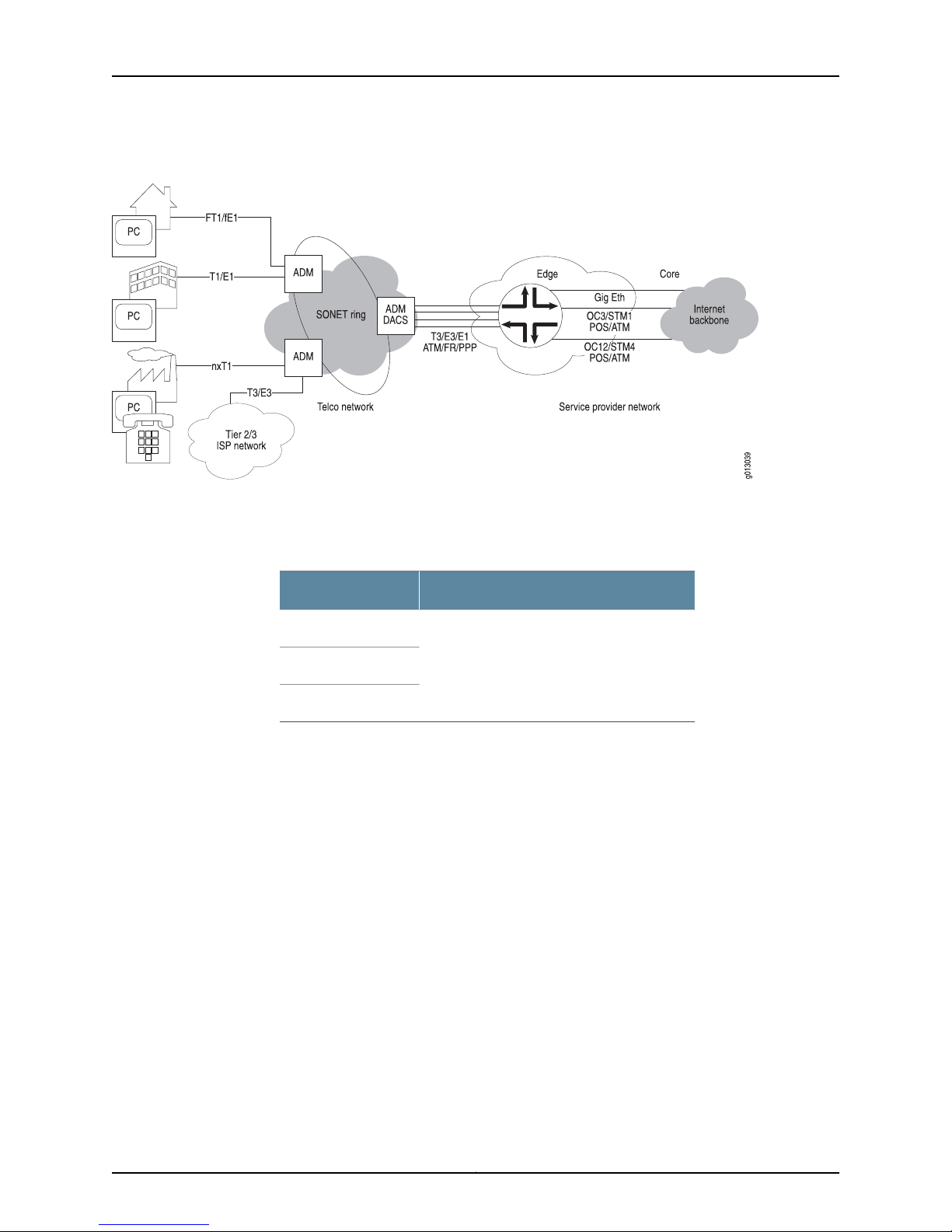
Figure 1: Private Line Aggregation with the E Series Router
The router supports a number of access and uplink methods; the most common pairings
are listed in Table 3 on page 5.
Chapter 1: Planning Your Network
Table 3: Common Access/Uplink Pairings
Frame Relay
ATM
xDSL Session Termination
The router supports Broadband Remote Access Server (B-RAS) applications, as shown
in Figure 2 on page 6. In this application, the router handles the aggregated output from
the digital subscriber line access multiplexers (DSLAMs). Directly connected to the
subscriber premises, theDSLAMs handle the coppertermination and aggregate the traffic
into a higher-speed uplink. The output from the DSLAM is fed into the router through a
DS3 or OC3 link.
UplinkAccess
ATM, Fast Ethernet, Gigabit Ethernet, or POSPPP
5Copyright © 2010, Juniper Networks, Inc.
Page 36
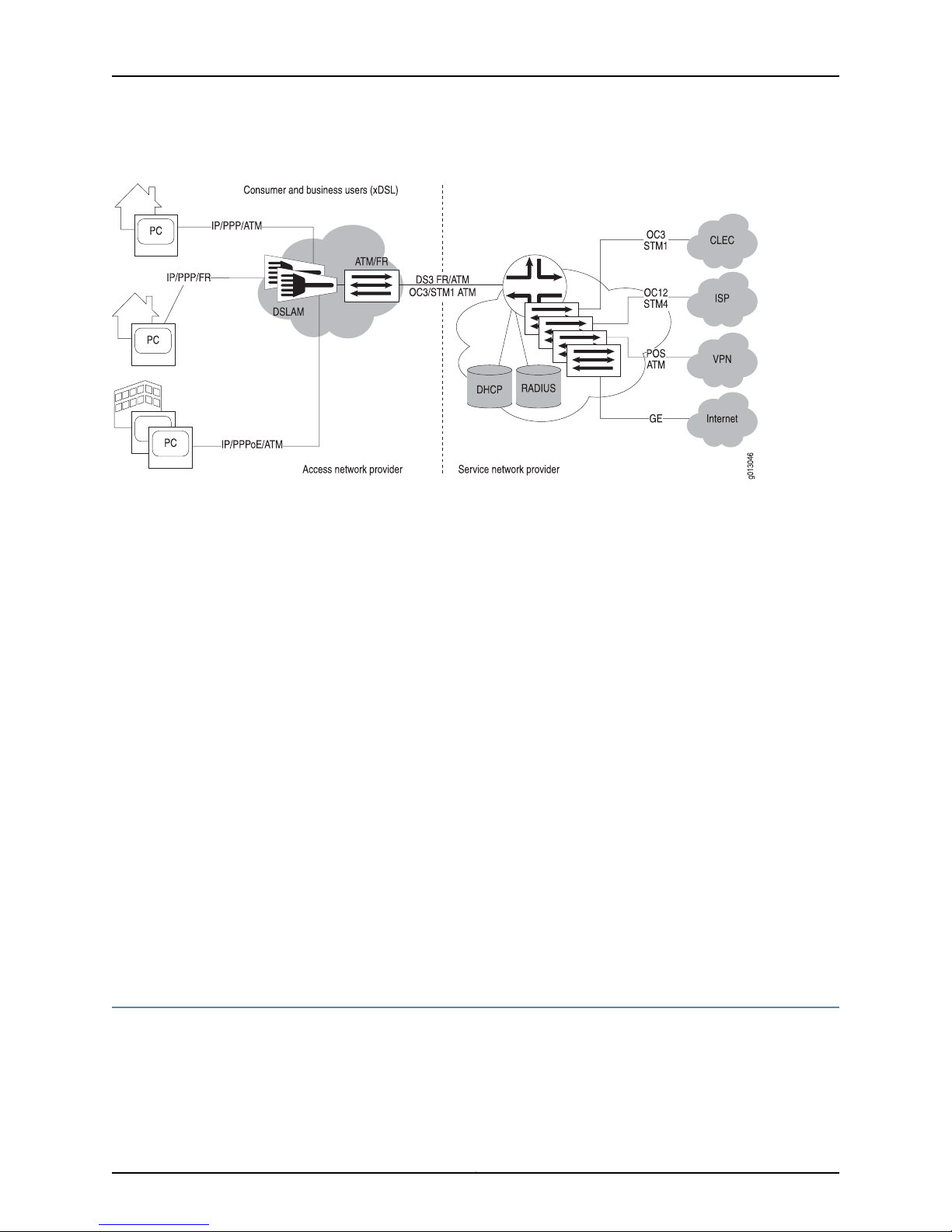
JunosE 11.3.x System Basics Configuration Guide
Figure 2: B-RAS Application
The router then performs several functions:
•
PPP session termination and authentication checking through PAP or CHAP
•
Coordination with DHCP servers and local IP pools to assign IP addresses
•
Connection to RADIUS servers or use of domain names to associate subscribers with
user profile information
•
Support for RADIUS accounting to gather detailed billing information
•
Application of the user profile to the user traffic flow, which could include QoS, VPN,
and routing profiles
The output of the router is typically a high-speed link, such as OC3/STM1 to feed a core
backbone router. Virtual routers can also be used to keep the traffic logically separate
and to direct packets to different destinations. As shown in Figure 2 on page 6, the
packets can be directed to a CLEC, ISP, corporate VPN, or the Internet.
A large number of xDSL protocols are supported, including:
•
IP/PPP/ATM
•
IP/PPP/Ethernet/ATM
•
IP/bridged Ethernet/ATM
See JunosE Broadband Access Configuration Guide, for information about configuring
B-RAS.
Layered Approach
The JunosE CLI enables you to configure your network based on the hierarchy of the OSI
model. Therefore, the JunosE configuration guides use a bottom-upapproach to describe
the configuration process. Figure 3 on page 7 shows the relationship of layers, protocols,
and interfaces to the configuration process. Software functions are layered on top of
Copyright © 2010, Juniper Networks, Inc.6
Page 37
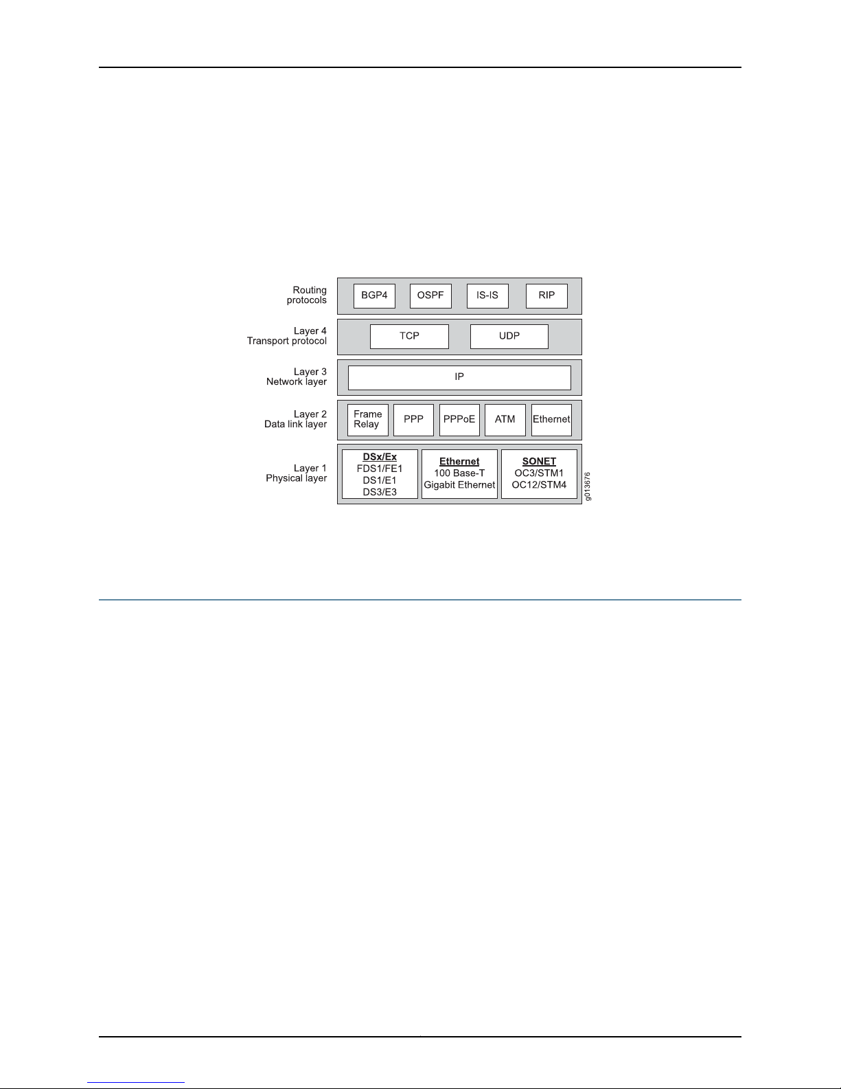
Chapter 1: Planning Your Network
physical (copper oroptical) interfaces. Therouter supportsa number of accessprotocols
(PPP/POS, Frame Relay, ATM) that allow service providers to offer a number of access
methods and line speeds to their subscribers. The router is optimized to handle IP
connections regardless of the access protocol used. The router also supports a number
of protocols that are specific to the B-RAS application. These are shown in Figure 3 on
page 7, and include IP/PPP/ATM and IP/PPP/Ethernet/ATM.
Figure 3: Network Configuration Using a Bottom-Up Approach
Layer 2 (data link) defines how the data is packaged and sent to an IP data connection
point in layer 3 (IP interfaces). In layer 3, you define the global attributes for IP services
that serve as a platform from which you add routing information.
Line Modules, I/O Modules, and IOAs
A range of line modules, I/O modules, andI/O adapters (IOAs) are available for therouter.
On the ERX14xx models, ERX7xx models, and the ERX310 router, most line modules pair
with a corresponding I/O module. On the E120 and E320 routers, a single line module
pairs with all available IOAs.
I/O modules and IOAs provide the input and output connections from the network to the
router. Line modules connect to their corresponding I/O modules or IOAs through a
passive midplane. A line module receives packets through its I/O module or IOA and
processes those packets. The router then routes the packets out to the network through
the designated I/O module or IOA.
Each line module, I/O module,and IOA has a labelon itsfaceplate. In thisdocumentation,
these modules areidentified by that label. For example, the high-density Gigabit Ethernet
line module has two ports, and is called the GE-HDE line module. Its corresponding I/O
modules are the GE-HDE I/O module and the GE-2 SFP I/O module.
When we refer to a related set of line modules, I/O modules, or IOAs, the generic
information from the modulelabels is used in this documentation. Forexample, theterm
“ OCx/STMx line modules” refers to both the OCx/STMx ATM and the OCx/STMx POS
line modules. Similarly, the term “ GE I/O modules” refers to both the GE Multimode I/O
module and the GE Single Mode I/O module.
7Copyright © 2010, Juniper Networks, Inc.
Page 38

JunosE 11.3.x System Basics Configuration Guide
For a complete list of the line modules and I/O modules available for ERX14xx models,
ERX7xx models, and the ERX310 router, see ERX Module Guide, Table 1, Module
Combinations. For more information aboutline modulesand IOAsavailablewith the E120
and E320 routers, see E120 and E320 Module Guide, Table 1, Modules and IOAs.
For more information about managing these modules, see “Managing Modules” on
page 341.
Interfaces
The term interfaces is used in avery specificway inthe JunosE CLI and thisdocumentation.
Interfaces are both physical and logical channels on the router that define how data is
transmitted to and received from lower layers in the protocol stack. Conceptually, you
configure an interface as part of the physical layer, layer 1.
For example, you can configure the physical and logical characteristics of T3 and T1 lines
coming directly fromthe customerpremises or from a central officeswitch and OC3 lines
going out to the core of your network infrastructure. These physical and logical
characteristics define an interface.
Subinterfaces
Interfacelayering mustalways be configured in order from the lowest layer to thehighest
layer. For example, if you have already configured IP to run over ATM and you want to
reconfigure the interface to run IP over PPP over ATM, you must first remove the IP
interface, apply PPP, and then reapply IP.
A subinterface is a mechanism that allows a single physical interface to support multiple
logical interfaces or networks. Several logical interfaces or networks can be associated
with a single physical interface. Configuring multiple virtual interfaces, or subinterfaces,
on a single physical interface allows greater flexibility and connectivity on the network.
Protocols such as Frame Relay and ATM require that you create one or more virtual
circuits over which your data traffic is transmitted to higher layers in the protocol stack.
The router requires that you define a subinterface on top of a physical interface as a
platform for a virtual circuit, such as a permanent virtual circuit (PVC).
Once you have defined the underlying characteristics of an interface, use the interface
command to:
1. Assign an interface type, such as POS or ATM.
2. Assign the associated interface specifier to the interface, such as the slot/port or
slot/adapter/port and channel/subchannel.
3. Assign one or more subinterfaces.
interface Command
The interface command has the following format:
interface interfaceType interfaceSpecifier
Copyright © 2010, Juniper Networks, Inc.8
Page 39

Each interface type has an interface specifier associated with it. The interface specifier
identifies the physical location of the interface on the router, such as the chassis slot and
port number, and logical interface information, such as a T1 channel on a channelized
T3 interface.
For detailed information about interface types and specifiers and for specific syntax for
the interface command, see the Interface Types and Specifiers in JunosE Command
Reference Guide.
General Configuration Tasks
The configuration process for E Series routers involves the following general tasks:
1. Determine IP-addressing information and information about the physical and logical
characteristics of the various interfaces that you want to configure.
2. Determine information about the link-layer protocols.
3. Determine how to organize virtual routers on the router.
4. Determine how IPSec will be used to provide security.
Chapter 1: Planning Your Network
5. Determine routing information that defines all or part of the network.
6. Create the virtual routers.
7. Configure the interfaces and subinterfaces (such as channelized T3, OCx/STMx, and
HDLC data channels) over which the higher-layer protocols run.
8. Configure the data link-layer protocols, such as Frame Relay, PPP, and ATM, that run
over these physical interfaces.
9. Configure the general IP information from which the other routing protocols will
operate.
10. Configure IP tunnels, shared interfaces, and subscriber interfaces.
11. Configure IPSec.
12. Configure the routing protocols that will run on the router, such as IP multicasting
protocols, OSPF, IS-IS, RIP, BGP-4, and MPLS.
13. Configure the Virtual Router Redundancy Protocol (VRRP) on IP/Ethernet interfaces.
14. Configure QoS and policy management.
15. Configure the router for remote access.
16. Use the appropriate show commands to display network activity on each of the
interfaces that you have configured. Do this to verify that they are operating as you
expect and to help improve the management of your network.
Configuring Virtual Routers
Multiple distinct virtual routers are supported within a single router, which allows service
providers to configure multiple, separate, secure routers within a single chassis. These
routers are identified as virtual routers (VRs). Applications for this function include the
9Copyright © 2010, Juniper Networks, Inc.
Page 40

JunosE 11.3.x System Basics Configuration Guide
creation of individual routers dedicatedto wholesale customers, corporate virtual private
network (VPN) users, or a specific traffic type.
The router implements the virtual routers by maintaining a separate instance of each
data structure for each virtual router and allowing each protocol to be enabled on a
case-by-case basis. Virtual routers provide full support for all supported routing protocols
(unicast, multicast, and MPLS).
For information about configuring virtual routers, see “Configuring Virtual Routers” on
page 525.
Configuring IPSec
IPSec provides security to IP flows through the use of authentication and encryption.
•
Authentication verifies that data is not altered during transmission and ensures that
users are communicating with the individual or organization that they believe they are
communicating with.
•
Encryption makes data confidential by making it unreadable to everyone except the
sender and intended recipient.
IPSec comprises two encapsulating protocols:
•
Encapsulating Security Payload (ESP) provides confidentiality and authentication
functions to every data packet.
•
Authentication header (AH) provides authentication to every data packet.
For information about configuring IPSec, see JunosE IP Services Configuration Guide.
Configuring Physical Layer Interfaces
The router supports a number of line rates; some of these are listed per line module
below.
•
COCX-F3 line module supports unchannelized E3.
•
Channelized OCx/STMx (cOCx/STMx) line module supports DS3 channelized to DS1,
fractional DS1, or the DS0 level; unchannelized DS3; E1/T1 channelized to fractional
DS1; unframed E1.
•
CT3 12-F0 line modules support DS3 channelized to DS1, fractional DS1, or the DS0
level. CT3 12-F0 line modules also support unchannelized T3.
•
IPSec Service module provides tunnel service for secure tunnels.
•
GE/FE line module supports Gigabit Ethernet and Fast Ethernet.
•
GE-2 line module and GE-HDE line module support Gigabit Ethernet.
•
OCx/STMx ATM line module supports OC3/STM1 ATM, OC12/STM4 ATM, and
unchannelized T3.
•
OCx/STMx POS line module supports OC3/STM1 POS and OC12/STM4 POS.
Copyright © 2010, Juniper Networks, Inc.10
Page 41
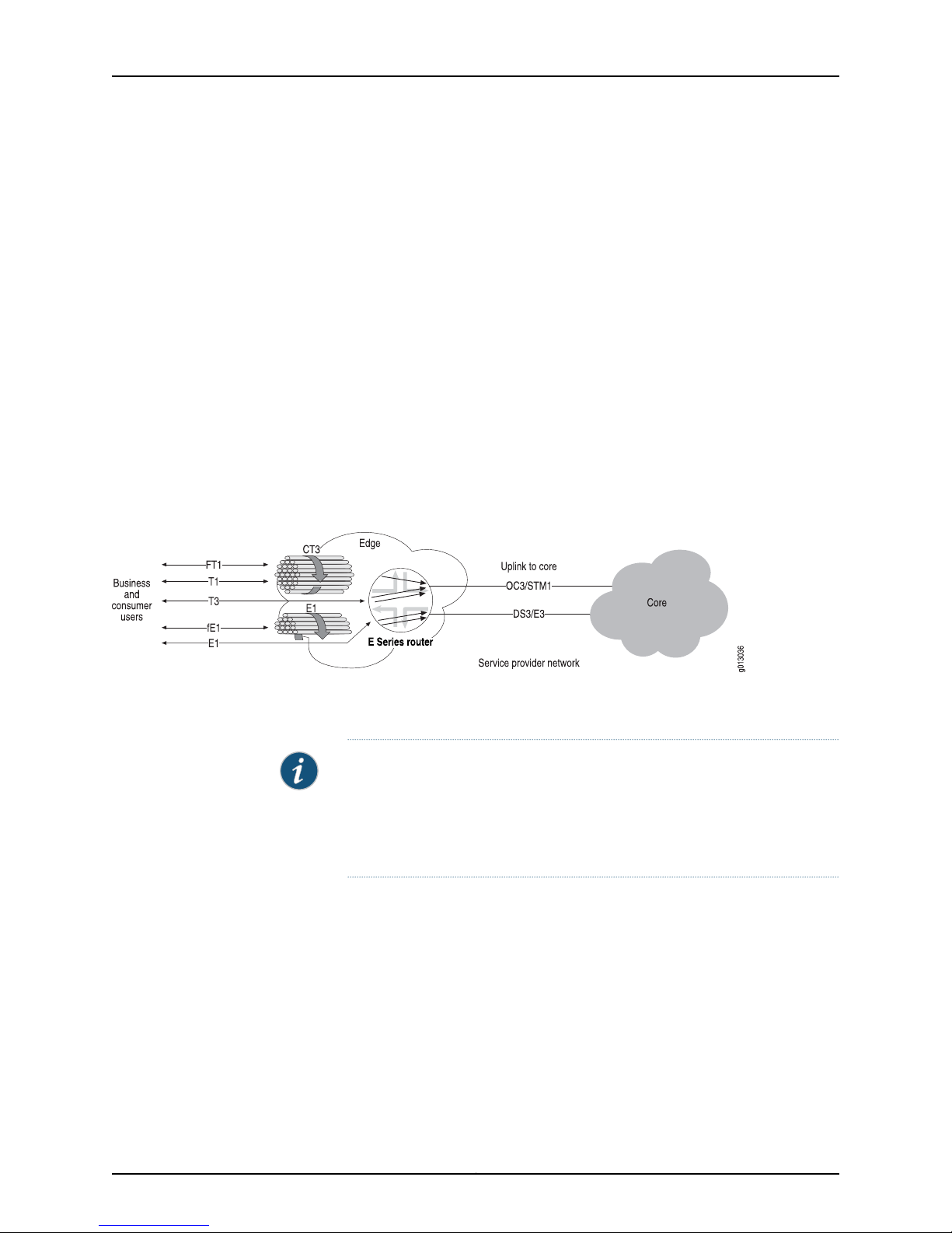
Chapter 1: Planning Your Network
•
OC48 line module supports OC48/STM16 POS.
•
OC3/STM1 GE/FE line module supports OC3/STM1 ATM and Gigabit Ethernet.
•
ES2 4G line module (LM) supports OC48/STM16 POS, OC12/STM1 POS, OC3/STM1
ATM, OC12/STM1 ATM, Gigabit Ethernet, 10-Gigabit Ethernet, and tunnel-service
interfaces.
•
ES2 10G Uplink LM, ES2 10G LM, and ES2 10G ADV LM supports 10-Gigabit Ethernet
interfaces.
•
COCX-F3 line module supports unchannelized T3.
•
Service Module (SM) provides tunnel service for IP tunnels and LNS termination.
A variety of protocols are supported over these interfaces, including IP/Frame Relay,
IP/ATM, IP/PPP, as well as the protocols to enable B-RAS services. The router’s DSx and
E1/E3 implementations supporttermination, statistics gathering, alarm surveillance,and
performance monitoring. These links can be used for either network ingress or network
egress.
Figure 4: E Series Router Support for Fractional T1/E1 Through T3/E3 Interfaces
Line Module Features
As shown in Figure 4 on page 11, the router can support fractional, full, and channelized
interfaces.
NOTE: See ERX Hardware Guide, Chapter 4, Installing Modules and E120 and
E320 Hardware Guide, Chapter 4, Installing Modules, for a discussion of slot
groups and modules. See the ERX Module Guide and the E120 and E320
Module Guide, for a discussion of the combination of line modules allowed
in E Series routers.
The following features are supported by the system line modules:
•
Three different clocking options: internal timing, loop timing, and chassis timing
•
DS3 framing type—Both M23 framing and C-bit parity
•
DS1 framing type—Both D4 framing mode and ESF framing mode
•
DS3 loopback—For line, payload, diagnostic, and DS1 loopbacks
•
DS1 loopback—For line, payload, and diagnostic loopbacks
11Copyright © 2010, Juniper Networks, Inc.
Page 42
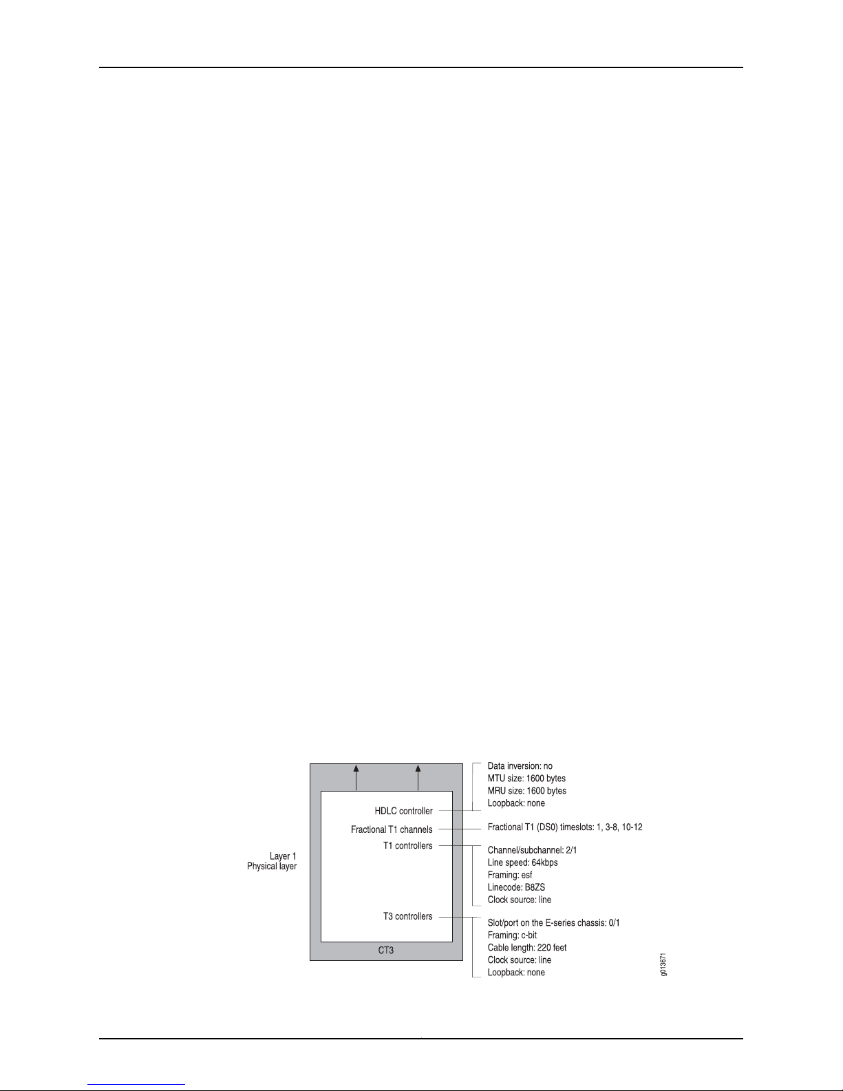
JunosE 11.3.x System Basics Configuration Guide
•
DS3/DS1 line status/alarm monitoring
•
DS1 line coding type—Both AMI line encoding and B8ZS line encoding
•
Unique IP interface support—For each PPP or Frame Relay PVC interface
Configurable HDLC Parameters
The following HDLC parameters are configurable:
•
Mapping of DS0 timeslots for T1/FT1 DS0 mapping
•
Setting the speed of the DS0 to Nx56 or Nx64
•
HDLC CRC checking (enable/disable)
•
HDLC CRC algorithm (CRC16 or CRC32)
•
Channel data inversion (enable/disable)
•
Maximum receive unit (MRU)
•
Maximum transmit unit (MTU)
Statistics are also gathered per line module.
Configuring Channelized T3 Interfaces
There12 T3 controllers available on each CT3 12-F0 line module. When you configure
these T3 controllers, you are actually configuring T3 (DS3) lines. Each T3 controller has,
by definition, 28 T1 controllers representing T1 (DS1) lines.
Use the T3 and T1 commands described in JunosE Physical Layer Configuration Guide, to:
•
Specify the line characteristics, such as framing format and clock source, for T3s and
associated T1s.
•
Assign full and fractional T1 channels (DS0) to a virtual channel.
Figure 5 on page 12 shows sample parameters for a channelized T3 interface
configuration.
Figure 5: Channelized T3 Interface Configuration Parameters
Copyright © 2010, Juniper Networks, Inc.12
Page 43
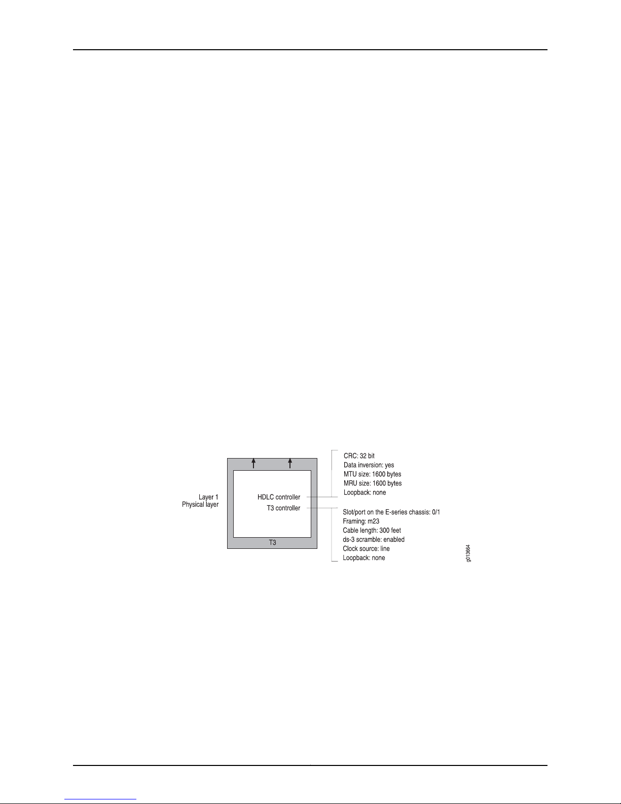
The following sample command sequence configures a serial interface for a
CT3 12-F0 module. See JunosE Physical Layer Configuration Guide, for details.
host1(config)#controller t3 0/1
host1(config-controll)#framing c-bit
host1(config-controll)#clock source line
host1(config-controll)#cablelength 220
host1(config-controll)#t1 2/1
host1(config-controll)#t1 2 framing esf
host1(config-controll)#t1 2 lineCoding b8zs
host1(config-controll)#t1 2/1 timeslots 2/1 1,3-8,10-12
host1(config-controll)#interface serial 0/1:2/1
Configuring T3 and E3 Interfaces
The COCX-F3 line module supports the following wide area network (WAN) protocol
encapsulations:
•
IP over PPP
•
IP over ATM
Chapter 1: Planning Your Network
•
IP over PPP over ATM
•
IP over PPP over PPPoE over ATM
•
IP over Frame Relay
Figure 6 on page 13 shows sample configuration parameters for a T3 interface
configuration.
Figure 6: T3 Interface Configuration Parameters
The following sample command sequence configures a serial interface for a T3 module.
See JunosE Physical Layer Configuration Guide, for details.
host1(config)#controller t3 0/1
host1(config-controll)#framing m23
host1(config-controll)#cablelength 300
host1(config-controll)#ds3-scramble
host1(config-controll)#exit
host1(config)#interface serial 0/1
host1(config-if)#invert data
host1(config-if)#mtu 1600
host1(config-if)#mru 1600
13Copyright © 2010, Juniper Networks, Inc.
Page 44
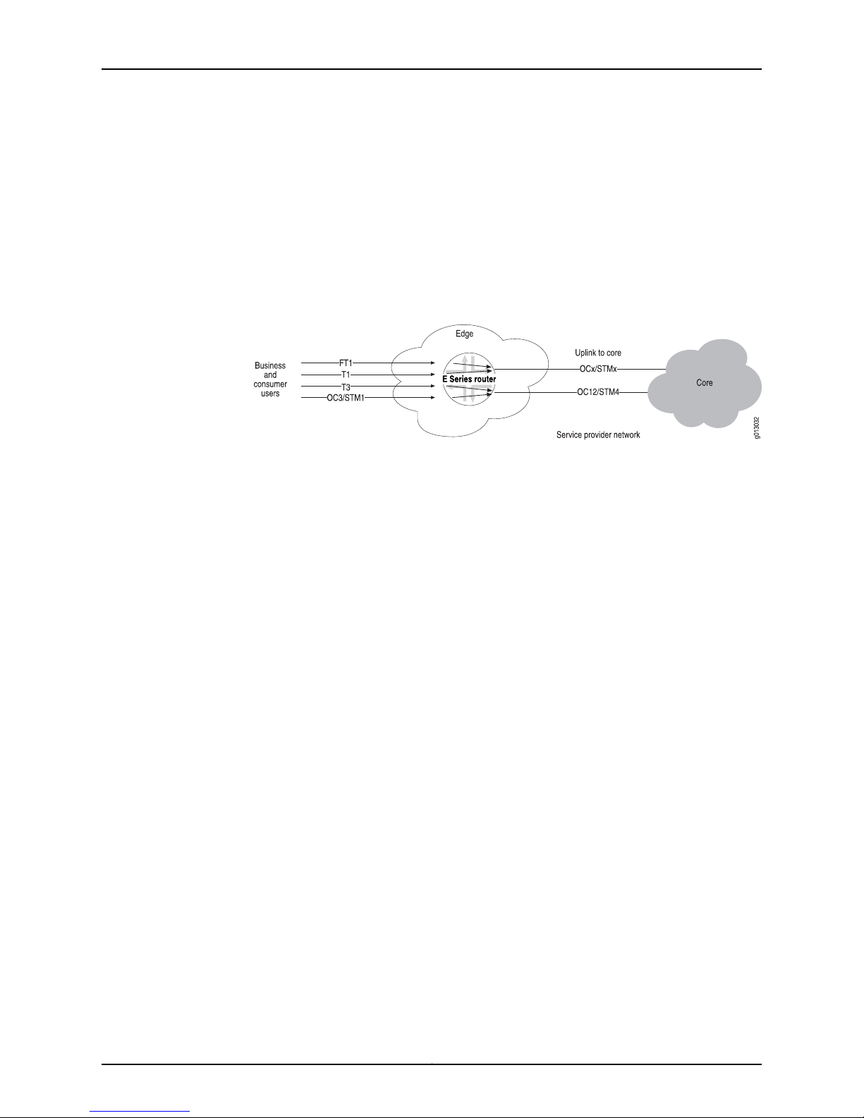
JunosE 11.3.x System Basics Configuration Guide
Configuring OCx/STMx and OC48 Interfaces
The router supports IP/ATM, IP/Frame Relay, and IP/PPP over SONET on the OCx/STMx
interfaces. OC48 interfaces support IP/Frame Relay and IP/PPP over SONET, but do not
support ATM operation. This interface support allows service providers toaccept incoming
optical connections or connect the router to the backbone network through optical
connections. The router’s SONETimplementationsupports termination, statistic gathering,
and alarm surveillance at the section, line, and path layers of a SONET interface.
Figure 7: SONET Interfaces
The following sample command sequence configures POS for an OC3 interface. See
JunosE Link Layer Configuration Guide, for details.
host1(config)#interface pos 0/1
host1(config-if)#encapsulation ppp
host1(config-if)#clock source internal module
host1(config-if)#loopback line
host1(config-if)#pos framing sdh
host1(config-if)#mtu 1600
host1(config-if)#mru 1600
host1(config-if)#pos scramble-atm
Configuring Channelized OCx/STMx Line Interfaces
The cOCx/STMx modules are generally used for circuit aggregration on the router. These
line modules supportthe followingcontrollersover OC3/STM1 or OC12/STM4, depending
on the I/O module used with the line module:
•
Fractional T1/E1 over SONET/SDH virtual tributaries or T3
•
Unframed E1
•
Unchannelized DS3
Figure 8 on page 15 shows theconfigurationparameters for a sample T1 over DS3interface
configuration.
Copyright © 2010, Juniper Networks, Inc.14
Page 45

Chapter 1: Planning Your Network
Figure 8: Parameters for T1 over DS3 Interface Configuration
The following sample command sequence configures T1 over DS3 on a channelized
SONET interface as described in Figure 8 on page 15. See JunosE Physical Layer
Configuration Guide, for details.
host1(config)#controller sonet 3/0
host1(config-controller)#path 12 oc1 4/1
host1(config-controller)#path 12 ds3 1 channelized
host1(config-controller)#path 12 ds3 1 t1 4
host1(config-controller)#path 12 ds3 1 t1 4/2 timeslots 1, 3-8, 10-12
host1(config)#interface serial 3/0:12/1/4/2
Configuring Ethernet Interfaces
Ethernet interfaces support IP, PPPoE, multinetting (multiple IP addresses), and VLANs
(subinterfaces). Ethernet modules use the Address Resolution Protocol (ARP) to obtain
MAC addresses for outgoing Ethernet frames and support quality of service (QoS)
classification. See JunosEPhysical Layer ConfigurationGuide, fora description of limitations
of individual modules.
Use the Fast Ethernet, Gigabit Ethernet, and 10-Gigabit Ethernet commands described
in JunosE Physical Layer Configuration Guide to:
•
Configure with IP only, with PPPoE only, with both IP and PPPoE, and with or without
VLANs.
•
Specify the line speed and duplex mode.
•
Specify the MTU.
The following sample command sequence configures an IP interface on a VLAN on an
Ethernet interface:
host1(config)#interface fastEthernet 2/0
host1(config-if)#encapsulation vlan
host1(config-if)#interface fastEthernet 2/0.1
15Copyright © 2010, Juniper Networks, Inc.
Page 46

JunosE 11.3.x System Basics Configuration Guide
host1(config-if)#vlan id 201
host1(config-if)#ip address 192.168.129.5 255.255.255.0
The following sample command sequence adds an IP interface over PPPoE to the same
VLAN:
host1(config)#interface fastEthernet 2/0.1.2
host1(config-if)#encapsulation pppoe
host1(config-if)#interface fastEthernet 2/0.1.2.1
host1(config-if)#encapsulation ppp
host1(config-if)#ip address 192.2.2.1 255.255.255.0
Configuring IPSec-Service Interfaces
IPSecService modules supportinterfacesassociatedwith secureIP tunnels.Youconfigure
and delete these interfaces statically;however, the router assigns tunnels to the interfaces
dynamically. This mechanism means that you must manage the interfaces for tunnels
manually; however, the router will add and remove tunnels when required.
For information about configuring secure IP interfaces, see JunosE IP Services Configuration
Guide . For information about managing IPSec service interfaces, see JunosE Physical
Layer Configuration Guide.
Configuring Tunnel Service Interfaces
You can configure both dynamic tunnels associated with L2TP and static IP tunnels on
your E Series router; however, you must first install a Service Module (SM). Dynamic
tunnels, which are not associated with a particular interface, are described in JunosE
Broadband Access Configuration Guide. Static tunnels, in which the tunnel is assigned to
a particular interfaceand specified in slot/port format, are described inJunosE IP Services
Configuration Guide.
For information about managing thesetypes oftunnels on the router, see JunosEPhysical
Layer Configuration Guide.
Configuring Data Link-Layer Interfaces
You can configure the following data link-layer interfaces:
•
IP/Frame Relay or multilink Frame Relay
•
IP/ATM
•
IP/PPP or multilink PPP
•
IP/Cisco HDLC
•
IP/Ethernet
Configuring IP/Frame Relay
The router supports IP over Frame Relay PVCs on the CT3 12-F0 and OCx/STMx POS
modules. The interface presented to the incoming traffic is an IP/Frame Relay router. In
addition, IP/PPP/Frame Relayis supportedon the T3 and E3 modules. With thisinterface,
the service provider can:
Copyright © 2010, Juniper Networks, Inc.16
Page 47
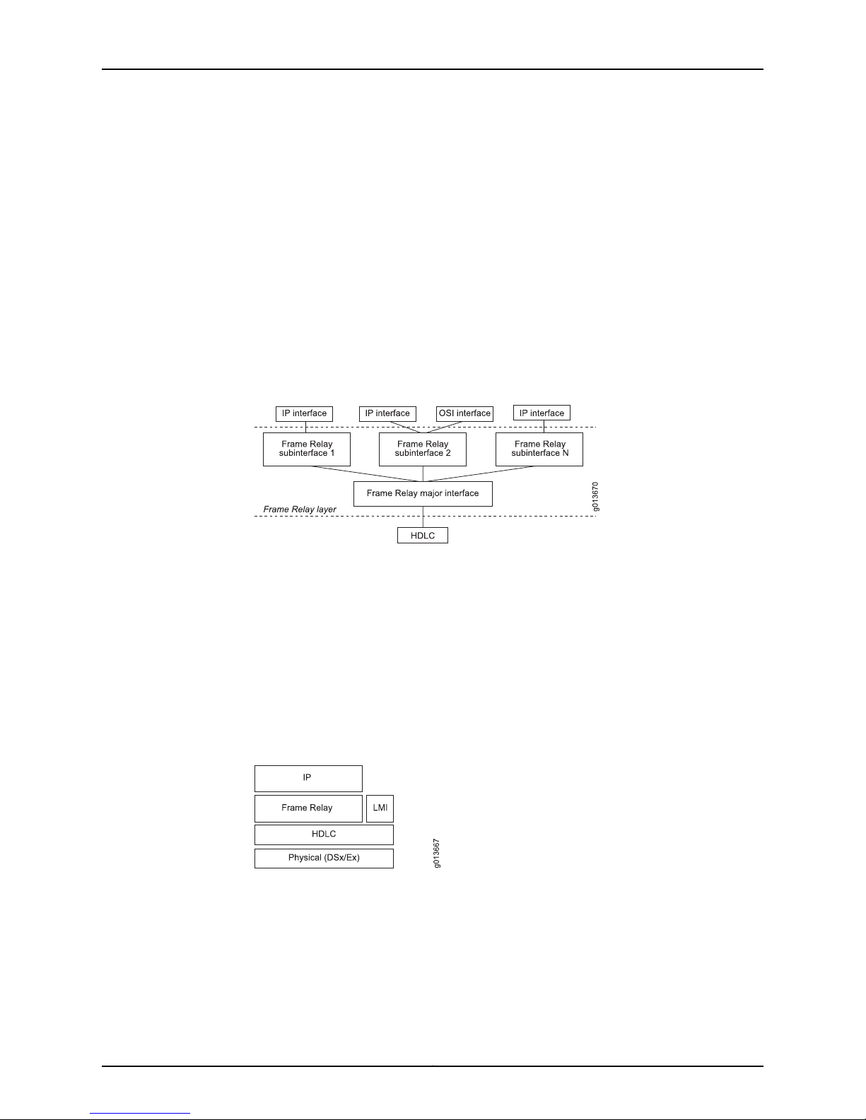
Chapter 1: Planning Your Network
•
Receive traffic from subscribers that have CPE equipment, such as routers with Frame
Relay interfaces
•
Take in traffic from other network devices that use Frame Relay, such as DSLAMs and
Frame Relay switches
•
Use Frame Relay as an uplink technology on an unchannelized T3 or E3 link
Figure 9 on page 17 shows the structure of the Frame Relay interface. Each Frame Relay
major interface sits on top of an HDLC interface. The Frame Relay implementation is
divided into two levels: a major interface and one or more subinterfaces. This division
allows a single physical interface to support multiple logical interfaces. Multiple IP
interfaces can also be assigned to each Frame Relay major interface through the
subinterfaces.
Figure 9: Frame Relay Interface Design
Figure 10 on page 17 shows the structure of the Frame Relay protocols with the physical
layer as the foundation. For Frame Relay, the physical layer can be channelized E1, E3,
channelized T1, T3, ora fractional service, assupported by the different line module ports.
The HDLC layer is on top of the physical layer and can support flexible assignment of
physical resources.
For example, an HDLC channel can support one DS0, a fractional T1, or an entire T1. The
major Frame Relay interface sits on top of the HDLC resource, and the subinterfaces sit
on top of the major interface. The Frame Relay subinterfaces connect to the IP interface
layer.
Figure 10: Structure of Frame Relay Protocols
The router supports Frame Relay LMI (local management interface) to provide the
operator with configuration and status information relating to the Frame Relay VCs in
operation. LMI specifies a polling mechanism to receive incremental and full-status
updates from the network. The router can represent either side of the User-to-Network
Interface (UNI) and supports unidirectional LMI. Bidirectional support for the
Network-to-Network Interface (NNI) is also supported.
17Copyright © 2010, Juniper Networks, Inc.
Page 48
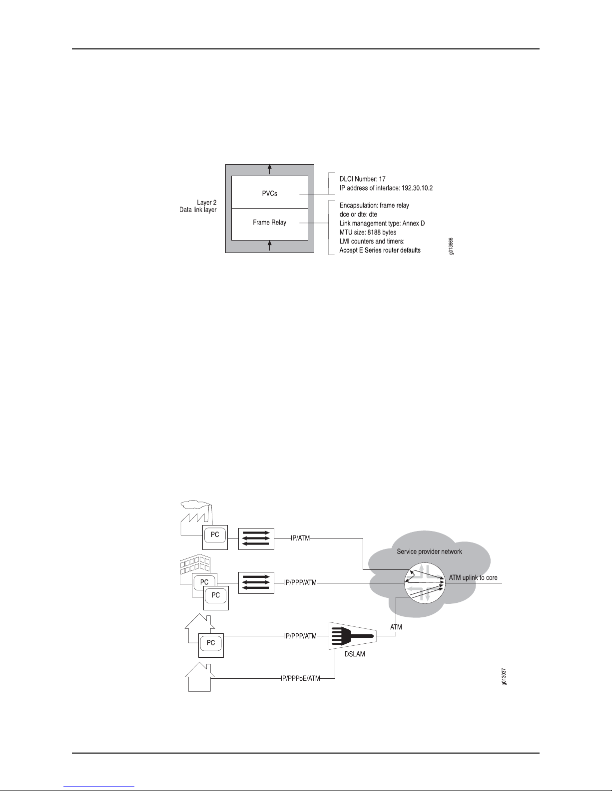
JunosE 11.3.x System Basics Configuration Guide
Figure 11 on page 18 shows sample configuration parameters for Frame Relay on a serial
interface.
Figure 11: Serial Interface Configuration Parameters for a Frame Relay
Connection
The following sample command sequence configures a serial interface for Frame Relay.
See JunosE Link Layer Configuration Guide, for information.
host1(config)#interface serial 0/1:1/5
host1(config-if)#encapsulation frame-relay ietf
host1(config-if)#frame-relay intf-type dte
host1(config-if)#frame-relay lmi-type ansi
host1(config-if)#interface serial 0/1:1/5.1
host1(config-subif)#frame-relay interface-dlci 17 ietf
host1(config-subif)#ip address 192.32.10.2 255.255.255.0
Configuring IP/ATM
The router supports IP over ATM PVCs on ATM line modules. This support allows service
providers to receive traffic from subscribers who have CPE equipment, such as routers
with ATM interfaces, to take in traffic from other network devices that use ATM, such as
DSLAMs, and to connect to service providers with ATM backbone structures.
Figure 12 on page 18 shows an IP/ATM access connection.
Figure 12: E Series Router IP/ATM Access Connection
Copyright © 2010, Juniper Networks, Inc.18
Page 49
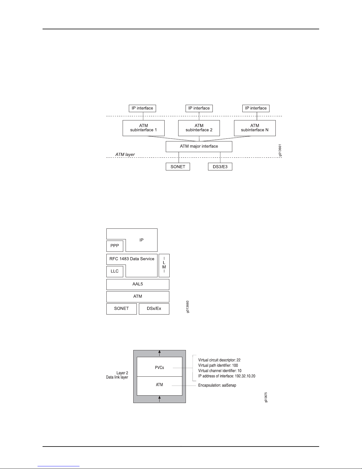
Chapter 1: Planning Your Network
Figure 13 on page 19 shows the structure of the ATM interface. For ATM, this can be
SONET, DS3, or E3 as supported by the different line modules. The major ATM interface
sits on top of the SONET/DS3/E3 resource, and the subinterfaces sit on top of the major
interface. The ATM subinterfaces connect to the IP interface layer.
Figure 13: Structure of the ATM Interface Design
Figure 14 on page 19shows thestructure of the ATM protocols. The physicallayer(SONET
and/or DSx/Ex) is the foundation and provider of layer 1 framing service. The ATM layer
is on top and provides cell, circuit, and OAM services. The AAL5 layer provides a
frame-oriented interface to the ATM layer. The integrated local management interface
(ILMI) provides local management across the UNI.
Figure 14: Structure of ATM Protocol
Figure 15 on page 19 shows sample configuration parameters for a typical ATM interface
configuration.
Figure 15: ATM Interface Configuration Parameters
19Copyright © 2010, Juniper Networks, Inc.
Page 50
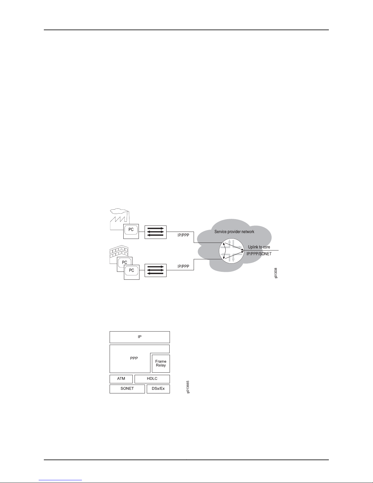
JunosE 11.3.x System Basics Configuration Guide
The following sample command sequence configures an ATM interface on port 0 of the
line module in slot 1. See JunosE Link Layer Configuration Guide, for information about
how to configure an ATM interface.
host1(config)#interface atm 0/1
host1(config-if)#interface atm 0/1.22
host1(config-if)#atm pvc 22 100 10 aal5snap
host1(config-subif)#ip address 192.32.10.20 255.255.255.0
Configuring IP/PPP
The router supports IP/PPP on the channelized T3, E1, and T3/E3 interfaces and
IP/PPP/SONET onthe OC3/STM1 and OC12/STM4interfaces. This support allows service
providers to accept traffic from subscribers who have CPE equipment, such as routers
with PPP interfaces, and to transmit traffic in PPP format to other network devices.
Figure 16 on page 20 shows that the router supports the incoming IP/PPP traffic from
the CPE. This traffic can then be routed to the uplink(s) attached to the router or to other
CPEs that are attached to the router.
Figure 16: IP/PPP Connections from the CPE on an E Series Router
As shown in Figure 17 on page 20, the PPP protocol can exist directly on top of the HDLC
layer or on top of a layer 2 Frame Relay or ATM interface. In either case, IP rides on top
of PPP, providing support for IP/PPP/ATM, IP/PPP/HDLC, and IP/PPP/Frame Relay.
Both SONET and DSx/Ex interfaces are supported at the physical layer.
Figure 17: Structure of PPP
Figure 18 on page 21 showssample configurationparametersfor PPPon a serial interface.
Copyright © 2010, Juniper Networks, Inc.20
Page 51

Configuring IP/HDLC
Chapter 1: Planning Your Network
Figure 18: PPP Interface Configuration Parameters
The following sample command sequence configures PPP on a serial interface. See
JunosE Link Layer Configuration Guide, for details.
host1(config)#interface serial 3/0:2/5
host1(config-if)#encapsulation ppp
host1(config-if)#ip address 192.32.22.10 255.255.255.0
The E Series router supports IP over Cisco HDLC on many types of serial interfaces. Cisco
HDLCmonitors linestatus ona serial interface by exchangingkeepalive request messages
with peer network devices. It also allows routers to discover IP addresses of neighbors
by exchanging Serial Link Address Resolution Protocol (SLARP) address request and
address response messages with peer network devices.
The E Series router Cisco HDLC is compatible with the Cisco Systems Cisco-HDLC
protocol, the default protocol for all Cisco serial interfaces.
The router supports the following framing features:
•
HDLC for data-link framing
•
18,000-byte information field size
Figure 19: Structure of Cisco HDLC Protocol
As shown in Figure 19 on page 21, the Cisco HDLC protocol can exist directly on top of
the HDLC layer or ATM or SONET interface. Both SONET and DSx/Ex interfaces are
supported at the physical layer.
The following example configures HDLC on a serial interface. See JunosE Link Layer
Configuration Guide , for details.
host1(config)#interface serial 3/1:2/1
host1(config-if)#encapsulation hdlc
host1(config-if)#ip address 192.32.10.2 255.255.255.0
21Copyright © 2010, Juniper Networks, Inc.
Page 52

JunosE 11.3.x System Basics Configuration Guide
Configuring IP/Ethernet
The E Series router supports IP/Ethernet. When you select an Ethernet interface, you can
assign an IP address to it, as the following example shows:
host1(config)#interface fastethernet 4/1
host1(config-if)#ip address 192.5.127.8 255.255.255.0
Figure 20 on page 22 shows an IP/Ethernet interface stack.
Figure 20: Example of IP over Ethernet Stacking Configuration Steps
Configuring IP Tunnels, Shared IP Interfaces, and Subscriber Interfaces
The E Series router supports IP tunnels, shared IP interfaces, and subscriber interfaces.
Configuring IP Tunnels
IP tunnels provide a way of transporting datagrams between routers separated by
networks that do not support all the protocols that those routers support. To configure
an IP tunnel, you mustfirst configure a tunnel-service interface. (See “Configuring Tunnel
Service Interfaces” on page 16.)
When you have configured a tunnel-service interface, treat it in the same way as any IP
interface on the router. For example, you can configure static IP routes or enable routing
protocols on the tunnel interface. The IP configurations that you apply to the tunnels
control how traffic travels through the network.
Configuring Shared Interfaces and Subscriber Interfaces
A shared IP interface is one of a group of IP interfaces that use the same layer 2 interface.
Shared IP interfaces are unidirectional—they can transmit but not receive traffic. A
subscriber interface is an extension of a shared IP interface. Subscriber interfaces are
bidirectional—they can both receive and transmit traffic.
You can create multiple shared IP interfaces over the same layer 2 logical interface—for
example, atm 5/3.101—enabling more than one IP interface to share the same logical
resources. This capability is useful, for example, when data received in one VRF needs
to be forwardedout aninterfacein another VRF, such as for BGP/MPLS VPNs(see JunosE
BGP and MPLS Configuration Guide, for more information).You canconfigure one or more
shared IP interfaces. Data sent over shared interfaces uses the same layer 2 interface.
You can configure shared interfaces as you would other IP interfaces. Each shared
interface has its own statistics.
The ESeries router supports subscriber interfaces on a particulartype of layer 2 interface,
Ethernet. In the absence of VLANS, Ethernet does not have a demultiplexing layer. A
Copyright © 2010, Juniper Networks, Inc.22
Page 53

subscriber interfaceadds a demultiplexing layer for anEthernet interface that is configured
without VLANs. Using subscriber interfaces, the router can demultiplex or separate the
traffic associated with different subscribers. You can use subscriber interfaces toseparate
traffic for cable modem subscribers withdifferent levels of service and to separate traffic
for VPNs.
For information aboutconfiguring shared interfaces and subscriber interfaces, see JunosE
IP, IPv6, and IGP Configuration Guide.
Configuring Routing Protocols
After you have set up the interfaces on which IP traffic flows, you can configure the
following routing protocols:
•
IP multicast protocols—IP multicasting allows a device to send packets to a group of
hosts, rather than to a list of individual hosts. Routers use multicast routing algorithms
to determine the best route and transmit datagrams throughout the network. See
JunosE Multicast Routing Configuration Guide, for information about how to configure
IP multicast.
Chapter 1: Planning Your Network
•
Open Shortest Path First (OSPF)—This interior gateway protocol (IGP) advertises the
states of network links within an autonomous system. An autonomous system is a set
of routers having a single routing policy running undera singletechnical administration.
See JunosE IP, IPv6, and IGP Configuration Guide , for information about howto configure
OSPF.
•
Integrated Intermediate System–to–Intermediate System (integrated IS-IS)—The
integrated IS-IS protocol provides routing for IP networks and is an extension of the
original IS-IS protocol, which provides routing for pure Open Systems Interconnection
(OSI) environments. This link-state protocol builds a complete and consistent picture
of a network’s topology by sharing link-state information across network devices in a
routing domain. A routing domain is a collection of contiguous networks that provide
full connectivity to all end systems located within them. See JunosE IP, IPv6, and IGP
Configuration Guide , for information about how to configure IS-IS.
•
Border Gateway Protocol (BGP)—BGP, an external gateway protocol (EGP), provides
loop-free interdomain routing between autonomous systems. See JunosE BGP and
MPLS Configuration Guide , for information about how to configure BGP.
•
Routing Information Protocol (RIP)—RIP is an IGP created for use in small,
homogeneous networks. RIP uses distance-vectorrouting torouteinformation through
IP networks. See JunosE IP, IPv6, and IGP Configuration Guide , for information about
how to configure RIP.
•
Multiprotocol Label Switching (MPLS)—MPLS is a hybrid protocol that integrates
network layer routing with label switching to provide a layer 3 network with traffic
management capability. Traffic engineering enables more effective use of network
resources while maintaining high bandwidth and stability. MPLS enables service
providers to offer their customers the best service available given the provider’s
resources. There are two fundamental aspects to MPLS:
•
Label distribution—The set of actions MPLS performs to establish and maintain a
label-switched path (LSP), also known as an MPLS tunnel.
23Copyright © 2010, Juniper Networks, Inc.
Page 54

JunosE 11.3.x System Basics Configuration Guide
•
Data mapping—The process of getting data packets onto an established LSP.
See JunosE BGP and MPLS Configuration Guide , for information about configuring
MPLS.
In addition, if you want to make configuration adjustments to IP, see JunosE IP, IPv6, and
IGP Configuration Guide, for details.
Configuring VRRP
The Virtual RouterRedundancy Protocol (VRRP) can prevent lossof networkconnectivity
to end hosts if the static default IP gateway fails. By implementing VRRP, you can
designate a number of routers as “ backup” routers in case the default “ master” router
fails. You can configure VRRP on IP/Ethernet interfaces.
For information about configuring VRRP, see JunosE Services Availability Configuration
Guide.
Configuring Routing Policy
Configuring QoS
The router supports a number of features that allow the service provider to control the
exchange of routing information between virtual routers in the router, between routers
in the network, and between protocols within a router:
•
Accesslists—Provide filters thatcan be applied to route maps or distribution lists. They
allow policies to be created, such as a policy to prevent forwarding of specified routes
between the BGP-4 and IS-IS routing tables.
•
Route maps—Modify the characteristics of a route (generally to set its metric or to
specify additional attributes) as it is transmitted or accepted by a router. Route maps
can use access lists to identify the set of routes to modify.
•
Distribution lists—Control the routing information that is accepted or transmitted to
peer routers. Distribution lists always use access lists to identify routes for distribution.
For example, distribution lists could use access lists to specify routes to advertise.
•
Redistribute routes—Allow routes to be shared between routing protocols and routing
domains. For example, a subset of BGP-4 routes could be leaked into the IS-IS routing
tables.
See JunosE IP Services Configuration Guide, for details.
QoS is a suite of features that configure queuing and scheduling on the forwarding path
of your E Series router. QoS provides a level of predictability and control beyond the
best-effort service that is the E Series router’s default data delivery service. Packets not
assigned to a specific traffic class are carried in the best-effort traffic class. Best-effort
service provides packet transmission with no guarantee of results.
The major QoS features that the E Series router provides are:
Copyright © 2010, Juniper Networks, Inc.24
Page 55

•
Multiple traffic classes
•
Configurable scheduling
•
Configurable buffer management
For information about configuringQoS, see JunosE Quality of Service Configuration Guide.
Configuring Policy Management
Policy management allows network service providers to implement packet forwarding
and routing specifically tailored to their customer’s requirements. Using policy
management, customers can implement policies that selectively cause packets to take
different paths. Policy management provides several types of services:
•
Policy routing—Predefines packet flow to a destination port or IP address
•
QoS classification and marking—Marks packets of a packet flow.
•
Packet forwarding—Allows forwarding of a packet flow.
•
Packet filtering—Drops packets of a packet flow.
Chapter 1: Planning Your Network
•
Packet logging—Logs packets of a packet flow.
•
Ratelimiting—Enforces line ratesbelow thephysical line rate ofthe port andsets limits
on packet flows.
•
RADIUS policy support—Allows you to attached a preconfigured policy to an interface
through RADIUS.
See JunosE Policy Management Configuration Guide, for details about configuring policy
management.
Configuring Remote Access
The E Series router supports the following remote access functionality:
•
Broadband Remote Access Server (B-RAS)—This application runs on the router and
is responsible for:
•
Aggregating the output from DSLAMs
•
Providing user PPP sessions and PPP session termination
•
Enforcing QoS policies
•
Routing traffic into an ISP’s backbone network
See JunosE Broadband Access Configuration Guide.
•
Layer 2 Tunneling Protocol (L2TP)—A method of encapsulating layer 2 packets, such
as PPP, for transmission across a network. In an L2TP relationship, an L2TP access
concentrator (LAC) forms a client-server relationship with a destination, known as an
L2TP network server (LNS), on a remote network.
25Copyright © 2010, Juniper Networks, Inc.
Page 56

JunosE 11.3.x System Basics Configuration Guide
You can configure the router to act as an LAC in PPP pass-through mode. The router
creates tunnels dynamically by using AAA authentication parameters and transmits
L2TP packets to the LNS through IP/UDP. See JunosE Broadband Access Configuration
Guide.
•
Non-PPP equal access—A method of allowing remote access in which the router
provides IP addresses to subscribers’ computers through Dynamic Host Configuration
Protocol (DHCP). This method is particularly convenient for broadband (cable and
DSL) environments or environments that use bridged Ethernet over ATM, because
network operators can support one central system rather than an individual PPPoE
client on each subscriber’s computer. See JunosE Broadband Access Configuration
Guide.
Copyright © 2010, Juniper Networks, Inc.26
Page 57

CHAPTER 2
Command-Line Interface
This chapter provides information about the E Series router command-line interface
(CLI).
This chapter contains the following sections:
•
Overview on page 27
•
Platform Considerations on page 45
•
Accessing the CLI on page 45
•
CLI Command Privileges on page 49
•
Using Help on page 60
•
Using Command-Line Editing on page 63
•
Accessing Command Modes on page 66
Overview
Command Modes
The CLI is the interface to the software that you use whenever you access the
router—whether from the console or through a remote network connection. The CLI,
which automatically starts after the router finishes booting, provides commands that
you use to perform various tasks, including configuring theJunosE Software and monitoring
and troubleshooting the software, network connectivity, and the router hardware.
Managing your router using the CLI gives you access to thousands of commands. The
router’s CLI uses an industry de facto standard look and feel, which might be familiar to
you. If you are new to this CLI, it is helpful to read this entire chapter, where you can learn
about CLI shortcuts and other helpful information.
Command modes set a context for the CLI. Each command in the CLI is available from
one or more command modes. From some command modes you can only view router
information; from others you can perform configuration tasks. For example, you can
access User Exec mode to display information and then access Global Configuration
mode to set parameters or enable a particular feature. By recognizing the command-line
prompt, you can identify where you are in the CLI at any given point. When you can easily
identify where you are, it is easy to get to where you want to be.
27Copyright © 2010, Juniper Networks, Inc.
Page 58
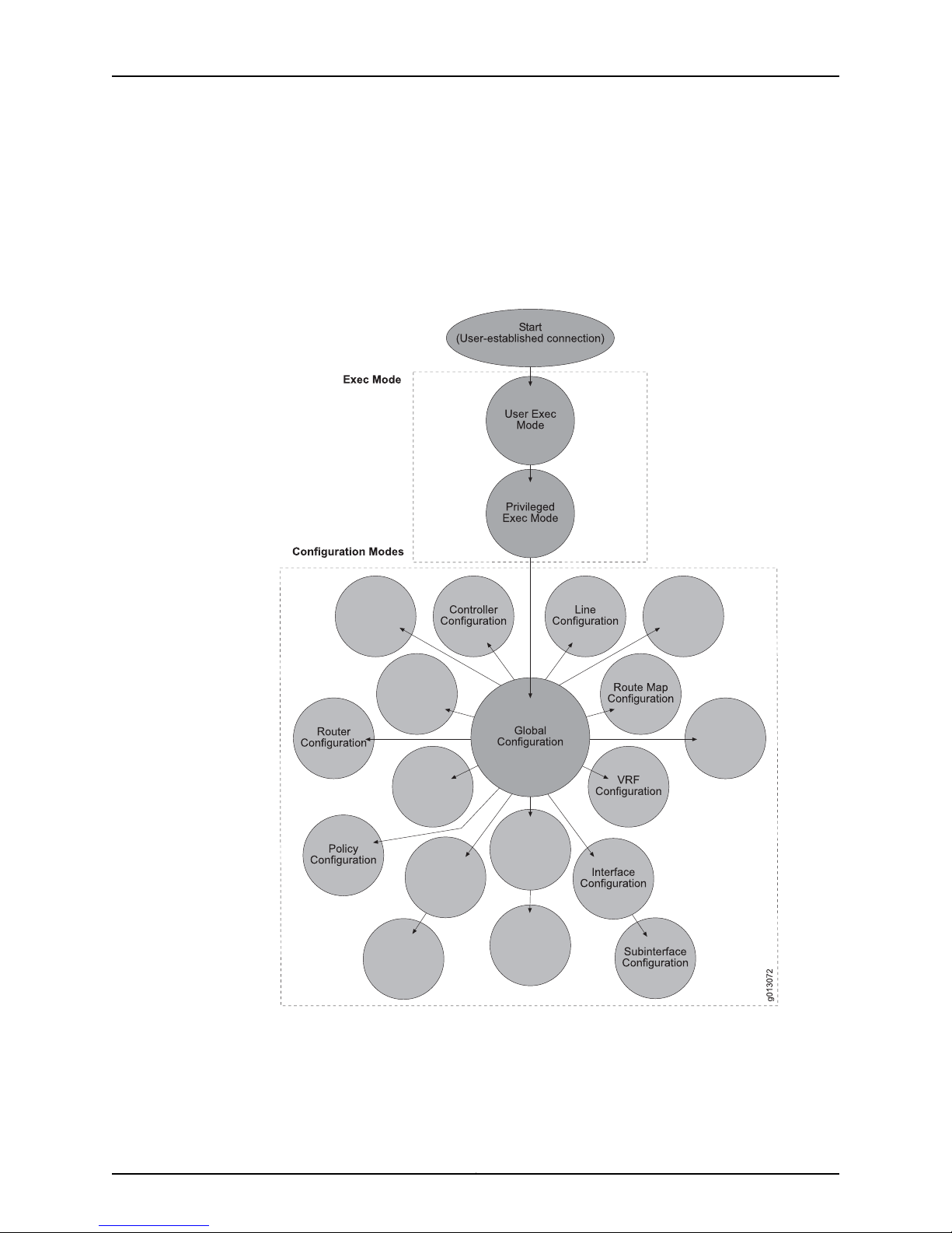
JunosE 11.3.x System Basics Configuration Guide
Figure 21 on page 28illustrates the command mode architecture. Only some of the many
configuration modes are shown.
Command modes are discussed in greater detail in the section “Accessing Command
Modes” on page 66 . See the JunosE Command ReferenceGuide to find related command
modes for any command.
Figure 21: Command Mode Architecture
Command-Line Prompts
Within the CLI, thecommand-line promptidentifies boththe hostname and the command
mode. The hostname is the name of your router; the command mode indicates your
location within the CLI system.
Copyright © 2010, Juniper Networks, Inc.28
Page 59

For example:
Keywords and Parameters
CLI commands are made up of two primary elements: keywords and parameters.
Keywords
Every command requires at least one keyword; however, a command can contain other
optional keywords. The keyword(s) must be typed into the CLI accurately for it to be
recognized. These are examples of keywords:
Chapter 2: Command-Line Interface
reload
run
router
map-class
map-list
clear ip isis redistribution
show vlan subinterface
qos-port-type-profile
no rtr reset
radius calling-station-delimiter
You can abbreviate keywords; however, you must enter enough initial characters to
unambiguously identify the command. For example, if the keyword you want to specify
is map-class and you enter only map-, an error appears. The error indicates that one or
more possible keywords begin with map-, thus making your entry ambiguous.
Parameters
Parameters are often required elements of a command; however, for some commands,
parameters are not required. A parameter is most often a value that you specify after
the keyword. There are different types of parameters, such as strings, integers, or IP
addresses.
The CLI indicates the type of parameter that you must enter. When you see a range of
numbers or uppercase letters, it indicates that you must specify a value. For example:
Sample Parameter User InputCLI Parameter Placeholder or Range
charlie:1234ROUTER[:VRF]
3/2:20/15INTERFACE
29Copyright © 2010, Juniper Networks, Inc.
Page 60

JunosE 11.3.x System Basics Configuration Guide
Keywords and Parameters Together
By combining keywords and parameters in the correct sequence, youcan begin using the
CLI to configure and monitor your router. For example, you could specify the command
hostname to change the name of your router by entering a keyword and a parameter.
You need to type only the portion of the keyword that makes it unambiguous, such as
hostn. Here, the value of the parameter, which is the name you assign to the host, is a
string of up to 64 characters.
Sample Parameter User InputCLI Parameter Placeholder or Range
windtunnelWORD
5600<0–4294967295>
192.56.32.2A.B.C.D
Using CLI Commands
When you enter this command, the new hostname appears in the prompt.
Another example is a command that requires you to enter a number from within a given
range. The command ip http port requires that a value be entered for the portNumber
parameter. The value of this parameteris a number in therange of 0–65535. Forexample,
you could enter:
juniper(config)#ip http port 56789
NOTE: You can find detailed information about command syntax, with
parameter values defined, in the JunosE Command Reference Guide.
This section introduces some useful shortcuts and command-related highlights. These
include:
•
Abbreviated Commands on page 31
•
The ? Key on page 31
•
Backspace or Delete on page 31
•
Enter on page 31
•
Tab on page 32
•
Arrow Keys on page 32
•
The no Version on page 32
Copyright © 2010, Juniper Networks, Inc.30
Page 61

Chapter 2: Command-Line Interface
•
run and do Commands on page 33
•
show Commands on page 34
•
Redirection of show Command Output on page 38
•
Regular Expressions on page 39
•
The - -More- - Prompt on page 40
•
Responding to Prompts on page 43
Abbreviated Commands
Remember, you can abbreviatekeywordsto save time ifyou enterat least enoughleading
characters to uniquely identify the desired keyword. For example:
host1(config-if)#ip re
This abbreviation is for the command ip redirects. The string ip re is enough information
for the CLI toidentify thecommand youare using. See the section “Using Help” on page 60
for additional information.
The ? Key
Use the ? key at any time to see all the choices you can enter next. For example:
host1(config)#router ?
bgpConfigure the Border-Gateway Protocol (BGP)
isisConfigure ISO IS-IS
ospfConfigure the Open Shortest Path First protocol (OSPF)
ripConfigure the Routing Information Protocol
host1(config)#router
When you enter the ? character, all available choices are displayed. The router again
displays the command you typed. You then have to type in only the choice you want and
press Enter.
A <cr> in the list of choices means that you can press Enter to execute the command.
For example:
host1(config-if)#isis metric 40 level-2 ?
<cr>
host1(config-if)#isis metric 40 level-2
NOTE: If the list of options extends beyond one screen, the last line on your
screen displays the --More-- prompt. If you want to use the ? character as
part of a string, such as a hostname or a regular expression, you must enter
the following key sequence: Ctrl+v+?. Otherwise, the CLI considers the ? to
be a request for assistance in completing the command.
Backspace or Delete
Use either key to delete the character immediately preceding the cursor.
Enter
Always use this key to execute the command you entered.
31Copyright © 2010, Juniper Networks, Inc.
Page 62

JunosE 11.3.x System Basics Configuration Guide
Tab
Use this key to complete the current keyword. For example, if you entered a portion of a
lengthy command, such as
host1(config)#class
and press Tab, the full name of the command appears:
host1(config)#classifier-list
Arrow Keys
Some terminals have arrow (or cursor) keys on their keyboards. These arrow keys are
very useful; however, to use them you must have an ANSI/VT100 emulating terminal.
The UpArrow and Down Arrow keys display command history.The Up Arrow key displays
the previous command; you can also use Ctrl+p. The Down Arrow key displays the next
command; you can also use Ctrl+n.
The Left Arrow and Right Arrow keys allow the user to move the cursor back and forth
in the command line.
The no Version
With very few exceptions, every system configuration command has a no version, which
you can use to negate a command (or aportion of it as specified by an optional keyword)
or to restore its default setting. When you use a command without the keyword no, you
can reenable a disabled feature or override a default setting.
You have the option of using the default keyword whenever the no keyword is also a
choice; simply enter the keyword default instead of no.
In most cases, when you execute the default version of a command, it produces the
exact results as the no version. There are some commands for which the default version
yields a different result from the no version.
Commands for which the default behavior differs from the no behavior are clearly
identified inthe JunosECommand Reference Guide. Unless otherwise specified,therefore,
the default command is identical to the no command and is neither documented nor
discussed.
The syntax for each no command is described in the JunosE Command Reference Guide.
The few system configuration commands that do not have a no version are indicated in
the individual command description.
Because show commands are for the purpose of monitoring your configurations, they
do not have no versions. Most User Exec and Privileged Exec mode commands do not
have no versions.
The CLI can act onno versionsof commandswhen youhave entered sufficient information
to distinguish the command syntactically; the CLI ignores all subsequent input on that
line.
Copyright © 2010, Juniper Networks, Inc.32
Page 63

Chapter 2: Command-Line Interface
To be compatible with some non-Juniper Networks implementations, the no versions of
commands will accept the same options as the affirmative version of the commands.
The CLI ignores the optional input if it has no effect on the command behavior. If using
the option changes the behavior of the no version, the individual command entry in this
guide describes the difference in behavior.
run and do Commands
You can run Exec mode commands while in any configuration mode by preceding the
command with the keyword run or do. For example:
host1(config)#run show users
NOTE: The run and do commands are interchangeable.
By using the run or do command in this way, you can obtain showcommand information
without leaving configuration mode.
The only commands that cannot be preceded by run or do are the configure command
and those commands that are already available in all modes, such as sleep or exit.
Example 1 host1(config)#run show config | begin interface
interface null 0
!
interface fastEthernet 0/0
ip address 10.6.129.41 255.255.128.0
!
interface gigabitEthernet 5/0
!
interface atm 6/0
interface atm 6/0.1 point-to-point
encapsulation pppoe
!
interface atm 6/0.1.7
!
interface atm 6/0.1.5
!
interface atm 6/0.1.2
!
interface atm 6/0.1.9
!
interface atm 6/0.1.11
!
interface atm 6/0.1.15
!
interface atm 6/0.1.18
!
ip route 0.0.0.0 0.0.0.0 10.6.128.1
ip route 10.10.121.72 255.255.255.255 10.6.128.1
!
!
route-map adsf permit 10
router dvmrp
!
router igmp
!
33Copyright © 2010, Juniper Networks, Inc.
Page 64

JunosE 11.3.x System Basics Configuration Guide
snmp-server community private view everything rw
snmp-server contact Mary
snmp-server
!
! End of generated configuration script.
host 1(config)#int fa 0/0
Example 2 host1(config-if)#do dir
Please wait...
unshared in
file size size date (UTC) use
------------------ -------- -------- ------------------- --reboot.hty 31040 31040 10/30/2001 15:31:10
system.log 20481 20481 10/26/2001 17:24:16
soft_clear_in.mac 8578 8578 10/24/2001 14:39:02
erx_3-3-1.rel 71082105 71082105 10/25/2001 13:02:50 !
erx_3-3-1.rel 70502991 70502991 10/24/2001 19:58:08
autocfg.scr 355 355 09/28/2001 13:33:04
Capacity = 224133120, Bytes Free = 44986177, Reserved = 36700160
host1(config-if)#
show Commands
You have access to a variety of show commands that display router and protocol
information. You can filter the output of a show command by specifying | (the UNIX pipe
symbol), one of thefollowingkeywords,and either a case-sensitive text string or a regular
expression.
•
begin—Displays output beginning with the first line that contains the text string or
regular expression
•
include—Displays output lines that contain the text string or regular expression and
excludes lines that do not contain the text string or regular expression
•
exclude—Displays output lines that donot contain the text string or regular expression
and excludes lines that do contain the text string or regular expression
For a list of regular expressions, see “Regular Expressions” on page 39. You can press
Ctrl+c to interrupt the show command output.
NOTE: The system does not recognize beginning spaces of the text string.
For example, if you enter include IP as the text string on which to filter, the
system ignores the space and displays lines that include words such as RIP.
Example 1 In the following example, the output display starts with the first line that contains the
string inter. The system omits all the preceding lines of the output from the display
because none of them contains the string inter.
host1#show config include-defaults | begin inter
Please wait...log verbosity low internalNetwork
log verbosity low ipEngine
log verbosity low ipProfileMgr
log verbosity low ipProfileMgrEngineering
no log engineering
log fields timestamp instance no-calling-task
Copyright © 2010, Juniper Networks, Inc.34
Page 65

!
timing select primary
timing source primary internal
timing source secondary internal
timing source tertiary internal
!
no disable-autosync
no disable-switch-on-error
no redundancy lockout 0
!
virtual-router default
ip domain-lookup
ip name-server 10.2.0.3
ip domain-name 789df
!
host f 10.10.133.11 ftp anonymous null
interface null 0
interface ip 0/0
arp timeout 21600
!
interface ip 2/0
arp timeout 21600
!
interface ip s10
arp timeout 21600
!
interface atm 2/0
no shutdown
atm sonet stm-1
loopback line
atm uni-version 3.0
atm oam loopback-location 0xFFFFFFFF
atm vc-per-vp 32768
atm vp-tunnel 1 10
load-interval 300
no atm snmp trap link-status
no atm shutdown
!
no atm aal5 snmp trap link-status
no atm aal5 shutdown
!
interface atm 2/0.1 point-to-point
no shutdown
no atm atm1483 shutdown
no atm atm1483 snmp trap link-status
!
ip route 0.0.0.0 0.0.0.0 10.13.5.1
ip debounce-time 0
ip source-route
!
router ospf 5
no ospf shutdown
ip route-type both
timers spf 3
maximum-paths 4
ospf auto-cost reference-bandwidth 100
distance ospf intra-area 110
distance ospf inter-area 112
distance ospf external 114
! Area 0.0.0.0
!
Chapter 2: Command-Line Interface
35Copyright © 2010, Juniper Networks, Inc.
Page 66

JunosE 11.3.x System Basics Configuration Guide
! Trap Source: <not configured>
! Note: SNMP server not running.
!
host1#
Example 2 In the following example, the output display consists only of lines that contain the string
ip. The system omits all other lines of the output from the display because none of them
contains the string ip.
host1#show config include-defaults | include ip
! Configuration script generated on WED JUN 06 2001 02:17:00 UTC
strip-domain disable
Please wait...log verbosity low ipEngine
log verbosity low ipEngineering
log verbosity low ipGeneral
log verbosity low ipInterface
log verbosity low ipNhopTrackerEngineering
log verbosity low ipNhopTrackerGeneral
log verbosity low ipProfileMgr
log verbosity low ipProfileMgrEngineering
!
bandwidth oversubscription
ip domain-lookup
ip name-server 10.2.0.3
ip domain-name 789df
interface ip 0/0
interface ip 2/0
interface ip s10
ip address 10.13.5.61 255.255.255.0
no ip proxy-arp
no ip directed-broadcast
ip redirects
ip route 0.0.0.0 0.0.0.0 10.13.5.1
ip debounce-time 0
ip source-route
no ip ftp source-address
type echo protocol ipIcmpEcho 10.5.0.200 source fastEthernet0/0
type pathEcho protocol ipIcmpEcho 10.2.0.3
type echo protocol ipIcmpEcho 10.5.0.11 source-ipaddr 10.13.5.61
!
controller t1 6/0
framing esf
lineCoding b8zs
clock source line
cablelength short 0
no remote-loopback
!
log engineering
log verbosity low
no log severity
log verbosity low NameResolverLog
log verbosity low atm
log verbosity low atm1483
log verbosity low atmAal5
log verbosity low bgpConnections
log verbosity low bgpDampening
!
host1#
Copyright © 2010, Juniper Networks, Inc.36
Page 67

Chapter 2: Command-Line Interface
Example 3 In the following example, the output display consists only of lines that do not contain
the string !. The system omits all other lines of the output from the display because each
line contains the string !.
host1#show config include-defaults | exclude !
boot config running-configuration
boot system 3-3-1.rel
no boot backup
no boot subsystem
no boot backup subsystem
boot revert-tolerance 3 1800
no boot force-backup
aaa domain-map jacksonville
virtual-router miami
strip-domain disable
aaa domain-map jak
virtual-router default
strip-domain disable
aaa domain-map northeast
virtual-router default
strip-domain disable
aaa delimiter realmName "/"
hostname host1
no aaa new-model
no service ctrl-x-reboot
no service password-encryption
no baseline show-delta-counts
clock timezone UTC 0 0
no exception dump
exception protocol ftp anonymous null
controller sonet 2/0
sdh
loopback network
clock source line
no shutdown
path 0 overhead j1 msg hello
path 0 overhead j1 exp-msg
ftp-server enable
no login
log engineering
log verbosity low
no log severity
log verbosity low NameResolverLog
log verbosity low aaaAtm1483Cfg
log verbosity low atm1483
log verbosity low atmAal5
log verbosity low bgpConnections
log verbosity low bgpDampening
log verbosity low bgpEng1
log verbosity low bgpEngineering
log verbosity low bgpEvents
log verbosity low bgpKeepAlives
no log engineering
log fields timestamp instance no-calling-task
timing select primary
timing source primary internal
timing source secondary internal
timing source tertiary internal
no atm aal5 snmp trap link-status
no atm aal5 shutdown
interface atm 2/0.1 point-to-point
37Copyright © 2010, Juniper Networks, Inc.
Page 68

JunosE 11.3.x System Basics Configuration Guide
no shutdown
no atm atm1483 shutdown
no atm atm1483 snmp trap link-status
ip route 0.0.0.0 0.0.0.0 10.13.5.1
ip debounce-time 0
ip source-route
Redirection of show Command Output
You can redirect the output of show commands to network files or local files (in NVS
memory) using the redirection operators described in Table 4 on page 38 .
Table 4: Redirect Operators
UseRedirect Operator
>
>>
&>
&>>
Redirects output to the specified file, overwriting the file if it
already exists, creating the file if it does not.
Appends output to the end of the specified file, creating the
file if it does not exist.
Redirects output to the specified file, overwriting the file if it
already exists, and displays the output on the screen. The
redirection is synchronized with the screen display; for
example, if a --More-- prompt appears, the redirection halts
until you take further action.
Appends output to the end of the specified file and displays
the outputto the screen. The redirectionis synchronized with
the screendisplay; forexample, if a --More-- promptappears,
the redirection halts until you take further action.
For example, you can redirect the output of the show config command to a script file
and later run that script:
host1#show config > showconfig.scr
The following command writes the output to a text file, version.txt, on a remote router:
host1#show hardware > pc:/erxfiles/version.txt
The following command appends the output to version.txt:
host1#show hardware >> version.txt
Only one instance of a file can be open for file redirection. An error message is generated
if you attempt to redirect output to a file that is already open. You cannot redirect output
to a file that includes a local path in the filename.
You can use redirection with output filtering. The general syntax is:
show options [ { > | >> | &> | &>> } filename ]
[ | { begin | include | exclude } filterstring ]
Copyright © 2010, Juniper Networks, Inc.38
Page 69

Chapter 2: Command-Line Interface
The filtering is performed before redirection. In the following example, the cnfgfltr.txt file
will contain theoutput ofshow configinclude-defaults beginning with the first occurrence
of the string inter.
host1#show config include-defaults &> cnfgfltr.txt | begin inter
Regular Expressions
A regular expression uses special characters—often referred to as metacharacters—to
define a pattern that is compared with an input string. You can use regular expressions
to filter the output of show commands andto defineAS-path access listsand community
lists to more easily filter routes.
For examples of using regular expressions withAS-path access lists and community lists,
see JunosE IP Services Configuration Guide.
Metacharacters
Table 5 on page 39 describes the metacharacters supported for regular expression
pattern-matching.
Table 5: Supported Regular Expression Metacharacters
^
()
_ (underscore)
DescriptionMetacharacter
Matches the beginning of the input string.
Alternatively, when used as the first character within brackets—[^]—matches
any number except the ones specified within the brackets.
Matches the end of the input string.$
Matches any single character, including white space..
Matches0 or more sequencesof the immediately previous character or pattern.*
Matches1 or more sequencesof theimmediatelyprevious character or pattern.+
Matches 0 or 1 sequence of the immediately previous character or pattern.?
Specifies patterns for multiple use when followed by one of the multiplier
metacharacters: asterisk *, plus sign +, or question mark ?
Matches any enclosed character; specifies a range of single characters.[ ]
Used within brackets to specify a range of AS or community numbers.– (hyphen)
Matches a ^, a $, a comma, a space, a {, or a }. Placedon either side of a string
to specify a literal and disallow substring matching. Numerals enclosed by
underscorescan be precededor followed by anyof thecharacters listed above.
Matches characters on either side of the metacharacter; logical OR.|
39Copyright © 2010, Juniper Networks, Inc.
Page 70

JunosE 11.3.x System Basics Configuration Guide
Using Metacharacters as Literal Tokens
You can remove thespecial meaning of a metacharacter by preceding it with a backslash
(\). Sucha constructiondenotes that the metacharacteris not treated as a metacharacter
for that regular expression. It is simply a character or token with no special meaning, just
as a numeral has no special meaning. The backslash applies only to the character
immediately following it in the regular expression.
On the E Series router, you are likely to do this only for the parentheses characters,
( or ). BGP indicates a segment of an AS path that is of type AS-confed-set or
AS-confed-seq by enclosing that segment within parentheses.
The - -More- - Prompt
When command output continues beyond the available space on your monitor screen,
the system displays the --More-- prompt. If you press Enter, the system displays the next
line of output. If you press the Spacebar, the system displays the next screen of output.
You can begin filtering the output from the --More-- prompt, or change a filter that is
already in effect, by entering one of the following characters and a text string:
Displays all output lines that contain the text string+ (plus)
– (minus)
/ (forward
slash)
Displays all output lines that do not contain the text
string
Displays all output lines starting at the first line that
contains the text string
Initial spaces are not ignored when you filter at the --More-- prompt.
Example 1 In thefollowing example, the output isdisplayed until the screen is filled andthe --More--
prompt appears. By entering the filter /interf, the user forces the system to filter out all
output lines until the first occurrence of the string interf. The system displays that line
and all following lines of the output.
host1#show config include-defaults
! Configuration script being generated on FRI AUG 04 2006 12:48:48 UTC
! Juniper Edge Routing Switch ERX-700
! Version: 7.3.0 beta-1.6 [BuildId 5672] (July 11, 2006 11:58)
! Copyright (c) 1999-2006 Juniper Networks, Inc. All rights reserved.
!
boot config running-configuration
boot system erx_7-3-0.rel
no boot backup
no boot subsystem
no boot backup subsystem
boot revert-tolerance 3 1800
no boot force-backup
!
aaa domain-map jacksonville
virtual-router miami
strip-domain disable
!
aaa domain-map jak
virtual-router default
Copyright © 2010, Juniper Networks, Inc.40
Page 71

Chapter 2: Command-Line Interface
strip-domain disable
!
aaa domain-map northeast
virtual-router default
/interf
(Suppressing output until 'interf' is found, press ^C to end...)
interface null 0
interface ip 0/0
arp timeout 21600
!
interface ip 2/0
arp timeout 21600
!
interface ip s10
arp timeout 21600
!
interface atm 2/0
no shutdown
atm sonet stm-1
loopback line
atm uni-version 3.0
atm oam loopback-location 0xFFFFFFFF
--More--
Example 2 In thefollowing example, the output isdisplayed until the screen is filled andthe --More--
prompt appears. By entering the filter +ip, the user forces the system to filter out all lines
from the remainder of the output that do not contain the string ip. The system displays
only lines that contain the string ip.
host1#show config include-defaults
! Configuration script being generated on FRI AUG 04 2006 12:48:48 UTC
! Juniper Edge Routing Switch ERX-700
! Version: 7.3.0 beta-1.6 [BuildId 5672] (July 11, 2006 11:58)
! Copyright (c) 1999-2006 Juniper Networks, Inc. All rights reserved.
!
boot config running-configuration
boot system erx_7-3-0.rel
boot config running-configuration
boot system 3-3.1.rel
no boot backup
no boot subsystem
no boot backup subsystem
boot revert-tolerance 3 1800
no boot force-backup
!
aaa domain-map jacksonville
virtual-router miami
strip-domain disable
!
aaa domain-map jak
virtual-router default
strip-domain disable
!
aaa domain-map northeast
virtual-router default
--More-+ip
(Displaying only lines that include 'ip', press ^C to end...)
strip-domain disable
41Copyright © 2010, Juniper Networks, Inc.
Page 72

JunosE 11.3.x System Basics Configuration Guide
log verbosity low ipEngine
log verbosity low ipEngineering
log verbosity low ipGeneral
log verbosity low ipInterface
log verbosity low ipNhopTrackerEngineering
log verbosity low ipNhopTrackerGeneral
log verbosity low ipProfileMgr
log verbosity low ipProfileMgrEngineering
log verbosity low ipRoutePolicy
log verbosity low ipRoute
log verbosity low ipTraffic
log verbosity low ipTunnel
log verbosity low ripEngineering
log verbosity low ripGeneral
log verbosity low ripRoute
log verbosity low ripRtTable
bandwidth oversubscription
ip domain-lookup
ip name-server 10.2.0.3
ip domain-name 789df
ip explicit-path name xyz disable
interface ip 0/0
interface ip 2/0
--More--
Example 3 In thefollowing example, the output isdisplayed until the screen is filled andthe --More--
prompt appears. By entering the filter -!, the user forces the system to filter out all
comments from the remainder of the output; that is, output lines that contain the string
!. The system displays only lines that do not contain the string !.
host1#show config include-defaults
! Configuration script being generated on FRI AUG 04 2006 12:48:48 UTC
! Juniper Edge Routing Switch ERX-700
! Version: 7.3.0 beta-1.6 [BuildId 5672] (July 11, 2006 11:58)
! Copyright (c) 1999-2006 Juniper Networks, Inc. All rights reserved.
!
boot config running-configuration
boot system erx_7-3-0.rel
boot config running-configuration
boot system 3-3.1.rel
no boot backup
no boot subsystem
no boot backup subsystem
boot revert-tolerance 3 1800
no boot force-backup
!
aaa domain-map jacksonville
virtual-router miami
strip-domain disable
!
aaa domain-map jak
virtual-router default
strip-domain disable
!
aaa domain-map northeast
virtual-router default
--More--
-!
(Displaying only lines that exclude '!'. press ^C to end...)
strip-domain disable
Copyright © 2010, Juniper Networks, Inc.42
Page 73

aaa delimiter realmName "/"
hostname host1
no aaa new-model
no service ctrl-x-reboot
no service password-encryption
no baseline show-delta-counts
clock timezone UTC 0 0
no exception dump
exception protocol ftp anonymous null
line vty 4
exec-timeout 0 0
exec-banner
motd-banner
timeout login response 30
data-character-bits 8
no login
log engineering
log verbosity low
no log severity
log verbosity low NameResolverLog
log verbosity low aaaAtm1483Cfg
log verbosity low aaaEngineGeneral
log verbosity low aaaServerGeneral
log verbosity low aaaUserAccess
log verbosity low addressServerGeneral
log verbosity low atm
log verbosity low atm1483
log verbosity low atmAal5
log verbosity low bgpConnections
log verbosity low bgpDampening
log verbosity low bgpEng1
--More--
Chapter 2: Command-Line Interface
confirmations explicit
Responding to Prompts
For some actions, the system prompts you for a response. The acceptable default
responses are the following:
•
You can press y or Enter to agree with the prompt and continue.
•
You can press any other key to disagree with the prompt and cancel the action.
You can use the confirmations explicit command to require a more explicit response
to CLI prompts.
Use to require an explicit response to a CLI prompt, as follows:•
• To agree with the prompt and continue, you must type y and press Enter, type ye
and press Enter, or type yes and press Enter.
• To disagree with the prompt and cancel the action, you must type n and press Enter
or type no and press Enter.
• Pressing Enter alone,or enteringany other characters, is not anacceptableresponse,
and the CLI will repeat the prompt.
43Copyright © 2010, Juniper Networks, Inc.
Page 74

JunosE 11.3.x System Basics Configuration Guide
• Acceptable responses to a prompt are not case sensitive.
• Use the no version to restore the default state, where pressing y or Enter alone
responds in the affirmative, and any other entry is accepted as a negative response.
• See confirmations explicit.
CLI Status Indicators
NOTE: The system’s CLI supports a powerful command-line editor,
enabling you to easily correct, edit, and recall previously entered
commands. For more information, see “Using Command-Line Editing”
on page 63.
For a description of the commands that you use to get around the CLI,
see “Managing the System” on page 239.
The E Series software includes two types of indicators to inform you of the status of your
CLI operation.
•
The dotservice indicator is used when your operation does not finish within 2 seconds.
The service displays the Please wait message and a dot every 5 seconds until the
operation is completed. The dot service is used for all CLI operations, except those
that use the more descriptive progress indicator.
•
The progress indicator is an animated representationof how much progress has been
made on a CLI operation that does not finish within the expected completion time.
This type of status indicator is supported for the file systemsynchronization application
and the file copy application.
The progress indicator displays a series of dots that represents the time required to
complete the operation. The dots are followed by the actual percentage of the total
that has been completed and by an oscillating asterisk that indicates ongoing activity.
As the application progresses, the dots are replaced with asterisks, starting at the left,
to represent how much of the operation is finished. The actual percentage is also
adjusted accordingly. When theoperation iscomplete,all dotsare replaced by asterisks,
and the message DONE replaces the numerical percentage.
The number of dots that appears and the percentage of completion represented by
each dot or asterisk are based on the terminal width. For example, if the terminal is set
to 80 characters, each of the 50 dots indicates 2 percent of the total time (2 percent
x 50characters= 100 percent). See“Managing theSystem”on page239 forinformation
about setting the terminal width.
The following examples show progress indicator output for a 50-character-wide
display.
Copyright © 2010, Juniper Networks, Inc.44
Page 75

Levels of Access
Chapter 2: Command-Line Interface
*****............................................. (10%) *
*********************************************..... (90%) *
************************************************** (DONE)
The CLI has two levels of access: user and privileged.
User Level
User level allows you only to view a router’s status. This level restricts you to User Exec
mode.
Privileged Level
Privileged level allows you to view a router configuration, change a configuration, and
run debugging commands. You need a password to access this level. This level gives you
full CLI privileges. Passwords are covered in more detail in “Managing the System” on
page 239.
Initialization Sequence
Each line module in a router is initialized independently. As a result, the CLI on the SRP
module can become available before the line modules have completed initialization.
Commands relating toa linemodule canfail ifthe modulehas notcompletedinitialization.
The show version command can be used to display line module status. Do not enter
commands for a line module until its state is online.
Platform Considerations
The CLI is supported on all E Series routers.
For information about the modules supported on E Series routers:
•
See the ERX Module Guide for modulessupported on ERX7xx models, ERX14xxmodels,
and the ERX310 Broadband Services Router.
•
See the E120 and E320 Module Guide for modules supported on the E120 and E320
Broadband Services Routers.
Accessing the CLI
This section describes logging in to and exiting from the router.
Logging In
The system supports a local console session and up to 30 virtual terminal (vty) sessions
simultaneously. A virtual terminal session can be a Telnet session, Secure Shell Server
(SSH) protocol session, or File Transfer Protocol (FTP) server session.
45Copyright © 2010, Juniper Networks, Inc.
Page 76

JunosE 11.3.x System Basics Configuration Guide
NOTE: The vty session factory default is 5. Use the line command to configure
up to a maximum of 30 vtys. The configured vtys are shared among all types
of connections; for example, if you configure 7 vtys, then no more than a total
of 7 SSH plus FTP plus Telnetsessions can simultaneously exist on the router.
To access the system through a local console, attach a terminal to the system console
port. To access the system through Telnet, Telnet client software must be installed on
your host system. To access the system through SSH, SSH version 2.0 client software
must be installed on your host system. To access the system through FTP, FTP client
software must be installed on your host system.
You can configure Telnet to validate login requests. See “Vty Line Authentication and
Authorization”on page413 in “Passwordsand Security”on page 403, for more information.
Once Telnet is running on your host system, type in the E Series router name or its IP
address and press Enter. To use a name, your network must have a name server.
For example, for Microsoft Windows NT enter:
or
You are connected to your E Series router when the following prompt appears:
To connect through SSH, refer to your SSH client documentation.
Privileged-Level Access
You access the CLI Privileged Exec commands using the enable command.
Defining CLI Levels of Privilege
The CLI has the ability to map any command to one of 16 levels of command privilege
(0 to 15). When you access thePrivilegedExec mode, you have access to thosecommands
that map to your access level or below. In other words, if you access the Privileged Exec
mode at access level 10 (the default), you have access to all commands with an access
level setting of 10 or lower.
telnet 192.168.1.13
telnet westford2
Logging in.
host1>
NOTE: At this point, you have access only to User Exec commands.
In general, command privileges fall within one of the following levels:
•
0—Allows you to execute the help, enable, disable, and exit commands
•
1—Allows you to execute commands in User Exec mode plus commands at level 0
Copyright © 2010, Juniper Networks, Inc.46
Page 77

Chapter 2: Command-Line Interface
•
5—Allows you to execute Privileged Exec show commands plus the commands at
levels 1 and 0
•
10—Allows you to execute all commands except support commands, which may be
provided by Juniper Networks Customer Service, or the privilege command to assign
privileges to commands
•
15—Allows you to execute support commands and assign privileges to commands
For information about how to set individual command levels, see “CLI Command
Privileges” on page 49.
Accessing the Privileged Exec Level
You can access the Privileged Exec commands using one of 16 levels of command
privilege. If you do not enter a privilege level and you are not accessing the router through
a RADIUS authentication account, the default CLI access level is 10.
To access the default Privileged Exec mode:
1. At the prompt, type enable and press Enter.
enable
host1>enable
Password:
NOTE: You will be prompted for a password only if your system has been
configured with one. Refer to the enable secret and enable password
Global Configuration commands described in “Managing the System” on
page 239.
2. Type your password and press Enter.
Password:******<Enter>
host1#
You can tell thatyou have access to Privileged Exec mode whenthe command prompt
changes from a > character to a # character.
• Use to move from User Exec to Privileged Exec mode.
• Privileged Exec mode allows you to access all other user interface modes. From here
you can configure, monitor, and manage all aspects of the router.
• You can access the Privileged Exec commands using one of 16 levels of command
privilege. If you do not enter a privilege level and you are not accessing the router
through a RADIUS authentication account, the default CLI access level is 10.
• Set apassword for this mode by using either theenable password or the enable secret
command in Global Configuration mode. This protects the system from any
unauthorized use.
• Once a password is set, anyone trying to use Privileged Exec mode will be asked to
provide the password.
47Copyright © 2010, Juniper Networks, Inc.
Page 78

JunosE 11.3.x System Basics Configuration Guide
• Example 1 (accessing Privileged Exec mode at the default level [10])
host1>enable
password:*******
host1#
• Example 2 (accessing Privileged Exec mode at the highest level [15]; a password is
not set for this example)
host1>enable 15
host1#
• There is no no version.
• See enable.
Moving from Privileged Exec to User Exec Mode
To move from the Privileged Exec mode to the User Exec mode, enter the disable
command. For example:
host1#disable
host1>
disable
NOTE: Using the exit command from either the Privileged Exec or User Exec
mode logs out of the CLI.
To move to a lower Privileged Exec mode, follow the disable command with an access
level value. For example:
host1#show privilege
Privilege level is 10
host1# disable 5
host1#show privilege
Privilege level is 5
Use to exit Privileged Exec mode and return to User Exec mode.•
• Use toshift toa lower Privilege Exec mode level withoutreturning to User Exec mode.
Specifying a privilege level after the disable command changes the Privileged Exec
mode to the lower level that you specify; you do not return to User Exec mode.
• Example 1
host1#disable
host1>
• Example 2
host1#show privilege
Privilege level is 10
host1#disable 5
host1#show privilege
Copyright © 2010, Juniper Networks, Inc.48
Page 79

• There is no no version.
• See disable.
Logging Out
You can log out ofthe CLI from either the User Execand Privileged Exec modes by entering
the exit command. For example:
host1>exit
logging out.
or
host1#exit
logging out.
CLI Command Privileges
Chapter 2: Command-Line Interface
Privilege level is 5
CLI Privilege Groups
You can change the privilege level of most commands by using the privilege command
that is available in Global Configuration mode. To use this command, you must enable
your CLI session to privilege level 15.
You can change privilege group accessibility. Privilege groups are no longer required to
be hierarchical. Youcan modify the privilegegroup membershipand define which privilege
group is a member of another privilege group.
A privilege group can contain commandsand other privilege groupsas members. Agroup
always has access to commands in its own privilege group and in privilege group 0. By
default, all groups have one member and a specific privilege group has access to all
commands in all privilege groups with a lower number than the specific group.
A privilege group is reachable from another privilege group when it is a member of that
privilege group, or a member of a group that is a member of that privilege group until a
search ofall member groups is exhausted. This can go through severalrecursions as long
as there are no circular dependencies.
Privilege group 0 is not a member of any group and you cannot assign member groups
to it, but it is reachable from every privilege group.
Numbers in the range 0—15 identify the 16 privilege groups. Each of the 16 groups can
have a name or an alias. The default internal name is the privilege group number. By
default, the groups are hierarchical and each group, with the exception of groups 1 and
0, contains one group. When a group contains a group, the contained group is a member
of the original group: privilege group p has one member, privilege group p-1. For example,
privilege group 15 has member 14, privilege group 14 has member 13, and privilege group
2 has member 1.
49Copyright © 2010, Juniper Networks, Inc.
Page 80

JunosE 11.3.x System Basics Configuration Guide
For hierarchical groups, groups 0 through 14 are reachablefrom privilege group15, groups
0 through 13 are reachable from privilege group 14, groups 0 to 4 are reachable from 5,
and so forth. Hierarchical groups can also contain other privilege groups. For example,
group A is reachable from group B if group A is a member of group B or is a member of a
group that is a member of group B. If group X has member Y and Y has member Z then
Z is reachable from X.
You cannot configure circular dependencies.For example, you cannot configurea circular
dependency where group X has member Y, Y has member Z, Z has member P, and X can
reach Z and P. Group X cannot have member Z or P because Z and P are reachable
through Y.
Examples Using Privilege Group Membership
In each of the following examples, privilege groups are at the default setting, where
privilege group 0 is reachable from every privilege group, 15 contains 14, 14 contains 13,
13 contains 12, and so forth. The commands in each example change the privilege group
settings from the default.
Example 1 host1(config)#privilege-group membership clear 11
host1(config)#privilege-group membership 15 add 10
In Example 1:
• Privilege group 11 does not contain any privilege groups
• Privilege group 15 contains group 10. Therefore, privilege group 10 and all groups
contained or reachable from privilege group 10 are now reachable from privilege group
15.
• Because privilege group 15 already contains privilege group 14, all groups with the
exception of privilege group 11 are reachable from privilege group 15.
• A command that is in privilege group 11 can only be executed by a user at privilege 11.
A user at any other privilege does not have access to privilege group 11 commands.
Example 2 host1(config)#privilege-group membership 14 remove 13
In Example 2:
• Privilege group 14 does not contain any privilege groups.
• Privilege group 15 contains two groups: 14 and 10. The privilege groups 0, 1, 2, 4, 5, 6, 7,
8, 9, 10, and 14 are reachable from privilege group 15.
• A user at privilege 15 does not have access to commands in privilege groups 11, 12, or
13.
Example 3 host1(config)#privilege-group membership clear 13
host1(config)#privilege-group membership 13 add 10
In Example 3:
• Commands are executed in the following sequence: 15 contains 14, 14 contains 13, 13
contains 12, and so forth,
Copyright © 2010, Juniper Networks, Inc.50
Page 81

• Privilege group 13 contains one privilege group: privilege group 10.
• The privilege groups 0, 1, 2, 3, 4, 5, 6, 7, 8, 9, and 10 are reachable from privilege group
13.
Example 4 host1(config)#privilege-group membership 12 remove 11
host1(config)#privilege-group membership 12 add 5
host1(config)#privilege-group membership 11 add 5
In Example 4:
• Commands are executed in the following sequence: 15 contains 14, 14 contains 13, 13
contains 12, and so forth.
• Privilege group 12 contains one privilege group: the privilege group 5.
• Privilege group 11 contains one privilege group: the privilege group 5.
• Privilege groups 0, 1, 2, 3, 4, 5 are reachable from privilege groups 12 and 11.
Example 5 host1(config)#privilege-group membership clear 9 8 7
host1(config)#privilege-group membership 7 add 1
host1(config)#privilege-group membership 8 add 14
Chapter 2: Command-Line Interface
In Example 5:
• Privilege group 9 contains no privilege groups.
• Privilege group 8 contains group 14.
• Privilege group 7 contains group 1.
Example 6 host1(config)#privilege-group alias 13 LI
host1(config)#privilege-group alias 10 dailyAdmin
host1(config)#privilege-group alias 7 weekendAdmin
host1(config)#privilege-group alias 6 dailyTroll
host1(config)#privilege-group alias 5 basicUser
host1(config)#privilege-group alias 0 minUser
host1(config)#privilege-group alias 15 superUser
In Example 6, a number or name can specify the seven privilege groups 0, 5, 6, 7, 10, 13,
and 15.
Example 7 host1(config)#privilege-group membership clear dailyAdmin
host1(config)#privilege-group membership dailyAdmin add dailyTroll
In Example 7, privilege group 10 alias dailyAdmin has one member: privilege group 6 alias
dailyTroll.
Example 8 host1(config)#no privilege-group membership 9
51Copyright © 2010, Juniper Networks, Inc.
Page 82

JunosE 11.3.x System Basics Configuration Guide
Example 8 reverts one privilege group membership to its default setting. Prior to the
execution of this command, the following group memberships were in place:
Reverting privilege group 9 to its default gives it one member: privilege group 8. This
creates the circular dependency: 8 contains 12, 12 contains 11, 11 contains 10, 10 contains
9, and 9 contains 8.
reachablemembergroup
12,0128
0--9
9,0910
10,9,01011
11,10,9,01112
Example 9 host1(config)#no privilege-group membership
In Example 9, privilege group membership reverts to the default setting. All privilege
groups revert to hierarchical settings: 15 contains 14, 14 contains 13, 13 contains 12, and
so forth. Privilege group 0 is reachable from every privilege group.
Example 10 host1(config)#no privilege-group membership 7
In this example, one privilege group membership reverts to its default setting. Privilege
group 7 contains group 6.
Example 11 host1(config)#no privilege-group alias
In Example 11, all alias settings are removed.
Example 12 host1#show privilege group
privilege privilege directly all
group group reachable reachable
alias groups groups *
---------- ---------- -------- ----------------0 minUser -- -1 -- -- 0
2 -- 1 0 1
3 -- 2 0 1 2
4 -- 3 0 1 2 3
5 basicUser 4 0 1 2 3 4
6 dailyTroll 5 0 1 2 3 4 5
7 weekendAdmin 1 0 1
8 -- 14 0 14
9 -- -- 0
10 dailyAdmin 6 0 1 2 3 4 5 6
11 -- 5 0 1 2 3 4 5
12 -- 5 0 1 2 3 4 5
13 LI 10 0 1 2 3 4 5 6 10
Copyright © 2010, Juniper Networks, Inc.52
Page 83

14 -- -- 0
15 superUser 10 14 0 1 2 3 4 5 6 10 14 15
*Privilege Group can reach itself
Example 12 shows privilege group overrides in effect.
Example 13 host1#show privilege group 15 superUser
The following groups are directly reachable:
14
dailyAdmin
The following groups are reachable:
1
14
2
3
4
basicUser
dailyAdmin
dailyTroll
minUser
Chapter 2: Command-Line Interface
privilege
In Example 13, groups 14 and dailyAdmin are directly reachable and groups 1, 14, 2, 3, 4,
basicUser, dailyAdmin, dailyTroll, and minUser are reachable.
• Use to change the privilege level of any command within a specified mode.
• Example 1
host1(config)#privilege exec level 12 terminal width
• Example 2
host1(config)#privilege exec all level 5 terminal
• Use the all keyword to change the privilege level of groups of commands. For more
information, see “Setting Privilege Levels for Multiple Commands” on page 56.
• Use the reset version to restore the default privilege level for the command; issuing
this command results in the show configuration command not showing the default
privilege setting for the command.
• Use the no version to restore the default privilege level for the command; issuing this
command results in the show configuration command showing the default privilege
level of the command in its output.
NOTE: You must access the CLI at privilege level 15 to view or use this
command.
• See privilege
privilege-group alias
53Copyright © 2010, Juniper Networks, Inc.
Page 84

JunosE 11.3.x System Basics Configuration Guide
• Use to give the privilege group name alias to the privilege group.
• Example
host1(config-if)#privilege-group alias
• Use the no version to remove the privilege group alias.
• See privilege-group alias.
privilege-group membership
• Use toadd themember groupto orremove the member group from the privilege group.
• Example
host1(config-if)#privilege-group membership
• Use the no version to restore one or all privilege groups to the default settings. When
all privilege groups are reset to the default settings, the privilege group membership is
hierarchical.
• See privilege-group membership.
privilege-group membership clear
• Use to clear a privilege group or all members from a privilege group.
• Example
host1(config-if)#privilege-group membership clear
• There is no no version.
• See privilege-group membership clear.
CLI Command Exceptions
Changing command privilege levels can be a powerful security tool. However, changing
the command privilege for some commands could render the CLI unusable and require
you to reboot the router.To eliminate this possibility, the CLI does not allow you to remap
the following commands:
•
disable
•
enable
•
exit
•
help
•
privilege
•
support
CLI Keyword Mapping
You cannot changethe privilegelevel of keywords that are separated from the command
string by a parameter in the command sequence. In other words, once the privilege
algorithm reaches a parameter, the privilege algorithm that maps the commands to the
Copyright © 2010, Juniper Networks, Inc.54
Page 85

desired privilege level stops and allows any keyword options that may follow in the
command sequence. The algorithm then waits for a carriage return before looking at the
next command sequence.
For example, you can change the command privilege level for the telnet command.
However, because the telnet command is immediately followed by a variable (that is, a
hostname or IP address) and not a keyword, you cannot change the privilege level for
any keywords that follow the command.
host1#telnet ?
HOSTNAME or A.B.C.D The ip address of the remote system
host1#telnet router2 ?
<0 - 65535> The port on which to send the request
bgp Border Gateway Protocol (179)
chargen Character generator (19)
cmd Remote commands (rcmd, 514)
Setting Privileges for Ambiguous Commands
The privilege commandallows you toset commandprivilege levels for parts ofcommands
that the CLI would normally consider ambiguous. In other words, you can set privilege
levels by specifying letters that represent only the beginning part of a command or group
of commands (even the first letter of a command or group of commands).
Chapter 2: Command-Line Interface
The following example sets the privilege level to12 for any Exec mode (user or privileged)
command that start with the letter “ t” :
host1(config)#privilege exec level 12 t
The list of affected commands includes telnet, terminal, test, and traceroute.
The following example changes all the above commands, with the exception of the
traceroute command, to level 15:
host1(config)#privilege exec level 15 te
The following example changes all commands thatstart withthe letters “ te” (for example,
telnet, terminal, and test) and any second keyword that starts with the letter “ i” and
follows a command that starts with the letters “ te” (for example, the keyword “ ip” in
the command test ip) to level 1:
host1(config)#privilege exec level 1 te i
When you enter an ambiguous command and an exact match of the command is found,
partial matches are ignored and are not modified.
For example,the traffic-class and traffic-class-group commands areavailablein Global
Configuration mode. If you issue the privilege configure level 5 traffic-class command,
an exact match is made to traffic-class, and traffic-class-group is not modified.
If you want to set the privilege level for both traffic-class and traffic-class-group and
you do not want the exact match to be made to traffic-class, issue a partial command
such as traffic-c. The privilege level of all commands that begin with traffic-cis modified.
55Copyright © 2010, Juniper Networks, Inc.
Page 86

JunosE 11.3.x System Basics Configuration Guide
Setting Privilege Levels for no or default Versions
The privilege command allows you to set command privilege levels for no and default
versions of commands. However, setting the privilege level for either the no or default
versions of a command does not set the privilege level of the affirmative version of the
command. This means that you can have the no or default version of a command at a
different privilege level than its affirmative version.
NOTE: You can set the no or default command to a separate privilege level
without specifying any other command to follow. This would force all
commands that have a no or defaultversion to function onlyfor that privilege
level and higher.
For example, if you issue the privilege exec level 10 no command, all no
versions in the Privileged Exec mode are available to users at level 10 and
higher.
Setting Privilege Levels for Multiple Commands
The allkeywordis a wildcard parameter that enablesyou toset privilege levels for multiple
commands rather than setting them individually.
Setting Privilege Levels for All Commands in a Mode
You can set the privilege level for all commands within a specified mode. This setting
includes all commands in modes that you can access from a specified mode.
If the command specified in the privilege command changes the configuration mode,
all commands in the configuration will also be set to the specified privilege level. For
more information about accessingmodes, see “Accessing Command Modes”on page 66.
For example, issuing the configure command in Privileged Exec mode changes the
configuration mode to Global Configuration. If you issue the privilege exec all level 5
configure command, all commands in Global Configuration mode become accessible
to users who have CLI privileges at level 5 and higher. For more information about user
privilege levels, see “Privileged-Level Access” on page 46.
Setting Privilege Levels for a Group of Commands
You can set the privilege level for a group of commands by using the beginning keyword
in a command.
For example,if you issue the privilege configureall level5 snmp command, allcommands
in Global Configuration mode that begin with snmp become accessible to users who
have CLI privileges at level 5 and higher.
Using the Order of Precedence
The effectiveness of a privilege level that is set with the all keyword depends on its
precedence level in the CLI. A privilege level is considered to be in effect only if a privilege
level that is configured at a higher precedence level does not override it.
Copyright © 2010, Juniper Networks, Inc.56
Page 87

Chapter 2: Command-Line Interface
The CLI uses the following order of precedence:
1. Privilege level set for allcommands withina mode, including modes that are accessed
from another mode; for example, Global Configuration mode
2. Privilege level set for all commands that begin with the same keyword; for example,
snmp commands
3. Privilege level set for individual commands; for example, snmp-server community
NOTE: This order of precedence does not apply to privilege levels that
are set without the all keyword.
In the following example, the privilege level of the snmp-server community command
is set to level 11, the privilege level for all commands that begin with snmp is set to level
10, and the privilege level for all commands in Global Configuration mode is set to level
5.
host1(config)#privilege configure level 11 snmp-server community
host1(config)#privilege configure all level 10 snmp
host1(config)#privilege exec all level 5 configure
The following show configuration output displays the privilege levels set above. The
privilege levels for the snmp-server community command and the snmp-server group
of commands are still present in the output. However, the privilege level of Global
Configuration mode takes precedence, and the privilege levels of the other commands
are rendered ineffective. Users can access all snmp commands at level 5 or higher.
host1#show config category management cli command-privileges
privilege configure level 11 snmp-server community
privilege configure all level 10 snmp-server
privilege exec all level 5 configure
Superseding Privilege Levels with the all Keyword
Issuing the all keyword supersedes privilege levels that were previously set without the
all keyword.
In the following example, the snmp-server-community command is set to level 7, and
the snmp keyword is set to level 6. The privilege level of the snmp keyword does not
override the snmp-server community setting, because both of these commands are set
without the all keyword.
host1(config)#privilege configure level 7 snmp-server community
host1(config)#privilege configure level 6 snmp
All snmp commands are then changed to level 5 with the all keyword.
host1(config)#privilege configure all level 5 snmp
The show configuration output displays all snmp commands at level 5, superseding the
existing level 6 setting. The snmp-server community command is still present in the
show configuration output, but it is ineffective.
57Copyright © 2010, Juniper Networks, Inc.
Page 88

JunosE 11.3.x System Basics Configuration Guide
host1#show config category management cli command-privileges
privilege configure level 7 snmp-server community
privilege configure all level 5 snmp-server
Removing the all Keyword
Using theno version or reset version removes theall keywordand restores defaultprivilege
levels.
If the privilege setting of the mode or command for which you are restoring default
privilege levels takes precedence over any ineffective privilege settings, those settings
will automatically take effect according to the order of precedence (see “Using the Order
of Precedence” on page 56 ).
The difference between the no version and the reset version is that the reset version
removes the configuration from the show configuration output. This is useful when you
want to remove a configuration that has been overridden and rendered ineffective by a
privilege level that takes precedence.
Setting Default Line Privilege
The factory default privilege level for the console line and all vty lines is 1. However, you
can use the privilege level command in Line Configuration mode to set the default login
privilege for the console line or any number of vty lines.
To change the default privilege level:
1. Access line configuration mode on the router for the console.
host1(config)#line console 0
host1(config-line)#
or on one or more vty lines
host1(config)#line vty 0 12
host1(config-line)#
NOTE: The latter command configures vty lines 0 to 12.
2. Specify a starting privilege level for the line or lines.
host1(config-line)#privilege level 5
The default privilege level for the specified line (or lines) changes. The new values
take effect immediately for any new users. If using the console line, you must exit out
of the CLI and reestablish a connection before the default takes effect.
If you are validating through RADIUS or TACACS+ and the server specifies an enable
level, that enable level takes precedence over the line privilege level.
privilege level
• Use to change the default privilege level of the console line or one or more vty lines.
• Example
host1(config-line)#privilege level 5
Copyright © 2010, Juniper Networks, Inc.58
Page 89

• Use the no or default version to restore the default privilege level for the command.
• See privilege level.
Viewing CLI Privilege Information
You can view CLI privilege information for yourself (the current user), all connected users
on the router, or for any modified CLI commands.
Viewing the Current User Privilege Level
Use the show privilege command to view your current privilege level.
show privilege
Chapter 2: Command-Line Interface
NOTE: You must access the CLI at privilege level 15 to view or use this
command.
• Use to view your current privilege level.
• Example
host1#show privilege
Privilege level is 10
• There is no no version.
• See show privilege.
Viewing Privilege Levels for All Connected Users
Use the show users detail command to view the privilege levels for all users currently
connected to the router. See “Monitoring the FTP Server” on page 298 for information
about the show users detail command.
Viewing Privilege Levels for Changed CLI Commands
Use the show configuration command to view the changed privilege levels for any
modified CLI commands. See “Saving the Current Configuration” on page 264 for
information about the show configuration command.
NOTE: The show configuration command output displays output specific
to the session access level. For example, if the session is enabled at level 5,
issuing the show configuration command displays only output for commands
at level 5 and below.
show privilege group
• Use to view the privilege groups.
• Example
59Copyright © 2010, Juniper Networks, Inc.
Page 90

JunosE 11.3.x System Basics Configuration Guide
host1(config-if)#show privilege group superUser
The following groups are directly reachable:
14
dailyAdmin
The following groups are reachable:
1
14
2
3
4
basicUser
dailyAdmin
dailyTroll
minUser
• There is no no version.
• See show privilege group.
Using Help
? (Question Mark Key)
The system CLI providesa variety of useful context-sensitive help features. An important
thing to remember about using the help features is that the use of a space or the lack of
a space before the? gives different results. Table6 onpage 60describes the help system.
Table 6: Help Commands
DescriptionCommand
Lists all keywords applicable to the current command mode?
help
partial-keyword<Tab>
Commands listed in the left column of Table 6 on page 60 are further described with
examples in the following sections.
Displays a brief description of the help system
(available in all command modes)
Lists the keywords that begin with a certain character stringpartial-keyword?
Completes the partial keyword you entered, if you have provided an
unambiguous abbreviation
Lists the set of all valid next available choicescommand<Space>?
You can use the question mark (?) key whenever you need additional information. When
you enter ?, all available choices are displayed. The CLI then redisplays the command
you typed. The following examples show different ways you can use the ? key.
When you use ? on a line by itself or when it is preceded by one or more spaces, a list of
all next available choices is displayed.
Copyright © 2010, Juniper Networks, Inc.60
Page 91

Example 1 host1(config)#?
aaa Configure authentication, authorization, and
accounting characteristics
access-list Configure an access list entry
arp Configure a static ARP entry
bandwidth Configure slot-group bandwidth control
banner Define a banner line
baseline Configure baseline operations
boot Configure boot time behavior
bulkstats Configure bulkstats parameters
classifier-list Configure a classifier list entry
clns Configure CLNS characteristics
clock Set the system's clock
confirmations Configure confirmation mode
controller Configure controller parameters
crypto Configure cryptographic parameters
default Set a command to its default(s)
disable-autosync Disable automatic synchronization of redundant
system controller file system
disable-switch-on-error Disable automatic switch to redundant system
controller upon software/hardware error
do Run an exec mode command (alias command run)
enable Configure security related options
end Exit Global Configuration mode
exception Configure core dump
exclude-subsystem Exclude copying a subsystem from the release
exit Exit from the current command mode
ftp-server Configure FTP Server characteristics
help Describe the interactive help system
host Add/modify an entry to the host table
hostname Set the host (system) name
interface Enter Interface Configuration mode
ip Configure IP characteristics
l2tp Configure L2TP parameters
license Configure licenses
line Enter Line Configuration mode
log Configure logging settings
macro Run a CLI macro
map-list Create an NBMA static map
memory Configure and administer memory operations
mpls Configure MPLS global parameters
no Negate a command or set its default(s)
ntp Configure the Network Time Protocol
policy-list Enter Policy Configuration mode
pppoe Configure PPPoE
profile Specify a profile
radius Configure RADIUS server
rate-limit-profile Enter rate limit profile configuration mode
redundancy Perform a redundancy configuration
route-map Configure a route map
router Configure a routing protocol
rtr Configure rtr parameters
run Run an exec mode command (alias command do)
service Configure system-level services
set Configure
sleep Make the Command Interface pause for a specified
duration
slot Configure and administer slot operation
snmp-server Configure SNMP parameters
sscc The SSC Client telnet
telnet telnet daemon configuration
Chapter 2: Command-Line Interface
61Copyright © 2010, Juniper Networks, Inc.
Page 92

JunosE 11.3.x System Basics Configuration Guide
timing Configure network timing
traffic-shape-profile Enter traffic shape profile configuration mode
virtual-router Specify a virtual router
Example 2 host1(config)#ip ?
address-pool Configure address pool for PPP Broadband RAS
clients
as-path Configure a path filter for AS-Paths in BGP
bgp-community Format for BGP community
community-list Configure an entry in a community list
debounce-time Specify the minimum amount of time that an event
needs to be in same state before being reported
dhcp-local The DHCP Local Server protocol
dhcp-server DHCP Server for Proxy Client
domain-lookup Enable DNS lookup
domain-name Specify local Domain name
dvmrp configure dvmrp paramaters
dynamic-interface-prefix Specify name prefix for dynamic Ip shared
interfaces
explicit-path Configure an explicit path
extcommunity-list The extended community list
ftp Configure FTP characteristics
http Configure http server
local Local IP address assignment
multicast-routing Enable IP multicast forwarding
name-server Configure DNS server
pim Configure PIM Protocol
prefix-list Configure a prefix list entry
prefix-tree Configure a prefix tree entry
route Define a static IP route
router-id Configure the router-id to be used
rpf-route Define a static IP route for mcast RPF check
source-route Configure source-routing capabilities
ssh Configure SSH characteristics
ttl Configure the default value to be used by IP for
Time-To-Live
tunnel Configure tunnel parameter
vpn-id Configure the VPN ID associated with this router
vrf Specify a VRF
host1(config)#ip
Example 3 host1(config)#ip community-list ?
<1 - 99> The community list
host1(config)#ip community-list
When you want to see a list of commands that begin with a particular set of characters,
type a question mark ( ? ) immediately after the last letter. Do not use a space between
the partial keyword and the ? key. For example:
host1#sh?
show shutdown
host1#sh
Copyright © 2010, Juniper Networks, Inc.62
Page 93

help Command
Chapter 2: Command-Line Interface
NOTE: If you want to use the ? character as part of a string, such as a
hostname or a regular expression, you must enter the following key sequence:
Ctrl+v+?. Otherwise, the CLI considers the ? to be a request for assistance
in completing the command.
Use the help command whenyou wantto seea briefdescription of the context-sensitive
help system.
host1>help
Use the help options as follows:
?, or command<Space>? - Lists the set of all valid next keywords or arguments
partial-keyword? - Lists the keywords that begin with a certain character
string
partial-keyword<Tab> - Completes the partial keyword
host1>
Partial-keyword <Tab>
When you cannot recall a complete command name or keyword, type in the first few
letters, press Tab, and the system completes your partial entry. You must type enough
characters to provide a unique abbreviation. If you type a few letters, press Tab, and your
terminal beeps, then you have not typed enough characters to be unambiguous.
host1(config)#int<Tab>
host1(config)#interface
Using Command-Line Editing
This section provides information about the command-line editor.
Basic Editing
Here are a few basic command-line editing notes:
•
Case—Keywords are not case sensitive; that is, they can be entered in uppercase,
lowercase, or a mix of both. Filenames may be case sensitive. Localfilenames are case
sensitive; remote filenames are case sensitive if the host system treats filenames as
case sensitive. Passwords are case sensitive.
•
Abbreviating keywords—You may abbreviate keywords using as few characters as you
want, as long as the characters provide a unique abbreviation.
•
Executing a command—Always use the Enter key.
Command-Line Editing Keys
You can use several keys to edit the command line. Table 7 on page 64 defines the keys
for editing the command line. Arrow keys functions only on ANSI-compatible terminals,
such as VT100s.
63Copyright © 2010, Juniper Networks, Inc.
Page 94

JunosE 11.3.x System Basics Configuration Guide
Table 7: Command-Line Editing Keys
FunctionKey(s)
Removes characters to left of cursorDeleteor Backspace
Moves cursor one character to leftLeft Arrow
Moves cursor one character to rightRight Arrow
Moves cursor to beginning of command lineCtrl+a
Moves cursor back one characterCtrl+b
Deletes character at cursorCtrl+d
Moves cursor to end of command lineCtrl+e
Moves cursor forward one characterCtrl+f
Ctrl+q
Ctrl+v
Ctrl+x
Deletes character to left of cursorCtrl+h
Deletes all characters from cursor to end of command lineCtrl+k
Redisplays system prompt and command lineCtrl+l
Toggles overwrite/insert modeCtrl+o
Resumes a Telnet or console session; use if the Telnet or console session
appears frozen or unresponsive
Suspends a Telnet or console sessionCtrl+s
Transposes character to left of cursor with character located at cursorCtrl+t
Deletes entire command lineCtrl+u
Allows the “ ?” character to beused as a character insteadof as a request
for help
Deletes the previous wordCtrl+w
In all modes, reboots the system. This feature is useful if a command is
taking aprolonged timeto complete and hangsthe console.The command
has no effect if you access the system through Telnet.
Ctrl+y
Set the boot optionflag by using the service ctrl-x-reboot command from
Global Configuration mode.
Recallsmost recent entryfrom delete buffer; recalledcharacters overwrite
or are inserted in current line depending on overwrite/insert toggle
Copyright © 2010, Juniper Networks, Inc.64
Page 95

Chapter 2: Command-Line Interface
Table 7: Command-Line Editing Keys (continued)
FunctionKey(s)
Command History Keys
The CLI maintains two separate command histories. The first command history maintains
only Exec mode commands. The second history maintains all commands entered in any
of the configuration modes. The appropriate history will automatically be restored as
you transition between Global Configuration mode and Exec mode.
Table 8 on page 65 defines the keys related to command history. Arrow keys functions
only on ANSI-compatible terminals, such as VT100s.
Table 8: Command History Keys
Ctrl+z
In all modes except User Exec mode, executes any command typed
immediatelybefore the command sequence and then changes the mode
to Privileged Exec mode. In User Exec mode, only executes any command
typed immediately before the command sequence.
Moves cursor back one wordEsc+b
Deletes previous wordEsc+Backspace
Deletes current or next wordEsc+d
Moves cursor forward one wordEsc+f
FunctionKey
Pagination Keys
Up Arrow or Ctrl+p
Down Arrow or
Ctrl+n
Ctrl+r
Recalls commands in history buffer, starting with mostrecent command.
Repeat key sequence to recall successively older commands.
Returns to more recent commands in history buffer after recalling
commands with Up Arrow or Ctrl+p. Repeat key sequence to recall
successively more recent commands.
Begin a reverse search for a previously entered string in the history buffer
by providing a character string when prompted. Enter Ctrl+r to continue
searching. Ctrl+h or Del deletes the last character in the string and starts
a search on the new string.
If the system needsto display more text than youcan fit on the screen,the output pauses
and the --More-- prompt appears. Table 9 on page 66 defines the pagination keys that
you can use when the --More-- prompt appears. For more information, see “The --More-
- Prompt” on page 40.
65Copyright © 2010, Juniper Networks, Inc.
Page 96

JunosE 11.3.x System Basics Configuration Guide
Table 9: Pagination Keys
Accessing Command Modes
Table 10 on page 66 describes the command modes available in the CLI.
FunctionKey
Scrolls down one more lineEnter
Displays one more screenSpacebar
Displays all output lines that contain the text string+
Displays all output lines that do not contain the text string–
Displaysall output linesstarting atthe firstline that contains the text string/
Aborts output and returns you to command promptAny other key
Table 10: Command Mode Overview
•
AAA Profile
Configuration
Address Family
Configuration
ATM VC Class
Configuration
Configure new AAA
profiles.
•
Configure BGP or RIP
address family
parameters.
•
Configure a class of
attributes for an ATM
data PVC.
•
From Global Configuration
mode, use aaa-profile
command.
•
Prompt:
host1(config-aaa-profile)#
•
From Global Configuration
mode, use router bgp or
router rip to enter Router
Configurationmode. From
Router Configuration, use
the address-family
command.
•
Prompt:
host1(config-router-af)#
•
From Global Configuration
mode, use the vc-class
atm command, and
specify the name of the
VC class.
•
Prompt:
host1(config-vc-class)#
Exit from ModeAccess to ModeUse of ModeMode Name
•
Use the exit command to return
to Global Configuration mode.
•
Press Ctrl+z to return to Exec
mode.
•
Use the exit command twice to
return to Global Configuration
mode.
•
Press Ctrl+z to return to Exec
mode.
•
Use the exit command to return
to Global Configuration mode.
•
Press Ctrl+z to return to Exec
mode.
Copyright © 2010, Juniper Networks, Inc.66
Page 97

Table 10: Command Mode Overview (continued)
Chapter 2: Command-Line Interface
Exit from ModeAccess to ModeUse of ModeMode Name
ATM VC Configuration
Classifier Group
Configuration
Color Mark Profile
Configuration
•
Configure individual
attributes for an ATM
data PVC.
•
Configure classifier
groups with policy rules
used for policy lists.
•
Configure packet color
after exit from rate-limit
hierarchy.
•
From Global Configuration
mode, use the interface
command to enter
Subinterface
Configurationmode. From
Subinterface
Configuration mode, use
the pvc command.
•
Prompt:
host1(config-subif-atm-vc)#
•
To create a classifier
group, from Policy List
Configuration mode use
the classifier-group
command andidentify the
CLACL and precedence.
•
Prompt:
host1(config-policy-listclassifier-group)#
•
From Rate Limit Profile
Configuration Mode, use
the color-mark-profile
command andidentify the
interface type (IP, IPv6,
MPLS).
•
Prompt:
host1(config-color-markprofile)#
•
Use the exit command twice to
return to Global Configuration
mode.
•
Press Ctrl+z to return to Exec
mode.
•
Use the exit command twice to
return to Global Configuration
mode.
•
Press Ctrl+z to return to Exec
mode.
•
Use the exit command once to
return to Global Configuration
mode.
•
Press Ctrl+z to return to Exec
mode.
•
Control Plane
Configuration
Controller Configuration
Configure SRP module
policing.
•
Configure physix`cal
interfaces (for example,
T3).
•
DHCP
Local Pool Configuration
Configure DHCP local
pools.
•
From Global Configuration
Mode, use the
control-plane command.
•
Prompt:
host1(config-control-plane)#
•
From Global Configuration
mode, use the controller
command.
•
Prompt:
host1(config-controll)#
•
From Global Configuration
mode, use the ip
dhcp-local pool
command.
•
Prompt:
host1(config-dhcp-local)#
•
Use the exit command once to
return to Global Configuration
mode.
•
Press Ctrl+z to return to Exec
mode.
•
Use the exit command once to
return to Global Configuration
mode.
•
Press Ctrl+z to return to Exec
mode.
•
Use the exit command once to
return to Global Configuration
mode.
•
Press Ctrl+z to return to Exec
mode.
67Copyright © 2010, Juniper Networks, Inc.
Page 98

JunosE 11.3.x System Basics Configuration Guide
Table 10: Command Mode Overview (continued)
Exit from ModeAccess to ModeUse of ModeMode Name
Configuration
Domain Map
Tunnel Configuration
DoS Protection Group
Configuration
Configuration
•
Configure domain maps.Domain Map
•
Configure tunnel
parameters.
•
Configure parameters for
DoS protection groups.
•
Configure drop profiles.Drop Profile
•
From Global Configuration
mode, use the aaa
domain-map command.
•
Prompt:
host1(config-domain-map)#
•
From Domain-Map
Configuration mode, use
the tunnel command.
•
Prompt:
host1(config-domain-m
ap-tunnel)#
•
From Global Configuration
Mode, use the
dos-protection-group
command.
•
Prompt:
host1(config-dos-group)#
•
From Global Configuration
mode, use the
drop-profile command.
•
Prompt:
host1(config-drop-profile)#
•
Use the exit command once to
return to Global Configuration
mode.
•
Press Ctrl+z to return to Exec
mode.
•
Use the exit command twice to
return to Global Configuration
mode.
•
Press Ctrl+z to return to Exec
mode.
•
Use the exit command once to
return to Global Configuration
mode.
•
Press Ctrl+z to return to Exec
mode.
•
Use the exit command once to
return to Global Configuration
mode.
•
Press Ctrl+z to return to Exec
mode.
Explicit Path
Configuration
Flow Cache
Configuration
Global Configuration
•
Configure MPLS explicit
path parameters.
•
Configure parameters for
the aggregation cache.
•
Enable a feature or
function.
•
Disable a feature or
function.
•
Configure a feature or
function.
•
From Global Configuration
mode, specify the mpls
explicit-path name
command.
•
Prompt:
host1(config-expl-path)#
•
From Global Configuration
Mode, use the ip
flow-aggregation cache
command.
•
Prompt:
host1(config-flow-cache)#
•
From Privileged Exec
mode, use the configure
command.
•
Prompt:
host1(config)#
•
Use the exit command to return
to Global Configuration mode.
•
Press Ctrl+z to return to Exec
mode.
•
Use the exit command once to
return to Global Configuration
mode.
•
Press Ctrl+z to return to Exec
mode.
•
Use the exit command, or press
Ctrl+z to return to Exec mode.
•
Use the interface command to
enter Interface Configuration
mode.
Copyright © 2010, Juniper Networks, Inc.68
Page 99

Table 10: Command Mode Overview (continued)
Chapter 2: Command-Line Interface
Exit from ModeAccess to ModeUse of ModeMode Name
Interface Configuration
IP NAT Pool
Configuration
IP PIM Data MDT
Configuration
IP Service Profile
Configuration
•
Create an interface.
•
Modify the operation of
an interface, such as
bandwidth or clock rate.
•
Create a NAT pool with a
multiple, discontinuous
range.
•
Create and activate data
multicast distribution
trees (MDTs)
•
Create a service profile to
use in route maps for
subscriber management
and to authenticate
subscribers with RADIUS.
•
From Global Configuration
mode, use the interface
command andidentify the
interface by slot/port.
•
Prompt:
host1(config-if)#
•
From Global Configuration
mode, use the ip nat pool
command and specify
only a prefix length value.
•
Prompt:
host1(config-ipnat-pool)#
•
From Global Configuration
mode, use the ip pim
data-mdt command and
specify a name.
•
Prompt:
host1(config-ip-pimdata-mdt)#
•
From Global Configuration
mode, use the ip
service-profile command
and specify a service
profile namewith up to 32
ASCII characters.
•
Prompt:
host1(config-serviceprofile)#
•
Use the exit command once to
return to Global Configuration
mode.
•
Press Ctrl+z to return to Exec
mode.
•
Use the exit command once to
return to Global Configuration
mode.
•
Press Ctrl+z to return to Exec
mode.
•
Use the exit command once to
return to Global Configuration
mode.
•
Press Ctrl+z to return to Exec
mode.
•
Use the exit command once to
return to Global Configuration
mode.
•
Press Ctrl+z to return to Exec
mode.
•
IPSec CA Identity
Configuration
Create an IPSec identity
used in online certificate
requests and during
negotiations with IKE
peers.
•
IPSec Identity
Configuration
Create an IPSec identity
used in offline certificate
requests and during
negotiations with IKE
peers.
•
From the Global
Configuration mode, use
the ipsec ca identity
command.
•
Prompt:
host1(config-ca-identity)#
•
From the Global
Configuration mode, use
the ipsec identity
command.
•
Prompt:
host1(config-ipsecidentity)#
•
Use the exit command once to
return to Global Configuration
mode.
•
Press Ctrl+z to return to Exec
mode.
•
Use the exit command once to
return to Global Configuration
mode.
•
Press Ctrl+z to return to Exec
mode.
69Copyright © 2010, Juniper Networks, Inc.
Page 100

JunosE 11.3.x System Basics Configuration Guide
Table 10: Command Mode Overview (continued)
Exit from ModeAccess to ModeUse of ModeMode Name
Configuration
Configuration
IPSec Peer Public Key
Configuration
IPSec Transport Profile
Configuration
•
Define an IKE policy.IPSec IKE Policy
•
Enter manual keys.IPSec Manual Key
•
Enter an ISAKMP/IKE
public key that a remote
peer uses for RSA
authentication without
the need for a digital
certificate.
•
Configure a profile for
L2TP over IPSec.
•
From the Global
Configuration mode, use
the ipsec ike-policy-rule
command.
•
Prompt:
host1(config-ike-policy)#
•
From Global Configuration
mode, use the ipsec key
manual pre-share
command.
•
Prompt:
host1(config-manual-key)#
•
From Global Configuration
mode, use the ipsec key
pubkey-chain rsa
command.
•
Prompt:
host1(config-peerpublic-key)#
•
From Global Configuration
mode, use the ipsec
transport profile
command.
•
Prompt:
host1(config-ipsec-transportprofile)#
•
Use the exit command once to
return to Global Configuration
mode.
•
Press Ctrl+z to return to Exec
mode.
•
Use the exit command once to
return to Global Configuration
mode.
•
Press Ctrl+z to return to Exec
mode.
•
Use the exit command once to
return to Global Configuration
mode.
•
Press Ctrl+z to return to Exec
mode.
•
Use the exit command once to
return to Global Configuration
mode.
•
Press Ctrl+z to return to Exec
mode.
•
IPSec Tunnel Profile
Configuration
IP Tunnel Destination
Profile Configuration
Configure a profile for
IPSec tunnels.
•
Create a profile for
dynamic GRE or DVMRP
tunnels
•
From Global Configuration
mode, use the ipsec
tunnel profile command.
•
Prompt:
host1(config-ipsec-tunnelprofile)#
•
From Global Configuration
mode, use the gre
destination profile
command or the dvmrp
destination profile
command and specify a
destination profile name.
•
Prompt:
host1(config-dest-profile)#
•
Use the exit command once to
return to Global Configuration
mode.
•
Press Ctrl+z to return to Exec
mode.
•
Use the exit command once to
return to Global Configuration
mode.
•
Press Ctrl+z to return to Exec
mode.
Copyright © 2010, Juniper Networks, Inc.70
 Loading...