

Page 1

JUNOSe™ Software
for E Series™ Broadband Services Routers
Physical Layer Configuration Guide
Release 11.0.x
Juniper Networks, Inc.
1194 North Mathilda Avenue
Sunnyvale, California 94089
USA
408-745-2000
www.juniper.net
Published: 2009-12-18
Page 2

Juniper Networks, the Juniper Networks logo, JUNOS, NetScreen, ScreenOS, and Steel-Belted Radius are registered trademarks of Juniper Networks, Inc. in
the United States and other countries. JUNOSe is a trademark of Juniper Networks, Inc. All other trademarks, service marks, registered trademarks, or
registered service marks are the property of their respective owners.
Juniper Networks assumes no responsibility for any inaccuracies in this document. Juniper Networks reserves the right to change, modify, transfer, or
otherwise revise this publication without notice.
Products made or sold by Juniper Networks or components thereof might be covered by one or more of the following patents that are owned by or licensed
to Juniper Networks: U.S. Patent Nos. 5,473,599, 5,905,725, 5,909,440, 6,192,051, 6,333,650, 6,359,479, 6,406,312, 6,429,706, 6,459,579, 6,493,347,
6,538,518, 6,538,899, 6,552,918, 6,567,902, 6,578,186, and 6,590,785.
JUNOSe™ Software for E Series™ Broadband Services Routers Physical Layer Configuration Guide
Release 11.0.x
Copyright © 2010, Juniper Networks, Inc.
All rights reserved. Printed in USA.
Writing: Krupa Chandrashekar, Subash Babu Asokan, Mark Barnard, Bruce Gillham, Sarah Lesway-Ball, Helen Shaw, Brian Wesley Simmons, Fran Singer,
Michael Taillon
Editing: Benjamin Mann
Illustration: Nathaniel Woodward
Cover Design: Edmonds Design
Revision History
January 2010—FRS JUNOSe 11.0.x
The information in this document is current as of the date listed in the revision history.
YEAR 2000 NOTICE
Juniper Networks hardware and software products are Year 2000 compliant. The JUNOS Software has no known time-related limitations through the year
2038. However, the NTP application is known to have some difficulty in the year 2036.
ii ■
Page 3

END USER LICENSE AGREEMENT
READ THIS END USER LICENSE AGREEMENT (“AGREEMENT”) BEFORE DOWNLOADING, INSTALLING, OR USING THE SOFTWARE. BY DOWNLOADING,
INSTALLING, OR USING THE SOFTWARE OR OTHERWISE EXPRESSING YOUR AGREEMENT TO THE TERMS CONTAINED HEREIN, YOU (AS CUSTOMER
OR IF YOU ARE NOT THE CUSTOMER, AS A REPRESENTATIVE/AGENT AUTHORIZED TO BIND THE CUSTOMER) CONSENT TO BE BOUND BY THIS
AGREEMENT. IF YOU DO NOT OR CANNOT AGREE TO THE TERMS CONTAINED HEREIN, THEN (A) DO NOT DOWNLOAD, INSTALL, OR USE THE SOFTWARE,
AND (B) YOU MAY CONTACT JUNIPER NETWORKS REGARDING LICENSE TERMS.
1. The Parties. The parties to this Agreement are (i) Juniper Networks, Inc. (if the Customer’s principal office is located in the Americas) or Juniper Networks
(Cayman) Limited (if the Customer’s principal office is located outside the Americas) (such applicable entity being referred to herein as “Juniper”), and (ii)
the person or organization that originally purchased from Juniper or an authorized Juniper reseller the applicable license(s) for use of the Software (“Customer”)
(collectively, the “Parties”).
2. The Software. In this Agreement, “Software” means the program modules and features of the Juniper or Juniper-supplied software, for which Customer
has paid the applicable license or support fees to Juniper or an authorized Juniper reseller, or which was embedded by Juniper in equipment which Customer
purchased from Juniper or an authorized Juniper reseller. “Software” also includes updates, upgrades and new releases of such software. “Embedded
Software” means Software which Juniper has embedded in or loaded onto the Juniper equipment and any updates, upgrades, additions or replacements
which are subsequently embedded in or loaded onto the equipment.
3. License Grant. Subject to payment of the applicable fees and the limitations and restrictions set forth herein, Juniper grants to Customer a non-exclusive
and non-transferable license, without right to sublicense, to use the Software, in executable form only, subject to the following use restrictions:
a. Customer shall use Embedded Software solely as embedded in, and for execution on, Juniper equipment originally purchased by Customer from Juniper
or an authorized Juniper reseller.
b. Customer shall use the Software on a single hardware chassis having a single processing unit, or as many chassis or processing units for which Customer
has paid the applicable license fees; provided, however, with respect to the Steel-Belted Radius or Odyssey Access Client software only, Customer shall use
such Software on a single computer containing a single physical random access memory space and containing any number of processors. Use of the
Steel-Belted Radius or IMS AAA software on multiple computers or virtual machines (e.g., Solaris zones) requires multiple licenses, regardless of whether
such computers or virtualizations are physically contained on a single chassis.
c. Product purchase documents, paper or electronic user documentation, and/or the particular licenses purchased by Customer may specify limits to
Customer’s use of the Software. Such limits may restrict use to a maximum number of seats, registered endpoints, concurrent users, sessions, calls,
connections, subscribers, clusters, nodes, realms, devices, links, ports or transactions, or require the purchase of separate licenses to use particular features,
functionalities, services, applications, operations, or capabilities, or provide throughput, performance, configuration, bandwidth, interface, processing,
temporal, or geographical limits. In addition, such limits may restrict the use of the Software to managing certain kinds of networks or require the Software
to be used only in conjunction with other specific Software. Customer’s use of the Software shall be subject to all such limitations and purchase of all applicable
licenses.
d. For any trial copy of the Software, Customer’s right to use the Software expires 30 days after download, installation or use of the Software. Customer
may operate the Software after the 30-day trial period only if Customer pays for a license to do so. Customer may not extend or create an additional trial
period by re-installing the Software after the 30-day trial period.
e. The Global Enterprise Edition of the Steel-Belted Radius software may be used by Customer only to manage access to Customer’s enterprise network.
Specifically, service provider customers are expressly prohibited from using the Global Enterprise Edition of the Steel-Belted Radius software to support any
commercial network access services.
The foregoing license is not transferable or assignable by Customer. No license is granted herein to any user who did not originally purchase the applicable
license(s) for the Software from Juniper or an authorized Juniper reseller.
4. Use Prohibitions. Notwithstanding the foregoing, the license provided herein does not permit the Customer to, and Customer agrees not to and shall
not: (a) modify, unbundle, reverse engineer, or create derivative works based on the Software; (b) make unauthorized copies of the Software (except as
necessary for backup purposes); (c) rent, sell, transfer, or grant any rights in and to any copy of the Software, in any form, to any third party; (d) remove
any proprietary notices, labels, or marks on or in any copy of the Software or any product in which the Software is embedded; (e) distribute any copy of
the Software to any third party, including as may be embedded in Juniper equipment sold in the secondhand market; (f) use any ‘locked’ or key-restricted
feature, function, service, application, operation, or capability without first purchasing the applicable license(s) and obtaining a valid key from Juniper, even
if such feature, function, service, application, operation, or capability is enabled without a key; (g) distribute any key for the Software provided by Juniper
to any third party; (h) use the Software in any manner that extends or is broader than the uses purchased by Customer from Juniper or an authorized Juniper
reseller; (i) use Embedded Software on non-Juniper equipment; (j) use Embedded Software (or make it available for use) on Juniper equipment that the
Customer did not originally purchase from Juniper or an authorized Juniper reseller; (k) disclose the results of testing or benchmarking of the Software to
any third party without the prior written consent of Juniper; or (l) use the Software in any manner other than as expressly provided herein.
5. Audit. Customer shall maintain accurate records as necessary to verify compliance with this Agreement. Upon request by Juniper, Customer shall furnish
such records to Juniper and certify its compliance with this Agreement.
■ iii
Page 4

6. Confidentiality. The Parties agree that aspects of the Software and associated documentation are the confidential property of Juniper. As such, Customer
shall exercise all reasonable commercial efforts to maintain the Software and associated documentation in confidence, which at a minimum includes
restricting access to the Software to Customer employees and contractors having a need to use the Software for Customer’s internal business purposes.
7. Ownership. Juniper and Juniper’s licensors, respectively, retain ownership of all right, title, and interest (including copyright) in and to the Software,
associated documentation, and all copies of the Software. Nothing in this Agreement constitutes a transfer or conveyance of any right, title, or interest in
the Software or associated documentation, or a sale of the Software, associated documentation, or copies of the Software.
8. Warranty, Limitation of Liability, Disclaimer of Warranty. The warranty applicable to the Software shall be as set forth in the warranty statement that
accompanies the Software (the “Warranty Statement”). Nothing in this Agreement shall give rise to any obligation to support the Software. Support services
may be purchased separately. Any such support shall be governed by a separate, written support services agreement. TO THE MAXIMUM EXTENT PERMITTED
BY LAW, JUNIPER SHALL NOT BE LIABLE FOR ANY LOST PROFITS, LOSS OF DATA, OR COSTS OR PROCUREMENT OF SUBSTITUTE GOODS OR SERVICES,
OR FOR ANY SPECIAL, INDIRECT, OR CONSEQUENTIAL DAMAGES ARISING OUT OF THIS AGREEMENT, THE SOFTWARE, OR ANY JUNIPER OR
JUNIPER-SUPPLIED SOFTWARE. IN NO EVENT SHALL JUNIPER BE LIABLE FOR DAMAGES ARISING FROM UNAUTHORIZED OR IMPROPER USE OF ANY
JUNIPER OR JUNIPER-SUPPLIED SOFTWARE. EXCEPT AS EXPRESSLY PROVIDED IN THE WARRANTY STATEMENT TO THE EXTENT PERMITTED BY LAW,
JUNIPER DISCLAIMS ANY AND ALL WARRANTIES IN AND TO THE SOFTWARE (WHETHER EXPRESS, IMPLIED, STATUTORY, OR OTHERWISE), INCLUDING
ANY IMPLIED WARRANTY OF MERCHANTABILITY, FITNESS FOR A PARTICULAR PURPOSE, OR NONINFRINGEMENT. IN NO EVENT DOES JUNIPER
WARRANT THAT THE SOFTWARE, OR ANY EQUIPMENT OR NETWORK RUNNING THE SOFTWARE, WILL OPERATE WITHOUT ERROR OR INTERRUPTION,
OR WILL BE FREE OF VULNERABILITY TO INTRUSION OR ATTACK. In no event shall Juniper’s or its suppliers’ or licensors’ liability to Customer, whether
in contract, tort (including negligence), breach of warranty, or otherwise, exceed the price paid by Customer for the Software that gave rise to the claim, or
if the Software is embedded in another Juniper product, the price paid by Customer for such other product. Customer acknowledges and agrees that Juniper
has set its prices and entered into this Agreement in reliance upon the disclaimers of warranty and the limitations of liability set forth herein, that the same
reflect an allocation of risk between the Parties (including the risk that a contract remedy may fail of its essential purpose and cause consequential loss),
and that the same form an essential basis of the bargain between the Parties.
9. Termination. Any breach of this Agreement or failure by Customer to pay any applicable fees due shall result in automatic termination of the license
granted herein. Upon such termination, Customer shall destroy or return to Juniper all copies of the Software and related documentation in Customer’s
possession or control.
10. Taxes. All license fees payable under this agreement are exclusive of tax. Customer shall be responsible for paying Taxes arising from the purchase of
the license, or importation or use of the Software. If applicable, valid exemption documentation for each taxing jurisdiction shall be provided to Juniper prior
to invoicing, and Customer shall promptly notify Juniper if their exemption is revoked or modified. All payments made by Customer shall be net of any
applicable withholding tax. Customer will provide reasonable assistance to Juniper in connection with such withholding taxes by promptly: providing Juniper
with valid tax receipts and other required documentation showing Customer’s payment of any withholding taxes; completing appropriate applications that
would reduce the amount of withholding tax to be paid; and notifying and assisting Juniper in any audit or tax proceeding related to transactions hereunder.
Customer shall comply with all applicable tax laws and regulations, and Customer will promptly pay or reimburse Juniper for all costs and damages related
to any liability incurred by Juniper as a result of Customer’s non-compliance or delay with its responsibilities herein. Customer’s obligations under this
Section shall survive termination or expiration of this Agreement.
11. Export. Customer agrees to comply with all applicable export laws and restrictions and regulations of any United States and any applicable foreign
agency or authority, and not to export or re-export the Software or any direct product thereof in violation of any such restrictions, laws or regulations, or
without all necessary approvals. Customer shall be liable for any such violations. The version of the Software supplied to Customer may contain encryption
or other capabilities restricting Customer’s ability to export the Software without an export license.
12. Commercial Computer Software. The Software is “commercial computer software” and is provided with restricted rights. Use, duplication, or disclosure
by the United States government is subject to restrictions set forth in this Agreement and as provided in DFARS 227.7201 through 227.7202-4, FAR 12.212,
FAR 27.405(b)(2), FAR 52.227-19, or FAR 52.227-14(ALT III) as applicable.
13. Interface Information. To the extent required by applicable law, and at Customer's written request, Juniper shall provide Customer with the interface
information needed to achieve interoperability between the Software and another independently created program, on payment of applicable fee, if any.
Customer shall observe strict obligations of confidentiality with respect to such information and shall use such information in compliance with any applicable
terms and conditions upon which Juniper makes such information available.
14. Third Party Software. Any licensor of Juniper whose software is embedded in the Software and any supplier of Juniper whose products or technology
are embedded in (or services are accessed by) the Software shall be a third party beneficiary with respect to this Agreement, and such licensor or vendor
shall have the right to enforce this Agreement in its own name as if it were Juniper. In addition, certain third party software may be provided with the
Software and is subject to the accompanying license(s), if any, of its respective owner(s). To the extent portions of the Software are distributed under and
subject to open source licenses obligating Juniper to make the source code for such portions publicly available (such as the GNU General Public License
(“GPL”) or the GNU Library General Public License (“LGPL”)), Juniper will make such source code portions (including Juniper modifications, as appropriate)
available upon request for a period of up to three years from the date of distribution. Such request can be made in writing to Juniper Networks, Inc., 1194
N. Mathilda Ave., Sunnyvale, CA 94089, ATTN: General Counsel. You may obtain a copy of the GPL at http://www.gnu.org/licenses/gpl.html, and
a copy of the LGPL at http://www.gnu.org/licenses/lgpl.html.
15. Miscellaneous. This Agreement shall be governed by the laws of the State of California without reference to its conflicts of laws principles. The provisions
of the U.N. Convention for the International Sale of Goods shall not apply to this Agreement. For any disputes arising under this Agreement, the Parties
hereby consent to the personal and exclusive jurisdiction of, and venue in, the state and federal courts within Santa Clara County, California. This Agreement
constitutes the entire and sole agreement between Juniper and the Customer with respect to the Software, and supersedes all prior and contemporaneous
iv ■
Page 5

agreements relating to the Software, whether oral or written (including any inconsistent terms contained in a purchase order), except that the terms of a
separate written agreement executed by an authorized Juniper representative and Customer shall govern to the extent such terms are inconsistent or conflict
with terms contained herein. No modification to this Agreement nor any waiver of any rights hereunder shall be effective unless expressly assented to in
writing by the party to be charged. If any portion of this Agreement is held invalid, the Parties agree that such invalidity shall not affect the validity of the
remainder of this Agreement. This Agreement and associated documentation has been written in the English language, and the Parties agree that the English
version will govern. (For Canada: Les parties aux présentés confirment leur volonté que cette convention de même que tous les documents y compris tout
avis qui s'y rattaché, soient redigés en langue anglaise. (Translation: The parties confirm that this Agreement and all related documentation is and will be
in the English language)).
■ v
Page 6

vi ■
Page 7

Abbreviated Table of Contents
About the Documentation xix
Part 1 Chapters
Chapter 1 Configuring Channelized T3 Interfaces 3
Chapter 2 Configuring T3 and E3 Interfaces 45
Chapter 3 Configuring Unchannelized OCx/STMx Interfaces 73
Chapter 4 Configuring Channelized OCx/STMx Interfaces 109
Chapter 5 Configuring Ethernet Interfaces 175
Chapter 6 Managing Tunnel-Service and IPSec-Service Interfaces 215
Part 2 Index
Index 233
Abbreviated Table of Contents ■ vii
Page 8

JUNOSe 11.0.x Physical Layer Configuration Guide
viii ■
Page 9

Table of Contents
About the Documentation xix
E Series and JUNOSe Documentation and Release Notes ..............................xix
Audience ......................................................................................................xix
E Series and JUNOSe Text and Syntax Conventions .....................................xix
Obtaining Documentation ............................................................................xxi
Documentation Feedback .............................................................................xxi
Requesting Technical Support ......................................................................xxi
Self-Help Online Tools and Resources ...................................................xxii
Opening a Case with JTAC .....................................................................xxii
Part 1 Chapters
Chapter 1 Configuring Channelized T3 Interfaces 3
Overview .........................................................................................................3
MDL/FDL Support .....................................................................................3
MDL Standards ...................................................................................4
FDL Standards ....................................................................................4
Timeout of Received MDL and FDL Messages ....................................4
Frequency of FDL Path Messages .......................................................5
Higher-Level Protocols ..............................................................................5
Platform Considerations ..................................................................................5
CT3/T3-F0 Line Modules and CT3/T3 12 I/O Modules ................................6
Exchanging Modules .................................................................................6
Interface Stack ..........................................................................................7
Numbering Scheme ..................................................................................7
T3 Controllers .....................................................................................7
T1 Channels .......................................................................................8
Fractional T1 ......................................................................................8
HDLC Channels ..................................................................................9
References ......................................................................................................9
Before You Configure an Interface ...................................................................9
Configuration Tasks .......................................................................................10
Configuring a T3 Controller .....................................................................10
Configuring MDL Messages ..............................................................11
Other Optional Tasks ........................................................................12
Configuring T1 Channels .........................................................................14
Optional Tasks .................................................................................14
Configuring FDL Messages ...............................................................17
Table of Contents ■ ix
Page 10

JUNOSe 11.0.x Physical Layer Configuration Guide
Configuring an HDLC Channel ................................................................20
Optional Tasks .................................................................................20
Configuration Example ..................................................................................23
Testing Interfaces ..........................................................................................23
Testing at the T3 Layer ...........................................................................23
Testing at the T1 Layer ...........................................................................26
Monitoring Interfaces ....................................................................................28
Setting a Baseline ....................................................................................29
Displaying Counters and Time Intervals ..................................................29
Output Filtering ......................................................................................29
Chapter 2 Configuring T3 and E3 Interfaces 45
Overview .......................................................................................................45
MDL Support ...........................................................................................45
MDL Standards .................................................................................46
Timeout of Received MDL Messages .................................................46
Higher-Level Protocols ............................................................................47
Platform Considerations ................................................................................47
COCX-F3 Line Modules and Associated I/O Modules ...............................47
OCx/STMx/DS3-ATM Line Modules and 4xDs3 ATM I/O Modules ............48
CT3/T3-F0 Line Modules and CT3/T3 12 I/O Modules ..............................48
Interface Stack ........................................................................................49
Numbering Scheme ................................................................................49
References ....................................................................................................50
Before You Configure an Interface .................................................................50
Configuration Tasks .......................................................................................51
Configuring a T3 or an E3 Controller ......................................................51
Configuring MDL Messages ..............................................................52
Optional Tasks .................................................................................54
Configuring Fractional T3 .......................................................................56
Configuring an HDLC Channel ................................................................57
Optional Tasks .................................................................................57
Configuration Examples ................................................................................60
Testing Interfaces ..........................................................................................61
Sending BERT Patterns ...........................................................................61
Enabling Local, Network, and Payload Loopback ....................................62
Enabling Remote Loopback ....................................................................62
Monitoring Interfaces ....................................................................................64
Setting a Baseline ....................................................................................64
Displaying Counters and Time Intervals ..................................................64
Output Filtering ......................................................................................65
Chapter 3 Configuring Unchannelized OCx/STMx Interfaces 73
Overview .......................................................................................................73
x ■ Table of Contents
APS and MSP ..........................................................................................73
Automatic Switchover ......................................................................74
Manual Switchover ...........................................................................74
Switching Mechanisms .....................................................................74
Page 11

Table of Contents
Reversion After Switchover ..............................................................75
Communication Methods .................................................................75
Higher-Level Protocols ............................................................................77
Platform Considerations ................................................................................77
OCx/STMx/DS3-ATM Line Modules .........................................................78
OCx/STMx POS Line Modules .................................................................78
OC48 Line Modules .................................................................................79
OC3/STM1 GE/FE Line Module ................................................................79
ES2 4G Line Module ................................................................................80
E120 Router Configuration ...............................................................80
E320 Router Configuration ...............................................................80
OCx/STMx ATM IOAs .......................................................................81
OCx/STMx POS IOAs ........................................................................81
Numbering Scheme ................................................................................81
ERX7xx Models, ERX14xx Models, and the ERX310 Router .............82
E120 and E320 Routers ....................................................................82
Interface Specifier ...................................................................................83
Exchanging Modules ...............................................................................83
References ....................................................................................................84
Configuration Tasks .......................................................................................84
Configuring the SONET/SDH Layers ........................................................84
Configuring APS/MSP ..............................................................................89
Configuring the Working Interface ...................................................90
Configuring the Protect Interface ......................................................91
Configuring SONET/SDH Alarms ......................................................93
Configuration Example .....................................................................94
Configuring APS Event Collection .....................................................94
Manual Switching to a Redundant Port ...................................................95
Testing Interfaces ..........................................................................................96
Loopback Testing ....................................................................................96
Testing Connectivity ...............................................................................96
Monitoring SONET/SDH Interfaces ................................................................97
Monitoring Interface Statistics .................................................................97
Monitoring APS/MSP .............................................................................105
Chapter 4 Configuring Channelized OCx/STMx Interfaces 109
Overview .....................................................................................................109
Platform Considerations ..............................................................................112
SONET APS and SDH MSP ....................................................................109
MDL/FDL Support .................................................................................109
MDL Standards ...............................................................................110
FDL Standards ................................................................................110
Timeout of Received MDL and FDL Messages ................................110
Frequency of FDL Path Messages ...................................................111
Higher-Level Protocols ..........................................................................111
cOCx/STMx FO Line Module .................................................................112
Interface Stack ......................................................................................113
SONET/SDH VT Controllers ............................................................113
T3 Controllers .................................................................................116
Table of Contents ■ xi
Page 12

JUNOSe 11.0.x Physical Layer Configuration Guide
HDLC ..............................................................................................116
Numbering Scheme ..............................................................................117
References ..................................................................................................117
Before You Configure an Interface ...............................................................118
Configuration Tasks .....................................................................................119
SONET/SDH Configuration Tasks ..........................................................119
Configuring Higher Layers ..............................................................124
T1/E1 Configuration Tasks ....................................................................124
Configuring an Unframed E1 Line ..................................................125
Configuring T1 and E1 Lines ..........................................................125
Configuring T1 Interfaces to Send FDL Messages ...........................128
Disabling Interfaces and Channel Groups .......................................130
Configuring Higher Layers ..............................................................130
T3 Configuration Tasks .........................................................................130
Configuring T3 Line Parameters .....................................................131
Configuring T3 Interfaces to Send MDL Messages ..........................133
Configuring T1 Channels on T3 Interfaces ......................................134
Configuring T1 Channels to Send FDL Messages ............................137
Configuring Higher Layers ..............................................................139
HDLC Channel Configuration Tasks ......................................................139
Optional Tasks ...............................................................................139
Configuration Examples ..............................................................................142
Example 1: Configuring Interfaces in SONET Mode ..............................142
Example 2: Configuring Interfaces in SDH Mode ..................................143
Example 3: Configuring Frame Relay ....................................................144
Example 4: Configuring PPP .................................................................144
Testing Interfaces ........................................................................................145
Sending BERT Patterns .........................................................................145
Receiving BERT Patterns .......................................................................147
Enabling Local or Network Loopback ....................................................147
Enabling Remote Loopback Testing ......................................................149
Testing Connectivity .............................................................................152
Monitoring Interfaces ..................................................................................153
Setting a Baseline ..................................................................................154
Output Filtering ....................................................................................154
Monitoring APS/MSP .............................................................................173
Chapter 5 Configuring Ethernet Interfaces 175
Ethernet Overview ......................................................................................175
Ethernet Interface Platform Considerations .................................................176
Fast Ethernet I/O Modules ...........................................................................178
xii ■ Table of Contents
Features ................................................................................................176
Numbering Scheme ..............................................................................177
ERX7xx Models, ERX14xx Models, and the ERX310 Router ...........177
E120 and E320 Routers ..................................................................177
Interface Specifier .................................................................................178
FE-8 I/O Module ....................................................................................178
FE-8 SFP I/O Module .............................................................................179
Page 13

Table of Contents
Gigabit Ethernet I/O Modules and IOAs .......................................................179
GE I/O Module .......................................................................................179
GE-2 SFP I/O Module .............................................................................180
Ports on GE-2 SFP I/O Module ........................................................180
Bandwidth and Line Rate Considerations .......................................180
GE-8 I/O Module ....................................................................................180
Bandwidth and Line Rate Considerations .......................................181
Managing High-Density Ethernet ....................................................182
OC3-2 GE APS I/O Module ....................................................................182
ES2-S1 GE-4 IOA ...................................................................................182
ES2-S1 GE-8 IOA ...................................................................................183
ES2 4G LM Combination ................................................................183
ES2 10G LM Combination ..............................................................186
ES2 10G ADV LM Combination ......................................................187
ES2-S3 GE-20 IOA .................................................................................188
ES2 10G LM Combination ..............................................................189
Bandwidth and Line Rate Considerations .......................................189
Managing High-Density Ethernet ....................................................189
ES2 10G ADV LM Combination ......................................................190
Bandwidth and Line Rate Considerations .......................................190
Managing High-Density Ethernet ....................................................190
10-Gigabit Ethernet IOAs .............................................................................191
ES2-S1 10GE IOA ..................................................................................191
Managing High-Density Ethernet ....................................................191
ES2-S2 10GE PR IOA .............................................................................191
ES2 10G Uplink LM Combination ...................................................192
ES2 10G LM Combination ..............................................................193
ES2 10G ADV LM Combination ......................................................194
Ethernet References ....................................................................................195
High-Density Ethernet .................................................................................196
Managing Port Redundancy on Gigabit Ethernet I/O Modules ......................197
Configuration Tasks for Ethernet .................................................................198
Configuring the Physical Interface ...............................................................199
Disabling Ethernet Interfaces ......................................................................205
Monitoring Ethernet Interfaces ....................................................................205
Setting Statistics Baselines ....................................................................205
Using Ethernet show Commands ..........................................................206
Table of Contents ■ xiii
Page 14

JUNOSe 11.0.x Physical Layer Configuration Guide
Chapter 6 Managing Tunnel-Service and IPSec-Service Interfaces 215
Tunnel-Service and IPSec-Service Overview ................................................215
Types of Tunnel-Server Ports ................................................................216
Dedicated Tunnel-Server Ports .......................................................216
Shared Tunnel-Server Ports ............................................................216
Types of Tunnel-Service Interfaces ........................................................216
Tunnel-Service Interface Platform Considerations .......................................217
Supported Modules for Dedicated Tunnel-Server Ports .........................217
ERX7xx Models, ERX14xx Models, and the ERX310 Router ...........218
E120 and E320 Routers ..................................................................218
Supported Modules for Shared Tunnel-Server Ports ..............................218
ERX14xx Models and the ERX310 Broadband Services Router ......218
E120 and E320 Routers ..................................................................218
Numbering Scheme ..............................................................................219
ERX7xx Models, ERX14xx Models, and the ERX310 Router ...........219
E120 and E320 Routers ..................................................................219
Interface Specifier .................................................................................220
Supported Applications for Dedicated and Shared Tunnel-Server
Ports ...............................................................................................220
Redundancy and Interface Distribution of Tunnel-Service Interfaces ...........221
SMs, ES2-S1 Service IOA, and Shared Tunnel-Server Modules ..............221
Static IP Tunnel-Service Interfaces ..................................................221
Dynamic Tunnel-Service Interfaces ................................................222
Interface Allocation for Shared Tunnel-Server Modules ..................222
ISMs ......................................................................................................222
Tunnel-Service Interface Considerations ......................................................223
Provisioning Tunnel-Service Interfaces .................................................223
Bandwidth Limitations of Shared Tunnel-Server Ports ....................224
Exchanging Tunnel-Server Modules ......................................................224
Unprovisioned Tunnel-Service Interfaces ..............................................224
Configuring Tunnel-Server Ports and Tunnel-Service Interfaces ...................225
Identifying the Physical Location of the Tunnel-Server Port ..................225
Provisioning the Maximum Number of Interfaces on a Tunnel-Server
Port ................................................................................................225
Verifying the Tunnel-Server Interface Configuration .............................226
Unprovisioning Tunnel-Service Interfaces .............................................226
Monitoring Tunnel-Service Interfaces ..........................................................228
Part 2 Index
Index ...........................................................................................................233
xiv ■ Table of Contents
Page 15

List of Figures
Part 1 Chapters
Chapter 1 Configuring Channelized T3 Interfaces 3
Figure 1: Stack for Channelized T3 Interface ...................................................7
Figure 2: T1 Channels and DS0 Timeslots on a T3 Line ...................................8
Chapter 2 Configuring T3 and E3 Interfaces 45
Figure 3: Stack for T3 ATM Interfaces ............................................................49
Figure 4: Stack for T3 Frame and E3 Frame Interfaces ..................................49
Chapter 3 Configuring Unchannelized OCx/STMx Interfaces 73
Figure 5: Interface Stack for OCx/STMx/DS3-ATM Interfaces .........................78
Figure 6: Interface Stack for OCx/STMx POS and OC48/STM16
Interfaces ................................................................................................79
Figure 7: Interface Stack for OCx/STMx POS Interfaces .................................81
Chapter 4 Configuring Channelized OCx/STMx Interfaces 109
Figure 8: Stack for cOCx/STMx Interfaces ....................................................113
Figure 9: SONET Multiplexing ......................................................................114
Figure 10: SDH Multiplexing ........................................................................115
Figure 11: Configuring Fractional T1 in SONET Mode ..................................142
Figure 12: Configuring Fractional E1 and Unframed E1 in SDH Mode .........143
Chapter 6 Managing Tunnel-Service and IPSec-Service Interfaces 215
Figure 13: Interface Stacking for Tunnel-Service Interfaces .........................215
List of Figures ■ xv
Page 16

JUNOSe 11.0.x Physical Layer Configuration Guide
xvi ■ List of Figures
Page 17

List of Tables
About the Documentation xix
Table 1: Notice Icons .....................................................................................xx
Table 2: Text and Syntax Conventions ..........................................................xx
Part 1 Chapters
Chapter 1 Configuring Channelized T3 Interfaces 3
Table 3: MDL and FDL Message Strings and Message Types ............................4
Table 4: Sample T1 Subchannel/Timeslot Assignments ...................................8
Chapter 2 Configuring T3 and E3 Interfaces 45
Table 5: MDL Message Strings and Message Types ........................................46
Chapter 3 Configuring Unchannelized OCx/STMx Interfaces 73
Table 6: Sample Pairings for Valid APS/MSP Groups ......................................74
Table 7: Explanation of K1 Byte ....................................................................76
Table 8: Explanation of K2 Byte ....................................................................76
Chapter 4 Configuring Channelized OCx/STMx Interfaces 109
Table 9: MDL and FDL Message Strings and Message Types ........................111
Table 10: Tributary Standards That cOCx/STMx Interfaces Support .............114
Table 11: Identifiers for SONET/SDH VT Controllers ....................................115
Table 12: Definitions for Identifiers for SONET/SDH VT Controllers ............115
Table 13: Identifiers for T3 Controllers ........................................................116
Chapter 5 Configuring Ethernet Interfaces 175
Table 14: Average Data Rate for ERX310 router or in Slots 2 or 4 of an
ERX1440 router ....................................................................................181
Table 15: Average Data Rate When Installed in All Other Slots on an ERX1440
router ....................................................................................................182
Table 16: Average Data Rate for One ES2-S1 GE-8 IOA Installed with an ES2
4G LM ...................................................................................................184
Table 17: Average Data Rate for Two ES2-S1 GE-8 IOAs Installed with an
ES2 4G LM ............................................................................................184
Table 18: Average Data Rate for ES2-S1 GE-8 IOA Combined with Other IOA
Types in Same Slot ...............................................................................185
Table 19: Average Data Rate for One ES2-S1 GE-8 IOA Installed with an ES2
10G LM .................................................................................................186
Table 20: Average Data Rate for Two ES2-S1 GE-8 IOAs Installed with an
ES2 10G LM ..........................................................................................187
Table 21: Average Data Rate for One ES2-S1 GE-8 IOA Installed with an ES2
10G ADV LM .........................................................................................188
Table 22: Average Data Rate for Two ES2-S1 GE-8 IOAs Installed with an
ES2 10G ADV LM ..................................................................................188
List of Tables ■ xvii
Page 18

JUNOSe 11.0.x Physical Layer Configuration Guide
Table 23: Average Data Rate for One ES2-S3 GE-20 IOA Installed with an
ES2 10G LM ..........................................................................................189
Table 24: Average Data Rate for One ES2-S3 GE-20 IOA Installed with an
ES2 10G ADV LM ..................................................................................190
Chapter 6 Managing Tunnel-Service and IPSec-Service Interfaces 215
Table 25: Sample Capacity, Configuration, and Utilization Values for
Tunnel-Service Interfaces ......................................................................224
xviii ■ List of Tables
Page 19

About the Documentation
■ E Series and JUNOSe Documentation and Release Notes on page xix
■ Audience on page xix
■ E Series and JUNOSe Text and Syntax Conventions on page xix
■ Obtaining Documentation on page xxi
■ Documentation Feedback on page xxi
■ Requesting Technical Support on page xxi
E Series and JUNOSe Documentation and Release Notes
For a list of related JUNOSe documentation, see
http://www.juniper.net/techpubs/software/index.html .
If the information in the latest release notes differs from the information in the
documentation, follow the JUNOSe Release Notes.
To obtain the most current version of all Juniper Networks® technical documentation,
see the product documentation page on the Juniper Networks website at
http://www.juniper.net/techpubs/.
Audience
This guide is intended for experienced system and network specialists working with
Juniper Networks E Series Broadband Services Routers in an Internet access
environment.
E Series and JUNOSe Text and Syntax Conventions
Table 1 on page xx defines notice icons used in this documentation.
E Series and JUNOSe Documentation and Release Notes ■ xix
Page 20

JUNOSe 11.0.x Physical Layer Configuration Guide
Table 1: Notice Icons
Table 2 on page xx defines text and syntax conventions that we use throughout the
E Series and JUNOSe documentation.
DescriptionMeaningIcon
Indicates important features or instructions.Informational note
Indicates a situation that might result in loss of data or hardware damage.Caution
Alerts you to the risk of personal injury or death.Warning
Alerts you to the risk of personal injury from a laser.Laser warning
Table 2: Text and Syntax Conventions
Represents commands and keywords in text.Bold text like this
Bold text like this
Fixed-width text like this
Represents text that the user must type.
Represents information as displayed on your
terminal’s screen.
Italic text like this
Emphasizes words.
■
Identifies variables.
■
Identifies chapter, appendix, and book
■
names.
Plus sign (+) linking key names
keys simultaneously.
Syntax Conventions in the Command Reference Guide
ExamplesDescriptionConvention
Issue the clock source command.
■
Specify the keyword exp-msg.
■
host1(config)#traffic class low-loss1
host1#show ip ospf 2
Routing Process OSPF 2 with Router
ID 5.5.0.250
Router is an Area Border Router
(ABR)
There are two levels of access: user and
■
privileged.
clusterId, ipAddress.
■
Appendix A, System Specifications
■
Press Ctrl + b.Indicates that you must press two or more
terminal lengthRepresents keywords.Plain text like this
| (pipe symbol)
xx ■ E Series and JUNOSe Text and Syntax Conventions
mask, accessListNameRepresents variables.Italic text like this
diagnostic | lineRepresents a choice to select one keyword
or variable to the left or to the right of this
symbol. (The keyword or variable can be
either optional or required.)
Page 21

Table 2: Text and Syntax Conventions (continued)
About the Documentation
ExamplesDescriptionConvention
[ internal | external ]Represent optional keywords or variables.[ ] (brackets)
[ ]* (brackets and asterisk)
that can be entered more than once.
Represent required keywords or variables.{ } (braces)
Obtaining Documentation
To obtain the most current version of all Juniper Networks technical documentation,
see the products documentation page on the Juniper Networks Web site at
http://www.juniper.net/.
To download complete sets of technical documentation to create your own
documentation CD-ROMs or DVD-ROMs, see the CD-ROM and DVD-ROM
Documentation page at
http://www.juniper.net/techpubs/resources/cdrom.html
Copies of the Management Information Bases (MIBs) available in a software release
are included on the software CDs and at http://www.juniper.net/.
Documentation Feedback
[ level1 | level2 | l1 ]*Represent optional keywords or variables
{ permit | deny } { in | out }
{ clusterId | ipAddress }
We encourage you to provide feedback, comments, and suggestions so that we can
improve the documentation to better meet your needs. Send your comments to
[email protected], or fill out the documentation feedback form at
https://www.juniper.net/cgi-bin/docbugreport/. If you are using e-mail, be sure to include
the following information with your comments:
■ Document or topic name
■ URL or page number
■ Software release version
Requesting Technical Support
Technical product support is available through the Juniper Networks Technical
Assistance Center (JTAC). If you are a customer with an active J-Care or JNASC support
contract, or are covered under warranty, and need post-sales technical support, you
can access our tools and resources online or open a case with JTAC.
■ JTAC policies—For a complete understanding of our JTAC procedures and policies,
review the JTAC User Guide located at
http://www.juniper.net/customers/support/downloads/7100059-EN.pdf .
Obtaining Documentation ■ xxi
Page 22

JUNOSe 11.0.x Physical Layer Configuration Guide
■ Product warranties—For product warranty information, visit
http://www.juniper.net/support/warranty/ .
■ JTAC hours of operation—The JTAC centers have resources available 24 hours a
day, 7 days a week, 365 days a year.
Self-Help Online Tools and Resources
For quick and easy problem resolution, Juniper Networks has designed an online
self-service portal called the Customer Support Center (CSC) that provides you with
the following features:
■
Find CSC offerings: http://www.juniper.net/customers/support/
■
Search for known bugs: http://www2.juniper.net/kb/
■
Find product documentation: http://www.juniper.net/techpubs/
■ Find solutions and answer questions using our Knowledge Base:
http://kb.juniper.net/
■ Download the latest versions of software and review release notes:
http://www.juniper.net/customers/csc/software/
■ Search technical bulletins for relevant hardware and software notifications:
https://www.juniper.net/alerts/
■ Join and participate in the Juniper Networks Community Forum:
http://www.juniper.net/company/communities/
■
Open a case online in the CSC Case Management tool: http://www.juniper.net/cm/
To verify service entitlement by product serial number, use our Serial Number
Entitlement (SNE) Tool: https://tools.juniper.net/SerialNumberEntitlementSearch/
Opening a Case with JTAC
You can open a case with JTAC on the Web or by telephone.
■
Use the Case Management tool in the CSC at http://www.juniper.net/cm/ .
■ Call 1-888-314-JTAC (1-888-314-5822 toll-free in the USA, Canada, and Mexico).
For international or direct-dial options in countries without toll-free numbers, see
http://www.juniper.net/support/requesting support.html .
xxii ■ Requesting Technical Support
Page 23

Part 1
Chapters
■ Configuring Channelized T3 Interfaces on page 3
■ Configuring T3 and E3 Interfaces on page 45
■ Configuring Unchannelized OCx/STMx Interfaces on page 73
■ Configuring Channelized OCx/STMx Interfaces on page 109
■ Configuring Ethernet Interfaces on page 175
■ Managing Tunnel-Service and IPSec-Service Interfaces on page 215
Chapters ■ 1
Page 24

JUNOSe 11.0.x Physical Layer Configuration Guide
2 ■ Chapters
Page 25

Chapter 1
Configuring Channelized T3 Interfaces
Use the procedures described in this chapter to configure channelized T3 (CT3)
interfaces on E Series Broadband Services Routers.
This chapter contains the following sections:
■ Overview on page 3
■ Platform Considerations on page 5
■ References on page 9
■ Before You Configure an Interface on page 9
■ Configuration Tasks on page 10
■ Configuration Example on page 23
■ Testing Interfaces on page 23
■ Monitoring Interfaces on page 28
Overview
MDL/FDL Support
Channelized T3 interfaces are supported by the modules described in this chapter.
Configuration procedures for all channelized T3 physical interfaces are identical;
however, the capabilities of the modules differ. Each port on a CT3 module offers a
total bidirectional rate of 43.008 Mbps.
This section describes the features of channelized T3 interfaces. For information
about configuring channelized T3 interfaces over SONET/SDH, see “Configuring
Channelized OCx/STMx Interfaces” on page 109.
Channelized T3 interfaces on some line modules support maintenance data link
(MDL) messages at the T3 level and facilities data link (FDL) messages at the T1 level.
For a list of the line modules that support MDL and FDL, see ERX Module Guide,
Appendix A, Module Protocol Support.
You can use MDL and FDL messages to determine the status of a link and to display
statistics for the remote end of a connection. MDL and FDL messages do not interfere
with other data transmitted over the link.
Overview ■ 3
Page 26

JUNOSe 11.0.x Physical Layer Configuration Guide
MDL Standards
You can configure channelized T3 interfaces to send MDL messages that comply
with ANSI T1.107a-1990 Standard for Telecommunications—Digital Hierarchy –
Supplement to Formats Specification (August 1990). MDL messages identify a
particular link by sharing common codes for data such as the equipment identifier,
line identifier, frame identifier, and unit.
FDL Standards
Similarly, you can configure T1 channels to send FDL messages that comply with
either or both of the following standards:
■ ANSI T1.403-1989 Standard for Telecommunications—Network and Customer
Installation Interfaces – DS1 Metallic Interface – Robbed-bit Signaling State
Definitions (1989)
FDL messages that comply with the ANSI standard identify a particular link by
sharing common codes for data such as the equipment identifier, line identifier,
frame identifier, and unit.
■ AT&T Technical Reference 54016—Requirements for Interfacing Digital Terminal
Equipment to Services Employing the Extended Superframe Format (September
1989)
FDL messages that comply with the AT&T standard identify a particular link by
sharing performance data and do not use common codes for data such as the
equipment identifier, line identifier, frame identifier, and unit.
Timeout of Received MDL and FDL Messages
When a line module receives an MDL or FDL message string, it stores the strings for
a period of 10 seconds after the last message was received. If the line module does
not receive another message of any type containing the same string within 10
seconds, it erases the local copy of the message.
Most MDL and FDL message strings are common to all three types of messages that
can be transmitted: path identifications, idle signals, and test signals. Certain message
strings, however, are unique to a particular message type. Table 3 on page 4 briefly
describes each MDL/FDL message string and indicates, with a checkmark (✓), the
types of messages in which it can be sent.
Table 3: MDL and FDL Message Strings and Message Types
Message
String
Path
MessageDescription
Idle Signal
Message
Test Signal
Message
4 ■ Overview
✓✓✓Equipment identification codeeic
✓✓✓Frame identification codefic
✓––Generator numbergenerator
Page 27

Chapter 1: Configuring Channelized T3 Interfaces
Table 3: MDL and FDL Message Strings and Message Types (continued)
Message
String
Path
MessageDescription
Idle Signal
Message
Test Signal
Message
✓✓✓Line identification codelic
––✓Facility identification codepfi
–✓–Equipment port numberport
✓✓✓Unit identification codeunit
As long as another message of any type containing the same string is received within
10 seconds, the line module retains the local copy of the message string and resets
the 10-second timer for that string.
For example, if a line module receives an MDL or FDL test signal message containing
an eic string, and then receives an idle signal message within 10 seconds that also
contains an eic string, it retains the local copy of the most recent eic string received
and resets the 10-second timer for that message. However, if 10 seconds pass without
the line module receiving a path identification, test signal, or idle signal message
containing an eic string, the line module erases the local copy of the eic message
string.
For message strings that are unique to a particular message type, the line module
must receive another message of the same type containing this string in order to
retain the local copy of the string and reset the timer. For example, if the line module
receives a test signal message containing a generator string and does not receive
another test signal message within 10 seconds, it will erase the local copy of the
generator string.
Frequency of FDL Path Messages
E Series Routers transmit FDL path identifier messages every second. This behavior
complies with the ANSI T1.403 specification (see “References” on page 9 for more
information) and is consistent with the MDL implementation for E Series Routers.
Higher-Level Protocols
See ERX Module Guide, Appendix A, Module Protocol Support for information about
the higher-level protocols that channelized T3 interfaces support.
Platform Considerations
You can configure channelized T3 interfaces on the following Juniper Networks E
Series Broadband Services Routers:
■ ERX1440 router
■ ERX1410 router
■ ERX710 router
Platform Considerations ■ 5
Page 28

JUNOSe 11.0.x Physical Layer Configuration Guide
■ ERX705 router
■ ERX310 router
NOTE: The Juniper Networks E120 and E320 Broadband Services Routers do not
support configuration of channelized T3 interfaces.
For detailed information about the modules that support channelized T3 interfaces
on ERX7xx models, ERX14xx models, and the ERX310 router:
■ See ERX Module Guide, Table 1, Module Combinations for detailed module
specifications.
■ See ERX Module Guide, Appendix A, Module Protocol Support for information about
the protocols and applications that channelized T3 modules support.
CT3/T3-F0 Line Modules and CT3/T3 12 I/O Modules
ERX7xx models, ERX14xx models, and the ERX310 router support the CT3/T3-F0
line module and CT3/T3 12 I/O module. The CT3/T3-F0 line module and CT3/T3 12
I/O module support both channelized and unchannelized T3 operation. You can
configure a mixture of channelized and unchannelized ports on these modules. For
information about configuring unchannelized T3 ports, see “Configuring Channelized
T3 Interfaces” on page 3.
ERX14xx models support up to 12 CT3/T3-F0 line modules and 12 CT3/T3 12 I/O
modules, ERX7xx models support up to 5 CT3/T3-F0 line modules and 5 CT3/T3 12
I/O modules, and the ERX310 router supports up to two CT3/T3-F0 line modules and
two CT3/T3 12 I/O modules. Each CT3/T3 12 I/O module has 12 physical T3 (DS3)
ports. Each port uses two SMB connectors: one for the transmit (TX) connection and
one for the receive (RX) connection.
CT3/T3-F0 line modules and CT3/T3 12 I/O modules support the following in
channelized mode:
■ 28 asynchronous T1 (DS1) channels per T3 port
■ 24 DS0 channels (64-Kbps) per T1 interface
■ 166 DS0 channels per T3 port
Exchanging Modules
If you replace a CT3/T3 line module and a CT3/T3 I/O module with a CT3/T3-F0 line
module and a CT3/T3 12 I/O module or vice versa, you must erase the configuration
of the existing modules. See the slot accept command in Managing Modules in the
JUNOSe System Basics Configuration Guide.
6 ■ Platform Considerations
Page 29

Interface Stack
Chapter 1: Configuring Channelized T3 Interfaces
Figure 1 on page 7 shows the stack for a channelized T3 interface. To configure a
channelized T3 interface, configure a T3 controller, followed by a T1 channel, and
then a fractional T1 channel. Finally, you must configure a High-Speed Data Link
Control (HDLC) data channel on the interface.
Figure 1: Stack for Channelized T3 Interface
Numbering Scheme
For more information about the layers in a channelized T3 interface, see “Numbering
Scheme” on page 7.
NOTE: For a detailed description of interface types and specifiers, see Interface Types
and Specifiers in JUNOSe Command Reference Guide. For information about interfaces,
see Planning Your Network in JUNOSe System Basics Configuration Guide.
This section describes how to identify each layer in a channelized T3 interface stack.
T3 Controllers
A T3 controller on a channelized T3 interface is identified using the slot/port format
where:
■ slot—Number of the slot in which the line module resides in the chassis.
In ERX7xx models, line module slots are numbered 2-6; slots 0 and 1 are reserved
for SRP modules. In ERX14xx models, line module slots are numbered 0–5 and
8–13; slots 6 and 7 are reserved for SRP modules. In an ERX310 router, line
module slots are numbered 0–2; slot 0 is reserved for the SRP module.
■ port—Number of the port on the I/O module. On a CT3/T3 12 I/O module, ports
are numbered 0–11.
For information about installing line modules and I/O modules in ERX routers, see
ERX Hardware Guide, Chapter 4, Installing Modules.
Platform Considerations ■ 7
Page 30

JUNOSe 11.0.x Physical Layer Configuration Guide
T1 Channels
A T3 line consists of 28 T1 channels (or data streams). A T1 channel is identified by
its number in the range 1–28.
Each T1 channel is an aggregate of 24 DS0 timeslots, as shown in Figure 2 on page 8.
To configure an entire T1 line, assign 24 timeslots to each channel.
Figure 2: T1 Channels and DS0 Timeslots on a T3 Line
Fractional T1
Fractional T1 is a portion of a T1 line. To configure fractional T1 on a channelized
T3 interface, you assign a range of DS0 timeslots to a T1 channel and subchannel. A
subchannel is group of timeslots. Subchannel numbers range from 1–24 and do not
necessarily correspond to DS0 timeslots. The subchannel number identifies a fractional
T1 channel.
For example, you might make the assignments for subchannels 1–6 as listed in Table
4 on page 8.
Table 4: Sample T1 Subchannel/Timeslot Assignments
DS0 TimeslotSubchannel
1–4, 10, 22–241
5–62
7–93
114
12–15, 20–215
16–196
To configure the subchannels listed in Table 4 on page 8, use the following command
to specify the T3 controller in chassis slot 0, port 1.
host1(config)#controller t3 0/1
8 ■ Platform Considerations
Page 31

References
Chapter 1: Configuring Channelized T3 Interfaces
Then assign the timeslots to channel 1, subchannel 1.
host1(config-controll)#t1 1/1 timeslots 1-4,10,22-24
host1(config-controll)#t1 1/2 timeslots 5-6
host1(config-controll)#t1 1/3 timeslots 7-9
host1(config-controll)#t1 1/4 timeslots 11
host1(config-controll)#t1 1/5 timeslots 12-15,20-21
host1(config-controll)#t1 1/6 timeslots 16-19
HDLC Channels
To identify an HDLC channel or the complete channelized T3 interface, use the format
slot/port:T1 channel/subchannel. Refer to the preceding sections for definitions of the
variables.
For more information about channelized T3 interfaces, consult the following resources:
■ RFC 1661—The Point-to-Point Protocol (PPP) (July 1994)
■ RFC 2495—Definitions of Managed Objects for the DS1, E1, DS2 and E2 Interface
Types (January 1999)
■ RFC 2495—Definitions of Managed Objects for the DS1, E1, DS2 and E2 Interface
Types (January 1999)
■ ANSI T1.107a-1990 Standard for Telecommunications—Digital Hierarchy –
Supplement to Formats Specification (August 1990)
■ ANSI T1.403-1989 Standard for Telecommunications—Network and Customer
Installation Interfaces – DS1 Metallic Interface – Robbed-bit Signaling State
Definitions (1989)
■ AT&T Technical Reference 54016—Requirements for Interfacing Digital Terminal
Equipment to Services Employing the Extended Superframe Format (September
1989)
For more information about bit error rate test (BERT) patterns, see:
■ ITU O.151—Error performance measuring equipment operating at the primary
rate and above (October 1992)
■ ITU O.153—Basic parameters for the measurement of error performance at bit
rates below the primary rate (October 1992)
■ T1M1.3 Working Group—A Technical Report on Test Patterns for DS1 Circuits
(November 1993)
■ ANSI T1.404-1994 Standard for Telecommunications—Network-to-Customer –
DS3 Metallic Interface Specification (1994)
Before You Configure an Interface
Before you configure a channelized T3 interface, verify the following:
References ■ 9
Page 32

JUNOSe 11.0.x Physical Layer Configuration Guide
■ You have installed the line module and the I/O module correctly.
■ Each configured line module is able to transmit data to and receive data from
your switch connections.
For more information about installing line modules and I/O modules, see the ERX
Hardware Guide.
You should also have the following information available:
■ Framing type, clock source, cable length, and the loopback method for each T3
controller
■ Framing type and clock source for each T1 channel
■ Timeslot mapping and line speed for each fractional T1 channel
■ HDLC channel information, such as data inversion information, cyclic redundancy
check (CRC) type, idle character, maximum transmission unit (MTU), and
maximum receive unit (MRU)
Configuration Tasks
To configure a channelized T3 interface:
1. Configure a T3 controller.
2. (Optional) Configure MDL settings.
3. (Optional) Configure other settings for the interface.
4. Configure T1 channels and subchannels.
5. Configure HDLC channels.
Configuring a T3 Controller
To configure a T3 controller:
1. Access Controller Configuration mode by specifying the T3 controller.
2. Enable the T3 controller.
T3 controllers are disabled by default.
host1(config)#controller t3 0/1
host1(config-controll)#no shutdown
controller t3
Use to specify a T3 controller in slot/port format.■
■ slot—Number of the slot in which the line module resides in the chassis
■ port—Number of the port on the I/O module
■ Example
10 ■ Configuration Tasks
Page 33

shutdown
Chapter 1: Configuring Channelized T3 Interfaces
host1(config)#controller t3 0/1
■ There is no no version.
■ See controller t3.
■ Use to disable a T3 controller.
■ The T3 interface is disabled by default.
■ Example
host1(config-controll)#no shutdown
■ Use the no version to restart a disabled interface.
■ See shutdown.
Configuring MDL Messages
You can configure a channelized T3 interface to send MDL messages. MDL messages
are supported only when T3 framing uses C-bit parity, the default setting.
To configure a channelized T3 interface to send MDL messages:
1. Specify a T3 interface.
host1(config)#controller t3 8/0
2. (Optional) Configure the interface to operate in an MDL carrier environment.
host1(config-controll)#mdl carrier
3. Specify the MDL messages.
host1(config-controll)#mdl string eic "ERX-1410"
host1(config-controll)#mdl string fic "FG786"
host1(config-controll)#mdl string lic "Bldg 10"
host1(config-controll)#mdl string pfi "Site 25"
host1(config-controll)#mdl string port 0800
host1(config-controll)#mdl string unit 080001
4. Enable transmission of MDL messages.
host1(config-controll)#mdl transmit path-id
host1(config-controll)#mdl transmit idle-signal
host1(config-controll)#mdl transmit test-signal
mdl carrier
■ Use to specify that an interface is used in the carrier environment.
■ Example
host1(config-controll)#mdl carrier
Configuration Tasks ■ 11
Page 34

JUNOSe 11.0.x Physical Layer Configuration Guide
■ Use the no version to restore the default situation, in which the interface does
not operate in the carrier environment.
■ See mdl carrier.
mdl string
■ Use to specify an MDL message.
■ Example
host1(config-controll)#mdl string port 0800
■ Use the no version to restore the default value to the specified MDL message or
to all MDL messages.
■ See mdl string.
mdl transmit
■ Use to enable transmission of MDL messages.
■ Specify the keyword path-id to transmit path identifications every second.
■ Specify the keyword idle-signal to send idle signals every second.
■ Specify the keyword test-signal to transmit test signals every second.
■ Example
host1(config-controll)#mdl transmit test-signal
■ Use the no version to disable transmission of the specified MDL message or all
MDL messages.
■ See mdl transmit.
Other Optional Tasks
The following configuration tasks are optional when you configure a T3 controller:
■ Specify a cable length.
■ Change the clock source.
■ Change the framing format.
■ Enable or disable SNMP link status processing.
■ Assign a text description or an alias to the interface.
cablelength
■ Use to adjust the transmit power appropriate to the length of the T3 cable.
■ Specify a cable length in the range 1–450 feet.
■ The router supports two transmit powers, one for a cable length 1–225 feet and
another for a cable length 226–450 feet. Therefore, it is not necessary for you
to know the exact length of your cable. You only need to know if the cable length
12 ■ Configuration Tasks
Page 35

clock source
Chapter 1: Configuring Channelized T3 Interfaces
is greater than 225 feet. For example, if your cable size exceeds 225 feet, specify
any number greater than 225 (and less than 451).
■ Example
host1(config-controll)#cablelength 300
■ Use the no version to restore the default value, 0 feet.
■ See cablelength.
■ Use to configure the transmit clock source for a T3 controller.
■ Configure one end of the line as internal and the other end as line.
■ Specify the keyword line to use a transmit clock recovered from the line’s receive
data stream.
■ Specify the keywords internal module to use the line module’s internal clock
as the transmit clock.
description
■ Specify the keywords internal chassis to use the router’s clock as the transmit
clock.
■ Example
host1(config-controll)#clock source internal module
■ Use the no version to revert to the default, line.
■ See clock source.
■ Use to assign a text description or an alias to a channelized T3 interface.
■ You can use this command to help you identify the interface and keep track of
interface connections.
■ The description or alias can be a maximum of 80 characters.
■ Use “show controllers t3” on page 30 to display the text description.
■ Example
host1(config-controll)#description toronto ct3 interface
■ Use the no version to remove the text description or alias.
■ See description.
framing
■ Use to configure the framing format for a T3 controller.
■ Specify either m23 or c-bit framing.
■ Choose the framing format that is compatible with the framing format of the
Telco network device at the other end of the line.
Configuration Tasks ■ 13
Page 36

JUNOSe 11.0.x Physical Layer Configuration Guide
■ Select c-bit framing if you intend to configure MDL messages.
■ Example
host1(config-controll)#framing c-bit
■ Use the no version to restore the default value, c-bit.
■ See framing.
snmp trap ip link-status
■ Use to enable SNMP link status processing on a T3 controller.
■ Example
host1(config-controll)#snmp trap link-status
■ Use the no version to disable SNMP link status processing.
■ See snmp trap ip link-status.
Configuring T1 Channels
To configure T1 channels and subchannels:
1. From Global Configuration mode, specify the T3 controller in slot 0, port 1.
2. Assign a range of timeslots to a channel and subchannel.
Optional Tasks
The T1 channel configuration commands enable you to specify options for a single
channel, multiple individual channels, ranges of channels, or any combination of the
three types of specifications. For example:
host1(config-controll)#t1 2,4,6-15,20-25 clock source line
The following configuration tasks are optional when you configure T1 channels:
■ Disable T1 channels.
host1(config)#controller t3 0/1
For example, assign the following range of timeslots: 1, 3–8, and 10 to channel
2, subchannel 1. Timeslots 2, 9, and 11–24 are available for other subchannels.
host1(config-controll)#t1 2/1 timeslots 1,3-8,10
■ Change the clock source.
■ Assign a text description or an alias to the interface.
■ Change the framing format.
■ Enable or disable SNMP link status processing.
■ Configure FDL messages.
14 ■ Configuration Tasks
Page 37

controller t3
t1 clock source
Chapter 1: Configuring Channelized T3 Interfaces
Use to specify a T3 controller in slot/port format.■
■ slot—Number of the slot in which the line module resides in the chassis
■ port—Number of the port on the I/O module
■ Example
host1(config)#controller t3 0/1
■ There is no no version.
■ See controller t3.
■ Use to configure the transmit clock source for T1 channels.
■ The router supports internal and line clocking.
t1 description
■ If you specify internal clocking, the interface transmits data using the line
module or the chassis as the internal clock. You must specify one of the
following for internal clocking:
■ module—Specifies internal clock is from the line module itself
■ chassis—Specifies internal clock is from the configured router clock
■ If you specify line clocking, the interface transmits data with a clock recovered
from the line’s receive data stream.
■ Example
host1(config-controll)#t1 2,4-10 clock source line
■ Use the no version to restore the default value, line.
■ See t1 clock source.
■ Use to assign a text description or an alias to T1 or fractional T1 channels on a
CT3 module.
■ You can use this command to help you identify the interface and keep track of
interface connections.
■ The description or alias can be a maximum of 80 characters.
■ Use “show controllers t3” on page 30 to display the text description.
■ Examples
■ Use the no version to remove the text description or alias.
■ See t1 description.
host1(config-controll)#t1 2 description london t1 interface
host1(config-controll)#t1 2/1 description london first ft1 interface
Configuration Tasks ■ 15
Page 38

JUNOSe 11.0.x Physical Layer Configuration Guide
t1 framing
■ Use to configure the framing format for T1 channels.
■ You must specify either esf (extended superframe) or sf (superframe) framing.
■ The framing format you choose must be compatible with the framing format at
the other end of the line.
■ Example
host1(config-controll)#t1 2 framing sf
■ Use the no version to restore the default value, esf.
■ See t1 framing.
t1 shutdown
■ Use to disable T1 channels or a subchannel.
t1 snmp trap link-status
■ To disable channels or a subchannel, specify one or more T1 channels or a
subchannel in channel or channel/subchannel format.
■ channel—One or more T1 channels, or a range of channels in the range 1–28
■ subchannel—Subchannel from 1–24
■ The T1 interface is enabled by default.
■ Example
host1(config-controll)#t1 4-15,18,21,25-27 shutdown
■ Use the no version to restart a disabled interface.
■ See t1 shutdown.
■ Use to enable SNMP link status processing on T1 channels.
■ To enable or disable SNMP on an interface, specify T1 channels or subchannel
in channel or channel/subchannel format.
■ channel—One or more T1 channels, or a range of channels in the range 1–28
■ subchannel—Subchannel from 1–24
■ Example
■ Use the no version to disable SNMP link status processing.
■ See t1 snmp trap link-status.
t1 timeslots
16 ■ Configuration Tasks
host1(config-controll)#t1 2 snmp trap link-status
Page 39

Chapter 1: Configuring Channelized T3 Interfaces
■ Use to assign a range of DS0 timeslots to a subchannel as a single data stream.
■ To configure a subchannel, specify a T1 channel in channel/subchannel format
and a range of timeslots.
■ channel—T1 channel in the range 1–28
■ subchannel—Number from 1–24
■ dash—Represents a range of timeslots; a comma separates timeslots. For
example, 1-10, 15-18 assigns timeslots 1–10 and 15–18.
■ Example
host1(config-controll)#t1 2/1 timeslots 1,3-8,10
■ You can specify a line speed that applies to all DS0 timeslots assigned to a
subchannel. The default line speed is 64 Kbps.
■ Use the no version to delete the fractional T1 circuit.
■ See t1 timeslots.
Configuring FDL Messages
To configure T1 channels to send FDL messages:
1. Specify a T3 interface.
host1(config)#controller t3 8/0
2. Specify the standard for transmission of FDL messages on both ends of the T1
connection.
host1(config-controll)#t1 1 fdl ansi
3. (Optional) Configure one or more T1 channels to operate in an FDL carrier
environment.
host1(config-controll)#t1 1 fdl carrier
4. (ANSI signals) Specify the FDL messages.
host1(config-controll)#t1 1 fdl string eic "ERX-1410"
host1(config-controll)#t1 1 fdl string fic "HY0019"
host1(config-controll)#t1 1 fdl string lic "Bldg 10"
host1(config-controll)#t1 1 fdl string unit 080001
host1(config-controll)#t1 1 fdl string pfi "Site 25"
host1(config-controll)#t1 1 fdl string port 0800
host1(config-controll)#t1 1 fdl string generator "Test generator"
5. Enable transmission of FDL messages.
6. (Optional) Specify that the router should generate yellow alarms for the T1
channels.
host1(config-controll)#t1 1 fdl transmit path-id
Configuration Tasks ■ 17
Page 40

JUNOSe 11.0.x Physical Layer Configuration Guide
host1(config-controll)#t1 1 yellow generate
7. (Optional) Specify that the router should detect yellow alarms for the T1 channels.
host1(config-controll)#t1 1 yellow detect
t1 fdl
■ Use to specify the FDL standard for the channel.
■ Specify one or more T1 channels or a range of channels in the range 1–28.
■ Specify the keyword ansi to support the ANSI FDL standard (see “References”
on page 9).
■ Specify the keyword att to support the AT&T FDL standard (see “References”
on page 9).
■ Specify the keyword all to support both the ANSI and AT&T standards
■ Specify the keyword none to remove the current FDL mode settings
t1 fdl carrier
t1 fdl string
■ You can configure a different standard on each T1 channel.
■ Example
host1(config-controll)#t1 14-20,24 fdl att
■ Use the no version to restore the default, none.
■ See t1 fdl.
■ Use to specify that T1 channels are used in the carrier environment.
■ Example
host1(config-controll)#t1 6 fdl carrier
■ Use the no version to restore the default situation, in which the T1 channels do
not operate in the carrier environment.
■ See t1 fdl carrier.
■ Use to specify an FDL message as defined in the ANSI T1.403 specification.
NOTE: The router sends these FDL messages only if you have issued the t1 fdl
command with the ansi or all keyword and then issued the t1 fdl transmit command.
■ Example
18 ■ Configuration Tasks
host1(config-controll)#t1 6 fdl string eic "ERX-1440"
Page 41

t1 fdl transmit
Chapter 1: Configuring Channelized T3 Interfaces
■ Use the no version to restore the default value to the specified FDL message or
to all FDL messages.
■ See t1 fdl string.
■ Use to configure the router to send the specified type of FDL message.
■ By default, the router sends only FDL performance data messages.
NOTE: The router sends FDL messages specified with “t1 fdl string” on page 18 only
if you have issued the t1 fdl command with the ansi or all keyword. If you specified
the att keyword with the t1 fdl command, the router sends only performance data.
■ Specify the keyword path-id to transmit path identifications every second.
■ Specify the keyword idle-signal to send idle signals every second.
t1 yellow detect
t1 yellow generate
■ Specify the keyword test-signal to transmit test signals every second.
■ Example
host1(config-controll)#t1 28 fdl transmit path-id
■ Use the no version to disable transmission of the specified FDL message or all
FDL messages.
■ See t1 fdl transmit.
■ Use to detect yellow alarm for T1 channels.
■ By default, T1 channels detect alarms.
■ Example
host1(config-controll)#t1 6,10-14,19 yellow detect
■ Use the no version to disable detection of yellow alarms.
■ See t1 yellow.
■ Use to generate a yellow alarm when a loss of frame or loss of signal condition
is detected on T1 channels.
■ By default, T1 channels generate alarms.
■ Example
■ Use the no version to disable generation of yellow alarms.
■ See t1 yellow.
host1(config-controll)#t1 6,10-14,19 yellow generate
Configuration Tasks ■ 19
Page 42

JUNOSe 11.0.x Physical Layer Configuration Guide
Configuring an HDLC Channel
You must configure an HDLC channel for each group of fractional T1 lines and each
full T1 line.
To configure an HDLC channel, specify a serial interface (for example, HDLC channel
in slot 0, port 1, channel 1, subchannel 5).
host1(config)#interface serial 0/1:1/5
Optional Tasks
The following configuration tasks are optional when you configure an HDLC channel
on a channelized T3 interface:
■ Configure the CRC.
■ Specify the HDLC idle character.
crc
■ Enable data inversion on the interface.
■ Set the time interval for monitoring bit and packet rates.
■ Set the MRU.
■ Set the MTU.
■ Assign a text description or an alias to the serial interface.
■ Use to configure the size of the CRC.
■ The CRC is an error-checking technique that uses a calculated numeric value to
detect errors in transmitted data.
■ 16 and 32 indicate the number of bits per frame that are used to calculate the
frame check sequence (FCS). Both the sender and receiver must use the same
setting.
■ Use a 32-bit CRC when transmitting long streams at fast rates and to provide
better ongoing error detection.
■ Example
host1(config-if)#crc 32
■ Use the no version to restore the default value, 16.
■ See crc.
idle-character
■ Use to configure the HDLC idle character.
■ The idle character is sent between HDLC packets.
■ Specify one of the following idle characters:
20 ■ Configuration Tasks
Page 43

interface serial
Chapter 1: Configuring Channelized T3 Interfaces
■ flags—Sets the idle character to 0x7E
■ marks—Sets the idle character to 0xFF
■ Example
host1(config-if)#idle-character marks
■ Use the no version to restore the default value, 0x7E (flags).
■ See idle-character.
Use to configure a serial interface in the slot/port:channel/subchannel format.■
■ slot—Number of the slot in which the line module resides in the chassis
■ port—Number of the port on the I/O module
■ channel—T1 channel
invert data
load-interval
■ subchannel—Subchannel in the range 1–24
■ Example
host1(config)#interface serial 0/1:1/5
■ Use the no version to disable the interface.
■ See interface serial.
■ Use to enable data stream inversion for the interface.
■ Enable data stream inversion only if it is turned on at the other end of the line.
■ Example
host1(config-if)#invert data
■ Use the no version to disable data inversion.
■ See invert data.
■ Use to set the time interval at which the router calculates bit and packet rate
counters.
■ You can choose a multiple of 30 seconds, in the range 30–300 seconds.
■ Example
■ Use the no version to restore the default value, 300 seconds.
■ See load-interval.
host1(config-if)#load-interval 90
Configuration Tasks ■ 21
Page 44

JUNOSe 11.0.x Physical Layer Configuration Guide
mru
■ Use to configure the MRU size for the interface.
■ Specify a value in the range 4–9996 bytes.
■ You should coordinate this value with the network administrator on the other
end of the line.
■ If you configure a different MRU value in higher-level protocols, such as IP, the
router uses the lower value. This can produce unexpected behavior in your
network.
■ Example
host1(config-if)#mru 1600
■ Use the no version to restore the default, 1600 bytes.
■ See mru.
mtu
serial description
■ Use to configure the MTU size for the interface.
■ Specify a value in the range 4–9996 bytes.
■ You should coordinate this value with the network administrator on the other
end of the line.
■ If you configure a different MTU value in higher-level protocols, such as IP, the
router uses the lower value. This can produce unexpected behavior in your
network.
■ Example
host1(config-if)#mtu 1600
■ Use the no version to restore the default, 1600 bytes.
■ See mtu.
■ Use to assign a text description or an alias to a serial HDLC interface.
■ You can use this command to help you identify the interface and keep track of
interface connections.
■ The description or alias can be a maximum of 80 characters.
■ Use “show interfaces serial” on page 42 to display the text description.
■ Example
■ Use the no version to remove the text description or alias.
■ See serial description.
22 ■ Configuration Tasks
host1(config-if)#serial description ottawa012 hdlc channel
Page 45

Configuration Example
The following example illustrates how to configure the layers on a channelized T3
interface:
host1(config)#controller t3 0/1
host1(config-controll)#no shutdown
host1(config-controll)#framing c-bit
host1(config-controll)#clock source internal module
host1(config-controll)#cablelength 220
host1(config-controll)#t1 2 framing esf
lihost1(config-controll)#t1 2 clock source internal
host1(config-controll)#t1 2 loopback local
host1(config-controll)#t1 2/1 timeslots 1,3-8,10
host1(config-controll)#exit
host1(config)#interface serial 0/1:2/1
host1(config-if)#invert data
host1(config-controll)#exit
Chapter 1: Configuring Channelized T3 Interfaces
Testing Interfaces
If you want to run loopback tests or bit error rate tests on channelized T3 interfaces,
you must enable testing at the T3 or T1 layer. See “Interface Stack” on page 7 for
a description of the layers.
For a list of the modules that support bit error rate tests (BERTs) and remote loopback,
see ERX Module Guide, Appendix A, Module Protocol Support.
NOTE: BERTs are supported on frame-based channelized T3 interfaces, with the
exception of the CT3/T3 line module used with the 3-port CT3/T3 I/O module.
Testing at the T3 Layer
To enable testing at the T3 layer:
1. Change the clock source to internal.
2. Configure one of the following tests:
host1(config-controll)#clock source internal module
■ Set the loopback to local to test the line without connecting to the network.
host1(config-controll)#loopback local
■ Set the loopback to network to test the line connected to the network.
3. (Optional) Configure one of the following tests for remote loopback:
host1(config-controll)#loopback network line
Configuration Example ■ 23
Page 46

JUNOSe 11.0.x Physical Layer Configuration Guide
■ Set the loopback to remote to request that a remote device connected on a
T3 interface enter into a loopback.
host1(config-controll)#loopback remote
■ Configure the T3 interface to enable or disable the ability to enter into a
loopback initiated by a remote device, as follows:
■ Issue the equipment customer loopback command to enable the router
to enter into loopback when it receives an appropriate signal from the
remote device.
■ Issue the equipment network loopback command to disable the ability
to enter into loopback initiated by a remote device.
host1(config-controll)#equipment customer loopback
host1(config-controll)#equipment network loopback
bert
4. Configure the line to run bit error rate tests.
host1(config-controll)#bert pattern 2^15 time 20
■ Use to enable bit error rate tests using the specified pattern on a channelized T3
interface.
■ Unlike other configuration commands, bert is not stored in NVRAM.
■ Specify one of the following test patterns:
■ 0s—Repetitive test pattern of all zeros, 00000...
■ 1s—Repetitive test pattern of all ones, 11111...
■ 2^9—Pseudorandom test pattern, 511 bits in length
■ 2^11—Pseudorandom test pattern, 2047 bits in length
■ 2^15—Pseudorandom test pattern, 32,767 bits in length
■ 2^20—Pseudorandom test pattern, 1,048,575 bits in length
■ 2^20-QRSS—Pseudorandom QRSS test pattern, 1,048,575 bits in length
■ 2^23—Pseudorandom test pattern, 8,388,607 bits in length
■ alt-0-1—Repetitive alternating test pattern of zeros and ones, 01010101...
■ Specify the duration of the test in the range 1–1440 minutes.
■ Example
■ Use the no version to stop the test that is running.
■ See bert.
24 ■ Testing Interfaces
host1(config-controll)#bert pattern 2^15 interval 20
Page 47

equipment loopback
Chapter 1: Configuring Channelized T3 Interfaces
■ Use to enable or disable the router’s ability to enter into a loopback initiated by
a remote device connected on a channelized T3 interface.
NOTE: Remote loopback is available only on channelized T3 interfaces configured
to use C-bit framing.
■ Specify one of the following loopback options:
■ customer—Enables the router to enter into loopback when it receives an
appropriate signal from the remote interface
■ network—Disables the router’s ability to enter into loopback when it receives
an appropriate signal from the remote interface
■ Examples
loopback
host1(config-controll)#equipment customer loopback
host1(config-controll)#equipment network loopback
■ Use the no version to disable the router’s ability to be placed in loopback by the
remote device.
■ See equipment loopback.
■ Use to configure a loopback.
■ Specify one of the following loopback options.
■ local—Loops the data back toward the router; on supported line modules,
also sends an alarm indication signal (AIS) out toward the network
■ network—Loops the data toward the network before the framer processes
the data
■ payload—Loops the data toward the network after the framer processes the
data
■ remote—Sends a far end alarm code in the C-bit framing, as defined in ANSI
T1.404, to notify the remote end to activate or (when you use the no version)
deactivate the line loopback
NOTE: Remote loopback is available only on channelized T3 interfaces configured
to use C-bit framing.
■ Example
host1(config-controll)#loopback local
Testing Interfaces ■ 25
Page 48

JUNOSe 11.0.x Physical Layer Configuration Guide
■ Use the no version to restore the default configuration, no loopback.
■ See loopback.
Testing at the T1 Layer
The T1 channel testing commands enable you to specify testing parameters for a
single channel, multiple individual channels, ranges of channels, or any combination
of the three types of specifications. For example:
host1(config-controll)#t1 3,6-15,22,25-27 loopback local
To enable testing at the T1 layer:
1. Configure one of the following loopback tests.
■ Set the loopback to local to test the line without connecting to the network.
host1(config-controll)#t1 2 loopback local
t1 bert
■ Set the loopback to network to test the line connected to the network.
host1(config-controll)#t1 2 loopback network line
■ Set the loopback to remote-loopback to enable acceptance of loopback
commands issued from a remote router.
host1(config-controll)#t1 2 remote-loopback
2. Configure the line to run bit error rate tests.
host1(config-controll)#t1 2 bert pattern 2^11 time 10 unframed
■ Use to enable bit error rate tests using the specified pattern on a T1 interface.
■ Unlike other configuration commands, bert is not stored in NVRAM.
■ Specify one of the following test patterns:
NOTE: The CT3/T3-F0 line module supports only the 2^11, 2^15, and 2^20-O153
options.
■ 0s—Repetitive test pattern of all zeros, 00000...
■ 1s—Repetitive test pattern of all ones, 11111...
■ 2^11—Pseudorandom test pattern, 2047 bits in length
■ 2^15—Pseudorandom test pattern, 32,767 bits in length
■ 2^20-O153—Pseudorandom test pattern, 1,048,575 bits in length
26 ■ Testing Interfaces
Page 49

Chapter 1: Configuring Channelized T3 Interfaces
■ 2^20-QRSS—Pseudorandom QRSS test pattern, 1,048,575 bits in length
■ 2^23—Pseudorandom test pattern, 8,388,607 bits in length
■ alt-0-1—Repetitive alternating test pattern of zeros and ones, 01010101...
NOTE: The BERT patterns supported when testing the T1 layer vary depending on
the line module and I/O module assembly you are using.
■ Specify the duration of the test in the range 1–1440 minutes.
■ Optionally, specify the unframed keyword to overwrite the framing bits.
■ Example
host1(config-controll)#t1 2 bert pattern 2^11 interval 10 unframed
■ Use the no version to stop the test that is running.
t1 loopback
■ See t1 bert.
■ Use to configure a loopback.
■ Specify one of the following options:
NOTE: The CT3/T3-F0 line module does not support the remote line inband option.
■ local—Loops the router output data back toward the router at the T1 framer;
on supported line modules, also sends an alarm indication signal (AIS) out
toward the network
■ network { line | payload }—Specify the line keyword to loop the data back
toward the network before the T1 framer and automatically set a local
loopback at the HDLC controllers. Specify the payload keyword to loop the
payload data back toward the network at the T1 framer and automatically
set a local loopback at the HDLC controllers.
■ remote line fdl ansi—Sends a repeating 16-bit ESF data link code word
(00001110 11111111) to the remote end requesting that it enter into a
network line loopback. Specify the ansi keyword to enable the remote line
facilities data link (FDL) ANSI bit loopback on the T1 channel, according to
the ANSI T1.403 Specification.
■ remote line fdl bellcore—Sends a repeating 16-bit ESF data link code word
(00010010 11111111) to the remote end requesting that it enter into a
network line loopback. Specify the bellcore keyword to enable the remote
line facilities data link (FDL) Bellcore bit loopback on the T1 channel, per the
Bellcore TR-TSY-000312 Specification.
Testing Interfaces ■ 27
Page 50

JUNOSe 11.0.x Physical Layer Configuration Guide
■ remote line inband—Sends a repeating 5-bit inband pattern (00001) to the
remote end requesting that it enter into a network line loopback
■ remote payload [ fdl ] [ ansi ]—Sends a repeating, 16-bit, ESF data link
code word (00010100 11111111) to the remote end requesting that it enter
into a network payload loopback. Enables the remote payload facilities data
link (FDL) ANSI bit loopback on the T1 channel. You can optionally specify
fdl and ansi.
■ If you do not specify an option, the router will set a local loopback for the channel.
■ Example
host1(config-controll)#t1 2 loopback local
■ Use the no version to deactivate loopback. If you specify the remote keyword,
the no version sends the 16-bit ESF data link code word or inband pattern to
deactivate the loopback at the remote end based on the last activate request sent
to the remote end. If you do not specify the remote keyword, the no version
clears the local loopback configuration.
■ See t1 loopback.
t1 remote-loopback
■ Use to enable the acceptance of loopback commands issued from a remote
■ Example
■ Use the no version to restore the factory default, which is to reject loopback
■ See t1 remote-loopback.
Monitoring Interfaces
From User Exec mode, use the following show commands to monitor and display
the T3 interface, T1 interface, and HDLC serial data channel information:
■ Monitor channelized T3 interfaces on a slot and port.
■ Monitor a T1 interface.
router.
host1(config-controll)#t1 2 remote-loopback
commands issued from a remote router.
host1#show controllers t3 0/1
■ Monitor fractional T1 subchannels.
■ Monitor the state of the serial interface or a slot/port.
28 ■ Monitoring Interfaces
host1#show controllers t3 0/1:1
host1#show controllers t3 ft1
Page 51

host1#show controllers t3 serial 0/1
Setting a Baseline
You can set a statistics baseline for serial interfaces, subinterfaces, and/or circuits
using the baseline interface serial command. Use the delta keyword with the show
commands to display statistics with the baseline subtracted.
Displaying Counters and Time Intervals
Counters and time intervals are MIB statistics, which are defined in the following
specifications:
■ RFC 2495—Definitions of Managed Objects for the DS1, E1, DS2 and E2 Interface
Types (January 1999)
■ RFC 2496—Definitions of Managed Objects for the DS3/E3 Interface Types
(January 1999)
Chapter 1: Configuring Channelized T3 Interfaces
Output Filtering
The show controllers t3 slot/port all command displays the following information:
■ T3 current interval counters—Counters for the current interval
■ T3 last interval counters—Counters for the previous interval
■ T3 24-hour total counters—Cumulative counters for the last 24 hours or since
the interface was started
■ The last 24 hours of 15-minute reporting intervals (96 intervals)
The show controllers t3 slot/port: channel all command displays the following
information:
■ T1 current interval counters—Counters for the current interval
■ T1 last interval counters—Counters for the previous interval
■ T1 24-hour total counters—Cumulative counters for the last 24 hours or since
the interface was started
■ The last 24 hours of 15-minute reporting intervals (96 intervals)
You can use the output filtering feature of the show command to include or exclude
lines of output based on a text string you specify. See Command Line Interface in
JUNOSe System Basics Configuration Guide, for details.
baseline interface serial
■ Use to set a statistics baseline for serial interfaces.
■ The router implements the baseline by reading and storing the statistics at the
time the baseline is set and subtracting this baseline whenever baseline-relative
statistics are retrieved.
Monitoring Interfaces ■ 29
Page 52

JUNOSe 11.0.x Physical Layer Configuration Guide
■ Use the optional delta keyword with the show interfaces serial commands to
view the baseline statistics.
■ Example
host1#baseline interface serial 2/0:1/1
■ There is no no version.
■ See baseline interface.
show controllers t1
show controllers t3
■ Use to display data and MIB statistics for a T3 interface or a T1 channel.
■ Use the brief keyword to display the administrative and operational status of all
configured T3 interfaces, or to display abbreviated information for the specified
T3 interface.
■ For definitions of the MIB statistics for a T3 interface, see RFC 2496—Definitions
of Managed Objects for the DS3/E3 Interface Types (January 1999).
■ For definitions of the MIB statistics for a T1 channel, see RFC 2495—Definitions
of Managed Objects for the DS1, E1, DS2 and E2 Interface Types (January 1999).
■ Field descriptions for T3 interface (T1 channel not specified)
■ Description—Text description or alias if configured for the interface
■ ifAdminStatus—One of the following administrative states of the interface:
■ ifAdminUp—Interface is administratively enabled
■ ifAdminDown—Interface is administratively disabled
■ ifAdminTesting—Interface is administratively configured in a testing
state
■ snmp trap link-status—Status of SNMP trapping (enabled or disabled)
■ alarms detected—One of the following T3 alarms:
■ No alarm present—No alarms present on the line
■ Rcv RAI Failure—Remote device is sending a far end alarm failure
■ Xmt RAI Failure—Local device is sending a far end alarm failure
■ Rcv AIS—Remote device is sending an alarm indication signal (AIS)
30 ■ Monitoring Interfaces
■ Xmt AIS—Local device is sending an AIS
■ Rcv LOF—Loss of one or more frames from the remote end
■ Rcv LOS—Loss of signal at the local end
■ Undefined line status—Indicates that the line is in an undefined state
Page 53

Chapter 1: Configuring Channelized T3 Interfaces
NOTE: The alarms detected field does not appear for interfaces that you disabled in
the software.
■ framing—Type of framing format
■ line code—Type of line code format
■ clock source—Type of clock source
■ cable length—Cable length, in feet
■ Loopback—State of loopback for the controller: enabled or disabled. If
loopback is enabled, one of the following states is displayed:
■ Diagnostic—Loops the data back toward the router and sends an AIS
toward the network
■ Payload—Loops the data toward the network after the framer has
processed the data
■ Line—Loops the data toward the network before the data reaches the
framer
■ MDL Transmit Path—Status of path transmission: active or not active
■ MDL Transmit Test-Signal—Status of test signal: active or not active
■ MDL Transmit Idle-Signal—Status of idle signal: active or not active
■ Equipment Identification Code—eic string for MDL
■ Line Identification Code—lic string for MDL
■ Frame Identification Code—fic string for MDL
■ Unit Identification Code—unit string for MDL
■ Facility Identification Code—pfi string for MDL
■ Port Code—port string for MDL
■ Generator Number—generator string for MDL
■ BERT test—Number of current test and total number of tests
■ Test interval—Length of the BERT test
■ status—Sync (controller is synchronized with remote device) or NoSync
(controller is not synchronized with remote device)
■ Sync count—Number of times the pattern detector synchronized with
the incoming data pattern
■ Received bit count—Number of bits received
■ Error bit count—Number of bits with errors
Monitoring Interfaces ■ 31
Page 54

JUNOSe 11.0.x Physical Layer Configuration Guide
■ Number of valid intervals—Number of 15-minute intervals since the line
module was last powered on or reset
■ Time elapse in current interval—Reported in 15-second intervals
■ P-bit errored seconds—Number of errored seconds encountered by a T3 in
the current interval
■ P-bit severely errored seconds—Number of severely errored seconds
encountered by a T3 in the current interval
■ Severely errored frame seconds—Number of severely errored framing
seconds encountered by a T3 in the current interval
■ Unavailable seconds—Number of unavailable seconds encountered by a T3
in the current interval
■ Line code violations—Number of line code violations encountered by a T3
in the current interval
■ P-bit coding violations—Number of coding violations encountered by a T3
in the current interval
■ Line errored seconds—Number of line errored seconds encountered by a
T3 in the current interval
■ C-bit coding violations—Number of C-bit coding violations encountered by
a T3 in the current interval
■ C-bit errored seconds—Number of C-bit errored seconds encountered by a
T3 in the current interval
■ C-bit severely errored seconds—Number of C-bit severely errored seconds
encountered by a T3 in the current interval
■ Example 1—In this example, a T3 interface is specified.
host1#show controllers t3 2/0
DS3 2/0
Description: toronto ct3 interface
ifAdminStatus = ifAdminDown
snmp trap link-status = enabled
No alarms detected
Framing is C-BIT, Line Code is B3ZS, Clock Source is Line
Cable Length is 0 ft
Loopback Disabled
MDL Transmit Path is not active
MDL Transmit Test-Signal is active
MDL Transmit Idle-Signal is not active
Equipment Identification Code is ERX-1400
Line Identification Code is Bldg 10
Frame Identification Code is null string
Unit Identification Code is 080001
Facility Identification Code is Site 25
Port Code is Port 0800
Generator Number is null string
Number of valid interval - 96
Time elapse in current interval - 861
32 ■ Monitoring Interfaces
Page 55

Ds3 Current Interval Counters
P-bit errored seconds = 0
P-bit severely errored seconds = 0
Severely errored frame seconds = 0
Unavailable seconds = 0
Line code violations = 0
P-bit coding violations = 0
Line errored seconds = 0
C-bit coding violations = 0
C-bit errored seconds = 0
C-bit severely errored seconds = 0
Ds3 Last Interval Counters
P-bit errored seconds = 0
P-bit severely errored seconds = 0
Severely errored frame seconds = 0
Unavailable seconds = 0
Line code violations = 0
P-bit coding violations = 0
Line errored seconds = 0
C-bit coding violations = 0
C-bit errored seconds = 0
C-bit severely errored seconds = 0
Ds3 24 Hour Total Counters
P-bit errored seconds = 0
P-bit severely errored seconds = 0
Severely errored frame seconds = 0
Unavailable seconds = 0
Line code violations = 0
P-bit coding violations = 0
Line errored seconds = 0
C-bit coding violations = 0
C-bit errored seconds = 0
C-bit severely errored seconds = 0
Chapter 1: Configuring Channelized T3 Interfaces
■ Example 2—In this example, the brief keyword is specified.
host1#show controllers t3 brief
Interfaces ifAdminStatus OperationalStatus
5/0(channelized) up up
5/1(channelized) up up
5/2(channelized) up down
5/3(channelized) down down
5/4(channelized) down down
5/5(channelized) down down
5/6(channelized) down down
5/7(channelized) down down
5/8(channelized) down down
5/9(channelized) down down
5/10(channelized) down down
5/11(channelized) down down
3/0(channelized) down down
3/1(channelized) down down
3/2(channelized) down down
4/0:1/1(unchannelized) up down
4/2:1/1(channelized) up lowerLayerDown
■ Field descriptions for a T1 channel
Monitoring Interfaces ■ 33
Page 56

JUNOSe 11.0.x Physical Layer Configuration Guide
■ Description—Text description or alias if configured for the interface
■ ifOperStatus—Physical state of the interface:
■ ifOperDown—Interface is not functioning
■ ifOperLowerLayerDown—Lower layer in the interface stack is not
functioning
■ ifOperNotPresent—Module has been removed from the chassis
■ ifOperTesting—Interface is being tested
■ ifOperUp—Interface is functioning
■ Yellow Alarm detection—Status of yellow alarm detection: active or not
active
■ Yellow Alarm generation—Status of yellow alarm generation: active or not
active
■ snmp trap link-status—Status of SNMP trapping (enabled or disabled)
■ Framing—Type of framing format
■ Clock source—Type of clock source
■ Loopback state—Type of loopback (if enabled) and status: enabled or disabled
■ Last remote loopback request sent—None or deactivate
■ FDL—Status of FDL: standard configured or not configured
■ FDL Transmit Path—Status of path transmission: active or not active
■ FDL Transmit Idle-Signal—Status of idle signal: active or not active
■ FDL Transmit Test-Signal—Status of test signal: active or not active
■ Equipment Identification Code—eic string for FDL
■ Line Identification Code—lic string for FDL
■ Frame Identification Code—fic string for FDL
■ Unit Identification Code—unit string for FDL
■ Facility Identification Code—pfi string for FDL
■ Port Code—port string for FDL
■ Generator Number—generator string for FDL
■ BERT test—Number of current test and total number of tests
34 ■ Monitoring Interfaces
■ Test interval—Length of the BERT test
■ status—Sync (controller is synchronized with remote device) or NoSync
(controller is not synchronized with remote device)
Page 57

Chapter 1: Configuring Channelized T3 Interfaces
■ Sync count—Number of times the pattern detector synchronized with
the incoming data pattern
■ Received bit count—Number of bits received
■ Error bit count—Number of bits with errors
■ Number of valid intervals—Number of 15-minute intervals since the line
module was last powered on or reset
■ Time elapse in current interval—Statistics are reported in 15-minute intervals
■ Errored seconds—Number of errored seconds encountered by a T1 in the
current interval
■ Severely errored seconds—Number of severely errored seconds encountered
by a T1 in the current interval
■ Severely errored frame seconds—Number of severely errored framing
seconds encountered by a T1 in the current interval
■ Unavailable seconds—Number of unavailable seconds encountered by a T1
in the current interval
■ Clock slip seconds—Number of clock slips encountered by a T1 in the current
interval
■ Path code violations—Number of coding violations encountered by a T1 in
the current interval
■ Line errored seconds—Number of line errored seconds encountered by a
T1 in the current interval
■ Bursty errored seconds—Number of bursty errored seconds encountered by
a T1 in the current interval
■ Degraded minutes—Number of minutes that a T1 line is degraded
■ Line code violations—Number of line code violations encountered by a T1
in the current interval
■ Example 1—In this example, a T1 channel and the brief keyword are specified.
host1#show controllers t1 2/0:1 brief
DS3 2/0:1
ifOperStatus = ifOperUp
Yellow Alarm detection is active
Yellow Alarm generation is active
snmp trap link-status = disabled
Framing is D4, Line Code is Ami, Clock Source is Internal - Module
Allocated Ds0 time slot map = 0x0
Loopback Enabled - Diagnostic
Last Remote Loopback Request Sent - Deactivate
FDL is not configured
FDL Transmit Path-Id is not active
FDL Transmit Test-Signal is not active
FDL Transmit Idle-Signal is not active
Monitoring Interfaces ■ 35
Page 58

JUNOSe 11.0.x Physical Layer Configuration Guide
Equipment Identification Code is the null string
Line Identification Code is the null string
Frame Identification Code is the null string
Unit Identification Code is the null string
Facility Identification Code is the null string
Port Code is the null string
Generator Number is the null string
BERT test - 2 in 23
Test Interval 1 minute(s), Complete
Sync count = 1
Received bit count = 92148912
Error bit count = 17
Number of valid interval - 90
Time elapse in current interval - 580
■ Example 2—In this example, the brief keyword is specified for all T1 channels.
host1#show controllers t1 brief
Interfaces ifAdminStatus OperationalStatus
5/0:1(framed) up lowerLayerDown
5/0:2(framed) up lowerLayerDown
5/0:3(framed) up lowerLayerDown
5/0:4(framed) up lowerLayerDown
5/0:5(framed) up lowerLayerDown
5/0:6(framed) up lowerLayerDown
...
5/2:26(framed) up lowerLayerDown
5/2:27(framed) up lowerLayerDown
5/2:28(framed) up lowerLayerDown
■ Example 3—In this example, a T1 channel is specified.
host1#show controllers t1 1/0:1
DS1 1/0:1
Description: toronto t1 channel
ifOperStatus = ifOperUp
Yellow Alarm detection is active
Yellow Alarm generation is active
snmp trap link-status = disabled
Framing is D4, Line Code is Ami, Clock Source is Internal - Module
Allocated Ds0 time slot map = 0x0
Last Remote Loopback Request Sent - Deactivate
FDL is not configured
FDL Transmit Path-Id is not active
FDL Transmit Test-Signal is not active
FDL Transmit Idle-Signal is not active
Equipment Identification Code is the null string
Line Identification Code is the null string
Frame Identification Code is the null string
Unit Identification Code is the null string
Facility Identification Code is the null string
Port Code is the null string
Generator Number is the null string
BERT test - 2 in 23
Test Interval 1 minute(s), Complete
Sync count = 1
Received bit count = 92148912
Error bit count = 17
36 ■ Monitoring Interfaces
Page 59

Chapter 1: Configuring Channelized T3 Interfaces
Number of valid interval - 90
Time elapse in current interval - 580
Ds1 Current Interval Counters
Errored seconds = 0
Severely errored second = 0
Severely errored frame seconds = 0
Unavailable seconds = 0
Clock slip seconds = 0
Path code violations = 0
Line errored seconds = 0
Bursty errored seconds = 0
Degraded minutes = 0
Line code violations = 0
Ds1 Last Interval Counters
Errored seconds = 0
Severely errored second = 0
Severely errored frame seconds = 0
Unavailable seconds = 0
Clock slip seconds = 0
Path code violations = 0
Line errored seconds = 0
Bursty errored seconds = 0
Degraded minutes = 0
Line code violations = 0
show controllers t3 ft1
Ds1 24 Hour Total Counters
Errored seconds = 25
Severely errored second = 7
Severely errored frame seconds = 25
Unavailable seconds = 0
Clock slip seconds = 6
Path code violations = 18
Line errored seconds = 0
Bursty errored seconds = 0
Degraded minutes = 0
Line code violations = 0
■ See show controllers t1.
■ See show controllers t3.
■ Use to display information about the state of a fractional T1 subchannel.
■ Field descriptions
■ Description—Text description or alias if configured for the interface
■ ifOperStatus—Physical status of the interface
■ ifOperUp—Interface is functioning
■ ifOperTesting—Interface is being tested
■ ifOperNotPresent—Module has been removed from the chassis
■ ifOperDown—Interface is not functioning
Monitoring Interfaces ■ 37
Page 60

JUNOSe 11.0.x Physical Layer Configuration Guide
■ snmp trap link-status of SNMP trapping (enabled or disabled)
■ Ds0 time slot map—Fractional T1 subchannel
■ Ds0 mode—Base data rate: either Nx56 or Nx64
■ The ft1 option displays the state of the serial interface.
■ The optional slot and port parameters display information about a specific slot
and port.
■ Example
host1#show controllers t3 ft1
Ft1 Interface at 2/0:1/1
Description: toronto ft1 interface
ifOperStatus = ifOperLowerLayerDown
snmp trap link-status = disabled
Ds0 time slot map = 0x1
Ds0 mode = Nx64
■ See show controllers t3.
show controllers t3 remote
■ Use to display MIB statistics for the remote end of a channelized T3 interface
■ Specify the all option to display detailed information for all 15-minute intervals.
■ For definitions of the MIB statistics for a T3 interface, see RFC 2496—Definitions
■ For definitions of the MIB statistics for a T1 channel, see RFC 2495—Definitions
■ Field descriptions for a T3 interface
configured for MDL or for the remote end of a T1 channel configured for FDL.
of Managed Objects for the DS3/E3 Interface Types (January 1999).
of Managed Objects for the DS1, E1, DS2 and E2 Interface Types (January 1999).
■ Far End MDL Carrier bit—Status of MDL configuration on remote device
connected to T3 interface
■ set—MDL is configured for carrier mode
■ not set—MDL is not configured for carrier mode
■ Far End Equipment Identification Code—eic string sent by remote device
for MDL
■ Far End Line Identification Code—lic string sent by remote device for MDL
■ Far End Frame Identification Code—fic string sent by remote device for MDL
■ Far End Unit Identification Code—unit string sent by remote device for MDL
■ Far End Facility Identification Code—pfi string sent by remote device for
■ Far End Generator Number—generator string sent by remote device for MDL
■ Far End Port Number—port string sent by remote device for MDL
38 ■ Monitoring Interfaces
MDL
Page 61

Chapter 1: Configuring Channelized T3 Interfaces
■ Number of valid intervals—Number of 15-minute intervals since the line
module was last powered on or reset
■ Time elapse in current interval—Number of seconds that have passed in the
15-minute (900-second) interval
■ C-bit errored seconds—Number of C-bit errored seconds encountered by a
T3 in the current interval
■ C-bit severely errored seconds—Number of C-bit severely errored seconds
encountered by a T3 in the current interval
■ C-bit coding violations—Number of C-bit coding violations encountered by
a T3 in the current interval
■ Unavailable seconds—Number of unavailable seconds encountered by a T3
in the current interval
■ Invalid seconds—Number of seconds when statistics were not collected
■ Example—In this example, a T3 interface is specified.
host1#show controllers t3 5/0 remote
Far End MDL Carrier bit is not set
Far End Equipment Identification Code is the null string
Far End Line Identification Code is the null string
Far End Frame Identification Code is the null string
Far End Unit Identification Code is the null string
Far End Facility Identification Code is the null string
Far End Generator Number is the null string
Far End Port Number is the null string
Number of valid interval - 3
Time elapse in current interval - 756
Ds3 Current Interval Counters
C-bit errored seconds = 0
C-bit severely errored seconds = 0
C-bit coding violations = 0
Unavailable seconds = 0
Invalid seconds = 0
Ds3 Last Interval Counters
C-bit errored seconds = 0
C-bit severely errored seconds = 0
C-bit coding violations = 0
Unavailable seconds = 0
Invalid seconds = 0
■ Field descriptions for a T1 channel
Ds3 24 Hour Total Counters
C-bit errored seconds = 1
C-bit severely errored seconds = 1
C-bit coding violations = 330
Unavailable seconds = 0
Invalid seconds = 0
Monitoring Interfaces ■ 39
Page 62

JUNOSe 11.0.x Physical Layer Configuration Guide
■ DS1—Identifier of T1 channel
■ Number of valid intervals—Number of 15-minute intervals since the line
module was last powered on or reset
■ Time elapse in current interval—Number of seconds that have passed in the
15-minute (900-second) interval
■ Far End FDL Carrier bit—Status of FDL configuration on remote device
connected to T1 channel
■ set—FDL is configured for carrier mode
■ not set—FDL is not configured for carrier mode
■ Far End Equipment Identification Code—eic string sent by remote device
for FDL
■ Far End Line Identification Code—lic string sent by remote device for FDL
■ Far End Frame Identification Code—fic string sent by remote device for FDL
■ Far End Unit Identification Code—unit string sent by remote device for FDL
■ Far End Facility Identification Code—pfi string sent by remote device for
FDL
■ Far End Generator Number—generator string sent by remote device for FDL
■ Far End Port Number—port string sent by remote device for FDL
■ Errored seconds—Number of errored seconds encountered by a T1 in the
current interval
■ Severely errored seconds—Number of severely errored seconds encountered
by a T1 in the current interval
■ Severely errored frame seconds—Number of severely errored framing
seconds encountered by a T1 in the current interval
■ Unavailable seconds—Number of unavailable seconds encountered by a T1
in the current interval
■ Clock slip seconds—Number of clock slips encountered by a T1 in the current
interval
■ Path code violations—Number of coding violations encountered by a T1 in
the current interval
■ Line errored seconds—Number of line errored seconds encountered by a
T1 in the current interval
■ Bursty errored seconds—Number of bursty errored seconds encountered by
■ Degraded minutes—Number of minutes that a T1 line is degraded
■ Example—In this example, a T1 channel is specified.
40 ■ Monitoring Interfaces
a T1 in the current interval
Page 63

Chapter 1: Configuring Channelized T3 Interfaces
host1#show controllers t1 10/1:1 remote
DS1 10/1:1
Number of valid interval - 0
Time elapse in current interval - 0
Far End FDL Carrier bit is not set
Far End Equipment Identification Code is the null string
Far End Line Identification Code is the null string
Far End Frame Identification Code is the null string
Far End Unit Identification Code is the null string
Far End Facility Identification Code is the null string
Far End Port Number is the null string
Far End Generator Number is the null string
DS1 Current Interval Counters
Errored seconds = 0
Severely errored second = 0
Severely errored frame seconds = 0
Unavailable seconds = 0
Clock slip seconds = 0
Path code violations = 0
Line errored seconds = 0
Bursty errored seconds = 0
Degraded minutes = 0
show controllers t3 serial
DS1 24 Hour Total Counters
Errored seconds = 0
Severely errored second = 0
Severely errored frame seconds = 0
Unavailable seconds = 0
Clock slip seconds = 0
Path code violations = 0
Line errored seconds = 0
Bursty errored seconds = 0
Degraded minutes = 0
■ See show controllers t3 remote.
■ Use to display the state of the serial interface.
■ Field descriptions
■ Description—Text description or alias if configured for the interface
■ ifOperStatus—Physical status of the interface
■ ifOperUp—Interface is functioning
■ ifOperTesting—Interface is being tested
■ ifOperNotPresent—Module has been removed from the chassis
■ ifOperDown—Interface is not functioning
■ snmp trap link-status of SNMP trapping (enabled or disabled)
■ Crc type checking—Size of the cyclic redundancy check (CRC)
Monitoring Interfaces ■ 41
Page 64

JUNOSe 11.0.x Physical Layer Configuration Guide
■ Hdlc mru—Current size of the maximum receive unit (MRU)
■ Hdlc mtu—Current size of the maximum transmission unit (MTU)
■ Hdlc interface speed—Current line speed of the interface
■ Ds0 time slot map—T1 subchannel
■ Invert data disabled—Status of the data inversion feature
■ The optional slot and port parameters display information about a specific slot
and port.
■ Use the slot/port:channel/subchannel option to display information about a specific
interface.
■ Example
host1#show controllers t3 serial
Serial Interface at 2/0:1/1
ifOperStatus = ifOperLowerLayerDown
snmp trap link-status = disabled
Crc type checking - CRC16
Hdlc mru = 9996
Hdlc mtu = 9996
Hdlc interface speed = 64000
Ds0 time slot map = 0x1
Invert data disabled, Ds0 mode = Nx64
show interfaces serial
Serial Interface at 2/1:1/1
ifOperStatus = ifOperLowerLayerDown
snmp trap link-status = disabled
Crc type checking - CRC16
Hdlc mru = 9996
Hdlc mtu = 9996
Hdlc interface speed = 64000
Ds0 time slot map = 0x1
Invert data disabled, Ds0 mode = Nx64
Found 2 Serial Interfaces
■ See show controllers t3.
■ Use to display information about the serial interfaces you specify.
■ Field descriptions
■ Fractional Interface—Location of a channelized T1 or E1 interface
■ Description—Text description or alias if configured for the interface
■ ifOperStatus—Administrative status of the interface
■ ifOperUp—Interface is functioning
■ ifOperTesting—Interface is being tested
42 ■ Monitoring Interfaces
■ ifOperNotPresent—Module has been removed from the chassis
Page 65

Chapter 1: Configuring Channelized T3 Interfaces
■ ifOperDown—Interface is not functioning
■ ifOperLowerDown—Lower layer in the interface stack is not functioning
■ snmp trap link-status—Enabled or disabled
■ Encapsulation—Layer 2 encapsulation display; options include: ppp,
frame-relay ietf, mlppp, mlframe-relay ietf, hdlc
■ Crc type checking—Size of the CRC
■ Hdlc mru—Current size of the MRU
■ Hdlc mtu—Current size of the MTU
■ Hdlc interface speed—Current line speed of the interface
■ Hdlc idle-character—Current idle character
■ Invert data disabled—Status of the data inversion feature
■ Ds0 time slot map—Channelized T1 or E1 channel group
■ Ds0 mode—Nx56 or Nx64
■ 5 minute input rate—Data rates based on the traffic received in the last five
minutes
■ 5 minute output rate—Data rates based on the traffic sent in the last five
minutes
■ Interface statistics
■ Packets received—Number of packets received on the interface
■ Bytes received—Number of bytes received on the interface
■ Errored packets received—Number of packets with errors received on
the interface
■ Packets sent—Number of packets sent on the interface
■ Bytes sent—Number of bytes sent on the interface
■ Errored packets sent—Number of packets with errors sent from the interface
■ Example
host1#show interfaces serial 0/1:2 brief
Serial Interface at 0/1:2
Description: ottawa012 hdlc channel
ifOperStatus = ifOperUp
snmp trap link-status = disabled
Encapsulation hdlc
Crc type checking - CRC16
Hdlc mru = 1600
Hdlc mtu = 1600
Hdlc interface speed = 768000
Hdlc idle-character marks
Monitoring Interfaces ■ 43
Page 66

JUNOSe 11.0.x Physical Layer Configuration Guide
Invert data disabled
Ds0 time slot map = 0xfff
Ds0 mode = Nx64
Serial Interface at 13/0:2
Description: ottawa013 hdlc channel
ifOperStatus = ifOperUp
snmp trap link-status = disabled
Crc type checking - CRC16
Hdlc mru = 1600
Hdlc mtu = 1600
Hdlc interface speed = 768000
Invert data disabled
Ds0 time slot map = 0xfff000
Ds0 mode = Nx64
Found 2 Serial Interfaces
■ See show interfaces.
44 ■ Monitoring Interfaces
Page 67

Chapter 2
Configuring T3 and E3 Interfaces
Use the procedures described in this chapter to configure T3 and E3 interfaces on E
Series Broadband Services Routers.
This chapter contains the following sections:
■ Overview on page 45
■ Platform Considerations on page 47
■ References on page 50
■ Before You Configure an Interface on page 50
■ Configuration Tasks on page 51
■ Configuration Examples on page 60
■ Testing Interfaces on page 61
■ Monitoring Interfaces on page 64
Overview
MDL Support
Unchannelized T3 (DS3) and E3 interfaces are supported by the modules described
in this chapter.
Throughout this chapter, interfaces on modules that provide ATM support are called
T3/E3 ATM interfaces. Similarly, interfaces on modules that provide frame (HDLC)
support are called T3/E3 frame interfaces.
This section describes the features of unchannelized T3/E3 interfaces. For information
about configuring unchannelized T3 (DS3) interfaces over SONET/SDH, see
“Configuring Channelized OCx/STMx Interfaces” on page 109.
T3 interfaces on some line modules support maintenance data link (MDL) messages.
For a list of the line modules that support MDL, see ERX Module Guide, Appendix A,
Module Protocol Support.
You can use MDL messages to determine the status of a link and to display statistics
for the remote end of a connection. MDL messages do not interfere with other data
transmitted over the link.
Overview ■ 45
Page 68

JUNOSe 11.0.x Physical Layer Configuration Guide
MDL Standards
You can configure T3 interfaces to send MDL messages that comply with ANSI
T1.107a-1990 Standard for Telecommunications—Digital Hierarchy – Supplement
to Formats Specification (August 1990). MDL messages identify a particular link by
sharing common codes for data such as the equipment identifier, line identifier,
frame identifier, and unit.
Timeout of Received MDL Messages
When a line module receives an MDL message string, it stores the strings for a period
of 10 seconds after the last message was received. If the line module does not receive
another message of any type containing the same string within 10 seconds, it erases
the local copy of the message.
Most MDL message strings are common to all three types of messages that can be
transmitted: path identifications, idle signals, and test signals. Certain message strings,
however, are unique to a particular message type. Table 5 on page 46 briefly describes
each MDL message string and indicates, with a checkmark (✓), the types of messages
in which it can be sent.
Table 5: MDL Message Strings and Message Types
Message
String
Path
MessageDescription
Idle Signal
Message
Test Signal
Message
✓✓✓Equipment identification codeeic
✓✓✓Frame identification codefic
✓––Generator numbergenerator
✓✓✓Line identification codelic
––✓Facility identification codepfi
–✓–Equipment port numberport
✓✓✓Unit identification codeunit
As long as another message of any type containing the same string is received within
10 seconds, the line module retains the local copy of the message string and resets
the 10-second timer for that string.
For example, if a line module receives an MDL test signal message containing an eic
string, and then receives a idle signal message within 10 seconds that also contains
an eic string, it retains the local copy of the most recent eic string received and resets
the 10-second timer for that message. However, if 10 seconds pass without the line
module receiving a path identification, test signal, or idle signal message containing
an eic string, the line module erases the local copy of the eic message string.
46 ■ Overview
Page 69

For message strings that are unique to a particular message type, the line module
must receive another message of the same type containing this string in order to
retain the local copy of the string and reset the timer. For example, if the line module
receives a test signal message containing a generator string and does not receive
another test signal message within 10 seconds, it will erase the local copy of the
generator string.
Higher-Level Protocols
See ERX Module Guide, Appendix A, Module Protocol Support for information about
the higher-level protocols that T3 and E3 interfaces support.
Platform Considerations
You can configure unchannelized T3 and unchannelized E3 interfaces on the following
E Series Broadband Services Routers:
■ ERX1440 router
Chapter 2: Configuring T3 and E3 Interfaces
■ ERX1410 router
■ ERX710 router
■ ERX705 router
■ ERX310 router
NOTE: The E120 and E320 Broadband Services Routers do not support configuration
of unchannelized T3/E3 interfaces.
For detailed information about the modules that support unchannelized T3/E3
interfaces on ERX7xx models, ERX14xx models, and the ERX310 router:
■ See ERX Module Guide, Table 1, Module Combinations for detailed module
specifications.
■ See ERX Module Guide, Appendix A, Module Protocol Support for information about
the protocols and applications that unchannelized T3/E3 modules support.
COCX-F3 Line Modules and Associated I/O Modules
ERX7xx models, ERX14xx models, and the ERX310 router support the COCX-F3
line modules and associated I/O modules.
ERX14xx models support up to twelve COCX-F3 line modules and twelve
corresponding I/O modules, ERX7xx models support up to five of these line modules
and five corresponding I/O modules, and the ERX310 router supports up to two of
these line modules and two corresponding I/O modules. There are twelve physical
T3/E3 (DS3) ports per I/O module. Each port uses two SMB connectors: one for the
transmit (TX) connection and one for the receive (RX) connection.
COCX-F3 line modules and associated I/O modules support the following:
Platform Considerations ■ 47
Page 70

JUNOSe 11.0.x Physical Layer Configuration Guide
■ Clocking
■ Redundancy
■ Frame Relay logical interface support
■ Unique IP interface support for each PPP or Frame Relay PVC interface
■ HDLC
■ Fractional T3 (T3 only)
■ Line speeds of 45 Mbps (T3) and 34 Mbps (E3)
OCx/STMx/DS3-ATM Line Modules and 4xDs3 ATM I/O Modules
ERX7xx models, ERX14xx models, and the ERX310 router support the
OCx/STMx/DS3-ATM line modules and 4xDS3 ATM I/O modules.
ERX14xx models support up to twelve OCx/STMx/DS3-ATM line modules and twelve
4xDS3 ATM I/O modules, the ERX7xx models support up to five of these line modules
and five corresponding I/O modules, and the ERX310 router supports up to two of
these line modules and two corresponding I/O modules. There are four physical T3
(DS3) ports per I/O module. Each port uses two BNC connectors: one for the transmit
(TX) connection and one for the receive (RX) connection.
OCx/STMx/DS3-ATM line modules pair with 4xDS3 ATM I/O modules to support the
following:
■ Clocking
■ Redundancy
■ Frame Relay logical interface support
■ Unique IP interface support for each PPP or Frame Relay PVC interface
■ Line speeds of 45 Mbps
CT3/T3-F0 Line Modules and CT3/T3 12 I/O Modules
ERX7xx models, ERX14xx models, and the ERX310 Broadband Services Router
support the CT3/T3-F0 line modules and CT3/T3 12 I/O modules.
The CT3/T3-F0 line module and CT3/T3 12 I/O module support both channelized and
unchannelized T3 operation. You can configure a mixture of channelized and
unchannelized ports on these modules. To configure these modules to support
unchannelized T3 operation, issue no “channelized” on page 51 . (See “Configuration
Tasks” on page 51 .) For information about configuring channelized T3 ports, see
“Configuring T3 and E3 Interfaces” on page 45.
ERX14xx models support up to twelve CT3/T3-F0 line modules and twelve CT3/T3
12 I/O modules, ERX7xx models support up to five of these line modules and five
corresponding I/O modules, and the ERX310 Broadband Services Router supports
up to two of these line modules and two corresponding I/O modules. There are twelve
physical T3 (DS3) ports per I/O module. Each port uses two SMB connectors: one for
the transmit (TX) connection and one for the receive (RX) connection.
48 ■ Platform Considerations
Page 71

Interface Stack
Chapter 2: Configuring T3 and E3 Interfaces
CT3/T3-F0 line modules and CT3/T3 12 I/O I/O modules to support the following:
■ Clocking
■ Redundancy
■ Frame Relay logical interface support
■ Unique IP interface support for each PPP or Frame Relay PVC interface
■ Line speeds of 45 Mbps
Figure 3 on page 49 shows the stack for T3 ATM interfaces. Figure 4 on page 49
shows the stack for T3 frame and E3 frame interfaces.
To configure a T3 ATM interface, first configure a T3 controller. To configure ATM
parameters, see Configuring ATM in JUNOSe Link Layer Configuration Guide .
Numbering Scheme
To configure a T3 frame or E3 frame interface, first configure a T3 or E3 controller,
and then configure a High-Speed Data Link Control (HDLC) data channel on the
controller.
Figure 3: Stack for T3 ATM Interfaces
Figure 4: Stack for T3 Frame and E3 Frame Interfaces
NOTE: For a detailed description of interface types and specifiers, see Interface Types
and Specifiers in JUNOSe Command Reference Guide. For information about interfaces,
see Planning Your Network in JUNOSe System Basics Configuration Guide.
This section describes how to identify T3 and E3 interfaces.
A T3/E3 controller on an ATM or frame interface is identified using the slot/port
format, where:
■ slot—Number of the slot in which the line module resides in the chassis. In
ERX7xx models, line module slots are numbered 2-6 (slots 0 and 1 are reserved
for SRP modules). In ERX14xx models, line module slots are numbered 0–5 and
Platform Considerations ■ 49
Page 72

JUNOSe 11.0.x Physical Layer Configuration Guide
8–13 (slots 6 and 7 are reserved for SRP modules). In the ERX310 router, the
line module slots are numbered 0–2 (slot 0 is reserved for the SRP module).
■ port—Number of the port on the I/O module. On the CT3/T3 12 I/O and E3-12
FRAME I/O modules, ports are numbered 0–11.
For information about installing line modules and I/O modules in ERX routers, see
ERX Hardware Guide, Chapter 4, Installing Modules.
References
For more information about T3 and E3 interfaces, consult the following resources:
■ RFC 1661—The Point-to-Point Protocol (PPP) (July 1994)
■ RFC 2364—PPP over AAL5 (July 1998)
■ RFC 2496—Definitions of Managed Objects for the DS3/E3 Interface Types
(January 1999)
■ RFC 2516—Method for Transmitting PPP over Ethernet (PPPoE) (February 1998)
■ RFC 2684—Multiprotocol Encapsulation over ATM Adaptation Layer 5 (September
1999)
■ ANSI T1.107a-1990 Standard for Telecommunications—Digital Hierarchy –
Supplement to Formats Specification (August 1990)
For more information about bit error test (BERT) patterns, see:
■ ITU O.151—Error performance measuring equipment operating at the primary
rate and above (October 1992)
■ ITU O.153—Basic parameters for the measurement of error performance at bit
rates below the primary rate (October 1992)
■ ANSI T1.404-1994 Standard for Telecommunications—Network-to-Customer –
DS3 Metallic Interface Specification (1994)
Before You Configure an Interface
Before you configure a T3 or an E3 interface, verify that you have installed the line
modules and I/O modules correctly.
You need the following information for each T3 controller:
■ Framing type
■ Clock source
■ Cable length
You also need HDLC channel information, such as data inversion information, for
interfaces that support HDLC.
50 ■ References
Page 73

Configuration Tasks
Chapter 2: Configuring T3 and E3 Interfaces
Configure a T3 interface by entering Global Configuration mode and performing the
following tasks:
1. Configure a T3 controller.
2. (Optional) Configure MDL settings.
3. (Optional) Configure other settings for the interface.
4. Configure HDLC channels for T3 frame and E3 frame controllers.
5. (Optional) Configure fractional T3 for T3 frame controllers.
6. Use the appropriate show commands to verify your configuration.
E3 interface configuration tasks are identical to T3 interface configuration tasks,
except that the CLI commands contain e3 instead of t3.
For example, you configure an E3 controller with the controller e3 command instead
of the controller t3 command.
Configuring a T3 or an E3 Controller
To configure a T3 or an E3 controller:
1. Select the T3 or E3 controller from Global Configuration mode.
host1(config)#controller t3 3/2
2. Enable the T3 or E3 controller.
host1(config-controll)#no shutdown
3. (CT3/T3-F0 line module only) Enable unchannelized operation for this controller.
host1(config-controll)#no channelized
channelized
■ Use to enable channelized T3 operation on an interface of a CT3/T3-F0 line
module.
■ Example
host1(config-controll)#channelized
■ Use the no version to enable unchannelized T3 operation on an interface for a
CT3/T3-F0 line module.
■ See channelized.
controller e3
Use to specify an E3 controller in slot/port format.■
Configuration Tasks ■ 51
Page 74

JUNOSe 11.0.x Physical Layer Configuration Guide
■ slot—Number of the slot in which the line module resides in the chassis
■ port—Number of the port on the I/O module
■ Example
host1(config)#controller e3 3/2
■ There is no no version.
■ See controller e3.
controller t3
Use to specify a T3 controller in slot/port format.■
■ slot—Number of the slot in which the line module resides in the chassis
■ port—Number of the port on the I/O module
■ Example
shutdown
host1(config)#controller t3 0/1
■ There is no no version.
■ See controller t3.
■ Use to disable a T3 or an E3 controller.
■ The T3 or E3 interface is disabled by default.
■ Example
host1(config-controll)#shutdown
■ Use the no version to restart a disabled interface.
■ See shutdown.
Configuring MDL Messages
You can configure a T3 interface to send MDL messages. MDL messages are supported
only when T3 framing uses C-bit parity, the default setting.
To configure a T3 interface to send MDL messages:
1. Specify a T3 interface.
2. (Optional) Configure the interface to operate in an MDL carrier environment.
3. Specify the MDL messages.
52 ■ Configuration Tasks
host1(config)#controller t3 8/0
host1(config-controll)#mdl carrier
Page 75

mdl carrier
Chapter 2: Configuring T3 and E3 Interfaces
host1(config-controll)#mdl string eic "ERX-1410"
host1(config-controll)#mdl string fic "FG786"
host1(config-controll)#mdl string lic “ Bldg 10"
host1(config-controll)#mdl string pfi "Site 25"
host1(config-controll)#mdl string port 0800
4. Enable transmission of MDL messages.
host1(config-controll)#mdl transmit path-id
host1(config-controll)#mdl transmit idle-signal
host1(config-controll)#mdl transmit test-signal
■ Use to specify that an interface is used in the carrier environment.
■ Example
host1(config-controll)#mdl carrier
mdl string
mdl transmit
■ Use the no version to restore the default situation, in which the interface does
not operate in the carrier environment.
■ See mdl carrier.
■ Use to specify an MDL message.
■ Example
host1(config-controll)#mdl string port 0800
■ Use the no version to restore the default value to the specified MDL message or
to all MDL messages.
■ See mdl string.
■ Use to enable transmission of MDL messages.
■ Specify the keyword path-id to transmit path identifications every second.
■ Specify the keyword idle-signal to send idle signals every second.
■ Specify the keyword test-signal to transmit test signals every second.
■ Example
■ Use the no version to disable transmission of the specified MDL message or all
MDL messages.
■ See mdl transmit.
host1(config-controll)#mdl transmit test-signal
Configuration Tasks ■ 53
Page 76

JUNOSe 11.0.x Physical Layer Configuration Guide
Optional Tasks
The following configuration tasks are optional for T3 and E3 interfaces:
■ Specify the cable length (T3 only).
■ Change the clock source.
■ Change the framing format.
■ Enable cell scrambling (ATM interfaces only).
■ Assign a text description or an alias to the interface.
cablelength
■ Use to adjust the transmit power appropriate to the length of a T3 cable.
■ Specify a cable length in the range 1–450 feet.
■ The router supports two transmit powers, one for a cable length between 1–225
feet and another for a cable length between 226–450 feet. Therefore, it is not
necessary to know the exact size of your cable. You only need to know if the
cable size is greater than 225 feet. For example, if your cable size exceeds 225
feet, specify any number greater than 225 and less than 451.
clock source
■ Example
host1(config-controll)#cablelength 300
■ Use the no version to restore the default, 0 feet.
■ See cablelength.
■ Use to configure the transmit clock source for a T3 or E3 line.
■ Use a transmit clock on the line’s receive data stream, except in rare cases such
as back-to-back router tests. When performing back-to-back router tests, configure
one end of the line as internal and the other end as line.
■ Specify the keyword line to use a transmit clock on the line’s receive data stream.
■ Specify the keywords internal module to use the line module’s internal clock.
■ Specify the keywords internal chassis to use the router’s clock.
■ Example
host1(config-controll)#clock source internal module
■ Use the no version to revert to the default, line.
■ See clock source.
description
54 ■ Configuration Tasks
Page 77

ds3-scramble
Chapter 2: Configuring T3 and E3 Interfaces
■ Use to assign a text description or an alias to a T3 or E3 interface.
■ You can use this command to help you identify the interface and keep track of
interface connections.
■ The description or alias can be a maximum of 80 characters.
■ Use “show controllers t3” on page 65 or “show controllers e3” on page 65 to
display the text description.
■ Example
host1(config-controll)#description westford t3 interface
■ Use the no version to remove the text description or alias.
■ See description.
■ Use to enable cell scrambling in a T3 ATM interface.
e3-scramble
framing
■ Example
host1(config-controll)#ds3-scramble
■ Use the no version to turn off cell scrambling on the interface.
■ See ds3-scramble.
■ Use to enable cell scrambling in an E3 ATM interface.
■ Example
host1(config-controll)#e3-scramble
■ Use the no version to turn off cell scrambling on the interface.
■ See e3-scramble.
■ Use to configure the framing format for a T3 or E3 line.
■ For a T3 line, you must specify one of the following:
■ T3 FRAME—c-bit or m23 (the default is c-bit)
■ T3 ATM—cbitadm, cbitplcp, m23adm, or M23plcp (the default is cbitplcp)
■ For an E3 line, you must specify one of the following:
■ E3 FRAME—g751 or g832 (the default is g751)
■ Choose a framing format that is compatible with the framing format of the
network device at the other end of the line.
■ Example
host1(config-controll)#framing m23
Configuration Tasks ■ 55
Page 78

JUNOSe 11.0.x Physical Layer Configuration Guide
■ Use the no version to restore the default value.
■ See framing.
Configuring Fractional T3
You can configure fractional T3 on T3 frame interfaces. E3 frame interfaces do not
support fractional E3.
Fractional T3 is a portion of a T3 transmission service and provides a set of lines
with a speed that is greater than T1 (1.544 Mbps), but less than T3 (44.736 Mbps).
To configure fractional T3:
1. Set the DSU mode for the lines.
2. Set the speed of the fractional T3 lines.
3. Enable scrambling of the payload.
dsu bandwidth
dsu mode
CAUTION: Complete all three steps at the same time. Otherwise, the interface might
drop packets unexpectedly.
■ Use to set the speed for the fractional T3 lines.
■ If you issue this command, be sure to issue the dsu mode and scramble
commands. Otherwise, the interface might drop packets unexpectedly.
■ The router offers a set of speeds in increments that depend on the DSU mode
you specify. The actual speed of the fractional T3 lines will be the value closest
to the fractional bandwidth you specify.
■ Example
host1(config-controll)#dsu bandwidth 10000
■ Use the no version to clear the bandwidth.
■ If you issue the no version, be sure to issue the no dsu mode and no scramble
commands. Otherwise, the interface might drop packets unexpectedly.
■ See dsu bandwidth.
■ Use to set the DSU mode for the lines.
■ Specify 0 for Digital Link mode or 2 for Larscom mode.
■ If you issue this command, be sure to issue the dsu bandwidth and scramble
commands. Otherwise, the interface might drop packets unexpectedly.
■ Example
56 ■ Configuration Tasks
Page 79

scramble
Chapter 2: Configuring T3 and E3 Interfaces
host1(config-controll)#dsu mode 0
■ Use the no version to clear the DSU mode.
■ If you issue the no version, be sure to issue the no dsu bandwidth and no
scramble commands. Otherwise, the interface might drop packets unexpectedly.
■ See dsu mode.
■ Use to enable cell scrambling on a T3 frame interface.
■ If you issue this command, be sure to issue the dsu mode and dsu bandwidth
commands. Otherwise, the interface might drop packets unexpectedly.
■ Example
host1(config-controll)#scramble
■ Use the no version to turn off cell scrambling on the interface.
■ If you issue the no version, be sure to issue the no dsu mode and no dsu
bandwidth commands. Otherwise, the interface might drop packets
unexpectedly.
■ See scramble.
Configuring an HDLC Channel
You must configure an HDLC channel for each T3 frame or E3 frame controller.
To configure an HDLC channel, configure a serial interface (for example, HDLC
channel in slot 0, 1).
host1(config)#interface serial 0/1
Optional Tasks
The following configuration tasks are optional when you configure an HDLC channel
on a T3/E3 frame interface:
■ Configure the cyclic redundancy check (CRC).
■ Configure the HDLC idle character.
■ Enable data inversion on the interface.
■ Set the time interval for monitoring bit and packet rates.
■ Set the maximum receive unit (MRU).
■ Set the maximum transmit unit (MTU).
■ Assign a text description or an alias to the serial interface.
crc
Configuration Tasks ■ 57
Page 80

JUNOSe 11.0.x Physical Layer Configuration Guide
■ Use to configure the size of the CRC.
■ Specify the number of bits per frame (16 or 32) that are used to calculate the
frame check sequence (FCS). Both the sender and receiver must use the same
setting.
■ The CRC is an error-checking technique that uses a calculated numeric value to
detect errors in transmitted data.
■ A 32-bit CRC should be used to protect longer streams at faster rates and,
therefore, provide better ongoing error detection.
■ Example
host1(config-if)#crc 32
■ Use the no version to restore the default value, 16.
■ See crc.
idle-character
interface serial
■ Use to configure the HDLC idle character.
■ The idle character is sent between HDLC packets.
■ Specify one of the following idle characters:
■ flags—Sets the idle character to 0x7E
■ marks—Sets the idle character to 0xFF
■ Example
host1(config-if)#idle-character marks
■ Use the no version to restore the default value, 0x7E (flags).
■ See idle-character.
Use to configure a serial interface in the slot/port format.■
■ slot—Number of the slot in which the line module resides in the chassis
■ port—Number of the port on the I/O module
■ Example
host1(config)#interface serial 3/0
■ Use the no version to disable the interface.
■ See interface serial.
invert data
■ Use to enable data stream inversion for the interface.
■ Enable data stream inversion only if it is turned on at the other end of the line.
58 ■ Configuration Tasks
Page 81

load-interval
Chapter 2: Configuring T3 and E3 Interfaces
■ Example
host1(config-if)#invert data
■ Use the no version to disable the feature.
■ See invert data.
■ Use to set the time interval at which the router calculates bit and packet rate
counters.
■ Choose a multiple of 30 seconds, in the range 30–300 seconds.
■ Example
host1(config-if)#load-interval 90
■ Use the no version to restore the default value, 300 seconds.
mru
mtu
■ See load-interval.
■ Use to configure the MRU size for the interface.
■ Specify a value in the range 4–9996 bytes.
■ Coordinate this value with the network administrator on the other end of the
line.
■ If you set this parameter to a different value for another protocol, such as IP, the
router uses the lower value. This could produce unexpected behavior in your
network.
■ Example
host1(config-if)#mru 1500
■ Use the no version to restore the default, 1600 bytes.
■ See mru.
■ Use to configure the MTU size for the interface.
■ Specify a value in the range 4–9996 bytes.
■ Coordinate this value with the network administrator on the other end of the
line.
■ If you set this parameter to a different value for another protocol, such as IP, the
router uses the lower value. This could produce unexpected behavior in your
network.
■ Example
host1(config-if)#mtu 1500
Configuration Tasks ■ 59
Page 82

JUNOSe 11.0.x Physical Layer Configuration Guide
■ Use the no version to restore the default, 1600 bytes.
■ See mtu.
serial description
■ Use to assign a text description or an alias to a serial HDLC interface.
■ You can use this command to help you identify the interface and keep track of
interface connections.
■ The description or alias can be a maximum of 80 characters.
■ Use the show interfaces serial command to display the text description.
■ Example
host1(config-if)#serial description boston09 hdlc channel
■ Use the no version to remove the text description or alias.
■ See serial description.
Configuration Examples
To configure a T3 interface, start at the Global Configuration mode, and issue the
following commands:
host1(config)#controller t3 0/1
host1(config-controll)#no shutdwon
host1(config-controll)#framing c-bit
host1(config-controll)#clock source internal module
host1(config-controll)#cablelength 220
host1#exit
To configure an E3 interface, use the controller e3 command in place of the
controller t3 command.
To configure HDLC channels on a T3 serial interface, issue the following commands:
host1(config)#controller t3 10/0
host1(config-controll)#exit
host1(config)#interface serial 10/0
host1(config-subif)#encapsulation ppp
host1(config-subif)#ip address 192.32.10.2 255.255.255.0
To configure fractional T3 on an interface, issue the following commands:
host1(config)#controller t3 10/0
host1(config-controll)#dsu mode 0
host1(config-controll)#dsu bandwidth 10000
host1(config-controll)#scramble
60 ■ Configuration Examples
Page 83

Testing Interfaces
Chapter 2: Configuring T3 and E3 Interfaces
Testing interfaces allows you to troubleshoot problems and to check the quality of
links at various layers in the interface stack. The router supports the following test
options:
■ Transmission of BERT patterns to remote devices
■ Local loopback—Loops the data back toward the router; on supported line
modules, also sends an alarm indication signal (AIS) out toward the network
■ Network loopback—Loops the data toward the network before the data reaches
the frame
■ Payload loopback—Loops the data toward the network after the framer processes
the data
■ Remote loopback—Provides the ability to:
■ Request that remote devices enter into loopback
Sending BERT Patterns
The router can send BERT patterns from different layers in the interface stack on
frame-based T3 interfaces.
For a list of the modules that support bit error rate tests, see ERX Module Guide,
Appendix A, Module Protocol Support.
To send BERT patterns:
1. Select a controller.
2. Configure a specific layer in the interface to generate BERT patterns.
bert
■ Use to enable bit error rate tests using the specified pattern on a T3 interface.
■ Be placed in loopback by remote devices
host1(config)#controller t3 3/2
host1(config-controll)#bert pattern 2^11 interval 10
For information about BERT patterns, see “References” on page 50.
■ Unlike other configuration commands, bert is not stored in NVRAM.
■ Specify one of the following test patterns:
■ 0s—Repetitive test pattern of all zeros, 00000...
■ 1s—Repetitive test pattern of all ones, 11111...
■ 2^9—Pseudorandom test pattern, 511 bits in length
Testing Interfaces ■ 61
Page 84

JUNOSe 11.0.x Physical Layer Configuration Guide
■ 2^11—Pseudorandom test pattern, 2047 bits in length
■ 2^15—Pseudorandom test pattern, 32,767 bits in length
■ 2^20—Pseudorandom test pattern, 1,048,575 bits in length
■ 2^20-QRSS—Pseudorandom QRSS test pattern, 1,048,575 bits in length
■ 2^23—Pseudorandom test pattern, 8,388,607 bits in length
■ alt-0-1—Repetitive alternating test pattern of zeros and ones, 01010101...
■ Specify the duration of the test in the range 1–1440 minutes.
■ Example
host1(config-controll)#bert pattern 2^11 interval 10
■ Use the no version to stop the test that is running.
■ See bert.
Enabling Local, Network, and Payload Loopback
To enable local, network, or payload loopback testing of a T3 or E3 line, use the
clock source and loopback commands from Controller Configuration mode.
1. Change the clock source to internal.
host1(config-controll)#clock source internal module
2. Specify a loopback.
host1(config-controll)#loopback local
Enabling Remote Loopback
You can enable remote loopback capability on frame-based T3 interfaces configured
to use C-bit framing. Remote loopback is not supported on E3 ATM, E3 FRAME, and
T3 ATM interfaces.
For a list of the modules that support remote loopback, see ERX Module Guide,
Appendix A, Module Protocol Support.
To enable remote loopback:
1. Change the clock source to internal.
2. Ensure that the line is configured to use C-bit framing, which is the default for
frame-based T3 interfaces.
62 ■ Testing Interfaces
host1(config-controll)#clock source internal module
host1(config-controll)#framing c-bit
Page 85

Chapter 2: Configuring T3 and E3 Interfaces
3. Configure one of the following loopback tests:
■ Set the loopback to remote to request that a remote device connected on a
T3 interface enter into a loopback.
host1(config-controll)#loopback remote
■ Configure the T3 interface to enable or disable the ability to enter into a
loopback initiated by a remote device, as follows:
■ Issue the equipment customer loopback command to enable the router
to enter into loopback when it receives an appropriate signal from the
remote device.
host1(config-controll)#equipment customer loopback
■ Issue the equipment network loopback command to disable the ability
to enter into loopback initiated by a remote device.
host1(config-controll)#equipment network loopback
equipment loopback
■ Use to enable or disable the router’s ability to enter into a loopback initiated by
a remote device connected on a T3 interface.
NOTE: Remote loopback is available only on frame-based T3 interfaces configured
to use C-bit framing.
■ Specify one of the following loopback options:
■ customer—Enables the router to enter into loopback when it receives an
appropriate signal from the remote interface
■ network—Disables the router’s ability to enter into loopback when it receives
an appropriate signal from the remote interface
■ Examples
host1(config-controll)#equipment customer loopback
host1(config-controll)#equipment network loopback
■ Use the no version to disable the router’s ability to be placed in loopback by the
remote device.
■ See equipment loopback.
loopback
■ Use to configure a loopback.
■ Specify one of the following loopback options:
Testing Interfaces ■ 63
Page 86

JUNOSe 11.0.x Physical Layer Configuration Guide
■ local—Loops the data back toward the router; on supported line modules,
also sends an alarm indication signal (AIS) out toward the network
■ network—Loops the data toward the network before the framer processes
the data
■ payload—Loops the data toward the network after the framer processes the
data
■ remote—Sends a far end alarm code in the C-bit framing, as defined in ANSI
T1.404, to notify the remote end to activate or (when you use the no version)
deactivate the line loopback
NOTE: Remote loopback is available only on frame-based T3 interfaces configured
to use C-bit framing.
■ Example
host1(config-controll)#loopback local
■ Use the no version to restore the default configuration, no loopback.
■ See loopback.
Monitoring Interfaces
From User Exec mode, use the following show commands to monitor and display
the T3 or E3 interface information:
host1#show controllers t3 0/1
host1#show controllers e3 3/2
Setting a Baseline
You can set a statistics baseline for serial interfaces using the baseline interface
serial command. Use the delta keyword with the show commands to display statistics
with the baseline subtracted.
Displaying Counters and Time Intervals
Counters and time intervals are MIB statistics, which are defined in
RFC 2496—Definitions of Managed Objects for the DS3/E3 Interface Types (January
1999).
The show controllers t3 slot/port all command displays the following interface
information:
■ Status information
■ T3 current interval counters—Displays the counters for the current interval
■ T3 last interval counters—Displays the counters for the previous interval
64 ■ Monitoring Interfaces
Page 87

Output Filtering
baseline interface
Chapter 2: Configuring T3 and E3 Interfaces
■ T3 24-hour total counters—Displays the cumulative counters for the last 24-hours
or since the interface was started
■ The last 24-hours of 15-minute reporting intervals (96 intervals)
The show controllers e3 slot/port all command displays identical information for
an E3 controller (except where noted).
You can use the output filtering feature of the show command to include or exclude
lines of output based on a text string you specify. See Command Line Interface in
JUNOSe System Basics Configuration Guide.
■ Use to set a statistics baseline for serial interfaces.
■ The router implements the baseline by reading and storing the statistics at the
time the baseline is set and then subtracting this baseline whenever
baseline-relative statistics are retrieved.
show controllers e3
show controllers t3
■ Use the optional delta keyword with the show interfaces serial commands to
view the baseline statistics.
■ Example
host1#baseline interface serial 2/0
■ There is no no version.
■ See baseline interface.
■ Use to display the parameters and MIB statistics on an interface.
■ Use the brief keyword to display the administrative and operational status of all
configured T3 or E3 interfaces, or to display abbreviated information for the
specified T3 or E3 interface.
■ For definitions of the MIB statistics, see RFC 2496—Definitions of Managed
Objects for the DS3/E3 Interface Types (January 1999)
■ Field descriptions
■ Description—Text description or alias if configured for the interface
■ ifAdminStatus—One of the following administrative states of the interface:
■ ifAdminUp—Interface is administratively enabled
■ ifAdminDown—Interface is administratively disabled
■ ifAdminTesting—Interface is administratively configured in a testing
state
Monitoring Interfaces ■ 65
Page 88

JUNOSe 11.0.x Physical Layer Configuration Guide
■ snmp trap link-status—Status of SNMP trapping (enabled or disabled)
■ alarms detected—One of the following T3 alarms (not applicable for E3):
■ No alarm present—No alarms present on the line
■ Rcv RAI Failure—Remote device is sending a far end alarm failure
■ Xmt RAI Failure—Local device is sending a far end alarm failure
■ Rcv AIS—Remote device is sending an alarm indication signal (AIS)
■ Xmt AIS—Local device is sending an AIS
■ Rcv LOF—Loss of one or more frames from the remote end
■ Rcv LOS—Loss of signal at the local end
NOTE: The alarms detected field does not appear for interfaces that you disabled in
the software.
■ framing—Type of framing format
■ line code—Type of line code format
■ clock source—Type of clock source
■ cable length—Cable length, in feet (this field is not present for E3 controllers)
■ Loopback—State of loopback for the controller: enabled or disabled. If
loopback is enabled, one of the following states is displayed:
■ Diagnostic—Data loops back toward the router and sends an alarm AIS
toward the network
■ Payload—Data loops toward the network after the framer has processed
the data
■ Line—Data loops toward the network before the data reaches the framer
■ loopback state—State of loopback for the controller: enabled or disabled
■ DSU mode—Mode of the fractional T3 lines: Digital Link mode or Larscom
mode
■ DSU bandwidth—Speed of the fractional T3 lines
■ DSU scramble—Status of scrambling for fractional T3: on or off
■ MDL Transmit Path—Indicates whether the transmission is active or not
active (T3 only)
■ MDL Transmit Test-Signal—Indicates if the transmission is active or not
66 ■ Monitoring Interfaces
active (T3 only)
Page 89

Chapter 2: Configuring T3 and E3 Interfaces
■ MDL Transmit Idle-Signal—Indicates if the transmission is active or not active
(T3 only)
■ Equipment Identification Code—eic string for MDL (T3 only)
■ Line Identification Code—lic string for MDL (T3 only)
■ Frame Identification Code—fic string for MDL (T3 only)
■ Facility Identification Code—fic string for MDL (T3 only)
■ Equipment Port—port string for MDL (T3 only)
■ Unit Identification Code—unit string for MDL (T3 only)
■ Facility Identification Code—pfi string for MDL (T3 only)
■ Port Code—port string for MDL (T3 only)
■ Generator Number—generator string for MDL (T3 only)
■ BERT test—Number of current test and total number of tests (T3 only)
■ Test interval—Length of the BERT test
■ status—Sync (controller is synchronized with remote device) or NoSync
(controller is not synchronized with remote device)
■ Sync count—Number of times the pattern detector synchronized with
the incoming data pattern
■ Received bit count—Number of bits received
■ Error bit count—Number of bits with errors
■ Number of valid intervals—Number of 15-minute intervals since the T3 or
E3 module was last powered on or reset
■ Time elapse in current interval—Number of seconds that have passed in the
15-minute (900 second) interval
■ Errored seconds—Number of errored seconds encountered by an E3 (not
applicable for T3) in the current interval (this field is not present for T3
controllers)
■ P-bit errored seconds—Number of errored seconds encountered by a T3
(not applicable for E3) in the current interval (this field is not present for E3
controllers)
■ Severely errored seconds—Number of severely errored seconds encountered
■ P-bit severely errored seconds—Number of severely errored seconds
by an E3 (not applicable for T3) in the current interval (this field is not present
for T3 controllers)
encountered by a T3 (not applicable for E3) in the current interval (this field
is not present for E3 controllers)
Monitoring Interfaces ■ 67
Page 90

JUNOSe 11.0.x Physical Layer Configuration Guide
■ Severely errored frame seconds—Number of severely errored framing
seconds encountered by a T3 or E3 in the current interval
■ Unavailable seconds—Number of unavailable seconds encountered by a T3
or E3 in the current interval
■ Line code violations—Number of line code violations encountered by a T3
or E3 in the current interval
■ P-bit coding violations—Number of coding violations encountered by a T3
(not applicable for E3) in the current interval (this field is not present for E3
controllers)
■ Coding violations—Number of coding violations encountered by an E3 (not
applicable for T3) in the current interval (this field is not present for T3
controllers)
■ Line errored seconds—Number of line errored seconds encountered by a
T3 or E3 in the current interval
■ C-bit coding violations—Number of C-bit coding violations encountered by
a T3 (not applicable for E3) in the current interval (this field is not present
for E3 controllers)
■ C-bit errored seconds—Number of C-bit errored seconds encountered by a
T3 (not applicable for E3) in the current interval (this field is not present for
E3 controllers)
■ C-bit severely errored seconds—Number of C-bit severely errored seconds
encountered by a T3 (not applicable for E3) in the current interval (this field
is not present for E3 controllers)
■ Example 1
host1#show controllers t3 2/0
DS3 2/0
Description: boston09 hdlc channel
ifAdminStatus = ifAdminDown
snmp trap link-status = enabled
No alarms detected
Framing is C-BIT, Line Code is B3ZS, Clock Source is Line
Cable Length is 0 ft
Loopback Disabled
DSU Mode is Larscom
DSU Bandwidth is 4000
DSU Scrambler is off
MDL Transmit Path is not active
MDL Transmit Test-Signal is active
MDL Transmit Idle-Signal is not active
Equipment Identification Code is ERX-1400
Line Identification Code is Bldg 10
Frame Identification Code is null string
Unit Identification Code is 080001
Facility Identification Code is Site 25
Port Code is Port 0800
Generator Number is null string
68 ■ Monitoring Interfaces
Page 91

Number of valid interval - 96
Time elapse in current interval - 861
Ds3 Current Interval Counters
P-bit errored seconds = 0
P-bit severely errored seconds = 0
Severely errored frame seconds = 0
Unavailable seconds = 0
Line code violations = 0
P-bit coding violations = 0
Line errored seconds = 0
C-bit coding violations = 0
C-bit errored seconds = 0
C-bit severely errored seconds = 0
Ds3 Last Interval Counters
P-bit errored seconds = 0
P-bit severely errored seconds = 0
Severely errored frame seconds = 0
Unavailable seconds = 0
Line code violations = 0
P-bit coding violations = 0
Line errored seconds = 0
C-bit coding violations = 0
C-bit errored seconds = 0
C-bit severely errored seconds = 0
Ds3 24 Hour Total Counters
P-bit errored seconds = 0
P-bit severely errored seconds = 0
Severely errored frame seconds = 0
Unavailable seconds = 0
Line code violations = 0
P-bit coding violations = 0
Line errored seconds = 0
C-bit coding violations = 0
C-bit errored seconds = 0
C-bit severely errored seconds = 0
Chapter 2: Configuring T3 and E3 Interfaces
■ Example 2—In this example, the brief keyword is specified.
host1#show controllers t3 brief
Interfaces ifAdminStatus OperationalStatus
5/0(channelized) up up
5/1(channelized) up up
5/2(channelized) up down
5/3(channelized) down down
5/4(channelized) down down
5/5(channelized) down down
5/6(channelized) down down
5/7(channelized) down down
5/8(channelized) down down
5/9(channelized) down down
5/10(channelized) down down
5/11(channelized) down down
3/0(channelized) down down
3/1(channelized) down down
3/2(channelized) down down
4/0:1/1(unchannelized) up down
4/2:1/1(channelized) up lowerLayerDown
Monitoring Interfaces ■ 69
Page 92

JUNOSe 11.0.x Physical Layer Configuration Guide
■ See show controllers e3.
■ See show controllers t3.
show controllers t3 remote
■ Use to display MIB statistics for the remote end of a T3 interface configured for
MDL.
■ Specify the all option to display detailed information for all 15-minute intervals.
■ For definitions of the MIB statistics for a T3 interface, see RFC 2496—Definitions
of Managed Objects for the DS3/E3 Interface Types (January 1999).
■ Field descriptions
■ Far End MDL Carrier bit—Status of MDL configuration on remote device
connected to T3 interface
■ set—MDL is configured for carrier mode
■ not set—MDL is not configured for carrier mode
■ Far End Equipment Identification Code—eic string sent by remote device
for MDL
■ Far End Line Identification Code—lic string sent by remote device for MDL
■ Far End Frame Identification Code—fic string sent by remote device for MDL
■ Far End Unit Identification Code—unit string sent by remote device for MDL
■ Far End Facility Identification Code—pfi string sent by remote device for
MDL
■ Far End Generator Number—generator string sent by remote device for MDL
■ Far End Port Number—port string sent by remote device for MDL
■ Number of valid intervals—Number of 15-minute intervals since the line
module was last powered on or reset
■ Time elapse in current interval—Number of seconds that have passed in the
15-minute (900-second) interval
■ C-bit errored seconds—Number of C-bit errored seconds encountered by a
T3 in the current interval
■ C-bit severely errored seconds—Number of C-bit severely errored seconds
encountered by a T3 in the current interval
■ C-bit coding violations—Number of C-bit coding violations encountered by
■ Unavailable seconds—Number of unavailable seconds encountered by a T3
■ Invalid seconds—Number of seconds when statistics were not collected
■ Example—This example specifies a T3 interface.
70 ■ Monitoring Interfaces
a T3 in the current interval
in the current interval
Page 93

Chapter 2: Configuring T3 and E3 Interfaces
host1#show controllers t3 5/0 remote
Far End MDL Carrier bit is not set
Far End Equipment Identification Code is the null string
Far End Line Identification Code is the null string
Far End Frame Identification Code is the null string
Far End Unit Identification Code is the null string
Far End Facility Identification Code is the null string
Far End Generator Number is the null string
Far End Port Number is the null string
Number of valid interval - 3
Time elapse in current interval - 756
Ds3 Current Interval Counters
C-bit errored seconds = 0
C-bit severely errored seconds = 0
C-bit coding violations = 0
Unavailable seconds = 0
Invalid seconds = 0
Ds3 Last Interval Counters
C-bit errored seconds = 0
C-bit severely errored seconds = 0
C-bit coding violations = 0
Unavailable seconds = 0
Invalid seconds = 0
Ds3 24 Hour Total Counters
C-bit errored seconds = 1
C-bit severely errored seconds = 1
C-bit coding violations = 330
Unavailable seconds = 0
Invalid seconds = 0
■ See show controllers t3 remote.
Monitoring Interfaces ■ 71
Page 94

JUNOSe 11.0.x Physical Layer Configuration Guide
72 ■ Monitoring Interfaces
Page 95

Chapter 3
Configuring Unchannelized OCx/STMx
Interfaces
This chapter provides information you need to configure unchannelized SONET/SDH
interfaces on E Series Broadband Services Routers.
This chapter contains the following sections:
■ Overview on page 73
■ Platform Considerations on page 77
■ References on page 84
■ Configuration Tasks on page 84
■ Testing Interfaces on page 96
■ Monitoring SONET/SDH Interfaces on page 97
Overview
APS and MSP
SONET/SDH interfaces are supported by the modules described in this chapter. This
section describes features that are available with SONET/SDH interfaces.
E Series routers support Automatic Protection Switching (APS) and Multiplex Section
Protection (MSP) on selected I/O modules that provide SONET/SDH connections. This
feature provides a redundant connection if a primary SONET/SDH connection fails.
For a list of I/O modules that support APS/MSP, see ERX Module Guide, Appendix A,
Module Protocol Support.
NOTE: The E120 and E320 Broadband Services Routers do not support APS/MSP.
I/O modules that support APS/MSP have some ports designated for primary operation
and other ports designated for redundant operation. For APS/MSP to work correctly,
you must provide connections from a primary port and a corresponding redundant
port to the remote device. The remote device must also support APS/MSP.
Overview ■ 73
Page 96

JUNOSe 11.0.x Physical Layer Configuration Guide
You configure a working interface on the primary port and a corresponding protect
interface on the redundant port of the I/O module. The working interface provides
the primary connection, and the protect interface provides the redundant connection.
The router sends and receives data through both interfaces; however, in normal
operation, only the signal on the working interface is used. If the signal on the primary
interface fails, the router can use the signal on the protect interface. The process by
which the router switches to the protect interface is called switchover.
When you configure APS/MSP, you must assign a working interface and a
corresponding protect interface to a unique group. This group establishes the
relationship between the interfaces. Within the group, each interface is identified by
an APS/MSP channel number. For information about identifying the channel number,
see “Numbering Scheme” on page 81.
You must pair a working interface and its corresponding protect interface on an I/O
module to form a valid linear APS 1+1 group. For example, on an I/O module that
provides four working (primary) ports and four protect (redundant) ports, the working
interface ports are numbered 0–3, and the protect interface ports are numbered
4–7. Table 6 on page 74 lists the pairings required to form four valid APS 1+1 groups
on this I/O module. Each working/protect port pair (for example, port 0 and port 4)
forms a valid APS 1+1 group.
Table 6: Sample Pairings for Valid APS/MSP Groups
With This Protect PortPair This Working Port
40
51
62
73
Automatic Switchover
Provided you have not issued the aps lockout command for the protect interface,
the router switches over to the protect interface if it detects signal failure. You can
set the SONET/SDH alarms that determine signal failure and signal degradation.
Manual Switchover
When the router is running and you have configured the I/O module for APS/MSP,
you can cause switchover by issuing the aps force or aps manual command.
Switching Mechanisms
E Series Broadband Services Routers support both bidirectional and unidirectional
APS switching modes. By default, the router uses bidirectional switching mode.
74 ■ Overview
Page 97

Chapter 3: Configuring Unchannelized OCx/STMx Interfaces
Bidirectional Switching Mode
In bidirectional switching mode, the router switches both ends of an APS pair to the
same working interface or to the same protect interface when either end determines
that a switch is required.
Possible reasons for initiating a bidirectional switch include:
■ Detection of a signal failure
■ Receipt of an “aps force” on page 95 or “aps manual” on page 95 from the local
end of an APS pair
■ Reversion to the working interface after a failure has been corrected and the
timeout value specified in “aps revert” on page 92 has expired
The devices at both the local and remote ends of an APS pair must support
bidirectional switching for the router to implement bidirectional switching mode.
Otherwise, the router implements unidirectional switching mode at both ends of the
APS pair.
The router detects support for bidirectional switching by interpreting the values of
the K1 and K2 bytes in the SONET/SDH frame. For details about the meanings of
the values of K1 and K2 bytes, see “Communication Methods” on page 75.
Unidirectional Switching Mode
In unidirectional switching mode, the router switches only one end of an APS pair
to the working interface or to the protect interface when that end determines that a
switch is required. Possible reasons for initiating a unidirectional switch are the same
as those described in “Bidirectional Switching Mode” on page 75 for initiating a
bidirectional switch.
Reversion After Switchover
A failed interface automatically reverts from the protect interface to the working
interface after the router detects that the working interface is operational and the
timeout value specified in “aps revert” on page 92 has expired. Reversion applies
only to recovery from failures.
You can configure the router to revert to the working interface at a specified time
after it recovers. This feature enables you to use the protect interface as a redundant
connection that functions only when the working interface is not available.
Communication Methods
The router communicates with the remote device by using the K1 and K2 bytes in
the line overhead of the SONET/SDH frame. The values of these bytes determine the
switching and protect actions. Table 7 on page 76 and Table 8 on page 76 list the
meanings of the values of the K1 and K2 bytes. The bytes are defined in Telcordia
document GR-253—Synchronous Optical Network (SONET) Transport Systems:
Common Generic Criteria, Revision 3 (September 2000). See requirement objects
Overview ■ 75
Page 98

JUNOSe 11.0.x Physical Layer Configuration Guide
R5-56 [179] and R5-58 [181] for information about bit ordering and meaning for the
K1 byte; see R5-67 [190v2] for information about the K2 byte.
Table 7: Explanation of K1 Byte
Bits 1–4 represent a request.
MeaningBit Value (12345678)
No request0000
Do not revert0001
Reverse request0010
Not used0011
Exercise0100
Bits 5–8 represent the channel number.
Not used0101
Wait-to-restore0110
Not used0111
Manual switch1000
Not used1001
Low-priority signal degradation1010
High-priority signal degradation1011
Low-priority signal failure1100
High-priority signal failure1101
Forced switch1110
Lockout of protection1111
Channel number of protect interface0
Channel number of working interface0001–1110
Table 8: Explanation of K2 Byte
Bits 1–4 represent the channel number.
76 ■ Overview
MeaningBit Value (12345678)
Channel number of protect interface0
Page 99

Chapter 3: Configuring Unchannelized OCx/STMx Interfaces
Table 8: Explanation of K2 Byte (continued)
MeaningBit Value (12345678)
Channel number of working interface0001–1110
Bit 5 indicates the type of redundancy.
1+1 architecture0
Bits 6–8 indicate the switching mode.
Reserved for future use000– 011
Unidirectional mode100
Bidirectional mode101
Line remote defect indication (RDI)110
Higher-Level Protocols
See ERX Module Guide, Appendix A, Module Protocol Support for information about
the higher-level protocols that the interfaces described in this chapter support.
Platform Considerations
You can configure unchannelized SONET/SDH interfaces on the following E Series
Broadband Services Routers:
■ E120 Broadband Services Router
■ E320 Broadband Services Router
■ ERX1440 router
■ ERX1410 router
■ ERX710 router
■ ERX705 router
■ ERX310 router
Line alarm indication signal (AIS)111
This section describes the line modules and I/O modules that support SONET/SDH
interfaces.
For detailed information about the modules that support SONET/SDH interfaces on
ERX14xx models, ERX7xx models, and the ERX310 router :
■ See ERX Module Guide, Table 1, Module Combinations for detailed module
specifications.
Platform Considerations ■ 77
Page 100
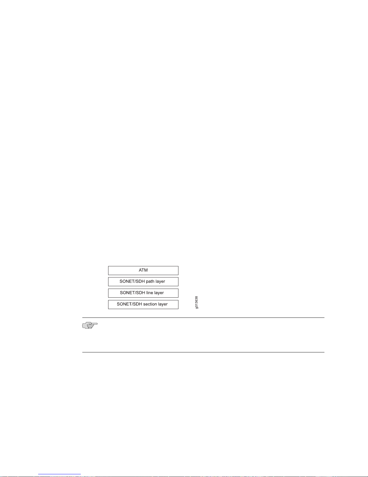
JUNOSe 11.0.x Physical Layer Configuration Guide
■ See ERX Module Guide, Appendix A, Module Protocol Support for information about
the protocols and applications that SONET/SDH modules support.
For detailed information about the modules that support SONET/SDH interfaces on
the E120 and E320 routers:
■ See E120 and E320 Module Guide, Table 1, Modules and IOAs for detailed module
specifications.
■ See E120 and E320 Module Guide, Appendix A, IOA Protocol Support for information
about the protocols and applications that SONET/SDH modules support.
OCx/STMx/DS3-ATM Line Modules
OCx/STMx/DS3-ATM line modules pair with OC3-4 I/O modules to deliver
unchannelized OC3/STM1 ATM operation through four line interfaces.
OCx/STMx/DS3-ATM line modules pair with OC12 I/O modules to deliver
unchannelized OC12/STM4 ATM operation through one line interface.
I/O modules that support single-mode (intermediate reach or long haul) or multimode
operation through SC full duplex connectors are available. I/O modules that support
SONET Automatic Protect Switching (APS) 1+1 redundancy and SDH Multiplex
Section Protection (MSP) are also available.
Figure 5 on page 78 shows the interface stack for OCx/STMx/DS3-ATM interfaces.
Figure 5: Interface Stack for OCx/STMx/DS3-ATM Interfaces
NOTE: For a detailed description of interface types and specifiers, see Interface Types
and Specifiers in JUNOSe Command Reference Guide. For information about interfaces,
see Planning Your Network in JUNOSe System Basics Configuration Guide.
OCx/STMx POS Line Modules
OCx/STMx POS line modules pair with OC3-4 I/O modules to deliver unchannelized
OC3/STM1 POS operation through four line interfaces.
OCx/STMx POS line modules pair with OC12 I/O modules to deliver unchannelized
OC12/STM4 POS operation through one line interface.
78 ■ Platform Considerations
 Loading...