

Page 1

JRR200 Route Reflector Quick Start
JRR200 Route Reflector Overview . . . . . . . . . . . . . . . . . . . . . . . . . . . . . . . . . . . . . . . . . . . . . . . . . . . . . . . . . . . . . . . . . . . . . . . . . . . . 1
Package Contents . . . . . . . . . . . . . . . . . . . . . . . . . . . . . . . . . . . . . . . . . . . . . . . . . . . . . . . . . . . . . . . . . . . . . . . . . . . . . . . . . . . . . 1
Register the Product . . . . . . . . . . . . . . . . . . . . . . . . . . . . . . . . . . . . . . . . . . . . . . . . . . . . . . . . . . . . . . . . . . . . . . . . . . . . . . . . . . . 2
JRR200 Route Reflector Chassis Overview . . . . . . . . . . . . . . . . . . . . . . . . . . . . . . . . . . . . . . . . . . . . . . . . . . . . . . . . . . . . . . . . . . . . 2
Mount the JRR200 Route Reflector on Four Posts of a Rack . . . . . . . . . . . . . . . . . . . . . . . . . . . . . . . . . . . . . . . . . . . . . . . . . . . . . . . 3
Connect the Grounding Cable . . . . . . . . . . . . . . . . . . . . . . . . . . . . . . . . . . . . . . . . . . . . . . . . . . . . . . . . . . . . . . . . . . . . . . . . . . . . . . . 4
Power on the JRR200 Route Reflector . . . . . . . . . . . . . . . . . . . . . . . . . . . . . . . . . . . . . . . . . . . . . . . . . . . . . . . . . . . . . . . . . . . . . . . . 5
Connect to the Console . . . . . . . . . . . . . . . . . . . . . . . . . . . . . . . . . . . . . . . . . . . . . . . . . . . . . . . . . . . . . . . . . . . . . . . . . . . . . . . . . . . . 7
Initial Configuration Using the CLI . . . . . . . . . . . . . . . . . . . . . . . . . . . . . . . . . . . . . . . . . . . . . . . . . . . . . . . . . . . . . . . . . . . . . . . . . . . . 8
Power Off the Device . . . . . . . . . . . . . . . . . . . . . . . . . . . . . . . . . . . . . . . . . . . . . . . . . . . . . . . . . . . . . . . . . . . . . . . . . . . . . . . . . . . . . . 9
Reset the Configuration . . . . . . . . . . . . . . . . . . . . . . . . . . . . . . . . . . . . . . . . . . . . . . . . . . . . . . . . . . . . . . . . . . . . . . . . . . . . . . . . . . . . 9
Safety Warnings Summary . . . . . . . . . . . . . . . . . . . . . . . . . . . . . . . . . . . . . . . . . . . . . . . . . . . . . . . . . . . . . . . . . . . . . . . . . . . . . . . . . 9
Reference . . . . . . . . . . . . . . . . . . . . . . . . . . . . . . . . . . . . . . . . . . . . . . . . . . . . . . . . . . . . . . . . . . . . . . . . . . . . . . . . . . . . . . . . . . . . . . . 9
JRR200 Route Reflector Overview
The Juniper Networks JRR200 Route Reflector is a 1U form factor appliance with a multicore x86 CPU and preinstalled vRR
software that can host one route-reflector instance. The JRR200 route reflector is suitable for large enterprises, data centers and
service providers for hosting vRR software to scale up to 30 million routing information base (RIB) entries.
The JRR200 route reflector comes with eight 1/ 10 Gigabit Ethernet SFP+ ports, 64 GB of DDR4 memory, and two 240-GB
solid-state drives (SSDs) in a RAID1 configuration. The JRR200 route reflector is available in both AC and DC models which
support Zero Touch Provisioning mode (ZTP) to ensure seamless insertion into the network and provide operational simplicity.
For more information about the JRR200 Route Reflector Hardware, see the JRR200 Route Reflector Hardware Guide available
at:
https://www.juniper.net/documentation/en_US/release-independent/junos/information-products/pathway-pages/jrr-series/jrr200/index.html
NOTE: The JRR200 route reflector shipment package contains a packing list. Check the parts in the shipment against
the items on the packing list. If anything is missing or damaged, contact your Juniper Networks customer service
representative.
Package Contents
The JRR200 route reflector is shipped with the following parts:
•
Four-post rack-mounting kit
•
Fourteen flat-head screws to secure the mounting brackets to the chassis
Page 2
g100080
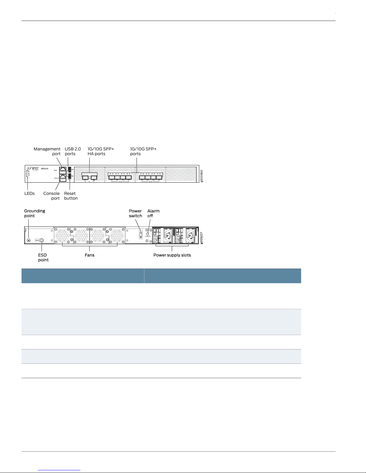
LEDs
Management
port
USB 2.0
ports
1G/10G SFP+
HA ports
1G/10G SFP+
ports
Console Reset
buttonport
JRR200 Route Reflector Quick Start
•
An AC power cord with plugs appropriate for your geographical location
•
RJ-45 cable and RJ-45 to DB-9 serial port adapter
Register the Product
Register product serial numbers on the Juniper Networks website and update the installation base data if there is any addition
or change to the installation base or if the installation base is moved. Juniper Networks will not be held accountable for not
meeting the hardware replacement service-level agreement for products that do not have registered serial numbers or accurate
installation base data.
Register your product at https://tools.juniper.net/svcreg/SRegSerialNum.jsp.
Update your installation base at https://www.juniper.net/customers/csc/management/updateinstallbase.jsp.
JRR200 Route Reflector Chassis Overview
Dimensions (H x W x D)
Chassis weight
ValueSpecification
1.75 in. x 17.48 in. x 25 in.
(4.45 cm x 44.40 cm x 63.50 cm)
29 lb (13.16 kg) with two AC power supplies
28.8 lb (13.06 kg) with two DC power supplies
200 WAverage power consumption
1500 BTU/hourMaximum thermal output
5% to 90%, non-condensingRelative humidity
Copyright © 2018, Juniper Networks, Inc.2
Page 3
g100081
JRR200 Route Reflector Quick Start
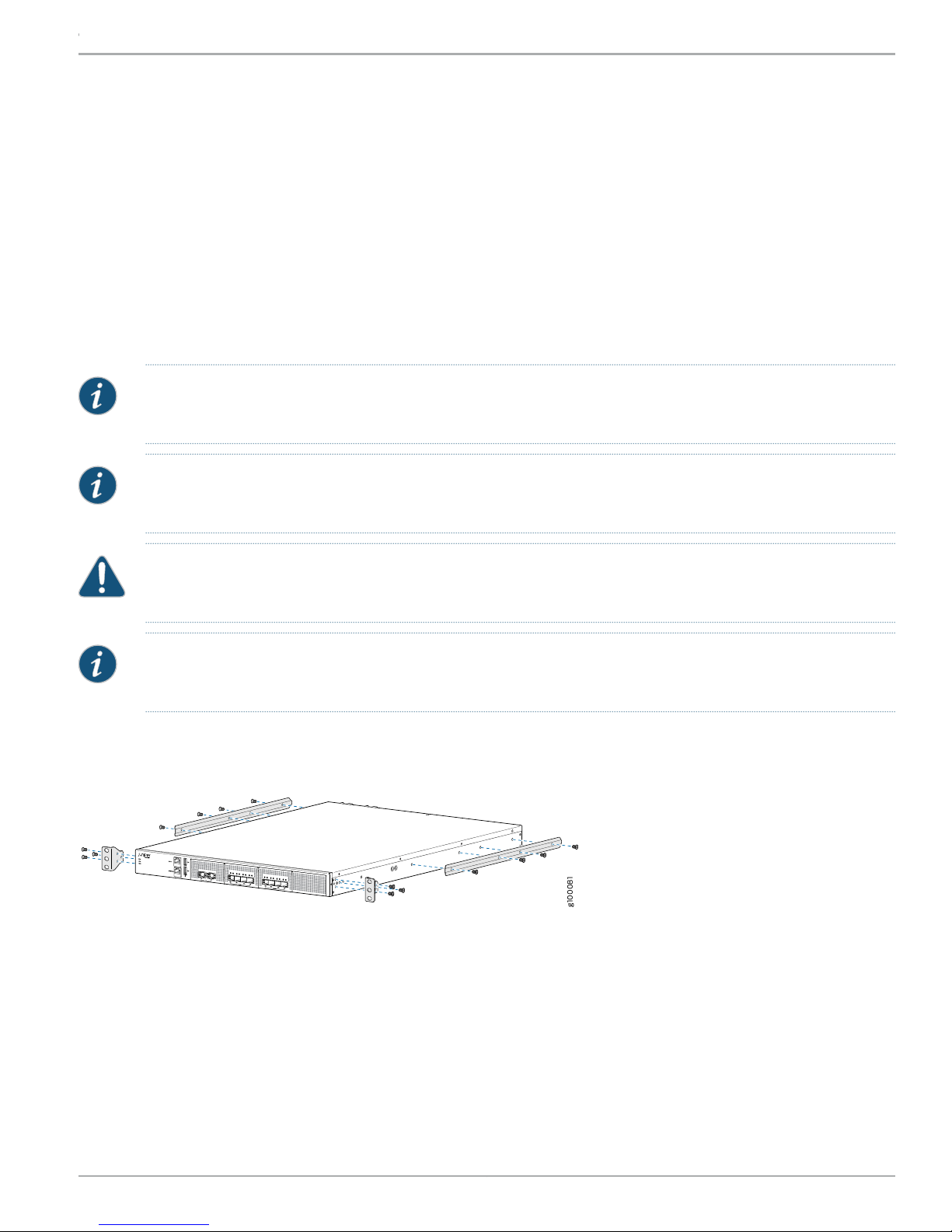
Mount the JRR200 Route Reflector on Four Posts of a Rack
You can mount a JRR200 route reflector in a 19-inch four-post rack configuration. An AC device weighs approximately 29 lb
(13.16 kg) and a DC device weighs approximately 28.8 lb (13.06 kg).
You will need the items listed below to mount the JRR200 route reflector onto the rack:
•
Electrostatic discharge (ESD) grounding strap
•
Screws to secure the mounting brackets to the chassis
•
Rack-mounting screws to secure the chassis to the four rack posts—not provided
•
Phillips (+) screwdriver, number 2
•
Two persons are required for mounting the JRR200 route reflector.
NOTE: Ensure that the rack is in its permanent location, allowing adequate clearance for airflow and maintenance,
and secured to the building structure.
NOTE: If you are mounting multiple units in the rack, mount the heaviest unit at the bottom and mount the others
from bottom to top in order of decreasing weight.
CAUTION: Wrap and fasten one end of the ESD grounding strap around your wrist and connect the other end to a
site ESD point.
NOTE: Ensure that the rear of the JRR200 route reflector is supported throughout the process of mounting the
JRR200 route reflector into the rack.
To mount the JRR200 route reflector on a rack:
1. Attach the front-mounting brackets and the side mounting rails to the chassis by using the flat-head screws.
3Copyright © 2018, Juniper Networks, Inc.
Page 4

g100082
g100083
JRR200 Route Reflector Quick Start
2. Have one person grasp both sides of the JRR200 route reflector, lift it, and position it in the rack so that the front mounting
bracketholesalign with the threaded holes in the rack rail and the second person secure the front of the JRR200 route reflector
to the rack by using rack-mounting screws (and cage nuts and washers if your rack requires them).
3. Continue to support the JRR200 route reflector, and have the second person slide the rear mounting blades into the channels
of the side mounting rails and secure the blades to the rack. Use rack-mounting screws (and cage nuts and washers if your
rack requires them) to attach the sliding blades to the rack.
Connect the Grounding Cable
1. Attach an electrostatic discharge (ESD) grounding strap to your bare wrist, and connect the strap to an approved site ESD
grounding point. See the instructions for your site.
2. Connect one end of the grounding cable to a proper earth ground, such as the rack in which the JRR200 route reflector is
mounted.
Copyright © 2018, Juniper Networks, Inc.4
Page 5

3. Place the grounding cable lug over the grounding point on the rear of the chassis.
NOTE: The JRR200 route reflector should be permanently connected to ground during normal operation. A
licensed electrician must attach a cable lug to the grounding cable. A cable with an incorrectly attached lug can
damage the JRR200 route reflector.
JRR200 Route Reflector Quick Start
4. Secure the grounding cable lug to the grounding point with the screw.
5. Dress the grounding cable and ensure that it does not touch or block access to other device components and that it does not
drape where people could trip over it.
Power on the JRR200 Route Reflector
NOTE: Check that the AC or DC power supplies are fully inserted into the chassis.
If you are using the AC model, perform the following steps:
1. Set the power switch on the JRR200 route reflector to the off (O) position.
2. Insert the coupler end of the power cord into the AC power cord inlet on the AC power supply faceplate. Push the power cord
retainer onto the power cord.
NOTE: An AC-powered device gets additional grounding when you connect the power supply in the device to a
grounded AC power outlet by using the power cord.
3. Insert the power cord plug into an AC power source outlet.
5Copyright © 2018, Juniper Networks, Inc.
Page 6

JRR200 Route Reflector Quick Start
4. Repeat steps 2 and 3 for the second AC power supply.
•
5. If the AC power source outlet has a power switch, set it to on (|) position. Set the power switch on the JRR200 route reflector
to the on (|) position and it will power on.
•
If there is no power switch on the AC power source outlet, set the power switch on the JRR200 route reflector to the on (|)
position and it will power on.
6. Verify that the AC and DC LEDs on each power supply are lit green.
If you are using the DC model, perform the following steps:
WARNING: Before performing the following procedure, ensure that there is no power in the DC circuit. To ensure that
all power is cut off, locate the circuit breaker on the panel board that services the DC circuit, switch the circuit breaker
to the off (0) position, and tape the switch handle of the circuit breaker in the off position.
1. Ensure that the voltage across the DC power source cable leads is 0 V and that the cable leads do not become active while
you are connecting DC power.
2. Verify that the DC power cablesare correctlylabeled beforeconnectingthemtothepower supply.Inatypicalpower distribution
scheme where the return is connected to chassis ground at the battery plant, you can use a multi-meter to verify the resistance
of the – 48 V and RTN DC cables to chassis ground:
•
The cable with very high resistance (indicating an open circuit) to chassis ground will be connected to the V - (input) DC
power input terminal.
•
The cable with very low resistance (indicating a closed circuit) to chassis ground will be connected to the V + (return) DC
power input terminal.
3. Remove the protective cover from the terminal studs on the faceplate. Save this cover for future use.
4. Remove the screws on the terminals by using a number 2 Phillips (+) screwdriver.
5. Secure each positive (+) DC source power cable lug to a RTN (return) terminal. Secure each negative (–) DC source power
cable lug to a -48 V (input) terminal.
6. Tighten the screws on the power supply terminals until snug using the screwdriver. Do not overtighten.
7. Replace the protective cover over the terminal studs on the faceplate.
8. Switch the circuit breaker to the ON (|) position.
9. Verify that the IN and OUT LEDs on the power supply are lit green and are on steadily.
Copyright © 2018, Juniper Networks, Inc.6
Page 7

g100085
Power
Status
SSD
g100086
Console port
RJ-45 cable Serial port
JRR200 Route Reflector Quick Start
NOTE: Wait until the Status LED on the front panel of the JRR200 route reflector is solid green before proceeding
to the next step.
Connect to the Console
To configure the JRR200 route reflector, you must connect a management device to the CONSOLE port located on the front
panel of the JRR200 route reflector, using the provided RJ-45-to-DB-9 adapter and the RJ45 cable.
1. Attach an electrostatic discharge (ESD) grounding strap to your bare wrist, and connect the strap to the ESD point on the
chassis.
2. Plug one end of the RJ-45 cable into the CONSOLE port of the JRR200 route reflector and the other end into the DB-9 serial
port adapter.
3. Connect the DB-9 serial port adapter end of the RJ-45 cable to the serial port of your management device. Use the following
values to configure the serial port:
•
Baud rate—9600
•
Parity—N
•
Data bits—8
•
Stop bits—1
•
Flow control—None
7Copyright © 2018, Juniper Networks, Inc.
Page 8

JRR200 Route Reflector Quick Start
Initial Configuration Using the CLI
Access the CLI to perform the initial configuration.
1. Log in to the device as root. When the device is powered on with the factory-default configuration, you do not need to enter
a password.
2. At the (%) prompt, type cli to start the CLI and press Enter. The prompt changes to an angle bracket (>) when you enter the
CLI operational mode.
root% cli
root>
3. At the (>) prompt, type configure and press Enter. The prompt changes from > to # when you enter configuration mode.
root>configure
Entering configuration mode
[edit]
root#
4. Set the root authentication password by entering a cleartext password, an encrypted password, or an SSH public key string
(DSA or RSA).
root# set system root-authentication plain-text- password
New password: password
Retype new password: password
5. Configure the route for the management interface (optional, required only if you do not connect the MGMT port directly to the
management device).
root# set routing-options static route destination prefix next-hop gateway
6. Commit the configuration changes.
root# commit
7. Connect the MGMT port on the device to the Ethernet port on the management device using an RJ-45 cable.
8. The JRR200 route reflectorMGMTportis internallymappedto the em0 interface in Junos. By default, the managementnetwork
interface (em0) is configured with DHCP enabled. If there is a DHCP server on the management network, then the JRR200
management networkinterface is automaticallyassignedanIP address. If there is no DHCP server on the management network
then you need to configure the management network interface IP address by performing the following steps:
a. Delete the default management interface configuration.
root# delete interfaces em0
b. Configure a new IP address for the management interface.
root# set interfaces em0 unit 0 family inet address address/prefix-length
c. Commit the configuration changes.
root# commit
d. Configure an IP address for the management device. Ensure that the IP address is on the same subnetwork as the
management interface (em0).
9. When you have finished configuring the device, exit configuration mode:
Copyright © 2018, Juniper Networks, Inc.8
Page 9

JRR200 Route Reflector Quick Start
[edit]
root# exit
Power Off the Device
To power off the device, press the power switch on the rear of the device. After powering off the device, wait at least 60 seconds
before turning it back on.
Reset the Configuration
Pressing and holding the RESET button—which is on the front panel of the chassis—for 5 seconds or more deletes all configurations
(backup configurations and rescue configuration) on the device, and loads and commits the factory configuration.
Safety Warnings Summary
This is a summary of safety warnings.
For a complete list of warnings, including translations, see the JRR200 Route Reflector documentation at:
https://www.juniper.net/documentation/en_US/release-independent/junos/information-products/pathway-pages/jrr-series/product/
WARNING: Failure to observe the following safety warnings can result in personal injury or death:
•
Permit only trained and qualified personnel to install or replace device components.
•
Perform only the procedures described in this Quick Start Guide and the JRR200 route reflector documentation.
Other services must be performed only by authorized service personnel.
•
Before installing the JRR200 route reflector, read the planning instructions in the JRR200 route reflector
documentation to make sure that the site meets power, environmental, and clearance requirements for the device.
•
Before connecting the JRR200 route reflector to a power source, read the installation instructions in the JRR200
route reflector documentation.
•
The JRR200 route reflector weighs approximately 29 lb (13.16 kg). Manually installing the device in a rack requires
two persons; one to lift the device and the second to install the mounting screws. To prevent injury while lifting,
keep your back straight and lift with your legs, not your back.
•
If the rack has stabilizing devices, install them in the rack before mounting or servicing the device in the rack.
•
Before installing or after removing an electrical component, always place it component-side up on an antistatic
mat placed on a flat, stable surface or in an antistatic bag.
•
Do not work on the device or connect or disconnect cables during electrical storms.
•
Before working on equipment that is connected to power lines, remove jewelry, including rings, necklaces, and
watches. Metal objects heat up when connected to power and ground and can cause serious burns or become
welded to the terminals.
Reference
•
Technical Support
https://www.juniper.net/support/requesting-support.html
•
JRR200 Route Reflector Hardware Guide
https://www.juniper.net/documentation/en_US/release-independent/junos/information-products/pathway-pages/jrr-series/jrr200/index.html
•
Supported Transceivers
https://apps.juniper.net/hct/product/#prd=JRR200
9Copyright © 2018, Juniper Networks, Inc.
Page 10

JRR200 Route Reflector Quick Start
Juniper Networks, the Juniper Networks logo, Juniper, and Junos are registered trademarks of Juniper Networks, Inc. and/or its affiliates in the United States
and other countries. All other trademarks may be property of their respective owners. Juniper Networks assumes no responsibility for any inaccuracies in this
document. Juniper Networks reserves the right to change, modify, transfer, or otherwise revise this publication without notice. Copyright © 2018 Juniper
Networks, Inc. All rights reserved. Part Number: 530-087833 Rev. 02, June 2018.
 Loading...