
Juniper Interfaces for Security Devices User Manual

Junos® OS

Interfaces User Guide for Security Devices

Published

2021-03-31

ii

Juniper Networks, Inc. 1133 nn v n Way Sunnyvale, California 94089 USA

408-745-2000 www.juniper.net

Juniper Networks, the Juniper Networks logo, Juniper, and Junos are registered trademarks of Juniper Networks, Inc. in the United States and other countries. All other trademarks, service marks, registered marks, or registered service marks are the property of their r s c v owners.

Juniper Networks assumes no responsibility for any inaccuracies in this document. Juniper Networks reserves the right

to change, modify, transfer, or otherwise revise this b c

n without n c

Junos® OS Interfaces User Guide for Security Devices


Copyright © 2021 Juniper Networks, Inc. All rights reserved.


The n rm

n in this document is current as of the date on the

page.

YEAR 2000 NOTICE

Juniper Networks hardware and s ftw r products are Year 2000 compliant. Junos OS has no known m r

m ns through the year 2038. However, the NTP c n is known to have some c y in the year 2036.

END USER LICENSE AGREEMENT

The Juniper Networks product that is the subject of this technical

c m n

n consists of (or is intended for use

with) Juniper Networks s ftw r

Use of such s

ftw r

is subject to the terms and c n

ns of the End User License

Agreement ("EULA") posted at

s s

r

n r n

s

r

. By downloading, installing or using such

s ftw r you agree to the terms and c n

ns of that EULA.


iii

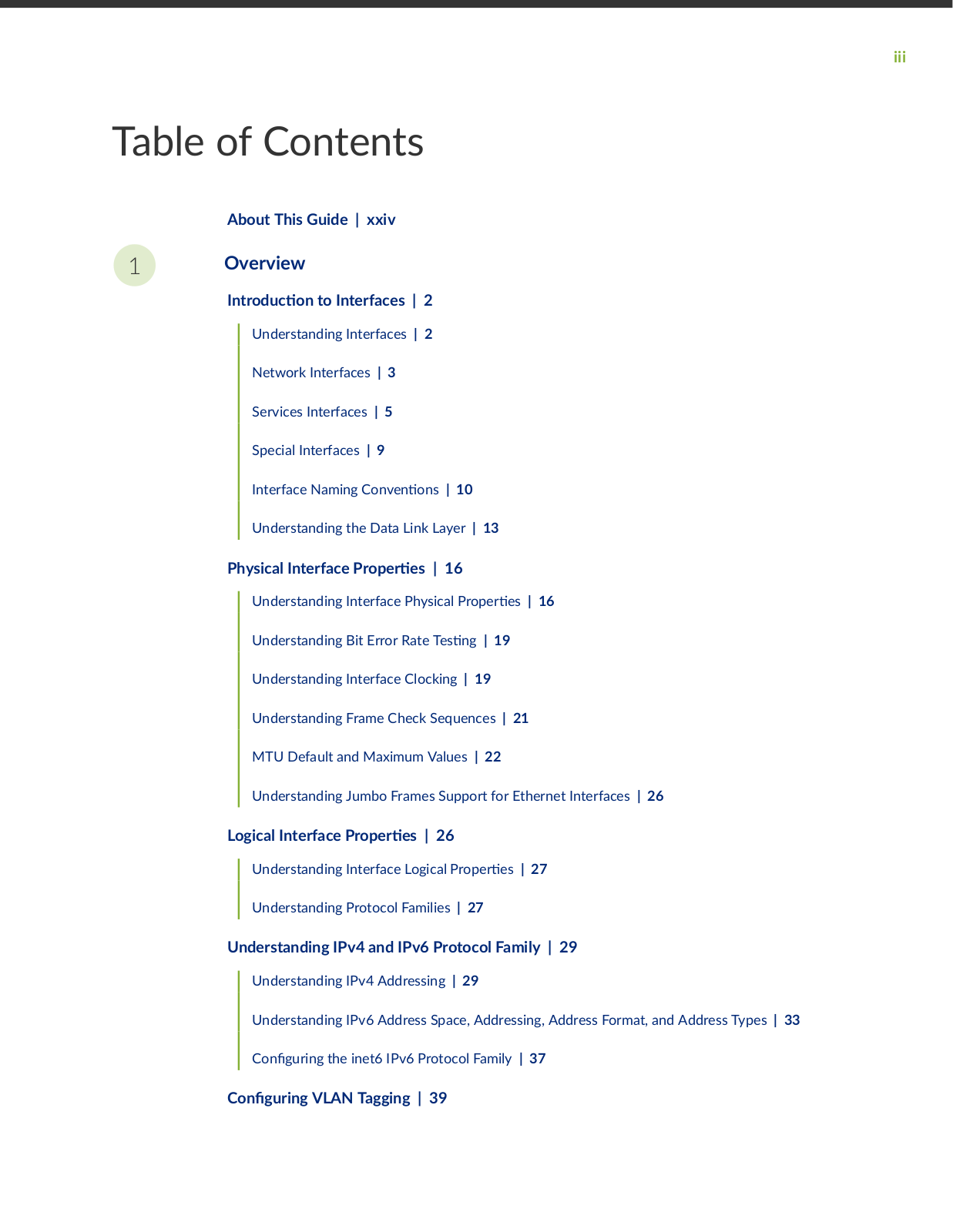
Table of Contents

About This Guide | xxiv

1Overview

n r

c n to Interfaces | 2


Understanding Interfaces |

2


Network Interfaces |

3


Services Interfaces |

5


Special Interfaces

|

9


Interface Naming C

nv n

ns | 10


Understanding the Data Link Layer | 13


Physical Interface

r


r

s | 16


Understanding Interface Physical

r

r

s | 16


Understanding Bit Error Rate

s

n

| 19


Understanding Interface Clocking | 19


Understanding Frame Check Sequences | 21


MTU Default and Maximum Values | 22


Understanding Jumbo Frames Support for Ethernet Interfaces | 26

Logical Interface r


r s

|

26


Understanding Interface Logical

r

r

s | 27


Understanding Protocol Families | 27


Understanding IPv4 and IPv6 Protocol Family | 29

Understanding IPv4 Addressing | 29

Understanding IPv6 Address Space, Addressing, Address Format, and Address Types | 33

C n r n the inet6 IPv6 Protocol Family | 37

C n r n VLAN Tagging | 39

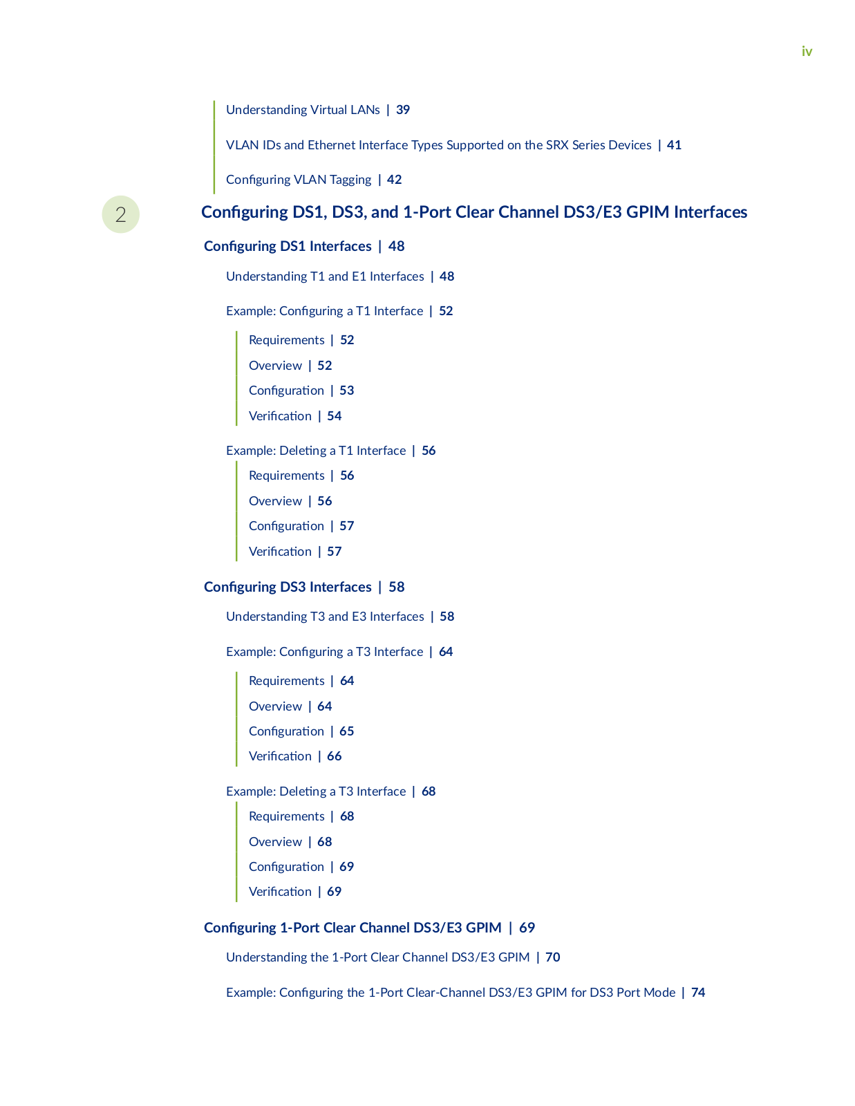
iv

Understanding Virtual LANs | 39

VLAN IDs and Ethernet Interface Types Supported on the SRX Series Devices | 41


C n


r n

VLAN Tagging | 42

2

C n

r n

DS1, DS3, and 1-Port Clear Channel DS3/E3 GPIM Interfaces


C n

r n

DS1 Interfaces | 48


Understanding T1 and E1 Interfaces | 48


Example: C

n

r n a T1 Interface | 52


Requirements | 52


Overview | 52


C n

r

n | 53


V r

c


n | 54


Example:


n a T1 Interface | 56


Requirements | 56


Overview | 56


C n

r

n | 57


V r

c


n | 57


C n r n DS3 Interfaces | 58

Understanding T3 and E3 Interfaces | 58

Example: C n r n a T3 Interface | 64


Requirements | 64


Overview | 64


C n

r

n | 65


V r

c

n | 66

Example:


n a T3 Interface | 68


Requirements | 68


Overview | 68


C n

r

n | 69


V r

c

n | 69


C n r n 1-Port Clear Channel DS3/E3 GPIM | 69

Understanding the 1-Port Clear Channel DS3/E3 GPIM | 70

Example: C n r n the 1-Port Clear-Channel DS3/E3 GPIM for DS3 Port Mode | 74

3

4

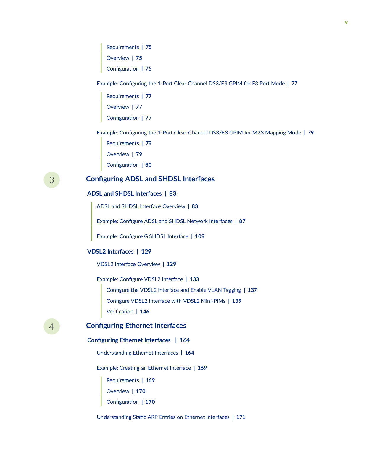
v

Requirements | 75

Overview | 75

C n r n | 75

Example: C n

r n the 1-Port Clear Channel DS3/E3 GPIM for E3 Port Mode | 77


Requirements | 77


Overview | 77


C n

r

n | 77

Example: C n

r n the 1-Port Clear-Channel DS3/E3 GPIM for M23 Mapping Mode | 79


Requirements | 79


Overview | 79


C n

r

n | 80

C n


r n

ADSL and SHDSL Interfaces


ADSL and SHDSL Interfaces | 83

ADSL and SHDSL Interface Overview | 83

Example: C n r ADSL and SHDSL Network Interfaces | 87

Example: C n r G.SHDSL Interface | 109

VDSL2 Interfaces | 129

VDSL2 Interface Overview | 129

Example: C

n

r VDSL2 Interface | 133


C n

r

the VDSL2 Interface and Enable VLAN Tagging | 137


C

n

r

VDSL2 Interface with VDSL2 Mini-PIMs | 139


V

r c


n | 146


C n r n Ethernet Interfaces

C n r n Ethernet Interfaces | 164

Understanding Ethernet Interfaces | 164

Example: Cr n an Ethernet Interface | 169

Requirements |

169

Overview | 170

C n r n |

170

Understanding S c ARP Entries on Ethernet Interfaces | 171

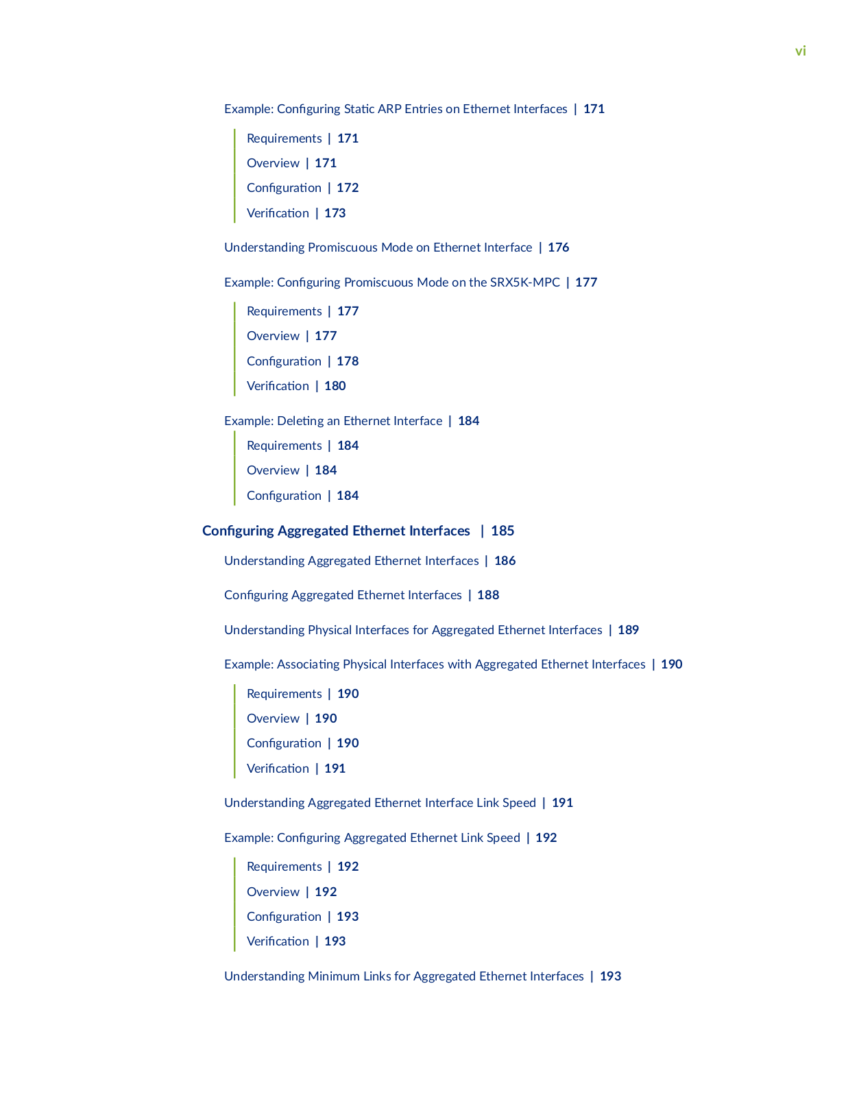
vi

Example: C n r n S c ARP Entries on Ethernet Interfaces | 171


Requirements | 171


Overview | 171


C n

r

n | 172


V r

c

n | 173

Understanding Promiscuous Mode on Ethernet Interface | 176

Example: C n

r n Promiscuous Mode on the SRX5K-MPC | 177


Requirements | 177


Overview | 177


C n

r

n | 178


V r

c

n | 180

Example:


n an Ethernet Interface | 184


Requirements | 184


Overview | 184


C n

r

n | 184


C n r n Aggregated Ethernet Interfaces | 185

Understanding Aggregated Ethernet Interfaces | 186

C n r n Aggregated Ethernet Interfaces | 188

Understanding Physical Interfaces for Aggregated Ethernet Interfaces | 189

Example: ss c n Physical Interfaces with Aggregated Ethernet Interfaces | 190


Requirements | 190


Overview | 190


C n

r

n | 190


V r c


n | 191

Understanding Aggregated Ethernet Interface Link Speed | 191

Example: C

n

r n Aggregated Ethernet Link Speed | 192

Requirements | 192

Overview | 192

C

n

r

n | 193

V

r

c

n | 193

Understanding Minimum Links for Aggregated Ethernet Interfaces | 193

vii

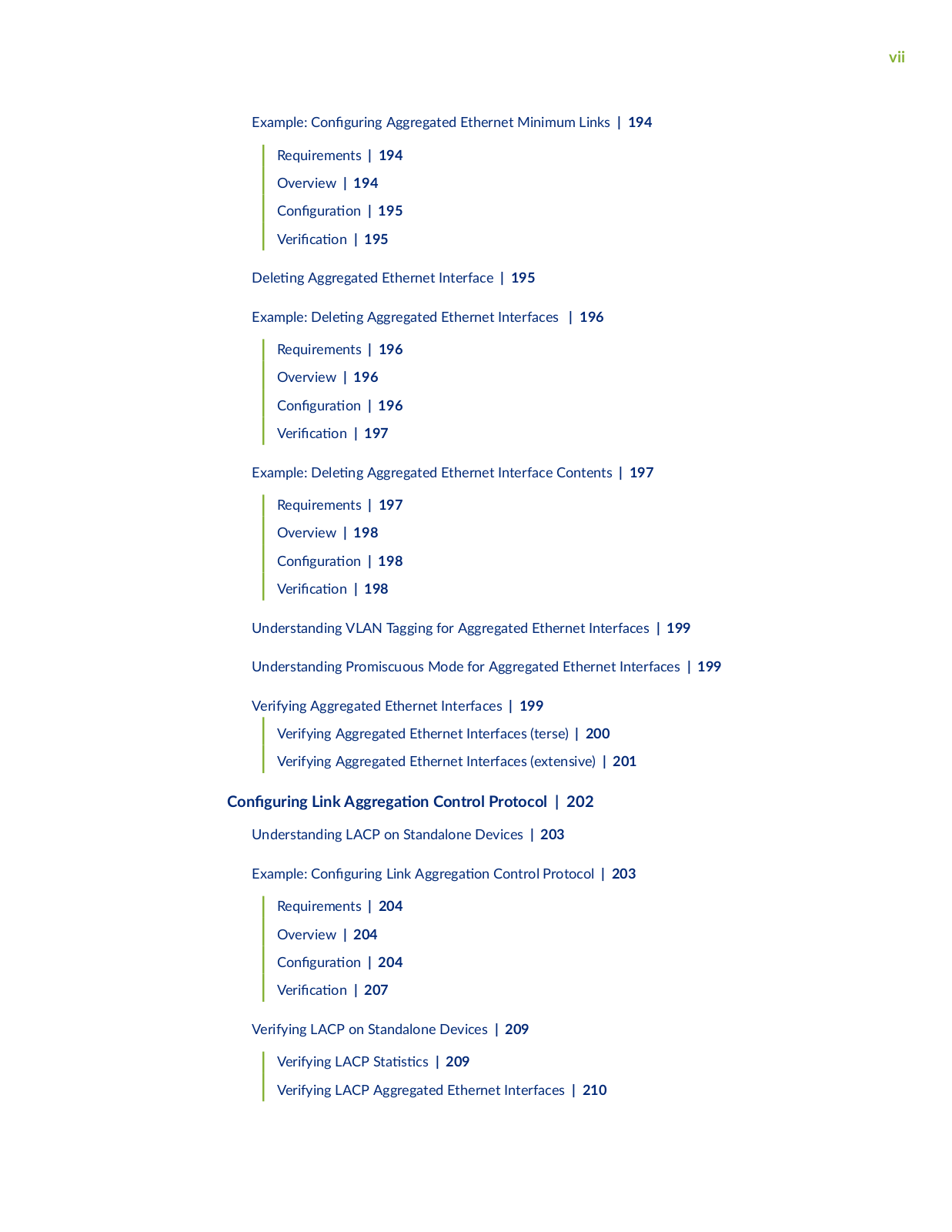
Example: C n r n Aggregated Ethernet Minimum Links | 194


Requirements | 194


Overview | 194


C n

r

n | 195


V r

c

n | 195


n

Aggregated Ethernet Interface | 195

Example:


n Aggregated Ethernet Interfaces | 196


Requirements | 196


Overview | 196


C n

r

n | 196


V r

c

n | 197

Example:


n Aggregated Ethernet Interface Contents | 197

Requirements | 197

Overview | 198

C

n

r

n | 198

V

r

c

n | 198

Understanding VLAN Tagging for Aggregated Ethernet Interfaces | 199

Understanding Promiscuous Mode for Aggregated Ethernet Interfaces | 199

Verifying Aggregated Ethernet Interfaces | 199

Verifying Aggregated Ethernet Interfaces (terse) | 200

Verifying Aggregated Ethernet Interfaces (extensive) | 201

C n

r n

Link

r


n Control Protocol | 202

Understanding LACP on Standalone Devices | 203

Example: C n


r n

Link

r

n Control Protocol | 203


Requirements | 204


Overview | 204


C n

r


n | 204


V r

c

n | 207


Verifying LACP on Standalone Devices | 209


Verifying LACP S

s

cs | 209


Verifying LACP Aggregated Ethernet Interfaces | 210


viii

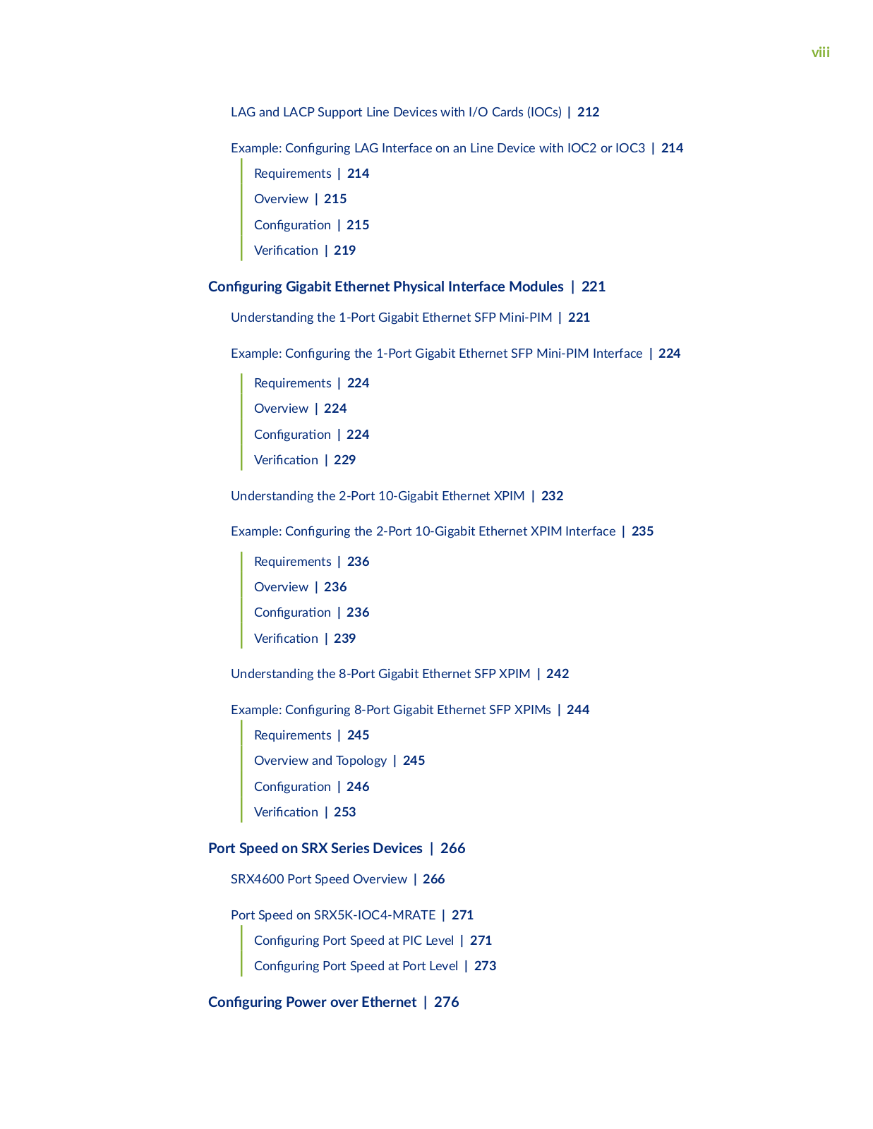
LAG and LACP Support Line Devices with I/O Cards (IOCs) | 212

Example: C n

r n LAG Interface on an Line Device with IOC2 or IOC3 | 214


Requirements | 214


Overview | 215


C

n

r

n | 215


V

r

c

n | 219


C n

r n

Gigabit Ethernet Physical Interface Modules | 221

Understanding the 1-Port Gigabit Ethernet SFP Mini-PIM | 221

Example: C n

r n the 1-Port Gigabit Ethernet SFP Mini-PIM Interface | 224


Requirements | 224


Overview | 224


C n

r

n | 224


V r

c

n | 229

Understanding the 2-Port 10-Gigabit Ethernet XPIM | 232

Example: C n

r n the 2-Port 10-Gigabit Ethernet XPIM Interface | 235


Requirements | 236


Overview | 236


C n

r

n | 236


V r

c

n | 239

Understanding the 8-Port Gigabit Ethernet SFP XPIM | 242

Example: C n

r n 8-Port Gigabit Ethernet SFP XPIMs | 244


Requirements | 245


Overview and Topology | 245


C n

r

n | 246


V r

c

n | 253


Port Speed on SRX Series Devices | 266

SRX4600 Port Speed Overview | 266

Port Speed on SRX5K-IOC4-MRATE | 271

C

n

r n

Port Speed at PIC Level | 271

C

n

r n

Port Speed at Port Level | 273

C n r n Power over Ethernet | 276

ix

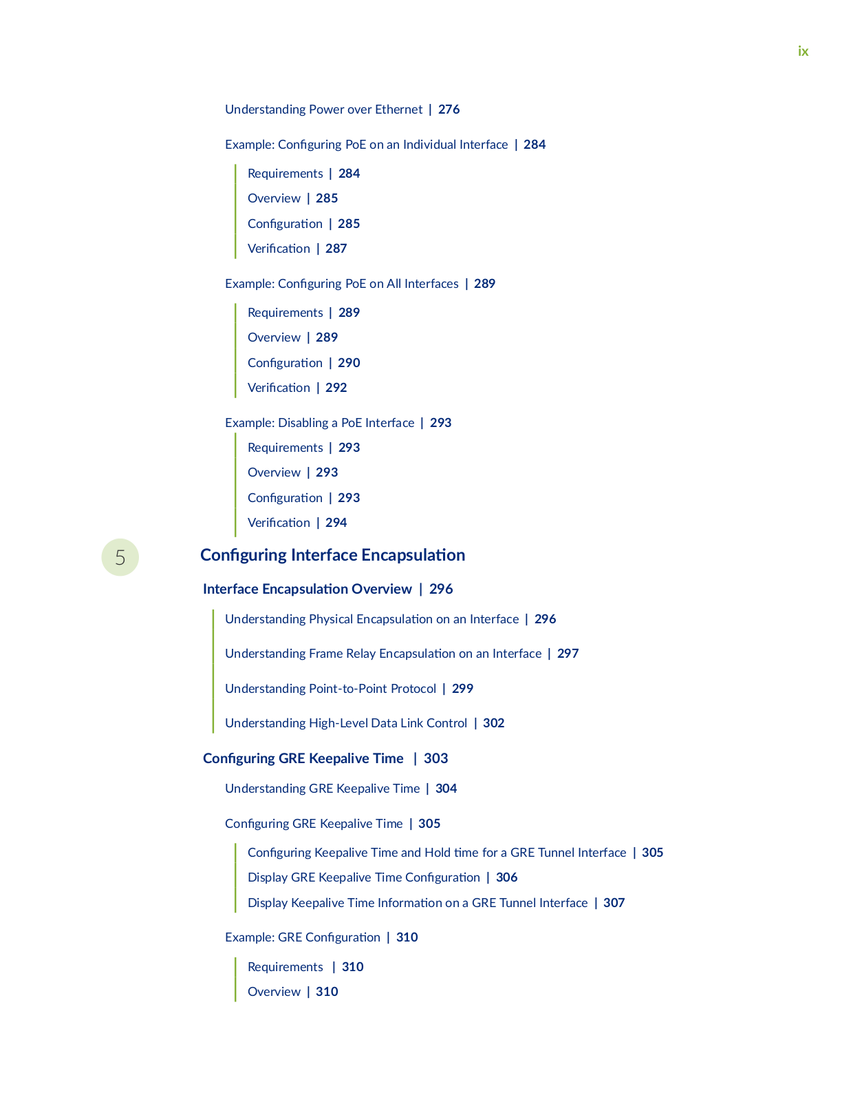
Understanding Power over Ethernet | 276

Example: C n

r n PoE on an Individual Interface | 284


Requirements | 284


Overview | 285


C n

r

n | 285


V r

c

n | 287

Example: C n

r n PoE on All Interfaces | 289


Requirements | 289


Overview | 289


C n

r

n | 290


V r

c

n | 292

Example: Disabling a PoE Interface | 293


Requirements | 293


Overview | 293


C n

r

n | 293


V r

c

n | 294


5

C n

r n

Interface

nc

s

n


Interface nc

s

n Overview | 296


Understanding Physical

nc

s


n on an Interface | 296


Understanding Frame Relay

nc

s

n on an Interface | 297


Understanding Point-to-Point Protocol | 299


Understanding High-Level Data Link Control | 302


C n r n GRE Keepalive Time | 303

Understanding GRE Keepalive Time | 304

C n

r n

GRE Keepalive Time | 305


C

n

r n Keepalive Time and Hold

m for a GRE Tunnel Interface | 305


Display GRE Keepalive Time C n

r

n | 306


Display Keepalive Time n rm

n on a GRE Tunnel Interface | 307

Example: GRE C n

r n | 310


Requirements

| 310


Overview | 310


x


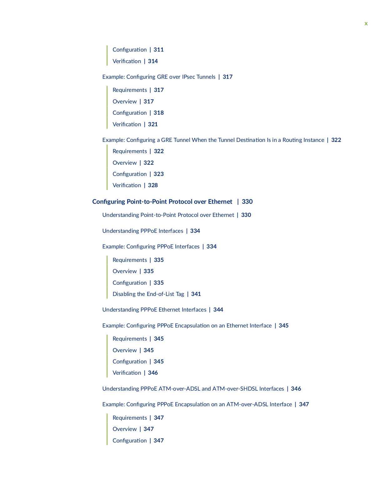
C n

r

n | 311


V r

c

n | 314

Example: C n

r n GRE over IPsec Tunnels | 317


Requirements | 317


Overview | 317


C n

r

n | 318


V r

c

n | 321


Example: C n

r n a GRE Tunnel When the Tunnel s n n Is in a R n Instance | 322


Requirements | 322


Overview | 322


C

n

r

n | 323


V

r

c

n | 328


C n r n Point-to-Point Protocol over Ethernet | 330

Understanding Point-to-Point Protocol over Ethernet | 330

Understanding PPPoE Interfaces | 334

Example: C n r n PPPoE Interfaces | 334

Requirements | 335

Overview | 335

C n r n | 335

Disabling the End-of-List Tag | 341

Understanding PPPoE Ethernet Interfaces | 344

Example: C

n

r n PPPoE

nc

s

n on an Ethernet Interface | 345


Requirements | 345


Overview | 345


C n

r

n | 345


V r c


n | 346


Understanding PPPoE ATM-over-ADSL and ATM-over-SHDSL Interfaces | 346

Example: C n

r n PPPoE

nc

s

n on an ATM-over-ADSL Interface | 347


Requirements | 347


Overview | 347


C n

r

n | 347


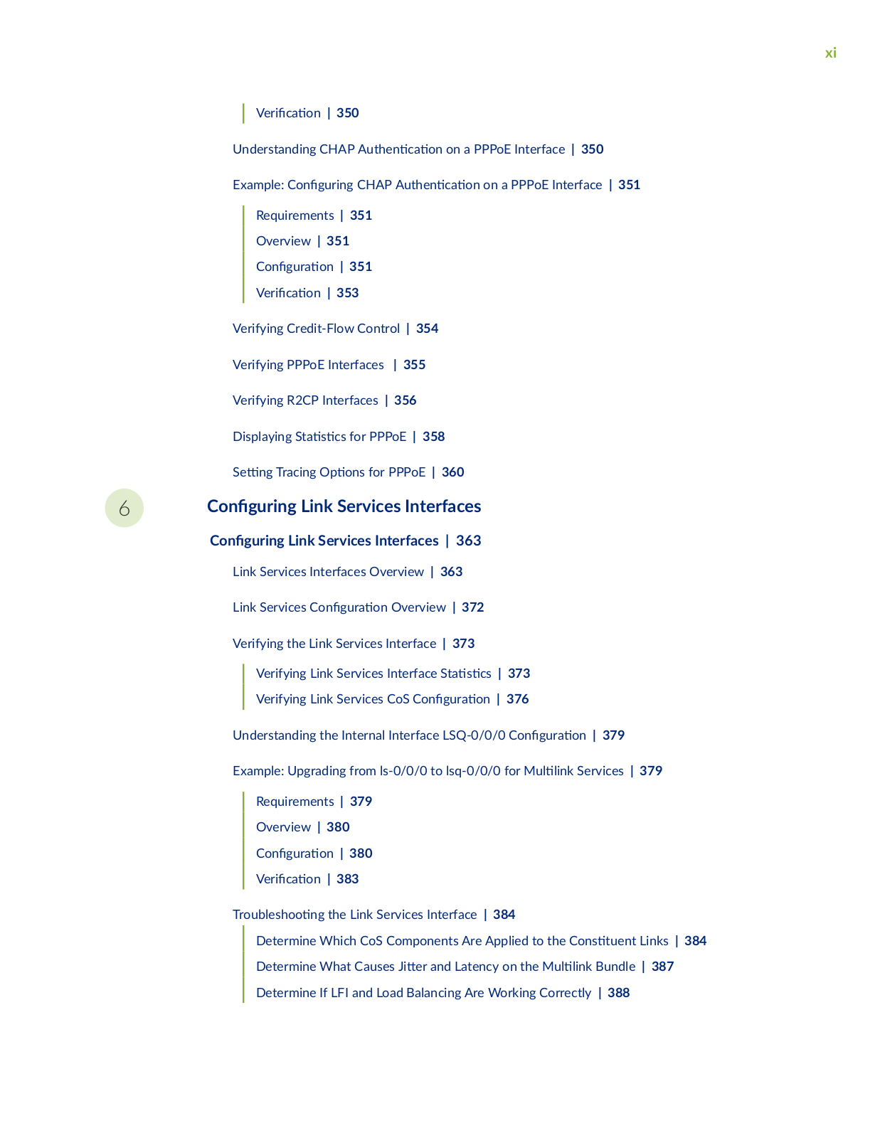
xi


V r

c

n | 350


Understanding CHAP

n c

n on a PPPoE Interface | 350

Example: C n

r n

CHAP

n c n on a PPPoE Interface | 351


Requirements | 351


Overview | 351


C n

r

n | 351


V r

c

n | 353


Verifying Credit-Flow Control | 354

Verifying PPPoE Interfaces | 355

Verifying R2CP Interfaces | 356

Displaying S s cs for PPPoE | 358


S

n Tracing

ns for PPPoE | 360


6

C

n

r n Link Services Interfaces


C

n

r n

Link Services Interfaces | 363


Link Services Interfaces Overview | 363


Link Services C

n r n Overview | 372


Verifying the Link Services Interface | 373


Verifying Link Services Interface S

s

cs | 373


Verifying Link Services CoS C n

r

n | 376


Understanding the Internal Interface LSQ-0/0/0 C n

r

n | 379


Example: Upgrading from ls-0/0/0 to lsq-0/0/0 for M

n

Services | 379


Requirements | 379


Overview | 380


C n

r

n | 380


V r

c n | 383


rb s n the Link Services Interface | 384

Determine Which CoS Components Are Applied to the C ns

n Links | 384

Determine What Causes

r and Latency on the M

n Bundle | 387

Determine If LFI and Load Balancing Are Working Correctly | 388

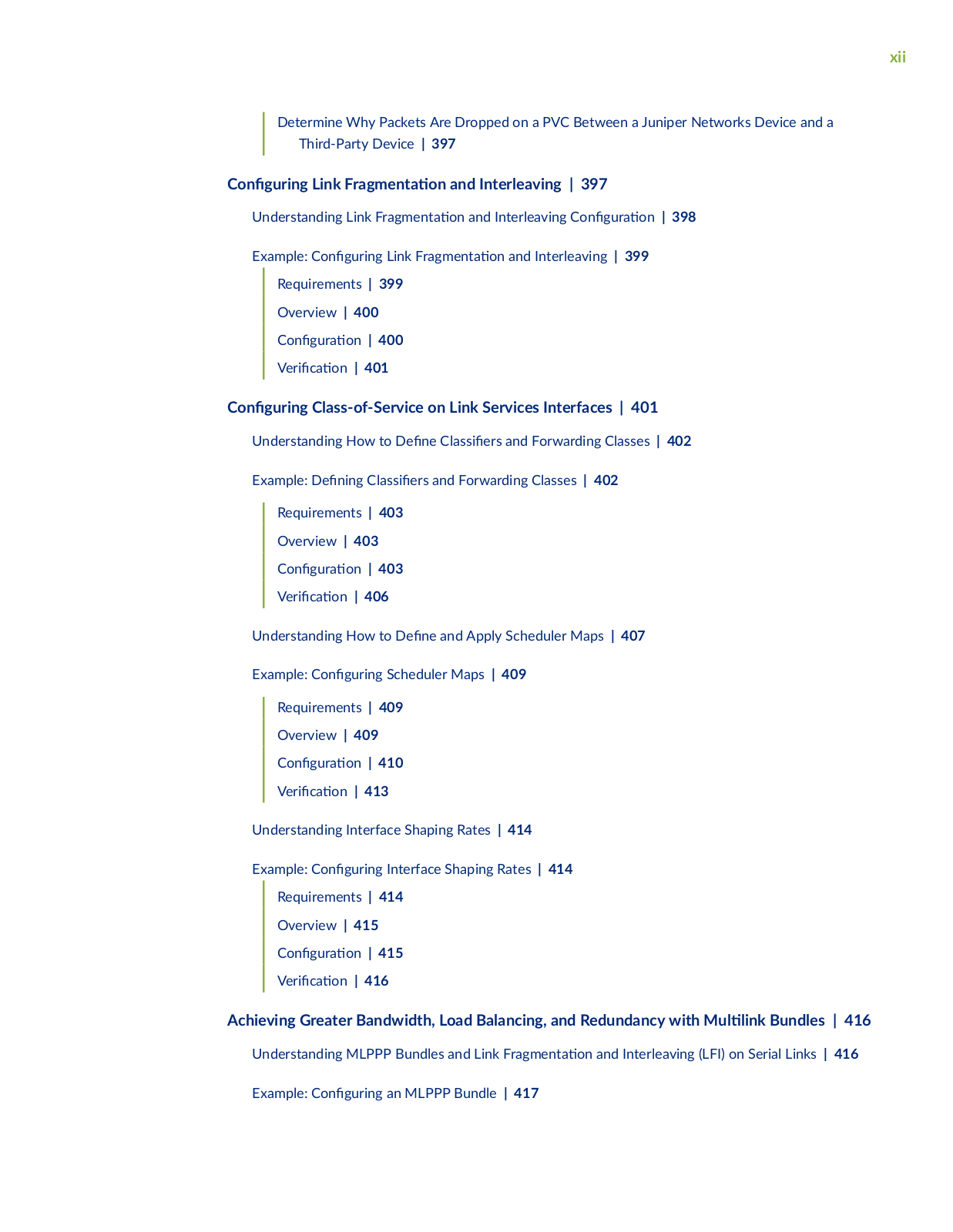
xii

Determine Why Packets Are Dropped on a PVC Between a Juniper Networks Device and a Third-Party Device | 397

C

n

r n

Link Fr

m n

n and Interleaving | 397


Understanding Link Fr

m n

n and Interleaving C n r n | 398


Example: C n


r n Link Fr

m n

n and Interleaving | 399


Requirements | 399


Overview | 400


C n

r

n | 400


V r

c

n | 401


C

n

r n

Class-of-Service on Link Services Interfaces | 401


Understanding How to

n

C ss

rs and Forwarding Classes | 402


Example:


n n

C ss

rs and Forwarding Classes | 402


Requirements | 403


Overview | 403


C n

r

n | 403


V r

c

n | 406


Understanding How to

n

and Apply Scheduler Maps | 407


Example: C n


r n Scheduler Maps | 409


Requirements | 409


Overview | 409


C n

r

n | 410


V r

c

n | 413


Understanding Interface Shaping Rates | 414


Example: C n


r n Interface Shaping Rates | 414


Requirements | 414


Overview | 415


C n

r

n | 415


V r

c

n | 416


Achieving Greater Bandwidth, Load Balancing, and Redundancy with M

n Bundles | 416

Understanding MLPPP Bundles and Link Fr m n

n and Interleaving (LFI) on Serial Links | 416

Example: C n r n an MLPPP Bundle | 417


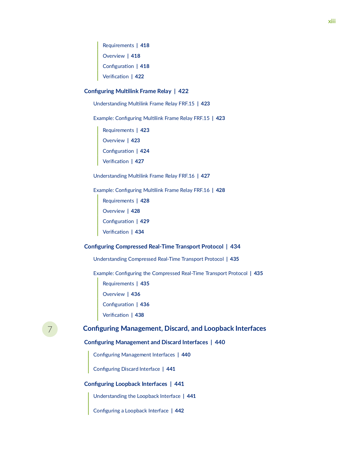
xiii

Requirements | 418

Overview | 418

C

n

r

n | 418

V

r

c

n | 422


C n

r n

M

n

Frame Relay | 422


Understanding M

n

Frame Relay FRF.15 | 423


Example: C n

r n

M

n Frame Relay FRF.15 | 423


Requirements | 423


Overview | 423


C n


r

n | 424


V r

c


n | 427


Understanding M

n

Frame Relay FRF.16 | 427


Example: C n

r n

M

n Frame Relay FRF.16 | 428


Requirements | 428


Overview | 428


C n


r

n | 429


V r

c


n | 434


C

n

r n

Compressed Real-Time Transport Protocol | 434


Understanding Compressed Real-Time Transport Protocol | 435


Example: C

n

r n

the Compressed Real-Time Transport Protocol | 435


Requirements | 435


Overview | 436


C n


r

n | 436


V r

c


n | 438


7

C

n

r n

Management, Discard, and Loopback Interfaces


C

n

r n

Management and Discard Interfaces | 440


C n

r n

Management Interfaces | 440

C n r n Discard Interface | 441

C n r n Loopback Interfaces | 441

Understanding the Loopback Interface | 441

C n r n a Loopback Interface | 442

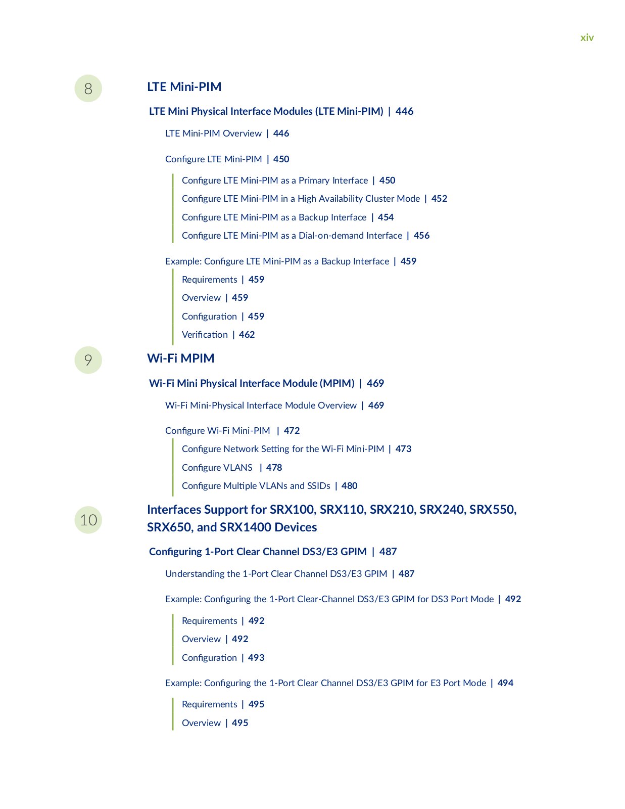
xiv

8

9

LTE Mini-PIM

LTE Mini Physical Interface Modules (LTE Mini-PIM) | 446

LTE Mini-PIM Overview | 446

C n

r

LTE Mini-PIM | 450


C

n


r

LTE Mini-PIM as a Primary Interface | 450


C

n


r

LTE Mini-PIM in a High Availability Cluster Mode | 452


C

n


r

LTE Mini-PIM as a Backup Interface | 454


C

n


r

LTE Mini-PIM as a Dial-on-demand Interface | 456

Example: C

n

r LTE Mini-PIM as a Backup Interface | 459


Requirements | 459


Overview | 459


C n


r

n | 459


V r

c


n | 462


Wi-Fi MPIM

Wi-Fi Mini Physical Interface Module (MPIM) | 469

Wi-Fi Mini-Physical Interface Module Overview | 469

C n r

Wi-Fi Mini-PIM

| 472


C n

r

Network S

n for the Wi-Fi Mini-PIM | 473


C n

r

VLANS

| 478


C n

r

M

VLANs and SSIDs | 480


10

Interfaces Support for SRX100, SRX110, SRX210, SRX240, SRX550,

SRX650, and SRX1400 Devices


C n r n 1-Port Clear Channel DS3/E3 GPIM | 487

Understanding the 1-Port Clear Channel DS3/E3 GPIM | 487

Example: C n

r n

the 1-Port Clear-Channel DS3/E3 GPIM for DS3 Port Mode | 492


Requirements | 492


Overview | 492


C n r

n | 493

Example: C n

r n

the 1-Port Clear Channel DS3/E3 GPIM for E3 Port Mode | 494

Requirements | 495

Overview | 495

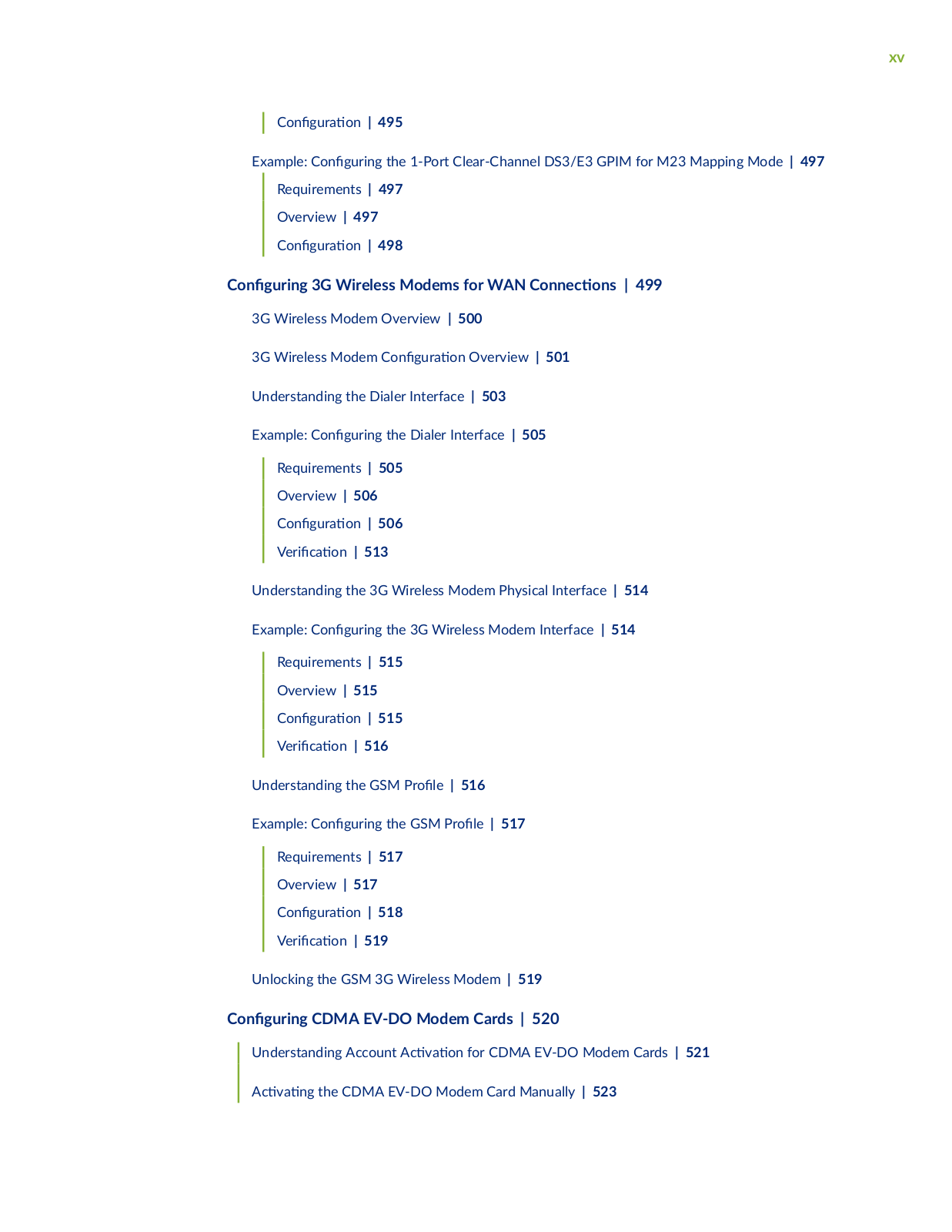
xv


C n

r

n | 495

Example: C n

r n the 1-Port Clear-Channel DS3/E3 GPIM for M23 Mapping Mode | 497


Requirements | 497


Overview | 497


C n

r

n | 498

C n r n

3G Wireless Modems for WAN C nn c ns | 499

3G Wireless Modem Overview | 500

3G Wireless Modem C n r n Overview | 501

Understanding the Dialer Interface | 503

Example: C n r n the Dialer Interface | 505

Requirements | 505

Overview | 506

C

n

r

n | 506

V

r

c

n | 513

Understanding the 3G Wireless Modem Physical Interface | 514

Example: C n r n the 3G Wireless Modem Interface | 514


Requirements | 515


Overview | 515


C n

r

n | 515


V r

c

n | 516


Understanding the GSM

r

| 516


Example: C n

r n the GSM

r

| 517


Requirements | 517


Overview | 517


C n

r

n | 518


V r

c

n | 519


Unlocking the GSM 3G Wireless Modem | 519

C n r n

CDMA EV-DO Modem Cards | 520


Understanding Account

c v

n for CDMA EV-DO Modem Cards | 521


c v n

the CDMA EV-DO Modem Card Manually | 523


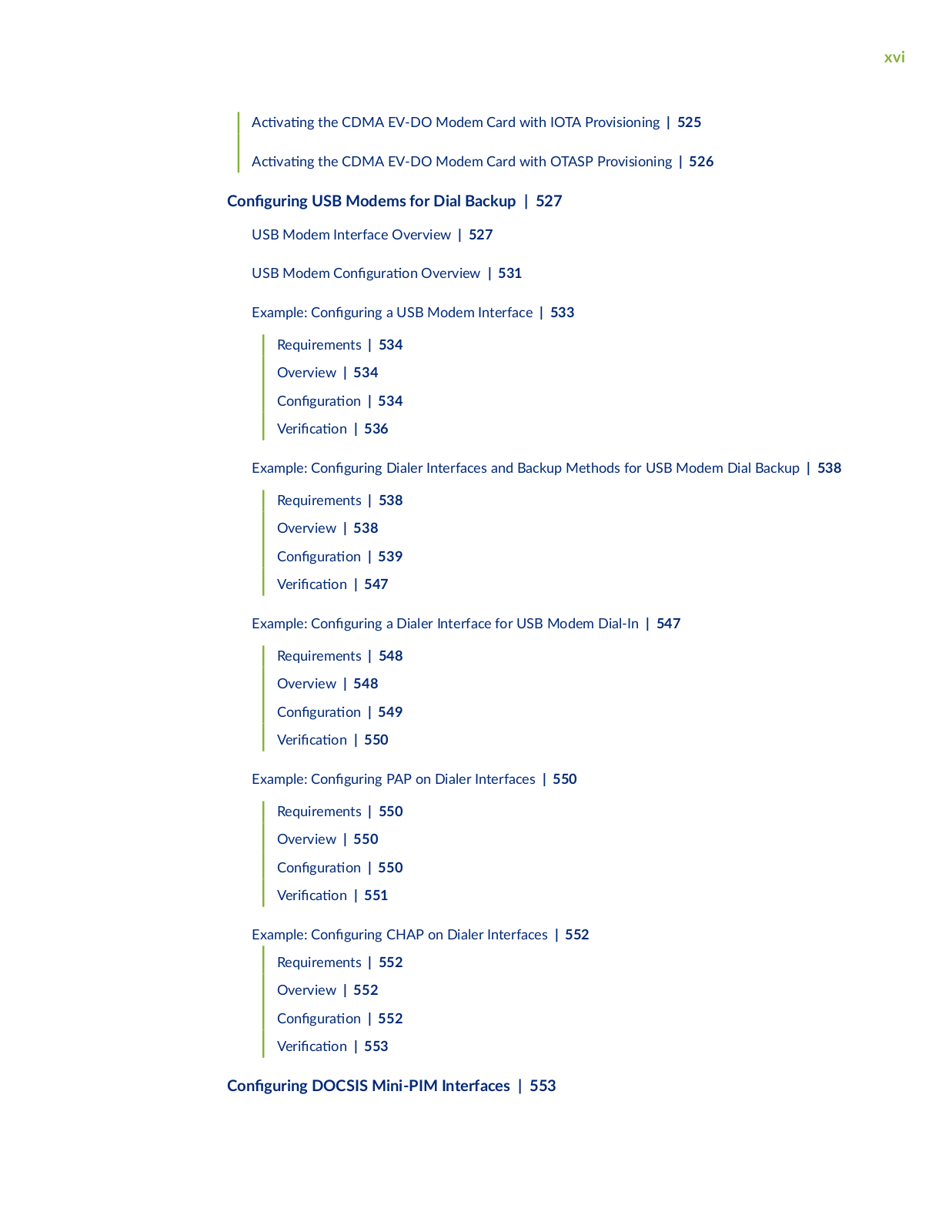
xvi

c

v

n

the CDMA EV-DO Modem Card with IOTA Provisioning | 525

c

v

n

the CDMA EV-DO Modem Card with OTASP Provisioning | 526

C n r n USB Modems for Dial Backup | 527

USB Modem Interface Overview | 527

USB Modem C n

r n Overview | 531

Example: C n

r n

a USB Modem Interface | 533


Requirements | 534


Overview | 534


C n

r

n | 534


V r

c

n | 536

Example: C n

r n

Dialer Interfaces and Backup Methods for USB Modem Dial Backup | 538


Requirements | 538


Overview | 538


C n

r

n | 539


V r

c

n | 547

Example: C n

r n

a Dialer Interface for USB Modem Dial-In | 547


Requirements | 548


Overview | 548


C n

r

n | 549


V r

c

n | 550

Example: C n

r n

PAP on Dialer Interfaces | 550


Requirements | 550


Overview | 550


C n

r

n | 550


V r

c

n | 551

Example: C n

r n

CHAP on Dialer Interfaces | 552


Requirements | 552


Overview | 552


C n

r

n | 552


V r

c

n | 553


C n r n DOCSIS Mini-PIM Interfaces | 553

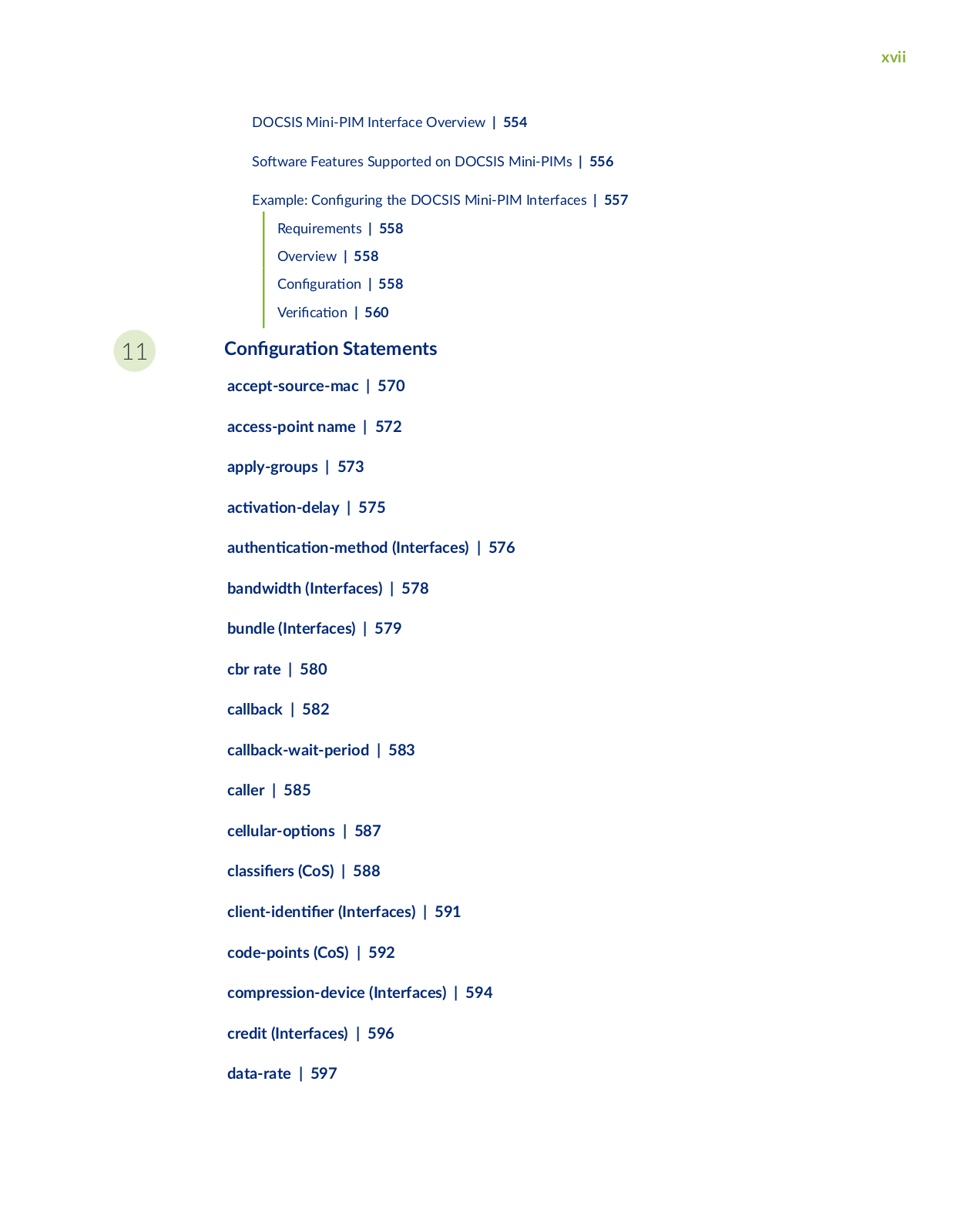
xvii

DOCSIS Mini-PIM Interface Overview | 554

S ftw r Features Supported on DOCSIS Mini-PIMs | 556

Example: C

n

r n the DOCSIS Mini-PIM Interfaces | 557


Requirements | 558


Overview | 558


C

n

r

n | 558


V

r c


n | 560


11

C n

r

n Statements


accept-source-mac | 570


access-point name | 572


apply-groups | 573


c

v

n

y | 575


n

c

n m

(Interfaces) | 576


bandwidth (Interfaces) | 578


bundle (Interfaces) | 579


cbr rate | 580


callback | 582


callback-wait-period | 583


caller |

585


c

r


ns | 587


c

ss

rs (CoS) | 588


c

n

n

r (Interfaces) | 591

code-points (CoS) | 592

compression-device (Interfaces) | 594 credit (Interfaces) | 596

data-rate | 597

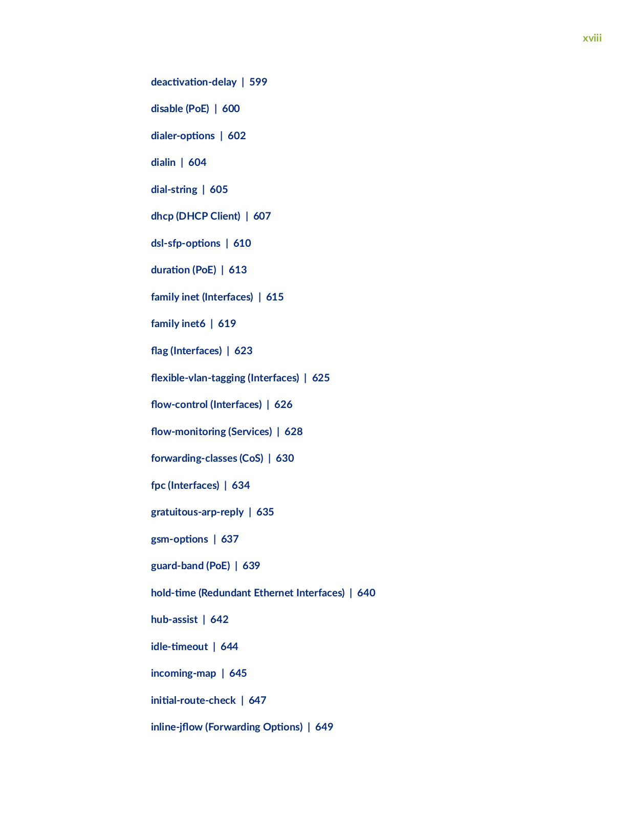
xviii

c

v

n

y | 599

disable (PoE) | 600

r


ns | 602

dialin

|

604


dial-string |

605

dhcp (DHCP Client) | 607

s s

ns | 610

rn (PoE) | 613

family inet (Interfaces) |

615

family inet6 | 619


fl

(Interfaces)

|

623


fl

x b

v

n


n (Interfaces) | 625

fl

w c

n r (Interfaces) | 626

fl

w m n

r n

(Services) | 628

forwarding-classes (CoS) | 630

fpc (Interfaces) |

634


gratuitous-arp-reply | 635

sm


ns | 637


guard-band (PoE) | 639


m

(Redundant Ethernet Interfaces) | 640

hub-assist | 642


m

| 644


incoming-map | 645


n


r

c

c

| 647

n n

fl w (Forwarding

ns) | 649

xix

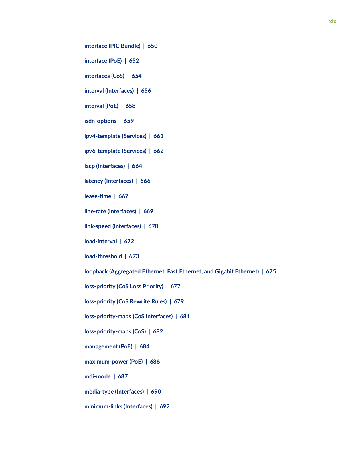
interface (PIC Bundle) | 650 interface (PoE) | 652 interfaces (CoS) | 654 interval (Interfaces) | 656 interval (PoE) | 658

s n ns | 659 ipv4-template (Services) | 661 ipv6-template (Services) | 662 lacp (Interfaces) | 664 latency (Interfaces) | 666

sm | 667

line-rate (Interfaces) | 669 link-speed (Interfaces) | 670 load-interval | 672 load-threshold | 673

loopback (Aggregated Ethernet, Fast Ethernet, and Gigabit Ethernet) | 675 loss-priority (CoS Loss Priority) | 677

loss-priority (CoS Rewrite Rules) | 679 loss-priority-maps (CoS Interfaces) | 681 loss-priority-maps (CoS) | 682 management (PoE) | 684 maximum-power (PoE) | 686

mdi-mode | 687

media-type (Interfaces) | 690 minimum-links (Interfaces) | 692

xx

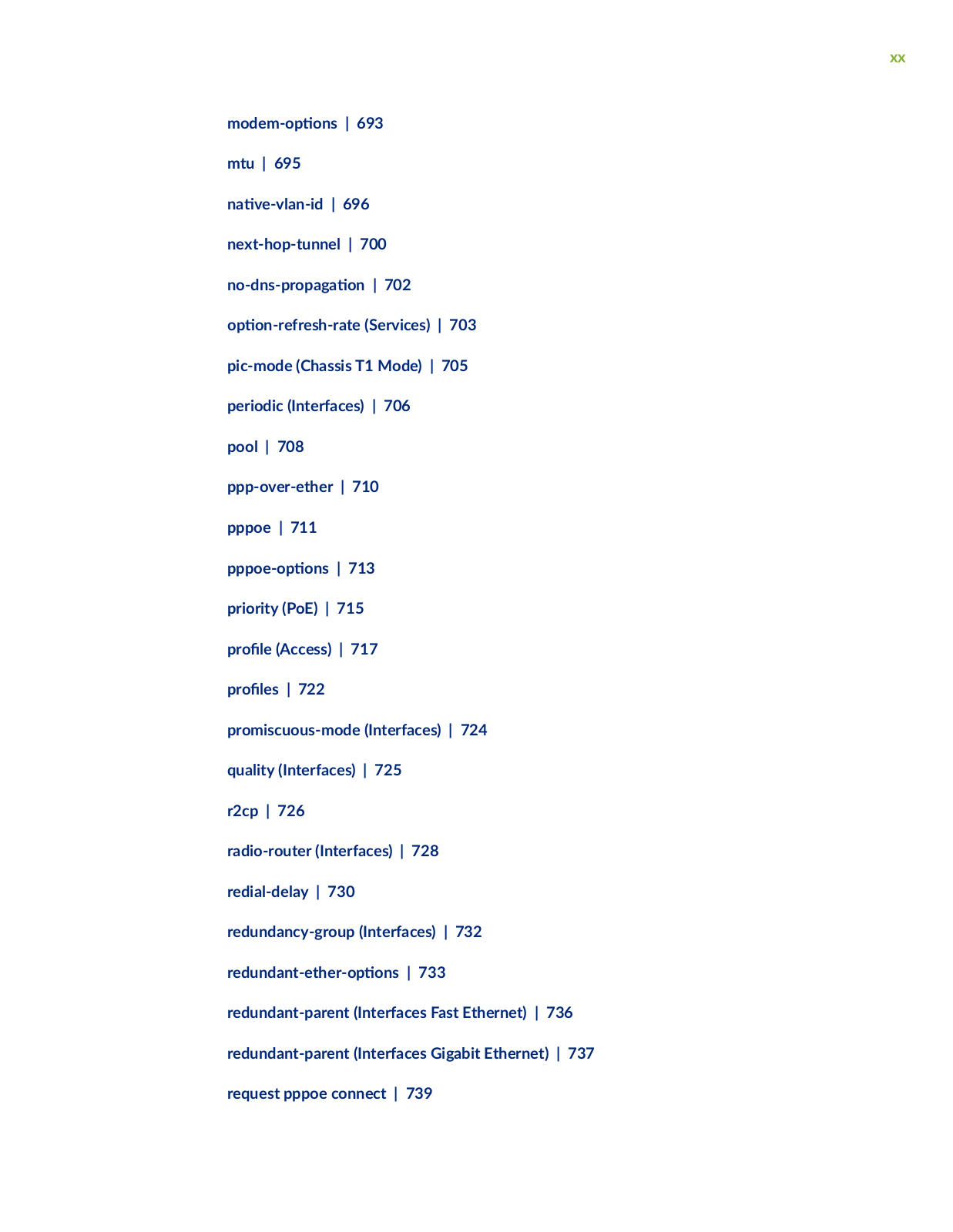
m

m


ns | 693

mtu | 695


n

v v

n

| 696

next-hop-tunnel | 700

n

ns

r

n | 702


n r

r s

r (Services) | 703

pic-mode (Chassis T1 Mode) | 705 periodic (Interfaces) | 706

pool | 708 ppp-over-ether | 710 pppoe | 711

ns | 713 priority (PoE) | 715

r(Access) | 717

rs | 722

promiscuous-mode (Interfaces) | 724

quality (Interfaces) | 725

r2cp | 726

radio-router (Interfaces) | 728 redial-delay | 730 redundancy-group (Interfaces) | 732

r n n r ns | 733

redundant-parent (Interfaces Fast Ethernet) | 736

redundant-parent (Interfaces Gigabit Ethernet) | 737 request pppoe connect | 739

xxi

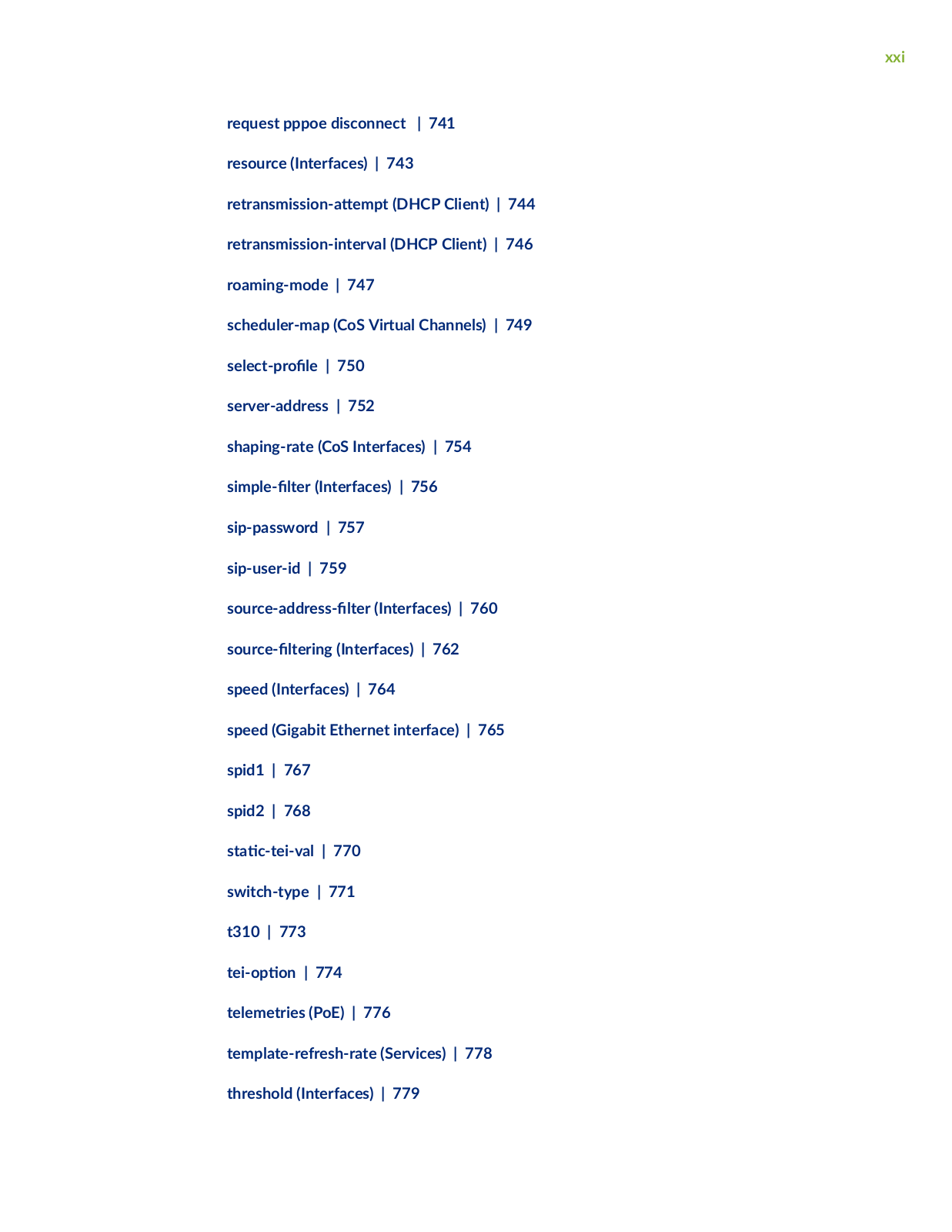
request pppoe disconnect | 741 resource (Interfaces) | 743

r r nsm ss n m (DHCP Client) | 744

retransmission-interval (DHCP Client) | 746 roaming-mode | 747

scheduler-map (CoS Virtual Channels) | 749

s

c r

| 750

server-address | 752

shaping-rate (CoS Interfaces) | 754

s m


r (Interfaces) | 756

sip-password | 757

sip-user-id | 759

s

rc

r ss

r (Interfaces) | 760

s

rc

r n

(Interfaces) | 762

speed (Interfaces) | 764

speed (Gigabit Ethernet interface) | 765 spid1 | 767

spid2 | 768

s c

v | 770

switch-type | 771

t310 | 773


n | 774

telemetries (PoE) | 776

template-refresh-rate (Services) | 778 threshold (Interfaces) | 779

xxii

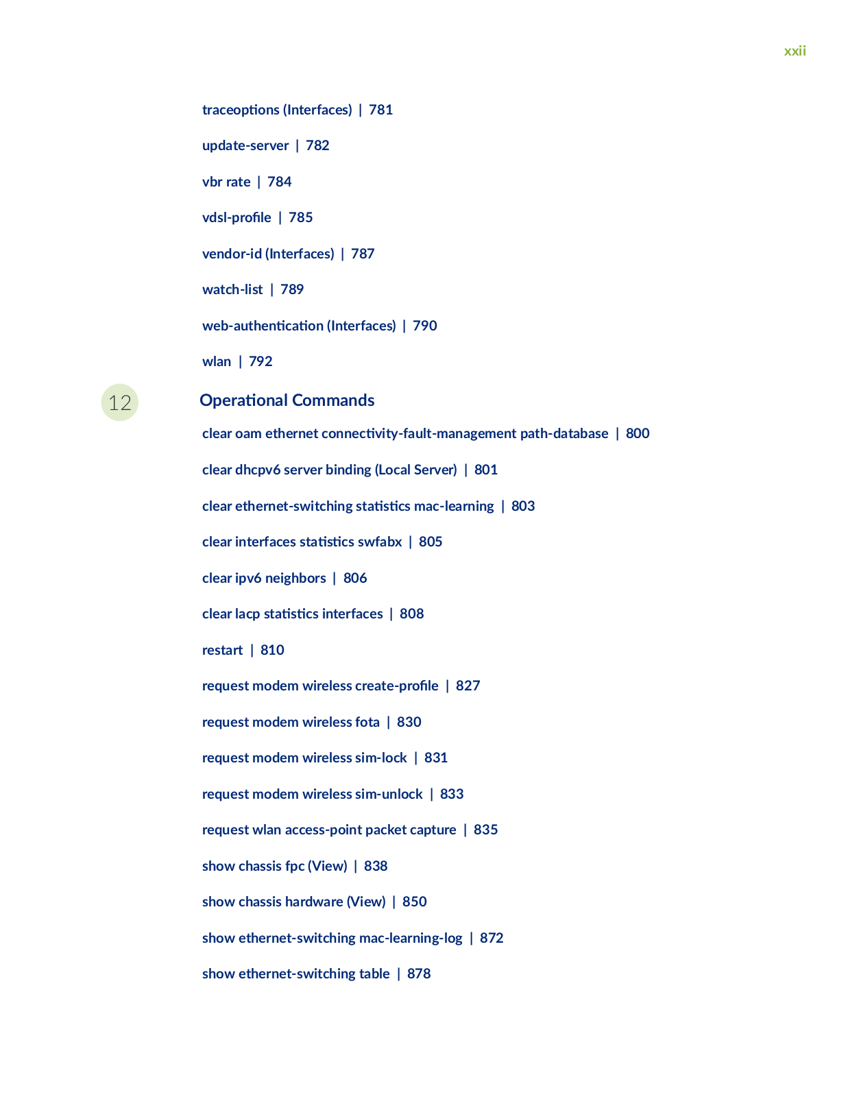
r c

ns (Interfaces) | 781

update-server | 782

vbr rate | 784

v s r

| 785

vendor-id (Interfaces) | 787

watch-list | 789

w b

n c n (Interfaces) | 790

wlan | 792

12

r

n

Commands


clear oam ethernet c nn c v

y


m n m n path-database | 800


clear dhcpv6 server binding (Local Server) | 801


clear ethernet-switching s

s

cs mac-learning | 803


clear interfaces s

s cs swfabx | 805


clear ipv6 neighbors | 806


clear lacp s

s

cs interfaces | 808


restart | 810


request modem wireless cr


r

| 827


request modem wireless fota | 830


request modem wireless sim-lock | 831


request modem wireless sim-unlock | 833


request wlan access-point packet capture | 835


show chassis fpc (View) | 838


show chassis hardware (View) | 850


show ethernet-switching mac-learning-log | 872 show ethernet-switching table | 878

xxiii

show igmp-snooping route (View) | 913

show interfaces | 916


show interfaces

n

s

cs

cs | 1054

show interfaces fl

w s


s cs | 1061

show interfaces queue | 1069


show interfaces s

s

cs (View) | 1076

show interfaces terse zone | 1078

show ipv6 neighbors | 1079


show lacp interfaces (View) | 1082

show lacp s

s cs interfaces (View) | 1089

show modem wireless

rmw r

| 1092

show modem wireless network | 1096

show modem wireless

r

s | 1101

show oam ethernet link-fault-management | 1104

show poe controller (View) | 1113

show pppoe interfaces | 1115


show pppoe s

s

cs | 1121


show poe telemetries | 1125


show services

cc

n

n

| 1128

show services

cc

n

n

r

n (View) | 1132

show services

cc

n

n

r

n template (View) | 1134

show services

cc

n

n

fl w

(View) | 1135

show wlan access-points | 1137 speed (Chassis Cluster) | 1145

xxiv

About This Guide

Use this guide to c n

r and monitor Network, Services, and Special interfaces for Juniper security

devices.


Refer to LTE interfaces and Wi-Fi Mini-PIM interfaces on SRX300, SRX320, SRX340, SRX345, SRX550, and SRX550 HM devices.

Also, understand and c n r the physical, logical and VLAN interfaces, DS1 and DS3 interfaces, ADSL, SHDSL, and VDSL interfaces, Ethernet Interfaces, interface nc s n link service interfaces, management, discard, and loopback interfaces, and serial interfaces on SRX300, SRX320, SRX340, SRX345, SRX550, and SRX550 HM devices.

• Refer to Interfaces Support for SRX100, SRX110, SRX210, SRX240, SRX550, SRX650, and SRX1400 Devices s c n to access n rm n on modem interfaces and 1-Port Clear Channel DS3/E3 GPIM interfaces.

• Refer to Interfaces Fundamentals for n rm

n on serial interfaces.

Juniper Interfaces for Security Devices User Manual

1

CHAPTER

Overview

n r

c

n to Interfaces

|

2


Physical Interface

r

r

s

|

16

Logical Interface

r

r

s

|

26

Understanding IPv4 and IPv6 Protocol Family | 29

C n

r n

VLAN Tagging | 39


2

n r c n to Interfaces

IN THIS SECTION


Understanding Interfaces |

2


Network Interfaces |

3


Services Interfaces |

5


Special Interfaces |

9

ns | 10


Interface Naming C

nv n


Understanding the Data Link Layer | 13

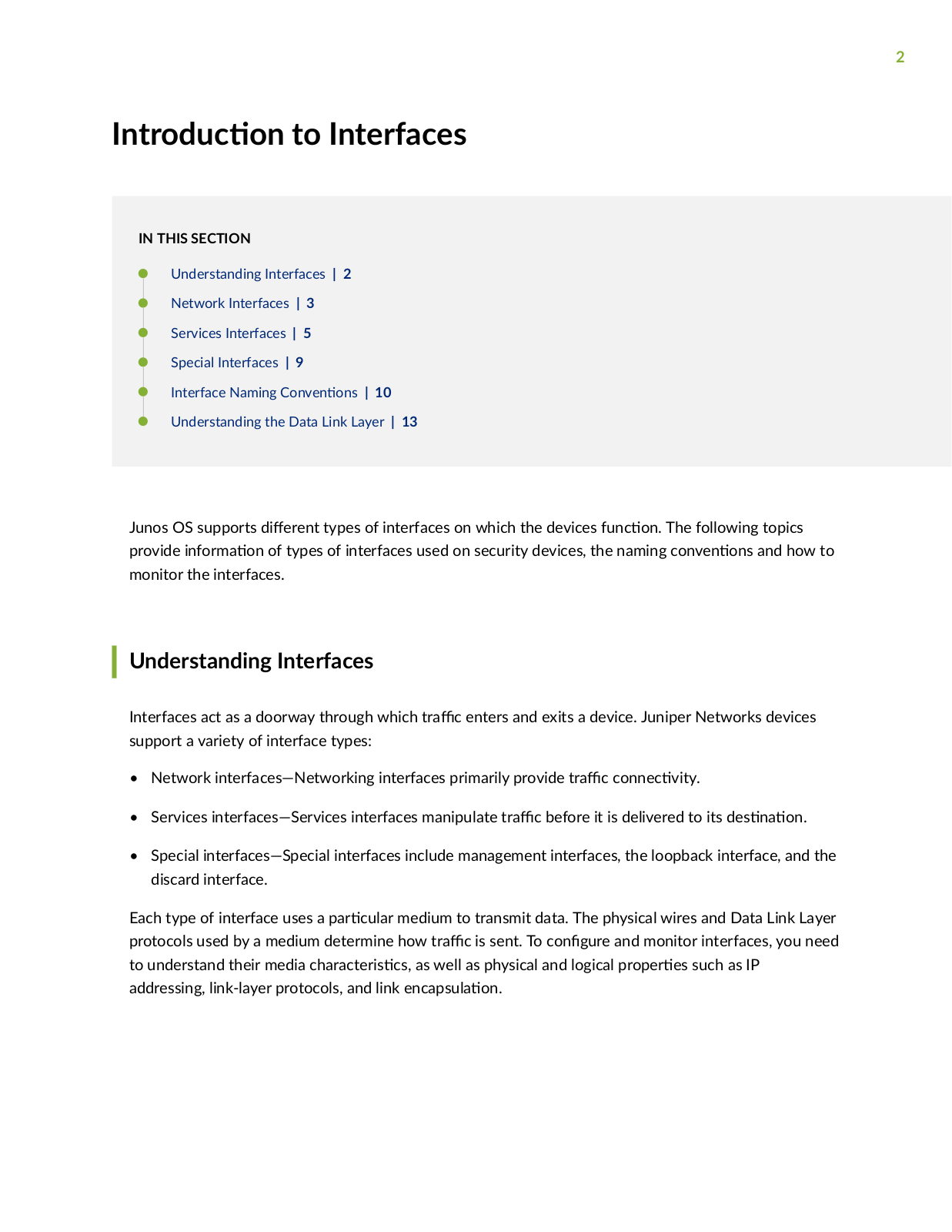
Junos OS supports

r n types of interfaces on which the devices nc n The following topics

provide n rm

n of types of interfaces used on security devices, the naming c nv n ns and how to

monitor the interfaces.


Understanding Interfaces

Interfaces act as a doorway through which r c enters and exits a device. Juniper Networks devices support a variety of interface types:

Network interfaces—Networking interfaces primarily provide r c c nn c v y


Services interfaces—Services interfaces manipulate r c before it is delivered to its s n

n

Special interfaces—Special interfaces include management interfaces, the loopback interface, and the discard interface.

Each type of interface uses a

r c

r medium to transmit data. The physical wires and Data Link Layer

protocols used by a medium determine how

r

c is sent. To c n

r

and monitor interfaces, you need

to understand their media c

r c

r s cs as well as physical and logical

r

r s such as IP

addressing, link-layer protocols, and link nc

s

n


3

NOTE: Most interfaces are c n r b but some internally generated interfaces are not c n r b

Network Interfaces

All Juniper Networks devices use network interfaces to make physical c nn c ns to other devices. A

c nn c

n takes place along m

s

c c physical wires through an I/O card (IOC) in the SRX Series

Services Gateway. Networking interfaces primarily provide r c c

nn c v y


You must c n

r each network interface before it can operate on the device. C n

r n an interface

can

n both the physical r

r

s of the link and the logical r

r s of a logical interface on the

link.


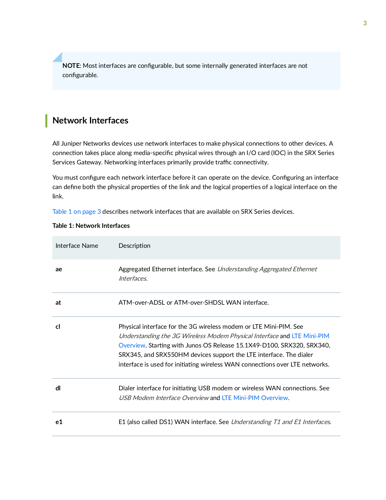
Table 1 on page 3 describes network interfaces that are available on SRX Series devices.

Table 1: Network Interfaces

Interface Name

scr

n


ae

Aggregated Ethernet interface. See Understanding Aggregated Ethernet


Interfaces.


at

ATM-over-ADSL or ATM-over-SHDSL WAN interface.


cl

Physical interface for the 3G wireless modem or LTE Mini-PIM. See


Understanding the 3G Wireless Modem Physical Interface and LTE Mini-PIM


Overview. S r n with Junos OS Release 15.1X49-D100, SRX320, SRX340,


SRX345, and SRX550HM devices support the LTE interface. The dialer


interface is used for n

n

wireless WAN c nn c ns over LTE networks.


dl

Dialer interface for n

n

USB modem or wireless WAN c nn c ns See


USB Modem Interface Overview and LTE Mini-PIM Overview.

e1

E1 (also called DS1) WAN interface. See Understanding T1 and E1 Interfaces.


4

Table 1: Network Interfaces (C n

n )


Interface Name

scr

n


e3

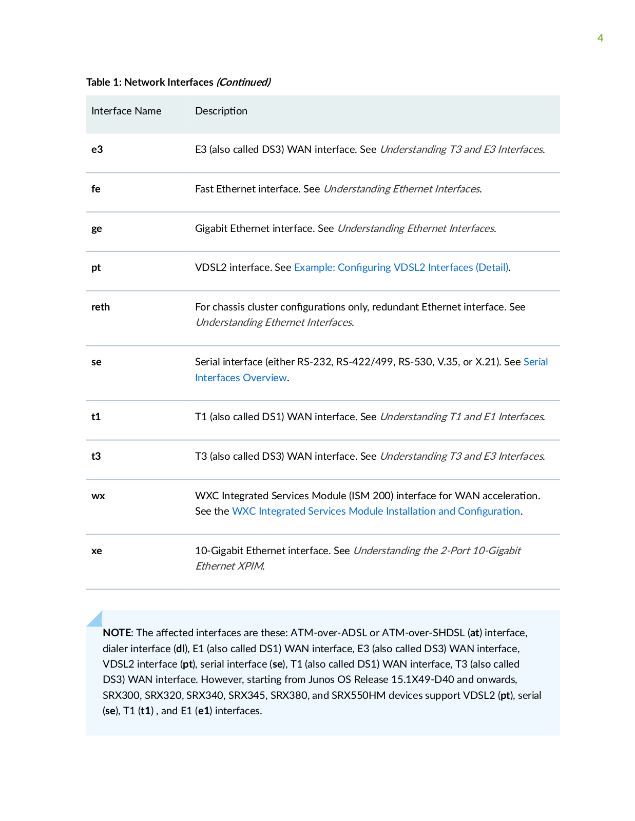
E3 (also called DS3) WAN interface. See Understanding T3 and E3 Interfaces.


fe

Fast Ethernet interface. See Understanding Ethernet Interfaces.


ge

Gigabit Ethernet interface. See Understanding Ethernet Interfaces.


pt

VDSL2 interface. See Example: C n r n VDSL2 Interfaces (Detail).


reth

For chassis cluster c n r ns only, redundant Ethernet interface. See


Understanding Ethernet Interfaces.


se

Serial interface (either RS-232, RS-422/499, RS-530, V.35, or X.21). See Serial


Interfaces Overview.


t1

T1 (also called DS1) WAN interface. See Understanding T1 and E1 Interfaces.


t3

T3 (also called DS3) WAN interface. See Understanding T3 and E3 Interfaces.


wx

WXC Integrated Services Module (ISM 200) interface for WAN

cc r

n


See the WXC Integrated Services Module ns

n and C n

r

n.


xe

10-Gigabit Ethernet interface. See Understanding the 2-Port 10-Gigabit


Ethernet XPIM.


NOTE: The c interfaces are these: ATM-over-ADSL or ATM-over-SHDSL (at) interface, dialer interface (dl), E1 (also called DS1) WAN interface, E3 (also called DS3) WAN interface, VDSL2 interface (pt), serial interface (se), T1 (also called DS1) WAN interface, T3 (also called DS3) WAN interface. However, s r n from Junos OS Release 15.1X49-D40 and onwards, SRX300, SRX320, SRX340, SRX345, SRX380, and SRX550HM devices support VDSL2 (pt), serial (se), T1 (t1) , and E1 (e1) interfaces.

5

Services Interfaces

Services interfaces provide s c c c b

s for m

n

n

r

c before it is delivered to its

s n

n On Juniper Networks M Series and T Series r

n


rms individual services such as

IP-over-IP nc s

n link services such as m

n

protocols,

v services such as stateful

r w

rs and NAT, and sampling and logging c


b

s are implemented by services Physical

Interface Cards (PICs). On SRX Series devices, services processing is handled by the Services Processing Card (SPC).

Although the same Junos OS image supports the services features across all r

n

rms on SRX

Series devices, services interfaces are not associated with a physical interface. To c n

r services on

these devices, you c

n r one or more internal interfaces by specifying slot 0, interface carrier 0, and

port 0—for example, gr-0/0/0 for GRE.


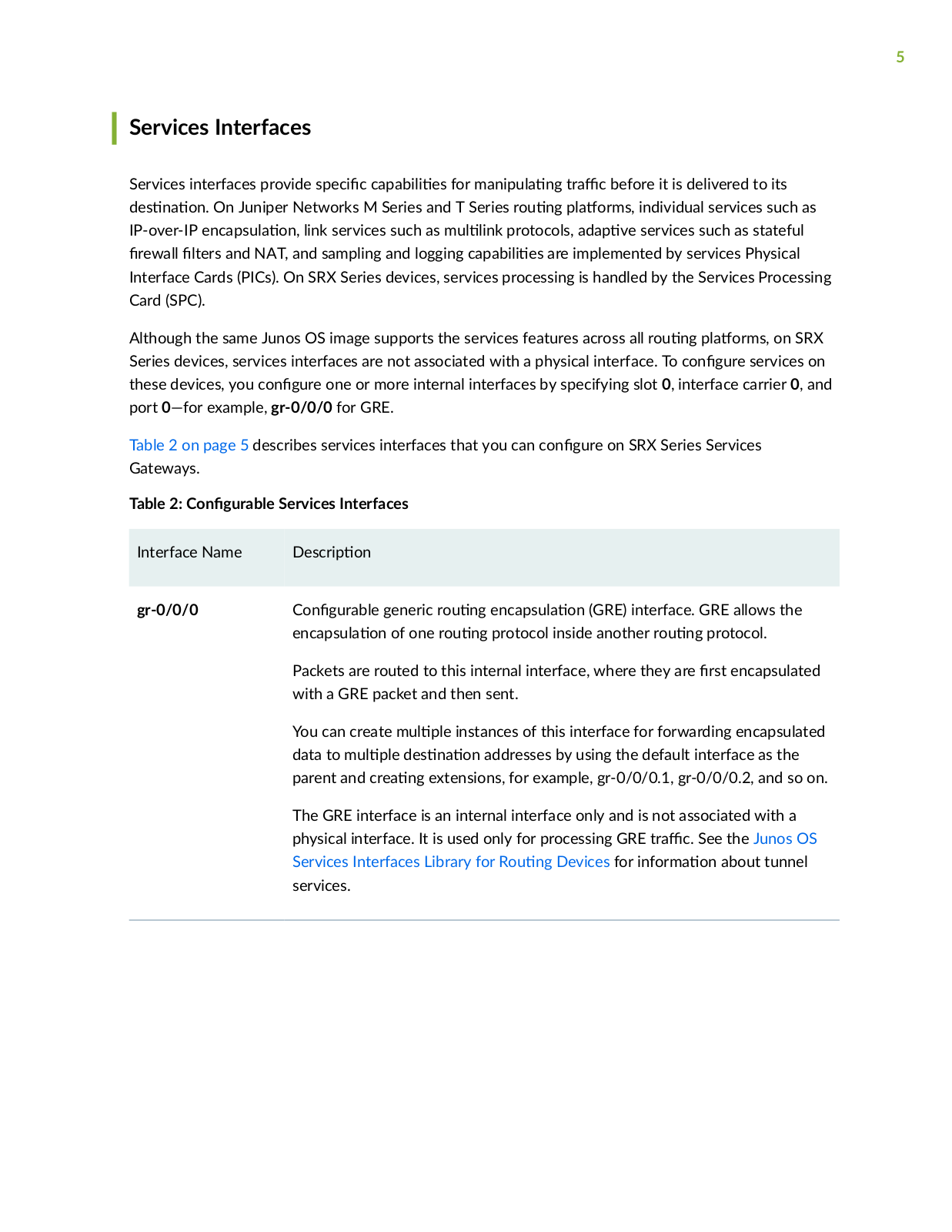
Table 2 on page 5 describes services interfaces that you can c n r on SRX Series Services

Gateways.


Table 2: C n

r b

Services Interfaces


Interface Name

scr

n


gr-0/0/0

C n

r b generic r


nc s

n of one r

n

nc s

n (GRE) interface. GRE allows the

n

protocol inside another r

n protocol.

Packets are routed to this internal interface, where they are rs encapsulated with a GRE packet and then sent.

You can create m


instances of this interface for forwarding encapsulated

data to m


s n

n addresses by using the default interface as the

parent and cr

n

extensions, for example, gr-0/0/0.1, gr-0/0/0.2, and so on.

The GRE interface is an internal interface only and is not associated with a

physical interface. It is used only for processing GRE

r

c See the Junos OS

Services Interfaces Library for R

n Devices for n

rm

n about tunnel

services.


6

Table 2: C n

r b

Services Interfaces (C

n

n

)


Interface Name

scr

n


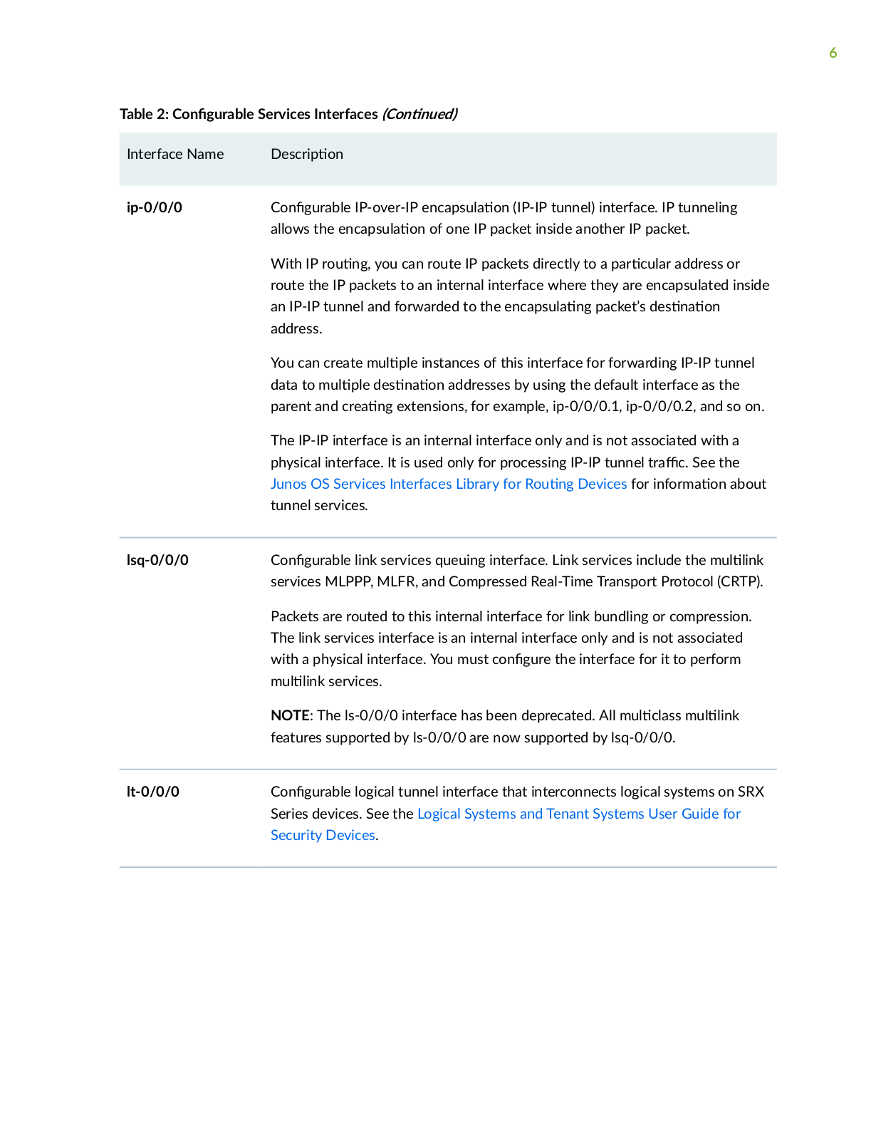
ip-0/0/0


C n

r b

IP-over-IP

nc

s

n (IP-IP tunnel) interface. IP tunneling


allows the

nc

s

n of one IP packet inside another IP packet.


With IP r

n

you can route IP packets directly to a r c


r address or


route the IP packets to an internal interface where they are encapsulated inside


an IP-IP tunnel and forwarded to the

nc

s

n packet’s


s n

n


address.


You can create m


instances of this interface for forwarding IP-IP tunnel


data to m


s

n

n addresses by using the default interface as the


parent and cr

n

extensions, for example, ip-0/0/0.1, ip-0/0/0.2, and so on.


The IP-IP interface is an internal interface only and is not associated with a


physical interface. It is used only for processing IP-IP tunnel

r

c See the


Junos OS Services Interfaces Library for R

n

Devices for n

rm

n about


tunnel services.


lsq-0/0/0


C n

r b

link services queuing interface. Link services include the m

n


services MLPPP, MLFR, and Compressed Real-Time Transport Protocol (CRTP).


Packets are routed to this internal interface for link bundling or compression.


The link services interface is an internal interface only and is not associated


with a physical interface. You must c

n

r the interface for it to perform


m

n services.


NOTE: The ls-0/0/0 interface has been deprecated. All m

c

ss m

n


features supported by ls-0/0/0 are now supported by lsq-0/0/0.


lt-0/0/0


C n

r b

logical tunnel interface that interconnects logical systems on SRX


Series devices. See the Logical Systems and Tenant Systems User Guide for


Security Devices.


Loading...
+ 1141 hidden pages