Juniper Hierarchical Class User Manual

Junos® OS

Hierarchical Class of Service User Guide

Published

2021-04-17

ii

Juniper Networks, Inc. 1133 nn v n Way Sunnyvale, California 94089 USA

408-745-2000 www.juniper.net

Juniper Networks, the Juniper Networks logo, Juniper, and Junos are registered trademarks of Juniper Networks, Inc. in the United States and other countries. All other trademarks, service marks, registered marks, or registered service marks are the property of their r s c v owners.

Juniper Networks assumes no responsibility for any inaccuracies in this document. Juniper Networks reserves the right

to change, modify, transfer, or otherwise revise this b c

n without n c

Junos® OS Hierarchical Class of Service User Guide


Copyright © 2021 Juniper Networks, Inc. All rights reserved.


The n rm

n in this document is current as of the date on the

page.

YEAR 2000 NOTICE

Juniper Networks hardware and s ftw r products are Year 2000 compliant. Junos OS has no known m r

m ns through the year 2038. However, the NTP c n is known to have some c y in the year 2036.

END USER LICENSE AGREEMENT

The Juniper Networks product that is the subject of this technical

c m n

n consists of (or is intended for use

with) Juniper Networks s ftw r

Use of such s

ftw r

is subject to the terms and c n

ns of the End User License

Agreement ("EULA") posted at

s s

r

n r n

s

r

. By downloading, installing or using such

s ftw r you agree to the terms and c n

ns of that EULA.


iii

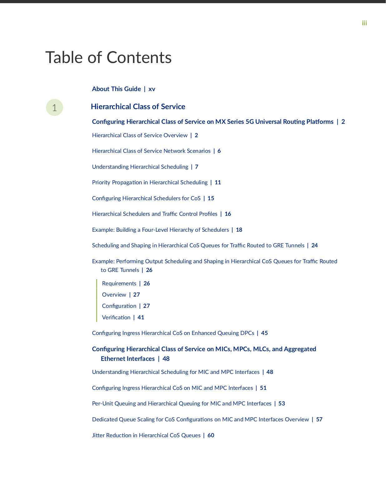
Table of Contents

About This Guide | xv

1Hierarchical Class of Service

C n

r n

Hierarchical Class of Service on MX Series 5G Universal R

n

rms | 2

Hierarchical Class of Service Overview |

2


Hierarchical Class of Service Network Scenarios |

6


Understanding Hierarchical Scheduling |

7


Priority

r

n in Hierarchical Scheduling | 11


C n

r n

Hierarchical Schedulers for CoS | 15


Hierarchical Schedulers and r c Control

r

s | 16


Example: Building a Four-Level Hierarchy of Schedulers | 18


Scheduling and Shaping in Hierarchical CoS Queues for r c Routed to GRE Tunnels | 24

Example: Performing Output Scheduling and Shaping in Hierarchical CoS Queues for r

c Routed


to GRE Tunnels | 26


Requirements | 26


Overview | 27


C n

r n | 27


r

c

n | 41


C n

r n

Ingress Hierarchical CoS on Enhanced Queuing DPCs | 45


C n

r n

Hierarchical Class of Service on MICs, MPCs, MLCs, and Aggregated


Ethernet Interfaces | 48


Understanding Hierarchical Scheduling for MIC and MPC Interfaces | 48


C n

r n

Ingress Hierarchical CoS on MIC and MPC Interfaces | 51


Per-Unit Queuing and Hierarchical Queuing for MIC and MPC Interfaces | 53


Dedicated Queue Scaling for CoS C n

r

ns on MIC and MPC Interfaces Overview | 57


r R

c

n in Hierarchical CoS Queues | 60


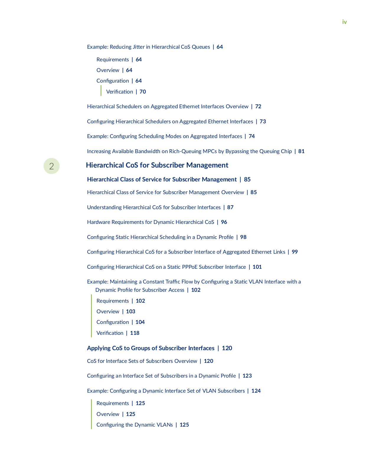
iv

Example: Reducing

r in Hierarchical CoS Queues | 64

Requirements | 64


Overview | 64


C n

r

n | 64


r

c

n | 70


Hierarchical Schedulers on Aggregated Ethernet Interfaces Overview | 72

C n r n

Hierarchical Schedulers on Aggregated Ethernet Interfaces | 73

Example: C

n r n Scheduling Modes on Aggregated Interfaces | 74

Increasing Available Bandwidth on Rich-Queuing MPCs by Bypassing the Queuing Chip | 81

2Hierarchical CoS for Subscriber Management

Hierarchical Class of Service for Subscriber Management | 85

Hierarchical Class of Service for Subscriber Management Overview | 85

Understanding Hierarchical CoS for Subscriber Interfaces | 87

Hardware Requirements for Dynamic Hierarchical CoS | 96


C

n

r n

S c Hierarchical Scheduling in a Dynamic r

| 98

C

n

r n

Hierarchical CoS for a Subscriber Interface of Aggregated Ethernet Links | 99

C

n

r n

Hierarchical CoS on a S c PPPoE Subscriber Interface | 101

Example: Maintaining a Constant r c Flow by C n r n a S c VLAN Interface with a

Dynamic

r


for Subscriber Access | 102

Requirements |

102

Overview | 103

C n

r


n |

104

r

c

n | 118

Applying CoS to Groups of Subscriber Interfaces | 120

CoS for Interface Sets of Subscribers Overview | 120

C n r n

an Interface Set of Subscribers in a Dynamic r

| 123

Example: C

n

r n a Dynamic Interface Set of VLAN Subscribers | 124


Requirements | 125


Overview | 125


C n

r n

the Dynamic VLANs | 125


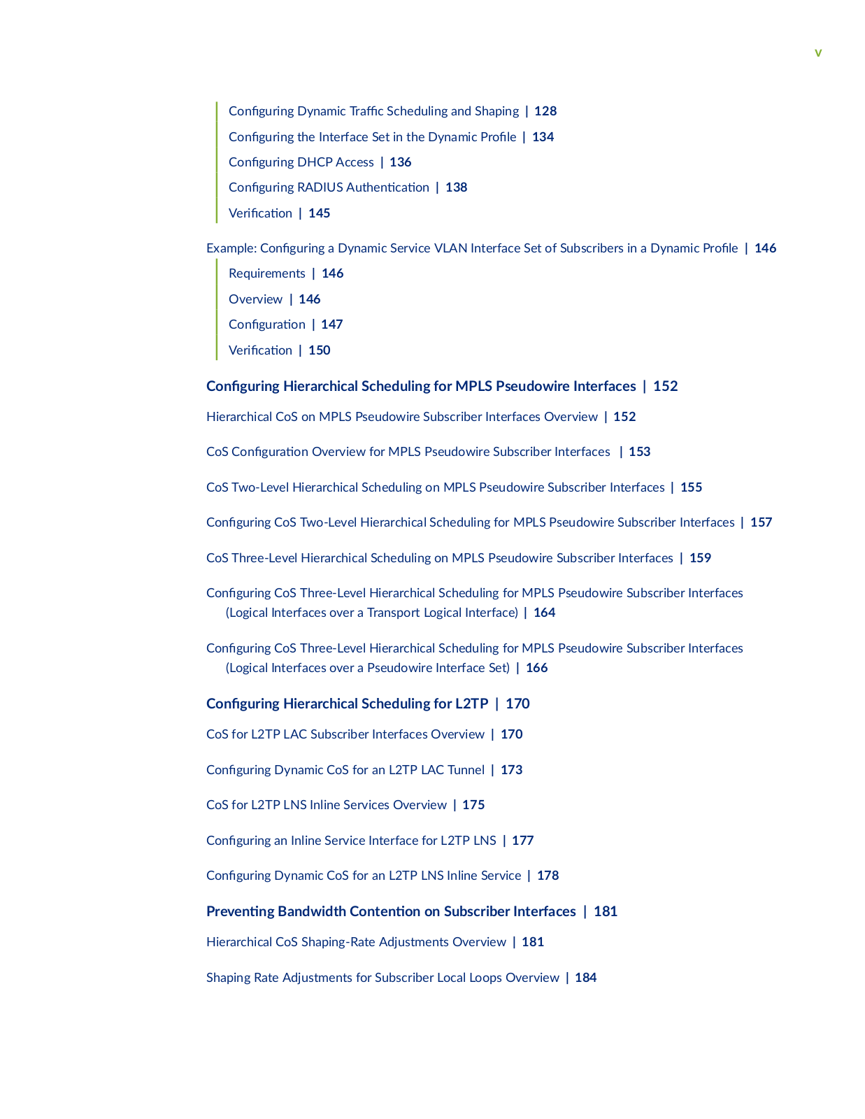
v


C

n

r n

Dynamic r

c Scheduling and Shaping | 128


C

n

r n

the Interface Set in the Dynamic r

| 134


C n

r n

DHCP Access | 136


C n

r n

RADIUS

n c

n | 138


r c

n | 145


Example: C

n

r n a Dynamic Service VLAN Interface Set of Subscribers in a Dynamic r

| 146


Requirements | 146


Overview | 146


C n

r

n | 147


r c

n | 150


C

n

r n

Hierarchical Scheduling for MPLS Pseudowire Interfaces | 152


Hierarchical CoS on MPLS Pseudowire Subscriber Interfaces Overview | 152


CoS C

n

r

n Overview for MPLS Pseudowire Subscriber Interfaces | 153


CoS Two-Level Hierarchical Scheduling on MPLS Pseudowire Subscriber Interfaces | 155


C

n

r n

CoS Two-Level Hierarchical Scheduling for MPLS Pseudowire Subscriber Interfaces | 157

CoS Three-Level Hierarchical Scheduling on MPLS Pseudowire Subscriber Interfaces | 159


C

n

r n

CoS Three-Level Hierarchical Scheduling for MPLS Pseudowire Subscriber Interfaces


(Logical Interfaces over a Transport Logical Interface) | 164


C

n

r n

CoS Three-Level Hierarchical Scheduling for MPLS Pseudowire Subscriber Interfaces


(Logical Interfaces over a Pseudowire Interface Set) | 166


C

n

r n

Hierarchical Scheduling for L2TP | 170


CoS for L2TP LAC Subscriber Interfaces Overview | 170


C n

r n

Dynamic CoS for an L2TP LAC Tunnel | 173


CoS for L2TP LNS Inline Services Overview | 175


C

n

r n

an Inline Service Interface for L2TP LNS | 177


C n

r n

Dynamic CoS for an L2TP LNS Inline Service | 178


r v n n

Bandwidth C

n n

n on Subscriber Interfaces | 181


Hierarchical CoS Shaping-Rate Adjustments Overview | 181

Shaping Rate Adjustments for Subscriber Local Loops Overview | 184

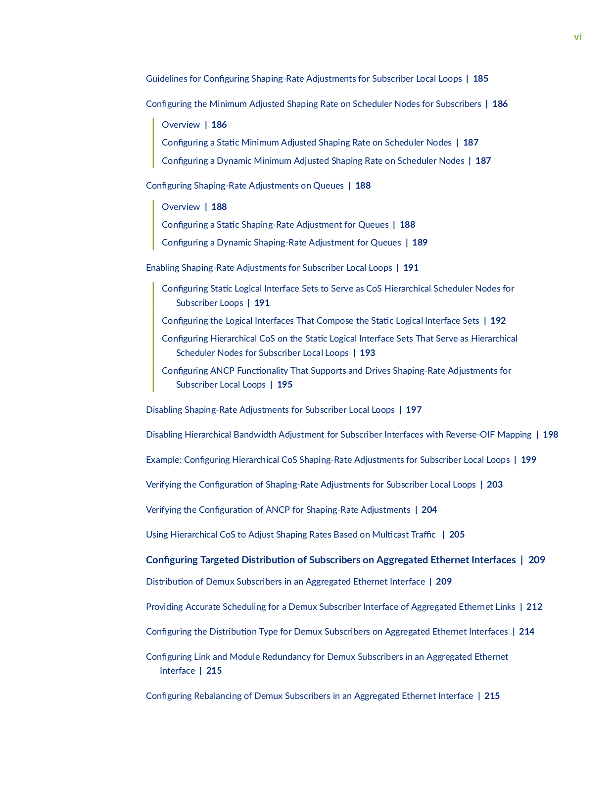
vi

Guidelines for C

n

r n Shaping-Rate Adjustments for Subscriber Local Loops | 185

C n

r n

the Minimum Adjusted Shaping Rate on Scheduler Nodes for Subscribers | 186


Overview | 186

c Minimum Adjusted Shaping Rate on Scheduler Nodes | 187


C n

r n

a S


C n

r n

a Dynamic Minimum Adjusted Shaping Rate on Scheduler Nodes | 187

C n

r n

Shaping-Rate Adjustments on Queues | 188

Overview | 188

C n r n a S c Shaping-Rate Adjustment for Queues | 188

C n r n a Dynamic Shaping-Rate Adjustment for Queues | 189

Enabling Shaping-Rate Adjustments for Subscriber Local Loops | 191

C

n

r n

S c Logical Interface Sets to Serve as CoS Hierarchical Scheduler Nodes for


Subscriber Loops | 191

C

n

r n

the Logical Interfaces That Compose the S c Logical Interface Sets | 192

C

n

r n

Hierarchical CoS on the S c Logical Interface Sets That Serve as Hierarchical


Scheduler Nodes for Subscriber Local Loops | 193

C n

r n

ANCP nc n y That Supports and Drives Shaping-Rate Adjustments for


Subscriber Local Loops | 195

Disabling Shaping-Rate Adjustments for Subscriber Local Loops | 197

Disabling Hierarchical Bandwidth Adjustment for Subscriber Interfaces with Reverse-OIF Mapping | 198

Example: C n


r n Hierarchical CoS Shaping-Rate Adjustments for Subscriber Local Loops | 199

Verifying the C

n

r

n of Shaping-Rate Adjustments for Subscriber Local Loops | 203

Verifying the C

n

r

n of ANCP for Shaping-Rate Adjustments | 204

Using Hierarchical CoS to Adjust Shaping Rates Based on M c s r c | 205

C n

r n Targeted

s r b

n of Subscribers on Aggregated Ethernet Interfaces | 209

s r b

n of Demux Subscribers in an Aggregated Ethernet Interface | 209

Providing Accurate Scheduling for a Demux Subscriber Interface of Aggregated Ethernet Links | 212

C

n

r n

the s r b

n Type for Demux Subscribers on Aggregated Ethernet Interfaces | 214

C n

r n Link and Module Redundancy for Demux Subscribers in an Aggregated Ethernet


Interface | 215


C

n

r n

Rebalancing of Demux Subscribers in an Aggregated Ethernet Interface | 215

vii


C

n

r n

Periodic Rebalancing of Subscribers in an Aggregated Ethernet Interface | 216


C

n

r n

Manual Rebalancing of Subscribers on an Aggregated Ethernet Interface | 216

Example: S

r

n Targeted M c s r c for Demux Subscribers on Aggregated Ethernet

Interfaces | 217

Requirements | 218

Overview | 218

C n r n | 219 r c n | 227

Verifying the

s r b

n of Demux Subscribers in an Aggregated Ethernet Interface | 232

C n r n the

s r b

n Type for PPPoE Subscribers on Aggregated Ethernet Interfaces | 233

Verifying the

s r b

n of PPPoE Subscribers in an Aggregated Ethernet Interface | 234

Applying CoS Using Parameters Received from RADIUS | 236

Subscriber Interfaces That Provide n CoS Parameters Dynamically Obtained from RADIUS | 236

Changing CoS Services Overview | 241


CoS r

c Shaping


r b s for Dynamic Interface Sets and Member Subscriber Sessions


Overview | 247


Guidelines for C

n


r n CoS

r c Shaping

r b s for Dynamic Interface Sets and Member


Subscriber Sessions | 249


C n

r n

n

CoS Parameters Dynamically Obtained from RADIUS | 250


C n

r n

S

c Default Values for r

c Scheduling and Shaping | 251


Applying CoS r

c S

n

r b s to Dynamic Interface Sets and Member Subscriber


Sessions | 253


CoS r

c Shaping

r

n

Variables for Dynamic Interface Sets | 256


Example: C

n

r n

Dynamic Hierarchical Scheduling for Subscribers | 263

3

C n

r


n Statements and

r

n Commands


C n

r

n Statements | 275


accept | 280

address-assignment (Address-Assignment Pools) | 282

n c n (DHCP Local Server) | 285

viii

n

c

n (DHCP Relay Agent) | 287

n

c

n

r r | 289

c

n

r

| 291

adjust-minimum | 294 adjust-percent | 295 atm-service | 296

br s z (Schedulers) | 298

cbr | 300


c ss rs (

n n) | 302

css rs (Logical Interface) | 304

css rs (Physical Interface) | 305

code-points (CoS) | 307

y b

r r

| 308

demux0 (Dynamic Interface) | 310

m x

ns (Dynamic Interface) | 313

demux-source (Dynamic IP Demux Interface) | 314 demux-source (Dynamic Underlying Interface) | 315 demux-source (Underlying Interface) | 317

cr b s (Address-Assignment Pools) | 318

dhcp-local-server | 325 dhcp-relay | 338

drop-probability (Interpolated Value) | 355 drop-probability (Percentage) | 356

rr (Schedulers) | 358

r

r

m

(Schedulers) | 359

r

r

s |

360

ix

dscp (CoS C ss


rs) | 362


dscp (Rewrite Rules) | 363


dscp-ipv6 (CoS Rewrite Rules) | 365

yn m c

r

(DHCP Local Server) | 367

yn m c

r

(VLAN) | 369


yn m c

r

s | 371


egress-shaping-overhead | 385

excess-bandwidth-share | 387


excess-priority | 389


excess-rate (Dynamic r

c Shaping) | 391

excess-rate-high (Dynamic

r

c Shaping) | 392

excess-rate-low (Dynamic

r

c Shaping) | 394

family | 396


family (Address-Assignment Pools) | 402

family (Dynamic Demux Interface) | 404

family (Dynamic PPPoE) | 406


family (Dynamic Standard Interface) | 408

v

(Drop

r

s) | 411


v(Interpolated Value) | 412

r (C

n

r n )

| 414

fl x b

v n

n

| 416

forwarding-classes (Class-of-Service) | 417 group (DHCP Local Server) | 419

guaranteed-rate | 424 hierarchical-scheduler | 426

hierarchical-scheduler (Subscriber Interfaces on MX Series Routers) | 428

x

ieee-802.1ad | 430


inet-precedence (CoS C ss

rs) | 432

input-excess-bandwidth-share | 433


input-scheduler-map | 435


input-shaping-rate (Logical Interface) | 437

input-shaping-rate (Physical Interface)

| 439

n

r

c c

n r

r

| 440


n

r

c c

n r

r

r m n n

| 442

interface (DHCP Local Server) | 444


interface-set (Ethernet Interfaces)

| 447

interface-set (Hierarchical Schedulers)

| 448

interface-set (IP Demux Interfaces) | 450

interfaces

| 451


interfaces (CoS) | 453


interfaces (S

c and Dynamic Subscribers) | 456

internal-node | 463


interpolate | 464


loss-priority (BA C ss

rs)

| 465


loss-priority (Scheduler Drop r

s)

| 467

max-queues | 468


max-queues-per-interface | 471


member-link-scheduler | 473


mode (Layer 2 Tunneling Protocol Shaping) | 475

r

c c

n r

r

|

477

r

c c

n r

r

r

m n n | 479

v r

cc

n n

| 481


xi

pap (Dynamic PPP) | 482 peak-rate | 484 per-unit-scheduler | 485

pool (Address-Assignment Pools) | 487 ns (Dynamic PPPoE) | 490

ns (Dynamic PPP) | 491 priority (Schedulers) | 494

r(Access) | 496

protocols | 503


proxy-arp | 506


qos-adjust-hierarchical | 508


queue (Global Queues) | 510


radius (Access

r

) | 511


radius-server | 516


range (Address-Assignment Pools) | 522


ranges (Dynamic VLAN) | 524


rewrite-rules (

n

n)

| 525


rewrite-rules (Interfaces)

| 527


r n ns nc s (M


R

n

n

s) | 529


scheduler (Scheduler Map) | 532


scheduler-map (Interfaces and

r

c C

n r r

s) | 533

scheduler-maps (For Most Interface Types) | 534


schedulers (CoS) | 536


secret (RADIUS) | 537


server (Dynamic PPPoE) | 539


server-group | 540


xii

shaping-rate (Applying to an Interface) | 542 shaping-rate (Schedulers) | 545

shaping-rate (Oversubscribing an Interface) | 547 shaping-rate-excess-high | 550 shaping-rate-excess-low | 552 shaping-rate-priority-high | 554 shaping-rate-priority-low | 556 shaping-rate-priority-medium | 559 shared-bandwidth-policer (C n r n ) | 561 shared-instance | 562

shared-scheduler | 564

s m

r (Applying to an Interface) | 565

s m

r | 566

sn r (VPLS) | 569

stacked-interface-set (Dynamic

r

s) | 570

stacked-vlan-tagging | 572


term (Simple Filter)

| 573


three-color-policer (Applying) | 575


three-color-policer (C

n r n )

| 577

r

c c n r

r

s

| 579


r

c m n

r | 582


transmit-rate (Schedulers) | 587 transparent | 590

underlying-interface (demux0) | 592 underlying-interface (Dynamic PPPoE) | 593 unit | 595

xiii

unit (Dynamic Demux Interface) | 597 unit (Dynamic PPPoE) | 599

unnumbered-address (Dynamic PPPoE) | 602

unnumbered-address (Dynamic r

s) | 603

unnumbered-address (Ethernet) | 606

s r r x (DHCP Relay Agent) | 608

vlan-id (Dynamic r

s) | 610


vlan-id (VLAN ID to Be Bound to a Logical Interface) | 611 vlan-model | 613

vlan-ranges | 614 vlan-tag | 616 vlan-tags | 617 vlan-tags-outer | 619

vlan-tags (Stacked VLAN Tags) | 620

rn Commands | 625

show access-cac interface-set | 625


show class-of-service

s m n

c n r r

| 628

show class-of-service c

ss r |

631


show class-of-service interface | 634 show class-of-service scheduler-map | 681

show class-of-service scheduler-hierarchy interface | 686 show class-of-service scheduler-hierarchy interface-set | 689 show interfaces | 691

show interfaces (PPPoE) | 830

show interfaces demux0 (Demux Interfaces) | 848 show interfaces queue | 863

xiv

show subscribers | 924

xv

About This Guide

Use this guide to understand and c

n

r hierarchical class of service (CoS) features in Junos OS to

n service levels that provide

r

n delay,

r and packet loss c r c r s cs to r c r

c

ns served by s c c r

c fl

ws Applying CoS features to each device in your network

ensures quality of service (QoS) for

r

c throughout your n r network.

RELATED DOCUMENTATION

The Day One: Deploying Basic QoS

Day One: Dynamic Subscriber Management

1

PART

Hierarchical Class of Service

C

n

r n

Hierarchical Class of Service on MX Series 5G Universal R n


rms | 2

C

n

r n

Hierarchical Class of Service on MICs, MPCs, MLCs, and Aggregated

Ethernet Interfaces | 48

2

CHAPTER 1

C n r n Hierarchical Class of Service on MX Series 5G Universal R n rms

IN THIS CHAPTER


Hierarchical Class of Service Overview | 2


Hierarchical Class of Service Network Scenarios |

6


Understanding Hierarchical Scheduling | 7


Priority

r

n in Hierarchical Scheduling | 11


C n

r n

Hierarchical Schedulers for CoS | 15

s | 16


Hierarchical Schedulers and r c Control r


Example: Building a Four-Level Hierarchy of Schedulers | 18


Scheduling and Shaping in Hierarchical CoS Queues for r c Routed to GRE Tunnels | 24


Example: Performing Output Scheduling and Shaping in Hierarchical CoS Queues for r c Routed to GRE


Tunnels | 26


C n

r n

Ingress Hierarchical CoS on Enhanced Queuing DPCs | 45


Hierarchical Class of Service Overview

Hierarchical class of service (HCoS) is the ability to apply r c schedulers and shapers to a hierarchy of

scheduler nodes. Each level of the scheduler hierarchy can be used to shape r

c based on

r n

criteria such as

c

n user, VLAN, and physical port.


This allows you to support the requirements of

r n services,

c

ns and users on the same

physical device and physical infrastructure.


HCoS is implemented primarily using r c c

ss

rs at the ingress and hierarchical schedulers and

shapers at the egress.


A c ss

r is a

r that labels

r c at the device ingress based on c

n

r b

parameters such as

c

n or

s n

n

r

c is c ss

into what is called a forwarding equivalence class (FEC).

The FEC

n s a class of

r

c that receives common treatment.


3

Schedulers, and their associated shapers, is the

nc n that controls the r c bandwidth,

r (delay

v r

n) and packet loss priority at the egress of the device.


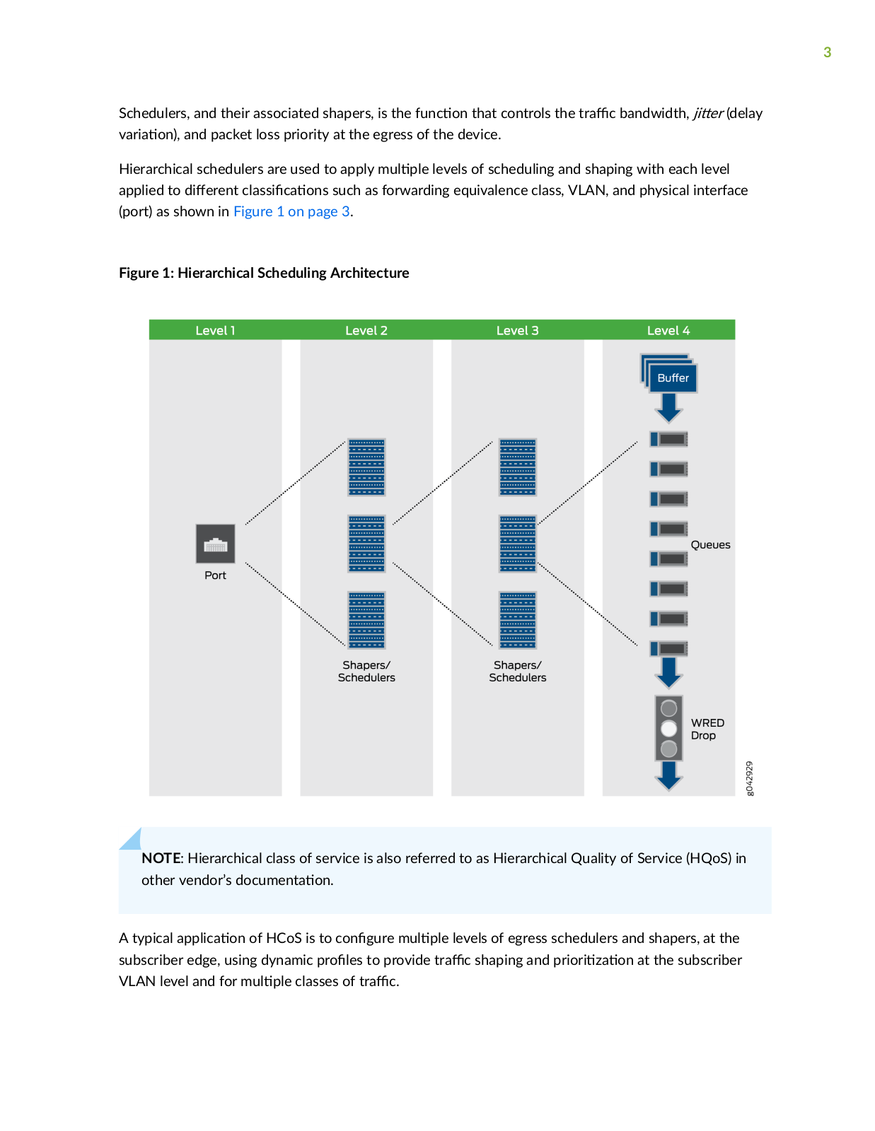
Hierarchical schedulers are used to apply m

levels of scheduling and shaping with each level

applied to

r n c ss c

ns such as forwarding equivalence class, VLAN, and physical interface

(port) as shown in Figure 1 on page 3.


Figure 1: Hierarchical Scheduling Architecture

NOTE: Hierarchical class of service is also referred to as Hierarchical Quality of Service (HQoS) in

other vendor’s

c m n

n


A typical

c

n of HCoS is to c

n

r m

levels of egress schedulers and shapers, at the

subscriber edge, using dynamic r

s to provide r

c shaping and r r z

n at the subscriber

VLAN level and for m

classes of r

c


4

Dynamic r s are a mechanism that allows you to dynamically apply schedulers and shapers to individual subscribers or groups of subscribers.

To learn more about HCoS, the following topics are very helpful:

Junos CoS on MX Series 5G Universal R n

rms Overview

CoS Features and m

ns on MX Series Routers


CoS Features of the Router Hardware, PIC, MIC, and MPC Interface Families

How Schedulers

n Output Queue r r s

Subscriber Access Network Overview

CoS for Subscriber Access Overview

"Hierarchical Class of Service for Subscriber Management Overview" on page 85

The Junos OS hierarchical schedulers support up to v levels of scheduler hierarchies on MX Series devices when using enhanced queuing Dense Port Concentrators (DPCs) or n r n queuing Modular Port Concentrators (MPCs), and Modular Interface Cards (MICs). It is important to know the

c

b

s of your hardware with respect to HCoS. The following are a few s to help you:

Only certain hardware supports the v v scheduler hierarchy of HCoS.

The number of queues and logical interfaces supported is dependent upon exactly what hardware you are using.

The MX Series Packet Forwarding Engine handles guaranteed bandwidth and scheduler node weight r n y than other Packet Forwarding Engines.

• The

n

r

n

queuing MPCs and MICs have a certain granularity with respect to the shaping and

delay b


r values. The values used are not necessarily exactly the values c n r


To learn more about

rm support for HCoS, use the Juniper Networks Feature Explorer (

s

n

r

n

r n

r x r r ). In the Feature Explorer, search on hierarchical schedulers.

In

n it is important to note the following:


• HCoS is most frequently used to enforce service level agreements at the subscriber edged using dynamic r c control r s

Hierarchical schedulers can also be applied to Ethernet pseudowire interfaces, aggregated Ethernet interfaces, Layer 2 Tunnel Protocol (L2TP) network server (LNS) inline services, and GRE tunnels.

• Hierarchical ingress policing is a feature that is complimentary to and ft n used in c n nc n with HCoS.

5

• There are other features in Junos OS that have similar sounding names.

NOTE: The hierarchical scheduler and shaper feature supported on the SRX Series devices is not the HCoS feature described here.

Before planning HCoS for you network, you should learn about HCoS,

n you needs, plan how you

want to implement HCoS, and test the

r

n in a simulated environment.


Table 1: Resources for Learning More About HCoS


Document


scr

n


Day One: Deploying Basic QoS

This book is a good resource for learning the basics of CoS on

Juniper Networks Books

Juniper Networks devices.


Juniper MX-Series O'Reilly Media

Learn about the advanced features of HCoS. This book provides


an in-depth

scr

n of how HCoS works and how it can be


deployed. It also provides a lab tested topology and c

n

r n


example.


Day One: Dynamic Subscriber

Learn how to use HCoS in c n nc

n with dynamic

r

c

Management Juniper Networks

control

r

s for subscriber management. This book also

Books


includes

r

b s

n


QoS Enabled Networks John

This book is an

n source for studying QoS.


Wiley & Sons


c m n

n related to HCoS is consolidated in the Hierarchical Class of Service User Guide.


RELATED DOCUMENTATION

Hierarchical Class of Service for Subscriber Management Overview | 85

Hierarchical Class of Service Network Scenarios

Understanding Hierarchical Scheduling

6

Hierarchical Class of Service Network Scenarios

IN THIS SECTION

Services to Subscribers | 6

Services to Businesses | 7

Wireless Backhaul | 7

Hierarchical class of service (HCoS) can be used to provide granular control of r c for a variety of r n c ns

NOTE: Hierarchical class of service is also referred to as Hierarchical Quality of Service (HQoS) in other vendor’s c m n n

Hierarchical class of service is most frequently used in the following scenarios:

Services to Subscribers

M s rv c network operators face a challenge to provide r n types of services on the same infrastructure to r s n and business subscribers. The network operator needs to make sure each subscriber gets the network resources they paid for and each service gets the network resources it needs to operate properly.

If no CoS is applied, one service could consume most of the bandwidth of the transmission infrastructure and starve the other services.

Using hierarchical class of service, the network edge device can have up to v levels of scheduling and r r z n So the r c can be shaped and r r z per customer and per service type. Controlling r c in this way provides the ability to deliver the required service level for each subscriber for each

service type.


By allowing network operators to consolidate

r n services and m

customers on the same

physical infrastructure, hierarchical class of service helps maximize the ability to

r revenue

n r n services while simultaneously minimizing capital cost.


7

Services to Businesses

Hierarchical class of service is a valuable tool for service providers that support business customers who

are running

c

ns with

r n r r z

n and scheduling requirements over the same


infrastructure. In this scenario hierarchical class of service allows lower priority r c to fully

z the

available bandwidth on a port, while simultaneously ensuring low latency and guaranteed bandwidth to

higher priority r

c on the same port.


This allows a provider to consolidate

r n services on the same physical device and physical

infrastructure thus

m z n network resources while maintaining the required level of service.

All of this maximizes revenue and minimizes cost

Wireless Backhaul

In a cellular network the operator might want to


r business services along with its cell tower r c

One of the main challenges is to make sure that the

m s ns

v

cell

r

c is not

c

by the

business services running on the same infrastructure. Each type of

r

c has its own priority fl ws and

bandwidth constraints. For example, wireless backhaul is very s

ns

v

to fl

c

ns in the packet

stream (

r) because it relies on sync r n z

n


In this scenario, hierarchical class of service allows each type of

r

c to receive the required resources

and quality of service while being delivered over the same infrastructure.


By consolidate

r n services on the same physical infrastructure, HCoS helps maximize revenue and

minimize cost.


RELATED DOCUMENTATION

Hierarchical Class of Service Overview

Hierarchical Class of Service for Subscriber Management Overview | 85

Understanding Hierarchical Scheduling

IN THIS SECTION

Hierarchical Scheduling Terminology | 8

Scheduler Node-Level s n ns in Hierarchical Scheduling | 9

8

Hierarchical Scheduling at Non-Leaf Nodes | 10

Hierarchical class of service (HCoS) is a set of c for network r c based on criteria such as user,

b s that enable you to apply unique CoS treatment c n VLAN, and physical port.

This allows you to support the requirements of

r n services,

c

ns and users on the same

physical device and physical infrastructure.


This topic covers the following n rm

n


Hierarchical Scheduling Terminology

Hierarchical scheduling introduces some new CoS terms and also uses some familiar terms in

r n

contexts:


Customer VLAN (C-VLAN)—A C-VLAN,

n

by IEEE 802.1ad. A stacked VLAN contains an outer


tag corresponding to the S-VLAN, and an inner tag corresponding to the C-VLAN. A C-VLAN

ft n


corresponds to CPE. Scheduling and shaping is

ft n used on a C-VLAN to establish minimum and


maximum bandwidth limits for a customer. See also S-VLAN.


Interface set—A logical group of interfaces that describe the c

r c

r s cs of set of service VLANs,


logical interfaces, customer VLANs, or aggregated Ethernet interfaces. Interface sets establish the set


and name the r

c control

r

s See also Service VLAN.


Scheduler— A scheduler


n

s the scheduling and queuing c

r c

r s cs of a queue. Transmit rate,


scheduler priority, and b


r size can be s

c

In

n a drop r

may be referenced to


describe WRED c n s

n control aspects of the queue. See also Scheduler map.


Scheduler map—A scheduler map is referenced by r

c control

r

s to

n queues. The


scheduler map establishes the queues that comprise a scheduler node and associates a forwarding


class with a scheduler. See also Scheduler.


Stacked VLAN—An

nc

s


n on an S-VLAN with an outer tag corresponding to the S-VLAN, and

an inner tag corresponding to the C-VLAN. See also Service VLAN and Customer VLAN.


• Service VLAN (S-VLAN)—An S-VLAN,

n

by IEEE 802.1ad,

ft n corresponds to a network

r

n device such as a DSLAM. Scheduling and shaping is

ft n established for an S-VLAN to

provide CoS for downstream devices with


b r n and simple schedulers. See also Customer

VLAN.


• r

c control r

n s the c r c

r s

cs of a scheduler node. r c control r

s are

used at several levels of the CLI, including the physical interface, interface set, and logical interface

9

levels. Scheduling and queuing c r c r s

cs can be

n for the scheduler node using the

shaping-rate, guaranteed-rate, and

y b

r r

statements. Queues over these scheduler

nodes are

n by referencing a scheduler map. See also Scheduler and Scheduler map.

• VLAN—Virtual LAN,

n on an Ethernet logical interface.

Scheduler Node-Level

s n

ns in Hierarchical Scheduling

Scheduler hierarchies are composed of nodes and queues. Queues terminate the hierarchy. Nodes can be either root nodes, leaf nodes, or internal (non-leaf) nodes. Internal nodes are nodes that have other nodes as “children” in the hierarchy.

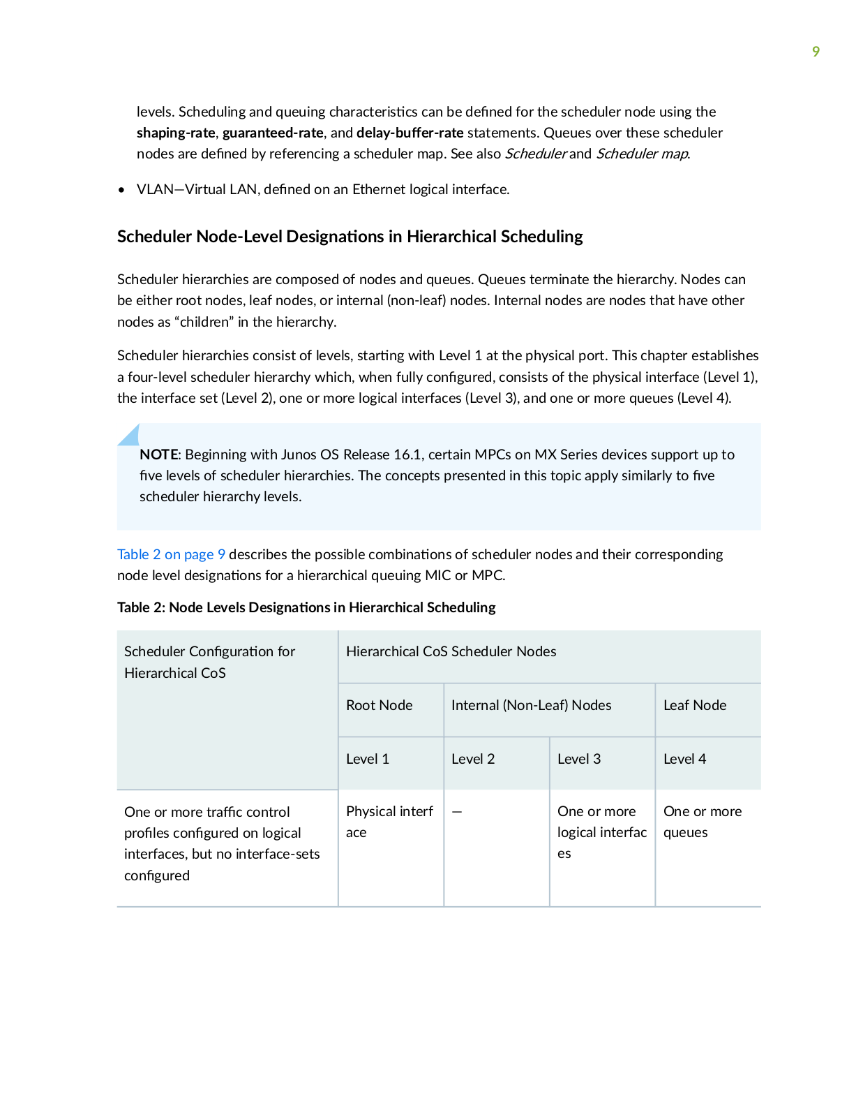
Scheduler hierarchies consist of levels, s r n with Level 1 at the physical port. This chapter establishes a four-level scheduler hierarchy which, when fully c n r consists of the physical interface (Level 1), the interface set (Level 2), one or more logical interfaces (Level 3), and one or more queues (Level 4).

NOTE: Beginning with Junos OS Release 16.1, certain MPCs on MX Series devices support up to v levels of scheduler hierarchies. The concepts presented in this topic apply similarly to v

scheduler hierarchy levels.

Table 2 on page 9 describes the possible c mb n

ns of scheduler nodes and their corresponding

node level

s

n


ns for a hierarchical queuing MIC or MPC.


Table 2: Node Levels

s n

ns in Hierarchical Scheduling


Scheduler C

n

r

n for


Hierarchical CoS Scheduler Nodes


Hierarchical CoS


Root Node


Internal (Non-Leaf) Nodes

Leaf Node


Level 1


Level 2


Level 3

Level 4


One or more

r

c control


Physical interf


One or more

One or more

r

s c

n

r

on logical


ace


logical interfac

queues

interfaces, but no interface-sets


es


c n

r


10

Table 2: Node Levels

s n

ns in Hierarchical Scheduling (C

n

n

)


Scheduler C n

r

n for


Hierarchical CoS Scheduler Nodes


Hierarchical CoS


Root Node

Internal (Non-Leaf) Nodes


Leaf Node


Level 1

Level 2


Level 3


Level 4


Interface-sets (c

c

ns of


Physical interf


Interface-set


One or more

logical interfaces) c n

r

but

ace


queues


no r

c c

n r

r

s


c n

r

on logical interfaces


Fully c

n

r

scheduler nodes

Physical interf

Interface-set


One or more


One or more


ace


logical interfac

queues


es


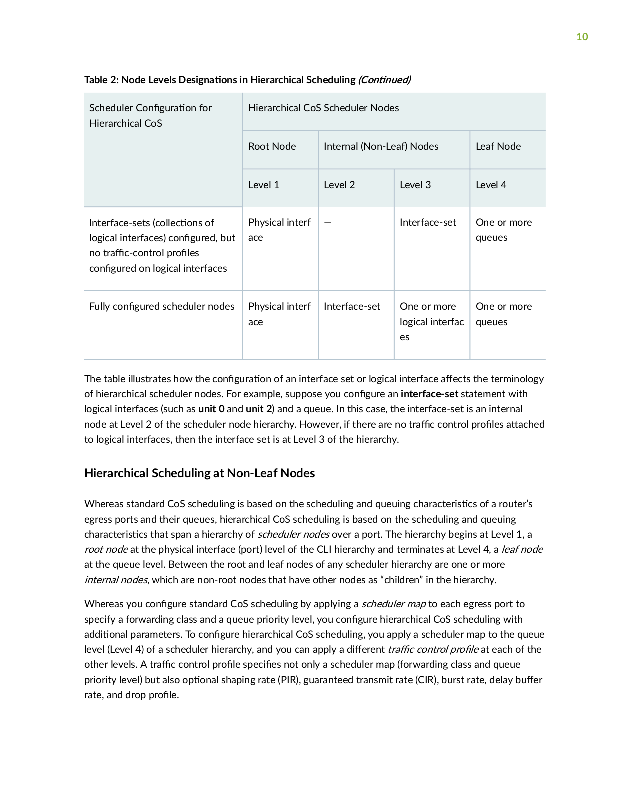
The table illustrates how the c

n

r n of an interface set or logical interface

c s the terminology

of hierarchical scheduler nodes. For example, suppose you c n

r

an interface-set statement with

logical interfaces (such as unit 0 and unit 2) and a queue. In this case, the interface-set is an internal


node at Level 2 of the scheduler node hierarchy. However, if there are no

r c control

r

s

c

to logical interfaces, then the interface set is at Level 3 of the hierarchy.


Hierarchical Scheduling at Non-Leaf Nodes

Whereas standard CoS scheduling is based on the scheduling and queuing c r c r s cs of a router’s egress ports and their queues, hierarchical CoS scheduling is based on the scheduling and queuing

c r c r s cs that span a hierarchy of scheduler nodes over a port. The hierarchy begins at Level 1, a root node at the physical interface (port) level of the CLI hierarchy and terminates at Level 4, a leaf node at the queue level. Between the root and leaf nodes of any scheduler hierarchy are one or more internal nodes, which are non-root nodes that have other nodes as “children” in the hierarchy.

Whereas you c n

r

standard CoS scheduling by applying a scheduler map to each egress port to


specify a forwarding class and a queue priority level, you c n

r hierarchical CoS scheduling with


n parameters. To c n


r hierarchical CoS scheduling, you apply a scheduler map to the queue

level (Level 4) of a scheduler hierarchy, and you can apply a

r n r c control r

at each of the

other levels. A r

c control

r

s c s not only a scheduler map (forwarding class and queue


priority level) but also

n

shaping rate (PIR), guaranteed transmit rate (CIR), burst rate, delay b

r

rate, and drop r


11

Release History Table

Release scr n

16.1

Beginning with Junos OS Release 16.1, certain MPCs on MX Series devices support up to v levels of


scheduler hierarchies.

Priority r

n in Hierarchical Scheduling

Priority r

n is performed for MX Series router output Interfaces on Enhanced Queuing DPCs,

MICs, and MPCs, and for M Series and T Series router output interfaces on IQ2E PICs. Priority

rn is useful for mixed r c environments when, for example, you want to make sure that the

voice r c of one customer does not s r due to the data r c of another customer. Nodes and queues are serviced in the order of their priority. The default priority of a queue is low, and you can

explicitly c

n

r a queue priority by including the priority statement at the [edit class-of-service

schedulers scheduler-name] hierarchy level.

You cannot directly c n

r

the r

r

s of all hierarchical scheduling elements. The r r s of

internal nodes, for example, are determined as follows:

• The highest priority of an

c v child, that is, a child currently containing r c (Interface sets only

take the highest priority of their

c v

children.)

• Whether the node is above its c

n

r guaranteed rate (CIR) or not (this is only relevant if the

physical interface is in CIR mode).


Each queue has a c n

r

priority and a hardware priority. The usual mapping between the

c n

r

priority and the hardware priority is shown in Table 3 on page 11.

Table 3: Queue Priority


C n

r

Priority


Hardware Priority


Strict-high


0


High


0


Medium-high


1


12

Table 3: Queue Priority (C n

n

)


C n r Priority


Hardware Priority


Medium-low


1


Low


2


MPCs also have c n r b

CLI

r r s of excess-priority high, excess-priority medium-high,

excess-priority medium-low, and excess-priority low. These r r s only take

c

above the

guaranteed rate.


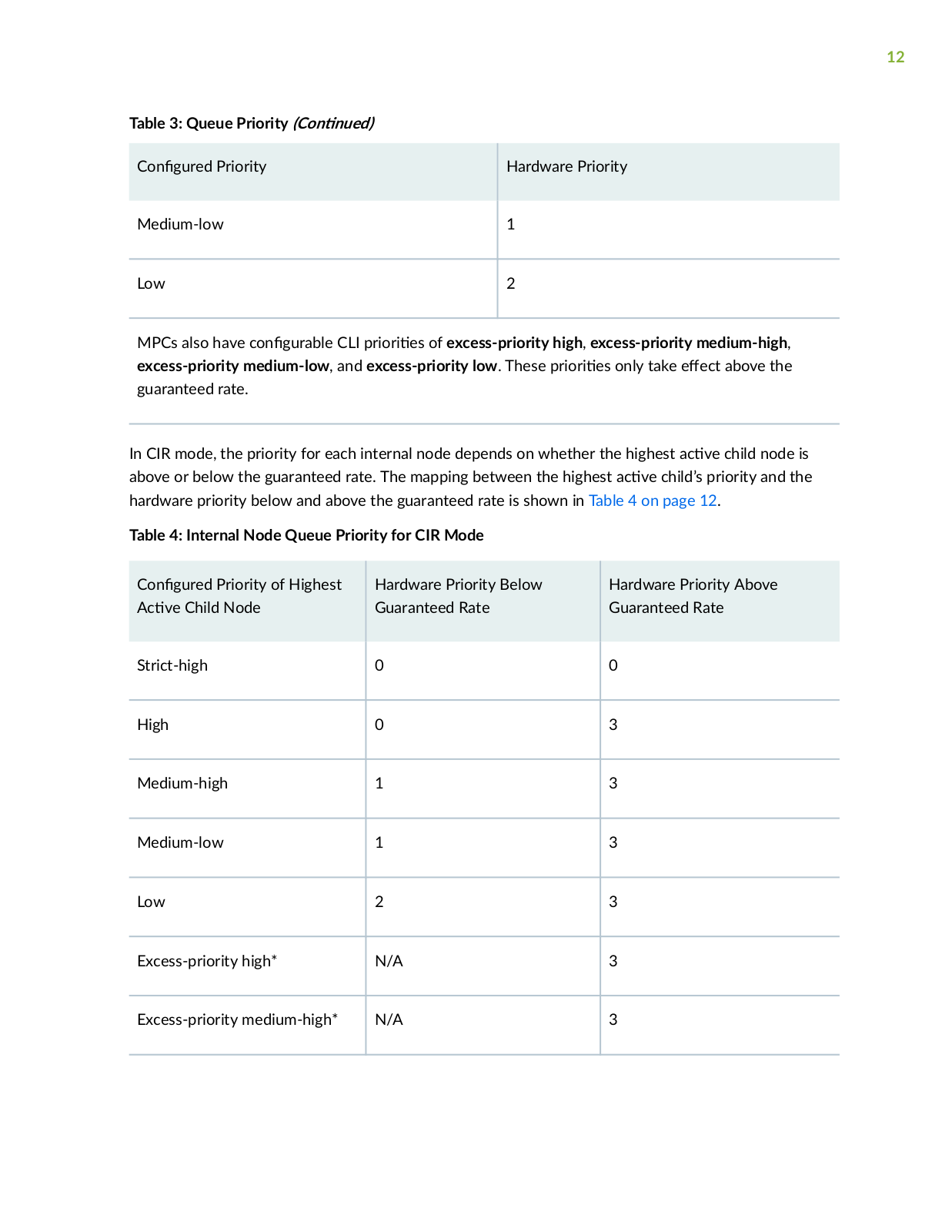
In CIR mode, the priority for each internal node depends on whether the highest

c v

child node is

above or below the guaranteed rate. The mapping between the highest c v child’s priority and the hardware priority below and above the guaranteed rate is shown in Table 4 on page 12.

Table 4: Internal Node Queue Priority for CIR Mode

C

n

r Priority of Highest

Hardware Priority Below

Hardware Priority Above

c

v

Child Node

Guaranteed Rate

Guaranteed Rate


Strict-high

0

0


High


0

3


Medium-high

1

3


Medium-low

1

3


Low


2

3


Excess-priority high*

N/A

3


Excess-priority medium-high*

N/A

3


13

Table 4: Internal Node Queue Priority for CIR Mode (C n n

)


C

n

r Priority of Highest

Hardware Priority Below


Hardware Priority Above

c

v

Child Node

Guaranteed Rate


Guaranteed Rate


Excess-priority medium-low*

N/A


4


Excess-priority low*

N/A


4


* MPCs only

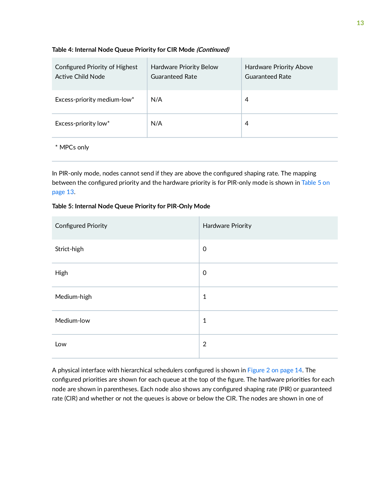
In PIR-only mode, nodes cannot send if they are above the c

n

r shaping rate. The mapping

between the c n

r priority and the hardware priority is for PIR-only mode is shown in Table 5 on

page 13.


Table 5: Internal Node Queue Priority for PIR-Only Mode


C n

r

Priority

Hardware Priority


Strict-high


0


High


0


Medium-high


1


Medium-low


1


Low


2


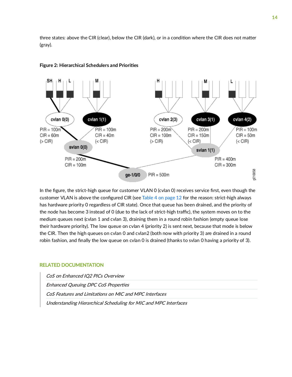
A physical interface with hierarchical schedulers c n

r is shown in Figure 2 on page 14. The

c n

r

r r

s are shown for each queue at the top of the

r The hardware r r s for each

node are shown in parentheses. Each node also shows any c

n

r shaping rate (PIR) or guaranteed

rate (CIR) and whether or not the queues is above or below the CIR. The nodes are shown in one of

Juniper Hierarchical Class User Manual

14

three states: above the CIR (clear), below the CIR (dark), or in a c n

n where the CIR does not m

r

(gray).


Figure 2: Hierarchical Schedulers and r r s


In the r the strict-high queue for customer VLAN 0 (cvlan 0) receives service rs even though the customer VLAN is above the c n r CIR (see Table 4 on page 12 for the reason: strict-high always has hardware priority 0 regardless of CIR state). Once that queue has been drained, and the priority of the node has become 3 instead of 0 (due to the lack of strict-high r c) the system moves on to the medium queues next (cvlan 1 and cvlan 3), draining them in a round robin fashion (empty queue lose their hardware priority). The low queue on cvlan 4 (priority 2) is sent next, because that mode is below the CIR. Then the high queues on cvlan 0 and cvlan2 (both now with priority 3) are drained in a round robin fashion, and n y the low queue on cvlan 0 is drained (thanks to svlan 0 having a priority of 3).

RELATED DOCUMENTATION

CoS on Enhanced IQ2 PICs Overview

Enhanced Queuing DPC CoS r r s

CoS Features and m ns on MIC and MPC Interfaces

Understanding Hierarchical Scheduling for MIC and MPC Interfaces

15

C n r n Hierarchical Schedulers for CoS

In metro Ethernet environments, a virtual LAN (VLAN) typically corresponds to a customer premises

equipment (CPE) device and the VLANs are n

by an inner VLAN tag on Ethernet frames (called

the customer VLAN, or C-VLAN, tag). A set of VLANs can be grouped at the DSL access m

x r

(DSLAM) and n

by using the same outer VLAN tag (called the service VLAN, or S-VLAN, tag).

The service VLANs are typically gathered at the Broadband Remote Access Server (B-RAS)


level.Hierarchical schedulers let you provide shaping and scheduling at the service VLAN level as well as other levels, such as the physical interface. In other words, you can group a set of logical interfaces and then apply scheduling and shaping parameters to the logical interface set as well as to other levels.

On Juniper Networks MX Series 5G Universal R

n

rms and systems with Enhanced IQ2 (IQ2E)

PICs, you can apply CoS shaping and scheduling at one of four

r n levels, including the VLAN set

level. You can only use this c n r n on MX Series routers or IQ2E PICs. Beginning with Junos OS Release 16.1, certain MPCs support up to v levels of scheduler hierarchies.

The supported scheduler hierarchy is as follows:

The physical interface (level 1)

The service VLAN (level 2 is unique to MX Series routers)

The logical interface or customer VLAN (level 3)

The queue (level 4)

Users can specify a r

c control

r

(

r c c n r

r

that can specify a shaping rate, a

guaranteed rate, and a scheduler map with transmit rate and b

r delay. The scheduler map contains

the mapping of queues (forwarding classes) to their r s c v

schedulers (schedulers

n the

r

r

s for the queue). Queue

r

r

s can specify a transmit rate and b

r management

parameters such as b

r size and drop

r


To c

n

r CoS hierarchical scheduling, you must enable hierarchical scheduling by including the

hierarchical-scheduler statement at the physical interface.


RELATED DOCUMENTATION

Understanding Hierarchical Scheduling

Understanding Hierarchical Scheduling for MIC and MPC Interfaces

CoS on Enhanced IQ2 PICs Overview

Understanding Hierarchical CoS for Subscriber Interfaces | 87

Loading...
+ 961 hidden pages