

Page 1

Juniper Networks
G10 CMTS
Getting Started
Juniper Networks, Inc.
1194 North Mathilda Avenue
Sunnyvale, CA 94089
USA
408-745-2000
www.juniper.net
Part Number: 530-008005-01, Revision 1
Page 2

•
•
Copyright © 2002, Juniper Networks, Inc. All rights reserved. Juniper Networks is registered in the U.S. Patent and Trademark Office and in other countries
•
as a trademark of Juniper Networks, Inc. Broadband Cable Processor, G10, Internet Processor, JUNOS, JUNOScript, M5, M10, M20, M40, M40e, M-series,
M160, ServiceGuard, T640, and T-series are trademarks of Juniper Networks, Inc. All other trademarks, service marks, registered trademarks, or registered
•
service marks are the property of their respective owners. All specifications are subject to change without notice.
•
•
Products made or sold by Juniper Networks (including the M5, M10, M20, M40, M40e, and M160 routers, T640 routing node, and the JUNOS software) or
•
components thereof might be covered by one or more of the following patents that are owned by or licensed to Juniper Networks: U.S. Patent Nos.
5,473,599, 5,905,725, and 5909,440.
•
•
Juniper Networks G10 CMTS Getting Started
•
Copyright © 2002, Juniper Networks, Inc.
All rights reserved. Printed in USA.
•
•
Writer: Jerry Isaac
•
Illustrations: Paul Gilman
•
Covers and template design: Edmonds Design
•
Revision History
•
17 June 2002—First Edition.
•
•
Juniper Networks assumes no responsibility for any inaccuracies in this document. Juniper Networks reserves the right to change, modify, transfer, or
otherwise revise this publication without notice.
•
•
The DOCSIS Module performs encryption that is subject to U.S. Customs and Export regulations. A DOCSIS Module shall not be exported, sold or transferred
•
to a country outside the USA and Canada without an appropriate export license from the U.S. Government. The specific Regulations governing exports of
encryption products are set forth in the Export Administration Regulations, 15 C.F.R. (Code of Federal Regulations), Parts 730-774.
•
•
•
•
•
•
•
•
•
•
•
•
•
•
•
•
•
•
•
•
•
•
•
•
•
•
•
•
•
•
•
•
•
•
•
•
•
ii
Page 3

Table of Contents
About This Manual
Purpose .................................................................................................................ix
Organization..........................................................................................................ix
Document Conventions ..........................................................................................x
Notes, Cautions, and Warnings........................................................................x
G10 CMTS Document Set.......................................................................................xi
Chapter 1
Chapter 2
Chapter 3
G10 CMTS Hardware Overview ........................................................................1
G10 CMTS Installation ..........................................................................................9
Tools and Equipment Required for Installation.......................................................9
Installation Preparation.........................................................................................10
Notices..................................................................................................................11
Rack Mounting......................................................................................................12
Installing Power Supplies ......................................................................................14
Installing a Front-Loaded Module..........................................................................17
Installing a Rear-Loaded Module ...........................................................................19
Cabling an HFC Connector Module .......................................................................21
Cabling a Chassis Control Module.........................................................................23
Cabling a NIC Module ...........................................................................................25
Cabling a NIC Access Module................................................................................28
Attaching a PC to the Chassis Control Module.......................................................31
Connecting to Power Sources ...............................................................................32
AC Power.......................................................................................................32
DC Power ......................................................................................................33
G10 CMTS Configuration ...................................................................................35
Powering On the G10 CMTS .................................................................................35
Powering On and Configuring the PC ...................................................................39
Logging In and Out of the G10 CMTS.............................................................39
Configuring the G10 CMTS....................................................................................40
Cable Interface Assignment...........................................................................40
Creating Usernames and Passwords..............................................................42
•
•
•
•
•
•
•
•
•
•
•
•
•
•
•
•
•
•
•
•
•
•
•
•
•
•
•
•
•
•
•
•
•
•
•
•
•
•
•
•
•
•
•
•
•
•
•
•
Table of Contents
iii
Page 4

•
•
•
•
•
•
•
•
•
•
•
•
•
•
•
•
•
•
•
•
•
•
•
•
•
•
•
•
•
•
•
•
•
•
•
•
•
•
•
•
•
•
•
•
•
•
•
•
•
•
•
•
•
•
•
•
•
•
Index
Index ..............................................................................................................................47
Configuring Miscellaneous Parameters..........................................................42
Viewing and Saving Running Configuration...................................................42
Configuring Downstream Channel Parameters..............................................43
Configuring Upstream Channel Parameters...................................................44
Configuring Fast Ethernet Interfaces .............................................................45
Configuring Gigabit Ethernet Interfaces.........................................................45
Configuring a Management Interface.............................................................46
Juniper Networks G10 CMTS Getting Started
iv
Page 5

List of Figures
List of Figures
Figure 1: Front View of Fully-Configured Chassis ................................................2
Figure 2: Front View of Partially-Configured Chassis............................................3
Figure 3: Rear View of Fully-Configured Chassis..................................................4
Figure 4: Rear View of Partially-Configured Chassis.............................................5
Figure 5: Top View of Chassis Midplane ..............................................................6
Figure 6: Bottom of Chassis...............................................................................13
Figure 7: Front and Rear Views of Midplane......................................................16
Figure 8: Power Supply Installation ...................................................................17
Figure 9: Front-Loaded Module Installation .......................................................19
Figure 10: Rear-Loaded Module Installation ........................................................20
Figure 11: Example of Allocation of Multiple Channels Per Port ..........................21
Figure 12: HFC Connector Module Rear Panel.....................................................22
Figure 13: Chassis Control Module and CCM Access Module Front Panels...........24
Figure 14: NIC Module and NIC Access Module Panels ........................................26
Figure 15: NIC Module Cabling – Front View.......................................................27
Figure 16: NIC Access Module Cable Connections ...............................................30
Figure 17: AC Power Cord and Retainer Clip .......................................................33
Figure 18: DC Power Transition Module ..............................................................34
Figure 19: DOCSIS Module and Chassis Control Module Front Panels..................37
Figure 20: NIC Module and NIC Access Module Panels ........................................38
•
•
•
•
•
•
•
•
•
•
•
•
•
•
•
•
•
•
•
•
•
•
•
•
•
•
•
•
•
•
•
•
•
•
•
•
•
•
•
•
•
•
•
•
•
•
•
•
List of Figures
v
Page 6

•
•
•
•
•
•
•
•
•
•
•
•
•
•
•
•
•
•
•
•
•
•
•
•
•
•
•
•
•
•
•
•
•
•
•
•
•
•
•
•
•
•
•
•
•
•
•
•
•
•
•
•
•
•
•
•
•
•
List of Figures
Juniper Networks G10 CMTS Getting Started
vi
Page 7

List of Tables
List of Tables
Table 1: Power Supply Guideline......................................................................18
Table 2: NIC Access Module Wiring Plan ..........................................................31
Table 3: Downstream Channel Assignment......................................................41
Table 4: Upstream Channel Assignment (8-Channel DOCSIS Module)..............41
Table 5: Upstream Channel Assignment (16-Channel DOCSIS Module) ............41
Table 6: Downstream Channel Parameter Ranges............................................43
Table 7: Upstream Channel Parameter Ranges.................................................44
•
•
•
•
•
•
•
•
•
•
•
•
•
•
•
•
•
•
•
•
•
•
•
•
•
•
•
•
•
•
•
•
•
•
•
•
•
•
•
•
•
•
•
•
•
•
•
•
List of Tables
vii
Page 8

•
•
•
•
•
•
•
•
•
•
•
•
•
•
•
•
•
•
•
•
•
•
•
•
•
•
•
•
•
•
•
•
•
•
•
•
•
•
•
•
•
•
•
•
•
•
•
•
•
•
•
•
•
•
•
•
•
•
List of Tables
Juniper Networks G10 CMTS Getting Started
viii
Page 9

About This Manual
This section describes important information about the design of this document.
Purpose
The purpose of the Juniper Networks G10 CMTS Getting Started manual is to provide
experienced personnel the procedures required to properly install and configure the G10
Cable Modem Termination System (CMTS).
If you do not have experience with the installation and configuration of CMTS equipment in
cable headends, or if you need more details regarding the installation, configuration, or
upgrading of the G10 CMTS, then it is recommended that you follow the procedures
provided in the companion manual Juniper Networks G10 CMTS Installation and Configuration
for more detailed information.
Additional instructions and details regarding the subsequent and on-going operation of the
CMTS can be found in the documents listed in “G10 CMTS Document Set” on page xi.
Organization
Juniper Networks G10 CMTS Getting Started is organized as follows:
Chapter 1, “G10 CMTS Hardware Overview” – Provides a hardware overview of the G10
Chapter 2, “G10 CMTS Installation” – Provides the procedures that must be followed to
Chapter 3, “G10 CMTS Configuration” – Describes the configuration procedure for the
CMTS.
install the G10 CMTS in the headend.
G10 CMTS.
•
•
•
•
•
•
•
•
•
•
•
•
•
•
•
•
•
•
•
•
•
•
•
•
•
•
•
•
•
•
•
•
•
•
•
•
•
•
•
•
•
•
•
•
•
•
•
•
About This Manual
ix
Page 10
Document Conventions
•
Document Conventions
•
•
The following document conventions are used in this manual:
•
•
•
•
General
Conventions
•
Italic font Denotes a) emphasis, b) first use of a new term, or c) a document title.
Screen Name font Denotes a) the on-screen name of a window, dialog box or field, or b) keys on a
•
•
•
•
Software
Conventions
•
Computer font Font denotes code or messages displayed on-screen.
Computer Bold font Font denotes literal commands and parameters that you enter exactly as shown.
•
•
<Computer Italic> font Font denotes parameter values that require a user-defined input.
•
•
•
•
•
•
•
•
•
•
[parameter] Square brackets denote optional parameters.
{parameter} Braces denote required parameters.
| Vertical bars separate parameters in a group from which you must choose only one.
↵ Return symbol indicates pressing the Enter key at the end of a command line.
•
•
•
Notes, Cautions, and Warnings
•
•
•
•
•
•
•
•
•
•
•
•
•
•
•
•
•
•
•
•
•
•
•
•
•
•
•
•
•
•
keyboard.
The value strings are enclosed in angle brackets <...>.
A note indicates information that might be helpful in a
particular situation, or information that might otherwise
be overlooked.
A caution indicates a situation that requires careful
attention. Failure to observe a cautionary note could result
in injury or discomfort to yourself, or serious damage to
the product.
A warning is intended to alert the user of the presence of
uninsulated dangerous voltage within the product’s
enclosure that may present a risk of electric shock.
Juniper Networks G10 CMTS Getting Started
x
Page 11
G10 CMTS Document Set
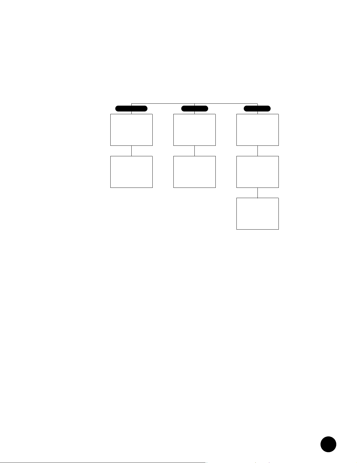
G10 CMTS Document Set
PREPARATION
Pre-Installation
530-008003-01
Installation and
Configuration
Guide
OPERATION
Getting Started
Operation and
Maintenance
REFERENCE
Functional
Description
530-008007-01530-008005-01
SNMP and
Enterprise MIB
Specification
530-008008-01530-008004-01530-008002-01
CLI Reference
530-008006-01
•
•
•
•
•
•
•
•
•
•
•
•
•
•
•
•
•
•
•
•
•
•
•
•
•
•
•
•
•
•
•
•
•
•
•
•
•
•
•
•
•
•
•
•
•
•
•
•
•
•
•
•
•
•
•
•
•
•
About This Manual
xi
Page 12

G10 CMTS Document Set
•
•
•
•
•
•
•
•
•
•
•
•
•
•
•
•
•
•
•
•
•
•
•
•
•
•
•
•
•
•
•
•
•
•
•
•
•
•
•
•
•
•
•
•
•
•
•
•
•
•
•
•
•
•
•
•
•
•
Juniper Networks G10 CMTS Getting Started
xii
Page 13

Chapter 1
G10 CMTS Hardware Overview
This chapter provides an overview of the modules and various hardware components of the
G10 Cable Modem Termination System (CMTS), and where they reside within the chassis.
This overview presents material that is specific to the installation and configuration of the
G10 CMTS. For more details and specifications regarding these assemblies, refer to the
Juniper Networks G10 CMTS Functional Description.
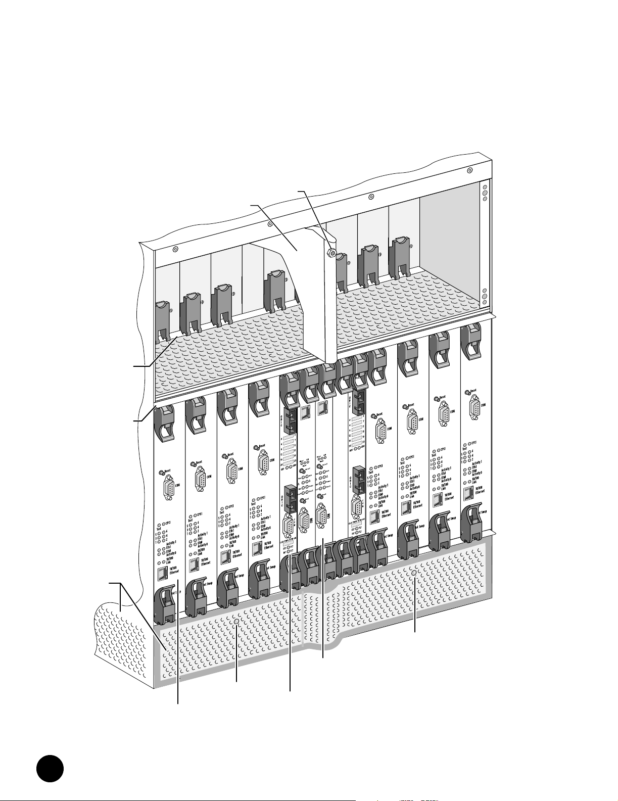
Figure 1 on page 2 illustrates a front view of a fully-configured chassis. Figure 2 on page 3
illustrates a front view of a partially-configured chassis in which DOCSIS Modules, a Chassis
Control Module (CCM), a Network Interface Card (NIC) Module, power supplies, air
management modules, and power supply filler panels have been removed. Figure 3 on
page 4 illustrates a rear view of a fully-configured chassis. Figure 4 on page 5 illustrates the
rear view of the partially-configured chassis in which HFC Connector Modules, a CCM Access
Module, a NIC Access Module, and air management panels have been removed. Figure 5 on
page 6 provides a top view of the chassis midplane showing the slot enumeration and
location of each module.
All of the features of the chassis that are cited in these figures will be referenced in one or
more procedures described in this document.
•
•
•
•
•
•
•
•
•
•
•
•
•
•
•
•
•
•
•
•
•
•
•
•
•
•
•
•
•
•
•
•
•
•
•
•
•
•
•
•
•
•
•
•
•
•
•
•
G10 CMTS Hardware Overview
1
Page 14
•
Figure 1: Front View of Fully-Configured Chassis
•
•
•
•
•
•
•
•
•
•
•
•
Po
•
Powe
r
e
w
Fault
Po
r
Fault
•
•
•
•
•
•
•
•
•
•
Power
Supply
Ejector
Rail
•
•
•
•
•
Module
Ejector
Rail
•
•
•
•
•
•
•
•
•
•
•
•
•
•
•
Air
Intake
•
•
•
•
•
•
•
•
•
•
•
•
DOCSIS
Module
•
•
Cable
Guide
er
w
ult
Fa
Front Fan
Tray LED
ESD
Strap
Jack
Power
Fault
Module
NIC
er
Pow
lt
u
Fa
Eth0
2
1
Chassis
Control
Module
er
Pow
lt
u
er
Pow
er
Pow
Fa
0
h
t
E
2
1
Fa
lt
u
Fa
lt
u
Front Fan
Tray L E D
Juniper Networks G10 CMTS Getting Started
2
Page 15
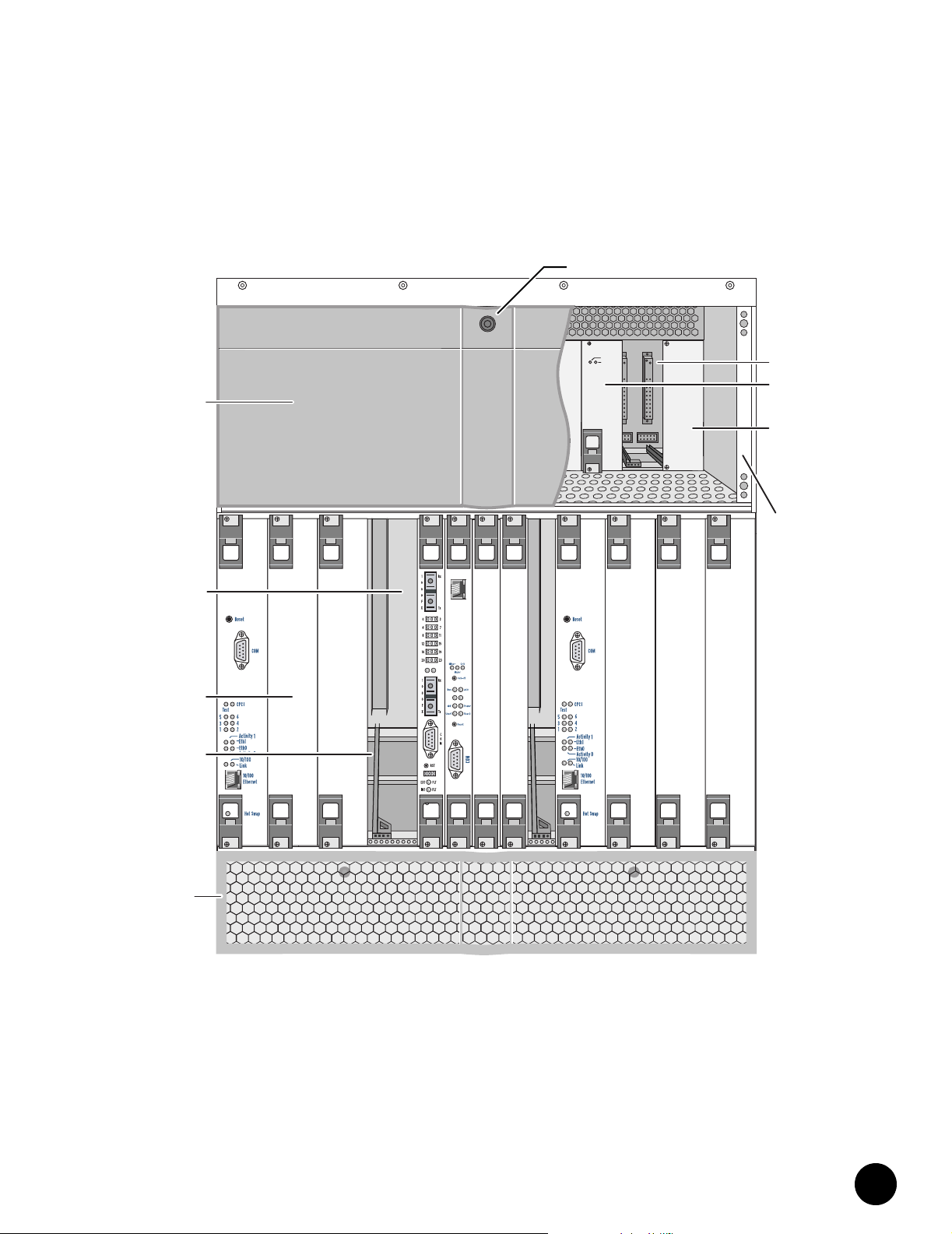
Figure 2: Front View of Partially-Configured Chassis
Power
Fault
Power
Power
Power
Power
Fault
Fault
Power
Fault
Fault
Supply
Faceplate
Midplane
Air
Management
Module
Card
Guide
Air
Intake
Faceplate
•
•
•
ESD
Strap
Jack
•
•
•
•
•
•
Power
Power
Fault
Power
Power
Fault
Fault
Power
Fault
Supply
Bay
Power
Supply
Power
Supply
Filler
Panel
•
•
•
•
•
•
•
•
•
•
•
Power
Supply
Faceplate
Clip
•
•
•
•
•
•
•
•
•
•
•
•
•
•
•
•
•
•
•
•
•
•
•
•
•
•
•
•
•
•
•
•
•
•
•
•
•
•
G10 CMTS Hardware Overview
3
Page 16
•
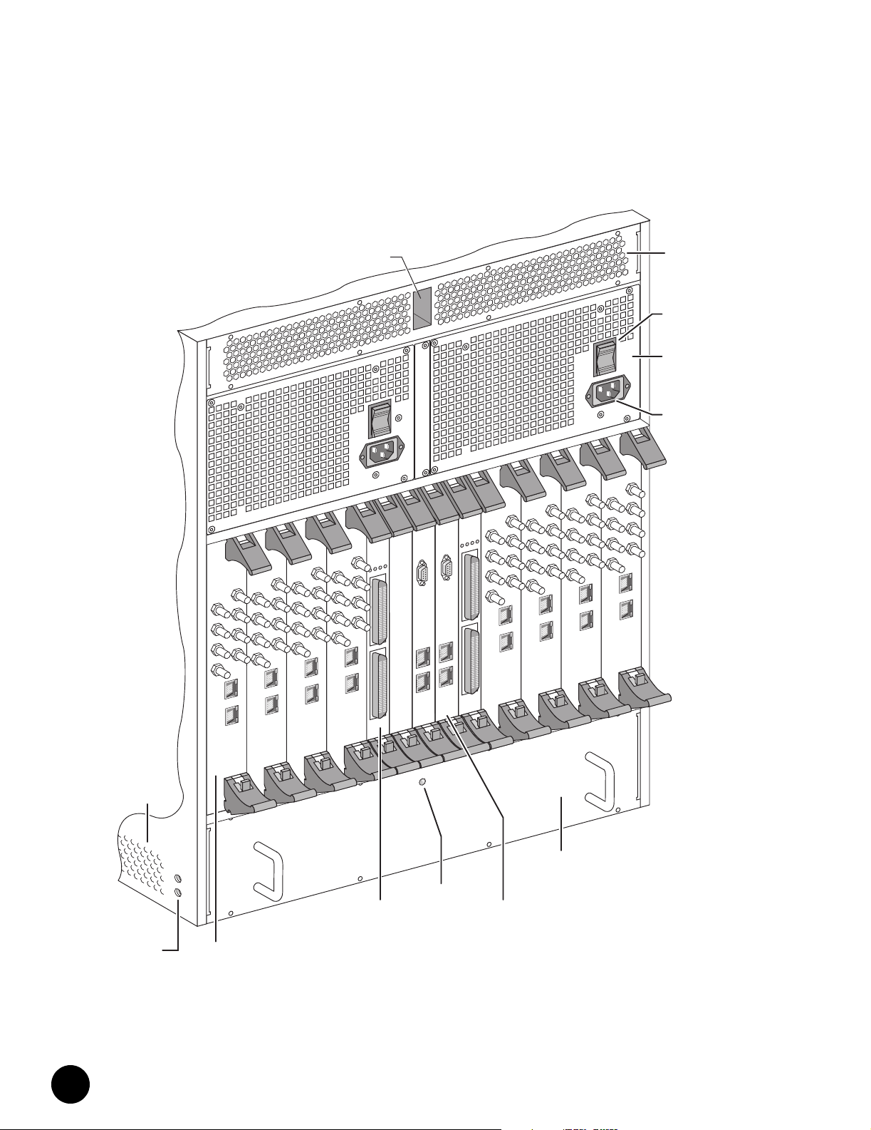
Figure 3: Rear View of Fully-Configured Chassis
•
•
•
•
•
•
•
•
•
•
•
•
•
•
•
•
•
•
•
•
•
•
•
•
•
•
•
•
•
•
•
•
S 0
D
0
US
DS 1
1
US 1
S 2
D
2
2
US
DS 3
US 3
•
•
•
•
Eth0
Eth1
0
S
D
US 0
US 0
S 1
D
US 1
1
US
S 2
D
US
2
US
S 3
D
US 3
US 3
Eth0
Eth0
Eth1
Eth1
•
•
•
•
•
Air
Intake
•
•
•
•
•
•
•
•
•
•
•
•
Chassis
Ground
Nuts
HFC
Connector
Module
•
•
•
•
2
S 0
D
DS 1
S 2
D
DS 3
Cable
Channel
DS 0
0
US
S 1
D
US 1
S 2
D
US 2
S 3
D
US 3
Eth0
Eth1
Access
Module
OPERATIONAL
POWER
1
2
NIC
INT FAULT
EXT FAULT
C
O
C
M
O
M
Eth0
Eth0
Eth1
Eth1
Rear Fan
Tray LED
OPERATIONAL
INT FAULT
POWER
1
2
EXT FAULT
0
US
1
US
US 2
US 3
Eth0
Eth1
CCM
Access
Module
S 0
D
S 1
D
S 2
D
DS 3
S 0
D
US 0
DS 1
1
US
S 2
D
2
US
DS 3
US 3
Eth0
Eth1
Rear Fan
Tray
Air
Exhaust
AC Power
Switch
AC Power
Transition
Module
AC Power
Receptacle
DS 0
S 0
D
0
US
S 1
US 0
US 1
2
US
US 3
Eth0
Eth1
D
1
S
D
US 1
2
S
D
DS 2
US 2
S 3
D
S 3
D
US 3
Eth0
Eth1
Juniper Networks G10 CMTS Getting Started
4
Page 17
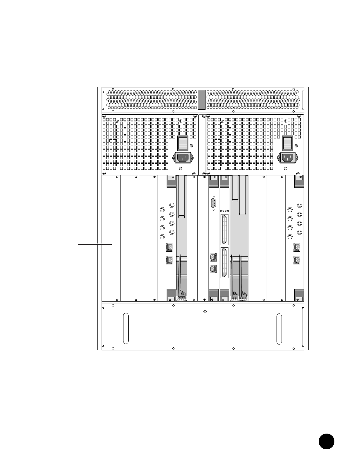
Figure 4: Rear View of Partially-Configured Chassis
Air
Management
Panel
•
•
•
•
•
•
•
•
•
•
•
•
•
•
•
•
•
•
•
•
OPERATIONAL
EXT FAULT
INT FAULT
DS 0
US 0
DS 1
US 1
DS 2
US 2
DS 3
US 3
C
POWER
O
M
1
DS 0
US 0
DS 1
US 1
DS 2
US 2
DS 3
US 3
•
•
•
•
•
•
•
•
Eth0
Eth1
Eth0
2
Eth1
Eth0
Eth1
•
•
•
•
•
•
•
•
•
•
•
•
•
•
•
•
•
•
•
•
•
•
•
•
•
•
•
•
•
•
G10 CMTS Hardware Overview
5
Page 18
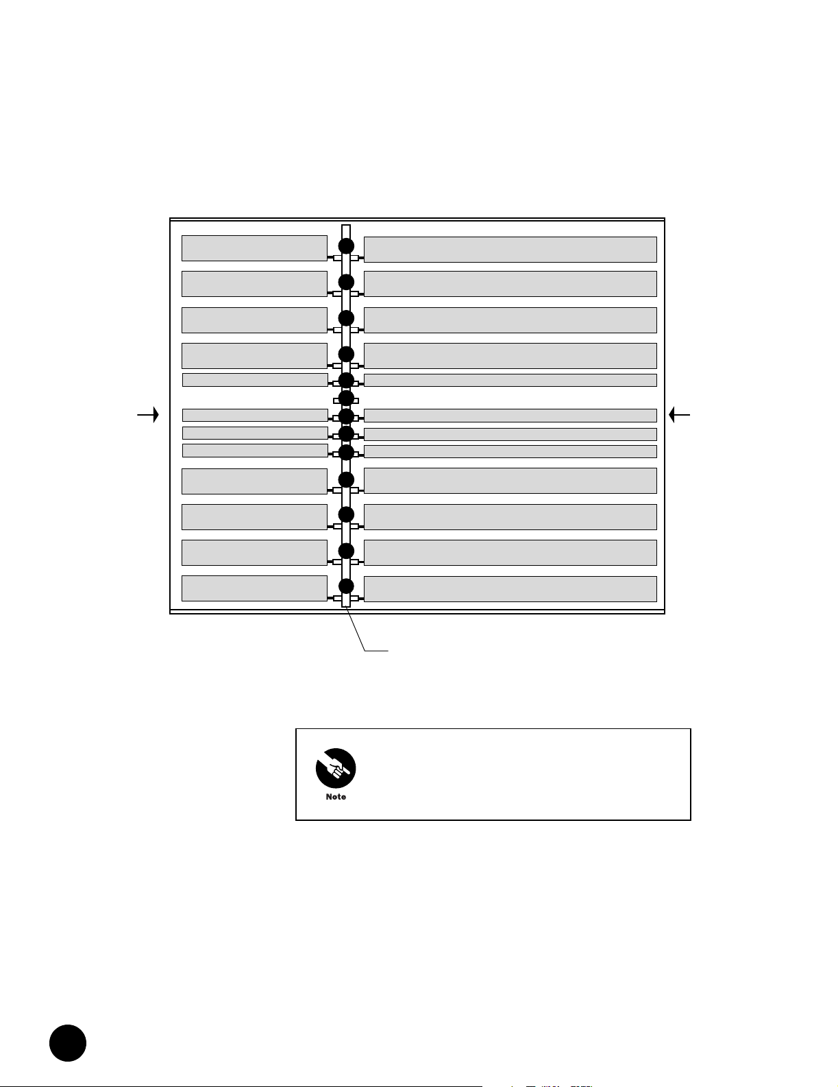
•
Figure 5: Top View of Chassis Midplane
•
•
•
•
•
•
•
HFC Connector Module
•
•
HFC Connector Module
•
•
HFC Connector Module
•
•
•
•
HFC Connector Module
NIC Access Module
•
•
•
Rear
•
•
CCM Access Module
CCM Access Module
NIC Access Module
•
•
HFC Connector Module
•
•
HFC Connector Module
•
•
•
HFC Connector Module
•
•
HFC Connector Module
•
•
•
•
•
•
•
•
•
•
•
•
•
•
•
•
•
•
•
•
•
•
•
•
•
•
•
•
13
12
11
10
9
8
7
6
5
4
3
2
1
Midplane
with logical slot numbers
DOCSIS Module
DOCSIS Module
DOCSIS Module
DOCSIS Module
NIC Module
Front
Chassis Control Module
Chassis Control Module
NIC Module
DOCSIS Module
DOCSIS Module
DOCSIS Module
DOCSIS Module
Module slots 1 through 6 reside in Domain A. Module slots
7, and 9 through 13 reside in Domain B.
Following is a brief explanation of each feature referenced in Figure 1 through Figure 4:
DOCSIS Module—Module that contains the Broadband Cable Processor ASIC and resides
between the Network Side Interface (NSI) and the Hybrid Fiber/Coax (HFC) interface
NIC Module—Module that provides the Gigabit Ethernet interface and the Fast Ethernet
switching functions for the network side interface
Chassis Control Module—Module that performs management and monitoring functions
Juniper Networks G10 CMTS Getting Started
6
Page 19

Module Ejector Rail—Rail into which a module’s ejector tabs mate when a module is
installed into a slot
ESD Strap Jack—Location in front of chassis where ESD ground strap can be plugged
Chassis Ground Nuts—Location where the earth ground connection to the chassis is
made
Air Intake—Slotted openings along the front (removable) and sides of the chassis where
air is drawn into the chassis for cooling the installed modules and power supplies
Air Intake Faceplate—Slotted removable panel that covers up the two front fan trays
Air Intake Faceplate Clip—Retainer clip used to mount the air intake faceplate
Front Fan Tray—Fan assembly that forces air upward through the front of the chassis
Front Fan Tray LED—LED that represents the status of the front fan tray
Power Supply Ejector Rail—Rail into which the power supply ejector tabs mate when a
power supply is installed into a bay
Midplane—Passive electrical interconnecting device for all modules in the chassis
Air Management Module—Module that is installed into an unused module slot to redirect
the air flow through the chassis
Card Guide—Used to align a module or power supply while it is being inserted into its
slot or bay, respectively
Power Supply—Converts AC or DC power supplied through the power transition modules
into the DC voltages required by the modules
Power Supply Faceplate—Panel that runs along the top of the chassis that covers up the
power supplies
Power Supply Faceplate Clip—Retainer clip used to mount the power supply faceplate
Power Supply Bay—Chassis bay in which a single hot-swappable power supply is
inserted
Power Supply Filler Panel—Panel covering an empty power supply bay
Cable Channel—Channel that runs through the top of the chassis that is used to route
the network cables from the rear of the chassis to the front of the chassis
Cable Guide—Guide in the front of the chassis used to route the network cables between
the cable channel and the lower opening in the power supply faceplate
HFC Connector Module—Module that functions as the DOCSIS Module’s physical access
to both the NSI and the HFC interfaces on the rear of the chassis
NIC Access Module—Module that provides the network connections between the NIC
Modules and the HFC Connector Modules
CCM Access Module—Module that provides Ethernet and serial connector access to the
Chassis Control Module from the rear of the chassis
•
•
•
•
•
•
•
•
•
•
•
•
•
•
•
•
•
•
•
•
•
•
•
•
•
•
•
•
•
•
•
•
•
•
•
•
•
•
•
•
•
•
•
•
•
•
•
•
•
•
•
•
•
•
•
•
•
•
G10 CMTS Hardware Overview
7
Page 20

•
•
•
•
•
•
•
•
•
•
•
•
•
•
•
•
•
•
•
•
•
•
•
•
•
•
•
•
•
•
•
•
•
•
•
•
•
•
•
•
•
•
•
•
•
•
•
•
•
•
•
•
•
•
•
•
•
•
Rear Fan Tray—Fan assembly that forces air upward through the rear of the chassis
Rear Fan Tray LED—LED that represents the status of the rear fan tray
Air Management Panel—Panel that is installed over an unused module slot to redirect
the air flow through the chassis
Air Exhaust—Panel along the top and rear of the chassis where air is exhausted out of
the chassis for cooling purposes
AC Power Transition Module—Rear module that distributes the externally-supplied AC
power to the midplane
AC Power Receptacle—AC power cord receptacle on AC Power Transition Module
AC Power Switch—AC power ON/OFF switch that resides on the AC Power Transition
Module
DC Power Transition Module—Rear module that distributes the externally-supplied DC
power to the midplane
DC Power Receptacle—DC power cord terminal block on DC Power Transition Module
Juniper Networks G10 CMTS Getting Started
8
Page 21

Chapter 2
G10 CMTS Installation
This chapter describes the installation procedure for the G10 CMTS. It is recommended that
the entire installation process in this chapter be read prior to performing the actual G10
CMTS installation.
Tools and Equipment Required for Installation
The following tools are needed to install power supplies and modules, and to rack mount the
G10 CMTS chassis:
M2.5 Phillips torque screwdriver
M2.5 flathead torque screwdriver
M3 Phillips torque screwdriver
M5 Phillips torque screwdriver
#10 Phillips torque screwdriver
#10 flathead torque screwdriver
#12 Phillips torque screwdriver
7/16 in. torque wrench
22-10 AWG crimper/cutter/stripper
In addition, the following supplies may be required:
RF cables and adapters
Ethernet cables with RJ-45 connectors
The following equipment is required to configure the G10 CMTS and verify that the RF
system has been setup properly:
PC with asynchronous terminal emulation
RF spectrum analyzer
RF power meter
•
•
•
•
•
•
•
•
•
•
•
•
•
•
•
•
•
•
•
•
•
•
•
•
•
•
•
•
•
•
•
•
•
•
•
•
•
•
•
•
•
•
•
•
•
•
•
•
G10 CMTS Installation
9
Page 22

Installation Preparation
•
Installation Preparation
•
•
•
•
•
•
•
•
•
•
•
•
•
•
•
•
•
•
•
•
•
•
•
•
•
•
•
•
•
•
•
•
•
•
•
•
•
•
•
•
•
•
•
•
•
•
•
•
•
•
•
•
•
•
•
•
•
1. Ensure that the procedures and the checklist provided in the Juniper Networks G10 CMTS
Pre-Installation Guide have been successfully completed and approved by the user and
Juniper Networks field engineers.
2. Ensure that all safety precautions and procedures described in the Juniper Networks G10
CMTS Installation and Configuration manual have been followed prior to performing the
procedures presented in this chapter.
High levels of electrical energy are distributed across the
system midplane. Be careful not to contact the midplane
connectors, or any component connected to the midplane,
with any metallic object while hot-swapping or servicing
components installed in the system.
3. Verify that the contents of the shipping cartons and accessory kits are identical to the
contents listed on their corresponding packing lists.
4. Install the power supply faceplate included in the shipment by aligning its four ball studs
with the four power supply faceplate clips and pressing the faceplate towards the
chassis until it snaps into place.
The power supply faceplate must always be installed prior
to powering on the G10 CMTS to ensure that proper air
ventilation occurs throughout the chassis.
5. Install the air intake faceplate included in the shipment by aligning its four ball studs
with the four air intake faceplate clips and pressing the faceplate towards the chassis
until it snaps into place.
Juniper Networks G10 CMTS Getting Started
10
Page 23

Notices
Notices
This equipment is intended only for installation in a
restricted access location within a building.
This equipment is intended for indoor use only.
This equipment does not have a direct copper
connection to the outside plant.
Removal of power supplies or cards will result in
access to hazardous energy.
Each power cord must be connected to an
independent branch circuit.
Product connected to two power sources. Disconnect
both power sources before servicing.
Risk of explosion if battery is replaced by an incorrect
type. Dispose of used batteries according to the
instructions.
This is a Class A product. In a domestic environment this
product may cause radio interference in which case the
user may be required to take adequate measures.
This device complies with Part 15 of the FCC Rules.
Operation is subject to the following two conditions:
(1) This device may not cause harmful interference, and
(2) this device must accept any interference received,
including interference that may cause undesired operation.
•
•
•
•
•
•
•
•
•
•
•
•
•
•
•
•
•
•
•
•
•
•
•
•
•
•
•
•
•
•
•
•
•
•
•
•
•
•
•
•
•
•
•
•
•
•
•
•
•
•
•
•
•
•
•
•
•
•
G10 CMTS Installation
11
Page 24

Rack Mounting.
•
Rack Mounting.
•
•
•
•
•
•
•
•
•
•
•
•
•
•
•
•
•
•
•
•
•
•
•
•
•
•
•
•
•
•
•
•
•
•
•
•
•
•
•
•
•
•
•
•
•
•
•
•
•
•
•
•
•
•
•
•
•
The G10 CMTS chassis must be rack mounted prior to the
installation of any additional power supplies or modules.
Never power on the G10 CMTS without first grounding the
chassis.
1. The G10 CMTS accessory kit contains a two-ring lug connector that must be crimped to
the earth ground strap.
2. Using the two supplied #10 hex bolts, attach the two-ring lug connector of the ground
strap to the chassis using 20 in lb of torque on each bolt. Figure 3 on page 4 shows the
location of the chassis ground nuts on the chassis.
3. Ensure that proper clearance is maintained between the G10 CMTS chassis and its
surroundings to allow adequate air ventilation to flow into the air intakes and out of the
air exhaust:
A minimum of 3 feet (0.91 m) between the front of the chassis and any other object
A minimum of 2 feet (0.61 m) between the rear of the chassis and any other object
A minimum of 3 inches between each side of the chassis and any other object
The G10 CMTS does not require any clearance between
the bottom of the chassis and the floor. Similarly, there are
no clearance requirements between the top of the chassis
and the bottom of another G10 CMTS stacked above it on
the same rack.
4. It is recommended that an equipment shelf be installed into the rack that can support
the maximum weight (140 lb, or 64 kg) and dimensions of the chassis. The chassis
dimensions, when viewed from the bottom, are provided in Figure 6.
Juniper Networks G10 CMTS Getting Started
12
Page 25

Rack Mounting.
Figure 6: Bottom of Chassis
17.3 in (439.4 mm)
18.6 in (472.6 mm)
Front
5. If the chassis will be front-rack mounted, proceed to Step 7. If the chassis will be
mid-rack mounted, proceed to Step 6.
6. Remove the seven screws fastening the mounting brackets to the front of the chassis,
align the brackets with the corresponding hole patterns in the center of the chassis, and
insert the seven screws into the chassis. Apply 20 in lb of torque to each of the seven
screws.
7. Using at least three installers, slowly lift and slide the G10 CMTS onto the equipment
shelf until the flanges of the mounting brackets are flush with the mounting rails of the
rack, and the mounting holes in the mounting brackets are aligned with the
corresponding holes in the mounting rails.
Do not use the handles on the rear fan tray to assist with
lifting the G10 CMTS. These handles are solely for the
purpose of removing the rear fan tray.
8. Using the twelve #12 screws supplied in the accessory kit (six for each mounting
bracket), fasten the chassis to the rack by applying 30 in lb of torque to each of the 12
screws.
9. Attach the ground strap to earth ground.
At this point, the installation of any additional power supplies or modules can be installed in
the chassis as described in “Installing Power Supplies” on page 14 through “Installing a
Rear-Loaded Module” on page 19.
•
•
•
•
•
•
•
•
•
•
•
•
•
•
•
•
•
•
•
•
•
•
•
•
•
•
•
•
•
•
•
•
•
•
•
•
•
•
•
•
•
•
•
•
•
•
•
•
•
•
•
•
•
•
•
•
•
•
G10 CMTS Installation
13
Page 26

Installing Power Supplies
•
Installing Power Supplies
•
•
•
•
•
•
•
•
•
•
•
•
•
•
•
•
•
•
•
•
•
•
•
•
•
•
•
•
•
•
•
•
•
•
•
•
•
•
•
•
•
•
•
•
•
•
•
•
•
•
•
•
•
•
•
•
•
Before installing a power supply or any module into the
G10 CMTS, attach one end of an ESD ground strap to your
wrist and attach the other end to the ESD strap jack on the
front of the chassis (refer to Figure 2 on page 3).
1. The power supply faceplate must be removed by pulling the flanges on each side of the
faceplate away from the chassis until the faceplate ball studs are removed from the
power supply faceplate clips.
2. Decide the bay in which the power supply will be inserted. As described in the Juniper
Networks G10 CMTS Functional Description, the midplane is partitioned into two
domains—Domain A (slots 1—6) and Domain B (slots 7, 9—13). The AC power supplies
in each domain are supplied from the power source connected to that domain’s AC
power transition module. However, the DC outputs of all ten power supplies in both
domains are interconnected along the midplane. Therefore, if power source redundancy
is not a consideration, adding an AC power supply to either domain will supply
additional power to all of the modules in the chassis. However, if power source
redundancy is desired, the addition of an AC power supply in one domain must be
accompanied with the addition of an AC power supply in the other domain. Within a
domain, a power supply can be installed in any of the available five bays. Figure 7 on
page 16 illustrates the two power supply domains.
Unlike the AC configuration, the DC power transition modules do not operate
independently. Each DC power transition module supports the power supplies in both
domains of the chassis. Therefore, power supply redundancy is independent of the
domain in which a power supply is installed.
3. Remove the power supply filler panel covering the selected bay by loosening the two
self-contained screws.
4. If the power supply’s ejector is locked in the vertical position, press down on the ejector
release while simultaneously pulling the ejector away from the power supply. The
ejector should rest at approximately 45° from the faceplate.
The power supplies and the chassis are mechanically
keyed to ensure that same-type supplies and chassis (AC or
DC) are used together. Do not attempt to remove or
reconfigure the keys.
5. Align the printed circuit board of the power supply with the bay card guides and slowly
slide the power supply into the bay until it comes to a stop with the inside tabs of the
ejector (tabs closest to midplane) resting over the power supply ejector rail (refer to
Figure 8 on page 17).
6. Firmly lift the ejector to the vertical position until the ejector release clicks into position.
7. Tighten the upper and lower retainer screws by applying 3 in lb of torque to each screw.
Juniper Networks G10 CMTS Getting Started
14
Page 27

Installing Power Supplies
8. Replace the power supply faceplate by aligning its four ball studs with the four power
supply faceplate clips and pressing the faceplate towards the chassis until it snaps into
place.
The power supply faceplate must be replaced prior to
powering on the G10 CMTS to ensure that proper air
ventilation occurs throughout the chassis.
•
•
•
•
•
•
•
•
•
•
•
•
•
•
•
•
•
•
•
•
•
•
•
•
•
•
•
•
•
•
•
•
•
•
•
•
•
•
•
•
•
•
•
•
•
•
•
•
•
•
•
•
•
•
•
•
•
•
G10 CMTS Installation
15
Page 28

Installing Power Supplies
•
Figure 7: Front and Rear Views of Midplane
•
•
•
•
•
•
PS1 PS2 PS3 PS4 PS5 PS6 PS7 PS8 PS9 PS10
•
•
•
•
•
•
P5
Pwr Supply Domain A Pwr Supply Domain B
12 34 5678910111213
•
•
•
P4
•
•
P3
•
•
P2
•
•
P1
•
•
cPCI Bus Domain A
•
•
•
•
•
•
•
•
•
•
•
•
•
•
P5
•
•
•
P4
•
•
P3
•
•
•
•
•
•
•
•
•
•
•
•
•
•
•
Front View
Rear View
cPCI Bus Domain B
Power
Supply
Connectors
Fan
Connectors
Power
Distribution
Connectors
12345678910111213
Fan
Connectors
Juniper Networks G10 CMTS Getting Started
16
Page 29

Installing a Front-Loaded Module
Figure 8: Power Supply Installation
Installing a Front-Loaded Module
This section describes the procedure for installing a DOCSIS Module, a Chassis Control
Module, and a NIC Module. Refer to Figure 7 on page 16 and Figure 5 on page 6 for views of
the front, rear, and top of the chassis midplane.
DOCSIS Modules are installed in front card cage slots 1 through 4 (for Domain A) and
slots 10 through 13 (for Domain B).
Chassis Control Modules are installed in front card cage slot 6 (for Domain A) and slot 7
(for Domain B).
NIC Modules are installed in front card cage slot 5 (for Domain A) and slot 9 (for Domain
B). NIC Modules are shipped from the factory with two Multi-Mode GBIC modules
installed. If you are using a different GBIC module interface, you will need to replace the
Multi-Mode GBIC modules that are shipped with the NIC Module. GBIC module removal
and installation is performed while the NIC Module is installed in the chassis.
r
Powe
t
Faul
1
2
Do not install DOCSIS Modules that support the DOCSIS
standard and DOCSIS Modules that support the
EuroDOCSIS standard within the same G10 CMTS chassis.
DOCSIS Modules that support EuroDOCSIS are labeled as
such on the front panel of the module.
•
•
•
•
•
•
•
•
•
•
•
•
•
•
•
•
•
•
•
•
•
•
•
•
•
•
•
•
•
•
•
•
•
•
•
•
•
•
•
•
•
•
•
•
•
•
•
•
•
•
•
•
•
•
•
•
•
•
G10 CMTS Installation
17
Page 30

Installing a Front-Loaded Module
•
•
•
•
•
•
•
•
•
Table 1: Power Supply Guideline
•
•
•
•
•
•
•
•
•
•
•
•
•
•
•
•
•
•
•
•
•
•
•
•
•
•
•
•
•
•
•
•
•
•
•
•
•
•
•
•
•
•
•
•
•
•
•
•
•
As DOCSIS Modules are installed in your CMTS, ensure the correct number of power supplies
are installed to support your configuration. The Juniper Networks production guideline for the
number of power supplies to install for N+1 power supply redundancy is provided in Table 1.
To implement full power redundancy (power supplies, power transition modules, and input
power), the number of power supplies installed in domain A must also be installed in
domain B.
Number of
DOCSIS Modules
13
24
35
46
57
68
79
810
Number of
Power Supplies
1. If an air management panel is installed in the slot to be populated, remove it from the
card cage.
2. Unlock the ejectors of the module to be installed so that each ejector rests at
approximately 45° away from its locked position.
3. Align the printed circuit board of the module with the card guides and slowly slide the
module into the slot until it comes to a stop with the inside tabs (tabs closest to
midplane) of the upper and lower ejectors resting directly under and over, respectively,
the module ejector rail (refer to Figure 9 on page 19).
4. Simultaneously close the ejectors toward the module faceplate to the vertical position
until each ejector release clicks into position.
5. Tighten the two retainer screws by applying 3 in lb of torque to each screw.
6. If you have installed a NIC Module and you will be using a GBIC module interface other
than Multi-Mode, then you must replace the Multi-Mode GBIC modules that are shipped
with the NIC Module. Remove each Multi-Mode GBIC module from the installed NIC
Module by squeezing the metal clasps at the top and bottom of the GBIC module
towards the module itself, and firmly pull out the module until it is fully removed from
its slot.
7. The GBIC modules that you will be using must now be installed in the NIC Module. With
the label side of the GBIC module facing the right, slide each module into its NIC Module
slot until the metal clasps at the top and bottom of the module click into place.
The GBIC module can only be installed one way. If it is
oriented in its slot incorrectly, it will stop about halfway
into the slot. If this occurs, remove the GBIC module, rotate
it 180°, and reinstall it.
Juniper Networks G10 CMTS Getting Started
18
Page 31

Installing a Rear-Loaded Module
Figure 9: Front-Loaded Module Installation
1
Installing a Rear-Loaded Module
This section describes the procedure for installing an HFC Connector Module, a CCM Access
Module, and a NIC Access Module. Refer to Figure 7 on page 16 and Figure 5 on page 6 for
views of the front, rear, and top of the chassis midplane.
HFC Connector Modules are installed in rear card cage slots 1 through 4 (for domain A)
and slots 10 through 13 (for domain B).
CCM Access Modules are installed in rear card cage slot 6 (for Domain A) and slot 7 (for
Domain B).
NIC Access Modules are installed in rear card cage slot 5 (for Domain A) and slot 9 (for
Domain B).
1. If an air management panel is installed in the slot to be populated, remove it from the
card cage.
•
•
•
•
•
•
•
•
•
•
2
2
•
•
•
•
•
•
•
•
•
•
•
•
•
•
•
•
•
•
•
•
•
•
•
•
•
•
•
•
•
•
•
•
•
•
•
•
•
•
•
•
•
•
•
•
•
•
•
•
G10 CMTS Installation
19
Page 32

Installing a Rear-Loaded Module
•
2. Unlock the ejectors of the module to be installed so that each ejector rests at
•
•
•
•
•
•
•
•
•
•
3. Align the printed circuit board of the module with the card guides and slowly slide the
•
•
•
•
•
4. Simultaneously close the ejectors toward the module faceplate to the horizontal position
•
•
•
5. Tighten the two retainer screws by applying 3 in lb of torque to each screw.
•
•
•
Figure 10: Rear-Loaded Module Installation
•
•
•
•
•
•
•
•
•
•
•
•
•
•
•
•
•
•
•
•
•
•
•
•
•
•
•
•
•
•
•
•
•
•
•
•
approximately 45° away from its locked position.
Unlike front-loading modules, the ejectors on rear-loading
modules lock in the horizontal position (90° from the
faceplate) when the module is properly installed into its
card slot.
module into the slot until it comes to a stop with the inside tabs (tabs closest to
midplane) of the upper and lower ejectors resting directly under and over, respectively,
the module ejector rail (refer to Figure 10 on page 20).
until each ejector release clicks into position.
2
0
S
D
0
1
S
S
U
D
1
2
S
S
U
D
3
2
S
S
D
U
3
1
S
U
0
Eth
1
Eth
2
Juniper Networks G10 CMTS Getting Started
20
Page 33

Cabling an HFC Connector Module
Cabling an HFC Connector Module
Prior to inserting a coaxial cable into any of the HFC
Connector Module F-connectors, ensure that the cable
meets the requirements provided in the Juniper Networks
G10 CMTS Installation and Configuration manual.
Each DOCSIS Module— and its corresponding HFC Connector Module—support a total of
four downstream channels, where one channel is assigned to each physical downstream
port. Each DOCSIS Module supports a total of 8 or 16 upstream channels (depending on the
DOCSIS Module model) which can be logically allocated to any one of the four physical
upstream ports. Figure 11 on page 21 illustrates an example where the number of channels
allocated on each port is five, three, seven, and one, respectively. The assignment of a node
to a port, and the allocation of upstream channels per upstream port should be considered
prior to connecting the coaxial cables from the cable plant to the HFC Connector Module.
Figure 11: Example of Allocation of Multiple Channels Per Port
One possible deployment scenario for the upstream is to attach one node per upstream port
and to turn on one upstream channel per node. If one of the nodes reaches capacity due to
high penetration or heavy usage of bandwidth-intensive services, then another channel can
be provisioned on that port.
In the following procedures, a node may represent a single
node, or multiple nodes that are combined.
•
•
•
•
•
•
•
•
•
•
•
•
•
•
•
•
•
•
•
•
•
•
•
•
•
•
•
•
•
•
•
•
•
•
•
•
•
•
•
•
•
•
•
•
•
•
•
•
•
•
•
•
•
•
•
•
•
•
G10 CMTS Installation
21
Page 34

Cabling an HFC Connector Module
•
Figure 12: HFC Connector Module Rear Panel
•
•
•
•
•
•
•
•
•
•
•
•
•
•
•
US 0
•
•
•
US 1
•
•
•
US 2
•
•
•
•
US 3
•
•
•
•
•
Eth0
•
•
•
•
•
Eth1
•
•
•
•
•
•
•
•
•
•
•
•
•
•
•
•
•
•
•
•
•
•
DS 0
DS 1
DS 2
DS 3
Juniper Networks G10 CMTS Getting Started
22
Page 35

Cabling a Chassis Control Module
The following procedure describes how to connect to the downstream ports (refer to
Figure 12 on page 22 for port labeling):
1. Select the first node(s) in the cable plant for assignment to the first of four downstream
ports. Connect the coaxial cable associated with the first node(s) to the F-connector on
the HFC Connector Module labeled “DS 0”.
2. If applicable, repeat the previous step for the second, third, and fourth nodes for
connection to downstream ports “DS 1”, “DS 2”, and “DS 3”, respectively.
The following procedure describes how to connect to the upstream ports:
3. Select the first node(s) in the cable plant for assignment to the first of four upstream
ports. Connect the coaxial cable associated with the first node(s) to the F-connector on
the HFC Connector Module labeled “US 0”.
4. If applicable, repeat the previous step for the second, third, and fourth nodes for
connection to upstream ports “US 1”, “US 2”, and “US 3”, respectively.
If a NIC Module in not used in the G10 CMTS, connect each of the two 10/100BASE-T
Ethernet RJ-45 ports labeled “Eth0” and “Eth1” to the appropriate network equipment in the
headend (refer to Figure 12 on page 22 for port labeling).
Cabling a Chassis Control Module
The Chassis Control Module contains a 10/100BASE-T Ethernet RJ-45 port labeled “Eth0” on
its front panel (refer to Figure 13 on page 24). This port is used for the management interface
to the G10 CMTS. The following procedure describes how to connect this port to the network:
1. Carefully thread the Ethernet cable into the cable channel from the rear of the chassis
(refer to Figure 3 on page 4) until it extends through the opening of the power supply
faceplate.
2. Plug the RJ-45 connector of the Ethernet cable into the RJ-45 port of the Chassis Control
Module labeled “Eth0.”
3. Attached the other end of the Ethernet cable to its respective network equipment in the
headend.
When connecting nodes to the upstream ports of an HFC
Connector Module, do not split a coaxial cable from one
node and attach it to more than one upstream port. Doing
so prevents using the complete features of a DOCSIS
Module that were designed for supporting four separate
nodes or four groups of nodes that are combined.
The CCM Access Module is not used in this procedure.
•
•
•
•
•
•
•
•
•
•
•
•
•
•
•
•
•
•
•
•
•
•
•
•
•
•
•
•
•
•
•
•
•
•
•
•
•
•
•
•
•
•
•
•
•
•
•
•
•
•
•
•
•
•
•
•
•
•
G10 CMTS Installation
23
Page 36

Cabling a Chassis Control Module
•
Figure 13: Chassis Control Module and CCM Access Module Front Panels
•
•
•
•
•
•
•
•
•
•
•
•
•
•
Eth0
C
O
M
•
•
•
•
•
•
•
•
•
•
•
•
•
•
•
•
Eth0
•
•
•
•
Eth1
•
•
•
•
•
•
•
•
•
•
•
•
•
•
•
•
•
•
•
•
•
•
•
Juniper Networks G10 CMTS Getting Started
24
Page 37

Cabling a NIC Module
Cabling a NIC Module
The NIC Module contains two full-duplex, 1-Gigabit Ethernet GBIC (Gigabit Interface
Converter) transceiver ports on its front panel. Refer to the Juniper Networks G10 CMTS
Installation and Configuration manual for the specifications of the various types of GBIC
interfaces provided.
The following procedure describes how to connect the network cables to these ports (refer to
Figure 14 on page 26 for port labeling):
1. Carefully thread each of the two cables into the cable channel from the rear of the
2. Connect the transmit/receive pair of each of these cables to the GBIC ports labeled “0”
3. Attached the other end of each cable to its respective network equipment in the
4. Repeat this process if another NIC Module is installed in the chassis.
Figure 15 on page 27 provides the front view of the chassis with the network cables installed
into a NIC Module.
chassis (refer to Figure 3 on page 4) until they extend through the opening of the power
supply faceplate.
and “1” on the NIC Module.
headend.
If using optical cables, take care not to bend the cables too
sharply when threading them through the cable channel.
Both ports on each NIC Module must be connected to the
network if redundancy is desired.
•
•
•
•
•
•
•
•
•
•
•
•
•
•
•
•
•
•
•
•
•
•
•
•
•
•
•
•
•
•
•
•
•
•
•
•
•
•
•
•
•
•
•
•
•
•
•
•
•
•
•
•
•
•
•
•
•
•
G10 CMTS Installation
25
Page 38

Cabling a NIC Module
•
Figure 14: NIC Module and NIC Access Module Panels
•
•
•
•
•
•
•
•
•
•
•
•
PULL
OPERATIONAL
EXT FAULT
G
B
I
C
INT FAULT
POWER
•
•
•
•
•
•
•
•
•
GB1 GB0
1
•
•
•
•
•
•
•
G
B
I
C
•
•
•
•
2
•
•
•
CLK PWR RTM OK
•
•
•
•
•
•
•
•
•
•
•
•
•
•
•
•
•
•
•
•
•
•
Juniper Networks G10 CMTS Getting Started
26
Page 39
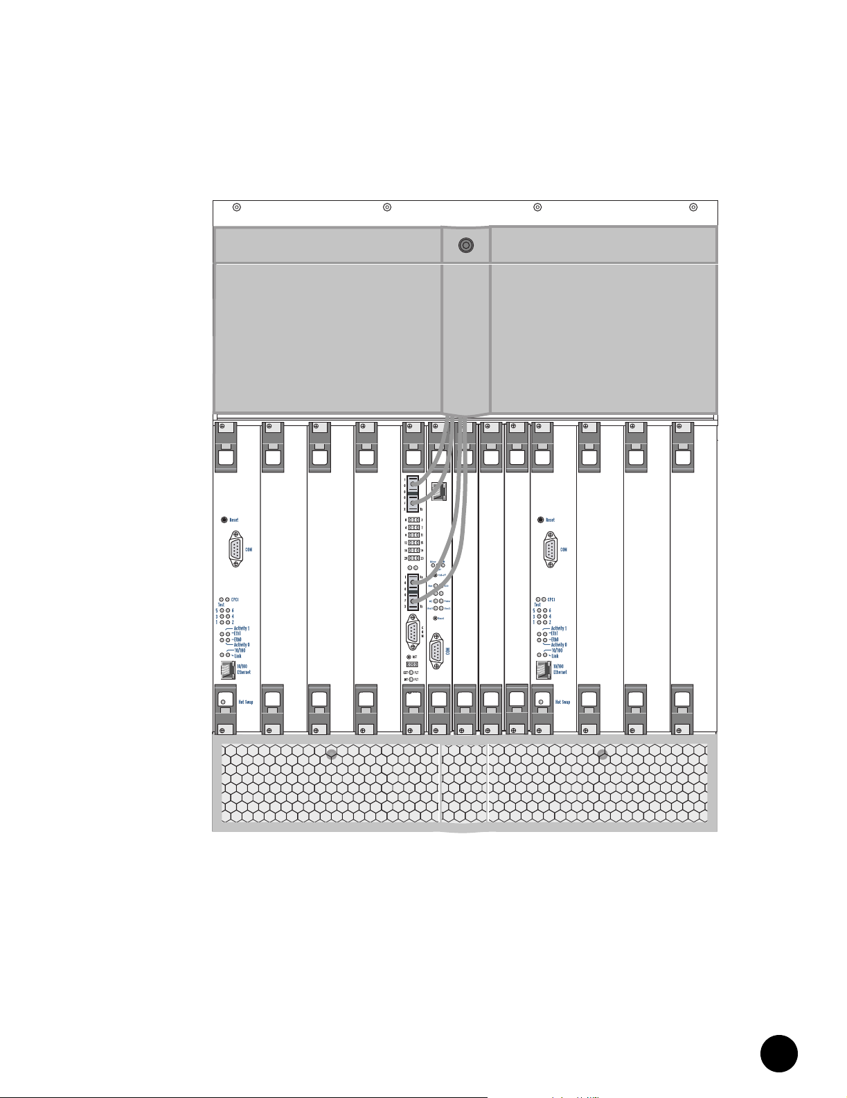
Cabling a NIC Module
Figure 15: NIC Module Cabling – Front View
Power
Power
Fault
Fault
•
•
•
•
•
•
•
•
Power
Power
Fault
Power
Fault
Fault
Power
Power
Fault
Power
Fault
Fault
•
•
•
•
•
•
•
•
•
•
•
•
•
•
•
•
•
•
•
•
•
•
•
•
•
•
•
•
•
•
•
•
•
•
•
•
•
•
•
•
•
•
•
•
•
•
•
•
•
•
G10 CMTS Installation
27
Page 40

Cabling a NIC Access Module
•
Cabling a NIC Access Module
•
•
•
•
•
•
•
•
•
•
•
•
•
•
•
•
•
•
•
•
•
•
•
•
•
•
•
•
•
•
•
•
•
•
•
•
•
•
•
•
•
•
•
•
•
•
•
•
•
•
•
•
•
•
•
•
•
This section describes how to interconnect up to two NIC Access Modules to multiple HFC
Connector Modules in a non-redundant configuration. The procedure assumes that a NIC
Module only supports the DOCSIS Modules installed in the same domain of the chassis.
Therefore, if five or more DOCSIS Modules are installed in the system, then two NIC Modules
are installed to support them. In addition, the procedure assumes that DOCSIS Modules are
installed in the following slot order: 1, 2, 3, 4, 10, 11, 12, 13.
The NIC Access Module cables are used to interconnect the Fast Ethernet ports of the HFC
Connector Modules to the NIC Access Module. The 12 RJ-45 connectors on the NIC Access
Module cable plugged into the connector labeled “2” on the NIC Access Module can be used
as general purpose switched FastEthernet ports. Refer to Table 1 on page 18 for details.
1. If applicable, remove the protective cover that is inserted into the RJ-21 end of the NIC
2. Firmly insert the RJ-21 end of the cable into the connector labeled “1” on the NIC Access
3. Tighten the two cable retainer screws by applying 4 in lb of torque to each of the screws.
4. Locate the RJ-45 connectors of the NIC Access Module cable labeled “PORT 5” and
5. Locate the RJ-45 connectors of the NIC Access Module cable labeled “PORT 7” and
6. Locate the RJ-45 connectors of the NIC Access Module cable labeled “PORT 9” and
7. Locate the RJ-45 connectors of the NIC Access Module cable labeled “PORT 11” and
In this particular procedure, the RJ-45 ports of the CCM
Access Module labeled “Eth0” and “Eth1” are unused.
It is recommended that the following procedure be
followed to allow for future wiring considerations.
Access Module cable.
Module in slot 5 (refer to Figure 14 on page 26).
“PORT 6” and plug them into the RJ-45 ports of the HFC Connector Module in slot 1
labeled “Eth0” and “Eth1,” respectively (refer to Figure 12 on page 22 for port labeling).
If an HFC Connector Module is installed in slot 2, proceed to Step 5; otherwise, jump
ahead to Step 15.
“PORT 8” and plug them into the RJ-45 ports of the HFC Connector Module in slot 2
labeled “Eth0” and “Eth1,” respectively. If an HFC Connector Module is installed in slot
3, proceed to Step 6; otherwise, jump ahead to Step 15.
“PORT 10” and plug them into the RJ-45 ports of the HFC Connector Module in slot 3
labeled “Eth0” and “Eth1,” respectively. If an HFC Connector Module is installed in slot
4, proceed to Step 7; otherwise, jump ahead to Step 15.
“PORT 12” and plug them into the RJ-45 ports of the HFC Connector Module in slot 4
labeled “Eth0” and “Eth1,” respectively. If an HFC Connector Module is installed in slot
10, proceed to Step 8; otherwise, jump ahead to Step 15.
Juniper Networks G10 CMTS Getting Started
28
Page 41

Cabling a NIC Access Module
8. If you have reached this step in the procedure, then at least five HFC Connector Modules
are installed in the G10 CMTS, in which case a second NIC Access Module and its
corresponding cable are required to complete the interconnection procedure. If
applicable, remove the protective cover that is inserted into the RJ-21 end of the NIC
Access Module cable.
9. Firmly insert the RJ-21 end of the second NIC Access Module cable into the connector
labeled “1” on the NIC Access Module in slot 9 (refer to Figure 14 on page 26).
10. Tighten the two cable retainer screws by applying 4 in lb of torque to each of the screws.
11. Locate the RJ-45 connectors of the NIC Access Module cable labeled “PORT 5” and
“PORT 6” and plug them into the RJ-45 ports of the HFC Connector Module in slot 10
labeled “Eth0” and “Eth1,” respectively. If an HFC Connector Module is installed in slot
11, proceed to Step 12; otherwise, jump ahead to Step 15.
12. Locate the RJ-45 connectors of the second NIC Access Module cable labeled “PORT 7”
and “PORT 8” and plug them into the RJ-45 ports of the HFC Connector Module in slot
11 labeled “Eth0” and “Eth1,” respectively. If an HFC Connector Module is installed in
slot 12, proceed to Step 13; otherwise, jump ahead to Step 15.
13. Locate the RJ-45 connectors of the NIC Access Module cable labeled “PORT 9” and
“PORT 10” and plug them into the RJ-45 ports of the HFC Connector Module in slot 12
labeled “Eth0” and “Eth1,” respectively. If an HFC Connector Module is installed in slot
13, proceed to Step 14; otherwise, jump ahead to Step 15.
14. Locate the RJ-45 connectors of the NIC Access Module cable labeled “PORT 11 and
“PORT 12” and plug them into the RJ-45 ports of the HFC Connector Module in slot 13
labeled “Eth0” and “Eth1,” respectively.
15. At this point, all of the Ethernet ports of the HFC Connector Modules should be
connected to the NIC Access Module. Figure 16 on page 30 provides an illustration of
these connections (without the HFC Connector Module coaxial cables shown).
16. All used and unused Ethernet cable wires on either NIC Access Module cable should be
dressed appropriately and routed to avoid obstructing the rear connections of the G10
CMTS.
Table 2 on page 31 summarizes the NIC Access Module wiring plan used in this procedure.
The “Module – Slot / Port” headings specify the module name, the slot in which the module is
installed, and the RJ-45 port label of the module.
•
•
•
•
•
•
•
•
•
•
•
•
•
•
•
•
•
•
•
•
•
•
•
•
•
•
•
•
•
•
•
•
•
•
•
•
•
•
•
•
•
•
•
•
•
•
•
•
•
•
•
•
•
•
•
•
•
•
G10 CMTS Installation
29
Page 42

Cabling a NIC Access Module
•
Figure 16: NIC Access Module Cable Connections
•
•
•
•
•
•
•
•
•
•
•
•
•
•
•
•
•
•
•
•
•
S 0
D
0
US
DS 1
1
US
S 2
D
US 2
DS 3
US 3
•
•
•
•
Eth0
Eth1
0
S
D
0
US
S 1
D
US 1
S 2
D
2
US
S 3
D
US 3
Eth0
Eth1
•
•
•
•
•
•
•
•
•
•
•
•
•
•
•
•
•
•
•
•
•
•
•
•
•
•
•
•
•
•
•
•
DS 0
S 0
D
US 0
S 1
S 0
D
0
OPERATIONAL
OPERATIONAL
EXT FAULT
INT FAULT
POWER
0
DS
S 0
D
US 0
S 1
0
US
1
US
2
US
US 3
Eth0
Eth1
D
DS 1
1
US
S 2
D
S 2
D
2
US
S 3
D
DS 3
US 3
Eth0
1
Eth
Eth0
Eth
POWER
C
O
C
M
O
M
Eth0
Eth1
1
S 0
D
EXT FAULT
INT FAULT
0
US
S 1
D
1
US
S 2
D
US C
DS 3
D
US
Eth1
Eth2
US
0
US
1
DS
1
US
US 1
S 2
D
US 2
US 2
DS 3
US 3
US 3
Eth0
Eth0
Eth1
Eth2
D
1
S
D
1
US
2
S
D
2
DS
2
US
S 3
D
S 3
D
US 3
Eth0
Eth1
Juniper Networks G10 CMTS Getting Started
30
Page 43

Attaching a PC to the Chassis Control Module
Table 2: NIC Access Module Wiring Plan
NIC Access Module 5
Cable/Port Module – Slot/Port
Cable 1 / PORT 1 Reserved Cable 1 / PORT 1 Reserved
Cable 1 / PORT 2 Reserved Cable 1 / PORT 2 Reserved
Cable 1 / PORT 3 Reserved Cable 1 / PORT 3 Reserved
Cable 1 / PORT 4 Reserved Cable 1 / PORT 4 Reserved
Cable 1 / PORT 5 HFC – 1 / Eth0 Cable 1 / PORT 5 HFC – 10 / Eth0
Cable 1 / PORT 6 HFC – 1 / Eth1 Cable 1 / PORT 6 HFC – 10 / Eth1
Cable 1 / PORT 7 HFC – 2 / Eth0 Cable 1 / PORT 7 HFC – 11 / Eth0
Cable 1 / PORT 8 HFC – 2 / Eth1 Cable 1 / PORT 8 HFC – 11 / Eth1
Cable 1 / PORT 9 HFC – 3 / Eth0 Cable 1 / PORT 9 HFC – 12 / Eth0
Cable 1 / PORT 10 HFC – 3 / Eth1 Cable 1 / PORT 10 HFC – 12 / Eth1
Cable 1 / PORT 11 HFC – 4 / Eth0 Cable 1 / PORT 11 HFC – 13 / Eth0
Cable 1 / PORT 12 HFC – 4 / Eth1 Cable 1 / PORT 12 HFC – 13 / Eth1
Cable 2 / PORT 1 FastEthernet or Unused
Cable 2 / PORT 2 FastEthernet or Unused1Cable 2 / PORT 2 FastEthernet or Unused
Cable 2 / PORT 3 FastEthernet or Unused1Cable 2 / PORT 3 FastEthernet or Unused
Cable 2 / PORT 4 FastEthernet or Unused1Cable 2 / PORT 4 FastEthernet or Unused
Cable 2 / PORT 5 FastEthernet or Unused1Cable 2 / PORT 5 FastEthernet or Unused
Cable 2 / PORT 6 FastEthernet or Unused1Cable 2 / PORT 6 FastEthernet or Unused
Cable 2 / PORT 7 FastEthernet or Unused1Cable 2 / PORT 7 FastEthernet or Unused
Cable 2 / PORT 8 FastEthernet or Unused1Cable 2 / PORT 8 FastEthernet or Unused
Cable 2 / PORT 9 FastEthernet or Unused1Cable 2 / PORT 9 FastEthernet or Unused
Cable 2 / PORT 10 FastEthernet or Unused1Cable 2 / PORT 10 FastEthernet or Unused
Cable 2 / PORT 11 FastEthernet or Unused1Cable 2 / PORT 11 FastEthernet or Unused
Cable 2 / PORT 12 FastEthernet or Unused1Cable 2 / PORT 12 FastEthernet or Unused
1. These ports can be used as general purpose switched Fast Ethernet ports; otherwise, these connectors are unused.
Ports 1–12 on Cable 2 correspond to FastEthernet ports 0–11, respectively, under the interface fastEthernet sub-mode
for the NIC Module.
Attaching a PC to the Chassis Control Module
Initial configuration of the G10 CMTS requires a direct connection between a personal
computer (PC) and the Chassis Control Module. Using the DB-9– to–DB-9 null modem serial
cable supplied in the accessory kit, connect one end of the cable to the RS-232 DB-9 port
labeled COM on the Chassis Control Module front panel (refer to Figure 13 on page 24), and
connect the other end to the serial port on your PC.
An adapter may be needed to connect the DB-9 connector
of the cable to the serial port of your PC (for example,
DB-9–to–DB-25).
NIC Access Module 9
Cable/Port Module – Slot/Port
1
Cable 2 / PORT 1 FastEthernet or Unused
•
•
•
•
•
•
•
•
•
•
•
•
•
•
•
•
•
•
•
1
1
1
1
1
1
1
1
1
1
1
1
•
•
•
•
•
•
•
•
•
•
•
•
•
•
•
•
•
•
•
•
•
•
•
•
•
•
•
•
•
•
•
•
•
•
•
•
•
•
•
G10 CMTS Installation
31
Page 44

Connecting to Power Sources
•
Connecting to Power Sources
•
•
•
•
•
•
•
•
•
•
AC Power
•
•
•
•
•
•
•
•
•
•
•
•
•
•
•
•
•
•
•
•
•
•
•
•
•
•
•
•
•
•
•
•
•
•
•
•
•
•
•
•
•
•
•
•
•
•
•
Each AC power transition module in the G10 CMTS chassis contains a standard IEC 15-A
three-prong male AC power receptacle for connecting to an AC power source (refer to
Figure 3 on page 4). Facing the rear of the chassis, the AC power transition modules on the
right and left sides of the chassis independently support the power supplies in Domain A and
Domain B, respectively.
The following procedure describes the steps for connecting the AC power transition modules
to their power sources (refer to Figure 17 on page 33):
1. Ensure that the rocker switch on each AC power transition module is in the OFF (O)
2. Swing the power cord retainer clips to their upright position, plug the female end of each
3. Plug the male end of each 15-A power cord to independent power sources. Always use
Ensure that you have read and taken the proper safety
precautions as described in the Juniper Networks G10 CMTS
Installation and Configuration manual prior to connecting
any power source to the G10 CMTS.
To enhance the redundancy capabilities, each power
transition module must be powered by sources on
different circuits.
position.
15-A power cord supplied with your shipment into the AC power receptacle on each AC
power transition module, then close the retainer clips so that they clasp around the
power cords.
AC power sources that support the ground prong of the power cord.
The G10 CMTS power supplies are autosensing which
enables them for usage with 110 VAC or 220 VAC.
Juniper Networks G10 CMTS Getting Started
32
Page 45

Connecting to Power Sources
Figure 17: AC Power Cord and Retainer Clip
DC Power
Each DC power transition module in the G10 CMTS chassis contains a terminal block for
connecting to a DC power source (refer to Figure 18 on page 34). Unlike the AC
configuration, the DC power transition modules do not operate independently. Each DC
power transition module supports the power supplies in both domains of the chassis.
The following procedure describes the steps for connecting the DC power transition modules
to their power sources:
1. Shipped with the G10 CMTS are ring lugs that are used to connect the DC power cord to
the DC power transition module terminal block. These ring lugs must be crimped to the
negative (–) and positive (+) wires of the DC power cord in order to properly connect to
the DC power transition module.
2. Remove the screw from the negative (–) terminal on the terminal block of the DC power
transition module, insert the screw through the ring lug of the power cord that will be
attached to the negative (–) terminal of the DC power source, and tighten the screw into
the negative (–) terminal on the terminal block. Apply 20 in lb of torque to the screw.
3. Remove the screw from the positive (+) terminal on the terminal block of the DC power
transition module, insert the screw through the ring lug of the power cord that will be
attached to the positive (+) terminal of the DC power source, and tighten the screw into
the positive (+) terminal on the terminal block. Apply 20 in lb of torque to the screw.
Power Cord
Retainer Clip
To enhance the redundancy capabilities, it is
recommended that each power transition module be
powered by sources on different circuits.
•
•
•
•
•
•
•
•
•
•
•
•
•
•
•
•
•
•
•
•
•
•
•
•
•
•
•
•
•
•
•
•
•
•
•
•
•
•
•
•
•
•
•
•
•
•
•
•
•
•
•
•
•
•
•
•
•
•
G10 CMTS Installation
33
Page 46

Connecting to Power Sources
•
•
•
•
•
•
•
•
•
•
Figure 18: DC Power Transition Module
•
•
•
•
•
•
•
•
•
•
•
•
•
•
•
•
•
•
•
•
•
•
•
•
•
•
•
•
•
•
•
•
•
•
•
•
•
•
•
•
•
•
•
•
•
•
•
•
4. Connect the other end of the power cord connected to the negative (–) terminal on the
terminal block of the DC power transition module to the negative (–) terminal of the DC
power source in accordance with the manufacturer’s specifications.
5. Connect the other end of the power cord connected to the positive (+) terminal on the
terminal block of the DC power transition module to the positive (+) terminal of the DC
power source in accordance with the manufacturer’s specifications.
Juniper Networks G10 CMTS Getting Started
34
Page 47

Chapter 3
G10 CMTS Configuration
This chapter describes the configuration procedure for the G10 CMTS. It is assumed that the
installation procedures described in “G10 CMTS Installation” on page 9 have been followed
prior to performing the procedures presented in this chapter. It is recommended that the
entire configuration process in this chapter be read prior to performing the actual G10 CMTS
configuration.
Powering On the G10 CMTS
The following steps define the power-on procedure and the expected state of the LEDs on the
power supplies, fan trays, and module panels that should be monitored after the G10 CMTS is
powered on. If the G10 CMTS does not power up correctly, refer to the Juniper Networks G10
CMTS Installation and Configuration manual for the possible causes and corresponding
actions to take.
1. Ensure that the power sources connected to the power transition modules are on.
2. If the G10 CMTS is AC-powered, press the rocker switch on each AC power transition
3. Remove the power supply faceplate by pulling the flanges on each side of the faceplate
4. Replace the power supply faceplate by aligning its four ball studs with the four power
5. Ensure that the fan tray LEDs (two in front, one in rear) are not illuminated (refer to
module to the ON (|) position. There is no requirement that the two power switches be
turned on in any particular order. If the G10 CMTS is DC-powered, the system will be
powered up when the DC power transition modules have been connected to the DC
power sources.
away from the chassis until the faceplate ball studs are removed from the power supply
faceplate clips.Ensure that all power supplies are operating normally by checking that
the POWER LED is illuminated green and the FAULT LED is not illuminated.
supply faceplate clips and pressing the faceplate towards the chassis until it snaps into
place.
Figure 1 on page 2 and Figure 3 on page 4 for the location of these LEDs).
To minimize the risk of damage to the G10 CMTS, a failed
fan tray should be replaced as soon as possible to ensure
that proper air ventilation occurs throughout the chassis.
•
•
•
•
•
•
•
•
•
•
•
•
•
•
•
•
•
•
•
•
•
•
•
•
•
•
•
•
•
•
•
•
•
•
•
•
•
•
•
•
•
•
•
•
•
•
•
•
G10 CMTS Configuration
35
Page 48

Powering On the G10 CMTS
•
•
•
•
•
•
•
•
•
•
•
•
•
•
•
•
•
•
•
•
•
•
•
•
•
•
•
•
•
•
•
•
•
•
•
•
•
•
•
•
•
•
•
•
•
•
•
•
•
•
•
•
•
•
•
•
•
•
6. Immediately after the G10 CMTS is powered on, check that the Test LED on every
DOCSIS Module faceplate is green and blinking (refer to Figure 19 on page 37). This
indicates that the module’s self test is running. Continue to monitor each module’s Test
LED until it stops blinking, at which point a green illuminated LED indicates the
successful completion of that module’s self test. LEDs 1 through 6 should be green,
indicating all software has been successfully loaded and initialized.
7. Immediately after the G10 CMTS is powered on, check that the Power LED on the
Chassis Control Module faceplate is green (refer to Figure 19 on page 37).
8. Immediately after the G10 CMTS is powered on, wait for the OK LED on the NIC Module
faceplate to illuminate green, which indicates the module initialization has been
successfully completed (refer to Figure 20 on page 38).
9. The OPERATIONAL LED at the top of the NIC Access Module rear panel should be
illuminated green after confirming the OK LED on its corresponding NIC Module is in the
correct state as described in the previous step (refer to Figure 20 on page 38).
Juniper Networks G10 CMTS Getting Started
36
Page 49

Powering On the G10 CMTS
Figure 19: DOCSIS Module and Chassis Control Module Front Panels
Eth0
Hot Swap
•
•
•
•
•
•
•
•
•
•
•
•
•
•
•
•
•
•
•
•
•
•
•
•
•
•
•
•
•
•
•
•
•
•
•
•
•
•
•
•
•
•
•
•
•
•
•
•
•
•
•
•
•
•
•
•
•
•
G10 CMTS Configuration
37
Page 50

Powering On the G10 CMTS
•
Figure 20: NIC Module and NIC Access Module Panels
•
•
•
•
•
•
•
•
•
•
•
•
PULL
OPERATIONAL
EXT FAULT
G
B
I
C
INT FAULT
POWER
•
•
•
•
•
•
•
•
•
GB1 GB0
1
•
•
•
•
•
•
•
G
B
I
C
•
•
•
•
2
•
•
•
CLK PWR RTM OK
•
•
•
•
•
•
•
•
•
•
•
•
•
•
•
•
•
•
•
•
•
•
Juniper Networks G10 CMTS Getting Started
38
Page 51

Powering On and Configuring the PC
Powering On and Configuring the PC
1. Power on the personal computer (PC) attached to the serial port of the Chassis Control
Module.
2. Launch your asynchronous terminal emulation application (such as Microsoft Windows
Hyperterminal), and establish a direct connection. Configure the port settings as follows:
Bits per second: 9600
Data bits: 8
Parity: None
Stop bits: 1
Flow control: None
3. When a successful connection is made between the PC and the G10 CMTS, the terminal
emulation screen on your PC will display a banner and prompt you for a login
username:
Copyright (c) 2000-2002 Juniper Networks, Inc.
G10 CMTS Release sw_rev_num
Login:
where:
sw_rev_num represents the software revision number
Logging In and Out of the G10 CMTS
1. Type root at the login prompt and press ENTER:
Login: root ↵
2. You will then be prompted for a password. Type changeme as the password and press
ENTER:
Password: changeme ↵
You will see the following Command Line Interface (CLI) system prompt:
G10$root#
3. If desired, you can logout of the system as follows:
G10$root# logout↵
•
•
•
•
•
•
•
•
•
•
•
•
•
•
•
•
•
•
•
•
•
•
•
•
•
•
•
•
•
•
•
•
•
•
•
•
•
•
•
•
•
•
•
•
•
•
•
•
•
•
•
•
•
•
•
•
•
•
G10 CMTS Configuration
39
Page 52

Configuring the G10 CMTS
•
Configuring the G10 CMTS
•
•
•
•
•
•
•
•
•
•
•
•
•
•
•
•
•
•
•
•
•
•
•
•
•
•
•
•
•
•
•
•
Cable Interface Assignment
•
•
•
•
•
•
•
•
•
•
•
•
•
•
•
•
•
•
•
•
•
•
•
•
•
This section describes how to use the CLI to perform the initial configuration of the G10
CMTS. The complete details of the CLI can be found in the Juniper Networks G10 CMTS CLI
Reference manual.
The procedures provided herein describe how to configure the following:
Usernames and passwords
Miscellaneous parameters
Configuration file
Downstream channel parameters
Upstream channel parameters
A single cable interface consisting of one downstream channel and one upstream
channel on a DOCSIS Module/HFC Connector Module pair in slot 1
Two Fast Ethernet interfaces on a DOCSIS Module/HFC Connector Module pair in slot 1
Two Gigabit Ethernet interfaces on a NIC Module in slot 5
Management interface
These procedures are provided for illustration purposes. The actual parameters specified
during your initial configuration are dependent on your particular preferences, as well as
your network and HFC plant characteristics.
The G10 CMTS is shipped with a default cable interface assignment as presented in Table 3
through Table 5 on page 41. Note that the downstream and upstream channel to cable
interface assignments and the upstream channel to upstream port assignments specified in
these tables are the factory defaults, and can be changed through the CLI or the
startup-config file. The default assignments are used if the startup-config file does not assign
any downstream or upstream channels to a MAC domain. The procedures in this chapter
assume this default assignment.
Some of the CLI commands used in the following
procedures set various parameters to their default values
and hence their execution is not mandatory. These
commands are provided for illustration purposes.
Juniper Networks G10 CMTS Getting Started
40
Page 53

Configuring the G10 CMTS
Table 3: Downstream Channel Assignment
Cable Interface Downstream Channel Downstream Port
00DS 0
11DS 1
22DS 2
33DS 3
Table 4: Upstream Channel Assignment (8-Channel DOCSIS Module)
Cable Interface Upstream Channel Upstream Port
00US 0
1
12US 1
3
24US 2
5
36US 3
7
Table 5: Upstream Channel Assignment (16-Channel DOCSIS Module)
Cable Interface Upstream Channel Upstream Port
0
0
1
2
3
1
8
9
2
3
10
11
4
5
12
13
6
7
14
15
US 0
US 1
US 2
US 3
•
•
•
•
•
•
•
•
•
•
•
•
•
•
•
•
•
•
•
•
•
•
•
•
•
•
•
•
•
•
•
•
•
•
•
•
•
•
•
•
•
•
•
•
•
•
•
•
•
•
•
•
•
•
•
•
•
•
G10 CMTS Configuration
41
Page 54

Configuring the G10 CMTS
•
Creating Usernames and Passwords
•
•
•
•
1. At the initial CLI command prompt, you are in the read-write privilege mode. If desired,
you can enter the configure terminal mode and change your password from the default
of changeme:
•
•
•
G10$root# configure terminal↵
G10$root(config)# username root password myword↵
•
•
•
•
•
conf t can be used as an abbreviation for the configure
terminal command.
•
•
•
•
•
2. You may also want to create new usernames and passwords. Because you are in the
privilege mode, any newly created username will have privilege mode access:
•
•
G10$root(config)# username newuser password myword↵
•
•
•
Configuring Miscellaneous Parameters
•
•
If desired, the following miscellaneous parameters can be assigned:
•
•
Set the Hostname to Hub1-G10:
•
•
•
G10$root(config)# hostname Hub1-G10↵
Hub1-G10$root(config)#
•
•
•
Set the SNMP read-only and read-write SNMP password community strings to public and
private, respectively:
•
•
•
•
•
•
•
•
•
G10$root(config)# snmp-server community public ro↵
G10$root(config)# snmp-server community private rw↵
Set the time to 2:30pm and the date to December 22, 2001 (you must first exit to the top
level):
G10$root(config)# exit↵
G10$root# clock set 143000 22 12 2001↵
•
•
Viewing and Saving Running Configuration
•
•
•
•
•
•
•
•
•
•
To view the current configuration of the G10 CMTS, execute the following command:
G10$root# show running-config↵
To save the current configuration of the G10 CMTS, execute the following command. Upon
booting up, the system uses the startup-config file to set the configuration:
G10$root# copy running-config startup-config↵
•
•
•
•
Juniper Networks G10 CMTS Getting Started
42
Page 55

Configuring the G10 CMTS
Configuring Downstream Channel Parameters
The procedure in this section specifies various parameters for downstream channel 0 of
slot 1 / interface 0. The available downstream channels on a DOCSIS Module are channels
0–3, which always correspond to downstream ports 0–3, respectively, on the HFC Connector
Module. Table 6 provides the valid ranges of all parameters specified in this section.
Table 6: Downstream Channel Parameter Ranges
Parameter Range
slot 1–4, 10–13
interface 0–3
channel (=port) 0–3
frequency DOCSIS: 91000000 to 857000000
EuroDOCSIS: 109000000 to 861000000
RF power 500 to 610 (tenths dBmV)
modulation 64qam or 256qam
interleave depth 8, 16, 32, 64, 128
1. Enter the interface cable sub-mode, specifying slot 1 and interface 0:
G10$root# configure terminal↵
G10$root(config)# interface cable 1/0↵
2. Specify a frequency of 453000000 Hz for downstream channel 0:
G10$root(config-if-c1/0)# cable downstream 0 frequency 453000000↵
3. Specify an RF power of 55 dBmV for downstream channel 0:
G10$root(config-if-c1/0)# cable downstream 0 rf-power 55↵
4. Specify 64qam modulation for downstream channel 0:
G10$root(config-if-c1/0)# cable downstream 0 modulation 64qam↵
5. Specify an interleave depth of 8 for downstream channel 0:
G10$root(config-if-c1/0)# cable downstream 0 interleave-depth 8↵
6. At this point, if you desire to view the downstream channel 0 parameters and status,
enter the following command:
G10$root(config-if-c1/0)# cable downstream 0 show↵
7. Enable downstream channel 0:
G10$root(config-if-c1/0)# no cable downstream 0 shutdown↵
•
•
•
•
•
•
•
•
•
•
•
•
•
•
•
•
•
•
•
•
•
•
•
•
•
•
•
•
•
•
•
•
•
•
•
•
•
•
•
•
•
•
•
•
•
•
•
•
•
•
•
•
•
•
•
•
•
•
G10 CMTS Configuration
43
Page 56

Configuring the G10 CMTS
•
Configuring Upstream Channel Parameters
•
•
•
•
•
•
•
The procedure in this section specifies various parameters for upstream channel 0 of
slot 1 / interface 0. A default modulation profile for channel 0 will be used. The available
upstream channels on a DOCSIS Module are channels 0–7 or 0–15 (depending on the
DOCSIS Module model), and are assigned to the four upstream ports (0–3) on the HFC
Connector Module by default as defined in Table 4 on page 41. Table 7 provides the valid
ranges of all parameters specified in this section.
•
•
•
Table 7: Upstream Channel Parameter Ranges
•
•
•
•
•
•
•
•
•
•
Parameter Range
slot 1–4, 10–13
interface 0–3
channel 0–7 or 0–15 (depending on the DOCSIS Module model)
port 0–3
channel width 200000–3200000 Hz
frequency DOCSIS: 5000000 to 42000000
•
•
•
•
•
•
•
power-level -10 to +25 dBmV
data-backoff 0–16
range-backoff 0–16
modulation-profile 1–256
minislot-size 2, 4, 8, 16, 32, 64, 128
•
•
•
1. Specify a channel width of 200000 Hz for upstream channel 0:
•
•
G10$root(config-if-c1/0)# cable upstream 0 channel-width 200000↵
•
•
2. Specify a frequency of 5000000 Hz for upstream channel 0:
•
•
G10$root(config-if-c1/0)# cable upstream 0 frequency 5000000↵
•
•
•
•
•
•
•
•
•
•
•
•
•
•
•
3. Specify a power level of 0 dBmV for upstream channel 0:
G10$root(config-if-c1/0)# cable upstream 0 power-level 0↵
4. Specify start and stop data backoff values of 2 and 6, respectively, for upstream channel
0:
G10$root(config-if-c1/0)# cable upstream 0 data-backoff 2 6↵
5. Specify start and stop range backoff values of 3 and 7, respectively, for upstream
channel 0:
G10$root(config-if-c1/0)# cable upstream 0 range-backoff 3 7↵
6. Specify a minislot size of 8 for upstream channel 0:
•
•
G10$root(config-if-c1/0)# cable upstream 0 minislot-size 8↵
•
•
•
•
EuroDOCSIS: 5000000 to 65000000
Juniper Networks G10 CMTS Getting Started
44
Page 57

Configuring the G10 CMTS
7. At this point, if you desire to view the upstream channel 0 parameters and status, enter
the following command:
G10$root(config-if-c1/0)# cable upstream 0 show↵
8. Enable upstream channel 0:
G10$root(config-if-c1/0)# no cable upstream 0 shutdown↵
Configuring Fast Ethernet Interfaces
The procedure in this section enables the two Fast Ethernet interfaces on the DOCSIS
Module/HFC Connector Module pair in slot 1:
1. Exit back to the configure terminal mode:
G10$root(config-if-c1/0)# exit↵
2. Enter the interface fastEthernet sub-mode, specifying slot 1 and interface 0 for Fast
Ethernet port 0:
G10$root(config)# interface fastEthernet 1/0↵
3. Enable Fast Ethernet port 0:
G10$root(config-if-f1/0)# no shutdown↵
4. Exit back to the configure terminal mode:
G10$root(config-if-f1/0)# exit↵
5. Enter the interface fastEthernet sub-mode, specifying slot 1 and interface 1 for Fast
Ethernet port 1:
G10$root(config)# interface fastEthernet 1/1↵
6. Enable Fast Ethernet port 1:
G10$root(config-if-f1/1)# no shutdown↵
Configuring Gigabit Ethernet Interfaces
To configure and enable a Gigabit Ethernet interface, you must have a group-privilege of ip-rw
and you must enter the interface gigaEthernet sub-mode.
The procedure in this section enables the two Gigabit Ethernet interfaces on the NIC Module
slot 5:
1. Exit back to the configure terminal mode:
G10$root(config-if-f1/0)# exit↵
2. Enter the interface gigaEthernet sub-mode, specifying slot 5 and interface 0 for Gigabit
Ethernet port 0:
G10$root(config)# interface gigaEthernet 5/0↵
•
•
•
•
•
•
•
•
•
•
•
•
•
•
•
•
•
•
•
•
•
•
•
•
•
•
•
•
•
•
•
•
•
•
•
•
•
•
•
•
•
•
•
•
•
•
•
•
•
•
•
•
•
•
•
•
•
•
G10 CMTS Configuration
45
Page 58

Configuring the G10 CMTS
•
•
3. Enable Gigabit Ethernet port 0:
•
•
G10$root(config-if-g5/0)# no shutdown↵
•
•
•
•
•
•
•
•
•
•
•
•
•
4. Exit back to the configure terminal mode:
G10$root(config-if-g5/0)# exit↵
5. Enter the interface gigaEthernet sub-mode, specifying slot 5 and interface 1 for Gigabit
Ethernet port 1:
G10$root(config)# interface gigaEthernet 5/1↵
6. Enable Gigabit Ethernet port 1:
G10$root(config-if-g5/1)# no shutdown↵
•
•
Configuring a Management Interface
•
•
•
•
•
•
•
•
•
•
A management interface is established by using the Fast Ethernet port labeled “Eth0” on the
Chassis Control Module. The following procedure describes how to configure this interface:
1. Exit back to the configure terminal mode:
G10$root(config-if-f1/1)# exit↵
2. Assign an IP address of 192.177.122.3 for the default gateway for the management
interface:
•
•
G10$root(config)# ip default-gateway 192.177.122.3 management↵
•
•
•
•
•
•
•
•
•
•
3. Enter the interface fastEthernet sub-mode, specifying slot 6 and interface 0 for Fast
Ethernet port 0:
•
•
G10$root(config)# interface fastEthernet 6/0↵
•
•
•
4. Assign an IP address of 192.177.122.1 and a subnet mask of 255.255.255.0 for
slot 6 / interface 0:
•
•
G10$root(config-if-f6/0)# ip address 192.177.122.1 255.255.255.0↵
•
•
5. Enable Fast Ethernet port 0:
•
•
G10$root(config-if-f6/0)# no shutdown↵
•
•
•
•
•
•
Do not configure the Chassis Control Module management
port on a 169.254/16 network. These IP addresses are
used by the G10 CMTS internally, and any IP address
clashes can result in unpredictable behavior.
Juniper Networks G10 CMTS Getting Started
46
Page 59

Index
Index
1-Gigabit......................................................................25
Numerics
accessory kit..........................................................10, 31
A
air exhaust ..............................................................8, 12
air intake.................................................................7, 12
faceplate ................................................................7
faceplate clip..........................................................7
air management module ...........................................1, 7
air management panel ..................................1, 8, 18, 19
air ventilation ..................................................10, 15, 35
autosensing .................................................................32
Bits per second............................................................39
B
cable
C
coaxial............................................................21, 23
optical ..................................................................25
cable channel ....................................................7, 23, 25
cable guide ....................................................................7
cable plant...................................................................23
card guide .....................................................................7
card slot ......................................................................20
CCM Access Module ............................................1, 7, 19
channel .......................................................................21
width....................................................................44
chassis...............................................1, 7, 12, 13, 32, 33
air ventilation.......................................................35
mounting .............................................................12
Chassis Control Module ...........................1, 6, 17, 31, 36
chassis ground nuts.................................................7, 12
CLI see Command Line Interface
Command Line Interface.............................................39
configuration...............................................................40
data backoff.................................................................44
D
Data bits......................................................................39
DB-25 ..........................................................................31
DB-9 ............................................................................31
DOCSIS Module .......................................1, 6, 17, 23, 36
document conventions ..................................................x
Domain ...........................................................14, 17, 19
downstream ....................................................21, 23, 43
ejector ...................................................................14–20
E
equipment shelf.....................................................12, 13
ESD
ground strap.........................................................14
strap jack..............................................................14
strap plug ...............................................................7
Ethernet.................................................................25, 29
fan tray................................................................7, 8, 35
F
F-connector ...........................................................21, 23
flow control .................................................................39
GBIC ................................................................17, 18, 25
G
HFC Connector Module......................1, 7, 19–23, 28–29
H
IEC...............................................................................32
I
interleave depth...........................................................43
LED
L
FAULT ..................................................................35
•
•
•
•
•
•
•
•
•
•
•
•
•
•
•
•
•
•
•
•
•
•
•
•
•
•
•
•
•
•
•
•
•
•
•
•
•
•
•
•
•
•
•
•
•
•
•
•
Index
47
Page 60

Index
•
•
•
•
•
•
•
•
•
•
•
•
M
•
•
•
•
•
•
•
•
N
•
•
•
•
•
•
O
•
•
•
•
•
P
•
•
•
•
•
•
•
•
•
•
•
•
•
•
•
•
•
•
•
•
•
•
•
•
•
•
•
front fan tray....................................................7, 35
OK .......................................................................36
OPERATIONAL.....................................................36
POWER................................................................35
Power .................................................................. 36
rear fan tray.....................................................8, 35
Test......................................................................36
logout..........................................................................39
midplane.................................................................7, 16
minislot size................................................................44
modulation..................................................................43
module ejector rail ............................................7, 18, 20
mounting bracket........................................................13
NIC Access Module............................ 1, 7, 19, 28, 29, 36
NIC Module .......................................1, 6, 17, 23, 25, 36
node......................................................................21, 23
optical .........................................................................25
Parity ..........................................................................39
password.....................................................................42
PC .........................................................................31, 39
port
1-Gigabit .............................................................. 25
COM .................................................................... 31
DB-25...................................................................31
DB-9.....................................................................31
downstream...................................................21, 23
Ethernet......................................................... 25, 29
F-connector....................................................21, 23
GBIC.....................................................................25
RJ-21..............................................................28, 29
RJ-45..............................................................23, 28
RS-232 .................................................................31
serial .............................................................. 31, 39
upstream..............................................................23
power cord..................................................................32
power level..................................................................44
power receptacle
AC....................................................................8, 32
DC..........................................................................8
power source.........................................................32, 35
power supply.......................................................1, 7, 35
alignment.............................................................14
bay...................................................................7, 14
ejector rail........................................................7, 14
faceplate ............................7, 10, 14, 15, 23, 25, 35
faceplate clip..........................................................7
filler panel....................................................1, 7, 14
installation ...........................................................14
power switch
AC..............................................................8, 32, 35
power transition module
AC..............................................................8, 32, 35
DC..........................................................................8
rack mount..................................................................12
R
range backoff ..............................................................44
redundancy ...........................................................32, 33
RF power.....................................................................43
RJ-21 .....................................................................28, 29
RJ-45 .....................................................................23, 28
running-config file .......................................................42
shipping carton ...........................................................10
S
startup-config file.........................................................42
Stop bits ......................................................................39
terminal emulation......................................................39
T
upstream.........................................................23, 44, 45
U
username ....................................................................42
Juniper Networks G10 CMTS Getting Started
48
 Loading...