
Juniper Flow-Based and Packet-Based Processing User Manual

Junos® OS

Flow-Based and Packet-Based Processing User Guide for Security Devices

Published

2021-04-18

ii

Juniper Networks, Inc. 1133 nn v n Way Sunnyvale, California 94089 USA

408-745-2000 www.juniper.net

Juniper Networks, the Juniper Networks logo, Juniper, and Junos are registered trademarks of Juniper Networks, Inc. in the United States and other countries. All other trademarks, service marks, registered marks, or registered service marks are the property of their r s c v owners.

Juniper Networks assumes no responsibility for any inaccuracies in this document. Juniper Networks reserves the right to change, modify, transfer, or otherwise revise this b c n without n c

Junos® OS Flow-Based and Packet-Based Processing User Guide for Security Devices

Copyright © 2021 Juniper Networks, Inc. All rights reserved.

The n rm n in this document is current as of the date on the page.

YEAR 2000 NOTICE

Juniper Networks hardware and s ftw r products are Year 2000 compliant. Junos OS has no known m r

m ns through the year 2038. However, the NTP c n is known to have some c y in the year 2036.

END USER LICENSE AGREEMENT

The Juniper Networks product that is the subject of this technical

c m n

n consists of (or is intended for use

with) Juniper Networks s ftw r

Use of such s

ftw r

is subject to the terms and c n

ns of the End User License

Agreement ("EULA") posted at

s s

r

n r n

s

r

. By downloading, installing or using such

s ftw r you agree to the terms and c n

ns of that EULA.


iii

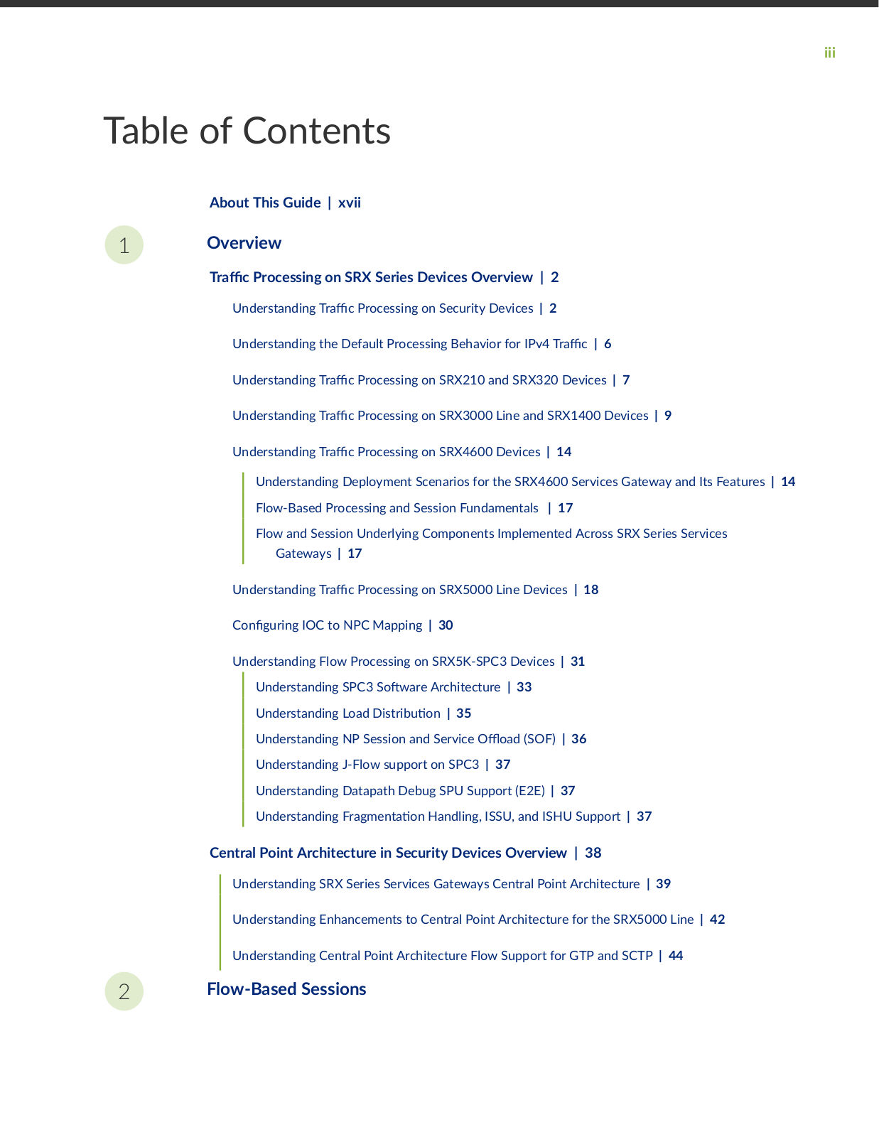
Table of Contents

About This Guide | xvii

1Overview

rc Processing on SRX Series Devices Overview | 2

Understanding r c Processing on Security Devices | 2

Understanding the Default Processing Behavior for IPv4 r c | 6

Understanding r c Processing on SRX210 and SRX320 Devices | 7

Understanding r c Processing on SRX3000 Line and SRX1400 Devices | 9

Understanding r c Processing on SRX4600 Devices | 14

Understanding Deployment Scenarios for the SRX4600 Services Gateway and Its Features | 14

Flow-Based Processing and Session Fundamentals | 17

Flow and Session Underlying Components Implemented Across SRX Series Services

Gateways | 17

Understanding r c Processing on SRX5000 Line Devices | 18

nr n IOC to NPC Mapping | 30

Understanding Flow Processing on SRX5K-SPC3 Devices | 31

Understanding SPC3 S

ftw r Architecture | 33

Understanding Load

s r b

n | 35


Understanding NP Session and Service ffl

(SOF) | 36

Understanding J-Flow support on SPC3 | 37


Understanding Datapath Debug SPU Support (E2E) | 37

Understanding r m n

n Handling, ISSU, and ISHU Support | 37

Central Point Architecture in Security Devices Overview | 38

Understanding SRX Series Services Gateways Central Point Architecture | 39

Understanding Enhancements to Central Point Architecture for the SRX5000 Line | 42

Understanding Central Point Architecture Flow Support for GTP and SCTP | 44

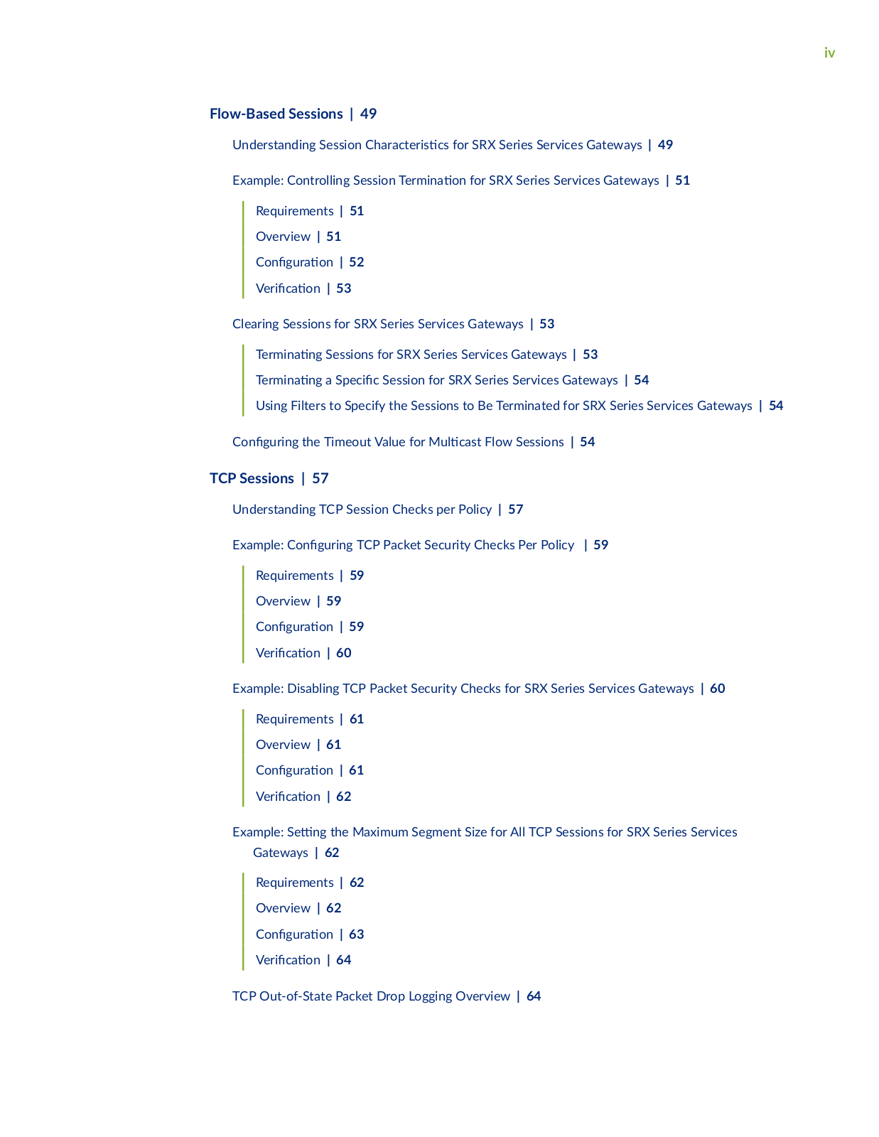
2Flow-Based Sessions

iv

Flow-Based Sessions | 49

Understanding Session

r c

r s cs for SRX Series Services Gateways | 49

Example: Controlling Session

rm n

n for SRX Series Services Gateways | 51


Requirements | 51


Overview | 51


n

r

n | 52


V r

c

n | 53


Clearing Sessions for SRX Series Services Gateways | 53


rm n

n

Sessions for SRX Series Services Gateways | 53


rm n

n

a S c

c Session for SRX Series Services Gateways | 54


Using Filters to Specify the Sessions to Be Terminated for SRX Series Services Gateways | 54


n

r n

the Timeout Value for M

c s Flow Sessions | 54

TCP Sessions | 57

Understanding TCP Session Checks per Policy | 57

Example: n r n TCP Packet Security Checks Per Policy | 59

Requirements | 59

Overview | 59

nr n | 59

V r c n | 60

Example: Disabling TCP Packet Security Checks for SRX Series Services Gateways | 60

Requirements | 61

Overview | 61

nr n | 61

V r c

n

| 62

Example: S

n

the Maximum Segment Size for All TCP Sessions for SRX Series Services

Gateways | 62

Requirements | 62

Overview | 62

nr n | 63

V r c n | 64

TCP Out-of-State Packet Drop Logging Overview | 64

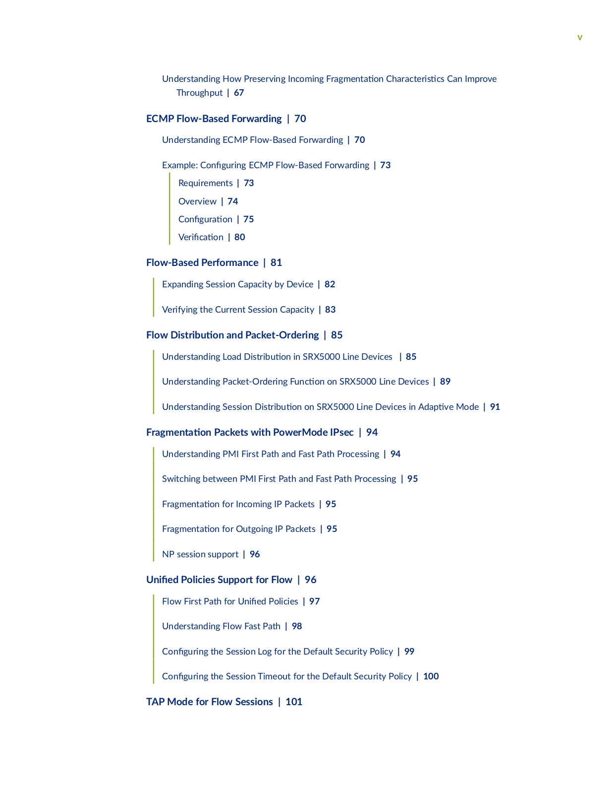
v

Understanding How Preserving Incoming r m n

n

r c r s cs Can Improve

Throughput | 67


ECMP Flow-Based Forwarding | 70

Understanding ECMP Flow-Based Forwarding | 70

Example: n r n ECMP Flow-Based Forwarding | 73

Requirements | 73

Overview | 74

nr n | 75

V r c n | 80

Flow-Based Performance | 81

Expanding Session Capacity by Device | 82

Verifying the Current Session Capacity | 83

Flow

s r b

n and Packet-Ordering | 85


Understanding Load

s r b

n in SRX5000 Line Devices | 85


Understanding Packet-Ordering nc n on SRX5000 Line Devices | 89


Understanding Session

s r b

n on SRX5000 Line Devices in

v Mode | 91

Fr m n

n Packets with PowerMode IPsec | 94


Understanding PMI First Path and Fast Path Processing | 94


Switching between PMI First Path and Fast Path Processing | 95


r

m n

n for Incoming IP Packets | 95


rm n n for Outgoing IP Packets | 95

NP session support | 96

nPolicies Support for Flow | 96

Flow First Path for n

Policies | 97

Understanding Flow Fast Path | 98

n

r n

the Session Log for the Default Security Policy | 99

n

r n

the Session Timeout for the Default Security Policy | 100

TAP Mode for Flow Sessions | 101

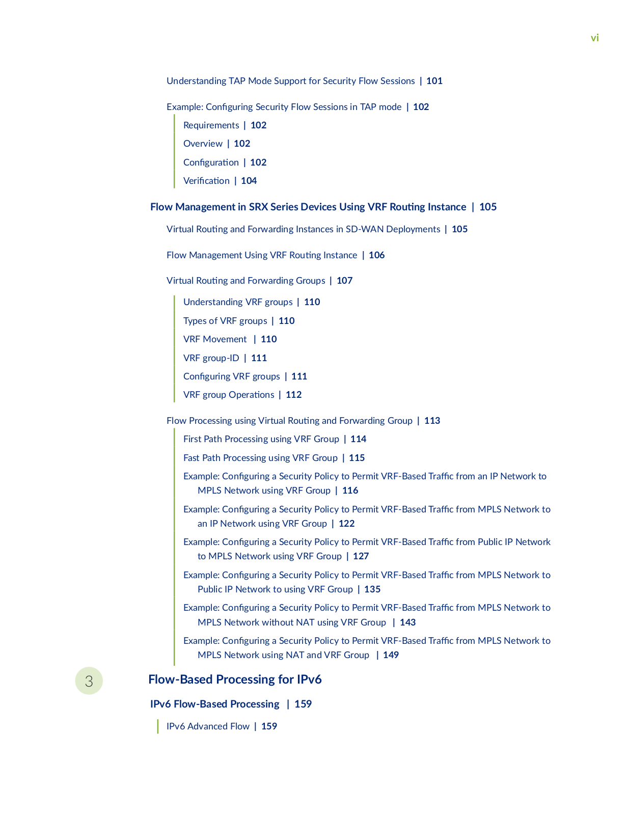
vi

Understanding TAP Mode Support for Security Flow Sessions | 101

Example: n r n Security Flow Sessions in TAP mode | 102

Requirements | 102

Overview | 102

nr n | 102

V r c n | 104

Flow Management in SRX Series Devices Using VRF R n Instance | 105

Virtual R n and Forwarding Instances in SD-WAN Deployments | 105

Flow Management Using VRF R n Instance | 106

Virtual R n and Forwarding Groups | 107

Understanding VRF groups | 110

Types of VRF groups | 110

VRF Movement | 110

VRF group-ID | 111

nr n VRF groups | 111


VRF group


r

ns | 112


Flow Processing using Virtual R n and Forwarding Group | 113


First Path Processing using VRF Group | 114


Fast Path Processing using VRF Group | 115


Example:

n

r n

a Security Policy to Permit VRF-Based

r

c from an IP Network to


MPLS Network using VRF Group | 116


Example:

n

r n

a Security Policy to Permit VRF-Based

r

c from MPLS Network to


an IP Network using VRF Group | 122


Example:

n

r n

a Security Policy to Permit VRF-Based

r

c from Public IP Network


to MPLS Network using VRF Group | 127


Example:

n

r n

a Security Policy to Permit VRF-Based

r

c from MPLS Network to


Public IP Network to using VRF Group | 135


Example:

n

r n

a Security Policy to Permit VRF-Based

r

c from MPLS Network to


MPLS Network without NAT using VRF Group | 143


Example:

n

r n

a Security Policy to Permit VRF-Based

r

c from MPLS Network to


MPLS Network using NAT and VRF Group | 149


3Flow-Based Processing for IPv6

IPv6 Flow-Based Processing | 159

IPv6 Advanced Flow | 159

vii

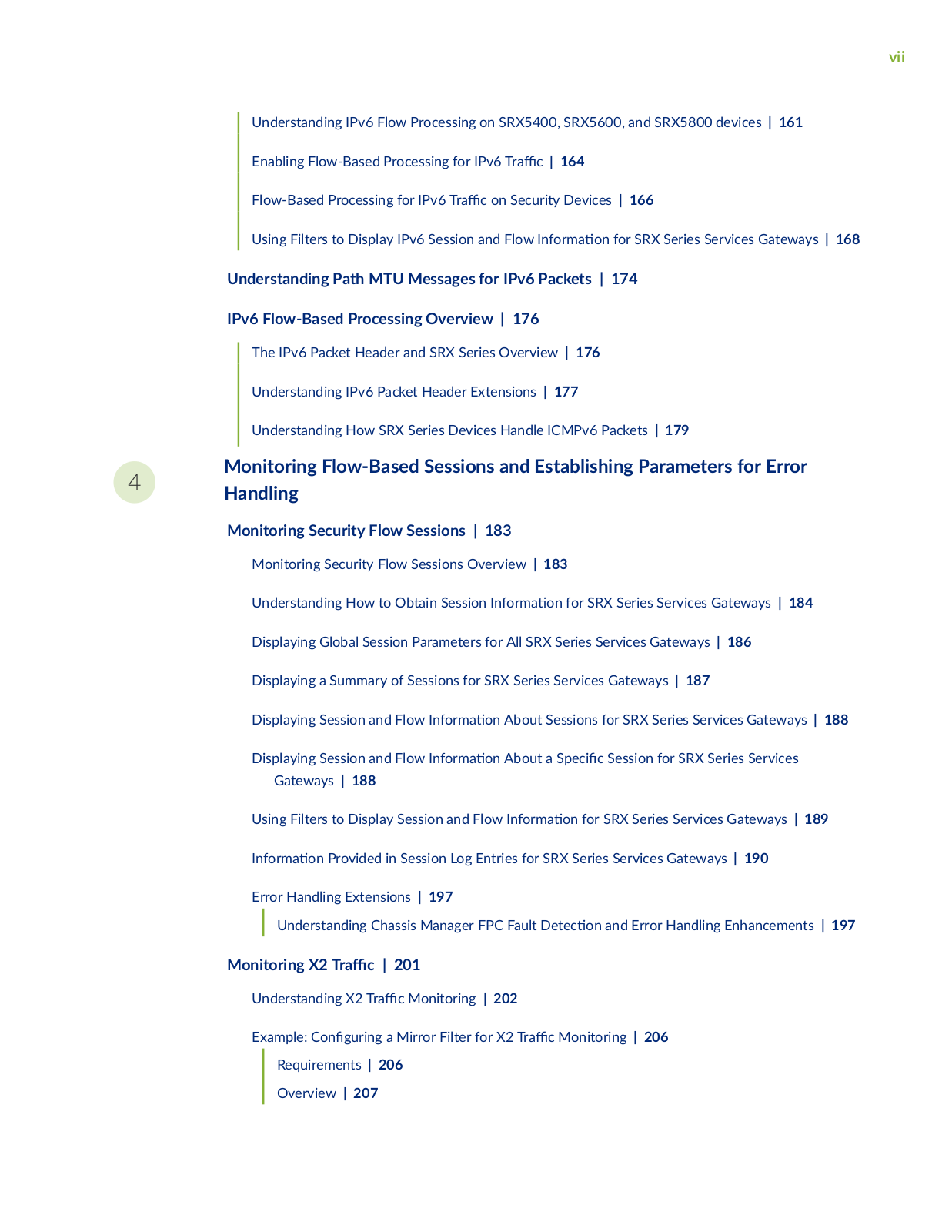
Understanding IPv6 Flow Processing on SRX5400, SRX5600, and SRX5800 devices | 161

Enabling Flow-Based Processing for IPv6 r c | 164

Flow-Based Processing for IPv6 r c on Security Devices | 166

Using Filters to Display IPv6 Session and Flow n rm n for SRX Series Services Gateways | 168

Understanding Path MTU Messages for IPv6 Packets | 174

IPv6 Flow-Based Processing Overview | 176

The IPv6 Packet Header and SRX Series Overview | 176

Understanding IPv6 Packet Header Extensions | 177

Understanding How SRX Series Devices Handle ICMPv6 Packets | 179

4

Monitoring Flow-Based Sessions and Establishing Parameters for Error

Handling


Monitoring Security Flow Sessions | 183


Monitoring Security Flow Sessions Overview | 183


Understanding How to Obtain Session n rm

n for SRX Series Services Gateways | 184


Displaying Global Session Parameters for All SRX Series Services Gateways | 186


Displaying a Summary of Sessions for SRX Series Services Gateways | 187


Displaying Session and Flow n

rm

n About Sessions for SRX Series Services Gateways | 188


Displaying Session and Flow n

rm

n About a S c

c Session for SRX Series Services


Gateways | 188


Using Filters to Display Session and Flow n rm

n for SRX Series Services Gateways | 189


n rm

n Provided in Session Log Entries for SRX Series Services Gateways | 190


Error Handling Extensions | 197


Understanding Chassis Manager FPC Fault

c

n and Error Handling Enhancements | 197


Monitoring X2 r

c | 201


Understanding X2 r

c Monitoring | 202


Example:

n

r n

a Mirror Filter for X2 r

c Monitoring | 206


Requirements | 206


Overview | 207


viii

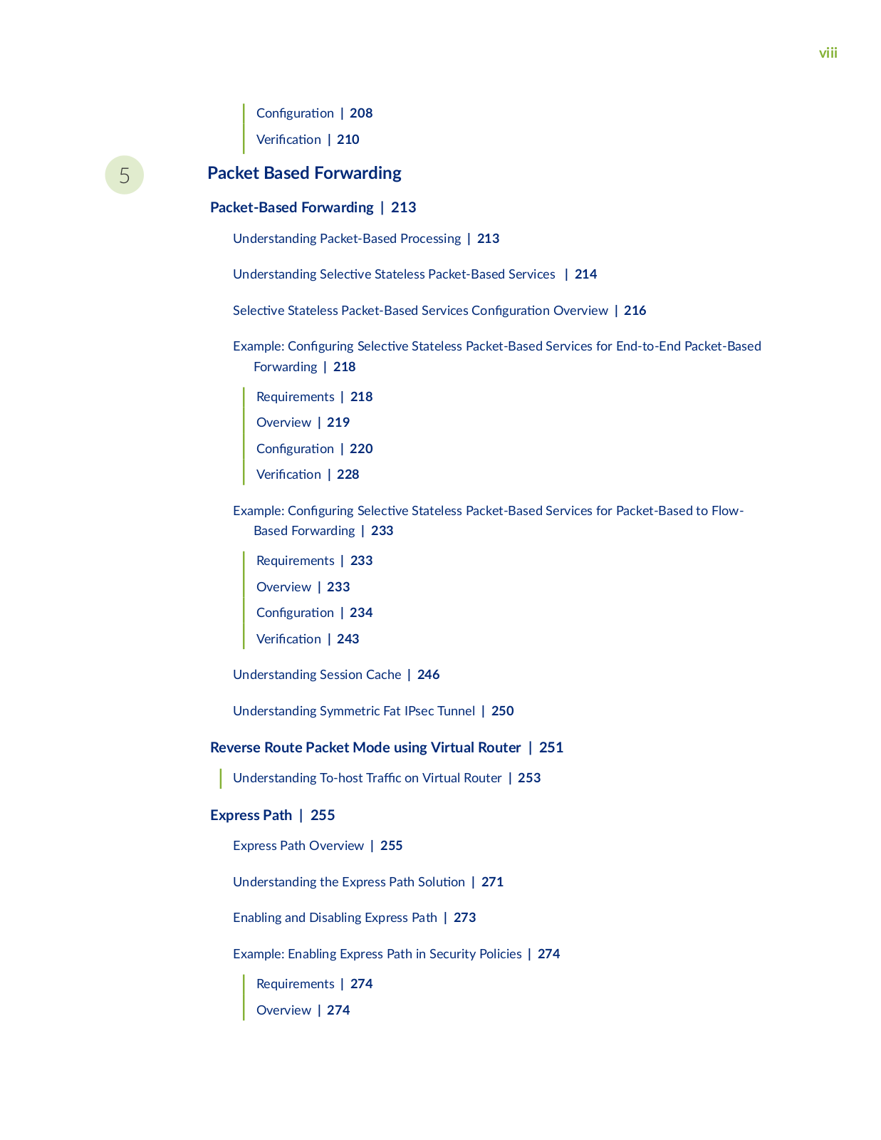
nr n | 208

V r c n | 210

5Packet Based Forwarding

Packet-Based Forwarding | 213

Understanding Packet-Based Processing | 213

Understanding S

c

v

Stateless Packet-Based Services | 214

S c v

Stateless Packet-Based Services n

r

n Overview | 216

Example:

n

r n

S

c v Stateless Packet-Based Services for End-to-End Packet-Based

Forwarding | 218

Requirements | 218

Overview | 219

nr n | 220

V r

c

n | 228

Example:

n

r n S c v Stateless Packet-Based Services for Packet-Based to Flow-

Based Forwarding | 233

Requirements | 233

Overview | 233

nr n | 234

V r c n | 243

Understanding Session Cache | 246

Understanding Symmetric Fat IPsec Tunnel | 250

Reverse Route Packet Mode using Virtual Router | 251

Understanding To-host r c on Virtual Router | 253

Express Path | 255

Express Path Overview | 255


Understanding the Express Path S

n | 271

Enabling and Disabling Express Path | 273

Example: Enabling Express Path in Security Policies | 274


Requirements | 274


Overview | 274


ix

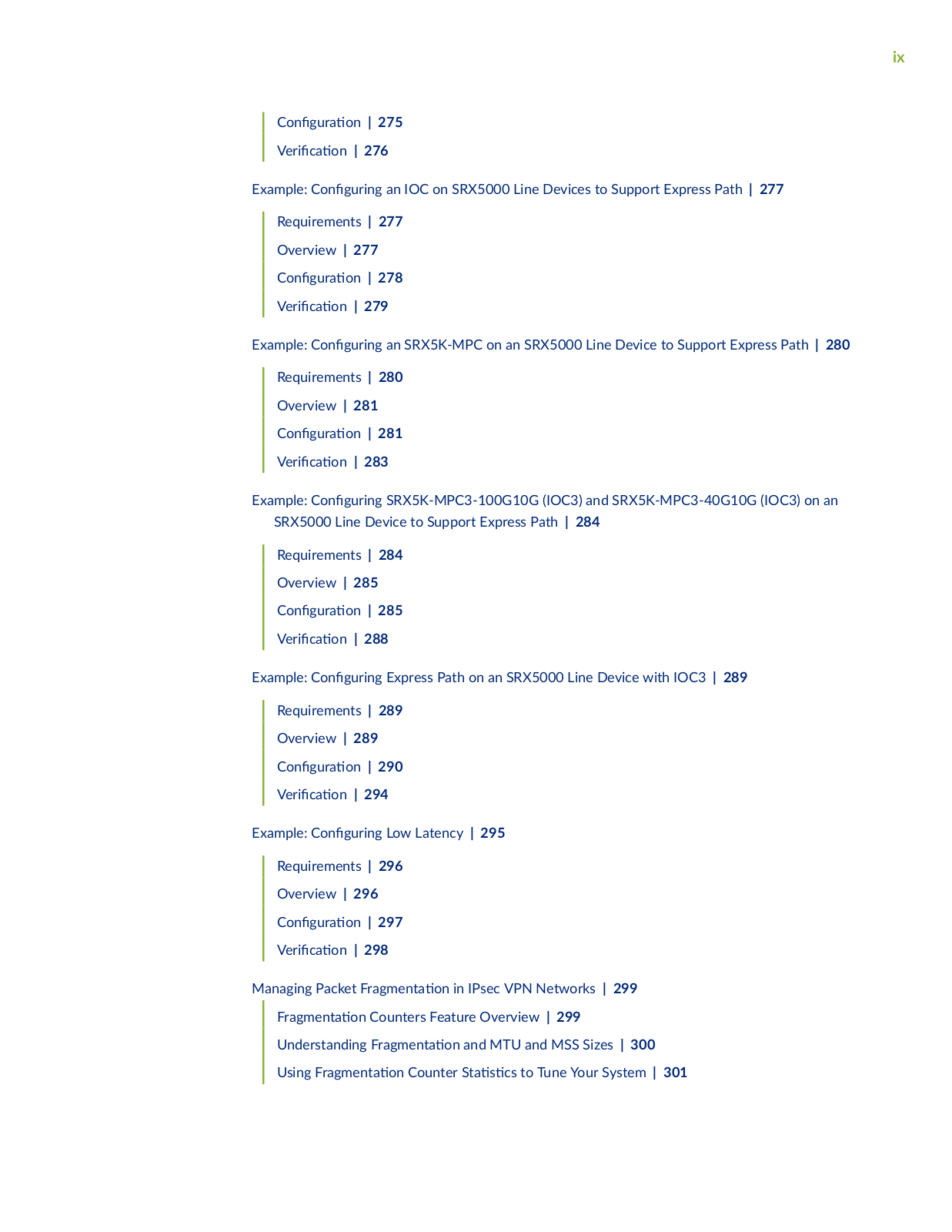
nr n | 275

V r

c

n | 276

Example:

n

r n an IOC on SRX5000 Line Devices to Support Express Path | 277

Requirements | 277

Overview | 277

nr n | 278

V r

c

n | 279

Example:

n

r n an SRX5K-MPC on an SRX5000 Line Device to Support Express Path | 280

Requirements | 280

Overview | 281

nr n | 281

V r c n | 283

Example: n r n SRX5K-MPC3-100G10G (IOC3) and SRX5K-MPC3-40G10G (IOC3) on an SRX5000 Line Device to Support Express Path | 284

Requirements | 284

Overview | 285

nr n | 285

V r

c

n | 288

Example:

n

r n Express Path on an SRX5000 Line Device with IOC3 | 289

Requirements | 289

Overview | 289

nr n | 290

V r c n | 294

Example: n r n Low Latency | 295

Requirements | 296

Overview | 296

nr n | 297

V r c n | 298

Managing Packet r m n n in IPsec VPN Networks | 299

rm n n Counters Feature Overview | 299

Understanding r

m n

n and MTU and MSS Sizes | 300

Using r m n

n Counter S s cs to Tune Your System | 301

x

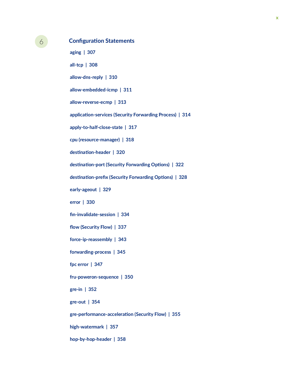
6

C n

r

n Statements


aging | 307


all-tcp | 308


allow-dns-reply | 310


allow-embedded-icmp | 311


allow-reverse-ecmp | 313


c

n s

rv c s (Security Forwarding Process) | 314


apply-to-half-close-state | 317


cpu (resource-manager) | 318


s

n

n


r | 320


s

n

n

r

(Security Forwarding

ns) | 322


s

n

n

r

x (Security Forwarding

ns) | 328


early-ageout | 329


error | 330


n

nv


s ss n | 334


fl w (Security Flow) | 337


force-ip-reassembly | 343


forwarding-process | 345


fpc error | 347


fru-poweron-sequence | 350


gre-in | 352


gre-out | 354


r


r rm nc

cc r n (Security Flow) | 355

high-watermark | 357 hop-by-hop-header | 358

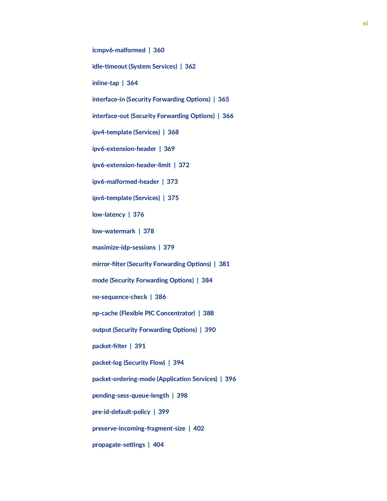
xi

icmpv6-malformed | 360


m

(System Services) | 362


inline-tap | 364


interface-in (Security Forwarding


ns) | 365

interface-out (Security Forwarding

ns) | 366

ipv4-template (Services) | 368


ipv6-extension-header | 369


ipv6-extension-header-limit | 372


ipv6-malformed-header | 373


ipv6-template (Services) | 375


low-latency | 376


low-watermark | 378


maximize-idp-sessions | 379


m rr r

r (Security Forwarding


ns) | 381

mode (Security Forwarding

ns) | 384

no-sequence-check | 386


np-cache (Flexible PIC Concentrator) | 388

output (Security Forwarding

ns) | 390

cr | 391

packet-log (Security Flow) | 394

packet-ordering-mode (

c n Services) | 396

pending-sess-queue-length | 398

pre-id-default-policy | 399


preserve-incoming-fragment-size | 402

r

s n s | 404


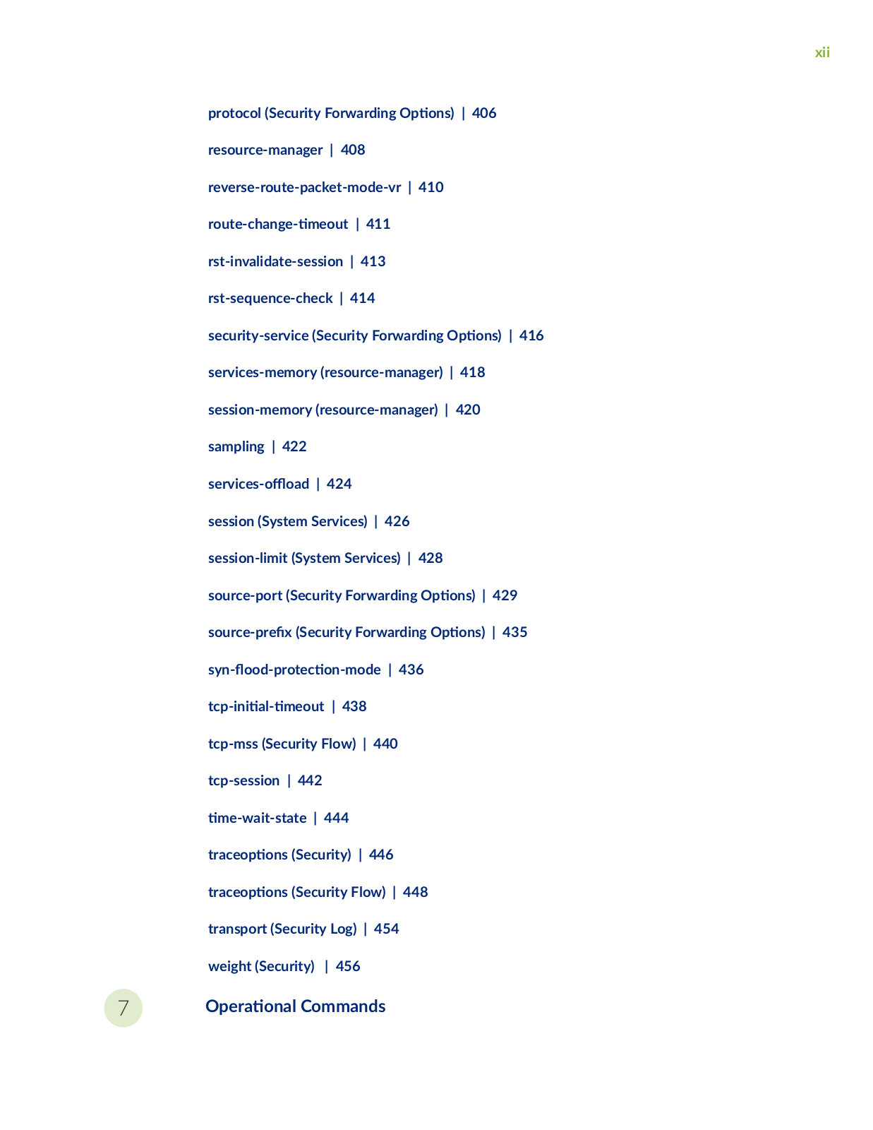
xii

protocol (Security Forwarding

ns) | 406

resource-manager | 408


reverse-route-packet-mode-vr | 410


r

c

n

m

| 411


rst-invalidate-session | 413


rst-sequence-check | 414


security-service (Security Forwarding

ns) | 416

services-memory (resource-manager) | 418

session-memory (resource-manager) | 420

sampling | 422


s

rv c s

ffl

|

424


session (System Services) | 426


session-limit (System Services) | 428


source-port (Security Forwarding


ns) | 429

s

rc

r x (Security Forwarding


ns) | 435

syn fl

r

c

n m

| 436


c

n

m


| 438


tcp-mss (Security Flow) | 440


tcp-session | 442


m w

s

| 444


r

c

ns (Security) | 446


r c

ns (Security Flow) | 448


transport (Security Log) | 454


weight (Security)

| 456


7

r n Commands

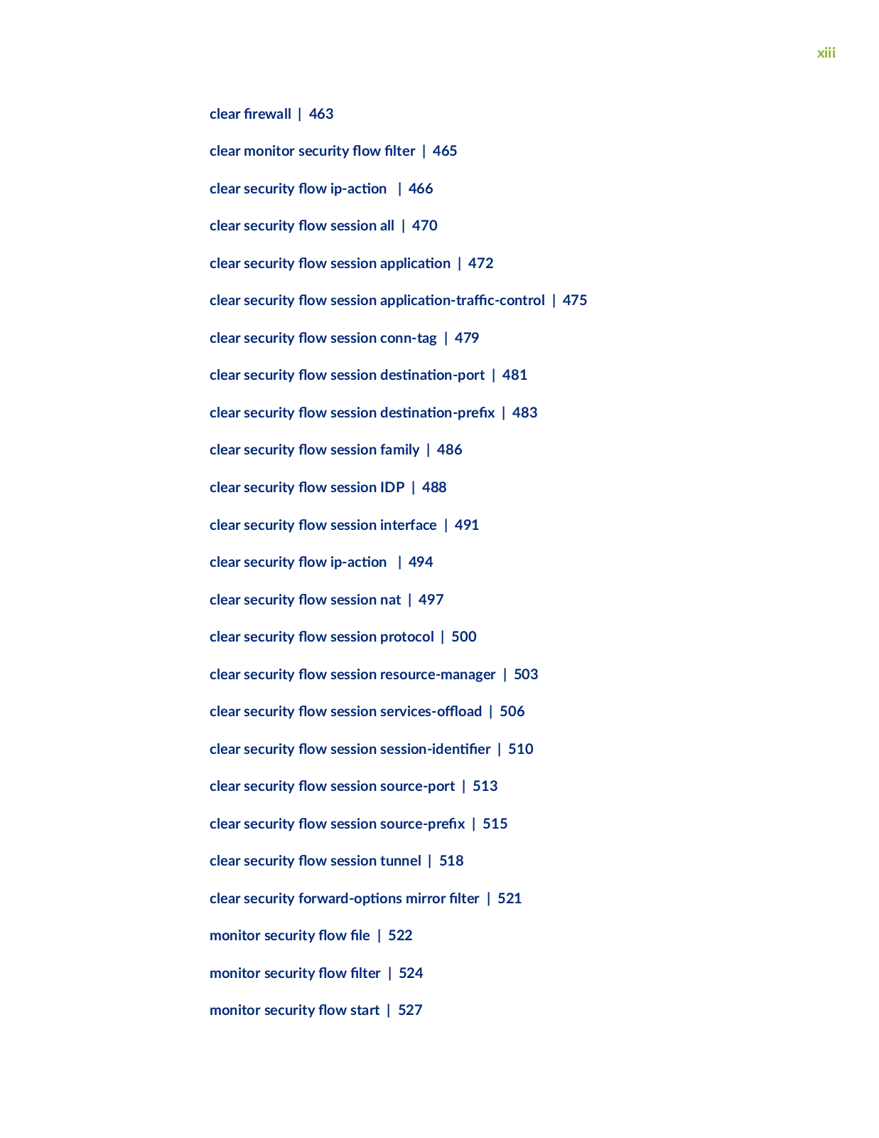
xiii

clear r w | 463


clear monitor security fl

w


r | 465


clear security fl

w

c

n

| 466


clear security fl

w session all | 470


clear security fl

w session


c


n | 472

clear security fl

w session


c


n

r

c c n r | 475

clear security fl

w session conn-tag | 479

clear security fl

w session

s

n


n


r | 481

clear security fl

w session

s

n


n

r

x | 483

clear security fl

w session family | 486


clear security fl

w session IDP | 488


clear security fl

w session interface | 491

clear security fl

w

c

n

| 494


clear security fl

w session nat | 497


clear security fl

w session protocol | 500

clear security fl

w session resource-manager | 503

clear security fl

w session s

rv c

s

ffl


| 506

clear security fl

w session s

ss

n

n


r | 510

clear security fl

w session source-port | 513

clear security fl

w session s

rc

r

x | 515

clear security fl

w session tunnel | 518


clear security

rw r


ns mirror


r | 521

monitor security fl

w

| 522


monitor security fl

w

r | 524


monitor security fl

w start | 527


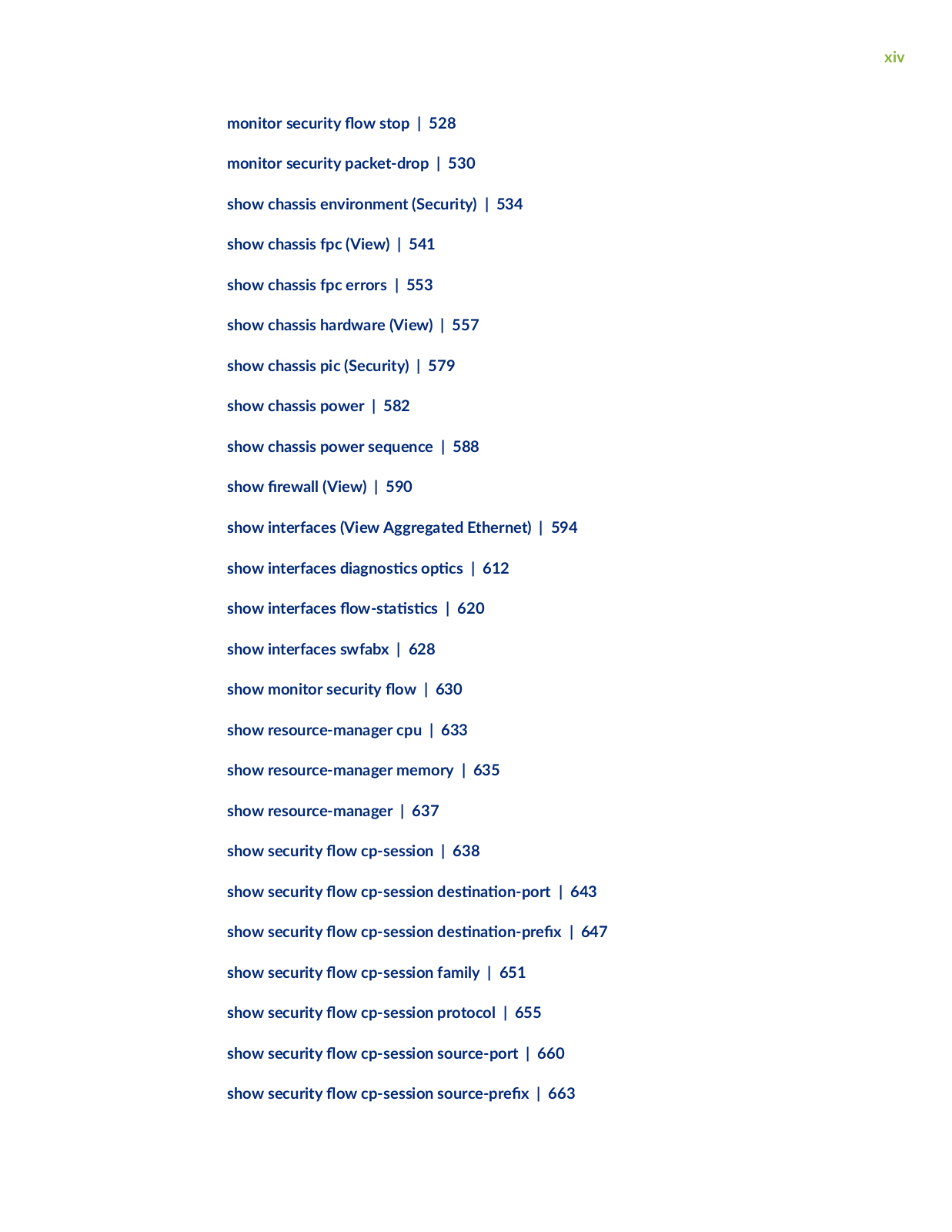
xiv

monitor security fl w stop | 528 monitor security packet-drop | 530

show chassis environment (Security) | 534 show chassis fpc (View) | 541

show chassis fpc errors | 553

show chassis hardware (View) | 557 show chassis pic (Security) | 579 show chassis power | 582

show chassis power sequence | 588 show r w (View) | 590

show interfaces (View Aggregated Ethernet) | 594

show interfaces

n s

cs

cs | 612


show interfaces fl w s

s cs | 620


show interfaces swfabx | 628


show monitor security fl

w | 630


show resource-manager cpu | 633


show resource-manager memory | 635


show resource-manager | 637


show security fl

w cp-session | 638


show security fl

w cp-session

s

n

n

r

| 643

show security fl

w cp-session

s

n

n

r

x | 647

show security fl

w cp-session family | 651


show security fl

w cp-session protocol | 655


show security fl

w cp-session source-port | 660

show security fl

w cp-session s

rc

r

x | 663

xv

show security fl

w gate | 667


show security fl

w

c

n | 674


show security fl

w gate brief node

| 686


show security fl

w gate

s

n

n


r

| 694

show security fl

w gate

s

n

n

r


x | 699

show security fl

w gate protocol | 704


show security fl w gate summary node

| 709

show security fl

w pmi s

s cs | 716


show security fl

w session | 720


show security fl

w session brief node

| 733

show security fl

w session


s

n

n


r

| 739

show security fl

w session


s

n

n


r

x | 745

show security fl

w session extensive node

| 752

show security fl

w session family | 761


show security fl

w session interface | 769


show security fl

w session nat | 776


show security fl

w session plugins | 781


show security fl

w session policy-id | 785


show security fl

w session


r

y | 791


show security fl

w session protocol | 795


show security fl

w session resource-manager | 803

show security fl

w session s

rv c s

ffl


| 809

show security fl

w session s

ss

n

n


r | 817

show security fl

w session source-port | 824

show security fl

w session s

rc

r

x | 830

xvi

show security fl

w session summary family | 836

show security fl

w session summary node

| 840


show security fl

w session summary s rv c s

ffl

| 849

show security fl

w session tunnel | 854


show security fl

w s

s

cs | 867


show security fl

w status | 874


show security

rw r

n

ns m rr r


r | 883

show security

rw r


ns resource-manager | 886

show security monitoring | 890


show security policies | 893


show security policies hit-count | 915


show security resource-manager group c

v

| 920

show security resource-manager resource

c

v

| 924

show security resource-manager s n s | 929


show security resource-manager summary | 932


show security screen

s

n | 934


show security screen s


s cs | 943


show security s

ftw r s | 959


show security zones | 962 show security zones type | 971

xvii

About This Guide

Use this guide to c n

r and monitor the fl w of r

c or packet, on a device using fl w b s

processing and packet-based forwarding. Also, for using an extensive set of fl w b s

security features

which include policies, screens, network address r ns

n (NAT), and other fl w b s

services.

Juniper Flow-Based and Packet-Based Processing User Manual

1

CHAPTER

Overview

r c Processing on SRX Series Devices Overview | 2

Central Point Architecture in Security Devices Overview | 38

2

rc Processing on SRX Series Devices Overview

IN THIS SECTION


Understanding

r

c Processing on Security Devices | 2


Understanding the Default Processing Behavior for IPv4 r c | 6


Understanding

r

c Processing on SRX210 and SRX320 Devices | 7


Understanding

r

c Processing on SRX3000 Line and SRX1400 Devices | 9


Understanding

r

c Processing on SRX4600 Devices | 14


Understanding

r

c Processing on SRX5000 Line Devices | 18


n r n IOC to NPC Mapping | 30

Understanding Flow Processing on SRX5K-SPC3 Devices | 31

Junos OS for security devices integrates network security and r

n

c b

s of Juniper Networks.

Packets that enter and exit a device undergo both packet-based and fl

w b s

processing.

Understanding r c Processing on Security Devices

IN THIS SECTION

Understanding Flow-Based Processing | 3

Understanding Packet-Based Processing | 5

Junos OS for security devices integrates the world-class network security and r

n c

b

s of

Juniper Networks. Junos OS includes a wide range of packet-based

r n

class-of-service (CoS)

c ss


rs and r c s

n features as well as a rich, extensive set of fl

w b s

security features

including policies, screens, network address r ns

n (NAT), and other fl

w b s

services.


r

c that enters and exits a security device is processed according to features you c n

r

such as

packet

rs security policies, and screens. For example, the s ftw r

can determine:


3

• Whether the packet is allowed into the device

• Which r w screens to apply to the packet

• The route the packet takes to reach its s n

n

Which CoS to apply to the packet, if any

Whether to apply NAT to translate the packet’s IP address

• Whether the packet requires an c n Layer Gateway (ALG)

Packets that enter and exit a device undergo both packet-based and fl w b s processing:

• Flow-based packet processing treats related packets, or a stream of packets, in the same way. Packet treatment depends on c r c r s cs that were established for the rs packet of the packet stream, which is referred to as a fl w

For the distributed processing architecture of the services gateway, all fl w b s processing occurs

on the SPU and sampling is m

r

aware. Packet sequencing is maintained for the sampled

packets.


Packet-based, or stateless, packet processing treats packets discretely. Each packet is assessed individually for treatment.

For the distributed processing architecture of the services gateway, some packet-based processing, such as r c shaping, occurs on the NPU. Some packet-based processing, such as c n of c ss rs to a packet, occurs on the SPU.

This topic includes the following s c ns

Understanding Flow-Based Processing

A packet undergoes fl

w b s processing

ft r packet-based

rs and some screens have been

applied to it. All fl w b

s processing for a single fl w occurs on a single Services Processing Unit

(SPU). An SPU processes the packets of a fl

w according to the security features and other services

c n

r for the session.


4

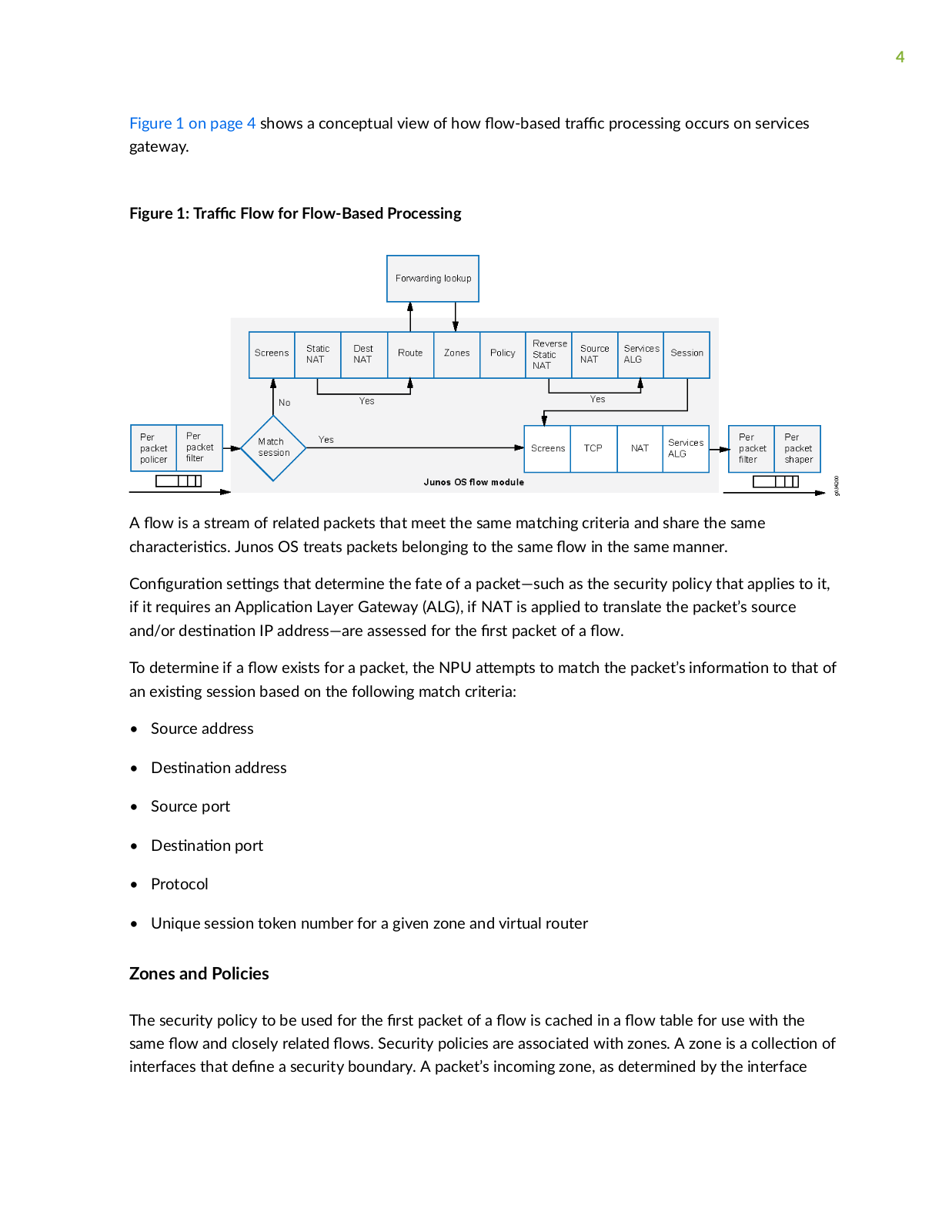
Figure 1 on page 4 shows a conceptual view of how fl w b s

r c processing occurs on services

gateway.


Figure 1:

r c Flow for Flow-Based Processing


A fl

w is a stream of related packets that meet the same matching criteria and share the same

c

r c

r s

cs Junos OS treats packets belonging to the same fl w in the same manner.


n

r

n s

n s that determine the fate of a packet—such as the security policy that applies to it,

if it requires an

c

n Layer Gateway (ALG), if NAT is applied to translate the packet’s source

and/or

s

n

n IP address—are assessed for the

rs packet of a fl w


To determine if a fl w exists for a packet, the NPU

m s to match the packet’s n rm

n to that of

an

x s

n session based on the following match criteria:


Source address

s n n address

Source port

s n n port

Protocol

Unique session token number for a given zone and virtual router

Zones and Policies

The security policy to be used for the rs packet of a fl w is cached in a fl w table for use with the same fl w and closely related fl ws Security policies are associated with zones. A zone is a c c n of interfaces that n a security boundary. A packet’s incoming zone, as determined by the interface

5

through which it arrived, and its outgoing zone, as determined by the forwarding lookup, together determine which policy is used for packets of the fl w

Flows and Sessions

Flow-based packet processing, which is stateful, requires the cr

n of sessions. A session is created

for the rs packet of a fl w for the following purposes:


To store most of the security measures to be applied to the packets of the fl w

To cache n rm

n about the state of the fl w


For example, logging and c n n n rm

n for a fl w is cached in its session. (Some stateful

rw screens rely on threshold values that pertain to individual sessions or across all sessions.)

To allocate required resources for the fl w for features such as NAT.

• To provide a framework for features such as ALGs and r w features.

Most packet processing occurs in the context of a fl w including:

• Management of policies, NAT, zones, and most screens.

• Management of ALGs and

n c n

Understanding Packet-Based Processing

A packet undergoes packet-based processing when it is removed from the queue on its input interface and before it is added to the queue on its output interface.

Packet-based processing applies stateless r w

rs CoS features, and some screens to discrete

packets.


• When a packet arrives at an interface, sanity checks, packet-based

rs some CoS features, and

some screens are applied to it.


• Before a packet leaves the device, any packet-based

rs some CoS features, and some screens

associated with the interface are applied to the packet.


Filters and CoS features are typically associated with one or more interfaces to nfl

nc

which packets

are allowed to transit the system and to apply special

c

ns to packets as necessary.


The following topics describe the kinds of packet-based features that you can c n

r

and apply to

transit r c


6

Stateless Firewall Filters

Also referred to as access control lists (ACLs), stateless

r w

rs control access and limit r

c

rates. They s c y evaluate the contents of packets

r ns n

the device from a source to a


s n

n or packets r

n

n

from or

s n

for the R

n Engine. A stateless

r w

r

evaluates every packet, including fragmented packets.


You can apply a stateless

r w


r to an input or output interface, or to both. A

r contains one or

more terms, and each term consists of two components—match c n

ns and c ns By default, a

packet that does not match a

r w

r is discarded.


You can plan and design stateless

r w


rs to be used for various purposes—for example, to limit

r c to certain protocols, IP source or

s

n

n addresses, or data rates. Stateless

r w

rs are

executed on the NPU.


Class-of-Service Features

CoS features allow you to classify and shape

r

c CoS features are executed on the NPU.


Behavior aggregate (BA) c

ss

rs—

s

c

ss rs operate on packets as they enter the device.


Using behavior aggregate c ss

rs the device aggregates

r n types of r

c into a single


forwarding class to receive the same forwarding treatment. BA c

ss

rs allow you to set the


forwarding class and loss priority of a packet based on the

r

n

Service (

S

rv) value.

r c shaping—You can shape

r c by assigning service levels with

r n delay,


r, and


packet loss c r c r s cs to

r c r


c

ns served by s


c

c r c fl

ws

r

c shaping is


especially useful for r

m

c

ns such as voice and video transmission.


Screens

Some screens, such as denial-of-service (DoS) screens, are applied to a packet outside the fl w process. They are executed on the Network Processing Unit (NPU).

Understanding the Default Processing Behavior for IPv4 r c

Flow-based processing mode is required for security features such as zones, screens, and r w policies to nc n By default, the SRX Series device is enabled for fl w b s forwarding for IPv4

rc on all devices, apart from the SRX300 Series and SRX550M devices that are set to drop mode.

S r n with Junos OS Release 15.1X49-D70 and Junos OS Release 17.3R1, for the SRX1500 series, SRX4100, SRX4200, SRX5400, SRX5600, SRX5800 and vSRX devices, you do not need to reboot the device when you are switching modes between fl w mode, packet mode, and drop mode. For SRX300

7

Series and SRX550M devices, you must reboot the device when switching between fl w mode, packet mode, and drop mode.

SRX300 Series and SRX550M

For the SRX300 Series and the SRX550M devices, the default processing mode is set to drop mode because of memory constraints. In this case, you must reboot the device ft r changing the processing mode from the drop mode default to fl w b s processing mode or packet-based processing mode— that is, between modes on these devices.

NOTE: For drop mode processing, the r c is dropped directly, it is not forwarded. It

rs

from packet-mode processing for which the r c is handled but no security processes are

applied.


C n r n an SRX Series Device as a Border Router


When an SRX Series device of any type is enabled for fl w b s processing or drop mode, to c n r

the device as a border router you must change the mode to packet-based processing for MPLS. In this

case, to c n r the SRX device to packet mode for MPLS, use the set security rw r n

ns

family mpls mode packet-based statement.


NOTE: As m n n previously, for SRX300 Series and the SRX550M devices, whenever you


change processing modes, you must reboot the device.


Understanding r c Processing on SRX210 and SRX320 Devices

IN THIS SECTION

Understanding Flow Processing and Session Management | 8

Understanding First-Packet Processing | 8

Understanding Session r n | 8

Understanding Fast-Path Processing | 9

8

This topic describes the process that the SRX210 and SRX320 Services Gateways undertake in establishing a session for packets belonging to a fl w that transits the device. The fl w services of the SRX210 and SRX320 devices are single-threaded and non-distributed. Although they r from the other SRX Series devices in this respect, the same fl w model is followed and the same command line interface (CLI) is implemented.

To illustrate session establishment and the packet “walk” including the points at which services are applied to the packets of a fl w the example described in the following s c ns uses the simple case of a unicast session:

Understanding Flow Processing and Session Management

This topic explains how a session is set up to process the packets composing a fl w In the following topic, the SPU refers to the data plane thread of the SRX210 or SRX320 Services Gateway.

At the outset, the data plane thread fetches the packet and performs basic sanity checks on it. Then it processes the packet for stateless rs and CoS c ss rs and applies some screens.

Understanding First-Packet Processing

To determine if a packet belongs to an x s n fl w the device

m s to match the packet’s

n

rm

n to that of an x s n session based on the following six match criteria:

Source address


s n

n address


Source port


s n

n port


Protocol

Unique token from a given zone and virtual router

The SPU checks its session table for an x s n session for the packet. If no existent session is found, the SPU sets up a session for the fl w If a session match is found, the session has already been created, so the SPU performs fast-path processing on the packet.

Understanding Session Cr n

In s n up the session, the SPU executes the following services for the packet:

Screens

Route lookup

9

Policy lookup

Service lookup

NAT, if required

ft r a session is set up, it is used for all packets belonging to the fl w Packets of a fl w are processed according to the parameters of its session. For the remainder of the steps entailed in packet processing, proceed to Step 1 in “Fast-Path Processing”. All packets undergo fast-path processing.

Understanding Fast-Path Processing

If a packet matches a session, Junos OS performs fast-path processing as described in the following steps. ft r a session has been set up for the rs packet in a fl w also undergoes fast-path processing. All packets undergo fast-path processing.

1. The SPU applies fl w b s security features to the packet.

• n r screens are applied.

TCP checks are performed.

Flow services, such as NAT, ALG, and IPsec are applied, if required.

2.The SPU prepares the packet for forwarding and transmits it.

• R

n packet

rs are applied.

r c shaping is applied.

• r c r r z n is applied.

r c scheduling is applied.

The packet is r nsm

Understanding r c Processing on SRX3000 Line and SRX1400 Devices

IN THIS SECTION

Components Involved in S n Up a Session | 10

Understanding the Data Path for Unicast Sessions | 11

10

Session Lookup and Packet Match Criteria | 11

Understanding Session r

n First Packet Processing | 12

Understanding Fast-Path Processing | 14

Junos OS for the SRX1400, SRX3400 and SRX3600 Services Gateways integrates the world-class


network security and r

n c b

s of Juniper networks. Junos OS for these service gateways

includes the wide range of security services including policies, screens, network address r ns

n

class-of-service c ss

rs and the rich, extensive set of fl w b s services that are also supported on

the other devices in the services gateways.


The distributed parallel processing architecture of the SRX1400, SRX3400 and SRX3600 devices includes m processors to manage sessions and run security and other services processing. This architecture provides greater fl x b y and allows for high throughput and fast performance.

The following s c ns describe the processing architecture using SRX3400 and SRX3600 devices as an example:

This topic includes the following n rm n

Components Involved in S n Up a Session

Here is an overview of the main components involved in s n up a session for a packet and processing the packets as they transit the SRX3400 and SRX3600 devices:

• Services Processing Units (SPUs)—The main processors of the SRX3400 and SRX3600 devices reside on Services Processing Cards (SPCs). They establish and manage r c fl ws and perform most of the packet processing on a packet as it transits the device. Each SPU maintains a hash table for fast

session lookup. The SPU performs all fl w b s processing for a packet, including

c

n of

security services, c ss rs and r c shapers. All packets that belong to the same fl

w are


processed by the same SPU.


The SPU maintains a session table with entries for all sessions that it established and whose packets it processes. When an SPU receives a packet from an NPU, it checks its session table to ensure that the packet belongs to it.

For SRX3400 and SRX3600 devices, one SPU acts in concert performing its regular session management and fl w processing nc ns and c n as a central point in which it arbitrates sessions and allocates resources. When an SPU performs in this manner it is said to be in combo mode.

11

Central Point—The central point is used to allocate session management to SPUs based on load balancing criteria. It distributes sessions in an intelligent way to avoid occurrences in which m SPUs might wrongly handle the same fl w The central point follows load balancing criteria in

c n

sessions to SPUs. If the session exists, the central point forwards packets for that fl w to

the SPU

s n it. It also redirects packets to the correct SPU in the event that the NPU fails to do

so.


For the SRX3400 and SRX3600 devices, one SPU always runs in what is referred to as combo mode in which it implements both the nc n y of the central point and the fl w and session management nc n y In combo mode, the SPU and the central point share the same loadbalancing thread (LBT) and packet-ordering thread (POT) infrastructure. .

• R

n Engine (RE)—The R

n Engine runs the control plane and manages the Control Plane

Processor (CPP).


Understanding the Data Path for Unicast Sessions

Junos OS for the SRX3400 and SRX3600 Services Gateways is a distributed parallel processing high throughput and high performance system. This topic describes the process of establishing a session for packets belonging to a fl w that transits the device.

To illustrate session establishment and the packet “walk” including the points at which services are applied to the packets of a fl w the following example uses the simple case of a unicast session. This packet “walk” brings together the packet-based processing and fl w b s processing that the Junos OS performs on the packet.

Session Lookup and Packet Match Criteria

To determine if a packet belongs to an x s n fl w the device

m s to match the packet’s

n

rm

n to that of an x s n session based on the following six match criteria:

Source address


s n

n address


Source port


s n

n port


Protocol

Unique token from a given zone and virtual router

12

Understanding Session Cr

n First Packet Processing


This topic explains how a session is set up to process the packets composing a fl

w To illustrate the

process, this topic uses an example with a source “a” and a s n

n “b”. The

r c

n from source to

s n n for the packets of the fl

w is referred to as (a -> b). The

r c n from

s n n to source

is referred to as (b -> a).


1.A packet arrives at an interface on the device and the IOC processes it.

The IOC dequeues the packet and sends it to the NPU with which it communicates.

2.The NPU receives the packet from the IOC and processes it.

• The NPU performs basic sanity checks on the packet and applies some screens c n r for the interface to the packet.

If a session match is found, the session has already been created on an SPU that was assigned to it, so the NPU forwards the packet to the SPU for processing along with the session ID.

Example: Packet (a ->b) arrives at NPU1 from IOC1. NPU1 performs sanity checks and applies DoS screens to the packet. NPU1 checks its session table for a tuple match and no x s n session is found. NPU1 forwards the packet to the central point on SPU1 for assignment to an SPU.

3. The central point creates a session with a “Pending” state.

The central point maintains a global session table that includes entries for all sessions that exist

across all SPUs on the device. It r c

s in session cr

n and delegates and arbitrates session

resources

c

n


This process entails the following parts:

a.The central point checks its session table and gate table to determine if a session or a gate exists for the packet it receives from the NPU. (An NPU has forwarded a packet to the central point

because its table indicates there is no session for it. The central point v r s this n rm

n

before

c n an SPU for the session.)


b.If there is no entry that matches the packet in either table, the central point creates a pending wing for the session and selects an SPU to be used for the session, based on its load-balancing algorithm.

c. The central point forwards the rs packet of the fl w to the selected SPU in a message telling it to set up a session locally to be used for the packet fl w

Example: The central point creates pending wing (a ->b) for the session. It selects SPU1 to be used for the session. It sends SPU1 the (a->b) packet along with a message to create a session for it. (It happens to be the case that SPU1 is the SPU that runs in combo mode. Therefore, its sessionmanagement and fl w r c ss n services are used for the session.

13

4. The SPU sets up the session.

Each SPU, too, has a session table, which contains n rm n about its sessions. When the SPU receives a message from the central point to set up a session, it checks its session table to ensure that a session does not already exist for the packet.

a. If there is no x s n session for the packet, the SPU sets up the session locally.

b. The SPU sends a message to the central point, telling it to install the session.

During rs

c

processing, if NAT is enabled, the SPU allocates IP address resources for NAT. In

this case, the

rs

c processing for the session is suspended n the NAT

c

n process is

completed.


The SPU adds to the queue any

n packets for the fl w that it might receive

n

the session

has been installed.


Example: SPU1 creates the session for (a ->b) and sends a message back to the central point (implemented on the same SPU) telling it to install the pending session.

5. The central point installs the session.

It sets the state for the session’s pending wing to

c

v

It installs the reverse wing for the session as an c

v

wing.

It sends an ACK (acknowledge) message to the SPU, n c n that the session is installed.

Example: The central point receives a message from SPU1 to install the session for (a->b). It sets the session state for (a->b) wing to c v It installs the reverse wing (b->a) for the session and makes it

c v this allows for delivery of packets from the reverse r c n of the fl w s n

n (b) to be

delivered to the source (a).


6. The SPU sets up the session on the ingress and egress NPUs.


NPUs maintain n rm n about a session for packet forwarding and delivery. Session n rm n is set up on the egress and ingress NPUs (which s m m s are the same) so that packets can be sent directly to the SPU that manages their fl ws and not to the central point for r r c n

7.Fast-path processing takes place.

For the remainder of the steps entailed in packet processing, proceed to Step 1 in “Understanding Fast-Path Processing”.

Loading...
+ 963 hidden pages