

Page 1

Page 2

ActiveSync, Excel, Hotmail, Internet Explorer, Microso, MSN,
Outlook, PowerPoint, Visual Studio, Windows, Windows
Media, Windows Mobile, Windows Mobile Device Center,
Windows Vista, and the Windows logo are trademarks or
registered trademarks of Microso Corporation in the United
States and/or other countries.
The Bluetooth
®
word mark is owned by the Bluetooth SIG, Inc.
and any use of such marks by Juniper Systems, Inc. is under
license.
Acrobat and Reader are registered trademarks of Adobe Systems
Incorporated in the United States and/or other countries.
The names of actual companies and products mentioned herein
may be the trademarks of their respective owners.
© Copyright 06-2008 Juniper Systems, Inc. All rights reserved.
P/N 20020-02
WARNING! Text set o in this manner indicates that
failure to follow directions could result in serious injury.
CAUTION: Text set o in this manner indicates that failure to
follow directions could result in damage to equipment or loss
of information.
!!
!!
Page 3

Contents
1 Getting Started
The Anatomy of the Field PC 6
Getting Started 7
2 Battery and Power
Battery Settings Screen 12
Charging the Battery Pack 14
USB/Power Dock 16
Using Vehicle Power 18
3 Communicating with a
Desktop Computer
Communicating with a Desktop Computer 20
4 Using the Hardware
Using the Hardware 24
Powering Off, Suspending, Resetting, and
Restoring Factory Defaults 26
Using the stylus 28
Using the Touchscreen 29
PC Card Installation 30
Micro SD Card Installation 30
5 Programs and Settings
Understanding the Today Screen 34
Entering Information 35
Recognizing Status Icons 37
Recognizing Soft Keys 38
Performing Common tasks on the Field PC 40
Contents iii
Page 4

iv Field PC Owner’s Manual
Using On-Device Help 43
Backing Up Data 44
Connecting to a Desktop Computer 48
Information for Software Developers 48
6 Bluetooth® Wireless Communications
Bluetooth® Drivers and Profiles 50
Supported Bluetooth® Profiles 56
7 Wi-Fi Connections
Wi-Fi Connections 64
8 Care and Maintenance
Caring for Your Field PC 68
Disposing of the Field PC and Battery Pack 73
9 Service Information
Repairing the Field PC 76
Preparing for a Service Center Call 76
A Product Specifications and Warnings
Product Specifications 78
Battery Warnings 79
Equipment Warnings 80
B Certifications and
Regulatory Information
Regulatory Information 82
Limited Product Warranty 85
Index
Page 5
1
Getting Started
6 The Anatomy of the Field PC
7 Getting S
tarted
Page 6
6 Field PC Owner’s Manual
The Field PC is a rugged handheld computer designed for
data collection from multiple environments. Equipped with
Windows Mobile 6 it features a wide variety of applications
soware and accessories.
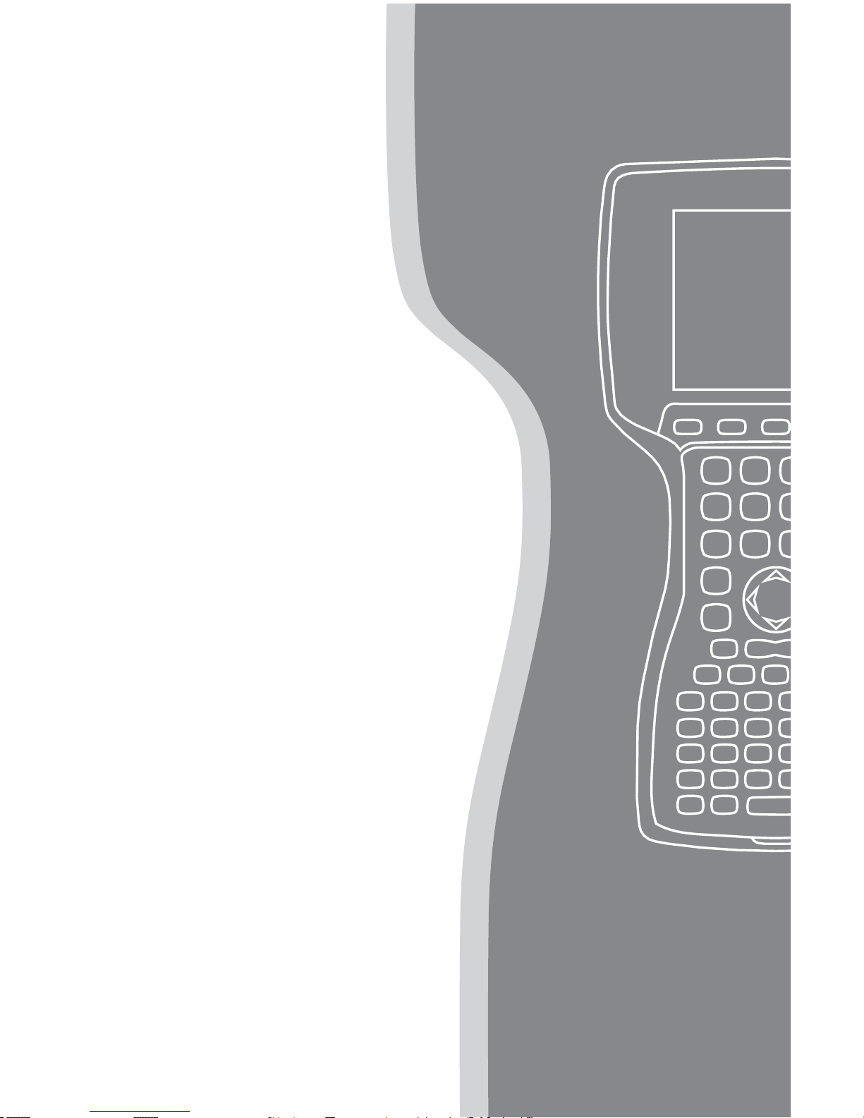
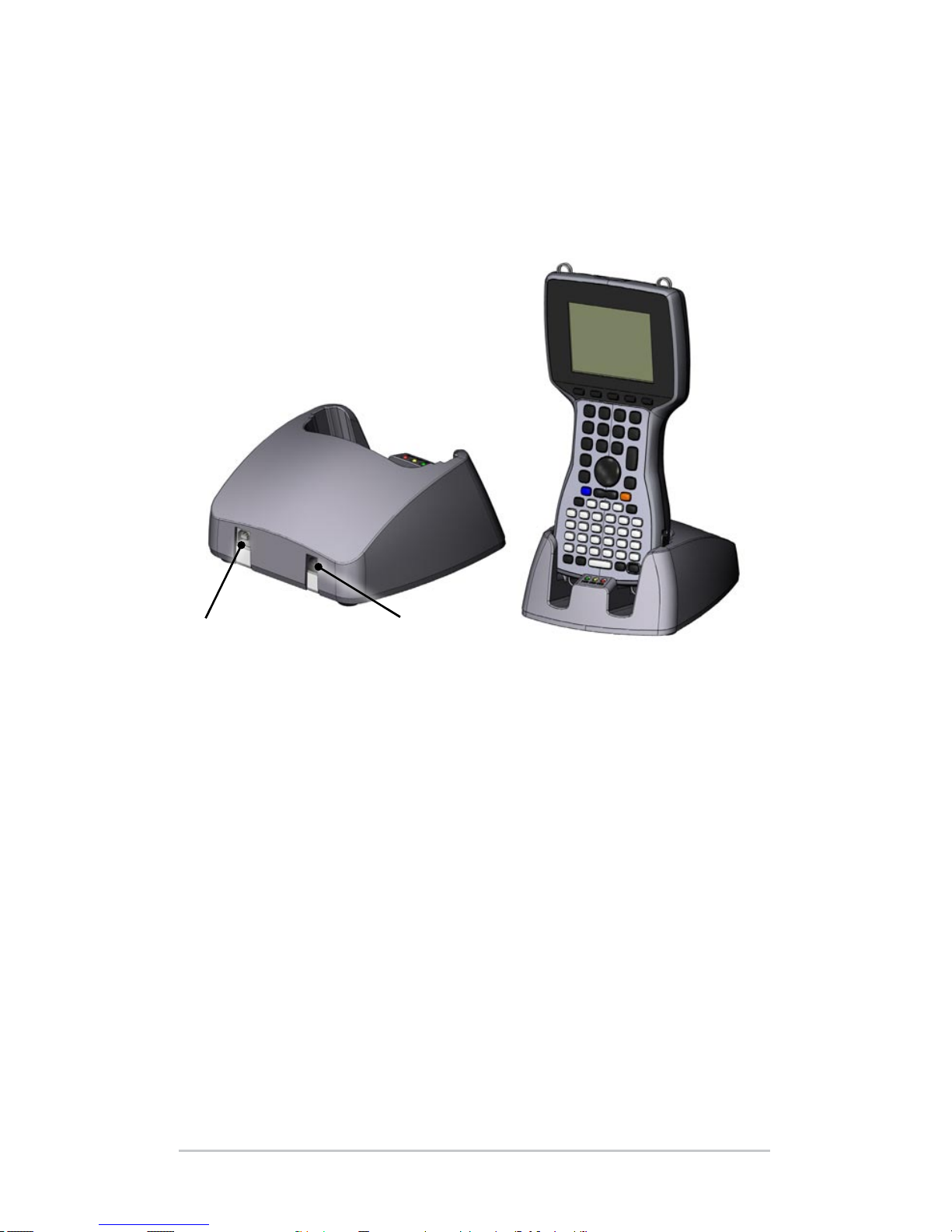
The Anatomy of the Field PC
The picture below shows some of the important features of the
Field PC.
8
1
2
3
4
5
7
9
10
11
CAUTION: Tampering
with the jack screws will
break the waterproof
seal of the unit.
!!
6
USB client (mini B)
Touchscreen/display
Top lanyard cleats
Battery door latches
Power button
Bottom lanyard cleats
7
8
9
10
USB host (full size A)
12V DC jack
Stylus
9-pin serial port
1
2
3
4
5
6
11
Back compartment door
Page 7
Getting Started
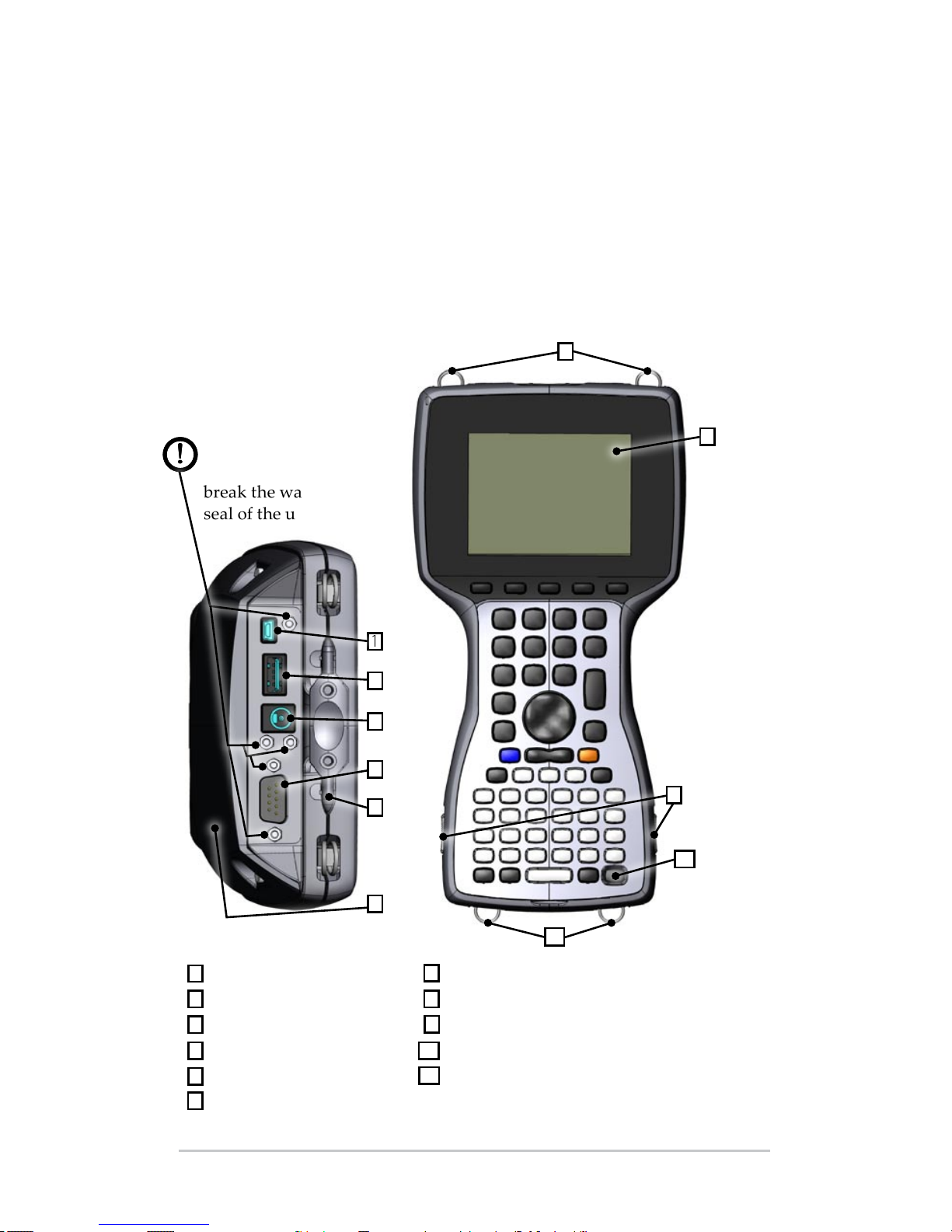
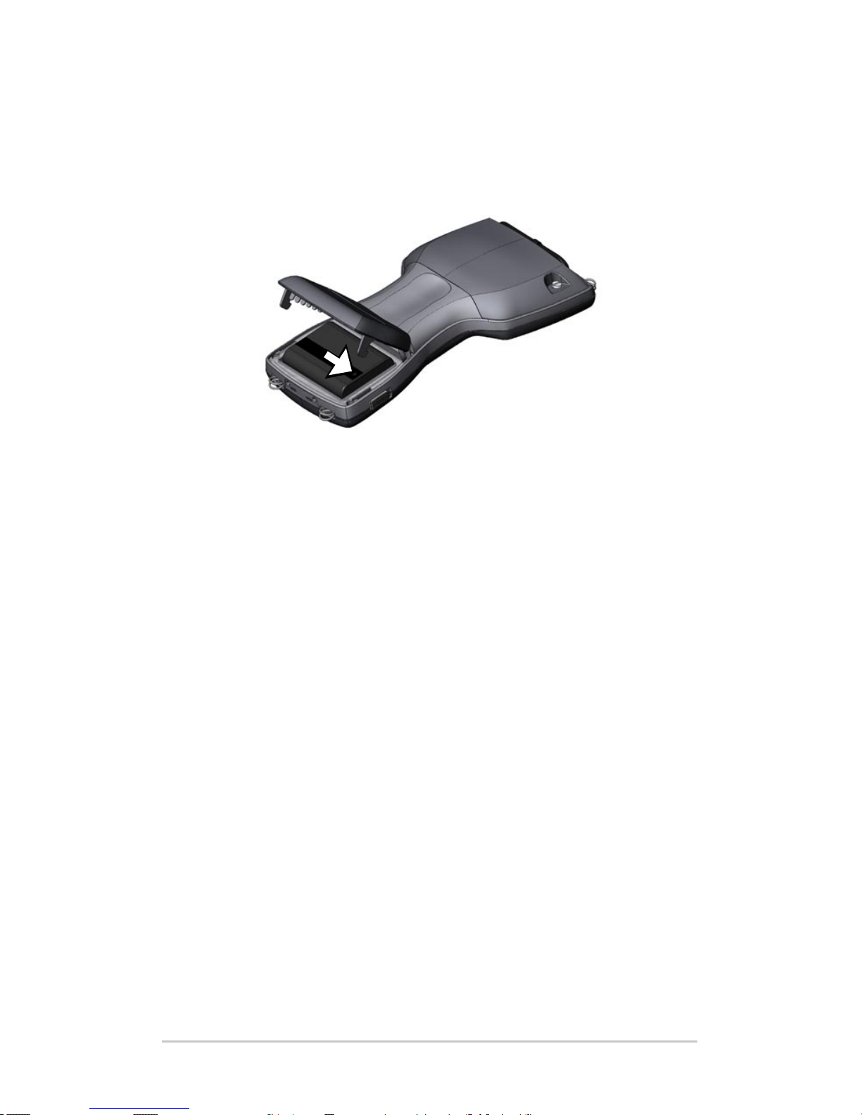
Install the Battery Pack
When you receive the Field PC, you must install and charge
the NiMH baery pack before using. To do this, complete the
following steps:
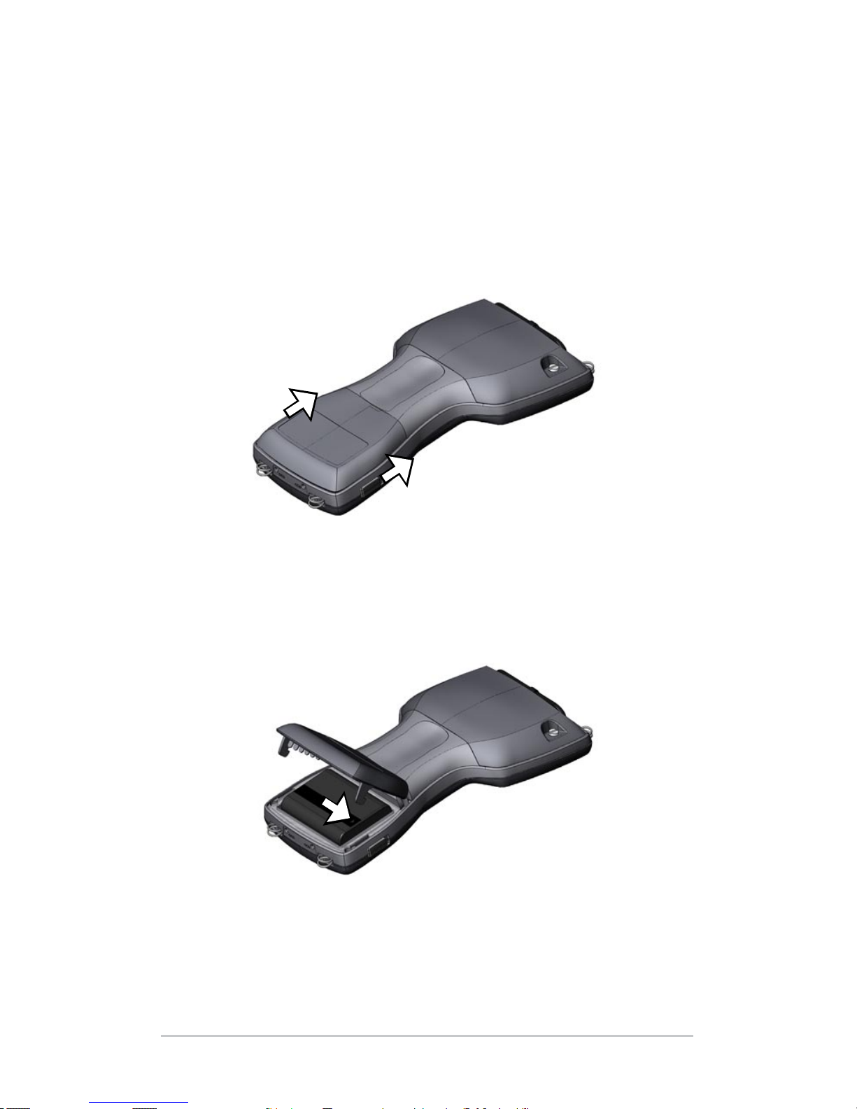
1. Push up on the sliding latches on the sides of the Field PC
t
o open the baery compartment door.
2. Place the NiMH baery pack in the le side of the baery
co
mpartment, push down, and slide it all the way to the
right. There is a small arrow on the boom right corner of
the baery pack, make sure the arrow is pointing to the
ri
ght when it is placed in the Field PC.
Ch 1 Getting Started 7
Page 8
8 Field PC Owner’s Manual
3. Push the baery door closed until the slide latches click
into place. If the latches are not securely in place the unit is
no longer water tight.
N
ote: Do not turn on the Field PC yet.
4. Plug the AC wall charger that came with the Field PC into
t
he wall socket.
5. Remove the rubber protector from the Field PC’s external
p
ower input jack.
Page 9
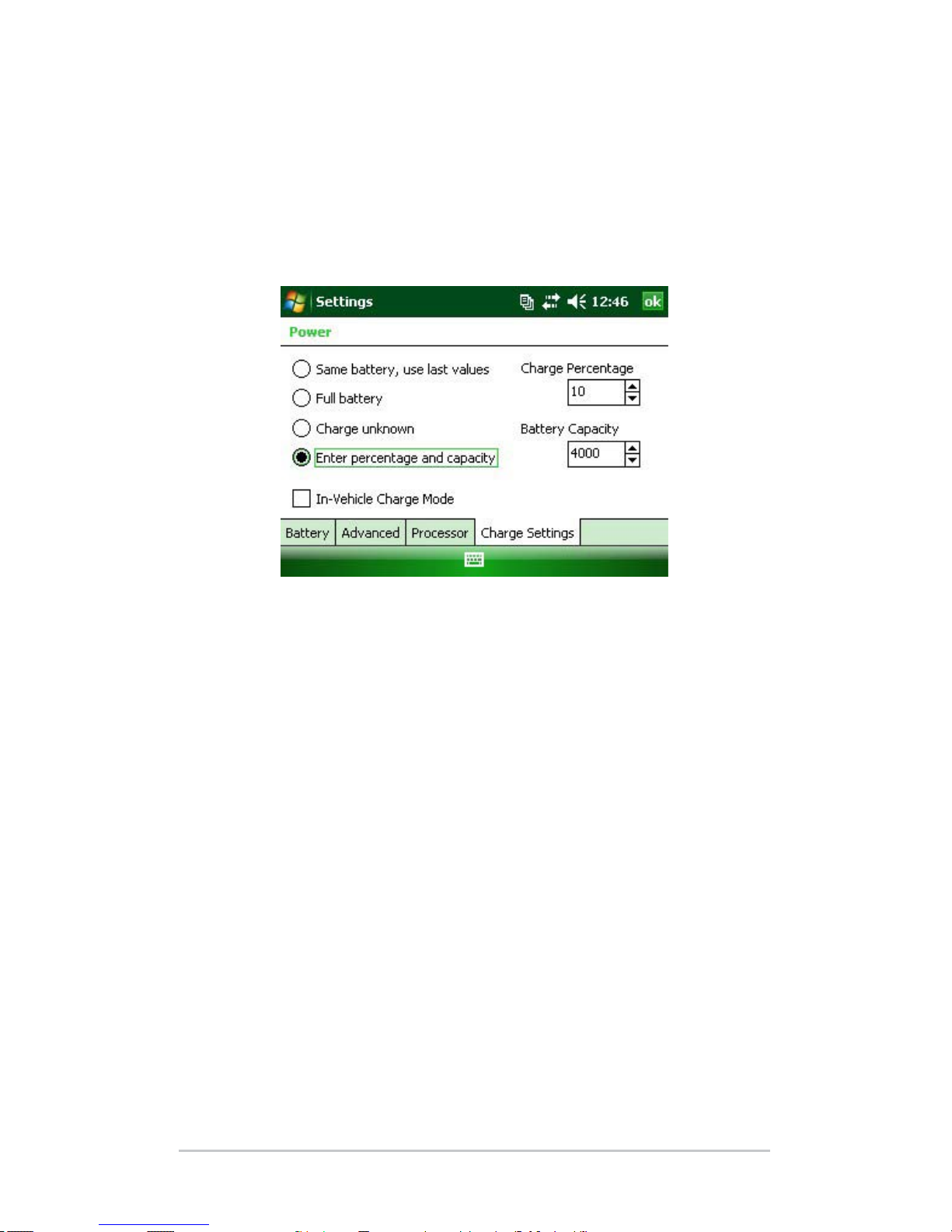
6. Plug the wall charger into the Field PC power jack located
at the top of the case. The Charge Seings screen opens
requesting you set the charge percentage. Select En
ter
percentage and capacity, set the baery charge to 10%, and
leave the baery capacity at 4000.
7. Charge the baery pack at room temperature for at least
6 h
ours.
Ch 1 Getting Started 9
Page 10

10 Field PC Owner’s Manual
Page 11

2
Battery and
Power
12 Battery Settings Screen
14 C
harging the Battery Pack
16 U
SB/Power Dock
18 U
sing Vehicle Power
Page 12
12 Field PC Owner’s Manual
This chapter teaches you about the rechargeable NiMH baery
pack. It typically lasts 12 to 20 hours, and charges in 4–6
hours using a wall charger, vehicle charger (optional), or USB/
PowerDock (optional).
Battery Settings Screen
Understanding the Battery Settings Screen
The baery charge percentage of the Field PC must be
conrmed or manually set using the Baery Seings Screen.
This screen appears whenever:
The baery pack is removed and (re)installed.
The “Power O” option is selected from the “Power Buon”
menu (which appears aer holding the Power Buon for 8
seconds) and then the Field PC is powered back on.
A Hard Reset is performed (by holding down the Power
Buon for 10 seconds).
A Clean Boot (Set to Factory Defaults) is performed.
The charge of the baery pack is fully drained while in
the Field PC, and the unit is then plugged into an AC wall
charger or USB/Power Dock and turns on.
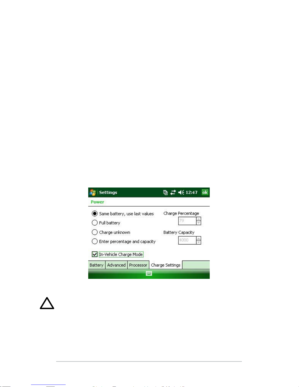
Note: To access the Charge Seings screen, you can either tap the
baery icon or go to Start > Seings > System tab > Power >
Charge Seings tab.
Page 13

Battery Settings Options
The New Baery Detected screen has four choices:
Same baery, use last values
Full baery
Charge unknown
Enter percentage and capacity
Use Same Baery if t
he Field PC was turned o and back
on or if the baery was taken out and re-inserted without
being recharged, this option uses the information the
unit already has for the baery seing.
Use Full Baery if the baery is fully charged.
Use Charge Unknown if you do not know the charge of the
baery.
Note: The baery gauging will not be accurate with Charge
Unknown until the baery is fully charged. The baery icon
may not display the percentage of charge correctly.
Use Enter percentage and capacity if you know the charge or
if it is a new baery pack.
Ch 2 Battery and Power 13
Page 14

14 Field PC Owner’s Manual
Enter the correct percentage if it is known and click Ok. If it is a
new baery pack complete the following steps:
1. Set the Percentage to 10 and leave the Baery Capacity
a
t 4000.
N
ote: The factory baery is 4000 mAh and so the default for the
Capacity box is 4000. To learn more about this seing read the
Baery Capacity section.
2. Tap on Ok to save the seings and to close the screen.
3
. Plug unit into AC charger to charge the new baery.
O
nce the baery pack is fully charged, the gauging is
automatically set to 100%.
B
a
ttery Capacity
The capacity is the amount of energy a fully charged baery can
supply in milliamp-hours (mAh). The baery capacity of the
factory Field PC baery pack is 4000 so the default seing for the
baery capacity is 4000.
If you are using a dierent baery pack, check its mAh
rating commonly listed on the baery label. For optimum
performance, use baery packs with a 3000 to 4000 mAh
capacity. The higher the capacity the longer the charge is held.
Note: As a baery pack ages, operation time is reduced. The capacity
seing for an older baery pack can be adjusted downward to reduce
charging time and to more accurately represent the baery capacity.
Charging the Battery Pack
Recharging the NiMH Battery Pack
We recommend charging the Field PC baery pack when it is
not in use. The Field PC prevents the baery pack from being
overcharged if le plugged into the wall charger.
Page 15
Temperature Ranges for Charging the NiMH Battery Pack
The Field PC NiMH baery pack is charged most eciently at
temperatures ranging between 10° to 20° C (50° to 68° F) when
th
e AC power adapter is used. The Field PC baery pack does
not charge outside of the range 0° to 40° C (32° to 104° F).
Us
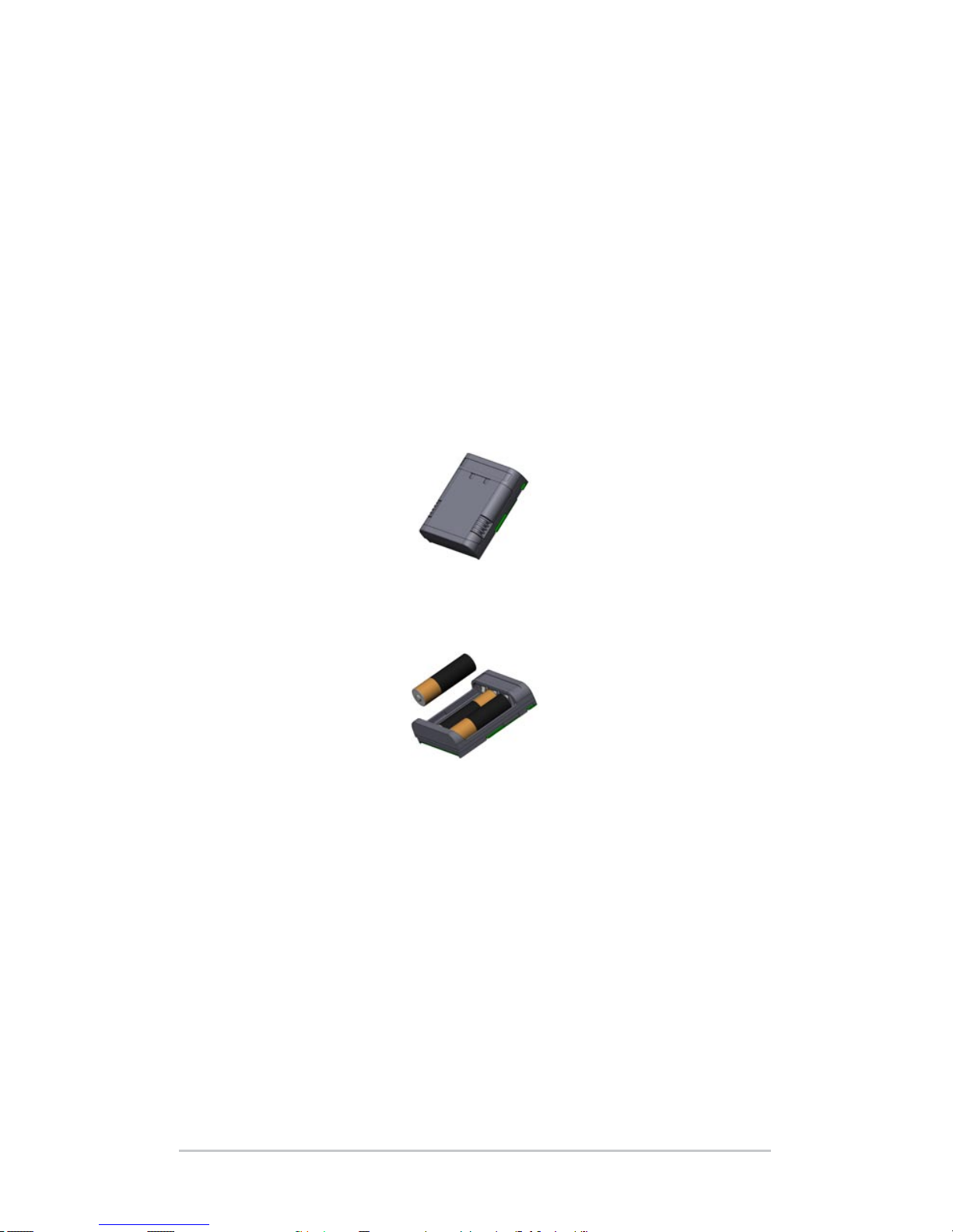
ing the Alkaline Battery Holder (optional accessory)
To properly use the alkaline baery holder, complete the
following steps:
1. Open the alkaline baery holder by pressing the tabs
s
imultaneously on either side and pulling.
2. Insert three unused AA alkaline baeries by following the
+ a
nd – signs respectively.
N
ote: It is important that only alkaline baeries are used. We
recommend using non-rechargeable high quality alkaline baeries
su
ch as Duracell
®
Ultra or Energizer® Lithium.
3. Close the alkaline baery holder by sliding the door in
p
lace and press down to snap it securely shut.
Ch 2 Battery and Power 15
Page 16
16 Field PC Owner’s Manual
4. Follow the directions for changing a baery pack to install
the alkaline baery holder. However, the charge seings
screen will not pop up.
The alkaline baery holder is to be used as an emergency,
secondary source of power, not as the primary source. The
baeries do not last as long as the standard baery pack and
have a lower performance rate. The display heater cannot be
enabled and the backlight is disabled when the baery power
level is low.
Please recycle used alkaline baeries in a responsible way.
USB/Power Dock
The USB/Power Dock charges the Field PC, and allows you
to transfer and synchronize les between the Field PC and
a desktop computer. The Power Dock is ordered separately.
Listed below are the functions of the three LED indicators on
the Power Dock:
Function LED Color
Power Supply Green
Charging Amber
USB Communication Red
Page 17
Power Supply
The Power Dock uses the AC wall adapter that comes with the
Fi
eld PC. Plug the Field PC power adapter into the dock, in the
back on the right, and then into the wall.
When the green LED indicator turns on, the Power Dock has
power.
Charging
Th
e Power Dock charges the Field PC. Place the Field PC into
the Power Dock and the Field PC automatically turns on and
begins charging, the amber LED is on. When the amber LED
tu
rns o, the Field PC is nished charging. The charging time
is the same whether the Field PC is turned on or o.
Note: Never operate the Field PC in the USB/Power Dock without
a baery installed. The dock does not supply adequate power to the
Fi
eld PC for normal operation. Do not use the Power Dock with
alkaline baeries installed.
USB Client (USB-B)
12V DC jack
USB Client (USB-B)
12V DC jack
Ch 2 Battery and Power 17
Page 18
18 Field PC Owner’s Manual
USB Communication
T
he Power Dock also provides a USB connection from the
Fi
eld PC to the desktop computer. The red LED indicator turns
on when the USB connection between the Field PC and desktop
computer is active.
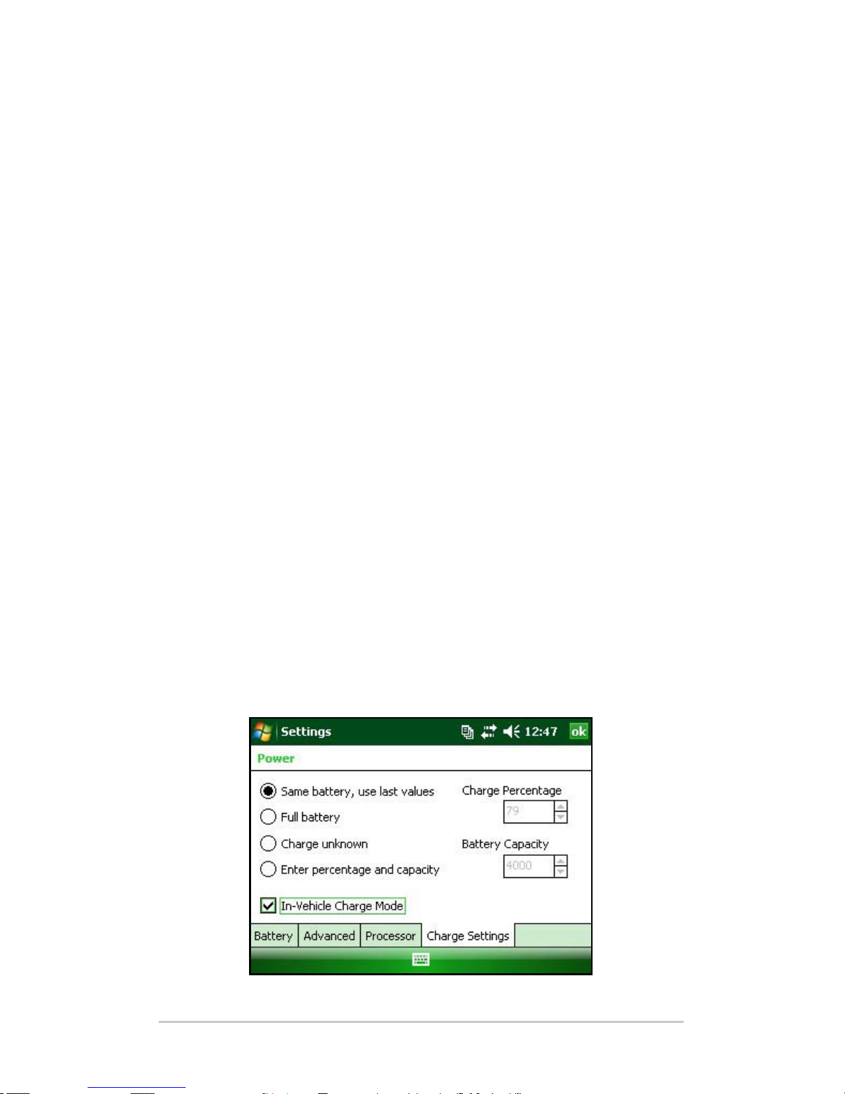
Using Vehicle Power
Vehicle Mode should be used when the Field PC is connected
to a vehicle power supply. By using Vehicle Mode the
baery does not charge if the charge level is above 90%. This
restriction makes sure the baery is not overcharged.
To turn Vehicle Mode on (default is o), complete the following
steps:
1. T
ap S
tart > Seings > System tab > Power > Charge Seings tab.
2. Sele
ct In-Vehicle Charge Mode check box.
3. Tap o
k.
WARNING: If Vehicle Mode is not used when charging in a
vehicle, the baery may be overcharged resulting in permanent
damage to the baery.
!!
Page 19

3
Communicating
with a Desktop
Computer
20 Communicating with a
Desktop Computer
Page 20
20 Field PC Owner’s Manual
The Field PC can connect to a desktop computer using
either ActiveSync
®
(for computers with Windows® 2000 and
Windows
®
XP), or Windows Mobile® Device Center (for
computers with Windows Vista™).
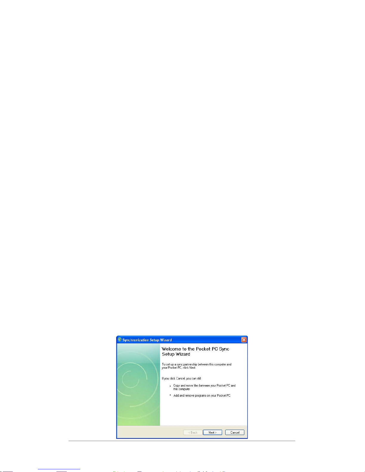
Communicating with a Desktop Computer
Install ActiveSync® on a Desktop Computer (Windows® 2000 and
Windows® XP)
Note: If you have Windows
Vista™, see Install Windows Mobile
Device
®
Center.
Insert the Geing Started Disc into your desktop computer. A
window appears on the display.
Select your language.
Follow the directions on the screen to install Windows
®
ActiveSync
®
4.5.
Note: Install ActiveSync® before aaching the USB cable to the
de
sktop or Field PC.
Creating an ActiveSync® Connection
1. Plug USB Client end (mini B) of the USB communications
c
able into your Field PC.
2. Plug the USB Host end (full size A) of the USB
co
mmunications cable into your desktop computer.
3. Establish an ActiveSync® p
artnership by following the
instructions on the desktop computer screen.
Page 21
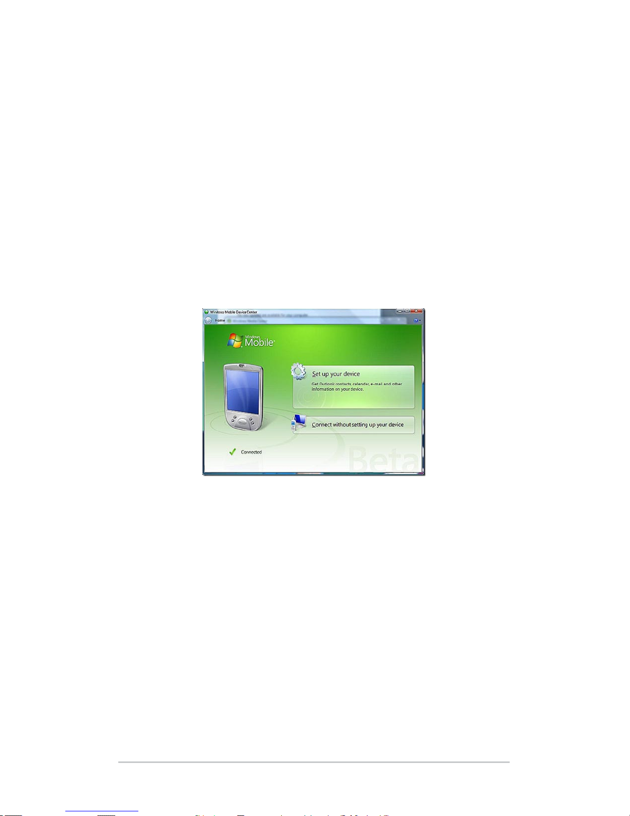
Install Windows Mobile® Device Center on a Desktop Computer
(Windows Vista™)
To install the Windows Mobile® Device Center on a desktop
computer with Windows Vista™ complete the following steps:
1. C
onnect your device to your desktop computer.
2
. Download the Windows Mobile® D
evice Center Installer
to your computer by clicking on the download link that
appears in the pop-up window.
3. Select “Run this program from its current location” and
click OK.
4. Follow the instructions on the screen.
C
reating Windows Mobile® Device Center Connection
Once Windows Mobile® Device Center has been installed,
create a connection at any time by plugging one end of a USB
ca
ble into the computer and the other end into the Field PC.
Windows Mobile® Device Center automatically opens. Follow
the steps on the screen.
Note: For more information about connecting to a computer using
either ActiveSync® or Windows Mobile® D
evice center visit the
Microso Windows Mobile® website.
Ch 3 Communicating with a Desktop Computer 21
Page 22

22 Field PC Owner’s Manual
Page 23

4
Using the
Hardware
24 Using the Hardware
26 P
owering Off, Suspending, Resetting,
and Restoring Factory Defaults
28
U
sing the Stylus
29 U
sing the Touchscreen
30 P
C Card Installation
30 M
icro SD Card Installation
Page 24
24 Field PC Owner’s Manual
This chapter discusses the hardware components of the Field
PC. Specically, you will learn about:
Keyboard functions
Suspending, powering o, and reseing the device
Using the stylus
Using the touchscreen
Using the PC card slot
Using the Micro SD card slot
Using the Hardware
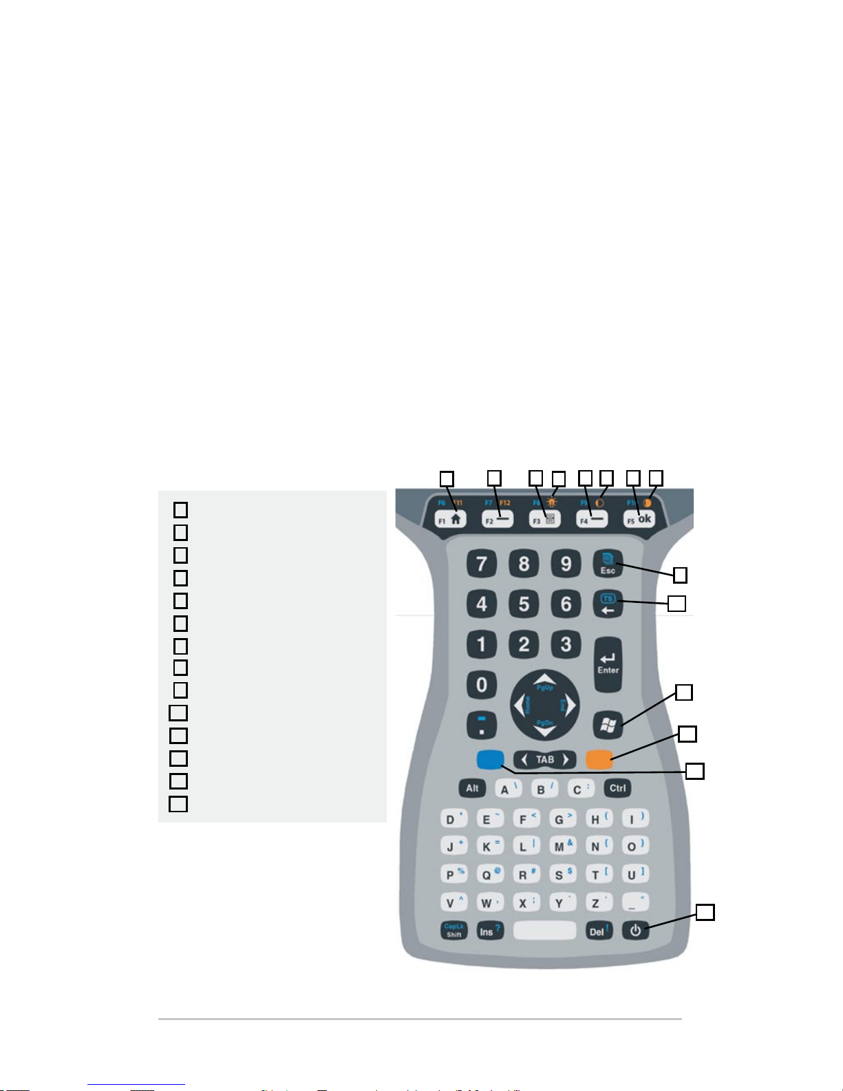
Keyboard Features
Pictured below is a diagram of the Field PC keyboard.
1
2 3
4
5 76 8
9
10
11
12
13
14
Home
Left soft key
Menu
Right soft key
OK
Backlight
Contrast/Brightness dim
Contrast/Brightness bright
Orange shift key
Blue shift key
Tasks manager
Touchscreen enable/disable
Windows start menu
Power
1
2
3
4
5
6
7
8
9
10
11
12
13
14
Page 25

Some keys have standard functions as well as special functions
accessed with the ORANGE and BLUE shi keys.
Five keys are located below the display. These keys act as
standard Windows Mobile keys unless the application program
uses them as function keys. With the use of the ORANGE
and BLUE shi keys, twelve function keys and three special
function keys are available.
Function Keys and Key Sequences
The Windows Mobile functions are the standard key outputs.
These include the Home key, the Menu key, and the Tasks
Manager key. The standard key outputs are functional unless
an ORANGE or BLUE shi key is pressed.
S
hi
ft Key Usage
Note: Follow the same steps with the ORANGE shi key to access the
orange printed keyboard characters.
To access a single blue printed keyboard characters:
Press and release the BLUE shi key followed by the key
with the desired blue-leered character.
To activate several blue-leered keys before returning to
standard mode:
Press and hold the BLUE shi key down while you press all
the desired BLUE keys. Once the BLUE shi key is released,
the keyboard reverts back to the standard mode.
Co
mmunication Ports
The Field PC has the following communication ports located at
the top of the case:
9 pin serial port
USB A (host) port
USB B mini (client) port
Ch 4 Using the Hardware 25
Page 26
26 Field PC Owner’s Manual
Connector Protectors
The Field PC is sealed without the protectors, however the rubber
connector protectors keep dirt and moisture out of the ports.
Powering Off, Suspending, Resetting, and Restoring
Factory Defaults
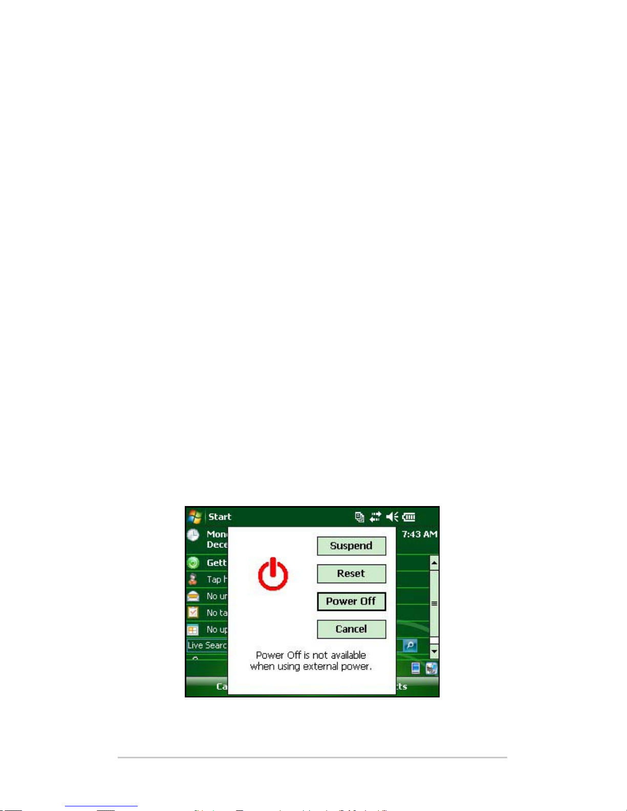
The Power buon allows you to suspend, power o, or reset
the device. A series of keyboard actions also lets you restore
seings, and icons to their original factory defaults. Below are
instructions for each action.
Po
wering Off the Device
When the device is powered o, it closes all programs and
powers down all system components except for the real-time
clock. Unlike suspend mode, the device resets when it is
powered on again. Any unsaved data will be lost.
To preserve baery power, we recommend you power o the
device if it will be le unused for two weeks or longer.
To p
ower o the Field PC,
1. Save all open les and close any running programs.
2
. Press and hold the Power buon until the Power Buon
m
enu appears.
N
ote: The Field PC cannot be powered o while it is plugged into
the wall charger.
Page 27
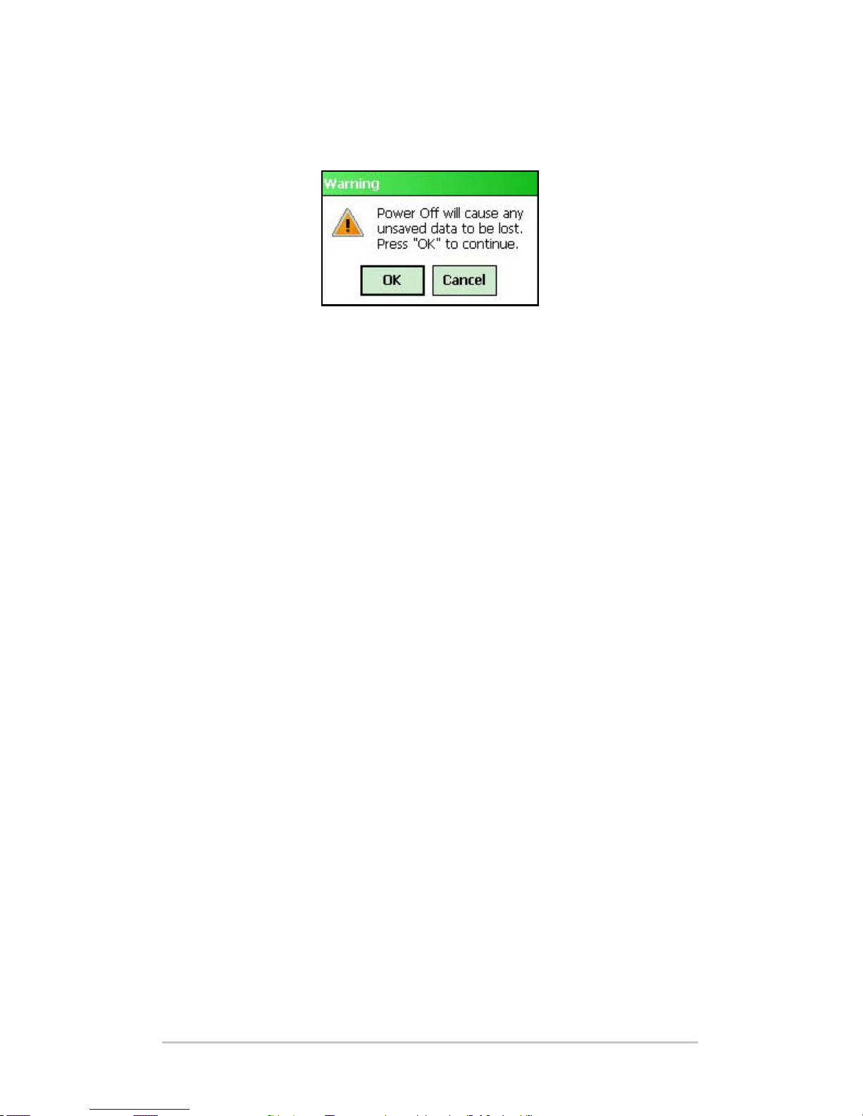
3. Tap Power O. A warning dialog appears. Tap OK.
To power on your Field PC, hold down the Power buon until
you see the screen light up.
Note: The Baery Seings screen will appear when you power on
yo
ur Field PC.
Suspending th
e Device
Suspending the Field PC is dierent from powering it o.
When the device is suspended it goes to sleep, and when it is
turned back on, the device resumes where it was before it was
suspended. Some baery power is used during suspend.
We recommend suspending your device if you plan to turn it
o for less than two weeks as long as the Field PC is aached to
wall charger every night and weekend.
To suspend your device, press the Power buon briey and
release. To resume the device from suspend mode, press the
Power buon again.
Re
setting the Device
Follow the steps below to reset the Field PC:
1. Save your open les and close any running programs.
2
. Press and hold the Power buon until the Power Buon
m
enu appears.
3. Choose R
eset.
If your device locks up, you can reset the device by pressing
the Power buon for 10 seconds or until the screen goes dark.
Aer a few seconds, the device turns on again.
Ch 4 Using the Hardware 27
Page 28

28 Field PC Owner’s Manual
Restoring the Device to its Factory State
Follow the steps below to restore user storage, seings, and
ico
ns on your Field PC to their original factory defaults.
CAUTION: Restoring the Field PC to its original factory state
permanently erases data saved on the Field PC, any soware
you installed, and any changes you made to the Field PC
(including seings changes).
To perform a clean boot, which restores everything but the
“storage” folder, select Reset from the Power Buon menu and
immediately press and hold Ctrl + Alt + Del.
To perform a storage clean, which cleans the “storage” folder,
select Reset from the Power Buon menu and immediately
press and hold down Ctrl + Alt + 2.
Perform both a clean boot and a storage clean for a complete
reset of factory seings.
Using the stylus
Below are instructions for tasks using the stylus.
To do this . . . Follow these steps
Select an item Tap once.
Open an item or le Tap the item or le twice.
Open a context menu
for an item
Tap and hold the item. The context
menu appears.
Cut or copy Tap and hold until the context menu
appears. Select Cut or Copy.
Paste Tap and hold the area where you
want to paste. Select Paste from the
context menu that appears.
Drag and drop Tap and drag the item to the
destination. Li up the stylus.
Select multiple items Drag the stylus over the items.
!!
Page 29
Using the Touchscreen
This section explains how to protect, calibrate, and disable the
touchscreen.
Pr
otecting the Touchscreen
The touchscreen is sealed to protect your device against water
and dust. To protect your touchscreen, we recommend that you
apply a touchscreen protector.
C
a
librating the Touchscreen
If the touchscreen is not responding accurately to stylus taps, try
calibrating the touchscreen manually using the following steps:
1. Tap S
tart > Seings > System tab.
2. Scroll down and tap on the Screen icon.
3
. When the Screen window appears, tap A
lign Screen.
4. Follow the directions to calibrate the touchscreen.
5
. Aer you calibrate the touchscreen, the Screen window
a
ppears again. Tap OK to exit the screen.
Di
sabling the Touchscreen
To disable or enable the touchscreen, press the BLUE shi key
then the TS key.
Ch 4 Using the Hardware 29
Page 30

30 Field PC Owner’s Manual
PC Card Installation
A PC card can be used to expand the memory and peripheral
capabilities of the Field PC. The PC card slot is also capable
of taking an SD or CF card with an adapter. To install a card
complete the following steps:
1. Use a screwdriver to open the back compartment door.
2
. Insert the card socket-rst with the front of the card facing
u
p. Gently push it in until it stops.
3. Close the door to the card slot and reaach the back
co
mpartment door.
Note: Be careful when inserting and removing cards. Excess force
could damage the card and the card drive.
To remove a card from the slot push the eject buon, grasp the
card rmly and pull it out.
Micro SD Card Installation
A Micro SD card holder is located at the back of the unit.
Installing a card improperly can result in damage to the unit
not covered by the warranty. To properly install a Micro SD
card complete the following steps:
1. Use a screwdriver to open the back compartment door.
2
. Gently li the ap located in the top right corner of the
b
oard protector.
Page 31

3. Slide Micro SD card door to the right to open.
4. Slide Micro SD card into the door with the connectors
f
acing down and outward.
CAUTION: Do not place Micro SD card directly into board
connector or the card reader and the card may be damaged.
5. G
ently shut door and slide it to the le to lock it in place.
6
. Close ap in board protector and securely reaach the back
co
mpartment door.
!!
Ch 4 Using the Hardware 31
Page 32

32 Field PC Owner’s Manual
Page 33

5
Programs
and Settings
34 Understanding the Today screen
35 E
ntering Information
37 R
ecognizing Status Icons
38 R
ecognizing Soft Keys
40 Performing C
ommon Tasks on
the Field PC
4
3 U
sing On-Device Help
44 B
acking up Data
48 C
onnecting to a
Desktop Computer
48
I
nformation for Software
Developers
Page 34

34 Field PC Owner’s Manual
The Field PC uses the Windows Mobile® 6 operating system.
This chapter explains how to use Windows Mobile
®
6.
Understanding the Today Screen
The Today screen is the default screen you see when your device
powers on. From the Today screen you can view or select
Today’s date
Owner information
Messages
Tasks
Upcoming appointments
The Today screen also allows you to lock or unlock your device.
Locking the device disables your screen for easy cleaning.
To lock the device, simply tap on the words “Device unlocked.”
To unlock the device, tap on the word “Unlock” on the two
screens that appear.
Page 35

Using the Start Menu
The Start menu is the main access point to all programs in
Windows Mobile
®
. It allows you to access les, programs, or
system seings.
To access the Start menu, tap the Start menu icon in the top
le corner of your screen or press the Start menu buon on the
keypad. The Start menu appears giving you links to programs,
seings, and menus.
Entering Information
At the boom of the display, is a data entry icon. Tapping
on the icon allows you to enter information using the stylus.
Specically, you can choose to:
Select alphanumeric characters from the on-screen
Keyboard utility (the default input method).
Use Leer Recognizer. This input method recognizes
character strokes and gestures.
Ch 5 Programs and Settings 35
Page 36

36 Field PC Owner’s Manual
Enter text using Block Recognizer. This utility recognizes
leers from single strokes.
Use Transcriber, a program that allows you to enter data
using cursive, print, or mixed handwriting.
No
te: For more details about using each input method, go to Start >
Seings > Input and choose the input method from the Input window.
When you are ready to enter text, you can switch from the
default input method (keyboard) by following these steps:
1. O
n the boom center of the screen, tap the arrow next to
t
he input method icon (shown). If the input selector arrow
is not displayed, tap the input method icon.
2. The input method menu appears. Tap the input method
you want from the list of options.
3. Using the selected input method, enter your text.
Page 37

Recognizing Status Icons
Status icons show the status of operations on the Field PC. Status
icons and their functions are listed in the following chart.
Icon Name Function
Charge indicator Tells you when the
device is charging.
Speaker Tap to control volume.
Baery capacity Tap to see charge
seings screen.
Touchscreen disabled Touchscreen is disabled
For an additional list of icons and their functions, follow these
steps:
1. T
ap S
tart > Help.
2. Select Contents l
ocated in the lower le corner.
3. Tap on Overview of the Today screen > What do those status
ic
ons indicate?
Ch 5 Programs and Settings 37
Page 38

38 Field PC Owner’s Manual
Recognizing Soft Keys
These context-sensitive keys appear as words, buons, or tabs
on the menu bar. Tap on these keys to perform actions or open
menus. Here you see so keys on the Today screen.
Dimming or Turning Off the Backlight
Dimming or turning o the display backlight saves baery
power when the device is running on a baery pack. To dim or
turn o the backlight, follow these steps:
1.
Tap Start > Seings > System tab > Brightness.
2.
Select the Baery Power tab if it is not already selected. The
Brightness window for baery power appears.
3. Adjust the backlight by moving the slider up or down.
Page 39

Adjusting the Backlight Timer
By default, the display backlight is set to turn o aer one
minute of inactivity. To adjust the time when your backlight
turns o, follow these steps:
1. T
ap S
tart > Seings > System tab > Backlight. The Backlight
window appears. To change the timer for external power,
tap the External Power tab.
2.
Select or deselect the two options.
3. If you selected the rst checkbox, choose the length of
t
ime before the backlight turns o.
Ad
justing the Contrast and Brightness
The mono screen on the Field PC unit has the option to control
the contrast. The color screen on the Field PC has the option to
control the brightness.
Press the ORANGE shi key and then the F4 to dim, or F5 to
brighten, the contrast or brightness.
Ch 5 Programs and Settings 39
Page 40

40 Field PC Owner’s Manual
Performing Common tasks on the Field PC
Creating a Name for the Field PC
We recommend creating a name for the Field PC so external
devices like desktop computers or devices that use Bluetooth
®
wireless technology can dierentiate between devices. The
Field PC is shipped with a name “FieldPCxxxxxxx” with
xxxxxxx being the serial number.
To create a dierent name, follow these steps:
1. T
ap S
tart > Seings > Systems tab.
2. Tap A
bout.
3. Select the Device ID t
ab at the boom of the screen.
4. Type in a new device name.
Page 41

Exploring Files
To explore les stored on the Field PC, follow these steps:
1. Tap S
tart > Programs > File Explorer. The File Explorer
window appears.
2. If the drive you want does not already appear, tap on the
d
rop-down menu in the top le to select it.
3. Navigate the le directory by tapping on the folders and
les you want. If you want to go up a level, tap on the Up
so key at the boom of the screen.
4. Use the Menu so key at the boom of the screen to
manipulate les.
Ch 5 Programs and Settings 41
Page 42

42 Field PC Owner’s Manual
Applications and Task Manager
Close Running Programs
The Task Manager can be used to close unused programs
to free memory on the device. We recommend closing any
programs you are not using.
No
te: Tapping on the
in the top right corner of a program only
minimizes the program; the program continues to run in the background.
To close one or more running programs, follow these steps:
1. G
o to Start > Programs > Task Manager.
2
. Select the program(s) you want to close.
3
. Tap E
nd Task.
Switching Between Running Programs
To switch between programs running on your Field PC, follow
these steps while within the applications manager:
1. S
elect the program you want to switch to.
2
. Tap the Menu s
o key and then Switch To. The program
comes to the forefront.
Vi
ewing Memory Allocation for Programs
To see how much memory is available for programs and storage
on
the Field PC, go to the applications manager by either clicking
the icon at the top or pressing the shortcut key. Tap the Main tab.
Page 43

Available memory for storage and programs screen appears.
Using On-Device Help
You can access electronic help les on your Field PC from each
screen. Windows Mobile
®
provides help information that is
context-sensitive; the help information that appears on the help
screen is directly related to what you are doing on the device.
To access help les, follow these steps:
1. T
ap S
tart > Help.
2. Select an option from the help menu that appears.
N
ote: If the topic you want is not listed, try one of these options:
Op
tion 1: Choose Contents at the boom of the screen. A table
of contents appears. Tap on the item you want.
Op
tion 2: Choose Search at the boom of the screen. Search allows
you to search for specic topics within boundaries you set.
Op
tion 3: If you want help about a certain program on your
mobile device, open the program rst, then tap Start > Help.
The help menu items that appear are directly related to the
application program.
Note: If you need more assistance than a help le provides, visit the
Microso website at www.microso.com/mobile.
Ch 5 Programs and Settings 43
Page 44

44 Field PC Owner’s Manual
Backing Up Data
Your Field PC is designed to protect your data. However, it
is still a good idea to back up your data regularly by saving
information to a desktop computer or to a micro SD or PC card.
Ba
cking Up to a Desktop Computer
To copy les from your Field PC to a desktop computer, follow
these steps:
Usi
ng ActiveSync
®
(Windows® 2000 and Windows® XP)
1. Re-establish an ActiveSync
®
connection.
2. In the ActiveSync window on your desktop computer, click
T
ools > Explore Pocket PC.
3. A new window opens, showing the le directory for the
F
ield PC.
Page 45

4. Select the les on the Field PC you want to copy.
5. Copy the les by choosing E
dit > Copy or by right-clicking
and choosing Copy.
6. Paste the les onto the desktop computer.
U
sing Windows Mobile® Device Center (Windows Vista™)
1. If you have Windows
Vista™, re-establish a Windows
Mobile
®
Device Center connection.
2. In the window on your desktop computer, click F
ile
Management.
3. A new window opens, showing the le directory for the
F
ield PC.
Ch 5 Programs and Settings 45
Page 46

46 Field PC Owner’s Manual
4. Select the les on the Field PC you want to copy.
5. Copy the les by choosing E
dit > Copy or by right-clicking
and choosing Copy.
6. Paste the les onto the desktop computer.
C
opying Data
To copy data from one directory to another (this includes to
and from cards), follow these steps:
1. Select Start > Programs > File Explorer.
2
. The drop-down menu in the top le is a list of le
d
irectories. Choose the directory where the les you
want to copy are located.
Page 47

3. Highlight the les you want to copy and tap on Menu in the
lower right.
4. Tap the stylus on the E
dit option.
5. Choose Copy from the sub menu.
6. Select the le directory you wish to copy to.
7
. To paste, tap the M
enu so key and choose Edit > Paste.
8. The les are now in both directories.
Ch 5 Programs and Settings 47
Page 48

48 Field PC Owner’s Manual
Connecting to a Desktop Computer
Re-establishing an ActiveSync® Connection
To re-establish an ActiveSync
®
connection, follow these steps:
Note: You can charge the unit while connected.
1. P
lug USB client end (mini B) of the USB communications
c
able into your Field PC.
2. Plug the USB host end (full size A) into your desktop
c
omputer. ActiveSync
®
automatically establishes a
connection between the Field PC and the desktop computer.
3. Follow the instructions on the desktop computer screen.
Note: Microso ActiveSync
®
version 4.5 or later is required to
connect to the Field PC.
Re-establishing Windows Mobile
®
Device Center Connection
Complete the following steps to reestablish a Windows Mobile
®
Device Center connection.
1. Plug the USB host (full sized A) into available port on the
d
esktop computer.
2. Plug the other end, USB client (mini B) into the Field PC.
W
indows Mobile Device
®
Center will automatically open.
3. Follow the steps on the screen.
Information for Software Developers
Information for soware developers and programers can be
found at the Microso website. Information specic to the Field
PC can be located at the website www.junipersys.com.
Page 49

6
Bluetooth® Wireless
Communications
50 Bluetooth® Drivers and Profiles
56 S
upported Bluetooth® Profiles
Page 50

50 Field PC Owner’s Manual
This chapter explains dierent Bluetooth drivers and proles
and how to create partnerships. Not every Field PC has an
integrated Bluetooth radio.
Bluetooth® Drivers and Profiles
Microso® Bluetooth drivers are loaded onto your Field PC at the
factory. These drivers support the following proles: serial port,
le transfer, audio/visual control, dial up networking, object push,
human interface device, and advanced audio distribution.
Ide
ntify the Power Status of Bluetooth using Wireless Manager
By default, Bluetooth is turned o. If you turn Bluetooth on
and then suspend the device, Bluetooth turns o while the
F
i
eld PC is suspended to save baery power. When you resume
(turn on) the Field PC, Bluetooth turns on automatically. To
determine the power status of the Bluetooth tap Start > Seings
> Connections tab > Bluetooth > Mode tab.
Ma
ke the Field PC Discoverable to another Device
To allow other devices that use Bluetooth wireless technology
to d
etect the Field PC and communicate with it, you must make
your device discoverable or establish a partnership with the
other device.
Page 51

Follow these steps to make your device discoverable:
1. Tap S
tart > Seings > Connections tab.
2. Tap B
luetooth.
3. Select the Turn on Bluetooth c
heckbox, and then select the
checkbox to Make this device discoverable to other devices.
Cr
eate a Bluetooth Partnership
A partnership is created between the Field PC and another
device that uses Bluetooth wireless technology to help exchange
information securely. Follow the steps below to create a
partnership:
1. M
ake sure the two devices are turned on, discoverable, and
w
ithin at least 30 feet of one another.
2. Tap S
tart > Seings and then tap the Connections tab.
3. Tap B
luetooth > Devices tab > Add New Device. Your device
searches for other devices with Bluetooth capabilities and
displays them in the list.
Ch 6 Bluetooth Wireless Communications 51
Page 52

52 Field PC Owner’s Manual
4. The name of the Bluetooth device appears. Tap the name,
then tap Next.
5. If the Bluetooth device has an assigned passkey, enter the
n
umber. If the device has not already been assigned a
passkey but requires one, enter an alphanumeric passkey
o
n t
he Field PC between 1 and 16 characters. Tap Next.
Note: If you are unsure whether your device requires a passkey and
whether one has already been assigned to your Bluetooth device, see
the user documentation that came with the Bluetooth device.
Important: If the Bluetooth
device does not use a passkey,
leave the passkey blank and tap
Next. A message appears, asking
if you want to add the device to
the device list. Choose No and
skip to step 7.
Note: It is important to choose No when you are asked whether you
want to add to the device to the device list; choosing Yes sends you
back to the passkey screen.
Page 53

6. Enter the same passkey on the Bluetooth device if required.
7. In the Partnership Seings screen on the Field P
C, you can
assign a new name to the Bluetooth device in the Di
splay
Name option.
8. Select the service you want to use from the Services box,
t
hen tap Finish.
Bl
uetooth Virtual COM Ports
Some application programs connect using a virtual COM port
(serial port) when making a Bluetooth connection. To make a
connection possible for such programs, you must rst set up
a v
i
rtual COM port on the Field PC. Once created, this virtual
port can be used like any other COM port. For example, you
can use a virtual COM port for programs that connect to a GPS
receiver.
When seing up a virtual COM port, you must specify if the
COM port is an outgoing COM port or an incoming COM port.
An outgoing COM port means that the Field PC initiates
communication with the other device. For example, when you
ar
e using a Bluetooth GPS receiver, the Field PC initiates the
request for data; thus, the virtual COM port connecting with
the receiver would be an outgoing COM port.
An incoming COM port means that the other device is initiating
th
e communication with the Field PC. For example, a desktop
computer might initiate a Bluetooth ActiveSync connection with
the device via the virtual COM port.
For more details about seing up outgoing and incoming COM
Ports, read the following sections.
Ch 6 Bluetooth Wireless Communications 53
Page 54

54 Field PC Owner’s Manual
Set up an Outgoing Bluetooth COM Port
Use this option if you want to assign the virtual COM port as
an Outgoing COM port (i.e., you want to use the Field PC to
i
nitiate communications with another device).
Follow the steps below to set up an outgoing Bluetooth COM port.
1. M
ake sure you have paired with the serial port device you
w
ant to communicate with. To do this, follow the steps in the
section called Cr
eate a Bluetooth partnership in this chapter.
2. Select the COM Ports tab.
3
. Tap N
ew Outgoing Port, the second option shown.
4. The A
dd a Device screen appears. Tap on the name of the
device you want to set up as an outgoing port.
Page 55

5. Select a numbered COM port from the list of ports that
appear. If the port cannot be created, it is in use. Select a
dierent numbered port.
6.
Important: Deselect the Secure Connection option below
the list of COM ports, as shown above. Deselecting this
option ensures that the device disconnects its Bluetooth
connection only when you tell it to, and prevents the device
setup from being deleted aer one connection.
7. Tap F
inish.
Once the virtual COM port is assigned using the outgoing
Bluetooth COM port, specify the COM port assignment within
your application as explained in the user documentation for the
application. An example follows.
Suppose you are using a Bluetooth-enabled GPS receiver with
t
h
e device and a navigation program on the Field PC. In this
example, assume you have set up a virtual COM port between
th
e Field PC and the GPS receiver and that you assigned the
outgoing COM port as COM 6. To assign the COM port in your
navigation program, you would then follow these steps:
1. Locate the place in the navigation program where the COM
p
ort is chosen.
2. Select COM Port 6 as the COM port for the Bluetooth GPS
r
eceiver.
Ch 6 Bluetooth Wireless Communications 55
Page 56

56 Field PC Owner’s Manual
Set up an Incoming Bluetooth COM Port
Use this option if you want to assign the virtual COM port as
an Incoming COM port (i.e., you want another device to initiate
com
munications with the Field PC). If you are connected with
a Bluetooth device that supports serial communications, follow
these steps to set up the incoming Bluetooth COM port:
1.
Press the COM Ports tab.
2. T
ap on New Incoming Port.
3
. Select a numbered COM port from the list.
Note: If the port cannot be created, it is in use. Select a dierent
numbered port.
4.
Important: Deselect (clear) the Secure Connection checkbox.
Deselecting this option ensures that the device disconnects
its Bluetooth connection only when you tell it to, and
prevents the device setup from being deleted aer one
connection.
Supported Bluetooth® Profiles
This section describes the Bluetooth® proles recognized by the
Microso drivers installed on your Field PC. Drivers determine
which devices your Field PC can communicate with.
Note: Bluetooth cards are not recognized by Field PCs with integrated
Bluetooth.
This section is organized by Bluetooth prole, each of which is
briey described below. Instructions for using each prole to
create Bluetooth partnerships follow.
Serial Port Prole (SPP). Similar to a serial cable, this prole
a
c
ts as a liaison between two devices, such as the Field PC
and a GPS receiver, using virtual ports. (These ports are
described in the previous section.)
Page 57

Dial-Up Networking (DUN). This prole lets you connect to
a computer through a cell phone or a Bluetooth-enabled
modem.
Human Interface Device (HID). This prole allows you
t
o co
mmunicate between the Field PC and a Bluetooth
keyboard or mouse.
Object Push Prole (OPP). This prole lets you exchange les
like data, audio, business cards, appointments, and contacts.
Similar to the well-known object exchange prole (OBEX).
Advanced Audio Distribution (A2DP). This prole allows
output for high delity stereo audio to Bluetooth enabled
headphones, as well as microphone audio back to handheld.
File Transfer Prole (FTP). This prole lets you transfer les
between handheld computers and/or desktop computers.
Audio/Video Control. This prole is the control for the audio
player, such as start, stop, play previous, play next, and
volume.
S
e
rial Port Profile (SPP)
This section explains how to:
Communicate with another device using the Serial Port Prole
Congure ActiveSync
®
to synchronize through the Serial
Port Prole
Connect to a desktop computer that has a Bluetooth dongle
P
r
int from the Field PC to a Bluetooth printer using the
Serial Port Prole
Co
mmunicating with Another Device using the Serial Port Profile
Follow the instructions below to communicate with a device
using the Serial Port Prole.
1. O
n the Field PC, tap on the Wireless Manager icon to make
s
ure Bluetooth is on and that the Field PC is discoverable.
2. In the Wireless Manager, tap Menu >
Bluetooth Seings >
Device tab > New partnership.
Ch 6 Bluetooth Wireless Communications 57
Page 58

58 Field PC Owner’s Manual
3. Select your target device and tap Next to create a Bluetooth
partnership with the target device. Note: Aer you have
created a partnership with a device, the device automatically
appears in the list of Bluetooth devices. You do not have to re-
cr
eate a device partnership.
4. Enter the passkey on the Field PC and on the device. (See
t
he documentation for the device for details. If there is no
passkey listed for the device, tap Next, then No.)
5. On the Field PC, select Serial Port and tap Finish.
6. The device appears on the list of partnerships.
7
. Choose the COM Ports tab. Choose N
ew Outgoing Port and
tap Next. Select a COM port that is available.
8.
Important: Deselect (clear) the Secure Connection checkbox.
Deselecting this option ensures that the device disconnects
the Bluetooth connection only when you tell it to.
9. Tap Finish to save the seings. Tap OK and Done to close the
Wireless Manager application.
Co
nnecting to a Desktop Computer using a Bluetooth Dongle
1. Make the Field PC discoverable.
2
. Select the COM Ports tab.
3
. Choose N
ew Outgoing Port.
4. Select the device and tap N
ext.
5. Select an available COM Port.
6
.
Important: Deselect (clear) the Secure connection option.
Deselecting this option ensures that the device disconnects
its Bluetooth connection only when you tell it to.
7. Tap Finish to save your seings.
8. On your desktop computer, right-click the Bluetooth icon
o
n your menu bar.
9. Select A
dd Bluetooth device.
Page 59

10. Select Let me choose passkey.
11. Type in a passkey.
1
2. On the Field PC, type in the same passkey.
1
3. Tap N
ext, OK, and Done.
Print from the Field PC to a Bluetooth Printer using the
Se
rial Port Profile
Currently, not many Windows Mobile applications support
direct printing. However, you can use third-party printing
programs such as PrintBoy
®
to print data from the Field PC
with a Bluetooth printer.
Before you set up a third-party print application, you need to
rst discover the Bluetooth printer. To do so, follow these steps:
1. O
n the Field PC, make sure Bluetooth is on and that the
F
ield PC is discoverable.
2. In the Wireless Manager, tap Menu t
hen Bluetooth Seings.
3. From the Devices t
ab, select New partnership.
4. When the printer appears on the list of devices, select it.
5
. Tap N
ext.
6. Enter the passkey and tap N
ext.
7. Select Serial Port.
8
. From the COM Ports tab, tap New Outgoing port.
9
. Select the printer.
1
0. Tap N
ew COM port.
11. Deselect the S
ecure Connection option.
You can now print using a third-party print application you
in
stall on the Field PC. For details about using the application
to print, see the documentation that came with the application.
Ch 6 Bluetooth Wireless Communications 59
Page 60

60 Field PC Owner’s Manual
Dial-Up Networking (DUN) Profile
This prole allows you to connect to the Internet using a cell
phone dial-up connection or cordless modem. Instructions for
partnering with both device types are described below.
Co
nnecting to the Internet using a Cell Phone Dial-Up Connection
1. Make your cell phone discoverable. (See the user
documentation that came with your cell phone for
instructions.)
2.
On the Field PC, tap on the Wireless Manager icon on the
Today screen.
3. Tap M
enu > Bluetooth Seings.
4. Select the Turn on Bluetooth checkbox.
5
. In the Devices tab, choose New Partnership.
6
. Select your cell phone from the list of devices and tap N
ext.
7. Enter any passkey on the Field PC.
8
. Enter the same passkey and any other requested
i
nformation on your cell phone.
9. On the Field PC, select Dialup Networking, t
hen tap Next.
10. Tap S
tart > Seings > Connections tab > Connections.
11. Choose Add a new modem connection.
1
2. Enter a name for the connection and select Bluetooth a
s the
modem.
13. Tap N
ext.
14. Select the name of your cell phone, then tap Next.
1
5. Enter the phone access number according to your phone
c
arrier’s specications. Tap Next.
16. Enter a user name, password, and domain as specied by
y
our network administrator.
17. Tap A
dvanced.
18. Fill in the remaining boxes as appropriate. Tap O
K when
you are done.
19. Tap F
inish. Now you should be able to connect to the Internet
on the Field PC through your phone’s dialup connection.
Page 61

Human Interface Device (HID) Profile
1. Make sure Bluetooth is on or discoverable. Create a
B
luetooth partnership with the device.
2. Make sure the HID is ready for pairing and select New
P
artnership to search for a Bluetooth device.
3. Select the name of the HID and tap N
ext.
4. If the device has an assigned passkey or accepts a passkey
y
ou give it, enter the passkey on the Field PC and tap
Next. If the device needs no passkey, leave the Passkey
eld blank, tap Next, and choose No when you are asked
whether you want the device to be added to the device list.
N
ote: Saying No when you are asked whether you want to add
the device to the device list allows you to proceed to the next
sc
reen; saying Yes returns you to the passkey screen.
5. If appropriate, enter the same passkey on the HID to
e
stablish a partnership.
6. Select Input Device.
7
. Tap F
inish. You now have a partnership with the HID.
Note: If no partnership appears for the HID on the Devices tab
sc
reen, try reseing your Field PC.
Object Push Profile (OPP) or Beaming
Your Field PC uses Object Exchange File (OBEX) protocol to
transfer or “push” electronic objects such as business cards
from one Bluetooth-enabled device to another.
Transferring Data from a Bluetooth-Enabled Device
To send data (beam) from a Bluetooth-enabled device to the
Fi
eld PC, follow these steps:
1. Make sure the Field PC is discoverable.
2
. On the Bluetooth-enabled device, tap and hold the stylus
o
n the lename you want to beam. A menu appears.
3. Choose B
eam File. The device nds the Field PC.
4. Send data from the device to the Field PC. The Field PC
r
eceives the data.
Ch 6 Bluetooth Wireless Communications 61
Page 62

62 Field PC Owner’s Manual
To send data from your Field PC to a Bluetooth device, follow
these steps:
1. M
ake sure the device is discoverable. (For instructions, see
t
he user documentation that came with your device.)
2. On the Field PC, make sure Bluetooth is on.
3
. In File Explorer, tap and hold on the name of the le you want
t
o transfer, then choose Be
am File from the menu that appears.
4. When the name of the device becomes visible, tap on the name.
5
. On the Bluetooth device, accept the le. The le is transferred.
M
ore Information about Bluetooth
For more information on Bluetooth proles visit
hp://bluetooth.com.
Page 63

7
Wi-Fi Connections
64 Wi-Fi Connections
Page 64

64 Field PC Owner’s Manual
This chapter teaches how to connect to networks and the
internet through the built in Wi-Fi module. Not all Field PCs
come with an integrated Wi-Fi module.
Wi-Fi Connections
When the Field PC is connected through Wi-Fi, the icon
appears in the tool bar.
Co
nnecting to Wi-Fi Network
When entering an access point, a window pops up on your
screen asking if the network connects to the internet or a
private or corporate network. Choose the correct network and
tap Connect. The choice is stored in the Connection Manager for
future use.
If the window does not pop up, you can actively look for a
network connection by completing the following steps:
1. Activate Wi-Fi by going to S
tart > Seings > Connections tab
> Wireless Manager.
Page 65

2. Turning the Wi-Fi on automatically scans the area for
available networks.
3. When the Field PC has completed the scan, a list of
a
vailable networks and their strengths appears in Start >
Seings > Connections tab > Wi-Fi
Note: Click on
this icon when
yo
u need help.
Note: Click on
this icon when
yo
u need help.
Ch 7 Wi-Fi Connections 65
Page 66

66 Field PC Owner’s Manual
4. Tap on the desired network to connect.
N
ote: If the network is password protected, a window appears for the
password to be inserted.
Ma
naging Connections
To adjust the Wi-Fi seings, access the Managing Connections
window go to Start > Seings > Connections tab > Connections.
Page 67

8
Care and
Maintenance
68 Caring for your Field PC
73 D
isposing of the Field PC
Battery Pack
Page 68

68 Field PC Owner’s Manual
This chapter explains how to store, clean, and protect your
Field PC and baery pack.
Caring for Your Field PC
Storing your Field PC and Battery Pack
When the Field PC is not being charged and is suspended, it
draws a small amount of power. This power draw is used to
mai
ntain the memory (RAM) of the Field PC in the same state
it was when it was suspended.
Wh
en the baery reaches a low charge, the Field PC
automatically comes out of suspend mode and powers o so
there is no further drain on the baery. This feature protects
your baery from damage if this charge level occurs. The
Fi
eld PC resets when the baery is recharged and turned on.
Data and programs are secure, as long as they have been saved,
ev
en if the baery pack becomes discharged. The Field PC does
not depend on the baery to store the data for extended periods.
St
oring the Field PC for Less Than Two Weeks
To protect the les on your Field PC during storage periods of
less than two months, complete the following steps:
1. C
lose all application programs.
2
. Plug your Field PC into the AC wall adapter that was
s
hipped with your Field PC, or place the unit into the USB/
Power Dock that is plugged into the AC wall charger.
N
ote: Charging the Field PC when it is not in use helps the
Field PC to avoid inaccurate baery gauging and having the
baery discharge to low levels.
Page 69

Storing the Field PC for More than Two Weeks
To protect the Field PC during storage periods of two months
or more, complete the following steps:
1. Charge the baery to full capacity (100%).
2
. Close all running programs and turn o the Field PC.
3
. Remove the baery pack.
4
. Place the baery pack in a dry location.
T
aking your Field PC out of Extended Storage
While storing the baery pack, it naturally discharges slightly
wh
ile inactive. When you are ready to use your Field PC
aer storing it for an extended period of time, complete the
following steps:
1. Insert the baery pack.
2
. Turn on your Field PC.
3
. Enter 10% on the Baery Seings pop up screen.
4
. Tap on the Accept buon to save the new seing.
5
. Plug your Field PC into the external AC wall charger and
c
harge the baery pack in your Field PC for at least 6 hours.
Ch 8 Care and Maintenance 69
Page 70

70 Field PC Owner’s Manual
Protecting the Touchscreen
Protect the touchscreen from impact, pressure, or abrasive
substances that could damage it. To further protect the
touchscreen, apply one of the screen protectors that came with
yo
ur Field PC.
When using any screen protector, be sure to replace the screen
protector as oen as the screen protector packaging directs. To
apply a screen protector, follow the directions on the package.
Pr
otecting the Field PC against Mechanical Shock
The Field PC is designed for protection from mechanical shock.
It can be dropped from up to four feet (1.219 m) onto plywood.
Shock protection is guaranteed only when the optional
expansion pods and latches are securely fastened.
Cl
eaning the Field PC
In some environments, the Field PC is exposed to substances,
such as pitch or tar which require stronger cleaning supplies
for removal.
CAUTION: Some of the available cleaning supplies/chemicals
on the market will damage the case.
Sa
fe Cleaners to Use
The Field PC can be cleaned safely with the following cleaners:
Greased Lightening
®
Multi-Purpose Cleaner
Orange Clean (Orange Glo
®
International)
Fantastik
®
OxyPower® (SC Johnson)
Orange Cleaner Oil Eater (Kao International, Ltd.)
!!
Page 71

Cleaning the Case
To clean the case, it is recommended that you use warm water,
mild detergent, and a toothbrush.
Note: This method can be used when cleaning the keyboard. Do not
us
e the brush on the display, it could be scratched.
Cleaning the Keyboard
Dirt and debris can get underneath the keyboard bezel. To
clean, use a coin (do not use a screwdriver) to pry the bezel up
at the recess located at the boom of the keyboard.
We recommend that you use warm water, mild detergent,
and a toothbrush to clean the keyboard. The Field PC remains
sealed during this process.
Note: Do not direct a high pressure stream of water at the keyboard to
clean it. This action could break the seal, causing water to get inside
th
e Field PC.
Ch 8 Care and Maintenance 71
Page 72

72 Field PC Owner’s Manual
Reaach the bezel by inserting the top ridge and lowering the
bezel down at onto the case. Press down along the sides while
aligning the keys through the holes.
Note: Aer you reaach the bezel, check each key to make sure
it is completely free from the bezel. If any part of a key is caught
u
n
derneath the bezel, you may not be able to turn the Field PC on or
you may hear a continuous string of beeps.
Cl
eaning the Touchscreen
To clean the touchscreen of the Field PC, complete the
following steps:
1. P
ress the B
LUE shi key + TS (BkSp) key to disable the
touchscreen.
2. Use a clean coon cloth to wipe o the screen.
N
ote: Do not use anything abrasive that could scratch the screen
(including tissues and paper towels).
3. P
ress the B
LUE shi key + TS (BkSp) key to enable the
touchscreen.
Page 73

Disposing of the Field PC and Battery Pack
This product must not be disposed of with municipal waste.
It is your responsibility to dispose of your waste equipment
by handing it over to a designated collection point for the
recycling of waste electrical and electronic equipment. If
you cannot nd a location, contact the manufacturer for
information about disposal.
Th
e Nickel Metal Hydride baery pack for your Field PC is
recyclable. Avoid placing it in the trash or municipal waste
system.
To nd the nearest baery recycling center in the USA, visit the
Rechargeable Baery Recycling Corporation’s website at www.
rbrc.org/call2recycle/index.html or call 1-800-8-baery.
T
h
e Field PC contains no mercury or cadmium.
Ch 8 Care and Maintenance 73
Page 74

74 Field PC Owner’s Manual
Page 75

9
Service
Information
76 Repairing the Field PC
76 P
reparing for a Service Center Call
Page 76

76 Field PC Owner’s Manual
This chapter teaches you how to return and prepare your
Fi
eld PC for repair. It also shows you where to nd information
you need when making a call to a service center.
Repairing the Field PC
If the Field PC is in need of repair, call your service center for a
Return Materials Authorization number (RMA).
Important: Do not aempt to service the device yourself. This
action voids the warranty.
Preparing for a Service Center Call
When you contact a service center, you are asked to identify
your device. Your device serial number and other identication
information can be found by following these steps:
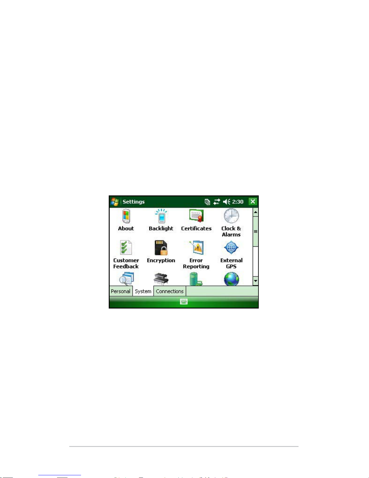
1. Tap S
tart > Seings. The Seings window appears.
2. Tap the System tab.
3. Choose System Cong. The System Conguration window
appears, listing the information you need for the service
center.
N
o
te: The numbers in the above screen may not be the numbers
on your Field PC.
Page 77

A
Product
Specifications and
Warnings
78 Product Specifications
79 B
attery Warnings
80 E
quipment Warnings
Page 78

78 Field PC Owner’s Manual
Product Specifications
Operating System Microso® Windows Mobile® 6
Processor Intel
®
XScale® PXA270, 624 MHz
Memory 128 MB RAM
Primary Storage 512 MB, 1G, 2G
Display Color 3.8” QVGA active matrix color
TFT transective LCD with LED
backlight; 320 x 240 pixels
Display Mono 4.1” QVGA with LED backlight; 320
x 240 pixels
Touchscreen Sealed, resistive, pressure sensitive,
enable/disable
Expansion and I/O
slots
Micro SD; PCMCIA 3.3/5 volts of
Type I or Type II
Keyboard All printable ASCII characters, 12
function keys
Operating
Temperature
–4° to 131° F (–20° to 55° C)
Storage Temperature –31° to 140° F (–35° to 60° C)
Baery Charging
Temperature
32° to 104° F (0° to 40° C)
Water, Sand and Dust
proof rating
IP67 sealed against accidental
immersion (1 m for 30 minutes)
Baery Pack Rechargeable nickel metal hydride
(NiMH)
Communications
Module
Serial port 9-pin D-sub connector,
USB Host (Full A), USB Client (Mini
B), power input 12 volts DC
COM 1 Port 9-pin D-sub connector; full modem
control signals, 5 V @ 200 mA
available on DTR pin 4; controlled
by DTR signal; conformal coated
Page 79

Power Input 12 volts DC; Range 10-20 VDC;
reverse polarity protection; over
voltage protection; auto shut o
Wireless
Communications
Optional integrated Bluetooth and
802.11 b/g WLAN (Wi-Fi)
Internal Clock Integrated real time clock with
baery backup
Enunciators On system tray
Battery Warnings
Follow these additional safety guidelines:
Use only baery packs approved for use with this device.
Do not store or leave your device or baery pack near a heat
source such as a radiator, replace, stove, electric heater, or
other heat-generating appliance, or otherwise expose it to
temperatures in excess of 140° F (60° C).
Do not try to open the baery pack.
Do not carry a baery pack in your pocket, purse, or other
container where metal objects (such as car keys or paper clips)
could short-circuit the baery pack terminals.
Keep the baery pack contacts clean. If they get dirty, wipe
them o with a so cloth.
Dispose of the baery pack properly. See the section called
D
i
sposing of your Field PC and baery packs in this manual
for instructions.
Do not install the baery pack backwards so that the polarity is
reversed.
Do not connect the positive terminal and the negative terminal of
the baery pack to each other with any metal object (such as wire).
Do not solder directly onto the baery pack.
Do not place the baery pack in direct sunshine.
A Product Specifications and Warnings 79
Page 80

80 Field PC Owner’s Manual
In the rare event that the baery pack leaks and uid gets
into the eye, do not rub the eye. Rinse well with water and
immediately seek medical care.
Risk of explosion if incorrect baery type is used.
Equipment Warnings
WARNING: To reduce the risk of personal injury, electrical
shock, re or damage to the equipment:
Plug the wall charger into an electrical outlet that is easily
accessible at all times.
Disconnect power from the equipment by unplugging the
wall charger from the electrical outlet or unplugging the
synchronization cable from the host computer.
Do not place anything on the wall charger cord or any of the
other cables. Arrange them so that no one may accidentally
step on or trip over them.
Do not pull on a cord or cable. When unplugging the wall
charger from the electrical outlet, pull on the plug, not the cord.
Use only wall chargers intended for the Field PC.
Using any
other external power source can damage your product and
void your warranty.
Us
ing the Field PC in extreme temperatures
The Field PC operates in ranges from –4° F to 131° F (–20° C to
55° C). To help your device function properly, store the device
indoors when possible.
Ot
her tips:
If the Field PC is exposed to temperatures below 14° F (–10° C),
the device may slow down or the display backlight may
become dim to reduce the load on the baery power.
Extremely low or high temperatures may prevent the baery
pack from charging. Charge the baery pack in temperatures
between 32° F and 104° F (0° C and 40° C). For best results,
c
h
arge the baery pack at room temperature (68° F or 20° C)
!
Page 81

B
Certifications
and Regulatory
Information
82 Regulatory Information
83 Limited P
roduct Warranty
Page 82

82 Field PC Owner’s Manual
Regulatory Information
FCC
This device complies with Part 15 of the FCC Rules. Operation
of this equipment is subject to the following two conditions:
1. The device may not cause harmful interference.
2
. This device must accept any interference received,
i
ncluding interference that may cause undesired operation.
Note: This equipment has been tested and found to comply with the
limits for a Class A digital device, pursuant to part 15 of the FCC
Rules. These limits are designed to provide reasonable protection
against harmful interference when the equipment is operated in
a
commercial environment. This equipment generates, uses, and
can radiate radio frequency energy and, if not installed and used
in accordance with the instruction manual, may cause harmful
interference to radio communications. Operation of this equipment in
a residential area is likely to cause harmful interference in which case
the user will be required to correct the interference at his own expense.
Note: This equipment has been tested and found to comply with the
limits for a Class B digital device, pursuant to part 15 of the FCC
Rules. These limits are designed to provide reasonable protection
against harmful interference in a residential installation. This
equipment generates, uses and can radiate radio frequency energy
and, if not installed and used in accordance with the instructions,
may cause harmful interference to radio communications. However,
there is no guarantee that interference will not occur in a particular
installation. If this equipment does cause harmful interference to
radio or television reception, which can be determined by turning
the equipment o and on, the user is encouraged to try to correct the
interference by one or more of the following measures:
Reorient or relocate the receiving antenna.
Increase the separation between the equipment and receiver.
Connect the equipment into an outlet on a circuit dierent
from that to which the receiver is connected.
Consult the dealer or an experienced radio/TV technician
for help.
Page 83

CAUTION: Changes or modications to the Field PC that are
not expressly approved by the manufacturer could void the
user’s authority to operate the equipment.
CAUTION: Only approved accessories may be used with this
equipment. In general, all cables must be high quality, shielded,
correctly terminated, and normally restricted to two meters in
length. Wall chargers approved for this product employ special
provisions to avoid radio interference and should not be altered
or substituted.
This device must not be co-located or operating in conjunction
with any other antenna or transmier.
This device operates in compliance with the FCC radiation
exposure limits for an uncontrolled environment. Users must
follow instructions provided in the user documentation to
satisfy compliance with FCC RF exposure requirements.
This device has been tested and meets the FCC RF exposure
guidelines when used with the body worn accessories supplied
with this product. Use of other accessories for body worn use
may expose the user to RF radiation that exceeds the FCC
guidelines.
I
n
dustry Canada
This Class B digital apparatus complies with Canadian
ICES-003.
Operation is subject to the following two conditions: (1) this
device may not cause interference, and (2) this device must
accept any interference, including interference that may cause
undesired operation of the device.
CE m
arking
Products bearing the CE marking comply with the
2004/108/EC (EMC Directive), 1999/5/EC (R&TTE
Directive), 2006/95/EC (Low Voltage Directive) issued by the
Commission of the European Community.
!
!
B Certifications and Regulatory Information 83
Page 84

84 Field PC Owner’s Manual
CE compliance of this device is valid only if powered with/by
a CE-marked wall charger provided by the manufacturer.
Compliance with these directives implies conformity to the
following European Norms (in parentheses are the equivalent
international standards and regulations):
EN 55022 (CISPR 22)—Electromagnetic Interference
EN 55024 (IEC 61000-4-2, 3, 4, 5, 6, 8, 11)—
Electromagnetic Immunity
EN 61000-3-2 (IEC 61000-3-2)—Power Line Harmonics
EN 61000-3-3 (IEC 61000-3-3)—Power Line Flicker
EN 60950 (IEC 60950)—Product Safety
ETS 300 328-2—Technical Requirements for 2.4 GHz
Radio Equipment
EN 301 489-1, -17—General EMC Requirements for
Radio Equipment
E
u
ropean Union
The telecommunication functions of this device may be used
in the following EU and EFTA countries: Austria, Belgium,
Bulgaria, Cyprus, Czech Republic, Denmark, Estonia,
Finland, France, Germany, Greece, Hungary, Iceland, Ireland,
Italy, Latvia, Liechtenstein, Lithuania, Luxembourg, Malta,
Netherlands, Norway, Poland, Portugal, Slovak Republic,
Romania, Slovenia, Spain, Sweden, Switzerland, and United
Kingdom.
Restrictions apply to the operation of the 802.11b/g radio in this
device. Use of channel 14 is outside of the band of frequencies
permied in the European Union and should not be used.
France
Restrictions apply to the operation of the Bluetooth radio in
this device. This equipment may be used indoors. Due to the
potential that this radio may transmit in excess of 10mW in the
band 2454 to 2483.5 MHz, outdoor operation is restricted. The
latest requirements may be found at: hp://www.art-telecom.fr
Page 85

Limited Product Warranty
Juniper Systems, Inc. (“JS”) warrants that the Field PC/Field
PCs shall be free from defects in materials and workmanship,
under normal intended use, for a period of 12 months from the
date of shipment. The Field PC can be warranted up to 5 years
(including the standard warranty period) through the purchase
of an extended warranty. JS warrants that the following items
shall be free from defects in materials and workmanship,
under normal intended use, for a period of ninety (90) days
from the date of shipment:
baery packs,
media containing the Field PC programs,
desktop computer programs,
user documentation, and
accessories.
Extended warranties apply only to the Field PC, not baery
packs, media containing the Field PC programs, desktop
computer programs, user documentation, and accessories.
Parts that are excessively worn are not covered under the
extended warranty plan. These parts may include, but are not
limited to, the keyboard elastomer and switch matrix, hand
straps, touchscreens, and connector modules.
W
a
rranty Exclusions
This warranty shall not apply if:
(i) the product has been set up improperly or has been
i
mproperly installed or calibrated,
(i
i) the product is operated in a manner that is not in
accordance with the user documentation,
(iii) the product is used for a purpose other than for which it
w
as designed,
B Certifications and Regulatory Information 85
Page 86

86 Field PC Owner’s Manual
(iv) the product has been used in environmental conditions
outside of those specied for the product,
(v) the product has been subject to any modication,
a
lteration, or change by or on behalf of customer (except
and unless modied, changed or altered by JS or under
direct supervision of JS),
(vi) the defect or malfunction results from misuse or accident,
(vii)
the serial number on the product has been tampered with
or removed, or
(viii)
the product has been opened or tampered with in any way.
This warranty is exclusive and JS will not assume and hereby
expressly disclaims any further warranties, whether express
or implied, including, without limitation, any warranty as
to merchantability, tness for a particular purpose, non-
infringement or any warranties arising from the course of
performance, dealing, or usage of trade. JS specically makes
no warranties as to the suitability of its products for any
particular application. JS makes no warranties that
its products will meet your requirements or will work in
combination with any hardware or applications soware
products provided by third parties,
the operation of its products will be uninterrupted or error
free, or
all defects in the product will be corrected.
JS shall not be responsible for soware, rmware, information,
or memory data contained in, stored on, or integrated with any
products returned to JS for repair, whether under warranty or not.
Remedy
In the event a defect in materials or workmanship is discovered
and reported to JS within the specied warranty period, JS will,
at its option, repair the defect or replace the defective part or
product. Replacement products may be new or reconditioned. JS
Page 87

warrants any replaced or repaired product for a period of ninety
(90) days from the date of return shipment, or through the end of
the original warranty period, whichever is longer.
Li
mitation of Liability
To the fullest extent allowed by law, the obligation of JS shall
be limited to the repair or replacement of the product. JS shall
in no event be liable for special, incidental, or consequential,
indirect, special or punitive damages of any kind, or for loss of
revenue or prots, loss of business, loss of information or data,
or other nancial loss arising out of or in connection with the
sale, installation, maintenance, use, performance, failure, or
interruption of any product. Any responsibility and/or liability
of JS shall, in connection with a warranted product, be limited
in the maximum amount to the original purchase price.
W
a
rranty Repairs
To obtain repair or service on the Field PC, contact your
authorized repair center within the applicable warranty
period to receive a Return Material Authorization (RMA)
number. Repairs returned without proper authorization may
acquire an additional handling fee and/or delay in the repair.
The customer is responsible to prepay all shipping costs
when sending equipment to a repair center. JS will return the
repaired equipment by the same method it was received with
costs of shipping prepaid.
G
o
verning Law
This warranty is governed by the laws of Utah, and excludes
the United Nations Convention on Contracts for the
International Sale of Goods. The courts of Utah shall have
exclusive personal jurisdiction in case of any disputes arising
out of or in connection with this warranty.
B Certifications and Regulatory Information 87
Page 88

88 Field PC Owner’s Manual
Services and M
aterials Provided Under Warranty
Analysis of problem by service technician
Labor and materials required to x defective parts
Functional analysis performed aer repair
Repair turnaround within 10 working days of receipt unless
special circumstances exist
Shipping costs to return device to customer
Page 89

Index
Page 90

90 Field PC Owner’s Manual
Index
A
ActiveSync 20
Backing up Data 44
Creating a connection 20
Re-establishing Connection 48
Alkaline Baery Holder
Install 15
Applications Manager 24, 42
Viewing Memory Allocation 42
B
Backing Up Data 44
To Desktop Computer 44
Backlight 24, 38
Timer 39
Baery Pack. S
e
e also Alkaline Baery Holder
Baery Seings Screen 12
Capacity 14
Charging Temperature 15, 78
Disposing of 73
Install 7
Percentage and Capacity 13
Recharging 14
Warnings 79
Baery Seings Screen. See
B
aery Pack
Bluetooth
Advanced Audio Distribution (A2DP) 57
Audio/Video Control 57
Beaming. See
O
bject Push Prole (OPP)
Create a Partnership 51
Dial-Up Networking (DUN) 60
Dial-Up Networking prole
using a cell phone to connect to the Internet 60
Dongle 58
Page 91

Drivers and Proles 50
File Transfer Prole (FTP) 57
Human Interface Device (HID) 61
Incoming COM Port 56
Internet using Dial-up Connection 60
Make Discoverable 50
Object Push Prole (OPP) 61
Outgoing COM Port 54
Passkey 52
Print 59
Serial Port Prole (SPP) 57
Virtual COM Port 53
Wireless Manager 50
Bluetooth Proles
Proles 56
C
Care and Maintenance 68
Cleaning 70
Protecting Against Mechanical Shock 70
Protecting the touchscreen 70
Storage 68
Less Than Two Months 68
More Than Two Months 69
Taking Out 69
CE Marking 83
CF Card. See
P
C Card
Communicating with a Desktop Computer 20, 48. See also Ac-
t
iveSync and Windows Mobile Device Center
Communications Module 78
Connector Protectors 26
Contrast/Brightness 24, 39
Copying Data 46
Creating a Name 40
Index 91
Page 92

92 Field PC Owner’s Manual
D
Data Entry 35
Block Recognizer 36
Keyboard Utility 35
Leer Recognizer 35
Transcriber 36
Display
Product Specications 78
E
Equipment Warnings 80
Exploring Files 41
G
Geing Started Disc 20
K
Keyboard 24
Cleaning 71
Diagram 24
Shi Keys 25
Blue 24
Orange 24
M
Memory 78
Micro SD Card 30
Microso Website 43
N
New Baery Detected. See Baery Pack
O
On-device Help 43
Operating System 78
Page 93

P
PC Card 30
Power Buon 24, 26
Powering O 26
Reseing the Device 27
Restoring Factory State 28
Suspending 27
Product Specications 78
R
Regulatory Information 82
Repairing 76
Return Materials Authorization (RMA) 76
Return Materials Authorization. See
R
epairing
S
SD Card. See PC Card
So Keys 38
Le 24
Right 24
Soware Developers Kit 48
Start Menu 35
Windows Buon 24
Status Icons 37
Baery Capacity 37
Charge Indicator 37
Speaker 37
Touch Screen 37
Stylus 28
T
Task Manager 42
Close Unused Programs 42
Switching Between Running Programs 42
Index 93
Page 94

94 Field PC Owner’s Manual
Temperatures
Baery Charging 78
Charging Baery Pack. S
e
e also Baery Pack
Extreme 80
Operating 78
Storage 78
Today Screen 34
Touch Screen 24, 29
Calibrating 29
Cleaning 72
Disabling 29
Protecting 29, 70
U
USB/Power Dock 16
Charging 17
LED Indicators 16
Power Supply 17
USB Communication 18
V
Vehicle Power 18
Vehicle Mode 18
W
Wi-Fi 64
Connecting to Network 64
Managing Connections 66
Status Icons 64
Windows Mobile Device Center 21
Backing Up Data 45
Creating a Connection 21
Re-establish Connection 48
 Loading...