

Page 1

EX9251 Switch Hardware Guide
Published
2021-01-31
Page 2

Juniper Networks, Inc.
1133 Innovation Way
Sunnyvale, California 94089
USA
408-745-2000
www.juniper.net
Juniper Networks, the Juniper Networks logo, Juniper, and Junos are registered trademarks of Juniper Networks, Inc. in
the United States and other countries. All other trademarks, service marks, registered marks, or registered service marks
are the property of their respective owners.
Juniper Networks assumes no responsibility for any inaccuracies in this document. Juniper Networks reserves the right
to change, modify, transfer, or otherwise revise this publication without notice.
EX9251 Switch Hardware Guide
Copyright © 2021 Juniper Networks, Inc. All rights reserved.
The information in this document is current as of the date on the title page.
ii
YEAR 2000 NOTICE
Juniper Networks hardware and software products are Year 2000 compliant. Junos OS has no known time-related
limitations through the year 2038. However, the NTP application is known to have some difficulty in the year 2036.
END USER LICENSE AGREEMENT
The Juniper Networks product that is the subject of this technical documentation consists of (or is intended for use with)
Juniper Networks software. Use of such software is subject to the terms and conditions of the End User License Agreement
(“EULA”) posted at https://support.juniper.net/support/eula/. By downloading, installing or using such software, you
agree to the terms and conditions of that EULA.
Page 3

Table of Contents
1
About the Documentation | xi
Documentation and Release Notes | xi
Using the Examples in This Manual | xi
Merging a Full Example | xii
Merging a Snippet | xiii
Documentation Conventions | xiii
Documentation Feedback | xvi
Requesting Technical Support | xvi
Self-Help Online Tools and Resources | xvii
Creating a Service Request with JTAC | xvii
iii
Overview
EX9251 System Overview | 19
EX9251 Switch Hardware Overview | 19
Software | 20
Benefits of the EX9251 Switch | 20
EX9251 Switch Models | 20
Front Panel of an EX9251 Switch | 20
Rear Panel of an EX9251 Switch | 22
Routing Engine | 22
Power Supplies | 23
Cooling System | 23
Component Redundancy | 23
EX9251 Switch Models | 24
EX9251 Switch Hardware and CLI Terminology Mapping | 24
EX9251 Chassis | 26
Chassis Physical Specifications of an EX9251 Switch | 26
Field-Replaceable Units in an EX9251 Switch | 27
Page 4

LEDs on the Front Panel of an EX9251 Switch | 27
2
EX9251 Cooling System | 33
Fan Trays | 33
Airflow Direction in the EX9251 Switch Chassis | 34
Cooling System in the Power Supplies | 35
Fan Tray Status LEDs | 35
EX9251 Power System | 36
Power Supplies in an EX9251 Switch | 36
AC Power Supply Description | 37
AC Power Supply LEDs and Other Components | 38
DC Power Supply Description | 40
DC Power Supply LEDs and Other Components | 40
AC Power Cord Specifications for an EX9251 Switch | 42
iv
Power Requirements for EX9251 Switch Components | 44
Power Requirements for EX9251 Switch Components | 44
Calculating System Thermal Output | 45
Power Supply Specifications for EX9251 Switches | 45
Site Planning, Preparation, and Specifications
Site Preparation Checklist for an EX9251 Switch | 48
EX9251 Site Guidelines and Requirements | 49
Environmental Requirements and Specifications for EX Series Switches | 49
General Site Guidelines | 54
Site Electrical Wiring Guidelines | 55
Clearance Requirements for Airflow and Hardware Maintenance for EX9251 Switches | 56
Rack and Cabinet Requirements for EX9251 Switches | 57
EX9251 Network Cable and Transceiver Planning | 60
Pluggable Transceivers Supported on EX9251 Switches | 60
SFP+ Direct Attach Copper Cables for EX Series Switches | 61
Cable Specifications | 62
List of DAC Cables Supported on EX Series Switches | 62
Page 5

Standards Supported by These Cables | 63
QSFP+ Direct Attach Copper Cables for EX Series Switches | 63
Cable Specifications | 64
DAC Cables Supported on EX3400, EX4300, EX4550, EX4600, EX9251, and EX9253
Switches | 64
Understanding EX Series Switches Fiber-Optic Cable Signal Loss, Attenuation, and
Dispersion | 64
Signal Loss in Multimode and Single-Mode Fiber-Optic Cable | 65
Attenuation and Dispersion in Fiber-Optic Cable | 65
Calculating the Fiber-Optic Cable Power Budget for EX Series Devices | 66
Calculating the Fiber-Optic Cable Power Margin for EX Series Devices | 66
EX9251 Management Cable Specifications and Pinouts | 68
Management Cable Specifications | 69
Specifications of Cables and Wires That Connect to Ports on the Front Panel in an EX9251
Switch | 69
v
Grounding Cable and Lug Specifications for EX9251 Switches | 70
Grounding Points Specifications for an EX9251 Switch | 70
Grounding Cable Specifications for an EX9251 Switch | 71
Grounding Lug Specifications for an EX9251 Switch | 71
USB Port Specifications for an EX Series Switch | 71
Console Port Connector Pinout Information for an EX9251 Switch | 72
RJ-45 to DB-9 Serial Port Adapter Pinout Information | 73
RJ-45 Management Port Connector Pinout Information | 73
Page 6

Initial Installation and Configuration
3
Unpacking and Mounting the EX9251 Switch | 76
Unpacking an EX9251 Switch | 76
Parts Inventory (Packing List) for an EX9251 Switch | 77
Register Products—Mandatory to Validate SLAs | 79
Installing and Connecting an EX9251 Switch | 79
Mounting an EX9251 Switch on a Rack or Cabinet | 80
Mounting an EX9251 Switch on a 19-in. Rack | 81
Installing an EX9251 Switch in an ETSI Rack | 84
Connecting the EX9251 to Power | 88
Connect Earth Ground to an EX Series Switch | 88
Parts and Tools Required for Connecting an EX Series Switch to Earth Ground | 89
Special Instructions to Follow Before Connecting Earth Ground to an EX Series Switch | 93
vi
Connecting Earth Ground to an EX Series Switch | 94
Connecting AC Power to an EX9251 Switch and Powering on the Switch | 95
Connecting DC Power to an EX9251 Switch and Powering on the Switch | 99
Connecting the EX9251 to External Devices | 103
Connect a Device to a Network for Out-of-Band Management | 103
Connect a Device to a Management Console Using an RJ-45 Connector | 104
Connecting the EX9251 Switch to External Clocking and Timing Devices | 105
Connecting 1-PPS and 10-MHz Timing Devices to the Switch | 106
Connecting a Time-of-Day Device to the Switch | 107
Connecting a BITS External Clocking Device to the Switch | 107
Connecting the EX9251 to the Network | 108
Install a Transceiver | 108
Connect a Fiber-Optic Cable | 111
Configuring Junos OS on the EX9251 | 112
EX9251 Switch Default Configuration | 112
Connecting and Configuring an EX9251 Switch (CLI Procedure) | 113
Page 7

Maintaining Components
4
5
Routine Maintenance Procedures for EX9251 Switches | 119
Routine Maintenance Procedures for EX9251 Switches | 119
Maintaining the Routing Engine in EX9251 Switches | 119
Maintaining the EX9251 Cooling System | 121
Removing a Fan Tray from an EX9251 Switch | 121
Installing a Fan Tray in an EX9251 Switch | 122
Maintaining Fan Trays in EX9251 Switches | 124
Maintaining the EX9251 Power System | 125
Powering Off an EX9251 Switch | 125
Removing an AC Power Supply from an EX9251 Switch | 126
Installing an AC Power Supply in an EX9251 Switch | 128
vii
Removing a DC Power Supply from an EX9251 Switch | 129
Installing a DC Power Supply in an EX9251 Switch | 131
Maintaining Power Supplies in EX9251 Switches | 133
Maintaining Transceivers | 134
Remove a Transceiver | 135
Install a Transceiver | 138
Remove a QSFP28 Transceiver | 140
Install a QSFP28 Transceiver | 142
Maintain Fiber-Optic Cables | 144
Connect a Fiber-Optic Cable | 144
Disconnect a Fiber-Optic Cable | 145
How to Handle Fiber-Optic Cables | 146
Troubleshooting Hardware
Troubleshooting EX9251 Components | 149
Troubleshooting the Cooling System in an EX9251 Switch | 149
Troubleshooting Power Supplies in an EX9251 Switch | 150
Troubleshoot Temperature Alarms in EX Series Switches | 151
Page 8

Contacting Customer Support and Returning the Chassis or Components
6
7
Returning an EX9251 Chassis or Components | 158
Returning an EX9251 Switch or Component for Repair or Replacement | 158
Locating the Serial Number on an EX9251 Switch or Component | 159
Locating the Serial Number ID Label on an EX9251 Switch Chassis | 159
Locating Serial Number ID Labels on FRU Components | 159
Contact Customer Support to Obtain Return Material Authorization | 161
Packing an EX9251 Switch or Component | 162
Packing an EX9251 Switch | 162
Packing EX9251 Switch Components for Shipping | 163
Safety and Compliance Information
General Safety Guidelines and Warnings | 167
viii
Definitions of Safety Warning Levels | 168
Qualified Personnel Warning | 171
Warning Statement for Norway and Sweden | 172
Fire Safety Requirements | 172
Fire Suppression | 172
Fire Suppression Equipment | 172
Installation Instructions Warning | 174
Chassis and Component Lifting Guidelines | 174
Restricted Access Warning | 176
Ramp Warning | 178
Rack-Mounting and Cabinet-Mounting Warnings | 179
Grounded Equipment Warning | 185
Radiation from Open Port Apertures Warning | 186
Laser and LED Safety Guidelines and Warnings | 187
General Laser Safety Guidelines | 187
Class 1 Laser Product Warning | 188
Page 9

Class 1 LED Product Warning | 189
Laser Beam Warning | 190
Maintenance and Operational Safety Guidelines and Warnings | 190
Battery Handling Warning | 192
Jewelry Removal Warning | 193
Lightning Activity Warning | 195
Operating Temperature Warning | 196
Product Disposal Warning | 198
General Electrical Safety Guidelines and Warnings | 199
Action to Take After an Electrical Accident | 200
Prevention of Electrostatic Discharge Damage | 201
AC Power Electrical Safety Guidelines | 202
ix
AC Power Disconnection Warning | 204
DC Power Electrical Safety Guidelines | 205
DC Power Disconnection Warning | 206
DC Power Grounding Requirements and Warning | 208
DC Power Wiring Sequence Warning | 210
DC Power Wiring Terminations Warning | 213
Multiple Power Supplies Disconnection Warning | 216
TN Power Warning | 217
Agency Approvals for EX9251 Switches | 217
Compliance Statements for EMC Requirements for EX Series Switches | 219
Canada | 219
Taiwan | 220
European Community | 220
Israel | 220
Japan | 221
Korea | 221
Page 10

United States | 221
FCC Part 15 Statement | 222
Nonregulatory Environmental Standards | 222
Compliance Statements for Acoustic Noise for EX Series Switches | 223
Statements of Volatility for Juniper Network Devices | 224
x
Page 11

About the Documentation
IN THIS SECTION
Documentation and Release Notes | xi
Using the Examples in This Manual | xi
Documentation Conventions | xiii
Documentation Feedback | xvi
Requesting Technical Support | xvi
Use this guide to install hardware and perform initial software configuration, routine maintenance, and
troubleshooting for the EX9251 switch. After completing the installation and basic configuration procedures
covered in this guide, refer to the Junos OS documentation for information about further software
configuration.
xi
Documentation and Release Notes
To obtain the most current version of all Juniper Networks®technical documentation, see the product
documentation page on the Juniper Networks website at https://www.juniper.net/documentation/.
If the information in the latest release notes differs from the information in the documentation, follow the
product Release Notes.
Juniper Networks Books publishes books by Juniper Networks engineers and subject matter experts.
These books go beyond the technical documentation to explore the nuances of network architecture,
deployment, and administration. The current list can be viewed at https://www.juniper.net/books.
Using the Examples in This Manual
If you want to use the examples in this manual, you can use the load merge or the load merge relative
command. These commands cause the software to merge the incoming configuration into the current
candidate configuration. The example does not become active until you commit the candidate configuration.
Page 12

If the example configuration contains the top level of the hierarchy (or multiple hierarchies), the example
is a full example. In this case, use the load merge command.
If the example configuration does not start at the top level of the hierarchy, the example is a snippet. In
this case, use the load merge relative command. These procedures are described in the following sections.
Merging a Full Example
To merge a full example, follow these steps:
1. From the HTML or PDF version of the manual, copy a configuration example into a text file, save the
file with a name, and copy the file to a directory on your routing platform.
For example, copy the following configuration to a file and name the file ex-script.conf. Copy the
ex-script.conf file to the /var/tmp directory on your routing platform.
system {
scripts {
commit {
file ex-script.xsl;
}
}
}
interfaces {
fxp0 {
disable;
unit 0 {
family inet {
address 10.0.0.1/24;
}
}
}
}
xii
2. Merge the contents of the file into your routing platform configuration by issuing the load merge
configuration mode command:
[edit]
user@host# load merge /var/tmp/ex-script.conf
load complete
Page 13

Merging a Snippet
To merge a snippet, follow these steps:
1. From the HTML or PDF version of the manual, copy a configuration snippet into a text file, save the
file with a name, and copy the file to a directory on your routing platform.
For example, copy the following snippet to a file and name the file ex-script-snippet.conf. Copy the
ex-script-snippet.conf file to the /var/tmp directory on your routing platform.
commit {
file ex-script-snippet.xsl; }
2. Move to the hierarchy level that is relevant for this snippet by issuing the following configuration mode
command:
[edit]
user@host# edit system scripts
[edit system scripts]
xiii
3. Merge the contents of the file into your routing platform configuration by issuing the load merge
relative configuration mode command:
[edit system scripts]
user@host# load merge relative /var/tmp/ex-script-snippet.conf
load complete
For more information about the load command, see CLI Explorer.
Documentation Conventions
Table 1 on page xiv defines notice icons used in this guide.
Page 14
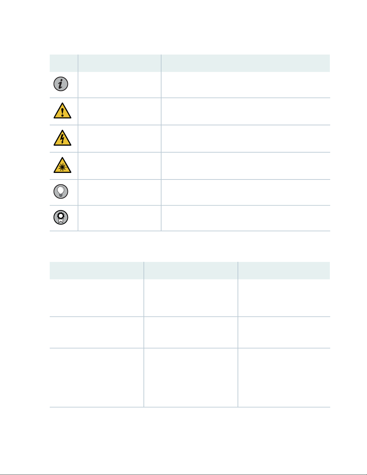
Table 1: Notice Icons
xiv
DescriptionMeaningIcon
Indicates important features or instructions.Informational note
Caution
Indicates a situation that might result in loss of data or hardware
damage.
Alerts you to the risk of personal injury or death.Warning
Alerts you to the risk of personal injury from a laser.Laser warning
Indicates helpful information.Tip
Alerts you to a recommended use or implementation.Best practice
Table 2 on page xiv defines the text and syntax conventions used in this guide.
Table 2: Text and Syntax Conventions
ExamplesDescriptionConvention
Fixed-width text like this
Italic text like this
Represents text that you type.Bold text like this
Represents output that appears on
the terminal screen.
Introduces or emphasizes important
•
new terms.
Identifies guide names.
•
Identifies RFC and Internet draft
•
titles.
To enter configuration mode, type
the configure command:
user@host> configure
user@host> show chassis alarms
No alarms currently active
A policy term is a named structure
•
that defines match conditions and
actions.
Junos OS CLI User Guide
•
RFC 1997, BGP Communities
•
Attribute
Page 15

Table 2: Text and Syntax Conventions (continued)
xv
ExamplesDescriptionConvention
Italic text like this
Text like this
< > (angle brackets)
| (pipe symbol)
Represents variables (options for
which you substitute a value) in
commands or configuration
statements.
Represents names of configuration
statements, commands, files, and
directories; configuration hierarchy
levels; or labels on routing platform
components.
variables.
Indicates a choice between the
mutually exclusive keywords or
variables on either side of the symbol.
The set of choices is often enclosed
in parentheses for clarity.
Configure the machine’s domain
name:
[edit]
root@# set system domain-name
domain-name
To configure a stub area, include
•
the stub statement at the [edit
protocols ospf area area-id]
hierarchy level.
The console port is labeled
•
CONSOLE.
stub <default-metric metric>;Encloses optional keywords or
broadcast | multicast
(string1 | string2 | string3)
# (pound sign)
[ ] (square brackets)
Indention and braces ( { } )
; (semicolon)
GUI Conventions
Indicates a comment specified on the
same line as the configuration
statement to which it applies.
Encloses a variable for which you can
substitute one or more values.
Identifies a level in the configuration
hierarchy.
Identifies a leaf statement at a
configuration hierarchy level.
rsvp { # Required for dynamic MPLS
only
community name members [
community-ids ]
[edit]
routing-options {
static {
route default {
nexthop address;
retain;
}
}
}
Page 16

Table 2: Text and Syntax Conventions (continued)
xvi
ExamplesDescriptionConvention
Bold text like this
> (bold right angle bracket)
Represents graphical user interface
(GUI) items you click or select.
Separates levels in a hierarchy of
menu selections.
In the Logical Interfaces box, select
•
All Interfaces.
To cancel the configuration, click
•
Cancel.
In the configuration editor hierarchy,
select Protocols>Ospf.
Documentation Feedback
We encourage you to provide feedback so that we can improve our documentation. You can use either
of the following methods:
Online feedback system—Click TechLibrary Feedback, on the lower right of any page on the Juniper
•
Networks TechLibrary site, and do one of the following:
Click the thumbs-up icon if the information on the page was helpful to you.
•
Click the thumbs-down icon if the information on the page was not helpful to you or if you have
•
suggestions for improvement, and use the pop-up form to provide feedback.
E-mail—Send your comments to techpubs-comments@juniper.net. Include the document or topic name,
•
URL or page number, and software version (if applicable).
Requesting Technical Support
Technical product support is available through the Juniper Networks Technical Assistance Center (JTAC).
If you are a customer with an active Juniper Care or Partner Support Services support contract, or are
Page 17

covered under warranty, and need post-sales technical support, you can access our tools and resources
online or open a case with JTAC.
JTAC policies—For a complete understanding of our JTAC procedures and policies, review the JTAC User
•
Guide located at https://www.juniper.net/us/en/local/pdf/resource-guides/7100059-en.pdf.
Product warranties—For product warranty information, visit https://www.juniper.net/support/warranty/.
•
JTAC hours of operation—The JTAC centers have resources available 24 hours a day, 7 days a week,
•
365 days a year.
Self-Help Online Tools and Resources
For quick and easy problem resolution, Juniper Networks has designed an online self-service portal called
the Customer Support Center (CSC) that provides you with the following features:
Find CSC offerings: https://www.juniper.net/customers/support/
•
Search for known bugs: https://prsearch.juniper.net/
•
xvii
Find product documentation: https://www.juniper.net/documentation/
•
Find solutions and answer questions using our Knowledge Base: https://kb.juniper.net/
•
Download the latest versions of software and review release notes:
•
https://www.juniper.net/customers/csc/software/
Search technical bulletins for relevant hardware and software notifications:
•
https://kb.juniper.net/InfoCenter/
Join and participate in the Juniper Networks Community Forum:
•
https://www.juniper.net/company/communities/
Create a service request online: https://myjuniper.juniper.net
•
To verify service entitlement by product serial number, use our Serial Number Entitlement (SNE) Tool:
https://entitlementsearch.juniper.net/entitlementsearch/
Creating a Service Request with JTAC
You can create a service request with JTAC on the Web or by telephone.
Visit https://myjuniper.juniper.net.
•
Call 1-888-314-JTAC (1-888-314-5822 toll-free in the USA, Canada, and Mexico).
•
For international or direct-dial options in countries without toll-free numbers, see
https://support.juniper.net/support/requesting-support/.
Page 18

1
CHAPTER
Overview
EX9251 System Overview | 19
EX9251 Chassis | 26
EX9251 Cooling System | 33
EX9251 Power System | 36
Page 19

EX9251 System Overview
IN THIS SECTION
EX9251 Switch Hardware Overview | 19
EX9251 Switch Models | 24
EX9251 Switch Hardware and CLI Terminology Mapping | 24
EX9251 Switch Hardware Overview
19
IN THIS SECTION
Software | 20
Benefits of the EX9251 Switch | 20
EX9251 Switch Models | 20
Front Panel of an EX9251 Switch | 20
Rear Panel of an EX9251 Switch | 22
Routing Engine | 22
Power Supplies | 23
Cooling System | 23
Component Redundancy | 23
Juniper Networks EX9251 Ethernet Switch is an Ethernet-optimized switch that provides carrier-class
Ethernet switching. It is a fixed configuration switch with a built-in Routing Engine. It has a throughput of
up to 400 gigabits per second (Gbps).
The switch has eight 10-Gigabit Ethernet ports and four rate-selectable ports that you can configure as
100-Gigabit Ethernet ports or 40-Gigabit Ethernet ports; each rate-selectable port can be configured as
four 10-Gigabit Ethernet ports by using a breakout cable. The 10-Gigabit Ethernet ports support SFP+
transceivers and rate-selectable ports support QSFP28 and QSFP+ transceivers. The switch supports two
power supplies and three fan trays.
Page 20

Software
Juniper Networks EX Series Ethernet Switches run Junos OS, which provides Layer 2 and Layer 3 switching,
routing, and security services. The same Junos OS code base that runs on EX Series switches also runs on
all Juniper Networks M Series, MX Series, and T Series routers, and SRX Series Services Gateways.
Benefits of the EX9251 Switch
Simplified network architecture—EX9251 switches deliver a simple, secure, virtualized network environment
that increases business agility. They are ideal for simplifying campus, data center, and combined campus
and data center network environments by collapsing network layers.
Support for Junos Fusion Enterprise—EX9251 switches support Junos Fusion Enterprise technology that
enables a large number of devices deployed throughout a building to be managed as a single, logical device,
thus reducing network complexity, simplifying network management, and lowering operational costs.
EX9251 Switch Models
20
EX9251 switch is available in two models—with AC power supply and with DC power supply. See “EX9251
Switch Models” on page 24.
Front Panel of an EX9251 Switch
Figure 1 on page 21 shows the front panel of an EX9251 switch.
Page 21
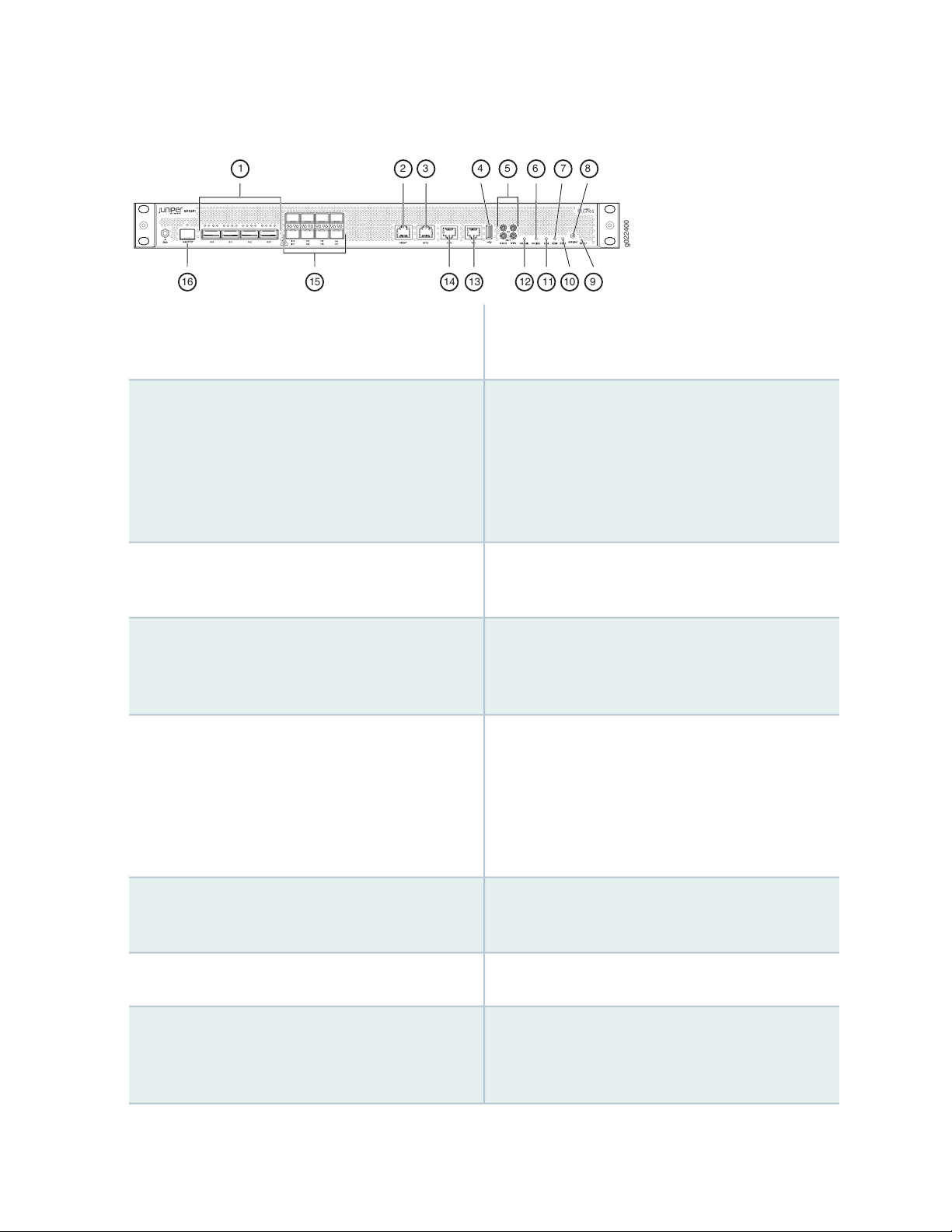
Figure 1: Front Panel of an EX9251 Switch
g022400
15
8
1016
732 4 6
9
1 5
1314 1112
100G, 40G, and 10G speeds and support transceivers
and direct attach copper (DAC) cables.
21
9—1— Reset button—button to reset the switch.Rate-selectable ports—These ports can operate in
Management Ethernet port—This port connects the
switch to a management device (or any other device
that plugs into an Ethernet connection) for
out-of-band management through an Ethernet
connection. The port uses an autosensing RJ-45
connector to support 10-Mbps, 100-Mbps, or
1000-Mbps connections.
supply (BITS) external clocking port, that connects
the switch to external clocking devices.
interface that you can use to install Junos OS
manually. Junos OS supports USB version 1.0 and
later.
1PPS and 10 MHz GPS input and output timing
ports—1-pulse-per-second (PPS) connectors and
10-MHz timing connectors respectively (one input
and one output), that connects the switch to external
clock signal sources. The clocking ports provide the
synchronized output clocks from any one of the
reference clock inputs based on the clock’s priority.
10—2— SSD0 LED—indicates the status of the solid-state
drive labeled SSD0.
11—3— Alarm LED—indicates alarms.BITS ports with LEDs—Building-integrated timing
12—4— OK/Fail LED—indicates the status of the switch.USB port—USB port, that provides a removable media
13—5— Time of day (ToD) port with LED—ToD port, that
connects the switch to external timing signal sources.
Online LED—indicates the status of the switch and
the operating system.
SSD1 LED—indicates the status of the solid-state
drive labeled SSD1.
Offline button—button to turn the switch online or
offline or to power on or power off the switch.
14—6— Console port—Console port, that connects the switch
to a system console through a serial cable with an
RJ-45 connector.
15—7— 10-Gigabit Ethernet SFP+ ports—support SFP+
transceivers and direct attach copper (DAC) cables.
16—8— PTP grandmaster clock (GM/PTP) port—PTP
grandmaster clock port, that connects the switch to
a timing device. Support for this port is not available
in this release.
Page 22
Rear Panel of an EX9251 Switch
g022401
3
1
4
2
5
g022042
1 2
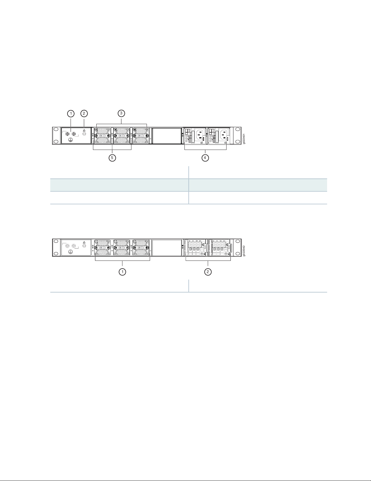
Figure 2 on page 22 shows the rear panel of an EX9251 switch with AC power supply. Figure 3 on page 22
shows the rear panel of an EX9251 switch with DC power supply.
Figure 2: Rear Panel of an EX9251 Switch with AC Power Supply
4—1— Fan tray LEDsProtective earthing terminal
5—2— AC power supply unitsElectrostatic discharge (ESD) point
3—Fan trays
22
Figure 3: Rear Panel of an EX9251 Switch with DC Power Supply
2—1— DC power supply unitsFan trays
Routing Engine
EX9251 switches have a single built-in Routing Engine. It provides switching protocol processes and
software processes that control the switch’s interface, the chassis components, system management, and
user access to the switch. These switching processes run on top of a kernel that interacts with the Packet
Forwarding Engine. The Routing Engine is built-in on the baseboard and cannot be replaced.
It supports the following functionalities to manage the operation of the switch:
System control functions such as environmental monitoring
•
Routing Layer 2 and Layer 3 protocols
•
Communication to components such as power supplies and fan trays
•
Page 23

Transparent clocking
•
Alarm and logging functions
•
It consists of the following internal components:
High-performance 1.6-GHz Intel 8 Core X86 CPU
•
32-GB DDR4 RAM
•
2x100-GB SATA SSD
•
Power Supplies
EX9251 switches support AC power supply and DC power supply. See “Power Supplies in an EX9251
Switch” on page 36.
CAUTION: Do not mix AC and DC power supplies in the same chassis.
23
Cooling System
The cooling system in an EX9251 switch consists of three fan trays. The fan trays are installed on the rear
panel of the chassis. Each fan tray contains one counter rotating fan. See “EX9251 Cooling System” on
page 33.
Component Redundancy
A fully configured EX9251 switch is designed such that no single point of failure can cause the entire
system to fail. The following major hardware components are redundant:
Power supplies—The switch supports two power supplies. If one power supply fails in a fully configured
•
switch, the other power supply can provide full power to the switch.
Cooling system—The switch supports three fan trays. If one fan fails or the temperature of the chassis
•
rises above the temperature threshold in a fully configured switch, the speed of the remaining fans is
automatically adjusted to keep the temperature within the acceptable range.
CAUTION: In a fully configured switch, all the three fan trays and the two power
supplies must be operational. In the event of any failure, the failed component must
be replaced immediately.
Page 24

EX9251 Switch Models
EX9251 is available in two models—with AC power supply and with DC power supply. Table 3 on page 24
lists the models and the components included in each model.
Table 3: EX9251 Switch Models
First Junos OS
ReleaseConfiguration ComponentsSwitch Models
24
EX9251-8X4C
EX9251-8X4C-DC
Chassis
•
Three fan trays
•
Two AC power supplies
•
Chassis
•
Three fan trays
•
Two DC power supplies
•
18.1R1
18.1R1
EX9251 Switch Hardware and CLI Terminology Mapping
This topic describes the hardware terms used in EX9251 switch documentation and the corresponding
terms used in the Junos OS CLI. See Table 4 on page 24.
Table 4: CLI Equivalents of Terms Used in Documentation for EX9251 Switches
Hardware
Item (CLI)
Item in
DocumentationValue (CLI)Description (CLI)
Additional
Information
Engine
Switch chassis–EX9251Chassis
Routing Engine0EX9251-RERouting
Routing Engine0EX9251CB
“Chassis Physical
Specifications of an
EX9251 Switch” on
page 26
“EX9251 Switch
Hardware Overview” on
page 19
“EX9251 Switch
Hardware Overview” on
page 19
––0FPCFPC
Page 25

Table 4: CLI Equivalents of Terms Used in Documentation for EX9251 Switches (continued)
25
Hardware
Item (CLI)
PIC (n)
Xcvr (n)
PEM (n)
Abbreviated name of
the Physical
Interface Card (PIC).
One of the following:
4XQSFP28 PIC
•
8XSFPP PIC
•
Abbreviated name of
the transceiver.
One of the following:
AC AFO 650W
•
PSU
JPSU-650W-DC-AFO
•
0-1. The value
corresponds to the PIC
slot number.
the number of the port in
which the transceiver is
installed.
n is a value in the range
0-1. The value
corresponds to the power
supply slot number.
Item in
DocumentationValue (CLI)Description (CLI)
Optical transceiversn is a value equivalent to
AC or DC power
supply
Additional
Information
––n is a value in the range
Hardware Compatibility
Tool page for EX9251
“Power Supplies in an
EX9251 Switch” on
page 36
Fan tray (n)
Fan Tray, Front to
Back Airflow - AFO
Fan trayn is a value in the range
0-2. The value
corresponds to the fan
tray slot number.
“EX9251 Cooling
System” on page 33
Table 5 on page 25 lists the spare parts and blank panels available for the switch. They must be ordered
separately.
Table 5: Spare Parts and Blank Panels
DescriptionModel Number
EX9251 chassis, spareEX9251-CHAS
EX9251 power supply slot blank panelJNP-PWR-BLNK-1
Page 26

EX9251 Chassis
IN THIS SECTION
Chassis Physical Specifications of an EX9251 Switch | 26
Field-Replaceable Units in an EX9251 Switch | 27
LEDs on the Front Panel of an EX9251 Switch | 27
Chassis Physical Specifications of an EX9251 Switch
The EX9251 switch chassis is a rigid sheet-metal structure that houses all components of the switch.
EX9251 is available in two variants—with AC power supply and with DC power supply. Table 6 on page 26
summarizes the physical specifications of the EX9251 switch chassis.
26
Table 6: Physical Specifications of the EX9251 Switch Chassis
19 in. (48.26 cm)22.7 lb (10.3 kg)Chassis
18.5 in. (47 cm)
•
20.43 in.
•
(51.89 cm) with
fan tray and
power supply
handles
You can mount an EX9251 switch on four posts of a 19-in. rack or an ETSI rack.
HeightDepthWidthWeightDescription
1.72 in. (4.37 cm)
1.64 in. (4.17 cm)5.78 in. (14.68 cm)1.89 in. (4.8 cm)0.29 lb (0.13 kg)Fan tray
1.58 in. (4.01 cm)14.5 in. (36.83 cm)2.23 in. (5.66 cm)2.2 lb (1 kg)AC power supply
1.67 in. (4.24 cm)14.53 in. (36.91 cm)2.23 in. (5.66 cm)2.2 lb (1 kg)DC power supply
Page 27

Field-Replaceable Units in an EX9251 Switch
Field-replaceable units (FRUs) are components that you can replace at your site. The FRUs in EX9251
switches are hot-removable and hot-insertable. You can remove and replace them without powering off
the switch. The FRUs in EX9251 switches are:
Power supplies
•
Fan trays
•
Transceivers
•
NOTE: If you have a Juniper J-Care service contract, register any addition, change, or upgrade
of hardware components at
https://www.juniper.net/customers/support/tools/updateinstallbase/ . Failure to do so can
result in significant delays if you need replacement parts. This note does not apply if you replace
existing components with the same type of component.
27
To install an AC power supply in an EX9251 switch, follow instructions in “Installing an AC Power Supply
in an EX9251 Switch” on page 128. To remove an AC power supply from an EX9251 switch, follow
instructions in “Removing an AC Power Supply from an EX9251 Switch” on page 126.
To install a DC power supply in an EX9251 switch, follow instructions in “Installing a DC Power Supply in
an EX9251 Switch” on page 131. To remove a DC power supply from an EX9251 switch, follow instructions
in “Removing a DC Power Supply from an EX9251 Switch” on page 129.
To install a fan tray in an EX9251 switch, follow instructions in “Installing a Fan Tray in an EX9251 Switch”
on page 122. To remove a fan tray from an EX9251 switch, follow instructions in “Removing a Fan Tray
from an EX9251 Switch” on page 121.
To install a transceiver in an EX9251 switch, follow instructions in “Install a Transceiver” on page 108 or
“Install a QSFP28 Transceiver” on page 142. To remove a transceiver from an EX9251 switch, follow
instructions in “Remove a Transceiver” on page 135 or “Remove a QSFP28 Transceiver” on page 140.
LEDs on the Front Panel of an EX9251 Switch
The four rate-selectable ports on the front panel of an EX9251 switch has four LEDs each, which indicate
the link status and activity on the port. Figure 4 on page 28 shows the LEDs on the rate-selectable ports.
Table 7 on page 28 describes the link activity LED on those ports.
Page 28
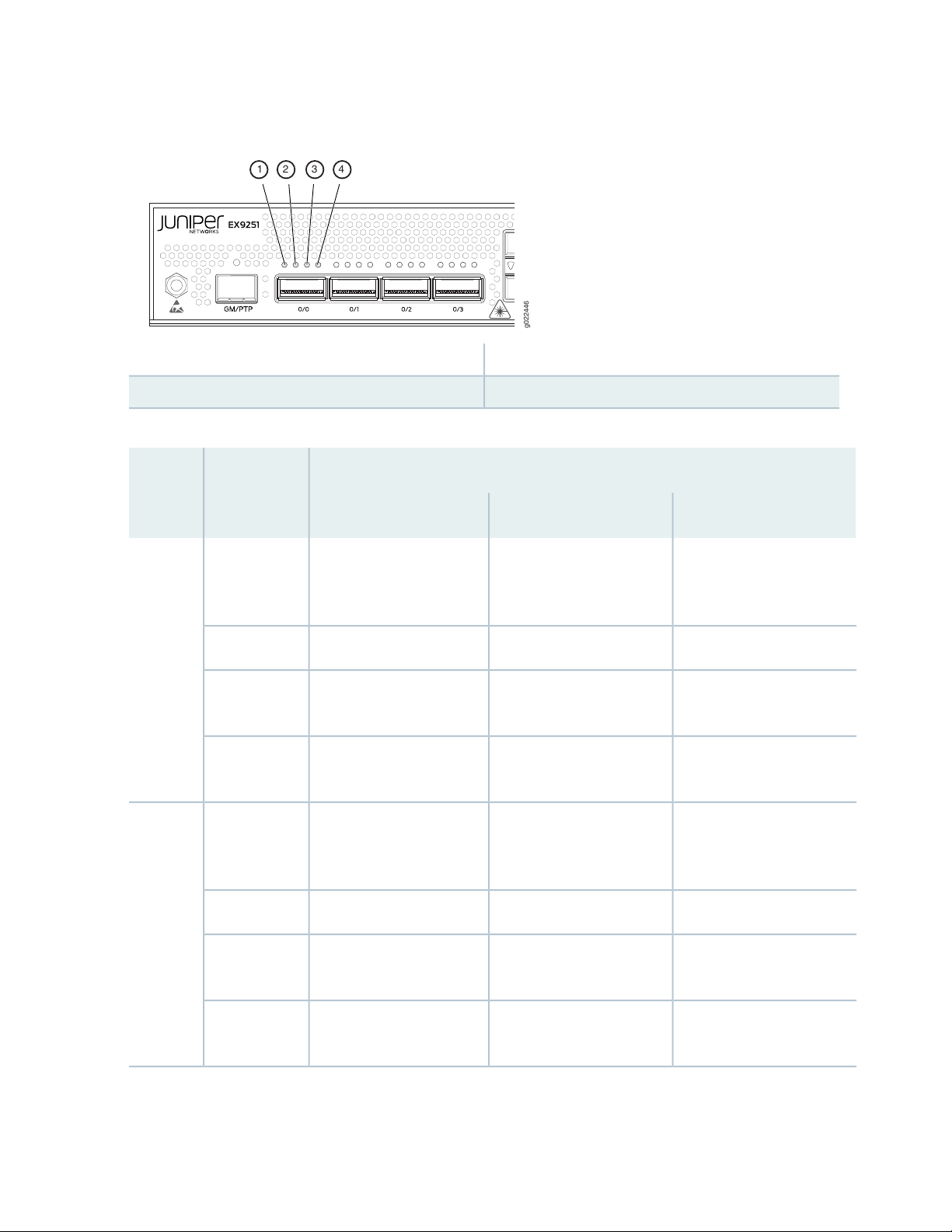
Figure 4: LEDs on the Rate-selectable Ports
g022446
1 2 3 4
3—1— LED2LED0
4—2— LED3LED1
Table 7: Link/Activity LED on the Rate-Selectable Ports
Port Speed
28
Color/StateLED 10G40G100G
GreenLED 0
Amber
Off
A 100G module is plugged
in, the port link is up, and
there is no alarm or failure.
The interface is
administratively disabled.
No 100G module is
plugged in.
A 40G module is plugged in,
the port link is up, and there
is no alarm or failure.
The interface is
administratively disabled.
No 40G module is plugged
in.
Not applicableNot applicableGreenLED 1
Not applicableNot applicableAmber
A 10G module is plugged in,
the port link is up, and there
is no alarm or failure.
The port link is down.The port link is down.The port link is down.Red
The interface is
administratively disabled.
No 10G module is plugged
in.
A 10G module is plugged in,
the port link is up, and there
is no alarm or failure.
The port link is down.Not applicableNot applicableRed
The interface is
administratively disabled.
Not applicableNot applicableOff
No 10G module is plugged
in.
Page 29

Table 7: Link/Activity LED on the Rate-Selectable Ports (continued)
Port Speed
Color/StateLED 10G40G100G
29
Not applicableNot applicableGreenLED 2
Not applicableNot applicableAmber
Not applicableNot applicableOff
Not applicableNot applicableGreenLED 3
Not applicableNot applicableAmber
A 10G module is plugged in,
the port link is up, and there
is no alarm or failure.
The port link is down.Not applicableNot applicableRed
The interface is
administratively disabled.
No 10G module is plugged
in.
A 10G module is plugged in,
the port link is up, and there
is no alarm or failure.
The port link is down.Not applicableNot applicableRed
The interface is
administratively disabled.
Not applicableNot applicableOff
No 10G module is plugged
in.
The eight 10-Gigabit Ethernet SFP+ ports on the front panel of an EX9251 switch has one LED each, which
indicate the link status and activity on the port. Figure 5 on page 30 shows the LEDs on the SFP+ ports
labeled 1/0, 1/2, 1/4, and 1/6. Figure 5 on page 30 shows the LEDs on the SFP+ ports labeled 1/1, 1/3,
1/5, and 1/7. Table 8 on page 30 describes those LEDs.
Page 30
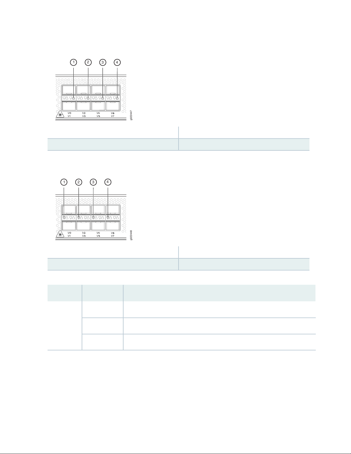
Figure 5: LEDs on the SFP+ Ports Labeled 1/0, 1/2, 1/4, and 1/6
g022447
1 2
3
4
g022448
1 2 3
4
3—1— LED on the port labeled 1/4LED on the port labeled 1/0
4—2— LED on the port labeled 1/6LED on the port labeled 1/2
Figure 6: LEDs on the SFP+ Ports Labeled 1/1, 1/3, 1/5, and 1/7
30
3—1— LED on the port labeled 1/5LED on the port labeled 1/1
4—2— LED on the port labeled 1/7LED on the port labeled 1/3
Table 8: Link/Activity LED on the 10-Gigabit Ethernet SFP+ Ports
State and DescriptionColor/StateLED
The port link is up and there is no alarm or failure.GreenLink activity
The port link is down.Red
The port is not enabled.Off
Figure 7 on page 31 shows the LEDs on the management port and Figure 8 on page 31 shows the LEDs
on the BITS port. Table 9 on page 31 describes the functions of the LEDs on the other ports on the front
panel.
Page 31

Figure 7: LEDs on the Management Port
g022444
1 2
g022445
1 2
Figure 8: LEDs on the BITS Port
31
2—1— Link/Activity LEDSpeed LED
Table 9: Front Panel LEDs
2—1— Link LEDActivity LED
DescriptionStateColorLED
On steadilyGreenONLINE
Both Junos OS and Linux are successfully loaded on the
switch.
The switch is starting Junos OS.Blinking
The switch has loaded Linux.On steadilyRed
The switch is starting Linux.Blinking
The switch is offline.Off–
The switch is functioning normally.On steadilyGreenOK/FAIL
The switch has failed.BlinkingRed
The switch is not powered on.Off–
Page 32

Table 9: Front Panel LEDs (continued)
32
DescriptionStateColorLED
LED on the
MGMT port
On steadilyRedALM
On steadilyYellow
Critical alarm—Indicates a critical condition that can cause
the switch to stop functioning. Possible causes include
component removal, failure, or overheating, or any major
software failure.
Warning alarm—Indicates a serious but nonfatal error
condition, such as a maintenance alert or a significant
increase in component temperature.
There is no alarm.Off–
SSD0 is being accessed by the switch.BlinkingGreenSSD0
SSD0 is not active or not being accessed.Off–
SSD1 is being accessed by the switch.BlinkingGreenSSD1
SSD1 is not active or not being accessed.Off–
The port and the link are active, and there is link activity.BlinkingGreenLink/Activity
The port and the link are active, but there is no link activity.On steadily
on the
MGMT port
on the BITS
port
the BITS port
The port is not active.Off
Link speed is 1000 Mbps.On steadilyGreenSpeed LED
Link speed is 100 Mbps.On steadilyAmber
Link speed is 10 Mbps.Off–
There is no loss (BITS is in locked state).On steadilyGreenActivity LED
There is loss of signal or loss of line.Off–
There is loss of signal or loss of line.On steadilyAmberLink LED on
There is no loss (BITS is in locked state).Off–
Page 33

EX9251 Cooling System
IN THIS SECTION
Fan Trays | 33
Airflow Direction in the EX9251 Switch Chassis | 34
Cooling System in the Power Supplies | 35
Fan Tray Status LEDs | 35
The cooling system components work together to keep all switch components within the acceptable
temperature range.
33
The cooling system in an EX9251 switch consists of three fan trays. Under normal operating conditions,
the fans in the fan trays run at a moderate speed. Temperature sensors inside the chassis monitor the
temperature of the switch components. If a fan fails or the ambient temperature rises above the acceptable
range, the system raises an alarm and the speed of the remaining fans is automatically adjusted to keep
the temperature within the acceptable range. If the ambient maximum temperature is exceeded and the
switch cannot be cooled adequately, the Routing Engine shuts down the switch.
Fan Trays
The fan trays are hot-insertable and hot-removable field-replaceable units (FRUs). The fan trays are installed
on the rear panel of the chassis. Each fan tray contains one counter rotating fan. See Figure 9 on page 34
and Figure 10 on page 34.
Page 34

Figure 9: Fan Tray in an EX9251 Switch
g022403
g022424
1
2 2
Figure 10: Faceplate of a Fan Tray in an EX9251 Switch
34
Airflow Direction in the EX9251 Switch Chassis
The switch has front-to-back (AIR OUT) airflow. The air intake to cool the chassis is through the vents on
the front of the chassis. Air is pulled through the chassis towards the fan tray and hot air exhausts through
the rear of the chassis. See Figure 11 on page 35.
2—1— LatchScrew
Page 35

Figure 11: Airflow Through the EX9251 Switch Chassis
g022410
Ports
FRUs
g022435
1
35
Cooling System in the Power Supplies
The power supplies are self-cooling units. Each power supply has its own built-in fan that cools the power
supply. The power supplies are installed on the rear panel of the switch. The air exhaust for the power
supplies are also located on the rear panel of the chassis.
Fan Tray Status LEDs
The LEDs indicating the state of the fan trays are located adjacent to the fan tray slots on the rear panel
of the chassis (see Figure 12 on page 35).
Figure 12: Fan Tray Status LEDs
1—Fan tray status LEDs
The fan tray status LEDs are bicolor LEDs. Table 10 on page 36 describes the behavior of the fan tray
status LEDs.
Page 36

Table 10: Fan Tray Status LEDs
DescriptionStateColor
Fan tray hardware initialization is complete and software initialization is pending.BlinkingGreen
Software initialization is complete and the fan is functioning normally.On
steadily
36
Red
steadily
Fan tray is faulty and not functioning normally.On
Fan tray is not present.Off–
RELATED DOCUMENTATION
Clearance Requirements for Airflow and Hardware Maintenance for EX9251 Switches | 56
EX9251 Power System
IN THIS SECTION
Power Supplies in an EX9251 Switch | 36
AC Power Cord Specifications for an EX9251 Switch | 42
Power Requirements for EX9251 Switch Components | 44
Power Supply Specifications for EX9251 Switches | 45
Power Supplies in an EX9251 Switch
IN THIS SECTION
AC Power Supply Description | 37
AC Power Supply LEDs and Other Components | 38
Page 37

DC Power Supply Description | 40
DC Power Supply LEDs and Other Components | 40
An EX9251 switch uses either AC or DC power supplies. You can install up to two power supplies in slots
labeled 0 and 1 on the right side of the rear panel of the chassis. The power supply in EX9251 switches is
a hot-insertable and hot-removable field-replaceable unit (FRU). You can install it without powering off
the switch or disrupting the switching function.
The power supplies connect to the PEM board, which distributes the different output voltages produced
by the power supplies to the switch components, depending on their voltage requirements. When both
the power supplies are present, they share power almost equally within a fully populated system. If the
first power supply in a redundant configuration fails or is removed, the second power supply assumes the
entire electrical load without interruption. A single power supply provides the maximum configuration
with full power for as long as the switch is operational. A second power supply can be installed for
redundancy. The chassis is designed to support 1+1 feed redundancy.
37
CAUTION: Do not mix AC and DC power supplies in a switch.
NOTE: The switches are shipped with two power supplies pre-installed on the rear panel.
The power supplies are self-cooling units. Each power supply has its own built-in fan that cools
the power supply.
AC Power Supply Description
Each AC power supply weighs approximately 2.2 lb (1 kg) and has a handle, an ejection lever, an AC
appliance inlet, a fan, and LEDs to monitor the status of the power supply. Figure 13 on page 38 shows
the power supply.
Each power supply requires a dedicated AC power feed and a dedicated customer-site circuit breaker. We
recommend that you use a minimum 20 A (110 VAC) or 16 A (220 VAC) customer-site circuit breaker, or
as required by local code.
Page 38

WARNING: The switch is pluggable type A equipment installed in a restricted-access
g022420
g022421
2
1
3
4
5
6
location. It has a separate protective earthing terminal (sized for 10-32 screws) on the
rear panel of the chassis in addition to the grounding pin of the power supply cord.
This separate protective earthing terminal must be permanently connected to earth.
Figure 13: AC Power Supply in an EX9251 Switch
38
AC Power Supply LEDs and Other Components
Figure 14 on page 38 shows the LEDs and other components on an AC power supply without the AC
power cord retainer installed.
Figure 14: LEDs and Other Components on an AC Power Supply Without the AC Power Cord Retainer
Installed
4—1— Fault LEDHandle
5—2— Ejector leverInput status LED
6—3— AC power cord retainer portOutput status LED
Figure 15 on page 39 shows the LEDs and other components on an AC power supply with the AC power
cord retainer installed.
Page 39

Figure 15: LEDs and Other Components on an AC Power Supply With the AC Power Cord Retainer
g022432
2
1
3
4
6
5
Installed
4—1— Fault LEDHandle
5—2— AC power cord retainerInput status LED
6—3— Ejector leverOutput status LED
Table 11 on page 39 describes the LEDs on the AC power supply.
39
Table 11: AC Power Supply LEDs
DescriptionStateColorLabel
OffUnlitAC OK
On steadilyAmber! (Fault)
The power supply is disconnected from power source, or the
power supply is not receiving power.
Power supply is receiving power.On steadilyGreen
Power supply output is off.OffUnlitDC OK
The power supply is sending out power correctly.On steadilyGreen
An error is detected in the power supply. Replace the power
supply as soon as possible. To maintain proper airflow through
the chassis, leave the power supply installed in the chassis until
you are ready to replace it.
NOTE: If the AC OK LED and the DC OK LED are unlit, either the AC power cord is not installed
properly or the power supply fuse has failed. If the AC OK LED is lit and the DC OK LED is unlit,
the AC power supply is installed properly, but the power supply has an internal failure.
Page 40

DC Power Supply Description
g022422
Each DC power supply weighs approximately 2.2 lb (1 kg) and has a handle, an ejection lever, a fan, LEDs
to monitor the status of the power supply, and a terminal block that provides a single DC input (–48 VDC
and return) that requires a dedicated customer-site circuit breaker. We recommend that you use a dedicated
customer-site circuit breaker rated for 25 A (–48 VDC) minimum, or as required by local code. If you plan
to operate a DC-powered switch at less than the maximum configuration and do not provision a 25 A
(–48 VDC) circuit breaker, we recommend that you provision a dedicated customer-site circuit breaker
for each DC power supply rated for at least 125 percent of the continuous current that the system draws
at –48 VDC.Figure 16 on page 40 shows the power supply.
WARNING: The switch is pluggable type A equipment installed in a restricted-access
location. It has a separate protective earthing terminal (sized for 10-32 screws) on the
rear panel of the chassis. This separate protective earthing terminal must be
permanently connected to earth.
40
Figure 16: DC Power Supply in an EX9251 Switch
DC Power Supply LEDs and Other Components
Figure 17 on page 41 shows the DC power supply status LEDs and other components on a DC power
supply.
Page 41

Figure 17: DC Power Supply LEDs and Other Components on a DC Power Supply
g022423
1 2 3
3—1— Fault LEDInput status LED
2—Output status LED
CAUTION: On the DC power supply, the V+ terminals are shunted internally together,
as are the V– terminals. Terminal with the same polarity can be wired together from
the same source to provide an additional current path in a higher power chassis. Do
not connect the terminals to different sources.
41
Table 12 on page 41 describes the LEDs on the DC power supply.
Table 12: DC Power Supply LEDs
OffUnlitIN (Input)
On steadilyGreen
On steadilyAmber! (Fault)
DescriptionStateColorLabel
The power supply is disconnected from power
source, or the power supply is not receiving
power.
Power supply is receiving power.On steadilyGreen
Power supply output is off.OffUnlitOUT (Output)
The power supply is sending out power
correctly.
An error is detected in the power supply.
Replace the power supply as soon as possible.
To maintain proper airflow through the
chassis, leave the power supply installed in
the chassis until you are ready to replace it.
Page 42

AC Power Cord Specifications for an EX9251 Switch
Each AC power supply has a single AC appliance inlet located on the faceplate that requires a dedicated
AC power feed. A detachable AC power cord is supplied with the AC power supply. The coupler is type
C13 as described by International Electrotechnical Commission (IEC) standard 60320. The plug end of the
power cord fits into the power source outlet that is standard for your geographical location.
Table 13 on page 42 provides specifications and Figure 18 on page 43 depicts the plug on the AC power
cord for some of the countries or regions listed in Table 13 on page 42.
Table 13: AC Power Cord Specifications
Juniper Model NumberPlug StandardsElectrical SpecificationsCountry/Region
CBL-EX-PWR-C13-ARIRAM 2073 Type RA/3250 VAC, 10 A, 50 HzArgentina
42
Switzerland, and United
Kingdom)
Japan
250 VAC, 10 A, 50 HzAustralia
250 VAC, 10 A, 50 HzChina
60 Hz
CBL-EX-PWR-C13-AUAS/NZZS 3112 Type
SAA/3
CBL-EX-PWR-C13-BRNBR 14136 Type BR/3250 VAC, 10 A, 50 HzBrazil
CBL-EX-PWR-C13-CHGB 1002-1996 Type
PRC/3
CBL-EX-PWR-C13-EUCEE (7) VII Type VIIG250 VAC, 10 A, 50 HzEurope (except Italy,
CBL-EX-PWR-C13-INIS 1293 Type IND/3250 VAC, 10 A, 50 HzIndia
CBL-EX-PWR-C13-ILSI 32/1971 Type IL/3G250 VAC, 10 A, 50 HzIsrael
CBL-EX-PWR-C13-ITCEI 23-16 Type I/3G250 VAC, 10 A, 50 HzItaly
CBL-EX-PWR-C13-JPSS-00259 Type VCTF125 VAC, 12 A, 50 Hz or
Korea
60 Hz
250 VAC, 10 A, 50 HzSouth Africa
CBL-EX-PWR-C13-KRCEE (7) VII Type VIIGK250 VAC, 10 A, 50 Hz or
CBL-EX-PWR-C13-USNEMA 5-15 Type N5-15125 VAC, 13 A, 60 HzNorth America
CBL-EX-PWR-C13-SASABS 164/1:1992 Type
ZA/13
Page 43

Table 13: AC Power Cord Specifications (continued)
43
Juniper Model NumberPlug StandardsElectrical SpecificationsCountry/Region
CBL-EX-PWR-C13-SZSEV 6534-2 Type 12G250 VAC, 10 A, 50 HzSwitzerland
Taiwan
Figure 18: AC Plug Types
WARNING: The AC power cord for the switch is intended for use with the switch
only and not for any other use.
WARNING:
125 VAC, 11 A and 15 A,
50 Hz
250 VAC, 10 A, 50 HzUnited Kingdom
CBL-EX-PWR-C13-TWNEMA 5-15P Type
N5-15P
CBL-EX-PWR-C13-UKBS 1363/A Type
BS89/13
Translation from Japanese: The attached power cable is only for this product. Do not
use the cable for another product.
NOTE: In North America, AC power cords must not exceed 4.5 m (approximately 14.75 ft) in
length, to comply with National Electrical Code (NEC) Sections 400-8 (NFPA 75, 5-2.2) and
210-52, and Canadian Electrical Code (CEC) Section 4-010(3). You can order AC power cords
that are in compliance.
Page 44

CAUTION: Ensure that power cords do not touch the switch components, block the
air exhaust and access to switch components, or drape where people could trip on it.
Power Requirements for EX9251 Switch Components
IN THIS SECTION
Power Requirements for EX9251 Switch Components | 44
Calculating System Thermal Output | 45
44
Use the information in this topic to determine the power requirements for your switch.
Power Requirements for EX9251 Switch Components
Table 14 on page 44 lists the power requirements for various hardware components when the switch is
operating under typical and maximum voltage conditions.
Table 14: Power Requirements for Switch Components
Power Requirement
at 25°C (Watts;
Typical)Component
Table 15 on page 44 lists the power requirements for a fully configured AC-powered switch operating
under typical voltage conditions.
Table 15: Power Requirements for an AC-Powered Switch at Typical Temperature (25°C)
Power Requirement at
25°C (Watts)Chassis Configuration
Power Requirement
at 55°C (Watts;
Maximum)
280 W240 WFully loaded switch
Power Requirement
(Watts) with 90%
Efficiency
266 W240 WFully configured chassis running at high activity
Page 45

Table 16 on page 45 lists the power requirements for a fully configured AC-powered switch operating
under maximum voltage conditions.
Table 16: Power Requirements for an AC-Powered Switch at Maximum Temperature (55°C)
Power Requirement
Power Requirement at
55°C (Watts)Chassis Configuration
(Watts) with 90%
Efficiency
311 W280 WFully configured chassis running at high activity
Calculating System Thermal Output
After you have calculated the power consumption for your configuration, you can use that information to
determine the system thermal output (BTUs per hour). To do so, multiply the power consumption in watts
by 3.41.
For example, in Table 15 on page 44, we calculated the power consumption for a fully configured chassis
running at high activity at 25°C typical temperature to be 240 W. Using that information, we can calculate
the system thermal output for the configuration:
45
Power consumption in watts * 3.41 = system thermal output in BTU/hr
240 W * 3.41 = 818.4 BTU/hr
Power Supply Specifications for EX9251 Switches
Table 17 on page 45 lists the AC power system electrical specifications.
Table 17: AC Power System Electrical Specifications
SpecificationsItem
Operating range: 100 through 240 VACAC input voltage
50–60 Hz (nominal)AC input line frequency
AC system current rating
3.2 A @ 100 VAC
•
1.37 A @ 240 VAC
•
312 WAC system input power
Table 18 on page 46 lists the AC power supply electrical specifications.
Page 46

Table 18: AC Power Supply Electrical Specifications
SpecificationsItem
650 WMaximum output power
46
AC input voltage
AC input current rating
Operating range:
100 through 127 VAC
•
200 through 240 VAC
•
50–60 Hz (nominal)AC input line frequency
7.8 A @ 100 VAC
•
3.8 A @ 240 VAC
•
Table 19 on page 46 lists the DC power system electrical specifications.
Table 19: DC Power System Electrical Specifications
SpecificationsItem
Operating range: –44 through –72 VDCDC input voltage
20 A@ –44 VDC (maximum)DC system input current rating
DC system input power
331 W
•
7.75 A @ –44 VDC
•
Table 20 on page 46 lists the DC power supply electrical specifications.
Table 20: DC Power Supply Electrical Specifications
SpecificationsItem
650 WMaximum output power
DC input voltage
Minimum: –44 VDC
•
Nominal: –48 VDC, –60 VDC
•
Operating range: –44 to –72 VDC
•
20 A @ –44 VDCDC input current rating
Page 47

2
CHAPTER
Site Planning, Preparation, and
Specifications
Site Preparation Checklist for an EX9251 Switch | 48
EX9251 Site Guidelines and Requirements | 49
EX9251 Network Cable and Transceiver Planning | 60
EX9251 Management Cable Specifications and Pinouts | 68
Page 48

Site Preparation Checklist for an EX9251 Switch
The checklist in Table 21 on page 48 summarizes the tasks you need to perform to prepare a site for
installing an EX9251 switch.
Table 21: Site Preparation Checklist
Performed
byFor More InformationItem or Task
Environment
48
Date
Verify that environmental factors such
as temperature and humidity do not
exceed switch tolerances.
Power
Measure distance between external
power sources and switch installation
site.
Calculate the power consumption and
requirements.
“Environmental Requirements and Specifications for
EX Series Switches” on page 49
“Power Supply Specifications for EX9251 Switches”
on page 45
“Power Requirements for EX9251 Switch
Components” on page 44
“Calculating the Fiber-Optic Cable Power Budget for
EX Series Devices” on page 66
“Calculating the Fiber-Optic Cable Power Margin for
EX Series Devices” on page 66
Rack or Cabinet
Select the type of rack or cabinet and
verify that it meets the minimum
requirements for the installation of the
switch.
Plan rack or cabinet location, ensuring
the required space clearances.
Secure the rack or cabinet to the floor
and building structure.
“Rack and Cabinet Requirements for EX9251
Switches” on page 57
“Clearance Requirements for Airflow and Hardware
Maintenance for EX9251 Switches” on page 56
Page 49

Table 21: Site Preparation Checklist (continued)
Cables
Performed
byFor More InformationItem or Task
49
Date
Plan the cable routing and management.
Acquire cables and connectors:
Determine the number of cables
•
needed based on your planned
configuration.
Ensure that the distance between
•
hardware components to be
connected allows for cable lengths
to be within the specified maximum
limits.
“Management Cable Specifications” on page 69
“Specifications of Cables and Wires That Connect to
Ports on the Front Panel in an EX9251 Switch” on
page 69
EX9251 Site Guidelines and Requirements
IN THIS SECTION
Environmental Requirements and Specifications for EX Series Switches | 49
General Site Guidelines | 54
Site Electrical Wiring Guidelines | 55
Clearance Requirements for Airflow and Hardware Maintenance for EX9251 Switches | 56
Rack and Cabinet Requirements for EX9251 Switches | 57
Environmental Requirements and Specifications for EX Series Switches
The switch must be installed in a rack or cabinet housed in a dry, clean, well-ventilated, and
temperature-controlled environment.
Page 50

Ensure that these environmental guidelines are followed:
The site must be as dust-free as possible, because dust can clog air intake vents and filters, reducing the
•
efficiency of the switch cooling system.
Maintain ambient airflow for normal switch operation. If the airflow is blocked or restricted, or if the
•
intake air is too warm, the switch might overheat, leading to the switch temperature monitor shutting
down the switch to protect the hardware components.
Table 22 on page 50 provides the required environmental conditions for normal switch operation.
Table 22: EX Series Switch Environmental Tolerances
Environment Tolerance
Switch or
device SeismicTemperatureRelative HumidityAltitude
50
EX2200-C
EX2200
(except
EX2200-C
switches)
EX2300-C
No performance
degradation up to
5,000 feet (1524
meters)
No performance
degradation up to
10,000 feet
(3048 meters)
No performance
degradation up to
5,000 feet
(1524 meters)
Normal operation ensured
in the relative humidity
range 10% through 85%
(noncondensing)
Normal operation ensured
in the relative humidity
range 10% through 85%
(noncondensing)
Normal operation ensured
in the relative humidity
range 10% through 85%
(noncondensing)
Normal operation ensured
in the temperature range
32° F (0° C) through 104°
F (40° C) at altitudes up to
5,000 ft (1,524 m).
For information about
extended temperature SFP
transceivers supported on
EX2200 switches, see
Pluggable Transceivers
Supported on EX2200
Switches.
Normal operation ensured
in the temperature range
32° F (0° C) through 113°
F (45° C)
Normal operation ensured
in the temperature range
32° F (0° C) through 104°
F (40° C)
Complies with Zone
4 earthquake
requirements as per
GR-63, Issue 4.
Complies with Zone
4 earthquake
requirements as per
GR-63, Issue 4.
Complies with Zone
4 earthquake
requirements as per
GR-63, Issue 4.
EX2300
(except
EX2300-C
switches)
No performance
degradation up to
13,000 feet
(3962 meters) at
104° F (40° C) as
per GR-63
Normal operation ensured
in the relative humidity
range 10% through 85%
(noncondensing)
Normal operation ensured
in the temperature range
32° F (0° C) through 113°
F (45° C)
Complies with Zone
4 earthquake
requirements as per
GR-63, Issue 4.
Page 51

Table 22: EX Series Switch Environmental Tolerances (continued)
Environment Tolerance
Switch or
device SeismicTemperatureRelative HumidityAltitude
51
EX3200
EX3300
EX3400
EX4200
EX4300
The
maximum
thermal
output for
EX4300-48T
is 423
BTU/hour
and for
EX4300-48P
is 5844
BTU/hour.
No performance
degradation up to
10,000 feet
(3048 meters)
No performance
degradation up to
10,000 feet
(3048 meters)
No performance
degradation up to
10,000 feet
(3048 meters)
No performance
degradation up to
10,000 feet
(3048 meters)
EX4300 switches
except the
EX4300-48MP
model— No
performance
degradation up to
10,000 feet
(3048 meters)
EX4300-48MP
model— No
performance
degradation up to
6,000 feet
(1829 meters)
Normal operation ensured
in the relative humidity
range 10% through 85%
(noncondensing)
Normal operation ensured
in the relative humidity
range 10% through 85%
(noncondensing)
Normal operation ensured
in the relative humidity
range 10% through 85%
(noncondensing)
Normal operation ensured
in the relative humidity
range 10% through 85%
(noncondensing)
EX4300 switches except
the EX4300-48MP
model— Normal operation
ensured in the relative
humidity range 10%
through 85%
(noncondensing)
EX4300-48MP model—
Normal operation ensured
in the relative humidity
range 5% through 90%
(noncondensing)
Normal operation ensured
in the temperature range
32° F (0° C) through 113°
F (45° C)
Normal operation ensured
in the temperature range
32° F (0° C) through 113°
F (45° C)
Normal operation ensured
in the temperature range
32° F (0° C) through 113°
F (45° C)
Normal operation ensured
in the temperature range
32° F (0° C) through 113°
F (45° C)
Normal operation ensured
in the temperature range
32° F (0° C) through 113°
F (45° C)
Complies with Zone
4 earthquake
requirements as per
GR-63, Issue 4.
Complies with Zone
4 earthquake
requirements as per
GR-63, Issue 4.
Complies with Zone
4 earthquake
requirements as per
GR-63, Issue 4.
Complies with Zone
4 earthquake
requirements as per
GR-63, Issue 4.
Complies with Zone
4 earthquake
requirements as per
GR-63, Issue 4.
EX4500
No performance
degradation up to
10,000 feet
(3048 meters)
Normal operation ensured
in the relative humidity
range 10% through 85%
(noncondensing)
Normal operation ensured
in the temperature range
32° F (0° C) through 113°
F (45° C)
Complies with Zone
4 earthquake
requirements as per
GR-63, Issue 4.
Page 52

Table 22: EX Series Switch Environmental Tolerances (continued)
Environment Tolerance
Switch or
device SeismicTemperatureRelative HumidityAltitude
52
EX4550
EX4600
No performance
degradation up to
10,000 feet
(3048 meters)
No performance
degradation to
6,562 feet
(2000 meters)
Normal operation ensured
in the relative humidity
range 10% through 85%
(noncondensing)
Normal operation ensured
in the relative humidity
range 5% through 90%,
noncondensing
Short-term operation
•
ensured in the relative
humidity range 5%
through 93%,
noncondensing
NOTE: As defined in
NEBS GR-63-CORE,
Issue 4, short-term
events can be up to 96
hours in duration but
not more than 15 days
per year.
EX4550-32F switches—
•
Normal operation
ensured in the
temperature range 32°
F (0° C) through 113° F
(45° C)
EX4550-32T switches—
•
Normal operation is
ensured in the
temperature range 32°
F through 104° F (40° C)
Normal operation
•
ensured in the
temperature range 32°
F (0° C) through 113° F
(45° C)
Nonoperating storage
•
temperature in shipping
container: – 40° F
(–40° C) through 158° F
(70° C)
Complies with Zone
4 earthquake
requirements as per
GR-63, Issue 4.
Complies with Zone
4 earthquake
requirements per
NEBS GR-63-CORE,
Issue 4.
EX4650
EX6210
No performance
degradation to
6,000 feet
(1829 meters)
No performance
degradation up to
10,000 feet
(3048 meters)
Normal operation ensured
in the relative humidity
range 10% through 85%
(condensing)
Normal operation ensured
in the relative humidity
range 10% through 85%
(noncondensing)
Normal operation is ensured
in the temperature range
32° F (0° C) through 104°
F (40° C)
Normal operation is ensured
in the temperature range
32° F (0° C) through 104°
F (40° C)
Complies with Zone
4 earthquake
requirements as per
GR-63, Issue 4.
Complies with Zone
4 earthquake
requirements as per
GR-63, Issue 4.
Page 53

Table 22: EX Series Switch Environmental Tolerances (continued)
Environment Tolerance
Switch or
device SeismicTemperatureRelative HumidityAltitude
53
EX8208
EX8216
EX9204
EX9208
No performance
degradation up to
10,000 feet
(3048 meters)
No performance
degradation up to
10,000 feet
(3048 meters)
No performance
degradation up to
10,000 feet
(3048 meters)
No performance
degradation up to
10,000 feet
(3048 meters)
Normal operation ensured
in the relative humidity
range 10% through 85%
(noncondensing)
Normal operation ensured
in the relative humidity
range 10% through 85%
(noncondensing)
Normal operation ensured
in the relative humidity
range 5% through 90%
(noncondensing)
Normal operation ensured
in the relative humidity
range 5% through 90%
(noncondensing)
Normal operation is ensured
in the temperature range
32° F (0° C) through 104°
F (40° C)
Normal operation is ensured
in the temperature range
32° F (0° C) through 104°
F (40° C)
Normal operation is ensured
in the temperature range
32° F (0° C) through 104°
F (40° C)
Nonoperating storage
temperature in shipping
container: – 40° F (–40° C)
to 158° F (70° C)
Normal operation is ensured
in the temperature range
32° F (0° C) through 104°
F (40° C)
Complies with Zone
4 earthquake
requirements as per
GR-63, Issue 4.
Complies with Zone
4 earthquake
requirements as per
GR-63, Issue 4.
Complies with Zone
4 earthquake
requirements as per
GR-63.
Complies with Zone
4 earthquake
requirements as per
GR-63.
EX9214
No performance
degradation up to
10,000 feet
(3048 meters)
Normal operation ensured
in the relative humidity
range 5% through 90%
(noncondensing)
Nonoperating storage
temperature in shipping
container: – 40° F (–40° C)
to 158° F (70° C)
Normal operation is ensured
in the temperature range
32° F (0° C) through 104°
F (40° C)
Nonoperating storage
temperature in shipping
container: – 40° F (–40° C)
through 158° F (70° C)
Complies with Zone
4 earthquake
requirements as per
GR-63.
Page 54

Table 22: EX Series Switch Environmental Tolerances (continued)
Environment Tolerance
Switch or
device SeismicTemperatureRelative HumidityAltitude
54
EX9251
The
maximum
thermal
output is
1705
BTU/hour
(500 W).
XRE200
No performance
degradation up to
10,000 ft (3048 m)
No performance
degradation up to
10,000 feet
(3048 meters)
Normal operation ensured
in relative humidity range
of 5% to 90%,
noncondensing
Normal operation ensured
in the relative humidity
range 10% through 85%
(noncondensing)
Normal operation ensured
in temperature range of 32°
F (0° C) to 104° F (40° C)
Nonoperating storage
temperature in shipping
container: – 40° F (–40° C)
to 158° F (70° C)
Normal operation ensured
in the temperature range
41° F (5° C) through 104°
F (40° C)
Complies with
Telcordia
Technologies Zone
4 earthquake
requirements
Complies with Zone
4 earthquake
requirements as per
GR-63, Issue 4.
NOTE: Install EX Series switches only in restricted areas, such as dedicated equipment rooms
and equipment closets, in accordance with Articles 110– 16, 110– 17, and 110– 18 of the
National Electrical Code, ANSI/NFPA 70.
General Site Guidelines
Efficient device operation requires proper site planning and maintenance and proper layout of the equipment,
rack or cabinet, and wiring closet.
To plan and create an acceptable operating environment for your device and prevent environmentally
caused equipment failures:
Keep the area around the chassis free from dust and conductive material, such as metal flakes.
•
Follow prescribed airflow guidelines to ensure that the cooling system functions properly and that
•
exhaust from other equipment does not blow into the intake vents of the device.
Follow the prescribed electrostatic discharge (ESD) prevention procedures to prevent damaging the
•
equipment. Static discharge can cause components to fail completely or intermittently over time.
Install the device in a secure area, so that only authorized personnel can access the device.
•
Page 55

Site Electrical Wiring Guidelines
Table 23 on page 55 describes the factors you must consider while planning the electrical wiring at your
site.
WARNING: You must provide a properly grounded and shielded environment and use
electrical surge-suppression devices.
Avertissement Vous devez établir un environnement protégé et convenablement mis
à la terre et utiliser des dispositifs de parasurtension.
Table 23: Site Electrical Wiring Guidelines
Site Wiring
Factor
Guidelines
55
Signaling
limitations
Radio
frequency
interference
Electromagnetic
compatibility
If your site experiences any of the following problems, consult experts in electrical surge suppression
and shielding:
Improperly installed wires cause radio frequency interference (RFI).
•
Damage from lightning strikes occurs when wires exceed recommended distances or pass between
•
buildings.
Electromagnetic pulses (EMPs) caused by lightning damage unshielded conductors and electronic
•
devices.
To reduce or eliminate RFI from your site wiring, do the following:
Use a twisted-pair cable with a good distribution of grounding conductors.
•
If you must exceed the recommended distances, use a high-quality twisted-pair cable with one
•
ground conductor for each data signal when applicable.
If your site is susceptible to problems with electromagnetic compatibility (EMC), particularly from
lightning or radio transmitters, seek expert advice.
Some of the problems caused by strong sources of electromagnetic interference (EMI) are:
Destruction of the signal drivers and receivers in the device
•
Electrical hazards as a result of power surges conducted over the lines into the equipment
•
Page 56

Clearance Requirements for Airflow and Hardware Maintenance for EX9251
g022410
Ports
FRUs
Switches
When planning the site for installing an EX9251 switch, you must ensure sufficient clearance around the
switch.
Follow these clearance requirements:
For the cooling system to function properly, the airflow around the chassis must be unrestricted. See
•
Figure 19 on page 56 for reference.
Figure 19: Airflow Through the EX9251 Switch Chassis
56
If you are mounting the switch on a rack or cabinet along with other equipment, ensure that the exhaust
•
from other equipment does not blow into the intake vents of the chassis.
Leave at least 6 in. (15.2 cm) clearance in front of and behind the chassis for airflow.
•
Leave at least 6 in. (15.2 cm) clearance on the left of the chassis for installing the grounding lug.
•
Leave at least 24 in. (61 cm) clearance in front of and behind the switch for service personnel to remove
•
and install hardware components. NEBS GR-63 recommends that you allow at least 30 in. (76.2 cm) in
front of the rack or cabinet and 24 in. (61 cm) behind the rack or cabinet. See Figure 20 on page 57.
Page 57

Figure 20: Clearance Requirements for Airflow and Hardware Maintenance for an EX9251 Switch Chassis
g022411
18.99 in.
(4 8 .23 cm)
Clea ran c e requi red
for main t enan c e
24 in. ( 6 1 cm)
20 .41 in. ( 51.84 cm)
FRUsPorts
18.99 in.
(4 8.23 cm)
Clea ran c e requi red
for main t enan c e
24 in. ( 6 1 cm)
57
Rack and Cabinet Requirements for EX9251 Switches
You can mount an EX9251 switch on four-posts of a 19-in rack or an ETSI rack or in a cabinet that contains
a 19-in. rack or an ETSI rack.
Rack requirements consist of:
Rack type
•
Mounting bracket hole spacing
•
Rack size and strength
•
Rack connection to the building structure
•
Table 24 on page 57 provides the rack requirements and specifications.
Table 24: Rack Requirements and Specifications
GuidelinesRack Requirement
Rack type
You can mount the device on a rack that provides bracket holes or hole patterns
spaced at 1 U (1.75 in. or 4.45 cm) increments and meets the size and strength
requirements to support the weight.
A U is the standard rack unit defined by the Electronic Components Industry
Association (http://www.ecianow.org).
Page 58

Table 24: Rack Requirements and Specifications (continued)
GuidelinesRack Requirement
58
Mounting bracket hole spacing
Rack size and strength
Rack connection to building
structure
The holes in the mounting brackets are spaced at 1 U (1.75 in. or 4.45 cm), so
that the device can be mounted in any rack that provides holes spaced at that
distance.
Ensure that the rack complies with the size and strength standards of a 19-in.
•
rack as defined by the Electronic Components Industry Association
(http://www.ecianow.org) or with the size and strength standards of an ETSI
rack as defined in the European Telecommunications Standards Institute (ETS
300 119) published by the European Telecommunications Standards Institute
(ETSI).
Ensure that the rack rails are spaced widely enough to accommodate the
•
external dimensions of the device chassis. The outer edges of the front-mounting
brackets extend the width of the chassis to 19 in. (48.2 cm).
The rack must be strong enough to support the weight of the device.
•
Ensure that the spacing of rails and adjacent racks provides for proper clearance
•
around the device and rack.
Secure the rack to the building structure.
•
If earthquakes are a possibility in your geographical area, secure the rack to the
•
floor.
Secure the rack to the ceiling brackets as well as wall or floor brackets for
•
maximum stability.
Cabinet requirements consist of:
Cabinet size
•
Clearance requirements
•
Cabinet airflow requirements
•
Table 25 on page 59 provides the cabinet requirements and specifications.
Page 59

Table 25: Cabinet Requirements and Specifications
Cabinet
Requirement
Guidelines
59
Cabinet size
Cabinet clearance
Cabinet airflow
requirements
You can mount the device in a cabinet that contains a 19-in. rack as defined by the Electronic
•
Components Industry Association (http://www.ecianow.org) or an ETSI rack as defined in
the European Telecommunications Standards Institute (ETS 300 119) published by the
European Telecommunications Standards Institute (ETSI).
The minimum cabinet size must be able to accommodate the maximum external dimensions
•
of the device.
The minimum total clearance inside the cabinet is 30 in. (76.2 cm) between the inside of the
front door and the inside of the rear door.
When you mount the device in a cabinet, ensure that ventilation through the cabinet is
sufficient to prevent overheating.
Ensure adequate cool air supply to dissipate the thermal output of the device or devices.
•
Ensure that the hot air exhaust of the chassis exits the cabinet without recirculating into
•
the device. An open cabinet (without a top or doors) that employs hot air exhaust extraction
from the top ensures the best airflow through the chassis. If the cabinet contains a top or
doors, perforations in these elements assist with removing the hot air exhaust.
Install the device in the cabinet in a way that maximizes the open space on the side of the
•
chassis that has the hot air exhaust.
Route and dress all cables to minimize the blockage of airflow to and from the chassis.
•
Ensure that the spacing of rails and adjacent cabinets is such that there is proper clearance
•
around the device and cabinet.
A cabinet larger than the minimum required provides better airflow and reduces the chance
•
of overheating.
SEE ALSO
Rack-Mounting and Cabinet-Mounting Warnings | 179
Page 60

EX9251 Network Cable and Transceiver Planning
IN THIS SECTION
Pluggable Transceivers Supported on EX9251 Switches | 60
SFP+ Direct Attach Copper Cables for EX Series Switches | 61
QSFP+ Direct Attach Copper Cables for EX Series Switches | 63
Understanding EX Series Switches Fiber-Optic Cable Signal Loss, Attenuation, and Dispersion | 64
Calculating the Fiber-Optic Cable Power Budget for EX Series Devices | 66
Calculating the Fiber-Optic Cable Power Margin for EX Series Devices | 66
60
Pluggable Transceivers Supported on EX9251 Switches
The network ports on the front panel in EX9251 switches support transceivers. You can find the list of
transceivers supported on EX9251 switches and information about those transceivers in the Hardware
Compatibility Tool page for EX9251.
NOTE: We recommend that you use only optical transceivers and optical connectors purchased
from Juniper Networks with your Juniper Networks device.
CAUTION: If you face a problem running a Juniper Networks device that uses a
third-party optic or cable, the Juniper Networks Technical Assistance Center (JTAC)
can help you diagnose the source of the problem. Your JTAC engineer might recommend
that you check the third-party optic or cable and potentially replace it with an equivalent
Juniper Networks optic or cable that is qualified for the device.
The Gigabit Ethernet transceivers installed in EX9251 switches support digital optical monitoring (DOM).
You can view the diagnostic details for these transceivers by issuing the operational mode CLI command
show interfaces diagnostics optics.
SEE ALSO
Page 61

Install a Transceiver | 108
Install a QSFP28 Transceiver | 142
Remove a Transceiver | 135
Remove a QSFP28 Transceiver | 140
EX9251 Switch Hardware Overview | 19
SFP+ Direct Attach Copper Cables for EX Series Switches
IN THIS SECTION
Cable Specifications | 62
List of DAC Cables Supported on EX Series Switches | 62
Standards Supported by These Cables | 63
61
Small form-factor pluggable plus transceiver (SFP+) direct attach copper (DAC) cables, also known as
Twinax cables, are suitable for in-rack connections between servers and switches. They are suitable for
short distances, making them ideal for highly cost-effective networking connectivity within a rack and
between adjacent racks.
NOTE: We recommend that you use only SFP+ DAC cables purchased from Juniper Networks
with your Juniper Networks device.
CAUTION: If you face a problem running a Juniper Networks device that uses a
third-party optic or cable, the Juniper Networks Technical Assistance Center (JTAC)
can help you diagnose the source of the problem. Your JTAC engineer might recommend
that you check the third-party optic or cable and potentially replace it with an equivalent
Juniper Networks optic or cable that is qualified for the device.
Page 62

Cable Specifications
EX Series switches support SFP+ passive DAC cables. The passive Twinax cable is a straight cable with
no active electronic components. EX Series switches support 1 m, 3 m, 5 m, and 7 m long SFP+ passive
DAC cables. See Figure 21 on page 62.
Figure 21: SFP+ Direct Attach Copper Cables for EX Series Switches
The cables are hot-removable and hot-insertable: You can remove and replace them without powering
off the switch or disrupting switch functions. A cable comprises a low-voltage cable assembly that connects
directly into two 10-Gigabit Ethernet ports, one at each end of the cable. The cables use high-performance
integrated duplex serial data links for bidirectional communication and are designed for data rates of up
to 10 Gbps.
62
List of DAC Cables Supported on EX Series Switches
For the list of DAC cables supported on EX Series switches and the specifications of these cables, see:
EX2300—Hardware Compatibility Tool page for EX2300
•
EX3200—Hardware Compatibility Tool page for EX3200
•
EX3300—Hardware Compatibility Tool page for EX3300
•
EX3400—Hardware Compatibility Tool page for EX3400
•
EX4200—Hardware Compatibility Tool page for EX4200
•
EX4300—Hardware Compatibility Tool page for EX4300
•
EX4500—Hardware Compatibility Tool page for EX4500
•
EX4550—Hardware Compatibility Tool page for EX4550
•
EX4600—Hardware Compatibility Tool page for EX4600
•
EX8208—Hardware Compatibility Tool page for EX8208
•
EX8216—Hardware Compatibility Tool page for EX8216
•
EX9251—Hardware Compatibility Tool page for EX9251
•
EX9253—Hardware Compatibility Tool page for EX9253
•
Page 63

Standards Supported by These Cables
The cables comply with the following standards:
SFP mechanical standard SFF-843— see ftp://ftp.seagate.com/sff/SFF-8431.PDF.
•
Electrical interface standard SFF-8432— see ftp://ftp.seagate.com/sff/SFF-8432.PDF.
•
SFP+ Multi-Source Alliance (MSA) standards
•
QSFP+ Direct Attach Copper Cables for EX Series Switches
IN THIS SECTION
Cable Specifications | 64
63
DAC Cables Supported on EX3400, EX4300, EX4550, EX4600, EX9251, and EX9253 Switches | 64
Quad small form-factor pluggable plus (QSFP+) direct attach copper (DAC) cables are suitable for in-rack
connections between QSFP+ ports on EX3400, EX4300, EX4550, EX4600, EX9251, and EX9253 switches.
They are suitable for short distances, making them ideal for highly cost-effective networking connectivity
within a rack and between adjacent racks.
NOTE: We recommend that you use only QSFP+ DAC cables purchased from Juniper Networks
with your Juniper Networks device.
CAUTION: If you face a problem running a Juniper Networks device that uses a
third-party optic or cable, the Juniper Networks Technical Assistance Center (JTAC)
can help you diagnose the source of the problem. Your JTAC engineer might recommend
that you check the third-party optic or cable and potentially replace it with an equivalent
Juniper Networks optic or cable that is qualified for the device.
Page 64

Cable Specifications
QSFP+ passive DAC cables are hot-removable and hot-insertable. A cable consists of a cable assembly
that connects directly into two QSFP+ modules, one at each end of the cable. The cables use integrated
duplex serial data links for bidirectional communication and are designed for data rates up to 40 Gbps.
Passive DAC cables have no signal amplification built into the cable assembly. See Figure 22 on page 64.
Figure 22: QSFP+ Direct Attach Copper Cables
DAC Cables Supported on EX3400, EX4300, EX4550, EX4600, EX9251, and EX9253 Switches
For the list of DAC cables supported on EX3400, EX4300, EX4550, EX4600, EX9251, and EX9253 switches
and the specifications of these cables, see:
64
EX3400—Hardware Compatibility Tool page for EX3400
•
EX4300—Hardware Compatibility Tool page for EX4300
•
EX4550—Hardware Compatibility Tool page for EX4550
•
EX4600—Hardware Compatibility Tool page for EX4600
•
EX9251—Hardware Compatibility Tool page for EX9251
•
EX9253—Hardware Compatibility Tool page for EX9253
•
Understanding EX Series Switches Fiber-Optic Cable Signal Loss, Attenuation, and Dispersion
IN THIS SECTION
Signal Loss in Multimode and Single-Mode Fiber-Optic Cable | 65
Attenuation and Dispersion in Fiber-Optic Cable | 65
Page 65

To determine the power budget and power margin needed for fiber-optic connections, you need to
understand how signal loss, attenuation, and dispersion affect transmission. EX Series switches use various
types of network cable, including multimode and single-mode fiber-optic cable.
Signal Loss in Multimode and Single-Mode Fiber-Optic Cable
Multimode fiber is large enough in diameter to allow rays of light to reflect internally (bounce off the walls
of the fiber). Interfaces with multimode optics typically use LEDs as light sources. However, LEDs are not
coherent light sources. They spray varying wavelengths of light into the multimode fiber, which reflects
the light at different angles. Light rays travel in jagged lines through a multimode fiber, causing signal
dispersion. When light traveling in the fiber core radiates into the fiber cladding (layers of lower refractive
index material in close contact with a core material of higher refractive index), higher-order mode loss
(HOL) occurs. Together, these factors reduce the transmission distance of multimode fiber compared to
that of single-mode fiber.
Single-mode fiber is so small in diameter that rays of light reflect internally through one layer only. Interfaces
with single-mode optics use lasers as light sources. Lasers generate a single wavelength of light, which
travels in a straight line through the single-mode fiber. Compared to multimode fiber, single-mode fiber
has a higher bandwidth and can carry signals for longer distances. It is consequently more expensive.
65
Exceeding the maximum transmission distances can result in significant signal loss, which causes unreliable
transmission.
Attenuation and Dispersion in Fiber-Optic Cable
An optical data link functions correctly provided that modulated light reaching the receiver has enough
power to be demodulated correctly. Attenuation is the reduction in strength of the light signal during
transmission. Passive media components such as cables, cable splices, and connectors cause attenuation.
Although attenuation is significantly lower for optical fiber than for other media, it still occurs in both
multimode and single-mode transmission. An efficient optical data link must transmit enough light to
overcome attenuation.
Dispersion is the spreading of the signal over time. The following two types of dispersion can affect signal
transmission through an optical data link:
Chromatic dispersion, which is the spreading of the signal over time caused by the different speeds of
•
light rays.
Modal dispersion, which is the spreading of the signal over time caused by the different propagation
•
modes in the fiber.
For multimode transmission, modal dispersion, rather than chromatic dispersion or attenuation, usually
limits the maximum bit rate and link length. For single-mode transmission, modal dispersion is not a factor.
However, at higher bit rates and over longer distances, chromatic dispersion limits the maximum link length.
Page 66

An efficient optical data link must have enough light to exceed the minimum power that the receiver
requires to operate within its specifications. In addition, the total dispersion must be within the limits
specified for the type of link in Telcordia Technologies document GR-253-CORE (Section 4.3) and
International Telecommunications Union (ITU) document G.957.
When chromatic dispersion is at the maximum allowed, its effect can be considered as a power penalty in
the power budget. The optical power budget must allow for the sum of component attenuation, power
penalties (including those from dispersion), and a safety margin for unexpected losses.
Calculating the Fiber-Optic Cable Power Budget for EX Series Devices
To ensure that fiber-optic connections have sufficient power for correct operation, calculate the link's
power budget when planning fiber-optic cable layout and distances to ensure that fiber-optic connections
have sufficient power for correct operation. The power budget is the maximum amount of power the link
can transmit. When you calculate the power budget, you use a worst-case analysis to provide a margin of
error, even though all the parts of an actual system do not operate at the worst-case levels.
66
To calculate the worst-case estimate for fiber-optic cable power budget (PB) for the link:
1. Determine values for the link's minimum transmitter power (PT) and minimum receiver sensitivity (PR).
For example, here, (PT) and (PR) are measured in decibels, and decibels are referred to one milliwatt
(dBm).
PT= – 15 dBm
PR= – 28 dBm
NOTE: See the specifications for your transmitter and receiver to find the minimum transmitter
power and minimum receiver sensitivity.
2. Calculate the power budget (PB) by subtracting (PR) from (PT):
– 15 dBm – (–28 dBm) = 13 dBm
Calculating the Fiber-Optic Cable Power Margin for EX Series Devices
Calculate the link's power margin when planning fiber-optic cable layout and distances to ensure that
fiber-optic connections have sufficient signal power to overcome system losses and still satisfy the minimum
Page 67

input requirements of the receiver for the required performance level. The power margin (PM) is the amount
of power available after attenuation or link loss (LL) has been subtracted from the power budget (PB).
When you calculate the power margin, you use a worst-case analysis to provide a margin of error, even
though all the parts of an actual system do not operate at worst-case levels. A power margin (PM) greater
than zero indicates that the power budget is sufficient to operate the receiver and that it does not exceed
the maximum receiver input power. This means the link will work. A (PM) that is zero or negative indicates
insufficient power to operate the receiver. See the specification for your receiver to find the maximum
receiver input power.
Before calculating the power margin:
Calculate the power budget (see “Calculating the Fiber-Optic Cable Power Budget for EX Series Devices”
•
on page 66).
To calculate the worst-case estimate for the power margin (PM) for the link:
1. Determine the maximum value for link loss (LL) by adding estimated values for applicable link-loss
factors—for example, use the sample values for various factors as provided in Table 26 on page 67
(here, the link is 2 km long and multimode, and the (PB) is 13 dBm):
67
Table 26: Estimated Values for Factors Causing Link Loss
Higher-order mode losses (HOL)
Modal and chromatic dispersion
Multimode—0.5 dBm
•
Single mode—None
•
Multimode—None, if product of
•
bandwidth and distance is less than
500 MHz/km
Single mode—None
•
0.5 dBmConnector
0.5 dBmSplice
Sample (LL) Calculation ValuesEstimated Link-Loss ValueLink-Loss Factor
0.5 dBm
•
0 dBm
•
0 dBm
•
0 dBm
•
This example assumes 5 connectors.
Loss for 5 connectors:
(5) * (0.5 dBm) = 2.5 dBm
This example assumes 2 splices. Loss for
two splices:
(2) * (0.5 dBm) = 1 dBm
Fiber attenuation
Multimode—1 dBm/km
•
Single mode—0.5 dBm/km
•
This example assumes the link is 2 km
long. Fiber attenuation for 2 km:
(2 km) * (1.0 dBm/km) = 2 dBm
•
(2 km) * (0.5 dBm/km) = 1 dBm
•
Page 68

Table 26: Estimated Values for Factors Causing Link Loss (continued)
NOTE: For information about the actual amount of signal loss caused by equipment and
other factors, see your vendor documentation for that equipment.
2. Calculate the (PM) by subtracting (LL) from (PB):
68
Sample (LL) Calculation ValuesEstimated Link-Loss ValueLink-Loss Factor
1 dBm1 dBmClock Recovery Module (CRM)
PB– LL = P
M
(13 dBm) – (0.5 dBm [HOL]) – ((5) * (0.5 dBm)) – ((2) * (0.5 dBm)) – ((2 km) * (1.0 dBm/km)) – (1 dB
[CRM]) = P
13 dBm – 0.5 dBm – 2.5 dBm – 1 dBm – 2 dBm – 1 dBm = P
M
M
PM= 6 dBm
The calculated power margin is greater than zero, indicating that the link has sufficient power for
transmission. Also, the power margin value does not exceed the maximum receiver input power. Refer
to the specification for your receiver to find the maximum receiver input power.
EX9251 Management Cable Specifications and Pinouts
IN THIS SECTION
Management Cable Specifications | 69
Specifications of Cables and Wires That Connect to Ports on the Front Panel in an EX9251 Switch | 69
Grounding Cable and Lug Specifications for EX9251 Switches | 70
USB Port Specifications for an EX Series Switch | 71
Console Port Connector Pinout Information for an EX9251 Switch | 72
RJ-45 to DB-9 Serial Port Adapter Pinout Information | 73
RJ-45 Management Port Connector Pinout Information | 73
Page 69

Management Cable Specifications
Table 27 on page 69 lists the specifications for the cables that connect the console and management ports
to management devices.
Table 27: Specifications of Cables to Connect to Management Devices
Additional InformationReceptacleCable SpecificationsPorts
69
RJ-45 console port
Management Ethernet port
Mini-USB Type-B console
port
RJ-45CAT5e UTP (unshielded
twisted pair) cable
RJ-45Ethernet cable with an
RJ-45 connector
Mini-USBMini-USB cable with
standard-A and Mini-USB
Type-B (5-pin) connector
“Connect a Device to a
Management Console Using
an RJ-45 Connector” on
page 104
“Connect a Device to a
Network for Out-of-Band
Management” on page 103
Specifications of Cables and Wires That Connect to Ports on the Front Panel in an EX9251 Switch
Table 28 on page 69 lists the specifications for the cables that connect to management port, console port,
and auxiliary port.
Table 28: Cable and Wire Specifications for Ports on the Front Panel
RS-232 (EIA-232) serial cableConsole or auxiliary port
Management Ethernet port
Category 5 cable or equivalent suitable for
100Base-T operation
connectors
connectors
Page 70

Grounding Cable and Lug Specifications for EX9251 Switches
IN THIS SECTION
Grounding Points Specifications for an EX9251 Switch | 70
Grounding Cable Specifications for an EX9251 Switch | 71
Grounding Lug Specifications for an EX9251 Switch | 71
To ensure proper operation and to meet safety and electromagnetic interference (EMI) requirements, you
must connect an EX9251 switch to earth ground before you connect power to the switch. You must use
the protective earthing terminal on the rear panel of the switch chassis to connect the switch to earth
ground.
70
WARNING: The switch is installed in a restricted-access location. It has a separate
protective earthing terminal on the rear panel of the chassis that must be permanently
connected to earth ground to adequately ground the chassis and protect the operator
from electrical hazards.
CAUTION: Before switch installation begins, ensure that a licensed electrician has
attached an appropriate grounding lug to the grounding cable that you supply. Using
a grounding cable with an incorrectly attached lug can damage the switch.
Grounding Points Specifications for an EX9251 Switch
Two threaded holes are provided on the rear left side of the chassis for connecting the switch to earth
ground. The grounding points fit 10–32 screws and are spaced at 0.63 in. (16 mm) centers.
NOTE: Additional grounding is provided to an AC-powered switch when you plug its power
supplies into grounded AC power receptacles.
Page 71

Grounding Cable Specifications for an EX9251 Switch
The grounding cable that you provide must meet the specifications in Table 29 on page 71.
Table 29: Grounding Cable Specifications
Quantity and SpecificationCable Type
71
Grounding
The grounding lug accommodates 14–10 AWG (2–5.3 mm²) stranded
wire. The grounding cable that you provide for the chassis must be the
same size or heavier than the input wire of each power supply. Minimum
recommendations are 14–10 AWG (2–5.3 mm²) stranded wire, 60° C
wire, or one that complies with the local code.
Grounding Lug Specifications for an EX9251 Switch
The accessory box shipped with the switch includes two screws used to secure the grounding cable to the
grounding points.
USB Port Specifications for an EX Series Switch
The following Juniper Networks USB flash drives have been tested and are officially supported for the
USB port on all EX Series switches:
RE-USB-1G-S
•
RE-USB-2G-S
•
RE-USB-4G-S
•
CAUTION: Any USB memory product not listed as supported for EX Series switches
has not been tested by Juniper Networks. The use of any unsupported USB memory
product could expose your EX Series switch to unpredictable behavior. Juniper
Networks Technical Assistance Center (JTAC) can provide only limited support for
issues related to unsupported hardware. We strongly recommend that you use only
supported USB flash drives.
All USB flash drives used on EX Series switches must have the following features:
USB 2.0 or later.
•
Formatted with a FAT or MS-DOS file system.
•
Page 72

If the switch is running Junos OS Release 9.5 or earlier, the formatting method must use a primary boot
•
record. Microsoft Windows formatting, by default, does not use a primary boot record. See the
documentation for your USB flash drive for information about how your USB flash drive is formatted.
Console Port Connector Pinout Information for an EX9251 Switch
The console port on an EX9251 switch are RS-232 serial interfaces. This port connects the switch to a
console management port.
Table 30 on page 72 provides the pinout information for the RJ-45 connector. An RJ-45 cable and an
RJ-45 to DB-9 serial port adapter are supplied with the switch.
NOTE: If your laptop or PC does not have a DB-9 plug connector pin and you want to connect
your laptop or PC directly to an EX9251 switch, use a combination of the RJ-45 to DB-9 socket
adapter supplied with the switch and a USB to DB-9 plug adapter. You must provide the USB
to DB-9 plug adapter.
72
Table 30: EX9251 Switches Console Port Connector Pinout Information
DescriptionSignalPin
Request to sendRTS1
Data terminal readyDTR2
Transmit dataTxD3
Signal groundGround4
Signal groundGround5
Receive dataRxD6
Data set readyDSR/DCD7
Clear to sendCTS8
SEE ALSO
Page 73

Connect a Device to a Management Console Using an RJ-45 Connector | 104
RJ-45 to DB-9 Serial Port Adapter Pinout Information
The console port is an RS-232 serial interface that uses an RJ-45 connector to connect to a management
device such as a laptop or a desktop PC. If your laptop or desktop PC does not have a DB-9 plug connector
pin and you want to connect your laptop or desktop PC to the device, use a combination of the RJ-45 to
DB-9 socket adapter along with a USB to DB-9 plug adapter.
Table 31 on page 73 provides the pinout information for the RJ-45 to DB-9 serial port adapter.
Table 31: RJ-45 to DB-9 Serial Port Adapter Pinout Information
SignalDB-9 PinSignalRJ-45 Pin
CTS8RTS1
73
DSR6DTR2
RxD2TxD3
GND5GND4
TxD3RxD6
DTR4DSR7
RTS7CTS8
RJ-45 Management Port Connector Pinout Information
Table 32 on page 73 provides the pinout information for the RJ-45 connector for the management port
on Juniper Networks devices.
Table 32: RJ-45 Management Port Connector Pinout Information
DescriptionSignalPin
Transmit/receive data pair 1TRP1+1
Transmit/receive data pair 1TRP1—2
Page 74

Table 32: RJ-45 Management Port Connector Pinout Information (continued)
DescriptionSignalPin
Transmit/receive data pair 2TRP2+3
Transmit/receive data pair 3TRP3+4
Transmit/receive data pair 3TRP3—5
Transmit/receive data pair 2TRP2—6
Transmit/receive data pair 4TRP4+7
Transmit/receive data pair 4TRP4—8
74
Page 75

3
CHAPTER
Initial Installation and Configuration
Unpacking and Mounting the EX9251 Switch | 76
Connecting the EX9251 to Power | 88
Connecting the EX9251 to External Devices | 103
Connecting the EX9251 to the Network | 108
Configuring Junos OS on the EX9251 | 112
Page 76

Unpacking and Mounting the EX9251 Switch
IN THIS SECTION
Unpacking an EX9251 Switch | 76
Parts Inventory (Packing List) for an EX9251 Switch | 77
Register Products—Mandatory to Validate SLAs | 79
Installing and Connecting an EX9251 Switch | 79
Mounting an EX9251 Switch on a Rack or Cabinet | 80
Unpacking an EX9251 Switch
76
EX9251 switches are shipped in a cardboard carton, secured with foam packing material. The carton has
an accessory compartment and contains the quick start instructions.
CAUTION: EX9251 switches are maximally protected inside the shipping carton. Do
not unpack the switches until you are ready to begin installation.
To unpack the switch:
1. Move the shipping carton to a staging area as close to the installation site as possible, but where you
have enough room to remove the system components.
2. Position the carton so that the arrows are pointing up.
3. Open the top flaps on the shipping carton.
4. Remove the accessory box, and verify the contents against the parts inventory on the label attached
to the carton.
5. Pull out the packing material holding the switch in place.
Page 77

6. Verify the parts received against the inventory on the label attached to the carton. See “Parts Inventory
(Packing List) for an EX9251 Switch” on page 77.
7. Save the shipping carton and packing materials in case you need to move or ship the switch later.
SEE ALSO
Installing and Connecting an EX9251 Switch | 79
Connecting and Configuring an EX9251 Switch (CLI Procedure) | 113
Parts Inventory (Packing List) for an EX9251 Switch
The switch shipment includes a packing list. Check the parts you receive in the switch shipping crate against
the items on the packing list. The packing list specifies the part number and provides description of each
part in your order. The parts shipped depend on the configuration you order. See “EX9251 Switch Models”
on page 24 for more information.
77
If any part on the packing list is missing, contact your customer service representative or contact Juniper
customer care from within the U.S. or Canada by telephone at 1-888-314-5822. For international-dial or
direct-dial options in countries without toll-free numbers, see
https://www.juniper.net/support/requesting-support.html .
Table 33 on page 77 lists the parts and their quantities in the packing list for a fully configured switch.
Table 34 on page 78 lists the parts contained in the accessory box.
Table 33: Parts List for a Fully Configured EX9251 Switch
QuantityComponent
1Chassis
2AC or DC power supplies
3Fan trays
1Documentation Roadmap
Page 78

Table 34: Accessory Box Parts List
chassis
secure the ETSI brackets to the front-mounting
brackets and rear-mounting brackets
78
QuantityPart
2Front-mounting brackets
2Rear-mounting brackets
16Screws to attach the front-mounting brackets to the
4ETSI brackets
8M5 Pan Head screws with integrated washers to
210-32 screws to secure the ground cable lug
location
2Ring lugs to connect to DC power source cables
1AC power cord appropriate for your geographical
1Label, “Small Parts Enclosed”
1Label, “Accessories Contents”
1USB flash drive with Junos OS
1Read me first document
1Affidavit for T1 connection
1Juniper Networks Product Warranty
1End User License Agreement
1Document sleeve
23 in. x 5 in. pink bag
29 in. x 12 in. pink bag, ESD
1Ethernet cable with an RJ-45 connector attached
Page 79

Table 34: Accessory Box Parts List (continued)
QuantityPart
1RJ-45 to DB-9 serial port adapter
1Electrostatic discharge (ESD) wrist strap with cable
Register Products—Mandatory to Validate SLAs
Register all new Juniper Networks hardware products and changes to an existing installed product using
the Juniper Networks website to activate your hardware replacement service-level agreements (SLAs).
CAUTION: Register product serial numbers on the Juniper Networks website and
update the installation base data if there is any addition or change to the installation
base or if the installation base is moved. Juniper Networks will not be held accountable
for not meeting the hardware replacement service-level agreement for products that
do not have registered serial numbers or accurate installation base data.
79
Register your product(s) at https://tools.juniper.net/svcreg/SRegSerialNum.jsp.
Update your installation base at
https://www.juniper.net/customers/csc/management/updateinstallbase.jsp.
Installing and Connecting an EX9251 Switch
The EX9251 switch chassis is a rigid sheet-metal structure that houses all components of the switch. The
switch is shipped in a cardboard carton, secured with foam packing material. The carton has an accessory
compartment and contains the quick start instructions.
To install and connect an EX9251 switch:
1. Unpack the switch by following instructions in “Unpacking an EX9251 Switch” on page 76.
2. Mount the switch by following instructions in “Mounting an EX9251 Switch on a Rack or Cabinet” on
page 80.
Page 80

3. Connect the switch to earth ground by following instructions in “Connect Earth Ground to an EX Series
Switch” on page 88.
4. Connect power to the switch by following instructions as appropriate for your model:
Connecting AC Power to an EX9251 Switch and Powering on the Switch on page 95
•
Connecting DC Power to an EX9251 Switch and Powering on the Switch on page 99
•
5. Perform initial configuration of the switch by following instructions in “Connecting and Configuring an
EX9251 Switch (CLI Procedure)” on page 113.
6. Set the switch’s management options by following the appropriate instructions:
Connect a Device to a Network for Out-of-Band Management on page 103
•
Connect a Device to a Management Console Using an RJ-45 Connector on page 104
•
80
SEE ALSO
Rack and Cabinet Requirements for EX9251 Switches | 57
Chassis and Component Lifting Guidelines | 174
Mounting an EX9251 Switch on a Rack or Cabinet
IN THIS SECTION
Mounting an EX9251 Switch on a 19-in. Rack | 81
Installing an EX9251 Switch in an ETSI Rack | 84
You can mount an EX9251 switch on four posts of a rack that complies with either of the following
standards or in a cabinet with a rack that complies with either of the following standards by using the
mounting brackets provided with the switch:
19-in. rack—A 19-in. (450 mm) rack as defined by the Electronic Components Industry Association
•
(http://www.ecianow.org).
ETSI rack—A 21-in. (500 mm) ETSI rack as defined in the European Telecommunications Standards
•
Institute (ETS 300 119) published by the European Telecommunications Standards Institute (ETSI).
Page 81

The remainder of this topic uses rack to mean rack or cabinet.
Before mounting the switch:
Verify that the site meets the requirements described in “Site Preparation Checklist for an EX9251
•
Switch” on page 48.
Place the rack in its permanent location, allowing adequate clearance for airflow and maintenance, and
•
secure it to the building structure.
Read “General Safety Guidelines and Warnings” on page 167, with particular attention to “Chassis and
•
Component Lifting Guidelines” on page 174.
Remove the switch from the shipping carton (see “Unpacking an EX9251 Switch” on page 76).
•
WARNING: Ensure that you understand how to prevent ESD damage. Wrap and fasten
one end of an ESD wrist strap around your bare wrist, and connect the other end of
the strap to the ESD point on the switch.
81
CAUTION: If you are mounting multiple switches on a rack, mount a switch in the
bottom of the rack first and proceed to mount the rest of the switches from bottom
to top.
NOTE: One person must be available to lift the switch while another secures the switch to the
rack. The weight of a fully configured chassis is 22.7 lb (10.3 kg).
We recommend that you install cover panels in the unused power supply slots.
Mounting an EX9251 Switch on a 19-in. Rack
Before you begin mounting the switch on a 19-in. rack, ensure that you have the following parts and tools
available:
Phillips (+) screwdriver, number 2 (not provided)
•
Two front-mounting brackets and 16 screws to secure the brackets to the chassis (provided in the
•
accessory box shipped with the switch)
Two rear-mounting brackets (provided in the accessory box shipped with the switch)
•
Page 82

Eight screws to secure the chassis to the rack (not provided)
g022419
•
Cover panels for power supply slots
•
To mount the switch on a 19-in. rack:
1. Place the switch on a flat, stable surface.
2. Align the front-mounting brackets along the front panel of the switch chassis (see Figure 23 on page 82).
Figure 23: Attaching the Front-Mounting Brackets to the Switch Chassis
82
3. Align the bottom holes in the front-mounting brackets with the holes on the side panels of the switch
chassis.
4. Insert mounting screws into the aligned holes. Tighten the screws by using the Phillips (+) screwdriver,
number 2.
5. Ensure that the other holes in the front-mounting brackets are aligned with the holes in the side panels.
Insert a screw in each hole and tighten the screws by using the Phillips (+) screwdriver, number 2.
6. Have one person grasp both sides of the switch, lift the switch, and position it in the rack, aligning the
front-mounting bracket holes with the threaded holes in the rack posts. Align the bottom hole in both
the mounting brackets with a hole in each rack post, making sure the chassis is level.
7. Have a second person secure the switch to the rack by using the appropriate screws. Tighten the screws
(see Figure 24 on page 83).
Page 83

Figure 24: Mounting an EX9251 Switch on a Rack by Using Front-Mounting Brackets
g022414
g022415
g022416
8. Ensure that the switch chassis is level by verifying that all screws on one side of the rack are aligned
with the screws on the other side. Figure 25 on page 83 shows the switch mounted on a rack by using
front-mounting brackets.
Figure 25: An EX9251 Switch Mounted on Rack by Using Front-Mounting Brackets
83
9. On the rear of the chassis, slide the rear-mounting brackets on either side of the chassis until the
rear-mounting brackets contact the rack rails (see Figure 26 on page 83).
Figure 26: Mounting the Rear-Mounting Brackets
Page 84

10. Insert the screws to secure the chassis to the rack into the holes in the bracket aligned to the holes in
g022417
g022425
the rack post, starting from the bottom. Tighten the screws by using the Phillips (+) screwdriver,
number 2.
11. Visually inspect the alignment of the chassis. If the chassis is installed properly in the rack, all the
mounting screws on one side of the rack are aligned with the mounting screws on the opposite side
and the switch is level. Figure 27 on page 84 shows the switch fully secured and installed on four posts
of a rack.
Figure 27: EX9251 Mounted on Four Posts of a 19-in. Rack
84
Installing an EX9251 Switch in an ETSI Rack
Before you begin mounting the switch on an ETSI rack, ensure that you have the following parts and tools
available:
Phillips (+) screwdriver, number 2 (not provided)
•
Two front-mounting brackets and 16 screws to secure the brackets to the chassis (provided in the
•
accessory box shipped with the switch)
Two rear-mounting brackets (provided in the accessory box shipped with the switch)
•
Four ETSI brackets. Figure 28 on page 84 shows the ETSI brackets provided with EX9251 switches.
•
Figure 28: ETSI Brackets
Eight screws to secure the chassis to the rack (not provided)
•
Cover panels for power supply slots
•
Page 85

To mount the switch on an ETSI rack:
g022419
g0 0 9886
1. Position the switch in front of the rack.
2. Align the front-mounting brackets along the front panel of the switch chassis (see Figure 29 on page 85.
Figure 29: Attaching the Front-Mounting Brackets to the Switch Chassis
3. Align the bottom holes in the front-mounting brackets with the holes on the side panels of the switch
chassis.
85
4. Insert mounting screws into the aligned holes. Tighten the screws by using the Phillips (+) screwdriver,
number 2.
5. Ensure that the other holes in the front-mounting brackets are aligned with the holes in the side panels.
Insert a screw in each hole and tighten the screws by using the Phillips (+) screwdriver, number 2.
6. Attach two ETSI brackets to the front-mounting brackets by using the M5 Pan Head screws with
integrated washers (see Figure 30 on page 85).
Figure 30: Attaching ETSI Brackets to the Front-Mounting Brackets
7. Have one person grasp both sides of the switch, lift the switch, and position it in the rack, aligning the
holes in the ETSI brackets attached to the front-mounting brackets with the threaded holes in the rack
posts. Align the bottom hole in both the ETSI brackets with a hole in each rack post, making sure the
chassis is level.
Page 86

8. Have a second person secure the switch to the rack by using the appropriate screws. Tighten the screws
g022427
g022428
g022429
(see Figure 31 on page 86).
Figure 31: Mounting an EX9251 Switch on an ETSI Rack by Using Front-Mounting Brackets
9. Ensure that the switch chassis is level by verifying that all screws on one side of the rack are aligned
with the screws on the other side. Figure 32 on page 86 shows the switch mounted on a rack by using
ETSI brackets attached to the front-mounting brackets.
86
Figure 32: An EX9251 Switch Mounted on an ETSI Rack by Using Front-Mounting Brackets
10. Attach two ETSI brackets to the rear-mounting brackets by using the M5 Pan Head screws with
integrated washers (see Figure 33 on page 86
Figure 33: Attaching ETSI Brackets to the Rear-Mounting Brackets
Page 87

11. On the rear of the chassis, slide the rear-mounting brackets (with the ETSI brackets attached) on either
g022430
g022431
side of the chassis until the rear-mounting brackets contact the rack posts (see Figure 34 on page 87).
Figure 34: Mounting the Rear-Mounting Brackets by Using ETSI Brackets
12. Insert the screws to secure the chassis to the rack into the holes in the bracket aligned to the holes in
the rack post, starting from the bottom. Tighten the screws by using the Phillips (+) screwdriver,
number 2.
87
13. Visually inspect the alignment of the chassis. If the chassis is installed properly in the rack, all the
mounting screws on one side of the rack are aligned with the mounting screws on the opposite side
and the switch is level. Figure 35 on page 87 shows the switch fully secured and installed on four posts
of a rack.
Figure 35: EX9251 Mounted on Four Posts of an ETSI Rack
SEE ALSO
Rack-Mounting and Cabinet-Mounting Warnings | 179
Page 88

Connecting the EX9251 to Power
IN THIS SECTION
Connect Earth Ground to an EX Series Switch | 88
Connecting AC Power to an EX9251 Switch and Powering on the Switch | 95
Connecting DC Power to an EX9251 Switch and Powering on the Switch | 99
Connect Earth Ground to an EX Series Switch
88
IN THIS SECTION
Parts and Tools Required for Connecting an EX Series Switch to Earth Ground | 89
Special Instructions to Follow Before Connecting Earth Ground to an EX Series Switch | 93
Connecting Earth Ground to an EX Series Switch | 94
To ensure proper operation and to meet safety and electromagnetic interference (EMI) requirements, you
must connect an EX Series switch to earth ground before you connect power to the switch. You must use
the protective earthing terminal on the switch chassis to connect the switch to earth ground (see
Figure 37 on page 95).
You must install the EX Series switch in a restricted–access location and ensure that the chassis is always
properly grounded. EX Series switches have a two–hole protective grounding terminal provided on the
chassis. See Table 35 on page 89 for the location of the earthing terminals on various EX Series switches.
We recommend that you use the protective grounding terminal as the preferred method for grounding
the chassis regardless of the power supply configuration. However, if additional grounding methods are
available, you can also use those methods. For example, you can use the grounding wire in the power cord
of an AC power supply or use the grounding terminal or lug on a DC power supply. This system was tested
to meet or exceed all applicable EMC regulatory requirements with the two-hole protective grounding
terminal connected correctly.
Ensure that a licensed electrician has attached an appropriate grounding lug to the grounding cable you
supply. Using a grounding cable with an incorrectly attached lug can damage the switch.
Page 89

Parts and Tools Required for Connecting an EX Series Switch to Earth Ground
Before you begin connecting an EX Series switch to earth ground, ensure you have the parts and tools
required for your switch.
Table 35 on page 89 lists the earthing terminal location, grounding cable and lug specifications, and parts
needed for connecting an EX Series switch to earth ground.
Table 35: Parts Required for Connecting an EX Series Switch to Earth Ground
89
EX2200
EX2300-C
Earthing
Terminal
LocationSwitch
Rear panel of
the chassis
Rear panel of
the chassis
Grounding
Cable
Requirements
14 AWG (2 mm²),
minimum 90° C
wire, or as
permitted by the
local code
14 AWG (2 mm²),
minimum 90° C
wire, or as
permitted by the
local code
Grounding Lug
Specifications
Panduit
LCC10-14BWL or
equivalent—
not provided
Panduit
LCC10-14AW-L or
equivalent—
not provided
Screws and
Washers
Two
•
10-32 x .25 in.
screws with
#10 split-lock
washer—
not provided
Two #10 flat
•
washers—not
provided
Two
•
10-32 x .25 in.
screws with
#10 split-lock
washer—
not provided
Two #10 flat
•
washers—not
provided
Additional
Information
Page 90

Table 35: Parts Required for Connecting an EX Series Switch to Earth Ground (continued)
90
EX2300
Earthing
Terminal
LocationSwitch
Rear panel of
the chassis
Grounding
Cable
Requirements
EX2300
•
switches
except
EX2300-24MP
and
EX2300-48MP
models—14
AWG (2 mm²),
minimum 90°C
wire, or as
permitted by
the local code
EX2300-24MP
•
and
EX2300-48MP
models—14-10
AWG STR
(2.5-6 mm²),
12-10 AWG
SOL (4-6 mm²)
minimum 90°C
wire, or as
permitted by
the local
code—not
provided
Grounding Lug
Specifications
EX2300 switches
•
except
EX2300-24MP and
EX2300-48MP
models—Panduit
LCC10-14AW-L or
equivalent—not
provided
EX2300-24MP and
•
EX2300-48MP
models—Panduit
LCA10-10L or
equivalent—not
provided
Screws and
Washers
EX2300
•
switches
except
EX2300-24MP
and
EX2300-48MP
models
Two 10-32 x
•
.25 in.
screws with
#10
split-lock
washer—not
provided
Two #10 flat
•
washers—not
provided
EX2300-24MP
•
and
EX2300-48MP
models
One Pan
•
Phillips M 4
x 6 mm
Nickel
plated
screw—provided
Additional
Information
EX3200,
EX3300,
and
EX3400
Rear panel of
the chassis
14 AWG (2 mm²),
minimum 90° C
wire, or as
permitted by the
local code
Panduit
LCC10-14BWL or
equivalent—
not provided
Two
•
10-32 x .25 in.
screws with
#10 split-lock
washer—
not provided
Two #10 flat
•
washers—
not provided
For EX3200 Switches,
see “Special
Instructions to Follow
Before Connecting
Earth Ground to an
EX Series Switch” on
page 93.
Page 91

Table 35: Parts Required for Connecting an EX Series Switch to Earth Ground (continued)
91
EX4200,
EX4500,
and
EX4550
EX6210
Earthing
Terminal
LocationSwitch
Left side of
the chassis
Rear panel of
the chassis (on
lower left
side)
Grounding
Cable
Requirements
14 AWG (2 mm²),
minimum 90° C
wire, or as
permitted by the
local code
The grounding
cable must be
the same gauge
as the power
feed cables and
as permitted by
the local code.
Grounding Lug
Specifications
Panduit
LCC10-14BWL or
equivalent—
not provided
Panduit LCD2-14A-Q
or equivalent
—provided
Screws and
Washers
Two 10-32
•
x .25 in. screws
with #10
split-lock
washer—
not provided
Two #10 flat
•
washers—
not provided
Two ¼ -20
•
x 0.5 in. screws
with #¼”
split-washer
—provided
Two #¼” flat
•
washers—
provided
Additional
Information
See “Special
Instructions to Follow
Before Connecting
Earth Ground to an
EX Series Switch” on
page 93.
EX8208
Left side of
the chassis
6 AWG
(13.3 mm²),
minimum 90° C
wire, or as
permitted by the
local code
Panduit LCD2-14A-Q
or equivalent
—provided
Two ¼ -20
•
x 0.5 in. screws
with #¼”
split-washer
—provided
Two #¼” flat
•
washers—
provided
Page 92

Table 35: Parts Required for Connecting an EX Series Switch to Earth Ground (continued)
92
EX8216
EX9204,
EX9208,
and
EX9214
Earthing
Terminal
LocationSwitch
Two earthing
terminals:
Left side of
•
the chassis
Rear panel
•
of the
chassis
NOTE: You
must use only
one of the
two
protective
earthing
terminals.
Rear panel of
the chassis
Grounding
Cable
Requirements
2 AWG
(33.6 mm²),
minimum 90° C
wire, or as
permitted by the
local code
One 6 AWG
(13.3 mm²),
minimum 90° C
wire, or one that
complies with
the local code
Grounding Lug
Specifications
Panduit LCD2-14A-Q
or equivalent
—provided
Thomas& Betts
LCN6-14 or
equivalent—
provided
Screws and
Washers
Two ¼ -20 x
•
0.5 in. screws
with #¼”
split-washer
—provided
Two #¼” flat
•
washers—
provided
Two ¼ -20
•
x 0.5 in. screws
with #¼”
split-washer—
provided
Two #¼” flat
•
washers—
provided
Additional
Information
See Grounding Cable
and Lug Specifications
for EX9200 Switches.
EX9251
Rear panel of
the chassis
12 AWG
(2.5 mm²),
minimum 90° C
wire, or one that
complies with
the local code—
not provided
Panduit
LCD10-10A-L or
equivalent—
not provided
Two 10-32
screws—
provided
See Grounding Cable
and Lug Specifications
for EX9200 Switches.
Page 93

Table 35: Parts Required for Connecting an EX Series Switch to Earth Ground (continued)
93
Grounding
Cable
Requirements
14-10 AWG
(2-5.3 mm²),
minimum 90° C
wire, or one that
complies with
the local code—
not provided
Grounding Lug
Specifications
Panduit
LCD10-14B-L or
equivalent—
provided
Screws and
Washers
Two M5 Pan
Head screws—
provided
Additional
Information
EX9253
Earthing
Terminal
LocationSwitch
Right side of
the chassis
Tools required for connecting an EX Series switch to earth ground:
An electrostatic discharge grounding strap (provided)
•
A Phillips (+) number 2 screwdriver to tighten the screws.
•
An AC–powered EX Series switch gains additional grounding when you plug the power supply in the switch
into a grounded AC power outlet by using an AC power cord appropriate for your geographical location.
Special Instructions to Follow Before Connecting Earth Ground to an EX Series Switch
Table 36 on page 93 lists the special instructions that you might need to follow before connecting earth
ground to a switch.
Table 36: Special Instructions to Follow Before Connecting Earth Ground to an EX Series Switch
Special InstructionsSwitch
EX3200 and
EX4200
Some early variants of EX3200 and EX4200 switches for which the Juniper Networks model
number on the label next to the protective earthing terminal is from 750-021xxx through
750-030xxx require 10-24x.25 in. screws.
Page 94

Table 36: Special Instructions to Follow Before Connecting Earth Ground to an EX Series Switch (continued)
g004479
Special InstructionsSwitch
94
EX4200, EX4500,
and EX4550
If you plan to mount your switch on four posts of a rack or cabinet, mount your switch in the
rack or cabinet before attaching the grounding lug to the switch.
NOTE: The protective earthing terminal on switches mounted on four posts of a rack is
accessible through the slot on the left rear bracket only if the rack is 27.5 in. (69.85 cm) through
30.5 in. (77.47 cm) deep for a switch mounted flush with the rack front and 29.5 in. (74.93 cm)
through 32.5 in. (82.55 cm) deep for a switch mounted 2 in. (5.08 cm) recessed from the rack
front. See Figure 36 on page 94.
Figure 36: Connecting the Grounding Lug to a Switch Mounted on Four Posts of a
Rack
3—1— Grounding lugProtective earthing terminal
4—2— Rear mounting-bladeSide mounting-rail
NOTE: The brackets must be attached to the chassis before the grounding lug is attached. (The
brackets are shown pulled away from the chassis so that the protective earthing terminal is
seen.)
Connecting Earth Ground to an EX Series Switch
To connect earth ground to an EX Series switch:
1. Verify that a licensed electrician has attached the cable lug to the grounding cable.
2. Connect one end of the grounding cable to a proper earth ground, such as the rack in which the switch
is mounted.
Page 95

3. Attach an ESD grounding strap to your bare wrist, and connect the strap to the ESD grounding point
g020647
Screw
(with split
washer)
Grounding lug
on the switch.
4. Place the grounding lug attached to the grounding cable over the protective earthing terminal. See
Figure 37 on page 95.
Figure 37: Connecting a Grounding Cable to an EX Series Switch
95
5. Secure the grounding lug to the protective earthing terminal with the washers and screws.
6. Dress the grounding cable and ensure that it does not touch or block access to other switch components
and that it does not drape where people could trip over it.
SEE ALSO
General Safety Guidelines and Warnings | 167
Grounded Equipment Warning | 185
Connecting AC Power to an EX9251 Switch and Powering on the Switch
You can install up to two AC power supplies in an EX9251 switch. The AC power supply in an EX9251
switch is a hot-removable and hot-insertable field-replaceable unit (FRU). You can remove and replace it
while the switch is running without turning off power to the switch or disrupting switching functions. The
power supplies install in the slots on the rear panel of the chassis.
Page 96

CAUTION: Do not mix AC and DC power supplies in the same chassis.
Before you begin to connect power to the switch:
Ensure you understand how to prevent electrostatic discharge (ESD) damage. See “Prevention of
•
Electrostatic Discharge Damage” on page 201.
Ensure that you have connected the device chassis to earth ground.
•
CAUTION: For installations that require a separate grounding conductor to the
chassis, have a licensed electrician complete this connection before you connect the
switch to power. For instructions on connecting earth ground, see “Connect Earth
Ground to an EX Series Switch” on page 88.
96
Install AC power supplies in the switch. See “Installing an AC Power Supply in an EX9251 Switch” on
•
page 128.
Ensure that you have the following parts and tools available to connect power to the switch and to power
it on:
An ESD wrist strap
•
Power cords appropriate for your geographical location (provided). See “AC Power Cord Specifications
•
for an EX9251 Switch” on page 42.
An external management device
•
NOTE: Each power supply must be connected to a dedicated AC power feed with a dedicated
customer-site circuit breaker. We recommend that you use a dedicated customer-site circuit
breaker rated for 20 A (110 VAC) or 16 A (220 VAC) minimum, or as required by local code.
To connect AC power to an EX9251 switch (see Figure 40 on page 98):
1. Wrap and fasten one end of the ESD wrist strap around your bare wrist, and connect the other end of
the strap to the ESD point on the switch.
2. Ensure that the power supply is fully inserted and latched securely in the chassis. See “Installing an AC
Power Supply in an EX9251 Switch” on page 128.
3. If the AC power source outlet has a power switch, set it to the off position.
Page 97

4. Push the end of the AC power cord retainer strip into the AC power cord retainer port (see
g022421
2
1
3
4
5
6
g022432
2
1
3
4
6
5
Figure 38 on page 97) next to the inlet on the power supply faceplate until it snaps into place. Ensure
that the loop in the retainer strip faces toward the power cord.
Figure 38: Power Cord Retainer Port on the AC Power Supply Faceplate
4—1— Fault LEDHandle
97
5—2— Ejector leverInput status LED
6—3— AC power cord retainer portOutput status LED
Figure 39 on page 97 shows the power cord retainer installed on the AC power supply.
Figure 39: Power Cord Retainer Installed on the AC Power Supply
4—1— Fault LEDHandle
5—2— AC power cord retainerInput status LED
6—3— Ejector leverOutput status LED
5. Press the small tab on the retainer strip to loosen the loop. Slide the loop until you have enough space
to insert the power cord coupler into the inlet.
6. Insert the power cord plug firmly into the power cord inlet.
Page 98

7. Slide the loop toward the power supply until it is snug against the base of the coupler.
g022433
8. Press the tab on the loop and draw out the loop into a tight circle (see Figure 40 on page 98).
Figure 40: Connecting the AC Power Supply Cord to an AC-Powered Switch
9. Dress the power cord appropriately. Verify that the power cords do not block access to switch
components or drape where people can trip on them.
98
10. Insert the power cord plug into the power source outlet.
11. Connect the console port on the switch (labeled CON) to the external management device.
12. Turn on power to the external management device.
13. Switch on the dedicated customer-site circuit breakers for the power supply. Follow the instructions
for your site.
14. If the AC power source outlet has a power switch, set it to the on position.
NOTE: After powering off a power supply, wait at least five seconds before turning it back
on. After powering on a power supply, wait at least five seconds before turning it off.
If the switch is completely powered off when you power on the power supply, the Routing
Engine boots as the power supply completes its startup sequence. If the Routing Engine
finishes booting and you need to power off the system again, first issue the CLI request
vmhost power-off command. After a power supply is powered on, it can take up to
five seconds for status indicators—such as the LEDs on the power supply and the show chassis
command display—to indicate that the power supply is functioning normally. Ignore error
indicators that appear during the first five seconds.
Page 99

15. If the power supply is installed correctly and functioning normally, the input status LED labeled AC and
output status LED labeled DC on the power supply faceplate are on and steadily lit green, and the alarm
LED (labeled !) is not lit.
16. On the external management device, monitor the startup process to verify that the switch has booted
properly.
SEE ALSO
Power Supplies in an EX9251 Switch | 36
Connecting DC Power to an EX9251 Switch and Powering on the Switch
99
You can install up to two DC power supplies in an EX9251 switch. The DC power supply in an EX9251
switch is a hot-removable and hot-insertable field-replaceable unit (FRU). You can remove and replace it
while the switch is running without turning off power to the switch or disrupting switching functions. The
power supplies install in the slots on the rear panel of the chassis.
CAUTION: Do not mix AC and DC power supplies in the same chassis.
WARNING: Before performing DC power procedures, ensure that power is removed
from the DC circuit. To ensure that all power is off, locate the circuit breaker on the
panel board that services the DC circuit, switch the circuit breaker to the off position,
and tape the switch handle of the circuit breaker in the off position.
CAUTION: Before you connect power to the switch, a licensed electrician must attach
cable lugs to the grounding and power cables that you supply. A cable with an
incorrectly attached lug can damage the switch (for example, by causing a short circuit).
Before you begin connecting DC power to an EX9251 switch:
Ensure that you have taken the necessary precautions to prevent electrostatic discharge (ESD) damage
•
(see “Prevention of Electrostatic Discharge Damage” on page 201).
Page 100

Ensure that you have connected the switch chassis to earth ground.
•
CAUTION: To meet safety and electromagnetic interference (EMI) requirements
and to ensure proper operation, you must connect EX9251 switches to earth ground
before you connect them to power. For installations that require a separate grounding
conductor to the chassis, use the protective earthing terminal on the switch chassis
to connect to earth ground. For instructions on connecting an EX9251 switch to
ground using a separate grounding conductor, see “Connect Earth Ground to an EX
Series Switch” on page 88.
Install DC power supplies in the chassis. See “Installing a DC Power Supply in an EX9251 Switch” on
•
page 131.
Ensure that you have the following parts and tools available to connect DC power to an EX9251 switch:
An ESD wrist strap
•
100
DC power source cables (minimum 12 AWG (2.5 mm²), minimum 60°C wire or as permitted by local
•
code)
Two ring lugs (Molex 01907000969 or equivalent)—provided with the switch
•
An external management device
•
Phillips (+) screwdriver, number 2
•
A multimeter
•
NOTE: Each power supply input feed must be connected to a dedicated DC power source outlet.
To connect DC power to an EX9251 switch (see Figure 41 on page 102):
1. Switch off the dedicated customer site circuit breakers. Ensure that the voltage across the DC power
source cable leads is 0 V and that there is no chance that the cable leads might become active during
installation.
2. Wrap and fasten one end of the ESD wrist strap around your bare wrist, and connect the other end of
the strap to the ESD point on the switch.
3. Remove the plastic cover from the terminal block on the power supply faceplate.
4. Verify that the DC power cables are correctly labeled before making connections to the power supply.
In a typical power distribution scheme where the return is connected to chassis ground at the battery
 Loading...