

Page 1

EX9208 Switch Hardware Guide
Published
2020-12-15
Page 2

Juniper Networks, Inc.
1133 Innovation Way
Sunnyvale, California 94089
USA
408-745-2000
www.juniper.net
Juniper Networks, the Juniper Networks logo, Juniper, and Junos are registered trademarks of Juniper Networks, Inc. in
the United States and other countries. All other trademarks, service marks, registered marks, or registered service marks
are the property of their respective owners.
Juniper Networks assumes no responsibility for any inaccuracies in this document. Juniper Networks reserves the right
to change, modify, transfer, or otherwise revise this publication without notice.
EX9208 Switch Hardware Guide
Copyright © 2020 Juniper Networks, Inc. All rights reserved.
The information in this document is current as of the date on the title page.
ii
YEAR 2000 NOTICE
Juniper Networks hardware and software products are Year 2000 compliant. Junos OS has no known time-related
limitations through the year 2038. However, the NTP application is known to have some difficulty in the year 2036.
END USER LICENSE AGREEMENT
The Juniper Networks product that is the subject of this technical documentation consists of (or is intended for use with)
Juniper Networks software. Use of such software is subject to the terms and conditions of the End User License Agreement
(“EULA”) posted at https://support.juniper.net/support/eula/. By downloading, installing or using such software, you
agree to the terms and conditions of that EULA.
Page 3

Table of Contents
1
About the Documentation | xiv
Documentation and Release Notes | xiv
Using the Examples in This Manual | xiv
Merging a Full Example | xv
Merging a Snippet | xvi
Documentation Conventions | xvi
Documentation Feedback | xix
Requesting Technical Support | xix
Self-Help Online Tools and Resources | xx
Creating a Service Request with JTAC | xx
iii
Overview
EX9208 System Overview | 22
EX9208 Switch Hardware Overview | 22
Benefits | 23
Software | 23
Chassis Physical Specifications | 23
Host Subsystem | 24
Line Cards | 25
Cooling System | 26
Power Supplies | 26
EX9208 Switch Configurations | 27
EX9208 Switch Hardware and CLI Terminology Mapping | 30
Chassis Physical Specifications of an EX9208 Switch | 35
Field-Replaceable Units in an EX9200 Switch | 38
EX9208 Chassis | 40
Understanding EX9208 Switch Component and Functionality Redundancy | 40
Craft Interface in an EX9200 Switch | 42
Host Subsystem LEDs | 44
Fan LEDs | 44
Page 4

Power Supply (PEM) LEDs | 45
Switch Fabric LEDs and Control Buttons | 45
Line Card LEDs and Control Buttons | 46
Alarm LEDs and Alarm Cutoff Button | 46
Alarm Relay Contacts | 47
Midplane in an EX9200 Switch | 48
Cable Management Brackets in an EX9208 Switch | 50
EX9208 Cooling System | 51
Fan Tray | 51
Airflow Direction in the EX9208 Switch Chassis | 52
EX9208 Power System | 53
AC Power Supply in an EX9208 Switch | 53
AC Power Supply Description | 54
iv
AC Power Supply Configurations | 55
AC Power Supply Specifications for EX9208 Switches | 56
AC Power Cord Specifications for an EX9208 Switch | 57
AC Power Supply LEDs in an EX9208 Switch | 59
DC Power Supply in an EX9208 Switch | 60
DC Power Supply Description | 61
DC Power Supply Configurations | 61
DC Power Supply Specifications for EX9208 Switches | 62
DC Power Supply LEDs in an EX9208 Switch | 63
Power Requirements for EX9200 Switch Components | 64
EX9200 Host Subsystem | 65
Host Subsystem in an EX9200 Switch | 66
Routing Engine Module in an EX9200 Switch | 67
Routing Engine Module LEDs in an EX9200 Switch | 70
Switch Fabric Module in an EX9200 Switch | 73
Switch Fabric Module LEDs in an EX9200 Switch | 76
EX9200-SF3 Module in an EX9200 Switch | 77
EX9200-SF3 Components and Features | 78
EX9200-SF3 LEDs | 79
EX9200-SF3 Fabric Bandwidth Performance and Redundancy | 79
Page 5

EX9200-SF3 Maximum Power Consumption per Ambient Temperature and CB Slot | 81
Interoperability with Existing Hardware | 82
EX9200-SF3 Unsupported Functions and Capabilities from Legacy Swith Fabric
Modules | 83
EX9200 Line Cards | 83
Line Card Model and Version Compatibility in an EX9200 Switch | 84
EX9200-2C-8XS Line Card | 87
Line Card Models | 87
Line Card Components | 88
EX9200-4QS Line Card | 89
Line Card Models | 89
Line Card Components | 90
EX9200-6QS Line Card | 90
Line Card Models | 90
v
Line Card Components | 91
EX9200-MPC Line Card | 93
Line Card Models | 93
Line Card Components | 94
EX9200-12QS Line Card | 96
Line Card Models | 97
Line Card Components | 98
EX9200-15C Line Card | 99
Line Card Models | 99
Line Card Components | 101
EX9200-15C Power Requirements | 101
EX9200-15C LEDs | 102
Cables and Connectors | 102
EX9200-32XS Line Card | 103
Line Card Models | 103
Line Card Components | 104
EX9200-40T Line Card | 104
Line Card Models | 104
Line Card Components | 105
Page 6

EX9200-40F Line Card | 106
2
Line Card Models | 106
Line Card Components | 107
EX9200-40F-M Line Card | 107
Line Card Models | 107
Line Card Components | 108
EX9200-40XS Line Card | 109
Line Card Models | 109
Line Card Components | 110
Line Card LED in an EX9200 Switch | 111
Network Port LEDs on Line Cards in an EX9200 Switch | 111
Modular Interface Card LED in an EX9200 Switch | 112
Configuring Rate Selectability on an EX9200-12QS Line Card to Enable Different Port
Speeds | 113
vi
Configuring Rate Selectability at the PIC Level | 113
Configuring Rate Selectability at the Port Level | 115
Site Planning, Preparation, and Specifications
Site Preparation Checklist for an EX9208 Switch | 119
EX9208 Site Guidelines and Requirements | 120
Environmental Requirements and Specifications for EX Series Switches | 121
General Site Guidelines | 126
Site Electrical Wiring Guidelines | 126
Clearance Requirements for Airflow and Hardware Maintenance for an EX9208 Switch | 127
Rack Requirements | 129
Cabinet Requirements | 130
Power Requirements for EX9200 Switch Components | 131
Grounding Cable and Lug Specifications for EX9200 Switches | 133
Grounding Points Specifications for an EX9200 Switch | 133
Grounding Cable Lug Specifications for an EX9200 Switch | 134
Page 7

Grounding Cable Specifications for an EX9200 Switch | 134
3
EX9200 Network Cable and Transceiver Planning | 135
Pluggable Transceivers Supported on EX9200 Switches | 135
Understanding EX Series Switches Fiber-Optic Cable Signal Loss, Attenuation, and
Dispersion | 136
Signal Loss in Multimode and Single-Mode Fiber-Optic Cable | 136
Attenuation and Dispersion in Fiber-Optic Cable | 137
Calculating the Fiber-Optic Cable Power Budget for EX Series Devices | 138
Calculating the Fiber-Optic Cable Power Margin for EX Series Devices | 138
EX9200 Management Cable Specifications and Pinouts | 140
Management Cable Specifications | 140
Console Port Connector Pinout Information | 141
USB Port Specifications for an EX Series Switch | 142
vii
RJ-45 Management Port Connector Pinout Information | 142
RJ-45 to DB-9 Serial Port Adapter Pinout Information | 143
Initial Installation and Configuration
Unpacking and Mounting the EX9208 Switch | 145
Unpacking the EX9200 Switch | 145
Unpacking a Line Card Used in an EX9200 Switch | 147
Parts Inventory (Packing List) for an EX9208 Switch | 148
Register Products—Mandatory to Validate SLAs | 150
Installing and Connecting an EX9208 Switch | 151
Installing a Mounting Shelf in a Rack or Cabinet for an EX9208 Switch | 151
Moving the Mounting Brackets for Center-Mounting an EX9200 Switch | 154
Mounting an EX9200 Switch on a Rack or Cabinet Using a Mechanical Lift | 156
Mounting an EX9208 Switch on a Rack or Cabinet Without Using a Mechanical Lift | 160
Connecting the EX9208 to Power | 162
Connect Earth Ground to an EX Series Switch | 162
Parts and Tools Required for Connecting an EX Series Switch to Earth Ground | 163
Special Instructions to Follow Before Connecting Earth Ground to an EX Series Switch | 167
Page 8

Connecting Earth Ground to an EX Series Switch | 168
4
Connecting AC Power to an EX9208 Switch | 169
Powering On an AC-Powered EX9200 Switch | 171
Connecting DC Power to an EX9208 Switch | 173
Powering On a DC-Powered EX9200 Switch | 178
Connecting the EX9200 to External Devices | 180
Connecting an EX9200 Switch to a Network for Out-of-Band Management | 180
Connecting an EX9200 Switch to a Management Console or an Auxiliary Device | 181
Connecting the EX9200 Switch to an External Alarm-Reporting Device | 183
Connecting the EX9200 to the Network | 184
Install a Transceiver | 184
Connect a Fiber-Optic Cable | 187
Configuring Junos OS on the EX9200 | 188
viii
EX9200 Switch Default Configuration | 188
Connecting and Configuring an EX9200 Switch (CLI Procedure) | 189
Maintaining Components
Routine Maintenance Procedures for EX9200 Switches | 195
Maintaining the EX9200 Cooling System | 195
Removing a Fan Tray from an EX9200 Switch | 195
Installing a Fan Tray in an EX9200 Switch | 197
Maintaining the Fan Tray in EX9200 Switches | 199
Maintaining the Air Filter in EX9200 Switches | 202
Maintaining the EX9208 Power System | 202
Removing an AC Power Supply from an EX9208 Switch | 203
Installing an AC Power Supply in an EX9208 Switch | 205
Removing a DC Power Supply from an EX9208 Switch | 206
Installing a DC Power Supply in an EX9208 Switch | 209
Maintaining Power Supplies in EX9200 Switches | 210
Maintaining the EX9200 Host Subsystem | 211
Taking the Host Subsystem Offline in an EX9200 Switch | 212
Removing an RE Module from an EX9200 Switch | 213
Page 9

Installing an RE Module in an EX9200 Switch | 215
Upgrading an EX9200-SF to an EX9200-SF2 | 217
Preparing the EX9200 Switch for an EX9200-SF2 Upgrade | 217
Powering Off the Switch | 218
Removing a Routing Engine from an EX9200-SF Module | 218
Replacing the EX9200-SF with the EX9200-SF2 | 218
Installing a Routing Engine into an EX9200-SF2 | 219
Powering On the Switch | 219
Completing the EX9200-SF2 Upgrade | 220
Upgrading to an EX9200-SF3 | 221
Preparing the EX9200 Switch for an EX9200-SF3 Upgrade | 222
Powering Off the Switch | 222
Removing a Routing Engine from an SF Module | 222
Replacing the EX9200-SF or EX9200-SF2 with the EX9200-SF3 | 223
ix
Installing a Routing Engine into an EX9200-SF3 | 223
Powering On the Switch | 223
Completing the EX9200-SF3 Upgrade | 224
Removing an SF Module from an EX9200 Switch | 225
Installing an SF Module in an EX9200 Switch | 227
Maintaining the Host Subsystem in EX9200 Switches | 230
Maintaining the EX9200 Line Cards | 234
Handling and Storing Line Cards | 235
Holding a Line Card | 235
Storing a Line Card | 239
Maintaining Line Card Cables | 240
Unpacking a Line Card Used in an EX9200 Switch | 240
Removing a Line Card from an EX9200 Switch | 241
Installing a Line Card in an EX9200 Switch | 244
Removing a MIC from an EX9200-MPC Line Card | 246
Installing a MIC in an EX9200-MPC Line Card | 249
Maintain Transceivers | 254
Remove a Transceiver | 255
Remove a QSFP28 Transceiver | 258
Page 10

Install a Transceiver | 260
5
Install a QSFP28 Transceiver | 262
Maintaining Alarm Relay Wire | 264
Disconnecting the Alarm Relay Wires from the Craft Interface in an EX9200 Switch | 264
Connecting the Alarm Relay Wires to the Craft Interface in an EX9200 Switch | 265
Maintain Fiber-Optic Cables | 266
Connect a Fiber-Optic Cable | 267
Disconnect a Fiber-Optic Cable | 268
How to Handle Fiber-Optic Cables | 268
Maintaining the EX9208 Cable Management Brackets | 269
Installing Cable Management Brackets on an EX9208 Switch | 269
Removing Cable Management Brackets from an EX9208 Switch | 271
x
Removing an EX9208 from a Rack or Cabinet | 271
Powering Off an EX9200 Switch | 271
Removing an EX9200 Switch from a Rack or Cabinet Using a Mechanical Lift | 272
Removing an EX9208 Switch from a Rack or Cabinet Without Using a Mechanical Lift | 273
Troubleshooting Hardware
Troubleshooting EX9200 Components | 277
Troubleshooting the Cooling System in an EX9200 Switch | 277
Troubleshooting Power Supplies in an EX9200 Switch | 278
Troubleshooting Line Cards in EX9200 Switches | 279
Troubleshooting Traffic Drops on EX9200-6QS Line Cards | 282
Understand Alarm Types and Severity Levels on EX Series Switches | 282
Chassis Component Alarm Conditions on EX9200 Switches | 284
Backup Routing Engine Alarms | 289
Monitor System Log Messages | 291
Troubleshoot Temperature Alarms in EX Series Switches | 296
Page 11

Contacting Customer Support and Returning the Chassis or Components
6
7
Returning an EX9208 Chassis or Components | 302
Returning an EX9200 Switch or Component for Repair or Replacement | 302
Locating the Serial Number on an EX9208 Switch or Component | 303
Listing the Switch and Components Details with the CLI | 303
Locating the Serial Number ID Label on an EX9200 Switch Chassis | 306
Locating Serial Number ID Labels on FRU Components | 307
Contact Customer Support to Obtain Return Material Authorization | 310
Packing an EX9200 Switch or Component | 310
Packing an EX9200 Switch | 311
Packing EX9200 Switch Components for Shipping | 312
Safety and Compliance Information
xi
General Safety Guidelines and Warnings | 316
Definitions of Safety Warning Levels | 317
Qualified Personnel Warning | 320
Warning Statement for Norway and Sweden | 321
Fire Safety Requirements | 321
Fire Suppression | 321
Fire Suppression Equipment | 321
Installation Instructions Warning | 323
Chassis and Component Lifting Guidelines | 323
Restricted Access Warning | 325
Ramp Warning | 327
Rack-Mounting and Cabinet-Mounting Warnings | 328
Grounded Equipment Warning | 334
Page 12

Radiation from Open Port Apertures Warning | 335
Laser and LED Safety Guidelines and Warnings | 336
General Laser Safety Guidelines | 336
Class 1 Laser Product Warning | 337
Class 1 LED Product Warning | 338
Laser Beam Warning | 339
Maintenance and Operational Safety Guidelines and Warnings | 339
Battery Handling Warning | 341
Jewelry Removal Warning | 342
Lightning Activity Warning | 344
Operating Temperature Warning | 345
Product Disposal Warning | 347
xii
General Electrical Safety Guidelines and Warnings | 348
Action to Take After an Electrical Accident | 349
Prevention of Electrostatic Discharge Damage | 350
AC Power Electrical Safety Guidelines | 351
AC Power Disconnection Warning | 353
DC Power Electrical Safety Guidelines | 354
DC Power Disconnection Warning | 355
DC Power Grounding Requirements and Warning | 357
DC Power Wiring Sequence Warning | 359
DC Power Wiring Terminations Warning | 362
Multiple Power Supplies Disconnection Warning | 365
TN Power Warning | 366
Agency Approvals for EX Series Switches | 366
Battery Compliance Statement for Environmental Requirements for EX Series
Switches | 367
Page 13

Compliance Statements for EMC Requirements for EX Series Switches | 368
Canada | 368
Taiwan | 369
European Community | 369
Israel | 370
Japan | 370
Korea | 370
United States | 371
FCC Part 15 Statement | 371
Nonregulatory Environmental Standards | 371
Compliance Statements for Acoustic Noise for EX Series Switches | 372
xiii
Page 14
About the Documentation
IN THIS SECTION
Documentation and Release Notes | xiv
Using the Examples in This Manual | xiv
Documentation Conventions | xvi
Documentation Feedback | xix
Requesting Technical Support | xix
Use this guide to install hardware and perform initial software configuration, routine maintenance, and
troubleshooting for the EX9208 switch. After completing the installation and basic configuration procedures
covered in this guide, refer to the Junos OS documentation for information about further software
configuration.
xiv
Documentation and Release Notes
To obtain the most current version of all Juniper Networks®technical documentation, see the product
documentation page on the Juniper Networks website at https://www.juniper.net/documentation/.
If the information in the latest release notes differs from the information in the documentation, follow the
product Release Notes.
Juniper Networks Books publishes books by Juniper Networks engineers and subject matter experts.
These books go beyond the technical documentation to explore the nuances of network architecture,
deployment, and administration. The current list can be viewed at https://www.juniper.net/books.
Using the Examples in This Manual
If you want to use the examples in this manual, you can use the load merge or the load merge relative
command. These commands cause the software to merge the incoming configuration into the current
candidate configuration. The example does not become active until you commit the candidate configuration.
Page 15

If the example configuration contains the top level of the hierarchy (or multiple hierarchies), the example
is a full example. In this case, use the load merge command.
If the example configuration does not start at the top level of the hierarchy, the example is a snippet. In
this case, use the load merge relative command. These procedures are described in the following sections.
Merging a Full Example
To merge a full example, follow these steps:
1. From the HTML or PDF version of the manual, copy a configuration example into a text file, save the
file with a name, and copy the file to a directory on your routing platform.
For example, copy the following configuration to a file and name the file ex-script.conf. Copy the
ex-script.conf file to the /var/tmp directory on your routing platform.
system {
scripts {
commit {
file ex-script.xsl;
}
}
}
interfaces {
fxp0 {
disable;
unit 0 {
family inet {
address 10.0.0.1/24;
}
}
}
}
xv
2. Merge the contents of the file into your routing platform configuration by issuing the load merge
configuration mode command:
[edit]
user@host# load merge /var/tmp/ex-script.conf
load complete
Page 16

Merging a Snippet
To merge a snippet, follow these steps:
1. From the HTML or PDF version of the manual, copy a configuration snippet into a text file, save the
file with a name, and copy the file to a directory on your routing platform.
For example, copy the following snippet to a file and name the file ex-script-snippet.conf. Copy the
ex-script-snippet.conf file to the /var/tmp directory on your routing platform.
commit {
file ex-script-snippet.xsl; }
2. Move to the hierarchy level that is relevant for this snippet by issuing the following configuration mode
command:
[edit]
user@host# edit system scripts
[edit system scripts]
xvi
3. Merge the contents of the file into your routing platform configuration by issuing the load merge
relative configuration mode command:
[edit system scripts]
user@host# load merge relative /var/tmp/ex-script-snippet.conf
load complete
For more information about the load command, see CLI Explorer.
Documentation Conventions
Table 1 on page xvii defines notice icons used in this guide.
Page 17
Table 1: Notice Icons
xvii
DescriptionMeaningIcon
Indicates important features or instructions.Informational note
Caution
Indicates a situation that might result in loss of data or hardware
damage.
Alerts you to the risk of personal injury or death.Warning
Alerts you to the risk of personal injury from a laser.Laser warning
Indicates helpful information.Tip
Alerts you to a recommended use or implementation.Best practice
Table 2 on page xvii defines the text and syntax conventions used in this guide.
Table 2: Text and Syntax Conventions
ExamplesDescriptionConvention
Fixed-width text like this
Italic text like this
Represents text that you type.Bold text like this
Represents output that appears on
the terminal screen.
Introduces or emphasizes important
•
new terms.
Identifies guide names.
•
Identifies RFC and Internet draft
•
titles.
To enter configuration mode, type
the configure command:
user@host> configure
user@host> show chassis alarms
No alarms currently active
A policy term is a named structure
•
that defines match conditions and
actions.
Junos OS CLI User Guide
•
RFC 1997, BGP Communities
•
Attribute
Page 18

Table 2: Text and Syntax Conventions (continued)
xviii
ExamplesDescriptionConvention
Italic text like this
Text like this
< > (angle brackets)
| (pipe symbol)
Represents variables (options for
which you substitute a value) in
commands or configuration
statements.
Represents names of configuration
statements, commands, files, and
directories; configuration hierarchy
levels; or labels on routing platform
components.
variables.
Indicates a choice between the
mutually exclusive keywords or
variables on either side of the symbol.
The set of choices is often enclosed
in parentheses for clarity.
Configure the machine’s domain
name:
[edit]
root@# set system domain-name
domain-name
To configure a stub area, include
•
the stub statement at the [edit
protocols ospf area area-id]
hierarchy level.
The console port is labeled
•
CONSOLE.
stub <default-metric metric>;Encloses optional keywords or
broadcast | multicast
(string1 | string2 | string3)
# (pound sign)
[ ] (square brackets)
Indention and braces ( { } )
; (semicolon)
GUI Conventions
Indicates a comment specified on the
same line as the configuration
statement to which it applies.
Encloses a variable for which you can
substitute one or more values.
Identifies a level in the configuration
hierarchy.
Identifies a leaf statement at a
configuration hierarchy level.
rsvp { # Required for dynamic MPLS
only
community name members [
community-ids ]
[edit]
routing-options {
static {
route default {
nexthop address;
retain;
}
}
}
Page 19
Table 2: Text and Syntax Conventions (continued)
xix
ExamplesDescriptionConvention
Bold text like this
> (bold right angle bracket)
Represents graphical user interface
(GUI) items you click or select.
Separates levels in a hierarchy of
menu selections.
In the Logical Interfaces box, select
•
All Interfaces.
To cancel the configuration, click
•
Cancel.
In the configuration editor hierarchy,
select Protocols>Ospf.
Documentation Feedback
We encourage you to provide feedback so that we can improve our documentation. You can use either
of the following methods:
Online feedback system—Click TechLibrary Feedback, on the lower right of any page on the Juniper
•
Networks TechLibrary site, and do one of the following:
Click the thumbs-up icon if the information on the page was helpful to you.
•
Click the thumbs-down icon if the information on the page was not helpful to you or if you have
•
suggestions for improvement, and use the pop-up form to provide feedback.
E-mail—Send your comments to techpubs-comments@juniper.net. Include the document or topic name,
•
URL or page number, and software version (if applicable).
Requesting Technical Support
Technical product support is available through the Juniper Networks Technical Assistance Center (JTAC).
If you are a customer with an active Juniper Care or Partner Support Services support contract, or are
Page 20

covered under warranty, and need post-sales technical support, you can access our tools and resources
online or open a case with JTAC.
JTAC policies—For a complete understanding of our JTAC procedures and policies, review the JTAC User
•
Guide located at https://www.juniper.net/us/en/local/pdf/resource-guides/7100059-en.pdf.
Product warranties—For product warranty information, visit https://www.juniper.net/support/warranty/.
•
JTAC hours of operation—The JTAC centers have resources available 24 hours a day, 7 days a week,
•
365 days a year.
Self-Help Online Tools and Resources
For quick and easy problem resolution, Juniper Networks has designed an online self-service portal called
the Customer Support Center (CSC) that provides you with the following features:
Find CSC offerings: https://www.juniper.net/customers/support/
•
Search for known bugs: https://prsearch.juniper.net/
•
xx
Find product documentation: https://www.juniper.net/documentation/
•
Find solutions and answer questions using our Knowledge Base: https://kb.juniper.net/
•
Download the latest versions of software and review release notes:
•
https://www.juniper.net/customers/csc/software/
Search technical bulletins for relevant hardware and software notifications:
•
https://kb.juniper.net/InfoCenter/
Join and participate in the Juniper Networks Community Forum:
•
https://www.juniper.net/company/communities/
Create a service request online: https://myjuniper.juniper.net
•
To verify service entitlement by product serial number, use our Serial Number Entitlement (SNE) Tool:
https://entitlementsearch.juniper.net/entitlementsearch/
Creating a Service Request with JTAC
You can create a service request with JTAC on the Web or by telephone.
Visit https://myjuniper.juniper.net.
•
Call 1-888-314-JTAC (1-888-314-5822 toll-free in the USA, Canada, and Mexico).
•
For international or direct-dial options in countries without toll-free numbers, see
https://support.juniper.net/support/requesting-support/.
Page 21

1
CHAPTER
Overview
EX9208 System Overview | 22
EX9208 Chassis | 40
EX9208 Cooling System | 51
EX9208 Power System | 53
EX9200 Host Subsystem | 65
EX9200 Line Cards | 83
Page 22
EX9208 System Overview
IN THIS SECTION
EX9208 Switch Hardware Overview | 22
EX9208 Switch Configurations | 27
EX9208 Switch Hardware and CLI Terminology Mapping | 30
Chassis Physical Specifications of an EX9208 Switch | 35
Field-Replaceable Units in an EX9200 Switch | 38
EX9208 Switch Hardware Overview
22
IN THIS SECTION
Benefits | 23
Software | 23
Chassis Physical Specifications | 23
Host Subsystem | 24
Line Cards | 25
Cooling System | 26
Power Supplies | 26
Juniper Networks EX9208 Ethernet Switches provide high performance, scalable connectivity, and
carrier-class reliability for high-density environments such as campus-aggregation and data-center networks.
The EX9208 switch has a throughput of up to 4.8 terabits per second (Tbps) or up to 240 gigabits per
second (Gbps) per slot full duplex. The EX9208 switch is a modular system that provides high availability
and redundancy for all major hardware components, including Routing Engine modules (RE modules),
Switch Fabric modules (SF modules), fan tray (redundant fans), and power supplies.
You can manage EX9208 switches by using the same interfaces that you use for managing other devices
running the Juniper Networks Junos operating system (Junos OS)—the CLI, the Network and Security
Manager (NSM), and Junos Space.
Page 23
Benefits
ESD
g022000
Front-mounting flange
SF1
RE1 RE0
Line
cards
SF0
ESD point
Craft interface panel
Air intake
Simplified network architecture—EX9208 switches deliver a simple, secure, virtualized network environment
that increases business agility. They are ideal for simplifying campus, data center, and combined campus
and data center network environments by collapsing network layers. In a multichassis link aggregation
(MC-LAG) configuration in the campus, you can use EX9208 switches to eliminate Spanning Tree Protocol
(STP); they collapse the core and aggregation layers, thereby simplifying the network architecture and
network operations. In a data center, you can use EX9208 switches to collapse core and aggregation layers.
In combined campus and data center environments, EX9208 switches consolidate network layers to simplify
the network architecture and operations.
MACsec support—EX9200-40F-M and EX9200-40XS line cards and EX9200-20F-MIC for EX9200-MPC
line card supports IEEE 802.1AE MACsec with AES-256 bit encryption, ensuring link-layer data
confidentiality, data integrity, and data origin authentication.
Software
23
Juniper Networks EX Series Ethernet Switches run Junos OS, which provides Layer 2 and Layer 3 switching,
routing, and security services.
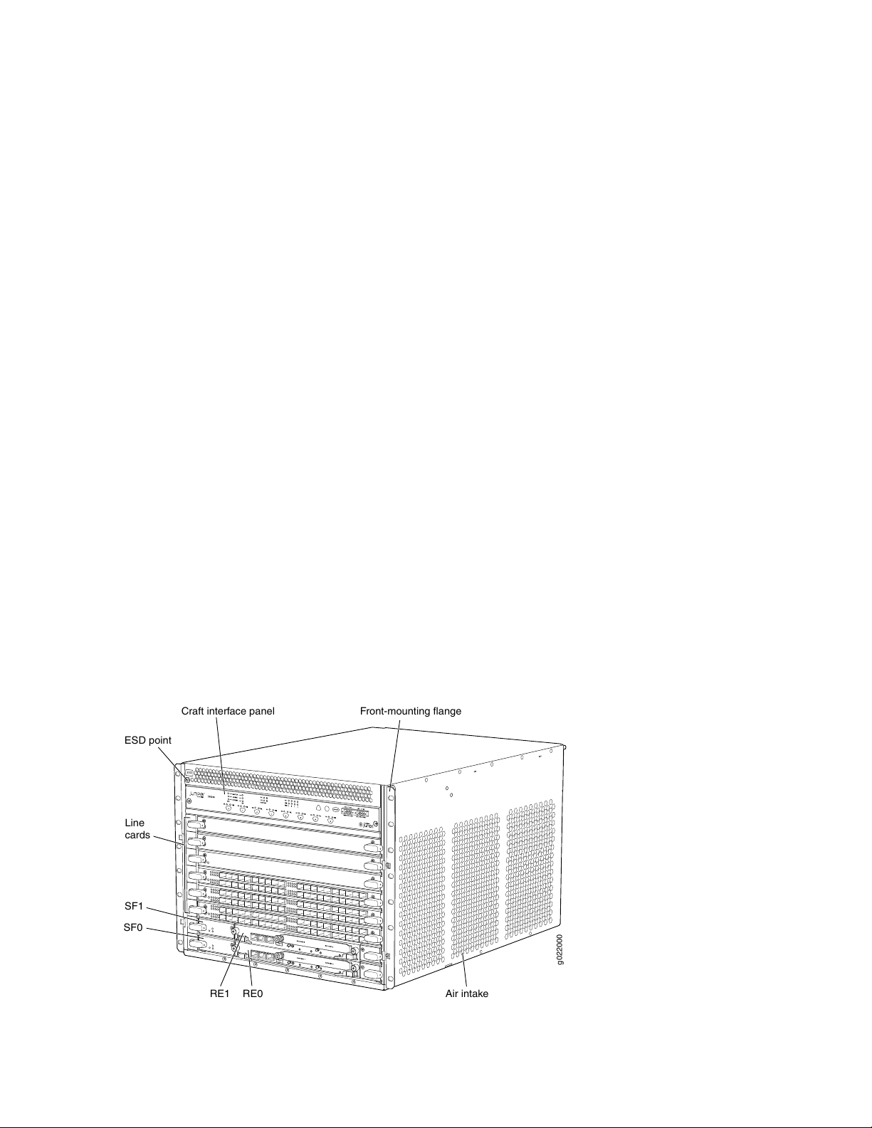
Chassis Physical Specifications
The EX9208 switch is eight rack units (8 U) in size. Five EX9208 switches can fit in a standard 48 U rack.
Each EX9208 switch is designed to optimize rack space and cabling. See Figure 1 on page 23,
Figure 2 on page 24, and Figure 3 on page 24.
Figure 1: Front View of an EX9208 Switch
Page 24
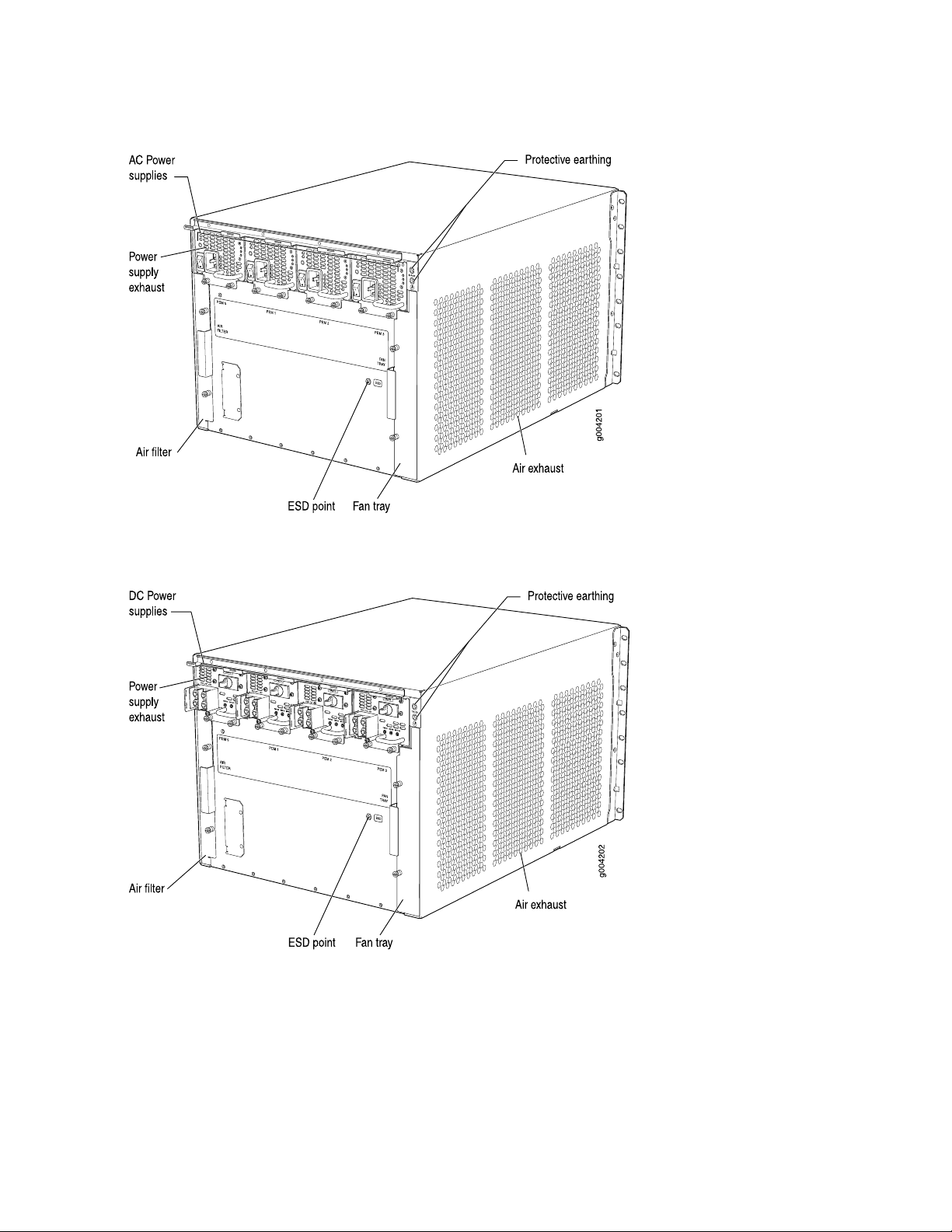
Figure 2: Rear View of an EX9208 Switch with AC Power Supplies
24
Figure 3: Rear View of an EX9208 Switch with DC Power Supplies
Host Subsystem
Switching and routing functionality, system management, and system control functions of an EX9208
switch are performed by the host subsystem. The host subsystem consists of a Routing Engine functioning
together with a Switch Fabric.
Page 25

You can install either one or two host subsystems in the slots labeled 0 and 1 in the front panel of the
chassis. A base-configuration EX9208 switch has one host subsystem. A redundant-configuration EX9208
switch has a second host subsystem. For more information, see “EX9208 Switch Configurations” on page 27.
Line Cards
The EX9208 switch has six horizontal line card slots and supports line rate for each line card. The line cards
in EX9208 switches combine a Packet Forwarding Engine and Ethernet interfaces in a single assembly.
Line cards are field-replaceable units (FRUs) that you can install in the line card slots—labeled 0 through
5—on the front of the switch chassis. All line cards are hot-removable and hot-insertable. Table 3 on page 25
lists the line cards available for EX9208 switches.
Table 3: Line Cards Available for EX9208 Switches
Additional InformationDescriptionModel
25
EX9200-2C-8XS
EX9200-4QS
EX9200-6QS
EX9200-MPC
EX9200-12QS
Ethernet ports and eight 10-Gigabit
Ethernet ports
Ethernet ports
Ethernet ports and 24 10-Gigabit
Ethernet ports
of the following MICs:
EX9200-10XS-MIC
•
EX9200-20F-MIC
•
EX9200-40T-MIC
•
Ethernet rate-selectable ports, each
of which can house transceivers
“EX9200-2C-8XS Line Card” on page 87A line card with two 100-Gigabit
“EX9200-4QS Line Card” on page 89A line card with four 40-Gigabit
“EX9200-6QS Line Card” on page 90A line card with six 40-Gigabit
“EX9200-MPC Line Card” on page 93A modular line card that accepts any
“EX9200-12QS Line Card” on page 96A line card with six 40-Gigabit
EX9200-15C
EX9200-32XS
“EX9200-15C Line Card” on page 99line card with 15 rate-selectable
ports. All ports can operate at
10-Gbps, 25-Gbps, 40-Gbps, or
100-Gbps speeds
“EX9200-32XS Line Card” on page 103A line card with 32 10-Gigabit
Ethernet ports
Page 26
Table 3: Line Cards Available for EX9208 Switches (continued)
26
Additional InformationDescriptionModel
EX9200-40T
EX9200-40F
EX9200-40F-M
EX9200-40XS
Cooling System
“EX9200-40T Line Card” on page 104A line card with 40
10/100/1000BASE-T ports that
support RJ-45 connectors
“EX9200-40F Line Card” on page 106A line card with 40 1-Gigabit
Ethernet ports
“EX9200-40F-M Line Card” on page 107A line card with 40 1-Gigabit
Ethernet ports with Media Access
Control Security (MACsec) capability
“EX9200-40XS Line Card” on page 109A line card with 40 10-Gigabit
Ethernet ports with Media Access
Control Security (MACsec) capability,
each of which can house 10-gigabit
small form-factor pluggable plus
(SFP+) transceivers
The cooling system in an EX9208 switch is a field-replaceable unit (FRU). It consists of a hot-removable
and hot-insertable fan tray. The fan tray contains six fans. The fan tray installs vertically on the right back
of the chassis and provides side-to-side chassis cooling. See “EX9208 Cooling System” on page 51.
Power Supplies
Power supplies for the EX9208 switch are fully redundant, load-sharing, and hot-removable and
hot-insertable FRUs. Each EX9208 switch chassis can hold up to four AC or DC power supplies.
Table 4 on page 26 shows the details of the power supplies available for EX9208 switches.
Table 4: Power Supplies Supported on EX9208 Switches
Output PowerInput VoltagePower Supply
1167 WLow-voltage line (100–120 VAC)2520 W AC
2050 WHigh-voltage line (200–240 VAC)
2400 W to 2600 W–40 VDC through –70 VDC2400 W DC
Page 27
A base-configuration EX9208 switch ships with three low-line (100–120 VAC) or two high-line
(200–240 VAC) AC power supplies. An AC-powered, redundant-configuration EX9208 switch ships with
four low-line (100–120 VAC) or four high-line (200–240 VAC) AC power supplies. See “AC Power Supply
in an EX9208 Switch” on page 53.
A DC-powered, redundant-configuration EX9208 switch ships with four DC power supplies. See “DC
Power Supply in an EX9208 Switch” on page 60.
CAUTION: Do not mix AC and DC power supplies in the same chassis.
EX9208 Switch Configurations
Table 5 on page 27 lists the hardware configurations for an EX9208 switch—base (AC) and redundant (AC
and DC versions)—and the components included in each configuration.
27
Table 5: EX9208 Switch Hardware Configurations
EX9208-BASE3C-AC
(base configurationwith 2520 W AC
power supplies)
EX9208-RED3C-DC
(redundant configuration with
2520 W AC power supplies)
Chassis with craft interface and midplane
•
One EX9200-SF3 module
•
One EX9200-RE2 module
•
One fan tray
•
Three 2520 W AC power supplies
•
Blank panels for the line card slots
•
Blank panel for the empty power supply slot
•
Chassis with craft interface and midplane
•
Two EX9200-SF3 modules
•
Two EX9200-RE2 modules
•
One fan tray
•
Four 2520 W DC power supplies
•
Blank panels for line card slots
•
First Junos OS
ReleaseConfiguration ComponentsSwitch Configuration
20.3R1
20.3R1
Page 28

Table 5: EX9208 Switch Hardware Configurations (continued)
28
First Junos OS
ReleaseConfiguration ComponentsSwitch Configuration
EX9208-RED3C-AC
(redundant configuration with
2520 W AC power supplies)
EX9208-BASE3B-AC
(base configuration with 2520 W AC
power supplies)
EX9208-RED3B-DC
(redundant configuration with
2520 W AC power supplies)
Chassis with craft interface and midplane
•
Two EX9200-SF3 modules
•
Two EX9200-RE2 modules
•
One fan tray
•
Four 2520 W AC power supplies
•
Blank panels for line card slots
•
Chassis with craft interface and midplane
•
One EX9200-SF2 module
•
One EX9200-RE2 module
•
One fan tray
•
Three 2520 W AC power supplies
•
Blank panels for the line card slots
•
Blank panel for the empty power supply slot
•
Chassis with craft interface and midplane
•
Two EX9200-SF2 modules
•
Two EX9200-RE2 modules
•
One fan tray
•
Four 2520 W DC power supplies
•
Blank panels for line card slots
•
20.3R1
17.1R1
17.1R1
EX9208-RED3B-AC
(redundant configuration with
2520 W AC power supplies)
Chassis with craft interface and midplane
•
Two EX9200-SF2 modules
•
Two EX9200-RE2 modules
•
One fan tray
•
Four 2520 W AC power supplies
•
Blank panels for line card slots
•
17.1R1
Page 29

Table 5: EX9208 Switch Hardware Configurations (continued)
29
First Junos OS
ReleaseConfiguration ComponentsSwitch Configuration
EX9208-BASE3A-AC
(base configuration with 2520 W AC
power supplies)
EX9208-REDUND3A-AC
(redundant configuration with
2520 W AC power supplies)
EX9208-REDUND3A-DC
(redundant configuration with
2400 W DC power supplies)
Chassis with craft interface and midplane
•
One EX9200-SF2 module
•
One EX9200-RE module
•
One fan tray
•
One air filter kit
•
Three 2520 W AC power supplies
•
One EX9200-SF module cover panel
•
Six line card cover panels
•
Blank panels for empty power supply slots
•
Chassis with craft interface and midplane
•
Two EX9200-SF2 modules
•
Two EX9200-RE modules
•
One fan tray
•
One air filter kit
•
Four 2520 W AC power supplies
•
Six line card cover panels
•
Chassis with craft interface and midplane
•
Two EX9200-SF2 modules
•
Two EX9200-RE modules
•
One fan tray
•
One air filter kit
•
Four 2400 W DC power supplies
•
Six line card cover panels
•
14.1
14.1
14.1
EX9208-BASE-AC
(base configuration with 2520 W AC
power supplies)
Chassis with craft interface and midplane
•
One EX9200-SF module
•
One EX9200-RE module
•
One fan tray
•
One air filter kit
•
Three 2520 W AC power supplies
•
One EX9200-SF module cover panel
•
Six line card cover panels
•
Blank panels for empty power supply slots
•
12.3R2
Page 30

Table 5: EX9208 Switch Hardware Configurations (continued)
30
First Junos OS
ReleaseConfiguration ComponentsSwitch Configuration
EX9208-REDUND-AC
(redundant configuration with
2520 W AC power supplies)
EX9208-REDUND-DC
(redundant configuration with
2400 W DC power supplies)
Chassis with craft interface and midplane
•
Two EX9200-SF modules
•
Two EX9200-RE modules
•
One fan tray
•
One air filter kit
•
Four 2520 W AC power supplies
•
Six line card cover panels
•
Chassis with craft interface and midplane
•
Two EX9200-SF modules
•
Two EX9200-RE modules
•
One fan tray
•
One air filter kit
•
Four 2400 W DC power supplies
•
Six line card cover panels
•
NOTE: You can install up to six line cards (in any combination) in the switch.
12.3R2
12.3R2
NOTE: Line cards are not part of the base or redundant configuration. You must order them
separately.
NOTE: Power cords and additional power supplies (AC or DC) must be purchased separately.
EX9208 Switch Hardware and CLI Terminology Mapping
This topic describes the hardware terms used in EX9208 switch documentation and the corresponding
terms used in the Junos OS CLI. See Table 6 on page 31.
Page 31

Table 6: CLI Equivalents of Terms Used in Documentation for EX9208 Switches
31
Hardware
Item (CLI)
Midplane
PEM (n)
EX9208-BP
•
EX9208-BP3
•
One of the following:
PS 1.4-2.52 kW;
•
90-264 V AC in
DC 2.4 kW Power
•
Entry Module
n is a value in the range
0-3. The value corresponds
to the power supply slot
number.
Item in
DocumentationValue (CLI)Description (CLI)
Switch chassis–EX9208Chassis
Switch midplane–One of the following:
Craft Interface–Front Panel DisplayFPM Board
AC or DC power
supply
Additional
Information
“Chassis Physical
Specifications of an
EX9208 Switch” on
page 35
Midplane in an
EX9200 Switch
Craft Interface in an
EX9200 Switch
AC Power Supply in
•
an EX9208 Switch
on page 53
DC Power Supply
•
in an EX9208
Switch on page 60
Routing
Engine (n)
One of the following:
RE–S–EX9200
•
–1800X4
RE–S–EX9200
•
–2X00x6
0-1.
In a base configuration,
only one entry appears.
In a redundant
configuration, two entries
appear–one for each
Routing Engine module (RE
module) installed in the
chassis.
RE modulen is a value in the range
“Routing Engine
Module in an EX9200
Switch” on page 67
Page 32

Table 6: CLI Equivalents of Terms Used in Documentation for EX9208 Switches (continued)
32
Hardware
Item (CLI)
CB (n)
FPC (n)
One of the following:
EX9200–SCBE
•
EX9200–SF2
•
EX9200-SF3
•
Abbreviated name of
the line card.
One of the following:
EX9200-2C-8XS
•
EX9200 4x40G
•
QSFP
EX9200
•
24x10GE+6x40GE
EX9200-MPC
•
EX9200-12QS
•
EX9200-15C
•
EX9200 32x10G
•
SFP
EX9200 40x1G
•
Copper
EX9200-40x1G-SFP
•
EX9200-40FE
•
EX9200-40XS
•
0-1.
Multiple line items appear
in the CLI if more than one
Switch Fabric modules (SF
modules) is installed in the
chassis.
CB0 and CB1 stand for SF
modules.
n is a value in the range
0-5. The value corresponds
to the line card slot number
in which the line card is
installed.
Item in
DocumentationValue (CLI)Description (CLI)
SF modulen is a value in the range
Line card (The switch
does not have actual
FPCs—the line cards
are the FPC
equivalents on the
switch.)
Additional
Information
“Switch Fabric
Module in an EX9200
Switch” on page 73
EX9200-2C-8XS
•
Line Card on
page 87
EX9200-4QS Line
•
Card on page 89
EX9200-6QS Line
•
Card on page 90
EX9200-MPC Line
•
Card on page 93
EX9200-12QS Line
•
Card on page 96
EX9200-15C Line
•
Card on page 99
EX9200-32XS Line
•
Card on page 103
EX9200-40T Line
•
Card on page 104
EX9200-40F Line
•
Card on page 106
EX9200-40F-M
•
Line Card on
page 107
EX9200-40XS Line
•
Card on page 109
Page 33

Table 6: CLI Equivalents of Terms Used in Documentation for EX9208 Switches (continued)
33
Hardware
Item (CLI)
MIC (n)
Abbreviated name of
the Modular Interface
Card (MIC).
One of the following
if EX9200-MPC line
card is installed:
10X10GE SFPP
•
20X1GE SFP
•
MACSEC
40x1GE RJ45
•
n is a value in the range
0-1.
Item in
DocumentationValue (CLI)Description (CLI)
Line card
NOTE:
The switch does not
have actual MICs
except in the
EX9200-MPC line
card—the line cards
are the MIC
equivalents on the
switch. EX9200-MPC
is a modular line card
that accepts any of
the following MICs:
EX9200-10XS-MIC
•
EX9200-20F-MIC
•
EX9200-40T-MIC
•
Additional
Information
EX9200-2C-8XS
•
Line Card on
page 87
EX9200-4QS Line
•
Card on page 89
EX9200-6QS Line
•
Card on page 90
EX9200-MPC Line
•
Card on page 93
EX9200-12QS Line
•
Card on page 96
EX9200-15C Line
•
Card on page 99
EX9200-32XS Line
•
Card on page 103
EX9200-40T Line
•
Card on page 104
EX9200-40F Line
•
Card on page 106
EX9200-40F-M
•
Line Card on
page 107
EX9200-40XS Line
•
Card on page 109
Page 34

Table 6: CLI Equivalents of Terms Used in Documentation for EX9208 Switches (continued)
34
Hardware
Item (CLI)
PIC (n)
Abbreviated name of
the Physical Interface
Card (PIC).
n is a value in the range
0-3.
Item in
DocumentationValue (CLI)Description (CLI)
Line card (The switch
does not have actual
PICs.)
Additional
Information
EX9200-2C-8XS
•
Line Card on
page 87
EX9200-4QS Line
•
Card on page 89
EX9200-6QS Line
•
Card on page 90
EX9200-MPC Line
•
Card on page 93
EX9200-12QS Line
•
Card on page 96
EX9200-15C Line
•
Card on page 99
EX9200-32XS Line
•
Card on page 103
EX9200-40T Line
•
Card on page 104
EX9200-40F Line
•
Card on page 106
EX9200-40F-M
•
Line Card on
page 107
EX9200-40XS Line
•
Card on page 109
Xcvr (n)
Fan tray
Abbreviated name of
the transceiver.
Tray
the number of the port in
which the transceiver is
installed.
Optical transceiversn is a value equivalent to
Fan tray–Enhanced Left Fan
“Pluggable
Transceivers
Supported on EX9200
Switches” on page 135
“EX9208 Cooling
System” on page 51
Page 35

Chassis Physical Specifications of an EX9208 Switch
The EX9208 switch chassis is a rigid sheet-metal structure that houses the other switch components.
Table 7 on page 35 summarizes the physical specifications of the EX9208 switch chassis. See
Figure 4 on page 37, Figure 5 on page 37, and Figure 6 on page 38.
Table 7: Physical Specifications of the EX9208 Switch Chassis
DepthWidthHeightWeightDescription
35
Chassis
module (RE
module)
Switch Fabric
module (SF
module)
midplane, craft
interface (front-panel
display), fan tray,
aChassis Physical
Specifications of an
EX9208 Switchir
filter, and cable
management
brackets: 65.5 lb
(29.7 kg)
Maximum
configuration:
163.6 lb (74.2 kg)
Routing Engine
installed)
17.5 in. (44.5 cm)14.0 in. (35.6 cm)Chassis with
24.5 in. (62.2 cm)
(from front to chassis
rear) Total depth
(including cable
management brackets)
27.75 in. (70.5 cm)
7.75 in. (19.7 cm)11 in. (27.9 cm)1.25 in. (3.2 cm)2.4 lb (1.9 kg)Routing Engine
22 in. (55.9 cm)17 in. (43.2 cm)1.25 in. (3.2 cm)9.6 lb (4.4 kg) (with
Switch Fabric
module
Management
Brackets
21.2 in. (53.85 cm)15.7 in. (39.87 cm)1.2 in. (3.05 cm)13.6 lb (6.2 kg)EX9200-SF3
23.3 in. (59.2 cm)1.76 in. (4.5 cm)11.58 in. (29.4 cm)6.8 lb (3.84 kg)Fan Tray
22.23 in. (56.5 cm)0.31 in. (0.8 cm)10.1 in. (25.7 cm)1.0 lb (0.5 kg)Air filter
4.5 in. (11.4 cm)0.25 in. (0.6 cm)9.9 in. (25.1 cm)0.3 lb (0.8 kg)Cable
Page 36

Table 7: Physical Specifications of the EX9208 Switch Chassis (continued)
line card
card
card
card
36
DepthWidthHeightWeightDescription
4 in. (10.2 cm)14.5 in. (36.8 cm)1.75 in. (4.4 cm)6.6 lb (2.99 kg)AC power supply
4 in. (10.2 cm)14.5 in. (36.8 cm)1.75 in. (4.4 cm)6.2 lb (2.81 kg)DC power supply
22 in. (55.9 cm)17 in. (43.2 cm)1.25 in. (3.2 cm)19.4 lb (8.8 kg)EX9200-2C-8XS
22 in. (55.9 cm)17 in. (43.2 cm)1.25 in. (3.2 cm)16.8 lb (7.6 kg)EX9200-4QS line
22 in. (55.9 cm)17 in. (43.2 cm)1.25 in. (3.2 cm)21 lb (9.25 kg)EX9200-6QS line
22 in. (55.9 cm)17 in. (43.2 cm)1.25 in. (3.2 cm)15.96 lb (7.3 kg)EX9200-MPC line
card
card
card
card
card
7.86 in. (20 cm)6.67 in. (16.9 cm)1.25 in. (3.2 cm)1.54 lb (0.7 kg)EX9200-10XS-MIC
7.86 in. (20 cm)6.67 in. (16.9 cm)1.25 in. (3.2 cm)1.2 lb (0.54 kg)EX9200-20F-MIC
22 in. (55.9 cm)13.36 in. (33.9 cm)1.25 in. (3.2 cm)1.9 lb (0.9 kg)EX9200-40T-MIC
22 in. (55.9 cm)17 in. (43.2 cm)1.25 in. (3.2 cm15.7 lb (7.12 kg)EX9200-12QS line
21.2 in. (53.85 cm)15.7 in. (39.87 cm)1.2 in. (3.05 cm)20.4 lb (9.25 kg)EX9200-15C line
22 in. (55.9 cm)17 in. (43.2 cm)1.25 in. (3.2 cm)19.2 lb (8.7 kg)EX9200-32XS line
22 in. (55.9 cm)17 in. (43.2 cm)1.25 in. (3.2 cm)14.0 lb (6.6 kg)EX9200-40T line
22 in. (55.9 cm)17 in. (43.2 cm)1.25 in. (3.2 cm)14.8 lb (6.7 kg)EX9200-40F line
line card
22 in. (55.9 cm)17 in. (43.2 cm)1.25 in. (3.2 cm)14.8 lb (6.7 kg)EX9200-40F-M
Page 37

Table 7: Physical Specifications of the EX9208 Switch Chassis (continued)
ESD
g022000
Front-mounting flange
SF1
RE1 RE0
Line
cards
SF0
ESD point
Craft interface panel
Air intake
card
Figure 4: EX9208 Switch
37
DepthWidthHeightWeightDescription
22 in. (55.9 cm)17 in. (43.2 cm)1.25 in. (3.2 cm)17 lb (7.7 kg)EX9200-40XS line
Figure 5: EX9208 Switch with AC Power Supplies
Page 38

Figure 6: EX9208 Switch with DC Power Supplies
38
You can mount an EX9208 switch on a standard 19-in. four-post rack or a standard 800-mm enclosed
cabinet. You can mount up to six EX9208 switches in a standard (48 rack unit (U)) rack.
SEE ALSO
Installing and Removing EX9208 Switch Hardware Components
Field-Replaceable Units in an EX9200 Switch
Field-replaceable units (FRUs) are switch components that you can replace at your site. The EX9200 switch
uses the following types of FRUs:
Hot-insertable and hot-removable—You can remove and replace these components without powering
•
off the switch or disrupting the switching function.
Hot-pluggable—You can remove and replace these components without powering off the switch, but
•
the switching function is interrupted until you replace the component.
Table 8 on page 39 lists the FRUs for the EX9200 switch and their types.
Page 39

Table 8: FRUs in an EX9200 Switch
39
TypeFRU
Hot-insertable and hot-removable.Power supplies
Hot-insertable and hot-removable.Fan tray and air filter
Routing Engine module (RE module)
Switch Fabric module (SF module)
Redundant configuration:
Primary RE module is hot-pluggable.
•
Backup RE module is hot-insertable and hot-removable.
•
Base configuration:
You must disable the switch before removing any RE module.
•
See “Taking the Host Subsystem Offline in an EX9200 Switch”
on page 212.
See EX9204 Switch Configurations, “EX9208 Switch
Configurations” on page 27, and EX9214 Switch Configurations.
Redundant configuration:
Primary SF module is hot-pluggable.
•
Backup SF module is hot-insertable and hot-removable.
•
Base configuration:
You must disable the switch before removing any SF module.
•
See “Taking the Host Subsystem Offline in an EX9200 Switch”
on page 212.
Line cards
See “Pluggable Transceivers Supported on
EX9200 Switches” on page 135 for the Junos OS
release in which the transceivers were
introduced.
See EX9204 Switch Configurations, “EX9208 Switch
Configurations” on page 27, and EX9214 Switch Configurations.
Hot-insertable and hot-removable. We recommend that you take
the line cards offline before removing them. See “Removing a
Line Card from an EX9200 Switch” on page 241.
Hot-insertable and hot-removable.SFP, SFP+, QSFP+, and CFP transceivers
Page 40

NOTE: Line cards are not part of the base or redundant configuration. You must order them
separately.
NOTE: If you have a Juniper J-Care service contract, register any addition, change, or upgrade
of hardware components at
https://www.juniper.net/customers/support/tools/updateinstallbase/ . Failure to do so can
result in significant delays if you need replacement parts. This note does not apply if you replace
existing components with the same type of component.
EX9208 Chassis
40
IN THIS SECTION
Understanding EX9208 Switch Component and Functionality Redundancy | 40
Craft Interface in an EX9200 Switch | 42
Midplane in an EX9200 Switch | 48
Cable Management Brackets in an EX9208 Switch | 50
Understanding EX9208 Switch Component and Functionality Redundancy
The Juniper Networks EX9208 Ethernet Switches are available as fully redundant system. A redundant
EX9208 switch configuration is designed so that no single point of failure can cause the entire switch to
fail. See “EX9208 Switch Configurations” on page 27.
The following hardware components provide redundancy to an EX9208 switch:
Host Subsystem—The host subsystem consists of a Routing Engine functioning together with a Switch
•
Fabric. The host subsystem performs switching and routing functionality, system management, and
system control functions of the switch. The switch can have one or two host subsystems. If two host
subsystems are installed, one functions as the primary and the other functions as the backup. If the
primary host subsystem (or either of its components) fails, the backup can take over as the primary. To
Page 41

operate, each host subsystem requires a Routing Engine module (RE module) installed directly into in a
Switch Fabric module (SF module).
If the Routing Engines are configured for graceful switchover, the backup Routing Engine automatically
synchronizes its configuration and state with the primary Routing Engine. Any update to the primary
Routing Engine state is replicated on the backup Routing Engine. If the backup Routing Engine assumes
primary role, packet forwarding continues through the switch without interruption. See “Host Subsystem
in an EX9200 Switch” on page 66.
Power supplies—In the low-line (100 V) AC power configuration, the switch contains three or four AC
•
power supplies, located horizontally at the rear of the chassis in slots PEM0 through PEM3 (left to right).
Each AC power supply provides power to all components in the switch. When three power supplies are
present, they share power almost equally within a fully populated system. Four AC power supplies
provide full power redundancy. If one power supply fails or is removed, the remaining power supplies
instantly assume the entire electrical load without interruption. Three power supplies provide the
maximum configuration with full power for as long as the switch is operational.
In the high-line (200 V) AC power configuration, the switch contains two or four AC power supplies
located horizontally at the rear of the chassis in slots PEM0 through PEM3 (left to right). Each AC power
supply provides power to all components in the switch. When two or more power supplies are present,
they share power almost equally within a fully populated system. Four AC power supplies provide full
power redundancy. If one power supply fails or is removed, the remaining power supplies instantly
assume the entire electrical load without interruption. Two power supplies provide the maximum
configuration with full power for as long as the switch is operational.
41
In the DC configuration, two power supplies are required to supply power to a fully configured switch.
One power supply supports approximately half of the components in the switch, and the other power
supply supports the remaining components. The addition of two power supplies provides full power
redundancy. If one power supply fails or is removed, the remaining power supplies instantly assume the
entire electrical load without interruption. Two power supplies provide the maximum configuration with
full power for as long as the switch is operational.
See “AC Power Supply in an EX9208 Switch” on page 53 and “DC Power Supply in an EX9208 Switch”
on page 60.
Cooling system—The cooling system in EX9208 switches consists of fan tray and air filter. The fan tray
•
contains six fans. Under normal operating conditions, the fans in the fan tray run at less than full speed.
If one of the fans fails, the host subsystem increases the speed of the remaining fans to provide sufficient
cooling for the switch indefinitely. See “EX9208 Cooling System” on page 51.
Page 42

Craft Interface in an EX9200 Switch
g022028
3
1
5
4
8
7
6
2
IN THIS SECTION
Host Subsystem LEDs | 44
Fan LEDs | 44
Power Supply (PEM) LEDs | 45
Switch Fabric LEDs and Control Buttons | 45
Line Card LEDs and Control Buttons | 46
Alarm LEDs and Alarm Cutoff Button | 46
Alarm Relay Contacts | 47
42
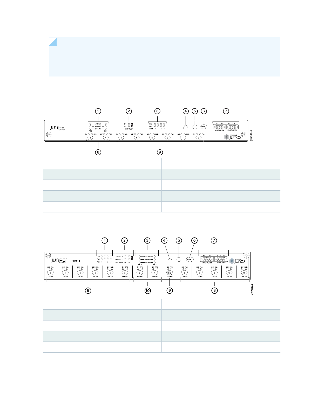
The craft interface enables you to view status and troubleshooting information at a glance and to perform
many system control functions. The craft interface is located on the front panel of the switch. It contains
LEDs and on and off buttons for switch components, the alarm relay contacts, and an alarm cutoff button.
Figure 7 on page 42 shows the craft interface in an EX9204 switch. Figure 8 on page 43 shows the craft
interface in an EX9208 switch. Figure 9 on page 43 shows the craft interface in an EX9214 switch.
Figure 7: Craft Interface in an EX9204 Switch
5—1— Major alarm LEDHost subsystem LEDs
6—2— Alarm cutoff/lamp test buttonFan LEDs
7—3— Alarm relay contactsPower supply LEDs
Minor alarm LED
8—4— LEDs and control buttons for Switch Fabric and Line
cards
Page 43
NOTE: You can install a line card or an SF module in the multifunctional slot labeled 1|0 in
g022004
1 2 3 4 5 6 7
8 9
EX9204 switches. The corresponding LED displays information depending on the hardware
installed in that slot.
Figure 8: Craft Interface in an EX9208 Switch
6—1— Alarm cutoff/lamp test buttonHost subsystem LEDs
43
5—Major alarm LED
Figure 9: Craft Interface in an EX9214 Switch
7—2— Alarm relay contactsFan LEDs
8—3— Switch Fabric LEDs and control buttonsPower supply LEDs
9—4— Line card LEDs and control buttonsMinor alarm LED
6—1— Alarm cutoff/lamp test buttonPower supply LEDs
7—2— Alarm relay contactsFan LEDs
8—3— Line card LEDs and control buttonsHost subsystem LEDs
9—4— Switch Fabric/line card LED and control buttonMinor alarm LED
10—5— Switch Fabric LEDs and control buttonsMajor alarm LED
Page 44

NOTE: You can install a line card or a Switch Fabric module (SF module) in slot nine—labeled 2
| 6. The corresponding LED displays information depending on the hardware installed in that
slot.
NOTE: At least one Switch Fabric module (SF module) with a Routing Engine module (RE module)
must be installed in the switch for the craft interface to obtain power.
The craft interface has the following components:
Host Subsystem LEDs
Each host subsystem (RE module with SF module) has three LEDs, located on the upper left of the craft
interface, to indicate its status. The LEDs grouped with labels RE0 and RE1 show the status of the host
subsystems installed in the switch. Table 9 on page 44 describes the functions of these LEDs.
44
Table 9: Host Subsystem LEDs on the Craft Interface
DescriptionStatusLabel
Host subsystem is functioning as the primary.GreenMASTER
Unlit
Host subsystem is either functioning as the backup or
not installed.
Host subsystem is online and is functioning normally.GreenONLINE
Host subsystem is either offline or not installed.Unlit
Host subsystem is installed but Routing Engine is offline.RedOFFLINE
Host subsystem is not installed.Unlit
Fan LEDs
The fan LEDs are located on the top left of the craft interface. Table 10 on page 45 describes the functions
of the fan LEDs.
Page 45

Table 10: Fan LEDs on the Craft Interface
DescriptionStatusLabel
Fan is functioning normally.GreenOK
Fan is not installed.Unlit
Fan has failed.RedFAIL
Fan is not installed or functioning normally.Unlit
Power Supply (PEM) LEDs
Each power supply has two LEDs on the craft interface that indicate its status. The LEDs—labeled 0 through
3—are located on the craft interface next to the PEM label. Table 11 on page 45 describes the functions
of the power supply LEDs on the craft interface.
45
Table 11: Power Supply LEDs on the Craft Interface
DescriptionStatusLabel
Power supply is functioning normally.GreenOK
Power supply in not installed.Off
Power supply has failed.RedFAIL
Power supply is not installed or functioning normally.Off
Switch Fabric LEDs and Control Buttons
Each Switch Fabric module has two LEDs on the craft interface that indicates its status. The LEDs—OK
and FAIL—are associated with control buttons and are located along the bottom of the craft interface.
You can turn the SF modules on or off by pressing these buttons on the craft interface.
Table 12 on page 46 describes the status of the SF module LEDs.
Page 46

Table 12: Switch Fabric Module LEDs on the Craft Interface
46
DescriptionStatusLabel
GreenOK
Unlit
On steadily—The SF module is functioning
normally.
Blinking—The SF module is coming online or
going offline.
The SF module is not online.Unlit
The SF module has failed.RedFAIL
The SF module is not installed or is not functioning
normally.
Line Card LEDs and Control Buttons
Each line card has two LEDs—OK and FAIL—on the craft interface that indicates its status. The line card
LEDs are associated with control buttons and are located along the bottom of the craft interface. You can
turn a line card online or offline by using its control button on the craft interface. Table 13 on page 46
describes the function of the line card LEDs.
Table 13: Line Card LEDs on the Craft Interface
DescriptionStatusLabel
On steadily—Line card is functioning normally.GreenOK
Blinking—Line card is coming online or going offline.
Line card is not online.Unlit
Line card has failed.RedFAIL
Line card is not installed or functioning normally.Unlit
Alarm LEDs and Alarm Cutoff Button
Two large alarm LEDs are located at the upper right of the craft interface. The circular LED called major
alarm LED glows to indicate a critical condition that can result in a system shutdown. The triangular LED
called minor alarm LED glows to indicate a less severe condition (warning) that requires monitoring or
maintenance. Both LEDs can be lit simultaneously.
Page 47

A condition that causes an LED to be lit also activates the corresponding alarm relay contact on the craft
g022029
Craft Interface panel
Alarm
relay
contacts
interface.
The alarm cutoff/lamp test (ACO/LT) button, located next to the alarm LEDs, is a control button for alarms.
You can press the ACO/LT button to deactivate major and minor alarms. Deactivating an alarm turns off
both LEDs and deactivates the device attached to the corresponding alarm relay contact on the craft
interface.
Table 14 on page 47 describes the alarm LEDs and the alarm cutoff/lamp test button.
Table 14: Alarm LEDs and Alarm Cutoff/Lamp Test Button
DescriptionStatusAlarm LEDs and Button
47
Red
Major alarm LED
Yellow
Minor alarm LED
–
Alarm cutoff/lamp test button
Indicates a critical condition that can cause the switch to stop
functioning. Possible causes include component removal, failure,
or overheating.
Indicates a serious but nonfatal error condition, such as warning
for a maintenance or a significant increase in component
temperature.
Deactivates major and minor alarms. Causes all LEDs on the
craft interface to light (for testing) when pressed and held.
Alarm Relay Contacts
The craft interface has two alarm relay contacts for connecting the switch to external alarm devices.
Whenever a system condition triggers either the critical (major alarm) or warning (minor alarm) alarm on
the craft interface, the alarm relay contacts are also activated. The alarm relay contacts are located on the
upper right of the craft interface.
Figure 10 on page 47 shows the alarm relay contacts in EX9200 switches.
Figure 10: Alarm Relay Contacts in EX9200 Switches
Page 48
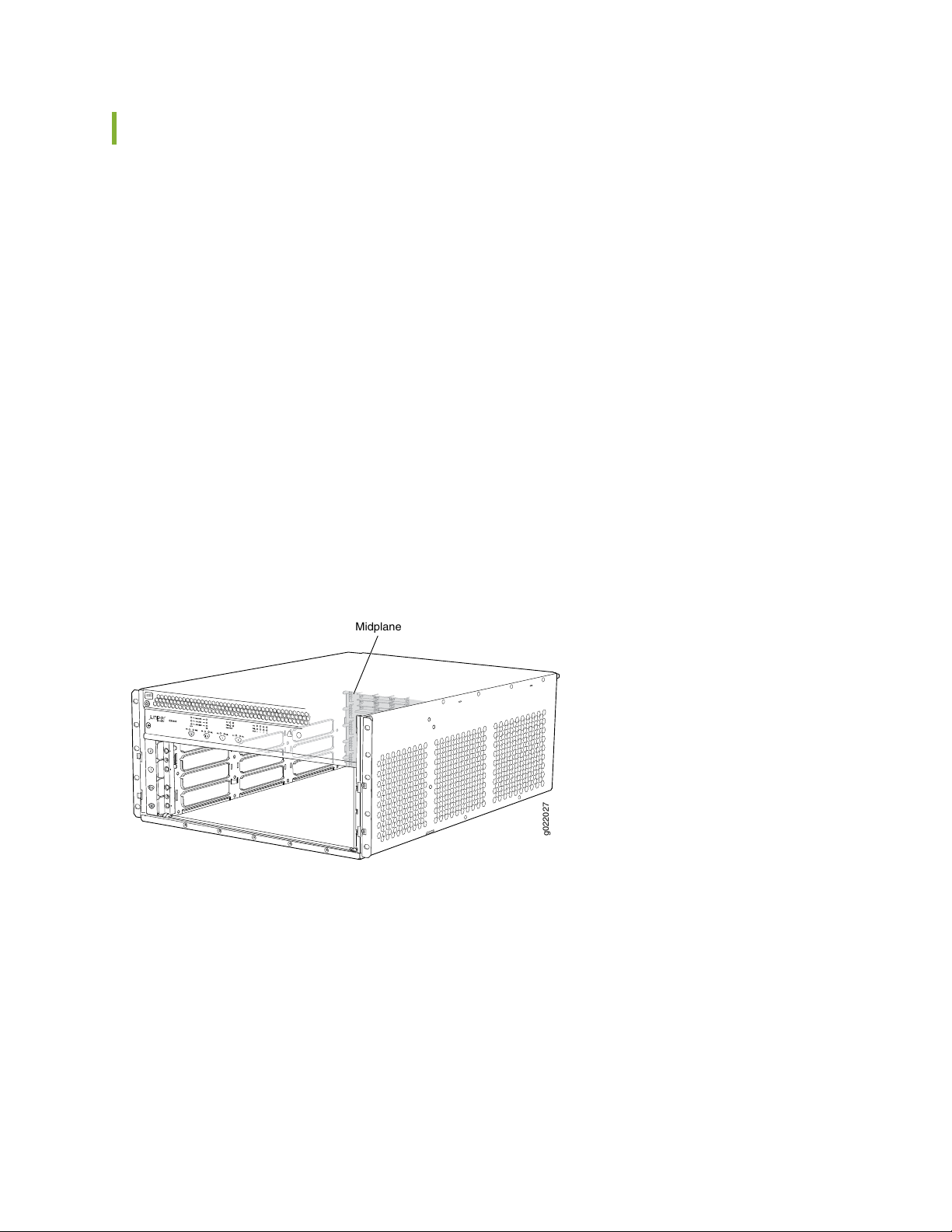
Midplane in an EX9200 Switch
ESD
g022027
Midplane
The midplane is located on the rear of the chassis and forms the rear of the card cage. The Switch Fabric
modules (SF modules) and line cards are installed into the midplane from the front of the chassis, and the
power supplies install into the midplane from the rear of the chassis. The cooling system components also
connect to the midplane.
The midplane performs the following major functions:
Provides a data path—Data packets are transferred across the midplane between the line cards through
•
the Switch Fabric on the host subsystem.
Distributes power—The power supplies connect to the midplane, which distributes power to all the
•
switch components.
Provides a signal path—The midplane provides the signal path to the line cards, Switch Fabric, and other
•
system components for monitoring and control of the system.
Figure 11 on page 48 shows the midplane in an EX9204 switch. Figure 12 on page 49 shows the midplane
in an EX9208 switch. Figure 13 on page 49 shows the midplane in an EX9214 switch.
48
Figure 11: Midplane in an EX9204 Switch
Page 49

Figure 12: Midplane in an EX9208 Switch
g022001
Midplane
g022043
Midplane
49
Figure 13: Midplane in an EX9214 Switch
Page 50
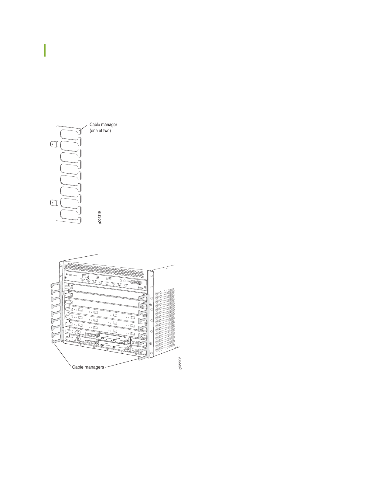
Cable Management Brackets in an EX9208 Switch
g022005
Cable managers
The cable management brackets (see Figure 14 on page 50) consist of plastic dividers located on the left
and right sides of each line card slot and Switch Fabric module (SF module) slot. The cable management
brackets allow you to route the cables outside the switch and away from the line cards and SF modules.
Figure 14: Cable Management Brackets
50
Figure 15: Cable Management Brackets Installed on the Switch
Page 51

EX9208 Cooling System
IN THIS SECTION
Fan Tray | 51
Airflow Direction in the EX9208 Switch Chassis | 52
The cooling system in an EX9208 switch consists of a fan tray and an air filter. The cooling system
components work together to keep all switch components within the acceptable temperature range.
51
Fan Tray
Fan tray is a hot-insertable and hot-removable field-replaceable unit (FRU) and contains six fans. The fan
tray and air filter install vertically in the rear of the switch. See Figure 16 on page 51 and
Figure 17 on page 52.
Figure 16: Fan Tray for an EX9208 Switch
Page 52
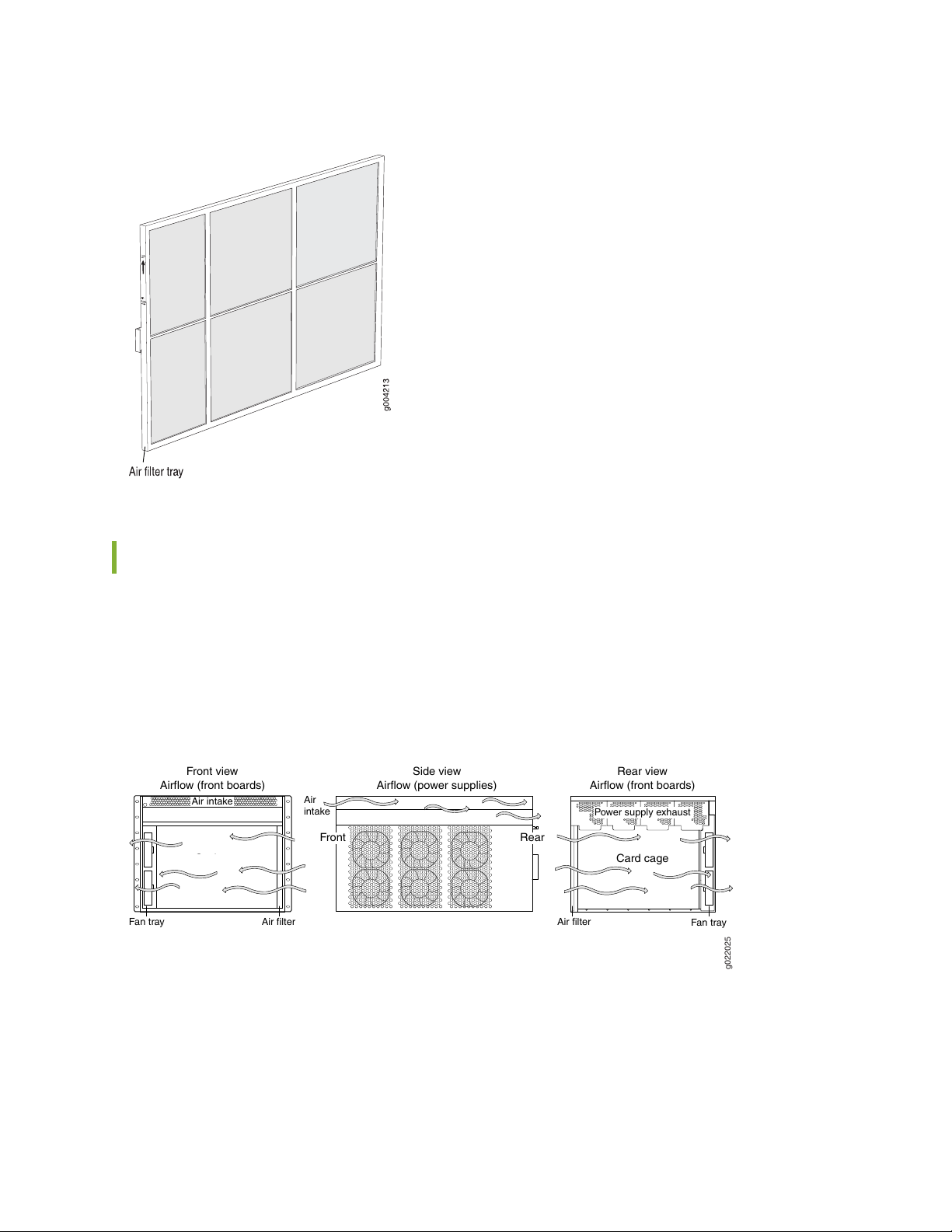
Figure 17: Air Filter for an EX9208 Switch
Fan tray
Card cage
g022025
Front view
Airflow (front boards)
Side view
Airflow (power supplies)
Front
Air filter Air filter
Air
intake
Air intake
Power supply exhaust
Fan tray
Rear
Card cage
Rear view
Airflow (front boards)
52
Airflow Direction in the EX9208 Switch Chassis
The air intake to cool the chassis is located on the side of the chassis next to the air filter. Air is pulled
through the chassis toward the fan tray, where it is exhausted out through the side of the chassis. The air
intake to cool the power supplies is located in the front of the chassis above the craft interface. See
Figure 18 on page 52.
Figure 18: Airflow Through the EX9208 Switch Chassis
The host subsystem monitors the temperature of switch components. Under normal operating conditions,
the fans in the fan tray run at less than full speed. If a fan fails or the ambient temperature rises above a
threshold, the speed of the remaining fans is automatically adjusted to keep the temperature within the
acceptable range. If the ambient maximum temperature specification is exceeded and the system cannot
Page 53

be adequately cooled, the Routing Engine shuts down the system by disabling output power from each
power supply.
You cannot replace a single fan. If one or more fans fail, you must replace the entire fan tray.
RELATED DOCUMENTATION
Clearance Requirements for Airflow and Hardware Maintenance for an EX9208 Switch | 127
EX9208 Power System
IN THIS SECTION
53
AC Power Supply in an EX9208 Switch | 53
AC Power Supply Specifications for EX9208 Switches | 56
AC Power Cord Specifications for an EX9208 Switch | 57
AC Power Supply LEDs in an EX9208 Switch | 59
DC Power Supply in an EX9208 Switch | 60
DC Power Supply Specifications for EX9208 Switches | 62
DC Power Supply LEDs in an EX9208 Switch | 63
Power Requirements for EX9200 Switch Components | 64
AC Power Supply in an EX9208 Switch
IN THIS SECTION
AC Power Supply Description | 54
AC Power Supply Configurations | 55
Page 54

An EX9208 switch is configurable with two, three, or four AC power supplies. The power supplies connect
to the midplane, which distributes the different output voltages produced by the power supplies to the
switch components, depending on their voltage requirements. Each power supply is cooled by its own
internal cooling system.
CAUTION: EX9208 switches use either AC or DC power supplies. Do not mix AC and
DC power supplies in a switch. The first type of power supply detected by the switch
when initially powered on determines the type of power supply allowed by the switch.
All installed power supplies of the other type are disabled by the switch. If you install
a power supply of the other type while the switch is operating, the switch disables the
power supply and generates an alarm.
This topic describes the AC power supplies in EX9208 switches.
AC Power Supply Description
54
The AC power supplies in EX9208 switches are hot-insertable and hot-removable field-replaceable units
(FRUs).
You can install up to four AC power supplies in an EX9208 switch. Power supplies are installed in the rear
of the chassis in slots PEM0 through PEM3 (left to right).
WARNING: The switch is installed in a restricted-access location. It has a separate
protective earthing terminal (sized for UNC 1/4-20 ground lugs) provided on the chassis
in addition to the grounding pin of the power supply cord. This separate protective
earthing terminal must be permanently connected to earth.
CAUTION: Before switch installation begins, ensure that a licensed electrician has
attached an appropriate grounding lug to the grounding cable that you supply. Using
a grounding cable with an incorrectly attached lug can damage the switch.
Each AC power supply weighs approximately 6.6 lb (2.99 kg) and consists of one AC appliance inlet, an
AC input switch, a fan, and LEDs to monitor the status of the power supply. See Figure 19 on page 55.
Page 55
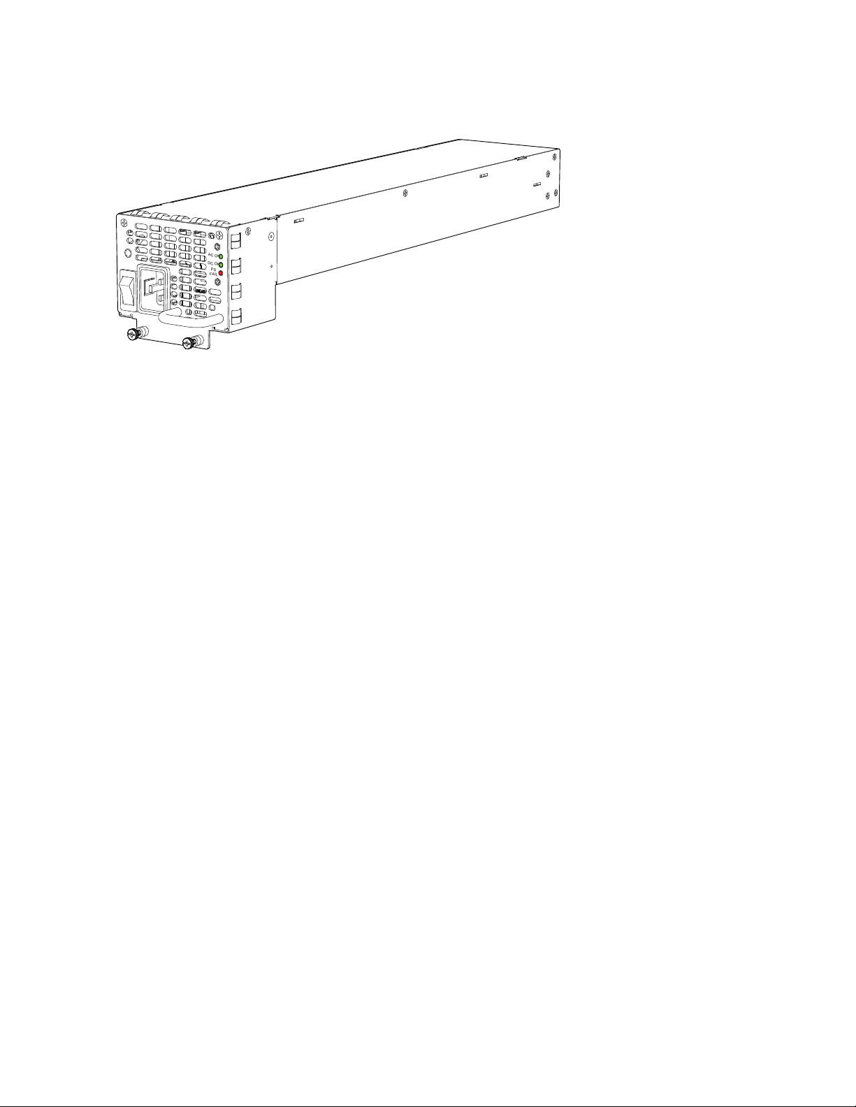
Figure 19: AC Power Supply for an EX9208 Switch
AC OK
DC OK
PS
FAIL
Each power supply has its own fan and is cooled by its own internal cooling system.
EX9208 switches support 2520 W AC power supply. The AC power supply supports both the low-voltage
line (100–120 VAC) and the high-voltage line (200–240 VAC) AC power configurations.
55
Each AC power supply has a single AC appliance inlet located on the power supply that requires a dedicated
AC power feed. We recommend that you use a customer site circuit breaker rated for 16.0 A @ 100 VAC
or 16.0 A @ 200 VAC circuit breaker minimum for each AC power supply, or as required by local code.
Doing so enables you to operate the switch in any configuration without upgrading the power infrastructure.
AC Power Supply Configurations
The EX9208 switch supports either the low-line (100–120 V) AC power configuration or the high-line
(200–240 V) AC power configuration.
In the low-line (100–120 V) AC power configuration, the EX9208 switch contains three or four AC power
•
supplies, located horizontally at the rear of the chassis in slots PEM0 through PEM3 (left to right). Each
AC power supply provides power to all components in the switch. When three power supplies are
present, they share power almost equally within a fully populated system. Four AC power supplies
provide full power redundancy. If one power supply fails or is removed, the remaining power supplies
assume the entire electrical load without interruption. Three power supplies provide the maximum
configuration with full power for as long as the switch is operational. The low-line configuration requires
three power supplies and the fourth power supply provides redundancy.
In the high-line (200–240 V) AC power configuration, the EX9208 switch contains two or four AC power
•
supplies, located horizontally at the rear of the chassis in slots PEM0 through PEM3 (left to right). In a
high-line AC power configuration, each AC power supply provides power to all components in the switch.
When two or more power supplies are present, they share power almost equally within a fully populated
system. Four AC power supplies provide full power redundancy. If one power supply fails or is removed,
the remaining power supplies assume the entire electrical load without interruption. Two power supplies
provide the maximum configuration with full power for as long as the switch is operational. In the
Page 56

two-PEM high-line configuration, slots PEM0 and PEM1 or PEM2 and PEM3 are used. The high-line
configuration requires two power supplies, with the third and fourth providing redundancy.
SEE ALSO
Installing an AC Power Supply in an EX9208 Switch | 205
AC Power Supply Specifications for EX9208 Switches
Table 15 on page 56 lists the power supply specifications for an AC power supply used in EX9208 switches.
Table 15: AC Power Supply Specifications for an EX9208 Switch
SpecificationsItem
56
AC input voltage
AC input current rating
AC output power
Operating range:
Low-voltage line: 100–120 VAC
•
High-voltage line: 200–240 VAC
•
50–60 HzAC input line frequency
Low-voltage line: 16 A
•
High-voltage line: 15.1 A
•
Low-voltage line: 1167 W
•
High-voltage line: 2050 W
•
Table 16 on page 56 lists the AC power system specification for an EX9208 switch.
Table 16: AC Power System Specifications
High-LineLow-LineItem
2+23+1Redundancy
2050 W1167 WOutput power (maximum) per power supply
4100 W3501 WOutput power (maximum) per system
Page 57

AC Power Cord Specifications for an EX9208 Switch
Each AC power supply has a single AC appliance inlet located on the power supply that requires a dedicated
AC power feed. Most sites distribute power through a main conduit that leads to frame-mounted power
distribution panels, one of which can be located at the top of the rack that houses the switch. An AC power
cord connects each power supply to the power distribution panel.
You can order detachable AC power cords, each approximately 8 ft (2.44 m) long that supply AC power
to the switch. The C19 appliance coupler end of the cord inserts into the AC appliance inlet coupler, type
C20 (right angle) as described by International Electrotechnical Commission (IEC) standard 60320. The
plug end of the power cord fits into the power source receptacle that is standard for your geographical
location.
Table 17 on page 57 provides specifications and Figure 20 on page 58 depicts the plug on the AC power
cord provided for each country or region.
Table 17: AC Power Cord Specifications for an EX9208 Switch
57
Switzerland, and United
Kingdom)
Plug TypeElectrical SpecificationModel NumberCountry
SAA/3/15240 VAC, 50 Hz ACCBL-M-PWR-RA-AUAustralia
CH2-16P220 VAC, 50 Hz ACCBL-M-PWR-RA-CHChina
CBL-M-PWR-RA-EUEurope (except Denmark, Italy,
AC
CEE 7/7220 or 230 VAC, 50 Hz
CEI 23-16/VII230 VAC, 50 Hz ACCBL-M-PWR-RA-ITItaly
JIS 8303125 VAC, 50 or 60 Hz ACCBL-PWR-RA-JP15Japan
NEMA L6-20P220 VAC, 50 or 60 Hz ACCBL-M-PWR-RA-JP
NEMA 5-15P125 VAC, 60 Hz ACCBL-PWR-RA-US15North America
NEMA L5-15P125 VAC, 60 Hz ACCBL-PWR-RA-TWLK-US15
NEMA 6-20250 VAC, 60 Hz ACCBL-M-PWR-RA-US
NEMA L6-20P250 VAC, 60 Hz ACCBL-M-PWR-RA-TWLK-US
BS89/13240 VAC, 50 Hz ACCBL-M-PWR-RA-UKUnited Kingdom
Page 58
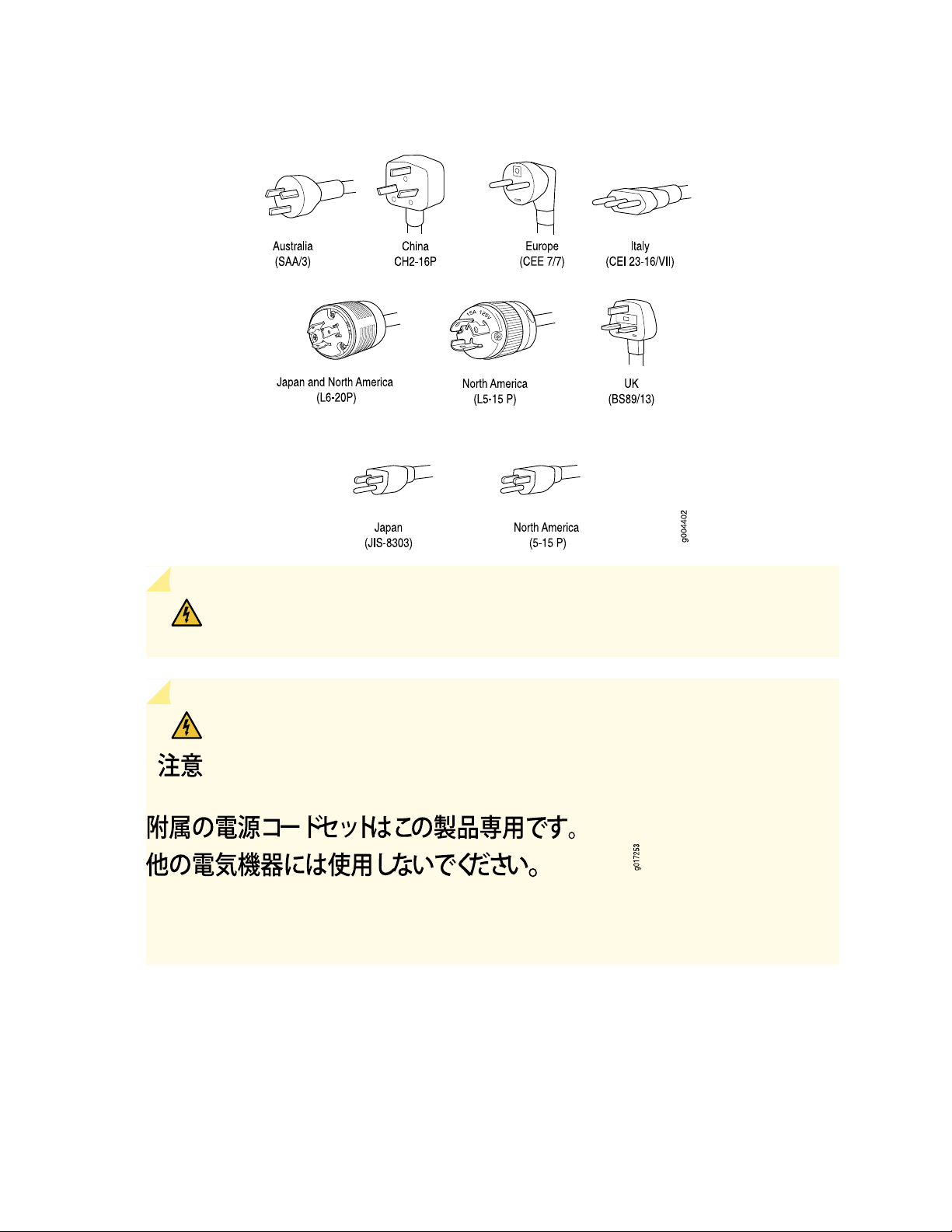
Figure 20: AC Plug Types
58
WARNING: The AC power cord for the switch is intended for use with the switch
only and not for any other use.
WARNING:
Translation from Japanese: The attached power cable is only for this product. Do not
use the cable for another product.
Page 59
NOTE: In North America, AC power cords must not exceed 4.5 m (approximately 14.75 ft) in
length, to comply with National Electrical Code (NEC) Sections 400-8 (NFPA 75, 5-2.2) and
210-52, and Canadian Electrical Code (CEC) Section 4-010(3). You can order AC power cords
that are in compliance.
WARNING: The switch is pluggable type A equipment installed in a restricted-access
location. It has a separate protective earthing terminal (sized for UNC 1/4-20 ground
lugs) provided on the chassis in addition to the grounding pin of the power supply cord.
This separate protective earthing terminal must be permanently connected to earth.
CAUTION: Power cords must not block access to switch components. We recommend
that you route all AC power cord cables through the power cord tray provided with
the switch.
59
AC Power Supply LEDs in an EX9208 Switch
An AC power supply has three LEDs on its faceplate. These LEDs display information about the status of
the AC power supply. The power supply status is also reflected in two LEDs on the craft interface. In
addition, a power supply failure triggers the major alarm LED on the craft interface.
Table 18 on page 59 describes the LEDs on an AC power supply in an EX9208 switch.
Table 18: AC Power Supply LEDs on EX9208 Switches
DescriptionColorLED
GreenAC OK
Off
AC power input is within range. Power supply is
functioning normally.
AC power input is below the range.Yellow
Indicates one of the following:
Power supply is disconnected from AC power
•
feed.
No AC power input.
•
Page 60

Table 18: AC Power Supply LEDs on EX9208 Switches (continued)
DescriptionColorLED
60
GreenDC OK
Off
RedPS FAIL
DC Power Supply in an EX9208 Switch
IN THIS SECTION
DC Power Supply Description | 61
DC power output generated by the power supply
is within the normal operating ranges.
DC power output generated by the power supply
is not within the normal operating ranges.
Power supply is not functioning normally and its
output voltage is out of regulation limits. Check
AC OK and DC OK LEDs for more information.
Power supply is functioning normally.Off
DC Power Supply Configurations | 61
An EX9208 switch is configurable with two or four DC power supplies. The power supplies connect to
the midplane, which distributes the different output voltages produced by the power supplies to the switch
components, depending on their voltage requirements. Each power supply is cooled by its own internal
cooling system.
CAUTION: EX9208 switches use either AC or DC power supplies. Do not mix AC and
DC power supplies in a switch. The first type of power supply detected by the switch
when initially powered on determines the type of power supply allowed by the switch.
All installed power supplies of the other type are disabled by the switch. If you install
a power supply of the other type while the switch is operating, the switch disables the
power supply and generates an alarm.
This topic describes the DC power supplies in EX9208 switches.
Page 61

DC Power Supply Description
The DC power supplies in EX9000 switches are hot-insertable and hot-removable field-replaceable units
(FRUs).
You can install either two or four DC power supplies in an EX9208 switch. Power supplies are installed in
the rear of the chassis in slots PEM0 through PEM3 (left to right).
Each DC power supply weighs approximately 6.2 lb (2.81 kg) and consists of one DC input (–48 VDC and
return), one 70 A (–48 VDC) circuit breaker, a fan, and LEDs to monitor the status of the power supply.
See Figure 21 on page 61.
Each DC power supply has a single DC input (–48 VDC and return) that requires a dedicated circuit breaker.
We recommend you provision 60 A or 75 A per feed, depending on the selected DIP switch setting. If you
plan to operate a maximally configured DC-powered switch with DC power supplies, we recommend that
you use a dedicated customer site circuit breaker rated for 70 A (–48 VDC) minimum, or as required by
local code.
If you plan to operate a DC-powered switch at less than the maximum configuration, we recommend that
you provision a circuit breaker according to respective National Electrical Code and customer site internal
standards to maintain proper level of protection for the current specified above or each DC power supply
rated for at least 125% of the continuous current that the system draws at –48 VDC.
61
Figure 21: DC Power Supply for an EX9208 Switch
DC Power Supply Configurations
In the DC power configuration, the EX9208 switch contains either two or four DC power supplies located
at the rear of the chassis in slots PEM0 through PEM3 (left to right). You can upgrade your DC power
system from two to four power supplies.
Page 62
Four power supplies provide full redundancy. If a DC power supply in a redundant configuration is removed
or fails, its redundant power supply takes over without interruption. The DC power supply in PEM2 serves
as redundant to the DC power supply in slot PEM0, and the DC power supply in PEM3 serves as redundant
to the DC power supply in slot PEM1. If only two DC power supplies are installed, they must be installed
in slots PEM0 and PEM1 or in slots PEM2 and PEM3.
Table 19 on page 62 shows the components that are powered by each DC power supply slot. It applies
to existing and high-capacity power supplies.
Table 19: Power Supply Redundancy and Power Distribution
Components That Are Supplied PowerDC Power Supply Slot
Fan tray, line card slots 0 and 1, and SF slots 0 and 1PEM0
Fan tray and line card slots 2 through 5PEM1
Fan tray, line card slots 0 and 1, and SF slots 0 and 1PEM2
62
Fan tray and line card slots 2 through 5PEM3
SEE ALSO
Installing a DC Power Supply in an EX9208 Switch | 209
DC Power Supply Specifications for EX9208 Switches
Table 20 on page 62 lists the DC power supply specifications for EX9208 switches.
Table 20: DC Power Supply Specifications for an EX9208 Switch
Item
DC input voltage
Specifications
Operating range:
Minimum operating range: –40.5 VDC
•
Nominal operating range: –48 VDC
•
Operating voltage range: –40.5 VDC to –72 VDC
•
70 A (DIP=1)60 A (DIP=0)Maximum Input Current
2600 W2400 WMaximum output power
Page 63

Table 20: DC Power Supply Specifications for an EX9208 Switch (continued)
63
Item
DC input current rating
Specifications
50 A @ –48 VDC normal operating
voltage
54.2 A @ –48 VDC normal operating
voltage
Table 21 on page 63 lists the power system specifications for EX9208 switches.
Table 21: DC Power System Specifications
Item
Specifications
2+2Redundancy
70 A (DIP=1)60 A (DIP=0)Output power (maximum) per supply
2600 W2400 W
5200 W4800 WOutput power (maximum) per system
DC Power Supply LEDs in an EX9208 Switch
A DC power supply has three LEDs on its faceplate: POWER OK, BRKR ON, and INPUT OK LEDs. The
power supply status is also reflected in two LEDs on the craft interface. In addition, a power supply failure
triggers the major alarm LED on the craft interface.
NOTE: A host subsystem must be present for the POWER OK LED to be on.
Table 22 on page 63 describes the LEDs on a DC power supply in EX9208 switches.
Table 22: DC Power Supply LEDs in EX9208 Switches
DescriptionColorLED
Power supply is functioning normally.GreenPOWER OK
The main output voltage is out of range.Yellow
Off
Power supply is not functioning normally. Check
the INPUT OK LED for more information.
Page 64
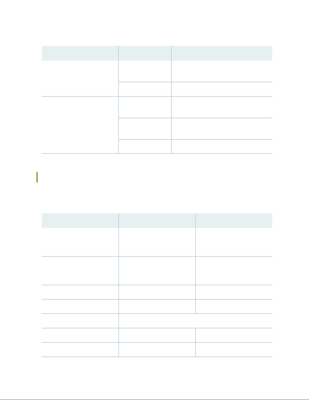
Table 22: DC Power Supply LEDs in EX9208 Switches (continued)
DescriptionColorLED
64
GreenBRKR ON
GreenINPUT OK
Yellow
DC power input is present and the DC power
supply circuit breaker is turned on.
DC power supply circuit breaker is turned off.Off
DC input is present and is connected in correct
polarity.
DC input is present, but is not in valid operating
range or connected in reverse polarity.
DC input to the power supply is not present.Off
Power Requirements for EX9200 Switch Components
Table 23 on page 64 lists the power requirements for different hardware components of EX9200 switches.
Table 23: EX9200 Switch Component Power Requirements
Base system
Redundant system
EX9204 switch: 410 W
•
EX9208 switch: 560 W
•
EX9214 switch: 1290 W
•
EX9204 switch: 690 W
•
EX9208 switch: 800 W
•
EX9214 switch: 1530 W
•
See “EX9200-SF3 Module in an EX9200 Switch” on page 77EX9200-SF3 Switch Fabric module
Reserved Power (watt)Typical Power (watt)Component
EX9204 switch: 410 W
•
EX9208 switch: 560 W
•
EX9214 switch: 1670 W
•
EX9204 switch: 690 W
•
EX9208 switch: 800 W
•
EX9214 switch: 1910 W
•
150 W150 WEX9200-SF Switch Fabric module
155 W155 WEX9200-SF2 Switch Fabric module
90 W90 WRouting Engine module (RE module)
610 W530 WEX9200-2C-8XS line card
Page 65

Table 23: EX9200 Switch Component Power Requirements (continued)
65
Reserved Power (watt)Typical Power (watt)Component
520 W408 WEX9200-4QS line card
607 W511 WEX9200-6QS line card
534 W461 WEX9200-MPC line card
29.8 W29.8 WEX9200-10XS-MIC
37 W37 WEX9200-20F-MIC
41 W41 WEX9200-40T-MIC
545 W465 WEX9200-12QS line card
See “EX9200-15C Line Card” on page 99EX9200-15C line card
EX9200 Host Subsystem
IN THIS SECTION
610 W550 WEX9200-32XS line card
239 W206 WEX9200-40T line card
239 W219 WEX9200-40F line card
239 W219 WEX9200-40F-M line card
545 W465 WEX9200-40XS line card
Host Subsystem in an EX9200 Switch | 66
Routing Engine Module in an EX9200 Switch | 67
Routing Engine Module LEDs in an EX9200 Switch | 70
Switch Fabric Module in an EX9200 Switch | 73
Page 66

Switch Fabric Module LEDs in an EX9200 Switch | 76
EX9200-SF3 Module in an EX9200 Switch | 77
Host Subsystem in an EX9200 Switch
Switching and routing functionality, system management, and system control functions of an EX9200
switch are performed by host subsystem. A host subsystem consists of a Routing Engine functioning
together with a Switch Fabric.
You can install either one or two host subsystems in the front panel of an EX9204 or an EX9208 switch.
A base configuration EX9204 and EX9208 switch has one host subsystem. A redundant configuration
EX9204 and EX9208 switch has a second host subsystem.
66
You can install either two or three host subsystems in the front panel of an EX9214 switch. A base
configuration EX9214 switch has two host subsystems. A redundant configuration EX9214 switch has a
third host subsystem.
NOTE: In EX9204 and EX9208 switches, we recommend that you install two host subsystems
for redundant protection. If you install only one host subsystem, we recommend that you install
it in slot 0. In EX9214 switches, we recommend that you install three host subsystems for
redundant protection. If you install only two host subsystems, we recommend that you install it
in slot 0 and 1.
Each host subsystem has LEDs in the craft interface that display its status. See Craft Interface in an EX9200
Switch.
SEE ALSO
Taking the Host Subsystem Offline in an EX9200 Switch | 212
Maintaining the Host Subsystem in EX9200 Switches | 230
Page 67

Routing Engine Module in an EX9200 Switch
The Routing Engine module (RE module) is an Intel-based platform that runs Juniper Networks Junos
operating system (Junos OS). Software processes that run on the RE module maintain the routing tables,
manage the routing protocols used on the switch, control the router interfaces and some of the chassis
components, and provide the interface for system management and user access to the switch.
In an EX9204, EX9208, or EX9214 switch, you can install one or two RE modules in the Switch Fabric
modules (SF modules) that are installed in slots on the front panel of the switch. If you install two RE
modules, one functions as the primary and the other functions as the backup. If the primary RE module
fails or is removed and the backup is configured appropriately, the backup takes over as the primary. The
backup RE module is hot-insertable and hot-removable, whereas the primary RE module is only
hot-insertable. See Figure 22 on page 68 and Figure 23 on page 69. A USB port on the RE module accepts
a USB memory card that loads the Junos OS.
NOTE:
In EX9214 switches, you must install an RE module only in the SF modules installed in slots 7
•
and 8 labeled 0 and 1.
67
If you have installed only one RE module, you must power off the switch before removing the
•
RE module.
A base-configuration EX9204, EX9208, or EX9214 switch has only one RE module. See EX9204 Switch
Configurations, “EX9208 Switch Configurations” on page 27, and EX9214 Switch Configurations. You can
add a second RE module to the configuration for redundancy.
NOTE: We recommend that you install two RE modules in EX9204, EX9208, and EX9214
switches for redundancy.
The RE module performs the following functions:
Provides switching functionality to the switch through the switching plane
•
Powers the line cards on and off
•
Controls system resets and the boot sequence for the switch
•
Monitors and controls the fan speed, power status for various chassis components, and craft interface
•
LEDs
The switch ships with the RE modules preinstalled. There are two copies of the software:
One copy on the solid-state drive (SSD) in the RE module.
•
Page 68

One copy on a USB flash drive that can be inserted into the slot on the RE module faceplate.
g022003
USB
port
Reset
button
Online
LED
Master
LED
OK/Fail
LED
Storage
LED
Extractor
clip
Extractor
clip
Console
port
Auxiliary
port
Ethernet
port
SSD
slot 2
SSD
slot 1
•
The RE module boots from the storage media in the following order: the USB device (if present), then the
SSD, and finally the LAN.
NOTE: Starting with Junos OS Release 17.1R1, EX9200 switches support the EX9200-RE2
module. The EX9200-RE2 module supports virtual machine (VM) architecture in an EX9200
switch. Only the EX9200-SF2 module supports the EX9200-RE2 module. Starting with Junos
OS Release 17.1R1, you cannot form a Virtual Chassis using an EX9200 switch.
CAUTION: The EX9200-RE module and the EX9200-RE2 module are not interoperable.
Do not install both the RE modules in the same switch chassis.
68
NOTE: Starting with Junos OS Release 16.1, you can use EX9200 switches as an aggregation
device in Junos Fusion Enterprise. Starting with Junos OS Release 17.4, you can use EX9200
switches with EX9200-RE2 module installed in it as an aggregation device in Junos Fusion
Enterprise. See Understanding Junos Fusion Enterprise Software and Hardware Requirements for
the list of line cards that support this configuration.
Figure 22 on page 68 shows the EX9200-RE module in an EX9200 switch.
Figure 22: EX9200-RE Module in an EX9200 Switch
Each EX9200-RE module consists of the following components:
Extractor clips—Control the locking system to securely install and remove the EX9200-RE module.
•
AUX port—Connects the EX9200-RE module to a modem or other auxiliary device.
•
Page 69

CONSOLE port—Connects the EX9200-RE module to a system console through a cable with an RJ-45
•
connector. See “Connecting an EX9200 Switch to a Management Console or an Auxiliary Device” on
page 181.
ETHERNET port—Connects the EX9200-RE module through an Ethernet connection to a management
•
LAN (or any other device that plugs into an Ethernet connection) for out-of-band management. See
“Connecting an EX9200 Switch to a Network for Out-of-Band Management” on page 180.
USB port—Hosts a removable media interface through which you can install the Junos OS manually. See
•
“USB Port Specifications for an EX Series Switch” on page 142.
SATA SSD 1 and SATA SSD 2 slots—Host primary storage for software images, configuration files, and
•
microcode. Also provide secondary storage for log files and memory dump files.
RESET button—Reboots the EX9200-RE module when pressed.
•
ONLINE/OFFLINE button—Turns the EX9200-RE module online or offline when pressed.
•
Status LEDs—Indicate the status of the EX9200-RE module. Each EX9200-RE module has four LEDs
•
labeled MASTER, STORAGE, ONLINE, and OK/FAIL on the faceplate.
69
Captive screws—Secure the EX9200-RE module in place.
•
Figure 23 on page 69 shows the EX9200-RE2 module in an EX9200 switch.
Figure 23: EX9200-RE2 Module in an EX9200 Switch
6—1— ONLINE/OFFLINE buttonExtractor clips
7—2— SSD LEDs—DISK1 and DISK2Auxiliary port (AUX)
8—3— USB ports—USB1 and USB2Console port (CONSOLE)
9—4— RESET buttonManagement port (MGMT)
10—5— SSD slots—SSD 1 and SSD 2LEDs—ONLINE, OK/FAIL, and MASTER
Each EX9200-RE2 module consists of the following components:
Extractor clips—Control the locking system to securely install and remove the EX9200-RE2 module.
•
AUX port—Connects the EX9200-RE2 module to a modem or other auxiliary device.
•
CONSOLE port—Connects the EX9200-RE2 module to a system console through a cable with an RJ-45
•
connector. See “Connecting an EX9200 Switch to a Management Console or an Auxiliary Device” on
page 181.
Page 70

MGMT port—Connects the EX9200-RE2 module through an Ethernet connection to a management
•
LAN (or any other device that plugs into an Ethernet connection) for out-of-band management. See
“Connecting an EX9200 Switch to a Network for Out-of-Band Management” on page 180.
Status LEDs—Indicate the status of the EX9200-RE2 module. Each EX9200-RE2 module has five LEDs
•
labeled MASTER, ONLINE, OK/FAIL, DISK1, and DISK2 on the faceplate.
ONLINE/OFFLINE button—Turns the EX9200-RE2 module online or offline when pressed.
•
USB1 and USB2 ports—Host a removable media interface using which you can install the Junos OS
•
manually. See “USB Port Specifications for an EX Series Switch” on page 142.
SSD 1 and SSD 2 slots—Host primary storage for software images, configuration files, and microcode.
•
Also provide secondary storage for log files and memory dump files.
RESET button—Reboots the EX9200-RE2 module when pressed.
•
Captive screws—Secure the EX9200-RE2 module in place.
•
For the specifications of the Routing Engine modules, see Table 24 on page 70.
Table 24: Routing Engine Module Specifications
70
Connection
First
Junos OS
ReleaseMediaDisk
12.3R24- GB
17.1R1No flash
EX9200-RE
EX9200-RE2
(4 cores, 1.73 GHz)
(6 cores, 2 GHz)
to Packet
Forwarding
EnginesMemoryProcessorRE Module
16 GBRE-S-EX9200-1800X4
64 GBRE-S-EX9200-2X00x6
Gigabit
Ethernet
Gigabit
Ethernet
32- GB hard
disk
50- GB SSD
X 2
CompactFlash
card
memory
Routing Engine Module LEDs in an EX9200 Switch
Each Routing Engine module (RE module) has LEDs on the module faceplate. Table 25 on page 71 describes
the functions of these LEDs on the EX9200-RE and Table 26 on page 71 describes the functions of these
LEDs on the EX9200-RE2.
Page 71

Table 25: LEDs on the EX9200-RE Routing Engine Module
State and DescriptionStatusLED Label
RE module is functioning as the primary.BlueMASTER
71
Unlit
GreenONLINE
RE module is either functioning as the backup or not
installed.
Blinking—Indicates activity on the SSD.GreenSTORAGE
On steadily—RE module is operating normally.
•
Blinking—RE module is coming online or going offline.
•
RE module has failed.RedOK/FAIL
Table 26: LEDs on the EX9200-RE2 Routing Engine Module
State and DescriptionStatusLED Label
RE module is functioning as the primary.BlueMASTER
Unlit
RE module is either functioning as the
backup or not installed.
Page 72

Table 26: LEDs on the EX9200-RE2 Routing Engine Module (continued)
State and DescriptionStatusLED Label
The RE is powered offUnlitONLINE
72
Green
When the RE module is powering on:
Blinking slowly (LED is lit for a period of
•
time and is unlit for thrice that period of
time that follows, and this pattern is
repeated)—RE module is coming online.
Blinking fast (LED is lit for a period of time
•
and is unlit for the subsequent same
period of time, and this pattern is
repeated)—Linux is booted.
On steadily (LED glows steadily)—Junos
•
OS is booted.
When the RE module is powering off:
Blinking fast (LED is lit for a period of time
•
and is unlit for the subsequent same
period of time, and this pattern is
repeated)—Junos OS is powering off.
Blinking slowly (LED is lit for a period of
•
time and is unlit for thrice that period of
time that follows, and this pattern is
repeated)—Linux is powering off.
Unlit—RE module is powered off.
•
RE module has failed.RedOK/FAIL
Blinking—Indicates activity on the SSD.GreenDISK1
Blinking—Indicates activity on the SSD.GreenDISK2
SEE ALSO
Installing an RE Module in an EX9200 Switch | 215
Removing an RE Module from an EX9200 Switch | 213
Page 73

Switch Fabric Module in an EX9200 Switch
The Switch Fabric serves as the central nonblocking matrix through which all network data passes.
Switch Fabric modules (SF modules) are installed horizontally on the front panel of the switch chassis. You
can install either one or two SF modules in an EX9204 or EX9208 switch and two or three SF modules in
an EX9214 switch. A base-configuration EX9204 or EX9208 switch has only one SF module, and a
base-configuration EX9214 switch has two SF modules. See EX9204 Switch Configurations, “EX9208 Switch
Configurations” on page 27, or EX9214 Switch Configurations.
In EX9204 and EX9208 switches, you can add a second SF module to the configuration for host subsystem
redundancy. In EX9214 switches, you can add a third SF module to the configuration for host subsystem
redundancy. If two SF modules are installed, one SF module functions as the primary and the other functions
as the backup. If the primary SF module or its components fails or is removed, the backup module takes
the role of primary.
The Routing Engine module (RE module) installs directly into a slot on the SF module. The Switch Fabric
contains logic that determines which Routing Engine is the primary. The primary Routing Engine controls
many internal functions of the SF module.
73
The backup SF module is hot-insertable and hot-removable, but the primary SF module is only hot-insertable.
The key functions of the Switch Fabric are:
Monitor and control system functions
•
Interconnection of all line cards
•
Clocking, system resets, and booting control
•
Routing Engine carrier
•
Figure 24 on page 74 shows the original SF module, EX9200-SF.
Page 74
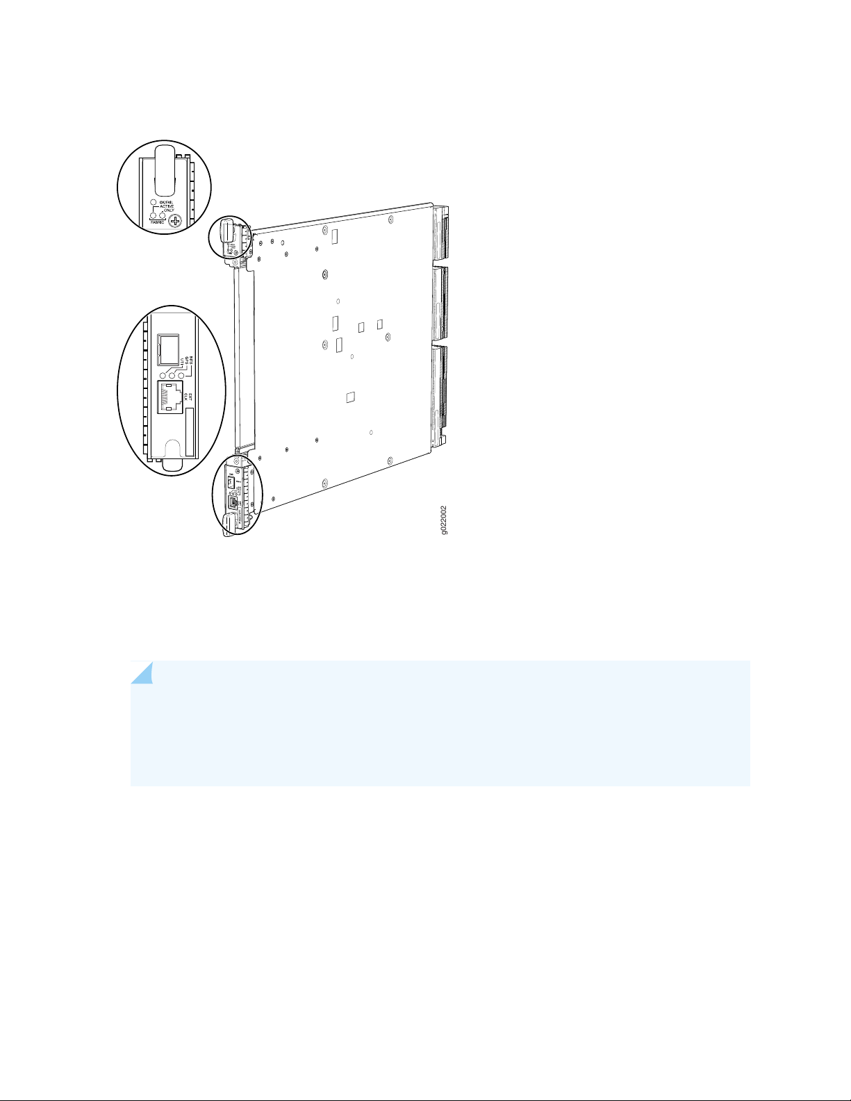
Figure 24: SF Module EX9200-SF
g022002
74
Starting with Junos OS Release 14.1, a high-speed SF module, EX9200-SF2, is available. Compared to the
original SF module, EX9200-SF, the EX9200-SF2 offers increased bandwidth, providing higher-capacity
traffic support in settings that require greater interface density (slot and capacity scale).
The EX9200-SF2 supports all EX9200 line cards.
NOTE: When you upgrade from an EX9200-SF module to an EX9200-SF2 module in an EX9200
switch, the SF module types can coexist in the switch during the upgrade. However, you must
replace that EX9200-SF module with another EX9200-SF2 module for normal switch operation.
See “Upgrading an EX9200-SF to an EX9200-SF2” on page 217.
Figure 25 on page 75 shows the high-speed SF module, EX9200-SF2.
Page 75
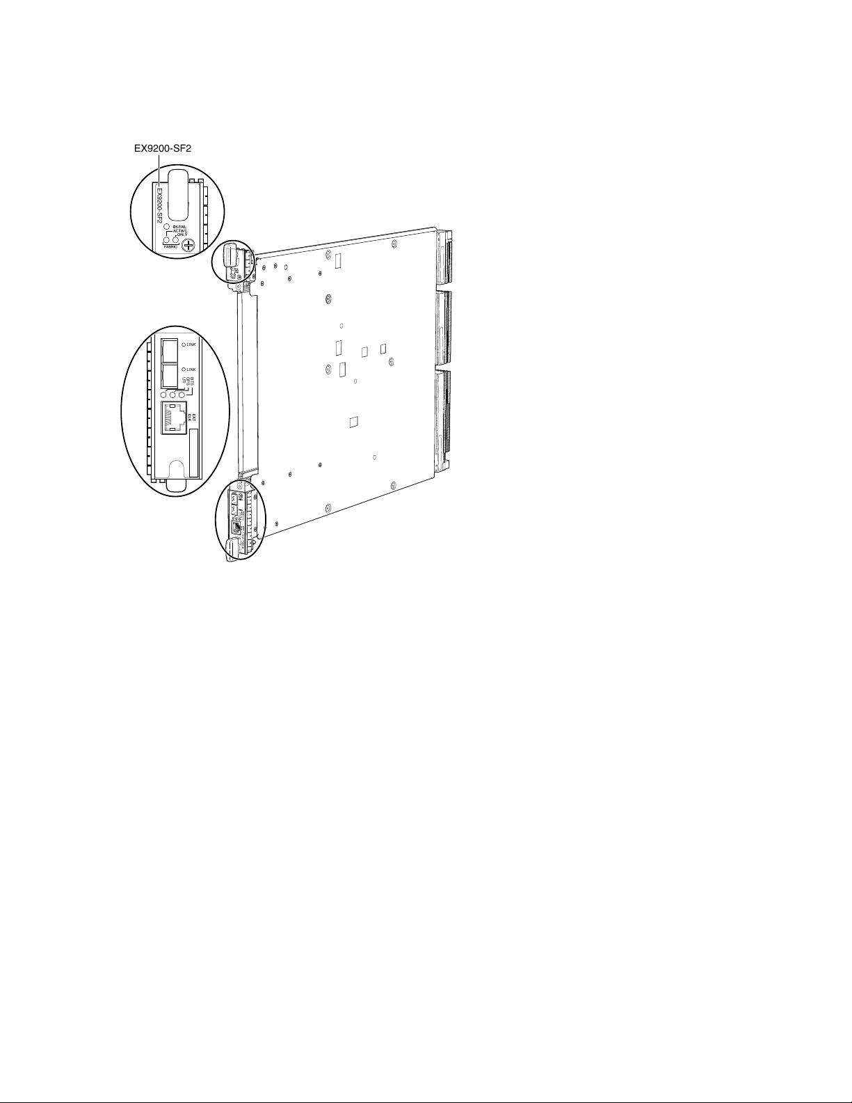
Figure 25: SF Module EX9200-SF2
EX9200-SF2
EX9200-SF2
LINK
LINK
BITS
GPS
UTI
EX9200-SF2
75
The SF modules install horizontally into the front of the chassis. If any slots are empty, you must install a
cover panel.
The SF module has the following components:
Chassis management Ethernet switch
•
I2C bus logic, used for low-level communication with each component
•
Component redundancy circuitry
•
Control Board/Routing Engine primary-role mechanism
•
Gigabit Ethernet switch that is connected to the embedded CPU complex on all components
•
Control field-programmable gate array (FPGA)—Provides the Peripheral Component Interconnect (PCI)
•
interface to the Routing Engine
1000Base-T Ethernet controller—Provides a 1-Gbps Ethernet link between the Routing Engines
•
Ethernet switch—Provides 1-Gbps link speeds between the Routing Engine and the line cards
•
External clock interface—Allows BITS or GPS clock source input to the centralized timing circuit, or
•
allows centralized timing to be output to BITS or GPS
Circuits for chassis management and control
•
Page 76

Power circuits for the Routing Engine and the Switch Fabric
•
SF module LEDs—Indicate system status. (See “Switch Fabric Module LEDs in an EX9200 Switch” on
•
page 76).
Ejector levers—Used for installing and removing the SF module
•
Captive screws—Secure the SF module in place
•
SEE ALSO
Installing an SF Module in an EX9200 Switch | 227
Removing an SF Module from an EX9200 Switch | 225
Taking the Host Subsystem Offline in an EX9200 Switch | 212
76
Switch Fabric Module LEDs in an EX9200 Switch
The Switch Fabric module (SF module) has three LEDs on the module faceplate. Table 27 on page 76
describes the functions of these LEDs. For information about the LEDs on the EX9200-SF3, see
Table 28 on page 79.
Table 27: SF Module LEDs of an EX9200 Switch
DescriptionStatusLED
Switch Fabric is in active mode.GreenFABRIC ACTIVE
Switch Fabric is offline.Unlit
On steadily—Switch Fabric is operating in fabric-only mode.GreenFABRIC ONLY
Switch Fabric is not operating in fabric-only mode.Unlit
Switch Fabric is online.GreenOK/FAIL
Switch Fabric has failed.Red
Switch Fabric is offline.Unlit
The BITS, GPS, and UTI LEDs, located next to the EXT CLK port, indicate the status of the respective
clocking interface. These LEDs are not supported.
Page 77
EX9200-SF3 Module in an EX9200 Switch
g100547
EX9200-SF3
Starting in Junos OS Release 20.3R1, the EX9200-SF3 Swith Fabric module is available. The EX9200-SF3
provides improved fabric performance and bandwidth capabilities for high-capacity line cards. In a redundant
configuration, the EX9200-SF3 provides fabric bandwidth of up to 1 Tbps per slot. In a nonredundant
configuration the EX9200-SF3 provides fabric bandwidth of up to 1 Tbps per slot (four fabric planes) and
1.5 Tbps per slot fabric bandwidth when all six fabric planes are used (with EX9200-15C line cards).
Figure 26 on page 77 shows the SF module, EX9200-SF3.
Figure 26: EX9200-SF3
77
The EX9200-SF3
Software release
Junos OS Release 20.3R1 and later
Name in CLI: EX9200-SF3
Page 78

EX9200-SF3 Components and Features
DescriptionComponent/Feature
78
XGE ports
GPS port
External clock interface
Centralized Stratum3E
clock module
In-system removable
Routing Engine
Two Ethernet ports provide 10GbE and 1GbE SFP+ interfaces. These ports also are
connected to the Ethernet control switch, which limits the traffic for the 10GbE port
and provides security to prevent unwanted access to the control plane through the
external ports.
One RJ-45 GPS external clock interface port receives GPS and PPS timing from the GPS
external interface. A red LED indicates there is no clock present or the clock is not OK.
A green LED indicates the clock interface is active and OK. If the LED is off, the clock
interface is not enabled.
The external clock interface is on the EX9200-SF3 front panel. The clock source interface
receives GPS and PPS timing from the GPS external interface.
The clock module performs clock monitoring, filtering, and holdover on the centralized
fabric card. This centralized clocking architecture also provides clock cleanup and
distribution.
The in-system Routing Engine can support any new Routing Engine that conforms to
the standard modular Routing Engine I/O interface and form factor.
NOTE: When a Routing Engine is not installed in the EX9200-SF3, you need to cover
the empty slot with a blank panel.
Hot-swappable
Redundancy
The EX9200-SF3 and associated Routing Engine assembly are hot-swappable. The
system software provides a mechanism to shut down the Routing Engine/EX9200-SF3.
The system software also provides a method to reset or reboot the Routing
Engine/EX9200-SF3. This support is provided through CLI commands and various
hardware support circuits.
NOTE: Before removing the module, you must bring the Routing Engine offline to avoid
corrupting the hard drive.
See “Upgrading to an EX9200-SF3” on page 221 for details.System upgrade capabilities
With three EX9200-SF3 Switch Fabric modules installed, the EX9214 provides 2 + 1
redundancy. With two EX9200-SF3s installed, the EX9204 and EX9208 provide 1 + 1
redundancy.
Supports dynamic multicast replication (DMR).DMR
Supports graceful Routing Engine switchover (GRES).GRES
Page 79
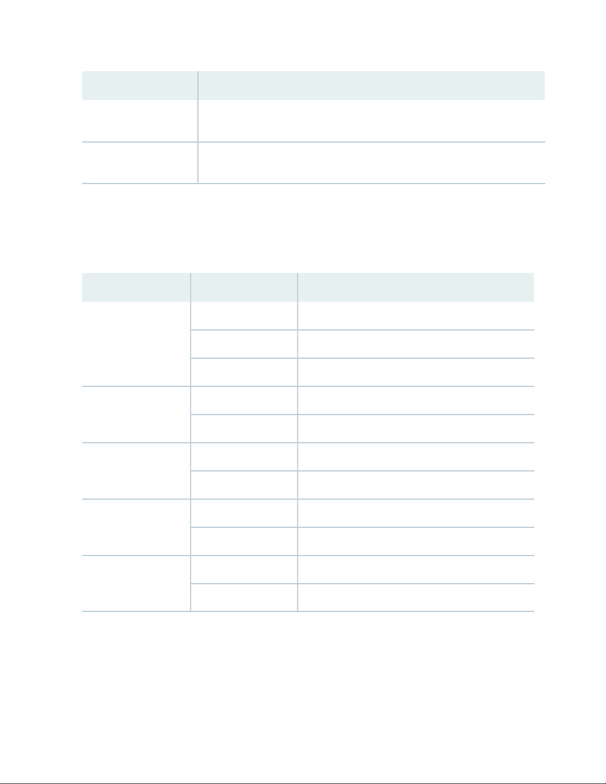
79
DescriptionComponent/Feature
Hitless operation
module
Allows you to upgrade programmable parts and reboot with “hitless” operation if the
redundant EX9200-SF3s are inserted in the system and are operational.
You can remove the Routing Engine module FRU in the existing form factor.Removable Routing Engine
EX9200-SF3 LEDs
Table 28 on page 79 describes the functions of the EX9200-SF3 LEDs.
Table 28: EX9200-SF3 Module LEDs
DescriptionStatusLED
Switch Fabric is online.GreenOK/FAIL
Switch Fabric has failed.Red
Switch Fabric is offline.Unlit
Switch Fabric is in active mode.GreenFABRIC ACTIVE
Switch Fabric is offline.Unlit
On steadily—Switch Fabric is operating in fabric-only mode.GreenFABRIC ONLY
Switch Fabric is not operating in fabric-only mode.Unlit
Port is enabled and a link is established.GreenXGE Port LINK
Port is disabled or no link is established.Unlit
A link is established.GreenGPS EXT CLK
There is activity on the clocking interface.Amber (blinking)
EX9200-SF3 Fabric Bandwidth Performance and Redundancy
EX9214 Switches:
Page 80

The EX9214 system can contain up to three EX9200-SF3s to provide a total of six switch fabric planes
•
for packet forwarding among the MPCs. Two fabric planes per EX9200-SF3s are required. To achieve
full fabric bandwidth performance, three EX9200-SF3s must be installed in the EX9214 chassis.
Two chassis slots are provided in the center of the EX9214 chassis in slots 6 and 7 (also designated as
•
slot SF0 and slot SF1) for two EX9200-SF3s, each equipped with a Routing Engine.
To provide 2 + 1 fabric redundancy for an EX9214, a third EX9200-SF3 must be installed in slot 8 (also
•
designated as slot SF2).
Slot 8 in the EX9214 chassis is a dual-purpose slot, and supports either an EX9200-SF3 or a line card.
•
When the EX9200-SF3/Routing Engine are plugged into slot 8, the Routing Engine is powered down
and does not provide any control functionality for the board or the EX9214. The fabric-only LED on the
card faceplate will be lit when an EX9200-SF3/Routing Engine assembly is plugged into slot 8.
Once redundancy is configured, the primary EX9200-SF3 controls the chassis.
•
Graceful upgrades can be achieved on a non-primary redundant EX9200-SF3.
•
In a redundant configuration, the non-primary redundant Routing Engine can be removed or installed
•
without affecting the switching plane functionality on the EX9200-SF3 in which it resides.
80
In a nonredundant configuration, all six fabric planes will be in active mode for increased fabric bandwidth.
•
There is one physical switch fabric per EX9200-SF3 and it acts as two virtual planes in the EX9214.
•
EX9204 and EX9208 Switches:
You can install either one or two EX9200-SF3s in the EX9204 and EX9208 chassis in the slots labeled
•
0 and 1.
The EX9200-SF3 in slot 0 (SF0) provides two fabric planes; the EX9200-SF3 in slot 1 (SF1) provides four
•
fabric planes. A total of six fabric planes are available in the EX9204 and EX9208.
In a redundant configuration, two fabric planes on the first EX9200-SF3 and two fabric planes on the
•
other EX9200-SF3 will be in active mode.
There is one physical switch fabric per EX9200-SF3, and it acts as four virtual planes in the EX9204 and
•
EX9208.
Two EX9200-SF3 modules installed in the EX9204 and EX9208 are required for 1 + 1 redundancy. To
provide 1 + 1 fabric redundancy, there must be an EX9200-SF3 installed in slot 1.
NOTE:
If SF0 fails, SF1 will be automatically configured with four fabric planes active. In this failover
•
scenario, the EX9200-SF3 will support full line rate 100 percent redundancy.
If SF1 fails, SF0 has only two available fabric planes; therefore, in this failover mode, the line
•
rate will drop to 50 percent.
Page 81

EX9200-SF3 Maximum Power Consumption per Ambient Temperature and CB Slot
NOTE: These power consumption values are for the EX9200-SF3 only. They do not include
reallocated power.
Maximum Power
ConsumptionAmbient TemperatureEX Series Model
Slot
81
EX9214
EX9208
EX9208
EX9204
131° F (55° C)
104° F (40° C)
77° F (25° C)
131° F (55° C)
104° F (40° C)
77° F (25° C)
131° F (55° C)
104° F (40° C)
77° F (25° C)
131° F (55° C)
104° F (40° C)
77° F (25° C)
SF0, SF1, SF2425 W
400 W
385 W
SF0 (primary)295 W
280 W
265 W
SF1 (backup)295 W
280 W
265 W
SF0 (primary)275 W
260 W
245 W
EX9204
131° F (55° C)
104° F (40° C)
77° F (25° C)
SF1 (backup)295 W
280 W
265 W
Page 82

Interoperability with Existing Hardware
Table 29: EX9200-SF3 Interoperabilitiy with Line Cards and Routing Engines
EX9200-SF3 Operating
Mode
Ethernet mode only
82
SupportedEX9204/EX9208/EX9214
NoEX9200-2C-8XSEnhanced IP/enhanced
NoEX9200-4QS
NoEX9200-6QS
YesEX9200-MPC
YesEX9200-12QS
YesEX9200-32XS
NoEX9200-40T
NoEX9200-40F
NoEX9200-40F-M
YesEX9200-40XS
Supported Routing Engines
EX9200-RE
EX9200-RE2
yes
yes
NOTE: Hyper-mode is the default forwarding mode on the EX9200-SF3. If your deployment
does not need hyper-mode, disable hyper-mode using the set forwarding-options no-hyper-mode
CLI command before installing the Routing Engine into the EX9200-SF3.
NOTE: Enhanced IP is the default network service on the EX9200-SF3.
Page 83

EX9200-SF3 Unsupported Functions and Capabilities from Legacy Swith Fabric Modules
The EX9200-SF3 does not support the external UTI/DTI interface (front panel LED and daughter card
•
interface).
The EX9200-SF3 does not interoperate with any previous generation SF modules (EX9200-SF and
•
EX9200-SF2). Smooth upgrade is not supported.
The EX9200-SF3 does not support BITS.
•
The EX9200-SF3 does not support DPCs.
•
The EX9200-SF3 does not support mixed mode (DPC + MPC).
•
The EX9200-SF3 does not support the JAM release.
•
SEE ALSO
Upgrading to an EX9200-SF3 | 221
83
Installing an SF Module in an EX9200 Switch | 227
Removing an SF Module from an EX9200 Switch | 225
Taking the Host Subsystem Offline in an EX9200 Switch | 212
EX9200 Line Cards
IN THIS SECTION
Line Card Model and Version Compatibility in an EX9200 Switch | 84
EX9200-2C-8XS Line Card | 87
EX9200-4QS Line Card | 89
EX9200-6QS Line Card | 90
EX9200-MPC Line Card | 93
EX9200-12QS Line Card | 96
EX9200-15C Line Card | 99
EX9200-32XS Line Card | 103
EX9200-40T Line Card | 104
EX9200-40F Line Card | 106
Page 84

EX9200-40F-M Line Card | 107
EX9200-40XS Line Card | 109
Line Card LED in an EX9200 Switch | 111
Network Port LEDs on Line Cards in an EX9200 Switch | 111
Modular Interface Card LED in an EX9200 Switch | 112
Configuring Rate Selectability on an EX9200-12QS Line Card to Enable Different Port Speeds | 113
Line Card Model and Version Compatibility in an EX9200 Switch
NOTE: If you are installing line cards released after Junos OS Release 14.1, ensure that the
Switch Fabric module (SF module) EX9200-SF2 is installed in the switch chassis.
84
Table 30 on page 84 shows the model numbers, description of the line card, the Junos OS release in which
the line card was first supported and the Switch Fabric module (SF module) that must be installed in the
switch to support each line card.
Table 30: Line Card Models for EX9200 Switches
First Junos OS
SF Module Required
EX9200-SF or
EX9200-SF2
EX9200-SF or
EX9200-SF2
EX9200-2C-8XS
EX9200-4QS
ReleaseDescriptionModel number
13.2R1A line card with two 100-Gigabit
Ethernet ports and eight 10-Gigabit
Ethernet ports
See “EX9200-2C-8XS Line Card” on
page 87
12.3R2A line card with four 40-Gigabit
Ethernet ports
See “EX9200-4QS Line Card” on
page 89
Page 85

Table 30: Line Card Models for EX9200 Switches (continued)
First Junos OS
ReleaseDescriptionModel number
85
SF Module Required
EX9200-6QS
EX9200-MPC
A line card with six 40-Gigabit
Ethernet ports and 24 10-Gigabit
Ethernet ports
See “EX9200-6QS Line Card” on
page 90
of the following MICs:
EX9200-10XS-MIC
•
EX9200-20F-MIC
•
EX9200-40T-MIC
•
14.2R1
CAUTION: Junos OS
Release 14.2R1 supports
the EX9200-6QS line
card except for one
specific configuration.
See the Junos OS
14.2R2 Release Notes
for Known Issue
PR1068396 to
determine whether that
configuration applies to
your switch and which
release to use if the
configuration applies.
15.1R3A modular line card that accepts any
EX9200-SF or
EX9200-SF2
EX9200-SF,
EX9200-SF2, or
EX9200-SF3
EX9200-12QS
EX9200-15C
See “EX9200-MPC Line Card” on
page 93
Ethernet rate-selectable ports, each
of which can house transceivers
See “EX9200-12QS Line Card” on
page 96
ports. All ports can operate at
10-Gbps, 25-Gbps, 40-Gbps, or
100-Gbps speeds
See “EX9200-15C Line Card” on
page 99
16.1R1A line card with 12 40-Gigabit
EX9200-SF2 or
EX9200-SF3
EX9200-SF320.3R1A line card with 15 rate-selectable
Page 86

Table 30: Line Card Models for EX9200 Switches (continued)
First Junos OS
ReleaseDescriptionModel number
86
SF Module Required
EX9200-32XS
EX9200-40T
EX9200-40F
EX9200-40F-M
Ethernet ports
See “EX9200-32XS Line Card” on
page 103
10/100/1000BASE-T ports that
support RJ-45 connectors
See “EX9200-40T Line Card” on
page 104
ports
See “EX9200-40F Line Card” on
page 106
ports with Media Access Control
Security (MACsec) capability
12.3R2A line card with 32 10-Gigabit
12.3R2A line card with 40
12.3R2A line card with 40 1-Gigabit Ethernet
14.2R1A line card with 40 1-Gigabit Ethernet
EX9200-SF,
EX9200-SF2, or
EX9200-SF3
EX9200-SF or
EX9200-SF2
EX9200-SF or
EX9200-SF2
EX9200-SF or
EX9200-SF2
See “EX9200-40F-M Line Card” on
page 107
EX9200-40XS
16.1R1A line card with 40 10-Gigabit
Ethernet ports with Media Access
Control Security (MACsec) capability,
each of which can house 10-gigabit
small form-factor pluggable plus
(SFP+) transceivers
See “EX9200-40XS Line Card” on
page 109
EX9200-SF2 or
EX9200-SF3
Ensure that all of the line cards in a switch are supported in the Junos OS release that you want to use.
Page 87

EX9200-2C-8XS Line Card
IN THIS SECTION
Line Card Models | 87
Line Card Components | 88
The line cards in EX9200 switches combine a Packet Forwarding Engine and Ethernet interfaces in a single
assembly. Line cards are field-replaceable units (FRUs) that you can install in the line card slots on the front
of the switch chassis. Line cards are hot-insertable and hot-removable: You can remove and replace them
without powering off the switch or disrupting switch functions.
Line Card Models
87
Table 31 on page 87 shows the model number, description of the line card model, and the Junos OS release
in which the line card was first supported.
Table 31: EX9200-2C-8XS Line Card
Junos OS Release
RequiredDescriptionModel
EX9200-2C-8XS
can house 100-gigabit C form-factor pluggable (CFP) transceivers;
and eight 10-Gigabit Ethernet ports, each of which can house
10-gigabit small form-factor pluggable plus (SFP+) transceivers
13.2R1 or laterA line card with two 100-Gigabit Ethernet ports, each of which
See Figure 27 on page 88
Page 88

Figure 27: EX9200-2C-8XS Line Card
4—1— 100-Gigabit Ethernet portsEjector levers
5—2— LEDs for the 100-Gigabit Ethernet portsLine card LED
6—3— 10-Gigabit Ethernet portsLEDs for the 10-Gigabit Ethernet ports
You can use the show version command to see the version of Junos OS for EX Series switches loaded on
the switch.
Line Card Components
88
The EX9200-2C-8XS line card has:
Two 100-Gigabit Ethernet ports, each of which can house CFP transceivers. These ports support
•
100GBASE-LR4 and 100GBASE-SR10 transceivers.
Eight 10-Gigabit Ethernet ports, each of which can house SFP+ transceivers. These ports support
•
10GBASE-SR, 10GBASE-LR, 10GBASE-ER, and 10GBASE-ZR transceivers.
Two dust covers for the two 100-Gigabit Ethernet ports and eight dust covers for the eight 10-Gigabit
•
Ethernet ports
Line card LED—An LED labeled OK/FAIL, which indicates the status of the line card. See “Line Card LED
•
in an EX9200 Switch” on page 111.
LEDs for the ports—One LED on each port, the Link/Activity LED, which indicates the link status and
•
activity on the port. See “Network Port LEDs on Line Cards in an EX9200 Switch” on page 111.
The ports are divided into two port groups. The four 10-Gigabit Ethernet ports labeled 0/0 through 0/3
and the 100-Gigabit Ethernet port labeled 1/0 form one port group. The four 10-Gigabit Ethernet ports
labeled 2/0 through 2/3 and the 100-Gigabit Ethernet port labeled 3/0 form the other port group. The
ports in each group share 130 gigabits of bandwidth. Thus, you can transmit up to 130 gigabits of traffic
through a port group, without packet drop.
Page 89
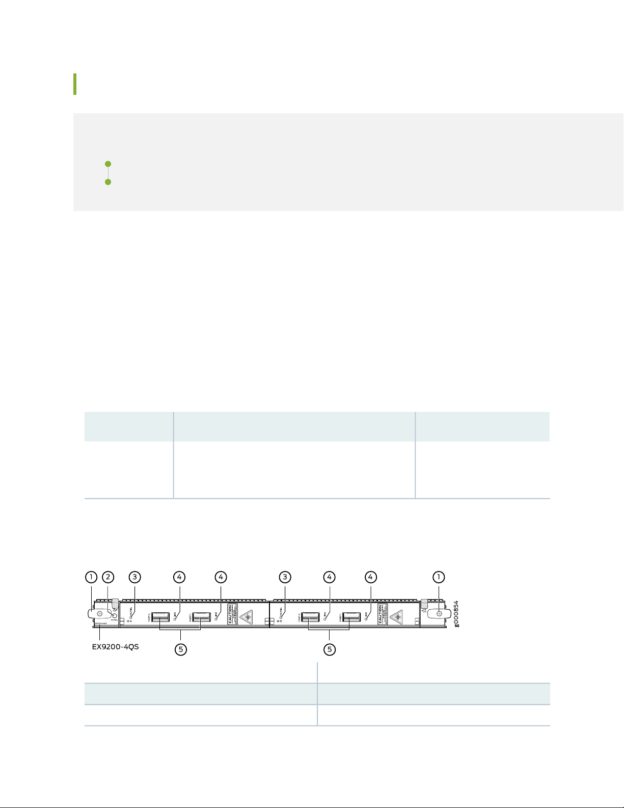
EX9200-4QS Line Card
IN THIS SECTION
Line Card Models | 89
Line Card Components | 90
The line cards in EX9200 switches combine a Packet Forwarding Engine and Ethernet interfaces on a single
assembly. They are field-replaceable units (FRUs) that you can install in the line card slots on the front of
the switch chassis. Line cards are hot-insertable and hot-removable: You can remove and replace them
without powering off the switch or disrupting switch functions.
Line Card Models
89
Table 32 on page 89 shows the model number, description of the line card model, and the Junos OS release
in which the line card was first supported.
Table 32: EX9200-4QS Line Card
Junos OS Release RequiredDescriptionModel
EX9200-4QS
which can house 40-gigabit quad small form-factor
pluggable plus (QSFP+) transceivers
12.3R2 or laterA line card with four 40-Gigabit Ethernet ports, each of
See Figure 28 on page 89.
Figure 28: EX9200-4QS Line Card
3—MIC LED
4—1— LEDs for the portsEjector lever
5—2— 40-Gigabit Ethernet portsLine card LED
Page 90
You can use the show version command to see the version of Junos OS for EX Series switches loaded on
the switch.
Line Card Components
The EX9200-4QS line card has:
Four 40-Gigabit Ethernet ports, each of which can house QSFP+ transceivers.
•
Four dust covers preinstalled in the ports.
•
Line card LED—An LED labeled OK/FAIL, which indicates the status of the line card. See “Line Card LED
•
in an EX9200 Switch” on page 111.
MIC LED—An LED labeled OK/FAIL on each MIC, which indicates the status of the MIC. See “Modular
•
Interface Card LED in an EX9200 Switch” on page 112.
LEDs for the ports—One LED on each port, the Link/Activity LED, which indicates the link status and
•
activity on the port. See “Network Port LEDs on Line Cards in an EX9200 Switch” on page 111.
90
EX9200-6QS Line Card
IN THIS SECTION
Line Card Models | 90
Line Card Components | 91
The line cards in EX9200 switches combine a Packet Forwarding Engine and Ethernet interfaces in a single
assembly. Line cards are field-replaceable units (FRUs) that you can install in the line card slots on the front
of the switch chassis. Line cards are hot-insertable and hot-removable: You can remove and replace them
without powering off the switch or disrupting switch functions.
Line Card Models
Table 33 on page 91 shows the model number, description of the line card model, and the Junos OS release
in which the line card was first supported.
Page 91
Table 33: EX9200-6QS Line Card
91
Junos OS Release RequiredDescriptionModel
EX9200-6QS
A line card with six 40-Gigabit Ethernet ports,
each of which can house 40-gigabit quad
small form-factor pluggable plus (QSFP+)
transceivers; and 24 10-Gigabit Ethernet
ports, each of which can house 10-gigabit
small form-factor pluggable (SFP+)
transceivers
See Figure 29 on page 91.
Figure 29: EX9200-6QS Line Card
14.2R1 or later
CAUTION: Junos OS Release 14.2R1 supports the
EX9200-6QS line card except for one specific
configuration. See the Junos OS 14.2R2 Release
Notes for Known Issue PR1068396 to determine
whether that configuration applies to your switch
and which release to use if the configuration does
apply.
4—1— 10-Gigabit Ethernet portsEjector lever
5—2— LEDs for the 40-Gigabit Ethernet portsLine card LED
6—3— 40-Gigabit Ethernet portsLEDs for the 10-Gigabit Ethernet ports
You can use the show version command to see the version of Junos OS for EX Series switches loaded on
the switch.
Line Card Components
The EX9200-6QS line card has:
Six 40-Gigabit Ethernet ports, each of which can house QSFP+ transceivers. These ports support
•
40GBASE-LR4 and 40GBASE-SR4 transceivers. Starting with Junos OS for EX Series switches,
Release 15.1 R3, these ports support the JNP-QSFP-40G-LX4 transceiver.
24 10-Gigabit Ethernet ports, each of which can house SFP+ transceivers. These ports support
•
10GBASE-SR, 10GBASE-LR, 10GBASE-ER, and 10GBASE-ZR transceivers.
Page 92

Line card LED—An LED labeled OK/FAIL, which indicates the status of the line card. See “Line Card LED
•
in an EX9200 Switch” on page 111.
Network port LED—One LED on each network port, the Link/Activity LED, which indicates the link
•
status and activity on the port. See “Network Port LEDs on Line Cards in an EX9200 Switch” on page 111.
You can install SFP+ and QSFP+ transceivers in any combination in the ports on the line card. The ports
are divided into two port groups. The twelve 10-Gigabit Ethernet ports labeled 0/0 through 0/11 form
PIC 0 and twelve 10-Gigabit Ethernet ports labeled 1/0 through 1/11 form PIC 1; PIC 0 and PIC 1 form
one port group. The three 40-Gigabit Ethernet ports labeled 2/0 through 2/2 form PIC 2 and three
40-Gigabit Ethernet ports labeled 3/0 through 3/2 form PIC 3; PIC 2 and PIC 3 form the other port group.
The ports in each port group share 240 gigabits of bandwidth. Thus, you can transmit up to 240 gigabits
of traffic through a port group, without packet drop.
PIC 0 and PIC 1 are activated by default. If you deactivate both PIC 0 and PIC 1, PIC 2 and PIC 3 are
automatically activated. Similarly, if you deactivate both PIC 2 and PIC 3, PIC 0 and PIC 1 are automatically
activated. You can choose to activate only one of the PICs and keep the other inactive. To deactivate an
active PIC, use the power command.
92
The line card supports the following combinations of active PICs:
Any one PIC
•
PIC 0 and PIC 1
•
PIC 0 and PIC 3
•
PIC 1 and PIC 2
•
PIC 2 and PIC 3
•
NOTE:
The line card does not support the following combinations of active PICs:
PIC 0 and PIC 2
•
PIC 1 and PIC 3
•
Page 93

EX9200-MPC Line Card
IN THIS SECTION
Line Card Models | 93
Line Card Components | 94
Line Card Models
Table 34 on page 93 shows the model number, description of the line card model, and the Junos OS release
in which the line card was first supported.
Table 34: EX9200-MPC
93
EX9200-MPC
(MICs):
EX9200-10XS-MIC
•
EX9200-20F-MIC
•
EX9200-40T-MIC
•
The MICs are separately orderable.
The EX9200-MPC line card has two slots on the faceplate in which you can
install the MICs. You can install the MICs in the following configurations:
One EX9200-10XS-MIC
•
One EX9200-20F-MIC
•
One EX9200-10XS-MIC and one EX9200-20F-MIC
•
Two EX9200-10XS-MICs
•
Two EX9200-20F-MICs
•
One EX9200-40T-MIC
•
Junos OS
Release
RequiredDescriptionModel
15.1R3A modular line card that accepts any of the following Modular Interface Cards
You can transmit up to 130 gigabits of traffic through the line card without
packet drop.
See Figure 30 on page 94.
Page 94
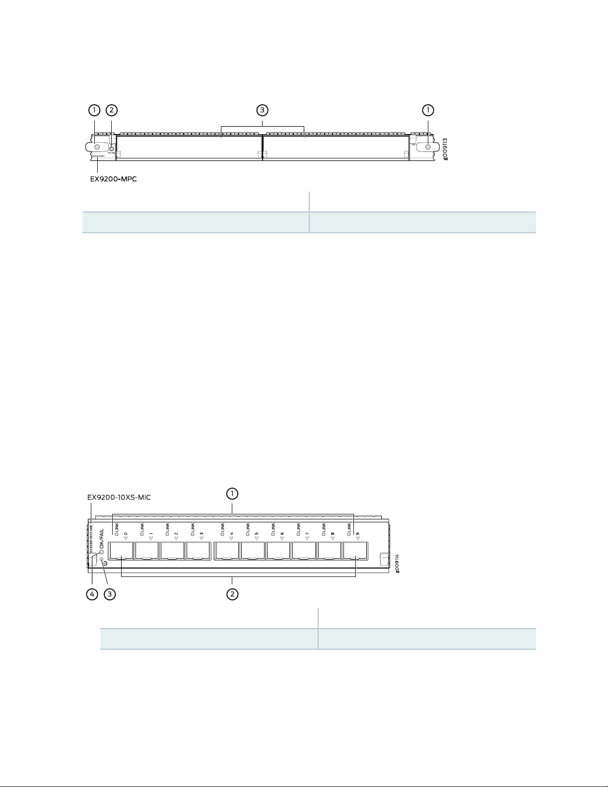
Figure 30: EX9200-MPC Line Card
3—1— MIC slots covered by cover panelsEjector lever
2—Line card LED
You can use the show version command to see the version of Junos OS for EX Series switches loaded on
the switch.
Line Card Components
The EX9200-MPC line card has:
94
Two slots that can accept any of the following MICs:
•
EX9200-10XS-MIC, which has ten 10-Gigabit Ethernet ports, each of which can house small form-factor
•
pluggable plus (SFP+) transceivers. The ports form one port group. The ports support 10GBASE-SR,
10GBASE-LR, 10GBASE-ER, and 10GBASE-ZR transceivers. An LED labeled OK/FAIL on the MIC
indicates the status of the MIC. See “Modular Interface Card LED in an EX9200 Switch” on page 112.
The MIC is shipped with 10 dust covers for the 10 ports. See Figure 31 on page 94.
Figure 31: EX9200-10XS-MIC
3—1— MIC power buttonLEDs for the ports
4—2— MIC LED10-Gigabit Ethernet ports
EX9200-20F-MIC, which has twenty 1-Gigabit Ethernet ports with Media Access Control Security
•
(MACsec) capability, each of which can house 1-gigabit small form-factor pluggable (SFP) transceivers.
The EX9200-20F-MIC in EX9200-MPC line card supports 802.1AE IEEE MAC Security standard (also
Page 95
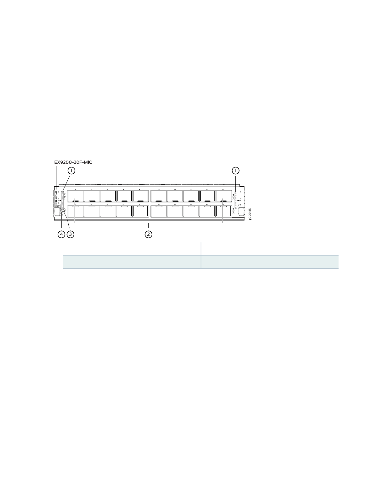
known as MACsec) with AES-128 bit encryption, providing support for link-layer data confidentiality,
data integrity, and data origin authentication. You must apply a single license—EX9200-SFL—to enable
MACsec. The ports are divided into two port groups of ten ports each. The ports labeled [0/2]/0
through [0/2]/8 and [1/3]/0 through [1/3]/8 form one port group and the ports labeled [0/2]/1
through [0/2]/9 and [1/3]/1 through [1/3]/9 form another port group. These ports support
1000BASE-T, 1000BASE-SX, 100BASE-FX, 1000BASE-LX, 1000BASE-BX-U, 1000BASE-BX-D,
100BASE-BX-U, 100BASE-BX-D, and 1000BASE-LH transceivers. An LED labeled OK/FAIL on the
MIC indicates the status of the MIC. See “Modular Interface Card LED in an EX9200 Switch” on
page 112. The MIC is shipped with 20 dust covers for the 20 ports. See Figure 32 on page 95.
Figure 32: EX9200-20F-MIC
95
3—1— MIC LEDLEDs for the ports
4—2— MIC power button1-Gigabit Ethernet ports
EX9200-40T-MIC, which has 40 RJ-45 ports, which can accept RJ-45 connectors. The ports are divided
•
into three port groups. The ports labeled 0/1 through 1/5 and 0/0 through 1/4 form port group pic0,
the ports labeled 1/7 through 2/3 and 1/6 through 2/2 form port group pic1, and the ports labeled
2/5 through 3/9 and 2/4 through 3/8 form port group pic2. An LED labeled OK/FAIL on the MIC
indicates the status of the MIC. See “Modular Interface Card LED in an EX9200 Switch” on page 112.
See Figure 33 on page 96.
Page 96

Figure 33: EX9200-40T-MIC
4—1— MIC power buttonLink/Activity LED for the ports
5—2— MIC LEDStatus LED the ports
3—RJ-45 ports
Cover panels—Two cover panels that cover the MIC slots.
•
Line card LED—An LED labeled OK/FAIL, which indicates the status of the line card. See “Line Card LED
•
in an EX9200 Switch” on page 111.
96
Network port LEDs—Each port on the EX9200-10XS-MIC and each port on the EX9200-20F-MIC has
•
an LED, the Link/Activity LED, which indicates the link status and activity on the port. Each port on the
EX9200-40T-MIC has another LED, the Status LED, which indicates the status of the port parameters.
See “Network Port LEDs on Line Cards in an EX9200 Switch” on page 111.
EX9200-12QS Line Card
IN THIS SECTION
Line Card Models | 97
Line Card Components | 98
The line cards in EX9200 switches combine a Packet Forwarding Engine and Ethernet interfaces in a single
assembly. Line cards are field-replaceable units (FRUs) that you can install in the line card slots on the front
of the switch chassis. Line cards are hot-insertable and hot-removable: You can remove and replace them
without powering off the switch or disrupting switch functions.
Page 97

Line Card Models
g0 0 9 282
0/3
0/ 0
0/4
0/5
0/3
0/4
0/5
100G
100G
0 1 2 3
0 1 2 3
0/ 1
0/2
0/0
0/ 1
0/ 2
1/0
1/1
1/2
1/0
1/1
1/2
100G
0
1
2 3
1/3
1/4
1/5
1/3
1/4
1/5
100G
0
1
2 3
1 2 3 3 3 34 4 4 4 1
EX9 200 -12QS
Table 35 on page 97 shows the model number, description of the line card model, and the Junos OS release
in which the line card was first supported.
Table 35: EX9200-12QS Line Card
Junos OS Release
RequiredDescriptionModel
97
EX9200-12QS
16.1R1 or laterA line card with 12 rate-selectable ports, each of which
can house transceivers. All ports can operate at 10-Gbps
and 40-Gbps speeds. The ports are configured to operate
at 10-Gbps speed by default. The ports labeled 0/2, 0/5,
1/2, and 1/5 (see Figure 34 on page 97) can operate at
100-Gbps speed also. The line card supports maximum
transmission units (MTUs) from 256 bytes through 9192
bytes.
NOTE: For the EX9200-12QS line card to be operational, you must install the EX9200-SF2 Switch Fabric module
(SF module) in the switch. See “Switch Fabric Module in an EX9200 Switch” on page 73 and “Installing an SF Module
in an EX9200 Switch” on page 227.
Figure 34 on page 97 shows the components of an EX9200-12QS line card.
Figure 34: EX9200-12QS Line Card
3—1— 10G/40G/100G Ethernet portsEjector lever
Line card LEDs
4—2— Link/Activity LEDs for the 10G/40G/100G Ethernet
ports
You can use the show version command to see the version of Junos OS for EX Series switches loaded on
the switch.
Page 98

Line Card Components
The EX9200-12QS line card has:
Twelve rate-selectable Gigabit Ethernet ports. All ports can operate at 10-Gbps and 40-Gbps speeds.
•
The ports are configured to operate at 10-Gbps speed by default. The ports labeled 0/2, 0/5, 1/2, and
1/5 (see Figure 34 on page 97) can operate at 100-Gbps speed also. You can configure the port speed
by using the following command:
user@host# set chassis fpc fpc-slot pic pic-number pic-mode pic-speed number of ports
number-of-active-physical-ports
You can configure a port to operate at 10-Gbps speed. If you configure the ports to operate at 10-Gbps
•
speed, each port operates as four 10-Gbps interfaces.
You can configure a port to operate at 40-Gbps speed and install a 40-gigabit QSFP+ transceiver in
•
the port.
You can configure the ports labeled 0/2, 0/5, 1/2, and 1/5 (see Figure 34 on page 97) to operate at
•
100-Gbps speed and install 100-gigabit QSFP+ transceivers in these ports.
98
Twelve dust covers for the ports
•
Line card LED—An LED labeled OK/FAIL, which indicates the status of the line card. See “Line Card LED
•
in an EX9200 Switch” on page 111.
Network port LED—Four LEDs for each network port, the Link/Activity LED, which indicates the link
•
status and activity on the port. See “Network Port LEDs on Line Cards in an EX9200 Switch” on page 111.
There are four LEDs labeled 0, 1, 2, and 3 for each port (see Figure 34 on page 97). If a port is configured
to operate at 10-Gbps speed, four 10-Gbps interfaces are created and the LEDs labeled 0, 1, 2, and 3
for that port becomes operational. Each of these LEDs indicates the link/activity on each interface on
the corresponding port. If a port is configured to operate at 40-Gbps speed, the LED labeled 0 for that
port becomes operational. If the ports labeled 0/2, 0/5, 1/2, and 1/5 are configured to operate at
100-Gbps speed, the LED labeled 3 for each of these ports becomes operational.
You can find the list of transceivers supported on the EX9200-12QS line card at the Hardware Compatibility
Tool page for the EX9200-12QS line card.
The ports are divided into two port groups. The six ports labeled 0/0 through 0/5 form one port group,
PIC 0. The six ports labeled 1/0 through 1/5 form the other port group, PIC 1. The ports in each group
share 240 gigabits of bandwidth. Thus, you can transmit up to 240 gigabits of traffic through a port group
without packet drop.
Page 99

EX9200-15C Line Card
IN THIS SECTION
Line Card Models | 99
Line Card Components | 101
EX9200-15C Power Requirements | 101
EX9200-15C LEDs | 102
Cables and Connectors | 102
The line cards in EX9200 switches combine a Packet Forwarding Engine and Ethernet interfaces in a single
assembly. Line cards are field-replaceable units (FRUs) that you can install in the line card slots on the front
of the switch chassis. Line cards are hot-insertable and hot-removable: You can remove and replace them
without powering off the switch or disrupting switch functions.
99
Line Card Models
Table 36 on page 100 shows the model number, description of the line card model, and the Junos OS release
in which the line card was first supported.
Page 100

Table 36: EX9200-15C Line Card
100
EX9200-15C
Fixed-configuation line card with 15 rate-selectable
•
ports. All ports can operate at 10-Gbps, 25-Gbps,
40-Gbps, or 100-Gbps speeds. The ports are
configured to operate at 100-Gbps speed by
default.
Line-rate throughput of up to 1.5 Tbps when
•
installed with an enhanced midplane.
NOTE: In the CLI, when you run the show chassis
hardware command, the midplane description will
say <platform>-BP3 for an enhanced midplane. The
EX9214 only uses enhanced midplanes.
Line-rate throughput of up to 800 Gbps when
•
installed with a standard midplane.
NOTE: In the CLI, when you run the show chassis
hardware command, the midplane description will
say <platform>-BP for a standard midplane.
Junos OS Release
RequiredDescriptionModel
Name In
the CLI
EX9200-15C20.3R1 or later
Supports maximum transmission units (MTUs) from
•
256 bytes through 16,000 bytes for transit traffic,
and from 256 bytes through 9500 bytes for
host-bound packets.
NOTE:
For the EX9200-15C line card to be operational, you must install the EX9200-SF3 Switch
•
Fabric module (SF module) in the switch. See “EX9200-SF3 Module in an EX9200 Switch” on
page 77.
To achieve maximum line-rate performance, the line card’s fabric redundancy mode must be
•
configured in increased bandwidth mode.
To achieve maximum performance, the following number of EX9200-SF3 SF modules must
•
be installed in the system:
EX9214—Three EX9200-SF3 SF modules
•
EX9204 and EX9208—Two EX9200-SF3 SF modules
•
Figure 35 on page 101 shows the components of an EX9200-15C line card.
 Loading...