

Page 1

Class of Service Overview and Examples for
EX9200 Switches
Published: 2013-08-28
Copyright © 2013, Juniper Networks, Inc.
Page 2

Juniper Networks, Inc.
1194 North Mathilda Avenue
Sunnyvale, California 94089
USA
408-745-2000
www.juniper.net
This product includes the Envoy SNMP Engine,developed by Epilogue Technology, an Integrated Systems Company. Copyright © 1986-1997,
Epilogue Technology Corporation. All rights reserved. This program and its documentation were developed at private expense, and no part
of them is in the public domain.
This product includes memory allocation software developed by Mark Moraes, copyright © 1988, 1989, 1993, University of Toronto.
This product includes FreeBSD software developed by the University of California, Berkeley, and its contributors. All of the documentation
and software included in the 4.4BSD and 4.4BSD-Lite Releases is copyrighted by the Regents of the University of California. Copyright ©
1979, 1980, 1983, 1986, 1988, 1989, 1991, 1992, 1993, 1994. The Regents of the University of California. All rights reserved.
GateD software copyright © 1995, the Regents of the University. All rights reserved. Gate Daemon was originated and developed through
release 3.0 by Cornell University and its collaborators. Gated is based on Kirton’s EGP, UC Berkeley’s routing daemon (routed), and DCN’s
HELLO routing protocol. Development of Gated has been supported in part by the National Science Foundation. Portions of the GateD
software copyright © 1988, Regents of the University of California. All rights reserved. Portions of the GateD software copyright © 1991, D.
L. S. Associates.
This product includes software developed by Maker Communications, Inc., copyright © 1996, 1997, Maker Communications, Inc.
Juniper Networks, Junos, Steel-Belted Radius, NetScreen, and ScreenOS are registered trademarks of Juniper Networks, Inc. in the United
States and other countries. The Juniper Networks Logo, the Junos logo, and JunosE are trademarks of Juniper Networks, Inc. All other
trademarks, service marks, registered trademarks, or registered service marks are the property of their respective owners.
Juniper Networks assumes no responsibility for any inaccuracies in this document. Juniper Networks reserves the right to change, modify,
transfer, or otherwise revise this publication without notice.
Products made or sold by Juniper Networks or components thereof might be covered by one or more of the following patents that are
owned by or licensed to Juniper Networks: U.S. Patent Nos. 5,473,599, 5,905,725, 5,909,440, 6,192,051, 6,333,650, 6,359,479, 6,406,312,
6,429,706, 6,459,579, 6,493,347, 6,538,518, 6,538,899, 6,552,918, 6,567,902, 6,578,186, and 6,590,785.
Class of Service Overview and Examples for EX9200 Switches
Copyright © 2013, Juniper Networks, Inc.
All rights reserved.
The information in this document is current as of the date on the title page.
YEAR 2000 NOTICE
Juniper Networks hardware and software products are Year 2000 compliant. Junos OS has no known time-related limitations through the
year 2038. However, the NTP application is known to have some difficulty in the year 2036.
END USER LICENSE AGREEMENT
The Juniper Networks product that is the subject of this technical documentation consists of (or is intended for use with) Juniper Networks
software. Use of such software is subject to the terms and conditions of the End User License Agreement (“EULA”) posted at
http://www.juniper.net/support/eula.html. By downloading, installing or using such software, you agree to the terms and conditions of
that EULA.
Copyright © 2013, Juniper Networks, Inc.ii
Page 3

Table of Contents
About the Documentation . . . . . . . . . . . . . . . . . . . . . . . . . . . . . . . . . . . . . . . . . . . . ix
Documentation and Release Notes . . . . . . . . . . . . . . . . . . . . . . . . . . . . . . . . . . ix
Supported Platforms . . . . . . . . . . . . . . . . . . . . . . . . . . . . . . . . . . . . . . . . . . . . . ix
Using the Examples in This Manual . . . . . . . . . . . . . . . . . . . . . . . . . . . . . . . . . . ix
Merging a Full Example . . . . . . . . . . . . . . . . . . . . . . . . . . . . . . . . . . . . . . . . x
Merging a Snippet . . . . . . . . . . . . . . . . . . . . . . . . . . . . . . . . . . . . . . . . . . . . x
Documentation Conventions . . . . . . . . . . . . . . . . . . . . . . . . . . . . . . . . . . . . . . . xi
Documentation Feedback . . . . . . . . . . . . . . . . . . . . . . . . . . . . . . . . . . . . . . . . . xii
Requesting Technical Support . . . . . . . . . . . . . . . . . . . . . . . . . . . . . . . . . . . . . xiii
Self-Help Online Tools and Resources . . . . . . . . . . . . . . . . . . . . . . . . . . . xiii
Opening a Case with JTAC . . . . . . . . . . . . . . . . . . . . . . . . . . . . . . . . . . . . . xiv
Part 1 Overview
Chapter 1 CoS Overview . . . . . . . . . . . . . . . . . . . . . . . . . . . . . . . . . . . . . . . . . . . . . . . . . . . . . . 3
CoS Overview . . . . . . . . . . . . . . . . . . . . . . . . . . . . . . . . . . . . . . . . . . . . . . . . . . . . . . . 3
CoS Standards . . . . . . . . . . . . . . . . . . . . . . . . . . . . . . . . . . . . . . . . . . . . . . . . . . . . . . 4
Understanding Packet Flow Across a Network . . . . . . . . . . . . . . . . . . . . . . . . . . . . . 4
Junos CoS Components . . . . . . . . . . . . . . . . . . . . . . . . . . . . . . . . . . . . . . . . . . . . . . . 5
Default CoS Settings . . . . . . . . . . . . . . . . . . . . . . . . . . . . . . . . . . . . . . . . . . . . . . . . . 6
CoS Applications Overview . . . . . . . . . . . . . . . . . . . . . . . . . . . . . . . . . . . . . . . . . . . . 8
Interface Types That Do Not Support CoS . . . . . . . . . . . . . . . . . . . . . . . . . . . . . . . . 9
VPLS and Default CoS Classification . . . . . . . . . . . . . . . . . . . . . . . . . . . . . . . . . . . . 10
Chapter 2 CoS Input and Output Configuration . . . . . . . . . . . . . . . . . . . . . . . . . . . . . . . . . 13
CoS Inputs and Outputs Overview . . . . . . . . . . . . . . . . . . . . . . . . . . . . . . . . . . . . . . 13
Chapter 3 Packet Flow Through the CoS Process . . . . . . . . . . . . . . . . . . . . . . . . . . . . . . . 15
Packet Flow Through the CoS Process Overview . . . . . . . . . . . . . . . . . . . . . . . . . . 15
Part 2 Configuration
Chapter 4 Configuration Statements . . . . . . . . . . . . . . . . . . . . . . . . . . . . . . . . . . . . . . . . . . 21
[edit chassis] Hierarchy Level . . . . . . . . . . . . . . . . . . . . . . . . . . . . . . . . . . . . . . . . . . 21
[edit class-of-service] Hierarchy Level . . . . . . . . . . . . . . . . . . . . . . . . . . . . . . . . . . 29
[edit firewall] Hierarchy Level . . . . . . . . . . . . . . . . . . . . . . . . . . . . . . . . . . . . . . . . . 33
Common Firewall Actions . . . . . . . . . . . . . . . . . . . . . . . . . . . . . . . . . . . . . . . . . 33
Common IP Firewall Actions . . . . . . . . . . . . . . . . . . . . . . . . . . . . . . . . . . . . . . 34
Common IPv4 Firewall Actions . . . . . . . . . . . . . . . . . . . . . . . . . . . . . . . . . . . . 34
Common IP Firewall Match Conditions . . . . . . . . . . . . . . . . . . . . . . . . . . . . . . 35
Common IPv4 Firewall Match Conditions . . . . . . . . . . . . . . . . . . . . . . . . . . . . 36
Common Layer 2 Firewall Match Conditions . . . . . . . . . . . . . . . . . . . . . . . . . . 36
iiiCopyright © 2013, Juniper Networks, Inc.
Page 4

Class of Service Overview and Examples for EX9200 Switches
Complete [edit firewall] Hierarchy . . . . . . . . . . . . . . . . . . . . . . . . . . . . . . . . . . 38
[edit interfaces] Hierarchy Level . . . . . . . . . . . . . . . . . . . . . . . . . . . . . . . . . . . . . . . 46
Copyright © 2013, Juniper Networks, Inc.iv
Page 5

List of Figures
Part 1 Overview
Chapter 1 CoS Overview . . . . . . . . . . . . . . . . . . . . . . . . . . . . . . . . . . . . . . . . . . . . . . . . . . . . . . 3
Figure 1: Packet Flow Across the Network . . . . . . . . . . . . . . . . . . . . . . . . . . . . . . . . . 4
Chapter 3 Packet Flow Through the CoS Process . . . . . . . . . . . . . . . . . . . . . . . . . . . . . . . 15
Figure 2: CoS Classifier, Queues, and Scheduler . . . . . . . . . . . . . . . . . . . . . . . . . . . 16
Figure 3: Packet Flow Through CoS Configurable Components . . . . . . . . . . . . . . . 16
vCopyright © 2013, Juniper Networks, Inc.
Page 6

Class of Service Overview and Examples for EX9200 Switches
Copyright © 2013, Juniper Networks, Inc.vi
Page 7

List of Tables
About the Documentation . . . . . . . . . . . . . . . . . . . . . . . . . . . . . . . . . . . . . . . . . . ix
Table 1: Notice Icons . . . . . . . . . . . . . . . . . . . . . . . . . . . . . . . . . . . . . . . . . . . . . . . . . . xi
Table 2: Text and Syntax Conventions . . . . . . . . . . . . . . . . . . . . . . . . . . . . . . . . . . . xi
Part 1 Overview
Chapter 1 CoS Overview . . . . . . . . . . . . . . . . . . . . . . . . . . . . . . . . . . . . . . . . . . . . . . . . . . . . . . 3
Table 3: Default VPLS Classifiers . . . . . . . . . . . . . . . . . . . . . . . . . . . . . . . . . . . . . . . 11
Chapter 2 CoS Input and Output Configuration . . . . . . . . . . . . . . . . . . . . . . . . . . . . . . . . . 13
Table 4: CoS Mappings—Inputs and Outputs . . . . . . . . . . . . . . . . . . . . . . . . . . . . . 13
viiCopyright © 2013, Juniper Networks, Inc.
Page 8

Class of Service Overview and Examples for EX9200 Switches
Copyright © 2013, Juniper Networks, Inc.viii
Page 9

About the Documentation
•
Documentation and Release Notes on page ix
•
Supported Platforms on page ix
•
Using the Examples in This Manual on page ix
•
Documentation Conventions on page xi
•
Documentation Feedback on page xii
•
Requesting Technical Support on page xiii
Documentation and Release Notes
To obtain the most current version of all Juniper Networks®technical documentation,
see the product documentation page on the Juniper Networks website at
http://www.juniper.net/techpubs/.
If the information in the latest release notes differs from the information in the
documentation, follow the product Release Notes.
Juniper Networks Books publishes books by Juniper Networks engineers and subject
matter experts. These books go beyond the technical documentation to explore the
nuances of network architecture, deployment, and administration. The current list can
be viewed at http://www.juniper.net/books.
Supported Platforms
For the features described in this document, the following platforms are supported:
•
EX Series
Using the Examples in This Manual
If you want to use the examples in this manual, you can use the load merge or the load
merge relative command. These commands cause the software to merge the incoming
configuration into the current candidate configuration. The example does not become
active until you commit the candidate configuration.
If the example configuration contains the top level of the hierarchy (or multiple
hierarchies), the example is a full example. In this case, use the load merge command.
ixCopyright © 2013, Juniper Networks, Inc.
Page 10

Class of Service Overview and Examples for EX9200 Switches
If the example configuration does not start at the top level of the hierarchy, the example
is a snippet. In this case, use the load merge relative command. These procedures are
described in the following sections.
Merging a Full Example
To merge a full example, follow these steps:
1. From the HTML or PDF version of the manual, copy a configuration example into a
text file, save the file with a name, and copy the file to a directory on your routing
platform.
For example,copy the following configuration to a file and name the file ex-script.conf.
Copy the ex-script.conf file to the /var/tmp directory on your routing platform.
system {
scripts {
commit {
file ex-script.xsl;
}
}
}
interfaces {
fxp0 {
disable;
unit 0 {
family inet {
address 10.0.0.1/24;
}
}
}
}
Merging a Snippet
2. Merge the contents of the file into your routing platform configuration by issuing the
load merge configuration mode command:
[edit]
user@host# load merge /var/tmp/ex-script.conf
load complete
To merge a snippet, follow these steps:
1. From the HTML or PDF version of the manual, copy a configuration snippet into a text
file, save the file with a name, and copy the file to a directory on your routing platform.
For example, copy the following snippet to a file and name the file
ex-script-snippet.conf. Copy the ex-script-snippet.conf file to the /var/tmp directory
on your routing platform.
commit {
file ex-script-snippet.xsl; }
2. Move to the hierarchy level that is relevant for this snippet by issuing the following
configuration mode command:
Copyright © 2013, Juniper Networks, Inc.x
Page 11
[edit]
user@host# edit system scripts
[edit system scripts]
3. Merge the contents of the file into your routing platform configuration by issuing the
load merge relative configuration mode command:
[edit system scripts]
user@host# load merge relative /var/tmp/ex-script-snippet.conf
load complete
For more information about the load command, see the CLI User Guide.
Documentation Conventions
Table 1 on page xi defines notice icons used in this guide.
Table 1: Notice Icons
About the Documentation
DescriptionMeaningIcon
Table 2 on page xi defines the text and syntax conventions used in this guide.
Table 2: Text and Syntax Conventions
Represents text that you type.Bold text like this
Indicates important features or instructions.Informational note
Indicates a situation that might result in loss of data or hardware damage.Caution
Alerts you to the risk of personal injury or death.Warning
Alerts you to the risk of personal injury from a laser.Laser warning
ExamplesDescriptionConvention
To enter configuration mode, type
theconfigure command:
user@host> configure
Fixed-width text like this
Italic text like this
Represents output that appears on the
terminal screen.
•
Introduces or emphasizes important
new terms.
•
Identifies guide names.
•
Identifies RFC and Internet draft titles.
user@host> show chassis alarms
No alarms currently active
•
A policy term is a named structure
that defines match conditions and
actions.
•
Junos OS CLI User Guide
•
RFC 1997, BGP Communities Attribute
xiCopyright © 2013, Juniper Networks, Inc.
Page 12

Class of Service Overview and Examples for EX9200 Switches
Table 2: Text and Syntax Conventions (continued)
ExamplesDescriptionConvention
Italic text like this
Text like this
| (pipe symbol)
# (pound sign)
[ ] (square brackets)
Indention and braces ( { } )
; (semicolon)
Represents variables (options for which
you substitute a value) in commands or
configuration statements.
Represents names of configuration
statements, commands, files, and
directories;configurationhierarchylevels;
or labels on routing platform
components.
Indicates a choice between the mutually
exclusivekeywords or variables on either
side of the symbol. The set of choices is
often enclosed in parentheses for clarity.
same line as the configuration statement
to which it applies.
Enclose a variable for which you can
substitute one or more values.
Identify a level in the configuration
hierarchy.
Identifies a leaf statement at a
configuration hierarchy level.
Configure the machine’s domain name:
[edit]
root@# set system domain-name
domain-name
•
To configure a stub area, include the
stub statement at the[edit protocols
ospf area area-id] hierarchy level.
•
The console port is labeled CONSOLE.
stub <default-metric metric>;Enclose optional keywords or variables.< > (angle brackets)
broadcast | multicast
(string1 | string2 | string3)
rsvp { # Required for dynamic MPLS onlyIndicates a comment specified on the
community name members [
community-ids ]
[edit]
routing-options {
static {
route default {
nexthop address;
retain;
}
}
}
GUI Conventions
Bold text like this
> (bold right angle bracket)
Documentation Feedback
We encourage you to provide feedback, comments, and suggestions so that we can
improve the documentation. You can send your comments to
techpubs-comments@juniper.net, or fill out the documentation feedback form at
Representsgraphicaluser interface (GUI)
items you click or select.
Separates levels in a hierarchy of menu
selections.
•
In the Logical Interfaces box, select
All Interfaces.
•
To cancel the configuration, click
Cancel.
In the configuration editor hierarchy,
select Protocols>Ospf.
Copyright © 2013, Juniper Networks, Inc.xii
Page 13

https://www.juniper.net/cgi-bin/docbugreport/ . If you are using e-mail, be sure to include
the following information with your comments:
•
Document or topic name
•
URL or page number
•
Software release version (if applicable)
Requesting Technical Support
Technical product support is availablethrough the Juniper Networks Technical Assistance
Center (JTAC). If you are a customer with an active J-Care or JNASC support contract,
or are covered under warranty, and need post-sales technical support, you can access
our tools and resources online or open a case with JTAC.
•
JTAC policies—For a complete understanding of our JTAC procedures and policies,
review the JTAC User Guide located at
http://www.juniper.net/us/en/local/pdf/resource-guides/7100059-en.pdf.
About the Documentation
•
Product warranties—For product warranty information, visit
http://www.juniper.net/support/warranty/.
•
JTAC hours of operation—The JTAC centers have resources available 24 hours a day,
7 days a week, 365 days a year.
Self-Help Online Tools and Resources
For quick and easy problem resolution, Juniper Networks has designed an online
self-service portal called the Customer Support Center (CSC) that provides you with the
following features:
•
Find CSC offerings: http://www.juniper.net/customers/support/
•
Search for known bugs: http://www2.juniper.net/kb/
•
Find product documentation: http://www.juniper.net/techpubs/
•
Find solutions and answer questions using our Knowledge Base: http://kb.juniper.net/
•
Download the latest versions of software and review release notes:
http://www.juniper.net/customers/csc/software/
•
Search technical bulletins for relevant hardware and software notifications:
https://www.juniper.net/alerts/
•
Join and participate in the Juniper Networks Community Forum:
http://www.juniper.net/company/communities/
•
Open a case online in the CSC Case Management tool: http://www.juniper.net/cm/
To verify service entitlement by product serial number, use our Serial Number Entitlement
(SNE) Tool: https://tools.juniper.net/SerialNumberEntitlementSearch/
xiiiCopyright © 2013, Juniper Networks, Inc.
Page 14

Class of Service Overview and Examples for EX9200 Switches
Opening a Case with JTAC
You can open a case with JTAC on the Web or by telephone.
•
Use the Case Management tool in the CSC at http://www.juniper.net/cm/.
•
Call 1-888-314-JTAC (1-888-314-5822 toll-free in the USA, Canada, and Mexico).
For international or direct-dial options in countries without toll-free numbers, see
http://www.juniper.net/support/requesting-support.html.
Copyright © 2013, Juniper Networks, Inc.xiv
Page 15

PART 1
Overview
•
CoS Overview on page 3
•
CoS Input and Output Configuration on page 13
•
Packet Flow Through the CoS Process on page 15
1Copyright © 2013, Juniper Networks, Inc.
Page 16

Class of Service Overview and Examples for EX9200 Switches
Copyright © 2013, Juniper Networks, Inc.2
Page 17

CHAPTER 1
CoS Overview
•
CoS Overview on page 3
•
CoS Standards on page 4
•
Understanding Packet Flow Across a Network on page 4
•
Junos CoS Components on page 5
•
Default CoS Settings on page 6
•
CoS Applications Overview on page 8
•
Interface Types That Do Not Support CoS on page 9
•
VPLS and Default CoS Classification on page 10
CoS Overview
When a network experiences congestion and delay, some packets must be dropped. The
Juniper Networks®Junos®operating system (Junos OS) class of service (CoS) enables
you to divide traffic into classes and offer various levels of throughput and packet loss
when congestion occurs. This allows packet loss to happen according to rules that you
configure.
For interfaces that carry IPv4, IPv6, and MPLS traffic, you can configure the Junos OS
CoS features to provide multiple classes of service for different applications. On the
routing device, you can configure multiple forwarding classes for transmitting packets,
define which packets are placed into each output queue, schedule the transmission
service level for each queue, and manage congestion using a random early detection
(RED) algorithm.
The Junos OS CoS features provide a set of mechanisms that you can use to provide
differentiated services when best-effort traffic delivery is insufficient. In designing CoS
applications, you must give careful consideration to your service needs, and you must
thoroughly plan and design your CoS configuration to ensure consistency across all
routing devices in a CoS domain. You must also consider all the routing devices and other
networking equipment in the CoS domain to ensure interoperabilityamong all equipment.
Because Juniper Networks routing devices implement CoS in hardware rather than in
software, you can experiment with and deploy CoS features without adversely affecting
packet forwarding and routing performance.
3Copyright © 2013, Juniper Networks, Inc.
Page 18
Class of Service Overview and Examples for EX9200 Switches
CoS Standards
The standards for Juniper Networks®Junos®operatingsystem (Junos OS) class of service
(CoS) capabilities are defined in the following RFCs:
•
RFC 2474, Definition of the Differentiated Services Field in the IPv4 and IPv6 Headers
•
RFC 2597, Assured Forwarding PHB Group
•
RFC 2598, An Expedited Forwarding PHB
•
RFC 2698, A Two Rate Three Color Marker
Understanding Packet Flow Across a Network
CoS works by examining traffic entering at the edge of your network. The edge routing
devices classify traffic into defined service groups, to provide the special treatment of
traffic across the network. For example, voice traffic can be sent across certain links, and
data traffic can use other links. In addition, the data traffic streams can be serviced
differently along the network path to ensure that higher-paying customers receive better
service. As the traffic leaves the network at the far edge, you can reclassify the traffic.
To support CoS, you must configure each routing device in the network. Generally, each
routing device examines the packets that enter it to determine their CoS settings. These
settings then dictate which packets are first transmitted to the next downstream routing
device. In addition, the routing devices at the edges of the network might be required to
alter the CoS settings of the packets that enter the network from the customer or peer
networks.
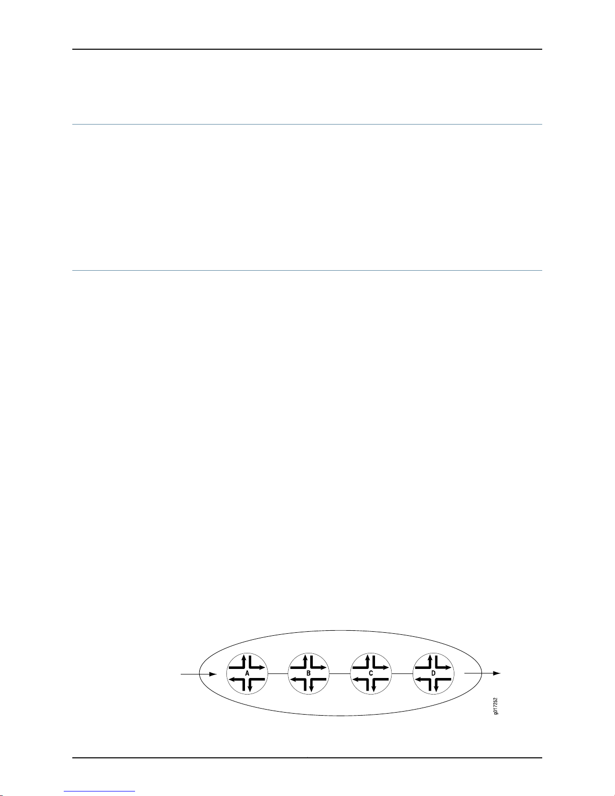
In Figure 1 on page 4, Router A is receiving traffic from a customer network. As each
packet enters, Router A examines the packet’s current CoS settings and classifies the
traffic into one of the groupings defined by the Internet service provider (ISP). This
definition allows Router A to prioritize its resources for servicing the traffic streams it is
receiving. In addition, Router A might alter the CoS settings (forwarding class and loss
priority) of the packets to better match the ISP’s traffic groups. When Router B receives
the packets, it examines the CoS settings, determines the appropriate traffic group, and
processesthe packet according to those settings. It then transmits the packetsto RouterC,
which performs the same actions. Router D also examines the packets and determines
the appropriate group. Because Router D sits at the far end of the network, the ISP might
decide once again to alter the CoS settings of the packets before Router D transmits
them to the neighboring network.
Figure 1: Packet Flow Across the Network
Copyright © 2013, Juniper Networks, Inc.4
Page 19

Junos CoS Components
The Juniper Networks®Junos®operating system (Junos OS) CoS consists of many
components that you can combine and tune to provide the level of services required by
customers.
The Junos OS CoS components include:
•
Code-point aliases—A code-point alias assigns a name to a pattern of code-point bits.
You can use this name instead of the bit pattern when you configure other CoS
components, such as classifiers, drop-profile maps, and rewrite rules.
•
Classifiers—Packet classification refers to the examination of an incoming packet. This
function associates the packet with a particular CoS servicing level. In the Junos OS,
classifiers associate incoming packets with a forwarding class and loss priority and,
based on the associated forwarding class, assign packets to output queues. Two
general types of classifiers are supported:
•
Chapter 1: CoS Overview
Behavior aggregate or CoS value traffic classifiers—A behavior aggregate (BA) is a
method of classification that operates on a packet as it enters the routing device.
The CoS value in the packet header is examined, and this single field determines the
CoS settings applied to the packet. BA classifiers allow you to set the forwarding
class and loss priority of a packet based on the Differentiated Services code point
(DSCP) value, DSCP IPv6 value, IP precedence value, MPLS EXP bits, and IEEE 802.1p
value. The default classifier is based on the IP precedence value.
•
Multifield traffic classifiers—A multifield classifier is a second method for classifying
traffic flows. Unlike a behavior aggregate, a multifield classifier can examine multiple
fields in the packet. Examples of some fields that a multifield classifier can examine
include the source and destination address of the packet as well as the source and
destination port numbers of the packet. With multifield classifiers, you set the
forwarding class and loss priority of a packet based on firewall filter rules.
•
Forwarding classes—The forwarding classes affect the forwarding, scheduling, and
marking policies applied to packets as they transit a routing device. The forwarding
class plus the loss priority define the per-hop behavior. Four categories of forwarding
classes are supported: best effort, assured forwarding, expedited forwarding, and
network control. For Juniper Networks M Series Multiservice Edge Routers, four
forwarding classes are supported. You can configure up to one each of the four types
of forwarding classes. For M120 and M320 Multiservice Edge Routers,Juniper Networks
MX Series 3D Universal Edge Routers, Juniper Networks T Series Core Routers and EX
Series switches, 16 forwarding classes are supported, so you can classify packets more
granularly. For example, you can configure multiple classes of expedited forwarding
(EF) traffic: EF, EF1, and EF2.
•
Loss priorities—Loss priorities allow you to set the priority of dropping a packet. Loss
priority affects the scheduling of a packet without affecting the packet’s relative
ordering. You can use the packet loss priority (PLP) bit as part of a congestion control
strategy. You can use the loss priority setting to identify packets that have experienced
congestion. Typically you mark packets exceeding some service level with a high loss
5Copyright © 2013, Juniper Networks, Inc.
Page 20

Class of Service Overview and Examples for EX9200 Switches
priority. You set loss priority by configuring a classifier or a policer. The loss priority is
used later in the workflow to select one of the drop profiles used by RED.
•
Forwarding policy options—These options allow you to associate forwarding classes
with next hops. Forwarding policy also allows you to create classification overrides,
which assign forwarding classes to sets of prefixes.
•
Transmission scheduling and rate control—These parameters provide you with a variety
of tools to manage traffic flows:
•
Queuing—After a packet is sent to the outgoing interface on a routing device, it is
queued for transmission on the physical media. The amount of time a packet is
queued on the routing device is determined by the availabilityof the outgoing physical
media as well as the amount of traffic using the interface.
•
Schedulers—An individual routing device interface has multiple queues assigned to
store packets. The routing device determines which queue to service based on a
particular method of scheduling. This process often involves a determination of
which type of packet should be transmitted before another.The Junos OS schedulers
allow you to define the priority, bandwidth, delay buffer size, rate control status, and
RED drop profiles to be applied to a particular queue for packet transmission.
Default CoS Settings
•
Fabric schedulers—For M320 and T Series routers only, fabric schedulers allow you
to identify a packet as high or low priority based on its forwarding class, and to
associate schedulers with the fabric priorities.
•
Policers for traffic classes—Policers allow you to limit traffic of a certain class to a
specified bandwidth and burst size. Packets exceeding the policer limits can be
discarded, or can be assigned to a different forwarding class, a different loss priority,
or both. You define policers with filters that can be associated with input or output
interfaces.
•
Rewrite rules—A rewrite rule sets the appropriate CoS bits in the outgoing packet. This
allows the next downstream routing device to classify the packet into the appropriate
service group. Rewriting, or marking, outbound packets is useful when the routing device
is at the border of a network and must alter the CoS values to meet the policies of the
targeted peer.
If you do not configure any CoS settings on your routing device, the software performs
some CoS functions to ensure that user traffic and protocol packets are forwarded with
minimum delay when the network is experiencing congestion. Some default mappings
are automatically applied to each logical interface that you configure. Other default
mappings, such as explicit default classifiers and rewrite rules, are in operation only if
you explicitly associate them with an interface.
You can display default CoS settings by issuing the show class-of-service operational
mode command. This section includes sample output displaying the defaultCoS settings.
The sample output is truncated for brevity.
Copyright © 2013, Juniper Networks, Inc.6
Page 21

show class-of-service
user@host> show class-of-service
Default Forwarding Classes
Forwarding class Queue
best-effort 0
expedited-forwarding 1
assured-forwarding 2
network-control 3
Default Code-Point Aliases
Code point type: dscp
Alias Bit pattern
af11 001010
af12 001100
...
Code point type: dscp-ipv6
...
Code point type: exp
...
Code point type: ieee-802.1
...
Code point type: inet-precedence
...
Chapter 1: CoS Overview
Default Classifiers
Classifier: dscp-default, Code point type: dscp, Index: 7
...
Classifier: dscp-ipv6-default, Code point type: dscp-ipv6, Index: 8
...
Classifier: exp-default, Code point type: exp, Index: 9
...
Classifier: ieee8021p-default, Code point type: ieee-802.1, Index: 10
...
Classifier: ipprec-default, Code point type: inet-precedence, Index: 11
...
Classifier: ipprec-compatibility, Code point type: inet-precedence, Index: 12
...
Default Frame Relay Loss Priority Map
Loss-priority-map: frame-relay-de-default, Code point type: frame-relay-de, Index:
13
Code point Loss priority
0 low
1 high
Default Rewrite Rules
Rewrite rule: dscp-default, Code point type: dscp, Index: 24
Forwarding class Loss priority Code point
best-effort low 000000
7Copyright © 2013, Juniper Networks, Inc.
Page 22

Class of Service Overview and Examples for EX9200 Switches
best-effort high 000000
...
Rewrite rule: dscp-ipv6-default, Code point type: dscp-ipv6, Index: 25
...
Rewrite rule: exp-default, Code point type: exp, Index: 26
...
Rewrite rule: ieee8021p-default, Code point type: ieee-802.1, Index: 27
...
Rewrite rule: ipprec-default, Code point type: inet-precedence, Index: 28
...
Default Drop Profile
Drop profile: <default-drop-profile>, Type: discrete, Index: 1
Fill level Drop probability
100 100
Default Schedulers
Scheduler map: <default>, Index: 2
Scheduler: <default-be>, Forwarding class: best-effort, Index: 17
Transmit rate: 95 percent, Rate Limit: none, Buffer size: 95 percent, Priority:
low
Drop profiles:
Loss priority Protocol Index Name
Low Any 1 <default-drop-profile>
High Any 1 <default-drop-profile>
...
Related
Documentation
Default Forwarding Classes•
• Default Behavior Aggregate Classification Overview
• Default Drop Profile
• Default Schedulers Overview
• Forwarding Classes and Fabric Priority Queues
CoS Applications Overview
You can configureCoS features to meet your application needs. Because the components
are generic, you can use a single CoS configurationsyntaxacross multiple routing devices.
CoS mechanisms are useful for two broad classes of applications. These applications
can be referred to as in the box and across the network.
In-the-box applications use CoS mechanisms to provide special treatment for packets
passing through a single node on the network. You can monitor the incoming traffic on
each interface, using CoS to provide preferred service to some interfaces (that is, to some
customers) while limiting the service provided to other interfaces. You can also filter
outgoing traffic by the packet’s destination, thus providing preferred service to some
destinations.
Copyright © 2013, Juniper Networks, Inc.8
Page 23

Chapter 1: CoS Overview
Across-the-network applications use CoS mechanisms to provide differentiated treatment
to different classes of packets across a set of nodes in a network. In these types of
applications, you typically control the ingress and egress routing devices to a routing
domain and all the routing devices within the domain. You can use the Junos OS CoS
features to modify packets traveling through the domain to indicate the packet’s priority
across the domain.
Specifically, you modify the CoS code points in packet headers, remapping these bits to
values that correspond to levels of service. When all routing devices in the domain are
configured to associate the precedence bits with specific service levels, packets traveling
across the domain receive the same level of service from the ingress point to the egress
point. For CoS to work in this case, the mapping between the precedence bits and service
levels must be identical across all routing devices in the domain.
The Junos OS CoS applications support the following range of mechanisms:
•
Differentiated Services (DiffServ)—The CoS application supports DiffServ, which uses
6-bit IPv4 and IPv6 header type-of-service (ToS) byte settings. The configuration uses
CoS values in the IP and IPv6 ToS fields to determine the forwarding class associated
with each packet.
•
Layer 2 to Layer 3 CoS mapping—The CoS application supports mapping of Layer 2
(IEEE 802.1p) packet headers to routing device forwarding class and loss-priority values.
Layer 2 to Layer 3 CoS mapping involves setting the forwarding class and loss priority
based on information in the Layer 2 header. Output involves mapping the forwarding
class and loss priority to a Layer 2-specific marking. You can mark the Layer 2 and
Layer 3 headers simultaneously.
•
MPLS EXP—Supports configuration of mapping of MPLS experimental (EXP) bit
settings to routing device forwarding classes and vice versa.
•
VPN outer-label marking—Supports setting of outer-label EXP bits, also known as CoS
bits, based on MPLS EXP mapping.
Interface Types That Do Not Support CoS
For original Channelized OC12 PICs, limited CoS functionality is supported. For more
information, contact Juniper Networks customer support.
NOTE: Transmission scheduling is not supported on 8-port, 12-port, and
48-port Fast Ethernet PICs.
You can configure CoS on all interfaces, except the following:
•
cau4—Channelized STM1 IQ interface (configured on the Channelized STM1 IQ PIC).
•
coc1—Channelized OC1 IQ interface (configured on the Channelized OC12 IQ PIC).
•
coc12—Channelized OC12 IQ interface (configured on the Channelized OC12 IQ PIC).
•
cstm-1—Channelized STM1 IQ interface (configured on the Channelized STM1 IQ PIC).
9Copyright © 2013, Juniper Networks, Inc.
Page 24

Class of Service Overview and Examples for EX9200 Switches
•
ct1—Channelized T1 IQ interface (configured on the Channelized DS3 IQ PIC or
Channelized OC12 IQ PIC).
•
ct3—Channelized T3 IQ interface (configured on the Channelized DS3 IQ PIC or
Channelized OC12 IQ PIC).
•
ce1—ChannelizedE1 IQ interface(configuredon the Channelized E1 IQ PIC or Channelized
STM1 IQ PIC).
•
dsc—Discard interface.
•
fxp—Management and internal Ethernet interfaces.
•
lo—Loopback interface. This interface is internally generated.
•
pe—Encapsulates packets destined for the rendezvous point routing device. This
interface is present on the first-hop routing device.
•
pd—De-encapsulates packets at the rendezvous point. This interface is present on the
rendezvous point.
•
vt—Virtual loopback tunnel interface.
NOTE: For channelized interfaces, you can configure CoS on channels, but
not at the controller level. For a complex configuration example, see the
Junos OS Feature Guides.
VPLS and Default CoS Classification
A VPLS routing instance with the no-tunnel-services option configured has a default
classifier applied to the label-switched interface for all VPLS packets coming from the
remote VPLS PE. This default classifier is modifiable only on MX Series routers. On T
Series, when no-tunnel-services option is configured, the custom classifier for VPLS
instances is not supported.
NOTE: With no-tunnel-services configured,custom classifier for VPLS routing
instances on T Series and LMNR based FPC for M320 is not supported. When
a wild card configuration or an explicit routing instances are configured for
VPLS on CoS CLI, the custom classifier binding results in default classifier
binding on Packet Forwarding Engine (PFE).
For example, on routing devices with eight queues (Juniper Networks M120 and M320
Multiservice Edge Routers, MX Series 3D Universal Edge Routers, and T Series Core
Routers),the defaultclassificationapplied to no-tunnel-services VPLS packets are shown
in Table 3 on page 11.
Copyright © 2013, Juniper Networks, Inc.10
Page 25

Table 3: Default VPLS Classifiers
Chapter 1: CoS Overview
Forwarding Class/QueueMPLS Label EXP Bits
0000
1001
2010
3011
4100
5101
6110
7111
NOTE: Forwarding class to queue number mapping is not alwaysone-to-one.
Forwarding classes and queues are only the same when default
forwarding-class-to-queue mapping is in effect. For more information about
configuring forwarding class and queues, see Configuring Forwarding Classes.
On MX Series routers, VPLS filters and policers act on a Layer 2 frame that includes the
media access control (MAC) header (after any VLAN rewrite or other rules are applied),
but does not include the cyclical redundancy check (CRC) field.
NOTE: On MX Series routers, if you apply a counter in a firewall for egress
MPLS or VPLS packets with the EXP bits set to 0, the counter will not tally
these packets.
11Copyright © 2013, Juniper Networks, Inc.
Page 26

Class of Service Overview and Examples for EX9200 Switches
Copyright © 2013, Juniper Networks, Inc.12
Page 27

CHAPTER 2
CoS Input and Output Configuration
•
CoS Inputs and Outputs Overview on page 13
CoS Inputs and Outputs Overview
Some CoS components map one set of values to another set of values. Each mapping
contains one or more inputs and one or more outputs.
Some CoS components map one set of values to another set of values. Each mapping
contains one or more inputs and one or more outputs. When you configure a mapping,
you set the outputs for a given set of inputs, as shown in Table 4 on page 13.
Table 4: CoS Mappings—Inputs and Outputs
CommentsOutputsInputsCoS Mappings
code-pointsclassifiers
Related
Documentation
forwarding-class
loss-priority
code-pointsloss-priorityrewrite-rules
• Default Behavior Aggregate Classification Overview
• Configuring Drop Profile Maps for Schedulers
• Applying Default Rewrite Rules
• CoS Inputs and Outputs Examples
The map sets the forwardingclassand PLP for a specific set of code
points.
The map sets the drop profile for a specific PLP and protocol type.drop-profileloss-priority protocoldrop-profile-map
The map sets the code points for a specific forwarding class and
PLP.
13Copyright © 2013, Juniper Networks, Inc.
Page 28

Class of Service Overview and Examples for EX9200 Switches
Copyright © 2013, Juniper Networks, Inc.14
Page 29

CHAPTER 3
Packet Flow Through the CoS Process
•
Packet Flow Through the CoS Process Overview on page 15
Packet Flow Through the CoS Process Overview
Perhaps the best way to understand Junos CoS is to examine how a packet is treated on
its way through the CoS process. This topic includes a description of each step and figures
illustrating the process.
The following steps describe the CoS process:
1. A logical interface has one or more classifiers of different types applied to it (at the
[edit class-of-service interfaces] hierarchy level). The types of classifiers are based
on which part of the incoming packet the classifier examines (for example, EXP bits,
IEEE 802.1p bits, or DSCP bits). You can use a translation table to rewrite the values
of these bits on ingress.
NOTE: You can only rewrite the values of these bits on ingress on the
Juniper Networks M40e, M120, M320 Multiservice Edge Routers, and T
Series Core Routers with IQE PICs. For more information about rewriting
the values of these bits on ingress, see Configuring ToS Translation Tables.
2. The classifier assigns the packet to a forwarding class and a loss priority (at the [edit
class-of-service classifiers] hierarchy level).
3. Each forwarding class is assigned to a queue (at the [edit class-of-service
forwarding-classes] hierarchy level).
4. Input (and output) policers meter traffic and might change the forwarding class and
loss priority if a traffic flow exceeds its service level.
5. The physical or logical interface has a scheduler map applied to it (at the [edit
class-of-service interfaces] hierarchy level).
At the [edit class-of-service interfaces] hierarchy level, the scheduler-map and
rewrite-rules statements affect the outgoing packets, and the classifiers statement
affects the incoming packets.
15Copyright © 2013, Juniper Networks, Inc.
Page 30

g017213
Behavior
Aggregate
Classifier
Multifield
Classifier
Input Policer
Forwarding
Policy
Options
Forwarding Class
and Loss Priority
Rewrite
Marker
Scheduler/Shaper/RED
(all platforms)
Adaptive Shaper/Virtual Channels
(J Series only)
Output Policer
Fabric Scheduler
(M320 and
T Series only)
Class of Service Overview and Examples for EX9200 Switches
6. The scheduler defines how traffic is treated in the output queue—for example, the
transmit rate, buffer size, priority, and drop profile (at the [edit class-of-service
schedulers] hierarchy level).
7. The scheduler map assigns a scheduler to each forwarding class (at the [edit
class-of-service scheduler-maps] hierarchy level).
8. The drop-profile defines how aggressively to drop packets that are using a particular
scheduler (at the [edit class-of-service drop-profiles] hierarchy level).
9. The rewrite rule takes effect as the packet leaves a logical interface that has a rewrite
rule configured (at the [edit class-of-service rewrite-rules] hierarchy level).The rewrite
rule writes information to the packet (for example, EXP or DSCP bits) according to
the forwarding class and loss priority of the packet.
Figure 2 on page 16 and Figure 3 on page 16 show the components of the Junos CoS
features, illustrating the sequence in which they interact.
Figure 2: CoS Classifier, Queues, and Scheduler
Figure 3: Packet Flow Through CoS Configurable Components
Copyright © 2013, Juniper Networks, Inc.16
Page 31

Chapter 3: Packet Flow Through the CoS Process
Each outer box in Figure 3 on page 16 represents a process component. The components
in the upper row apply to inbound packets, and the components in the lower row apply
to outbound packets. The arrows with the solid lines point in the direction of packet flow.
The middle box (forwarding class and loss priority) represents two data values that can
either be inputs to or outputs of the process components. The arrows with the dotted
lines indicate inputs and outputs (or settings and actions based on settings). For example,
the multifield classifier sets the forwarding class and loss priority of incoming packets.
This means that the forwarding class and loss priority are outputs of the classifier; thus,
the arrow points away from the classifier. The scheduler receives the forwarding class
and loss priority settings, and queues the outgoing packet based on those settings. This
means that the forwarding class and loss priority are inputs to the scheduler; thus, the
arrow points to the scheduler.
Typically, only a combination of some components (not all) is used to define a CoS
service offering.
Related
Documentation
• Packet Flow Through the CoS Process Configuration Example
17Copyright © 2013, Juniper Networks, Inc.
Page 32

Class of Service Overview and Examples for EX9200 Switches
Copyright © 2013, Juniper Networks, Inc.18
Page 33

PART 2
Configuration
•
Configuration Statements on page 21
19Copyright © 2013, Juniper Networks, Inc.
Page 34

Class of Service Overview and Examples for EX9200 Switches
Copyright © 2013, Juniper Networks, Inc.20
Page 35

CHAPTER 4
Configuration Statements
•
[edit chassis] Hierarchy Level on page 21
•
[edit class-of-service] Hierarchy Level on page 29
•
[edit firewall] Hierarchy Level on page 33
•
[edit interfaces] Hierarchy Level on page 46
[edit chassis] Hierarchy Level
chassis {
aggregated-devices {
ethernet {
device-count number;
lacp {
link-protection {
non-revertive;
}
system-priority;
}
}
sonet {
device-count number;
}
maximum-links maximum-links-limit;
}
alarm {
ds1 {
ais (ignore | red | yellow);
ylw (ignore | red | yellow);
}
ethernet {
link-down (ignore | red | yellow);
}
integrated-services {
failure (ignore | red | yellow);
}
management-ethernet {
link-down (ignore | red | yellow);
}
relay
input {
port port-number {
21Copyright © 2013, Juniper Networks, Inc.
Page 36

Class of Service Overview and Examples for EX9200 Switches
mode (close | open);
trigger (ignore | red | yellow;
}
}
output{
port port-number {
input-relay input-relay;
mode (close | open);
temperature;
}
}
serial {
cts-absent (ignore | red | yellow);
dcd-absent (ignore | red | yellow);
dsr-absent (ignore | red | yellow);
loss-of-rx-clock (ignore | red | yellow);
loss-of-tx-clock (ignore | red | yellow);
tm-absent (ignore | red | yellow);
}
services {
hw-down (ignore | red | yellow);
linkdown (ignore | red | yellow);
pic-hold-reset (ignore | red | yellow);
pic-reset (ignore | red | yellow);
rx-errors (ignore | red | yellow);
sw-down (ignore | red | yellow);
tx-errors (ignore | red | yellow);
}
sonet {
(ais-l | ais-p | ber-sd | ber-sf | locd | lol | lop-p | los | pll | plm-p | rfi-l | rfl-p | uneq-p)
(ignore | red | yellow);
}
t3 {
(ais | exz | ferf | idle | lcv | lof | los | pll | ylw) (ignore | red | yellow);
}
}
cluster {
control-link-recovery;
control-ports {
fpc slot-number port port-number;
}
heartbeat-interval milliseconds;
heartbeat-threshold number;
redundancy-group {
... the redundancy-group subhierarchy appears at the end of the [edit chassis cluster]
hierarchy ...
}
reth-count number;
traceoptions {
file <filename > <files number> <match regular-expression> <size maximum-file-size>
<world-readable | no-world-readable>;
flag flag;
level severity;
no-remote-trace;
}
redundancy-group group-number {
Copyright © 2013, Juniper Networks, Inc.22
Page 37

Chapter 4: Configuration Statements
gratuitous-arp-count number;
hold-down-interval seconds;
interface-monitor {
interface-name weight number;
}
ip-monitoring {
family {
inet {
ipv4-address {
interfacerethindex.logical-unit-numbersecondary-ip-address ipv4-address;
weight number;
}
}
}
global-threshold number;
global-weight number;
retry-count count;
retry-interval interval;
}
node node-number priority priority-number;
preempt;
}
config-button {
no-clear;
no-rescue;
}
container-devices {
device-count number;
}
craft-lockout;
disable-power-management;
disk-partition partition-name (/config |/var) {
level (full | high) {
free-space threshold-value (mb | percent);
}
}
enhanced-policer;
extended-statistics;
fabric {
degraded {
action-fpc-restart-disable;
degraded-fabric-detection-enable
degraded-fpc-bad-plane-threshold number-bad-planes;
}
redundancy-mode (increased-bandwidth | redundant);
}
filter;
fpc slot-number {
... the fpc subhierarchy appears after the main [edit chassis] hierarchy ...
}
fpc-feb-connectivity {
fpc slot-number feb (slot-number | none);
}
fpc-resync;
fru-poweron-sequence sequence;
lcc index {
23Copyright © 2013, Juniper Networks, Inc.
Page 38

Class of Service Overview and Examples for EX9200 Switches
... the lcc subhierarchy appears after the main [edit chassis] hierarchy ...
}
maximum-ecmp value;
memory-enhanced {
filter;
route;
vpn-label;
}
network-services (ethernet | enhanced-ethernet | ip | enhanced-ip);
(packet-scheduling | no-packet-scheduling);
pem {
minimum number;
}
policer-drop-probability-low;
ppp-subscriber-services (disable | enable);
redundancy {
cfeb slot (always | preferred);
failover {
on-disk-failure;
on-loss-of-keepalives;
}
feb {
redundancy-group group-name {
description description;
feb slot-number <backup | primary>;
no-auto-failover;
}
}
graceful-switchover;
keepalive-time seconds;
routing-engine slot-number (backup | disabled | master);
sfm slot-number (always | preferred);
ssb slot-number (always | preferred);
}
route-memory-enhanced;
route-localization {
inet (chassis);
inet6;
}
routing-engine {
bios {
no-auto-upgrade;
}
on-disk-failure disk-failure-action (halt | reboot);
}
sfm slot-number {
power off;
}
sib {
minimum number;
}
(source-route | no-source-route);
state [
cb-upgrade [on | off];
}
synchronization { # for M Series and T Series routers
Copyright © 2013, Juniper Networks, Inc.24
Page 39

Chapter 4: Configuration Statements
primary (external-a | external-b);
secondary (external-a | external-b);
signal-type (e1 | t1);
switching-mode (non-revertive | revertive);
transmitter-enable;
validation-interval seconds;
y-cable-line-termination;
}
synchronization { # for MX80 and MX240 routers
clock-mode (auto-select | free-run);
esmc-transmit {
interfaces (all | interface-name);
}
hold-interval {
configuration-change seconds;
restart seconds;
switchover seconds;
}
network-option (option-1 | option-2);
quality-mode-enable;
selection-mode (configured-quality|received-quality);
source {
(external-a | external-b) {
priority number;
quality-level (prc | prs |sec | smc | ssu-a | ssu-b | st2 | st3 | st3e | st4 | stu | tnc);
request (force-switch | lockout);
}
interfaces interface-name {
priority number;
quality-level (prc | prs |sec | smc | ssu-a | ssu-b | st2 | st3 | st3e | st4 | stu | tnc);
request (force-switch | lockout);
wait-to-restore minutes;
}
}
switchover-mode (revertive | non-revertive);
}
synchronization { # for ACX Series routers
clock-mode (auto-select | free-run);
esmc-transmit {
interfaces (all | interface-name);
}
hold-interval {
configuration-change seconds;
restart seconds;
switchover seconds;
}
network-option (option-1 | option-2);
quality-mode-enable;
selection-mode (configured-quality | received-quality);
source {
(bits | gps) {
priority number;
quality-level (prc | prs |sec | smc | ssu-a | ssu-b | st2 | st3 | st3e | st4 | stu | tnc);
request (force-switch | lockout);
}
interfaces interface-name {
25Copyright © 2013, Juniper Networks, Inc.
Page 40

Class of Service Overview and Examples for EX9200 Switches
priority number;
quality-level (prc | prs |sec | smc | ssu-a | ssu-b | st2 | st3 | st3e | st4 | stu | tnc);
request (force-switch | lockout);
wait-to-restore minutes;
}
}
switchover-mode(non-revertive | revertive);
}
system-domains {
protected-system-domains psdnumerical-index {
control-plane-bandwidth-percent percent;
control-slot-numbers [ slot-numbers ];
control-system-id control-system-id;
description description;
fpcs [ slot-numbers ];
}
root-domain-id root-domain-id;
}
vrf-mtu-check;
}
chassis {
fpc slot-number {
number-of-ports active-ports;
offline;
pic slot-number {
... the pic subhierarchy appears after the main [edit chassis fpc slot-number] hierarchy
...
}
port-mirror-instance port-mirror-instance-name;
power (off | on);
sampling-instance instance-name;
}
fpc slot-number {
pic slot-number {
adaptive-services {
service-package(layer-2 | layer-3 | ...the following extension-providersubhierarchy
...);
extension-provider {
control-cores number;
data-cores number;
data-flow-affinity {
hash-key (layer-3 | layer-4);
}
channelization;
forwarding-db-size megabytes;
object-cache-size megabytes;
package package-name;
policy-db-size megabytes;
syslog {
facility {
severity;
destination (pic-console | routing-engine);
}
}
Copyright © 2013, Juniper Networks, Inc.26
Page 41

wired-process-mem-size megabytes;
}
}
aggregated-devices {
ima {
device-count number;
}
}
aggregate-ports;
atm-cell-relay-accumulation;
atm-l2circuit-mode (aal5 | cell | trunk trunk);
ce1 {
e1 port-number {
channel-group group-number timeslots slot-number;
}
}
ct3 {
port port-number {
t1 link-number {
channel-group group-number timeslots slot-number;
}
}
}
ethernet {
pic-mode (enhanced-switching | routing | switching);
}
fibre-channel {
port port-number;
port-range port-range-low port-range-high
}
egress-policer-overhead bytes;
forwarding-mode {
sa-multicast;
vlan-steering {
vlan-rule (high-low | odd-even);
}
}
framing (e1 | e3 | sdh | sonet | t1 | t3);
idle-cell-format {
itu-t;
payload-pattern payload-pattern-byte;
}
ingress-policer-overhead bytes;
inline-services {
bandwidth (1g | 10g);
}
linerate-mode;
max-queues-per-interface (4 | 8);
mlfr-uni-nni-bundles number;
no-concatenate;
no-multi-rate;
port port-number {
framing (e1 | e3 | sdh | sonet | t1 | t3);
forwarding-mode {
sa-multicast;
}
Chapter 4: Configuration Statements
27Copyright © 2013, Juniper Networks, Inc.
Page 42

Class of Service Overview and Examples for EX9200 Switches
speed ( oc3-stm1 | oc12-stm4 | oc48-stm16);
}
port-mirror-instance port-mirror-instance-name;
q-pic-large-buffer {
(large-scale | small-scale);
}
red-buffer-occupancy {
weighted-averaged <instant-usage-weight-exponent weight-value>;
}
shdsl {
pic-mode (1-port-atm | 2-port-atm);
}
sparse-dlcis;
traffic-manager {
egress-shaping-overhead number;
ingress-shaping-overhead number;
mode {
egress-only;
ingress-and-egress;
session-shaping;
}
}
tunnel-queuing;
tunnel-services {
bandwidth (1g | 10g | 20g | 40g);
tunnel-only;
}
vtmapping (itu-t | klm);
}
}
}
chassis {
lcc index {
fpc slot-number {
... the fpc subhierarchy appears after the main [edit chassis lcc index] hierarchy ...
}
offline;
online-expected;
}
}
lcc index {
fpc slot-number {
pic slot-number {
... the pic subhierarchy appears after the main [edit chassis lcc index fpc slot-number]
hierarchy ...
}
power (off | on);
sampling-instance instance-name;
}
fpc slot-number {
pic slot-number {
aggregate-ports;
atm-cell-relay-accumulation;
Copyright © 2013, Juniper Networks, Inc.28
Page 43

atm-l2circuit-mode (aal5 | cell | trunk trunk);
framing (e1 | e3 | sdh | sonet | t1 | t3);
idle-cell-format {
itu-t;
payload-pattern payload-pattern-byte;
}
linerate-mode;
max-queues-per-interface (4 | 8);
no-concatenate;
no-mcast-replication;
no-pre-classifier;
port port-number {
framing (e1 | e3 | sdh | sonet | t1 | t3);
}
q-pic-large-buffer {
(large-scale | small-scale);
}
red-buffer-occupancy {
weighted-averaged <instant-usage-weight-exponent weight-value>;
}
shdsl {
pic-mode (1-port-atm | 2-port-atm);
}
traffic-manager {
egress-shaping-overhead bytes;
ingress-shaping-overhead bytes;
mode {
egress-only;
ingress-and-egress;
}
}
}
}
}
Chapter 4: Configuration Statements
Related
Notational Conventions Used in Junos OS Configuration Hierarchies•
Documentation
[edit class-of-service] Hierarchy Level
class-of-service {
classifiers {
type classifier-name {
forwarding-class class-name {
loss-priority (high | low | medium-high | medium-low) code-points [ aliases bits ];
}
import (classifier-name | default);
}
}
code-point-aliases {
(dscp | dscp-ipv6 | exp | ieee-802.1 | ieee-802.1ad | inet-precedence) {
alias-name bits;
}
}
drop-profiles {
29Copyright © 2013, Juniper Networks, Inc.
Page 44

Class of Service Overview and Examples for EX9200 Switches
profile-name {
fill-level percentage drop-probability percentage;
interpolate {
drop-probability value;
fill-level value;
}
}
}
fabric {
scheduler-map {
priority (high | low) scheduler scheduler-name;
}
}
forwarding-class-map {
map-name {
class class-name queue-num queue-number <restricted-queue queue-number>;
}
}
forwarding-classes {
class class-name policing-priority (normal | premium) queue-num queue-number
priority (high | low);
queue queue-number class-name policing-priority (normal | premium) priority (high |
low);
}
forwarding-policy {
class class-name {
classification-override {
forwarding-class class-name;
}
}
next-hop-map map-name {
forwarding-class class-name {
discard;
lsp-next-hop [ lsp-regular-expressions ];
next-hop [ next-hop-names ];
non-lsp-next-hop;
}
}
}
fragmentation-maps {
map-name {
forwarding-class class-name {
drop-timeout milliseconds;
fragment-threshold bytes;
multilink-class number;
no-fragmentation;
}
}
}
host-outbound-traffic {
dscp-code-point value;
forwarding-class class-name;
ieee-802.1 {
default value;
rewrite-rules;
}
Copyright © 2013, Juniper Networks, Inc.30
Page 45

Chapter 4: Configuration Statements
tcp {
raise-internet-control-priority;
}
}
interfaces {
... the interfaces subhierarchy appears after the main [edit class-of-service] hierarchy
...
}
}
restricted-queues {
forwarding-class class-name queue-number;
}
rewrite-rules {
(dscp | dscp-ipv6 | exp |frame-relay-de | ieee-802.1 | ieee-802.1ad | inet-precedence)
rewrite-rule {
forwarding-class class-name {
loss-priority level code-point (alias | bits);
}
import (rewrite-rule | default);
}
}
routing-instances routing-instance-name {
classifiers {
dscp (classifier-name | default);
dscp-ipv6 (classifier-name | default);
exp (classifier-name | default);
ieee-208.1 (classifier-name | default | encapsulated | vlan-tag (inner | outer));
}
}
scheduler-maps {
map-name {
forwarding-class class-name scheduler scheduler-name;
}
}
schedulers {
scheduler-name {
adjust-minimum value;
adjust-percent value;
buffer-size (exact | percent percentage | remainder);
drop-profile-map loss-priority (any | high | low | medium-high | medium-low)
protocol any;
excess-priority (high | low | medium-high | medium-low);
excess-rate (percent percentage | proportion proportion);
priority (high | low | medium-high | medium-low | strict-high);
shaping-rate (bps | percent percentage | burst-size size);
transmit-rate (bps | percent percentage | remainder) <exact | rate-limit>;
}
}
traceoptions {
file <files number> <match regular-expression> <size maximum-file-size>
<world-readable | no-world-readable>;
flag flag;
no-remote-trace;
}
traffic-control-profiles {
profile-name {
31Copyright © 2013, Juniper Networks, Inc.
Page 46

Class of Service Overview and Examples for EX9200 Switches
adjust-minimum rate;
delay-buffer-rate (bps | cps cps | percent percentage);
excess-rate (percent percentage | proportion value);
guaranteed-rate (bps | percent percentage) <burst-size bytes>;
overhead-accounting (frame-mode | cell-mode) <bytes byte-value>;
scheduler-map map-name;
shaping-rate (bps | percent percentage) <burst-size bytes>;
}
}
tri-color;
}
class-of-service {
interfaces {
interface-name {
excess-bandwith-share (equal | proportional value);
input-excess-bandwith-share (equal | proportional value);
input-scheduler-map map-name;
input-shaping-rate bps;
input-traffic-control-profile profile-name;
output-forwarding-class-map map-name;
output-traffic-control-profile profile-name;
scheduler-map map-name;
scheduler-map-chassis (map-name | derived);
shaping-rate bps;
unit (logical-unit-number | *){
classifiers {
dscp (classifier-name | default) {
family [ inet mpls ];
}
dscp-ipv6 (classifier-name | default) {
family [ inet mpls ];
}
exp (classifier-name | default);
ieee-208.1 (classifier-name | default) <vlan-tag (inner | outer)>;
ieee-208.1ad (classifier-name | default);
inet-precedence (classifier-name | default);
}
forwarding-class class-name;
input-scheduler-map map-name;
input-shaping-rate bps;
input-traffic-control-profile profile-name shared-instance instance-name;
loss-priority-maps {
(map-name | default);
}
loss-priority-rewrites {
(map-name | default);
}
output-forwarding-class-map map-name;
output-traffic-control-profile profile-name shared-instance instance-name;
rewrite-rules {
dscp (rule-name | default) <protocol mpls>;
dscp-ipv6 (rule-name | default);
exp (rule-name | default) <protocol [ mpls-any | mpls-inet-both |
mpls-inet-both-non-vpn ]>;
exp-push-push-push default;
Copyright © 2013, Juniper Networks, Inc.32
Page 47

exp-swap-push-push default;
ieee-802.1 (rewrite-name | default) <vlan-tag (outer | outer-and-inner)>;
ieee-802.1ad (rewrite-name | default) <vlan-tag (outer | outer-and-inner)>;
inet-precedence (rewrite-name | default) <protocol mpls>;
}
scheduler-map map-name;
shaping-rate bps;
translation-table (to-dscp-from-dscp | to-dscp-ipv6-from-dscp-ipv6 |
to-exp-from-exp | to-inet-precedence-from-inet-precedence) table-name;
}
}
interface-set interface-set-name {
excess-bandwith-share (equal | proportional value);
input-excess-bandwith-share (equal | proportional value);
input-traffic-control-profile profile-name;
input-traffic-control-profile-remaining profile-name;
internal-node;
output-traffic-control-profile profile-name;
output-traffic-control-profile-remaining profile-name;
}
}
}
Chapter 4: Configuration Statements
Related
Notational Conventions Used in Junos OS Configuration Hierarchies•
Documentation
[edit firewall] Hierarchy Level
Several statements in the [edit firewall] hierarchy are valid at numerous locations within
the hierarchy. To make the complete hierarchy easier to read, the repeated statements
are listed in the following sections, which are referenced at the appropriate locations in
“Complete [edit firewall] Hierarchy” on page 38.
•
Common Firewall Actions on page 33
•
Common IP Firewall Actions on page 34
•
Common IPv4 Firewall Actions on page 34
•
Common IP Firewall Match Conditions on page 35
•
Common IPv4 Firewall Match Conditions on page 36
•
Common Layer 2 Firewall Match Conditions on page 36
•
Complete [edit firewall] Hierarchy on page 38
Common Firewall Actions
This section lists statements that are valid at the following hierarchy levels, and is
referenced at those levels in “Complete [edit firewall] Hierarchy” on page 38 instead of
the statements being repeated.
•
[edit firewall family (any | ccc | ethernet-switching | inet | inet6 | mpls | vpls) filter
filter-name term term-name then]
•
[edit firewall filter filter-name term term-name then]
33Copyright © 2013, Juniper Networks, Inc.
Page 48

Class of Service Overview and Examples for EX9200 Switches
The common firewall actions are as follows:
count counter-name;
forwarding-class class-name;
loss-priority (high | low | medium-high | medium-low);
next term;
policer policer-name;
three-color-policer policer-name {
(single-rate single-rate-policer-name | two-rate two-rate-policer-name);
}
Common IP Firewall Actions
This section lists statements that are valid at the following hierarchy levels, and is
referenced at those levels in “Complete [edit firewall] Hierarchy” on page 38 instead of
the statements being repeated.
•
[edit firewall family inet filter filter-name term term-name then]
•
[edit firewall family inet6 filter filter-name term term-name then]
•
[edit firewall filter filter-name term term-name then]
The common IP firewall actions are as follows:
log;
logical-system logical-system-name <routing-instance routing-instance-name>
<topology topology-name>;
port-mirror;
port-mirror-instance instance-name;
routing-instance routing-instance-name> <topology topology-name>;
sample;
service-filter-hit;
syslog;
topology topology-name;
Common IPv4 Firewall Actions
This section lists statements that are valid at the following hierarchy levels, and is
referenced at those levels in “Complete [edit firewall] Hierarchy” on page 38 instead of
the statements being repeated.
•
[edit firewall family inet filter filter-name term term-name then]
•
[edit firewall filter filter-name term term-name then]
The common IP version 4 (IPv4) firewall actions are as follows:
(accept | discard <accounting collector-name> | reject <administratively-prohibited |
bad-host-tos | bad-network-tos | fragmentation-needed | host-prohibited |
host-unknown | host-unreachable | network-prohibited | network-unknown |
network-unreachable | port-unreachable | precedence-cutoff | precedence-violation |
protocol-unreachable | source-host-isolated | source-route-failed | tcp-reset>);
ipsec-sa sa-name;
load-balance sa-name;
next-hop-group group-name;
prefix-action action-name;
Copyright © 2013, Juniper Networks, Inc.34
Page 49

Common IP Firewall Match Conditions
This section lists statements that are valid at the following hierarchy levels, and is
referenced at those levels in “Complete [edit firewall] Hierarchy” on page 38 instead of
the statements being repeated.
•
[edit firewall family inet dialer-filter filter-name term term-name from] (with the
exceptions noted at this level in “Complete [edit firewall] Hierarchy” on page 38)
•
[edit firewall family inet filter filter-name term term-name from]
•
[edit firewall family inet6 dialer-filter filter-name term term-name from] (with the
exceptions noted at this level in “Complete [edit firewall] Hierarchy” on page 38)
•
[edit firewall family inet6 filter filter-name term term-name from]
•
[edit firewall filter filter-name term term-name from]
The common IP firewall match conditions are as follows:
address {
ip-prefix</prefix-length> <except>;
}
destination-address {
ip-prefix</prefix-length> <except>;
}
destination-class [ class-names ] | destination-class-except [ class-names ]);
(destination-port [ port-names ] | destination-port-except [ port-names ]);
destination-prefix-list {
list-name <except>;
}
(forwarding-class [ class-names ] | forwarding-class-except [ class-names ]);
(icmp-code [ codes ] | icmp-code-except [ codes ]);
(icmp-type [ types ] | icmp-type-except [ types ]);
interface interface-name;
(interface-group [ group-names ] | interface-group-except [ group-names ]);
interface-set set-name;
(loss-priority [ priorities ] | loss-priority-except [ priorities ]);
(packet-length [ values ] | packet-length-except [ values ]);
(port [ port-names ] | port-except [ port-names ]);
prefix-list {
list-name <except>;
}
service-filter-hit;
source-address {
ip-prefix</prefix-length> <except>;
}
(source-class [ class-names ] | source-class-except [ class-names ]);
(source-port [ port-names ] | source-port-except [ port-names ]);
source-prefix-list {
list-name <except>;
}
tcp-established;
tcp-flags flag;
tcp-initial;
Chapter 4: Configuration Statements
35Copyright © 2013, Juniper Networks, Inc.
Page 50

Class of Service Overview and Examples for EX9200 Switches
Common IPv4 Firewall Match Conditions
This section lists statements that are valid at the following hierarchy levels, and is
referenced at those levels in “Complete [edit firewall] Hierarchy” on page 38 instead of
the statements being repeated.
•
[edit firewall family inet dialer-filter filter-name term term-name from] (with the
exceptions noted at this level in “Complete [edit firewall] Hierarchy” on page 38)
•
[edit firewall family inet filter filter-name term term-name from]
•
[edit firewall filter filter-name term term-name from]
The common IPv4 firewall match conditions are as follows:
(ah-spi [ values ] | ah-spi-except [ values ]);
(dscp [ code-point-values ] | dscp-except [ code-point-values ]);
(esp-spi [ values ] | esp-spi-except [ values ]);
first-fragment;
fragment-flags flag;
(fragment-offset [ offsets ] | fragment-offset-except [ offsets ]);
(ip-options [ option-names ] | ip-options-except [ option-names ]);
is-fragment;
(precedence [ precedence-names ] | precedence-except [ precedence-names ]);
(protocol [ protocol-names ] | protocol-except [ protocol-names ]);
(ttl [ ttl-values ] | ttl-except [ ttl-values ]);
Common Layer 2 Firewall Match Conditions
This section lists statements that are valid at the following hierarchy levels, and is
referenced at those levels in “Complete [edit firewall] Hierarchy” on page 38 instead of
the statements being repeated.
•
[edit firewall family ethernet-switching filter filter-name term term-name from]
•
[edit firewall family vpls filter filter-name term term-name from]
The common Layer 2 firewall match conditions are as follows:
destination-mac-address {
mac-address <except>;
}
(destination-port [ port-names ] | destination-port-except [ port-names ]);
(dscp [ code-point-values ] | dscp-except [ code-point-values ]);
(ether-type [ protocol-types ] | ether-type-except [ protocol-types ]);
(forwarding-class [ class-names ] | forwarding-class-except [ class-names ]);
(icmp-code [ codes ] | icmp-code-except [ codes ]);
(icmp-type [ types ] | icmp-type-except [ types ]);
(interface-group [ group-names ] | interface-group-except [ group-names ]);
ip-address {
ip-prefix</prefix-length> <except>;
}
ip-destination-address {
ip-prefix</prefix-length> <except>;
}
Copyright © 2013, Juniper Networks, Inc.36
Page 51

Chapter 4: Configuration Statements
(ip-precedence [ precedence-names ] | ip-precedence-except [ precedence-names ]);
(ip-protocol [ protocol-names ] | ip-protocol-except [ protocol-names ]);
ip-source-address ip-prefix</prefix-length>;
(learn-vlan-1p-priority [ priorities ] | learn-vlan-1p-priority [ priorities ]);
(learn-vlan-id [ vlan-ids ] | learn-vlan-id-except [ vlan-ids ]);
(loss-priority [ priorities ] | loss-priority-except [ priorities ]);
(port [ port-names ] | port-except [ port-names ]);
source-mac-address {
mac-address <except>;
}
(source-port [ port-names ] | source-port-except [ port-names ]);
tcp-flags flag;
(traffic-type [ broadcast known-unicast multicast unknown-unicast ] |
traffic-type-except [ broadcast known-unicast multicast unknown-unicast ]);
(user-vlan-1p-priority [ priorities ] | user-vlan-1p-priority [ priorities ]);
(user-vlan-id [ vlan-ids ] | user-vlan-id-except [ vlan-ids ]);
(vlan-ether-type [ protocol-types ] | vlan-ether-type-except [ protocol-types ]);
37Copyright © 2013, Juniper Networks, Inc.
Page 52

Class of Service Overview and Examples for EX9200 Switches
Complete [edit firewall] Hierarchy
firewall {
family (any | ccc | ethernet-switching | inet | inet6 | mpls | vpls) {
... the family subhierarchies appear after the main [edit firewall] hierarchy ...
}
filter filter-name {
accounting-profile [ profile-names ];
enhanced-mode;
interface-shared-with;
interface-specific;
physical-interface-policer;
term term-name {
filter filter-name;
from {
... statements in Common IP Firewall Match Conditions on page 35 AND
statements in Common IPv4 Firewall Match Conditions on page 36 ...
}
then {
... statements in Common Firewall Actions on page 33 AND
statements in Common IP Firewall Actions on page 34 AND
statements in Common IPv4 Firewall Actions on page 34 ...
}
}
}
hierarchical-policer policer-name {
aggregate {
if-exceeding {
bandwidth-limit bps;
burst-size-limit bytes;
}
then {
discard;
forwarding-class class-name;
loss-priority (high | low | medium-high | medium-low);
}
}
logical-interface-policer;
physical-interface-policer;
premium {
if-exceeding {
bandwidth-limit bps;
burst-size-limit bytes;
}
then {
discard;
}
}
}
shared-bandwidth-policer;
interface-set interface-set-name {
interface-name;
}
load-balance-group group-name {
next-hop-group [ group-names ];
Copyright © 2013, Juniper Networks, Inc.38
Page 53

}
policer policer-name {
filter-specific;
if-exceeding {
(bandwidth-limit bps | bandwidth-percent percentage);
burst-size-limit bytes;
}
logical-bandwidth-policer;
logical-interface-policer;
physical-interface-policer;
then {
discard;
forwarding-class class-name;
loss-priority (high | low | medium-high | medium-low);
}
}
three-color-policer policer-name {
action {
loss-priority high then discard;
}
filter-specific;
logical-interface-policer;
physical-interface-policer;
shared-bandwidth-policer;
single-rate {
(color-aware | color-blind);
committed-burst-size bytes;
committed-information-rate bps;
excess-burst-size bytes;
}
two-rate {
(color-aware | color-blind);
committed-burst-size bytes;
committed-information-rate bps;
peak-burst-size bytes;
peak-information-rate bps;
}
}
}
Chapter 4: Configuration Statements
firewall {
family any {
filter filter-name {
interface-shared;
term term-name {
from {
(forwarding-class [ class-names ] | forwarding-class-except [ class-names ]);
interface interface-name;
interface-set set-name;
(loss-priority [ priorities ] | loss-priority-except [ priorities ]);
(packet-length [ values ] | packet-length-except [ values ]);
}
then {
... statements in Common Firewall Actions on page 33 PLUS ...
(accept | discard);
}
39Copyright © 2013, Juniper Networks, Inc.
Page 54

Class of Service Overview and Examples for EX9200 Switches
}
}
}
}
firewall {
family ccc {
filter filter-name {
accounting-profile [ profile-names ];
physical-interface-filter;
interface-specific;
term term-name {
filter filter-name;
from {
(forwarding-class [ class-names ] | forwarding-class-except [ class-names ]);
(interface-group [ group-names ] | interface-group-except [ group-names ]);
(learn-vlan-1p-priority [ priorities ] | learn-vlan-1p-priority [ priorities ]);
(loss-priority [ priorities ] | loss-priority-except [ priorities ]);
(user-vlan-1p-priority [ priorities ] | user-vlan-1p-priority [ priorities ]);
}
then {
... statements in Common Firewall Actions on page 33 PLUS ...
(accept | discard);
port-mirror-instance instance-name;
}
}
}
}
}
firewall {
family ethernet-switching {
filter filter-name {
interface-specific;
term term-name {
from {
destination-address {
ip-prefix</prefix-length>;
}
destination-mac-address {
mac-address;
}
destination-port [ port-names ];
destination-prefix-list {
list-name;
}
dot1q-tag [ tag-values ];
dot1q-user-priority [ priority-values ];
dscp [ code-point-values ];
ether-type [ protocol-names ];
fragment-flags flag;
icmp-code [ codes ];
icmp-type [ types ];
interface interface-name;
is-fragment;
Copyright © 2013, Juniper Networks, Inc.40
Page 55

Chapter 4: Configuration Statements
precedence [ precedence-names ];
protocol [ protocol-names ];
source-address {
ip-prefix</prefix-length>;
}
source-mac-address {
mac-address;
}
source-port [ port-names ];
source-prefix-list {
list-name;
}
tcp-established;
tcp-flags flag;
tcp-initial;
vlan [ vlan-names ];
}
then {
(accept | discard);
analyzer analyzer-name;
count counter-name;
forwarding-class class-name;
interface interface-name;
log;
loss-priority (high | low);
policer policer-name;
syslog;
vlan vlan-name;
}
}
}
}
}
firewall {
family inet {
dialer-filter filter-name {
accounting-profile [ profile-names ];
term term-name {
from {
... statements in Common IP Firewall Match Conditions on page 35 AND
statements in Common IPv4 Firewall Match Conditions on page 36 EXCEPT
FOR ...
(ah-spi [ values ] | ah-spi-except [ values ]); # NOT valid at this level
(destination-class [ class-names ] |
destination-class-except [ class-names ]); # NOT valid at this level
interface interface-name; # NOT valid at this level
(loss-priority [ priorities ] | loss-priority-except [ priorities ]); # NOT valid at
this level
service-filter-hit; # NOT valid at this level
(source-class [ class-names ] | source-class-except [ class-names ]); # NOT
valid at this level
}
then {
(ignore | note);
log;
41Copyright © 2013, Juniper Networks, Inc.
Page 56

Class of Service Overview and Examples for EX9200 Switches
sample;
syslog;
}
}
}
filter filter-name {
accounting-profile [ profile-names ];
interface-specific;
term term-name {
filter filter-name;
from {
... statements in Common IP Firewall Match Conditions on page 35 AND
statements in Common IPv4 Firewall Match Conditions on page 36 ...
}
then {
... statements in Common Firewall Actions on page 33 AND
statements in Common IP Firewall Actions on page 34 AND
statements in Common IPv4 Firewall Actions on page 34 ...
}
}
}
prefix-action name {
count;
destination-prefix-length prefix-length;
filter-specific;
policer policer-name;
source-prefix-length prefix-length;
subnet-prefix-length prefix-length;
}
service-filter filter-name {
term term-name {
from {
address {
ip-prefix</prefix-length>;
}
(ah-spi [ values ] | ah-spi-except [ values ]);
destination-address {
ip-prefix</prefix-length>;
}
(destination-port [ port-names ] | destination-port-except [ port-names ]);
destination-prefix-list {
list-name;
}
(esp-spi [ values ] | esp-spi-except [ values ]);
first-fragment;
fragment-flags flag;
(fragment-offset [ offsets ] | fragment-offset-except [ offsets ]);
(interface-group [ group-names ] | interface-group-except [ group-names ]);
(ip-options [ option-names ] | ip-options-except [ option-names ]);
is-fragment;
(loss-priority [ priorities ] | loss-priority-except [ priorities ]);
(port [ port-names ] | port-except [ port-names ]);
prefix-list {
list-name;
}
(protocol [ protocol-names ] | protocol-except [ protocol-names ]);
Copyright © 2013, Juniper Networks, Inc.42
Page 57

source-address {
ip-prefix</prefix-length>;
}
(source-port [ port-names ] | source-port-except [ port-names ]);
source-prefix-list {
list-name;
}
tcp-flags flag-name;
}
then {
count counter-name;
log;
port-mirror;
sample;
(service | skip);
}
}
}
simple-filter filter-name {
term term-name {
from {
destination-address ip-prefix</prefix-length>;
destination-port port-name;
forwarding-class [ class-names ];
protocol protocol-name;
source-address ip-prefix</prefix-length>;
source-port port-name;
}
then {
forwarding-class class-name;
loss-priority (high | low | medium-high | medium-low);
policer policer-name;
}
}
}
}
}
Chapter 4: Configuration Statements
firewall {
family inet6 {
dialer-filter filter-name {
accounting-profile [ profile-names ];
term term-name {
from {
... statements in Common IP Firewall Match Conditions on page 35 PLUS ...
(next-header [ protocol-types ] | next-header-except [ protocol-types ]);
... BUT NOT ...
(destination-class [ class-names ] |
destination-class-except [ class-names ]); # NOT valid at this level
(forwarding-class [ class-names ] |
forwarding-class-except [ class-names ]); # NOT valid at this level
interface interface-name; # NOT valid at this level
(interface-group [ group-names ] | interface-group-except [ group-names ]); #
NOT valid at this level
(loss-priority [ priorities ] | loss-priority-except [ priorities ]); # NOT valid at
this level
43Copyright © 2013, Juniper Networks, Inc.
Page 58

Class of Service Overview and Examples for EX9200 Switches
service-filter-hit; # NOT valid at this level
(source-class [ class-names ] | source-class-except [ class-names ]); # NOT
valid at this level
tcp-established; # NOT valid at this level
tcp-flags flag; # NOT valid at this level
tcp-initial; # NOT valid at this level
}
then {
(ignore | note);
log;
sample;
syslog;
}
}
}
filter filter-name {
accounting-profile [ profile-names ];
interface-specific;
term term-name {
filter filter-name;
from {
... statements in Common IP Firewall Match Conditions on page 35 PLUS ...
(next-header [ protocol-types ] | next-header-except [ protocol-types ]);
(traffic-class [ code-point-values ] | traffic-class-except [ code-point-values ]);
}
then {
... statements in Common Firewall Actions on page 33 AND
statements in Common IP Firewall Actions on page 34 PLUS ...
(accept | discard | reject <address-unreachable | administratively-prohibited |
beyond-scope | fragmentation-needed | no-route | port-unreachable |
tcp-reset>);
}
}
}
service-filter filter-name {
term term-name {
from {
address {
ip-prefix</prefix-length>;
}
(ah-spi [ values ] | ah-spi-except [ values ]);
destination-address {
ip-prefix</prefix-length>;
}
(destination-port [ port-names ] | destination-port-except [ port-names ]);
destination-prefix-list {
list-name;
}
(esp-spi [ values ] | esp-spi-except [ values ]);
(interface-group [ group-names ] | interface-group-except [ group-names ]);
(next-header [ protocol-types ] | next-header-except [ protocol-types ]);
(port [ port-names ] | port-except [ port-names ]);
prefix-list {
list-name;
}
source-address {
Copyright © 2013, Juniper Networks, Inc.44
Page 59

ip-prefix</prefix-length>;
}
(source-port [ port-names ] | source-port-except [ port-names ]);
source-prefix-list {
list-name;
}
tcp-flags flag-name;
}
then {
count counter-name;
log;
port-mirror;
sample;
(service | skip);
}
}
}
}
}
firewall {
family mpls {
filter filter-name {
accounting-profile [ profile-names ];
interface-specific;
physical-interface-filter;
term term-name {
from {
(exp [ exp-bits ] | exp-except [ exp-bits ]);
}
then {
(ignore | note);
log;
sample;
syslog;
}
}
}
filter filter-name {
accounting-profile [ profile-names ];
interface-specific;
physical-interface-filter;
term term-name {
filter filter-name;
from {
(exp [ exp-bits ] | exp-except [ exp-bits ]);
(forwarding-class [ class-names ] | forwarding-class-except [ class-names ]);
interface interface-name;
interface-set set-name;
(loss-priority [ priorities ] | loss-priority-except [ priorities ]);
}
then {
... statements in Common Firewall Actions on page 33 PLUS ...
(accept | discard);
sample;
}
Chapter 4: Configuration Statements
45Copyright © 2013, Juniper Networks, Inc.
Page 60

Class of Service Overview and Examples for EX9200 Switches
}
}
}
}
firewall {
family vpls {
filter filter-name {
accounting-profile [ profile-names ];
interface-specific;
term term-name {
filter filter-name;
from {
... statements in Common Layer 2 Firewall Match Conditions on page 36 ...
}
then {
... statements in Common Firewall Actions on page 33 PLUS ...
(accept | discard);
port-mirror;
port-mirror-instance instance-name;
}
}
}
}
}
Related
Notational Conventions Used in Junos OS Configuration Hierarchies•
Documentation
[edit interfaces] Hierarchy Level
The following statement hierarchy can also be included at the [edit logical-systems
logical-system-name] hierarchy level.
interfaces {
interface-name {
... the “interface-name” subhierarchy appears after the main [edit interfaces] hierarchy
level ...
}
interface-set interface-set-name {
interface interface-name {
(unit unit-number | vlan-tags-outer vlan-tag);
}
}
irb {
accounting-profile name;
description text;
disable;
(gratuitous-arp-reply | no-gratuitous-arp-reply);
hold-time up milliseconds down milliseconds;
mtu bytes;
no-gratuitous-arp-request;
Copyright © 2013, Juniper Networks, Inc.46
Page 61

Chapter 4: Configuration Statements
traceoptions {
flag flag;
}
(traps | no-traps);
unit logical-unit-number {
accounting-profile name;
bandwidth rate;
description text;
disable;
encapsulation type;
family inet {
accounting {
destination-class-usage;
source-class-usage {
input;
output;
}
}
address ipv4-address {
arp ip-address (mac | multicast-mac) mac-address <publish>;
broadcast address;
preferred;
primary;
vrrp-group group-id {
(accept-data | no-accept-data);
advertise-interval seconds;
advertisements-threshold number;
authentication-key key;
authentication-type authentication;
fast-interval milliseconds;
(preempt | no-preempt) {
hold-time seconds;
}
priority number;
track {
interface interface-name {
bandwidth-threshold bits-per-second priority-cost priority;
priority-cost priority;
}
priority-hold-time seconds;
routeprefix/prefix-lengthrouting-instanceinstance-name priority-cost priority;
}
virtual-address [ addresses ];
vrrp-inherit-from vrrp-group;
}
}
filter {
input filter-name;
output filter-name;
}
mtu bytes;
no-neighbor-learn;
no-redirects;
primary;
rpf-check {
fail-filter filter-name;
47Copyright © 2013, Juniper Networks, Inc.
Page 62

Class of Service Overview and Examples for EX9200 Switches
mode {
loose;
}
}
targeted-broadcast {
forward-and-send-to-re;
forward-only;
}
}
family inet6 {
accounting {
destination-class-usage;
source-class-usage {
input;
output;
}
}
address address {
eui-64;
ndp ip-address (mac | multicast-mac) mac-address <publish>;
preferred;
primary;
vrrp-inet6-group group-id {
accept-data | no-accept-data;
advertisements-threshold number;
authentication-key key;
authentication-type authentication;
fast-interval milliseconds;
inet6-advertise-interval milliseconds;
preempt | no-preempt {
hold-time seconds;
}
priority number;
track {
interface interface-name {
bandwidth-threshold bandwidth priority-cost number;
priority-cost number;
}
priority-hold-time seconds;
route ip-address/mask routing-instance instance-name priority-cost cost;
}
virtual-inet6-address [addresses];
virtual-link-local-address ipv6–address;
vrrp-inherit-from {
active-group group-number;
active-interface interface-name;
}
}
}
(dad-disable | no-dad-disable);
filter {
input filter-name;
output filter-name;
}
mtu bytes;
nd6-stale-time seconds;
Copyright © 2013, Juniper Networks, Inc.48
Page 63

Chapter 4: Configuration Statements
no-neighbor-learn;
no-redirects;
policer {
input policer-name;
output policer-name;
}
rpf-check {
fail-filter filter-name;
mode {
loose;
}
}
}
family iso {
address interface-address;
mtu bytes;
}
family mpls {
filter {
input filter-name;
output filter-name;
}
mtu bytes;
policer {
input policer-name;
output policer-name;
}
}
native-inner-vlan-id vlan-id;
proxy-arp (restricted | unrestricted);
(traps | no-traps);
vlan-id-list [vlan-id’s];
vlan-id-range [vlan-id-range];
}
}
traceoptions {
file <filename> <files number> <match regular-expression> <size maximum-file-size>
<world-readable | no-world-readable>;
flag flag <disable>;
no-remote-trace;
}
}
interfaces {
interface-name {
disable;
accounting-profile name;
aggregated-ether-options {
ethernet-switch-profile {
tag-protocol-id [ hexadecimal-identifiers ];
}
(flow-control | no-flow-control);
lacp {
(active | passive);
admin-key key;
fast-failover;
49Copyright © 2013, Juniper Networks, Inc.
Page 64

Class of Service Overview and Examples for EX9200 Switches
link-protection {
disable;
(revertive | non-revertive);
}
periodic (fast | slow);
system-id mac-address;
system-priority priority;
}
(link-protection | no-link-protection);
link-speed (100m | 1g | 8g | 10g | 40g | 50g | 80g | 100g | oc192);
logical-interface-fpc-redundancy;
(loopback | no-loopback);
mc-ae {
chassis-id chassis-id;
events {
iccp-peer-down {
force-icl-down;
prefer-status-control-active;
}
}
mc-ae-id mc-ae-id;
mode (active-active | active-standby);
redundancy-group group-id;
status-control (active | standby);
}
minimum-links number;
rebalance-periodic {
start-time time;
interval number;
}
source-address-filter {
mac-address;
}
(source-filtering | no-source-filtering);
}
auto-configure {
remove-when-no-subscribers;
stacked-vlan-ranges {
access-profile profile-name;
authentication {
password password-string;
username-include {
circuit-type;
delimiter delimiter-character;
domain-name domain-name-string;
interface-name;
mac-address;
option-82 ( circuit-id | remote-id);
radius-realm radius-realm-string;
user-prefix user-prefix-string;
}
}
dynamic-profile profile-name {
accept (any | dhcp-v4 | dhcp-v6 | inet | inet6);
ranges (any | low-tag–high-tag),(any | low-tag–high-tag);
}
Copyright © 2013, Juniper Networks, Inc.50
Page 65

Chapter 4: Configuration Statements
}
vlan-ranges {
access-profile profile-name;
authentication {
password password-string;
username-include {
circuit-type;
delimiter delimiter-character;
domain-name domain-name-string;
interface-name;
mac-address;
option-82;
radius-realm radius-realm-string;
user-prefix user-prefix-string;
}
}
dynamic-profile profile-name {
accept (any | dhcp-v4 | dhcp-v6 | inet | inet6);
ranges (any | low-tag)–(any | high-tag);
}
}
override tag vlan-tag dynamic-profile profile name;
}
encapsulation (ethernet-bridge | ethernet-vpls | extended-vlan-bridge |
extended-vlan-vpls | flexible-ethernet-services | vlan-vpls);
ether-options {
802.3ad {
aex;
(backup | primary);
lacp {
force-up;
port-priority
}
}
asynchronous-notification;
(auto-negotiation | no-auto-negotiation);
ethernet-switch-profile {
ethernet-policer-profile {
input-priority-map {
ieee802.1p premium [ values ];
}
output-priority-map {
classifier {
premium {
forwarding-class class-name {
loss-priority (high | low);
}
}
}
}
policer cos-policer-name {
aggregate {
bandwidth-limit bps;
burst-size-limit bytes;
}
premium {
51Copyright © 2013, Juniper Networks, Inc.
Page 66

Class of Service Overview and Examples for EX9200 Switches
bandwidth-limit bps;
burst-size-limit bytes;
}
}
tag-protocol-id;
}
(mac-learn-enable | no-mac-learn-enable);
}
(flow-control | no-flow-control);
ignore-l3-incompletes;
link-mode (automatic | full-duplex | half-duplex);
(lloopback | no-loopback);
keepalives <interval seconds> <down-count number> <up-count number>;
speed (1g | 10m | 100m | 10m-100m | auto-negotiation);
source-address-filter {
mac-address;
}
source-filtering | no-source-filtering;
}
flexible-vlan-tagging;
(gratuitous-arp-reply | no-gratuitous-arp-reply);
hold-time (up milliseconds | down milliseconds);
interface-transmit-statistics;
(keepalives <down-count number> <interval seconds> <up-count number> |
no-keepalives);
layer2-policer {
apply-groups [ group-names ];
apply-groups-except [ group-names ];
}
link-mode (automatic | full-duplex);
mac mac-address;
mtu bytes;
multi-chassis-protection peer-ip-address {
interface interface-name;
}
native-vlan-id number;
no-gratuitous-arp-request;
optics-options {
alarm low–light–alarm {
(link-down | syslog);
}
warning low–light–warning {
(link-down | syslog);
}
wavelength nm;
}
passive-monitor-mode;
per-unit-scheduler;
speed (10m | 100m | 1g | auto | oc3 | oc12 | oc48);
stacked-vlan-tagging;
traceoptions {
flag flag;
}
transmit-bucket {
overflow discard;
rate percentage;
Copyright © 2013, Juniper Networks, Inc.52
Page 67

Chapter 4: Configuration Statements
threshold bytes;
}
(traps | no-traps);
unidirectional;
vlan-tagging;
}
interface-name {
unit logical-unit-number {
disable;
accept-source-mac {
mac-address mac-address {
policer {
input policer-name;
output policer-name;
}
}
}
account-layer2-overhead (Interface Level) {
value;
egress bytes;
ingress bytes;
}
accounting-profile name;
advisory-options {
downstream-rate rate;
upstream-rate rate;
}
arp-resp (restricted|unrestricted);
bandwidth rate;
clear-dont-fragment-bit;
copy-tos-to-outer-ip-header;
demux-destination family;
encapsulation (vlan-bridge | vlan-vpls);
epd-threshold cells plp1 cells;
filter filter-name;
inner-vlan-id-range start start-id end end-id;
input-vlan-map {
(pop | pop-pop | pop-swap | push | push-push | swap | swap-push | swap-swap);
inner-tag-protocol-id tpid;
inner-vlan-id number;
tag-protocol-id tpid;
vlan-id number;
}
interface-shared-with psdnumerical-index;
layer2-policer {
input-hierarchical-policer policer-name;
input-policer policer-name;
input-three-color policer-name;
output-policer policer-name;
output-three-color policer-name;
}
multi-chassis-protection peer-ip-address {
interface interface-name;
}
53Copyright © 2013, Juniper Networks, Inc.
Page 68

Class of Service Overview and Examples for EX9200 Switches
native-inner-vlan-id number;
output-vlan-map {
(pop | pop-pop | pop-swap | push | push-push | swap | swap-push | swap-swap);
inner-tag-protocol-id tpid;
inner-vlan-id number;
tag-protocol-id tpid;
vlan-id number;
}
peer-interface interface-name;
peer-unit unit-number;
plp-to-clp;
proxy-arp <restricted | unrestricted>;
rpm {
(client | server);
twamp-server;
}
swap-by-poppush;
vlan-id number;
vlan-id-list [ vlan-id vlan-id-vlan-id ];
vlan-id-range number-number;
vlan-tags (inner <tpid.>vlan-id | inner-list [vlan-id vlan-id–vlan-id ] |
inner-range <tpid.>vlan-id–vlan-id) outer <tpid.>vlan-id;
}
unit logical-unit-number {
family ethernet-switching {
filter{
group filter-group-number;
(input filter-name | input-list [ filter-names ]);
(output filter-name | output-list [ filter-names ]);
(inner-vlan-id-list [ vlan-ids ] | vlan-id number | vlan-id-list [ number
number–number ]);
interface-mode (access | trunk);
policer {
input policer-name;
output policer-name;
}
vlan-rewrite {
translate old-vlan-id new-vlan-id;
}
vlan {
members [ all vlan-identifiers ];
}
}
family inet {
filter {
group filter-group-number;
(input filter-name | input-list [ filter-names ]);
(output filter-name | output-list [ filter-names ]);
}
input-hierarchical-policer policer-name;
mac-validate (loose | strict);
mtu bytes;
no-neighbor-learn;
no-redirects;
policer {
Copyright © 2013, Juniper Networks, Inc.54
Page 69

Chapter 4: Configuration Statements
arp policer-template-name;
input policer-name;
output policer-name;
}
primary;
receive-options-packets;
receive-ttl-exceeded;
rpf-check {
fail-filter filter-name;
mode loose;
}
sampling {
(input | output | input output);
}
simple-filter {
input filter-name;
}
targeted-broadcast {
forward-and-send-to-re;
forward-only;
}
unnumbered-address interface-name <destination address>
<destination-profile profile-name> <preferred-source-address address>;
}
family inet6 {
address ipv6-address {
destination destination-address;
eui-64;
ndp ipv6-address <l2-interface interface-name> <(mac mac-address |
multicast-mac multicast-mac-address) <publish>>;
preferred;
primary;
vrrp-inet6-group group-number {
(accept-data | no-accept-data);
fast-interval milliseconds;
inet6-advertise-interval seconds;
(no-preempt; | ... the following preempt statement ...)
preempt {
hold-time seconds;
}
priority number;
track {
interface interface-name {
bandwidth-threshold bits-per-second priority-cost priority;
priority-cost priority;
}
priority-hold-time seconds;
route ip-address-prefix/prefix-length routing-instance instance-name
priority-cost priority;
}
virtual-inet6-address [ addresses ];
virtual-link-local-address ipv6-address;
vrrp-inherit-from {
active-group group-number;
55Copyright © 2013, Juniper Networks, Inc.
Page 70

Class of Service Overview and Examples for EX9200 Switches
active-interface interface-name;
}
}
}
(dad-disable | no-dad-disable);
filter {
group filter-group-number;
(input filter-name | input-list [ filter-names ]);
(output filter-name | output-list [ filter-names ]);
}
input-hierarchical-policer policer-name;
mtu bytes;
nd6-stale-time seconds;
no-neighbor-learn;
policer {
input policer-name;
output policer-name;
}
rpf-check {
fail-filter filter-name;
mode loose;
}
sampling {
(input | output | input output);
}
unnumbered-address interface-name preferred-source-address address;
}
family iso {
address iso-address;
mtu bytes;
}
family mlfr-end-to-end {
bundle logical-interface-name;
}
family mpls {
filter {
group filter-group-number;
(input filter-name | input-list [ filter-names ]);
(output filter-name | output-list [ filter-names ]);
}
input-hierarchical-policer policer-name;
maximum-labels maximum-labels;
mtu bytes;
policer {
input policer-name;
output policer-name;
}
}
Copyright © 2013, Juniper Networks, Inc.56
Page 71

}
}
}
Chapter 4: Configuration Statements
family vpls {
core-facing;
filter {
group filter-group-number;
(input filter-name | input-list [ filter-names ]);
(output filter-name | output-list [ filter-names ]);
}
policer {
input policer-name;
output policer-name;
}
}
Related
Documentation
• Notational Conventions Used in Junos OS Configuration Hierarchies
57Copyright © 2013, Juniper Networks, Inc.
Page 72

Class of Service Overview and Examples for EX9200 Switches
Copyright © 2013, Juniper Networks, Inc.58
 Loading...