

Page 1

EX8208 Switch Hardware Guide
Published
2020-12-15
Page 2

Juniper Networks, Inc.
1133 Innovation Way
Sunnyvale, California 94089
USA
408-745-2000
www.juniper.net
Juniper Networks, the Juniper Networks logo, Juniper, and Junos are registered trademarks of Juniper Networks, Inc. in
the United States and other countries. All other trademarks, service marks, registered marks, or registered service marks
are the property of their respective owners.
Juniper Networks assumes no responsibility for any inaccuracies in this document. Juniper Networks reserves the right
to change, modify, transfer, or otherwise revise this publication without notice.
EX8208 Switch Hardware Guide
Copyright © 2020 Juniper Networks, Inc. All rights reserved.
The information in this document is current as of the date on the title page.
ii
YEAR 2000 NOTICE
Juniper Networks hardware and software products are Year 2000 compliant. Junos OS has no known time-related
limitations through the year 2038. However, the NTP application is known to have some difficulty in the year 2036.
END USER LICENSE AGREEMENT
The Juniper Networks product that is the subject of this technical documentation consists of (or is intended for use with)
Juniper Networks software. Use of such software is subject to the terms and conditions of the End User License Agreement
(“EULA”) posted at https://support.juniper.net/support/eula/. By downloading, installing or using such software, you
agree to the terms and conditions of that EULA.
Page 3

Table of Contents
1
About the Documentation | xiii
Documentation and Release Notes | xiii
Using the Examples in This Manual | xiii
Merging a Full Example | xiv
Merging a Snippet | xv
Documentation Conventions | xv
Documentation Feedback | xviii
Requesting Technical Support | xviii
Self-Help Online Tools and Resources | xix
Creating a Service Request with JTAC | xix
iii
EX8208 System Overview
EX8208 System Overview | 21
EX8208 Switch Hardware Overview | 21
Benefits of the EX8208 Switch | 22
Software | 22
Chassis Physical Specifications, LCD Panel, and Backplane | 22
Routing Engines and Switch Fabric | 23
Line Cards | 24
Cooling System | 25
Power Supplies | 26
EX8208 Switch Configurations | 27
EX8208 Switch Hardware and CLI Terminology Mapping | 29
Chassis Physical Specifications of an EX8208 Switch | 33
Field-Replaceable Units in an EX8208 Switch | 35
EX8208 Chassis | 37
Understanding EX8208 Switch Component and Functionality Redundancy | 37
Hardware Components That Provide Redundancy | 37
Routing Engine and Control Redundancy | 38
Page 4

Switch Fabric Redundancy | 39
Slot Numbering for an EX8208 Switch | 40
Slot Numbering for SRE and SF Module Slots and Line Card Slots | 40
Slot Numbering for the Power Supply Slots | 42
LCD Panel in an EX8200 Switch | 43
LCD Panel Modes | 44
LCD Panel Menus | 45
Backplane in an EX8208 Switch | 49
Chassis Status LEDs in an EX8200 Switch | 50
Network Port LEDs in an EX8200 Switch | 51
EX8208 Cooling System | 53
Fan Tray | 54
Airflow Direction in the EX8208 Switch Chassis | 55
iv
EX8200 Power System | 56
AC Power Supply in an EX8200 Switch | 56
AC Power Supply Description | 57
N+1 Redundancy Configuration of AC Power Supplies | 59
N+N Redundancy Configuration of AC Power Supplies | 60
AC Power Supply LEDs in an EX8200 Switch | 63
AC Power Specifications for EX8200 Switches | 65
AC Power Cord Specifications for an EX8200 Switch | 66
DC Power Supply in an EX8200 Switch | 70
DC Power Supply LEDs in an EX8200 Switch | 72
DC Power Specifications for EX8200 Switches | 75
Grounding Cable and Lug Specifications for EX8200 Switches | 76
EX8208 Host Subsystem | 78
Switch Fabric and Routing Engine (SRE) Module in an EX8208 Switch | 78
SRE Module LEDs in an EX8208 Switch | 80
Switch Fabric (SF) Module in an EX8208 Switch | 81
SF Module LEDs in an EX8208 Switch | 82
Page 5

EX8200 Line Cards | 83
Line Card Model and Version Compatibility in an EX8200 Switch | 84
8-port SFP+ Line Card in an EX8200 Switch | 86
Line Card Models | 87
Line Card Components | 87
40-port SFP+ Line Card in an EX8200 Switch | 88
Line Card Models | 89
Line Card Components | 90
Line Card Ports | 90
EX8200-2XS-40P Line Card | 92
Line Card Models | 92
Line Card Components | 93
Line Card Ports | 93
EX8200-2XS-40T Line Card | 94
v
Line Card Models | 95
Line Card Components | 95
Line Card Ports | 96
EX8200-48PL Line Card | 97
Line Card Models | 97
Line Card Components | 98
Line Card Ports | 98
EX8200-48TL Line Card | 99
Line Card Models | 100
Line Card Components | 100
Line Card Ports | 100
48-Port SFP Line Card in an EX8200 Switch | 101
Line Card Models | 102
Line Card Components | 102
48-Port RJ-45 Line Card in an EX8200 Switch | 103
Line Card Models | 104
Line Card Components | 104
Line Card LEDs in an EX8200 Switch | 105
Page 6

Site Planning, Preparation, and Specifications
2
Site Preparation Checklist for an EX8200 Switch | 108
EX8208 Site Guidelines and Requirements | 109
Environmental Requirements and Specifications for EX Series Switches | 110
General Site Guidelines | 115
Site Electrical Wiring Guidelines | 115
Clearance Requirements for Airflow and Hardware Maintenance for an EX8208 Switch | 116
Rack Requirements | 118
Cabinet Requirements | 119
Power Requirements for EX8208 Switch Components | 120
Calculating Power Requirements for an EX8208 Switch | 121
Calculating the Power Consumption of Your EX8208 Switch Configuration | 122
Calculating System Thermal Output for Your EX8208 Switch Configuration | 124
vi
Calculating the Number of Power Supplies Required for Your EX8208 Switch
Configuration | 124
EX8200 Network Cable and Transceiver Planning | 128
Pluggable Transceivers Supported on EX8200 Switches | 128
SFP+ Direct Attach Copper Cables for EX Series Switches | 129
Cable Specifications | 130
List of DAC Cables Supported on EX Series Switches | 130
Standards Supported by These Cables | 131
Understanding EX Series Switches Fiber-Optic Cable Signal Loss, Attenuation, and
Dispersion | 131
Signal Loss in Multimode and Single-Mode Fiber-Optic Cable | 131
Attenuation and Dispersion in Fiber-Optic Cable | 132
Calculating the Fiber-Optic Cable Power Budget for EX Series Devices | 132
Calculating the Fiber-Optic Cable Power Margin for EX Series Devices | 133
EX8200 Management Cable Specifications and Pinouts | 135
Management Cable Specifications | 135
Console Port Connector Pinout Information | 136
USB Port Specifications for an EX Series Switch | 136
RJ-45 Management Port Connector Pinout Information | 137
RJ-45 to DB-9 Serial Port Adapter Pinout Information | 138
Page 7

Initial Installation and Configuration
3
Unpacking and Mounting the EX8208 Switch | 140
Unpacking an EX8200 Switch | 140
Unpacking a Line Card Used in an EX8200 Switch | 143
Parts Inventory (Packing List) for an EX8208 Switch | 144
Register Products—Mandatory to Validate SLAs | 147
Installing and Connecting an EX8208 Switch | 147
Installing Adjustable Mounting Brackets in a Rack or Cabinet for an EX8200 Switch | 148
Installing the Power Cord Tray in a Rack or Cabinet for an EX8200 Switch | 151
Mounting an EX8208 Switch on a Rack or Cabinet | 154
Mounting an EX8208 Switch on a Rack or Cabinet Using a Mechanical Lift | 157
Mounting an EX8208 Switch on a Rack or Cabinet Without Using a Mechanical Lift | 159
Connecting the EX8200 to Power | 164
vii
Connect Earth Ground to an EX Series Switch | 164
Parts and Tools Required for Connecting an EX Series Switch to Earth Ground | 165
Special Instructions to Follow Before Connecting Earth Ground to an EX Series Switch | 169
Connecting Earth Ground to an EX Series Switch | 170
Connecting AC Power to an EX8200 Switch | 171
Connecting DC Power to an EX8200 Switch | 174
Powering On an EX8200 Switch | 180
Connecting the EX8200 to External Devices | 182
Connect a Device to a Network for Out-of-Band Management | 182
Connect a Device to a Management Console Using an RJ-45 Connector | 183
Connecting an EX8200 Switch to a Modem | 184
Setting the Serial Console Speed for the Switch | 185
Configuring the Modem | 186
Connecting the Modem to the Console Port | 187
Connecting the EX8200 to the Network | 188
Install a Transceiver | 189
Connect a Fiber-Optic Cable | 191
Page 8

Configuring Junos OS on the EX8200 | 193
4
EX8200 Switch Default Configuration | 193
Connecting and Configuring an EX Series Switch (CLI Procedure) | 194
Connecting and Configuring an EX Series Switch (J-Web Procedure) | 198
Configuring the LCD Panel on EX Series Switches (CLI Procedure) | 202
Disabling or Enabling Menus and Menu Options on the LCD Panel | 203
Configuring a Custom Display Message | 204
Dashboard for EX Series Switches | 205
Graphical Chassis Viewer | 206
System Information Panel | 208
Health Status Panel | 211
Capacity Utilization Panel | 215
Alarms Panel | 216
viii
File System Usage | 216
Chassis Viewer | 216
Maintaining Components
Maintaining the EX8208 Cooling System | 235
Removing a Fan Tray from an EX8208 Switch | 235
Installing a Fan Tray in an EX8208 Switch | 237
Maintaining the EX8200 Power System | 238
Removing an AC Power Supply from an EX8200 Switch | 239
Installing an AC Power Supply in an EX8200 Switch | 240
Removing a DC Power Supply from an EX8200 Switch | 243
Installing a DC Power Supply in an EX8200 Switch | 245
Maintaining the EX8200 Power Cord Tray | 247
Removing the Power Cord Tray from a Rack or Cabinet for an EX8200 Switch | 248
Installing the Power Cord Tray in a Rack or Cabinet for an EX8200 Switch | 248
Page 9

Maintaining the EX8208 Host Subsystem | 251
Taking the SRE Module Offline in an EX8208 Switch | 251
Taking an SRE Module Offline in a Switch with Redundant SRE Modules | 251
Taking an SRE Module Offline in a Switch With One SRE Module | 252
Removing an SRE Module from an EX8208 Switch | 253
Installing an SRE Module in an EX8208 Switch | 255
Taking the SF Module Offline in an EX8208 Switch | 257
Removing an SF Module from an EX8208 Switch | 257
Installing an SF Module in an EX8208 Switch | 259
Maintaining the EX8200 Line Cards | 261
Handling and Storing Line Cards | 262
Holding a Line Card | 262
Storing a Line Card | 266
ix
Maintaining Line Card Cables | 267
Unpacking a Line Card Used in an EX8200 Switch | 267
Removing a Line Card from an EX8200 Switch | 268
Installing a Line Card in an EX8200 Switch | 271
Maintain Transceivers | 275
Remove a Transceiver | 275
Remove a QSFP28 Transceiver | 279
Install a Transceiver | 281
Install a QSFP28 Transceiver | 283
Maintain Fiber-Optic Cables | 285
Connect a Fiber-Optic Cable | 285
Disconnect a Fiber-Optic Cable | 286
How to Handle Fiber-Optic Cables | 287
Removing an EX8208 from a Rack or Cabinet | 288
Powering Off an EX8200 Switch | 289
Removing an EX8208 Switch from a Rack or Cabinet | 290
Removing an EX8208 Switch from a Rack or Cabinet Using a Mechanical Lift | 292
Removing an EX8208 Switch from a Rack or Cabinet Without Using a Mechanical Lift | 294
Removing a Battery from an EX8208 Switch for Recycling | 296
Page 10

Troubleshooting Hardware
5
6
7
Troubleshooting EX8200 Components | 299
Understand Alarm Types and Severity Levels on EX Series Switches | 299
Chassis Component Alarm Conditions on EX8200 Switches | 300
Check Active Alarms with the J-Web Interface | 311
Monitor System Log Messages | 312
Troubleshooting an EX8200 Line Card’s Failure to Power On | 317
Troubleshoot Temperature Alarms in EX Series Switches | 320
Contacting Customer Support and Returning the Chassis or Components
Returning an EX8200 Chassis or Components | 326
Returning an EX8200 Switch or Component for Repair or Replacement | 326
Locating the Serial Number on an EX8200 Switch or Component | 327
x
Listing the Switch and Components Details with the CLI | 327
Locating the Serial Number ID Label on an EX8200 Switch Chassis | 330
Locating Serial Number ID Labels on FRU Components | 331
Contact Customer Support to Obtain Return Material Authorization | 339
Packing an EX8200 Switch or Component | 340
Packing an EX8200 Switch | 340
Packing EX8200 Switch Components for Shipping | 343
Packing a Line Card Used in an EX8200 Switch | 344
Safety and Compliance Information
General Safety Guidelines and Warnings | 347
Definitions of Safety Warning Levels | 348
Qualified Personnel Warning | 351
Warning Statement for Norway and Sweden | 352
Fire Safety Requirements | 352
Fire Suppression | 352
Fire Suppression Equipment | 352
Installation Instructions Warning | 354
Chassis and Component Lifting Guidelines | 354
Page 11

Restricted Access Warning | 356
Ramp Warning | 358
Rack-Mounting and Cabinet-Mounting Warnings | 359
Grounded Equipment Warning | 365
Radiation from Open Port Apertures Warning | 366
Laser and LED Safety Guidelines and Warnings | 367
General Laser Safety Guidelines | 367
Class 1 Laser Product Warning | 368
Class 1 LED Product Warning | 369
Laser Beam Warning | 370
Maintenance and Operational Safety Guidelines and Warnings | 370
xi
Battery Handling Warning | 372
Jewelry Removal Warning | 373
Lightning Activity Warning | 375
Operating Temperature Warning | 376
Product Disposal Warning | 378
General Electrical Safety Guidelines and Warnings | 379
Action to Take After an Electrical Accident | 380
Prevention of Electrostatic Discharge Damage | 381
AC Power Electrical Safety Guidelines | 382
AC Power Disconnection Warning | 384
DC Power Electrical Safety Guidelines | 385
DC Power Disconnection Warning | 386
DC Power Grounding Requirements and Warning | 388
DC Power Wiring Sequence Warning | 390
DC Power Wiring Terminations Warning | 393
Multiple Power Supplies Disconnection Warning | 396
Page 12

TN Power Warning | 397
Agency Approvals for EX Series Switches | 397
Battery Compliance Statement for Environmental Requirements for EX Series
Switches | 398
Compliance Statements for EMC Requirements for EX Series Switches | 399
Canada | 399
Taiwan | 400
European Community | 400
Israel | 401
Japan | 401
Korea | 401
United States | 402
FCC Part 15 Statement | 402
xii
Nonregulatory Environmental Standards | 402
Compliance Statements for Acoustic Noise for EX Series Switches | 403
Page 13
About the Documentation
IN THIS SECTION
Documentation and Release Notes | xiii
Using the Examples in This Manual | xiii
Documentation Conventions | xv
Documentation Feedback | xviii
Requesting Technical Support | xviii
Use this guide to install hardware and perform initial software configuration, routine maintenance, and
troubleshooting for the EX8208 switch. After completing the installation and basic configuration procedures
covered in this guide, refer to the Junos OS documentation for information about further software
configuration.
xiii
Documentation and Release Notes
To obtain the most current version of all Juniper Networks®technical documentation, see the product
documentation page on the Juniper Networks website at https://www.juniper.net/documentation/.
If the information in the latest release notes differs from the information in the documentation, follow the
product Release Notes.
Juniper Networks Books publishes books by Juniper Networks engineers and subject matter experts.
These books go beyond the technical documentation to explore the nuances of network architecture,
deployment, and administration. The current list can be viewed at https://www.juniper.net/books.
Using the Examples in This Manual
If you want to use the examples in this manual, you can use the load merge or the load merge relative
command. These commands cause the software to merge the incoming configuration into the current
candidate configuration. The example does not become active until you commit the candidate configuration.
Page 14

If the example configuration contains the top level of the hierarchy (or multiple hierarchies), the example
is a full example. In this case, use the load merge command.
If the example configuration does not start at the top level of the hierarchy, the example is a snippet. In
this case, use the load merge relative command. These procedures are described in the following sections.
Merging a Full Example
To merge a full example, follow these steps:
1. From the HTML or PDF version of the manual, copy a configuration example into a text file, save the
file with a name, and copy the file to a directory on your routing platform.
For example, copy the following configuration to a file and name the file ex-script.conf. Copy the
ex-script.conf file to the /var/tmp directory on your routing platform.
system {
scripts {
commit {
file ex-script.xsl;
}
}
}
interfaces {
fxp0 {
disable;
unit 0 {
family inet {
address 10.0.0.1/24;
}
}
}
}
xiv
2. Merge the contents of the file into your routing platform configuration by issuing the load merge
configuration mode command:
[edit]
user@host# load merge /var/tmp/ex-script.conf
load complete
Page 15

Merging a Snippet
To merge a snippet, follow these steps:
1. From the HTML or PDF version of the manual, copy a configuration snippet into a text file, save the
file with a name, and copy the file to a directory on your routing platform.
For example, copy the following snippet to a file and name the file ex-script-snippet.conf. Copy the
ex-script-snippet.conf file to the /var/tmp directory on your routing platform.
commit {
file ex-script-snippet.xsl; }
2. Move to the hierarchy level that is relevant for this snippet by issuing the following configuration mode
command:
[edit]
user@host# edit system scripts
[edit system scripts]
xv
3. Merge the contents of the file into your routing platform configuration by issuing the load merge
relative configuration mode command:
[edit system scripts]
user@host# load merge relative /var/tmp/ex-script-snippet.conf
load complete
For more information about the load command, see CLI Explorer.
Documentation Conventions
Table 1 on page xvi defines notice icons used in this guide.
Page 16
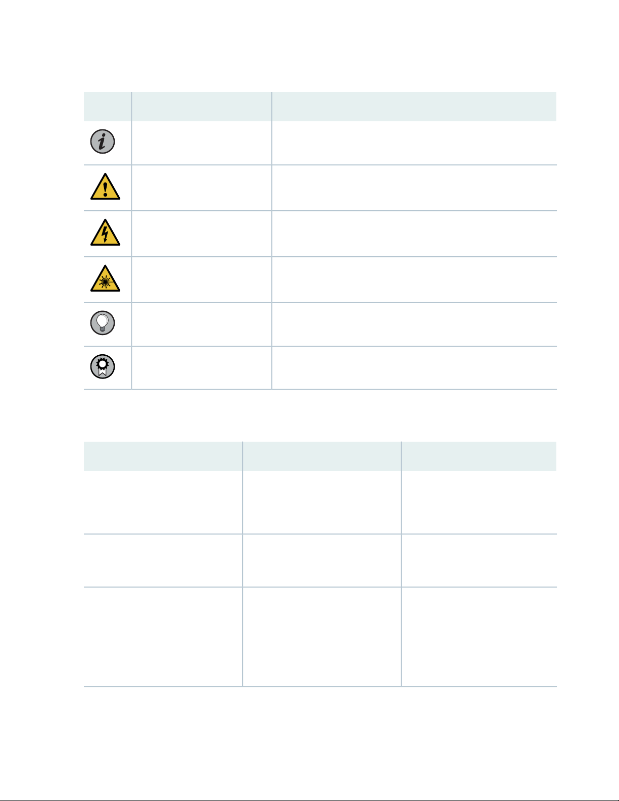
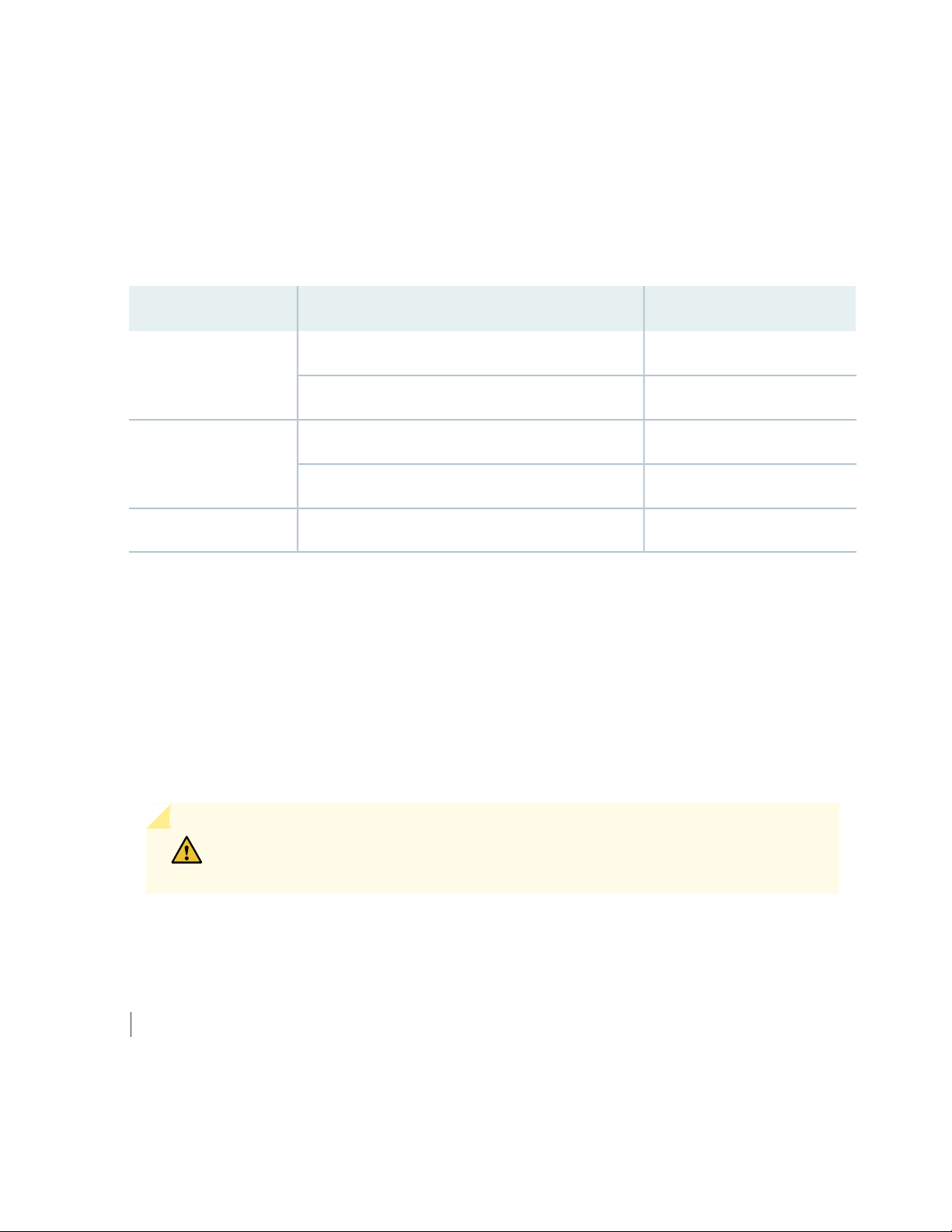
Table 1: Notice Icons
xvi
DescriptionMeaningIcon
Indicates important features or instructions.Informational note
Caution
Indicates a situation that might result in loss of data or hardware
damage.
Alerts you to the risk of personal injury or death.Warning
Alerts you to the risk of personal injury from a laser.Laser warning
Indicates helpful information.Tip
Alerts you to a recommended use or implementation.Best practice
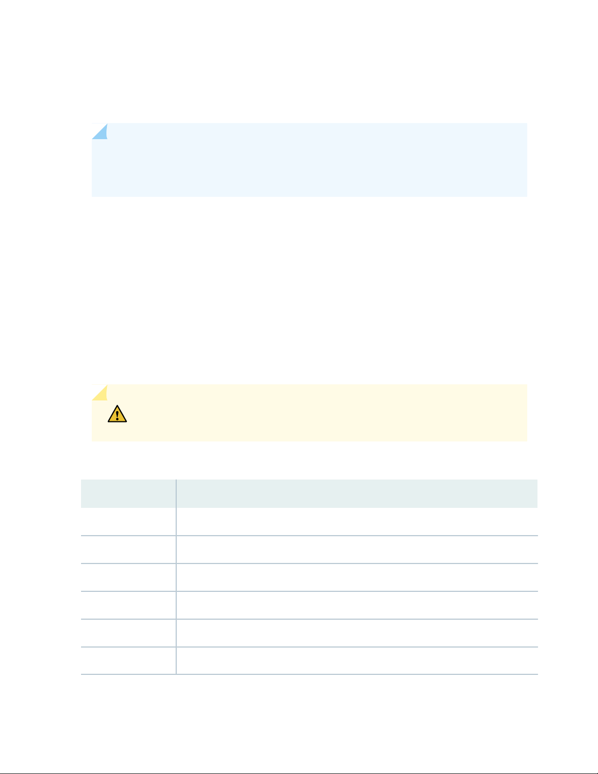
Table 2 on page xvi defines the text and syntax conventions used in this guide.
Table 2: Text and Syntax Conventions
ExamplesDescriptionConvention
Fixed-width text like this
Italic text like this
Represents text that you type.Bold text like this
Represents output that appears on
the terminal screen.
Introduces or emphasizes important
•
new terms.
Identifies guide names.
•
Identifies RFC and Internet draft
•
titles.
To enter configuration mode, type
the configure command:
user@host> configure
user@host> show chassis alarms
No alarms currently active
A policy term is a named structure
•
that defines match conditions and
actions.
Junos OS CLI User Guide
•
RFC 1997, BGP Communities
•
Attribute
Page 17

Table 2: Text and Syntax Conventions (continued)
xvii
ExamplesDescriptionConvention
Italic text like this
Text like this
< > (angle brackets)
| (pipe symbol)
Represents variables (options for
which you substitute a value) in
commands or configuration
statements.
Represents names of configuration
statements, commands, files, and
directories; configuration hierarchy
levels; or labels on routing platform
components.
variables.
Indicates a choice between the
mutually exclusive keywords or
variables on either side of the symbol.
The set of choices is often enclosed
in parentheses for clarity.
Configure the machine’s domain
name:
[edit]
root@# set system domain-name
domain-name
To configure a stub area, include
•
the stub statement at the [edit
protocols ospf area area-id]
hierarchy level.
The console port is labeled
•
CONSOLE.
stub <default-metric metric>;Encloses optional keywords or
broadcast | multicast
(string1 | string2 | string3)
# (pound sign)
[ ] (square brackets)
Indention and braces ( { } )
; (semicolon)
GUI Conventions
Indicates a comment specified on the
same line as the configuration
statement to which it applies.
Encloses a variable for which you can
substitute one or more values.
Identifies a level in the configuration
hierarchy.
Identifies a leaf statement at a
configuration hierarchy level.
rsvp { # Required for dynamic MPLS
only
community name members [
community-ids ]
[edit]
routing-options {
static {
route default {
nexthop address;
retain;
}
}
}
Page 18
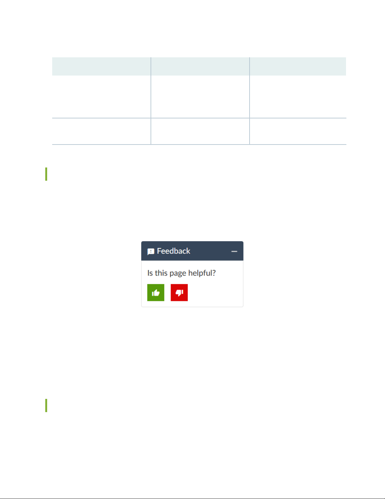
Table 2: Text and Syntax Conventions (continued)
xviii
ExamplesDescriptionConvention
Bold text like this
> (bold right angle bracket)
Represents graphical user interface
(GUI) items you click or select.
Separates levels in a hierarchy of
menu selections.
In the Logical Interfaces box, select
•
All Interfaces.
To cancel the configuration, click
•
Cancel.
In the configuration editor hierarchy,
select Protocols>Ospf.
Documentation Feedback
We encourage you to provide feedback so that we can improve our documentation. You can use either
of the following methods:
Online feedback system—Click TechLibrary Feedback, on the lower right of any page on the Juniper
•
Networks TechLibrary site, and do one of the following:
Click the thumbs-up icon if the information on the page was helpful to you.
•
Click the thumbs-down icon if the information on the page was not helpful to you or if you have
•
suggestions for improvement, and use the pop-up form to provide feedback.
E-mail—Send your comments to techpubs-comments@juniper.net. Include the document or topic name,
•
URL or page number, and software version (if applicable).
Requesting Technical Support
Technical product support is available through the Juniper Networks Technical Assistance Center (JTAC).
If you are a customer with an active Juniper Care or Partner Support Services support contract, or are
Page 19

covered under warranty, and need post-sales technical support, you can access our tools and resources
online or open a case with JTAC.
JTAC policies—For a complete understanding of our JTAC procedures and policies, review the JTAC User
•
Guide located at https://www.juniper.net/us/en/local/pdf/resource-guides/7100059-en.pdf.
Product warranties—For product warranty information, visit https://www.juniper.net/support/warranty/.
•
JTAC hours of operation—The JTAC centers have resources available 24 hours a day, 7 days a week,
•
365 days a year.
Self-Help Online Tools and Resources
For quick and easy problem resolution, Juniper Networks has designed an online self-service portal called
the Customer Support Center (CSC) that provides you with the following features:
Find CSC offerings: https://www.juniper.net/customers/support/
•
Search for known bugs: https://prsearch.juniper.net/
•
xix
Find product documentation: https://www.juniper.net/documentation/
•
Find solutions and answer questions using our Knowledge Base: https://kb.juniper.net/
•
Download the latest versions of software and review release notes:
•
https://www.juniper.net/customers/csc/software/
Search technical bulletins for relevant hardware and software notifications:
•
https://kb.juniper.net/InfoCenter/
Join and participate in the Juniper Networks Community Forum:
•
https://www.juniper.net/company/communities/
Create a service request online: https://myjuniper.juniper.net
•
To verify service entitlement by product serial number, use our Serial Number Entitlement (SNE) Tool:
https://entitlementsearch.juniper.net/entitlementsearch/
Creating a Service Request with JTAC
You can create a service request with JTAC on the Web or by telephone.
Visit https://myjuniper.juniper.net.
•
Call 1-888-314-JTAC (1-888-314-5822 toll-free in the USA, Canada, and Mexico).
•
For international or direct-dial options in countries without toll-free numbers, see
https://support.juniper.net/support/requesting-support/.
Page 20

1
CHAPTER
EX8208 System Overview
EX8208 System Overview | 21
EX8208 Chassis | 37
EX8208 Cooling System | 53
EX8200 Power System | 56
EX8208 Host Subsystem | 78
EX8200 Line Cards | 83
Page 21
EX8208 System Overview
IN THIS SECTION
EX8208 Switch Hardware Overview | 21
EX8208 Switch Configurations | 27
EX8208 Switch Hardware and CLI Terminology Mapping | 29
Chassis Physical Specifications of an EX8208 Switch | 33
Field-Replaceable Units in an EX8208 Switch | 35
EX8208 Switch Hardware Overview
21
IN THIS SECTION
Benefits of the EX8208 Switch | 22
Software | 22
Chassis Physical Specifications, LCD Panel, and Backplane | 22
Routing Engines and Switch Fabric | 23
Line Cards | 24
Cooling System | 25
Power Supplies | 26
Juniper Networks EX8208 Ethernet Switches provide high performance, scalable connectivity, and
carrier-class reliability for high-density environments such as campus-aggregation and data-center networks.
The EX8208 switch is a modular system that provides high availability and redundancy for all major hardware
components, including Routing Engines, switch fabric, fan tray (redundant fans), and power supplies.
You can form an EX8200 Virtual Chassis by connecting individual EX8200 switches to an XRE200 External
Routing Engine. A Virtual Chassis is multiple switches connected together that operate as a single network
entity.
Page 22

You can manage EX8208 switches using the same interfaces that you use for managing other devices
running the Juniper Networks Junos operating system (Junos OS)—the command-line interface (CLI), the
J-Web graphical interface, and the Network and Security Manager (NSM).
Benefits of the EX8208 Switch
Support for Virtual Chassis—EX8208 switches support Virtual Chassis technology. You can configure
EX8200 switches in a Virtual Chassis and manage and operate them as a single network entity by using
the XRE200 External Routing Engine.
High capacity—With a total capacity of up to 6.2 Terabits per second (Tbps), EX8208 is a powerful modular
platform that delivers the performance, scalability, and high availability required for high-density data
center, campus aggregation, and core switching environments.
Support for Juniper Networks Service Now solution—EX8200 switches support the Juniper Networks
Service Now solution, a comprehensive set of tools that enable Juniper Networks J-Care Technical Service
offerings to automate the delivery of tailored, proactive network intelligence and support services.
22
Software
The Juniper Networks EX Series Ethernet Switches run Junos OS, which provides Layer 2 and Layer 3
switching, routing, and security services. The same Junos OS code base that runs on EX Series switches
also runs on all Juniper Networks M Series, MX Series, and T Series routers and SRX Series Services
Gateways.
Chassis Physical Specifications, LCD Panel, and Backplane
The EX8208 switch is 14 rack units (14 U) in size (1/3 rack). Three EX8208 switches can fit in a standard
42 U rack. Each EX8208 switch is designed to optimize rack space and cabling. See Figure 1 on page 23.
Page 23
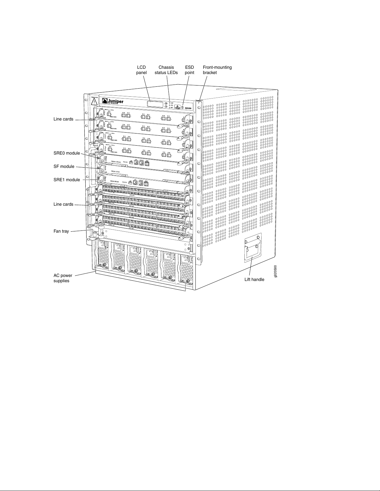
Figure 1: EX8208 Switch
g020500
Fan tray
Line cards
SRE1 module
SF module
SRE0 module
AC power
supplies
Lift handle
Line cards
ESD
point
Front-mounting
bracket
Chassis
status LEDs
LCD
panel
23
The EX8208 switch has a chassis-level LCD panel that displays Routing Engine and switch fabric status as
well as chassis components’ alarm information for rapid problem identification. The LCD panel provides
a user-friendly interface for performing initial switch configuration, rolling back a configuration, or restoring
the switch to its default settings. See LCD Panel in an EX8200 Switch.
The EX8208 chassis backplane distributes the data, control, and management signals to various system
components along with distributing power throughout the system.
See “Chassis Physical Specifications of an EX8208 Switch” on page 33.
Routing Engines and Switch Fabric
Switching functionality, system management, and system control functions of an EX8208 switch are
performed by a Switch Fabric and Routing Engine (SRE) module. See “Switch Fabric and Routing Engine
(SRE) Module in an EX8208 Switch” on page 78. An SRE module contains a Routing Engine and switch
fabric. The SRE modules are field-replaceable units (FRUs) that are installed in the front of the chassis in
Page 24

the slots labeled SRE0 and SRE1. See “Slot Numbering for an EX8208 Switch” on page 40. A base
configuration EX8208 switch has one SRE module. A redundant configuration EX8208 switch has a second
SRE module. See “EX8208 Switch Configurations” on page 27.
The Switch Fabric (SF) module, working with the SRE module, provides the necessary switching functionality
to a base configuration EX8208 switch. The SF module is installed in the front of the chassis in the slot
labeled SF. In a redundant configuration, the SF module provides full 2+1 switch fabric redundancy to the
switch. See “Switch Fabric (SF) Module in an EX8208 Switch” on page 81.
The EX8208 switch can also be connected to an XRE200 External Routing Engine. An XRE200 External
Routing Engine is used to connect multiple EX8200 switches into a Virtual Chassis. See XRE200 External
Routing Engine Hardware Overview.
Line Cards
The EX8208 switch features eight horizontal line card slots and supports line rate for each line card. The
line cards in EX8200 switches combine a Packet Forwarding Engine and Ethernet interfaces on a single
assembly. Line cards are FRUs that can be installed in the line card slots labeled 0 through 7 on the front
of the switch chassis. See “Slot Numbering for an EX8208 Switch” on page 40. All line cards are
hot-removable and hot-insertable.
24
Twelve line cards are available for EX8200 switches. The extra-scale line card models provide larger IPv4
and IPv6 route table sizes than the non-extra-scale models to store more unicast routes.
Table 3 on page 24 shows the model numbers and descriptions of the line cards available for EX8200
switches.
Table 3: Line Cards Available for EX8200 Switches
Additional InformationDescriptionModel
8-port SFP+ line cardEX8200-8XS
8-port SFP+ line card, extra-scaleEX8200-8XS-ES
40-port SFP+ line cardEX8200-40XS
40-port SFP+ line card, extra-scaleEX8200-40XS-ES
“8-port SFP+ Line Card in an EX8200 Switch”
on page 86
“8-port SFP+ Line Card in an EX8200 Switch”
on page 86
“40-port SFP+ Line Card in an EX8200
Switch” on page 88
“40-port SFP+ Line Card in an EX8200
Switch” on page 88
EX8200-2XS-40P
“EX8200-2XS-40P Line Card” on page 9240-port PoE+ with 4-port SFP and
2-port SFP+ line card
Page 25

Table 3: Line Cards Available for EX8200 Switches (continued)
25
Additional InformationDescriptionModel
EX8200-2XS-40T
2-port SFP+ line card
48-port RJ-45 line cardEX8200-48T
48-port RJ-45 line card, extra-scaleEX8200-48T-ES
48-port SFP line cardEX8200-48F
48-port SFP line card, extra-scaleEX8200-48F-ES
“EX8200-2XS-40T Line Card” on page 9440-port RJ-45 with 4-port SFP and
“EX8200-48PL Line Card” on page 9748-port PoE+ 20 Gbps line cardEX8200-48PL
“EX8200-48TL Line Card” on page 9948-port RJ-45 20 Gbps line cardEX8200-48TL
“48-Port RJ-45 Line Card in an EX8200
Switch” on page 103
“48-Port RJ-45 Line Card in an EX8200
Switch” on page 103
“48-Port SFP Line Card in an EX8200 Switch”
on page 101
“48-Port SFP Line Card in an EX8200 Switch”
on page 101
NOTE: We recommend that you do not install extra-scale line card models and non-extra-scale
models in the same switch or Virtual Chassis. If you install extra-scale line cards in a switch or
Virtual Chassis that has non-extra-scale models installed, the IPv4 and IPv6 route table sizes
default to those of the non-extra-scale models and you will not get the benefit of the increased
table sizes of the extra-scale models.
You will experience these decreased route table sizes in a Virtual Chassis even when the
non-extra-scale line cards are installed in one member switch and the extra-scale line cards are
installed in another member switch.
Cooling System
The cooling system in an EX8208 switch consists of a hot-removable and hot-insertable FRU fan tray. The
fan tray contains 12 fans. The fan tray installs vertically on the left front of the chassis and provides
side-to-side chassis cooling. See “EX8208 Cooling System” on page 53.
Page 26
Power Supplies
Power supplies for the EX8208 switch are fully redundant, load-sharing, and hot-removable and
hot-insertable (FRUs. Each EX8208 switch chassis can hold up to six AC or DC power supplies.
Table 4 on page 26 shows the details of the power supplies available for EX8208 switches.
Table 4: Power Supplies Supported on EX8208 Switches
Output PowerInput VoltagePower Supply
1200 WLow-voltage line (100-120 VAC)2000 W AC
2000 WHigh-voltage line (200-240 VAC)
Not supportedLow-voltage line (100-120 VAC)3000 W AC
3000 WHigh-voltage line (200-240 VAC)
26
2000 W-40 VDC through -72VDC2000 W DC
Only two AC power supplies (provided) are required to power on the base AC configuration switch. The
redundant AC configuration ships with six AC power supplies to provide the capacity to power the system
using N+1 or N+N power redundancy. See “AC Power Supply in an EX8200 Switch” on page 56 and
“EX8208 Switch Configurations” on page 27.
The redundant DC configuration ships with four DC power supplies. The dual inputs of the DC supplies
provide direct support for N+N power redundancy. The redundant configuration also provides sufficient
capacity for N+1 redundancy in most configurations; if necessary, up to two additional DC supplies can
be added to the system. See “DC Power Supply in an EX8200 Switch” on page 70 and “EX8208 Switch
Configurations” on page 27.
CAUTION: Mixing different types of power supplies (AC and DC) in the same chassis
is not supported.
SEE ALSO
EX8200 Virtual Chassis Overview
Page 27

EX8208 Switch Configurations
Table 5 on page 27 lists the seven sample hardware configurations for an EX8208 switch—base (AC),
redundant (AC and DC versions), and fully loaded chassis (AC and DC versions)—and the components
included in each configuration.
The switch is shipped in only four of these seven configurations: base (AC with 2000 W AC power supplies),
base (AC with 3000 W AC power supplies), redundant (AC with 2000 W AC power supplies), and redundant
(DC).
Table 5: EX8208 Switch Hardware Configurations
Configuration ComponentsSwitch Configuration
27
Base configuration (AC with 2000 W AC power supplies)
Base configuration (AC with 3000 W AC power supplies)
Redundant configuration (AC with 2000 W AC power
supplies)
Chassis with backplane
•
One fan tray
•
One Switch Fabric and Routing Engine (SRE) module
•
One Switch Fabric (SF) module
•
Two 2000 W AC power supplies
•
Two power cords
•
Eight line card cover panels
•
Four power supply cover panels
•
Chassis with backplane
•
One fan tray
•
One Switch Fabric and Routing Engine (SRE) module
•
One Switch Fabric (SF) module
•
Two 3000 W AC power supplies
•
Two power cords
•
Eight line card cover panels
•
Four power supply cover panels
•
Chassis with backplane
•
One fan tray
•
Two SRE modules
•
One SF module
•
Six 2000 W AC power supplies
•
Six power cords
•
Eight line card cover panels
•
Page 28

Table 5: EX8208 Switch Hardware Configurations (continued)
Configuration ComponentsSwitch Configuration
28
Redundant configuration (DC)
Fully loaded chassis configuration (AC with 2000 W AC
power supplies)
Fully loaded chassis configuration (AC with 3000 W AC
power supplies)
Chassis with backplane
•
One fan tray
•
Two SRE modules
•
One SF module
•
Four 2000 W DC power supplies
•
16 DC power cable lugs
•
Eight line card cover panels
•
Chassis with backplane
•
One fan tray
•
Two SRE modules
•
One SF module
•
Six 2000 W AC power supplies
•
Six power cords
•
Eight line cards
•
Chassis with backplane
•
One fan tray
•
Two SRE modules
•
One SF module
•
Six 3000 W AC power supplies
•
Six power cords
•
Eight line cards
•
Fully loaded chassis configuration (DC)
Chassis with backplane
•
One fan tray
•
Two SRE modules
•
One SF module
•
Six 2000 W DC power supplies
•
24 DC power cable lugs
•
Eight line cards
•
NOTE: You can install up to eight line cards (any combination of line cards) in the switch.
Page 29

NOTE: Line cards are not part of the base or redundant configuration. You must order them
separately.
NOTE: If you want to purchase additional power supplies (AC or DC) for your switch
configuration, you must order them separately.
EX8208 Switch Hardware and CLI Terminology Mapping
This topic describes the hardware terms used in EX8208 switch documentation and the corresponding
terms used in the Junos OS command line interface (CLI). See Table 6 on page 29.
29
Table 6: CLI Equivalents of Terms Used in Documentation for EX8208 Switches
Hardware
Item (CLI)
Item In
DocumentationValue (CLI)Description (CLI)
Switch chassis–EX8208Chassis
Backplane–EX8208-BP-SBackplane
Additional Information
“Chassis Physical
Specifications of an
EX8208 Switch” on
page 33
“Backplane in an EX8208
Switch” on page 49
Page 30

Table 6: CLI Equivalents of Terms Used in Documentation for EX8208 Switches (continued)
30
Hardware
Item (CLI)
CB (n)
One of the
following:
EX8208-SRE320
•
EX8208-SF320
•
n is a value in the range
of 0–2.
Multiple line items appear
in the CLI if more than
one control board (CB) is
installed in the chassis.
CB0 and CB1 are always
SRE modules.
CB2 is always the SF
module.
Item In
DocumentationValue (CLI)Description (CLI)
The switch does not
have actual control
boards; see the
following entries for the
equivalent item on the
switch:
Switch Fabric and
Routing Engine (SRE)
module
Switch Fabric (SF)
module
Additional Information
“Switch Fabric and
Routing Engine (SRE)
Module in an EX8208
Switch” on page 78
“Switch Fabric (SF)
Module in an EX8208
Switch” on page 81
Page 31

Table 6: CLI Equivalents of Terms Used in Documentation for EX8208 Switches (continued)
31
Hardware
Item (CLI)
FPC (n)
On EX8200
standalone
switches:
Abbreviated name
of the Flexible PIC
Concentrator
(FPC)
One of the
following:
EX8200-8XS
•
EX8200-40F
•
EX8200-48F
•
EX8200-48T
•
On EX8200 Virtual
Chassis:
Slot number of
•
the line card
within the
Virtual Chassis:
FPC 0-15
•
FPC 16-31
•
n is a value in the range
of 0–7. The value
corresponds to the line
card slot number in which
the line card is installed.
On Virtual Chassis
member 0, n is a value in
the range of 0–15 ; on
member 1, n is a value in
the range of 16–31.
Item In
DocumentationValue (CLI)Description (CLI)
Line card (The switch
does not have actual
FPCs–the line cards are
the FPC equivalents on
the switch.)
Slot number of the line
card within the Virtual
Chassis
Additional Information
8-port SFP+ Line Card
•
in an EX8200 Switch
on page 86
40-port SFP+ Line
•
Card in an EX8200
Switch on page 88
48-Port SFP Line Card
•
in an EX8200 Switch
on page 101
48-Port RJ-45 Line
•
Card in an EX8200
Switch on page 103
Understanding
•
Interface Naming
Conventions
Network Port Interface
•
Names on an EX8200
Virtual Chassis
Xcvr (n)
PSU (n)
Abbreviated name
of the transceiver
One of the
following:
EX8200-AC2K
•
EX8200-AC3K
•
EX8200-DC2K
•
the number of the port in
which the transceiver is
installed.
of 0–5. The value
corresponds to the power
supply slot number.
Optical transceiversn is a value equivalent to
AC or DC power supplyn is a value in the range
Fan tray–EX8208-FTFan tray
“Pluggable Transceivers
Supported on EX8200
Switches” on page 128
AC Power Supply in an
•
EX8200 Switch on
page 56
DC Power Supply in
•
an EX8200 Switch on
page 70
“EX8208 Cooling
System” on page 53
Page 32

Table 6: CLI Equivalents of Terms Used in Documentation for EX8208 Switches (continued)
32
Hardware
Item (CLI)
Plane (n)
This field indicates:
State of the
•
fabric plane:
Active
•
Spare
•
Check State
•
Status of the
•
Packet
Forwarding
Engine (PFE) in
each fabric
plane:
Links OK
•
Error
•
of 0–11.
Item In
DocumentationValue (CLI)Description (CLI)
LCD panelValue of n is always 0.EX8200 LCDLCD (n)
Additional Information
LCD Panel in an EX8200
Switch
show chassis fabric planeFabric planen is a value in the range
–DPC (n)
n is a value in the range
of 0–7.
have actual Dense Port
Concentrators
(DPCs)–the line cards
are the DPC equivalents
on the switch.
–Value of n is always 0.–PIC (n)
show chassis fabric mapThe switch does not
Understanding
•
Interface Naming
Conventions
Network Port Interface
•
Names on an EX8200
Virtual Chassis
Page 33

Chassis Physical Specifications of an EX8208 Switch
The EX8208 switch chassis is a rigid sheet-metal structure that houses the other switch components.
Table 7 on page 33 summarizes the physical specifications of the EX8208 switch chassis. See
Figure 2 on page 34.
Table 7: Physical Specifications of the EX8208 Switch Chassis
ValueDescription
24.25 in. (61.6 cm)Chassis height
33
Chassis width
Chassis depth
Weight
17.25 in. (43.82 cm)
•
The outer edges of the front-mounting brackets extend the width to 19 in.
•
(48.3 cm).
20 in. (50.8 cm)
•
The depth from the front-mounting bracket to chassis rear is 20.69 in.
•
(52.6 cm).
Chassis with backplane: 89 lb (41 kg)
•
Base configuration: 149 lb (68 kg)
•
Redundant configuration: 187 lb (85 kg)
•
Fully loaded chassis: 284 lb (129 kg)
•
See “EX8208 Switch Configurations” on page 27.
NOTE: The fully loaded chassis weight includes the heaviest line cards in all
eight slots. If your switch configuration has lighter line cards, the fully loaded
chassis weight will be in the 268–284 lb (122–129 kg) range.
Page 34

Figure 2: EX8208 Switch
g020500
Fan tray
Line cards
SRE1 module
SF module
SRE0 module
AC power
supplies
Lift handle
Line cards
ESD
point
Front-mounting
bracket
Chassis
status LEDs
LCD
panel
34
NOTE: Figure 2 on page 34 shows line cards that have 2-in.-long ejector levers. An earlier version
of 8-port SFP+ line card, 48-port RJ-45 line card, and 48-port SFP line card has 4-in.-long ejector
levers.
You can mount an EX8200 switch on a standard 19-in. four-post rack or a standard 800-mm enclosed
cabinet. Up to three EX8208 switches can be installed in a standard (42 rack unit (U)) rack provided the
rack can handle their combined weight.
Lift handles are provided on either side of the switch to facilitate the handling of a chassis with only the
backplane installed.
Page 35

WARNING: Do not use the lift handles to lift the chassis unless the chassis is empty
(that is, contains only the backplane). Failure to heed this warning can result in injury.
See “Mounting an EX8208 Switch on a Rack or Cabinet Using a Mechanical Lift” on
page 157 or “Mounting an EX8208 Switch on a Rack or Cabinet Without Using a
Mechanical Lift” on page 159 for instructions for moving a loaded chassis.
Field-Replaceable Units in an EX8208 Switch
Field-replaceable units (FRUs) are switch components that you can replace at your site. The switch uses
these types of FRUs:
Hot-insertable and hot-removable—You can remove and replace these components without powering
•
off the switch or disrupting the switching function.
35
Hot-pluggable—You can remove and replace these components without powering off the switch, but
•
the switching function is interrupted until you replace the component.
Table 8 on page 35 lists the FRUs for the EX8208 switch and their types.
Table 8: FRUs in an EX8208 Switch
TypeFRU
Hot-insertable and hot-removable.Power supplies
Hot-insertable and hot-removable.Fan tray
Switch Fabric and Routing Engine (SRE) module
Redundant configuration:
Primary SRE module is hot-pluggable.
•
Backup SRE module is hot-insertable and
•
hot-removable.
Base configuration:
Switch must be disabled before the SRE module is
•
removed. See “Taking the SRE Module Offline in an
EX8208 Switch” on page 251.
See “EX8208 Switch Configurations” on page 27.
Page 36

Table 8: FRUs in an EX8208 Switch (continued)
36
TypeFRU
Switch Fabric (SF) module
Line cards
See “Pluggable Transceivers Supported on EX8200
Switches” on page 128 for the Junos OS release in which the
transceivers were introduced.
Redundant configuration:
SF module is hot-insertable and hot-removable.
•
Base configuration:
We recommend that you disable the switch before
•
removing the SF module. See “Taking the SF Module
Offline in an EX8208 Switch” on page 257.
See “EX8208 Switch Configurations” on page 27.
Hot-insertable and hot-removable. We recommend that
you take the line cards offline before removing them.
See “Removing a Line Card from an EX8200 Switch” on
page 268.
Hot-insertable and hot-removable.SFP and SFP+ transceivers
NOTE: Line cards are not part of the base or redundant configuration. You must order them
separately.
NOTE: If you have a Juniper J-Care service contract, register any addition, change, or upgrade
of hardware components at
https://www.juniper.net/customers/support/tools/updateinstallbase/ . Failure to do so can
result in significant delays if you need replacement parts. This note does not apply if you replace
existing components with the same type of component.
SEE ALSO
Line Card Model and Version Compatibility in an EX8200 Switch | 84
Page 37

EX8208 Chassis
IN THIS SECTION
Understanding EX8208 Switch Component and Functionality Redundancy | 37
Slot Numbering for an EX8208 Switch | 40
LCD Panel in an EX8200 Switch | 43
Backplane in an EX8208 Switch | 49
Chassis Status LEDs in an EX8200 Switch | 50
Network Port LEDs in an EX8200 Switch | 51
37
Understanding EX8208 Switch Component and Functionality Redundancy
IN THIS SECTION
Hardware Components That Provide Redundancy | 37
Routing Engine and Control Redundancy | 38
Switch Fabric Redundancy | 39
The Juniper Networks EX8208 Ethernet Switch is available as a fully redundant system. A redundant
EX8208 switch configuration is designed so that no single point of failure can cause the entire switch to
fail. See “EX8208 Switch Configurations” on page 27.
Hardware Components That Provide Redundancy
The following hardware components provide redundancy to an EX8208 switch:
SRE modules—An EX8208 switch can have either one Switch Fabric and Routing Engine (SRE) module
•
or two SRE modules. If two SRE modules are installed, one SRE module functions as the primary and
the other functions as the backup. If the primary SRE module fails or is removed the backup module
takes over as the primary SRE module.
Page 38

When the SRE modules are configured for graceful switchover, the backup SRE module automatically
synchronizes its configuration and state with those of the primary SRE module. Any update to the primary
SRE module is replicated on the backup SRE module. If the backup module assumes primary role, packet
forwarding continues through the switch.
Power supplies—You can install up to six AC or six DC power supplies in an EX8208 switch. Each power
•
supply connects to the backplane of the chassis, which distributes the output power produced by the
power supplies to different switch components. (See “Backplane in an EX8208 Switch” on page 49.)
Each power supply provides power to all the components in the switch.
An N+1 power configuration is required for Juniper Networks EX8200 Ethernet Switches. In an N+1
power configuration, if one power supply fails or is removed, the remaining power supplies continue to
supply power for the entire system without interruption. If dual power feed redundancy is required, the
required power configuration is N+N. The DC power supplies provide independent A and B power feeds
so that dual power redundancy is available even in an N+1 power configuration. See “AC Power Supply
in an EX8200 Switch” on page 56 and “DC Power Supply in an EX8200 Switch” on page 70.
Cooling system—The cooling system in an EX8200 switch consists of a single fan tray. The fan tray
•
contains 12 fans. Under normal operating conditions, the fans in the fan tray run at less than full speed.
38
The fans are controlled by two fan tray controllers. The fans are numbered 1 through 12. Fans 1 through
6 are controlled by the first fan tray controller. Fans 7 through 12 are controlled by the second fan tray
controller. If one fan tray controller fails, the other fan tray controller keeps half the fans working. This
allows the switch to continue to operate normally as long as the remaining fans cool the chassis
sufficiently.
The fan tray continues to operate indefinitely and provides sufficient cooling even when a single fan
fails provided the room temperature is within the operating range. See “EX8208 Cooling System” on
page 53.
Routing Engine and Control Redundancy
Each SRE module contains switch fabric circuitry, Routing Engine circuitry, and switch control and
management circuitry. An EX8208 switch can have one SRE module or two SRE modules. If a switch has
two SRE modules, one functions as the primary while the other functions as a backup and is in standby
mode. This provides the switch with full redundancy (1+1) for Routing Engine and switch control
functionality.
Table 9 on page 39 shows the available slots in the EX8208 chassis and the Routing Engine and control
redundancy associated with different SRE module and Switch Fabric (SF) module combinations.
Page 39

Table 9: Routing Engine and Control Redundancy for EX8208 Switches
Switch
Configuration
configuration
configuration
Switch Fabric Redundancy
39
Routing Engine and
Control
RedundancySlot SFSlot SRE1Slot SRE0
NoSF moduleEmptySRE moduleBase configuration
NoSF moduleSRE moduleEmptyBase configuration
YesEmptySRE moduleSRE moduleUser-defined
YesSF moduleSRE moduleSRE moduleRedundant
The switch fabric circuitry in an EX8208 switch is distributed across three modules—two SRE modules and
one SF module. Any two of these three modules must be installed and functional to provide a working
switch fabric with no redundancy. The third module, when present, provides partial redundancy (2+1) for
the switching functionality, such that if any one of the two functional modules becomes nonoperational,
the third module takes over.
Table 10 on page 39 shows the available slots in an EX8208 chassis and the switch fabric redundancy
associated with different SRE module and SF module combinations.
Table 10: Switch Fabric Redundancy for EX8208 Switches
Switch
Configuration
configuration
configuration
Switch Fabric
RedundancySlot SFSlot SRE1Slot SRE0
NoSF moduleEmptySRE moduleBase configuration
NoSF moduleSRE moduleEmptyBase configuration
NoEmptySRE moduleSRE moduleUser-defined
YesSF moduleSRE moduleSRE moduleRedundant
Page 40

Slot Numbering for an EX8208 Switch
IN THIS SECTION
Slot Numbering for SRE and SF Module Slots and Line Card Slots | 40
Slot Numbering for the Power Supply Slots | 42
An EX8208 chassis accepts eight line cards, two Switch Fabric and Routing Engine (SRE) modules, one
Switch Fabric (SF) module, one fan tray, and six power supplies (AC or DC). All 11 slots for the line cards
and the modules run horizontally across the front of the chassis. The fan tray slot runs vertically on the
left of the chassis front. The six power supply slots run vertically across the front bottom of the chassis.
Slot Numbering for SRE and SF Module Slots and Line Card Slots
40
Table 11 on page 40 lists the slot numbers on the EX8208 chassis and the components those slots accept.
Table 11: Slot Numbering for an EX8208 Switch
Components Accepted in SlotSlot Label
Line card0
Line card1
Line card2
Line card3
SRE moduleSRE0
SF moduleSF
SRE moduleSRE1
Line card4
Line card5
Line card6
Page 41

Table 11: Slot Numbering for an EX8208 Switch (continued)
ALM
SYS
MST
g020565
Components Accepted in SlotSlot Label
Line card7
Figure 3 on page 41 shows the slot numbering, which is on the front left of the chassis.
Figure 3: Slot Numbering for an EX8208 Switch
41
NOTE: Figure 3 on page 41 shows line cards that have 2-in.-long ejector levers. An earlier version
of 8-port SFP+ line card, 48-port RJ-45 line card, and 48-port SFP line card has 4-in.-long ejector
levers.
Slots 0 through 7 accept one of the line cards available. See “Installing a Line Card in an EX8200 Switch”
on page 271.
Page 42
Slots SRE0 and SRE1 accept only the SRE module. You can install one SRE module or two SRE modules
based on the configuration of your switch. See “Switch Fabric and Routing Engine (SRE) Module in an
EX8208 Switch” on page 78.
NOTE: We recommend that you install two SRE modules for redundancy. If you install only one
SRE module, we recommend that you install it in the slot SRE0. See “Installing an SRE Module
in an EX8208 Switch” on page 255.
Slot SF accepts only the SF module. See “Switch Fabric (SF) Module in an EX8208 Switch” on page 81. An
EX8208 switch can have either zero SF modules or one SF module based on your switch configuration.
The SF module is keyed so that it does not fit in any other slot in the chassis. See “Installing an SF Module
in an EX8208 Switch” on page 259.
Slot Numbering for the Power Supply Slots
42
The chassis has six vertical slots on its front bottom. You can install up to six power supplies (either all AC
or all DC) in these slots, which are labeled PSU 0 through PSU 5 (from left to right). Table 12 on page 42
lists the slot numbers for the power supplies on an EX8208 switch. See “AC Power Supply in an EX8200
Switch” on page 56 and “DC Power Supply in an EX8200 Switch” on page 70.
CAUTION: Mixing different types of power supplies in the same chassis is not a
supported configuration.
Table 12: Slot Numbering for Power Supply Slots on an EX8208 Switch Chassis Front
Components Accepted in SlotSlot Label
Power supplyPSU 0
Power supplyPSU 1
Power supplyPSU 2
Power supplyPSU 3
Power supplyPSU 4
Power supplyPSU 5
Figure 4 on page 43 shows the slot numbering for the power supply slots in an EX8208 switch.
Page 43

Figure 4: Slot Numbering for Power Supply Slots on an EX8208 Switch Chassis Front
NOTE: Power supplies can be installed in any slot. You do not have to install them in serial order.
See “Installing an AC Power Supply in an EX8200 Switch” on page 240 and “Installing a DC Power
Supply in an EX8200 Switch” on page 245.
43
LCD Panel in an EX8200 Switch
IN THIS SECTION
LCD Panel Modes | 44
LCD Panel Menus | 45
The LCD panel on the top front of the EX8200 switch chassis shows two lines of text with a maximum of
16 characters in each line. The LCD panel displays a variety of information about the switch and provides
menu options to perform basic operations such as initial configuration and switch reboot.
There are two navigation buttons—Menu and Enter—to the right of the LCD panel.
See Figure 5 on page 43.
Figure 5: LCD Panel in an EX8200 Switch
Page 44

You can configure the second line of the LCD panel to display a custom message. If the LCD panel is
configured to display a custom message, the Menu button and the Enter button are disabled. See
“Configuring the LCD Panel on EX Series Switches (CLI Procedure)” on page 202.
The LCD panel has a backlight. If the LCD panel is idle for 60 seconds, the backlight turns off. You can
turn on the backlight by pressing the Menu or Enter button once. After turning on the backlight, you can
toggle between the LCD menus by pressing the Menu button and navigate through the menu options by
pressing the Enter button.
NOTE: The chassis viewer in the J-Web interface also displays the LCD panel. From the J-Web
interface, you can view real-time status information in the LCD panel. See “Dashboard for EX
Series Switches” on page 205.
LCD Panel Modes
44
The LCD panel operates in four modes: boot, idle, status, and maintenance.
The LCD panel operates in boot mode during switch reboot.
The boot mode displays the key milestones in the switch boot process. The boot mode does not have any
menu options. After the boot process is complete, the LCD panel automatically reverts to the Idle menu.
In the idle mode, line two of the Idle menu displays the Status LED modes of the network ports and the
total number of alarms in the system. The number of alarms is updated every second.
The status mode allows you to get status information for the following items:
Switch fabric in Switch Fabric and Routing Engine (SRE) modules in EX8208 switches
•
Routing Engine (RE) and switch fabric in Switch Fabric (SF) module(s) in EX8216 switches
•
Power supplies
•
Fan tray(s) and chassis temperature
•
Junos OS version installed
•
The maintenance mode allows you to cycle through options for configuring and troubleshooting the switch:
System halt
•
Reboot system
•
Load rescue configuration
•
Revert to factory configuration
•
EZSetup
•
Page 45

LCD Panel Menus
The LCD panel has three menus: Idle, Status, and Maintenance. In each of these menus, line one of the
LCD panel displays the hostname of the switch. Toggle between the LCD menus by pressing the Menu
button. Navigate through the menu options by pressing the Enter button.
Table 13 on page 45 describes the LCD panel menu options.
Table 13: LCD Panel Menu Options for the EX8200 Switch
DescriptionMenu
45
Idle
In the Idle menu:
Press Enter to cycle through the Status LED modes, which are port status indicators:
•
ADM (enabled/disabled)
•
SPD (speed)
•
DPX (duplex)
•
POE (Power over Ethernet)
•
See Network Port LEDs in an EX8200 Switch for information on the Status LED.
Press Menu to exit the Idle menu and go to the Status menu.
•
Page 46

Table 13: LCD Panel Menu Options for the EX8200 Switch (continued)
DescriptionMenu
46
Status
The Status menu has the following options:
Switch fabric status—Choose one of the following:
•
Press Enter to display the status of the switch fabric in the SRE modules (SRE0 and SRE1) in
•
EX8208 switches and the SF modules (SF) in EX8216 switches: OK, Fld (failed), ABS (absent)
Press Menu to go to the next option in the Status menu.
•
Power supply status (1)—Choose one of the following:
•
Press Enter to display the status of power supplies 0 and 1: OK, Fld, ABS.
•
Press Menu to go to the next option in the Status menu.
•
Power supply status (2)—Choose one of the following:
•
Press Enter to display the status of power supplies 2, 3, 4, and 5: OK, Fld, ABS.
•
Press Menu to go to the next option in the Status menu.
•
Environment status—Choose one of the following:
•
Press Enter to display the status of the fan tray(s) and the chassis temperature:
•
Fan tray(s) status: OK, Fld, ABS
•
Chassis temperature status: OK, High, Shutdown
•
Press Menu to go to the next option in the Status menu.
•
Junos OS version status—Choose one of the following:
•
Press Enter to display the version of Junos OS for EX Series switches loaded on the switch.
•
Press Menu to go to the next option in the Status menu.
•
EXIT STAT MENU?—Choose one of the following:
•
Press Enter to exit the Status menu.
•
Press Menu to return to the Switch fabric status option.
•
If you do not want users to use Status menu options, disable the entire menu or individual menu
options. See “Configuring the LCD Panel on EX Series Switches (CLI Procedure)” on page 202.
Page 47

Table 13: LCD Panel Menu Options for the EX8200 Switch (continued)
DescriptionMenu
Maintenance
47
Page 48

Table 13: LCD Panel Menu Options for the EX8200 Switch (continued)
DescriptionMenu
The Maintenance menu has the following options:
SYSTEM HALT?—Choose one of the following:
•
Press Enter to halt the primary SRE module in an EX8208 switch or to halt the primary RE module
•
in an EX8216 switch. Press Enter again to confirm the halt.
In a base configuration switch, the primary SRE or RE module will be gracefully halted but not
powered off. Press Enter on your management device or power cycle the switch to bring the
switch back up.
In a redundant configuration, the backup SRE or RE module takes over the primary role when the
primary SRE or RE module is halted. To completely halt the switch, use the request system halt
other-routing-engine CLI command to halt the backup SRE or RE module before halting the
primary SRE or RE module. Press Enter on your management device or power cycle the switch
to bring the switch back up.
See “EX8208 Switch Configurations” on page 27 or EX8216 Switch Configurations for information
on configuration types.
Press Menu to go to the next option in the Maintenance menu.
•
48
SYSTEM REBOOT?—Choose one of the following:
•
Press Enter to reboot the primary SRE or RE module. Press Enter again to confirm the reboot.
•
Press Menu to go to the next option in the Maintenance menu.
•
LOAD RESCUE?—Choose one of the following:
•
Press Enter to roll back the switch to the previous valid configuration. Press Enter again to confirm
•
the rollback.
Press Menu to go to the next option in the Maintenance menu.
•
FACTORY DEFAULT?—Choose one of the following:
•
Press Enter to restore the switch to the factory default configuration. Press Enter again to confirm
•
the restoration. The LCD panel flashes a success or failure message and returns to the Idle menu.
Press Menu to go to the next option in the Maintenance menu.
•
ENTER EZSETUP?—Choose one of the following:
•
Press Enter to launch EZSetup. Press Enter again to confirm the launch.
•
EZSetup configures DHCP and enables the J-Web user interface on the switch. The LCD panel
flashes a success or failure message for approximately 10 seconds and returns to the Idle menu.
Press Menu to go to the next option in the Maintenance menu.
•
NOTE: You can use the EZSetup option only if the switch is in the factory default configuration.
EXIT MAINT MENU?—Choose one of the following:
•
Press Enter to exit the Maintenance menu.
•
Press Menu to return to the SYSTEM HALT option.
•
Page 49

Table 13: LCD Panel Menu Options for the EX8200 Switch (continued)
DescriptionMenu
If you do not want users to use Maintenance menu options, disable the entire menu or individual
menu options. See “Configuring the LCD Panel on EX Series Switches (CLI Procedure)” on page 202.
You can view the information about the LCD panel in EX8200 switches by executing the command show
chassis hardware. It shows the version, part number, serial number, and description of the LCD panel.
SEE ALSO
Chassis Status LEDs in an EX8200 Switch
Connecting and Configuring an EX Series Switch (CLI Procedure) | 194
Connecting and Configuring an EX Series Switch (J-Web Procedure) | 198
49
Backplane in an EX8208 Switch
The backplane is a printed circuit board that forms the back of the line card cage. The Switch Fabric and
Routing Engine (SRE) modules, Switch Fabric (SF) module, power supplies, and line cards plug into the
backplane from the front of the chassis. The backplane contains an EEPROM that stores the serial number
and revision level of the backplane.
The backplane performs the following functions:
Power distribution—The backplane distributes power to all the switch components from the power
•
supplies that plug into it.
Control-signal connectivity—The backplane transports the control signals exchanged by system
•
components for monitoring, control, and management purposes.
Transfer of data between line cards and SRE modules—The backplane provides connectivity for data
•
traffic to and from the line cards and the SRE modules.
WARNING: High levels of electrical energy are distributed across the switch backplane.
Do not touch the backplane connectors, or any component connected to the backplane,
with any metallic object while servicing components installed in the switch.
Page 50

Chassis Status LEDs in an EX8200 Switch
The top front of the chassis of an EX8200 switch has three LEDs on the right side of the LCD panel.
See Figure 6 on page 50.
Figure 6: Chassis Status LEDs
Table 14 on page 50 describes the chassis status LEDs in an EX8200 switch, their colors and states, and
the status they indicate. You can view the colors of the three LEDs remotely through the CLI by issuing
the operational mode command show chassis lcd.
50
Table 14: Chassis Status LEDs in an EX8200 Switch
Yellow
State and DescriptionColorLED Label (Description)
No alarm.UnlitALM (Alarm)
Major alarm.Red
Minor alarm.Yellow
Switch is powered off.UnlitSYS (System)
One or more component failures are generating one or
more alarms.
Switch is operating normally.Green
Switch is powered off.UnlitMST (Primary)
Primary Routing Engine is operational.Green
A major alarm (red) indicates a critical error condition that requires immediate action.
A minor alarm (yellow) indicates a noncritical condition that requires monitoring or maintenance. A minor
alarm that is left unchecked might cause interruption in service or performance degradation.
All three LEDs can be lit simultaneously.
Page 51

SEE ALSO
Link/
Activity
Link/Activity
Network port LEDs:
Status
Status
g040640
Link/Activity
lower port
Link/Activity
upper port
Status
lower port
Status
upper port
Link/
Activity
Status
Chassis Component Alarm Conditions on EX8200 Switches | 300
Understand Alarm Types and Severity Levels on EX Series Switches | 299
Network Port LEDs in an EX8200 Switch
Each network port on the faceplate of a line card has two LEDs. Figure 7 on page 51 shows the network
port LEDs on the line cards.
Figure 7: Network Port LEDs on Line Cards
51
The LEDs labeled Link/Activity in Figure 7 on page 51 indicate link activity.
Table 15 on page 51 describes the Link/Activity LED.
Table 15: Network Port LEDs on Line Cards in an EX8200 Switch—Link/Activity LED
State and DescriptionColorLED
GreenLink/Activity
On steadily—The port and the link are active, but there
•
is no link activity.
Blinking—The port and the link are active, and there is
•
link activity.
Off—The port is not active.
•
The LEDs labeled Status in Figure 7 on page 51 indicate the status of one of the three port parameters.
The port parameters are administrative status, speed, duplex mode, and Power over Ethernet (PoE) status.
Table 16 on page 52 describes the Status LED. From the Idle menu of the LCD panel, use the Enter button
on the LCD panel to toggle between the ADM, SPD, DPX, and POE indicators.
Page 52

Table 16: Network Port LEDs on Line Cards in an EX8200 Switch—Status LED
State, Color, and DescriptionLCD IndicatorLED
52
LED: ADMStatus
LED: SPD
Indicates the administrative status (enabled or disabled).
The status indicators are:
Green—Administrative status enabled.
•
Yellow—The port is down.
•
Unlit—Administrative status disabled.
•
Indicates the speed. The speed indicators are different in
the line cards.
The speed indicators for 8-port SFP+ line cards are:
Unlit—Less than 10 Gbps
•
Green—10 Gbps
•
The speed indicators for 40-port SFP+ line cards are:
Unlit—10 Mbps
•
Green—Blinking—100 Mbps
•
Green—On steadily—1000 Mbps or 10 Gbps
•
The speed indicators for EX8200-2XS-40P line cards are:
Unlit—10 Mbps
•
Green—Blinking—100 Mbps
•
Green—On steadily—1000 Mbps or 10 Gbps
•
The speed indicators for EX8200-2XS-40T line cards are:
Unlit—10 Mbps
•
Green—Blinking—100 Mbps
•
Green—On steadily—1000 Mbps or 10 Gbps
•
The speed indicators for EX8200-48PL line cards are:
Unlit—10 Mbps
•
Green—Blinking—100 Mbps
•
Green—On steadily—1000 Mbps
•
The speed indicators for EX8200-48TL line cards are:
Unlit—10 Mbps
•
Green—Blinking—100 Mbps
•
Green—On steadily—1000 Mbps
•
The speed indicators for 48-port SFP line cards are:
Page 53

Table 16: Network Port LEDs on Line Cards in an EX8200 Switch—Status LED (continued)
State, Color, and DescriptionLCD IndicatorLED
Unlit—10 Mbps
•
Green—Blinking—100 Mbps
•
Green—On steadily—1000 Mbps
•
The speed indicators for 48-port RJ-45 line cards are:
Unlit—10 Mbps
•
Green—Blinking—100 Mbps
•
Green—On steadily—1000 Mbps
•
53
LED: DPX
LED: POE
SEE ALSO
Line Card LEDs in an EX8200 Switch | 105
EX8208 Cooling System
Indicates the duplex mode. The status indicators are:
Green—Port is set to full-duplex mode.
•
Unlit—Port is not set to full-duplex mode.
•
Indicates the PoE mode. The status indicators are:
Green—PoE is enabled on the port and a device is
•
drawing power.
Yellow—PoE is enabled on the port, but no power is
•
drawn from the port.
Unlit—PoE is not enabled on the port.
•
IN THIS SECTION
Fan Tray | 54
Airflow Direction in the EX8208 Switch Chassis | 55
Page 54

The cooling system in an EX8208 switch consists of a single fan tray.
Fan Tray
The fan tray is a hot-insertable and hot-removable field-replaceable unit (FRU). The fan tray contains 12
fans.
The fan tray installs vertically on the left side on the front of the chassis and provides side-to-side chassis
cooling. A handle on the front faceplate facilitates handling of the fan tray. See Figure 8 on page 54.
Figure 8: Fan Tray for an EX8208 Switch
54
The fan tray can be removed and replaced from the front of the chassis. The switch continues to operate
for a limited time (2 minutes) during the replacement of the fan tray without thermal shutdown.
CAUTION: You must replace the fan tray within 2 minutes of removing it.
Page 55

Airflow Direction in the EX8208 Switch Chassis
The air intake to cool the chassis is located on the right side of the chassis. Air is pulled into the chassis
and is pushed thorough the line card cage towards the fan tray. Hot air exhausts from the left side of the
chassis. See Figure 9 on page 55.
Figure 9: Airflow Through the EX8208 Switch Chassis
55
The Switch Fabric and Routing Engine (SRE) module monitors the temperature of switch components.
Under normal operating conditions, the fans in the fan tray run at less than full speed. The fans are controlled
by two fan tray controllers. The fans are numbered 1 through 12. Fans 1 through 6 are controlled by the
first fan tray controller. Fans 7 through 12 are controlled by the second fan tray controller. If one fan tray
controller fails, the other fan tray controller keeps half the fans working. This allows the switch to continue
to operate normally as long as the remaining fans cool the chassis sufficiently.
If a fan fails or the ambient temperature rises above the threshold 113°F (45°C), the speed of the remaining
fans is automatically adjusted to keep the temperature within the acceptable range, 32°F (0°C) through
104°F (40°C).
The fan tray continues to operate indefinitely and provide sufficient cooling even when a single fan fails
provided the room temperature is within the operating range. You can check the status of fans and the
chassis temperature from the Environment Status option in the Status menu on the LCD panel. See LCD
Panel in an EX8200 Switch.
Page 56

You cannot replace a single fan. If one or more fans fail, you must replace the entire fan tray.
WARNING: There is no fan guard on the fans. Be careful to keep your fingers clear
of moving fan blades when you are removing the fan tray.
RELATED DOCUMENTATION
Clearance Requirements for Airflow and Hardware Maintenance for an EX8208 Switch | 116
EX8200 Power System
56
IN THIS SECTION
AC Power Supply in an EX8200 Switch | 56
AC Power Supply LEDs in an EX8200 Switch | 63
AC Power Specifications for EX8200 Switches | 65
AC Power Cord Specifications for an EX8200 Switch | 66
DC Power Supply in an EX8200 Switch | 70
DC Power Supply LEDs in an EX8200 Switch | 72
DC Power Specifications for EX8200 Switches | 75
Grounding Cable and Lug Specifications for EX8200 Switches | 76
AC Power Supply in an EX8200 Switch
IN THIS SECTION
AC Power Supply Description | 57
N+1 Redundancy Configuration of AC Power Supplies | 59
N+N Redundancy Configuration of AC Power Supplies | 60
Page 57

EX8200 switches can use either AC or DC power supplies. This topic describes the AC power supplies in
EX8200 switches.
AC Power Supply Description
The AC power supplies in EX8200 switches are hot-insertable and hot-removable field-replaceable units
(FRUs).
You can install up to six AC power supplies in an EX8200 switch. Power supplies are installed at the bottom
of the chassis in slots PSU 0 through PSU 5 (left to right). All power supplies are accessible from the front
of the chassis.
WARNING: The switch is installed in a restricted-access location. It has a separate
protective earthing terminal on the chassis that must be permanently connected to
earth ground to adequately ground the chassis and protect the operator from electrical
hazards.
57
CAUTION: Before switch installation begins, ensure that a licensed electrician has
attached an appropriate grounding lug to the grounding cable that you supply. Using
a grounding cable with an incorrectly attached lug can damage the switch.
NOTE: All base configuration EX8200 switches are shipped with two power supplies. Cover
panels are installed over the remaining four power supply slots. Additional power supplies can
be added to base configuration switches as necessary.
For details about different switch configurations, see “EX8208 Switch Configurations” on page 27
or EX8216 Switch Configurations.
Each AC power supply weighs approximately 7 lb (3.2 kg) and has an independent 16 A rated AC inlet on
the faceplate. Each inlet requires a dedicated AC power feed. Each AC power supply has a switch labeled
ENABLE, a fan, and three LEDs on the faceplate that indicate the status of the power supply. See
Figure 10 on page 58.
Page 58

Figure 10: AC Power Supply
Each AC power supply comes with a power cord retainer that holds the power cord in place. See
Figure 11 on page 58. The power cord retainer has a clip and an adjustment nut. The L-shaped ends of
the clip hook into the bracket holes on each side of the AC appliance inlet on the faceplate. The adjustment
nut holds the power cord in the correct position. For instructions for installing the power cord retainer,
see “Connecting AC Power to an EX8200 Switch” on page 171.
58
Figure 11: Power Cord Retainer for an AC Power Supply
Each power supply connects to the backplane in an EX8208 switch and to the midplane in an EX8216
switch. The backplane and the midplane distribute the output power produced by the power supplies to
different switch components. Each AC power supply provides power to all the components in the switch.
Each power supply has its own fan and is cooled by its own internal cooling system. The airflow is from
the front of the power supply to the back. Hot air exhausts from the rear of the chassis.
EX8200 switches support both 2000 W AC power supplies and 3000 W AC power supplies.
The 2000 W AC power supply supports both the low-voltage line (100–120 VAC) and the high-voltage
line (200–240 VAC) AC power configurations. In both cases, the output is 52 VDC. The output power is
1200 W for low-voltage line input and 2000 W for high-voltage line input.
Page 59

The 3000 W AC power supply supports only the high-voltage line input (200–240 VAC) AC power
configuration. Low-voltage line input is not supported for the 3000 W AC power supplies on the EX8200
switches. The output is 52 VDC. The output power is 3000 W.
N+1 Redundancy Configuration of AC Power Supplies
N+1 redundancy configuration is required for normal operation of EX8200 switches. In an N+1 redundancy
configuration, if one power supply fails or is removed, the remaining power supplies continue to supply
power for the switch without interruption.
Depending on the configuration type of the switch and the input voltage, determine the number of power
supplies needed (N) for a switch. Install an additional power supply to meet the required N+1 redundancy
configuration. For details about different switch configurations, see “EX8208 Switch Configurations” on
page 27 or EX8216 Switch Configurations.
The tables in this section list the N+1 power requirements for different EX8200 switch configurations:
Table 17 on page 59—Lists the N+1 power requirements of EX8208 switch configurations that use 2000
•
W AC power supplies.
59
Table 18 on page 60—Lists the N+1 power requirements of EX8208 switch configurations that use 3000
•
W AC power supplies.
Table 19 on page 60—Lists the N+1 power requirements of EX8216 switch configurations that use 2000
•
W AC power supplies.
Table 20 on page 60—Lists the N+1 power requirements of EX8216 switch configurations that use 3000
•
W AC power supplies.
Table 17: N+1 Power Redundancy Configurations for Different EX8208 Switch Configurations Using
2000 W AC Power Supplies
Power Supplies
Power Supplies
Needed (N)Input VoltageSwitch Configuration
SFP+ line cards
Needed for N+1
Redundancy
21High-voltage line (200–240 VAC)Base
32Low-voltage line (100–120 VAC)
43High-voltage line (200–240 VAC)Fully loaded with 8-port
65Low-voltage line (100–120 VAC)
Page 60
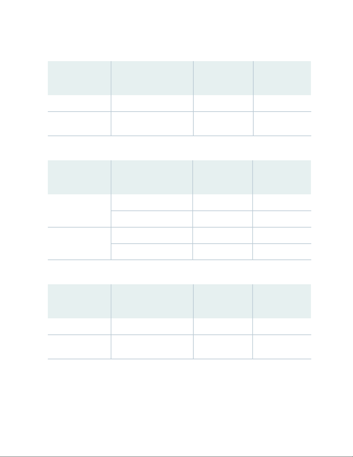
Table 18: N+1 Power Redundancy Configurations for Different EX8208 Switch Configurations Using
3000 W AC Power Supplies
Power Supplies
Power Supplies
Needed (N)Input VoltageSwitch Configuration
SFP+ line cards
Needed for N+1
Redundancy
21High-voltage line (200–240 VAC)Base
32High-voltage line (200–240 VAC)Fully loaded with 8-port
Table 19: N+1 Power Redundancy Configurations for Different EX8216 Switch Configurations Using
2000 W AC Power Supplies
Power Supplies
Power Supplies
Needed (N)Input VoltageSwitch Configuration
Needed for N+1
Redundancy
60
32High-voltage line (200–240 VAC)Base
32Low-voltage line (100–120 VAC)
65High-voltage line (200–240 VAC)Fully loaded with 8-port
SFP+ line cards
Not supportedNot supportedLow-voltage line (100–120 VAC)
Table 20: N+1 Power Redundancy Configurations for Different EX8216 Switch Configurations Using
3000 W AC Power Supplies
Power Supplies
Power Supplies
Needed (N)Input VoltageSwitch Configuration
SFP+ line cards
Needed for N+1
Redundancy
21High-voltage line (200–240 VAC)Base
54High-voltage line (200–240 VAC)Fully loaded with 8-port
N+N Redundancy Configuration of AC Power Supplies
You can optionally configure your switch for N+N redundancy, in which N power supplies can be removed
or can fail and the remaining N power supplies continue to supply power to the switch without interruption.
A common application for N+N redundancy is to have a dual power feed for AC power supplies.
Page 61

How many power supplies you require for N+N redundancy depends on which Junos OS release your
switch is running:
Junos OS Release 10.1 or earlier—Use Table 17 on page 59, Table 18 on page 60, Table 19 on page 60,
•
or Table 20 on page 60 to determine the number of power supplies needed (N). Then multiply the value
of N by two.
NOTE: In Junos OS Release 10.1 or earlier, the power management feature manages switches
for N +1 redundancy only. This means, for example, that power management raises an alarm
if there is insufficient power to maintain N +1 redundancy, but not if there is insufficient power
to maintain N+N redundancy.
Junos OS Release 10.2 or later—Use Table 21 on page 62, Table 22 on page 62, Table 23 on page 62,
•
or Table 24 on page 63 in this section.
Starting with Junos OS Release 10.2, you can configure the power management software to manage the
switch power for N+N redundancy. When you configure power management for N+N redundancy, power
management lowers the maximum chassis power consumption by lowering the maximum fan speed. It
does so to compensate for the extra power that is held in reserve in an N+N configuration than in an N+1
configuration, because of which less power would ordinarily be available to power line cards. By reducing
the maximum chassis power consumption, power management allows the switch to power more line cards.
61
The configuration type of the switch and the input voltage determine the number of power supplies needed
(N) for the switch. You must then install additional power supplies to meet the N+N redundancy
configuration. For details about different switch configurations, see “EX8208 Switch Configurations” on
page 27 or EX8216 Switch Configurations.
The tables in this section list the N+N power requirements for different EX8200 switch configurations:
Table 21 on page 62—Lists the N+N power requirements of EX8208 switch configurations that use
•
2000 W AC power supplies.
Table 22 on page 62—Lists the N+N power requirements of EX8208 switch configurations that use
•
3000 W AC power supplies.
Table 23 on page 62—Lists the N+N power requirements of EX8216 switch configurations that use
•
2000 W AC power supplies.
Table 24 on page 63—Lists the N+N power requirements of EX8216 switch configurations that use
•
3000 W AC power supplies.
Page 62

Table 21: N+N Power Supply Requirements for EX8208 Switch Configurations Using 2000 W AC Power
Supplies (Junos OS Release 10.2 or Later Only)
Power Supplies
Power Supplies
Needed (N)Input VoltageSwitch Configuration
8-port SFP+ line cards
Needed for N+N
Redundancy
21High-voltage line (200–240 VAC)Base
21Low-voltage line (100–120 VAC)
63High-voltage line (200–240 VAC)Fully loaded with
Not Supported4Low-voltage line (100–120 VAC)
Table 22: N+N Power Supply Requirements for EX8208 Switch Configurations Using 3000 W AC Power
Supplies (Junos OS Release 10.2 or Later Only)
62
Power Supplies
Power Supplies
Needed (N)Input VoltageSwitch Configuration
8-port SFP+ line cards
Needed for N+N
Redundancy
21High-voltage line (200–240 VAC)Base
42High-voltage line (200–240 VAC)Fully loaded with
Table 23: N+N Power Supply Requirements for EX8216 Switch Configurations Using 2000 W AC Power
Supplies (Junos OS Release 10.2 or Later Only)
Power Supplies
Power Supplies
Needed (N)Input VoltageSwitch Configuration
8-port SFP+ line cards
Needed for N+N
Redundancy
21High-voltage line (200–240 VAC)Base
42Low-voltage line (100–120 VAC)
Not supported5High-voltage line (200–240 VAC)Fully loaded with
Not supportedNot supportedLow-voltage line (100–120 VAC)
Page 63
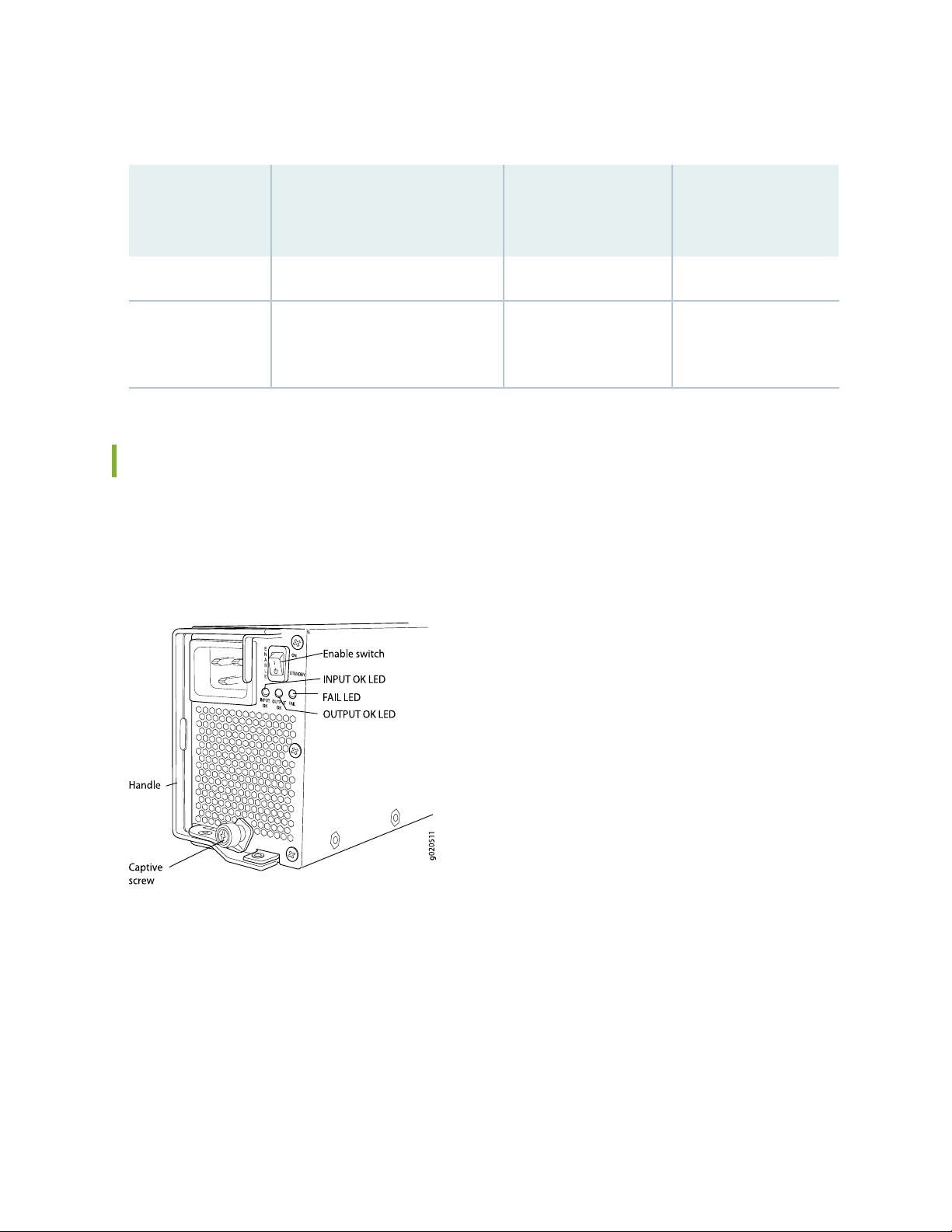
Table 24: N+N Power Supply Requirements for EX8216 Switch Configurations Using 3000 W AC Power
Supplies (Junos OS Release 10.2 or Later Only)
Power Supplies
Switch
Configuration
8-port SFP+ line
cards
Power Supplies
Needed (N)Input Voltage
Needed for N+N
Redundancy
21High-voltage line (200–240 VAC)Base
63High-voltage line (200–240 VAC)Fully loaded with
AC Power Supply LEDs in an EX8200 Switch
63
An AC power supply has three LEDs on its faceplate. These LEDs display information about the status of
the power supply. See Figure 12 on page 63.
Figure 12: AC Power Supply LEDs on an EX8200 Switch
Table 25 on page 64 describes the LEDs on an AC power supply in an EX8200 switch.
Page 64

Table 25: Power Supply LEDs on EX8200 Switches
64
DescriptionStateLED
UnlitINPUT OK
Green
Yellow
NOTE: This LED state
applies only to 2000 W
AC power supplies.
UnlitOUTPUT OK
Indicates one of the following:
Power supply is disconnected from AC power
•
feed.
AC power input voltage is not within normal
•
operating range.
No AC power input.
•
AC power input is high-voltage line
•
(200–240 VAC).
AC power input is low-voltage line
•
(100–120 VAC).
Indicates one of the following:
DC output voltage is not within normal operating
•
range.
Power supply is not supplying DC power
•
correctly.
Green
Yellow
Yellow
DC power output is within normal operating
•
range.
Power supply has been disabled internally by
•
the system.
Power supply is functioning normally.UnlitFAIL
•
On steadily—Power supply has failed.
•
Blinking—Demand for output power exceeds
•
the supply.
Page 65

NOTE: If the INPUT OK LED and the OUTPUT OK LED are unlit, the AC power cord is not
installed properly or the power supply has failed.
If the INPUT OK LED is lit and the OUTPUT OK LED is unlit, the AC power supply is not installed
properly or the power supply has an internal failure.
If the FAIL LED is lit, the power supply has failed and must be replaced. If the FAIL LED is blinking,
add a power supply to balance the power demand and supply.
AC Power Specifications for EX8200 Switches
EX8200 switches can use either AC or DC power supplies.
65
Table 26 on page 65 lists the AC power specifications for a 2000 W power supply used in EX8200 switches.
Table 26: Power Specifications for a 2000 W AC Power Supply in an EX8200 Switch
SpecificationsItem
AC input voltage
AC input current rating
AC output power
Operating range:
Low-voltage line—100–120 VAC
•
High-voltage line—200–240 VAC
•
50–60 HzAC input line frequency
Low-voltage line—13.8 A
•
High-voltage line—12 A
•
Low-voltage line—1200 W
•
High-voltage line—2000 W
•
Table 27 on page 66 lists the AC power specifications for a 3000 W power supply used in EX8200 switches.
Page 66

Table 27: Power Specifications for a 3000 W AC Power Supply in an EX8200 Switch
SpecificationsItem
66
AC input voltage
Operating range:
High-voltage line—200–240 VAC
•
NOTE: Low-voltage line input is not supported for 3000 W AC power
supplies on the EX8216 switch.
50–60 HzAC input line frequency
High-voltage line—16 AAC input current rating
•
High-voltage line—3000 WAC output power
•
AC Power Cord Specifications for an EX8200 Switch
Each AC power supply has a single AC appliance inlet that requires a dedicated AC power feed. Most sites
distribute power through a main conduit that leads to frame-mounted power distribution panels, one of
which can be located at the top of the rack that houses the switch. An AC power cord connects each
power supply to the power distribution panel.
Each detachable AC power cord is 8 feet (approximately 2.5 meters) long. The appliance coupler end of
the cord inserts into the AC appliance inlet on the faceplate of the AC power supply. The coupler type is
C19 as described by the International Electrotechnical Commission (IEC) standard 60320. The plug end
of the power cord fits into the power source outlet that is standard for your geographical location.
NOTE: In North America, AC power cords must not exceed 15 feet (approximately 4.5 meters)
in length, to comply with National Electrical Code (NEC) Sections 400-8 (NFPA 75, 5-2.2) and
210-52 and Canadian Electrical Code (CEC) Section 4-010(3). The cords shipped with the switch
to North America and Canada are in compliance.
Table 28 on page 67 lists the AC power cord specifications for an EX8200 switch for various countries
and regions.
Page 67

Table 28: AC Power Cord Specifications for an EX8200 Switch
Electrical
SpecificationsCountry/Region
67
GraphicJuniper Model NumberPlug Standards
Italy, Switzerland,
and United
Kingdom)
CBL-EX-PWR-C19-ARIRAM Type RA/3/20250 VAC, 16 A, 50 HzArgentina
250 VAC, 15 A, 50 HzAustralia
SAA/3/15
250 VAC, 16 A, 50 HzBrazil
BR/3/20
250 VAC, 16 A, 50 HzIndia
ZA/3
CBL-EX-PWR-C19-AUAS/NZS 3112 Type
CBL-EX-PWR-C19-BRNBR 14136: 2002 Type
CBL-EX-PWR-C19-CHGB 1002 Type PRC/3/16250 VAC, 16 A, 50 HzChina
CBL-EX-PWR-C19-EUCEE (7) VII Type VIIG250 VAC, 16 A, 50 HzEurope (except
CBL-EX-PWR-C19-INSABS 164/1:1992 Type
No
graphic
available.
No
graphic
available.
No
graphic
available.
Page 68

Table 28: AC Power Cord Specifications for an EX8200 Switch (continued)
g021269
Electrical
SpecificationsCountry/Region
CBL-EX-PWR-C19-ILSI 32/1971 Type IL/3250 VAC, 16 A, 50 HzIsrael
CBL-EX-PWR-C19-ITCEI 23-16 Type I/3/16250 VAC, 16 A, 50 HzItaly
68
GraphicJuniper Model NumberPlug Standards
Japan
or 60 Hz
250 VAC, 16 A, 50 Hz
or 60 Hzv
250 VAC, 16 A, 60 Hz
125 VAC, 15 A, 60 Hz
125 VAC, 20 A, 60 Hz
NEMA L6–20P Type NEMA
Locking
NEMA L6–20P Type NEMA
Locking
NOTE: Only for use with
2000 W AC power supply.
CBL-EX-PWR-C19-JPNEMA 6–20 Type N6/20250 VAC, 16 A, 50 Hz
CBL-EX-PWR-C19-JPL
(default)
CBL-EX-PWR-C19-KRCEE (7) VII Type VIIG250 VAC, 16 A, 50 HzKorea
CBL-EX-PWR-C19-USNEMA 6–20 Type N6/20250 VAC, 16 A, 60 HzNorth America
CBL-EX-PWR-C19-USL
(default)
CBL-EX-PWR-C19-US-15NEMA 5–15 Type N5/15
CBL-EX-PWR-C19-US-20NEMA 5–20 Type N5-20
No
graphic
available.
NOTE: Only for use with
2000 W AC power supply.
250 VAC, 16 A, 50 HzSouth Africa
CBL-EX-PWR-C19-SASABS 164/1:1992 Type
ZA/3
CBL-EX-PWR-C19-SZSEV 5934/2 Type 23G250 VAC, 16 A, 50 HzSwitzerland
No
graphic
available.
Page 69

Table 28: AC Power Cord Specifications for an EX8200 Switch (continued)
Electrical
SpecificationsCountry/Region
69
GraphicJuniper Model NumberPlug Standards
250 VAC, 16 A, 50 HzTaiwan
LOCKING
CBL-EX-PWR-C19-TWNEMA L6-20P Type NEMA
CBL-EX-PWR-C19-UKBS 1363/A Type BS89/13250 VAC, 13 A, 50 HzUnited Kingdom
CAUTION: AC power cords for EX8200 switches are intended for use with these
switches only. Do not use the cord for another product.
Power Cable Warning (Japanese)
WARNING: The attached power cable is only for this product. Do not use the cable for another product.
CAUTION: Power cords must not block access to switch components. We recommend
that you route all AC power cord cables through the power cord tray provided with
the switch.
WARNING: The switch is installed in a restricted-access location. It has a separate
protective earthing terminal on the chassis that must be permanently connected to
earth ground to adequately ground the chassis and protect the operator from electrical
hazards.
Page 70
DC Power Supply in an EX8200 Switch
The DC power supplies in EX8200 switches are hot-removable and hot-insertable field-replaceable units
(FRUs).
NOTE: EX8208 switches support 2000 W DC power supplies.
EX8216 switches support 3000 W DC power supplies.
You can install up to six DC power supplies in an EX8200 switch. Power supplies are installed at the bottom
of the chassis in slots labeled PSU 0 through PSU 5 (left to right). See “Slot Numbering for an EX8208
Switch” on page 40 and Slot Numbering for an EX8216 Switch. All power supplies are accessible from the
front of the chassis.
WARNING: The switch is pluggable type A equipment installed in a restricted-access
location. It has a separate protective earthing terminal provided on the chassis. This
separate protective earthing terminal must be permanently connected to earth ground.
70
NOTE: EX8216 switches have two protective earthing terminals provided on the chassis, one
on the left side of the chassis and the other on the rear of the chassis. Only one of these protective
earthing terminals needs to be permanently connected to earth ground. See Chassis Physical
Specifications of an EX8216 Switch for the location of the protective earthing terminals.
NOTE: DC power supplies are shipped only in the redundant configuration of EX8200 switches.
See “EX8208 Switch Configurations” on page 27 for details about different EX8208 switch
configurations.
See EX8216 Switch Configurations for details about different EX8216 switch configurations.
Each DC power supply weighs approximately 7 lb (3.2 kg) and has two independent pairs of DC input lugs
(A: –48V A: RTN and B: – 48V B: RTN ) on the front of the power supply. Each power supply also has an
Enable switch, a fan, and four LEDs on the faceplate that indicate the status of the power supply. See
Figure 13 on page 71.
Page 71

Figure 13: DC Power Supply
NOTE: A 2000 W DC power supply requires a dedicated 60 A circuit breaker for each input DC
feed.
A 3000 W DC power supply requires a dedicated 100 A circuit breaker for each input DC feed.
71
Each DC power supply connects to the backplane in an EX8208 switch and to the midplane in an EX8216
switch. The backplane in an EX8208 switch and the midplane in an EX8216 switch distribute the output
power produced by the power supplies to different switch components. Each DC power supply provides
power to all the components in the switch.
The output of each 2000 W DC power supply is 52 VDC. The output power is 2000 W.
The output of each 3000 W DC power supply is 52 VDC. The output power is 3000 W.
A DC power supply works with only one input DC feed connected. It is able to deliver the full output
power to all chassis components with only one DC feed connected.
Each DC power supply has its own fan and is cooled by its own internal cooling system. The airflow is from
the front of the power supply to the back. Hot air exhausts from the rear of the chassis.
The minimum power configuration required by an EX8200 switch is an N+1 power configuration. In an
N+1 power configuration, if one power supply fails or is removed, the remaining power supplies continue
to supply power for the system without interruption.
The configuration type of the switch and the input voltage determine the number of power supplies needed
(N) for a switch. You must install an additional power supply to meet the required N+1 power redundancy
configuration. The DC power supplies each provide independent A and B power feeds, so that dual power
feed redundancy is available even in an N+1 configuration. See “EX8208 Switch Configurations” on page 27
for details about different EX8208 switch configurations. See EX8216 Switch Configurations for details
about different EX8216 switch configurations.
Page 72

The tables in this section list the N+1 power requirements of different EX8200 switch configurations:
Table 29 on page 72—Lists the N+1 power requirements of EX8208 switch configurations that use 2000
•
W DC power supplies.
Table 30 on page 72—Lists the N+1 power requirements of EX8216 switch configurations that use 3000
•
W DC power supplies.
Table 29: N+1 Power Redundancy Configurations for Different EX8208 Switch Configurations Using
2000 W DC Power Supplies
72
Power Supplies
Needed for N+1
21–40 VDC through
43–40 VDC through
Base
Fully loaded with
8-port SFP+ line cards
Power Supplies Needed
(N)Input VoltageSwitch Configuration
–72 VDC
–72 VDC
Table 30: N+1 Power Redundancy Configurations for Different EX8216 Switch Configurations Using
3000 W DC Power Supplies
Power Supplies
Needed for N+1
21–40 VDC through
54–40 VDC through
Base
Fully loaded with
8-port SFP+ line cards
Power Supplies Needed
(N)Input VoltageSwitch Configuration
–72 VDC
–72 VDC
DC Power Supply LEDs in an EX8200 Switch
A DC power supply has four LEDs on its faceplate: FAIL, OUT OK, A IN OK, and B IN OK LEDs. The text
A or B next to the OK IN LEDs indicates which input lug the LED corresponds to. All four LEDs display
information about the status of the power supply. See Figure 14 on page 73.
NOTE: EX8208 switches support 2000 W DC power supplies.
EX8216 switches support 3000 W DC power supplies.
Page 73

Figure 14: DC Power Supply LEDs in an EX8200 Switch
Table 31 on page 73 describes the LEDs on a DC power supply in EX8200 switches.
Table 31: DC Power Supply LEDs in EX8200 Switches
DescriptionStateLED
73
UnlitA IN OK
Green
Yellow
Red
Indicates one of the following:
Power supply is disconnected from DC power
•
feed.
DC power input voltage is not within normal
•
operating range (-40 VDC through -72 VDC).
No DC power input.
•
DC power input voltage is within normal
•
operating range (–40 VDC through –72 VDC).
DC input is present on the terminals but either
•
the fuse is tripped or the ORing diode is open.
DC power input voltage is reversed in polarity.
•
NOTE: The DC power supply is protected against
reverse polarity input for both DC input feeds.
Page 74

Table 31: DC Power Supply LEDs in EX8200 Switches (continued)
DescriptionStateLED
74
UnlitB IN OK
Green
Yellow
Red
UnlitOUT OK
Indicates one of the following:
Power supply is disconnected from DC power
•
feed.
DC power input voltage is not within normal
•
operating range (-40 VDC through -72 VDC).
No DC power input.
•
DC power input voltage is within the normal
•
operating range (–40 VDC through –72 VDC).
DC input is present on the terminals but either
•
the fuse is tripped or the ORing diode is open.
DC power input voltage is reversed in polarity.
•
NOTE: The DC power supply is protected against
reverse polarity input for both DC input feeds.
Indicates one of the following:
DC output voltage is not within normal operating
•
range.
Power supply is not supplying DC power
•
correctly.
Green
Yellow
Yellow
DC power output is within normal operating
•
range.
Power supply has been disabled internally by
•
the system.
Power supply is functioning normally.UnlitFAIL
•
On steadily—Power supply has failed.
•
Blinking—Demand for output power exceeds
•
the supply.
Page 75

NOTE: If the IN OK LED and the OUT OK LED are unlit, the power cords are not installed
properly or the power supply has failed.
If the IN OK LED is lit green and the OUT OK LED is unlit, the power supply is not installed
properly or the power supply has an internal failure.
If the FAIL LED is lit, the power supply has failed and must be replaced. If the FAIL LED is blinking,
add a power supply to balance the power demand and supply.
DC Power Specifications for EX8200 Switches
Table 32 on page 75 lists the power specifications for the 3000 W DC power supply used in EX8216
switches.
75
Table 32: Power Specifications for a 3000 W DC Power Supply Used in an EX8216 Switch
SpecificationsItem
DC input voltage
Minimum operating voltage: –40 VDC
•
Nominal operating voltage: –48 VDC
•
Operating voltage range: –40 VDC through –72 VDC
•
NOTE: If the input voltage from the DC power source drops below –37.5 VDC through
–39.5 VDC, the switching platform automatically shuts down. During automatic
shutdown, the circuit remains active. When the input voltage returns to –43 VDC
through –44 VDC, the switch automatically starts up again and the system returns to
normal operation within 30 minutes. No operator intervention is required.
75 A maximum at nominal operating voltage (–48 VDC) for each input terminal.DC input current rating
3000 WOutput power
100 AInternal Fuse Protection
Table 33 on page 76 lists the power specifications for the 2000 W DC power supply used in EX8208
switches.
Page 76

Table 33: Power Specifications for a 2000 W DC Power Supply Used in an EX8208 Switch
SpecificationsItem
76
DC input voltage
Minimum operating voltage: –40 VDC
•
Nominal operating voltage: –48 VDC
•
Operating voltage range: –40 VDC through –72 VDC
•
NOTE: If the input voltage from the DC power source drops below –37.5 VDC through
–39.5 VDC, the switching platform automatically shuts down. During automatic
shutdown, the circuit remains active. When the input voltage returns to –43 VDC
through –44 VDC, the switch automatically starts up again and the system returns to
normal operation within 30 minutes. No operator intervention is required.
50 A maximum at nominal operating voltage (–48 VDC) for each input terminal.DC input current rating
2000 WOutput power
100 AInternal Fuse Protection
Grounding Cable and Lug Specifications for EX8200 Switches
To ensure proper operation and to meet safety and electromagnetic interference (EMI) requirements, you
must connect an EX Series switch to earth ground before you connect power to the switch. You must use
the protective earthing terminal on the switch chassis to connect the switch to earth ground.
WARNING: The switch is installed in a restricted-access location. It has a separate
protective earthing terminal on the chassis that must be permanently connected to
earth ground to adequately ground the chassis and protect the operator from electrical
hazards.
CAUTION: Before switch installation begins, ensure that a licensed electrician has
attached an appropriate grounding lug to the grounding cable that you supply. Using
a grounding cable with an incorrectly attached lug can damage the switch.
Page 77

Grounding requirements for EX8200 switches:
Crimp area
6 AWG conductor
All measurements in inches
0.28
diameter
each hole
2.25
0.25 0.370.625
g001188
0.55
End view
0.08
EX8208 switches—A pair of threaded inserts (PEM nuts) is provided on the right side toward the top
•
rear corner of the EX8208 chassis for connecting the switch to earth ground. The grounding points fit
UNC ¼-20 screws. The grounding points are spaced at 0.625 in. (15.86 mm).
The grounding cable that you provide for an EX8208 switch must be 2 AWG (33.6 mm2), minimum 60°C
wire, or as permitted by the local code.
Figure 15 on page 77 shows the grounding lug that attaches to the grounding cable in an EX8208 switch.
Figure 15: Grounding Lug for an EX8208 Switch
77
EX8216 switches—Two pairs of threaded inserts (PEM nuts) are provided on the EX8216 chassis for
•
connecting the switch to earth ground. The first pair is located on the right side toward the top rear
corner of the chassis. The second pair is on the rear of chassis toward the bottom right corner of the
chassis. Both pairs of grounding points fit UNC ¼-20 screws. The grounding points are spaced at 0.625
in. (15.86 mm).
The grounding cable that you provide for an EX8216 switch must be 2 AWG (33.6 mm2), minimum 60°C
wire, or as permitted by the local code.
NOTE: EX8216 switches have two protective earthing terminals provided on the chassis. Only
one of these protective earthing terminals needs to be permanently connected to earth ground.
See Chassis Physical Specifications of an EX8216 Switch for the location of the protective earthing
terminals.
Two grounding lugs are shipped with the EX8216 switch.
Page 78
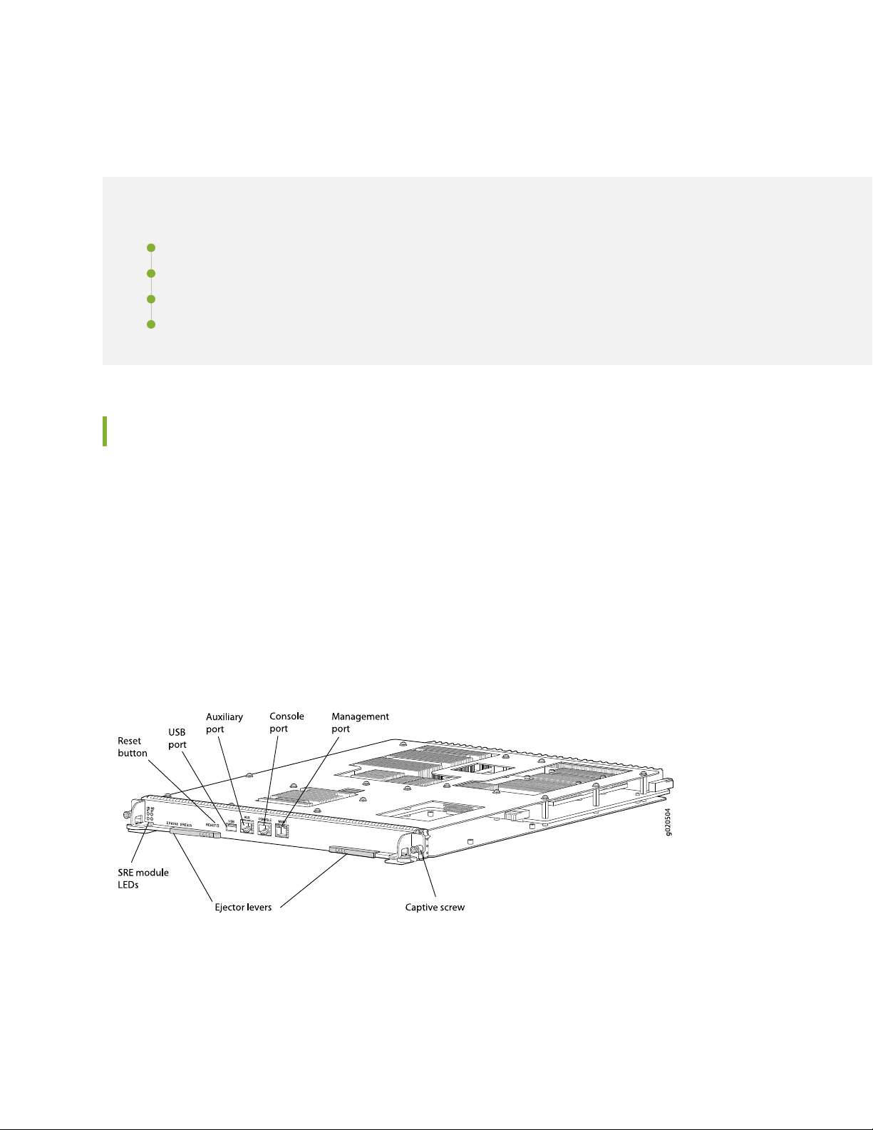
EX8208 Host Subsystem
IN THIS SECTION
Switch Fabric and Routing Engine (SRE) Module in an EX8208 Switch | 78
SRE Module LEDs in an EX8208 Switch | 80
Switch Fabric (SF) Module in an EX8208 Switch | 81
SF Module LEDs in an EX8208 Switch | 82
Switch Fabric and Routing Engine (SRE) Module in an EX8208 Switch
78
The Switch Fabric and Routing Engine (SRE) module performs switching and system management functions
in an EX8208 switch. See Figure 16 on page 78.
You can install one or two SRE modules in an EX8208 switch. A base configuration EX8208 switch has
only one SRE module. See “EX8208 Switch Configurations” on page 27. You can add a second SRE module
to the configuration for Routing Engine and switch control redundancy. See “Understanding EX8208 Switch
Component and Functionality Redundancy” on page 37.
The SRE modules install horizontally into the front of the chassis in slots labeled SRE0 and SRE1.
Figure 16: SRE Module in an EX8208 Switch
Page 79

NOTE: We recommend that you install two SRE modules for redundancy. If you install only one
SRE module, we recommend that you install it in slot SRE0. See “Slot Numbering for an EX8208
Switch” on page 40.
If two SRE modules are installed, one functions as the primary and the other acts as the backup. If the
primary SRE module fails or is removed, the backup takes over as the primary.
If two SRE modules are installed, the backup SRE module is hot-insertable and hot-removable, but the
primary SRE module is hot-pluggable. If only one SRE module is installed, you must halt the SRE module
before removing it.
The SRE module provides these functions:
Provides full fabric connectivity to all line cards installed in the chassis
•
Through the switching plane, provides switching functionality to the switch
•
79
Powers the line cards on and off
•
Controls system resets and boot sequence for the switch
•
Monitors and controls the fan speed, power status for various chassis components, LCD panel and
•
chassis status LEDs
The SRE module has these components:
SRE module LEDs—Indicate system status. See “SRE Module LEDs in an EX8208 Switch” on page 80.
•
Recessed reset button—Power cycles the SRE module when pressed.
•
Take the SRE module offline using the CLI before pressing the reset button. See “Taking the SRE Module
Offline in an EX8208 Switch” on page 251.
USB port—Provides an interface through which you can install the Junos OS manually. See “USB Port
•
Specifications for an EX Series Switch” on page 136.
Auxiliary port—This port is not enabled on the EX8200 switch. It is reserved for future use.
•
Console port—Connects the SRE module to a system console through a cable with an RJ-45 connector.
•
See “Connect a Device to a Management Console Using an RJ-45 Connector” on page 183.
Management port—Connects the SRE module through an Ethernet connection to a management LAN
•
(or any other device that plugs into an Ethernet connection) for out-of-band management. See “Connect
a Device to a Network for Out-of-Band Management” on page 182.
Ejector levers—Used for installing and removing the SRE module.
•
Captive screws—Secure the SRE module in place.
•
Page 80

SRE Module LEDs in an EX8208 Switch
Each Switch Fabric and Routing Engine (SRE) module has four LEDs on the left side of the module’s front
panel. See Figure 17 on page 80. Table 34 on page 80 describes these LEDs, their colors and states, and
the status they indicate.
Figure 17: SRE Module LEDs in an EX8208 Switch
Table 34: SRE Module LEDs of an EX8208 Switch
80
State and DescriptionColorLED Label (Description)
SRE module is powered on.GreenON (Power On)
SRE module is powered off.Unlit
GreenST (Status)
GreenMS (Primary)
On steadily—SRE module is operating normally.
•
Blinking—SRE module is booting.
•
On steadily—SRE module has failed.Yellow
•
SRE module is offline.Unlit
On steadily—SRE module is the primary.
•
Blinking—SRE module is in standby mode.
•
NOTE: For EX8208 switches, running a Junos OS release
prior to Release 10.2R1, the MS led on the backup SRE
module remains unlit. To resolve this issue, upgrade the
switch to Junos OS Release 10.2R1 or higher.
SRE module is powered off.Unlit
Page 81

Table 34: SRE Module LEDs of an EX8208 Switch (continued)
State and DescriptionColorLED Label (Description)
81
GreenSF (Switch Fabric)
On steadily—Switch fabric in the SRE module is operating
•
normally.
Blinking—Switch fabric in the SRE module is in standby
•
mode.
Switch fabric in the SRE module has failed.Yellow
SRE module is powered off.Unlit
Switch Fabric (SF) Module in an EX8208 Switch
The Switch Fabric (SF) module provides switching functionality. See Figure 18 on page 81.
An EX8208 switch can have either zero SF modules or one SF module. The base configuration of an EX8208
switch includes one SF module. See “EX8208 Switch Configurations” on page 27.
Figure 18: SF Module in an EX8208 Switch
The SF module can be installed only in the slot labeled SF. The SF module is keyed so that it does not fit
in the other slots in the chassis. See “Slot Numbering for an EX8208 Switch” on page 40.
In the base configuration, an SF module is used with a single Switch Fabric and Routing Engine (SRE)
module to build a nonredundant system that provides full bandwidth. However, a base configuration
EX8208 switch has no Routing Engine and switch control redundancy or switch fabric redundancy. In a
base configuration, the main function of the SF module is to switch data between line cards. See
“Understanding EX8208 Switch Component and Functionality Redundancy” on page 37.
In a redundant configuration, an SF module is used with two SRE modules to achieve full bandwidth along
with Routing Engine and switch control redundancy and switch fabric redundancy. In a redundant
Page 82

configuration, the main function of the SF module is to provide a redundant switching plane for the switch.
See “Understanding EX8208 Switch Component and Functionality Redundancy” on page 37.
In a redundant configuration, the SF module is hot-pluggable. However, in the base configuration, you
must take the SF module offline before removing it.
The SF module contains logic that determines which SRE module is the primary. The primary SRE module
controls many internal functions of the SF module.
The SF module provides these functions:
Provide redundant data path connectivity for the switch in the redundant configuration
•
Provide nonredundant data path connectivity for the switch in the base configuration
•
The SF module has these components:
SF module LEDs—Indicate system status. See “SF Module LEDs in an EX8208 Switch” on page 82.
•
Ejector levers—Used for installing and removing the SF module.
•
82
Captive screws—Secure the SF module in place.
•
SF Module LEDs in an EX8208 Switch
The Switch Fabric (SF) module has two LEDs on the left side of the module’s front panel. See
Figure 19 on page 82.Table 35 on page 83 describes these LEDs, their colors and states, and the status
they indicate.
Figure 19: SF Module LEDs in an EX8208 Switch
Page 83

Table 35: SF Module LEDs of an EX8208 Switch
83
State and DescriptionColorLED (Description)
GreenST (Status)
GreenSF (Switch Fabric)
EX8200 Line Cards
On steadily—SF module is operating normally.
•
Blinking—Waiting to be configured by the primary Switch
•
Fabric and Routing Engine (SRE) module.
SF module has failed.Yellow
SF module is offline.Unlit
On steadily—Switch fabric in SF module is operating normally.
Blinking—Switch fabric in SF module is offline.
On steadily—Switch fabric in SF module has failed.Yellow
SF module is powered off.Unlit
IN THIS SECTION
Line Card Model and Version Compatibility in an EX8200 Switch | 84
8-port SFP+ Line Card in an EX8200 Switch | 86
40-port SFP+ Line Card in an EX8200 Switch | 88
EX8200-2XS-40P Line Card | 92
EX8200-2XS-40T Line Card | 94
EX8200-48PL Line Card | 97
EX8200-48TL Line Card | 99
48-Port SFP Line Card in an EX8200 Switch | 101
48-Port RJ-45 Line Card in an EX8200 Switch | 103
Line Card LEDs in an EX8200 Switch | 105
Page 84
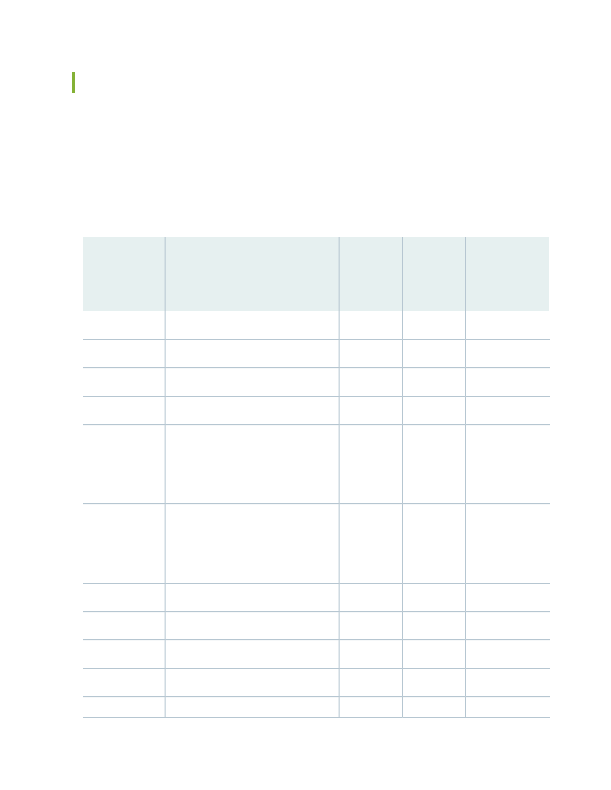
Line Card Model and Version Compatibility in an EX8200 Switch
Twelve line cards are available for EX8200 switches. The extra-scale line card models, identified by the
letters ES at the end of the model names, provide larger IPv4 and IPv6 route table than the non-extra-scale
models to store more unicast routes.
Table 36 on page 84 shows the model numbers, names of the line cards, the Junos OS release in which
the models were released, the release in which support on EX8200 Virtual Chassis was introduced, and
the release in which Virtual Chassis port (VCP) support was introduced for ports on the line card.
Table 36: Line Card Models by Junos OS Release
Support on
First
Junos OS
ReleaseNameModel Number
EX8200
Virtual
Chassis
EX8200 Virtual
Chassis Port
(VCP) Support
10.4R110.4R19.4R18-port SFP+ line cardEX8200-8XS
84
EX8200-2XS-40P
EX8200-2XS-40T
SFP+ line card
SFP+ line card
11.4R111.4R111.1R18-port SFP+ line card, extra-scaleEX8200-8XS-ES
Not supported11.1R110.3R140-port SFP+ line cardEX8200-40XS
Not supported11.4R111.4R140-port SFP+ line card, extra-scaleEX8200-40XS-ES
11.4R111.2R140-port PoE+ with 4-port SFP and 2-port
11.4R111.2R140-port RJ-45 with 4-port SFP and 2-port
11.4R1
NOTE: VCPs
supported on SFP+
transceivers only
11.4R1
NOTE: VCPs
supported on SFP+
transceivers only
Not supported11.4R111.2R148-port PoE+ 20 Gbps line cardEX8200-48PL
Not supported11.4R111.2R148-port RJ-45 20 Gbps line cardEX8200-48TL
Not supported10.4R19.4R148-port RJ-45 line cardEX8200-48T
Not supported11.4R111.1R148-port RJ-45 line card, extra-scaleEX8200-48T-ES
Not supported10.4R19.4R148-port SFP line cardEX8200-48F
Page 85

Table 36: Line Card Models by Junos OS Release (continued)
Support on
First
Junos OS
ReleaseNameModel Number
EX8200
Virtual
Chassis
EX8200 Virtual
Chassis Port
(VCP) Support
Not supported11.4R111.1R148-port SFP line card, extra-scaleEX8200-48F-ES
Table 37 on page 85 shows the model numbers, associated hardware revisions, and the required Junos OS
release for the EX8200 line cards that are shipped after August 7, 2015.
Table 37: EX8200 Line Cards, Hardware Revision, and Junos OS Release
Required Junos OS
ReleaseHardware RevisionModel Number
85
750-036593 REV12 or laterEX8200-40XS-ES
750-047322 REV03 or laterEX8200-48F-ES
750-047323 REV03 or laterEX8200-8XS-ES
750-047324 REV03 or laterEX8200-48T-ES
750-046751 REV06 or laterEX8200-40XS
750-047327 REV03 or laterEX8200-48T
750-047326 REV03 or laterEX8200-8XS
750-047325 REV03 or laterEX8200-48F
For the line cards listed in
this table to be operational,
the EX8200 switch must be
running one of the following
Junos OS releases:
12.3R10-S1
•
13.2X50
•
13.2X51
•
14.1X53 or later
•
Ensure that all of the line cards in a switch are supported in the Junos OS release that you want to use.
Page 86

NOTE: We recommend that you do not install extra-scale line card models and non-extra-scale
g020507
Ejector levers
SFP+ ports
Captive screw
Line card
LEDs
models in the same switch or Virtual Chassis. If you install extra-scale line cards in a switch or
Virtual Chassis that has non-extra-scale models installed, the IPv4 and IPv6 route table sizes
default to those of the non-extra-scale models and you will not get the benefit of the increased
table sizes of the extra-scale models.
You will experience these decreased route table sizes in a Virtual Chassis even when the
non-extra-scale line cards are installed in one member switch and the extra-scale line cards are
installed in another member switch.
8-port SFP+ Line Card in an EX8200 Switch
86
IN THIS SECTION
Line Card Models | 87
Line Card Components | 87
The line cards in EX8200 switches combine a Packet Forwarding Engine and Ethernet interfaces on a single
assembly. They are field-replaceable units (FRUs) that can be installed in the line card slots on the front
of the switch chassis. The line cards are hot-insertable and hot-removable: You can remove and replace
them without powering off the switch or disrupting switch functions (see Figure 20 on page 86).
Figure 20: 8-port SFP+ Line Card
Page 87

NOTE: Figure 20 on page 86 shows a line card that has 2-in.-long ejector levers. An earlier
version of this line card has 4-in.-long ejector levers.
Line Card Models
Table 38 on page 87 shows the model numbers, descriptions of the line card models, the Junos OS release
in which the models were released, the release in which support on EX8200 Virtual Chassis was introduced,
and the release in which Virtual Chassis Port (VCP) support was introduced for ports on the line card.
Table 38: 8-port SFP+ Line Card Models
87
EX8200 Virtual
Chassis Port
(VCP) Support
10.4R110.4R19.4R1 or later8-port SFP+ line cardEX8200-8XS
11.4R111.4R111.1R1 or laterExtra-scale 8-port SFP+ line card
EX8200-8XS-ES
NOTE: The extra-scale model
provides larger IPv4 and IPv6
route table sizes than the
non-extra-scale models to store
more unicast routes.
Junos OS
Release
RequiredDescriptionModel
Support on
EX8200 Virtual
Chassis
NOTE: We recommend that you do not install extra-scale line card models and non-extra-scale
models in the same switch or Virtual Chassis. If you install extra-scale line cards in a switch or
Virtual Chassis that has non-extra-scale models installed, the IPv4 and IPv6 route table sizes
default to those of the non-extra-scale models and you will not get the benefit of the increased
table sizes of the extra-scale models.
You will experience these decreased route table sizes in a Virtual Chassis even when the
non-extra-scale line cards are installed in one member switch and the extra-scale line cards are
installed in another member switch.
Line Card Components
Both models of the 8-port SFP+ line card (see Figure 20 on page 86) have:
Page 88

Eight 10-gigabit SFP+ ports, which can house SFP+ transceivers
•
NOTE: The 10-Gigabit Ethernet ports on the 8-port SFP+ line cards are the only ports that
you can configure as Virtual Chassis port (VCP) links between EX8200 member switches in an
EX8200 Virtual Chassis. You cannot configure ports on any other EX8200 line cards—including
the 10-Gigabit Ethernet ports on the 40-port SFP+ line cards—as VCPs. See Setting a 10-Gigabit
Ethernet Port as a Virtual Chassis Port in an EX8200 Virtual Chassis (CLI Procedure).
Eight dust covers preinstalled in the network ports
•
Line card status LEDs—Two status LEDs labeled ON and ST that indicate the online and status information
•
for the line card. See “Line Card LEDs in an EX8200 Switch” on page 105.
Network port LEDs—Two LEDs per network port that indicate the link/activity and status of each port.
•
See Network Port LEDs in an EX8200 Switch.
88
SEE ALSO
SFP+ Direct Attach Copper Cables for EX Series Switches | 129
40-port SFP+ Line Card in an EX8200 Switch
IN THIS SECTION
Line Card Models | 89
Line Card Components | 90
Line Card Ports | 90
The line cards in EX8200 switches combine a Packet Forwarding Engine and Ethernet interfaces on a single
assembly. They are field-replaceable units (FRUs) that can be installed in the line card slots on the front
of the switch chassis. The line cards are hot-insertable and hot-removable: You can remove and replace
them without powering off the switch or disrupting switch functions. See Figure 21 on page 89.
Page 89

Figure 21: 40-port SFP+ Line Card
20 21 22 23 24
25 26 27 28 29
10 11 12 13 14
15 16 17 18 19
0 1 2 3 4
5 6 7 8 9
30 31 32 33 34
35 36 37 38 39
EX8200-40XS
g020900
Line card LEDs
Ejector lever
Ejector lever
Network ports
Captive screw
Line Card Models
Table 39 on page 89 shows the model numbers, description of the line card models, the Junos OS release
in which the line card was released, the release in which support on EX8200 Virtual Chassis was introduced,
and the release in which Virtual Chassis Port (VCP) support was introduced for ports on the line card.
89
Table 39: 40-port SFP+ Line Card Models
EX8200-40XS-ES
card
NOTE: The extra-scale model
provides larger IPv4 and IPv6
route table sizes than the
non-extra-scale models to store
more unicast routes.
Junos OS
Release
RequiredDescriptionModel
Support on
EX8200
Virtual
Chassis
EX8200 Virtual
Chassis Port
(VCP) Support
Not supported11.1R110.3R1 or later40-port SFP+ line cardEX8200-40XS
Not supported11.4R111.4R1 or laterExtra-scale 40-port SFP+ line
Page 90

NOTE: We recommend that you do not install extra-scale line card models and non-extra-scale
models in the same switch or Virtual Chassis. If you install extra-scale line cards in a switch or
Virtual Chassis that has non-extra-scale models installed, the IPv4 and IPv6 route table sizes
default to those of the non-extra-scale models and you will not get the benefit of the increased
table sizes of the extra-scale models.
You will experience these decreased route table sizes in a Virtual Chassis even when the
non-extra-scale line cards are installed in one member switch and the extra-scale line cards are
installed in another member switch.
Line Card Components
Both models of the 40-port SFP+ line card (see Figure 21 on page 89) have:
40 oversubscribed 10-gigabit SFP+ ports, which can house SFP+ or SFP transceivers
•
90
40 dust covers (shipped in an accessory bag)
•
Line card status LEDs—Two status LEDs labeled ON and ST that indicate the online and status information
•
for the line card. See “Line Card LEDs in an EX8200 Switch” on page 105.
Network port LEDs—Two LEDs per network port that indicate the link/activity and status of each port.
•
See Network Port LEDs in an EX8200 Switch.
Line Card Ports
The ports on the faceplate of the line card are numbered sequentially. The ports are divided into eight
groups, with each group comprising five ports (see Figure 22 on page 91). Table 40 on page 90 shows the
port numbers on an EX8200-40XS line card and the port groups for each set of ports.
Table 40: Port Numbers and Port Groups on a 40-port SFP+ Line Card
Group NumberPort Number
00 through 4
15 through 9
210 through 14
315 through 19
420 through 24
Page 91
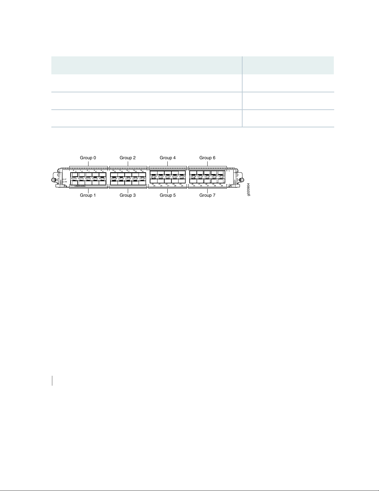
Table 40: Port Numbers and Port Groups on a 40-port SFP+ Line Card (continued)
Group 0 Group 2 Group 4 Group 6
Group 1 Group 3 Group 5 Group 7
g020904
Group NumberPort Number
525 through 29
630 through 34
735 through 39
Figure 22: Port Numbering and Port Groups on a 40-port SFP+ Line Card
91
The ports in each port group share 10 gigabits of bandwidth. Thus, you can transmit up to 10 gigabits of
traffic through a port group without packet drop.
The oversubscription ratios for different port groups can differ from one another; the ratios depend on
the amount of traffic being transmitted through a port group.
For more information about using these ports:
To understand how traffic is handled by oversubscribed ports, see Understanding CoS Queues on EX8200
•
Line Cards That Include Oversubscribed Ports.
To understand how CoS queues are handled on these line cards, see Understanding CoS Queues on EX8200
•
Line Cards That Include Oversubscribed Ports.
To see how to configure a different scheduler map for the ports in a group, see Defining CoS Schedulers
•
and Scheduler Maps (CLI Procedure).
SEE ALSO
Troubleshooting CoS Schedulers on a 40-port SFP+ Line Card in an EX8200 Switch
Page 92

EX8200-2XS-40P Line Card
g021054
PoE
Line card LEDs
RJ-45
ports
SFP
ports
(40-43)
SFP+
ports
(44,45)
EX8200-2XS-40P
IN THIS SECTION
Line Card Models | 92
Line Card Components | 93
Line Card Ports | 93
The line cards in EX8200 switches combine a Packet Forwarding Engine and Ethernet interfaces on a single
assembly. They are field-replaceable units (FRUs) that can be installed in the line card slots on the front
of the switch chassis. The line cards are hot-insertable and hot-removable: You can remove and replace
them without powering off the switch or disrupting switch functions.
92
The EX8200-2XS-40P (40-port PoE+ with 4-port SFP and 2-port SFP+) line card offers maximum port
density for the access layer and SFP and SFP+ uplink ports for connection to the distribution layer (see
Figure 23 on page 92).
Figure 23: EX8200-2XS-40P Line Card
Line Card Models
Table 41 on page 93 shows the model number, description of the line card model, the Junos OS release
in which the model was released, the release in which support on EX8200 Virtual Chassis was introduced,
and the release in which Virtual Chassis Port (VCP) support was introduced for ports on the line card.
Page 93

Table 41: EX8200-2XS-40P Line Card Models
93
Junos OS
Release
RequiredDescriptionModel
EX8200-2XS-40P
4-port SFP and 2-port
SFP+ line card
Support on
EX8200 Virtual
Chassis
11.4R111.2R1 or later40-port PoE+ with
EX8200 Virtual Chassis
Port (VCP) Support
11.4R1
NOTE: VCPs supported on
SFP+ transceivers only
Line Card Components
The EX8200-2XS-40P line card (see Figure 23 on page 92) has:
40 oversubscribed RJ-45 ports (PoE-enabled or PoE+-enabled)
•
4 SFP uplink ports
•
2 SFP+ uplink ports
•
Six dust covers (shipped in an accessory bag)
•
Line card status LEDs—Three status LEDs labeled ON, ST, and PoE that indicate the online, status, and
•
Power over Ethernet (PoE) information for the line card. See “Line Card LEDs in an EX8200 Switch” on
page 105.
Network port LEDs—Two LEDs per network port that indicate the link/activity and status of each port.
•
See Network Port LEDs in an EX8200 Switch.
Line Card Ports
Table 42 on page 93 shows the port number, port type, and port throughput on an EX8200-2XS-40P line
card.
Table 42: Ports on the EX8200-2XS-40P Line Card
Additional InformationThroughputPort TypePort Number
0 through 11
12 through 39
Oversubscribed, RJ-45,
PoE+ enabled
Oversubscribed, RJ-45,
PoE enabled
10/100/1000
Gigabit Ethernet
10/100/1000
Gigabit Ethernet
Line rateSFP40 through 43
The first 12 RJ-45 ports (ports 0–11) are PoE+
enabled and support IEEE 802.3at.
The final 28 RJ-45 ports (ports 12–39) are PoE
enabled and support IEEE 802.3af.
Can be used as an uplink of 1-Gigabit Ethernet fiber
links in a link aggregation group (LAG).
Page 94

Table 42: Ports on the EX8200-2XS-40P Line Card (continued)
Additional InformationThroughputPort TypePort Number
94
Line rateSFP+44 and 45
Can be used as an uplink of 10-Gigabit Ethernet fiber
links in a link aggregation group (LAG).
The ports are divided into two port groups:
The RJ-45 ports 0–19 and SFP ports 40 and 41 form one port group.
•
The RJ-45 ports 20–39 and SFP ports 42 and 43 form another port group.
•
The ports in each group share 10 gigabits of bandwidth. The SFP ports operate at 1 gigabit bandwidth.
Thus, you can transmit up to 8 gigabits of traffic through a port group when the SFP ports are active and
up to 10 gigabits when the SFP ports are not active, without packet drop. The oversubscription ratios of
different port groups can differ from one another; the ratios depend on the amount of traffic being
transmitted through a port group.
For more information about using these ports:
To understand how traffic is handled by oversubscribed ports, see Understanding CoS Queues on EX8200
•
Line Cards That Include Oversubscribed Ports.
SEE ALSO
Understanding PoE on EX Series Switches
EX8200-2XS-40T Line Card
IN THIS SECTION
Line Card Models | 95
Line Card Components | 95
Line Card Ports | 96
The line cards in EX8200 switches combine a Packet Forwarding Engine and Ethernet interfaces on a single
assembly. They are field-replaceable units (FRUs) that can be installed in the line card slots on the front
Page 95

of the switch chassis. The line cards are hot-insertable and hot-removable: You can remove and replace
g021051
Line card LEDs
RJ-45
ports
SFP
ports
(40-43)
SFP+
ports
(44,45)
EX8200-2XS-40T
them without powering off the switch or disrupting switch functions.
The EX8200-2XS-40T (40-port RJ-45 with 4-port SFP and 2-port SFP+) line card offers maximum port
density for the access layer and SFP and SFP+ uplink ports for connection to the distribution layer (see
Figure 24 on page 95).
Figure 24: EX8200-2XS-40T Line Card
Line Card Models
95
Table 43 on page 95 shows the model number, description of the line card model, the Junos OS release
in which the model was released, the release in which support on EX8200 Virtual Chassis was introduced,
and the release in which Virtual Chassis Port (VCP) support was introduced for ports on the line card.
Table 43: EX8200-2XS-40T Line Card Models
Junos OS
Release
RequiredDescriptionModel
EX8200-2XS-40T
4-port SFP and 2-port
SFP+ line card
Support on
EX8200 Virtual
Chassis
11.4R111.2R1 or later40-port RJ-45 with
EX8200 Virtual Chassis
Port (VCP) Support
11.4R1
NOTE: VCPs supported on
SFP+ transceivers only
Line Card Components
The EX8200-2XS-40T line card (see Figure 24 on page 95) has:
40 oversubscribed RJ-45 ports
•
4 SFP uplink ports
•
2 SFP+ uplink ports
•
Six dust covers (shipped in an accessory bag)
•
Page 96

Line card status LEDs—Two status LEDs labeled ON and ST that indicate the online and status for the
•
line card. See “Line Card LEDs in an EX8200 Switch” on page 105.
Network port LEDs—Two LEDs per network port that indicate the link/activity and status of each port.
•
See Network Port LEDs in an EX8200 Switch.
Line Card Ports
Table 44 on page 96 shows the port number, port type, and port throughput on an EX8200-2XS-40T line
card.
Table 44: Ports on the EX8200-2XS-40T Line Card
Additional InformationThroughputPort TypePort Number
96
Oversubscribed, RJ-450 through 39
10/100/1000
Gigabit Ethernet
Line rateSFP40 through 43
Line rateSFP+44 and 45
Can be used as an uplink of 1-Gigabit Ethernet fiber
links in a link aggregation group (LAG).
Can be used as an uplink of 10-Gigabit Ethernet fiber
links in a link aggregation group (LAG).
The ports are divided into two port groups:
The RJ-45 ports 0–19 and SFP ports 40 and 41 form one port group.
•
The RJ-45 ports 20–39 and SFP ports 42 and 43 form another port group.
•
The ports in each group share 10 gigabits of bandwidth. The SFP ports operate at 1 gigabit bandwidth.
Thus, you can transmit up to 8 gigabits of traffic through a port group when the SFP ports are active and
up to 10 gigabits when the SFP ports are not active, without packet drop. The oversubscription ratios of
different port groups can differ from one another; the ratios depend on the amount of traffic being
transmitted through a port group.
Page 97
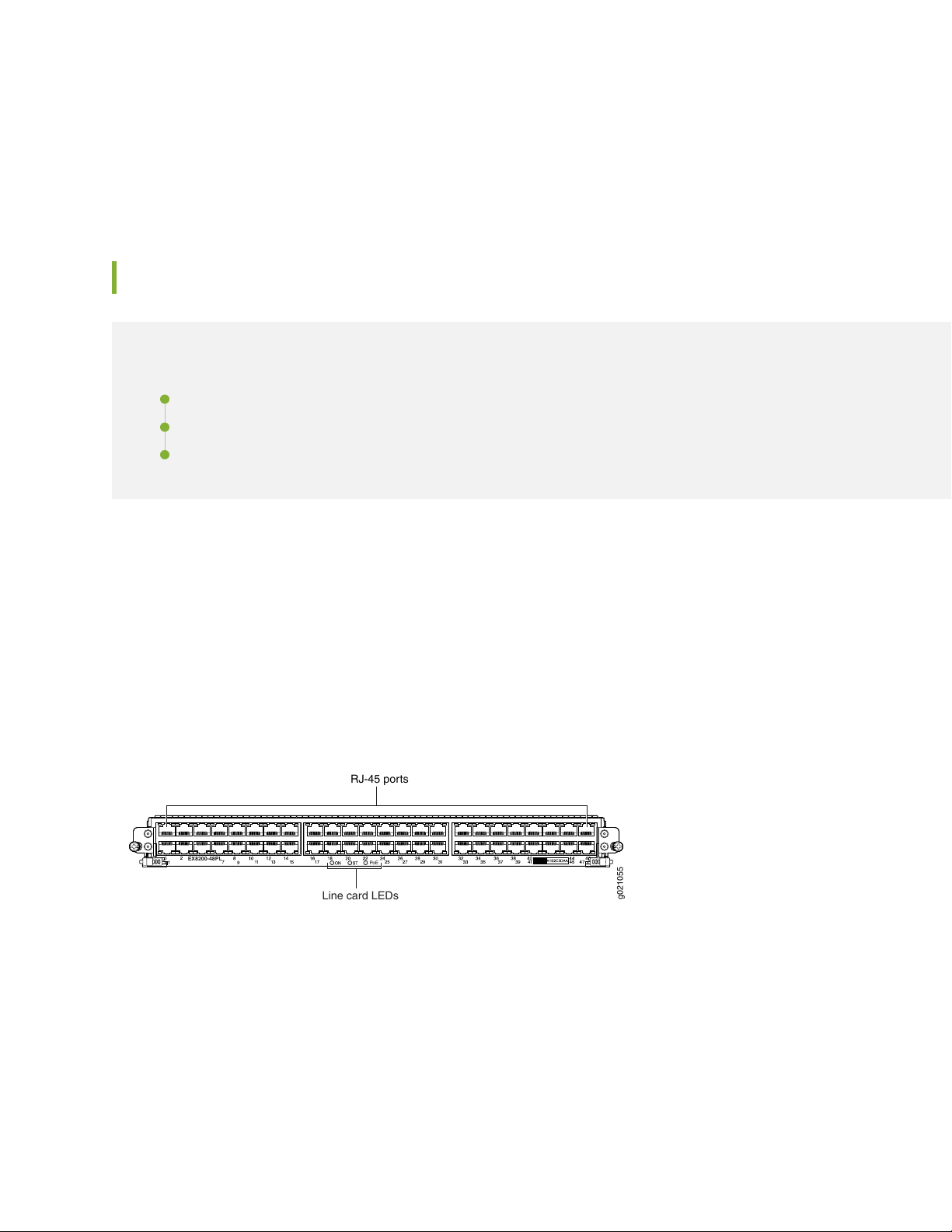
For more information about using these ports:
g021055
PoE
Line card LEDs
RJ-45 ports
EX8200-48PL
To understand how traffic is handled by oversubscribed ports, see Understanding CoS Queues on EX8200
•
Line Cards That Include Oversubscribed Ports.
EX8200-48PL Line Card
IN THIS SECTION
Line Card Models | 97
Line Card Components | 98
Line Card Ports | 98
97
The line cards in EX8200 switches combine a Packet Forwarding Engine and Ethernet interfaces on a single
assembly. They are field-replaceable units (FRUs) that can be installed in the line card slots on the front
of the switch chassis. The line cards are hot-insertable and hot-removable: You can remove and replace
them without powering off the switch or disrupting switch functions.
The EX8200-48PL (48-port PoE+ 20 Gbps) line card offers maximum port density for the access layer (see
Figure 25 on page 97) .
Figure 25: EX8200-48PL Line Card
Line Card Models
Table 45 on page 98 shows the model number, description of the line card model, the Junos OS release
in which the model was released, the release in which support on EX8200 Virtual Chassis was introduced,
and the release in which Virtual Chassis Port (VCP) support was introduced for ports on the line card.
Page 98

Table 45: EX8200-48PL Line Card Models
98
EX8200 Virtual Chassis
Port (VCP) Support
Not supported11.4R111.2R1 or later48-port PoE+ 20
EX8200-48PL
Gbps line card
Junos OS Release
RequiredDescriptionModel
Support on EX8200
Virtual Chassis
Line Card Components
The EX8200-48PL line card (see Figure 25 on page 97) has:
48 oversubscribed RJ-45 ports (PoE-enabled or PoE+-enabled)
•
Line card status LEDs—Three status LEDs labeled ON, ST, and Power over Ethernet (PoE) that indicate
•
the online, status, and PoE information for the line card. See “Line Card LEDs in an EX8200 Switch” on
page 105.
Network port LEDs—Two LEDS per network port that indicate the link/activity and status of each port.
•
See Network Port LEDs in an EX8200 Switch.
Line Card Ports
Table 46 on page 98 shows the port number, port type, and port throughput on an EX8200-48PL line
card.
Table 46: Ports on the EX8200-48PL Line Card
Additional InformationThroughputPort TypePort Number
0 through 11
12 through 47
Oversubscribed,
RJ-45,
PoE+-enabled
Oversubscribed,
RJ-45,
PoE-enabled
10/100/1000
Gigabit Ethernet
10/100/1000
Gigabit Ethernet
The first 12 RJ-45 ports (ports 0–11) are PoE+-enabled
(support IEEE 802.3at)
The final 36 RJ-45 ports (ports 12–47) are PoE-enabled
(support IEEE 802.3af)
The ports are divided into two port groups:
The ports 0 through 23 form one port group.
•
The ports 24 through 47 form another port group.
•
Page 99

The ports in each group share 10 gigabits of bandwidth. You can transmit up to 10 gigabits of traffic
through a port group without packet drop. The oversubscription ratios of different port groups can differ
from one another; the ratios depend on the amount of traffic being transmitted through a port group.
For more information about using these ports:
To understand how traffic is handled by oversubscribed ports, see Understanding CoS Queues on EX8200
•
Line Cards That Include Oversubscribed Ports.
SEE ALSO
Understanding PoE on EX Series Switches
EX8200-48TL Line Card
99
IN THIS SECTION
Line Card Models | 100
Line Card Components | 100
Line Card Ports | 100
The line cards in EX8200 switches combine a Packet Forwarding Engine and Ethernet interfaces on a single
assembly. They are field-replaceable units (FRUs) that can be installed in the line card slots on the front
of the switch chassis. The line cards are hot-insertable and hot-removable: You can remove and replace
them without powering off the switch or disrupting switch functions.
The EX8200-48TL (48-port RJ-45 20 Gbps) line card offers maximum port density for the access layer
(see Figure 26 on page 100).
Page 100
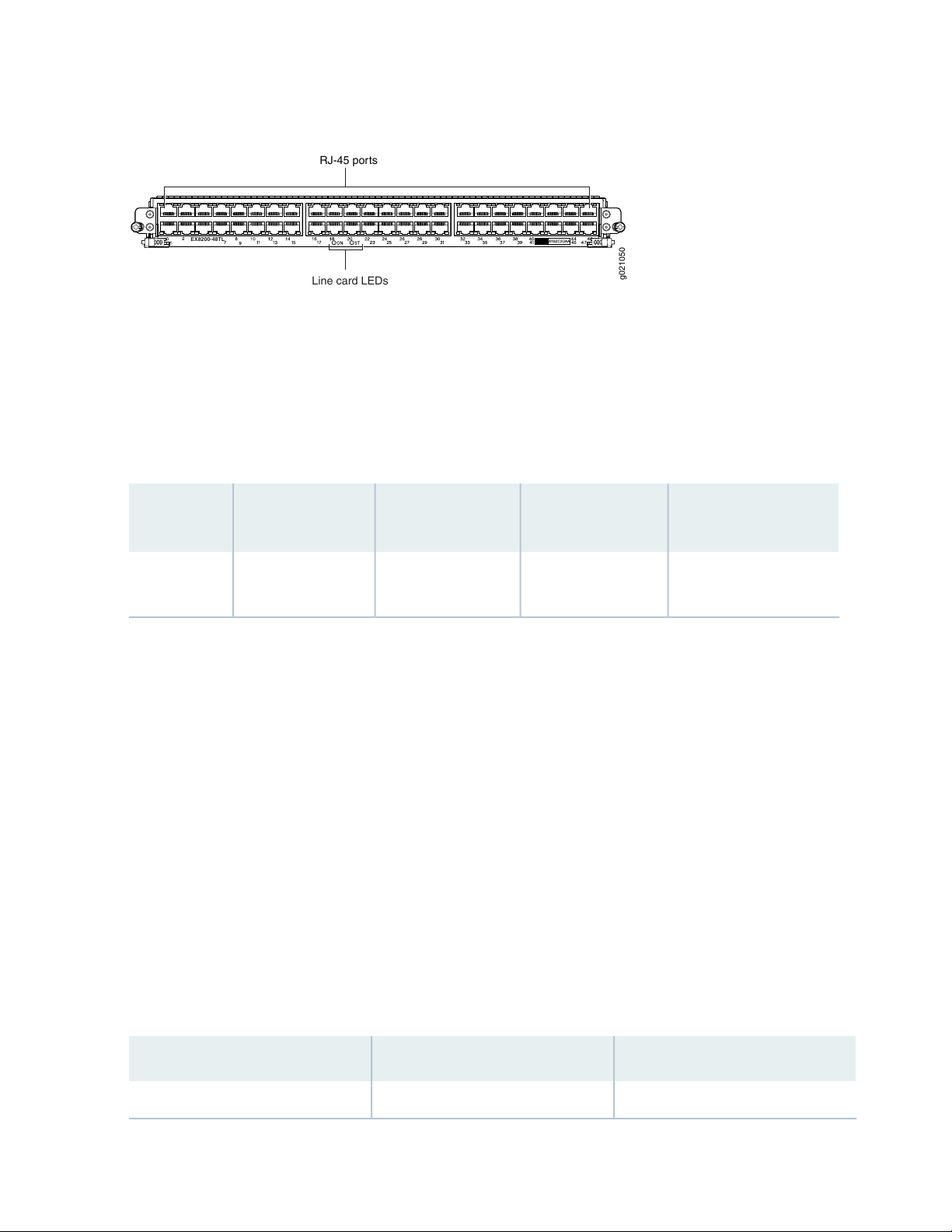
Figure 26: EX8200-48TL Line Card
g021050
EX8200-48TL
Line card LEDs
RJ-45 ports
Line Card Models
Table 47 on page 100 shows the model number, description of the line card model, the Junos OS release
in which the model was released, the release in which support on EX8200 Virtual Chassis was introduced,
and the release in which Virtual Chassis Port (VCP) support was introduced for ports on the line card.
Table 47: EX8200-40TL Line Card Models
100
EX8200 Virtual Chassis
Port (VCP) Support
Not supported11.4R111.2R1 or later48-port RJ-45 20
EX8200-40TL
Gbps line card
Junos OS Release
RequiredDescriptionModel
Support on EX8200
Virtual Chassis
Line Card Components
The EX8200-40TL line card (see Figure 26 on page 100) has:
40 oversubscribed RJ-45 ports
•
Line card status LEDs—Two status LEDs labeled ON and ST that indicate the online and status information
•
for the line card. See “Line Card LEDs in an EX8200 Switch” on page 105.
Network port LEDs—Two LEDs per network port that indicate the link/activity and status of each port.
•
See Network Port LEDs in an EX8200 Switch.
Line Card Ports
Table 48 on page 100 shows the port number, port type, and port throughput on an EX8200-48TL line
card.
Table 48: Ports on the EX8200-48PL Line Card
ThroughputPort TypePort Number
10/100/1000 Gigabit EthernetOversubscribed, RJ-450 through 47
 Loading...