

Juniper EX4500-40F-FB, EX4500-40F-DC-C, EX4500-40F-VC1-FB, EX4500-40F-VC1-BF, EX4500-40F-VC1-DC Complete Hardware Manual
...Page 1

Complete Hardware Guide for EX4500 Ethernet
Switches
Modified: 2015-06-23
Revision 13
Copyright © 2015, Juniper Networks, Inc.
Page 2

Juniper Networks, Inc.
1133 Innovation Way
Sunnyvale, California 94089
USA
408-745-2000
www.juniper.net
Juniper Networks, Junos, Steel-Belted Radius, NetScreen, and ScreenOS are registered trademarks of Juniper Networks, Inc. in the United
States and other countries. The Juniper Networks Logo, the Junos logo, and JunosE are trademarks of Juniper Networks, Inc. All other
trademarks, service marks, registered trademarks, or registered service marks are the property of their respective owners.
Juniper Networks assumes no responsibility for any inaccuracies in this document. Juniper Networks reserves the right to change, modify,
transfer, or otherwise revise this publication without notice.
Complete Hardware Guide for EX4500 Ethernet Switches
Copyright © 2015, Juniper Networks, Inc.
All rights reserved.
Revision History
July 2014—Revision 13
March 2014—Revision 12
January 2013—Revision 11
September 2012—Revision 10
September 2012—Revision 9
March 2012—Revision 8
November 2011—Revision 7
September 2011—Revision 6
July 2011—Revision 5
March 2011—Revision 4
December 2010—Revision 3
August 2010—Revision 2
May 2010—Revision 1
The information in this document is current as of the date on the title page.
YEAR 2000 NOTICE
Juniper Networks hardware and software products are Year 2000 compliant. Junos OS has no known time-related limitations through the
year 2038. However, the NTP application is known to have some difficulty in the year 2036.
SOFTWARE LICENSE
The terms and conditions for using this software aredescribed in the software license contained in the acknowledgment to your purchase
order or, to the extent applicable, to any reseller agreement or end-user purchase agreement executed between you and Juniper Networks.
By using this software, you indicate that you understand and agree to be bound by those terms and conditions.
Generally speaking, the software license restricts the manner in which you are permitted to use the software and may contain prohibitions
against certain uses. The software license may state conditions under which the license is automatically terminated. You should consult
the license for further details.
For complete product documentation, please see the Juniper NetworksWeb site at www.juniper.net/techpubs.
END USER LICENSE AGREEMENT
The Juniper Networks product that is the subject of this technical documentation consists of (or is intended for use with) Juniper Networks
software. Use of such software is subject tothe terms and conditions of the End User License Agreement (“EULA”) posted at
http://www.juniper.net/support/eula.html. By downloading, installing or using such software, you agree to the terms and conditions of
that EULA.
Copyright © 2015, Juniper Networks, Inc.ii
Page 3

Table of Contents
About the Documentation . . . . . . . . . . . . . . . . . . . . . . . . . . . . . . . . . . . . . . . . . . xv
Junos OS Documentation and Release Notes . . . . . . . . . . . . . . . . . . . . . . . . . xv
Documentation Conventions . . . . . . . . . . . . . . . . . . . . . . . . . . . . . . . . . . . . . . xv
Documentation Feedback . . . . . . . . . . . . . . . . . . . . . . . . . . . . . . . . . . . . . . . . xvii
Requesting Technical Support . . . . . . . . . . . . . . . . . . . . . . . . . . . . . . . . . . . . xvii
Self-Help Online Tools and Resources . . . . . . . . . . . . . . . . . . . . . . . . . . xviii
Opening a Case with JTAC . . . . . . . . . . . . . . . . . . . . . . . . . . . . . . . . . . . . xviii
Part 1 Switch and Components Overview and Specifications
Chapter 1 EX4500 Switch Overview . . . . . . . . . . . . . . . . . . . . . . . . . . . . . . . . . . . . . . . . . . . 3
EX4500 Switches Hardware Overview . . . . . . . . . . . . . . . . . . . . . . . . . . . . . . . . . . . 3
Software . . . . . . . . . . . . . . . . . . . . . . . . . . . . . . . . . . . . . . . . . . . . . . . . . . . . . . . 3
EX4500 Switches First View . . . . . . . . . . . . . . . . . . . . . . . . . . . . . . . . . . . . . . . 4
Intraconnect Module and Virtual Chassis Module . . . . . . . . . . . . . . . . . . . . . . . 5
Virtual Chassis . . . . . . . . . . . . . . . . . . . . . . . . . . . . . . . . . . . . . . . . . . . . . . . . . . 6
Uplink Modules . . . . . . . . . . . . . . . . . . . . . . . . . . . . . . . . . . . . . . . . . . . . . . . . . . 6
Power Supplies . . . . . . . . . . . . . . . . . . . . . . . . . . . . . . . . . . . . . . . . . . . . . . . . . . 6
EX4500 Switch Models . . . . . . . . . . . . . . . . . . . . . . . . . . . . . . . . . . . . . . . . . . . . . . . 7
Identifying EX4500 Switch Models . . . . . . . . . . . . . . . . . . . . . . . . . . . . . . . . . . . . . 10
Chassis Physical Specifications for EX4500 Switches . . . . . . . . . . . . . . . . . . . . . . 11
Front Panel of an EX4500 Switch . . . . . . . . . . . . . . . . . . . . . . . . . . . . . . . . . . . . . . 12
Rear Panel of an EX4500 Switch . . . . . . . . . . . . . . . . . . . . . . . . . . . . . . . . . . . . . . . 13
EX4500 Switch Hardware and CLI Terminology Mapping . . . . . . . . . . . . . . . . . . . 15
Chapter 2 Component Descriptions . . . . . . . . . . . . . . . . . . . . . . . . . . . . . . . . . . . . . . . . . . . 17
LCD Panel in EX4500 Switches . . . . . . . . . . . . . . . . . . . . . . . . . . . . . . . . . . . . . . . . 17
LCD Panel Modes . . . . . . . . . . . . . . . . . . . . . . . . . . . . . . . . . . . . . . . . . . . . . . . . 18
LCD Panel Menus . . . . . . . . . . . . . . . . . . . . . . . . . . . . . . . . . . . . . . . . . . . . . . . . 19
Chassis Status LEDs in EX4500 Switches . . . . . . . . . . . . . . . . . . . . . . . . . . . . . . . 22
Field-Replaceable Units in EX4500 Switches . . . . . . . . . . . . . . . . . . . . . . . . . . . . 23
Network Port and Uplink Module Port LEDs in EX4500 Switches . . . . . . . . . . . . . 24
Management Port LEDs in EX4500 Switches . . . . . . . . . . . . . . . . . . . . . . . . . . . . 26
AC Power Supply in EX4500 Switches . . . . . . . . . . . . . . . . . . . . . . . . . . . . . . . . . . 27
AC Power Supply LEDs in EX4500 Switches . . . . . . . . . . . . . . . . . . . . . . . . . . . . . 29
DC Power Supply in EX4500 Switches . . . . . . . . . . . . . . . . . . . . . . . . . . . . . . . . . . 30
DC Power Supply LEDs in EX4500 Switches . . . . . . . . . . . . . . . . . . . . . . . . . . . . . 32
Cooling System and Airflow in an EX4500 Switch . . . . . . . . . . . . . . . . . . . . . . . . . 32
Fan Tray . . . . . . . . . . . . . . . . . . . . . . . . . . . . . . . . . . . . . . . . . . . . . . . . . . . . . . . 33
Airfow Direction in EX4500 Switch Models . . . . . . . . . . . . . . . . . . . . . . . . . . . 33
Front-to-Back Airflow . . . . . . . . . . . . . . . . . . . . . . . . . . . . . . . . . . . . . . . . . . . . 34
iiiCopyright © 2015, Juniper Networks, Inc.
Page 4

Complete Hardware Guide for EX4500 Ethernet Switches
Back-to-Front Airflow . . . . . . . . . . . . . . . . . . . . . . . . . . . . . . . . . . . . . . . . . . . . 34
Uplink Modules in EX4500 Switches . . . . . . . . . . . . . . . . . . . . . . . . . . . . . . . . . . . 36
Intraconnect Module in EX4500 Switches . . . . . . . . . . . . . . . . . . . . . . . . . . . . . . . 38
Virtual Chassis Module in EX4500 Switches . . . . . . . . . . . . . . . . . . . . . . . . . . . . . 39
Chapter 3 Component Specifications . . . . . . . . . . . . . . . . . . . . . . . . . . . . . . . . . . . . . . . . . 41
USB Port Specifications for an EX Series Switch . . . . . . . . . . . . . . . . . . . . . . . . . . . 41
Console Port Connector Pinout Information for an EX Series Switch . . . . . . . . . . 42
RJ-45 to DB-9 Serial Port Adapter Pinout Information for a Switch . . . . . . . . . . . 43
Management Port Connector Pinout Information for an EX4500 Switch . . . . . . . 44
NetworkPort and Uplink ModulePort ConnectorPinout Information for EX4500
Switches . . . . . . . . . . . . . . . . . . . . . . . . . . . . . . . . . . . . . . . . . . . . . . . . . . . . . . 45
Virtual Chassis Ports Connector Pinout Information for EX4500 Switches . . . . . 46
Pluggable Transceivers Supported on EX4500 Switches . . . . . . . . . . . . . . . . . . . 49
SFP+ Direct Attach Cables for EX Series Switches . . . . . . . . . . . . . . . . . . . . . . . . . 67
Cable Specifications . . . . . . . . . . . . . . . . . . . . . . . . . . . . . . . . . . . . . . . . . . . . . 68
Standards Supported by These Cables . . . . . . . . . . . . . . . . . . . . . . . . . . . . . . 72
Grounding Cable and Lug Specifications for EX4500 Switches . . . . . . . . . . . . . . . 72
Part 2 Planning for Switch Installation
Chapter 4 Site Preparation . . . . . . . . . . . . . . . . . . . . . . . . . . . . . . . . . . . . . . . . . . . . . . . . . . . 77
Site Preparation Checklist for EX4500 Switches . . . . . . . . . . . . . . . . . . . . . . . . . . 77
General Site Guidelines . . . . . . . . . . . . . . . . . . . . . . . . . . . . . . . . . . . . . . . . . . . . . . 78
Site Electrical Wiring Guidelines . . . . . . . . . . . . . . . . . . . . . . . . . . . . . . . . . . . . . . . 79
Environmental Requirements and Specifications for EX Series Switches . . . . . . . 81
Chapter 5 Rack and Cabinet Requirements . . . . . . . . . . . . . . . . . . . . . . . . . . . . . . . . . . . . 85
Rack Requirements for EX4500 Switches . . . . . . . . . . . . . . . . . . . . . . . . . . . . . . . 85
Cabinet Requirements for EX4500 Switches . . . . . . . . . . . . . . . . . . . . . . . . . . . . . 86
Clearance Requirements for Airflow and Hardware Maintenance for EX4500
Switches . . . . . . . . . . . . . . . . . . . . . . . . . . . . . . . . . . . . . . . . . . . . . . . . . . . . . . 87
Chapter 6 Cable Requirements . . . . . . . . . . . . . . . . . . . . . . . . . . . . . . . . . . . . . . . . . . . . . . . 91
Network Cable Specifications for EX4500 Switches . . . . . . . . . . . . . . . . . . . . . . . 91
Understanding EX Series Switches Fiber-Optic Cable Signal Loss, Attenuation,
and Dispersion . . . . . . . . . . . . . . . . . . . . . . . . . . . . . . . . . . . . . . . . . . . . . . . . . . 91
Signal Loss in Multimode and Single-Mode Fiber-Optic Cable . . . . . . . . . . . 92
Attenuation and Dispersion in Fiber-Optic Cable . . . . . . . . . . . . . . . . . . . . . . 92
Chapter 7 Planning Power Requirements . . . . . . . . . . . . . . . . . . . . . . . . . . . . . . . . . . . . . . 95
AC Power Supply Specifications for EX4500 Switches . . . . . . . . . . . . . . . . . . . . . 95
DC Power Specifications for EX4500 Switches . . . . . . . . . . . . . . . . . . . . . . . . . . . 96
AC Power Cord Specifications for an EX4500 Switch . . . . . . . . . . . . . . . . . . . . . . 96
Calculating the EX Series Switch Fiber-Optic Cable Power Budget . . . . . . . . . . 100
Calculating the EX Series Switch Fiber-Optic Cable Power Margin . . . . . . . . . . . 100
Copyright © 2015, Juniper Networks, Inc.iv
Page 5

Table of Contents
Chapter 8 Planning the Virtual Chassis . . . . . . . . . . . . . . . . . . . . . . . . . . . . . . . . . . . . . . . 103
Understanding EX4200, EX4500, and EX4550 Virtual Chassis Hardware
Configurations . . . . . . . . . . . . . . . . . . . . . . . . . . . . . . . . . . . . . . . . . . . . . . . . . 103
Ports Used to Interconnect Virtual Chassis Members . . . . . . . . . . . . . . . . . . 103
Number of Switches, Required Software Releases, and Member RolesThat
You Configure in the Virtual Chassis . . . . . . . . . . . . . . . . . . . . . . . . . . . . 104
Virtual Chassis Module . . . . . . . . . . . . . . . . . . . . . . . . . . . . . . . . . . . . . . . . . . 105
Switch Role and Member ID on the LCD Panel . . . . . . . . . . . . . . . . . . . . . . . 106
Planning EX4200, EX4500, and EX4550 Virtual Chassis . . . . . . . . . . . . . . . . . . 106
Part 3 Installing and Connecting the Switch and Switch Components
Chapter 9 Installing the Switch . . . . . . . . . . . . . . . . . . . . . . . . . . . . . . . . . . . . . . . . . . . . . . . 111
Installing and Connecting an EX4500 Switch . . . . . . . . . . . . . . . . . . . . . . . . . . . . . 111
Unpacking an EX4500 Switch . . . . . . . . . . . . . . . . . . . . . . . . . . . . . . . . . . . . . . . . 112
Parts Inventory (Packing List) for an EX4500 Switch . . . . . . . . . . . . . . . . . . . . . . 112
Mounting an EX4500 Switch . . . . . . . . . . . . . . . . . . . . . . . . . . . . . . . . . . . . . . . . . 114
Mounting an EX4500 Switch on Two Posts in a Rack or Cabinet . . . . . . . . . . . . . 114
Mounting an EX4500 Switch on Four Posts in a Rack or Cabinet . . . . . . . . . . . . . 116
Mounting an EX4500 Switch in a Recessed Position in a Rack or Cabinet . . . . . 120
Chapter 10 Installing Switch Components . . . . . . . . . . . . . . . . . . . . . . . . . . . . . . . . . . . . . . 121
Installing and Removing EX4500 Switch Hardware Components . . . . . . . . . . . . 121
Installing an AC Power Supply in an EX4500 Switch . . . . . . . . . . . . . . . . . . . . . . 122
Installing a DC Power Supply in an EX4500 Switch . . . . . . . . . . . . . . . . . . . . . . . 124
Installing a Fan Tray in an EX4500 Switch . . . . . . . . . . . . . . . . . . . . . . . . . . . . . . . 125
Installing an Uplink Module in an EX4500 Switch . . . . . . . . . . . . . . . . . . . . . . . . . 127
Installing an Intraconnect Module in an EX4500 Switch . . . . . . . . . . . . . . . . . . . 129
Installing a Virtual Chassis Module in an EX4500 Switch . . . . . . . . . . . . . . . . . . . 131
Connecting a Virtual Chassis Cable to an EX4500 Switch . . . . . . . . . . . . . . . . . . 133
Installing a Transceiver in an EX Series Switch . . . . . . . . . . . . . . . . . . . . . . . . . . . 134
Chapter 11 Connecting the Switch . . . . . . . . . . . . . . . . . . . . . . . . . . . . . . . . . . . . . . . . . . . . 137
Connecting Earth Ground to an EX Series Switch . . . . . . . . . . . . . . . . . . . . . . . . . 137
Parts and Tools Required for Connecting an EX Series Switch to Earth
Ground . . . . . . . . . . . . . . . . . . . . . . . . . . . . . . . . . . . . . . . . . . . . . . . . . . . 138
Special Instructions to Follow Before Connecting Earth Ground to a
Switch . . . . . . . . . . . . . . . . . . . . . . . . . . . . . . . . . . . . . . . . . . . . . . . . . . . . 140
Connecting Earth Ground to an EX Series Switch . . . . . . . . . . . . . . . . . . . . . 142
Connecting AC Power to an EX4500 Switch . . . . . . . . . . . . . . . . . . . . . . . . . . . . . 143
Connecting DC Power to an EX4500 Switch . . . . . . . . . . . . . . . . . . . . . . . . . . . . . 145
Connecting a Switch to a Network for Out-of-Band Management . . . . . . . . . . . 149
Connecting a Switch to a Management Console . . . . . . . . . . . . . . . . . . . . . . . . . 150
Connecting a Fiber-Optic Cable to a Switch . . . . . . . . . . . . . . . . . . . . . . . . . . . . . 152
Chapter 12 Performing Initial Configuration . . . . . . . . . . . . . . . . . . . . . . . . . . . . . . . . . . . . 155
EX4500 Default Configuration . . . . . . . . . . . . . . . . . . . . . . . . . . . . . . . . . . . . . . . . 155
Connecting and Configuring an EX Series Switch (CLI Procedure) . . . . . . . . . . . . 161
Connecting and Configuring an EX Series Switch (J-Web Procedure) . . . . . . . . . 164
vCopyright © 2015, Juniper Networks, Inc.
Page 6

Complete Hardware Guide for EX4500 Ethernet Switches
Part 4 Removing the Switch and Switch Components
Chapter 13 Removing the Switch . . . . . . . . . . . . . . . . . . . . . . . . . . . . . . . . . . . . . . . . . . . . . . 171
Powering Off an EX4500 Switch . . . . . . . . . . . . . . . . . . . . . . . . . . . . . . . . . . . . . . . 171
Removing an EX4500 Switch from a Rack or Cabinet . . . . . . . . . . . . . . . . . . . . . 173
Chapter 14 Removing Switch Components . . . . . . . . . . . . . . . . . . . . . . . . . . . . . . . . . . . . . 175
Installing and Removing EX4500 Switch Hardware Components . . . . . . . . . . . . 175
Removing an AC Power Supply from an EX4500 Switch . . . . . . . . . . . . . . . . . . . 176
Replacing Redundant AC Power Supplies in an EX4500 Switch Without
Disrupting Switch Functions . . . . . . . . . . . . . . . . . . . . . . . . . . . . . . . . . . . . . . 178
Replacing the Power Supply in the Top Slot . . . . . . . . . . . . . . . . . . . . . . . . . 180
Replacing the Power Supply in the Bottom Slot . . . . . . . . . . . . . . . . . . . . . . 182
Removing a DC Power Supply from an EX4500 Switch . . . . . . . . . . . . . . . . . . . . 183
Removing a Fan Tray from an EX4500 Switch . . . . . . . . . . . . . . . . . . . . . . . . . . . 184
Removing an Uplink Module from an EX4500 Switch . . . . . . . . . . . . . . . . . . . . . 186
Removing an Intraconnect Module from an EX4500 Switch . . . . . . . . . . . . . . . . 188
Removing a Virtual Chassis Module from an EX4500 Switch . . . . . . . . . . . . . . . 190
Disconnecting a Virtual Chassis Cable from an EX4500 Switch . . . . . . . . . . . . . 192
Disconnecting a Fiber-Optic Cable from a Switch . . . . . . . . . . . . . . . . . . . . . . . . 194
Removing a Transceiver from a Switch . . . . . . . . . . . . . . . . . . . . . . . . . . . . . . . . . 195
Part 5 Switch and Component Maintenance
Chapter 15 Routine Maintenance . . . . . . . . . . . . . . . . . . . . . . . . . . . . . . . . . . . . . . . . . . . . . 201
Maintaining Fiber-Optic Cables in Switches . . . . . . . . . . . . . . . . . . . . . . . . . . . . . 201
Part 6 Troubleshooting Switch Issues
Chapter 16 Troubleshooting Switch Issues . . . . . . . . . . . . . . . . . . . . . . . . . . . . . . . . . . . . 205
Troubleshooting the Boot Process on EX4500 Switches . . . . . . . . . . . . . . . . . . 205
Part 7 Returning Hardware
Chapter 17 Returning the Switch or Switch Components . . . . . . . . . . . . . . . . . . . . . . . . 209
Returning an EX4500 Switch or Component for Repair or Replacement . . . . . . 209
Locating the Serial Number on an EX4500 Switch or Component . . . . . . . . . . . 210
Listing the Switch and Components Details with the CLI . . . . . . . . . . . . . . . 210
Locating the Chassis Serial Number ID Label on an EX4500 Switch . . . . . . . 211
Locating the Serial Number ID Labels on FRUs in an EX4500 Switch . . . . . . 211
Contacting Customer Support to Obtain Return Materials Authorization for
Switches . . . . . . . . . . . . . . . . . . . . . . . . . . . . . . . . . . . . . . . . . . . . . . . . . . . . . . 213
Packing an EX4500 Switch or Component for Shipping . . . . . . . . . . . . . . . . . . . 215
Packing an EX4500 Switch for Shipping . . . . . . . . . . . . . . . . . . . . . . . . . . . . 216
Packing EX4500 Switch Components for Shipping . . . . . . . . . . . . . . . . . . . . 217
Part 8 Safety Information
Chapter 18 General Safety Information . . . . . . . . . . . . . . . . . . . . . . . . . . . . . . . . . . . . . . . . 221
General Safety Guidelines and Warnings . . . . . . . . . . . . . . . . . . . . . . . . . . . . . . . . 221
Definitions of Safety Warning Levels . . . . . . . . . . . . . . . . . . . . . . . . . . . . . . . . . . . 222
Copyright © 2015, Juniper Networks, Inc.vi
Page 7

Table of Contents
Fire Safety Requirements . . . . . . . . . . . . . . . . . . . . . . . . . . . . . . . . . . . . . . . . . . . . 224
Qualified Personnel Warning . . . . . . . . . . . . . . . . . . . . . . . . . . . . . . . . . . . . . . . . . 225
Warning Statement for Norway and Sweden . . . . . . . . . . . . . . . . . . . . . . . . . . . . 226
Chapter 19 Radiation and Laser Warnings . . . . . . . . . . . . . . . . . . . . . . . . . . . . . . . . . . . . . 227
Laser and LED Safety Guidelines and Warnings for Switches . . . . . . . . . . . . . . . 227
General Laser Safety Guidelines . . . . . . . . . . . . . . . . . . . . . . . . . . . . . . . . . . . 227
Class 1 Laser Product Warning . . . . . . . . . . . . . . . . . . . . . . . . . . . . . . . . . . . . 228
Class 1 LED Product Warning . . . . . . . . . . . . . . . . . . . . . . . . . . . . . . . . . . . . . 228
Laser Beam Warning . . . . . . . . . . . . . . . . . . . . . . . . . . . . . . . . . . . . . . . . . . . . 229
Radiation from Open Port Apertures Warning . . . . . . . . . . . . . . . . . . . . . . . . . . . 230
Chapter 20 Installation and Maintenance Safety Information . . . . . . . . . . . . . . . . . . . . 233
Installation Instructions Warning . . . . . . . . . . . . . . . . . . . . . . . . . . . . . . . . . . . . . . 233
Chassis Lifting Guidelines for EX4500 Switches . . . . . . . . . . . . . . . . . . . . . . . . . 235
Ramp Warning . . . . . . . . . . . . . . . . . . . . . . . . . . . . . . . . . . . . . . . . . . . . . . . . . . . . 236
Rack-Mounting and Cabinet-Mounting Warnings . . . . . . . . . . . . . . . . . . . . . . . . 236
Grounded Equipment Warning . . . . . . . . . . . . . . . . . . . . . . . . . . . . . . . . . . . . . . . . 241
Maintenance and Operational Safety Guidelines and Warnings . . . . . . . . . . . . . 242
Battery Handling Warning . . . . . . . . . . . . . . . . . . . . . . . . . . . . . . . . . . . . . . . 242
Jewelry Removal Warning . . . . . . . . . . . . . . . . . . . . . . . . . . . . . . . . . . . . . . . . 243
Lightning Activity Warning . . . . . . . . . . . . . . . . . . . . . . . . . . . . . . . . . . . . . . . 244
Operating Temperature Warning . . . . . . . . . . . . . . . . . . . . . . . . . . . . . . . . . . 245
Product Disposal Warning . . . . . . . . . . . . . . . . . . . . . . . . . . . . . . . . . . . . . . . 246
Chapter 21 Power and Electrical Safety Information . . . . . . . . . . . . . . . . . . . . . . . . . . . . 249
General Electrical Safety Guidelines and Warnings . . . . . . . . . . . . . . . . . . . . . . . 249
Prevention of Electrostatic Discharge Damage . . . . . . . . . . . . . . . . . . . . . . . . . . 250
AC Power Electrical Safety Guidelines . . . . . . . . . . . . . . . . . . . . . . . . . . . . . . . . . 252
AC Power Disconnection Warning . . . . . . . . . . . . . . . . . . . . . . . . . . . . . . . . . . . . . 254
DC Power Electrical Safety Guidelines . . . . . . . . . . . . . . . . . . . . . . . . . . . . . . . . . 255
DC Power Disconnection Warning . . . . . . . . . . . . . . . . . . . . . . . . . . . . . . . . . . . . . 257
DC Power Grounding Requirements and Warning . . . . . . . . . . . . . . . . . . . . . . . . 259
DC Power Wiring Sequence Warning . . . . . . . . . . . . . . . . . . . . . . . . . . . . . . . . . . 260
DC Power Wiring Terminations Warning . . . . . . . . . . . . . . . . . . . . . . . . . . . . . . . . 262
Multiple Power Supplies Disconnection Warning . . . . . . . . . . . . . . . . . . . . . . . . . 263
TN Power Warning . . . . . . . . . . . . . . . . . . . . . . . . . . . . . . . . . . . . . . . . . . . . . . . . . 264
Action to Take After an Electrical Accident . . . . . . . . . . . . . . . . . . . . . . . . . . . . . . 264
Part 9 Compliance Information
Chapter 22 Compliance Information . . . . . . . . . . . . . . . . . . . . . . . . . . . . . . . . . . . . . . . . . . 269
Agency Approvals for EX Series Switches . . . . . . . . . . . . . . . . . . . . . . . . . . . . . . 269
Compliance Statements for EMC Requirements for EX Series Switches . . . . . . 270
Canada . . . . . . . . . . . . . . . . . . . . . . . . . . . . . . . . . . . . . . . . . . . . . . . . . . . . . . 270
European Community . . . . . . . . . . . . . . . . . . . . . . . . . . . . . . . . . . . . . . . . . . . 271
Israel . . . . . . . . . . . . . . . . . . . . . . . . . . . . . . . . . . . . . . . . . . . . . . . . . . . . . . . . . 271
Japan . . . . . . . . . . . . . . . . . . . . . . . . . . . . . . . . . . . . . . . . . . . . . . . . . . . . . . . . 271
Korea . . . . . . . . . . . . . . . . . . . . . . . . . . . . . . . . . . . . . . . . . . . . . . . . . . . . . . . . 272
United States . . . . . . . . . . . . . . . . . . . . . . . . . . . . . . . . . . . . . . . . . . . . . . . . . . 272
viiCopyright © 2015, Juniper Networks, Inc.
Page 8

Complete Hardware Guide for EX4500 Ethernet Switches
FCC Part 15 Statement . . . . . . . . . . . . . . . . . . . . . . . . . . . . . . . . . . . . . . . . . . 272
Nonregulatory Environmental Standards . . . . . . . . . . . . . . . . . . . . . . . . . . . . 273
Compliance Statements for Acoustic Noise for EX Series Switches . . . . . . . . . . 274
Declaration of Conformity for EX4500 Switches . . . . . . . . . . . . . . . . . . . . . . . . . 274
Copyright © 2015, Juniper Networks, Inc.viii
Page 9

List of Figures
Part 1 Switch and Components Overview and Specifications
Chapter 1 EX4500 Switch Overview . . . . . . . . . . . . . . . . . . . . . . . . . . . . . . . . . . . . . . . . . . . 3
Figure 1: EX4500 Switch Front . . . . . . . . . . . . . . . . . . . . . . . . . . . . . . . . . . . . . . . . . . 4
Figure 2: EX4500 Switch Rear with Intraconnect Module Installed . . . . . . . . . . . . . 4
Figure 3: EX4500 Switch Rear with Virtual Chassis Module Installed . . . . . . . . . . . 5
Figure 4: EX4500 Switch Front Panel . . . . . . . . . . . . . . . . . . . . . . . . . . . . . . . . . . . 12
Figure 5: Label Identifying EX4500 Switches that Support DCB . . . . . . . . . . . . . . 13
Figure 6: EX4500 Switch Rear Panel with an Intraconnect Module Installed . . . . 14
Figure 7: EX4500 Switch Rear Panel with a Virtual Chassis Module Installed . . . . 14
Chapter 2 Component Descriptions . . . . . . . . . . . . . . . . . . . . . . . . . . . . . . . . . . . . . . . . . . . 17
Figure 8: LCD Panel in EX4500 Switches . . . . . . . . . . . . . . . . . . . . . . . . . . . . . . . . . 17
Figure 9: Chassis Status LEDs in an EX4500 Switch . . . . . . . . . . . . . . . . . . . . . . . 22
Figure 10: Network Port LEDs . . . . . . . . . . . . . . . . . . . . . . . . . . . . . . . . . . . . . . . . . . 24
Figure 11: Uplink Module Port LEDs . . . . . . . . . . . . . . . . . . . . . . . . . . . . . . . . . . . . . 25
Figure 12: LEDs on the Management Port on an EX4500 Switch . . . . . . . . . . . . . . 26
Figure 13: AC Power Supply . . . . . . . . . . . . . . . . . . . . . . . . . . . . . . . . . . . . . . . . . . . 28
Figure 14: Power Cord Retainer for an AC Power Supply . . . . . . . . . . . . . . . . . . . . 28
Figure 15: AC Power Supply LEDs in EX4500 Switches . . . . . . . . . . . . . . . . . . . . . 29
Figure 16: DC Power Supply . . . . . . . . . . . . . . . . . . . . . . . . . . . . . . . . . . . . . . . . . . . 31
Figure 17: DC Power Supply LED in EX4500 Switches . . . . . . . . . . . . . . . . . . . . . . 32
Figure 18: Fan Tray Used in an EX4500 Switch . . . . . . . . . . . . . . . . . . . . . . . . . . . . 33
Figure 19: Front-to-Back Airflow Through the EX4500 Switch Chassis . . . . . . . . 34
Figure 20: Back-to-Front Airflow Through the EX4500 Switch Chassis . . . . . . . . 35
Figure 21: Uplink Module Slots in an EX4500 Switch . . . . . . . . . . . . . . . . . . . . . . . 36
Figure 22: SFP+ Uplink Module . . . . . . . . . . . . . . . . . . . . . . . . . . . . . . . . . . . . . . . . 37
Figure 23: Intraconnect Module . . . . . . . . . . . . . . . . . . . . . . . . . . . . . . . . . . . . . . . . 38
Figure 24: Virtual Chassis Module . . . . . . . . . . . . . . . . . . . . . . . . . . . . . . . . . . . . . . 39
Figure 25: Virtual Chassis Module LEDs . . . . . . . . . . . . . . . . . . . . . . . . . . . . . . . . . 40
Chapter 3 Component Specifications . . . . . . . . . . . . . . . . . . . . . . . . . . . . . . . . . . . . . . . . . 41
Figure 26: SFP+ Direct Attach Cables for EX Series Switches . . . . . . . . . . . . . . . . 68
Part 2 Planning for Switch Installation
Chapter 5 Rack and Cabinet Requirements . . . . . . . . . . . . . . . . . . . . . . . . . . . . . . . . . . . . 85
Figure 27: Front-to-Back Airflow Through the EX4500-40F-FB Switch
Chassis . . . . . . . . . . . . . . . . . . . . . . . . . . . . . . . . . . . . . . . . . . . . . . . . . . . . . . . 88
Figure 28: Back-to-Front Airflow Through the EX4500-40F-BF Switch
Chassis . . . . . . . . . . . . . . . . . . . . . . . . . . . . . . . . . . . . . . . . . . . . . . . . . . . . . . . 88
ixCopyright © 2015, Juniper Networks, Inc.
Page 10

Complete Hardware Guide for EX4500 Ethernet Switches
Figure 29: Clearance Requirements for Airflow and Hardware Maintenance for
an EX4500 Switch Chassis . . . . . . . . . . . . . . . . . . . . . . . . . . . . . . . . . . . . . . . 88
Part 3 Installing and Connecting the Switch and Switch Components
Chapter 9 Installing the Switch . . . . . . . . . . . . . . . . . . . . . . . . . . . . . . . . . . . . . . . . . . . . . . . 111
Figure 30: Attaching the Mounting Bracket Along the Front of the Switch . . . . . . 115
Figure 31: Mounting the Switch on Two Posts in a Rack . . . . . . . . . . . . . . . . . . . . . 116
Figure 32: Attaching the Front-Mounting Bracket to the Switch Chassis . . . . . . . 118
Figure 33: Mounting the Switch on the Front Posts in a Rack . . . . . . . . . . . . . . . . 119
Figure 34: Sliding the Rear Mounting-Blades to the Rear of a Four-Post Rack . . . 119
Chapter 10 Installing Switch Components . . . . . . . . . . . . . . . . . . . . . . . . . . . . . . . . . . . . . . 121
Figure 35: Installing a Power Supply in an EX4500 Switch . . . . . . . . . . . . . . . . . . 123
Figure 36: Installing a DC Power Supply in an EX4500 Switch . . . . . . . . . . . . . . . 125
Figure 37: Installing a Fan Tray in an EX4500 Switch . . . . . . . . . . . . . . . . . . . . . . 126
Figure 38: Uplink Module Slots in an EX4500 Switch . . . . . . . . . . . . . . . . . . . . . . 127
Figure 39: Installing an Uplink Module in an EX4500 Switch . . . . . . . . . . . . . . . . 128
Figure 40: Installing an Intraconnect Module in an EX4500 Switch . . . . . . . . . . . 131
Figure 41: Installing the Virtual Chassis Module in an EX4500 Switch . . . . . . . . . 133
Figure 42: Connecting a Virtual Chassis Cable to a Dedicated VCP on a Virtual
Chassis Module . . . . . . . . . . . . . . . . . . . . . . . . . . . . . . . . . . . . . . . . . . . . . . . . 134
Figure 43: Installing a Transceiver in an EX Series Switch . . . . . . . . . . . . . . . . . . . 136
Chapter 11 Connecting the Switch . . . . . . . . . . . . . . . . . . . . . . . . . . . . . . . . . . . . . . . . . . . . 137
Figure 44: Connecting the Grounding Lug to a Switch Mounted on Four Posts of
a Rack . . . . . . . . . . . . . . . . . . . . . . . . . . . . . . . . . . . . . . . . . . . . . . . . . . . . . . . . 141
Figure 45: Connecting a Grounding Cable to an EX Series Switch . . . . . . . . . . . . 142
Figure 46: Power Cord Retainer in an AC Power Supply . . . . . . . . . . . . . . . . . . . . 144
Figure 47: Connecting the Power Supply Cord to an EX4500 Switch . . . . . . . . . 145
Figure 48: Remove Plastic Cover from Terminal Block . . . . . . . . . . . . . . . . . . . . . 147
Figure 49: Connecting the Power Supply Cables to an EX4500 Switch . . . . . . . 148
Figure 50: Install Plastic Cover on Terminal Block . . . . . . . . . . . . . . . . . . . . . . . . . 148
Figure 51: Ethernet Cable Connector . . . . . . . . . . . . . . . . . . . . . . . . . . . . . . . . . . . 149
Figure 52: Connecting a Switch to a Network for Out-of-Band Management . . . 150
Figure 53: Ethernet Cable Connector . . . . . . . . . . . . . . . . . . . . . . . . . . . . . . . . . . . 151
Figure 54: Connecting a Switch to a Management Console Through a Console
Server . . . . . . . . . . . . . . . . . . . . . . . . . . . . . . . . . . . . . . . . . . . . . . . . . . . . . . . . 152
Figure 55: Connecting a Switch Directly to a Management Console . . . . . . . . . . 152
Figure 56: Connecting a Fiber-Optic Cable to an Optical Transceiver Installed in
a Switch . . . . . . . . . . . . . . . . . . . . . . . . . . . . . . . . . . . . . . . . . . . . . . . . . . . . . . 153
Chapter 12 Performing Initial Configuration . . . . . . . . . . . . . . . . . . . . . . . . . . . . . . . . . . . . 155
Figure 57: LCD Panel in an EX3200, EX4200, EX4500, EX4550, or EX8200
Switch . . . . . . . . . . . . . . . . . . . . . . . . . . . . . . . . . . . . . . . . . . . . . . . . . . . . . . . 165
Figure 58: LCD Panel in an EX4300 Switch . . . . . . . . . . . . . . . . . . . . . . . . . . . . . . 165
Part 4 Removing the Switch and Switch Components
Chapter 14 Removing Switch Components . . . . . . . . . . . . . . . . . . . . . . . . . . . . . . . . . . . . . 175
Figure 59: Removing a Power Supply from an EX4500 Switch . . . . . . . . . . . . . . 178
Copyright © 2015, Juniper Networks, Inc.x
Page 11

List of Figures
Figure 60: Verify Green Power Supply LEDs for Normal Operation . . . . . . . . . . . 180
Figure 61: Removing an AC Power Supply from an EX4500 Switch . . . . . . . . . . . 181
Figure 62: Sliding a Replacement Power Supply into the EX4500 Switch . . . . . . 181
Figure 63: Connecting the Replacement Power Supply Cord . . . . . . . . . . . . . . . . 182
Figure 64: Removing a DC Power Supply from an EX4500 Switch . . . . . . . . . . . 184
Figure 65: Removing a Fan Tray from an EX4500 Switch . . . . . . . . . . . . . . . . . . 186
Figure 66: Removing an Uplink Module from an EX4500 Switch . . . . . . . . . . . . . 187
Figure 67: Removing an Intraconnect Module from an EX4500 Switch . . . . . . . 189
Figure 68: Removing the Virtual Chassis Module from an EX4500 Switch . . . . . 192
Figure 69: Disconnecting a Virtual Chassis Cable from a Dedicated VCP on a
Virtual Chassis Module . . . . . . . . . . . . . . . . . . . . . . . . . . . . . . . . . . . . . . . . . . 193
Figure 70: Removing a Transceiver from a Switch . . . . . . . . . . . . . . . . . . . . . . . . . 196
Part 7 Returning Hardware
Chapter 17 Returning the Switch or Switch Components . . . . . . . . . . . . . . . . . . . . . . . . 209
Figure 71: Location of the Serial Number ID Label on an EX4500 Switch . . . . . . . 211
Figure 72: Location of the Serial Number ID Label on an AC Power Supply Used
in an EX4500 Switch . . . . . . . . . . . . . . . . . . . . . . . . . . . . . . . . . . . . . . . . . . . . 212
Figure 73: Location of the Serial Number ID Label on the Fan Tray Used in an
EX4500 Switch . . . . . . . . . . . . . . . . . . . . . . . . . . . . . . . . . . . . . . . . . . . . . . . . 212
Figure 74: Location of the Serial Number ID Label on the Virtual Chassis Module
Used in an EX4500 Switch . . . . . . . . . . . . . . . . . . . . . . . . . . . . . . . . . . . . . . . 213
Part 8 Safety Information
Chapter 21 Power and Electrical Safety Information . . . . . . . . . . . . . . . . . . . . . . . . . . . . 249
Figure 75: Placing a Component into an Antistatic Bag . . . . . . . . . . . . . . . . . . . . 251
Part 9 Compliance Information
Chapter 22 Compliance Information . . . . . . . . . . . . . . . . . . . . . . . . . . . . . . . . . . . . . . . . . . 269
Figure 76: Declaration of Conformity for the EU . . . . . . . . . . . . . . . . . . . . . . . . . . 275
Figure 77: Suppliers Declaration of Conformity for Australia and New
Zealand . . . . . . . . . . . . . . . . . . . . . . . . . . . . . . . . . . . . . . . . . . . . . . . . . . . . . . 276
xiCopyright © 2015, Juniper Networks, Inc.
Page 12

Complete Hardware Guide for EX4500 Ethernet Switches
Copyright © 2015, Juniper Networks, Inc.xii
Page 13

List of Tables
About the Documentation . . . . . . . . . . . . . . . . . . . . . . . . . . . . . . . . . . . . . . . . . . xv
Table 1: Notice Icons . . . . . . . . . . . . . . . . . . . . . . . . . . . . . . . . . . . . . . . . . . . . . . . . . xvi
Table 2: Text and Syntax Conventions . . . . . . . . . . . . . . . . . . . . . . . . . . . . . . . . . . xvi
Part 1 Switch and Components Overview and Specifications
Chapter 1 EX4500 Switch Overview . . . . . . . . . . . . . . . . . . . . . . . . . . . . . . . . . . . . . . . . . . . 3
Table 3: EX4500 Switch Models, Components, and Supported Junos OS
Table 4: Physical Specifications of the EX4500 Switch Chassis . . . . . . . . . . . . . . . 11
Table 5: CLI Equivalents of Terms Used in Documentation for EX4500
Chapter 2 Component Descriptions . . . . . . . . . . . . . . . . . . . . . . . . . . . . . . . . . . . . . . . . . . . 17
Table 6: LCD Panel Menu Options in EX4500 Switches . . . . . . . . . . . . . . . . . . . . . 19
Table 7: Chassis Status LEDs in an EX4500 Switch . . . . . . . . . . . . . . . . . . . . . . . . 22
Table 8: Link/ActivityLED on Network Ports and Uplink Module Ports in EX4500
Table 9: Status LED on Network Ports and Uplink Module Ports in EX4500
Table 10: Link/Activity LED on the Management Port on an EX4500 Switch . . . . 27
Table 11: Status LED on the Management Port on an EX4500 Switch . . . . . . . . . . 27
Table 12: Power Supply LED on EX4500 Switches . . . . . . . . . . . . . . . . . . . . . . . . . 30
Table 13: DC Power Supply LED on EX4500 Switches . . . . . . . . . . . . . . . . . . . . . . 32
Table 14: Airflow Direction in EX4500 Switch Models . . . . . . . . . . . . . . . . . . . . . . 33
Table 15: Uplink Module Status LED . . . . . . . . . . . . . . . . . . . . . . . . . . . . . . . . . . . . 37
Table 16: Intraconnect Module Status LED . . . . . . . . . . . . . . . . . . . . . . . . . . . . . . . 38
Table 17: Virtual Chassis Module LEDs . . . . . . . . . . . . . . . . . . . . . . . . . . . . . . . . . . 40
Chapter 3 Component Specifications . . . . . . . . . . . . . . . . . . . . . . . . . . . . . . . . . . . . . . . . . 41
Table 18: EX Series Switches Console Port Connector Pinout Information . . . . . . 42
Table 19: RJ-45 to DB-9 Serial Port Adapter Pinout Information . . . . . . . . . . . . . . 44
Table 20: Management Port Connector Pinout Information for EX4500
Table 21: Network Port and Uplink Module Port Connector Pinout Information
Table 22: Virtual Chassis Ports (VCPs) Connector Pinout Information . . . . . . . . . 46
Table 23: Optical interface Support and Copper Interface Support for Gigabit
Table 24: Optical interface Support for Gigabit Ethernet SFP+ Transceivers in
Release . . . . . . . . . . . . . . . . . . . . . . . . . . . . . . . . . . . . . . . . . . . . . . . . . . . . . . . . 7
Switches . . . . . . . . . . . . . . . . . . . . . . . . . . . . . . . . . . . . . . . . . . . . . . . . . . . . . . . 15
Switches . . . . . . . . . . . . . . . . . . . . . . . . . . . . . . . . . . . . . . . . . . . . . . . . . . . . . . 25
Switches . . . . . . . . . . . . . . . . . . . . . . . . . . . . . . . . . . . . . . . . . . . . . . . . . . . . . . 26
Switches . . . . . . . . . . . . . . . . . . . . . . . . . . . . . . . . . . . . . . . . . . . . . . . . . . . . . . 44
for EX4500 Switches . . . . . . . . . . . . . . . . . . . . . . . . . . . . . . . . . . . . . . . . . . . . 45
Ethernet SFP Transceivers in EX4500 Switches . . . . . . . . . . . . . . . . . . . . . . . 51
EX4500 Switches . . . . . . . . . . . . . . . . . . . . . . . . . . . . . . . . . . . . . . . . . . . . . . . 62
xiiiCopyright © 2015, Juniper Networks, Inc.
Page 14

Complete Hardware Guide for EX4500 Ethernet Switches
Table 25: Software Support for SFP+ Passive Direct Attach Cables for EX Series
Switches . . . . . . . . . . . . . . . . . . . . . . . . . . . . . . . . . . . . . . . . . . . . . . . . . . . . . . 68
Table 26: SFP+ Direct Attach Cable Specifications . . . . . . . . . . . . . . . . . . . . . . . . 70
Part 2 Planning for Switch Installation
Chapter 4 Site Preparation . . . . . . . . . . . . . . . . . . . . . . . . . . . . . . . . . . . . . . . . . . . . . . . . . . . 77
Table 27: Site Preparation Checklist . . . . . . . . . . . . . . . . . . . . . . . . . . . . . . . . . . . . . 77
Table 28: Site Electrical Wiring Guidelines . . . . . . . . . . . . . . . . . . . . . . . . . . . . . . . 80
Table 29: EX Series Switch Environmental Tolerances . . . . . . . . . . . . . . . . . . . . . . 82
Chapter 5 Rack and Cabinet Requirements . . . . . . . . . . . . . . . . . . . . . . . . . . . . . . . . . . . . 85
Table 30: Rack Requirements and Specifications for the Switch . . . . . . . . . . . . . 85
Table 31: Cabinet Requirements and Specifications for the Switch . . . . . . . . . . . . 87
Chapter 7 Planning Power Requirements . . . . . . . . . . . . . . . . . . . . . . . . . . . . . . . . . . . . . . 95
Table 32: AC Power Supply Specifications for an EX4500 Switch . . . . . . . . . . . . 95
Table 33: Power Specifications for the DC Power Supply Used in an EX4500
Switch . . . . . . . . . . . . . . . . . . . . . . . . . . . . . . . . . . . . . . . . . . . . . . . . . . . . . . . . 96
Table 34: AC Power Cord Specifications for an EX4500 Switch . . . . . . . . . . . . . . 97
Table 35: Estimated Values for Factors Causing Link Loss . . . . . . . . . . . . . . . . . . 101
Chapter 8 Planning the Virtual Chassis . . . . . . . . . . . . . . . . . . . . . . . . . . . . . . . . . . . . . . . 103
Table 36: Number of Switches and Switch Roles for an EX4200 Virtual Chassis,
per Junos OS Release . . . . . . . . . . . . . . . . . . . . . . . . . . . . . . . . . . . . . . . . . . . 104
Table 37: Number of Switches and Switch Roles for an EX4500 Virtual Chassis,
per Junos OS Release . . . . . . . . . . . . . . . . . . . . . . . . . . . . . . . . . . . . . . . . . . . 105
Table 38: Number of Switches and Switch Roles for an EX4550 Virtual Chassis,
per Junos OS Release . . . . . . . . . . . . . . . . . . . . . . . . . . . . . . . . . . . . . . . . . . . 105
Table 39: Number of Switches and Switch Roles for a Mixed EX4200, EX4500,
and EX4550 Virtual Chassis, per Junos OS Release . . . . . . . . . . . . . . . . . . . 105
Table 40: Virtual Chassis Components to Consider When Planning an EX4200,
EX4500, and EX4550 Virtual Chassis . . . . . . . . . . . . . . . . . . . . . . . . . . . . . . 106
Table 41: Cabling Requirements for a Virtual Chassis . . . . . . . . . . . . . . . . . . . . . . 107
Part 3 Installing and Connecting the Switch and Switch Components
Chapter 9 Installing the Switch . . . . . . . . . . . . . . . . . . . . . . . . . . . . . . . . . . . . . . . . . . . . . . . 111
Table 42: Inventory of Components Provided with an EX4500 Switch . . . . . . . . . 113
Chapter 11 Connecting the Switch . . . . . . . . . . . . . . . . . . . . . . . . . . . . . . . . . . . . . . . . . . . . 137
Table 43: Parts and Tools Required for Connecting an EX Series Switch to Earth
Ground . . . . . . . . . . . . . . . . . . . . . . . . . . . . . . . . . . . . . . . . . . . . . . . . . . . . . . . 138
Table 44: Special Instructions to Follow Before Connecting Earth Ground to a
Switch . . . . . . . . . . . . . . . . . . . . . . . . . . . . . . . . . . . . . . . . . . . . . . . . . . . . . . . 140
Copyright © 2015, Juniper Networks, Inc.xiv
Page 15

About the Documentation
•
Junos OS Documentation and Release Notes on page xv
•
Documentation Conventions on page xv
•
Documentation Feedback on page xvii
•
Requesting Technical Support on page xvii
Junos OS Documentation and Release Notes
For a list of related Junos OS documentation, see
http://www.juniper.net/techpubs/software/junos/.
If the information in the latest release notes differs from the information in the
documentation, follow the Junos OS Release Notes.
To obtain the most current version of all Juniper Networks®technical documentation,
see the product documentation page on the Juniper Networks website at
http://www.juniper.net/techpubs/.
Documentation Conventions
Table 1 on page xvi defines the notice icons used in this guide.
xvCopyright © 2015, Juniper Networks, Inc.
Page 16
Complete Hardware Guide for EX4500 Ethernet Switches
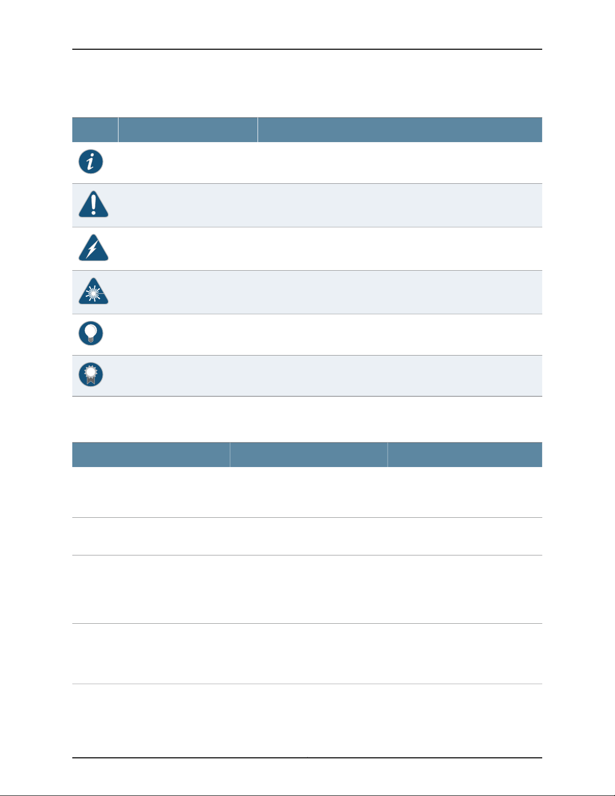
Table 1: Notice Icons
DescriptionMeaningIcon
Indicates important features or instructions.Informational note
Indicates a situation that might result in loss of data or hardware damage.Caution
Alerts you to the risk of personal injury or death.Warning
Alerts you to the risk of personal injury from a laser.Laser warning
Indicates helpful information.Tip
Table 2 on page xvi defines the text and syntax conventions used in this guide.
Table 2: Text and Syntax Conventions
Represents text that you type.Bold text like this
Fixed-width text like this
Italic text like this
Italic text like this
Represents output that appears on the
terminal screen.
•
Introduces or emphasizes important
new terms.
•
Identifies guide names.
•
Identifies RFC and Internet draft titles.
Represents variables (options for which
you substitute a value) in commands or
configuration statements.
Alerts you to a recommended use or implementation.Best practice
ExamplesDescriptionConvention
To enter configuration mode, type the
configure command:
user@host> configure
user@host> show chassis alarms
No alarms currently active
•
A policy term is a named structure
that defines match conditions and
actions.
•
Junos OS CLI User Guide
•
RFC 1997,BGP Communities Attribute
Configure the machine’s domain name:
[edit]
root@# set system domain-name
domain-name
Copyright © 2015, Juniper Networks, Inc.xvi
Page 17

Table 2: Text and Syntax Conventions (continued)
Text like this
Represents names of configuration
statements, commands, files, and
directories;configurationhierarchy levels;
or labels on routing platform
components.
About the Documentation
ExamplesDescriptionConvention
•
To configure a stub area, include the
stub statement at the [edit protocols
ospf area area-id] hierarchy level.
•
The console port is labeledCONSOLE.
stub <default-metric metric>;Encloses optional keywords or variables.< > (angle brackets)
| (pipe symbol)
# (pound sign)
[ ] (square brackets)
Indention and braces ( { } )
; (semicolon)
GUI Conventions
Bold text like this
Indicatesa choice between the mutually
exclusivekeywordsor variables on either
side of the symbol. The set of choices is
often enclosed in parentheses for clarity.
same line as the configuration statement
to which it applies.
Encloses a variable for which you can
substitute one or more values.
Identifies a level in the configuration
hierarchy.
Identifies a leaf statement at a
configuration hierarchy level.
Representsgraphicaluser interface(GUI)
items you click or select.
broadcast | multicast
(string1 | string2 | string3)
rsvp { # Required for dynamic MPLS onlyIndicates a comment specified on the
community name members [
community-ids ]
[edit]
routing-options {
static {
route default {
nexthop address;
retain;
}
}
}
•
In the Logical Interfaces box, select
All Interfaces.
•
To cancel the configuration, click
Cancel.
> (bold right angle bracket)
Documentation Feedback
We encourage you to provide feedback, comments, and suggestions so that we can
improve the documentation. You can provide feedback by using either of the following
methods:
Requesting Technical Support
Technicalproduct support is availablethrough the Juniper NetworksTechnical Assistance
Center (JTAC). If you are a customer with an active J-Care or Partner Support Service
Separates levels in a hierarchy of menu
selections.
In the configuration editor hierarchy,
select Protocols>Ospf.
xviiCopyright © 2015, Juniper Networks, Inc.
Page 18

Complete Hardware Guide for EX4500 Ethernet Switches
support contract, or are covered under warranty, and need post-sales technical support,
you can access our tools and resources online or open a case with JTAC.
•
JTAC policies—For a complete understanding of our JTAC procedures and policies,
review the JTAC User Guide located at
http://www.juniper.net/us/en/local/pdf/resource-guides/7100059-en.pdf.
•
Product warranties—For product warranty information, visit
http://www.juniper.net/support/warranty/.
•
JTAC hours of operation—The JTAC centers have resources available 24 hours a day,
7 days a week, 365 days a year.
Self-Help Online Tools and Resources
For quick and easy problem resolution, Juniper Networks has designed an online
self-service portal called the Customer Support Center (CSC) that provides you with the
following features:
•
Find CSC offerings: http://www.juniper.net/customers/support/
•
Search for known bugs: http://www2.juniper.net/kb/
•
Find product documentation: http://www.juniper.net/techpubs/
•
Find solutions and answer questions using our Knowledge Base: http://kb.juniper.net/
•
Download the latest versions of software and review release notes:
http://www.juniper.net/customers/csc/software/
•
Search technical bulletins for relevant hardware and software notifications:
http://kb.juniper.net/InfoCenter/
•
Join and participate in the Juniper Networks Community Forum:
http://www.juniper.net/company/communities/
•
Open a case online in the CSC Case Management tool: http://www.juniper.net/cm/
To verify serviceentitlement by product serial number,use our Serial Number Entitlement
(SNE) Tool: https://tools.juniper.net/SerialNumberEntitlementSearch/
Opening a Case with JTAC
You can open a case with JTAC on the Web or by telephone.
•
Use the Case Management tool in the CSC at http://www.juniper.net/cm/.
•
Call 1-888-314-JTAC (1-888-314-5822 toll-free in the USA, Canada, and Mexico).
For international or direct-dial options in countries without toll-free numbers, see
http://www.juniper.net/support/requesting-support.html.
Copyright © 2015, Juniper Networks, Inc.xviii
Page 19

PART 1
Switch and Components Overview and
Specifications
•
EX4500 Switch Overview on page 3
•
Component Descriptions on page 17
•
Component Specifications on page 41
1Copyright © 2015, Juniper Networks, Inc.
Page 20

Complete Hardware Guide for EX4500 Ethernet Switches
Copyright © 2015, Juniper Networks, Inc.2
Page 21

CHAPTER 1
EX4500 Switch Overview
•
EX4500 Switches Hardware Overview on page 3
•
EX4500 Switch Models on page 7
•
Identifying EX4500 Switch Models on page 10
•
Chassis Physical Specifications for EX4500 Switches on page 11
•
Front Panel of an EX4500 Switch on page 12
•
Rear Panel of an EX4500 Switch on page 13
•
EX4500 Switch Hardware and CLI Terminology Mapping on page 15
EX4500 Switches Hardware Overview
Juniper Networks EX4500 Ethernet Switches provide high-density 10-gigabit ports for
aggregation layerand data center top-of-rack deployments,and provideoptions for data
center optimized airflow (hot aisle/cold aisle). You can configure EX4500 switches in a
Virtual Chassis, or in a mixed Virtual Chassis with EX4200 switches or EX4550 switches
or both, in a total of up to 10 members.
Software
You can manage EX4500 switches using the same interfaces that you use for managing
other devices running Juniper Networks Junos operating system (Junos OS)—the
command-line interface (CLI) and the J-Web graphical interface.
•
Software on page 3
•
EX4500 Switches First View on page 4
•
Intraconnect Module and Virtual Chassis Module on page 5
•
Virtual Chassis on page 6
•
Uplink Modules on page 6
•
Power Supplies on page 6
Juniper Networks EX Series Ethernet Switches run Junos OS, which provides Layer 2 and
Layer 3 switching, routing, and security services. The same Junos OS code base that runs
on EX Series switches also runs on all Juniper Networks M Series, MX Series, and T Series
routers, and SRX Series Services Gateways. For information about installing software on
your switch, see Software Installation on EX Series Switches.
3Copyright © 2015, Juniper Networks, Inc.
Page 22
g020845
g020846
EX4500-LB
ST
0
1
Fan tray
AC power
supply
Intraconnect
module
Fan tray handle
Complete Hardware Guide for EX4500 Ethernet Switches
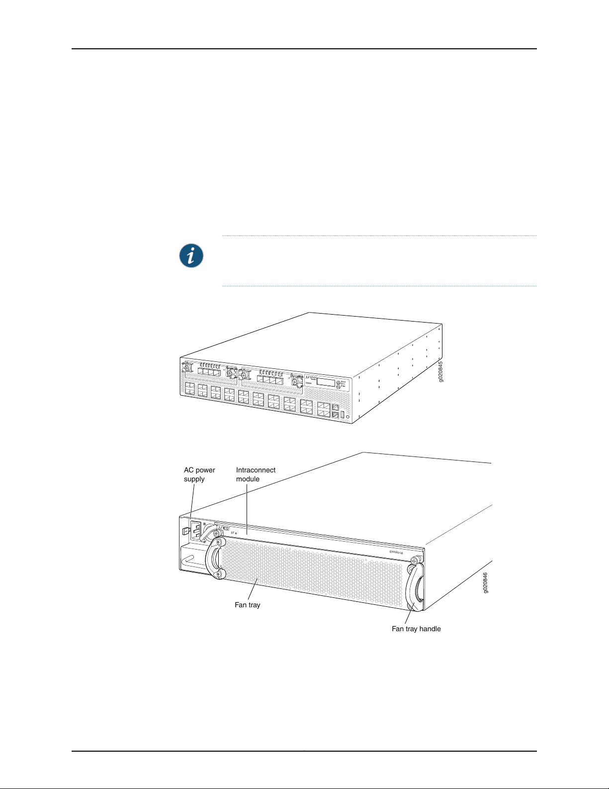
EX4500 Switches First View
EX4500 switches provide connectivity for high-density 10-Gigabit Ethernet data center
top-of-rack and aggregation deployments. Typically, EX4500 switches are used in data
centers where they can be positioned as the top device in a rack to provide connectivity
for all devices in the rack.
The EX4500 switch is 2 rack units (2 U) in size. Each EX4500 switch is designed to
optimize rack space utilization and cabling. See Figure 1 on page 4, Figure 2 on page 4,
and Figure 3 on page 5.
NOTE: The side of the switch where the networkports are locatedis the front
of the switch.
Figure 1: EX4500 Switch Front
Figure 2: EX4500 Switch Rear with Intraconnect Module Installed
Copyright © 2015, Juniper Networks, Inc.4
Page 23
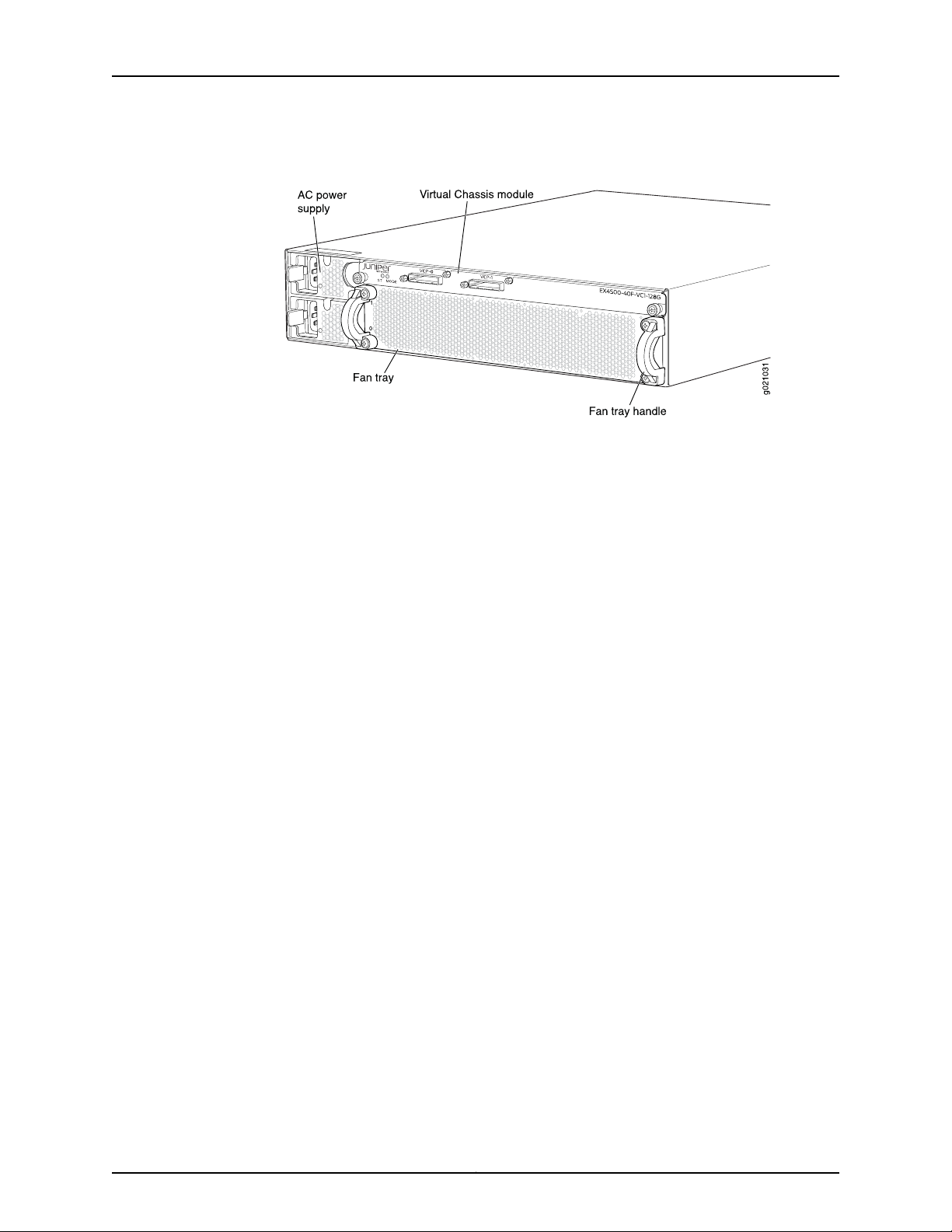
Chapter 1: EX4500 Switch Overview
Figure 3: EX4500 Switch Rear with Virtual Chassis Module Installed
EX4500 switches are availablein models with either front-toback airflowor back-to-front
airflow and hardware that either supports or does not support Data Center Bridging
(DCB), also known as Converged Enhanced Ethernet (CEE). See “EX4500 Switch Models”
on page 7. All eight models provide40 wire-speed10-gigabit small form-factorpluggable
(SFP+) network ports that can house either 1-Gigabit Ethernet transceivers or 10-Gigabit
Ethernet transceivers. All models support two optional high-speed uplink modules.
To provide carrier-class reliability, EX4500 switches include:
•
Dual redundant, load-sharingpower supplies that are hot-insertableand hot-removable
field-replaceable units.
•
An FRU fan tray with five fans. The switch remains operational if a single fan fails.
•
RedundantRouting Engines in a Virtual Chassis configuration. This redundancy enables
graceful Routing Engine switchover (GRES).
•
Junos OS with its modular design that enables failed system processes to gracefully
restart.
Intraconnect Module and Virtual Chassis Module
EX4500 switches ship with either the intraconnect module or the Virtual Chassis module
preinstalled in the switch. Only one of the modules can be installed on the rear side of
the switch chassis at a time. Both modules are offline FRUs.
•
Intraconnect module—The intraconnect module helps the switch achieve line rate on
all its ports. See “Intraconnect Module in EX4500 Switches” on page 38.
•
Virtual Chassis module—The Virtual Chassis module has two dedicated Virtual Chassis
ports (VCPs) that can be used to interconnect the EX4500 switch with EX4200
switches,EX4500 switches, or EX4550 switches to form a Virtual Chassis. See “Virtual
Chassis Module in EX4500 Switches” on page 39.
5Copyright © 2015, Juniper Networks, Inc.
Page 24

Complete Hardware Guide for EX4500 Ethernet Switches
NOTE: Operating an EX4500 switch without the intraconnect module or the
Virtual Chassis module is not supported.
EX4500 switches running Junos OS Release 10.4R2 or later 10.4 releases will
not boot if you do not install the intraconnect module in the switch.
EX4500 switches running Junos OS Release 11.1R1 or later releases will not
boot if you install neither the intraconnect module nor the Virtual Chassis
module in the switch.
NOTE: The VirtualChassis module is supported on EX4500switches in Junos
OS Releases 11.1 and later.
Virtual Chassis
The number of EX4500 switches that can be interconnected into a Virtual Chassis
composed exclusively of EX4500 switches depends on the Junos OS release running on
the switches. See “Understanding EX4200, EX4500, and EX4550 Virtual Chassis
Hardware Configurations” on page 103.
Uplink Modules
EX4200,EX4500, and EX4550 switches can be connected together into the same Virtual
Chassis to form a mixed Virtual Chassis. The number of EX4200, EX4500, and EX4550
switches that can be interconnected into a mixed Virtual Chassis depends on the Junos
OS release running on the switches. See “Understanding EX4200, EX4500, and EX4550
Virtual Chassis Hardware Configurations” on page 103.
You can use the following ports to configure an EX4500 switch in a Virtual Chassis
composed exclusively of EX4500 switches or in a mixed Virtual Chassis:
•
Dedicated VCPs on the Virtual Chassis module installed in the switch
•
SFP+ uplink module ports configured as VCPs
•
SFP+ fixed network ports configured as VCPs
For information about understanding and configuring VirtualChassis, see EX2200, EX3300,
EX4200, EX4500 and EX4550 Virtual Chassis.
Optional uplink modules are available for EX4500 switches. You can install up to two
uplink modules in an EX4500 switch. Each uplink module provides four SFP+ ports for
connecting to core devices in a data center. You can install SFP or SFP+ transceivers in
these ports. You can also configure the uplink module ports as VCPs to form a Virtual
Chassis. For more information, see “Uplink Modules in EX4500 Switches” on page 36.
Power Supplies
EX4500 switches support both AC and DC power supplies. Each AC power supply is
available in two different airflow models, front-to-back and back-to-front. DC power
supplies are available only in the front-to-back airflow model.
Copyright © 2015, Juniper Networks, Inc.6
Page 25

Chapter 1: EX4500 Switch Overview
EX4500 switches ship with one AC or DC power supply installed. Youcan install a second
AC or DC power supply in your EX4500 switch. See “AC Power Supply in EX4500
Switches” on page 27 and “DC Power Supply in EX4500 Switches” on page 30.
CAUTION: Mixing different types (AC and DC) of power supplies or power
supplies with front-to-back and back-to-front airflow in the same chassis is
not supported.
Related
Documentation
EX4500 Switch Models on page 7•
• Field-Replaceable Units in EX4500 Switches on page 23
• EX Series Virtual Chassis Overview
EX4500 Switch Models
The EX4500 switch is available in eight models. Table 3 on page 7 lists the models for
an EX4500 switch and their port configurations, the airflow direction in each model, the
components included in each model, and the Junos OS release in which the models were
introduced.
NOTE: The side of the switch where the networkports are locatedis the front
of the switch.
Table 3: EX4500 Switch Models, Components, and Supported Junos OS Release
Port
ConfigurationModel
•
EX4500-40F-FB
Front-to-back40-port
GbE/10GbE
SFP/SFP+
Chassis
•
One fan tray (with green
exhaust label visible)
•
One AC power supply (with
green ejector lever)
•
One power cord
•
One power supply cover
panel
•
Two uplink module cover
panels
•
One intraconnect module
First Junos
OS ReleaseSwitch ComponentsDirection of Airflow
10.2R1
7Copyright © 2015, Juniper Networks, Inc.
Page 26

Complete Hardware Guide for EX4500 Ethernet Switches
Table 3: EX4500 Switch Models, Components, and Supported Junos OS Release (continued)
EX4500-40F-BF
EX4500-40F-FB-C
(supports Data Center
Bridging (DCB), also
known as Converged
Enhanced Ethernet
(CEE))
Port
ConfigurationModel
GbE/10GbE
SFP/SFP+
GbE/10GbE
SFP/SFP+
First Junos
OS ReleaseSwitch ComponentsDirection of Airflow
•
Back-to-front40-port
Chassis
•
One fan tray (with orange
10.2R1
intake label visible)
•
One AC power supply (with
orange ejector lever)
•
One power cord
•
One power supply cover
panel
•
Two uplink module cover
panels
•
One intraconnect module
•
Front-to-back40-port
Chassis
•
One fan tray (with green
10.3R1
exhaust label visible)
•
One AC power supply (with
green ejector lever)
•
One power cord
•
One power supply cover
panel
•
Two uplink module cover
panels
•
One intraconnect module
EX4500-40F-BF-C
(supports DCB)
EX4500-40F-DC-C
(supports DCB)
GbE/10GbE
SFP/SFP+
GbE/10GbE
SFP/SFP+
•
Back-to-front40-port
Chassis
•
One fan tray (with orange
10.3R1
intake label visible)
•
One AC power supply (with
orange ejector lever)
•
One power cord
•
One power supply cover
panel
•
Two uplink module cover
panels
•
One intraconnect module
•
Front-to-back40-port
Chassis
•
One fan tray (with green
10.3R2
exhaust label visible)
•
One DC power supply (with
green ejector lever)
•
One power supply cover
panel
•
Two uplink module cover
panels
•
One intraconnect module
Copyright © 2015, Juniper Networks, Inc.8
Page 27

Chapter 1: EX4500 Switch Overview
Table 3: EX4500 Switch Models, Components, and Supported Junos OS Release (continued)
EX4500-40F-VC1-FB
(supports DCB)
EX4500-40F-VC1-BF
(supports DCB)
Port
ConfigurationModel
GbE/10GbE
SFP/SFP+
GbE/10GbE
SFP/SFP+
First Junos
OS ReleaseSwitch ComponentsDirection of Airflow
•
Front-to-back40-port
Chassis
•
One fan tray (with green
11.1R1
exhaust label visible)
•
One AC power supply (with
green ejector lever)
•
One power cord
•
One power supply cover
panel
•
Two uplink module cover
panels
•
One Virtual Chassis module
•
Back-to-front40-port
Chassis
•
One fan tray (with orange
11.1R1
intake label visible)
•
One AC power supply (with
orange ejector lever)
•
One power cord
•
One power supply cover
panel
•
Two uplink module cover
panels
•
One Virtual Chassis module
EX4500-40F-VC1-DC
(supports DCB)
GbE/10GbE
SFP/SFP+
•
Front-to-back40-port
Chassis
•
One fan tray (with green
11.1R1
exhaust label visible)
•
One DC power supply (with
green ejector lever)
•
One power supply cover
panel
•
Two uplink module cover
panels
•
One Virtual Chassis module
NOTE: EX4500 switches that have the label VIRTUAL CHASSIS on the front
panel support DCB (also known as CEE).
NOTE: Uplink modules, transceivers, Virtual Chassis cables, and Virtual
Chassis cable connector retainers are not part of the EX4500 switch’s
shipping configuration. If you want to purchase any of these, or additional
power supplies for your switch, you must order them separately.
9Copyright © 2015, Juniper Networks, Inc.
Page 28

Complete Hardware Guide for EX4500 Ethernet Switches
CAUTION: Mixing different types (AC and DC) of power supplies or power
supplies with front-to-back and back-to-front airflow in the same chassis is
not supported.
Related
Documentation
Chassis Physical Specifications for EX4500 Switches on page 11•
• Front Panel of an EX4500 Switch on page 12
• Rear Panel of an EX4500 Switch on page 13
• EX4500 Switches Hardware Overview on page 3
Identifying EX4500 Switch Models
Purpose Identify the model number of your EX4500 switch.
Action Check the value of the Routing Engine (FRU Model Number) field in the output of the
show chassis hardware extensive CLI command.
user@switch> show chassis hardware extensive
....
Routing Engine 0 REV 00D 750-026816 DE0210022651 EX4500-40F
Jedec Code: 0x7fb0 EEPROM Version: 0x02
P/N: 750-026816 S/N: DE0210022651
Assembly ID: 0x095a Assembly Version: 05.00
Date: 01-21-2010 Assembly Flags: 0x00
Version: REV 00D CLEI Code: COMUX00CRA
ID: EX4500-40F FRU Model Number: EX4500-40F-FB
....
The model number of your switch is one of the following:
Meaning The FB or the BF in the model number indicates the direction of airflow in the chassis:•
• EX4500-40F-FB
• EX4500-40F-BF
• EX4500-40F-FB-C
• EX4500-40F-BF-C
• EX4500-40F-DC-C
• EX4500-40F-VC1-FB
• EX4500-40F-VC1-BF
• EX4500-40F-VC1-DC
• FB—Front-to-back airflow
Copyright © 2015, Juniper Networks, Inc.10
Page 29

Chapter 1: EX4500 Switch Overview
• BF—Back-to-front airflow
• The C in the model number indicates that the switch supports Data Center Bridging
(DCB), also known as Converged Enhanced Ethernet (CEE). The absence of C in the
model number of switches thatdo not support Virtual Chassis indicates that the switch
does not support DCB.
NOTE: All models of EX4500 switches that support Virtual Chassis
(switchesthat have the label VIRTUALCHASSIS on the front panel) support
DCB even though their model numbers do not have a C appended.
• The DC in the model number indicates that the switch model supports DC power
supply.
• The VC in the model number indicates that the switch model can be used in a Virtual
Chassis configuration.
NOTE: All EX4500 switch models can be used in a Virtual Chassis
configuration if you have installed the Virtual Chassis module.
Related
EX4500 Switch Models on page 7•
Documentation
Chassis Physical Specifications for EX4500 Switches
The EX4500 switch chassis is a rigid sheet-metal structure that houses the other switch
components. Table 4 on page 11 summarizes the physical specifications of the EX4500
switch chassis.
Table 4: Physical Specifications of the EX4500 Switch Chassis
ValueDescription
3.5 in. (8.9 cm)Chassis height
•
Chassis width
17.25 in. (43.82 cm)
•
The outer edges of the front-mounting brackets extend the width to 19 in. (48.3 cm).
•
21.1 in. (53.6 cm)Chassis depth
Weight
•
EX4500 switch with 1 AC power supply: 37 lb (17 kg)
•
AC power supply: 3 lb (1.3 kg)
•
DC power supply: 3 lb (1.3 kg)
11Copyright © 2015, Juniper Networks, Inc.
Page 30

g020800
0 2
1 3
0 1 2 3
ST ST
0 1 2 3
4 6
5 7
8 10
9 11
12 14
13 15
16 18
17 19
20 22
21 23
24 26
25 27
28 30
29 31
32 34
33 35
36 38
CON
MGMT
37 39
Network ports Management port
Enter
button
Console
port
USB
port
ESD
point
LCD
panel
Chassis
status LEDs
Menu
button
0 2
1 3
Upper port numbers
Lower port numbers
0, 2, 4, 6.... 38
1, 3, 5, 7.... 39
Complete Hardware Guide for EX4500 Ethernet Switches
You can mount an EX4500 switch on a standard 19-in. two-post rack. You can also
mount an EX4500 switch on a standard 19-in. four-post rack or in a standard 19-in.
enclosed cabinet.
Related
Documentation
Rack Requirements for EX4500 Switches on page 85•
• Cabinet Requirements for EX4500 Switches on page 86
• Mounting an EX4500 Switch on page 114
• Installing and Connecting an EX4500 Switch on page 111
• Installing and Removing EX4500 Switch Hardware Components on page 121
Front Panel of an EX4500 Switch
The front panel of an EX4500 switch consists of the following components:
•
40 SFP+ network ports
•
Network port LEDs
•
Two slots for installing uplink modules—Installing uplink modules is optional.
•
LCD panel and the LCD navigation buttons
•
Chassis status LEDs
•
Console port
•
Management port
•
Management port LEDs
•
USB port
•
ESD point
Figure 4 on page 12 shows the front panel of an EX4500 switch.
Figure 4: EX4500 Switch Front Panel
Copyright © 2015, Juniper Networks, Inc.12
Page 31

g020857
0 2
1 3
0 1 2 3
ST ST
0 1 2 3
4 6
5 7
8 10
9 11
12 14
13 15
16 18
17 19
20 22
21 23
24 26
25 27
28 30
29 31
32 34
33 35
36 38
CON
MGMT
37 39
Chapter 1: EX4500 Switch Overview
EX4500 switches that have the label VIRTUAL CHASSIS on the front panel support Data
Center Bridging (DCB), also known as Converged Enhanced Ethernet (CEE). See
Figure 5 on page 13.
Figure 5: Label Identifying EX4500 Switches that Support DCB
Related
Documentation
Rear Panel of an EX4500 Switch on page 13•
• LCD Panel in EX4500 Switches on page 17
• Chassis Status LEDs in EX4500 Switches on page 22
• Network Port and Uplink Module Port LEDs in EX4500 Switches on page 24
• Uplink Modules in EX4500 Switches on page 36
• Pluggable Transceivers Supported on EX4500 Switches on page 49
• Installing and Removing EX4500 Switch Hardware Components on page 121
Rear Panel of an EX4500 Switch
The rear panel of the EX4500 switch consists of the following components:
•
Power supply or power supplies
•
One of the following:
•
AC appliance inlet and AC power supply LED
•
DC terminal block and DC power supply LED
•
Fan tray
•
One of the following:
•
Intraconnect module
•
Virtual Chassis module
13Copyright © 2015, Juniper Networks, Inc.
Page 32

g020801
EX4500-LB
ST
1
0
Fan
tray
AC power
supply LEDs
Fan tray handles
AC appliance
inlets
AC power
supplies
Intraconnect
module
Complete Hardware Guide for EX4500 Ethernet Switches
NOTE: Operating an EX4500 switchwithout the Intraconnect module or the
Virtual Chassis module installed is not supported. EX4500 switches running
Junos OS Release 10.4R2 or later will not boot if either the Intraconnect or
the Virtual Chassis module is not installed in the switch chassis.
NOTE: The protective earthing terminal is located on the left side of the
chassis. See “Connecting Earth Ground to an EX Series Switch” on page 137.
Figure 6 on page 14 shows the rear panel of an EX4500 switch with AC power supplies
and Intraconnect module installed.
Figure 6: EX4500 SwitchRear Panel with an Intraconnect Module Installed
Documentation
Related
Figure 7 on page 14 shows the rear panel of an EX4500 switch with AC power supplies
and a Virtual Chassis module installed.
Figure 7: EX4500 Switch Rear Panel with a Virtual Chassis Module
Installed
Front Panel of an EX4500 Switch on page 12•
• Cooling System and Airflow in an EX4500 Switch on page 32
Copyright © 2015, Juniper Networks, Inc.14
Page 33

Chapter 1: EX4500 Switch Overview
• AC Power Supply in EX4500 Switches on page 27
• DC Power Supply in EX4500 Switches on page 30
• Intraconnect Module in EX4500 Switches on page 38
• Virtual Chassis Module in EX4500 Switches on page 39
• Installing and Removing EX4500 Switch Hardware Components on page 121
EX4500 Switch Hardware and CLI Terminology Mapping
This topic describes the hardware terms used in EX4500 switch documentation and the
corresponding terms used in the Junos OS command line interface (CLI). See
Table 5 on page 15.
Table 5: CLI Equivalents of Terms Used in Documentation for EX4500 Switches
Hardware
Item (CLI)
PIC (n)
Description
(CLI)
Abbreviated
name of the
Physical
Interface Card
(PIC)
module
(EX4500 LB)
n is a value in the range of
0–3.
PIC 040x 1/10GE
PIC 14x XE SFP+
PIC 24x XE SFP+
Switch chassis–EX4500-40FChassis
The switch does not have
actual PIC devices; see
entries for PIC 0 through
PIC 3 for the equivalent item
on the switch.
Built-in network ports on the
front panel of the switch
Uplink module installed in
the left slot on the front
panel of the switch
Uplink module installed in
the right slot on the front
panel of the switch
Intraconnect modulePIC 3Intraconnect
Additional InformationItem In DocumentationValue (CLI)
“Chassis Physical
Specifications for EX4500
Switches” on page 11
Understanding Interface
Naming Conventions on EX
Series Switches
“Front Panel of an EX4500
Switch” on page 12
“Uplink Modules in EX4500
Switches” on page 36
“Uplink Modules in EX4500
Switches” on page 36
“Intraconnect Module in
EX4500 Switches” on
page 38
module
Virtual Chassis modulePIC 3Virtual Chassis
“Virtual Chassis Module in
EX4500 Switches” on
page 39
15Copyright © 2015, Juniper Networks, Inc.
Page 34

Complete Hardware Guide for EX4500 Ethernet Switches
Table 5: CLI Equivalents of Terms Used in Documentation for EX4500 Switches (continued)
Hardware
Item (CLI)
Xcvr (n)
Power supply
(n)
Fan tray
Description
(CLI)
Abbreviated
name of the
transceiver
One of the
following:
•
PS 1000W
/1200W AC
Front-to-back
airflow
•
PS 1000W
/1200W AC
Back-to-front
airflow
•
PS 1000W
/1200W DC
Front-to-back
airflow
following:
•
Fan tray,
front-to-back
airflow
•
Fan tray,
back-to-front
airflow
number of the port in which
the transceiver is installed.
n is a value in the range of
0–1. The value corresponds
to the power supply slot
number.
NOTE: Mixing differenttypes
(AC and DC) of power
supplies or power supplies
with front-to-back and
back-to-front airflow in the
same chassis is not
supported.
Optical transceiversn is a value equivalent to the
AC power supply or DC
power supply
Fan tray–One of the
Additional InformationItem In DocumentationValue (CLI)
“Pluggable Transceivers
Supported on EX4500
Switches” on page 49
•
AC Power Supply in
EX4500 Switches on
page 27
•
DC Power Supply in
EX4500 Switches on
page 30
“Cooling Systemand Airflow
in an EX4500 Switch” on
page 32
Related
Documentation
• EX Series Switches Hardware and CLI Terminology Mapping
• EX4500 Switches Hardware Overview on page 3
Copyright © 2015, Juniper Networks, Inc.16
Page 35

CHAPTER 2
Component Descriptions
•
LCD Panel in EX4500 Switches on page 17
•
Chassis Status LEDs in EX4500 Switches on page 22
•
Field-Replaceable Units in EX4500 Switches on page 23
•
Network Port and Uplink Module Port LEDs in EX4500 Switches on page 24
•
Management Port LEDs in EX4500 Switches on page 26
•
AC Power Supply in EX4500 Switches on page 27
•
AC Power Supply LEDs in EX4500 Switches on page 29
•
DC Power Supply in EX4500 Switches on page 30
•
DC Power Supply LEDs in EX4500 Switches on page 32
•
Cooling System and Airflow in an EX4500 Switch on page 32
•
Uplink Modules in EX4500 Switches on page 36
•
Intraconnect Module in EX4500 Switches on page 38
•
Virtual Chassis Module in EX4500 Switches on page 39
LCD Panel in EX4500 Switches
The LCD panel on the front panel of EX4500 switch shows two lines of text, each that
can contain a maximum of 16 characters. The LCD panel displays a variety of information
about the switch and also provides a menu to perform basic operations such as initial
setup and reboot.
There are two navigation buttons—Menu and Enter—to the right of the LCD panel.
See Figure 8 on page 17.
Figure 8: LCD Panel in EX4500 Switches
17Copyright © 2015, Juniper Networks, Inc.
Page 36

Complete Hardware Guide for EX4500 Ethernet Switches
You can configure the second line of the LCD panel to display a custom message. If the
LCD panel is configured to display a custom message, the Menu button and the Enter
button are disabled.See Configuring the LCD Panel on EX Series Switches (CLI Procedure).
The LCD panel has a backlight. If the LCD panel remains idle for 60 seconds, the backlight
turns off. You can turn on the backlight by pressing the Menu or Enter button once. After
turning on the backlight, you can toggle between the LCD panel menus by pressing the
Menu button and navigate through the menu options by pressing the Enter button.
NOTE: The chassis viewer in the J-Web interface also displaysthe LCDpanel.
From the J-Web interface, you can view real-time status information in the
LCD panel. See Dashboard for EX Series Switches.
This topic describes:
•
LCD Panel Modes on page 18
•
LCD Panel Menus on page 19
LCD Panel Modes
The LCD panel operates in four modes: boot, idle, status, and maintenance.
The LCD panel operates in boot mode during switch reboot. The boot mode displays the
key milestones in the switch boot process. The boot mode does not have any menu
options. After the boot process is complete, the LCD panel automatically reverts to the
Idle menu.
The first line of text on the LCD panel displays the slot number, the role of the switch,
and hostname. For a standalone EX4500 switch, the slot number is always 00, and the
role is always RE.
In an EX4500 switch that is a member of a Virtual Chassis, the first line of the LCD panel
displays:
•
The slot number (the member ID for the Virtual Chassis member)
•
Roleof the switch in a Virtual Chassis (RE for master, BK for backup, and LCfor linecard
member)
•
Hostname
In the idle mode, the second line of text on the LCD panel displays the mode of the
network ports’ Status LED and the number of chassis alarms. The number of alarms is
updated every second.
In the status mode, the second line displays:
•
Virtual Chassis port (VCP) status (supported only on EX4500 switches in a Virtual
Chassis configuration running Junos OS Release11.1 or later.This option is not supported
on standalone EX4500 switches.)
•
Status of the power supplies
Copyright © 2015, Juniper Networks, Inc.18
Page 37

LCD Panel Menus
Chapter 2: Component Descriptions
•
Status of the fans in the fan tray and the chassis temperature
•
Version of Junos OS for EX Series switches loaded on the switch
In the maintenance mode, the second line displays one of the following options that you
can use to configure and troubleshoot the switch:
•
System halt
•
System reboot
•
Load rescue
•
RequestVC port (supported only on EX4500 switches in a Virtual Chassis configuration
running Junos OS Release 11.1 or later. This option is not supported on standalone
EX4500 switches.)
•
Factory default
•
EZSetup
The LCD panel has three menus: Idle, Status, and Maintenance. You can toggle between
the LCD panel menus by pressing the Menu button and navigate through the menu options
by pressing the Enter button.
Table 6 on page 19 describes the LCD panel menu options.
Table 6: LCD Panel Menu Options in EX4500 Switches
DescriptionMenu
IDLE
In the Idle menu:
•
Press Enter to cycle through the Status LED modes, which are port status
indicators:
•
ADM (administrative status)
•
DPX (duplex)
•
SPD (speed)
See “Network Port and Uplink Module Port LEDs in EX4500 Switches”on page 24
for information on the Status LED modes.
•
Press Menu to exit the Idle menu and go to the Status menu.
19Copyright © 2015, Juniper Networks, Inc.
Page 38

Complete Hardware Guide for EX4500 Ethernet Switches
Table 6: LCD Panel Menu Options in EX4500 Switches (continued)
DescriptionMenu
STATUS
The Status menu has the following options:
•
Show VCP status—Choose one of the following:
•
Press the Enter button to display the Virtual Chassis port (VCP) status: Up,
Down.
NOTE: This option is supported only on EX4500 switches in a Virtual Chassis
configuration running Junos OS Release 11.1 or later.
This option is not supported on standalone EX4500 switches.
•
Press the Menu button to go to the next option in the Status menu.
•
Show PSU Status—Choose one of the following:
•
Press Enter to display the status of power supplies: OK, Fld (Failed), ABS
(Absent).
•
Press Menu to go to the next option in the Status menu.
•
Show Environment Status—Choose one of the following:
•
Press Enter to display the status of the fan tray and the chassis temperature:
•
Fan tray status: OK, Fld, ABS
•
Chassis temperature status: OK, High, Shutdown
•
Press Menu to go to the next option in the Status menu.
•
Show Junos Version Status—Choose one of the following: .
•
Press Enter to display the version of Junos OS for EX Series switches loaded
on the switch.
•
Press Menu to go to the next option in the Status menu.
•
EXIT STAT MENU?—Choose one of the following:
•
Press Enter to exit the Status menu.
•
Press Menu to return to the Show VCP Status option.
You can disable the Status menu or the options in the Status menu in the LCD
panel. See Configuring the LCD Panel on EX Series Switches (CLI Procedure).
Copyright © 2015, Juniper Networks, Inc.20
Page 39

Table 6: LCD Panel Menu Options in EX4500 Switches (continued)
DescriptionMenu
Chapter 2: Component Descriptions
MAINT (Maintenance Menu)
The Maintenance menu has the following options to configure and troubleshoot
the switch:
•
SYSTEM HALT?—Choose one of the following:
•
Press Enter to halt the switch. Press Enter again to confirm the halt.
•
Press Menu to go to the next option in the Maintenance menu.
•
SYSTEM REBOOT?—Choose one of the following:
•
Press Enter to reboot the switch. Press Enter again to confirm the reboot.
•
Press Menu to go to the next option in the Maintenance menu.
•
LOAD RESCUE?—Choose one of the following:
•
Press Enter to roll back the switch to the previous valid configuration. Press
Enter again to confirm the rollback.
•
Press Menu to go to the next option in the Maintenance menu.
•
REQUEST VC PORT?—Choose one of the following:
•
Press the Enter button to configure an uplink module port or a network port
to be a Virtual Chassis port (VCP) or to delete a VCP from the switch
configuration (when you delete the VCP, the port is reset to an uplink module
port or network port).
NOTE: This option is supported only on EX4500 switches in a Virtual Chassis
configuration running Junos OS Release 11.1 or later.
This option is not supported on standalone EX4500 switches.
•
Press the Menu button to go to the next option in the Maintenance menu.
•
FACTORY DEFAULT?—Choose one of the following:
•
Press Enter to restore the switch to the factory default configuration. Press
Enter again to confirm the restoration. The LCD panel flashes a success or
failure message and returns to the Idle menu.
•
Press Menu to go to the next option in the Maintenance menu.
•
ENTER EZSETUP?—Choose one of the following:
•
Press Enter to launch EZSetup. Press Enter again to confirm the launch.
EZSetupconfiguresDHCP and enables the J-Web user interfaceon the switch.
The LCD panel flashes a success or failure message for approximately 10
seconds and returns to the Idle menu.
NOTE: You can use EZSetup only on a standalone switch that is in the factory
default configuration.
For information about EZSetup, see “Connectingand Configuring an EX Series
Switch (J-Web Procedure)” on page 164.
•
Press Menu to go to the next option in the Maintenance menu.
•
EXIT MAINT MENU?—Choose one of the following:
•
Press Enter to exit the Maintenance menu.
•
Press Menu to return to the SYSTEM HALT option.
You can disable the Maintenance menu or the options in the Maintenance menu
in the LCD panel. See Configuring the LCD Panel on EX Series Switches (CLI
Procedure).
21Copyright © 2015, Juniper Networks, Inc.
Page 40

Complete Hardware Guide for EX4500 Ethernet Switches
Related
Documentation
Front Panel of an EX4500 Switch on page 12•
• Field-Replaceable Units in EX4500 Switches on page 23
• Connecting and Configuring an EX Series Switch (CLI Procedure) on page 161
• Connecting and Configuring an EX Series Switch (J-Web Procedure) on page 164
Chassis Status LEDs in EX4500 Switches
The front panel of an EX4500 switch has three chassis status LEDs (labeled ALM, SYS,
and MST) on the far right side of the panel, next to the Menu and Enter buttons (see
Figure 9 on page 22).
Figure 9: Chassis Status LEDs in an EX4500 Switch
Table 7 on page 22 describes the chassis status LEDs in an EX4500 switch, their colors
and states, and the status they indicate. You can view the colors of the three LEDs
remotely through the CLI by issuing the operational mode command show chassis led.
Table 7: Chassis Status LEDs in an EX4500 Switch
State and DescriptionColorLED Label
There is no alarm or the switch is halted.UnlitALM (Alarm)
There is a major alarm.Red
There is a minor alarm.Amber
GreenSYS (System)
GreenMST (Master)
•
•
•
In a standalone EX4500 switch:
•
•
In a Virtual chassis configuration:
•
•
•
On steadily—Junos OS for EX Series switches has been
loaded on the switch.
Blinking—The switch is booting.
Off—The switch is powered off or is halted.
On steadily—The switch is functioning normally.
Off—The switch is powered off or is halted.
On steadily—The switch is the master in the Virtual Chassis
configuration.
Blinking—The switch is the backup in the Virtual Chassis
configuration.
Off—The switch is a linecard member in the Virtual Chassis
configuration or is halted.
Copyright © 2015, Juniper Networks, Inc.22
Page 41

Chapter 2: Component Descriptions
A major alarm (red) indicates a critical error condition that requires immediate action.
A minor alarm (amber) indicates a noncritical condition that requires monitoring or
maintenance. A minor alarm that is left unchecked might cause interruption in service or
performance degradation.
All three LEDs can be lit simultaneously.
Related
Documentation
Front Panel of an EX4500 Switch on page 12•
• Checking Active Alarms with the J-Web Interface
• Understanding Alarm Types and Severity Levels on EX Series Switches
Field-Replaceable Units in EX4500 Switches
Field-replaceable units (FRUs) are components that you can replace at your site. The
FRUs in EX4500 switches are:
•
Power supplies
•
Fan tray
•
Uplink module(s)
•
Intraconnect module
•
Virtual Chassis module
•
SFP+ transceivers
•
SFP transceivers
NOTE: Uplink modules, transceivers, Virtual Chassis cables, and Virtual
Chassis cable connector retainers are not part of the standard package and
must be ordered separately.
The power supplies, fan tray, uplink module(s), and transceivers are hot-removable and
hot-insertable: You can remove and replace them without powering off the switch or
disrupting switch functions.
The Intraconnect module and Virtual Chassis module are offline field-replaceable: You
can remove and replace these components, but the switch must be powered off to
replace the component.
23Copyright © 2015, Juniper Networks, Inc.
Page 42

g020802
0 2
1 3
0 21 3 ST 0 21 3 ST
4 6
5 7
8 10
9 11
12 14
13 15
16 18
17 19
20 22
21 23
24 26
25 27
28 30
29 31
32 34
33 35
36 38
CON
MGMT
37 39
Status
lower port
Status
upper port
Link/Activity
lower port
Link/Activity
upper port
Complete Hardware Guide for EX4500 Ethernet Switches
NOTE: If you have a Juniper J-Care service contract, register any addition,
change, or upgrade of hardware components at
https://www.juniper.net/customers/csc/management/updateinstallbase.jsp .
Failureto do so can resultin significant delays if you need replacement parts.
This note applies if you change the type of power supply or add a new type
of uplink module. It does not apply if you replace these components with the
same type of component.
Related
Installing and Removing EX4500 Switch Hardware Components on page 121•
Documentation
Network Port and Uplink Module Port LEDs in EX4500 Switches
Each network port and uplink module port on an EX4500 switch has two LEDs that
indicatelink/activity and status. The figures in this topic show the location of these LEDs:
•
Figure 10 on page 24 shows the location of the LEDs on the network ports on the front
panel of an EX4500 switch. The LEDs point toward the port to which the LEDs belong.
•
Figure 11 on page 25 shows the location of the LEDs on the uplink module ports on the
SFP+ uplink module.
Figure 10: Network Port LEDs
Copyright © 2015, Juniper Networks, Inc.24
Page 43

g020803
0
1
2
3
ST
Link/Activity
LED
Status
LED
0
1
2
3
Chapter 2: Component Descriptions
Figure 11: Uplink Module Port LEDs
The LEDs labeled Link/Activity LED in Figure 10 on page 24 and Figure 11 on page 25
indicate link activity.
Table 8 on page 25 describes the Link/Activity LED.
Table 8: Link/Activity LED on Network Ports and Uplink Module Ports in EX4500 Switches
State and DescriptionColorLED
•
GreenLink/Activity
The Status LED in Figure 10 on page 24 and Figure 11 on page 25 indicate the status of
one of the three port parameters. The port parameters are administrative status, duplex
mode, and speed.
Table 9 on page 26 describes the Status LED on network ports and uplink module ports
in EX4500 switches. From the Idle menu of the LCD, use the Enter button on the LCD
panel to toggle between the ADM, DPX, and SPD indicators.
Blinking—The port and the link are active, and there is link
activity.
•
On steadily—The port and the link are active, but there is no
link activity.
•
Off—The port is not active.
25Copyright © 2015, Juniper Networks, Inc.
Page 44

g020805
34
35
36 38
CON
MGMT
37 39
Management
port
Link/Activity
LED
Status
LED
MGMT
Complete Hardware Guide for EX4500 Ethernet Switches
Table 9: Status LED on Network Ports and Uplink Module Ports in EX4500 Switches
State and DescriptionLCD IndicatorLED
Related
Documentation
LED: ADMStatus
Indicates the administrative status (enabled or disabled).
The status indicators are:
•
Green—Port is administratively enabled.
•
Unlit—Port is administratively disabled.
LED: DPX
Indicates the duplex mode.
The status indicators for network ports on the front panel are:
•
Green—Port is set to full-duplex mode.
•
Unlit—Port is set to half-duplex mode.
The uplink module ports are always set to full-duplex mode;
therefore, the LED is always green.
LED: SPD
Indicates the speed.
The speed indicators are:
•
Blinking green—1 Gbps
•
Steadily green—10 Gbps
Front Panel of an EX4500 Switch on page 12•
• Uplink Modules in EX4500 Switches on page 36
Management Port LEDs in EX4500 Switches
The management port on the front panel of an EX4500 switch has two LEDs that indicate
link/activity and port status (see Figure 12 on page 26).
Figure 12: LEDs on the Management Port on an EX4500 Switch
Table 10 on page 27 describes the Link/Activity LED.
Copyright © 2015, Juniper Networks, Inc.26
Page 45

Chapter 2: Component Descriptions
Table 10: Link/Activity LED on the Management Port on an EX4500 Switch
State and DescriptionColorLED
•
GreenLink/Activity
Blinking—The port and the link are active, and there is link
activity.
•
On steadily—The port and the link are active, but there is no
link activity.
•
Off—The port is not active.
Table 11 on page 27 describes the Status LED.
Table 11: Status LED on the Management Port on an EX4500 Switch
State and DescriptionColorLED
GreenStatus
Related
Documentation
Front Panel of an EX4500 Switch on page 12•
• Connecting a Switch to a Network for Out-of-Band Management on page 149
AC Power Supply in EX4500 Switches
The AC power supply in EX4500 switches is a hot-insertable and hot-removable
field-replaceable unit (FRU): You can install it without powering off the switch or
disrupting the switching function.
EX4500 switches ship with an AC power supply that gives an output of 1000 W at
low-voltage line (100–120 VAC) and 1200 W at high-voltage line (200–240 VAC). You
can install a second power supply in the switch too.
Powersupplies are installed at the rear of the chassis in slots labeled 1 and 0. Both power
supplies are accessible from the rear of the chassis.
Indicates the speed. The speed indicators are:
•
One blink per second—10 Mbps
•
Two blinks per second—100 Mbps
•
Three blinks per second—1000 Mbps
WARNING: The switch is pluggable type A equipment installed in a
restricted-access location. It has a separate protective earthing terminal
provided on the chassis in addition to the grounding pin of the power supply
cord. This separate protective earthing terminal must be permanently
connected to earth ground. See “Connecting Earth Ground to an EX Series
Switch” on page 137
Each AC power supply weighs approximately 3 lb (1.3 kg) and has an independent 12 A
ratedAC appliance inlet on its front. Each inlet requires a dedicated AC power feed. Each
27Copyright © 2015, Juniper Networks, Inc.
Page 46

g020808
Ejector
lever
Power supply
LED
Power supply
handle
AC appliance
inlet
g020852
Retainer
clip
Adjustment
nut
Complete Hardware Guide for EX4500 Ethernet Switches
AC power supply has a fan, a bicolor LED on the faceplate that indicates the status of
the power supply, and a colored ejector lever. See Figure 13 on page 28.
Figure 13: AC Power Supply
Each AC power supply has an ejector lever that holds the power supply in place. The
ejector lever locks into the corresponding hole in the chassis on the left side of the AC
appliance inlet. For instructions for installing the power supply, see “Installing an AC
Power Supply in an EX4500 Switch” on page 122.
Each AC power supply comes with a power cord retainer that holds the power cord in
place. See Figure 14 on page 28. The power cord retainer has a clip and an adjustment
nut. The L-shaped ends of the retainer clip hook into the bracket holes on each side of
the AC appliance inlet. The adjustment nut holds the power cord in the correct position.
For instructions for installing the power cord retainer, see “Installing an AC Power Supply
in an EX4500 Switch” on page 122.
Figure 14: Power Cord Retainer for an AC Power Supply
Each power supply has its own fan and is cooled by its own internal cooling system. The
airflow for a power supply is either from the front of the power supply to the back or from
the back of the power supply to the front depending on the switch model you purchase.
The color of the ejector lever on the power supply indicates the direction of airflow of
the power supply.
•
Green—Front-to-back airflow
•
Orange—Back-to-front airflow
Copyright © 2015, Juniper Networks, Inc.28
Page 47

g020809
AC power
supply LEDs
Chapter 2: Component Descriptions
The color of the power supply's ejector lever must match the color of the intake or exhaust
label visible through the vents of the installed fan tray. The color match indicates that
the direction of airflow through the fan tray matches the direction of airflow through the
power supply.
CAUTION: Verify that the direction of airflow through the power supply
matches the direction of airflow through the fan tray to prevent overheating
of the chassis.
Each AC power supply provides power to all components in the switch. The two power
supplies provide full power redundancy to the switch. If one power supply fails or is
removed, the second power supply balances the electrical load without interruption. The
switch reassesses the power required to support the switch configuration and issues
error messages if the available power is insufficient.
Related
Documentation
Installing an AC Power Supply in an EX4500 Switch on page 122•
• AC Power Supply Specifications for EX4500 Switches on page 95
• AC Power Supply LEDs in EX4500 Switches on page 29
AC Power Supply LEDs in EX4500 Switches
An AC power supply has one bicolor LED on its faceplate. This LED displays information
about the status of the power supply. See Figure 15 on page 29.
Figure 15: AC Power Supply LEDs in EX4500 Switches
Table 12 on page 30 describes the LED on an AC power supply in an EX4500 switch.
29Copyright © 2015, Juniper Networks, Inc.
Page 48

Complete Hardware Guide for EX4500 Ethernet Switches
Table 12: Power Supply LED on EX4500 Switches
DescriptionLED State
Unlit
Green
Amber
Documentation
Related
AC Power Supply Specifications for EX4500 Switches on page 95•
• AC Power Cord Specifications for an EX4500 Switch on page 96
• Connecting AC Power to an EX4500 Switch on page 143
Indicates one of the following:
•
Power supply is disconnected from AC power feed.
•
AC power input voltage is not within normal operating range.
•
No AC power input.
•
On steadily—Power supply is functioning normally.
•
Blinking—Power supply has failed.
•
On steadily—Power supply has failed.
•
Blinking—Power supply has failed.
DC Power Supply in EX4500 Switches
The DC power supply in EX4500 switches is a hot-insertable and hot-removable
field-replaceable unit (FRU).
EX4500 switches are shipped with one power supply. A cover panel is installed in the
second power supply slot. You can add a second power supply to the switch.
Powersupplies are installed at the rear of the chassis in slots labeled 1 and 0. Both power
supplies are accessible from the rear of the chassis.
WARNING: The switch is pluggable type A equipment installed in a
restricted-access location. It has a separate protective earthing terminal
provided on the chassis in addition to the grounding pin of the power supply
cord. This separate protective earthing terminal must be permanently
connected to earth ground. See “Connecting Earth Ground to an EX Series
Switch” on page 137.
Each DC power supply weighs approximately 3 lb (1.3 kg) and has a pair of DC input lugs
(–48 VDC and RTN) on the front of the power supply. Each DC power supply also has a
fan, a bicolor LED on the faceplate that indicates the status of the power supply, and a
colored ejector lever. See Figure 16 on page 31.
Copyright © 2015, Juniper Networks, Inc.30
Page 49

Figure 16: DC Power Supply
g020858
Ejector
lever
Power
supply
LED
Power
supply
handle
DC terminal block
NOTE: A 1200 W DC power supply requires a dedicated 30 A circuit breaker
for the input DC feed.
Chapter 2: Component Descriptions
Each DC power supply has an ejector lever that holds the power supply in place. The
ejectorleverlocks into the correspondinghole in the chassis. For instructions for installing
the power supply, see “Installing a DC Power Supply in an EX4500 Switch” on page 124.
Each power supply has its own fan and is cooled by its own internal cooling system. The
airflow for a power supply is from the front of the power supply to the back.
The color of the ejector lever on the power supply indicates the direction of airflow of
the power supply.
•
Green—Front-to-back airflow
The color of the power supply's ejector lever must match the color of the exhaust label
visible through the vents of the installed fan tray. The color match indicates that the
direction of airflow through the fan tray matches the direction of airflow through the
power supply.
CAUTION: Verify that the direction of airflow through the power supply
matches the direction of airflow through the fan tray to prevent overheating
of the chassis.
Each DC power supply provides power to all components in the switch. Two power
supplies provide full power redundancy to the switch. If one power supply fails or is
removed, the second power supply balances the electrical load without interruption. The
switch reassesses the power required to support the switch configuration and issues
error messages if the available power is insufficient.
The output for the DC power supply is 12 VDC. The output power is 1200 W.
31Copyright © 2015, Juniper Networks, Inc.
Page 50

g020859
DC power
supply LED
Complete Hardware Guide for EX4500 Ethernet Switches
Related
Documentation
Installing a DC Power Supply in an EX4500 Switch on page 124•
• DC Power Specifications for EX4500 Switches on page 96
• DC Power Supply LEDs in EX4500 Switches on page 32
DC Power Supply LEDs in EX4500 Switches
A DC power supply has one bicolor LED (labeled POK) on its faceplate.This LED displays
information about the status of the power supply. See Figure 17 on page 32.
Figure 17: DC Power Supply LED in EX4500 Switches
Table 13 on page 32 describes the LED on a DC power supply in an EX4500 switch.
Table 13: DC Power Supply LED on EX4500 Switches
DescriptionLED StateLED
Indicates one of the following:
•
Power supply is disconnected from DC power feed.
•
DC power input voltage is not within normal operating
range (–42 VDC through –60 VDC).
•
No DC power input.
•
On steadily—Power supply is functioning normally.
•
Blinking—Power supply has failed.
•
On steadily—Power supply has failed.
•
Blinking—Power supply has failed.
Related
Documentation
UnlitP OK
Green
Amber
DC Power Specifications for EX4500 Switches on page 96•
• Connecting DC Power to an EX4500 Switch on page 145
Cooling System and Airflow in an EX4500 Switch
The cooling system in an EX4500 switch consists of a single fan tray.
Copyright © 2015, Juniper Networks, Inc.32
Page 51

Fan Tray
g020812
Fan tray handles
Chapter 2: Component Descriptions
This topic describes:
•
Fan Tray on page 33
•
Airfow Direction in EX4500 Switch Models on page 33
•
Front-to-Back Airflow on page 34
•
Back-to-Front Airflow on page 34
The fan tray is a hot-insertable and hot-removable field-replaceableunit (FRU). The fan
tray contains five fans (see Figure 18 on page 33).
Figure 18: Fan Tray Used in an EX4500 Switch
The fan tray installs horizontally in the rear of the chassis. The fan tray has two handles,
one on each side that facilitate handling of the fan tray.
You remove and replace the fan tray from the rear of the chassis. The switch continues
to operate for a limited time (30 seconds) during the replacementof the fan tray without
thermal shutdown.
The fan tray provides front-to-back or back-to-front airflow depending on the switch
model you purchase.
NOTE: The side of the switch where the networkports are locatedis the front
of the switch.
Airfow Direction in EX4500 Switch Models
Table 14 on page 33 shows the different EX4500 switch models and their direction of
airflow.
Table 14: Airflow Direction in EX4500 Switch Models
Direction of AirflowModel
Front-to-backEX4500-40F-FB
Back-to-frontEX4500-40F-BF
Front-to-backEX4500-40F-FB- C
33Copyright © 2015, Juniper Networks, Inc.
Page 52

Front
Rear
Fans (5)
g020813
Complete Hardware Guide for EX4500 Ethernet Switches
Table 14: Airflow Direction in EX4500 Switch Models (continued)
Direction of AirflowModel
Back-to-frontEX4500-40F-BF-C
Front-to-backEX4500-40F-DC-C
Front-to-backEX4500-40F-VC1-FB
Back-to-frontEX4500-40F-VC1-BF
Front-to-backEX4500-40F-VC1-DC
Front-to-Back Airflow
In the EX4500 switch models that have front-to-back airflow, the air intake to cool the
chassis is located on the front of the chassis. Air is pulled into the chassis and pushed
towardthe fan tray. Hot air exhausts from the rear of the chassis. See Figure 19 on page 34.
Figure 19: Front-to-Back Airflow Through the EX4500 Switch Chassis
Back-to-Front Airflow
In the EX4500 switch models that have back-to-front airflow, the air intake to cool the
chassis is located on the rear of the chassis. Air is pulled into the chassis and pushed
away from the fan tray. Hot air exhausts from the front of the chassis. See
Figure 20 on page 35.
Copyright © 2015, Juniper Networks, Inc.34
Page 53

Front
Rear
Fans (5)
g020816
Chapter 2: Component Descriptions
Figure 20: Back-to-Front Airflow Through the EX4500 Switch Chassis
Each fan tray has colored intake or exhaust labels that are visible through the fan tray
vents. The INTAKE label is orange. The EXHAUST label is green.
NOTE: Only one of the labels, INTAKE or EXHAUST, is visible through the
vents of the installed fan tray.
The color of the label visible through the vents of the installed fan tray must match the
color of the ejector lever on the installed power supply. The color match indicates that
the powersupply has the correct airflow for this model. See “ACPowerSupply in EX4500
Switches” on page 27.
CAUTION: To prevent overheating of the chassis, verify that the color of the
label visible through the vents of the installed fan tray matches the color of
the ejector lever of the installed power supply. A color match indicates that
the direction of airflow through the fan tray matches the direction of airflow
of the power supply.
Temperature sensors in the chassis monitor the temperature within the chassis. The fan
tray used in the switch comes with load-sharing redundancy that can tolerate a single
fan failure at room temperature (below 113° F/45° C) to still provide sufficient cooling.
Under normal operating conditions, the fans in the fan tray run at less than full speed. If
a fan fails or the ambient temperature rises above the threshold 113° F (45° C), the speed
of the remaining fans is automatically adjusted to keep the temperature within the
acceptable range, 32° F (0° C) through 113° F (45° C).
The system raises an alarm if the fan fails or if the ambient temperatureinside the chassis
rises above the acceptable range. If the temperature inside the chassis rises above the
threshold temperature, the system shuts down automatically.
35Copyright © 2015, Juniper Networks, Inc.
Page 54

g020856
0 2
1 3
0 1 2 3
ST ST
0 1 2 3
4 6
5 7
8 10
9 11
12 14
13 15
16 18
17 19
20 22
21 23
24 26
25 27
28 30
29 31
32 34
33 35
36 38
CON
MGMT
37 39
Uplink Module
(PIC 1)
Uplink Module
(PIC 2)
Complete Hardware Guide for EX4500 Ethernet Switches
You can check the status of fans and the chassis temperature from the Environment
Statusoption in the Status menu on the LCD panel. See “LCD Panel in EX4500 Switches”
on page 17.
You cannot replace a single fan. If one or more fans fail, you must replace the entire fan
tray.
Related
Documentation
Installing a Fan Tray in an EX4500 Switch on page 125•
• Removing a Fan Tray from an EX4500 Switch on page 184
• Field-Replaceable Units in EX4500 Switches on page 23
• Rear Panel of an EX4500 Switch on page 13
• Prevention of Electrostatic Discharge Damage on page 250
Uplink Modules in EX4500 Switches
EX4500 switches support SFP+ uplink modules. The SFP+ uplink module is a
hot-insertable and hot-removable field replaceable unit (FRU).
NOTE: Uplink modules and transceivers are not part of the EX4500 switch’s
shipping configuration. You must order them separately.
You can install up to two SFP+ uplink modulesin an EX4500 switch. Both uplink modules
install horizontally on the front of the chassis. The uplink module slot on the left is PIC 1.
The uplink module slot on the right is PIC 2. See Figure 21 on page 36.
Figure 21: Uplink Module Slots in an EX4500 Switch
Each SFP+ uplink module provides four ports. Each module can house four 10-gigabit
small form-factor pluggable (SFP+) transceivers or four 1-gigabit small form-factor
pluggable (SFP) transceivers.
NOTE: When a new uplink module is installed in the switch or an existing
uplink module is replaced with another uplink module, the switch detects
the newlyinstalled uplink module. The switch creates the required interfaces
when new transceivers are installed in those ports.
Copyright © 2015, Juniper Networks, Inc.36
Page 55

g020806
0
1
2
3
ST
Link/Activity
LED
Status
LED
Status LED
Chapter 2: Component Descriptions
Theoperatingmode foran SFP+ uplink moduleis shownin the output of the show chassis
pic fpc-slot slot number pic-slot 1 command.
You can use the uplink module ports to connect an access switch to a distribution switch.
Figure 22 on page 37 shows the SFP+ uplink module.
Figure 22: SFP+ Uplink Module
The SFP+ uplink module has an LED on the faceplate (labeled ST) that indicates the
status of the uplink module. See Figure 22 on page 37.
Table 15 on page 37 describes the LED on the uplink module in an EX4500 switch.
Table 15: Uplink Module Status LED
UnlitST
Each uplink module port has a pair of LEDs that indicate the link/activity and status of
the port. See “NetworkPort and Uplink Module Port LEDs in EX4500 Switches”on page 24
for details about the uplink module port LEDs.
The SFP+ uplink modules are shipped with dust covers preinstalled in the ports.
The SFP+ uplink modules require Junos OS for EX Series switches, Release 9.4 or later.
Related
Documentation
Network Port and Uplink Module Port LEDs in EX4500 Switches on page 24•
• Network Port and Uplink Module Port Connector Pinout Information for EX4500
Switches on page 45
• Pluggable Transceivers Supported on EX4500 Switches on page 49
• SFP+ Direct Attach Cables for EX Series Switches on page 67
DescriptionStateLED
•
The uplink module is offline.
•
The chassis is powered off.
•
The uplink module is online and functioning normally.Green
• EX Series Switches Interfaces Overview
• Installing an Uplink Module in an EX4500 Switch on page 127
• Removing an Uplink Module from an EX4500 Switch on page 186
37Copyright © 2015, Juniper Networks, Inc.
Page 56

g020853
ST
Status LED
Captive screws
Complete Hardware Guide for EX4500 Ethernet Switches
Intraconnect Module in EX4500 Switches
The intraconnect module is installed horizontallyon the rear of an EX4500 switch chassis.
The intraconnect module helps the switch achieve line rate on all its ports. The module
is an offline field-replaceable unit (FRU).
The intraconnectmodule comes preinstalledin the switch chassis in the EX4500-40F-FB,
EX4500-40F-BF, EX4500-40F-FB-C,EX4500-40F-BF-C, and EX4500-40F-DC-C switch
models. You must order it separately for all other switch models. See “EX4500 Switch
Models” on page 7.
CAUTION: Operating an EX4500 switch without the intraconnect module
or the Virtual Chassis module is not supported.
EX4500 switches running Junos OS Release 10.4R2 or later 10.4 releases will
not boot if you do not install the intraconnect module in the switch.
EX4500 switches running Junos OS Release 11.1R1 or later releases will not
boot if you install neither the intraconnect module nor the Virtual Chassis
module in the switch.
Figure 23 on page 38 shows the intraconnect module.
Figure 23: Intraconnect Module
The intraconnect module has an LED (labeled ST) on the faceplate that indicates the
status of the intraconnect module.
Table 16 on page 38 describes the LED on the intraconnect module in an EX4500 switch.
Table 16: Intraconnect Module Status LED
GreenST
Unlit
DescriptionStateLED
The intraconnect module is functioning
normally.
•
The intraconnect module is not
functioning normally.
•
The switch has been powered off.
The intraconnect module has two captive screwson the faceplate that secure the module
in the chassis. To remove or replace the intraconnect module, follow the instructions in
“Removing an Intraconnect Module from an EX4500 Switch” on page 188.
Copyright © 2015, Juniper Networks, Inc.38
Page 57

g021032
Chapter 2: Component Descriptions
Related
Documentation
Rear Panel of an EX4500 Switch on page 13•
• Field-Replaceable Units in EX4500 Switches on page 23
• Installing an Intraconnect Module in an EX4500 Switch on page 129
Virtual Chassis Module in EX4500 Switches
The Virtual Chassis module is installed horizontallyon the rear panel of an EX4500 switch
chassis. The Virtual Chassis module has two dedicated Virtual Chassis ports (VCPs) that
can be used to interconnect the EX4500 switch with an EX4200 switch or an EX4500
switch in a Virtual Chassis configuration. The module is an offline field-replaceable unit
(FRU).
NOTE: The VirtualChassis module is supported on EX4500switches in Junos
OS Releases 11.1 and later.
The Virtual Chassis module comes preinstalled in the switch chassis in the
EX4500-40F-VC1-FB, EX4500-40F-VC1-BF, and EX4500-40F-VC1-DC switch models.
You must order it separately for all other switch models. See “EX4500 Switch Models”
on page 7.
NOTE: Virtual Chassis cables and Virtual Chassis cable connector retainers
are not part of the EX4500 switch’s shipping configuration. If you want to
purchase these, you must order them separately.
CAUTION: Operating an EX4500 switch without the intraconnect module
or the Virtual Chassis module is not supported.
EX4500 switches running Junos OS Release 10.4R2 or later 10.4 releases will
not boot if you do not install the intraconnect module in the switch.
EX4500 switches running Junos OS Release 11.1R1 or later releases will not
boot if you install neither the intraconnect module nor the Virtual Chassis
module in the switch.
Figure 24 on page 39 shows the Virtual Chassis module.
Figure 24: Virtual Chassis Module
39Copyright © 2015, Juniper Networks, Inc.
Page 58

g021033
Status
LED
Virtual chassis
mode LED
Complete Hardware Guide for EX4500 Ethernet Switches
The Virtual Chassis module has two LEDs (labeled ST and VC MODE ) on the left side
of its faceplate that indicate the status and the operating mode of the Virtual Chassis
module. See Figure 25 on page 40.
Figure 25: Virtual Chassis Module LEDs
Table 17 on page 40 describes the LEDs on the Virtual Chassis module in an EX4500
switch.
Table 17: Virtual Chassis Module LEDs
Related
Documentation
DescriptionStateLED
GreenST
Unlit
GreenVC Mode
Unlit
The Virtual Chassis module is functioning
normally.
One of the following:
•
The Virtual Chassis module is not
functioning normally.
•
The switch has been powered off.
The Virtual Chassis module and VCPs are
active.
The Virtual Chassis module is operating in
Intraconnectmode. The VCPs are not active.
The Virtual Chassis module has two captive screws on the faceplate that secure the
module to the switch chassis. To remove or replace the Virtual Chassis module, follow
the instructions in “Removing a Virtual Chassis Module from an EX4500 Switch” on
page 190.
• Rear Panel of an EX4500 Switch on page 13
• Field-Replaceable Units in EX4500 Switches on page 23
• Installing a Virtual Chassis Module in an EX4500 Switch on page 131
Copyright © 2015, Juniper Networks, Inc.40
Page 59

CHAPTER 3
Component Specifications
•
USB Port Specifications for an EX Series Switch on page 41
•
Console Port Connector Pinout Information for an EX Series Switch on page 42
•
RJ-45 to DB-9 Serial Port Adapter Pinout Information for a Switch on page 43
•
Management Port Connector Pinout Information for an EX4500 Switch on page 44
•
Network Port and Uplink Module Port Connector Pinout Information for EX4500
Switches on page 45
•
Virtual Chassis Ports Connector Pinout Information for EX4500 Switches on page 46
•
Pluggable Transceivers Supported on EX4500 Switches on page 49
•
SFP+ Direct Attach Cables for EX Series Switches on page 67
•
Grounding Cable and Lug Specifications for EX4500 Switches on page 72
USB Port Specifications for an EX Series Switch
The following Juniper Networks USB flash drives have been tested and are officially
supported for the USB port on all EX Series switches:
•
RE-USB-1G-S
•
RE-USB-2G-S
•
RE-USB-4G-S
CAUTION: Any USB memory product not listed as supported for EX Series
switches has not been tested by Juniper Networks. The use of any
unsupported USB memory product could expose your EX Series switch to
unpredictablebehavior. Juniper Networks Technical AssistanceCenter (JTAC)
can provide only limited support for issues related to unsupported hardware.
We strongly recommend that you use only supported USB flash drives.
All USB flash drives used on EX Series switches must have the following features:
•
USB 2.0 or later.
•
Formatted with a FAT or MS-DOS file system.
41Copyright © 2015, Juniper Networks, Inc.
Page 60

Complete Hardware Guide for EX4500 Ethernet Switches
•
If the switch is running Junos OS Release 9.5 or earlier, the formatting method must
use a master boot record. Microsoft Windows formatting, by default, does not use a
master boot record. See the documentation for your USB flash drive for information
about how your USB flash drive is formatted.
Related
Documentation
EX2200 Switches Hardware Overview•
• Rear Panel of an EX3200 Switch
• Rear Panel of an EX3300 Switch
• Rear Panel of an EX4200 Switch
• EX4300 Switches Hardware Overview
• Front Panel of an EX4500 Switch on page 12
• Management Panel of an EX4600 Switch
• EX4550 Switches Hardware Overview
• Switch Fabric and Routing Engine (SRE) Module in an EX6200 Switch
• Switch Fabric and Routing Engine (SRE) Module in an EX8208 Switch
• Routing Engine (RE) Module in an EX8216 Switch
• Routing Engine Module in an EX9200 Switch
• Booting an EX Series Switch Using a Software Package Stored on a USB Flash Drive
Console Port Connector Pinout Information for an EX Series Switch
The console port on an EX Series switch is an RS-232 serial interface that uses an RJ-45
connector to connect to a console management device. The default baud rate for the
console port is 9600 baud.
Table 18 on page 42 provides the pinout information for the RJ-45 console connector.
An RJ-45 cable and an RJ-45 to DB-9 serial port adapter are supplied with the switch.
NOTE: If your laptop or PC does not have a DB-9 male connector pin and you
want to connect your laptop or PC directly to an EX Series switch, use a
combination of the RJ-45 to DB-9 female adapter supplied with the switch
and a USB to DB-9 male adapter. You must provide the USB to DB-9 male
adapter.
Table 18: EX Series Switches Console Port Connector Pinout Information
DescriptionSignalPin
Request to sendRTS Output1
Data terminal readyDTR Output2
Copyright © 2015, Juniper Networks, Inc.42
Page 61

Chapter 3: Component Specifications
Table 18: EX Series Switches Console Port Connector Pinout Information (continued)
DescriptionSignalPin
Transmit dataTxD Output3
Signal groundSignal Ground4
Signal groundSignal Ground5
Receive dataRxD Input6
Data carrier detectCD Input7
Clear to sendCTS Input8
Related
Documentation
EX2200 Switches Hardware Overview•
• Rear Panel of an EX3200 Switch
• Rear Panel of an EX3300 Switch
• Rear Panel of an EX4200 Switch
• EX4300 Switches Hardware Overview
• Front Panel of an EX4500 Switch on page 12
• EX4550 Switches Hardware Overview
• Management Panel of an EX4600 Switch
• Switch Fabric and Routing Engine (SRE) Module in an EX6200 Switch
• Switch Fabric and Routing Engine (SRE) Module in an EX8208 Switch
• Routing Engine (RE) Module in an EX8216 Switch
• Connecting a Switch to a Management Console on page 150
• Configuring the Console Port Type (CLI Procedure)
RJ-45 to DB-9 Serial Port Adapter Pinout Information for a Switch
The console port is an RS-232 serial interface that uses an RJ-45 connector to connect
to a management device such as a PC or a laptop. If your laptop or PC does not have a
DB-9 male connector pin and you want to connect your laptop or PC to the switch, use
a combination of the RJ-45 to DB-9 female adapter supplied with the switch along with
a USB to DB-9 male adapter.
Table 19 on page 44 provides the pinout information for the RJ-45 to DB-9 serial port
adapter.
43Copyright © 2015, Juniper Networks, Inc.
Page 62

Complete Hardware Guide for EX4500 Ethernet Switches
Table 19: RJ-45 to DB-9 Serial Port Adapter Pinout Information
SignalDB-9 PinSignalRJ-45 Pin
CTS8RTS1
DSR6DTR2
RXD2TXD3
GND5GND4
TXD3RXD6
DTR4DSR7
RTS7CTS8
Related
Documentation
Connecting a Switch to a Management Console on page 150•
• Connecting and Configuring an EX Series Switch (CLI Procedure) on page 161
• Connecting an EX9200 Switch to a Management Console or an Auxiliary Device
• Connecting and Configuring an EX9200 Switch (CLI Procedure)
• Connecting and Configuring an OCX1100 Switch (CLI Procedure)
Management Port Connector Pinout Information for an EX4500 Switch
The management port on an EX4500 switch uses an RJ-45 connector to connect to a
management device for out-of-band management.
The port uses an autosensing RJ-45 connector to support a 10/100/1000Base-T
connection.TwoLEDs on the port indicate link/activityon the port and the administrative
status of the port. See “Management Port LEDs in EX4500 Switches” on page 26.
Table 20 on page 44 provides the pinout information for the RJ-45 connector for the
managementport. An RJ-45 cable, with a connectorattached,is supplied with the switch.
Table 20: Management Port Connector Pinout Information for EX4500 Switches
DescriptionSignalPin
Transmit/receive data pair 1TRP1+1
Transmit/receive data pair 1TRP1-2
Transmit/receive data pair 2TRP2+3
Transmit/receive data pair 3TRP3+4
Copyright © 2015, Juniper Networks, Inc.44
Page 63

Chapter 3: Component Specifications
Table 20: Management Port Connector Pinout Information for EX4500 Switches (continued)
DescriptionSignalPin
Transmit/receive data pair 3TRP3-5
Transmit/receive data pair 2TRP2-6
Transmit/receive data pair 4TRP4+7
Transmit/receive data pair 4TRP4-8
Related
Documentation
See Front Panel of an EX4500 Switch on page 12 for port location.•
• Connecting a Switch to a Network for Out-of-Band Management on page 149
Network Port and Uplink Module Port Connector Pinout Information for EX4500 Switches
The network ports and uplink module ports on an EX4500 switch havetwo LEDs on each
port that indicate link/activity on the port and the port status. See “Network Port and
Uplink Module Port LEDs in EX4500 Switches” on page 24.
Table 21 on page 45 provides the pinout information for the network port and uplink
module port connector pinout.
Table 21: Network Port and Uplink Module Port Connector Pinout Information for EX4500
Switches
DescriptionSignalPin
Module transmitter groundVeeT1
Module transmitter faultTX_Fault2
Transmitter disableTX_Disable3
2-wire serial interface data lineSDA4
2-wire serial interface clockSCL-5
Module absentMOD_ABS6
Rate select 0, optionally controls SFP+ module receiver.RS07
Receiver loss of signal indicationRX_LOS8
Rate select 1, optionally controls SFP+ transmitter.RS19
Module receiver groundVeeR10
45Copyright © 2015, Juniper Networks, Inc.
Page 64

Complete Hardware Guide for EX4500 Ethernet Switches
Table 21: Network Port and Uplink Module Port Connector Pinout Information for EX4500
Switches (continued)
DescriptionSignalPin
Module receiver groundVeeR11
Receiver inverted data outputRD-12
Receiver non inverted data outputRD+13
Module receiver groundVeeR14
Module receiver 3.3 V supplyVccR15
Module transmitter 3.3 V supplyVccT16
Module transmitter groundVeeT17
Transmitter non inverted data inputTD+18
Transmitter inverted data inputTD-19
Module transmitter groundVeeT20
Related
Documentation
Front Panel of an EX4500 Switch on page 12•
• Uplink Modules in EX4500 Switches on page 36
Virtual Chassis Ports Connector Pinout Information for EX4500 Switches
EX4500 switches use a 68-pin connectorcable to interconnect switches to forma Virtual
Chassis. Table 22 on page 46 provides the Virtual Chassis ports (VCPs) connector pinout
information.
Table 22: Virtual Chassis Ports (VCPs) Connector Pinout Information
Pin NamePin Number
GNDA1
P1TXP0A2
P1TXN0A3
GNDA4
P1TXP1A5
P1TXN1A6
Copyright © 2015, Juniper Networks, Inc.46
Page 65

Chapter 3: Component Specifications
Table 22: Virtual Chassis Ports (VCPs) Connector Pinout Information (continued)
Pin NamePin Number
GNDA7
P1TXP2A8
P1TXN2A9
GNDA10
P1TXP3A11
P1TXN3A12
GNDA13
NCA14
NCA15
GNDA16
NCA17
NCA18
NCA19
NCA20
NCA21
GNDA22
P2TXP0A23
P2TXN0A24
GNDA25
P2TXP1A26
P2TXN1A27
GNDA28
P2TXP2A29
P2TXN2A30
47Copyright © 2015, Juniper Networks, Inc.
Page 66

Complete Hardware Guide for EX4500 Ethernet Switches
Table 22: Virtual Chassis Ports (VCPs) Connector Pinout Information (continued)
Pin NamePin Number
GNDA31
P2TXP3A32
P2TXN3A33
GNDA34
GNDB1
P1RXP0B2
P1RXN0B3
GNDB4
P1RXP1B5
P1RXN1B6
GNDB7
P1RXP2B8
P1RXN2B9
GNDB10
P1RXP3B11
P1RXN3B12
GNDB13
NCB14
NCB15
NCB16
NCB17
NCB18
NCB19
NCB20
Copyright © 2015, Juniper Networks, Inc.48
Page 67

Chapter 3: Component Specifications
Table 22: Virtual Chassis Ports (VCPs) Connector Pinout Information (continued)
Pin NamePin Number
NCB21
GNDB22
P2RXP0B23
P2RXN0B24
GNDB25
P2RXP1B26
P2RXN1B27
GNDB28
P2RXP2B29
P2RXN2B30
GNDB31
P2RXP3B32
P2RXN3B33
GNDB34
Related
Documentation
Planning EX4200, EX4500, and EX4550 Virtual Chassis on page 106•
• Understanding EX Series Virtual Chassis Components
• Understanding EX4200, EX4500,and EX4550 Virtual Chassis Hardware Configurations
on page 103
• Connecting a Virtual Chassis Cable to an EX4500 Switch on page 133
Pluggable Transceivers Supported on EX4500 Switches
Uplink module ports on EX4500 switches support SFP and SFP+ transceivers. This topic
describes the optical interfaces supported for those transceivers. It also lists the copper
interface supported for the SFP transceivers.
49Copyright © 2015, Juniper Networks, Inc.
Page 68

Complete Hardware Guide for EX4500 Ethernet Switches
NOTE: We recommend that you use only optical transceivers and optical
connectors purchased from Juniper Networks with your Juniper Networks
device.
CAUTION: If you are having a problem running a Juniper Networks device
that is using a third-party optic or cable, the Juniper Networks Technical
Assistance Center (JTAC) can help you diagnose the source of the problem.
Your JTAC engineer might recommend that you check the third-party optic
or cable and potentially replace it with an equivalent Juniper Networks optic
or cable that is qualified for the device.
The Gigabit Ethernet SFP and SFP+ transceivers installed in EX4500 switches support
digital optical monitoring (DOM): Youcan view the diagnostic details for these transceivers
by issuing the operational mode CLI command show interfaces diagnostics optics.
NOTE: The transceivers support DOM even if they are installed in uplink
module ports configured as Virtual Chassis ports.
The tables in this topic describe the optical interfacesupport over single-mode fiber-optic
(SMF) and multimode fiber-optic (MMF) cables for SFP and SFP+ transceiversand over
the copper interface for SFP transceivers:
•
Table23 on page51—Optical interfacesupport and copper interfacesupport for Gigabit
Ethernet SFP transceivers.
•
Table24 on page 62—Optical interface support for Gigabit Ethernet SFP+ transceivers.
Copyright © 2015, Juniper Networks, Inc.50
Page 69

Chapter 3: Component Specifications
Table 23: Optical interface Support and Copper Interface Support for Gigabit Ethernet SFP
Transceivers in EX4500 Switches
ValueSpecificationEthernet Standard
EX-SFP-1GE-TModel number1000BASE-T
1000 MbpsRate
RJ-45Connector type
CopperFiber count
–Transmitter wavelength
–Minimum launch power
–Maximum launch power
configuration
–Minimum receiver sensitivity
–Maximum input power
CopperFiber type
–Core/Cladding size
–Modal bandwidth
100 m (328 ft)Distance
Not availableDOM support
Junos OS for EX Series switches, Release 10.2 or laterSoftware required
NoSupport for Virtual Chassis
51Copyright © 2015, Juniper Networks, Inc.
Page 70

Complete Hardware Guide for EX4500 Ethernet Switches
Table 23: Optical interface Support and Copper Interface Support for Gigabit Ethernet SFP
Transceivers in EX4500 Switches (continued)
ValueSpecificationEthernet Standard
EX-SFP-1GE-SXModel number1000BASE-SX
1000 MbpsRate
LCConnector type
850 nmTransmitter wavelength
–9.5 dBmMinimum launch power
–3 dBmMaximum launch power
–21 dBmMinimum receiver sensitivity
configuration
0 dBmMaximum input power
MMFFiber type
50 µm50 µm62.5 µm62.5 µmCore size
500 MHz/km400 MHz/km200 MHz/km160 MHz/kmModal bandwidth
220 m (721 ft)Distance
AvailableDOM support
Junos OS for EX Series switches, Release 10.3 or laterSoftware required
YesSupport for Virtual Chassis
275 m
(902 ft)
500 m
(1640 ft)
550 m
(1804 ft)
Copyright © 2015, Juniper Networks, Inc.52
Page 71

Chapter 3: Component Specifications
Table 23: Optical interface Support and Copper Interface Support for Gigabit Ethernet SFP
Transceivers in EX4500 Switches (continued)
ValueSpecificationEthernet Standard
EX-SFP-1GE-LXModel number1000BASE-LX
1000 MbpsRate
LCConnector type
DualFiber count
1310 nmTransmitter wavelength
–9.5 dBmMinimum launch power
–3 dBmMaximum launch power
configuration
–25 dBmMinimum receiver sensitivity
–3 dBmMaximum input power
SMFFiber type
9/125 µmCore/Cladding size
–Modal bandwidth
10 km (6.2 miles)Distance
AvailableDOM support
Junos OS for EX Series switches, Release 10.2 or laterSoftware required
YesSupport for Virtual Chassis
53Copyright © 2015, Juniper Networks, Inc.
Page 72

Complete Hardware Guide for EX4500 Ethernet Switches
Table 23: Optical interface Support and Copper Interface Support for Gigabit Ethernet SFP
Transceivers in EX4500 Switches (continued)
ValueSpecificationEthernet Standard
EX-SFP-GE10KT13R14Model number1000BASE-BX-U
1000 MbpsRate
LCConnector type
SingleFiber count
1310 nmTransmitter wavelength
1490 nmReceiver wavelength
–9 dBmMinimum launch power
configuration
–3 dBmMaximum launch power
–30 dBmMinimum receiver sensitivity
–3 dBmMaximum input power
SMFFiber type
9/125 µmCore/Cladding size
–Modal bandwidth
10 km (6.2 miles)Distance
AvailableDOM support
Junos OS for EX Series switches, Release 11.2 or laterSoftware required
YesSupport for Virtual Chassis
Copyright © 2015, Juniper Networks, Inc.54
Page 73

Chapter 3: Component Specifications
Table 23: Optical interface Support and Copper Interface Support for Gigabit Ethernet SFP
Transceivers in EX4500 Switches (continued)
ValueSpecificationEthernet Standard
EX-SFP-GE10KT14R13Model number1000BASE-BX-D
1000 MbpsRate
LCConnector type
SingleFiber count
1490 nmTransmitter wavelength
1310 nmReceiver wavelength
–9 dBmMinimum launch power
configuration
–3 dBmMaximum launch power
–30 dBmMinimum receiver sensitivity
–3 dBmMaximum input power
SMFFiber type
9/125 µmCore/Cladding size
–Modal bandwidth
10 km (6.2 miles)Distance
AvailableDOM support
Junos OS for EX Series switches, Release 11.2 or laterSoftware required
YesSupport for Virtual Chassis
55Copyright © 2015, Juniper Networks, Inc.
Page 74

Complete Hardware Guide for EX4500 Ethernet Switches
Table 23: Optical interface Support and Copper Interface Support for Gigabit Ethernet SFP
Transceivers in EX4500 Switches (continued)
ValueSpecificationEthernet Standard
EX-SFP-GE10KT13R15Model number1000BASE-BX-U
1000 MbpsRate
LCConnector type
SingleFiber count
1310 nmTransmitter wavelength
1550 nmReceiver wavelength
–9 dBmMinimum launch power
configuration
–3 dBmMaximum launch power
–21 dBmMinimum receiver sensitivity
–3 dBmMaximum input power
SMFFiber type
9/125 µmCore/Cladding size
–Modal bandwidth
10 km (6.2 miles)Distance
AvailableDOM support
Junos OS for EX Series switches, Release 11.2 or laterSoftware required
YesSupport for Virtual Chassis
Copyright © 2015, Juniper Networks, Inc.56
Page 75

Chapter 3: Component Specifications
Table 23: Optical interface Support and Copper Interface Support for Gigabit Ethernet SFP
Transceivers in EX4500 Switches (continued)
ValueSpecificationEthernet Standard
EX-SFP-GE10KT15R13Model number1000BASE-BX-D
1000 MbpsRate
LCConnector type
SingleFiber count
1550 nmTransmitter wavelength
1310 nmReceiver wavelength
–9 dBmMinimum launch power
configuration
–3 dBmMaximum launch power
–21 dBmMinimum receiver sensitivity
–3 dBmMaximum input power
SMFFiber type
9/125 µmCore/Cladding size
–Modal bandwidth
10 km (6.2 miles)Distance
AvailableDOM support
Junos OS for EX Series switches, Release 11.2 or laterSoftware required
YesSupport for Virtual Chassis
57Copyright © 2015, Juniper Networks, Inc.
Page 76

Complete Hardware Guide for EX4500 Ethernet Switches
Table 23: Optical interface Support and Copper Interface Support for Gigabit Ethernet SFP
Transceivers in EX4500 Switches (continued)
ValueSpecificationEthernet Standard
EX-SFP-GE40KT13R15Model number1000BASE-BX-U
1000 MbpsRate
LCConnector type
SingleFiber count
1310 nmTransmitter wavelength
1550 nmReceiver wavelength
–6.5 dBmMinimum launch power
configuration
2 dBmMaximum launch power
–23 dBmMinimum receiver sensitivity
–3 dBmMaximum input power
SMFFiber type
9/125 µmCore/Cladding size
–Modal bandwidth
40 km (24.8 miles)Distance
AvailableDOM support
Junos OS for EX Series switches, Release 11.2 or laterSoftware required
YesSupport for Virtual Chassis
Copyright © 2015, Juniper Networks, Inc.58
Page 77

Chapter 3: Component Specifications
Table 23: Optical interface Support and Copper Interface Support for Gigabit Ethernet SFP
Transceivers in EX4500 Switches (continued)
ValueSpecificationEthernet Standard
EX-SFP-GE40KT15R13Model number1000BASE-BX-D
1000 MbpsRate
LCConnector type
SingleFiber count
1550 nmTransmitter wavelength
1310 nmReceiver wavelength
–6.5 dBmMinimum launch power
configuration
–23 dBmMinimum receiver sensitivity
–3 dBmMaximum input power
SMFFiber type
9/125 µmCore/Cladding size
–Modal bandwidth
40 km (24.8 miles)Distance
AvailableDOM support
Junos OS for EX Series switches, Release 11.2 or laterSoftware required
YesSupport for Virtual Chassis
59Copyright © 2015, Juniper Networks, Inc.
Page 78

Complete Hardware Guide for EX4500 Ethernet Switches
Table 23: Optical interface Support and Copper Interface Support for Gigabit Ethernet SFP
Transceivers in EX4500 Switches (continued)
ValueSpecificationEthernet Standard
EX-SFP-1GE-LX40KModel number1000BASE-LX
1000 MbpsRate
LCConnector type
DoubleFiber count
1310 nmTransmitter wavelength
–14 dBmMinimum launch power
–8 dBmMaximum launch power
configuration
–45 dBmMinimum receiver sensitivity
–3 dBmMaximum input power
SMFFiber type
9/125 µmCore/Cladding size
–Modal bandwidth
40 km (24.8 miles)Distance
AvailableDOM support
Junos OS for EX Series switches, Release 11.2 or laterSoftware required
YesSupport for Virtual Chassis
Copyright © 2015, Juniper Networks, Inc.60
Page 79

Chapter 3: Component Specifications
Table 23: Optical interface Support and Copper Interface Support for Gigabit Ethernet SFP
Transceivers in EX4500 Switches (continued)
ValueSpecificationEthernet Standard
EX-SFP-1GE-LHModel number1000BASE-LH (or
1000BASE-ZX)
1000 MbpsRate
LCConnector type
DualFiber count
1550 nmTransmitter wavelength
–2 dBmMinimum launch power
5 dBmMaximum launch power
configuration
–25 dBmMinimum receiver sensitivity
–3 dBmMaximum input power
SMFFiber type
9/125 µmCore/Cladding size
–Modal bandwidth
70 km (43.5 miles)Distance
AvailableDOM support
Junos OS for EX Series switches, Release 11.2 or laterSoftware required
YesSupport for Virtual Chassis
61Copyright © 2015, Juniper Networks, Inc.
Page 80

Complete Hardware Guide for EX4500 Ethernet Switches
Table24: Optical interface Support for Gigabit Ethernet SFP+ Transceiversin EX4500 Switches
ValueSpecificationEthernet Standard
EX-SFP-10GE-USRModel number10GBASE-USR
10 GbpsRate
LCConnector type
DualFiber count
850 nmTransmitter wavelength
–7.3 dBmMinimum launch power
–1.3 dBmMaximum launch power
–11.1 dBmMinimum receiver sensitivity
Modal bandwidth
Distance
configuration
–1.0 dBmMaximum input power
MMFFiber type
200
MHz/km
10 m
(32.8 ft)
AvailableDOM support
Junos OS for EX Series switches, Release 10.2 or laterSoftware required
YesSupport for Virtual Chassis
500
MHz/km
30 m
(98.4 ft)
50/125 µm50/125 µm62.5/125 µmCore/Cladding size
OM3OM3OM1Fiber grade
1500
MHz/km
100 m
(328 ft)
Copyright © 2015, Juniper Networks, Inc.62
Page 81

Chapter 3: Component Specifications
Table 24: Optical interface Support for Gigabit Ethernet SFP+ Transceivers in EX4500
Switches (continued)
ValueSpecificationEthernet Standard
EX-SFP-10GE-SRModel number10GBASE-SR
10 GbpsRate
LCConnector type
DualFiber count
850 nmTransmitter wavelength
–7.3 dBmMinimum launch power
–1 dBmMaximum launch power
Modal bandwidth
Distance
configuration
–9.9 dBmMinimum receiver sensitivity
–1 dBmMaximum input power
MMFFiber type
160
MHz/km
26 m
(85 ft)
AvailableDOM support
Junos OS for EX Series switches, Release 10.2 or laterSoftware required
YesSupport for Virtual Chassis
200
MHz/km
33 m
(108 ft)
400
MHz/km
66 m
(216 ft)
500
MHz/km
82 m
(269 ft)
50/125 µm50/125 µm50/125 µm62.5/125 µm62.5/125µmCore/Cladding size
OM3OM2–OM1FDDIFiber grade
1500
MHz/km
300 m
(984 ft)
63Copyright © 2015, Juniper Networks, Inc.
Page 82

Complete Hardware Guide for EX4500 Ethernet Switches
Table 24: Optical interface Support for Gigabit Ethernet SFP+ Transceivers in EX4500
Switches (continued)
ValueSpecificationEthernet Standard
EX-SFP-10GE-LRMModel number10GBASE-LRM
10 GbpsRate
LCConnector type
DualFiber count
1310 nmTransmitter wavelength
–6.5 dBmMinimum launch power
0.5 dBmMaximum launch power
Modal bandwidth
Distance
configuration
–21 dBmMinimum receiver sensitivity
0.5 dBmMaximum input power
MMFFiber type
500
MHz/km
220 m
(722 ft)
AvailableDOM support
Junos OS for EX Series switches, Release 10.3R2 or laterSoftware required
YesSupport for Virtual Chassis
500
MHz/km
220 m
(722 ft)
50/125 µm50/125 µm62.5/125 µmCore/Cladding size
OM3OM2FDDI/OM1Fiber grade
500
MHz/km
220 m
(722 ft)
Copyright © 2015, Juniper Networks, Inc.64
Page 83

Chapter 3: Component Specifications
Table 24: Optical interface Support for Gigabit Ethernet SFP+ Transceivers in EX4500
Switches (continued)
ValueSpecificationEthernet Standard
EX-SFP-10GE-LRModel number10GBASE-LR
10 GbpsRate
LCConnector type
DualFiber count
1310 nmTransmitter wavelength
–8.2 dBmMinimum launch power
0.5 dBmMaximum launch power
configuration
–18 dBmMinimum receiver sensitivity
0.5 dBmMaximum input power
SMFFiber type
9/125 µmCore/Cladding size
–Modal bandwidth
10 km (6.2 miles)Distance
AvailableDOM support
Junos OS for EX Series switches, Release 10.2 or laterSoftware required
YesSupport for Virtual Chassis
65Copyright © 2015, Juniper Networks, Inc.
Page 84

Complete Hardware Guide for EX4500 Ethernet Switches
Table 24: Optical interface Support for Gigabit Ethernet SFP+ Transceivers in EX4500
Switches (continued)
ValueSpecificationEthernet Standard
EX-SFP-10GE-ERModel number10GBASE-ER
10 GbpsRate
LCConnector type
DualFiber count
1550 nmTransmitter wavelength
–4.7 dBmMinimum launch power
4 dBmMaximum launch power
configuration
–11.3 dBmMinimum receiver sensitivity
–1 dBmMaximum input power
SMFFiber type
9/125 µmCore/Cladding size
–Modal bandwidth
40 km (24.8 miles)Distance
AvailableDOM support
Junos OS for EX Series switches, Release 11.1 or laterSoftware required
YesSupport for Virtual Chassis
Copyright © 2015, Juniper Networks, Inc.66
Page 85

Chapter 3: Component Specifications
Table 24: Optical interface Support for Gigabit Ethernet SFP+ Transceivers in EX4500
Switches (continued)
ValueSpecificationEthernet Standard
EX-SFP-10GE-ZRModel number10GBASE-ZR
10 GbpsRate
LCConnector type
DualFiber count
1550 nmTransmitter wavelength
0 dBmMinimum launch power
5 dBmMaximum launch power
Related
Documentation
–20 dBmMinimum receiver sensitivity
–8 dBmMaximum input power
SMFFiber type
9/125 µmCore/Cladding size
–Modal bandwidth
80 km (49.7 miles)Distance
AvailableDOM support
Junos OS for EX Series switches, Release 11.4R5 or laterSoftware required
YesSupport for Virtual Chassis
configuration
Front Panel of an EX4500 Switch on page 12•
• Installing a Transceiver in an EX Series Switch on page 134
• Removing a Transceiver from a Switch on page 195
SFP+ Direct Attach Cables for EX Series Switches
Small form-factor pluggable plus transceiver (SFP+) direct attach copper cables, also
known as Twinax cables, are suitable for in-rack connections between servers and
switches. They are suitable for short distances of up to 7 m (23 ft), making them ideal
67Copyright © 2015, Juniper Networks, Inc.
Page 86

Complete Hardware Guide for EX4500 Ethernet Switches
for highly cost-effective networking connectivity within a rack and between adjacent
racks. See Figure 26 on page 68.
Figure 26: SFP+ Direct Attach Cables for EX Series Switches
This topic describes:
•
Cable Specifications on page 68
•
Standards Supported by These Cables on page 72
Cable Specifications
EX Series switches support SFP+ passive direct attach cables. The passive Twinax cable
is a straight cable with no active electronic components. EX Series switches support 1 m,
3 m, 5 m, and 7 m long SFP+ passive direct attach cables.
Table 25 on page 68 describes the support for SFP+ passive direct attach cable lengths
on EX Series switches for Junos OS releases.
Table 25: Software Support for SFP+ Passive Direct Attach Cables for EX Series Switches
Cable LengthSoftware Support AddedSwitch
Junos OS Release 10.3EX3200 switches
Junos OS Release 10.3EX4200-24T, EX4200-24T-DC, EX4200-24P,
EX4200-24PX,EX4200-24F,EX4200-24F-DC,
EX4200-48T, EX4200-48T-DC, EX4200-48P,
and EX4200-48PX switches
Junos OS Release 12.3R4EX4200-24F-S and EX4200-48T-S switches
Junos OS Release 11.3EX3300 switches
Junos OS Release 13.2X50-D10EX4300-24T, EX4300-24P, EX4300-48T,
EX4300-48T-AFI, EX4300-48P,
EX4300-48T-DC, and EX4300-48T-DC-AFI
switches
1 m (3 ft), 3 m (10 ft), 5 m (16 ft), and 7 m
(23 ft)
1 m (3 ft), 3 m (10 ft), 5 m (16 ft), and 7 m
(23 ft)
1 m (3 ft), 3 m (10 ft), 5 m (16 ft), and 7 m
(23 ft)
1 m (3 ft), 3 m (10 ft), 5 m (16 ft), and 7 m
(23 ft)
1 m (3 ft), 3 m (10 ft), 5 m (16 ft), and 7 m
(23 ft)
1 m (3 ft) and 3 m (10 ft)Junos OS Release 13.2X51-D15EX4300-32F switches
EX4300-48T-S,and EX4300-48P-S switches
Junos OS Release 13.2X51-D26EX4300-24T-S, EX4300-24P-S,
1 m (3 ft), 3 m (10 ft), 5 m (16 ft), and 7 m
(23 ft)
1 m (3 ft) and 3 m (10 ft)Junos OS Release 13.2X51-D26EX4300-32F-S switches
Copyright © 2015, Juniper Networks, Inc.68
Page 87

Chapter 3: Component Specifications
Table 25: Software Support for SFP+ Passive Direct Attach Cables for EX Series
Switches (continued)
Cable LengthSoftware Support AddedSwitch
1 m (3 ft), 3 m (10 ft), and 7 m (23 ft)Junos OS Release 10.2EX4500 switches
5 m (16 ft)Junos OS Release 11.2
EX4550-32T-DC-AFI, EX4550-32T-DC-AFO,
EX4550-32F-AFI, EX4550-32F-AFO,
EX4550-32F-DC-AFI, and
EX4550-32F-DC-AFO switches
(EX8200-40XS)
NOTE: Werecommend that you use only SFP+ direct attachcablespurchased
from Juniper Networks with your Juniper Networks device.
CAUTION: If you are having a problem running a Juniper Networks device
that is using a third-party optic or cable, the Juniper Networks Technical
Assistance Center (JTAC) can help you diagnose the source of the problem.
Your JTAC engineer might recommend that you check the third-party optic
or cable and potentially replace it with an equivalent Juniper Networks optic
or cable that is qualified for the device.
Junos OS Release 12.2EX4550-32T-AFI, EX4550-32T-AFO,
Junos OS Release 12.3R5EX4550-32F-S switches
1 m (3 ft), 3 m (10 ft), 5 m (16 ft), and 7 m
(23 ft)
1 m (3 ft), 3 m (10 ft), 5 m (16 ft), and 7 m
(23 ft)
1 m (3 ft), 3 m (10 ft), and 7 m (23 ft)Junos OS Release 10.0EX82008-port SFP+ line cards(EX8200-8XS)
5 m (16 ft)Junos OS Release 10.3
1 m (3 ft), 3 m (10 ft), and 7 m (23 ft)Junos OS Release 10.3EX8200 40-port SFP+ line cards
5 m (16 ft)Junos OS Release 11.1
The cables are hot-removable and hot-insertable: You can remove and replace them
without powering off the switch or disrupting switch functions. A cable comprises a
low-voltage cable assembly that connects directly into two SFP+ ports, one at each end
of the cable. The cables use high-performance integrated duplex serial data links for
bidirectional communication and are designed for data rates of up to 10 Gbps.
Table 26 on page 70 describes the cable specifications.
69Copyright © 2015, Juniper Networks, Inc.
Page 88

Complete Hardware Guide for EX4500 Ethernet Switches
Table 26: SFP+ Direct Attach Cable Specifications
ValueSpecificationModel Number
10-Gbps full-duplex serial transmissionRateEX-SFP-10GE-DAC-1M
SFP+ passive Twinax cable assemblyConnector type
3.3 VSupply voltage
0.57 WPower consumption (per end)
–40°C through 85°CStorage temperature
TwinaxCable type
30 AWGWire AWG
1 in. (2.54 cm)Minimum cable bend radius
100 ohmsCable characteristic impedance
2% maximumCrosstalk between pairs
1.31 nsec/ftTime delay
3.3 ft (1 m)Length
10-Gbps full-duplex serial transmissionRateEX-SFP-10GE-DAC-3M
SFP+ passive Twinax cable assemblyConnector type
3.3 VSupply voltage
0.57 WPower consumption (per end)
–40°C through 85°CStorage temperature
TwinaxCable type
30 AWGWire AWG
1 in. (2.54 cm)Minimum cable bend radius
100 ohmsCable characteristic impedance
2% maximumCrosstalk between pairs
1.31 nsec/ftTime delay
9.9 ft (3 m)Length
Copyright © 2015, Juniper Networks, Inc.70
Page 89

Table 26: SFP+ Direct Attach Cable Specifications (continued)
Chapter 3: Component Specifications
ValueSpecificationModel Number
10-Gbps full-duplex serial transmissionRateEX-SFP-10GE-DAC-5M
SFP+ passive Twinax cable assemblyConnector type
3.3 VSupply voltage
0.57 WPower consumption (per end)
–40°C through 85°CStorage temperature
TwinaxCable type
24 AWGWire AWG
1 in. (2.54 cm)Minimum cable bend radius
100 ohmsCable characteristic impedance
2% maximumCrosstalk between pairs
1.31 nsec/ftTime delay
16.4 ft (5 m)Length
10-Gbps full-duplex serial transmissionRateEX-SFP-10GE-DAC-7M
SFP+ passive Twinax cable assemblyConnector type
3.3 VSupply voltage
0.57 WPower consumption (per end)
–40°C through 85°CStorage temperature
TwinaxCable type
24 AWGWire AWG
1 in. (2.54 cm)Minimum cable bend radius
100 ohmsCable characteristic impedance
2% maximumCrosstalk between pairs
1.31 nsec/ftTime delay
23 ft (7 m)Length
71Copyright © 2015, Juniper Networks, Inc.
Page 90

Complete Hardware Guide for EX4500 Ethernet Switches
Standards Supported by These Cables
The cables comply with the following standards:
•
SFP mechanical standard SFF-843—see ftp://ftp.seagate.com/sff/SFF-8431.PDF .
•
Electrical interface standard SFF-8432—see ftp://ftp.seagate.com/sff/SFF-8432.PDF .
•
SFP+ Multi-Source Alliance (MSA) standards.
Related
Documentation
Pluggable Transceivers Supported on EX Series Switches•
• Installing a Transceiver in an EX Series Switch on page 134
• Removing a Transceiver from a Switch on page 195
Grounding Cable and Lug Specifications for EX4500 Switches
For installations that require a separate grounding conductor to the chassis, the switch
must be adequately grounded before power is connected to ensure proper operation
and to meet safety and electromagnetic interference (EMI) requirements. To ground an
EX4500 switch, connect a grounding cable to earth ground and then attach it to the
chassis grounding points.
CAUTION: For installations that require a separate grounding conductor to
the chassis, use the protective earthing terminal on the switch chassis to
connect to earth ground. Before switch installation begins, a licensed
electrician must attach a cable lug to the grounding cables that you supply.
See “Connecting Earth Ground to an EX Series Switch” on page 137. A cable
with an incorrectly attached lug can damage the switch.
A pair of threaded inserts (PEM nuts) is provided on the left side towards the rear corner
of the chassis for connecting the switch to earth ground. The grounding points fit UNC
10-32 screws. The grounding points are spaced at 0.625 in. (15.86 mm).
The grounding cable that you provide for an EX4500 switch must be 14 AWG (2 mm2),
minimum 90°C wire, or as permitted by the local code.
NOTE: Grounding is provided to an AC-powered switch when you plug its
power supplies into grounded AC power receptacles.
WARNING: The switch is pluggable type A equipment installed in a
restricted-access location. It has a separate protective earthing terminal
provided on the chassis in addition to the grounding pin of the power supply
cord. This separate protective earthing terminal must be permanently
Copyright © 2015, Juniper Networks, Inc.72
Page 91

Chapter 3: Component Specifications
connectedto earth ground for installationsthat require a separategrounding
conductor to the chassis.
Related
Documentation
AC Power Supply in EX4500 Switches on page 27•
• Installing an AC Power Supply in an EX4500 Switch on page 122
73Copyright © 2015, Juniper Networks, Inc.
Page 92

Complete Hardware Guide for EX4500 Ethernet Switches
Copyright © 2015, Juniper Networks, Inc.74
Page 93

PART 2
Planning for Switch Installation
•
Site Preparation on page 77
•
Rack and Cabinet Requirements on page 85
•
Cable Requirements on page 91
•
Planning Power Requirements on page 95
•
Planning the Virtual Chassis on page 103
75Copyright © 2015, Juniper Networks, Inc.
Page 94

Complete Hardware Guide for EX4500 Ethernet Switches
Copyright © 2015, Juniper Networks, Inc.76
Page 95

CHAPTER 4
Site Preparation
•
Site Preparation Checklist for EX4500 Switches on page 77
•
General Site Guidelines on page 78
•
Site Electrical Wiring Guidelines on page 79
•
Environmental Requirements and Specifications for EX Series Switches on page 81
Site Preparation Checklist for EX4500 Switches
The checklist in Table 27 on page 77 summarizes the tasks you need to perform when
preparing a site for EX4500 switch installation.
Table 27: Site Preparation Checklist
Environment
Verify that environmental factors such as
temperatureand humidity do not exceed switch
tolerances.
“Environmental Requirements and
Specifications for EX Series
Switches” on page 81
DatePerformed byFor More InformationItem or Task
Power
Measure distance between external power
sources and switch installation site.
Locate sites for connection of system
grounding.
Calculate the power consumption and
requirements.
Hardware Configuration
Choose the number and types of switches you
want to install.
Rack or Cabinet
“AC PowerSupply Specifications for
EX4500 Switches” on page 95
“EX4500 Switches Hardware
Overview” on page 3
77Copyright © 2015, Juniper Networks, Inc.
Page 96

Complete Hardware Guide for EX4500 Ethernet Switches
Table 27: Site Preparation Checklist (continued)
DatePerformed byFor More InformationItem or Task
Verify that your rack or cabinet meets the
minimum requirements for the installation of
the switch.
Plan rack or cabinet location, including required
space clearances.
Secure the rack or cabinet to the floor and
building structure.
Cables
Acquire cables and connectors:
•
Determine the number of cables needed
based on your planned configuration.
•
Review the maximum distance allowed for
each cable. Choose the length of cablebased
on the distance between the hardware
components being connected.
Plan the cable routing and management.
Related
Documentation
General Safety Guidelines and Warnings on page 221•
• General Site Guidelines on page 78
“Rack Requirements for EX4500
Switches” on page 85
“Cabinet Requirements for EX4500
Switches” on page 86
“ClearanceRequirements for Airflow
and Hardware Maintenance for
EX4500 Switches” on page 87
• Installing and Connecting an EX4500 Switch on page 111
• Mounting an EX4500 Switch on page 114
General Site Guidelines
This topic applies to hardware devices in the EX Series product family, which includes
EX Series switches, the EX Series Redundant Power System (RPS), and the XRE200
External Routing Engine.
This topic also applies to hardware devices in the QFX Series and to OCX1100 switches.
Copyright © 2015, Juniper Networks, Inc.78
Page 97

Chapter 4: Site Preparation
Efficient device operation requires proper site planning and maintenance and proper
layout of the equipment, rack or cabinet (if used), and wiring closet.
To plan and create an acceptable operating environment for your device and prevent
environmentally caused equipment failures:
•
Keep the area around the chassis free from dust and conductive material, such as
metal flakes.
•
Followprescribed airflow guidelines to ensure that the cooling systemfunctions properly
and that exhaust from other equipment does not blow into the intake vents of the
device.
•
Follow the prescribed electrostatic discharge (ESD) prevention procedures to prevent
damaging the equipment. Static discharge can cause components to fail completely
or intermittently over time.
•
Install the device in a secure area, so that only authorized personnel can access the
device.
Related
Documentation
Prevention of Electrostatic Discharge Damage on page 250•
• Environmental Requirements and Specifications for EX Series Switches on page 81
• Environmental Requirements and Specifications for OCX1100 Switches
• Environmental Requirements and Specifications for a QFX3100 Director Device
• Environmental Requirements and Specifications for a QFX3008-I Interconnect Device
• Environmental Requirements and Specifications for a QFX3500 Device
• Environmental Requirements and Specifications for QFX3600 and QFX3600-I Devices
• Environmental Requirements and Specifications for a QFX5100 Device
Site Electrical Wiring Guidelines
This topic applies to hardware devices in the EX Series product family, which includes
EX Series switches, the EX Series Redundant Power System (RPS), and the XRE200
External Routing Engine.
This topic also applies to hardware devices in the QFX Series and to OCX1100 switches.
Table28 on page 80 describes the factors you must consider whileplanning the electrical
wiring at your site.
WARNING: It is particularly important to provide a properly grounded and
shielded environment and to use electrical surge-suppression devices.
79Copyright © 2015, Juniper Networks, Inc.
Page 98

Complete Hardware Guide for EX4500 Ethernet Switches
Table 28: Site Electrical Wiring Guidelines
GuidelinesSite Wiring Factor
Signaling limitations
Radio frequency
interference
Electromagnetic
compatibility
If your site experiences any of the following problems, consult experts in
electrical surge suppression and shielding:
•
Improperly installed wires cause radio frequency interference (RFI).
•
Damagefrom lightning strikesoccurswhen wires exceedrecommended
distances or pass between buildings.
•
Electromagneticpulses (EMPs) caused by lightning damage unshielded
conductors and electronic devices.
To reduce or eliminate RFI from your site wiring, do the following:
•
Use a twisted-pair cable with a good distribution of grounding
conductors.
•
If you must exceed the recommended distances, use a high-quality
twisted-paircablewith one ground conductor for each data signal when
applicable.
If your site is susceptible to problems with electromagnetic compatibility
(EMC), particularly from lightning or radio transmitters, seek expert advice.
Some of the problems caused by strong sources of electromagnetic
interference (EMI) are:
•
Destruction of the signal drivers and receivers in the switch
•
Electrical hazards as a result of power surges conducted over the lines
into the equipment
Related
Documentation
General Safety Guidelines and Warnings on page 221•
• General Electrical Safety Guidelines and Warnings on page 249
• Prevention of Electrostatic Discharge Damage on page 250
• Power Supply in EX2200 Switches
• Power Supply in EX3200 Switches
• Power Supply in EX3300 Switches
• Power Supply in EX4200 Switches
• AC Power Supply in EX4300 Switches
• DC Power Supply in EX4300 Switches
• AC Power Supply in EX4500 Switches on page 27
• DC Power Supply in EX4500 Switches on page 30
• AC Power Supply in EX4550 Switches
• DC Power Supply in EX4550 Switches
• AC Power Supply in an EX4600 Switch
• DC Power Supply in an EX4600 Switch
Copyright © 2015, Juniper Networks, Inc.80
Page 99

• AC Power Supplies in an EX6200 Switch
• DC Power Supply in an EX6200 Switch
• AC Power Supply in an EX8200 Switch
• DC Power Supply in an EX8200 Switch
• AC Power Supply in an EX9204 Switch
• DC Power Supply in an EX9204 Switch
• AC Power Supply in an EX9208 Switch
• DC Power Supply in an EX9208 Switch
• AC Power Supply in an EX9214 Switch
• DC Power Supply in an EX9214 Switch
• Power Supply in an EX Series Redundant Power System
• AC Power Supply in OCX1100 Switches
Chapter 4: Site Preparation
• DC Power Supply in OCX1100 Switches
• AC Power Supply in a QFX3100 Director Device
• AC Power Supply in a QFX3008-I Interconnect Device
• Wiring Tray in a QFX3008-I Interconnect Device
• AC Power Supply for a QFX3500, QFX3600, or QFX3600-I Device
• DC Power Supply for a QFX3500, QFX3600, or QFX3600-I Device
• AC Power Supply for a QFX5100 Device
• DC Power Supply in a QFX5100 Device
Environmental Requirements and Specifications for EX Series Switches
The switch must be installed in a rack or cabinet housed in a dry, clean, well-ventilated,
and temperature-controlled environment.
Ensure that these environmental guidelines are followed:
•
The site must be as dust-free as possible, because dust can clog air intake vents and
filters, reducing the efficiency of the switch cooling system.
•
Maintain ambient airflow for normal switch operation. If the airflow is blocked or
restricted, or if the intake air is too warm, the switch might overheat, leading to the
switch temperature monitor shutting down the switch to protect the hardware
components.
Table 29 on page 82 provides the required environmental conditions for normal switch
operation.
81Copyright © 2015, Juniper Networks, Inc.
Page 100

Complete Hardware Guide for EX4500 Ethernet Switches
Table 29: EX Series Switch Environmental Tolerances
Environment Tolerance
Switch or
device SeismicTemperatureRelative HumidityAltitude
EX2200-C
EX2200
(except
EX2200-C
switches)
EX3200
EX3300
EX4200
No performance
degradation up to
5,000 feet
(1524 meters)
No performance
degradation up to
10,000 feet (3048
meters)
No performance
degradation up to
10,000 feet (3048
meters)
No performance
degradation up to
10,000 feet (3048
meters)
No performance
degradation up to
10,000 feet (3048
meters)
Normal operation ensured in
relative humidity range of
10% through 85%
(noncondensing)
Normal operation ensured in
relative humidity range of
10% through 85%
(noncondensing)
Normal operation ensured in
relative humidity range of
10% through 85%
(noncondensing)
Normal operation ensured in
relative humidity range of
10% through 85%
(noncondensing)
Normal operation ensured in
relative humidity range of
10% through 85%
(noncondensing)
Normal operation ensured in the
temperaturerange 32° F through
104° F (0° C through 40° C) at
altitudes up to 5,000 ft
(1,524 m).
For information about extended
temperatureSFPs, see Pluggable
Transceivers Supported on
EX2200 Switches.
Normal operation ensured in the
temperaturerange 32° F through
113° F (0° C through 45° C)
Normal operation ensured in the
temperaturerange 32° F through
113° F (0° C through 45° C)
Normal operation ensured in the
temperaturerange 32° F through
113° F (0° C through 45° C)
Normal operation ensured in the
temperaturerange 32° F through
113° F (0° C through 45° C)
Complies with Zone 4
earthquake
requirements as per
GR-63, Issue 4.
Complies with Zone 4
earthquake
requirements as per
GR-63, Issue 4.
Complies with Zone 4
earthquake
requirements as per
GR-63, Issue 4.
Complies with Zone 4
earthquake
requirements as per
GR-63, Issue 4.
Complies with Zone 4
earthquake
requirements as per
GR-63, Issue 4.
EX4300
EX4500
EX4550
No performance
degradation up to
10,000 feet (3048
meters)
No performance
degradation up to
10,000 feet (3048
meters)
No performance
degradation up to
10,000 feet (3048
meters)
Normal operation ensured in
relative humidity range of
10% through 85%
(noncondensing)
Normal operation ensured in
relative humidity range of
10% through 85%
(noncondensing)
Normal operation ensured in
relative humidity range of
10% through 85%
(noncondensing)
Normal operation ensured in the
temperaturerange 32° F through
113° F (0° C through 45° C)
Normal operation ensured in the
temperaturerange 32° F through
113° F (0° C through 45° C)
•
EX4550-32F
switches—Normal operation
ensured in the temperature
range 32° F through 113° F (0°
C through 45° C)
•
EX4550-32T
switches—Normal operation
is ensured in the temperature
range 32° F through 104° F
(0° C through 40° C)
Copyright © 2015, Juniper Networks, Inc.82
Complies with Zone 4
earthquake
requirements as per
GR-63, Issue 4.
Complies with Zone 4
earthquake
requirements as per
GR-63, Issue 4.
Complies with Zone 4
earthquake
requirements as per
GR-63, Issue 4.
 Loading...