

Page 1

Complete Hardware Guide for EX4500 Ethernet Switches
Juniper Networks, Inc.
1194 North Mathilda Avenue
Sunnyvale, California 94089
USA
408-745-2000
www.juniper.net
Published: 2010-05-14
Page 2

This product includes the Envoy SNMP Engine, developed by Epilogue Technology, an Integrated Systems Company. Copyright © 1986-1997, Epilogue
Technology Corporation. All rights reserved. This program and its documentation were developed at private expense, and no part of them is in the public
domain.
This product includes memory allocation software developed by Mark Moraes, copyright © 1988, 1989, 1993, University of Toronto.
This product includes FreeBSD software developed by the University of California, Berkeley, and its contributors. All of the documentation and software
included in the 4.4BSD and 4.4BSD-Lite Releases is copyrighted by the Regents of the University of California. Copyright © 1979, 1980, 1983, 1986, 1988,
1989, 1991, 1992, 1993, 1994. The Regents of the University of California. All rights reserved.
GateD software copyright © 1995, the Regents of the University. All rights reserved. Gate Daemon was originated and developed through release 3.0 by
Cornell University and its collaborators. Gated is based on Kirton’s EGP, UC Berkeley’s routing daemon (routed), and DCN’s HELLO routing protocol.
Development of Gated has been supported in part by the National Science Foundation. Portions of the GateD software copyright © 1988, Regents of the
University of California. All rights reserved. Portions of the GateD software copyright © 1991, D. L. S. Associates.
This product includes software developed by Maker Communications, Inc., copyright © 1996, 1997, Maker Communications, Inc.
Juniper Networks, the Juniper Networks logo, JUNOS, NetScreen, ScreenOS, and Steel-Belted Radius are registered trademarks of Juniper Networks, Inc. in
the United States and other countries. JUNOSe is a trademark of Juniper Networks, Inc. All other trademarks, service marks, registered trademarks, or
registered service marks are the property of their respective owners.
Juniper Networks assumes no responsibility for any inaccuracies in this document. Juniper Networks reserves the right to change, modify, transfer, or
otherwise revise this publication without notice.
Products made or sold by Juniper Networks or components thereof might be covered by one or more of the following patents that are owned by or licensed
to Juniper Networks: U.S. Patent Nos. 5,473,599, 5,905,725, 5,909,440, 6,192,051, 6,333,650, 6,359,479, 6,406,312, 6,429,706, 6,459,579, 6,493,347,
6,538,518, 6,538,899, 6,552,918, 6,567,902, 6,578,186, and 6,590,785.
Complete Hardware Guide for EX4500 Ethernet Switches
Copyright © 2010, Juniper Networks, Inc.
All rights reserved. Printed in USA.
Writing: Appumon Joseph, Keldyn West, Shikha Kalra
Editing: Cindy Martin, Rajan V K
Illustration: Faith Bradford Brown
Revision History
May 2010—Revision 1
The information in this document is current as of the date listed in the revision history.
YEAR 2000 NOTICE
Juniper Networks hardware and software products are Year 2000 compliant. The JUNOS Software has no known time-related limitations through the year
2038. However, the NTP application is known to have some difficulty in the year 2036.
SOFTWARE LICENSE
The terms and conditions for using this software are described in the software license contained in the acknowledgment to your purchase order or, to the
extent applicable, to any reseller agreement or end-user purchase agreement executed between you and Juniper Networks. By using this software, you
indicate that you understand and agree to be bound by those terms and conditions.
Generally speaking, the software license restricts the manner in which you are permitted to use the software and may contain prohibitions against certain
uses. The software license may state conditions under which the license is automatically terminated. You should consult the license for further details.
For complete product documentation, please see the Juniper Networks Web site at www.juniper.net/techpubs.
ii ■
Page 3

END USER LICENSE AGREEMENT
READ THIS END USER LICENSE AGREEMENT (“AGREEMENT”) BEFORE DOWNLOADING, INSTALLING, OR USING THE SOFTWARE. BY DOWNLOADING,
INSTALLING, OR USING THE SOFTWARE OR OTHERWISE EXPRESSING YOUR AGREEMENT TO THE TERMS CONTAINED HEREIN, YOU (AS CUSTOMER
OR IF YOU ARE NOT THE CUSTOMER, AS A REPRESENTATIVE/AGENT AUTHORIZED TO BIND THE CUSTOMER) CONSENT TO BE BOUND BY THIS
AGREEMENT. IF YOU DO NOT OR CANNOT AGREE TO THE TERMS CONTAINED HEREIN, THEN (A) DO NOT DOWNLOAD, INSTALL, OR USE THE SOFTWARE,
AND (B) YOU MAY CONTACT JUNIPER NETWORKS REGARDING LICENSE TERMS.
1. The Parties. The parties to this Agreement are (i) Juniper Networks, Inc. (if the Customer’s principal office is located in the Americas) or Juniper Networks
(Cayman) Limited (if the Customer’s principal office is located outside the Americas) (such applicable entity being referred to herein as “Juniper”), and (ii)
the person or organization that originally purchased from Juniper or an authorized Juniper reseller the applicable license(s) for use of the Software (“Customer”)
(collectively, the “Parties”).
2. The Software. In this Agreement, “Software” means the program modules and features of the Juniper or Juniper-supplied software, for which Customer
has paid the applicable license or support fees to Juniper or an authorized Juniper reseller, or which was embedded by Juniper in equipment which Customer
purchased from Juniper or an authorized Juniper reseller. “Software” also includes updates, upgrades and new releases of such software. “Embedded
Software” means Software which Juniper has embedded in or loaded onto the Juniper equipment and any updates, upgrades, additions or replacements
which are subsequently embedded in or loaded onto the equipment.
3. License Grant. Subject to payment of the applicable fees and the limitations and restrictions set forth herein, Juniper grants to Customer a non-exclusive
and non-transferable license, without right to sublicense, to use the Software, in executable form only, subject to the following use restrictions:
a. Customer shall use Embedded Software solely as embedded in, and for execution on, Juniper equipment originally purchased by Customer from Juniper
or an authorized Juniper reseller.
b. Customer shall use the Software on a single hardware chassis having a single processing unit, or as many chassis or processing units for which Customer
has paid the applicable license fees; provided, however, with respect to the Steel-Belted Radius or Odyssey Access Client software only, Customer shall use
such Software on a single computer containing a single physical random access memory space and containing any number of processors. Use of the
Steel-Belted Radius or IMS AAA software on multiple computers or virtual machines (e.g., Solaris zones) requires multiple licenses, regardless of whether
such computers or virtualizations are physically contained on a single chassis.
c. Product purchase documents, paper or electronic user documentation, and/or the particular licenses purchased by Customer may specify limits to
Customer’s use of the Software. Such limits may restrict use to a maximum number of seats, registered endpoints, concurrent users, sessions, calls,
connections, subscribers, clusters, nodes, realms, devices, links, ports or transactions, or require the purchase of separate licenses to use particular features,
functionalities, services, applications, operations, or capabilities, or provide throughput, performance, configuration, bandwidth, interface, processing,
temporal, or geographical limits. In addition, such limits may restrict the use of the Software to managing certain kinds of networks or require the Software
to be used only in conjunction with other specific Software. Customer’s use of the Software shall be subject to all such limitations and purchase of all applicable
licenses.
d. For any trial copy of the Software, Customer’s right to use the Software expires 30 days after download, installation or use of the Software. Customer
may operate the Software after the 30-day trial period only if Customer pays for a license to do so. Customer may not extend or create an additional trial
period by re-installing the Software after the 30-day trial period.
e. The Global Enterprise Edition of the Steel-Belted Radius software may be used by Customer only to manage access to Customer’s enterprise network.
Specifically, service provider customers are expressly prohibited from using the Global Enterprise Edition of the Steel-Belted Radius software to support any
commercial network access services.
The foregoing license is not transferable or assignable by Customer. No license is granted herein to any user who did not originally purchase the applicable
license(s) for the Software from Juniper or an authorized Juniper reseller.
4. Use Prohibitions. Notwithstanding the foregoing, the license provided herein does not permit the Customer to, and Customer agrees not to and shall
not: (a) modify, unbundle, reverse engineer, or create derivative works based on the Software; (b) make unauthorized copies of the Software (except as
necessary for backup purposes); (c) rent, sell, transfer, or grant any rights in and to any copy of the Software, in any form, to any third party; (d) remove
any proprietary notices, labels, or marks on or in any copy of the Software or any product in which the Software is embedded; (e) distribute any copy of
the Software to any third party, including as may be embedded in Juniper equipment sold in the secondhand market; (f) use any ‘locked’ or key-restricted
feature, function, service, application, operation, or capability without first purchasing the applicable license(s) and obtaining a valid key from Juniper, even
if such feature, function, service, application, operation, or capability is enabled without a key; (g) distribute any key for the Software provided by Juniper
to any third party; (h) use the Software in any manner that extends or is broader than the uses purchased by Customer from Juniper or an authorized Juniper
reseller; (i) use Embedded Software on non-Juniper equipment; (j) use Embedded Software (or make it available for use) on Juniper equipment that the
Customer did not originally purchase from Juniper or an authorized Juniper reseller; (k) disclose the results of testing or benchmarking of the Software to
any third party without the prior written consent of Juniper; or (l) use the Software in any manner other than as expressly provided herein.
5. Audit. Customer shall maintain accurate records as necessary to verify compliance with this Agreement. Upon request by Juniper, Customer shall furnish
such records to Juniper and certify its compliance with this Agreement.
■ iii
Page 4

6. Confidentiality. The Parties agree that aspects of the Software and associated documentation are the confidential property of Juniper. As such, Customer
shall exercise all reasonable commercial efforts to maintain the Software and associated documentation in confidence, which at a minimum includes
restricting access to the Software to Customer employees and contractors having a need to use the Software for Customer’s internal business purposes.
7. Ownership. Juniper and Juniper’s licensors, respectively, retain ownership of all right, title, and interest (including copyright) in and to the Software,
associated documentation, and all copies of the Software. Nothing in this Agreement constitutes a transfer or conveyance of any right, title, or interest in
the Software or associated documentation, or a sale of the Software, associated documentation, or copies of the Software.
8. Warranty, Limitation of Liability, Disclaimer of Warranty. The warranty applicable to the Software shall be as set forth in the warranty statement that
accompanies the Software (the “Warranty Statement”). Nothing in this Agreement shall give rise to any obligation to support the Software. Support services
may be purchased separately. Any such support shall be governed by a separate, written support services agreement. TO THE MAXIMUM EXTENT PERMITTED
BY LAW, JUNIPER SHALL NOT BE LIABLE FOR ANY LOST PROFITS, LOSS OF DATA, OR COSTS OR PROCUREMENT OF SUBSTITUTE GOODS OR SERVICES,
OR FOR ANY SPECIAL, INDIRECT, OR CONSEQUENTIAL DAMAGES ARISING OUT OF THIS AGREEMENT, THE SOFTWARE, OR ANY JUNIPER OR
JUNIPER-SUPPLIED SOFTWARE. IN NO EVENT SHALL JUNIPER BE LIABLE FOR DAMAGES ARISING FROM UNAUTHORIZED OR IMPROPER USE OF ANY
JUNIPER OR JUNIPER-SUPPLIED SOFTWARE. EXCEPT AS EXPRESSLY PROVIDED IN THE WARRANTY STATEMENT TO THE EXTENT PERMITTED BY LAW,
JUNIPER DISCLAIMS ANY AND ALL WARRANTIES IN AND TO THE SOFTWARE (WHETHER EXPRESS, IMPLIED, STATUTORY, OR OTHERWISE), INCLUDING
ANY IMPLIED WARRANTY OF MERCHANTABILITY, FITNESS FOR A PARTICULAR PURPOSE, OR NONINFRINGEMENT. IN NO EVENT DOES JUNIPER
WARRANT THAT THE SOFTWARE, OR ANY EQUIPMENT OR NETWORK RUNNING THE SOFTWARE, WILL OPERATE WITHOUT ERROR OR INTERRUPTION,
OR WILL BE FREE OF VULNERABILITY TO INTRUSION OR ATTACK. In no event shall Juniper’s or its suppliers’ or licensors’ liability to Customer, whether
in contract, tort (including negligence), breach of warranty, or otherwise, exceed the price paid by Customer for the Software that gave rise to the claim, or
if the Software is embedded in another Juniper product, the price paid by Customer for such other product. Customer acknowledges and agrees that Juniper
has set its prices and entered into this Agreement in reliance upon the disclaimers of warranty and the limitations of liability set forth herein, that the same
reflect an allocation of risk between the Parties (including the risk that a contract remedy may fail of its essential purpose and cause consequential loss),
and that the same form an essential basis of the bargain between the Parties.
9. Termination. Any breach of this Agreement or failure by Customer to pay any applicable fees due shall result in automatic termination of the license
granted herein. Upon such termination, Customer shall destroy or return to Juniper all copies of the Software and related documentation in Customer’s
possession or control.
10. Taxes. All license fees payable under this agreement are exclusive of tax. Customer shall be responsible for paying Taxes arising from the purchase of
the license, or importation or use of the Software. If applicable, valid exemption documentation for each taxing jurisdiction shall be provided to Juniper prior
to invoicing, and Customer shall promptly notify Juniper if their exemption is revoked or modified. All payments made by Customer shall be net of any
applicable withholding tax. Customer will provide reasonable assistance to Juniper in connection with such withholding taxes by promptly: providing Juniper
with valid tax receipts and other required documentation showing Customer’s payment of any withholding taxes; completing appropriate applications that
would reduce the amount of withholding tax to be paid; and notifying and assisting Juniper in any audit or tax proceeding related to transactions hereunder.
Customer shall comply with all applicable tax laws and regulations, and Customer will promptly pay or reimburse Juniper for all costs and damages related
to any liability incurred by Juniper as a result of Customer’s non-compliance or delay with its responsibilities herein. Customer’s obligations under this
Section shall survive termination or expiration of this Agreement.
11. Export. Customer agrees to comply with all applicable export laws and restrictions and regulations of any United States and any applicable foreign
agency or authority, and not to export or re-export the Software or any direct product thereof in violation of any such restrictions, laws or regulations, or
without all necessary approvals. Customer shall be liable for any such violations. The version of the Software supplied to Customer may contain encryption
or other capabilities restricting Customer’s ability to export the Software without an export license.
12. Commercial Computer Software. The Software is “commercial computer software” and is provided with restricted rights. Use, duplication, or disclosure
by the United States government is subject to restrictions set forth in this Agreement and as provided in DFARS 227.7201 through 227.7202-4, FAR 12.212,
FAR 27.405(b)(2), FAR 52.227-19, or FAR 52.227-14(ALT III) as applicable.
13. Interface Information. To the extent required by applicable law, and at Customer's written request, Juniper shall provide Customer with the interface
information needed to achieve interoperability between the Software and another independently created program, on payment of applicable fee, if any.
Customer shall observe strict obligations of confidentiality with respect to such information and shall use such information in compliance with any applicable
terms and conditions upon which Juniper makes such information available.
14. Third Party Software. Any licensor of Juniper whose software is embedded in the Software and any supplier of Juniper whose products or technology
are embedded in (or services are accessed by) the Software shall be a third party beneficiary with respect to this Agreement, and such licensor or vendor
shall have the right to enforce this Agreement in its own name as if it were Juniper. In addition, certain third party software may be provided with the
Software and is subject to the accompanying license(s), if any, of its respective owner(s). To the extent portions of the Software are distributed under and
subject to open source licenses obligating Juniper to make the source code for such portions publicly available (such as the GNU General Public License
(“GPL”) or the GNU Library General Public License (“LGPL”)), Juniper will make such source code portions (including Juniper modifications, as appropriate)
available upon request for a period of up to three years from the date of distribution. Such request can be made in writing to Juniper Networks, Inc., 1194
N. Mathilda Ave., Sunnyvale, CA 94089, ATTN: General Counsel. You may obtain a copy of the GPL at http://www.gnu.org/licenses/gpl.html, and
a copy of the LGPL at http://www.gnu.org/licenses/lgpl.html.
15. Miscellaneous. This Agreement shall be governed by the laws of the State of California without reference to its conflicts of laws principles. The provisions
of the U.N. Convention for the International Sale of Goods shall not apply to this Agreement. For any disputes arising under this Agreement, the Parties
hereby consent to the personal and exclusive jurisdiction of, and venue in, the state and federal courts within Santa Clara County, California. This Agreement
constitutes the entire and sole agreement between Juniper and the Customer with respect to the Software, and supersedes all prior and contemporaneous
iv ■
Page 5

agreements relating to the Software, whether oral or written (including any inconsistent terms contained in a purchase order), except that the terms of a
separate written agreement executed by an authorized Juniper representative and Customer shall govern to the extent such terms are inconsistent or conflict
with terms contained herein. No modification to this Agreement nor any waiver of any rights hereunder shall be effective unless expressly assented to in
writing by the party to be charged. If any portion of this Agreement is held invalid, the Parties agree that such invalidity shall not affect the validity of the
remainder of this Agreement. This Agreement and associated documentation has been written in the English language, and the Parties agree that the English
version will govern. (For Canada: Les parties aux présentés confirment leur volonté que cette convention de même que tous les documents y compris tout
avis qui s'y rattaché, soient redigés en langue anglaise. (Translation: The parties confirm that this Agreement and all related documentation is and will be
in the English language)).
■ v
Page 6

vi ■
Page 7

Table of Contents
About This Topic Collection xix
How to Use This Guide .................................................................................xix
List of EX Series Guides for JUNOS Release 10.2 ..........................................xix
Downloading Software .................................................................................xxi
Documentation Symbols Key .......................................................................xxi
Documentation Feedback ...........................................................................xxiii
Requesting Technical Support .....................................................................xxiii
Self-Help Online Tools and Resources ..................................................xxiii
Opening a Case with JTAC ....................................................................xxiv
Part 1 Switch and Components Overview and Specifications
Chapter 1 EX4500 Switch Overview 3
EX4500 Switches Hardware Overview ............................................................3
EX4500 Switches ......................................................................................3
Uplink Modules .........................................................................................5
EX4500 Switch Models ....................................................................................5
Chassis Physical Specifications for EX4500 Switches ......................................6
Front Panel of an EX4500 Switch ....................................................................7
Rear Panel of an EX4500 Switch .....................................................................8
Chapter 2 Component Descriptions 9
LCD Panel in EX4500 Switches .......................................................................9
LCD Panel Modes ....................................................................................10
LCD Panel Menus ....................................................................................11
Chassis Status LEDs in EX4500 Switches .......................................................13
Field-Replaceable Units in EX4500 Switches .................................................14
Network Port and Uplink Module Port LEDs in EX4500 Switches ..................15
Management Port LEDs in EX4500 Switches .................................................17
AC Power Supply in EX4500 Switches ...........................................................18
AC Power Supply LEDs in EX4500 Switches ..................................................19
Cooling System and Airflow in an EX4500 Switch .........................................20
Uplink Modules in EX4500 Switches .............................................................23
Intraconnect Module in EX4500 Switches .....................................................25
Table of Contents ■ vii
Page 8

Complete Hardware Guide for EX4500 Ethernet Switches
Chapter 3 Component Specifications 27
USB Port Specifications for an EX Series Switch ............................................27
Console Port Connector Pinout Information for an EX Series Switch .............28
Management Port Connector Pinout Information for an EX4500 Switch .......29
Network Port and Uplink Module Port Connector Pinout Information for
EX4500 Switches ....................................................................................30
Optical Interface Support in EX4500 Switches ..............................................31
SFP+ Direct Attach Cables for EX4500 and EX8200 Switches ......................36
Cable Specifications ................................................................................37
Standards Supported by These Cables ....................................................38
Grounding Cable and Lug Specifications for EX4500 Switches ......................39
Part 2 Planning for Switch Installation
Chapter 4 Site Preparation 43
Site Preparation Checklist for EX4500 Switches ............................................43
General Site Guidelines for EX Series Switches ..............................................44
Site Electrical Wiring Guidelines for EX Series Switches ................................45
Environmental Requirements and Specifications for EX Series Switches .......46
Chapter 5 Rack and Cabinet Requirements 49
Rack Requirements for EX4500 Switches ......................................................49
Cabinet Requirements for EX4500 Switches .................................................50
Clearance Requirements for Airflow and Hardware Maintenance for EX4500
Switches .................................................................................................52
Chapter 6 Cable Requirements 55
Network Cable Specifications for EX4500 Switches .......................................55
Chapter 7 Planning Power Requirements 57
AC Power Specifications for EX4500 Switches ..............................................57
AC Power Cord Specifications for an EX4500 Switch ....................................57
viii ■ Table of Contents
Page 9

Table of Contents
Part 3 Installing and Connecting the Switch and Switch Components
Chapter 8 Installing the Switch 63
Installing and Connecting an EX4500 Switch ................................................63
Unpacking an EX4500 Switch .......................................................................64
Mounting an EX4500 Switch .........................................................................65
Mounting an EX4500 Switch on Two Posts in a Rack or Cabinet ...................66
Mounting an EX4500 Switch on Four Posts in a Rack or Cabinet ..................68
Mounting an EX4500 Switch in a Recessed Position in a Rack or Cabinet .....71
Chapter 9 Installing Switch Components 73
Installing and Removing EX4500 Switch Hardware Components ..................73
Installing a Power Supply in an EX4500 Switch .............................................74
Installing a Fan Tray in an EX4500 Switch ....................................................75
Installing an Uplink Module in an EX4500 Switch .........................................77
Installing an Intraconnect Module in an EX4500 Switch ................................79
Installing a Transceiver in an EX Series Switch ..............................................81
Chapter 10 Connecting the Switch 83
Connecting Earth Ground to an EX Series Switch ..........................................83
Connecting Earth Ground to an EX2200 or EX3200 Switch ....................84
Connecting Earth Ground to an EX4200 Switch ......................................84
Connecting Earth Ground to an EX4500 Switch ......................................86
Connecting Earth Ground to an EX8208 Switch ......................................87
Connecting Earth Ground to an EX8216 Switch ......................................88
Connecting AC Power to an EX4500 Switch ..................................................89
Connecting an EX Series Switch to a Network for Out-of-Band
Management ...........................................................................................91
Connecting an EX Series Switch to a Management Console ..........................92
Connecting an EX Series Switch to a Modem ................................................94
Setting the Serial Console Speed for the Switch ......................................94
Configuring the Modem ..........................................................................95
Connecting the Modem to the Console Port ............................................96
Connecting a Fiber-Optic Cable to an EX Series Switch .................................98
Chapter 11 Performing Initial Configuration 101
EX4500 Default Configuration .....................................................................101
Connecting and Configuring an EX Series Switch (CLI Procedure) ...............107
Connecting and Configuring an EX Series Switch (J-Web Procedure) ...........109
Table of Contents ■ ix
Page 10

Complete Hardware Guide for EX4500 Ethernet Switches
Part 4 Removing the Switch and Switch Components
Chapter 12 Removing the Switch 115
Removing an EX4500 Switch from a Rack or Cabinet .................................115
Chapter 13 Removing Switch Components 117
Installing and Removing EX4500 Switch Hardware Components ................117
Removing a Power Supply from an EX4500 Switch ....................................118
Removing a Fan Tray from an EX4500 Switch ............................................119
Removing an Uplink Module from an EX4500 Switch .................................121
Removing an Intraconnect Module from an EX4500 Switch ........................123
Disconnecting a Fiber-Optic Cable from an EX Series Switch ......................125
Removing a Transceiver from an EX Series Switch .....................................126
Part 5 Switch and Component Maintenance
Chapter 14 Routine Maintenance 131
Maintaining Fiber-Optic Cables in EX Series Switches .................................131
Part 6 Returning Hardware
Chapter 15 Returning the Switch or Switch Components 135
Returning an EX4500 Switch or Component for Repair or Replacement .....135
Locating the Serial Number on an EX4500 Switch or Component ...............136
Listing the Switch and Components Details with the CLI .......................136
Locating the Chassis Serial Number ID Label on an EX4500 Switch ......137
Locating the Serial Number ID Labels on FRUs in an EX4500 Switch ....137
Contacting Customer Support to Obtain Return Materials Authorization for
EX Series Switches ................................................................................139
Packing an EX4500 Switch or Component for Shipping ..............................140
Packing an EX4500 Switch for Shipping ...............................................140
Packing EX4500 Switch Components for Shipping ...............................142
x ■ Table of Contents
Page 11

Table of Contents
Part 7 Safety Information
Chapter 16 General Safety Information 145
General Safety Guidelines and Warnings for EX Series Switches .................145
Definitions of Safety Warning Levels for EX Series Switches .......................146
Fire Safety Requirements for EX Series Switches ........................................148
Qualified Personnel Warning for EX Series Switches ...................................149
Warning Statement for Norway and Sweden for EX Series Switches ...........150
Chapter 17 Radiation and Laser Warnings 151
Laser and LED Safety Guidelines and Warnings for EX Series Switches .......151
General Laser Safety Guidelines ............................................................151
Class 1 Laser Product Warning .............................................................152
Class 1 LED Product Warning ...............................................................152
Laser Beam Warning ............................................................................153
Radiation from Open Port Apertures Warning for EX Series Switches .........154
Chapter 18 Installation and Maintenance Safety Information 157
Installation Instructions Warning for EX Series Switches .............................157
Chassis Lifting Guidelines for EX4500 Switches ...........................................158
Ramp Warning for EX Series Switches ........................................................158
Rack-Mounting and Cabinet-Mounting Warnings for EX Series Switches .....159
Grounded Equipment Warning for EX Series Switches ................................163
Maintenance and Operational Safety Guidelines and Warnings for EX Series
Switches ...............................................................................................164
Battery Handling Warning ....................................................................164
Jewelry Removal Warning .....................................................................166
Lightning Activity Warning ...................................................................167
Operating Temperature Warning ..........................................................168
Product Disposal Warning ....................................................................170
Chapter 19 Power and Electrical Safety Information 173
General Electrical Safety Guidelines and Warnings for EX Series
Switches ...............................................................................................173
Prevention of Electrostatic Discharge Damage on EX Series Switches .........174
AC Power Electrical Safety Guidelines for EX Series Switches ......................176
AC Power Disconnection Warning for EX Series Switches ...........................177
Multiple Power Supplies Disconnection Warning for EX Series Switches .....178
TN Power Warning for EX Series Switches ..................................................178
In Case of Electrical Accident: Action to Take on an EX Series Switch .........179
Table of Contents ■ xi
Page 12

Complete Hardware Guide for EX4500 Ethernet Switches
Part 8 Compliance Information
Chapter 20 Compliance Information 183
Agency Approvals for EX Series Switches ....................................................183
Compliance Statements for EMC Requirements for EX Series Switches .......184
Canada .................................................................................................184
European Community ...........................................................................185
Japan ....................................................................................................185
United States ........................................................................................185
FCC Part 15 Statement .........................................................................185
Non-Regulatory Environmental Standards ............................................186
Declaration of Conformity for EX4500 Switches .........................................187
Compliance Statements for Acoustic Noise for EX Series Switches ..............187
xii ■ Table of Contents
Page 13

List of Figures
Part 1 Switch and Components Overview and Specifications
Chapter 1 EX4500 Switch Overview 3
Figure 1: EX4500 Switch Front ........................................................................4
Figure 2: EX4500 Switch Rear .........................................................................4
Figure 3: EX4500 Switch Front Panel ..............................................................7
Figure 4: EX4500 Switch Rear Panel ...............................................................8
Chapter 2 Component Descriptions 9
Figure 5: LCD Panel in EX4500 Switches .........................................................9
Figure 6: Chassis Status LEDs in an EX4500 Switch ......................................13
Figure 7: Network Port LEDs .........................................................................15
Figure 8: Uplink Module Port LEDs ................................................................15
Figure 9: LEDs on the Management Port on an EX4500 Switch .....................17
Figure 10: AC Power Supply ..........................................................................18
Figure 11: Power Cord Retainer for an AC Power Supply ..............................19
Figure 12: AC Power Supply LEDs in EX4500 Switches .................................20
Figure 13: Fan Tray Used in an EX4500 Switch .............................................21
Figure 14: Front-to-Back Airflow Through the EX4500-40F-FB Switch
Chassis ....................................................................................................21
Figure 15: Back-to-Front Airflow Through the EX4500-40F-BF Switch
Chassis ....................................................................................................22
Figure 16: Uplink Module Slots in an EX4500 Switch ....................................23
Figure 17: SFP+ Uplink Module ....................................................................24
Figure 18: Intraconnect Module .....................................................................25
Part 2 Planning for Switch Installation
Chapter 5 Rack and Cabinet Requirements 49
Figure 19: Front-to-Back Airflow Through the EX4500-40F-FB Switch
Chassis ....................................................................................................52
Figure 20: Back-to-Front Airflow Through the EX4500-40F-BF Switch
Chassis ....................................................................................................53
Figure 21: Clearance Requirements for Airflow and Hardware Maintenance
for an EX4500 Switch Chassis .................................................................53
Chapter 7 Planning Power Requirements 57
Figure 22: AC Plug Types ..............................................................................59
Part 3 Installing and Connecting the Switch and Switch Components
Chapter 8 Installing the Switch 63
Figure 23: Attaching the Mounting Bracket Along the Front of the Switch .....67
List of Figures ■ xiii
Page 14

Complete Hardware Guide for EX4500 Ethernet Switches
Figure 24: Mounting the Switch on Two Posts in a Rack ................................67
Figure 25: Attaching the Front Bracket to the Switch Chassis ........................69
Figure 26: Mounting the Switch on the Front Posts in a Rack ........................70
Figure 27: Sliding the Rear Brackets to the Rear of a Four-Post Rack .............70
Chapter 9 Installing Switch Components 73
Figure 28: Installing a Power Supply in an EX4500 Switch ............................75
Figure 29: Installing a Fan Tray in an EX4500 Switch ....................................76
Figure 30: Uplink Module Slots in an EX4500 Switch ....................................77
Figure 31: Installing an Uplink Module in an EX4500 Switch .........................78
Figure 32: Installing an Intraconnect Module in an EX4500 Switch ...............80
Figure 33: Installing a Transceiver in an EX Series Switch .............................82
Chapter 10 Connecting the Switch 83
Figure 34: Connecting a Grounding Cable to an EX Series Switch .................83
Figure 35: Connecting the Grounding Lug to an EX4200 Switch on a Four-Post
Rack .......................................................................................................86
Figure 36: Power Cord Retainer in an AC Power Supply ................................90
Figure 37: Connecting the Power Supply Cord to an EX4500 Switch .............91
Figure 38: Ethernet Cable Connector .............................................................91
Figure 39: Connecting an EX Series Switch to a Network for Out-of-Band
Management ...........................................................................................92
Figure 40: Ethernet Cable Connector .............................................................92
Figure 41: Connecting an EX Series Switch to a Management Console Through
a Console Server .....................................................................................93
Figure 42: Connecting an EX Series Switch Directly to a Management
Console ...................................................................................................93
Figure 43: Ethernet Cable Connector .............................................................96
Figure 44: Connecting a Fiber-Optic Cable to an Optical Transceiver Installed
in an EX Series Switch ............................................................................98
Chapter 11 Performing Initial Configuration 101
Figure 45: LCD Panel in an EX3200, EX4200, EX4500, or EX8200
Switch ...................................................................................................110
Part 4 Removing the Switch and Switch Components
Chapter 13 Removing Switch Components 117
Figure 46: Removing a Power Supply from an EX4500 Switch ....................119
Figure 47: Removing a Fan Tray from an EX4500 Switch ...........................121
Figure 48: Removing an Uplink Module from an EX4500 Switch ................122
Figure 49: Removing an Intraconnect Module from an EX4500 Switch .......124
Figure 50: Removing a Transceiver from an EX Series Switch .....................127
Part 6 Returning Hardware
Chapter 15 Returning the Switch or Switch Components 135
Figure 51: Location of the Serial Number ID Label on an EX4500 Switch ....137
Figure 52: Location of the Serial Number ID Label on an AC Power Supply
Used in an EX4500 Switch ....................................................................138
Figure 53: Location of the Serial Number ID Label on the Fan Tray Used in
an EX4500 Switch ................................................................................138
xiv ■ List of Figures
Page 15

Part 7 Safety Information
Chapter 19 Power and Electrical Safety Information 173
Figure 54: Place a Component into an Antistatic Bag ..................................175
List of Figures
List of Figures ■ xv
Page 16

Complete Hardware Guide for EX4500 Ethernet Switches
xvi ■ List of Figures
Page 17

List of Tables
Part 1 Switch and Components Overview and Specifications
Chapter 1 EX4500 Switch Overview 3
Table 1: EX4500 Switch Models and Their Components .................................5
Table 2: Physical Specifications of the EX4500 Switch Chassis ........................6
Chapter 2 Component Descriptions 9
Table 3: LCD Panel Menu Options in EX4500 Switches .................................11
Table 4: Chassis Status LEDs in an EX4500 Switch ........................................13
Table 5: Link/Activity LED on Network Ports and Uplink Module Ports in
EX4500 Switches ....................................................................................16
Table 6: Status LED on Network Ports and Uplink Module Ports in EX4500
Switches .................................................................................................16
Table 7: Link/Activity LED on the Management Port on an EX4500
Switch .....................................................................................................17
Table 8: Status LED on the Management Port on an EX4500 Switch .............17
Table 9: Power Supply LED on EX4500 Switches ..........................................20
Table 10: Uplink Module Status LED ..............................................................24
Table 11: Intraconnect Module Status LED ....................................................25
Chapter 3 Component Specifications 27
Table 12: EX Series Switches Console Port Connector Pinout
Information ............................................................................................28
Table 13: Management Port Connector Pinout Information for EX4500
Switches .................................................................................................29
Table 14: Network Port and Uplink Module Port Connector Pinout Information
for EX4500 Switches ...............................................................................30
Table 15: Optical Interface Support and Copper Interface Support for Gigabit
Ethernet SFP Transceivers in EX4500 Switches ......................................32
Table 16: Optical Interface Support for Gigabit Ethernet SFP+ Transceivers
in EX4500 Switches ................................................................................34
Table 17: SFP+ Direct Attach Cable Specifications .......................................37
Part 2 Planning for Switch Installation
Chapter 4 Site Preparation 43
Table 18: Site Preparation Checklist ..............................................................43
Table 19: Site Electrical Wiring Guidelines .....................................................45
Table 20: EX Series Switch Environmental Tolerances ..................................47
Chapter 5 Rack and Cabinet Requirements 49
Table 21: Rack Requirements and Specifications for the Switch ....................49
Table 22: Cabinet Requirements and Specifications for the Switch ...............51
Chapter 7 Planning Power Requirements 57
List of Tables ■ xvii
Page 18

Complete Hardware Guide for EX4500 Ethernet Switches
Table 23: Power Specifications for an AC Power Supply Used in EX4500
Switches .................................................................................................57
Table 24: AC Power Cord Specifications for an EX4500 Switch .....................58
Part 3 Installing and Connecting the Switch and Switch Components
Chapter 8 Installing the Switch 63
Table 25: Inventory of Components Provided with an EX4500 Switch ..........64
Chapter 10 Connecting the Switch 83
Table 26: Port Settings ..................................................................................96
xviii ■ List of Tables
Page 19

About This Topic Collection
■ How to Use This Guide on page xix
■ List of EX Series Guides for JUNOS Release 10.2 on page xix
■ Downloading Software on page xxi
■ Documentation Symbols Key on page xxi
■ Documentation Feedback on page xxiii
■ Requesting Technical Support on page xxiii
How to Use This Guide
Complete documentation for the EX Series product family is provided on webpages
at http://www.juniper.net/techpubs/en_US/release-independent/
information-products/pathway-pages/ex-series/product/index.html. We have selected content
from these webpages and created a number of EX Series guides that collect related
topics into a book-like format so that the information is easy to print and easy to
download to your local computer.
This guide, Complete Hardware Guide for EX4500 Switches, collects together information
about the EX4500 switches. The release notes are at
http://www.juniper.net/techpubs/en_US/junos10.2/information-products/topic-collections/
release-notes/10.2/junos-release-notes-10.2.pdf.
List of EX Series Guides for JUNOS Release 10.2
Complete Hardware Guide for EX2200 Switches
Complete Hardware Guide for EX3200 and EX4200 Switches
Complete Hardware Guide for EX4500 Switches
DescriptionTitle
Component descriptions, site preparation,
installation, replacement, and safety and compliance
information for EX2200 switches
Component descriptions, site preparation,
installation, replacement, and safety and compliance
information for EX3200 and EX4200 switches
Component descriptions, site preparation,
installation, replacement, and safety and compliance
information for EX4500 switches
How to Use This Guide ■ xix
Page 20

Complete Hardware Guide for EX4500 Ethernet Switches
DescriptionTitle
Complete Hardware Guide for EX8208 Switches
Complete Hardware Guide for EX8216 Switches
Complete Software Guide for JUNOS® Software for EX Series Switches,
Release 10.2
Software Topic Collections
JUNOS® Software for EX Series Switches, Release 10.2: Access Control
JUNOS® Software for EX Series Switches, Release 10.2: Configuration
Management
JUNOS® Software for EX Series Switches, Release 10.2: Class of Service
JUNOS® Software for EX Series Switches, Release 10.2: Device Security
JUNOS® Software for EX Series Switches, Release 10.2: Ethernet Switching
Component descriptions, site preparation,
installation, replacement, and safety and compliance
information for EX8208 switches
Component descriptions, site preparation,
installation, replacement, and safety and compliance
information for EX8216 switches
Software feature descriptions, configuration
examples, and tasks for JUNOS Software for EX Series
switches
Software feature descriptions, configuration examples
and tasks, and reference pages for configuration
statements and operational commands (This
information also appears in the Complete Software
Guide for JUNOS® Software for EX Series Switches,
Release 10.2.)
JUNOS® Software for EX Series Switches, Release 10.2: Interfaces
JUNOS® Software for EX Series Switches, Release 10.2: Layer 3 Protocols
JUNOS® Software for EX Series Switches, Release 10.2: MPLS
JUNOS® Software for EX Series Switches, Release 10.2: Multicast
JUNOS® Software for EX Series Switches, Release 10.2: Network
Management and Monitoring
JUNOS® Software for EX Series Switches, Release 10.2: Port Security
JUNOS® Software for EX Series Switches, Release 10.2: Power Management
JUNOS® Software for EX Series Switches, Release 10.2: Routing Policy
and Packet Filtering
JUNOS® Software for EX Series Switches, Release 10.2: Software
Installation
JUNOS® Software for EX Series Switches, Release 10.2: Spanning-Tree
Protocols
JUNOS® Software for EX Series Switches, Release 10.2: System Monitoring
JUNOS® Software for EX Series Switches, Release 10.2: System Services
xx ■ List of EX Series Guides for JUNOS Release 10.2
Page 21
JUNOS® Software for EX Series Switches, Release 10.2: System Setup
JUNOS® Software for EX Series Switches, Release 10.2: User and Access
Management
JUNOS® Software for EX Series Switches, Release 10.2: User Interfaces
JUNOS® Software for EX Series Switches, Release 10.2: Virtual Systems
Downloading Software
You can download JUNOS Software for EX Series switches from the Download
Software area at http://www.juniper.net/customers/support/ . To download the software,
you must have a Juniper Networks user account. For information about obtaining an
account, see http://www.juniper.net/entitlement/setupAccountInfo.do.
About This Topic Collection
DescriptionTitle
Documentation Symbols Key
Notice Icons
Text and Syntax Conventions
Bold text like this
DescriptionMeaningIcon
Indicates important features or instructions.Informational note
Indicates a situation that might result in loss of data or hardware damage.Caution
Alerts you to the risk of personal injury or death.Warning
Alerts you to the risk of personal injury from a laser.Laser warning
Represents text that you type.
ExamplesDescriptionConvention
To enter configuration mode, type the
configure command:
Fixed-width text like this
Represents output that appears on the
terminal screen.
user@host> configure
user@host> show chassis alarms
No alarms currently active
Downloading Software ■ xxi
Page 22

Complete Hardware Guide for EX4500 Ethernet Switches
Text and Syntax Conventions
ExamplesDescriptionConvention
Italic text like this
Italic text like this
Plain text like this
| (pipe symbol)
Introduces important new terms.
■
Identifies book names.
■
Identifies RFC and Internet draft
■
titles.
Represents variables (options for which
you substitute a value) in commands or
configuration statements.
Represents names of configuration
statements, commands, files, and
directories; IP addresses; configuration
hierarchy levels; or labels on routing
platform components.
Enclose optional keywords or variables.< > (angle brackets)
Indicates a choice between the mutually
exclusive keywords or variables on either
side of the symbol. The set of choices is
often enclosed in parentheses for clarity.
A policy term is a named structure
■
that defines match conditions and
actions.
JUNOS System Basics Configuration
■
Guide
RFC 1997, BGP Communities
■
Attribute
Configure the machine’s domain name:
[edit]
root@# set system domain-name
domain-name
To configure a stub area, include
■
the stub statement at the [edit
protocols ospf area area-id] hierarchy
level.
The console port is labeled
■
CONSOLE.
stub <default-metric metric>;
broadcast | multicast
(string1 | string2 | string3)
# (pound sign)
[ ] (square brackets)
Indention and braces ( { } )
; (semicolon)
J-Web GUI Conventions
Bold text like this
Indicates a comment specified on the
same line as the configuration statement
to which it applies.
Enclose a variable for which you can
substitute one or more values.
Identify a level in the configuration
hierarchy.
Identifies a leaf statement at a
configuration hierarchy level.
Represents J-Web graphical user
interface (GUI) items you click or select.
rsvp { # Required for dynamic MPLS only
community name members [ community-ids
]
[edit]
routing-options {
static {
route default {
nexthop address;
retain;
}
}
}
In the Logical Interfaces box, select
■
All Interfaces.
To cancel the configuration, click
■
Cancel.
xxii ■ Documentation Symbols Key
Page 23

Text and Syntax Conventions
About This Topic Collection
ExamplesDescriptionConvention
> (bold right angle bracket)
Separates levels in a hierarchy of J-Web
selections.
Documentation Feedback
We encourage you to provide feedback, comments, and suggestions so that we can
improve the documentation. Send e-mail to techpubs-comments@juniper.net with the
following:
■ Document URL or title
■ Page number if applicable
■ Software version
■ Your name and company
Requesting Technical Support
Technical product support is available through the Juniper Networks Technical
Assistance Center (JTAC). If you are a customer with an active J-Care or JNASC support
contract, or are covered under warranty, and need post-sales technical support, you
can access our tools and resources online or open a case with JTAC.
■ JTAC policies—For a complete understanding of our JTAC procedures and policies,
review the JTAC User Guide located at
http://www.juniper.net/us/en/local/pdf/resource-guides/7100059-en.pdf .
In the configuration editor hierarchy,
select Protocols>Ospf.
■ Product warranties—For product warranty information, visit
http://www.juniper.net/support/warranty/ .
■ JTAC hours of operation—The JTAC centers have resources available 24 hours a
day, 7 days a week, 365 days a year.
Self-Help Online Tools and Resources
For quick and easy problem resolution, Juniper Networks has designed an online
self-service portal called the Customer Support Center (CSC) that provides you with
the following features:
■
Find CSC offerings: http://www.juniper.net/customers/support/
■
Search for known bugs: http://www2.juniper.net/kb/
■
Find product documentation: http://www.juniper.net/techpubs/
■ Find solutions and answer questions using our Knowledge Base:
http://kb.juniper.net/
■ Download the latest versions of software and review release notes:
http://www.juniper.net/customers/csc/software/
Documentation Feedback ■ xxiii
Page 24

Complete Hardware Guide for EX4500 Ethernet Switches
■ Search technical bulletins for relevant hardware and software notifications:
https://www.juniper.net/alerts/
■ Join and participate in the Juniper Networks Community Forum:
http://www.juniper.net/company/communities/
■
Open a case online in the CSC Case Management tool: http://www.juniper.net/cm/
To verify service entitlement by product serial number, use our Serial Number
Entitlement (SNE) Tool: https://tools.juniper.net/SerialNumberEntitlementSearch/
Opening a Case with JTAC
You can open a case with JTAC on the Web or by telephone.
■
Use the Case Management tool in the CSC at http://www.juniper.net/cm/ .
■ Call 1-888-314-JTAC (1-888-314-5822 toll-free in the USA, Canada, and Mexico).
For international or direct-dial options in countries without toll-free numbers, see
http://www.juniper.net/support/requesting-support.html .
xxiv ■ Requesting Technical Support
Page 25

Part 1
Switch and Components Overview and
Specifications
■ EX4500 Switch Overview on page 3
■ Component Descriptions on page 9
■ Component Specifications on page 27
Switch and Components Overview and Specifications ■ 1
Page 26

Complete Hardware Guide for EX4500 Ethernet Switches
2 ■ Switch and Components Overview and Specifications
Page 27

Chapter 1
EX4500 Switch Overview
■ EX4500 Switches Hardware Overview on page 3
■ EX4500 Switch Models on page 5
■ Chassis Physical Specifications for EX4500 Switches on page 6
■ Front Panel of an EX4500 Switch on page 7
■ Rear Panel of an EX4500 Switch on page 8
EX4500 Switches Hardware Overview
Juniper Networks EX4500 Ethernet Switches provide high performance, scalable
connectivity, and carrier-class reliability for high-density environments such as
campus-aggregation and data-center networks.
You can manage EX4500 switches using the same JUNOS interfaces that you use for
other JUNOS platforms—the JUNOS command-line interface (CLI) and the J-Web
graphical interface.
The Juniper Networks EX Series Ethernet Switches run Juniper Networks JUNOS
Software, which provides Layer 2 and Layer 3 switching, routing, and security services.
The same JUNOS code base that runs on EX Series switches also runs on all Juniper
Networks J Series, M Series, MX Series, and T Series routers.
EX4500 Switches
■ EX4500 Switches on page 3
■ Uplink Modules on page 5
EX4500 switches provide connectivity for high-density 10-Gigabit Ethernet data
center top-of-rack and aggregation deployments. Typically, EX4500 switches are
used in data centers where they can be positioned as the top device in a rack to
provide connectivity for all devices in the rack.
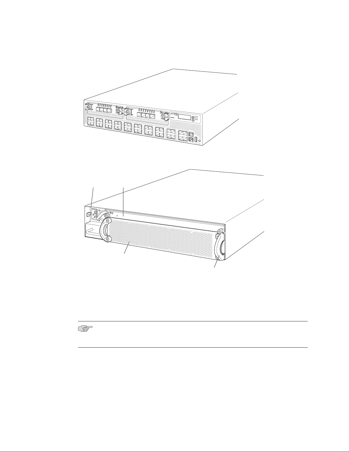
The EX4500 switch is 2 rack units (2 U) in size. Each EX4500 switch is designed to
optimize rack space utilization and cabling. See Figure 1 on page 4 and Figure 2
on page 4.
EX4500 Switches Hardware Overview ■ 3
Page 28
g020845
0
1
2
3
ST
0
1
2
3
ST
g020846
EX4500-LB
ST
0
1
Fan tray
AC power
supply
Intraconnect
module
Fan tray handle
Complete Hardware Guide for EX4500 Ethernet Switches
Figure 1: EX4500 Switch Front
Figure 2: EX4500 Switch Rear
EX4500 switches are available in two models—one with front-to-back airflow and
the other with back-to-front airflow. Both models provide 40 wire-speed 10-gigabit
small form-factor pluggable (SFP+) network ports that can house either 1-Gigabit
Ethernet connectors or 10-Gigabit Ethernet connectors. Both models support two
optional high-speed uplink modules.
NOTE: The side of the switch where the network ports are located is the front of the
switch.
4 ■ EX4500 Switches Hardware Overview
To provide carrier-class reliability, EX4500 switches include:
■ Dual redundant, load-sharing power supplies that are field-replaceable,
■ A field-replaceable fan tray with five fans. The switch remains operational if a
■ JUNOS Software with its modular design that enables failed system processes to
hot-removable, and hot-insertable.
single fan fails.
gracefully restart.
Page 29

Uplink Modules
Optional uplink modules are available for EX4500 switches. Two uplink modules can
be installed in an EX4500 switch. Each uplink module provides four SFP+ ports for
connecting to core devices in a data center. You can install SFP or SFP+ transceivers
in these ports.
Related Topics EX4500 Switch Models on page 5■
■ Field-Replaceable Units in EX4500 Switches on page 14
EX4500 Switch Models
The EX4500 switch is available in two models—one with front-to-back airflow and
the other with back-to-front airflow. Table 1 on page 5 lists the two models for an
EX4500 switch and the components included in each model.
Chapter 1: EX4500 Switch Overview
NOTE: The side of the switch where the network ports are located is the front of the
switch.
Table 1: EX4500 Switch Models and Their Components
Access Port
ConfigurationModel
EX4500-40F-FB
SFP/SFP+
EX4500-40F-BF
SFP/SFP+
Front-to-back40-port GbE/10GbE
Back-to-front40-port GbE/10GbE
Switch ComponentsDirection of Airflow
Chassis
■
One fan tray (with green exhaust label visible)
■
One AC power supply (with green ejector lever)
■
One power cord
■
One power supply cover panel
■
Two uplink module cover panels
■
One intraconnect module
■
Chassis
■
One fan tray (with orange intake label visible)
■
One AC power supply (with orange ejector
■
lever)
One power cord
■
One power supply cover panel
■
Two uplink module cover panels
■
One intraconnect module
■
EX4500 Switch Models ■ 5
Page 30

Complete Hardware Guide for EX4500 Ethernet Switches
NOTE: Uplink modules and transceivers are not part of the EX4500 switch’s shipping
configuration. If you want to purchase uplink modules, transceivers, or additional
power supplies for your switch configuration, you must order them separately.
CAUTION: Mixing power supplies with front-to-back airflow and back-to-front airflow
in the same chassis is not supported.
Related Topics ■ Chassis Physical Specifications for EX4500 Switches on page 6
■ Front Panel of an EX4500 Switch on page 7
■ Rear Panel of an EX4500 Switch on page 8
■ EX4500 Switches Hardware Overview on page 3
Chassis Physical Specifications for EX4500 Switches
The EX4500 switch chassis is a rigid sheet-metal structure that houses the other
switch components. Table 2 on page 6 summarizes the physical specifications of
the EX4500 switch chassis.
Table 2: Physical Specifications of the EX4500 Switch Chassis
ValueDescription
3.5 in. (8.9 cm)Chassis height
Chassis width
Weight
You can mount an EX4500 switch on a standard 19-in. two-post rack. You can also
mount an EX4500 switch on a standard 19-in. four-post rack or in a standard 19-in.
enclosed cabinet.
17.25 in. (43.82 cm)
■
The outer edges of the front-mounting brackets extend the width to 19 in. (48.3
■
cm).
21.1 in. (53.6 cm)Chassis depth
■
EX4500 switch with 1 AC power supply: 37 lb (17 kg)
■
AC power supply: 3 lb (1.3 kg)
■
Related Topics ■ Rack Requirements for EX4500 Switches on page 49
■ Cabinet Requirements for EX4500 Switches on page 50
■ Mounting an EX4500 Switch on page 65
6 ■ Chassis Physical Specifications for EX4500 Switches
Page 31

■ Installing and Connecting an EX4500 Switch on page 63
g020800
0 2
1 3
0 1 2 3
ST ST
0 1 2 3
4 6
5 7
8 10
9 11
12 14
13 15
16 18
17 19
20 22
21 23
24 26
25 27
28 30
29 31
32 34
33 35
36 38
CON
MGMT
37 39
Network ports Management port
Enter
button
Console
port
USB
port
ESD
point
LCD
panel
Chassis
status LEDs
Menu
button
0 2
1 3
Upper port numbers
Lower port numbers
0, 2, 4, 6.... 38
1, 3, 5, 7.... 39
■ Installing and Removing EX4500 Switch Hardware Components on page 73
Front Panel of an EX4500 Switch
The front panel of an EX4500 switch consists of the following components:
■ 40 SFP+ network ports
■ Network port LEDs
■ Two slots for installing uplink modules—Installing the uplink modules is optional.
■ LCD panel and the LCD navigation buttons
■ Chassis status LEDs
■ Console port
Chapter 1: EX4500 Switch Overview
■ Management port
■ Management port LEDs
■ USB port
■ ESD point
Figure 3 on page 7 shows the front panel of an EX4500 switch.
Figure 3: EX4500 Switch Front Panel
Related Topics ■ Rear Panel of an EX4500 Switch on page 8
■ LCD Panel in EX4500 Switches on page 9
■ Chassis Status LEDs in EX4500 Switches on page 13
Front Panel of an EX4500 Switch ■ 7
Page 32

g020801
EX4500-LB
ST
1
0
Fan
tray
AC power
supply LEDs
Fan tray handles
AC appliance
inlets
AC power
supplies
Intraconnect
module
Complete Hardware Guide for EX4500 Ethernet Switches
■ Network Port and Uplink Module Port LEDs in EX4500 Switches on page 15
■ Uplink Modules in EX4500 Switches on page 23
■ Optical Interface Support in EX4500 Switches on page 31
■ Installing and Removing EX4500 Switch Hardware Components on page 73
Rear Panel of an EX4500 Switch
The rear panel of the EX4500 switch consists of the following components:
■ Power supply or power supplies
■ AC appliance inlet
■ AC power supply LED
■ Fan tray
■ Intraconnect module
NOTE: The protective earthing terminal is located on the left side of the chassis. See
“Connecting Earth Ground to an EX Series Switch” on page 83.
Figure 4 on page 8 shows the rear panel of an EX4500 switch.
Figure 4: EX4500 Switch Rear Panel
Related Topics ■ Front Panel of an EX4500 Switch on page 7
■ Cooling System and Airflow in an EX4500 Switch on page 20
■ AC Power Supply in EX4500 Switches on page 18
■ Intraconnect Module in EX4500 Switches on page 25
■ Installing and Removing EX4500 Switch Hardware Components on page 73
8 ■ Rear Panel of an EX4500 Switch
Page 33

Chapter 2
Component Descriptions
■ LCD Panel in EX4500 Switches on page 9
■ Chassis Status LEDs in EX4500 Switches on page 13
■ Field-Replaceable Units in EX4500 Switches on page 14
■ Network Port and Uplink Module Port LEDs in EX4500 Switches on page 15
■ Management Port LEDs in EX4500 Switches on page 17
■ AC Power Supply in EX4500 Switches on page 18
■ AC Power Supply LEDs in EX4500 Switches on page 19
■ Cooling System and Airflow in an EX4500 Switch on page 20
■ Uplink Modules in EX4500 Switches on page 23
■ Intraconnect Module in EX4500 Switches on page 25
LCD Panel in EX4500 Switches
The LCD panel on the front panel of EX4500 switch shows two lines of text, each
that can contain a maximum of 16 characters. The LCD panel displays a variety of
information about the switch and also provides a menu to perform basic operations
such as initial setup and reboot.
There are two navigation buttons—Menu and Enter—to the right of the LCD panel.
See Figure 5 on page 9.
Figure 5: LCD Panel in EX4500 Switches
The first line of the text on the LCD panel displays the slot number, the role of the
switch, and the hostname. For EX4500 switches, the slot number is always 00 and
the role is always RE.
LCD Panel in EX4500 Switches ■ 9
Page 34

Complete Hardware Guide for EX4500 Ethernet Switches
You can configure the second line of the LCD panel to display a custom message. If
the LCD panel is configured to display a custom message, the Menu button and the
Enter button are disabled. See Configuring the LCD Panel on EX Series Switches (CLI
Procedure).
The LCD panel has a backlight. If the LCD panel remains idle for 60 seconds, the
backlight turns off. You can turn on the backlight by pressing the Menu or Enter
button once. After turning on the backlight, you can toggle between the LCD panel
menus by pressing the Menu button and navigate through the menu options by
pressing the Enter button.
NOTE: The chassis viewer in the J-Web interface also displays the LCD panel. From
the J-Web interface, you can view real-time status information in the LCD panel. See
Dashboard for EX Series Switches.
This topic describes:
LCD Panel Modes
■ LCD Panel Modes on page 10
■ LCD Panel Menus on page 11
The LCD panel operates in four modes: boot, idle, status, and maintenance.
The LCD panel operates in boot mode during switch reboot. The boot mode displays
the key milestones in the switch boot process. The boot mode does not have any
menu options. After the boot process is complete, the LCD panel automatically reverts
to the Idle menu.
In the idle mode, the second line of text on the LCD panel displays the mode of the
network ports’ Status LED and the number of chassis alarms. The number of alarms
is updated every second.
In the status mode, the second line displays:
■ Status of the power supplies
■ Status of the fans in the fan tray and the chassis temperature
■ Version of JUNOS Software for EX Series switches loaded on the switch
In the maintenance mode, the second line displays one of the following options that
you can use to configure and troubleshoot the switch:
■ System halt
■ System reboot
■ Load rescue
■ Factory default
■ EZSetup
10 ■ LCD Panel in EX4500 Switches
Page 35

LCD Panel Menus
The LCD panel has three menus: Idle, Status, and Maintenance. You can toggle
between the LCD panel menus by pressing the Menu button and navigate through
the menu options by pressing the Enter button.
Table 3 on page 11 describes the LCD panel menu options.
Table 3: LCD Panel Menu Options in EX4500 Switches
DescriptionMenu
Chapter 2: Component Descriptions
IDLE
STATUS
In the Idle menu:
■
Press Enter to cycle through the Status LED modes, which are port status
indicators:
ADM (administrative status)
■
DPX (duplex)
■
SPD (speed)
■
See “Network Port and Uplink Module Port LEDs in EX4500 Switches” on
page 15 for information on the Status LED modes.
■
Press Menu to exit the Idle menu and go to the Status menu.
The Status menu has the following options:
Show PSU Status—Choose one of the following:
■
■
Press Enter to display the status of power supplies: OK, Fld (Failed),
ABS (Absent).
■
Press Menu to go to the next option in the Status menu.
Show Environment Status—Choose one of the following:
■
■
Press Enter to display the status of the fan tray and the chassis
temperature:
Fan tray status: OK, Fld, ABS
■
Chassis temperature status: OK, High, Shutdown
■
■
Press Menu to go to the next option in the Status menu.
Show JUNOS Version Status—Choose one of the following: .
■
■
Press Enter to display the version of JUNOS Software for EX Series
switches loaded on the switch.
■
Press Menu to go to the next option in the Status menu.
EXIT STAT MENU?—Choose one of the following:
■
■
Press Enter to exit the Status menu.
■
Press Menu to return to the Show PSU Status option.
You can disable the Status menu or the options in the Status menu in the LCD
panel. See Configuring the LCD Panel on EX Series Switches (CLI Procedure).
LCD Panel in EX4500 Switches ■ 11
Page 36

Complete Hardware Guide for EX4500 Ethernet Switches
Table 3: LCD Panel Menu Options in EX4500 Switches (continued)
DescriptionMenu
MAINT (Maintenance Menu)
The Maintenance menu has the following options to configure and troubleshoot
the switch:
SYSTEM HALT?—Choose one of the following:
■
■
Press Enter to halt the switch. Press Enter again to confirm the halt.
■
Press Menu to go to the next option in the Maintenance menu.
SYSTEM REBOOT?—Choose one of the following:
■
■
Press Enter to reboot the switch. Press Enter again to confirm the reboot.
■
Press Menu to go to the next option in the Maintenance menu.
LOAD RESCUE?—Choose one of the following:
■
■
Press Enter to roll back the switch to the previous valid configuration.
Press Enter again to confirm the rollback.
■
Press Menu to go to the next option in the Maintenance menu.
FACTORY DEFAULT?—Choose one of the following:
■
■
Press Enter to restore the switch to the factory default configuration.
Press Enter again to confirm the restoration. The LCD flashes a success
or failure message and returns to the Idle menu.
■
Press Menu to go to the next option in the Maintenance menu.
ENTER EZSETUP?—Choose one of the following:
■
■
Press Enter to launch EZSetup. Press Enter again to confirm the launch.
EZSetup configures DHCP and enables the J-Web user interface on the
switch. The LCD flashes a success or failure message for approximately
10 seconds and returns to the Idle menu.
■
Press Menu to go to the next option in the Maintenance menu.
For information about EZSetup, see “Connecting and Configuring an EX
Series Switch (J-Web Procedure)” on page 109.
Related Topics ■ Front Panel of an EX4500 Switch on page 7
■ Field-Replaceable Units in EX4500 Switches on page 14
■ Connecting and Configuring an EX Series Switch (CLI Procedure) on page 107
■ Connecting and Configuring an EX Series Switch (J-Web Procedure) on page 109
12 ■ LCD Panel in EX4500 Switches
NOTE: You can use EZSetup only if the switch is in the factory default
configuration.
EXIT MAINT MENU?—Choose one of the following:
■
■
Press Enter to exit the Maintenance menu.
■
Press Menu to return to the SYSTEM HALT option.
You can disable the Maintenance menu or the options in the Maintenance menu
in the LCD panel. See Configuring the LCD Panel on EX Series Switches (CLI
Procedure).
Page 37

Chassis Status LEDs in EX4500 Switches
The front panel of an EX4500 switch has three chassis status LEDs (labeled ALM,
SYS, and MST) on the far right side of the panel, next to the Menu and Enter buttons
(see Figure 6 on page 13).
Figure 6: Chassis Status LEDs in an EX4500 Switch
Table 4 on page 13 describes the chassis status LEDs in an EX4500 switch, their
colors and states, and the status they indicate. You can view the colors of the three
LEDs remotely through the CLI by issuing the operational mode command show
chassis led.
Chapter 2: Component Descriptions
Table 4: Chassis Status LEDs in an EX4500 Switch
GreenSYS (System)
GreenMST (Master)
A major alarm (red) indicates a critical error condition that requires immediate action.
A minor alarm (amber) indicates a noncritical condition that requires monitoring or
maintenance. A minor alarm that is left unchecked might cause interruption in service
or performance degradation.
All three LEDs can be lit simultaneously.
State and DescriptionColorLED Label
There is no alarm.UnlitALM (Alarm)
There is a major alarm.Red
There is a minor alarm.Amber
On steadily—JUNOS Software for EX Series switches has
■
been loaded on the switch.
Blinking—The switch is booting.
■
Off—The switch is powered off.
■
On steadily—The switch is functioning normally.
■
Off—The switch is powered off.
■
Related Topics Front Panel of an EX4500 Switch on page 7■
■ Checking Active Alarms with the J-Web Interface
Chassis Status LEDs in EX4500 Switches ■ 13
Page 38

Complete Hardware Guide for EX4500 Ethernet Switches
■ Understanding Alarm Types and Severity Levels on EX Series Switches
Field-Replaceable Units in EX4500 Switches
Field-replaceable units (FRUs) are components that you can replace at your site. The
field-replaceable units (FRUs) in EX4500 switches are:
■ Power supplies
■ Fan tray
■ Uplink module(s)
■ SFP+ transceivers
■ SFP transceivers
■ Intraconnect module
NOTE: Uplink modules and transceivers are not part of the standard package and
must be ordered separately.
The power supplies, fan tray, uplink module(s), and transceivers are hot-removable
and hot-insertable: You can remove and replace them without powering off the switch
or disrupting switch functions.
NOTE: If you have a Juniper J-Care service contract, register any addition, change,
or upgrade of hardware components at
https://www.juniper.net/customers/csc/management/updateinstallbase.jsp. Failure to do so
can result in significant delays if you need replacement parts. This note applies if
you change the type of power supply or add a new type of uplink module. It does
not apply if you replace these components with the same type of component.
Related Topics ■ Installing a Power Supply in an EX4500 Switch on page 74
■ Removing a Power Supply from an EX4500 Switch on page 118
■ Installing a Fan Tray in an EX4500 Switch on page 75
■ Removing a Fan Tray from an EX4500 Switch on page 119
■ Installing an Uplink Module in an EX4500 Switch on page 77
■ Removing an Uplink Module from an EX4500 Switch on page 121
■ Installing a Transceiver in an EX Series Switch on page 81
■ Removing a Transceiver from an EX Series Switch on page 126
■ Installing an Intraconnect Module in an EX4500 Switch on page 79
■ Removing an Intraconnect Module from an EX4500 Switch on page 123
14 ■ Field-Replaceable Units in EX4500 Switches
Page 39

g020802
0 2
1 3
0 21 3 ST 0 21 3 ST
4 6
5 7
8 10
9 11
12 14
13 15
16 18
17 19
20 22
21 23
24 26
25 27
28 30
29 31
32 34
33 35
36 38
CON
MGMT
37 39
Status
lower port
Status
upper port
Link/Activity
lower port
Link/Activity
upper port
g020803
0
1
2
3
ST
Link/Activity
LED
Status
LED
0
1
2
3
Chapter 2: Component Descriptions
Network Port and Uplink Module Port LEDs in EX4500 Switches
Each network port and uplink module port on an EX4500 switch has two LEDs that
indicate link/activity and status. The figures in this topic show the location of these
LEDs:
■ Figure 7 on page 15 shows the location of the LEDs on the network ports on the
front panel of an EX4500 switch. The LEDs point toward the port to which the
LEDs belong.
■ Figure 8 on page 15 shows the location of the LEDs on the uplink module ports
on the SFP+ uplink module.
Figure 7: Network Port LEDs
Figure 8: Uplink Module Port LEDs
The LEDs labeled Link/Activity LED in Figure 7 on page 15 and Figure 8 on page 15
indicate link activity.
Table 5 on page 16 describes the Link/Activity LED.
Network Port and Uplink Module Port LEDs in EX4500 Switches ■ 15
Page 40

Complete Hardware Guide for EX4500 Ethernet Switches
Table 5: Link/Activity LED on Network Ports and Uplink Module Ports in EX4500 Switches
State and DescriptionColorLED
GreenLink/Activity
Blinking—The port and the link are active, and there is
■
link activity.
On steadily—The port and the link are active, but there
■
is no link activity.
Off—The port is not active.
■
The Status LED in Figure 7 on page 15 and Figure 8 on page 15 indicate the status
of one of the three port parameters. The port parameters are administrative status,
duplex mode, and speed.
Table 6 on page 16 describes the Status LED on network ports and uplink module
ports in EX4500 switches. From the Idle menu of the LCD, use the Enter button on
the LCD panel to toggle between the ADM, DPX, and SPD indicators.
Table 6: Status LED on Network Ports and Uplink Module Ports in EX4500 Switches
State and DescriptionLCD IndicatorLED
LED: ADMStatus
Indicates the administrative status (enabled or disabled).
The status indicators are:
Green—Port is administratively enabled.
■
Unlit—Port is administratively disabled.
■
Related Topics Front Panel of an EX4500 Switch on page 7■
LED: DPX
Indicates the duplex mode.
The status indicators for network ports on the front panel are:
Green—Port is set to full-duplex mode.
■
Unlit—Port is set to half-duplex mode.
■
The uplink module ports are always set to full-duplex mode;
therefore, the LED is always green.
LED: SPD
Indicates the speed.
The speed indicators are:
Blinking green—1 Gbps
■
Steadily green—10 Gbps
■
■ Uplink Modules in EX4500 Switches on page 23
16 ■ Network Port and Uplink Module Port LEDs in EX4500 Switches
Page 41

Management Port LEDs in EX4500 Switches
g020805
34
35
36 38
CON
MGMT
37 39
Management
port
Link/Activity
LED
Status
LED
MGMT
The management port on the front panel of an EX4500 switch has two LEDs that
indicate link/activity and port status (see Figure 9 on page 17).
Figure 9: LEDs on the Management Port on an EX4500 Switch
Chapter 2: Component Descriptions
Table 7 on page 17 describes the Link/Activity LED.
Table 7: Link/Activity LED on the Management Port on an EX4500 Switch
State and DescriptionColorLED
GreenLink/Activity
Blinking—The port and the link are active, and there is
■
link activity.
On steadily—The port and the link are active, but there
■
is no link activity.
Off—The port is not active.
■
Table 8 on page 17 describes the Status LED.
Table 8: Status LED on the Management Port on an EX4500 Switch
State and DescriptionColorLED
GreenStatus
Indicates the speed. The speed indicators are:
One blink per second—10 Mbps
■
Two blinks per second—100 Mbps
■
Three blinks per second—1000 Mbps
■
Related Topics Front Panel of an EX4500 Switch on page 7■
■ Connecting an EX Series Switch to a Network for Out-of-Band Management on
page 91
Management Port LEDs in EX4500 Switches ■ 17
Page 42

g020808
Ejector
lever
Power supply
LED
Power supply
handle
AC appliance
inlet
Complete Hardware Guide for EX4500 Ethernet Switches
AC Power Supply in EX4500 Switches
The AC power supply in EX4500 switches is a hot-insertable and hot-removable
field-replaceable unit (FRU).
EX4500 switches are shipped with one power supply. A cover panel is installed in
the second power supply slot. You can add a second power supply to the switch.
Power supplies are installed at the rear of the chassis in slots labeled 1 and 0. Both
power supplies are accessible from the rear of the chassis.
WARNING: The switch is pluggable type A equipment installed in a restricted-access
location. It has a separate protective earthing terminal provided on the chassis in
addition to the grounding pin of the power supply cord. This separate protective
earthing terminal must be permanently connected to earth ground. See “Connecting
Earth Ground to an EX Series Switch” on page 83
Each AC power supply weighs approximately 3 lb (1.3 kg) and has an independent
12 A rated AC appliance inlet on its front. Each inlet requires a dedicated AC power
feed. Each AC power supply has a fan, a bicolor LED on the faceplate that indicates
the status of the power supply, and a colored ejector lever. See Figure 10 on page 18.
Figure 10: AC Power Supply
Each AC power supply has an ejector lever that holds the power supply in place. The
ejector lever locks into the corresponding hole in the chassis on the left side of the
AC appliance inlet. For instructions for installing the power supply, see “Installing a
Power Supply in an EX4500 Switch” on page 74.
18 ■ AC Power Supply in EX4500 Switches
Each AC power supply comes with a power cord retainer that holds the power cord
in place. See Figure 11 on page 19. The power cord retainer has a clip and an
adjustment nut. The L-shaped ends of the retainer clip hook into the bracket holes
on each side of the AC appliance inlet. The adjustment nut holds the power cord in
the correct position. For instructions for installing the power cord retainer, see
“Installing a Power Supply in an EX4500 Switch” on page 74.
Page 43

g020852
Retainer
clip
Adjustment
nut
Chapter 2: Component Descriptions
Figure 11: Power Cord Retainer for an AC Power Supply
Each power supply has its own fan and is cooled by its own internal cooling system.
The airflow for a power supply is either from the front of the power supply to the
back or from the back of the power supply to the front depending on the switch
model you purchase.
The color of the ejector lever on the power supply indicates the direction of airflow
of the power supply.
Related Topics Installing a Power Supply in an EX4500 Switch on page 74■
■ Green—Front-to-back airflow
■ Orange—Back-to-front airflow
The color of the power supply's ejector lever must match the color of the intake or
exhaust label visible through the vents of the installed fan tray. The color match
indicates that the direction of airflow through the fan tray matches the direction of
airflow through the power supply.
CAUTION: Verify that the direction of airflow through the power supply matches the
direction of airflow through the fan tray to prevent overheating of the chassis.
Each AC power supply provides power to all components in the switch. The two
power supplies provide full power redundancy to the switch. If one power supply
fails or is removed, the second power supply balances the electrical load without
interruption. The switch reassesses the power required to support the switch
configuration and issues error messages if the available power is insufficient.
The output for the AC power supply is 12 VDC. The output power is 1000 W.
■ AC Power Specifications for EX4500 Switches on page 57
■ AC Power Supply LEDs in EX4500 Switches on page 19
AC Power Supply LEDs in EX4500 Switches
An AC power supply has one bicolor LED on its faceplate. This LED displays
information about the status of the power supply. See Figure 12 on page 20.
AC Power Supply LEDs in EX4500 Switches ■ 19
Page 44

g020809
AC power
supply LEDs
Complete Hardware Guide for EX4500 Ethernet Switches
Figure 12: AC Power Supply LEDs in EX4500 Switches
Table 9 on page 20 describes the LED on an AC power supply in an EX4500 switch.
Table 9: Power Supply LED on EX4500 Switches
DescriptionLED State
Unlit
Green
Amber
Indicates one of the following:
Power supply is disconnected from AC power feed.
■
AC power input voltage is not within normal operating range.
■
No AC power input.
■
On steadily—Power supply is functioning normally.
■
Blinking—Power supply has failed.
■
On steadily—Power supply has failed.
■
Blinking—Power supply has failed.
■
Related Topics AC Power Specifications for EX4500 Switches on page 57■
■ AC Power Cord Specifications for an EX4500 Switch on page 57
■ Connecting AC Power to an EX4500 Switch on page 89
Cooling System and Airflow in an EX4500 Switch
20 ■ Cooling System and Airflow in an EX4500 Switch
The cooling system in an EX4500 switch consists of a single fan tray. The fan tray
is a hot-insertable and hot-removable field-replaceable unit (FRU). The fan tray
contains five fans (see Figure 13 on page 21).
Page 45

g020812
Fan tray handles
Front
Rear
Fans (5)
g020813
Chapter 2: Component Descriptions
Figure 13: Fan Tray Used in an EX4500 Switch
The fan tray installs horizontally in the rear of the chassis. The fan tray has two
handles, one on each side that facilitate handling of the fan tray.
You remove and replace the fan tray from the rear of the chassis. The switch continues
to operate for a limited time (15 seconds) during the replacement of the fan tray
without thermal shutdown.
The fan tray provides front-to-back or back-to-front airflow depending on the switch
model you purchase.
In the EX4500-40F-FB model, the air intake to cool the chassis is located on the front
of the chassis. Air is pulled into the chassis and pushed toward the fan tray. Hot air
exhausts from the rear of the chassis. See Figure 14 on page 21.
Figure 14: Front-to-Back Airflow Through the EX4500-40F-FB Switch Chassis
In the EX4500-40F-BF model, the air intake to cool the chassis is located on the rear
of the chassis. Air is pulled into the chassis and pushed away from the fan tray. Hot
air exhausts from the front of the chassis. See Figure 15 on page 22.
Cooling System and Airflow in an EX4500 Switch ■ 21
Page 46

Front
Rear
Fans (5)
g020816
Complete Hardware Guide for EX4500 Ethernet Switches
Figure 15: Back-to-Front Airflow Through the EX4500-40F-BF Switch Chassis
Each fan tray has colored intake or exhaust labels that are visible through the fan
tray vents. The intake label is orange. The exhaust label is green.
NOTE: Only one of the labels, intake or exhaust, is visible through the vents of the
installed fan tray.
The color of the label visible through the vents of the installed fan tray must match
the color of the ejector lever on the installed power supply. The color match indicates
that the power supply has the correct airflow for this model. See “AC Power Supply
in EX4500 Switches” on page 18.
CAUTION: To prevent overheating of the chassis, verify that the color of the label
visible through the vents of the installed fan tray matches the color of the ejector
lever of the installed power supply. A color match indicates that the direction of
airflow through the fan tray matches the direction of airflow of the power supply.
Temperature sensors in the chassis monitor the temperature within the chassis. The
fan tray used in the switch comes with load-sharing redundancy that can tolerate a
single fan failure at room temperature (below 113° F/45° C) to still provide sufficient
cooling.
Under normal operating conditions, the fans in the fan tray run at less than full speed.
If a fan fails or the ambient temperature rises above the threshold 113°F (45°C), the
speed of the remaining fans is automatically adjusted to keep the temperature within
the acceptable range, 32°F (0°C) through 113°F (45°C).
The system raises an alarm if the fan fails or if the ambient temperature inside the
chassis rises above the acceptable range. If the temperature inside the chassis rises
above the threshold temperature, the system shuts down automatically.
22 ■ Cooling System and Airflow in an EX4500 Switch
Page 47

You can check the status of fans and the chassis temperature from the Environment
g020856
0 2
1 3
0 1 2 3
ST ST
0 1 2 3
4 6
5 7
8 10
9 11
12 14
13 15
16 18
17 19
20 22
21 23
24 26
25 27
28 30
29 31
32 34
33 35
36 38
CON
MGMT
37 39
Uplink Module
(PIC 1)
Uplink Module
(PIC 2)
Status option in the Status menu on the LCD panel. See “LCD Panel in EX4500
Switches” on page 9.
You cannot replace a single fan. If one or more fans fail, you must replace the entire
fan tray.
Related Topics ■ Installing a Fan Tray in an EX4500 Switch on page 75
■ Removing a Fan Tray from an EX4500 Switch on page 119
■ Field-Replaceable Units in EX4500 Switches on page 14
■ Rear Panel of an EX4500 Switch on page 8
■ Prevention of Electrostatic Discharge Damage on EX Series Switches on page 174
Uplink Modules in EX4500 Switches
Chapter 2: Component Descriptions
EX4500 switches support SFP+ uplink modules. The SFP+ uplink module is a
hot-insertable and hot-removable field replaceable unit (FRU).
NOTE: Uplink modules and transceivers are not part of the EX4500 switch’s shipping
configuration. You must order them separately.
You can install up to two SFP+ uplink modules in an EX4500 switch. Both uplink
modules install horizontally on the front of the chassis. The uplink module slot on
the left is PIC 1. The uplink module slot on the right is PIC 2. See Figure 16 on
page 23.
Figure 16: Uplink Module Slots in an EX4500 Switch
Each SFP+ uplink module provides four ports. Each module can house four 10-gigabit
small form-factor pluggable (SFP+) transceivers or four 1-gigabit small form-factor
pluggable (SFP) transceivers.
Uplink Modules in EX4500 Switches ■ 23
Page 48

g020806
0
1
2
3
ST
Link/Activity
LED
Status
LED
Status LED
Complete Hardware Guide for EX4500 Ethernet Switches
NOTE: When a new uplink module is installed in the switch or an existing uplink
module is replaced with another uplink module, the switch detects the newly installed
uplink module. The switch creates the required interfaces when new transceivers
are installed in those ports.
The operating mode for an SFP+ uplink module is shown in the output of the show
chassis pic fpc-slot slot number pic-slot 1 command.
You can use the uplink module ports to connect an access switch to a distribution
switch.
Figure 17 on page 24 shows the SFP+ uplink module.
Figure 17: SFP+ Uplink Module
The SFP+ uplink module has an LED on the faceplate (labeled ST) that indicates the
status of the uplink module. See Figure 17 on page 24.
Table 10 on page 24 describes the LED on the uplink module in an EX4500 switch.
Table 10: Uplink Module Status LED
UnlitST
Each uplink module port has a pair of LEDs that indicate the link/activity and status
of the port. See “Network Port and Uplink Module Port LEDs in EX4500 Switches”
on page 15 for details about the uplink module port LEDs.
The SFP+ uplink modules are shipped with dust covers preinstalled in the ports.
The SFP+ uplink modules require JUNOS Software for EX Series switches, Release
9.4 or later.
DescriptionStateLED
The uplink module is offline.
■
The chassis is powered off.
■
The uplink module is online and functioning normally.Green
■
24 ■ Uplink Modules in EX4500 Switches
Page 49

Related Topics ■ Network Port and Uplink Module Port LEDs in EX4500 Switches on page 15
g020853
ST
Status LED
Captive screws
■ Network Port and Uplink Module Port Connector Pinout Information for EX4500
Switches on page 30
■ Optical Interface Support in EX4500 Switches on page 31
■ SFP+ Direct Attach Cables for EX4500 and EX8200 Switches on page 36
■ EX Series Switches Interfaces Overview
■ Installing an Uplink Module in an EX4500 Switch on page 77
■ Removing an Uplink Module from an EX4500 Switch on page 121
Intraconnect Module in EX4500 Switches
The intraconnect module is installed horizontally on the rear of an EX4500 switch
chassis. The intraconnect module helps the switch achieve line rate on all its ports.
The module comes preinstalled in the switch chassis. It is a field-replaceable unit.
Chapter 2: Component Descriptions
CAUTION: Operating an EX4500 switch without the intraconnect module is not
supported.
Figure 18 on page 25 shows the intraconnect module.
Figure 18: Intraconnect Module
The intraconnect module has an LED (labeled ST) on the faceplate that indicates the
status of the intraconnect module.
Table 11 on page 25 describes the LED on the intraconnect module in an EX4500
switch.
Table 11: Intraconnect Module Status LED
GreenST
DescriptionStateLED
The intraconnect module is functioning
normally.
Unlit
The intraconnect module is not
■
functioning normally.
The switch has been powered off.
■
Intraconnect Module in EX4500 Switches ■ 25
Page 50

Complete Hardware Guide for EX4500 Ethernet Switches
The intraconnect module has two captive screws on the faceplate that secure the
module in the chassis. To remove or replace the intraconnect module, follow the
instructions in “Removing an Intraconnect Module from an EX4500 Switch” on
page 123.
Related Topics Rear Panel of an EX4500 Switch on page 8■
■ Field-Replaceable Units in EX4500 Switches on page 14
■ Installing an Intraconnect Module in an EX4500 Switch on page 79
26 ■ Intraconnect Module in EX4500 Switches
Page 51

Chapter 3
Component Specifications
■ USB Port Specifications for an EX Series Switch on page 27
■ Console Port Connector Pinout Information for an EX Series Switch on page 28
■ Management Port Connector Pinout Information for an EX4500
Switch on page 29
■ Network Port and Uplink Module Port Connector Pinout Information for EX4500
Switches on page 30
■ Optical Interface Support in EX4500 Switches on page 31
■ SFP+ Direct Attach Cables for EX4500 and EX8200 Switches on page 36
■ Grounding Cable and Lug Specifications for EX4500 Switches on page 39
USB Port Specifications for an EX Series Switch
The following Juniper Networks USB flash drives have been tested and are officially
supported for the USB port on all EX Series switches:
■ RE-USB-1G-S
■ RE-USB-2G-S
■ RE-USB-4G-S
CAUTION: Any USB memory product not listed as supported for EX Series switches
has not been tested by Juniper Networks. The use of any unsupported USB memory
product could expose your EX Series switch to unpredictable behavior. Juniper
Networks Technical Assistance Center (JTAC) can provide only limited support for
issues related to unsupported hardware. We strongly recommend that you use only
supported USB flash drives.
All USB flash drives used on EX Series switches must have the following features:
■ USB 2.0 or later.
■ Formatted with a FAT or MS-DOS file system.
■ If the switch is running JUNOS Release 9.5 or earlier, the formatting method
must use a master boot record. Windows formatting, by default, does not use a
master boot record. See the documentation for your USB flash drive for
information on how your USB flash drive is formatted.
USB Port Specifications for an EX Series Switch ■ 27
Page 52

Complete Hardware Guide for EX4500 Ethernet Switches
Related Topics ■ See Rear Panel of an EX2200 Switch for port location.
■ See Rear Panel of an EX3200 Switch for port location.
■ See Rear Panel of an EX4200 Switch for port location.
■ See Front Panel of an EX4500 Switch on page 7 for port location.
■ See Switch Fabric and Routing Engine (SRE) Module in an EX8208 Switch for
port location.
■ See Routing Engine (RE) Module in an EX8216 Switch for port location.
■ Booting an EX Series Switch Using a Software Package Stored on a USB Flash
Drive
Console Port Connector Pinout Information for an EX Series Switch
The console port on an EX Series switch is an RS-232 serial interface that uses an
RJ-45 connector to connect to a console management device. The default baud rate
for the console port is 9600 baud.
Table 12 on page 28 provides the pinout information for the RJ-45 console connector.
An RJ-45 cable and an RJ-45 to DB-9 serial port adapter are supplied with the switch.
NOTE: If your laptop or PC does not have a DB-9 male connector pin and you want
to connect your laptop or PC directly to an EX Series switch, use a combination of
the RJ-45 to DB-9 female adapter supplied with the switch and a USB to DB-9 male
adapter. You must provide the USB to DB-9 male adapter.
Table 12: EX Series Switches Console Port Connector Pinout Information
DescriptionSignalPin
Request to sendRTS Output1
Data terminal readyDTR Output2
Transmit dataTxD Output3
Signal groundSignal Ground4
Signal groundSignal Ground5
Receive dataRxD Input6
28 ■ Console Port Connector Pinout Information for an EX Series Switch
Data carrier detectCD Input7
Clear to sendCTS Input8
Page 53

Chapter 3: Component Specifications
Related Topics ■ See Rear Panel of an EX2200 Switch for port location.
■ See Rear Panel of an EX3200 Switch for port location.
■ See Rear Panel of an EX4200 Switch for port location.
■ See Front Panel of an EX4500 Switch on page 7 for port location.
■ See Switch Fabric and Routing Engine (SRE) Module in an EX8208 Switch for
port location.
■ See Routing Engine (RE) Module in an EX8216 Switch for port location.
■ Connecting an EX Series Switch to a Management Console on page 92
Management Port Connector Pinout Information for an EX4500 Switch
The management port on an EX4500 switch uses an RJ-45 connector to connect to
a management device for out-of-band management.
The port uses an autosensing RJ-45 connector to support a 10/100/1000Base-T
connection. Two LEDs on the port indicate link/activity on the port and the
administrative status of the port. See “Management Port LEDs in EX4500 Switches”
on page 17.
Table 13 on page 29 provides the pinout information for the RJ-45 connector for the
management port. An RJ-45 cable, with a connector attached, is supplied with the
switch.
Table 13: Management Port Connector Pinout Information for EX4500 Switches
DescriptionSignalPin
Transmit/receive data pair 1TRP1+1
Transmit/receive data pair 1TRP1-2
Transmit/receive data pair 2TRP2+3
Transmit/receive data pair 3TRP3+4
Transmit/receive data pair 3TRP3-5
Transmit/receive data pair 2TRP2-6
Transmit/receive data pair 4TRP4+7
Related Topics See Front Panel of an EX4500 Switch on page 7 for port location.■
Transmit/receive data pair 4TRP4-8
■ Connecting an EX Series Switch to a Network for Out-of-Band Management on
page 91
Management Port Connector Pinout Information for an EX4500 Switch ■ 29
Page 54

Complete Hardware Guide for EX4500 Ethernet Switches
Network Port and Uplink Module Port Connector Pinout Information for EX4500 Switches
The network ports and uplink module ports on an EX4500 switch have two LEDs on
each port that indicate link/activity on the port and the port status. See “Network
Port and Uplink Module Port LEDs in EX4500 Switches” on page 15.
Table 14 on page 30 provides the pinout information for the network port and uplink
module port connector pinout.
Table 14: Network Port and Uplink Module Port Connector Pinout Information for EX4500 Switches
DescriptionSignalPin
Module transmitter groundVeeT1
Module transmitter faultTX_Fault2
Transmitter disableTX_Disable3
2-wire serial interface data lineSDA4
2-wire serial interface clockSCL-5
Module absentMOD_ABS6
Rate select 0, optionally controls SFP+ module receiver.RS07
Receiver loss of signal indicationRX_LOS8
Rate select 1, optionally controls SFP+ transmitter.RS19
Module receiver groundVeeR10
Module receiver groundVeeR11
Receiver inverted data outputRD-12
Receiver non inverted data outputRD+13
Module receiver groundVeeR14
Module receiver 3.3 V supplyVccR15
Module transmitter 3.3 V supplyVccT16
Module transmitter groundVeeT17
Transmitter non inverted data inputTD+18
Transmitter inverted data inputTD-19
Module transmitter groundVeeT20
30 ■ Network Port and Uplink Module Port Connector Pinout Information for EX4500 Switches
Page 55

Related Topics Front Panel of an EX4500 Switch on page 7■
■ Uplink Modules in EX4500 Switches on page 23
Optical Interface Support in EX4500 Switches
Uplink module ports on EX4500 switches support SFP and SFP+ transceivers. This
topic describes the optical interfaces supported for those transceivers. It also lists
the copper interface supported for the SFP transceivers.
NOTE: Use only optical transceivers and optical connectors purchased from Juniper
Networks for your EX4500 switch.
The Gigabit Ethernet SFP and SFP+ transceivers installed in EX4500 switches support
digital optical monitoring (DOM): you can view the diagnostic details for these
transceivers by issuing the operational mode CLI command show interfaces diagnostics
optics. The command does not give any output for copper transceivers or transceivers
not purchased from Juniper Networks.
Chapter 3: Component Specifications
The two tables in this topic describe the optical interface support over single-mode
fiber-optic (SMF) and multimode fiber-optic (MMF) cables for SFP and SFP+
transceivers and over the copper interface for SFP transceivers:
■ Table 15 on page 32—Optical interface support and copper interface support
for Gigabit Ethernet SFP transceivers.
■ Table 16 on page 34—Optical interface support for Gigabit Ethernet SFP+
transceivers.
Optical Interface Support in EX4500 Switches ■ 31
Page 56

Complete Hardware Guide for EX4500 Ethernet Switches
Table 15: Optical Interface Support and Copper Interface Support for Gigabit Ethernet SFP Transceivers in
EX4500 Switches
SpecificationsEthernet Standard
EX-SFP-1GE-TModel Number1000Base-T
10/100/1000 MbpsRate
RJ-45Connector Type
CopperFiber Count
–Transmitter Wavelength
–Minimum Launch Power
–Maximum Launch Power
–Minimum Receiver Sensitivity
–Maximum Input Power
CopperFiber Type
–Core/Cladding Size
–Modal Bandwidth
100 m (328 ft)Distance
Not availableDOM Support
JUNOS Software for EX Series switches, Release 10.2 or laterSoftware required
32 ■ Optical Interface Support in EX4500 Switches
Page 57

Chapter 3: Component Specifications
Table 15: Optical Interface Support and Copper Interface Support for Gigabit Ethernet SFP Transceivers in
EX4500 Switches (continued)
SpecificationsEthernet Standard
EX-SFP-1GE-LXModel Number1000Base-LX
1000 MbpsRate
LCConnector Type
DualFiber Count
1310 nmTransmitter Wavelength
–9.5 dBmMinimum Launch Power
–3 dBmMaximum Launch Power
–25 dBmMinimum Receiver Sensitivity
–3 dBmMaximum Input Power
SMFFiber Type
9/125 µmCore/Cladding Size
–Modal Bandwidth
10 km (6.2 miles)Distance
AvailableDOM Support
JUNOS Software for EX Series switches, Release 10.2 or laterSoftware required
Optical Interface Support in EX4500 Switches ■ 33
Page 58

Complete Hardware Guide for EX4500 Ethernet Switches
Table 16: Optical Interface Support for Gigabit Ethernet SFP+ Transceivers in EX4500 Switches
SpecificationsEthernet Standard
EX-SFP-10GE-USRModel Number10GBase-SR
10 GbpsRate
LCConnector Type
DualFiber Count
850 nmTransmitter Wavelength
–7.3 dBmMinimum Launch Power
–1.3 dBmMaximum Launch Power
–11.1 dBmMinimum Receiver Sensitivity
Core/Cladding Size
Modal Bandwidth
Distance
–9.9 dBmMaximum Input Power
MMFFiber Type
62.5/125
µm
200
MHz/km
10 m
(32.8 ft)
AvailableDOM Support
JUNOS Software for EX Series switches, Release 10.2 or laterSoftware required
50/125
µm
500
MHz/km
30 m
(98.4 ft)
50/125
µm
OM3OM3OM1Fiber Grade
1500
MHz/km
100 m
(328 ft)
34 ■ Optical Interface Support in EX4500 Switches
Page 59

Chapter 3: Component Specifications
Table 16: Optical Interface Support for Gigabit Ethernet SFP+ Transceivers in EX4500 Switches (continued)
SpecificationsEthernet Standard
EX-SFP-10GE-SRModel Number10GBase-SR
10 GbpsRate
LCConnector Type
DualFiber Count
850 nmTransmitter Wavelength
–7.3 dBmMinimum Launch Power
–1 dBmMaximum Launch Power
–9.9 dBmMinimum Receiver Sensitivity
Core/Cladding Size
Modal Bandwidth
Distance
–1 dBmMaximum Input Power
MMFFiber Type
62.5/125
µm
160
MHz/km
26 m
(85 ft)
AvailableDOM Support
JUNOS Software for EX Series switches, Release 10.2 or laterSoftware required
62.5/125
µm
200
MHz/km
33 m
(108 ft)
50/125
µm
400
MHz/km
66 m
(216 ft)
50/125
µm
500
MHz/km
82 m
(269 ft)
50/125
µm
OM3OM2–OM1FDDIFiber Grade
1500
MHz/km
300 m
(984 ft)
Optical Interface Support in EX4500 Switches ■ 35
Page 60

Complete Hardware Guide for EX4500 Ethernet Switches
Table 16: Optical Interface Support for Gigabit Ethernet SFP+ Transceivers in EX4500 Switches (continued)
SpecificationsEthernet Standard
EX-SFP-10GE-LRModel Number10GBase-LR
10 GbpsRate
LCConnector Type
DualFiber Count
1310 nmTransmitter Wavelength
–8.2 dBmMinimum Launch Power
0.5 dBmMaximum Launch Power
–18 dBmMinimum Receiver Sensitivity
0.5 dBmMaximum Input Power
SMFFiber Type
9/125 µmCore/Cladding Size
–Modal Bandwidth
10 km (6.2 miles)Distance
AvailableDOM Support
JUNOS Software for EX Series switches, Release 10.2 or laterSoftware required
Related Topics Front Panel of an EX4500 Switch on page 7■
■ Installing a Transceiver in an EX Series Switch on page 81
■ Removing a Transceiver from an EX Series Switch on page 126
SFP+ Direct Attach Cables for EX4500 and EX8200 Switches
Small form-factor pluggable plus transceiver (SFP+) direct attach copper cables, also
known as Twinax cables, are suitable for in-rack connections between servers and
switches. They are suitable for short distances up to 7 m, making them ideal for
highly cost-effective networking connectivity within a rack and between adjacent
racks.
This topic describes:
■ Cable Specifications on page 37
■ Standards Supported by These Cables on page 38
36 ■ SFP+ Direct Attach Cables for EX4500 and EX8200 Switches
Page 61

Cable Specifications
Chapter 3: Component Specifications
Juniper Networks SFP+ direct attach cables are available in three lengths:
■ 1 m (3.3 ft)
■ 3 m (9.9 ft)
■ 7 m (23 ft)
NOTE: When you use SFP+ direct attach cables with your EX4500 and EX8200
switches, we recommend that you use only Juniper Networks SFP+ direct attach
cables.
The cables are hot-removable and hot-insertable. A cable comprises a low-voltage
cable assembly that connects directly into two SFP+ modules, one at each end of
the cable. The cables use high-performance integrated duplex serial data links for
bidirectional communication and are designed for data rates up to 10 Gbps.
Table 17 on page 37 describes the cable specifications.
Table 17: SFP+ Direct Attach Cable Specifications
SpecificationModel
10 Gbps full-duplex serial transmissionRateEX-SFP-10GE-DAC-1m
SFP+ passive Twinax cable assemblyConnector type
3.3 VSupply voltage
0.57 WPower consumption (per end)
-40°C to 85°CStorage temperature
TwinaxCable type
30 AWGWire AWG
1 in.Minimum cable bend radius
100 ohmCable characteristic impedance
2% maximumCrosstalk between pairs
1.31 nsec/ftTime delay
1 m (3.3 ft)Length
SFP+ Direct Attach Cables for EX4500 and EX8200 Switches ■ 37
Page 62

Complete Hardware Guide for EX4500 Ethernet Switches
Table 17: SFP+ Direct Attach Cable Specifications (continued)
SpecificationModel
10 Gbps full-duplex serial transmissionRateEX-SFP-10GE-DAC-3m
SFP+ passive Twinax cable assemblyConnector type
3.3 VSupply voltage
0.57 WPower consumption (per end)
-40°C to 85°CStorage temperature
TwinaxCable type
30 AWGWire AWG
1 in.Minimum cable bend radius
100 ohmCable characteristic impedance
2% maximumCrosstalk between pairs
1.31 nsec/ftTime delay
3 m (9.9 ft)Length
10 Gbps full-duplex serial transmissionRateEX-SFP-10GE-DAC-7m
SFP+ passive Twinax cable assemblyConnector type
3.3 VSupply voltage
0.57 WPower consumption (per end)
-40°C to 85°CStorage temperature
TwinaxCable type
24 AWGWire AWG
2 in.Minimum cable bend radius
100 ohmCable characteristic impedance
2% maximumCrosstalk between pairs
Standards Supported by These Cables
The cables comply with the following standards:
38 ■ SFP+ Direct Attach Cables for EX4500 and EX8200 Switches
1.31 nsec/ftTime delay
7 m (23 ft)Length
Page 63

Chapter 3: Component Specifications
■
SFP mechanical standard SFF-843—see ftp://ftp.seagate.com/sff/SFF-8431.PDF.
■
Electrical interface standard SFF-8432—see ftp://ftp.seagate.com/sff/SFF-8432.PDF.
■ SFP+ Multi-Source Alliance (MSA) standards
Related Topics ■ Optical Interface Support in EX8200 Switches
■ Optical Interface Support in EX4500 Switches on page 31
■ Installing a Transceiver in an EX Series Switch on page 81
■ Removing a Transceiver from an EX Series Switch on page 126
Grounding Cable and Lug Specifications for EX4500 Switches
For installations that require a separate grounding conductor to the chassis, the switch
must be adequately grounded before power is connected to ensure proper operation
and to meet safety and electromagnetic interference (EMI) requirements. To ground
an EX4500 switch, connect a grounding cable to earth ground and then attach it to
the chassis grounding points.
CAUTION: For installations that require a separate grounding conductor to the chassis,
use the protective earthing terminal on the switch chassis to connect to earth ground.
Before switch installation begins, a licensed electrician must attach a cable lug to the
grounding cables that you supply. See “Connecting Earth Ground to an EX Series
Switch” on page 83. A cable with an incorrectly attached lug can damage the switch.
A pair of threaded inserts (PEM nuts) is provided on the left side towards the rear
corner of the chassis for connecting the switch to earth ground. The grounding points
fit UNC 10-32 screws. The grounding points are spaced at 0.625 in. (15.86 mm).
The grounding cable that you provide for an EX4500 switch must be 14 AWG (2
mm2), minimum 90°C wire, or as permitted by the local code.
NOTE: Grounding is provided to an AC-powered switch when you plug its power
supplies into grounded AC power receptacles.
WARNING: The switch is pluggable type A equipment installed in a restricted-access
location. It has a separate protective earthing terminal provided on the chassis in
addition to the grounding pin of the power supply cord. This separate protective
earthing terminal must be permanently connected to earth ground for installations
that require a separate grounding conductor to the chassis.
Related Topics AC Power Supply in EX4500 Switches on page 18■
Grounding Cable and Lug Specifications for EX4500 Switches ■ 39
Page 64

Complete Hardware Guide for EX4500 Ethernet Switches
■ Installing a Power Supply in an EX4500 Switch on page 74
40 ■ Grounding Cable and Lug Specifications for EX4500 Switches
Page 65

Part 2
Planning for Switch Installation
■ Site Preparation on page 43
■ Rack and Cabinet Requirements on page 49
■ Cable Requirements on page 55
■ Planning Power Requirements on page 57
Planning for Switch Installation ■ 41
Page 66

Complete Hardware Guide for EX4500 Ethernet Switches
42 ■ Planning for Switch Installation
Page 67

Chapter 4
Site Preparation
■ Site Preparation Checklist for EX4500 Switches on page 43
■ General Site Guidelines for EX Series Switches on page 44
■ Site Electrical Wiring Guidelines for EX Series Switches on page 45
■ Environmental Requirements and Specifications for EX Series
Switches on page 46
Site Preparation Checklist for EX4500 Switches
The checklist in Table 18 on page 43 summarizes the tasks you need to perform
when preparing a site for EX4500 switch installation.
Table 18: Site Preparation Checklist
Environment
Verify that environmental factors such as
temperature and humidity do not exceed
switch tolerances.
“Environmental Requirements and
Specifications for EX Series
Switches” on page 46
DatePerformed ByFor More InformationItem or Task
Power
Measure distance between external power
sources and switch installation site.
Locate sites for connection of system
grounding.
Calculate the power consumption and
requirements.
Hardware Configuration
Choose the number and types of switches you
want to install.
Rack or Cabinet
“AC Power Specifications for
EX4500 Switches” on page 57
“EX4500 Switches Hardware
Overview” on page 3
Site Preparation Checklist for EX4500 Switches ■ 43
Page 68

Complete Hardware Guide for EX4500 Ethernet Switches
Table 18: Site Preparation Checklist (continued)
DatePerformed ByFor More InformationItem or Task
Verify that your rack or cabinet meets the
minimum requirements for the installation of
“Rack Requirements for EX4500
Switches” on page 49
the switch.
“Cabinet Requirements for EX4500
Switches” on page 50
Plan rack or cabinet location, including required
space clearances.
“Clearance Requirements for Airflow
and Hardware Maintenance for
EX4500 Switches” on page 52
Secure the rack or cabinet to the floor and
building structure.
Cables
Acquire cables and connectors:
Determine the number of cables needed
■
based on your planned configuration.
Review the maximum distance allowed
■
for each cable. Choose the length of cable
based on the distance between the
hardware components being connected.
Plan the cable routing and management.
Related Topics ■ General Safety Guidelines and Warnings for EX Series Switches on page 145
■ General Site Guidelines for EX Series Switches on page 44
■ Installing and Connecting an EX4500 Switch on page 63
■ Mounting an EX4500 Switch on page 65
General Site Guidelines for EX Series Switches
Efficient switch operation requires proper site planning and maintenance and proper
layout of the equipment, rack or cabinet (if used), and wiring closet.
To plan and create an acceptable operating environment for your EX Series switch
and prevent environmentally caused equipment failures:
■ Keep the area around the chassis free from dust and conductive material, such
as metal flakes.
■ Follow prescribed airflow guidelines to ensure that the cooling system functions
properly and that exhaust from other equipment does not blow into the intake
vents of the switch.
44 ■ General Site Guidelines for EX Series Switches
Page 69

Chapter 4: Site Preparation
■ Follow the prescribed ESD prevention procedures to avoid damaging the
equipment. Static discharge can cause components to fail completely or
intermittently over time.
■ Install the switch in a secure area, so that only authorized personnel can access
the switch.
Related Topics ■ Prevention of Electrostatic Discharge Damage on EX Series Switches on page 174
■ Clearance Requirements for Airflow and Hardware Maintenance for EX2200
Switches
■ Clearance Requirements for Airflow and Hardware Maintenance for EX3200 and
EX4200 Switches
■ Clearance Requirements for Airflow and Hardware Maintenance for EX4500
Switches on page 52
■ Clearance Requirements for Airflow and Hardware Maintenance for an EX8208
Switch
■ Clearance Requirements for Airflow and Hardware Maintenance for an EX8216
Switch
■ Environmental Requirements and Specifications for EX Series Switches on
page 46
Site Electrical Wiring Guidelines for EX Series Switches
Table 19 on page 45 describes the factors you must consider while planning the
electrical wiring at your site.
WARNING: It is particularly important to provide a properly grounded and shielded
environment and to use electrical surge-suppression devices.
Table 19: Site Electrical Wiring Guidelines
GuidelinesSite Wiring Factor
Signaling limitations
If your site experiences any of the following problems, consult
experts in electrical surge suppression and shielding:
Improperly installed wires cause radio frequency
■
interference (RFI).
Damage from lightning strikes occurs when wires exceed
■
recommended distances or pass between buildings.
Electromagnetic pulses (EMPs) caused by lightning
■
damages unshielded conductors and electronic devices.
Site Electrical Wiring Guidelines for EX Series Switches ■ 45
Page 70

Complete Hardware Guide for EX4500 Ethernet Switches
Table 19: Site Electrical Wiring Guidelines (continued)
GuidelinesSite Wiring Factor
Radio frequency interference
To reduce or eliminate radio frequency interference (RFI) from
your site wiring, do the following:
Use twisted-pair cable with a good distribution of
■
grounding conductors.
If you must exceed the recommended distances, use a
■
high-quality twisted-pair cable with one ground conductor
for each data signal when applicable.
Electromagnetic compatibility
If your site is susceptible to problems with electromagnetic
compatibility (EMC), particularly from lightning or radio
transmitters, seek expert advice.
Some of the problems caused by strong sources of
electromagnetic interference (EMI) are:
Destruction of the signal drivers and receivers in the
■
switch
Electrical hazards as a result of power surges conducted
■
over the lines into the equipment
Related Topics ■ General Safety Guidelines and Warnings for EX Series Switches on page 145
■ General Electrical Safety Guidelines and Warnings for EX Series Switches on
page 173
■ Prevention of Electrostatic Discharge Damage on EX Series Switches on page 174
■ Power Supply in EX2200 Switches
■ Power Supply in EX3200 and EX4200 Switches
■ AC Power Supply in EX4500 Switches on page 18
■ AC Power Supply in an EX8200 Switch
■ DC Power Supply in an EX8200 Switch
Environmental Requirements and Specifications for EX Series Switches
The switch must be installed in a rack or cabinet housed in a dry, clean,
well-ventilated, and temperature-controlled environment.
Ensure that these environmental guidelines are followed:
■ The site must be as dust-free as possible, because dust can clog air intake vents
and filters, reducing the efficiency of the switch cooling system.
■ Maintain ambient airflow for normal switch operation. If the airflow is blocked
or restricted, or if the intake air is too warm, the switch might overheat, leading
to the switch temperature monitor shutting down the switch to protect the
hardware components.
46 ■ Environmental Requirements and Specifications for EX Series Switches
Page 71

Table 20 on page 47 provides the required environmental conditions for normal
switch operation.
Table 20: EX Series Switch Environmental Tolerances
ToleranceDescription
No performance degradation to 10,000 feet (3048 meters)Altitude
Chapter 4: Site Preparation
Relative humidity
Temperature
Seismic
Normal operation ensured in relative humidity range of 10%
through 85%, noncondensing
EX2200, EX3200, EX4200, and EX4500 switches: Normal
■
operation ensured in temperature range of 32° F through
113° F (0° C through 45° C)
EX8208 and EX8216 switches: Normal operation ensured in
■
temperature range of 32° F through 104° F (0° C through
40° C)
Complies with Zone 4 earthquake requirements as per GR-63, Issue
3.
NOTE: Install EX Series switches only in restricted areas, such as dedicated equipment
rooms and equipment closets, in accordance with Articles 110–16, 110–17, and
110–18 of the National Electrical Code, ANSI/NFPA 70.
Related Topics ■ Clearance Requirements for Airflow and Hardware Maintenance for EX2200
Switches
■ Clearance Requirements for Airflow and Hardware Maintenance for EX3200 and
EX4200 Switches
■ Clearance Requirements for Airflow and Hardware Maintenance for EX4500
Switches on page 52
■ Clearance Requirements for Airflow and Hardware Maintenance for an EX8208
Switch
■ Clearance Requirements for Airflow and Hardware Maintenance for an EX8216
Switch
Environmental Requirements and Specifications for EX Series Switches ■ 47
Page 72

Complete Hardware Guide for EX4500 Ethernet Switches
48 ■ Environmental Requirements and Specifications for EX Series Switches
Page 73

Chapter 5
Rack and Cabinet Requirements
■ Rack Requirements for EX4500 Switches on page 49
■ Cabinet Requirements for EX4500 Switches on page 50
■ Clearance Requirements for Airflow and Hardware Maintenance for EX4500
Switches on page 52
Rack Requirements for EX4500 Switches
You can mount the switch on two-post racks or four-post racks.
Rack requirements consist of:
■ Rack type
■ Mounting bracket hole spacing
■ Rack size and strength
■ Rack connection to the building structure
Table 21 on page 49 provides the rack requirements and specifications for the switch.
Table 21: Rack Requirements and Specifications for the Switch
GuidelinesRack Requirement
Rack type
Mounting bracket hole
spacing
Use a two-post rack or a four-post rack. You can mount the switch on any two-post or four-post
rack that provides bracket holes or hole patterns spaced at 1 U (1.75 in./4.45 cm) increments and
that meets the size and strength requirements to support the weight.
A U is the standard rack unit defined in Cabinets, Racks, Panels, and Associated Equipment (document
number EIA-310–D) published by the Electronics Industry Association (http://www.eia.org).
The rack must meet the strength requirements to support the weight of the chassis.
The holes in the mounting brackets are spaced at 1 U (1.75 in. or 4.45 cm), so that the switch can
be mounted in any rack that provides holes spaced at that distance.
Rack Requirements for EX4500 Switches ■ 49
Page 74

Complete Hardware Guide for EX4500 Ethernet Switches
Table 21: Rack Requirements and Specifications for the Switch (continued)
GuidelinesRack Requirement
Rack size and strength
Ensure that the rack complies with one of these standards:
■
A 19-in. rack as defined in Cabinets, Racks, Panels, and Associated Equipment (document
■
number EIA-310–D) published by the Electronics Industry Association
(http://www.eia.org).
Ensure that the rack rails are spaced widely enough to accommodate the switch chassis'
■
external dimensions . The outer edges of the front-mounting brackets extend the width of
the chassis to 19 in. (48.2 cm).
The rack must be strong enough to support the weight of the switch.
■
Ensure that the spacing of rails and adjacent racks allows for the proper clearance around the
■
switch and rack.
Rack connection to
building structure
Secure the rack to the building structure.
■
If earthquakes are a possibility in your geographical area, secure the rack to the floor.
■
Secure the rack to the ceiling brackets as well as wall or floor brackets for maximum stability.
■
One pair of mounting brackets for mounting the switch on two posts of a rack is
supplied with each switch. For mounting the switch on four posts of a rack or cabinet,
you can order a four-post rack-mount kit separately.
Related Topics ■ Chassis Physical Specifications for EX4500 Switches on page 6
■ Clearance Requirements for Airflow and Hardware Maintenance for EX4500
Switches on page 52
■ Rack-Mounting and Cabinet-Mounting Warnings for EX Series Switches on
page 159
■ Mounting an EX4500 Switch on page 65
Cabinet Requirements for EX4500 Switches
You can mount the switch in a cabinet that contains a 19-in. rack.
Cabinet requirements consist of:
■ Cabinet size
■ Clearance requirements
■ Cabinet airflow requirements
Table 22 on page 51 provides the cabinet requirements and specifications for the
switch.
50 ■ Cabinet Requirements for EX4500 Switches
Page 75

Table 22: Cabinet Requirements and Specifications for the Switch
GuidelinesCabinet Requirement
Chapter 5: Rack and Cabinet Requirements
Cabinet size
Cabinet clearance
Cabinet airflow requirements
You can mount the switch in a cabinet that contains a
■
19-in. rack as defined in Cabinets, Racks, Panels, and
Associated Equipment (document number EIA-310–D)
published by the Electronics Industry Association
(http://www.eia.org).
NOTE: The rack must meet the strength requirements to
support the weight of the switch.
The minimum cabinet size must be able to accommodate
■
the maximum external dimensions of the switch.
The outer edges of the mounting brackets extend the
■
width of the chassis to 19 in. (48.3 cm).
The minimum total clearance inside the cabinet is 30 in.
■
(76.2 cm) between the inside of the front door and the
inside of the rear door.
When you mount the switch in a cabinet, ensure that
ventilation through the cabinet is sufficient to prevent
overheating.
Ensure adequate cool air supply to dissipate the thermal
■
output of the switch or switches.
Ensure that the cabinet allows the chassis hot exhaust
■
air to exit the cabinet without recirculating into the
switch. An open cabinet (without a top or doors) that
employs hot air exhaust extraction from the top allows
the best airflow through the chassis. If the cabinet
contains a top or doors, perforations in these elements
assist with removing the hot air exhaust.
Install the switch in the cabinet in a way that maximizes
■
the open space on the side of the chassis that has the
hot air exhaust. This maximizes the clearance for critical
airflow.
Route and dress all cables to minimize the blockage of
■
airflow to and from the chassis.
Ensure that the spacing of rails and adjacent cabinets
■
allows for the proper clearance around the switch and
cabinet.
A cabinet larger than the minimum required provides
■
better airflow and reduces the chance of overheating.
Related Topics ■ Chassis Physical Specifications for EX4500 Switches on page 6
■ Clearance Requirements for Airflow and Hardware Maintenance for EX4500
Switches on page 52
■ Rack-Mounting and Cabinet-Mounting Warnings for EX Series Switches on
page 159
■ Mounting an EX4500 Switch on page 65
Cabinet Requirements for EX4500 Switches ■ 51
Page 76

Front
Rear
Fans (5)
g020813
Complete Hardware Guide for EX4500 Ethernet Switches
Clearance Requirements for Airflow and Hardware Maintenance for EX4500 Switches
When planning the site for installing an EX4500 switch, you must allow sufficient
clearance around the switch.
Follow these clearance requirements:
■ Allow at least 6 in. (15.2 cm) of clearance on each side of the chassis. For the
cooling system to function properly, the airflow around the chassis must be
unrestricted. See Figure 19 on page 52 and Figure 20 on page 53.
Figure 19: Front-to-Back Airflow Through the EX4500-40F-FB Switch Chassis
52 ■ Clearance Requirements for Airflow and Hardware Maintenance for EX4500 Switches
Page 77

Front
Rear
Fans (5)
g020816
Rear of chassis
Front of chassis
Mounting bracket
17.25"
43.8 cm
21.1"
(53.6 cm)
Clearance required
for maintenance
Clearance required
for maintenance
g020814
24" (61 cm)12" (30.5 cm)
19"
(48.2 cm)
6" (15.2 cm)
for airflow
6" (15.2 cm)
for airflow
Chapter 5: Rack and Cabinet Requirements
Figure 20: Back-to-Front Airflow Through the EX4500-40F-BF Switch Chassis
■ If you are mounting the switch on a rack or cabinet along with other equipment,
ensure that the exhaust from other equipment does not blow into the intake
vents of the chassis.
■ Leave at least 12 in. (30.5 cm) in front of and 24 in. (61 cm) behind the switch.
Allow at least 6 in. (15.2 cm) of clearance on each side of the chassis. Leave
adequate space at the front and back of the switch for service personnel to
remove and install hardware components. NEBS GR-63 recommends that you
allow at least 30 in. (76.2 cm) in front of the rack or cabinet and 24 in. (61 cm)
behind the rack or cabinet. See Figure 21 on page 53.
Figure 21: Clearance Requirements for Airflow and Hardware Maintenance for an
EX4500 Switch Chassis
Related Topics ■ Rack Requirements for EX4500 Switches on page 49
■ Cabinet Requirements for EX4500 Switches on page 50
■ General Site Guidelines for EX Series Switches on page 44
Clearance Requirements for Airflow and Hardware Maintenance for EX4500 Switches ■ 53
Page 78

Complete Hardware Guide for EX4500 Ethernet Switches
■ Rack-Mounting and Cabinet-Mounting Warnings for EX Series Switches on
page 159
■ Cooling System and Airflow in an EX4500 Switch on page 20
54 ■ Clearance Requirements for Airflow and Hardware Maintenance for EX4500 Switches
Page 79

Chapter 6
Cable Requirements
■ Network Cable Specifications for EX4500 Switches on page 55
Network Cable Specifications for EX4500 Switches
EX4500 switches have interfaces that use various types of network cables.
For instructions on connecting the switch to a network for out-of-band management
using an Ethernet cable with an RJ-45 connector, see “Connecting an EX Series Switch
to a Network for Out-of-Band Management” on page 91.
For instructions on connecting the switch to a management console using an Ethernet
cable with an RJ-45 connector, see “Connecting an EX Series Switch to a Management
Console” on page 92.
Related Topics Management Port Connector Pinout Information for an EX4500 Switch on
■
page 29
■ Console Port Connector Pinout Information for an EX Series Switch on page 28
■ Front Panel of an EX4500 Switch on page 7
Network Cable Specifications for EX4500 Switches ■ 55
Page 80

Complete Hardware Guide for EX4500 Ethernet Switches
56 ■ Network Cable Specifications for EX4500 Switches
Page 81

Chapter 7
Planning Power Requirements
■ AC Power Specifications for EX4500 Switches on page 57
■ AC Power Cord Specifications for an EX4500 Switch on page 57
AC Power Specifications for EX4500 Switches
Table 23 on page 57 lists the AC power specifications for a 1000 W power supply
used in EX4500 switches.
Table 23: Power Specifications for an AC Power Supply Used in EX4500 Switches
SpecificationsItem
Operating range—100–240 VACAC input voltage
50–60 HzAC input line frequency
12 AAC input current rating
1000 WAC output power
Related Topics AC Power Supply in EX4500 Switches on page 18■
■ AC Power Supply LEDs in EX4500 Switches on page 19
■ AC Power Cord Specifications for an EX4500 Switch on page 57
AC Power Cord Specifications for an EX4500 Switch
Each AC power supply for the EX4500 switch has a single AC appliance inlet located
on the power supply that requires a dedicated AC power feed. Most sites distribute
power through a main conduit that leads to frame-mounted power distribution panels,
one of which can be located at the top of the rack that houses the switch. An AC
power cord connects each power supply to the power distribution panel.
Each detachable AC power cord is 2.5 meters (approximately 8 feet) long. The
appliance coupler at the female end of the cord inserts into the AC appliance inlet
on the faceplate of the AC power supply. The coupler type is C19 as described by
the International Electrotechnical Commission (IEC) standard 60320. The plug at the
AC Power Specifications for EX4500 Switches ■ 57
Page 82

Complete Hardware Guide for EX4500 Ethernet Switches
male end of the power cord fits into the power source outlet that is standard for your
geographical location.
NOTE: In North America, AC power cords must not exceed 4.5 meters (approximately
15 feet) in length, to comply with National Electrical Code (NEC) Sections 400-8
(NFPA 75, 5-2.2) and 210-52 and Canadian Electrical Code (CEC) Section 4-010(3).
The cords shipped with the switch are in compliance.
Table 24 on page 58 lists the AC power cord specifications for an EX4500 switch for
the countries and regions listed in the table.
Table 24: AC Power Cord Specifications for an EX4500 Switch
Plug StandardsElectrical SpecificationsCountry/Region
AS/NZS 3112250 VAC, 15 A, 50 HzAustralia
Switzerland, and United
Kingdom)
GB 1002250 VAC, 16 A, 50 HzChina
CEE (7) VII250 VAC, 16 A, 50 HzEurope (except Italy,
CEI 23-16250 VAC, 16 A, 50 HzItaly
NEMA L6–20250 VAC, 16 A, 50 HzJapan
NEMA 5–15125 VAC, 15 A, 50 HzNorth America
SEV 1011 SEV 5934/2250 VAC, 16 A, 50 HzSwitzerland
BS 1363/A250 VAC, 13 A, 50 HzUnited Kingdom
Figure 22 on page 59 shows the plug on the power cord for each country and region
listed in Table 24 on page 58.
58 ■ AC Power Cord Specifications for an EX4500 Switch
Page 83

Figure 22: AC Plug Types
Chapter 7: Planning Power Requirements
CAUTION: The AC power cord for the EX4500 switch is intended for use with this
switch only and not for any other use.
Power Cable Warning (Japanese)
WARNING: The attached power cable is only for this product. Do not use the cable for another product.
CAUTION: Power cords must not block access to switch components.
WARNING: The switch is pluggable type A equipment installed in a restricted-access
location. It has a separate protective earthing terminal provided on the chassis in
addition to the grounding pin of the power supply cord. This separate protective
earthing terminal must be permanently connected to earth ground. See “Connecting
Earth Ground to an EX Series Switch” on page 83.
Related Topics ■ AC Power Supply in EX4500 Switches on page 18
■ AC Power Electrical Safety Guidelines for EX Series Switches on page 176
AC Power Cord Specifications for an EX4500 Switch ■ 59
Page 84

Complete Hardware Guide for EX4500 Ethernet Switches
■ AC Power Disconnection Warning for EX Series Switches on page 177
■ General Electrical Safety Guidelines and Warnings for EX Series Switches on
page 173
■ Connecting AC Power to an EX4500 Switch on page 89
60 ■ AC Power Cord Specifications for an EX4500 Switch
Page 85

Part 3
Installing and Connecting the Switch and
Switch Components
■ Installing the Switch on page 63
■ Installing Switch Components on page 73
■ Connecting the Switch on page 83
■ Performing Initial Configuration on page 101
Installing and Connecting the Switch and Switch Components ■ 61
Page 86

Complete Hardware Guide for EX4500 Ethernet Switches
62 ■ Installing and Connecting the Switch and Switch Components
Page 87

Chapter 8
Installing the Switch
■ Installing and Connecting an EX4500 Switch on page 63
■ Unpacking an EX4500 Switch on page 64
■ Mounting an EX4500 Switch on page 65
■ Mounting an EX4500 Switch on Two Posts in a Rack or Cabinet on page 66
■ Mounting an EX4500 Switch on Four Posts in a Rack or Cabinet on page 68
■ Mounting an EX4500 Switch in a Recessed Position in a Rack or
Cabinet on page 71
Installing and Connecting an EX4500 Switch
To install and connect an EX4500 switch:
1. Follow instructions in “Unpacking an EX4500 Switch” on page 64.
2. Mount the switch by following instructions appropriate for your site:
■ “Mounting an EX4500 Switch on Two Posts in a Rack or Cabinet” on page 66
(using the mounting brackets provided)
Related Topics Rack Requirements for EX4500 Switches on page 49■
■ “Mounting an EX4500 Switch on Four Posts in a Rack or Cabinet” on page 68
(using the separately orderable four-post rack-mount kit)
3. Follow instructions in “Connecting Earth Ground to an EX Series Switch” on
page 83.
4. Follow instructions for connecting power as appropriate for your site:
■ Connecting AC Power to an EX4500 Switch on page 89
5. Perform initial configuration of the switch by following instructions in “Connecting
and Configuring an EX Series Switch (CLI Procedure)” on page 107 or “Connecting
and Configuring an EX Series Switch (J-Web Procedure)” on page 109.
6. Set the switch’s management options by following the appropriate instructions:
■ Connecting an EX Series Switch to a Network for Out-of-Band Management
on page 91
■ Connecting an EX Series Switch to a Management Console on page 92
Installing and Connecting an EX4500 Switch ■ 63
Page 88

Complete Hardware Guide for EX4500 Ethernet Switches
■ Cabinet Requirements for EX4500 Switches on page 50
■ Clearance Requirements for Airflow and Hardware Maintenance for EX4500
Switches on page 52
Unpacking an EX4500 Switch
The EX4500 switches are shipped in a cardboard carton, secured with foam packing
material. The carton has an accessory compartment and contains the quick start
instructions.
CAUTION: EX4500 switches are maximally protected inside the shipping carton. Do
not unpack the switches until you are ready to begin installation.
To unpack the switch:
1. Open the carton.
2. Pull out the packing material holding the switch in place.
3. Verify the parts received against the inventory on the label attached to the carton
and listed in Table 25 on page 64.
4. Save the shipping carton and packing materials in case you need to move or
ship the switch later.
Table 25: Inventory of Components Provided with an EX4500 Switch
Cover panels for slots without installed components
QuantityComponent
1Switch
1Fan tray (preinstalled)
1 ACPower supply (preinstalled )
1AC power cord appropriate for your geographical location
1Power cord retainer clip
Power supply cover panel: 1
■
Uplink module cover panels: 2
■
64 ■ Unpacking an EX4500 Switch
40Dust covers for ports
2Mounting brackets
20Mounting screws
4Rubber feet
Page 89

Table 25: Inventory of Components Provided with an EX4500 Switch (continued)
QuantityComponent
1Accessory kit box
1Quick Start installation instructions
1Pub, Juniper Product ROHS and Warranty Document
1End User License Agreement
1Ethernet cable, RJ-45/RJ-45, 4-pair stranded UTP, category #5
1RJ-45 to DB-9 serial port adapter
NOTE: You must provide mounting screws that are appropriate for your rack to
mount the chassis on a rack or a cabinet.
Chapter 8: Installing the Switch
Related Topics Installing and Connecting an EX4500 Switch on page 63■
■ Connecting and Configuring an EX Series Switch (CLI Procedure) on page 107
■ Connecting and Configuring an EX Series Switch (J-Web Procedure) on page 109
Mounting an EX4500 Switch
You can mount an EX4500 switch:
■ On two posts in a 19-in. rack or cabinet by using the mounting brackets provided
with the switch.
■ On four posts in a 19-in. rack or cabinet by using the separately orderable
four-post rack-mount kit.
■ In a position recessed 2 in. from the front of a 19-in. rack or cabinet by using
the separately orderable four-post rack-mount kit. You can mount the switch in
this recessed position on four-post racks and cabinets.
The holes in the mounting brackets are placed at 1 U (1.75 in. or 4.45 cm) apart so
that the switch can be mounted in any rack or cabinet that provides holes spaced at
that distance.
Related Topics ■ Mounting an EX4500 Switch on Two Posts in a Rack or Cabinet on page 66
■ Mounting an EX4500 Switch on Four Posts in a Rack or Cabinet on page 68
■ Mounting an EX4500 Switch in a Recessed Position in a Rack or Cabinet on
page 71
■ Connecting Earth Ground to an EX Series Switch on page 83
Mounting an EX4500 Switch ■ 65
Page 90

Complete Hardware Guide for EX4500 Ethernet Switches
Mounting an EX4500 Switch on Two Posts in a Rack or Cabinet
You can mount an EX4500 switch on two posts of a 19-in. rack or cabinet by using
the mounting brackets provided with the switch. (The remainder of this topic uses
“rack” to mean “rack or cabinet.”)
You can mount the switch on four posts of a four-post rack by using the mounting
brackets provided with the separately orderable four-post rack-mount kit. See
“Mounting an EX4500 Switch on Four Posts in a Rack or Cabinet” on page 68.
Before mounting the switch on two posts in a rack:
■ Verify that the site meets the requirements described in “Site Preparation
Checklist for EX4500 Switches” on page 43.
■ Place the rack in its permanent location, allowing adequate clearance for airflow
and maintenance, and secure it to the building structure.
■ Read “General Safety Guidelines and Warnings for EX Series Switches” on
page 145, with particular attention to “Chassis Lifting Guidelines for EX4500
Switches” on page 158.
■ Remove the switch from the shipping carton (see “Unpacking an EX4500 Switch”
on page 64).
Ensure that you have the following parts and tools available:
■ Phillips (+) screwdriver, number 2
■ 2 mounting brackets and 20 mounting screws (provided in the accessory box
shipped with the switch)
■ Screws to secure the chassis to the rack (not provided)
■ Dust covers for ports
NOTE: One person must be available to lift the switch while another secures the
switch to the rack.
CAUTION: If you are mounting multiple units on the rack, mount the heaviest unit
at the bottom and mount the others from bottom to top in order of decreasing weight.
To mount the switch on two posts in a rack:
1. Place the switch on a flat, stable surface.
2. Align the mounting brackets along the front or rear of the side panels of the
switch chassis depending on whether you are front-mounting or rear-mounting
the switch. See Figure 23 on page 67.
66 ■ Mounting an EX4500 Switch on Two Posts in a Rack or Cabinet
Page 91

g020818
Mounting rack
Mounting bracket
g020819
Chapter 8: Installing the Switch
Figure 23: Attaching the Mounting Bracket Along the Front of the Switch
3. Align the bottom holes in the mounting brackets with holes on the side panels
of the switch chassis.
4. Insert mounting screws into the aligned holes. Tighten the screws.
5. Ensure that the other holes in the mounting brackets are aligned with the holes
in the side panels. Insert a screw in each hole and tighten the screws.
6. Have one person grasp both sides of the switch, lift the switch, and position it
in the rack, aligning the mounting bracket holes with the threaded holes in the
rack or cabinet rail. Align the bottom hole in both the mounting brackets with a
hole in each rack rail, making sure the chassis is level. See Figure 24 on page 67.
Figure 24: Mounting the Switch on Two Posts in a Rack
Mounting an EX4500 Switch on Two Posts in a Rack or Cabinet ■ 67
Page 92

Complete Hardware Guide for EX4500 Ethernet Switches
7. Have a second person secure the switch to the rack by using the appropriate
screws. Tighten the screws.
8. Ensure that the switch chassis is level by verifying that all screws on one side of
the rack are aligned with the screws on the other side.
9. We recommend that you insert dust covers in any unused ports.
Related Topics ■ Connecting Earth Ground to an EX Series Switch on page 83
■ Connecting AC Power to an EX4500 Switch on page 89
■ Connecting and Configuring an EX Series Switch (CLI Procedure) on page 107
■ Connecting and Configuring an EX Series Switch (J-Web Procedure) on page 109
■ Rack-Mounting and Cabinet-Mounting Warnings for EX Series Switches on
page 159
Mounting an EX4500 Switch on Four Posts in a Rack or Cabinet
You can mount an EX4500 switch on four posts of a 19-in. rack or cabinet by using
the separately orderable four-post rack-mount kit. (The remainder of this topic uses
“rack” to mean “rack or cabinet.”)
You can mount the switch on two posts in either a two-post rack or a four-post rack
by using the mounting brackets provided with the switch. See “Mounting an EX4500
Switch on Two Posts in a Rack or Cabinet” on page 66.
NOTE: If you are mounting the switch on four posts, ensure that the rack is 21.5 in.
through 31.5 in. deep if you will mount the switch flush with the rack front and that
the rack is 23.5 in. through 32.5 in. deep if you will mount the switch 2 in. recessed
from the rack front, thus ensuring that the protective earthing terminal is accessible
through the opening in the rear bracket.
Before mounting the switch on four posts in a rack:
■ Verify that the site meets the requirements described in “Site Preparation
Checklist for EX4500 Switches” on page 43.
■ Place the rack in its permanent location, allowing adequate clearance for airflow
and maintenance, and secure it to the building structure.
■ Read “General Safety Guidelines and Warnings for EX Series Switches” on
page 145, with particular attention to “Chassis Lifting Guidelines for EX4500
Switches” on page 158.
■ Remove the switch from the shipping carton (see “Unpacking an EX4500 Switch”
on page 64).
■ Have two persons available to mount the switch. One person will support the
switch in a level position, and the second person will secure the switch to the
rack.
68 ■ Mounting an EX4500 Switch on Four Posts in a Rack or Cabinet
Page 93

g020823
Chapter 8: Installing the Switch
Ensure that you have the following parts and tools available:
■ Phillips (+) screwdriver, number 2
■ 12 flat-head M4x6-mm Phillips mounting screws (provided with the four-post
rack-mount kit)
■ One pair of front brackets
■ One pair of rear brackets
■ Screws to secure the front brackets and the rear brackets to the rack (not
provided)
CAUTION: If you are mounting multiple units on a rack, mount the heaviest unit at
the bottom of the rack and mount the other units from the bottom of the rack to the
top in decreasing order of the weight of the units.
To mount the switch on four posts in a rack:
1. Place the switch on a flat, stable surface.
2. Align a front bracket (either flush with the front of the chassis or 2-in.-recessed
from the front of the chassis) along the side panel of the switch chassis. Align
the two holes in the front of the brackets with the two holes on the front of the
side panel.
NOTE: Each side of the chassis has twelve holes for attaching the front brackets to
the switch.
Six holes on the chassis side align with six holes in the front bracket when the front
bracket is mounted flush with the chassis front or recessed 2 in. from the front of
the chassis.
3. Insert M4x6-mm Phillips flat-head mounting screws into the two aligned holes
and tighten the screws. Ensure that the remaining four holes in the front bracket
are aligned with the four holes in the side panel. See Figure 25 on page 69.
Figure 25: Attaching the Front Bracket to the Switch Chassis
Mounting an EX4500 Switch on Four Posts in a Rack or Cabinet ■ 69
Page 94

g020824
g020825
Rear
bracket
Front
bracket
Complete Hardware Guide for EX4500 Ethernet Switches
4. Insert M4x6-mm Phillips flat-head mounting screws into the remaining four holes
in the front bracket and tighten the screws.
5. Repeat steps 2 through 4 for attaching the front bracket to the other side of the
chassis.
6. Have one person grasp both sides of the switch, lift the switch, and position it
in the rack, aligning the front bracket holes with the threaded holes in the front
post of the rack. Align the bottom hole in both the mounting brackets with a
hole in each rack rail, making sure the chassis is level. See Figure 26 on page 70.
Figure 26: Mounting the Switch on the Front Posts in a Rack
7. Have a second person secure the front of the switch to the rack by using the
appropriate screws for your rack.
8. Slide the rear brackets into the front brackets. See Figure 27 on page 70.
Figure 27: Sliding the Rear Brackets to the Rear of a Four-Post Rack
9. Attach the rear brackets to the rear post by using the appropriate screws for your
rack. Tighten the screws.
10. Ensure that the switch chassis is level by verifying that all the screws on the front
of the rack are aligned with the screws at the back of the rack.
Related Topics ■ Connecting Earth Ground to an EX Series Switch on page 83
■ Connecting AC Power to an EX4500 Switch on page 89
■ Connecting and Configuring an EX Series Switch (CLI Procedure) on page 107
70 ■ Mounting an EX4500 Switch on Four Posts in a Rack or Cabinet
Page 95

Chapter 8: Installing the Switch
■ Connecting and Configuring an EX Series Switch (J-Web Procedure) on page 109
■ Mounting an EX4500 Switch in a Recessed Position in a Rack or Cabinet on
page 71
■ Rack-Mounting and Cabinet-Mounting Warnings for EX Series Switches on
page 159
Mounting an EX4500 Switch in a Recessed Position in a Rack or Cabinet
You can mount an EX4500 switch in a rack or cabinet such that the switch is recessed
inside the rack from the rack front by 2 inches. Use the front brackets provided in
the separately orderable four-post rack-mount kit to mount the switch in a recessed
position.
Reasons to mount the switch in a recessed position include:
Related Topics Connecting Earth Ground to an EX Series Switch on page 83■
■ You are mounting the switch in a cabinet and the cabinet doors will not close
completely unless the switch is recessed.
■ The switch you are mounting has an uplink module with transceivers installed
in it—the transceivers in the uplink module ports protrude from the front of the
switch.
To mount the switch in a recessed position on four posts, follow the instructions in
“Mounting an EX4500 Switch on Four Posts in a Rack or Cabinet” on page 68.
NOTE: You cannot mount the EX4500 switch in a recessed position in a two-post
rack or cabinet.
■ Rack-Mounting and Cabinet-Mounting Warnings for EX Series Switches on
page 159
Mounting an EX4500 Switch in a Recessed Position in a Rack or Cabinet ■ 71
Page 96

Complete Hardware Guide for EX4500 Ethernet Switches
72 ■ Mounting an EX4500 Switch in a Recessed Position in a Rack or Cabinet
Page 97

Chapter 9
Installing Switch Components
■ Installing and Removing EX4500 Switch Hardware Components on page 73
■ Installing a Power Supply in an EX4500 Switch on page 74
■ Installing a Fan Tray in an EX4500 Switch on page 75
■ Installing an Uplink Module in an EX4500 Switch on page 77
■ Installing an Intraconnect Module in an EX4500 Switch on page 79
■ Installing a Transceiver in an EX Series Switch on page 81
Installing and Removing EX4500 Switch Hardware Components
The EX4500 switch chassis is a rigid sheet-metal structure that houses the hardware
components. The field-replaceable units (FRUs) in EX4500 switches are:
■ Power supply
■ Fan tray
■ Uplink module
■ Intraconnect module
■ SFP transceiver
■ SFP+ transceiver
The power supply, fan tray, uplink module, and transceivers are hot-removable and
hot-insertable: You can remove and replace them without powering off the switch
or disrupting switch functions.
See these topics for instructions for installing and removing components:
■ Installing a Power Supply in an EX4500 Switch on page 74
■ Removing a Power Supply from an EX4500 Switch on page 118
■ Installing a Fan Tray in an EX4500 Switch on page 75
■ Removing a Fan Tray from an EX4500 Switch on page 119
■ “Installing an Uplink Module in an EX4500 Switch” on page 77.
■ Removing an Uplink Module from an EX4500 Switch on page 121
■ Installing an Intraconnect Module in an EX4500 Switch on page 79
Installing and Removing EX4500 Switch Hardware Components ■ 73
Page 98

Complete Hardware Guide for EX4500 Ethernet Switches
■ Removing an Intraconnect Module from an EX4500 Switch on page 123
■ Installing a Transceiver in an EX Series Switch on page 81
■ Removing a Transceiver from an EX Series Switch on page 126
Related Topics ■ Cooling System and Airflow in an EX4500 Switch on page 20
■ AC Power Supply in EX4500 Switches on page 18
■ Uplink Modules in EX4500 Switches on page 23
■ Intraconnect Module in EX4500 Switches on page 25
■ Optical Interface Support in EX4500 Switches on page 31
Installing a Power Supply in an EX4500 Switch
The power supply in EX4500 switches is a hot-removable and hot-insertable
field-replaceable unit (FRU): You can remove and replace it without powering off the
switch or disrupting switch functions.
Before you install an AC power supply in the switch:
■ Ensure you understand how to prevent ESD damage. See “Prevention of
Electrostatic Discharge Damage on EX Series Switches” on page 174.
NOTE: Each power supply must be connected to a dedicated power source outlet.
To install a power supply in the switch (see Figure 28 on page 75):
1. Ensure that you have the correct power supply. The color of the power supply's
ejector lever must match the color of the intake or exhaust labels visible through
the fan tray vents. See “AC Power Supply in EX4500 Switches” on page 18.
CAUTION: Operating the switch with an incorrect power supply might cause the
chassis to overheat.
2. Attach the electrostatic discharge (ESD) grounding strap to your bare wrist, and
connect the strap to the ESD point on the chassis.
3. If the power supply slot has a cover panel on it, pull the handle of the cover panel
outwards and remove it. Save the cover panel for later use.
4. Taking care not to touch power supply pins, leads, or solder connections, remove
the power supply from the bag.
5. Using both hands, place the power supply in the power supply slot on the rear
panel of the switch and slide it in until it is fully seated. You will hear a distinct
click sound when the power supply is fully seated n the chassis.
74 ■ Installing a Power Supply in an EX4500 Switch
Page 99

g020832
ST
1
0
Chapter 9: Installing Switch Components
Figure 28: Installing a Power Supply in an EX4500 Switch
NOTE: If you have a Juniper J-Care service contract, register any addition, change,
or upgrade of hardware components at
https://www.juniper.net/customers/csc/management/updateinstallbase.jsp. Failure to do so
can result in significant delays if you need replacement parts. This note applies if
you change the type of power supply or add a new type of uplink module. It does
not apply if you replace these components with the same type of component.
Related Topics ■ Removing a Power Supply from an EX4500 Switch on page 118
■ AC Power Supply in EX4500 Switches on page 18
■ AC Power Cord Specifications for an EX4500 Switch on page 57
■ Rear Panel of an EX4500 Switch on page 8
Installing a Fan Tray in an EX4500 Switch
An EX4500 switch has a single fan tray. The fan tray is a hot-insertable and
hot-removable field-replaceable unit (FRU); you can remove and replace the fan tray
while the switch is running without turning off power to the switch or disrupting
switching functions.
The fan tray installs horizontally on the rear of the chassis. Handles on each side of
the front faceplate facilitate handling of the fan tray.
Before you begin to install a fan tray:
■ Ensure you understand how to prevent ESD damage. See “Prevention of
Electrostatic Discharge Damage on EX Series Switches” on page 174.
Ensure that you have the following parts and tools available to install a fan tray in
the switch:
Installing a Fan Tray in an EX4500 Switch ■ 75
Page 100

g020833
Fan tray
Fan tray handle
Complete Hardware Guide for EX4500 Ethernet Switches
■ Electrostatic discharge (ESD) grounding strap
CAUTION: The fan tray can be removed and replaced while the switch is operating.
However, the fan tray must be replaced within 30 seconds of removing the fan tray
to prevent the chassis from overheating.
To install a fan tray in an EX4500 switch (see Figure 29 on page 76):
1. Attach the electrostatic discharge (ESD) grounding strap to your bare wrist, and
connect the strap to the ESD point on the chassis.
2. Hold the handles of the fan tray and align the tray with the fan tray guides on
the fan tray slot.
NOTE: Ensure that the power supply labels, 1 and 0, are on the left side corners of
the fan tray.
Related Topics Removing a Fan Tray from an EX4500 Switch on page 119■
3. Slide in the fan tray until it is fully seated in the chassis.
Figure 29: Installing a Fan Tray in an EX4500 Switch
■ Cooling System and Airflow in an EX4500 Switch on page 20
■ Field-Replaceable Units in EX4500 Switches on page 14
76 ■ Installing a Fan Tray in an EX4500 Switch
 Loading...