

Page 1

Day One+
EX4300
IN THIS GUIDE
Step 1: Begin | 1
Step 2: Up and Running | 6
Step 3: Keep Going | 9
Step 1: Begin
IN THIS SECTION
Meet the EX4300 Line of Ethernet Switches | 1
Install the EX4300 | 2
Power On | 5
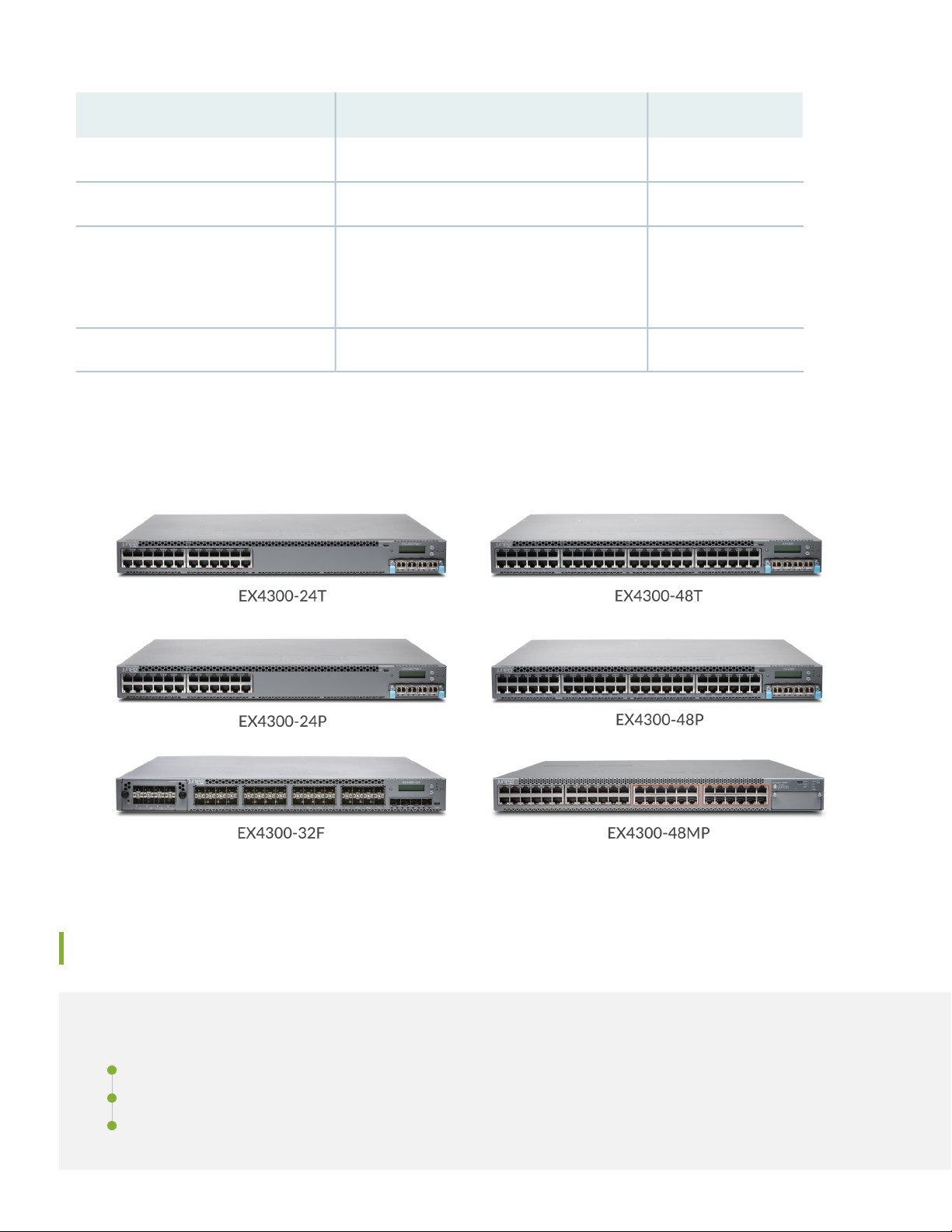
Meet the EX4300 Line of Ethernet Switches
The Juniper Networks®EX4300 Ethernet Switches are fixed-configuration platforms that can be deployed as standalone
systems or as part of a Virtual Chassis switching architecture. The EX4300 switches are available in 24-port, 32-port, and
48-port models, with or without PoE+, with AC or DC power supplies, and with different airflow directions. EX4300
switches also provide uplink ports and a slot for installing an optional uplink module.
PoE/PoE+ Ports10/100/1000BASE-T PortsModel
024EX4300-24T
2424EX4300-24P
Page 2
2
PoE/PoE+ Ports10/100/1000BASE-T PortsModel
048EX4300-48T
4848EX4300-48P
EX4300-48MP
(plus 24 100/1000/2500/5000/10000BASE-T
ports)
4824
032 100/1000BASE-X portsEX4300-32F
In this guide, we show you how to install an AC-powered EX4300 switch with the fan modules and power supplies
preinstalled. If you need instructions for installing fans, power supplies, and optional uplink modules, see the EX4300
Switch Hardware Guide.
Install the EX4300
IN THIS SECTION
What’s in the Box? | 3
What Else Do I Need? | 3
Install the EX4300 Switch in a Two-Post Rack | 3
Page 3

You can install the EX4300 switch on a table or desktop, on a wall, or in a two-post or four-post rack. The mounting kit
that ships in the box has the brackets you need to install the EX4300 switch in a two-post rack. We’ll walk you through
how to do that.
NOTE: If you want to install the switch on the wall or in a four-post rack, you’ll need to order separate mounting
kits. The four-post rack mount kit also has brackets for mounting the EX4300 switch in a recessed position in
the rack.
What’s in the Box?
EX4300 switch
•
An AC power cord appropriate for your geographical location
•
Two mounting brackets and eight mounting screws
•
An Ethernet cable with RJ-45 connectors attached and an RJ-45 to DB-9 serial port adapter
•
3
What Else Do I Need?
You’ll need to provide the following:
Four rack mount screws to secure the chassis to the rack
•
A number two Phillips (+) screwdriver
•
An electrostatic discharge (ESD) grounding strap
•
A management host such as a laptop or desktop PC
•
A serial-to-USB adapter (if your laptop or desktop PC doesn’t have a serial port)
•
Someone to help you secure the switch to the rack
•
Install the EX4300 Switch in a Two-Post Rack
1. Review General Safety Guidelines and Warnings
2. Wrap and fasten one end of the ESD grounding strap around your bare wrist, and connect the other end to a site ESD
point.
3. Attach the mounting brackets to the sides of the EX4300 switch using the eight screws and a screwdriver.
Page 4

You’ll notice there are three locations on the side panel where you can attach the mounting brackets: front, center,
g021433
g022543
g022544
g020094
Mounting rack
Mounting bracket
and rear. Attach the mounting brackets to the location that best suits where you want the EX4300 switch to sit in the
rack.
4
4. Lift the EX4300 switch and position it in the rack. Line up the bottom hole in each mounting bracket with a hole in
each rack rail, making sure the EX4300 switch is level.
Page 5

5. While you’re holding the EX4300 switch in place, have someone insert and tighten the rack mount screws to secure
the mounting brackets to the rack rails. Make sure to tighten the screws in the two bottom holes first and then tighten
the screws in the two top holes next.
6. Check that the mounting brackets on each side of the rack are level.
Power On
Now you’re ready to connect the EX4300 switch to a dedicated AC power source. The switch comes with the AC power
cord for your geographic location.
Here’s how to connect the EX4300 switch to AC power:
1. Wrap and fasten one end of an ESD wrist strap around your bare wrist, and connect the other end of the strap to the
ESD point on the switch.
2. On the rear panel, connect the retainer clip and power cord to the AC power socket (see Figure 1 and Figure 2):
5
a. Push the end of the retainer strip into the hole next to the AC power socket until it snaps into place.
b. Press the small tab on the retainer strip to loosen the loop.
c. Slide the loop until you have enough space to insert the power cord coupler into the AC power socket.
d. Plug in the power cord to the power socket on the switch.
e. Slide the loop toward the power supply until it is snug against the base of the coupler.
f. Press the tab on the loop and draw out the loop into a tight circle.
Figure 1: Connecting AC Power to an EX4300 Switch (Except the EX4300-48MP)
Page 6

Figure 2: Connecting Power to an EX4300-48MP Switch
g022468
3. If the AC power source outlet has a power switch, turn it off.
4. Plug in the AC power cord to the AC power source outlet.
6
5. If the AC power source outlet has a power switch, turn it on.
6. Check to see that the IN OK and the OUT OK LEDs on each power supply are lit green.
If the OUT OK LED is lit amber, turn off the AC power source outlet or unplug the switch. You’ll need to replace the
power supply. See Removing an AC Power Supply from an EX4300 System.
Step 2: Up and Running
IN THIS SECTION
Plug and Play | 7
Customize the Basic Configuration | 7
Now that the EX4300 switch is powered on, let’s do some initial configuration to get the switch up and running on your
network. It’s simple to provision and manage the EX4300 switch and other devices on your network. Choose the
configuration tool that’s right for you:
Juniper Mist. To use Mist, you’ll need an account on the Mist Cloud Platform. See Overview of Connecting Mist Access
•
Points and Juniper EX Series Switches.
Page 7

Juniper Networks Contrail Service Orchestration (CSO). To use CSO, you’ll need an authentication code. See SD-WAN
•
Deployment Overview in the Contrail Service Orchestration (CSO) Deployment Guide.
CLI commands
•
Plug and Play
The EX4300 switches already have factory-default settings configured right out of the box to make them plug-and-play
devices. The default settings are stored in a configuration file that:
Sets values for system parameters such as syslog and commit
•
Configures Ethernet switching on all interfaces
•
Enables IGMP snooping
•
Enables the LLDP and RSTP protocols
•
These settings load as soon as you power on the EX4300 switch. If you want to see what’s in the factory-default
configuration file for your EX4300 switch, see EX4300 Switch Default Configuration.
7
Customize the Basic Configuration
You can easily customize the basic configuration using the EZSetup wizard. When you commit changes in the EZSetup
wizard, a new configuration file is created. This becomes the active configuration. You can always revert to the
factory-default configuration whenever you want.
NOTE: To run the EZSetup wizard, the EX4300 switch must have the factory-default configuration as the active
configuration. If you have configured anything on the switch and want to run EZSetup, you’ll need to revert to
the factory-default configuration. See Reverting to the Default Factory Configuration for the EX Series Switch.
Have these values handy before you begin configuring custom settings for the switch:
Hostname
•
Root authentication password
•
Management port IP address
•
Default gateway IP address
•
(Optional) SNMP read community, location, and contact information
•
Page 8

1. Verify that the serial port settings for your laptop or desktop PC are set to the default:
Baud rate—9600
•
Flow control—None
•
Data—8
•
Parity—None
•
Stop bits—1
•
DCD state—Disregard
•
2. Connect the console port on the EX4300 switch to a laptop or desktop PC using the Ethernet cable and the RJ-45 to
DB-9 serial port adapter that came in the box with the switch.
NOTE: If your laptop or desktop PC doesn't have a serial port, use a serial-to-USB adapter (not provided).
3. At the Junos OS login prompt, type root to log in.
8
4. Type ezsetup to initiate the EZSetup wizard.
5. (Optional) Type the system hostname.
6. Type the new root password that you want to use for the EX4300 switch. Reenter the password when prompted.
7. Type yes to enable Telnet service.
8. Type yes to enable SSH service.
NOTE: You can’t log in as the root user when Telnet is enabled for the MGMT port. You can only log in as
the root user through SSH.
9. Choose in-band management [Option 1]. This is the default.
10. Choose Use VLAN “default” for management [Option 1]. When you use the Default VLAN, all devices you connect to
the switch will be placed into this VLAN. They can begin transmitting traffic on the network without further switch
configuration.
11. Type the management port IP address.
12. Type the submask.
13. Type the gateway IP address.
Page 9

14. (Optional) Configure SNMP settings and the time zone.
15. When the configured parameters are shown on the screen, type yes to commit the new configuration. This becomes
the active configuration for the EX4300 switch.
You can now log in to the EX4300 switch with the CLI and continue customizing the configuration.
Step 3: Keep Going
Congratulations! Now that you’ve done the initial configuration, your EX4300 switch is ready to use.
Here are some things you can do next:
ThenIf you want to
9
Download, activate, and manage your software licenses to unlock
additional features for your EX series switch
See all documentation available for the EX4300 switch
Find more in-depth information about installing and configuring the
EX4300 switch
Manage software upgrades on your EX Series switch
issues
See Activate Junos OS Licenses in the
Juniper Licensing Guide
Visit EX4300 Documentation in the Juniper
Networks TechLibrary
Browse through the EX4300 Switch
Hardware Guide
See Installing Software on EX Series
Switches
Visit the Security Design CenterSee, automate, and protect your network with Juniper Security
See the Junos OS Release NotesStay up-to-date about new and changed features and known and resolved
Juniper Networks, the Juniper Networks logo, Juniper, and Junos are registered trademarks of Juniper Networks, Inc. in the
United States and other countries. All other trademarks, service marks, registered marks, or registered service marks are the
property of their respective owners. Juniper Networks assumes no responsibility for any inaccuracies in this document. Juniper
Networks reserves the right to change, modify, transfer, or otherwise revise this publication without notice. Copyright © 2021
Juniper Networks, Inc. All rights reserved. Rev. 02, March 2021.
 Loading...