

Juniper EX2200 Series, EX2200-C-12T-2G, EX2200-C-12P-2G, EX2200-24T-4G, EX2200-24P-4G Hardware Manual
...Page 1

Complete Hardware Guide for EX2200 Ethernet
Switches
Published: 2011-11-15
Revision 7
Copyright © 2011, Juniper Networks, Inc.
Page 2

Juniper Networks, Inc.
1194 North Mathilda Avenue
Sunnyvale, California 94089
USA
408-745-2000
www.juniper.net
This productincludes the EnvoySNMPEngine, developed byEpilogue Technology, an IntegratedSystemsCompany.Copyright © 1986-1997,
Epilogue Technology Corporation. All rights reserved. This program and its documentation were developed at private expense, and no part
of them is in the public domain.
This product includes memory allocation software developed by Mark Moraes, copyright © 1988, 1989, 1993, University of Toronto.
This product includes FreeBSD software developed by the University of California, Berkeley, and its contributors. All of the documentation
and software included in the 4.4BSD and 4.4BSD-Lite Releases is copyrighted by the Regents of the University of California. Copyright ©
1979, 1980, 1983, 1986, 1988, 1989, 1991, 1992, 1993, 1994. The Regents of the University of California. All rights reserved.
GateD software copyright © 1995, the Regents of the University. All rights reserved. Gate Daemon was originated and developed through
release 3.0 by Cornell University and its collaborators. Gated is based on Kirton’s EGP, UC Berkeley’s routing daemon (routed), and DCN’s
HELLO routing protocol. Development of Gated has been supported in part by the National Science Foundation. Portions of the GateD
software copyright © 1988, Regents of the University of California. All rights reserved. Portions of the GateD software copyright © 1991, D.
L. S. Associates.
This product includes software developed by Maker Communications, Inc., copyright © 1996, 1997, Maker Communications, Inc.
Juniper Networks, Junos, Steel-Belted Radius, NetScreen, and ScreenOS are registered trademarks of Juniper Networks, Inc. in the United
States and other countries. The Juniper Networks Logo, the Junos logo, and JunosE are trademarks of Juniper Networks, Inc. All other
trademarks, service marks, registered trademarks, or registered service marks are the property of their respective owners.
Juniper Networks assumes no responsibility for any inaccuracies in this document. Juniper Networks reserves the right to change, modify,
transfer, or otherwise revise this publication without notice.
Products made or sold by Juniper Networks or components thereof might be covered by one or more of the following patents that are
owned by or licensed to Juniper Networks: U.S. Patent Nos. 5,473,599, 5,905,725, 5,909,440, 6,192,051, 6,333,650, 6,359,479, 6,406,312,
6,429,706, 6,459,579, 6,493,347, 6,538,518, 6,538,899, 6,552,918, 6,567,902, 6,578,186, and 6,590,785.
Complete Hardware Guide for EX2200 Ethernet Switches
Copyright © 2011, Juniper Networks, Inc.
All rights reserved.
Revision History
17 February 2010—Revision 1
May 2010—Revision 2
August 2010—Revision 3
December 2010—Revision 4
March 2011—Revision 5
July 2011—Revision 6
September 2011—Revision 7
November 2011—Revision 8
The information in this document is current as of the date listed in the revision history.
YEAR 2000 NOTICE
Juniper Networks hardware and software products are Year 2000 compliant. Junos OS has no known time-related limitations through the
year 2038. However, the NTP application is known to have some difficulty in the year 2036.
SOFTWARE LICENSE
The terms and conditions for using this software are described in the software license contained in the acknowledgment to your purchase
order or, to the extent applicable, to any reseller agreement or end-user purchase agreement executed between you and Juniper Networks.
By using this software, you indicate that you understand and agree to be bound by those terms and conditions.
Copyright © 2011, Juniper Networks, Inc.ii
Page 3

Generally speaking, the software license restricts the manner in which you are permitted to use the software and may contain prohibitions
against certain uses. The software license may state conditions under which the license is automatically terminated. You should consult
the license for further details.
For complete product documentation, please see the Juniper Networks Web site at www.juniper.net/techpubs.
END USER LICENSE AGREEMENT
The Juniper Networks product that is the subject of this technical documentation consists of (or is intended for use with) Juniper Networks
software. Use of such software is subject to the terms and conditions of the End User License Agreement (“EULA”) posted at
http://www.juniper.net/support/eula.html. By downloading, installing or using such software, you agree to the terms and conditions
of that EULA.
iiiCopyright © 2011, Juniper Networks, Inc.
Page 4

Copyright © 2011, Juniper Networks, Inc.iv
Page 5

Table of Contents
About This Topic Collection . . . . . . . . . . . . . . . . . . . . . . . . . . . . . . . . . . . . . . . . . xv
How to Use This Guide . . . . . . . . . . . . . . . . . . . . . . . . . . . . . . . . . . . . . . . . . . . . . . . xv
List of EX Series Guides for Junos OS Release 11.4 . . . . . . . . . . . . . . . . . . . . . . . . . xv
Downloading Software . . . . . . . . . . . . . . . . . . . . . . . . . . . . . . . . . . . . . . . . . . . . . . xvii
Documentation Symbols Key . . . . . . . . . . . . . . . . . . . . . . . . . . . . . . . . . . . . . . . . xviii
Documentation Feedback . . . . . . . . . . . . . . . . . . . . . . . . . . . . . . . . . . . . . . . . . . . . xix
Requesting Technical Support . . . . . . . . . . . . . . . . . . . . . . . . . . . . . . . . . . . . . . . . . xx
Self-Help Online Tools and Resources . . . . . . . . . . . . . . . . . . . . . . . . . . . . . . . xx
Opening a Case with JTAC . . . . . . . . . . . . . . . . . . . . . . . . . . . . . . . . . . . . . . . . . xx
Part 1 Switch and Components Overview and Specifications
Chapter 1 EX2200 Switch Overview . . . . . . . . . . . . . . . . . . . . . . . . . . . . . . . . . . . . . . . . . . . 3
EX2200 Switches Hardware Overview . . . . . . . . . . . . . . . . . . . . . . . . . . . . . . . . . . . 3
EX2200 Switches First View . . . . . . . . . . . . . . . . . . . . . . . . . . . . . . . . . . . . . . . . 3
Uplink Ports . . . . . . . . . . . . . . . . . . . . . . . . . . . . . . . . . . . . . . . . . . . . . . . . . . . . . 4
Console Port . . . . . . . . . . . . . . . . . . . . . . . . . . . . . . . . . . . . . . . . . . . . . . . . . . . . 4
Cable Guard . . . . . . . . . . . . . . . . . . . . . . . . . . . . . . . . . . . . . . . . . . . . . . . . . . . . 4
Security Slots . . . . . . . . . . . . . . . . . . . . . . . . . . . . . . . . . . . . . . . . . . . . . . . . . . . 4
Power over Ethernet (PoE) Ports . . . . . . . . . . . . . . . . . . . . . . . . . . . . . . . . . . . . 5
Front Panel of an EX2200 Switch . . . . . . . . . . . . . . . . . . . . . . . . . . . . . . . . . . . 5
Rear Panel of an EX2200 Switch . . . . . . . . . . . . . . . . . . . . . . . . . . . . . . . . . . . . 7
EX2200 Switch Models . . . . . . . . . . . . . . . . . . . . . . . . . . . . . . . . . . . . . . . . . . . . . . . 8
Chassis Physical Specifications for EX2200 Switches . . . . . . . . . . . . . . . . . . . . . . . 9
EX2200 Switch Hardware and CLI Terminology Mapping . . . . . . . . . . . . . . . . . . . 10
Chapter 2 Component Descriptions . . . . . . . . . . . . . . . . . . . . . . . . . . . . . . . . . . . . . . . . . . . 13
Chassis Status LEDs in EX2200 Switches . . . . . . . . . . . . . . . . . . . . . . . . . . . . . . . . 13
Network Port and Uplink Port LEDs in EX2200 Switches . . . . . . . . . . . . . . . . . . . . 14
Management Port LEDs in EX2200 Switches . . . . . . . . . . . . . . . . . . . . . . . . . . . . . 17
Power Supply in EX2200 Switches . . . . . . . . . . . . . . . . . . . . . . . . . . . . . . . . . . . . . 18
Cooling System and Airflow in an EX2200 Switch . . . . . . . . . . . . . . . . . . . . . . . . . 19
Chapter 3 Component Specifications . . . . . . . . . . . . . . . . . . . . . . . . . . . . . . . . . . . . . . . . . 21
USB Port Specifications for an EX Series Switch . . . . . . . . . . . . . . . . . . . . . . . . . . . 21
Mini-USB Port Specifications for an EX2200 Switch . . . . . . . . . . . . . . . . . . . . . . . 22
Network Port Connector Pinout Information for an EX2200 Switch . . . . . . . . . . . 23
Console Port Connector Pinout Information for an EX Series Switch . . . . . . . . . . 23
Management Port Connector Pinout Information for an EX2200 Switch . . . . . . . 24
Optical Interface Support in EX2200 Switches . . . . . . . . . . . . . . . . . . . . . . . . . . . 25
vCopyright © 2011, Juniper Networks, Inc.
Page 6

Complete Hardware Guide for EX2200 Ethernet Switches
Part 2 Planning for Switch Installation
Chapter 4 Site Preparation . . . . . . . . . . . . . . . . . . . . . . . . . . . . . . . . . . . . . . . . . . . . . . . . . . . 51
Site Preparation Checklist for EX2200 Switches . . . . . . . . . . . . . . . . . . . . . . . . . . . 51
General Site Guidelines . . . . . . . . . . . . . . . . . . . . . . . . . . . . . . . . . . . . . . . . . . . . . . 52
Site Electrical Wiring Guidelines . . . . . . . . . . . . . . . . . . . . . . . . . . . . . . . . . . . . . . . 53
Environmental Requirements and Specifications for EX Series Switches . . . . . . . 54
Chapter 5 Mounting and Clearance Requirements . . . . . . . . . . . . . . . . . . . . . . . . . . . . . . 57
Rack Requirements for EX2200 Switches . . . . . . . . . . . . . . . . . . . . . . . . . . . . . . . . 57
Cabinet Requirements for EX2200 Switches . . . . . . . . . . . . . . . . . . . . . . . . . . . . . 58
Requirements for Mounting an EX2200 Switch on a Desktop or Wall . . . . . . . . . 60
Clearance Requirements for Airflow and Hardware Maintenance for EX2200
Switches . . . . . . . . . . . . . . . . . . . . . . . . . . . . . . . . . . . . . . . . . . . . . . . . . . . . . . 60
Chapter 6 Cable Specifications . . . . . . . . . . . . . . . . . . . . . . . . . . . . . . . . . . . . . . . . . . . . . . 63
Network Cable Specifications for EX2200 Switches . . . . . . . . . . . . . . . . . . . . . . . 63
Chapter 7 Planning Power Requirements . . . . . . . . . . . . . . . . . . . . . . . . . . . . . . . . . . . . . . 65
Power Specifications for EX2200 Switches . . . . . . . . . . . . . . . . . . . . . . . . . . . . . . 65
AC Power Cord Specifications for EX2200 Switches . . . . . . . . . . . . . . . . . . . . . . . 66
Part 3 Installing and Connecting the Switch and Switch Components
Chapter 8 Installing the Switch . . . . . . . . . . . . . . . . . . . . . . . . . . . . . . . . . . . . . . . . . . . . . . . 71
Installing and Connecting an EX2200 Switch . . . . . . . . . . . . . . . . . . . . . . . . . . . . . 71
Unpacking an EX2200 Switch . . . . . . . . . . . . . . . . . . . . . . . . . . . . . . . . . . . . . . . . . 72
Parts Inventory (Packing List) for an EX2200 Switch . . . . . . . . . . . . . . . . . . . . . . . 73
Mounting an EX2200 Switch . . . . . . . . . . . . . . . . . . . . . . . . . . . . . . . . . . . . . . . . . . 74
Mounting an EX2200 Switch on a Desk or Other Level Surface . . . . . . . . . . . . . . . 75
Mounting an EX2200 Switch On or Under a Desk Using Screws . . . . . . . . . . . . . . 78
Mounting an EX2200 Switch on Two Posts of a Rack or Cabinet . . . . . . . . . . . . . 81
Mounting an EX2200 Switch on Four Posts of a Rack or Cabinet . . . . . . . . . . . . . 84
Mounting an EX2200 Switch in a Recessed Position in a Rack or Cabinet . . . . . . 88
Mounting an EX2200 Switch on a Wall . . . . . . . . . . . . . . . . . . . . . . . . . . . . . . . . . 88
Mounting an EX2200 Switch Except the EX2200-C Model on a Wall . . . . . . 88
Mounting an EX2200-C Switch on a Wall . . . . . . . . . . . . . . . . . . . . . . . . . . . . 91
Mounting an EX2200 Switch Using the Magnet Mount . . . . . . . . . . . . . . . . . . . . . 94
Chapter 9 Installing Switch Components . . . . . . . . . . . . . . . . . . . . . . . . . . . . . . . . . . . . . . 99
Installing a Transceiver in an EX Series Switch . . . . . . . . . . . . . . . . . . . . . . . . . . . . 99
Chapter 10 Connecting the Switch . . . . . . . . . . . . . . . . . . . . . . . . . . . . . . . . . . . . . . . . . . . . 103
Connecting Earth Ground to an EX Series Switch . . . . . . . . . . . . . . . . . . . . . . . . . 103
Connecting Earth Ground to an EX2200, EX3200, or EX3300 Switch . . . . . 104
Connecting Earth Ground to an EX4500 Switch . . . . . . . . . . . . . . . . . . . . . . 105
Connecting Earth Ground to an EX6210 Switch . . . . . . . . . . . . . . . . . . . . . . 106
Connecting Earth Ground to an EX8208 Switch . . . . . . . . . . . . . . . . . . . . . . 107
Connecting Earth Ground to an EX8216 Switch . . . . . . . . . . . . . . . . . . . . . . . 108
Connecting AC Power to an EX2200 Switch . . . . . . . . . . . . . . . . . . . . . . . . . . . . . 109
Connecting DC Power to an EX2200 Switch . . . . . . . . . . . . . . . . . . . . . . . . . . . . . 110
Copyright © 2011, Juniper Networks, Inc.vi
Page 7

Table of Contents
Connecting an EX Series Switch to a Network for Out-of-Band Management . . . 113
Connecting an EX Series Switch to a Management Console . . . . . . . . . . . . . . . . . 115
Connecting an EX Series Switch to a Management Console Using RJ-45
Console Port . . . . . . . . . . . . . . . . . . . . . . . . . . . . . . . . . . . . . . . . . . . . . . . 115
Connecting an EX2200 Switch to a Management Console Using Mini-USB
Type-B Console Port . . . . . . . . . . . . . . . . . . . . . . . . . . . . . . . . . . . . . . . . . 117
Connecting an EX Series Switch to a Modem . . . . . . . . . . . . . . . . . . . . . . . . . . . . . 117
Setting the Serial Console Speed for the Switch . . . . . . . . . . . . . . . . . . . . . . 118
Configuring the Modem . . . . . . . . . . . . . . . . . . . . . . . . . . . . . . . . . . . . . . . . . . 119
Connecting the Modem to the Console Port . . . . . . . . . . . . . . . . . . . . . . . . . 120
Connecting a Fiber-Optic Cable to an EX Series Switch . . . . . . . . . . . . . . . . . . . . 121
Chapter 11 Performing Initial Configuration . . . . . . . . . . . . . . . . . . . . . . . . . . . . . . . . . . . . 125
EX2200 Switch Default Configuration . . . . . . . . . . . . . . . . . . . . . . . . . . . . . . . . . . 125
Connecting and Configuring an EX Series Switch (CLI Procedure) . . . . . . . . . . . 129
Connecting and Configuring an EX Series Switch (J-Web Procedure) . . . . . . . . . 131
Part 4 Removing Switch Components
Chapter 12 Removing Switch Components . . . . . . . . . . . . . . . . . . . . . . . . . . . . . . . . . . . . . 137
Removing a Transceiver from an EX Series Switch . . . . . . . . . . . . . . . . . . . . . . . . 137
Disconnecting a Fiber-Optic Cable from an EX Series Switch . . . . . . . . . . . . . . . 139
Part 5 Switch and Component Maintenance
Chapter 13 Routine Maintenance . . . . . . . . . . . . . . . . . . . . . . . . . . . . . . . . . . . . . . . . . . . . . 143
Maintaining Fiber-Optic Cables in EX Series Switches . . . . . . . . . . . . . . . . . . . . . 143
Part 6 Returning Hardware
Chapter 14 Returning the Switch or Switch Components . . . . . . . . . . . . . . . . . . . . . . . . 147
Returning an EX2200 Switch or Component for Repair or Replacement . . . . . . . 147
Locating the Serial Number on an EX2200 Switch or Component . . . . . . . . . . . 148
Listing the Switch and Components Details with the CLI . . . . . . . . . . . . . . . 148
Locating the Chassis Serial Number ID Label on an EX2200 Switch . . . . . . 148
Contacting Customer Support to Obtain Return Materials Authorization for EX
Series Switches . . . . . . . . . . . . . . . . . . . . . . . . . . . . . . . . . . . . . . . . . . . . . . . . 149
Packing an EX2200 Switch or Component for Shipping . . . . . . . . . . . . . . . . . . . 150
Packing a Switch for Shipping . . . . . . . . . . . . . . . . . . . . . . . . . . . . . . . . . . . . . 151
Packing Switch Components for Shipping . . . . . . . . . . . . . . . . . . . . . . . . . . . 152
Part 7 Safety Information
Chapter 15 General Safety Information . . . . . . . . . . . . . . . . . . . . . . . . . . . . . . . . . . . . . . . . 155
General Safety Guidelines and Warnings . . . . . . . . . . . . . . . . . . . . . . . . . . . . . . . . 155
Definitions of Safety Warning Levels . . . . . . . . . . . . . . . . . . . . . . . . . . . . . . . . . . . 156
Fire Safety Requirements . . . . . . . . . . . . . . . . . . . . . . . . . . . . . . . . . . . . . . . . . . . . 158
Qualified Personnel Warning . . . . . . . . . . . . . . . . . . . . . . . . . . . . . . . . . . . . . . . . . 159
Warning Statement for Norway and Sweden . . . . . . . . . . . . . . . . . . . . . . . . . . . . 160
viiCopyright © 2011, Juniper Networks, Inc.
Page 8

Complete Hardware Guide for EX2200 Ethernet Switches
Chapter 16 Radiation and Laser Warnings . . . . . . . . . . . . . . . . . . . . . . . . . . . . . . . . . . . . . . 161
Laser and LED Safety Guidelines and Warnings for EX Series Switches . . . . . . . . 161
General Laser Safety Guidelines . . . . . . . . . . . . . . . . . . . . . . . . . . . . . . . . . . . 161
Class 1 Laser Product Warning . . . . . . . . . . . . . . . . . . . . . . . . . . . . . . . . . . . . . 161
Laser Beam Warning . . . . . . . . . . . . . . . . . . . . . . . . . . . . . . . . . . . . . . . . . . . . 162
Radiation from Open Port Apertures Warning . . . . . . . . . . . . . . . . . . . . . . . . . . . . 163
Chapter 17 Installation and Maintenance Safety Information . . . . . . . . . . . . . . . . . . . . 165
Installation Instructions Warning . . . . . . . . . . . . . . . . . . . . . . . . . . . . . . . . . . . . . . 165
Chassis Lifting Guidelines for EX2200 Switches . . . . . . . . . . . . . . . . . . . . . . . . . . 166
Ramp Warning . . . . . . . . . . . . . . . . . . . . . . . . . . . . . . . . . . . . . . . . . . . . . . . . . . . . 167
Rack-Mounting and Cabinet-Mounting Warnings . . . . . . . . . . . . . . . . . . . . . . . . . 167
Wall-Mounting Warnings for EX2200 Switches . . . . . . . . . . . . . . . . . . . . . . . . . . . 171
Grounded Equipment Warning . . . . . . . . . . . . . . . . . . . . . . . . . . . . . . . . . . . . . . . . 172
Maintenance and Operational Safety Guidelines and Warnings . . . . . . . . . . . . . . 172
Jewelry Removal Warning . . . . . . . . . . . . . . . . . . . . . . . . . . . . . . . . . . . . . . . . 173
Lightning Activity Warning . . . . . . . . . . . . . . . . . . . . . . . . . . . . . . . . . . . . . . . . 174
Operating Temperature Warning . . . . . . . . . . . . . . . . . . . . . . . . . . . . . . . . . . . 175
Product Disposal Warning . . . . . . . . . . . . . . . . . . . . . . . . . . . . . . . . . . . . . . . . 176
Chapter 18 Power and Electrical Safety Information . . . . . . . . . . . . . . . . . . . . . . . . . . . . 179
General Electrical Safety Guidelines and Warnings . . . . . . . . . . . . . . . . . . . . . . . . 179
Prevention of Electrostatic Discharge Damage . . . . . . . . . . . . . . . . . . . . . . . . . . . 180
AC Power Electrical Safety Guidelines . . . . . . . . . . . . . . . . . . . . . . . . . . . . . . . . . . 182
AC Power Disconnection Warning . . . . . . . . . . . . . . . . . . . . . . . . . . . . . . . . . . . . . 183
DC Power Electrical Safety Guidelines . . . . . . . . . . . . . . . . . . . . . . . . . . . . . . . . . 184
DC Power Disconnection Warning . . . . . . . . . . . . . . . . . . . . . . . . . . . . . . . . . . . . . 186
DC Power Grounding Requirements and Warning . . . . . . . . . . . . . . . . . . . . . . . . 188
DC Power Wiring Sequence Warning . . . . . . . . . . . . . . . . . . . . . . . . . . . . . . . . . . . 189
DC Power Wiring Terminations Warning . . . . . . . . . . . . . . . . . . . . . . . . . . . . . . . . 190
TN Power Warning . . . . . . . . . . . . . . . . . . . . . . . . . . . . . . . . . . . . . . . . . . . . . . . . . 192
Action to Take After an Electrical Accident . . . . . . . . . . . . . . . . . . . . . . . . . . . . . . 192
Part 8 Compliance Information
Chapter 19 Compliance Information . . . . . . . . . . . . . . . . . . . . . . . . . . . . . . . . . . . . . . . . . . 197
Agency Approvals for EX Series Switches . . . . . . . . . . . . . . . . . . . . . . . . . . . . . . . 197
Compliance Statements for EMC Requirements for EX Series Switches . . . . . . . 198
Compliance Statements for Acoustic Noise for EX Series Switches . . . . . . . . . . 201
Declaration of Conformity for EX2200 Switches . . . . . . . . . . . . . . . . . . . . . . . . . 202
Canada . . . . . . . . . . . . . . . . . . . . . . . . . . . . . . . . . . . . . . . . . . . . . . . . . . . . . . 198
European Community . . . . . . . . . . . . . . . . . . . . . . . . . . . . . . . . . . . . . . . . . . . 199
Japan . . . . . . . . . . . . . . . . . . . . . . . . . . . . . . . . . . . . . . . . . . . . . . . . . . . . . . . . 199
Korea . . . . . . . . . . . . . . . . . . . . . . . . . . . . . . . . . . . . . . . . . . . . . . . . . . . . . . . . 199
United States . . . . . . . . . . . . . . . . . . . . . . . . . . . . . . . . . . . . . . . . . . . . . . . . . 200
FCC Part 15 Statement . . . . . . . . . . . . . . . . . . . . . . . . . . . . . . . . . . . . . . . . . . 200
Non-Regulatory Environmental Standards . . . . . . . . . . . . . . . . . . . . . . . . . . 200
Copyright © 2011, Juniper Networks, Inc.viii
Page 9

List of Figures
Part 1 Switch and Components Overview and Specifications
Chapter 1 EX2200 Switch Overview . . . . . . . . . . . . . . . . . . . . . . . . . . . . . . . . . . . . . . . . . . . 3
Figure 1: Front Panel of an EX2200 Switch with 48 Gigabit Ethernet Ports . . . . . . 6
Figure 2: Front Panel of an EX2200 Switch with 24 Gigabit Ethernet Ports . . . . . . 6
Figure 3: Front Panel of an EX2200-C Switch with 12 Gigabit Ethernet Ports
(PoE+) . . . . . . . . . . . . . . . . . . . . . . . . . . . . . . . . . . . . . . . . . . . . . . . . . . . . . . . . . 7
Figure 4: Front Panel of an EX2200-C Switch with 12 Gigabit Ethernet Ports
(non-PoE) . . . . . . . . . . . . . . . . . . . . . . . . . . . . . . . . . . . . . . . . . . . . . . . . . . . . . . 7
Figure 5: Rear Panel of an EX2200 Switch With an AC Power Supply . . . . . . . . . . . 8
Figure 6: Rear Panel of an EX2200-C-12P Switch with Heatsink . . . . . . . . . . . . . . . 8
Chapter 2 Component Descriptions . . . . . . . . . . . . . . . . . . . . . . . . . . . . . . . . . . . . . . . . . . . 13
Figure 7: Chassis Status LEDs in an EX2200 Switch Except the EX2200-C
Switch . . . . . . . . . . . . . . . . . . . . . . . . . . . . . . . . . . . . . . . . . . . . . . . . . . . . . . . . . 13
Figure 8: Chassis Status LEDs in an EX2200-C Switch . . . . . . . . . . . . . . . . . . . . . . 13
Figure 9: LEDs on the Network Port . . . . . . . . . . . . . . . . . . . . . . . . . . . . . . . . . . . . . 14
Figure 10: LEDs on the Uplink Ports and Port Status Mode LEDs in an EX2200
Switch Except the EX2200-C Switch Model . . . . . . . . . . . . . . . . . . . . . . . . . . 15
Figure11: Port status mode LEDs of the Dual-purpose uplink Ports of an EX2200-C
Switch . . . . . . . . . . . . . . . . . . . . . . . . . . . . . . . . . . . . . . . . . . . . . . . . . . . . . . . . 15
Figure 12: LEDs on the Management Port on an EX2200 Switch Except the
EX2200-C Switch Model . . . . . . . . . . . . . . . . . . . . . . . . . . . . . . . . . . . . . . . . . . 17
Figure 13: LEDs on the Management Port on an EX2200-C Switch . . . . . . . . . . . . 17
Figure 14: Airflow Through Non-PoE Models of EX2200 Switches Except the
EX2200-C Switch Model . . . . . . . . . . . . . . . . . . . . . . . . . . . . . . . . . . . . . . . . . . 19
Figure15: Airflow Through PoEModels of EX2200 SwitchesExceptthe EX2200-C
Switch Models . . . . . . . . . . . . . . . . . . . . . . . . . . . . . . . . . . . . . . . . . . . . . . . . . 20
Part 2 Planning for Switch Installation
Chapter 5 Mounting and Clearance Requirements . . . . . . . . . . . . . . . . . . . . . . . . . . . . . . 57
Figure 16: Clearance Requirements for Airflow and Hardware Maintenance for
Figure 17: Clearance Requirements for Airflow and Hardware Maintenance for
Figure 18: Airflow Through PoE Models of EX2200 Switches Except EX2200-C
Figure 19: Airflow Through Non-PoE Models of EX2200 Switches Except
Chapter 7 Planning Power Requirements . . . . . . . . . . . . . . . . . . . . . . . . . . . . . . . . . . . . . . 65
EX2200 Switches Except EX2200-C Switch Models . . . . . . . . . . . . . . . . . . . 60
EX2200-C Switch Models . . . . . . . . . . . . . . . . . . . . . . . . . . . . . . . . . . . . . . . . . 61
Switch Models . . . . . . . . . . . . . . . . . . . . . . . . . . . . . . . . . . . . . . . . . . . . . . . . . . 61
EX2200-C Switch Models . . . . . . . . . . . . . . . . . . . . . . . . . . . . . . . . . . . . . . . . 62
ixCopyright © 2011, Juniper Networks, Inc.
Page 10

Complete Hardware Guide for EX2200 Ethernet Switches
Figure 20: AC Plug Types . . . . . . . . . . . . . . . . . . . . . . . . . . . . . . . . . . . . . . . . . . . . . 67
Part 3 Installing and Connecting the Switch and Switch Components
Chapter 8 Installing the Switch . . . . . . . . . . . . . . . . . . . . . . . . . . . . . . . . . . . . . . . . . . . . . . . 71
Figure 21: Attaching Rubber Feet to a Switch Chassis . . . . . . . . . . . . . . . . . . . . . . 76
Figure 22: Attaching a Cable Guard to an EX2200-C Switch . . . . . . . . . . . . . . . . . 77
Figure 23: Securing the EX2200-C Switch Using Security Slots . . . . . . . . . . . . . . . 77
Figure 24: Measurements for Installing Mounting Screws for EX2200-C
Switch . . . . . . . . . . . . . . . . . . . . . . . . . . . . . . . . . . . . . . . . . . . . . . . . . . . . . . . . 79
Figure 25: Mounting the EX2200-C Switch On or Under a Desk Using Screws . . 80
Figure 26: Attaching a Cable Guard to an EX2200-C Switch . . . . . . . . . . . . . . . . . 81
Figure 27: Securing the EX2200-C Switch Using Security Slots . . . . . . . . . . . . . . . 81
Figure 28: Attaching the Mounting Bracket Along the Front of the Switch . . . . . . 83
Figure 29: Mounting the Switch on Two Posts of a Rack . . . . . . . . . . . . . . . . . . . . 84
Figure 30: Attaching the Front Bracket to the Side-Rail Bracket . . . . . . . . . . . . . . 86
Figure 31: Attaching the Side-Rail Bracket to the Switch Chassis . . . . . . . . . . . . . 86
Figure 32: Mounting the Switch to the Front Posts of a Rack . . . . . . . . . . . . . . . . . 87
Figure 33: Sliding the Rear Brackets to the Rear of a Four-Post Rack . . . . . . . . . . 87
Figure 34: Attaching Wall-Mount Brackets to a Switch Chassis . . . . . . . . . . . . . . 89
Figure 35: Measurements for Installing Mounting Screws . . . . . . . . . . . . . . . . . . . 90
Figure 36: Mounting the Switch on a Wall . . . . . . . . . . . . . . . . . . . . . . . . . . . . . . . . 91
Figure 37: Measurements for Installing Mounting Screws for the EX2200-C
Switch . . . . . . . . . . . . . . . . . . . . . . . . . . . . . . . . . . . . . . . . . . . . . . . . . . . . . . . . 92
Figure 38: Mounting the EX2200-C Switch on a Wall Using Screws . . . . . . . . . . . 93
Figure 39: Attaching a Cable Guard to an EX2200-C Switch . . . . . . . . . . . . . . . . . 93
Figure 40: Securing the EX2200-C Switch Using Security Slots . . . . . . . . . . . . . . 94
Figure 41: Mounting an EX2200-C Switch Using Magnet Mount . . . . . . . . . . . . . . 96
Figure 42: Attaching a Cable Guard to an EX2200-C Switch . . . . . . . . . . . . . . . . . 97
Figure 43: Securing the EX2200-C Switch Using Security Slots . . . . . . . . . . . . . . 97
Chapter 9 Installing Switch Components . . . . . . . . . . . . . . . . . . . . . . . . . . . . . . . . . . . . . . 99
Figure 44: Installing a Transceiver in an EX Series Switch . . . . . . . . . . . . . . . . . . 100
Chapter 10 Connecting the Switch . . . . . . . . . . . . . . . . . . . . . . . . . . . . . . . . . . . . . . . . . . . . 103
Figure 45: Connecting a Grounding Cable to an EX Series Switch . . . . . . . . . . . . 103
Figure 46: Location of Protective Earthing Terminal on an EX6210 Switch . . . . . 106
Figure 47: Connecting an AC Power Cord Retainer Clip to the AC Power Cord
Inlet on an EX2200 Switch . . . . . . . . . . . . . . . . . . . . . . . . . . . . . . . . . . . . . . . 110
Figure 48: Connecting an AC Power Cord to the AC Power Cord Inlet on an
EX2200 Switch . . . . . . . . . . . . . . . . . . . . . . . . . . . . . . . . . . . . . . . . . . . . . . . . . 110
Figure 49: Securing Ring Lugs to the Terminals on the DC Power Supply . . . . . . . 112
Figure 50: Ethernet Cable Connector . . . . . . . . . . . . . . . . . . . . . . . . . . . . . . . . . . . 114
Figure 51: Connecting an EX Series Switch to a Network for Out-of-Band
Management . . . . . . . . . . . . . . . . . . . . . . . . . . . . . . . . . . . . . . . . . . . . . . . . . . 114
Figure 52: Ethernet Cable Connector . . . . . . . . . . . . . . . . . . . . . . . . . . . . . . . . . . . 115
Figure 53: Connecting an EX Series Switch to a Management Console Through
a Console Server . . . . . . . . . . . . . . . . . . . . . . . . . . . . . . . . . . . . . . . . . . . . . . . . 116
Figure 54: Connecting an EX Series Switch Directly to a Management
Console . . . . . . . . . . . . . . . . . . . . . . . . . . . . . . . . . . . . . . . . . . . . . . . . . . . . . . . 117
Copyright © 2011, Juniper Networks, Inc.x
Page 11

List of Figures
Figure 55: Ethernet Cable Connector . . . . . . . . . . . . . . . . . . . . . . . . . . . . . . . . . . . 120
Figure 56: Connecting a Fiber-Optic Cable to an Optical Transceiver Installed in
an EX Series Switch . . . . . . . . . . . . . . . . . . . . . . . . . . . . . . . . . . . . . . . . . . . . . 122
Chapter 11 Performing Initial Configuration . . . . . . . . . . . . . . . . . . . . . . . . . . . . . . . . . . . . 125
Figure 57: LCD Panel in an EX3200, EX4200, EX4500, or EX8200 Switch . . . . . 132
Part 4 Removing Switch Components
Chapter 12 Removing Switch Components . . . . . . . . . . . . . . . . . . . . . . . . . . . . . . . . . . . . . 137
Figure 58: Removing a Transceiver from an EX Series Switch . . . . . . . . . . . . . . . 139
Part 6 Returning Hardware
Chapter 14 Returning the Switch or Switch Components . . . . . . . . . . . . . . . . . . . . . . . . 147
Figure 59: Location of the Serial Number ID Label on EX2200 Switches . . . . . . 149
Part 7 Safety Information
Chapter 18 Power and Electrical Safety Information . . . . . . . . . . . . . . . . . . . . . . . . . . . . 179
Figure 60: Place a Component into an Antistatic Bag . . . . . . . . . . . . . . . . . . . . . . 181
xiCopyright © 2011, Juniper Networks, Inc.
Page 12

Complete Hardware Guide for EX2200 Ethernet Switches
Copyright © 2011, Juniper Networks, Inc.xii
Page 13

List of Tables
Part 1 Switch and Components Overview and Specifications
Chapter 1 EX2200 Switch Overview . . . . . . . . . . . . . . . . . . . . . . . . . . . . . . . . . . . . . . . . . . . 3
Table 1: EX2200 Switch Models . . . . . . . . . . . . . . . . . . . . . . . . . . . . . . . . . . . . . . . . . 9
Table 2: Physical Specifications of the EX2200 Switch Chassis . . . . . . . . . . . . . . . 9
Table 3: CLI Equivalents of Terms Used in Documentation for EX2200
Chapter 2 Component Descriptions . . . . . . . . . . . . . . . . . . . . . . . . . . . . . . . . . . . . . . . . . . . 13
Table 4: Chassis Status LEDs in an EX2200 Switch . . . . . . . . . . . . . . . . . . . . . . . . 14
Table 5: Link/Activity LED on the Network Ports and Uplink Ports in EX2200
Table6: Status LED on the Network Ports, Uplink Ports, and Dual-Purpose Uplink
Table 7: Link/Activity LED on the Management Port on EX2200 Switches . . . . . . 17
Table 8: Status LED on the Management Port on EX2200 Switches . . . . . . . . . . . 18
Table 9: Power Consumed by EX2200 Switches . . . . . . . . . . . . . . . . . . . . . . . . . . 18
Chapter 3 Component Specifications . . . . . . . . . . . . . . . . . . . . . . . . . . . . . . . . . . . . . . . . . 21
Table 10: Mini-USB Type-B Console Port Pinout Information for EX2200-C
Table 11: Network Port Connector Pinout Information for EX2200 Switches . . . . . 23
Table 12: EX Series Switches Console Port Connector Pinout Information . . . . . . 24
Table 13: Management Port Connector Pinout Information for EX2200
Table 14: Optical Interface Support and Copper Interface Support for Gigabit
Table15: Optical InterfaceSupport for Fast Ethernet SFP Transceiversin EX2200
Table 16: Optical Interface Support and Copper Interface Support for SFP
Switches . . . . . . . . . . . . . . . . . . . . . . . . . . . . . . . . . . . . . . . . . . . . . . . . . . . . . . 10
Switches . . . . . . . . . . . . . . . . . . . . . . . . . . . . . . . . . . . . . . . . . . . . . . . . . . . . . . . 15
Ports in EX2200 Switches . . . . . . . . . . . . . . . . . . . . . . . . . . . . . . . . . . . . . . . . . 16
Switches . . . . . . . . . . . . . . . . . . . . . . . . . . . . . . . . . . . . . . . . . . . . . . . . . . . . . . 22
Switches . . . . . . . . . . . . . . . . . . . . . . . . . . . . . . . . . . . . . . . . . . . . . . . . . . . . . . 25
Ethernet SFP Transceivers in EX2200 Switches except EX2200-C
Switches . . . . . . . . . . . . . . . . . . . . . . . . . . . . . . . . . . . . . . . . . . . . . . . . . . . . . . 26
Switches except EX2200-C Switches . . . . . . . . . . . . . . . . . . . . . . . . . . . . . . . 37
Transceivers in EX2200-C Switches . . . . . . . . . . . . . . . . . . . . . . . . . . . . . . . . 43
Part 2 Planning for Switch Installation
Chapter 4 Site Preparation . . . . . . . . . . . . . . . . . . . . . . . . . . . . . . . . . . . . . . . . . . . . . . . . . . . 51
Table 17: Site Preparation Checklist . . . . . . . . . . . . . . . . . . . . . . . . . . . . . . . . . . . . . 51
Table 18: Site Electrical Wiring Guidelines . . . . . . . . . . . . . . . . . . . . . . . . . . . . . . . . 53
Table 19: EX Series Switch Environmental Tolerances . . . . . . . . . . . . . . . . . . . . . . 55
Chapter 5 Mounting and Clearance Requirements . . . . . . . . . . . . . . . . . . . . . . . . . . . . . . 57
Table 20: Rack Requirements and Specifications for the Switch . . . . . . . . . . . . . . 57
xiiiCopyright © 2011, Juniper Networks, Inc.
Page 14

Complete Hardware Guide for EX2200 Ethernet Switches
Table 21: Cabinet Requirements and Specifications for the Switch . . . . . . . . . . . . 59
Chapter 7 Planning Power Requirements . . . . . . . . . . . . . . . . . . . . . . . . . . . . . . . . . . . . . . 65
Table 22: AC Power Supply Electrical Specifications for EX2200 Switches . . . . . 65
Table 23: DC Power Supply Electrical Specifications for EX2200 Switches . . . . . 65
Table 24: AC Power Cord Specifications . . . . . . . . . . . . . . . . . . . . . . . . . . . . . . . . . 66
Part 3 Installing and Connecting the Switch and Switch Components
Chapter 8 Installing the Switch . . . . . . . . . . . . . . . . . . . . . . . . . . . . . . . . . . . . . . . . . . . . . . . 71
Table 25: Parts List for EX2200 Switches . . . . . . . . . . . . . . . . . . . . . . . . . . . . . . . . 73
Table 26: EX2200 Switch Mounting Methods . . . . . . . . . . . . . . . . . . . . . . . . . . . . . 74
Chapter 10 Connecting the Switch . . . . . . . . . . . . . . . . . . . . . . . . . . . . . . . . . . . . . . . . . . . . 103
Table 27: Port Settings . . . . . . . . . . . . . . . . . . . . . . . . . . . . . . . . . . . . . . . . . . . . . . . 119
Copyright © 2011, Juniper Networks, Inc.xiv
Page 15

About This Topic Collection
•
How to Use This Guide on page xv
•
List of EX Series Guides for Junos OS Release 11.4 on page xv
•
Downloading Software on page xvii
•
Documentation Symbols Key on page xviii
•
Documentation Feedback on page xix
•
Requesting Technical Support on page xx
How to Use This Guide
Complete documentation for the EX Series product family is provided on webpages at
http://www.juniper.net/techpubs/en_US/release-independent/information-products/
pathway-pages/ex-series/product/index.html. We have selected content from these
webpages and created a number of EX Series guides that collect related topics into a
book-like format so that the information is easy to print and easy to download to your
local computer.
Software features for EX Series switches are listed by platform and by Junos OS release
in a standalone document. See EX Series Switch Software Features Overview.
This guide, Complete Hardware Guide for EX2200 Ethernet Switches, collects together
information about the EX2200 switches. The release notes are at
http://www.juniper.net/techpubs/en_US/junos11.4/
information-products/topic-collections/release-notes/11.4/junos-release-notes-11.4.pdf.
List of EX Series Guides for Junos OS Release 11.4
Complete Hardware Guide for EX2200 Ethernet Switches
Complete Hardware Guide for EX3200 Ethernet Switches
Complete Hardware Guide for EX3300 Ethernet Switches
DescriptionTitle
Component descriptions, site preparation, installation,
replacement, and safety and compliance information
for EX2200 Ethernet switches
Component descriptions, site preparation, installation,
replacement, and safety and compliance information
for EX3200 Ethernet switches
Component descriptions, site preparation, installation,
replacement, and safety and compliance information
for EX3300 Ethernet switches
xvCopyright © 2011, Juniper Networks, Inc.
Page 16

Complete Hardware Guide for EX2200 Ethernet Switches
DescriptionTitle
Complete Hardware Guide for EX4200 Ethernet Switches
Complete Hardware Guide for EX4500 Ethernet Switches
Complete Hardware Guide for EX6210 Ethernet Switches
Complete Hardware Guide for EX8208 Ethernet Switches
Complete Hardware Guide for EX8216 Ethernet Switches
Complete Hardware Guide for the XRE200 External Routing Engine
Complete Software Guide for Junos®OS for EX Series Ethernet
Switches, Release 11.4
Component descriptions, site preparation, installation,
replacement, and safety and compliance information
for EX4200 Ethernet switches
Component descriptions, site preparation, installation,
replacement, and safety and compliance information
for EX4500 Ethernet switches
Component descriptions, site preparation, installation,
replacement, and safety and compliance information
for EX6210 Ethernet switches
Component descriptions, site preparation, installation,
replacement, and safety and compliance information
for EX8208 Ethernet switches
Component descriptions, site preparation, installation,
replacement, and safety and compliance information
for EX8216 Ethernet switches
Component descriptions, site preparation, installation,
replacement, and safety and compliance information
for the XRE200 External Routing Engine
Software feature descriptions, configuration examples,
and tasks for Junos OS for EX Series switches
Software Topic Collections
Junos®OS for EX Series Ethernet Switches, Release 11.4: Access and
User Management
Junos®OS for EX Series Ethernet Switches, Release 11.4: Access Control
Junos®OS for EX Series Ethernet Switches, Release 11.4: Configuration
Management
Junos®OS for EX Series Ethernet Switches, Release 11.4: Class of
Service
Junos®OS for EX Series Ethernet Switches, Release 11.4: Device Security
Junos®OS for EX Series Ethernet Switches, Release 11.4: Ethernet
Switching
Junos®OS for EX Series Ethernet Switches, Release 11.4: EX3300,
EX4200, and EX4500 Virtual Chassis
Software feature descriptions, configuration examples
and tasks, and reference pages for configuration
statements and operational commands (This
informationalso appears in the CompleteSoftwareGuide
for Junos®OS for EX Series Ethernet Switches, Release
11.4.)
Copyright © 2011, Juniper Networks, Inc.xvi
Page 17

Junos®OS for EX Series Ethernet Switches, Release 11.4: EX8200 Virtual
Chassis
Junos®OS for EX Series Ethernet Switches, Release 11.4: Fibre Channel
over Ethernet
Junos®OS for EX Series Ethernet Switches, Release 11.4: High
Availability
Junos®OS for EX Series Ethernet Switches, Release 11.4: Interfaces
Junos®OS for EX Series Ethernet Switches, Release 11.4: Layer 3
Protocols
Junos®OS for EX Series Ethernet Switches, Release 11.4: MPLS
Junos®OS for EX Series Ethernet Switches, Release 11.4: Multicast
About This Topic Collection
DescriptionTitle
Junos®OS for EX Series Switches, Release 11.4: Network Management
and Monitoring
Junos®OS for EX Series Switches, Release 11.4: Port Security
Junos®OS for EX Series Switches, Release 11.4: Power over Ethernet
Junos®OS for EX Series Ethernet Switches,Release11.4: Routing Policy
and Packet Filtering
Junos®OS for EX Series Ethernet Switches, Release 11.4: Software
Installation
Junos®OS for EX Series Ethernet Switches, Release 11.4: Spanning-Tree
Protocols
Junos®OS for EX Series Ethernet Switches, Release 11.4: System
Monitoring
Junos®OS for EX Series Ethernet Switches, Release 11.4: System
Services
Junos®OS for EX Series Ethernet Switches, Release11.4: System Setup
Junos®OS for EX Series Ethernet Switches, Release 11.4: User Interfaces
Downloading Software
You can download Junos OS for EX Series switches from the Download Software area
at http://www.juniper.net/customers/support/ . To download the software, you must
xviiCopyright © 2011, Juniper Networks, Inc.
Page 18
Complete Hardware Guide for EX2200 Ethernet Switches
have a Juniper Networks user account. For information about obtaining an account, see
http://www.juniper.net/entitlement/setupAccountInfo.do.
Documentation Symbols Key
Notice Icons
DescriptionMeaningIcon
Indicates important features or instructions.Informational note
Caution
Text and Syntax Conventions
Fixed-width text like this
Italic text like this
Indicates a situation that might result in loss of data or hardware
damage.
Alerts you to the risk of personal injury or death.Warning
Alerts you to the risk of personal injury from a laser.Laser warning
Represents text that you type.Bold text like this
Represents output that appears on the
terminal screen.
•
Introduces important new terms.
•
Identifies book names.
•
Identifies RFC and Internet drafttitles.
ExamplesDescriptionConvention
To enter configuration mode, type the
configure command:
user@host> configure
user@host> show chassis alarms
No alarms currently active
•
A policy term is a named structurethat
defines match conditions and actions.
•
Junos OS System Basics Configuration
Guide
•
RFC 1997, BGP Communities Attribute
Italic text like this
Plain text like this
Represents variables (options for which
you substitute a value) in commands or
configuration statements.
Represents names of configuration
statements, commands, files, and
directories; IP addresses; configuration
hierarchy levels; or labels on routing
platform components.
Configure the machine’s domain name:
[edit]
root@# set system domain-name
domain-name
•
To configure a stub area, include the
stub statement at the [edit protocols
ospf area area-id] hierarchy level.
•
The console port is labeled CONSOLE.
Copyright © 2011, Juniper Networks, Inc.xviii
Page 19

Text and Syntax Conventions
About This Topic Collection
ExamplesDescriptionConvention
stub <default-metric metric>;Enclose optional keywords or variables.< > (angle brackets)
| (pipe symbol)
# (pound sign)
[ ] (square brackets)
Indention and braces ( { } )
; (semicolon)
J-Web GUI Conventions
Bold text like this
Indicatesa choice between the mutually
exclusivekeywordsor variableson either
side of the symbol. The set of choices is
often enclosed in parentheses for clarity.
same line as the configurationstatement
to which it applies.
Enclose a variable for which you can
substitute one or more values.
Identify a level in the configuration
hierarchy.
Identifies a leaf statement at a
configuration hierarchy level.
Represents J-Web graphical user
interface (GUI) items you click or select.
broadcast | multicast
(string1 | string2 | string3)
rsvp { # Required for dynamic MPLS onlyIndicates a comment specified on the
community name members [
community-ids ]
[edit]
routing-options {
static {
route default {
nexthop address;
retain;
}
}
}
•
In the Logical Interfaces box, selectAll
Interfaces.
•
To cancel the configuration, click
Cancel.
> (bold right angle bracket)
Documentation Feedback
We encourage you to provide feedback, comments, and suggestions so that we can
improve the documentation. Send e-mail to techpubs-comments@juniper.net with the
following:
•
Document URL or title
•
Page number if applicable
•
Software version
•
Your name and company
Separates levels in a hierarchy of J-Web
selections.
In the configuration editor hierarchy,
select Protocols>Ospf.
xixCopyright © 2011, Juniper Networks, Inc.
Page 20

Complete Hardware Guide for EX2200 Ethernet Switches
Requesting Technical Support
Technicalproduct support is availablethrough the Juniper Networks Technical Assistance
Center (JTAC). If you are a customer with an active J-Care or JNASC support contract,
or are covered under warranty, and need post-sales technical support, you can access
our tools and resources online or open a case with JTAC.
•
JTAC policies—For a complete understanding of our JTAC procedures and policies,
review the JTAC User Guide located at
http://www.juniper.net/us/en/local/pdf/resource-guides/7100059-en.pdf .
•
Product warranties—For product warranty information, visit
http://www.juniper.net/support/warranty/ .
•
JTAC hours of operation—The JTAC centers have resources available 24 hours a day,
7 days a week, 365 days a year.
Self-Help Online Tools and Resources
For quick and easy problem resolution, Juniper Networks has designed an online
self-service portal called the Customer Support Center (CSC) that provides you with the
following features:
•
Find CSC offerings: http://www.juniper.net/customers/support/
•
Search for known bugs: http://www2.juniper.net/kb/
•
Find product documentation: http://www.juniper.net/techpubs/
•
Find solutions and answer questions using our Knowledge Base: http://kb.juniper.net/
•
Download the latest versions of software and review release notes:
http://www.juniper.net/customers/csc/software/
•
Search technical bulletins for relevant hardware and software notifications:
https://www.juniper.net/alerts/
•
Join and participate in the Juniper Networks Community Forum:
http://www.juniper.net/company/communities/
•
Open a case online in the CSC Case Management tool: http://www.juniper.net/cm/
To verify service entitlement by product serial number,use our Serial Number Entitlement
(SNE) Tool: https://tools.juniper.net/SerialNumberEntitlementSearch/
Opening a Case with JTAC
You can open a case with JTAC on the Web or by telephone.
•
Use the Case Management tool in the CSC at http://www.juniper.net/cm/ .
•
Call 1-888-314-JTAC (1-888-314-5822 toll-free in the USA, Canada, and Mexico).
For international or direct-dial options in countries without toll-free numbers, see
http://www.juniper.net/support/requesting-support.html .
Copyright © 2011, Juniper Networks, Inc.xx
Page 21

PART 1
Switch and Components Overview and
Specifications
•
EX2200 Switch Overview on page 3
•
Component Descriptions on page 13
•
Component Specifications on page 21
1Copyright © 2011, Juniper Networks, Inc.
Page 22

Complete Hardware Guide for EX2200 Ethernet Switches
Copyright © 2011, Juniper Networks, Inc.2
Page 23

CHAPTER 1
EX2200 Switch Overview
•
EX2200 Switches Hardware Overview on page 3
•
EX2200 Switch Models on page 8
•
Chassis Physical Specifications for EX2200 Switches on page 9
•
EX2200 Switch Hardware and CLI Terminology Mapping on page 10
EX2200 Switches Hardware Overview
Juniper Networks EX Series Ethernet Switches provide scalable connectivity for the
enterprise market, including branch offices, campus locations, and data centers. The
switches run the Juniper Networks Junos operating system (Junos OS), which provides
Layer 2 and Layer 3 switching, routing, and security services. The same Junos OS code
base that runs on EX Series switches also runs on all Juniper Networks J Series, M Series,
MX Series, and T Series routers and SRX Series services gateways.
Juniper Networks EX2200 Ethernet Switches provide connectivity for low-density
environments.
This topic describes:
•
EX2200 Switches First View on page 3
•
Uplink Ports on page 4
•
Console Port on page 4
•
Cable Guard on page 4
•
Security Slots on page 4
•
Power over Ethernet (PoE) Ports on page 5
•
Front Panel of an EX2200 Switch on page 5
•
Rear Panel of an EX2200 Switch on page 7
EX2200 Switches First View
EX2200 switches are available in models with 12 , 24, or 48 built-in network ports. The
compact, fanless model, EX2200-C switches have 12 network ports.
EX2200 switches provide:
•
Up to four uplink ports
3Copyright © 2011, Juniper Networks, Inc.
Page 24

Complete Hardware Guide for EX2200 Ethernet Switches
•
12 (compact, fanless model) 24, or 48 built-in network ports with 10/100/100BASE-T
Gigabit Ethernet connectors
•
Power over Ethernet (PoE or PoE+) on all network ports (in PoE-capable models)
Uplink Ports
Each EX2200 switch except the EX2200-C switch model has four uplink ports that
support 1-gigabit small form-factor pluggable (SFP) transceivers for use with fiber
connections and copper connections.
Each EX2200-C switch has two dual-purpose uplink ports. Each dual uplink port consists
of an RJ-45 port (in which you can connect a copper Ethernet cable) and an SFP port
(into which you can plug a transceiver). Only one of the ports can be active at a time. By
default, if you connect a copper Ethernet cable to the RJ-45 port, this port becomes the
active port provided that there is no connection made on the other port. If you plug a
transceiver into the SFP port, this port becomes the active port whether or not a copper
Ethernet cable is connected to the other port. You can change this default behavior by
explicitlyconfiguring a media type--copper or fiber---for the dual-purpose port using the
media-type command. For more information, see Configuring the Media Type on
Dual-Purpose Uplink Ports (CLI Procedure)
Console Port
Cable Guard
For information about the supported optical and copper interfaces, see “Optical Interface
Support in EX2200 Switches” on page 25.
Each EX2200 switch except the EX2200-C switch model has an RJ-45 console port that
accepts a cable with RJ-45 connector.
The EX2200-C switch has two console ports: an RJ-45 port and a Mini-USB Type-B port.
The RJ-45 console port accepts a cable with an RJ-45 connector and the Mini-USB
Type-B console port accepts a Mini-B plug (5-pin) connector to connect to the console
management device. The switch activates only one console port at a time, either the
RJ-45 console port or the Mini USB type-B console port. By default, the RJ-45 port is the
active console port and the Mini-USB Type-B port is the passive console port. You can
change the defaultsetting of a consoleport using the port-type command. See Configuring
the Console Port Type (CLI Procedure).
On an EX2200-C switch model you can install a cable guard to secure the cables
connected to the switch. The cable guard has slots in the front of it through which you
can pass all the cables to prevent them from being accidently unplugged or removed
after they are connected. See “Mounting an EX2200 Switch on a Desk or Other Level
Surface” on page 75.
Security Slots
Each EX2200-C switch model has security slots on the leftand right panels of the chassis.
The security slots allow you to lock and secure the chassis in the installation site using
Copyright © 2011, Juniper Networks, Inc.4
Page 25

a standard cable lock . See “Mounting an EX2200 Switch on a Desk or Other Level Surface”
on page 75.
Power over Ethernet (PoE) Ports
EX2200 switches are available in models with or without PoE/PoE+ capability. Models
that support PoE/PoE+ provide that support on all network ports. PoE ports provide
electrical current to devices—such as IP phones, wireless access points, and security
cameras—through network cables, thus eliminating the need for separate power cords
for those devices.
EX2200 switches with DC power supply do not provide PoE.
EX2200 switches running Junos OS Release 10.3 or later support powered devices that
comply with IEEE 802.3af (PoE) and IEEE 802.3at (PoE+).
NOTE: IEEE 802.3at class 4 powered devices require category 5 or higher
Ethernet cables.
Chapter 1: EX2200 Switch Overview
EX2200 switches running Junos OS Release10.2 or earlier support powered devices that
comply with IEEE 802.3af (PoE).
The remainder of this topic uses the term PoE to refer to both PoE and PoE+ unless there
is a need to distinguish between the two.
Front Panel of an EX2200 Switch
The front panel of an EX2200 switch except the EX2200-C switch models consists of
the following components:
•
Network ports—depending on the switch model, either of:
•
24 or 48 10/100/1000BASE-T Gigabit Ethernet ports, with Power over Ethernet
(PoE) not available in EX2200-24T, EX2200-24T-DC, and EX2200-48T
•
24 or 48 10/100/1000BASE-T Gigabit Ethernet ports, with Power over Ethernet
(PoE) available in EX2200-24P and EX2200-48P
•
4 built-in SFP uplink ports
•
2 chassis status LEDs
•
4 port status mode LEDs
•
Mode button
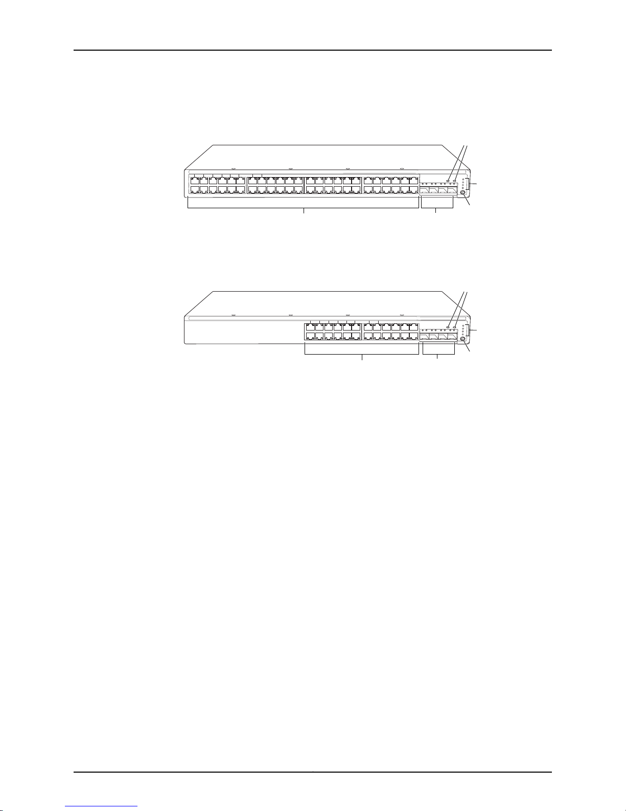
Figure 1 on page 6 shows the front panel of an EX2200 switch with 48 Gigabit Ethernet
ports. Figure 2 on page 6 shows the front panel of an EX2200 switch with 24 Gigabit
Ethernet ports.
5Copyright © 2011, Juniper Networks, Inc.
Page 26
01234567891011121314151617181920212223242526272829303132333435363738394041424344
45
0 1 2
SYS
ALM
SPD
DX
EN
POE
3
46
47
Network
ports
Port status mode LEDs
Mode
button
SFP
uplink
ports
Chassis
status
LEDs
g027000
012345678910111213141516171819202122
23
0 1 2
SYS
ALM
SPD
DX
EN
POE
3
Network
ports
Chassis
status
LEDs
g027002
SFP
uplink
ports
Port status mode LEDs
Mode
button
Complete Hardware Guide for EX2200 Ethernet Switches
Figure 1: Front Panel of an EX2200 Switch with 48 Gigabit Ethernet Ports
Figure 2: Front Panel of an EX2200 Switchwith 24 Gigabit Ethernet Ports
The front panel of an EX2200-C switch consists of the following components:
•
Network ports—depending on the switch model, either of:
•
12 10/100/1000BASE-T Ethernet ports, (non-PoE) in EX2200-C-12T
•
12 10/100/1000BASE-T Ethernet ports, (PoE+) in EX2200-C-12P
•
2 built-in dual-purpose uplink ports, each of which includes one 10/100/1000 RJ-45
Ethernet port and one SFP port
•
1 USB port
•
1 Mini-USB console port
•
1 RJ-45 console port
•
1 Management Ethernet port
•
2 chassis status LEDs
•
4 port status mode LEDs in PoE+ and 3 port status mode LEDs in non-PoE
•
Mode button
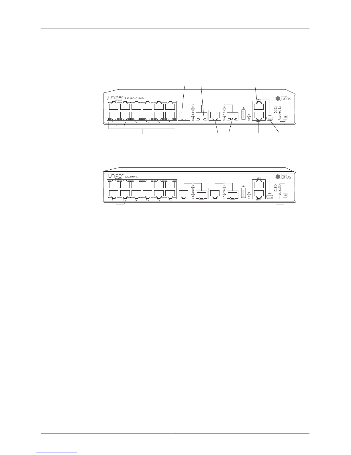
Figure 3 on page 7 shows the front panel of an EX2200-C Switchwith 12 Gigabit Ethernet
PoE+ ports and Figure 4 on page 7 shows the front panel of an EX2200-C Switch with
12 Gigabit Ethernet non-PoE ports.
Copyright © 2011, Juniper Networks, Inc.6
Page 27
g021150
Network por ts
Dual-purpose
uplink por ts 0
Dual-purpose
uplink por ts 1
Console
port
USB
port
Mini USB
port
Management
port
g021151
Chapter 1: EX2200 Switch Overview
Figure 3: Front Panel of an EX2200-C Switch with 12 Gigabit Ethernet
Ports (PoE+)
Figure 4: Front Panel of an EX2200-C Switch with 12 Gigabit Ethernet
Ports (non-PoE)
Rear Panel of an EX2200 Switch
The rear panel of the EX2200 switch except the EX2200-C switch models consists of
the following components:
•
Management Ethernet port
•
USB port
•
Console port
•
Protective earthing terminal
•
ESD point
•
Air exhaust
•
Serial number ID label
•
AC power cord inlet or DC power terminals
Figure 5 on page 8 shows the rear panel of an EX2200 switch with an AC power supply.
All EX2200 switches except the EX2200-C switch model have three exhaust openings
on the rear panel. The two exhaust openings on the left have fans behind them and are
open. The exhaust opening on the right is open on Power over Ethernet (PoE) models
and closed on non-PoE models. On PoE models, this opening exhausts the air from the
fan at the air intake for the power supply on the side panel.
The power cord retainer clips extend out of the chassis by 3 in.
7Copyright © 2011, Juniper Networks, Inc.
Page 28

g027001
USB
port
Management
Ethernet port
Console
port
Protective
earthing terminal
Air exhaust without fan
(closed on non-PoE models)
Air exhaust
with fan
AC power
cord inlet
ESD
point
EX2200-24-4G REV: X1
750-026464 REV: X3
MAC:00:23:9C:oE:19:00
Mfg.Date
20090227
MADEIN CHINA
Serial number
ID label
Air intake with fan for power supply
(fan on PoE models only)
g021152
Heatsink
Complete Hardware Guide for EX2200 Ethernet Switches
Figure 5: Rear Panel of an EX2200 Switch With an AC Power Supply
The rear panel of an EX2200-C switch consists of the following components:
•
Protective earthing terminal
•
ESD point
•
Serial number ID label
•
AC power cord inlet
•
Heatsink-only in PoE+ models
Figure 6 on page 8 shows the rear panel of an EX2200-C-12P switch with heatsink.
EX2200-C switches being fanless models have no exhaust openings. The switch has
vents on the top and on both the sides of the chassis. The PoE+ models have heatsink
installed in the rear panel to dissipate the heat, while non-PoE models have no heatsink.
Figure 6: Rear Panel of an EX2200-C-12P Switch with Heatsink
Related
Documentation
EX2200 Switch Models on page 8•
• Site Preparation Checklist for EX2200 Switches on page 51
EX2200 Switch Models
The EX2200 switch is available with 12, 24, or 48 built-in network ports with full Power
over Ethernet (PoE) capability (all 12, 24, or 48 built-in network ports support PoE) or no
PoE capability. EX2200 switches with DC power supply do not provide PoE. Table 1 on
page 9 lists the EX2200 switch models.
Copyright © 2011, Juniper Networks, Inc.8
Page 29

Table 1: EX2200 Switch Models
Chapter 1: EX2200 Switch Overview
Ports in Which PoE Is
AvailableAccess PortsModel
Related
EX2200 Switches Hardware Overview on page 3•
Documentation
Chassis Physical Specifications for EX2200 Switches
The EX2200 switch chassis is a rigid sheet-metal structure that houses the hardware
components. Table 2 on page 9 summarizes the physical specifications of the EX2200
switch chassis.
Maximum PoE
Power Available
First Junos OS
Release
11.3R1––12 Gigabit EthernetEX2200-C-12T-2G
11.3R1100 WAll 12 ports12 Gigabit EthernetEX2200-C-12P-2G
10.1R1––24 Gigabit EthernetEX2200-24T-4G
10.1R1405 WAll 24 ports24 Gigabit EthernetEX2200-24P-4G
11.3R1––24 Gigabit EthernetEX2200-24T-4G-DC
10.1R1––48 Gigabit EthernetEX2200-48T-4G
10.1R1405 WAll 48 ports48 Gigabit EthernetEX2200-48P-4G
Table 2: Physical Specifications of the EX2200 Switch Chassis
EX2200-C ValueEX2200 ValueDescription
1.75 in. (4.4 cm)1.75 in. (4.45 cm)Chassis height
Chassis width
Weight
Documentation
Related
•
17.5 in. (44.5 cm)
•
19 in. (48.2 cm) with mounting brackets
attached
10.5 in. (26.7 cm)Chassis depth
•
EX2200-24T: 6 lb (2.7 kg)
•
EX2200-24P: 8 lb (3.6 kg)
•
EX2200-24T-DC: 6 lb (2.7 kg)
•
EX2200-48T: 8 lb (3.6 kg)
•
EX2200-48P: 10 lb (4.5 kg)
Rack Requirements for EX2200 Switches on page 57•
• Cabinet Requirements for EX2200 Switches on page 58
•
10.6 in. (26.92 cm)
•
19 in. (48.26 cm) with mounting brackets
•
EX2200-C-12T: 9.0 in. (22.8 cm)
•
EX2200-C-12P: 9.4 in. (23.8 cm)
•
EX2200-C-12T: 4.6 lb (2.1 kg)
•
EX2200-C-12P: 6.4 lb (2.9 kg)
9Copyright © 2011, Juniper Networks, Inc.
Page 30

Complete Hardware Guide for EX2200 Ethernet Switches
• Mounting an EX2200 Switch on page 74
• Installing and Connecting an EX2200 Switch on page 71
EX2200 Switch Hardware and CLI Terminology Mapping
This topic describes the hardware terms used in EX2200 switch documentation and the
corresponding terms used in the Junos OS command line interface (CLI). See Table 3 on
page 10.
Table 3: CLI Equivalents of Terms Used in Documentation for EX2200 Switches
Hardware Item (as
displayed in the CLI)
Chassis
FPC (n)
Description (as
displayed in the CLI)
•
EX2200-C-12T-2G
•
EX2200-C-12P-2G
•
EX2200-24T-4G
•
EX2200-24P-4G
•
EX2200-24T-4G-DC
•
EX2200-48T-4G
•
EX2200-48P-4G
the Flexible PIC
Concentrator (FPC)
One of the following:
•
EX2200-C-12T-2G
•
EX2200-C-12P-2G
•
EX2200-24T-4G
•
EX2200-24P-4G
•
EX2200-24T-4G-DC
•
EX2200-48T-4G
•
EX2200-48P-4G
Value (as displayed
in the CLI)
Value of n is always 0.Abbreviated name of
Item in
Documentation
Switch chassis–One of the following:
The switch does not
have actual FPCs. In
this case, FPC refers to
the switch itself.
Additional
Information
“Chassis Physical
Specifications for
EX2200 Switches” on
page 9
Understanding
Interface Naming
Conventions on EX
Series Switches
PIC (n)
Abbreviated name of
the Physical Interface
Card (PIC)
n is a value in the range
of 0-1.
The switch does not
have actual PIC
devices; see entries for
PIC 0 through PIC 1 for
the equivalent item on
the switch.
Copyright © 2011, Juniper Networks, Inc.10
Understanding
Interface Naming
Conventions on EX
Series Switches
Page 31

Chapter 1: EX2200 Switch Overview
Table 3: CLI Equivalents of Terms Used in Documentation for EX2200 Switches (continued)
Hardware Item (as
displayed in the CLI)
Xcvr (n)
Description (as
displayed in the CLI)
•
12x 10/100/1000
BASE-T
•
24x 10/100/1000
BASE-T
•
48x 10/100/1000
BASE-T
•
2x (10/100/1000
BASE-T or GE SFP)
or
•
2x (100/1000
BASE-X)
•
4x GE SFP
Abbreviated name of
the transceiver
Value (as displayed
in the CLI)
PIC 0One of the following:
PIC 1One of the following:
to the number of the
port in which the
transceiver is installed.
Item in
Documentation
Built-in network ports
on the front panel of
the switch
Built-in uplink ports
and dual-purpose
uplink ports on the
front panel of the
switch
Optical transceiversn is a value equivalent
AC power supplyValue of n is always 0.Built-in power supplyPower supply (n)
Additional
Information
“EX2200 Switches
Hardware Overview”
on page 3
“EX2200 Switches
Hardware Overview”
on page 3
“Optical Interface
Support in EX2200
Switches” on page 25
“Power Supply in
EX2200 Switches” on
page 18
Fan
Documentation
Related
Fan–Fan
NOTE: EX2200-C
switches are fanless
models.
• EX Series Switches Hardware and CLI Terminology Mapping
• EX2200 Switches Hardware Overview on page 3
“Cooling System and
Airflow in an EX2200
Switch” on page 19
11Copyright © 2011, Juniper Networks, Inc.
Page 32

Complete Hardware Guide for EX2200 Ethernet Switches
Copyright © 2011, Juniper Networks, Inc.12
Page 33

CHAPTER 2
g027003
0 1 2
SYS
ALM
SPD
DX
EN
POE
3
Chassis
status LEDs
g021153
Chassis
status LEDs
Component Descriptions
•
Chassis Status LEDs in EX2200 Switches on page 13
•
Network Port and Uplink Port LEDs in EX2200 Switches on page 14
•
Management Port LEDs in EX2200 Switches on page 17
•
Power Supply in EX2200 Switches on page 18
•
Cooling System and Airflow in an EX2200 Switch on page 19
Chassis Status LEDs in EX2200 Switches
The front panel of an EX2200 switch has two chassis status LEDs labeled SYS and ALM
on the far right side of the panel. See Figure 7 on page 13 and Figure 8 on page 13.
Figure 7: Chassis Status LEDs in an EX2200 Switch Except the EX2200-C
Switch
Figure 8: Chassis Status LEDs in an EX2200-C Switch
Table 4 on page 14 describes the chassis status LEDs in an EX2200 switch, their colors
and states, and the status they indicate.
13Copyright © 2011, Juniper Networks, Inc.
Page 34

g041128
Link/
Activity
Status
Complete Hardware Guide for EX2200 Ethernet Switches
Table 4: Chassis Status LEDs in an EX2200 Switch
State and DescriptionColorLED Label
GreenSYS
A major alarm (red) indicates a critical error condition that requires immediate action.
A minor alarm (amber) indicates a noncritical condition that requires monitoring or
maintenance. A minor alarm that is left unchecked might cause interruption in service or
performance degradation.
•
•
•
There is no alarm.UnlitALM
There is a minor alarm.Amber
There is a major alarm.Red
On steadily—The switch is functioning normally.
Blinking—The switch is booting.
Off—The switch is off.
Both LEDs can be lit simultaneously.
You can view the colors of the two LEDs remotely through the CLI by issuing the
operational mode command show chassis led.
Related
Documentation
EX2200 Switches Hardware Overview on page 3•
• Checking Active Alarms with the J-Web Interface
• Understanding Alarm Types and Severity Levels on EX Series Switches
Network Port and Uplink Port LEDs in EX2200 Switches
Each network port and uplink port on the front panel of an EX2200 switch has two LEDs
that indicate link/activity and port status. Each dual-purpose uplink port in an EX2200-C
switch has two pairs of LEDs that indicate the link/activity status, one pair for each of
the two ports that constitute the dual-purpose uplink port. See Figure 9 on page 14,
Figure 10 on page 15, and Figure 11 on page 15.
Figure 9: LEDs on the Network Port
Copyright © 2011, Juniper Networks, Inc.14
Page 35
g027007
0 1 2
SYS
ALM
SPD
DX
EN
POE
3
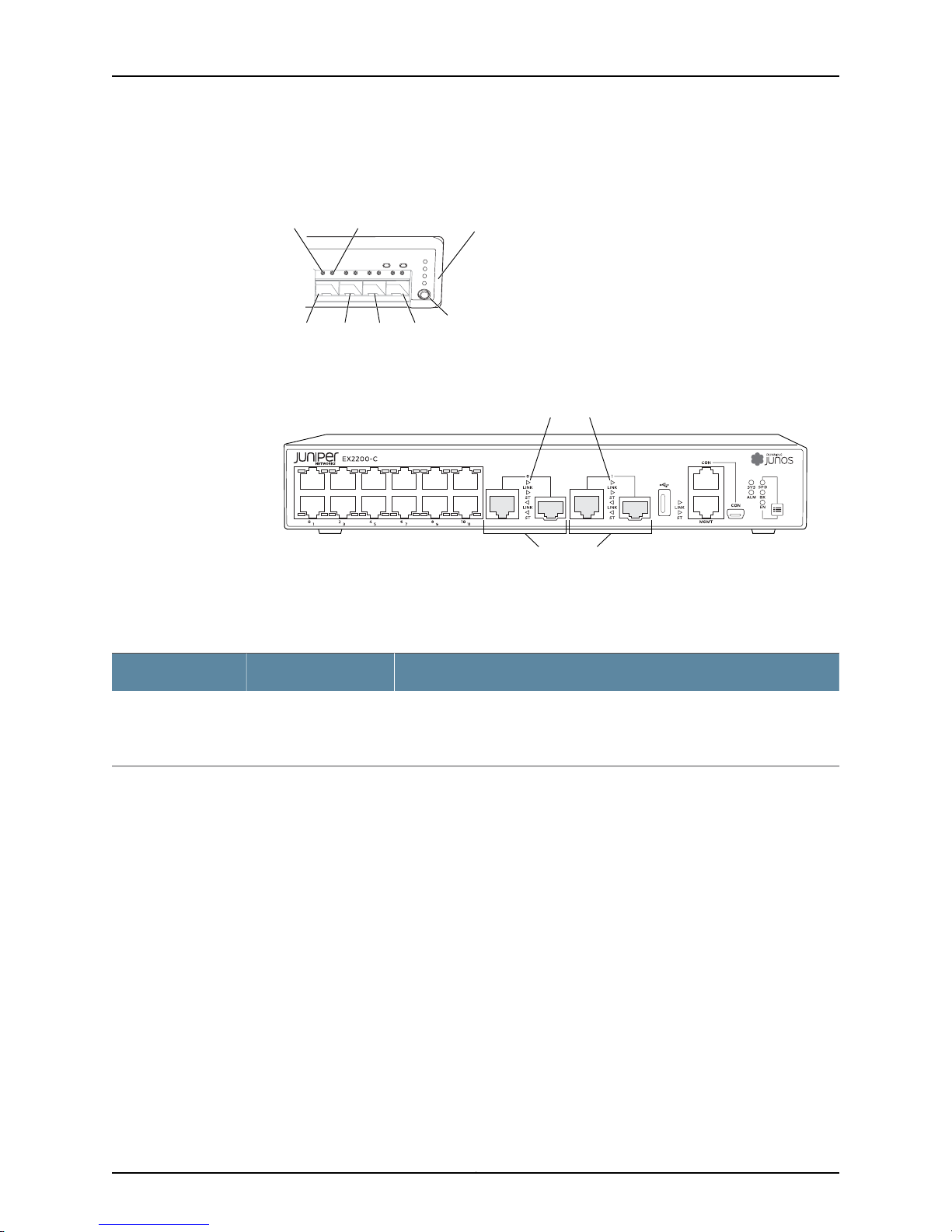
Port 1 Port 2 Port 3
Mode
button
Link/Activity
LED
Status
LED
Port 0
Port status
mode LEDs
g021154
Dual-purpose
uplink por ts
Port status mode LEDs
Chapter 2: Component Descriptions
Figure 10: LEDs on the Uplink Ports and Port Status Mode LEDs in an
EX2200 Switch Except the EX2200-C Switch Model
Figure 11: Port status mode LEDs of the Dual-purpose uplink Ports of an
EX2200-C Switch
Table 5 on page 15 describes the Link/Activity LED.
Table 5: Link/Activity LED on the Network Ports and Uplink Ports in EX2200 Switches
State and DescriptionColorLED
•
GreenLink/Activity
In Figure 9 on page 14, Figure 10 on page 15, and Figure 11 on page 15 show the LEDs that
indicatethe statusof one of the four port parameters—speed,duplexmode, administrative
status, and Power over Ethernet (PoE) status. Use the mode button below the POE LED
on the far right side of the front panel to toggle the Status LED to show the different port
parameters. You can tell which port parameter is indicated by the Status LED by seeing
which port status mode LED (SPD, DX, EN, and POE) is lit. (See Figure 10 on page 15).
Table 6 on page 16 describes the Status LED.
Blinking—The port and the link are active, and there is link activity.
•
On steadily—The port and the link are active, but there is no link activity.
•
Off—The port is not active.
15Copyright © 2011, Juniper Networks, Inc.
Page 36

Complete Hardware Guide for EX2200 Ethernet Switches
Table 6: Status LED on the Network Ports, Uplink Ports, and Dual-Purpose Uplink Ports in
EX2200 Switches
State and DescriptionPort Parameters
Speed
Duplex mode
Administrative status
PoE status
Indicates the speed. The speed indicators for network ports are:
•
One blink per second—10 Mbps
•
Two blinks per second—100 Mbps
•
Three blinks per second—1000 Mbps
The speed indicators for uplink ports are:
•
On steadily—1000 Mbps
•
Off—10/100 Mbps
The speed indicators for dual-purpose uplink ports of EX2200-C switch model are:
•
One blink per second—10 Mbps
•
Two blinks per second—100 Mbps
•
Three blinks per second—1000 Mbps
Indicates the duplex mode. The status indicators are:
•
On steadily—Port is set to full-duplex mode.
•
Off—Port is set to half-duplex mode.
Indicates the administrative status. The status indicators are:
•
On steadily—Port is administratively enabled.
•
Off—Port is administratively disabled.
Indicates the PoE status. The status indicators for network ports are:
•
On steadily—PoE is availableon the port, a device that draws power from the port
is connected to the port, and the device is drawing power from the port.
•
Blinking—PoEis availableon the port, but no power is drawn from the port because
of one of the following:
•
No device that draws power from the port is connected to the port.
•
A device that draws power from the port is connectedto the port, but the device
is not drawing any power from the port.
•
Off—PoE is not available on the port.
NOTE: PoE Status LED is available on the following EX2200 switch models:
•
EX2200-C-12P-2G
•
EX2200-24P-4G
•
EX2200-48P-4G
PoE is not available on uplink ports; therefore,the LED for those ports is always unlit.
You can tell which port parameter is indicated by the Status LED on network ports, uplink
ports, and dual-purpose uplink ports by issuing the operational mode command show
chassis led.
Copyright © 2011, Juniper Networks, Inc.16
Page 37

g027006
Link/Activity
LED
Status
LED
g021155
Status
LED
Link/Activity
LED
Chapter 2: Component Descriptions
Related
Documentation
EX2200 Switches Hardware Overview on page 3•
• Configuring Gigabit Ethernet Interfaces (CLI Procedure)
• Configuring Gigabit Ethernet Interfaces (J-Web Procedure)
Management Port LEDs in EX2200 Switches
The management port on an EX2200 switch has two LEDs that indicate link/activity and
port status. The EX2200 switches except the EX2200-C switch models have the
management port on the rear panel and the EX2200-C switch has the management port
on the front panel. See Figure 12 on page 17 and Figure 13 on page 17.
Figure 12: LEDs on the Management Port on an EX2200 Switch Except
the EX2200-C Switch Model
Figure 13: LEDs on the Management Port on an EX2200-C Switch
Table 7 on page 17 describes the Link/Activity LED.
Table 7: Link/Activity LED on the Management Port on EX2200 Switches
State and DescriptionColorLED
•
Blinking—The port and the link are active, and there is link
activity.
•
On steadily—The port and the link are active, but there is no
link activity.
•
Off—The port is not active.
GreenLink/Activity
Table 8 on page 18 describes the Status LED.
17Copyright © 2011, Juniper Networks, Inc.
Page 38

Complete Hardware Guide for EX2200 Ethernet Switches
Table 8: Status LED on the Management Port on EX2200 Switches
State and DescriptionColorLED
GreenStatus
Related
Connectingan EX Series Switch to a Network for Out-of-Band Management on page113•
Documentation
Power Supply in EX2200 Switches
The power supply in EX2200 switches is built in along the rear panel of the chassis, with
an AC power cord inlet or DC power terminals on the rear panel to connect power to the
switch.
Table 9 on page 18 lists the power consumed by each EX2200 switch model. The
maximum power available on a PoE port is 30 W for switches running Junos OS Release
10.3 or later and 15.4 W for switches running Junos OS Release 10.2 or earlier.
Table 9: Power Consumed by EX2200 Switches
Number of PoE-Enabled
PortsModel Number
Indicates the speed. The speed indicators are:
•
One blink per second—10 Mbps
•
Two blinks per second—100 Mbps
Maximum Power
Consumed by the Switch
Maximum PoE Power
Available
–30 W–EX2200-C-12T
Related
Documentation
12EX2200-C-12P
drawn)
24EX2200-24P
drawn)
48EX2200-48P
drawn)
AC Power Cord Specifications for EX2200 Switches on page 66•
• EX2200 Switches Hardware Overview on page 3
• Power Specifications for EX2200 Switches on page 65
• Connecting AC Power to an EX2200 Switch on page 109
• Connecting DC Power to an EX2200 Switch on page 110
100 W30 W (when no PoE power is
–50 W–EX2200-24T
405 W60 W (when no PoE power is
–50 W–EX2200-24T-DC
–76 W–EX2200-48T
405 W91 W (when no PoE power is
Copyright © 2011, Juniper Networks, Inc.18
Page 39

• Connecting Earth Ground to an EX Series Switch on page 103
g027021
Chassis rear
Chassis front
Fans
Cooling System and Airflow in an EX2200 Switch
Thecooling systemin EX2200 switches, exceptEX2200-C, the compact, fanlessmodels,
consists of two fans along the rear of the chassis that provide side-to-rearchassis cooling.
In the PoE models of these switches, there is an additional fan in the power supply.
In the EX2200-C switch the cooling is done by the vents on top and sides of the chassis
in non-PoE models and by heatsinks in PoE+ models. Do not block the vents on the
chassis. Doing this can lead to overheating of the switch chassis.
Figure 14 on page 19 shows the airflow in non-PoE models of EX2200 switches, except
for the EX2200-C models.
Figure 14: Airflow Through Non-PoE Models of EX2200 Switches Except
the EX2200-C Switch Model
Chapter 2: Component Descriptions
Figure 15 on page 20 shows the airflow in PoE models of EX2200 switches, except
EX2200-C models.
19Copyright © 2011, Juniper Networks, Inc.
Page 40

g027008
Chassis rear
Chassis front
Fans Fan
Complete Hardware Guide for EX2200 Ethernet Switches
Figure 15: Airflow Through PoE Models of EX2200 Switches Except the
EX2200-C Switch Models
Related
Documentation
Under normal operating conditions, the fans operate at a moderate speed to reduce
noise. Temperature sensors in the chassis monitor the temperature within the chassis.
If any fan fails or if the temperature inside the chassis rises above the threshold, the
switch raises an alarm and all functioning fans operate at a higher speed than normal.
If the temperature inside the chassis rises above the threshold, the switch shuts down
automatically.
• EX2200 Switches Hardware Overview on page 3
• Chassis Status LEDs in EX2200 Switches on page 13
• Understanding Alarm Types and Severity Levels on EX Series Switches
• Prevention of Electrostatic Discharge Damage on page 180
Copyright © 2011, Juniper Networks, Inc.20
Page 41

CHAPTER 3
Component Specifications
•
USB Port Specifications for an EX Series Switch on page 21
•
Mini-USB Port Specifications for an EX2200 Switch on page 22
•
Network Port Connector Pinout Information for an EX2200 Switch on page 23
•
Console Port Connector Pinout Information for an EX Series Switch on page 23
•
Management Port Connector Pinout Information for an EX2200 Switch on page 24
•
Optical Interface Support in EX2200 Switches on page 25
USB Port Specifications for an EX Series Switch
The following Juniper Networks USB flash drives have been tested and are officially
supported for the USB port on all EX Series switches:
•
RE-USB-1G-S
•
RE-USB-2G-S
•
RE-USB-4G-S
CAUTION: Any USB memory product not listed as supported for EX Series
switches has not been tested by Juniper Networks. The use of any
unsupported USB memory product could expose your EX Series switch to
unpredictablebehavior.Juniper Networks TechnicalAssistanceCenter (JTAC)
can provide only limited support for issues related to unsupported hardware.
We strongly recommend that you use only supported USB flash drives.
All USB flash drives used on EX Series switches must have the following features:
•
USB 2.0 or later.
•
Formatted with a FAT or MS-DOS file system.
•
If the switch is running Junos OS Release 9.5 or earlier, the formatting method must
use a master boot record. Microsoft Windows formatting, by default, does not use a
master boot record. See the documentation for your USB flash drive for information
on how your USB flash drive is formatted.
21Copyright © 2011, Juniper Networks, Inc.
Page 42

Complete Hardware Guide for EX2200 Ethernet Switches
Related
Documentation
See EX2200 Switches Hardware Overview on page 3 for port location.•
• See Rear Panel of an EX3200 Switch for port location.
• See Rear Panel of an EX3300 Switch for port location.
• See Rear Panel of an EX4200 Switch for port location.
• See Front Panel of an EX4500 Switch for port location.
• See Switch Fabric and Routing Engine (SRE) Module in an EX6200 Switch for port
location.
• See Switch Fabric and Routing Engine (SRE) Module in an EX8208 Switch for port
location.
• See Routing Engine (RE) Module in an EX8216 Switch for port location.
• Booting an EX Series Switch Using a Software Package Stored on a USB Flash Drive
Mini-USB Port Specifications for an EX2200 Switch
The EX2200-C switch, the compact, fanless model, has two management console ports:
an RJ-45 port, and a Mini-USB Type-B port.
By default, the RJ-45 port is set as the active console port. It can display all the early boot
and low-level message output and you can access the switch through this port in the
debugger prompt. The Mini-USB Type-B port is the passive console port. Youcan change
the status of the port to active or passive using the port-type configuration statement.
See Configuring the Console Port Type (CLI Procedure).).
The Mini-USB Type-B console port uses a Mini-B plug (5-pin) connector to connect to
a console management device. The default baud rate for the console port is 9600 baud.
Table 10 on page 22 provides the pinout information of the Mini-USB Type-B console
port.
Table 10: Mini-USB Type-B Console Port Pinout Information for EX2200-C Switches
DescriptionSignalPin
+5 VDCVCC1
Data -D-2
Data +D+3
May be N/C, GND or used as an attached device presence indicatorN/CX
GroundGND4
Related
Documentation
See EX2200 Switches Hardware Overview on page 3 for port location.•
• Configuring the Console Port Type (CLI Procedure)
Copyright © 2011, Juniper Networks, Inc.22
Page 43

Chapter 3: Component Specifications
Network Port Connector Pinout Information for an EX2200 Switch
A network port on an EX2200 switch uses an RJ-45 connector to connect to a device.
The port uses an autosensing RJ-45 connector to support a 10/100/1000Base-T
connection. Two LEDs on the port indicate link/activity on the port and the port status.
See “Network Port and Uplink Port LEDs in EX2200 Switches” on page 14.
Table 11 on page 23 provides the pinout information for the RJ-45 connector. An RJ-45
cable, with a connector attached, is supplied with the switch.
Table 11: Network Port Connector Pinout Information for EX2200 Switches
DescriptionSignalPin
Related
Documentation
TRP1+1
TRP1-2
TRP2+3
TRP2-6
Transmit/receive data pair 1
Negative Vport (in PoE models)
Transmit/receive data pair 1
Negative Vport (in PoE models)
Transmit/receive data pair 2
Positive Vport (in PoE models)
Transmit/receive data pair 3TRP3+4
Transmit/receive data pair 3TRP3-5
Transmit/receive data pair 2
Positive Vport (in PoE models)
Transmit/receive data pair 4TRP4+7
Transmit/receive data pair 4TRP4-8
EX2200 Switches Hardware Overview on page 3•
Console Port Connector Pinout Information for an EX Series Switch
The console port on an EX Series switch is an RS-232 serial interface that uses an RJ-45
connector to connect to a console management device. The default baud rate for the
console port is 9600 baud.
Table 12 on page 24 provides the pinout information for the RJ-45 console connector. An
RJ-45 cable and an RJ-45 to DB-9 serial port adapter are supplied with the switch.
23Copyright © 2011, Juniper Networks, Inc.
Page 44

Complete Hardware Guide for EX2200 Ethernet Switches
NOTE: If your laptop or PC does not have a DB-9 male connector pin and you
want to connect your laptop or PC directly to an EX Series switch, use a
combination of the RJ-45 to DB-9 female adapter supplied with the switch
and a USB to DB-9 male adapter. You must provide the USB to DB-9 male
adapter.
Table 12: EX Series Switches Console Port Connector Pinout Information
DescriptionSignalPin
Request to sendRTS Output1
Data terminal readyDTR Output2
Transmit dataTxD Output3
Signal groundSignal Ground4
Related
Documentation
Signal groundSignal Ground5
Receive dataRxD Input6
Data carrier detectCD Input7
Clear to sendCTS Input8
See EX2200 Switches Hardware Overview on page 3 for port location.•
• See Rear Panel of an EX3200 Switch for port location.
• See Rear Panel of an EX3300 Switch for port location.
• See Rear Panel of an EX4200 Switch for port location.
• See Front Panel of an EX4500 Switch for port location.
• See Switch Fabric and Routing Engine (SRE) Module in an EX6200 Switch for port
location.
• See Switch Fabric and Routing Engine (SRE) Module in an EX8208 Switch for port
location.
• See Routing Engine (RE) Module in an EX8216 Switch for port location.
• Connecting an EX Series Switch to a Management Console on page 115
• Configuring the Console Port Type (CLI Procedure)
Management Port Connector Pinout Information for an EX2200 Switch
The management port on an EX2200 switch uses an RJ-45 connector to connect to a
management device for out-of-band management.
Copyright © 2011, Juniper Networks, Inc.24
Page 45

Chapter 3: Component Specifications
The port uses an autosensing RJ-45 connector to support a 10/100Base-T connection.
Two LEDs on the port indicate link/activity on the port and the administrative status of
the port. See “Management Port LEDs in EX2200 Switches” on page 17.
Table 13 on page 25 provides the pinout information for the RJ-45 connector for the
managementport. An RJ-45 cable,with a connectorattached,is supplied with the switch.
Table 13: Management Port Connector Pinout Information for EX2200 Switches
DescriptionSignalPin
Transmit/receive data pair 1TRP1+1
Transmit/receive data pair 1TRP1-2
Transmit/receive data pair 2TRP2+3
Transmit/receive data pair 2TRP2-6
Related
Documentation
See EX2200 Switches Hardware Overview on page 3 for port location.•
• Connecting an EX Series Switchto a Network for Out-of-Band Management on page 113
Optical Interface Support in EX2200 Switches
Uplink ports and dual-purpose uplink ports on the front panel in EX2200 switches support
SFP transceivers. This topic describes the optical interfaces supported for those
transceivers. It also lists the copper interface supported for the SFP transceivers.
NOTE: Use only optical transceivers and optical connectors purchased from
Juniper Networks for your EX Series switches.
The two tables in this topic describe the optical interface support over single-mode
fiber-optic (SMF) and multimode fiber-optic (MMF) cables and over the copper interface
for SFP transceivers:
•
Table14 on page 26—Optical interface support and copper interfacesupport for Gigabit
Ethernet SFP transceivers in EX2200 switches except EX2200-C switches.
•
Table 15 on page 37—Optical interface support for Fast Ethernet SFP transceivers
except EX2200-C switches.
•
Table 16 on page 43—Optical interface support and copper interface support for SFP
Transceivers in EX2200-C switches.
25Copyright © 2011, Juniper Networks, Inc.
Page 46

Complete Hardware Guide for EX2200 Ethernet Switches
Table 14: Optical Interface Support and Copper Interface Support for Gigabit Ethernet SFP
Transceivers in EX2200 Switches except EX2200-C Switches
ValueSpecificationEthernet Standard
EX-SFP-1GE-TModel Number1000BASE-T
10/100/1000 MbpsRate
RJ-45Connector Type
–Transmitter Wavelength
–Minimum Launch Power
–Maximum Launch Power
–Minimum Receiver Sensitivity
–Maximum Input Power
–Core/Cladding Size
–Modal Bandwidth
100 m (328 ft)Distance
Junos OS for EX Series switches, Release 10.1 or laterSoftware Required
Copyright © 2011, Juniper Networks, Inc.26
Page 47

Chapter 3: Component Specifications
Table 14: Optical Interface Support and Copper Interface Support for Gigabit Ethernet SFP
Transceivers in EX2200 Switches except EX2200-C Switches (continued)
ValueSpecificationEthernet Standard
EX-SFP-1GE-SXModel Number1000BASE-SX
1000 MbpsRate
LCConnector Type
DualFiber Count
850 nmTransmitter Wavelength
–9.5 dBmMinimum Launch Power
–3 dBmMaximum Launch Power
Distance
–21 dBmMinimum Receiver Sensitivity
0 dBmMaximum Input Power
MMFFiber Type
220 m
(722 ft)
Junos OS for EX Series switches, Release 10.1 or laterSoftware Required
275 m
(902 ft)
500 m
(1640 ft)
50/125 µm50/125 µm62.5/125 µm62.5/125 µmCore/Cladding Size
OM2–OM1FDDIFiber Grade
500 MHz/km400 MHz/km200 MHz/km160 MHz/kmModal Bandwidth
550 m
(1804 ft)
27Copyright © 2011, Juniper Networks, Inc.
Page 48

Complete Hardware Guide for EX2200 Ethernet Switches
Table 14: Optical Interface Support and Copper Interface Support for Gigabit Ethernet SFP
Transceivers in EX2200 Switches except EX2200-C Switches (continued)
ValueSpecificationEthernet Standard
EX-SFP-1GE-LXModel Number1000BASE-LX
1000 MbpsRate
LCConnector Type
DualFiber Count
1310 nmTransmitter Wavelength
–9.5 dBmMinimum Launch Power
–3 dBmMaximum Launch Power
–25 dBmMinimum Receiver Sensitivity
–3 dBmMaximum Input Power
SMFFiber Type
9/125 µmCore/Cladding Size
–Modal Bandwidth
10 km (6.2 miles)Distance
Junos OS for EX Series switches, Release 10.1 or laterSoftware Required
Copyright © 2011, Juniper Networks, Inc.28
Page 49

Chapter 3: Component Specifications
Table 14: Optical Interface Support and Copper Interface Support for Gigabit Ethernet SFP
Transceivers in EX2200 Switches except EX2200-C Switches (continued)
ValueSpecificationEthernet Standard
EX-SFP-GE10KT13R14Model Number1000BASE-BX-U
1000 MbpsRate
LCConnector Type
SingleFiber Count
1310 nmTransmitter Wavelength
1490 nmReceiver Wavelength
–9 dBmMinimum Launch Power
–3 dBmMaximum Launch Power
–30 dBmMinimum Receiver Sensitivity
–3 dBmMaximum Input Power
SMFFiber Type
9/125 µmCore/Cladding Size
–Modal Bandwidth
10 km (6.2 miles)Distance
Junos OS for EX Series switches, Release 11.2 or laterSoftware Required
29Copyright © 2011, Juniper Networks, Inc.
Page 50

Complete Hardware Guide for EX2200 Ethernet Switches
Table 14: Optical Interface Support and Copper Interface Support for Gigabit Ethernet SFP
Transceivers in EX2200 Switches except EX2200-C Switches (continued)
ValueSpecificationEthernet Standard
EX-SFP-GE10KT14R13Model Number1000BASE-BX-D
1000 MbpsRate
LCConnector Type
SingleFiber Count
1490 nmTransmitter Wavelength
1310 nmReceiver Wavelength
–9 dBmMinimum Launch Power
–3 dBmMaximum Launch Power
–30 dBmMinimum Receiver Sensitivity
–3 dBmMaximum Input Power
SMFFiber Type
9/125 µmCore/Cladding Size
–Modal Bandwidth
10 km (6.2 miles)Distance
Junos OS for EX Series switches, Release 11.2 or laterSoftware Required
Copyright © 2011, Juniper Networks, Inc.30
Page 51

Chapter 3: Component Specifications
Table 14: Optical Interface Support and Copper Interface Support for Gigabit Ethernet SFP
Transceivers in EX2200 Switches except EX2200-C Switches (continued)
ValueSpecificationEthernet Standard
EX-SFP-GE10KT13R15Model Number1000BASE-BX-U
1000 MbpsRate
LCConnector Type
SingleFiber Count
1310 nmTransmitter Wavelength
1550 nmReceiver Wavelength
–9 dBmMinimum Launch Power
–3 dBmMaximum Launch Power
–3 dBmMinimum Receiver Sensitivity
–21 dBmMaximum Input Power
SMFFiber Type
9/125 µmCore/Cladding Size
–Modal Bandwidth
10 km (6.2 miles)Distance
Junos OS for EX Series switches, Release 11.2 or laterSoftware Required
31Copyright © 2011, Juniper Networks, Inc.
Page 52

Complete Hardware Guide for EX2200 Ethernet Switches
Table 14: Optical Interface Support and Copper Interface Support for Gigabit Ethernet SFP
Transceivers in EX2200 Switches except EX2200-C Switches (continued)
ValueSpecificationEthernet Standard
EX-SFP-GE10KT15R13Model Number1000BASE-BX-D
1000 MbpsRate
LCConnector Type
SingleFiber Count
1550 nmTransmitter Wavelength
1310 nmReceiver Wavelength
–9 dBmMinimum Launch Power
–3 dBmMaximum Launch Power
–3 dBmMinimum Receiver Sensitivity
–21 dBmMaximum Input Power
SMFFiber Type
9/125 µmCore/Cladding Size
–Modal Bandwidth
10 km (6.2 miles)Distance
Junos OS for EX Series switches, Release 11.2 or laterSoftware Required
Copyright © 2011, Juniper Networks, Inc.32
Page 53

Chapter 3: Component Specifications
Table 14: Optical Interface Support and Copper Interface Support for Gigabit Ethernet SFP
Transceivers in EX2200 Switches except EX2200-C Switches (continued)
ValueSpecificationEthernet Standard
EX-SFP-GE40KT13R15Model Number1000BASE-BX-U
1000 MbpsRate
LCConnector Type
SingleFiber Count
1310 nmTransmitter Wavelength
1550 nmReceiver Wavelength
–6.5 dBmMinimum Launch Power
2 dBmMaximum Launch Power
–3 dBmMinimum Receiver Sensitivity
–23 dBmMaximum Input Power
SMFFiber Type
9/125 µmCore/Cladding Size
–Modal Bandwidth
40 km (24.8 miles)Distance
Junos OS for EX Series switches, Release 11.2 or laterSoftware Required
33Copyright © 2011, Juniper Networks, Inc.
Page 54

Complete Hardware Guide for EX2200 Ethernet Switches
Table 14: Optical Interface Support and Copper Interface Support for Gigabit Ethernet SFP
Transceivers in EX2200 Switches except EX2200-C Switches (continued)
ValueSpecificationEthernet Standard
EX-SFP-GE40KT15R13Model Number1000BASE-BX-D
1000 MbpsRate
LCConnector Type
SingleFiber Count
1550 nmTransmitter Wavelength
1310 nmReceiver Wavelength
–6.5 dBmMinimum Launch Power
2 dBmMaximum Launch Power
–3 dBmMinimum Receiver Sensitivity
–23 dBmMaximum Input Power
SMFFiber Type
9/125 µmCore/Cladding Size
–Modal Bandwidth
40 km (24.8 miles)Distance
Junos OS for EX Series switches, Release 11.2 or laterSoftware Required
Copyright © 2011, Juniper Networks, Inc.34
Page 55

Chapter 3: Component Specifications
Table 14: Optical Interface Support and Copper Interface Support for Gigabit Ethernet SFP
Transceivers in EX2200 Switches except EX2200-C Switches (continued)
ValueSpecificationEthernet Standard
EX-SFP-1GE-LX40KModel Number1000BASE-LX
1000 MbpsRate
LCConnector Type
DoubleFiber Count
1310 nmTransmitter Wavelength
–14 dBmMinimum Launch Power
–8 dBmMaximum Launch Power
–45 dBmMinimum Receiver Sensitivity
–3 dBmMaximum Input Power
SMFFiber Type
9/125 µmCore/Cladding Size
–Modal Bandwidth
40 km (24.8 miles)Distance
Junos OS for EX Series switches, Release 11.2 or laterSoftware Required
35Copyright © 2011, Juniper Networks, Inc.
Page 56

Complete Hardware Guide for EX2200 Ethernet Switches
Table 14: Optical Interface Support and Copper Interface Support for Gigabit Ethernet SFP
Transceivers in EX2200 Switches except EX2200-C Switches (continued)
ValueSpecificationEthernet Standard
EX-SFP-1GE-LHModel Number1000BASE-LH (or
1000BASE-ZX)
1000 MbpsRate
LCConnector Type
DualFiber Count
1550 nmTransmitter Wavelength
–2 dBmMinimum Launch Power
5 dBmMaximum Launch Power
–25 dBmMinimum Receiver Sensitivity
–3 dBmMaximum Input Power
SMFFiber Type
9/125 µmCore/Cladding Size
–Modal Bandwidth
70 km (43.5 miles)Distance
Junos OS for EX Series switches, Release 10.1 or laterSoftware Required
Copyright © 2011, Juniper Networks, Inc.36
Page 57

Chapter 3: Component Specifications
Table 15: Optical Interface Support for Fast Ethernet SFP Transceivers in EX2200 Switches
except EX2200-C Switches
ValueSpecificationEthernet Standard
EX-SFP-1FE-FXModel Number100BASE-FX
100 MbpsRate
LCConnector Type
DualFiber Count
1310 nmTransmitter Wavelength
–20 dBmMinimum Launch Power
–14 dBmMaximum Launch Power
–32.5 dBmMinimum Receiver Sensitivity
–8 dBmMaximum Input Power
MMFFiber Type
62.5/125 µmCore/Cladding Size
FDDI/OM1Fiber Grade
500 MHz/kmModal Bandwidth
2 km (1.2 miles)Distance
Junos OS for EX Series switches, Release 10.1 or laterSoftware Required
37Copyright © 2011, Juniper Networks, Inc.
Page 58

Complete Hardware Guide for EX2200 Ethernet Switches
Table 15: Optical Interface Support for Fast Ethernet SFP Transceivers in EX2200 Switches
except EX2200-C Switches (continued)
ValueSpecificationEthernet Standard
EX-SFP-1FE-LXModel Number100BASE-LX
100 MbpsRate
LCConnector Type
DualFiber Count
1310 nmTransmitter Wavelength
–15 dBmMinimum Launch Power
–8 dBmMaximum Launch Power
–31.5 dBmMinimum Receiver Sensitivity
–8 dBmMaximum Input Power
SMFFiber Type
9/125 µmCore/Cladding Size
–Modal Bandwidth
10 km (6.2 miles)Distance
Junos OS for EX Series switches, Release 11.2 or laterSoftware Required
Copyright © 2011, Juniper Networks, Inc.38
Page 59

Chapter 3: Component Specifications
Table 15: Optical Interface Support for Fast Ethernet SFP Transceivers in EX2200 Switches
except EX2200-C Switches (continued)
ValueSpecificationEthernet Standard
EX-SFP-FE20KT13R15Model Number100BASE-BX-U
100 MbpsRate
LCConnector Type
SingleFiber Count
1310 nmTransmitter Wavelength
1550 nmReceiver Wavelength
–14 dBmMinimum Launch Power
–8 dBmMaximum Launch Power
–45 dBmMinimum Receiver Sensitivity
–8 dBmMaximum Input Power
SMFFiber Type
9/125 µmCore/Cladding Size
–Modal Bandwidth
20 km (12.4 miles)Distance
Junos OS for EX Series switches, Release 10.1 or laterSoftware Required
39Copyright © 2011, Juniper Networks, Inc.
Page 60

Complete Hardware Guide for EX2200 Ethernet Switches
Table 15: Optical Interface Support for Fast Ethernet SFP Transceivers in EX2200 Switches
except EX2200-C Switches (continued)
ValueSpecificationEthernet Standard
EX-SFP-FE20KT15R13Model Number100BASE-BX-D
100 MbpsRate
LCConnector Type
SingleFiber Count
1550 nmTransmitter Wavelength
1310 nmReceiver Wavelength
–14 dBmMinimum Launch Power
–8 dBmMaximum Launch Power
–45 dBmMinimum Receiver Sensitivity
–8 dBmMaximum Input Power
SMFFiber Type
9/125 µmCore/Cladding Size
–Modal Bandwidth
20 km (12.4 miles)Distance
Junos OS for EX Series switches, Release 10.1 or laterSoftware Required
Copyright © 2011, Juniper Networks, Inc.40
Page 61

Chapter 3: Component Specifications
Table 15: Optical Interface Support for Fast Ethernet SFP Transceivers in EX2200 Switches
except EX2200-C Switches (continued)
ValueSpecificationEthernet Standard
EX-SFP-1FE-LX40KModel Number100BASE-LX40K
100 MbpsRate
LCConnector Type
DualFiber Count
1310 nmTransmitter Wavelength
–5 dBmMinimum Launch Power
0 dBmMaximum Launch Power
–32 dBmMinimum Receiver Sensitivity
–8 dBmMaximum Input Power
SMFFiber Type
9/125 µmCore/Cladding Size
–Modal Bandwidth
40 km (24.8 miles)Distance
Junos OS for EX Series switches, Release 11.2 or laterSoftware Required
41Copyright © 2011, Juniper Networks, Inc.
Page 62

Complete Hardware Guide for EX2200 Ethernet Switches
Table 15: Optical Interface Support for Fast Ethernet SFP Transceivers in EX2200 Switches
except EX2200-C Switches (continued)
ValueSpecificationEthernet Standard
EX-SFP-1FE-LHModel Number100BASE-LH (or
100BASE-ZX)
100 MbpsRate
LCConnector Type
DualFiber Count
1310 nmTransmitter Wavelength
–5 dBmMinimum Launch Power
0 dBmMaximum Launch Power
–32 dBmMinimum Receiver Sensitivity
–8 dBmMaximum Input Power
SMFFiber Type
9/125 µmCore/Cladding Size
–Modal Bandwidth
80 km (49.7 miles)Distance
Junos OS for EX Series switches, Release 11.2 or laterSoftware Required
Copyright © 2011, Juniper Networks, Inc.42
Page 63

Chapter 3: Component Specifications
Table 16: Optical Interface Support and Copper Interface Support for SFP Transceivers in
EX2200-C Switches
ValueSpecificationEthernet Standard
EX-SFP-1GE-SXModel Number1000BASE-SX
1000 MbpsRate
LCConnector Type
DualFiber Count
850 nmTransmitter Wavelength
–9.5 dBmMinimum Launch Power
–3 dBmMaximum Launch Power
Distance
–21 dBmMinimum Receiver Sensitivity
0 dBmMaximum Input Power
MMFFiber Type
220 m
(722 ft)
Junos OS for EX Series switches, Release 11.3Software Required
275 m
(902 ft)
500 m
(1640 ft)
50/125 µm50/125 µm62.5/125 µm62.5/125 µmCore/Cladding Size
OM2–OM1FDDIFiber Grade
500 MHz/km400 MHz/km200 MHz/km160 MHz/kmModal Bandwidth
550 m
(1804 ft)
43Copyright © 2011, Juniper Networks, Inc.
Page 64

Complete Hardware Guide for EX2200 Ethernet Switches
Table 16: Optical Interface Support and Copper Interface Support for SFP Transceivers in
EX2200-C Switches (continued)
ValueSpecificationEthernet Standard
EX-SFP-1GE-SX-EXTModel NumberExtended Temp SFP
1000BASE-SX
1000 MbpsRate
LCConnector Type
-Fiber Count
-Transmitter Wavelength
-Minimum Launch Power
-Maximum Launch Power
-Minimum Receiver Sensitivity
-Maximum Input Power
MMFFiber Type
-Core/Cladding Size
-Modal Bandwidth
850 nmTransmitter Wavelength
550 m (1804 ft)Distance
Junos OS for EX Series switches, Release 11.3Software Required
Copyright © 2011, Juniper Networks, Inc.44
Page 65

Chapter 3: Component Specifications
Table 16: Optical Interface Support and Copper Interface Support for SFP Transceivers in
EX2200-C Switches (continued)
ValueSpecificationEthernet Standard
EX-SFP-1FE-FX-EXTModel NumberExtended Temp SFP
100BASE-FX
1000 MbpsRate
LCConnector Type
-Fiber Count
-Transmitter Wavelength
-Minimum Launch Power
-Maximum Launch Power
-Minimum Receiver Sensitivity
-Maximum Input Power
MMFFiber Type
-Core/Cladding Size
-Modal Bandwidth
1310 nmTransmitter Wavelength
2 km (1.2 miles)Distance
Junos OS for EX Series switches, Release 11.3Software Required
45Copyright © 2011, Juniper Networks, Inc.
Page 66

Complete Hardware Guide for EX2200 Ethernet Switches
Table 16: Optical Interface Support and Copper Interface Support for SFP Transceivers in
EX2200-C Switches (continued)
ValueSpecificationEthernet Standard
EX-SFP-1FE-FXModel Number100BASE-FX
100 MbpsRate
LCConnector Type
DualFiber Count
1310 nmTransmitter Wavelength
–20 dBmMinimum Launch Power
–14 dBmMaximum Launch Power
–32.5 dBmMinimum Receiver Sensitivity
–8 dBmMaximum Input Power
MMFFiber Type
62.5/125 µmCore/Cladding Size
FDDI/OM1Fiber Grade
500 MHz/kmModal Bandwidth
2 km (1.2 miles)Distance
Junos OS for EX Series switches, Release 11.3Software Required
Copyright © 2011, Juniper Networks, Inc.46
Page 67

Chapter 3: Component Specifications
Table 16: Optical Interface Support and Copper Interface Support for SFP Transceivers in
EX2200-C Switches (continued)
ValueSpecificationEthernet Standard
EX-SFP-1GE-LXModel Number1000BASE-LX
1000 MbpsRate
LCConnector Type
DualFiber Count
1310 nmTransmitter Wavelength
–9.5 dBmMinimum Launch Power
–3 dBmMaximum Launch Power
–25 dBmMinimum Receiver Sensitivity
–3 dBmMaximum Input Power
SMFFiber Type
9/125 µmCore/Cladding Size
–Modal Bandwidth
10 km (6.2 miles)Distance
Junos OS for EX Series switches, Release 11.3Software Required
47Copyright © 2011, Juniper Networks, Inc.
Page 68

Complete Hardware Guide for EX2200 Ethernet Switches
Table 16: Optical Interface Support and Copper Interface Support for SFP Transceivers in
EX2200-C Switches (continued)
ValueSpecificationEthernet Standard
EX-SFP-1GE-LHModel Number1000BASE-LH (or
1000BASE-ZX)
1000 MbpsRate
LCConnector Type
DualFiber Count
1550 nmTransmitter Wavelength
–2 dBmMinimum Launch Power
5 dBmMaximum Launch Power
Related
Documentation
–25 dBmMinimum Receiver Sensitivity
–3 dBmMaximum Input Power
SMFFiber Type
9/125 µmCore/Cladding Size
–Modal Bandwidth
70 km (43.5 miles)Distance
Junos OS for EX Series switches, Release 11.3Software Required
• EX2200 Switches Hardware Overview on page 3
• Installing a Transceiver in an EX Series Switch on page 99
• Removing a Transceiver from an EX Series Switch on page 137
Copyright © 2011, Juniper Networks, Inc.48
Page 69

PART 2
Planning for Switch Installation
•
Site Preparation on page 51
•
Mounting and Clearance Requirements on page 57
•
Cable Specifications on page 63
•
Planning Power Requirements on page 65
49Copyright © 2011, Juniper Networks, Inc.
Page 70

Complete Hardware Guide for EX2200 Ethernet Switches
Copyright © 2011, Juniper Networks, Inc.50
Page 71

CHAPTER 4
Site Preparation
•
Site Preparation Checklist for EX2200 Switches on page 51
•
General Site Guidelines on page 52
•
Site Electrical Wiring Guidelines on page 53
•
Environmental Requirements and Specifications for EX Series Switches on page 54
Site Preparation Checklist for EX2200 Switches
The checklist in Table 17 on page 51 summarizes the tasks you need to perform when
preparing a site for EX2200 switch installation.
Table 17: Site Preparation Checklist
Environment
Verify that environmental factors such as
temperatureand humidity do not exceedswitch
tolerances.
“Environmental Requirements and
Specificationsfor EX Series Switches”
on page 54
DatePerformed ByFor More InformationItem or Task
Power
Measure distance between external power
sources and switch installation site.
Locate sites for connection of system
grounding.
Calculate the power consumption and
requirements.
Hardware Configuration
Choose the number and types of switches you
want to install.
Rack or Cabinet
“Power Specifications for EX2200
Switches” on page 65
“EX2200 Switches Hardware
Overview” on page 3
51Copyright © 2011, Juniper Networks, Inc.
Page 72

Complete Hardware Guide for EX2200 Ethernet Switches
Table 17: Site Preparation Checklist (continued)
DatePerformed ByFor More InformationItem or Task
Verify that your rack or cabinet meets the
minimum requirements for the installation of
the switch.
Plan rack or cabinet location,including required
space clearances.
Secure the rack or cabinet to the floor and
building structure.
Wall
Verify that the wall meets the minimum
requirements for the installation of the switch.
Verifythat there is appropriate clearance in your
selected location.
Cables
Acquire cables and connectors:
•
Determine the number of cables needed
based on your planned configuration.
•
Review the maximum distance allowed for
each cable. Choose the length of cable based
on the distance between the hardware
components being connected.
“Rack Requirements for EX2200
Switches” on page 57
“Cabinet Requirements for EX2200
Switches” on page 58
“Clearance Requirements for Airflow
and Hardware Maintenance for
EX2200 Switches” on page 60
“Requirements for Mounting an
EX2200 Switch on a Desktopor Wall”
on page 60
“Clearance Requirements for Airflow
and Hardware Maintenance for
EX2200 Switches” on page 60
Plan the cable routing and management.
Related
Documentation
General Safety Guidelines and Warnings on page 155•
• General Site Guidelines on page 52
• Installing and Connecting an EX2200 Switch on page 71
• Mounting an EX2200 Switch on page 74
General Site Guidelines
This topic applies to hardware devices in the EX Series product family, which includes
switches and the XRE200 External Routing Engine.
This topic also applies to hardware devices in the QFX Series.
Copyright © 2011, Juniper Networks, Inc.52
Page 73

Chapter 4: Site Preparation
Efficient device operation requires proper site planning and maintenance and proper
layout of the equipment, rack or cabinet (if used), and wiring closet.
To plan and create an acceptable operating environment for your device and prevent
environmentally caused equipment failures:
•
Keep the area around the chassis free from dust and conductive material, such as
metal flakes.
•
Followprescribed airflow guidelines to ensure that the cooling system functions properly
and that exhaust from other equipment does not blow into the intake vents of the
device.
•
Follow the prescribed ESD prevention procedures to avoid damaging the equipment.
Static discharge can cause components to fail completely or intermittently over time.
•
Install the device in a secure area, so that only authorized personnel can access the
device.
Related
Documentation
Prevention of Electrostatic Discharge Damage on page 180•
• Environmental Requirements and Specifications for EX Series Switches on page 54
• Environmental Requirements and Specifications for a QFXC08 Chassis
Site Electrical Wiring Guidelines
This topic applies to hardware devices in the EX Series product family, which includes
switches and the XRE200 External Routing Engine.
This topic also applies to hardware devices in the QFX Series.
Table 18 on page 53 describes the factors you must consider while planning the electrical
wiring at your site.
WARNING: It is particularly important to provide a properly grounded and
shielded environment and to use electrical surge-suppression devices.
Table 18: Site Electrical Wiring Guidelines
GuidelinesSite Wiring Factor
Signaling limitations
If your site experiences any of the following problems, consult experts in electrical surge
suppression and shielding:
•
Improperly installed wires cause radio frequency interference (RFI).
•
Damage from lightning strikes occurs when wires exceed recommended distances or pass
between buildings.
•
Electromagnetic pulses (EMPs) caused by lightning damages unshielded conductors and
electronic devices.
53Copyright © 2011, Juniper Networks, Inc.
Page 74

Complete Hardware Guide for EX2200 Ethernet Switches
Table 18: Site Electrical Wiring Guidelines (continued)
GuidelinesSite Wiring Factor
Radio frequency
interference
Electromagnetic
compatibility
Documentation
Related
To reduce or eliminate radio frequency interference (RFI) from your site wiring, do the following:
•
Use twisted-pair cable with a good distribution of grounding conductors.
•
If you must exceed the recommended distances, use a high-quality twisted-pair cable with
one ground conductor for each data signal when applicable.
If your site is susceptibleto problems with electromagneticcompatibility (EMC), particularly from
lightning or radio transmitters, seek expert advice.
Some of the problems caused by strong sources of electromagnetic interference (EMI) are:
•
Destruction of the signal drivers and receivers in the switch
•
Electrical hazards as a result of power surges conducted over the lines into the equipment
General Safety Guidelines and Warnings on page 155•
• General Electrical Safety Guidelines and Warnings on page 179
• Prevention of Electrostatic Discharge Damage on page 180
• Power Supply in EX2200 Switches on page 18
• Power Supply in EX3200 Switches
• Power Supply in EX3300 Switches
• Power Supply in EX4200 Switches
• AC Power Supply in EX4500 Switches
• DC Power Supply in EX4500 Switches
• AC Power Supply in an EX6200 Switch
• DC Power Supply in an EX6200 Switch
• AC Power Supply in an EX8200 Switch
• DC Power Supply in an EX8200 Switch
• Power Supply in a Redundant Power System
• AC Power Supply in a QFX3500 Switch
Environmental Requirements and Specifications for EX Series Switches
The switch must be installed in a rack or cabinet housed in a dry, clean, well-ventilated,
and temperature-controlled environment.
Ensure that these environmental guidelines are followed:
•
The site must be as dust-free as possible, because dust can clog air intake vents and
filters, reducing the efficiency of the switch cooling system.
Copyright © 2011, Juniper Networks, Inc.54
Page 75

•
Maintain ambient airflow for normal switch operation. If the airflow is blocked or
restricted, or if the intake air is too warm, the switch might overheat, leading to the
switch temperature monitor shutting down the switch to protect the hardware
components.
Table 19 on page 55 provides the required environmental conditions for normal switch
operation.
Table 19: EX Series Switch Environmental Tolerances
ToleranceDescription
No performance degradation to 10,000 feet (3048 meters)Altitude
Chapter 4: Site Preparation
Relative humidity
Temperature
Seismic
Normal operation ensured in relativehumidity range of 10% through
85%, noncondensing
•
EX2200 (exceptEX2200-C models), EX3200, EX3300, EX4200,
and EX4500 switches:Normal operationensured in temperature
range of 32° F through 113° F (0° C through 45° C)
•
EX2200-C switches:
•
At temperature range of 32° F through 104° F (0° C through
40° C) and at altitudes up to 5,000 ft (1,524 m), normal
operation is ensured.
•
At temperature ranges beyond 104° F through 113° F (40° C
up to 45° C) at altitudes up to 5,000 ft (1,524 m), extended
temperature range SFPs should be used when fiber uplinks
are used.
•
At temperature ranges beyond 95° F through 113° F (35° C up
to 45° C) and at altitudes beyond 5,000 ft (1,524 m) up to
10,000ft (3,048 m), extendedtemperaturerangeSFPs should
be used when fiber uplinks are used.
•
EX6210,EX8208, and EX8216 switches: Normal operation ensured
in temperature range of 32° F through 104° F (0° C through
40° C)
•
XRE200 External Routing Engines: Normal operation ensured in
temperature range of 41° F through 104° F (5° C through 40° C)
Complieswith Zone4 earthquakerequirementsas per GR-63, Issue
3.
Related
Documentation
• Clearance Requirements for Airflow and Hardware Maintenance for EX2200 Switches
on page 60
• Clearance Requirements for Airflow and Hardware Maintenance for EX3200 Switches
• Clearance Requirements for Airflow and Hardware Maintenance for EX3300 Switches
NOTE: Install EX Series switches only in restricted areas, such as dedicated
equipment rooms and equipment closets, in accordancewith Articles110–16,
110–17, and 110–18 of the National Electrical Code, ANSI/NFPA 70.
55Copyright © 2011, Juniper Networks, Inc.
Page 76

Complete Hardware Guide for EX2200 Ethernet Switches
• ClearanceRequirements for Airflow and Hardware Maintenance for EX4200 Switches
• ClearanceRequirements for Airflow and Hardware Maintenance for EX4500 Switches
• ClearanceRequirements for Airflow and Hardware Maintenance for an EX6210 Switch
• ClearanceRequirementsfor Airflowand Hardware Maintenance for an EX8208 Switch
• Clearance Requirements for Airflow and Hardware Maintenance for an EX8216 Switch
Copyright © 2011, Juniper Networks, Inc.56
Page 77

CHAPTER 5
Mounting and Clearance Requirements
•
Rack Requirements for EX2200 Switches on page 57
•
Cabinet Requirements for EX2200 Switches on page 58
•
Requirements for Mounting an EX2200 Switch on a Desktop or Wall on page 60
•
Clearance Requirements for Airflow and Hardware Maintenance for EX2200
Switches on page 60
Rack Requirements for EX2200 Switches
You can mount the EX2200 switches on two-post racks or four-post racks.
Rack requirements consist of:
•
Rack type
•
Mounting bracket hole spacing
•
Rack size and strength
•
Rack connection to the building structure
Table 20 on page 57 provides the rack requirements and specifications for the switch.
Table 20: Rack Requirements and Specifications for the Switch
GuidelinesRack Requirement
Rack type
Mounting bracket hole
spacing
Use a two-post rack or a four-post rack. You can mount the switch on any two-post or four-post
rack that provides bracket holes or hole patterns spaced at 1 U (1.75 in./4.45 cm) increments and
that meets the size and strength requirements to support the weight.
A U is the standard rack unit defined in Cabinets, Racks, Panels, and Associated Equipment (document
number EIA-310–D) published by the Electronics Industry Association (http://www.eia.org).
The rack must meet the strength requirements to support the weight of the chassis.
The holes in the mounting brackets are spaced at 1 U (1.75 in. or 4.45 cm), so that the switch can
be mounted in any rack that provides holes spaced at that distance.
57Copyright © 2011, Juniper Networks, Inc.
Page 78

Complete Hardware Guide for EX2200 Ethernet Switches
Table 20: Rack Requirements and Specifications for the Switch (continued)
GuidelinesRack Requirement
•
Rack size and strength
Rack connection to
building structure
Ensure that the rack complies with the standard defined for 19-in. rack as defined in Cabinets,
Racks, Panels, and Associated Equipment (document number EIA-310–D) published by the
Electronics Industry Association (http://www.eia.org).
•
Ensure that the rack rails are spacedwidely enough to accommodate the switch chassis' external
dimensions . The outer edges of the front-mounting brackets extend the width of the chassis to
19 in. (48.2 cm).
•
The rack must be strong enough to support the weight of the switch.
•
Ensure that the spacing of rails and adjacent racks allows for the proper clearance around the
switch and rack.
•
Secure the rack to the building structure.
•
If earthquakes are a possibility in your geographical area, secure the rack to the floor.
•
Secure the rack to the ceiling brackets as well as wall or floor brackets for maximum stability.
One pair of mounting bracketsfor mounting the switch on two posts of a rack is supplied
with each switch. For mounting the switch on four posts of a rack or cabinet, you can
order a four-post rack-mount kit separately.
NOTE: Mounting brackets are not supplied with EX2200-C switch; they are
separately orderable.
Related
Documentation
Chassis Physical Specifications for EX2200 Switches on page 9•
• Clearance Requirements for Airflow and Hardware Maintenance for EX2200 Switches
on page 60
• Rack-Mounting and Cabinet-Mounting Warnings on page 167
• Mounting an EX2200 Switch on Two Posts of a Rack or Cabinet on page 81
• Mounting an EX2200 Switch on Four Posts of a Rack or Cabinet on page 84
• Mounting an EX2200 Switch in a Recessed Position in a Rack or Cabinet on page 88
Cabinet Requirements for EX2200 Switches
You can mount the switch in a cabinet that contains a 19-in. rack.
Cabinet requirements consist of:
•
Cabinet size
•
Clearance requirements
•
Cabinet airflow requirements
Table 21 on page 59 provides the cabinet requirements and specifications for the switch.
Copyright © 2011, Juniper Networks, Inc.58
Page 79

Chapter 5: Mounting and Clearance Requirements
Table 21: Cabinet Requirements and Specifications for the Switch
GuidelinesCabinet Requirement
•
Cabinet size
Cabinet clearance
You can mount the switch in a cabinet that contains a 19-in.
rack as defined in Cabinets, Racks, Panels, and Associated
Equipment (document number EIA-310–D) published by
the Electronics Industry Association (http://www.eia.org).
•
The minimum cabinet size must be able to accommodate
the maximum external dimensions of the switch.
•
The outer edges of the mounting brackets extend the width
of the chassis to 19 in. (48.3 cm).
•
The minimum total clearance inside the cabinet is 30 in.
(76.2cm) between the inside of the front door and the inside
of the rear door.
Cabinet airflow requirements
Related
Documentation
When you mount the switch in a cabinet, ensure that
ventilation through the cabinet is sufficient to prevent
overheating.
•
Ensure adequate cool air supply to dissipate the thermal
output of the switch or switches.
•
Ensure that the cabinet allows the chassis hot exhaust air
to exit the cabinet without recirculating into the switch. An
open cabinet (without a top or doors) that employs hot air
exhaust extraction from the top allows the best airflow
through the chassis. If the cabinet contains a top or doors,
perforationsin these elements assist with removing the hot
air exhaust.
•
Install the switch in the cabinet in a way that maximizes the
open space on the side of the chassis that has the hot air
exhaust. This maximizes the clearance for critical airflow.
•
Route and dress all cables to minimize the blockage of
airflow to and from the chassis.
•
Ensure that the spacing of rails and adjacent cabinetsallows
for the proper clearance around the switch and cabinet.
•
A cabinet largerthan the minimum required providesbetter
airflow and reduces the chance of overheating.
Chassis Physical Specifications for EX2200 Switches on page 9•
• Clearance Requirements for Airflow and Hardware Maintenance for EX2200 Switches
on page 60
• Rack-Mounting and Cabinet-Mounting Warnings on page 167
• Mounting an EX2200 Switch on Two Posts of a Rack or Cabinet on page 81
• Mounting an EX2200 Switch on Four Posts of a Rack or Cabinet on page 84
• Mounting an EX2200 Switch in a Recessed Position in a Rack or Cabinet on page 88
59Copyright © 2011, Juniper Networks, Inc.
Page 80

g027009
Mounting bracket
6" (15.2 cm)
for airflow
Rear
Front
17.5"
44.5 cm
10.5"
(26.7 cm)
Clearance requiredClearance required
for maintenancefor maintenance
24" (61 cm) 24" (61 cm)
6" (15.2 cm)
for airflow
19"
(48.2 cm)
Complete Hardware Guide for EX2200 Ethernet Switches
Requirements for Mounting an EX2200 Switch on a Desktop or Wall
You can install the switch on a desktop or wall. When choosing a location, allow at least
6 in. (15.2 cm) of clearance between the front and back of the chassis and adjacent
equipment or walls.
Ensure that the wall onto which the switch is installed is stable and securely supported.
If you are mounting the switch in sheetrock (wall board with a gypsum plaster core) or
in wall board not backed by wall studs, use hollow wall anchors capable of supporting
the combined weight of two fully loaded chassis. Insert the screws into wall studs
wherever possible to provide added support for the chassis.
Use the wall-mount kit from Juniper Networks to mount the switch on a wall. The
wall-mount kit is not part of the standard package and must be ordered separately.
Related
Documentation
Clearance Requirements for Airflow and Hardware Maintenance for EX2200 Switches
•
on page 60
• Wall-Mounting Warnings for EX2200 Switches on page 171
• Mounting an EX2200 Switch on a Desk or Other Level Surface on page 75
• Mounting an EX2200 Switch on a Wall on page 88
Clearance Requirements for Airflow and Hardware Maintenance for EX2200 Switches
When planning the site for installing an EX2200 switch, you must allow sufficient
clearance around the installed switch. Figure 16 on page 60 shows the clearance
requirement for EX2200 switches except the EX2200-C switch models. Figure 17 on
page 61 shows the clearance requirement for the EX2200-C switch models.
Figure 16: Clearance Requirements for Airflow and Hardware Maintenance
for EX2200 Switches Except EX2200-C Switch Models
Copyright © 2011, Juniper Networks, Inc.60
Page 81

g021163
Mounting bracket
6" (15.2 cm)
for airflow
RearFront
7.18"
(26.9 cm)
8.7"
(22.1 cm)
Clearance
required for
maintenance
Clearance required
for maintenance
24" (61 cm)
6" (15.2 cm)
6" (15.2 cm)
for airflow
19"
(48.2 cm)
g027008
Chassis rear
Chassis front
Fans Fan
Chapter 5: Mounting and Clearance Requirements
Figure 17: Clearance Requirements for Airflow and Hardware Maintenance
for EX2200-C Switch Models
The power cord retainer clips extend out of the rear of the chassis by 3 in.
•
Allow at least 6 in. (15.2 cm) of clearance on the side between devices that have fans
or blowers installed. Allow 2.8 in. (7 cm) between the side of the chassis and any
non-heat-producingsurfacesuch as a wall. For the cooling system to function properly,
the airflow around the chassis must be unrestricted.
Figure 18 on page 61 shows the airflow in PoE models of EX2200 switches, except for
EX2200-C models. Figure 19 on page 62 shows the airflownon-PoE models of EX2200
switches, except for EX2200-C models.
Figure 18: Airflow Through PoE Models of EX2200 Switches Except
EX2200-C Switch Models
61Copyright © 2011, Juniper Networks, Inc.
Page 82

g027021
Chassis rear
Chassis front
Fans
Complete Hardware Guide for EX2200 Ethernet Switches
Figure 19: Airflow Through Non-PoE Models of EX2200 Switches Except
EX2200-C Switch Models
Related
Documentation
•
If you are mounting an EX2200 switch in a rack or cabinet with other equipment, or if
you are placing it on the desktop or floor near other equipment, ensure that the exhaust
from other equipment does not blow into the intake vents of the chassis.
•
Leave at least 24 in. (61 cm) in front of the switch and 6 in. (15.2 cm) behind the switch.
For service personnel to remove and install hardware components, you must leave
adequate space at the front and back of the switch. NEBS GR-63 recommends that
you allow at least 30 in. (76.2 cm) in front of the rack or cabinet and 24 in. (61 cm)
behind the rack or cabinet.
• Rack Requirements for EX2200 Switches on page 57
• Cabinet Requirements for EX2200 Switches on page 58
• General Site Guidelines on page 52
• Rack-Mounting and Cabinet-Mounting Warnings on page 167
• Cooling System and Airflow in an EX2200 Switch on page 19
Copyright © 2011, Juniper Networks, Inc.62
Page 83

CHAPTER 6
Cable Specifications
•
Network Cable Specifications for EX2200 Switches on page 63
Network Cable Specifications for EX2200 Switches
EX2200 switches have interfaces that use various types of network cables.
For instructions on connecting the switch to a network for out-of-band management
using an Ethernet cable with an RJ-45 connector, see “Connecting an EX Series Switch
to a Network for Out-of-Band Management” on page 113.
For instructions on connecting the switch to a management console using an Ethernet
cable with an RJ-45 connector, see “Connecting an EX Series Switch to a Management
Console” on page 115.
For instructions on connecting a fiber-optic cable to the switch, see “Connecting a
Fiber-Optic Cable to an EX Series Switch” on page 121.
Related
Documentation
• Management Port Connector Pinout Information for an EX2200 Switch on page 24
• Console Port Connector Pinout Information for an EX Series Switch on page 23
• EX2200 Switches Hardware Overview on page 3
63Copyright © 2011, Juniper Networks, Inc.
Page 84

Complete Hardware Guide for EX2200 Ethernet Switches
Copyright © 2011, Juniper Networks, Inc.64
Page 85

CHAPTER 7
Planning Power Requirements
•
Power Specifications for EX2200 Switches on page 65
•
AC Power Cord Specifications for EX2200 Switches on page 66
Power Specifications for EX2200 Switches
This topic describes the power supply electrical specifications for EX2200 switches.
Table 22 on page 65 provides the AC power supply electrical specifications for EX2200
switches.
Table 23 on page 65 provides the DC power supply electrical specifications for EX2200
switches.
Table 22: AC Power Supply Electrical Specifications for EX2200 Switches
SpecificationItem
100 through 240 VACAC input voltage
50 Hz/60 Hz nominalAC input line frequency
•
AC system current rating
7 A at 100 VAC and 2.9 A at 230 VAC (for switches with ports equipped for
PoE)
•
1.8 A at 100 VAC and 0.5 A at 230 VAC (for switches with no ports equipped
for PoE)
Table 23: DC Power Supply Electrical Specifications for EX2200 Switches
SpecificationItem
36 through 75 VDCDC input voltage
3.5 A maximumDC input current
100 WPower supply output
1 ms minimumOutput holdup time
65Copyright © 2011, Juniper Networks, Inc.
Page 86

Complete Hardware Guide for EX2200 Ethernet Switches
NOTE: EX2200 switches with DC power supply do not provide PoE.
NOTE: For DC powersupplies, we recommend that you provide at least 3.5 A
at 48 VDC and use a facility circuit breaker rated for 10 A minimum. Doing so
enables you to operate the switch in any configuration without upgrading
the power infrastructure, and allows the switch to function at full capacity
using multiple power supplies.
Related
Documentation
AC Power Cord Specifications for EX2200 Switches on page 66•
• Power Supply in EX2200 Switches on page 18
• General Safety Guidelines and Warnings on page 155
• General Electrical Safety Guidelines and Warnings on page 179
AC Power Cord Specifications for EX2200 Switches
A detachable AC power cord is supplied with the AC power supplies. The coupler is type
C13 as described by International Electrotechnical Commission (IEC) standard 60320.
The plug at the male end of the power cord fits into the power source outlet that is
standard for your geographical location.
CAUTION: The AC power cord provided with each power supply is intended
for use with that power supply only and not for any other use.
NOTE: In North America, AC power cords must not exceed 4.5 meters
(approximately 14.75 feet) in length, to comply with National Electrical Code
(NEC) Sections 400-8 (NFPA 75, 5-2.2) and 210-52 and Canadian Electrical
Code (CEC) Section 4-010(3). The cords supplied with the switch are in
compliance.
Table 24 on page 66 lists AC power cord specifications provided for each country or
region.
Table 24: AC Power Cord Specifications
Plug TypePlug StandardsElectrical SpecificationsCountry/Region
RA/3IRAM 2073250 VAC, 10 A, 50 HzArgentina
SAA/3AS/NZZS 3112250 VAC, 10 A, 50 HzAustralia
BR/3NBR 14136250 VAC, 10 A, 50 HzBrazil
Copyright © 2011, Juniper Networks, Inc.66
Page 87

Table 24: AC Power Cord Specifications (continued)
Switzerland, and United
Kingdom)
Chapter 7: Planning Power Requirements
Plug TypePlug StandardsElectrical SpecificationsCountry/Region
PRC/3GB 1002-1996250 VAC, 10 A, 50 HzChina
VIIGCEE (7) VII250 VAC, 10 A, 50 HzEurope (except Italy,
IND/3IS 1293250 VAC, 10 A, 50 HzIndia
IL/3GSI 32/1971250 VAC, 10 A, 50 HzIsrael
I/3GCEI 23-16250 VAC, 10 A, 50 HzItaly
SS-00259 ?125 VAC, 12 A, 50 Hz or 60 HzJapan
125 VAC, 11 A and 15 A, 50 HzTaiwan
10917-2, -3 ?
KC-001 and
KC-003?
VIIGKCEE (7) VII250 VAC, 10 A, 50 Hz or 60 HzKorea
KC-003?C22.2 ?125 VAC, 13 A, 60 HzNorth America
ZA/3SABS 164/1:1992250 VAC, 10A, 50 HzSouth Africa
12GSEV 6534-2250 VAC, 10 A, 50 HzSwitzerland
?CNS 690 or IEC 60884-1; CNS
BS89/13BS 1363/A250 VAC, 10 A, 50 HzUnited Kingdom
NOTE: For Taiwan, more than one power cord is provided in the box.
Figure 20 on page 67 illustrates the plug on the power cord for each country or region
listed in Table 24 on page 66.
Figure 20: AC Plug Types
Related
Documentation
• Power Supply in EX2200 Switches on page 18
• General Safety Guidelines and Warnings on page 155
• General Electrical Safety Guidelines and Warnings on page 179
• Prevention of Electrostatic Discharge Damage on page 180
67Copyright © 2011, Juniper Networks, Inc.
Page 88

Complete Hardware Guide for EX2200 Ethernet Switches
Copyright © 2011, Juniper Networks, Inc.68
Page 89

PART 3
Installing and Connecting the Switch and
Switch Components
•
Installing the Switch on page 71
•
Installing Switch Components on page 99
•
Connecting the Switch on page 103
•
Performing Initial Configuration on page 125
69Copyright © 2011, Juniper Networks, Inc.
Page 90

Complete Hardware Guide for EX2200 Ethernet Switches
Copyright © 2011, Juniper Networks, Inc.70
Page 91

CHAPTER 8
Installing the Switch
•
Installing and Connecting an EX2200 Switch on page 71
•
Unpacking an EX2200 Switch on page 72
•
Parts Inventory (Packing List) for an EX2200 Switch on page 73
•
Mounting an EX2200 Switch on page 74
•
Mounting an EX2200 Switch on a Desk or Other Level Surface on page 75
•
Mounting an EX2200 Switch On or Under a Desk Using Screws on page 78
•
Mounting an EX2200 Switch on Two Posts of a Rack or Cabinet on page 81
•
Mounting an EX2200 Switch on Four Posts of a Rack or Cabinet on page 84
•
Mounting an EX2200 Switch in a Recessed Position in a Rack or Cabinet on page 88
•
Mounting an EX2200 Switch on a Wall on page 88
•
Mounting an EX2200 Switch Using the Magnet Mount on page 94
Installing and Connecting an EX2200 Switch
To install and connect an EX2200 switch:
1. Follow instructions in “Unpacking an EX2200 Switch” on page 72.
2. Mount the switch by following instructions appropriate for your site:
•
“Mounting an EX2200 Switchon Two Posts of a Rack or Cabinet” on page 81 (using
the mounting brackets provided)
•
“Mounting an EX2200 Switchon Four Posts of a Rack or Cabinet” on page 84 (using
the separately orderable four-post rack-mount kit)
•
“Mounting an EX2200 Switch in a Recessed Position in a Rackor Cabinet” on page88
(using the 2-in.-recess front brackets from the separately orderable four-post
rack-mount kit)
•
“Mounting an EX2200 Switch on a Desk or Other Level Surface” on page 75 (using
the rubber feet provided)
•
“Mounting an EX2200 Switchon a Wall”on page 88 (using the screws or separately
orderable wall-mount kit)
71Copyright © 2011, Juniper Networks, Inc.
Page 92

Complete Hardware Guide for EX2200 Ethernet Switches
•
“Mounting an EX2200 Switch On or Under a Desk Using Screws” on page 78 (using
the desk/wall mounting screws)
•
“Mounting an EX2200 Switch Using the Magnet Mount” on page 94 (using the
separately orderable magnet sheet)
3. Follow instructions in “Connecting Earth Ground to an EX Series Switch” on page 103.
4. Follow instructions in “Connecting AC Power to an EX2200 Switch” on page 109 or
“Connecting DC Power to an EX2200 Switch” on page 110.
5. Perform initial configuration of the switch by following instructions in “Connecting
and Configuring an EX Series Switch (CLI Procedure)” on page 129 or “Connecting and
Configuring an EX Series Switch (J-Web Procedure)” on page 131.
6. Set the switch’s management options by following the appropriate instructions:
•
Connecting an EX Series Switch to a Network for Out-of-Band Management on
page 113
•
Connecting an EX Series Switch to a Management Console on page 115
Related
Documentation
Rack Requirements for EX2200 Switches on page 57•
• Cabinet Requirements for EX2200 Switches on page 58
• Clearance Requirements for Airflow and Hardware Maintenance for EX2200 Switches
on page 60
Unpacking an EX2200 Switch
The EX2200 switches are shipped in a cardboard carton, secured with foam packing
material. The carton also contains an accessory box.
CAUTION: EX2200 switches are maximally protected inside the shipping
carton. Do not unpack the switches until you are ready to begin installation.
To unpack the switch:
1. Move the shipping carton to a staging area as close to the installationsite as possible,
but where you have enough room to remove the system components.
2. Position the carton so that the arrows are pointing up.
3. Open the top flaps on the shipping carton.
4. Remove the accessory box and verify the contents in it against the parts inventory on
the label attached to the carton.
5. Pull out the packing material holding the switch in place.
Copyright © 2011, Juniper Networks, Inc.72
Page 93

Chapter 8: Installing the Switch
6. Verify the chassis components received against the packing list included with the
switch. An inventory of parts provided with the switch is provided in “Parts Inventory
(Packing List) for an EX2200 Switch” on page 73.
7. Save the shipping carton and packing materials in case you need to move or ship the
switch later.
Related
Documentation
Mounting an EX2200 Switch on page 74•
• Installing and Connecting an EX2200 Switch on page 71
• Connecting and Configuring an EX Series Switch (CLI Procedure) on page 129
• Connecting and Configuring an EX Series Switch (J-Web Procedure) on page 131
Parts Inventory (Packing List) for an EX2200 Switch
The EX2200 switches are shipped in a cardboard carton, secured with foam packing
material. The carton also contains an accessory box.
The switch shipment includes a packing list. Check the parts you receive in the switch
shipping carton against the items on the packing list. The parts shipped depend on the
configuration you order.
If any part on the packing list is missing, contact your customer service representative or
contact Juniper customer care from within the U.S. or Canada by telephone at
1–800–638–8296. For international-dial or direct-dial options in countries without
toll-free numbers, see http://www.juniper.net/support/requesting-support.html.
Table 25 on page 73 lists the parts and their quantities in the packing list.
Table 25: Parts List for EX2200 Switches
•
EX2200 switch—provided
•
EX2200-C switch—separately orderable
•
EX2200 switch—provided
•
EX2200-C switch—separately orderable
QuantityComponent
1Switch with built-in power supply
1AC power cord appropriate for your geographical location (only for AC switch models)
1Power cord retainer clip (only for AC switch models)
2Mounting brackets:
8Mounting screws to attach the mounting brackets to the switch chassis:
4Rubber feet
73Copyright © 2011, Juniper Networks, Inc.
Page 94

Complete Hardware Guide for EX2200 Ethernet Switches
Table 25: Parts List for EX2200 Switches (continued)
NOTE: You must provide mounting screws that are appropriate for your rack
or cabinet to mount the chassis on a rack or a cabinet.
QuantityComponent
1RJ-45 cable and RJ-45 to DB-9 serial port adapter
-Cable guard and 3 number-8 Phillips truss-head screws (EX2200-C models only and separately orderable)
1Quick Start installation instructions
1Juniper Networks Product Warranty
1End User License Agreement
Related
Documentation
Unpacking an EX2200 Switch on page 72•
• EX2200 Switches Hardware Overview on page 3
Mounting an EX2200 Switch
Table 26 on page 74 lists the methods you can use to mount an EX2200 switch.
Table 26: EX2200 Switch Mounting Methods
•
Desk or other level surface
(using rubber feet)
(using screws)
Two-post rack or cabinet
Four-post rack or cabinet
EX2200
•
EX2200-C
•
EX2200
•
EX2200-C
•
EX2200
•
EX2200-C
CommentsSwitch ModelMounting Method
On a desk or other level surface by using rubber feet provided with
the switch
On or under a desk or other level surface by using screwsEX2200-CDesk or other level surface
On two posts in a 19-in. rack or cabinet by using the mounting
brackets.
•
On four posts in a 19-in. rack or cabinet by using the separately
orderable four-post rack-mount kit
•
On two posts in a 19-in. rack or cabinet by using the two post
rack mounting brackets.
EX2200Recessed position
In a position recessed 2 in. from the front of a 19-in. rack or cabinet
by using the 2-in.-recess front bracketsin the separately orderable
four-postrack-mount kit. Youcan mount the switch in this recessed
position on two-post or four-post racks and cabinets
Copyright © 2011, Juniper Networks, Inc.74
Page 95

Table 26: EX2200 Switch Mounting Methods (continued)
CommentsSwitch ModelMounting Method
Chapter 8: Installing the Switch
Wall mount
Documentation
Related
•
EX2200
•
EX2200-C
EX2200-CMagnet mount
•
On a wall by using screws or separately orderable wall-mount
kit
•
On a wall by using screws
On or under a surface made of ferrous material using the separately
orderable magnet sheet
WARNING:
•
When mounting an EX2200 switch chassis in a vertical position, orient the
front panel of the chassis downward to ensure proper airflow and meet
safety requirements in the event of a fire.
•
When wall mounting EX2200-24P and EX2200-48P models, install the
wall-mount baffle above the units to reduce the risk of objects or
substances falling into the air exhaust or power supply, which could cause
a fire.
The holes in the mounting brackets are placed at 1 U (1.75 in. or 4.45 cm) apart so that
the switch can be mounted in any rack or cabinet that provides holes spaced at that
distance.
Mounting an EX2200 Switch on Two Posts of a Rack or Cabinet on page 81•
• Mounting an EX2200 Switch on Four Posts of a Rack or Cabinet on page 84
• Mounting an EX2200 Switch in a Recessed Position in a Rack or Cabinet on page 88
• Mounting an EX2200 Switch on a Desk or Other Level Surface on page 75
• Mounting an EX2200 Switch on a Wall on page 88
• Mounting an EX2200 Switch On or Under a Desk Using Screws on page 78
• Mounting an EX2200 Switch Using the Magnet Mount on page 94
• Connecting Earth Ground to an EX Series Switch on page 103
Mounting an EX2200 Switch on a Desk or Other Level Surface
You can mount an EX2200 switch on a desk or other level surfaceby using the four rubber
feet that are shipped with the switch. The rubber feet stabilize the chassis.
Before mounting the switch on a desk or other level surface:
•
Verify that the site meets the requirements described in “Site Preparation Checklist
for EX2200 Switches” on page 51.
75Copyright © 2011, Juniper Networks, Inc.
Page 96

Rubber feet
g027015
SYS
ALM
SPD
DX
POE
EN
Complete Hardware Guide for EX2200 Ethernet Switches
•
Place the desk in its permanent location, allowing adequate clearance for airflow and
maintenance, and secure it to the building structure.
•
Read “General Safety Guidelines and Warnings” on page 155, with particular attention
to “Chassis Lifting Guidelines for EX2200 Switches” on page 166.
NOTE: Do not block the vents on the top of the EX2200-C switches. Doing
this can lead to overheating of the switch chassis.
Ensure that you have the following parts and tools available:
•
4 rubber feet to stabilize the chassis on the a desk or other level surface (provided in
the accessory box in the switch carton)
•
1 cable guard and 3 number-8 Phillips truss-head screws (optional and separately
orderable) to secure the cable guard to the EX2200-C switch
•
1 standard cable lock (optional and separately orderable) to secure the EX2200-C
switch models only from theft by connecting the cable to the security slots on the
switch
To mount a switch on a desk or other level surface:
1. Remove the switch from the shipping carton (see “Unpacking an EX2200 Switch” on
page 72).
2. Turn the chassis upside down on the desk or the level surface where you intend to
mount the switch.
3. Attach the rubber feet to the bottom of the chassis, as shown in Figure 21 on page 76.
4. Turn the chassis right side up on the desk or the level surface.
Figure 21: Attaching Rubber Feet to a Switch Chassis
5. (Optional; applies only to EX2200-C models) Attach the cable guard to protect cable
connections:
a. Use the 3 truss-head screws to attach the cable guard to the bottomof the chassis.
b. Use the thumbscrews to tighten or loosen the guard to allow you to insert cables.
See Figure 22 on page 77.
Copyright © 2011, Juniper Networks, Inc.76
Page 97

g021161
g021160
Security slot
Security cable
Chapter 8: Installing the Switch
Figure 22: Attaching a Cable Guard to an EX2200-C Switch
6. (Optional; applies only to EX2200-C models) Attach the standard cable lock to the
security slots on the both sides of the switch:
a. Rope the cable to a desk or a rack and set the lock to unlocked position.
Related
Documentation
b. Insert the lock into one of the security slot on your chassis and set the lock to the
locked position. See Figure 23 on page 77.
Figure 23: Securing the EX2200-C Switch Using Security Slots
Connecting AC Power to an EX2200 Switch on page 109•
• Connecting DC Power to an EX2200 Switch on page 110
• Connecting and Configuring an EX Series Switch (CLI Procedure) on page 129
• Connecting and Configuring an EX Series Switch (J-Web Procedure) on page 131
• Clearance Requirements for Airflow and Hardware Maintenance for EX2200 Switches
on page 60
77Copyright © 2011, Juniper Networks, Inc.
Page 98

Complete Hardware Guide for EX2200 Ethernet Switches
Mounting an EX2200 Switch On or Under a Desk Using Screws
This topic applies only to the EX2200-C switch, the compact, fanless model.
You can mount an EX2200-C switch on or under a desk or other level surface by using
the flexible mounting slots on the bottom of the chassis to secure the switch.
Before mounting the switch on or under a desk or other lever surface:
•
Verify that the site meets the requirements described in “Site Preparation Checklist
for EX2200 Switches” on page 51.
•
Place the desk in its permanent location, allowing adequate clearance for airflow and
maintenance, and secure it to the building structure.
•
Read “General Safety Guidelines and Warnings” on page 155, with particular attention
to “Chassis Lifting Guidelines for EX2200 Switches” on page 166.
•
Remove the switch from the shipping carton (see “Unpacking an EX2200 Switch” on
page 72).
NOTE: Do not block the vents on the top of the EX2200-C switches. Doing
this can lead to overheating of the switch chassis.
Ensure that you have the following parts and tools available:
•
3 desk mounting screws (M4 x 30mm or 8-32 x 1.25 in. Phillips pan-head machine
screws—not provided)
•
Phillips (+) screwdriver, number 2.
•
1 cable guard and 3 number-8 Phillips truss-head screws (optional and separately
orderable) to secure the cable guard to the switch
•
1 standard cable lock (optional and separately orderable) to secure the switch from
theft by connecting the cable to the security slots on the switch
To mount the switch on or under a desk or other level surface:
1. Drill three holes A, B, and C on or under the desk as shown in Figure 24 on page 79.
Copyright © 2011, Juniper Networks, Inc.78
Page 99

g021164
9.52"
(22.1 cm)
4.37"
(11.0 cm)
3.98
"
(10.13 cm)
A B
P C
3.98
"
(10.13 cm)
.536
"
(1.36 cm)
Chapter 8: Installing the Switch
Figure 24: Measurements for Installing Mounting Screws for EX2200-C
Switch
a. Drill hole A and install a mounting screw.
b. Drill hole B 9.52 in. (22.1 cm) on a level line from hole A and install a mounting
screw.
c. Mark a point P 3.98 in. (10.13 cm) on a plumb line down from hole A.
d. From point P 4.37 in. (11.0 cm) on a level line drill hole C and install a mounting
screw.
2. Tighten the screws only part way in, leaving about 1/4 in. (6 mm) distance between
the head of the screw and the desk.
3. Place the switch on the mounting screws, and slide it forward or backward until it
locks in place. See Figure 25 on page 80.
79Copyright © 2011, Juniper Networks, Inc.
Page 100

g021157
Complete Hardware Guide for EX2200 Ethernet Switches
Figure 25: Mounting the EX2200-C Switch On or Under a Desk Using
Screws
4. (Optional) Attach the cable guard to protect cable connections:
a. Use the 3 truss-head screws to attach the cable guard to the bottomof the chassis.
b. Use the thumbscrews to tighten or loosen the guard to allow you to insert cables.
See Figure 26 on page 81.
Copyright © 2011, Juniper Networks, Inc.80
 Loading...