

Page 1

EX2200 and EX2200-C Switches Hardware Guide
Modified: 2017-07-05
Copyright © 2017, Juniper Networks, Inc.
Page 2

Juniper Networks, Inc.
1133 Innovation Way
Sunnyvale, California 94089
USA
408-745-2000
www.juniper.net
Copyright © 2017, Juniper Networks, Inc. All rights reserved.
Juniper Networks, Junos, Steel-Belted Radius, NetScreen, and ScreenOS are registered trademarks of Juniper Networks, Inc. in the United
States and other countries. The Juniper Networks Logo, the Junos logo, and JunosE are trademarks of Juniper Networks, Inc. All other
trademarks, service marks, registered trademarks, or registered service marks are the property of their respective owners.
Juniper Networks assumes no responsibility for any inaccuracies in this document. Juniper Networks reserves the right to change, modify,
transfer, or otherwise revise this publication without notice.
EX2200 and EX2200-C Switches Hardware Guide
Copyright © 2017, Juniper Networks, Inc.
All rights reserved.
The information in this document is current as of the date on the title page.
YEAR 2000 NOTICE
Juniper Networks hardware and software products are Year 2000 compliant. Junos OS has no known time-related limitationsthrough the
year 2038. However, the NTP application is known to have some difficulty in the year 2036.
END USER LICENSE AGREEMENT
The Juniper Networks product that is the subject of this technical documentation consists of (or is intended for use with) Juniper Networks
software. Use of such software is subject tothe terms and conditions of the End User License Agreement (“EULA”) posted at
http://www.juniper.net/support/eula.html. By downloading, installing or using such software, you agree to the terms and conditions of
that EULA.
Copyright © 2017, Juniper Networks, Inc.ii
Page 3

Table of Contents
About the Documentation . . . . . . . . . . . . . . . . . . . . . . . . . . . . . . . . . . . . . . . . . . . . xv
Documentation and Release Notes . . . . . . . . . . . . . . . . . . . . . . . . . . . . . . . . . xv
Supported Platforms . . . . . . . . . . . . . . . . . . . . . . . . . . . . . . . . . . . . . . . . . . . . . xv
Documentation Conventions . . . . . . . . . . . . . . . . . . . . . . . . . . . . . . . . . . . . . . xv
Documentation Feedback . . . . . . . . . . . . . . . . . . . . . . . . . . . . . . . . . . . . . . . . xvii
Requesting Technical Support . . . . . . . . . . . . . . . . . . . . . . . . . . . . . . . . . . . . xviii
Self-Help Online Tools and Resources . . . . . . . . . . . . . . . . . . . . . . . . . . xviii
Opening a Case with JTAC . . . . . . . . . . . . . . . . . . . . . . . . . . . . . . . . . . . . xviii
Part 1 Overview
Chapter 1 System Overview . . . . . . . . . . . . . . . . . . . . . . . . . . . . . . . . . . . . . . . . . . . . . . . . . . . 3
EX2200 Switches Hardware Overview . . . . . . . . . . . . . . . . . . . . . . . . . . . . . . . . . . . 3
EX2200 Switches First View . . . . . . . . . . . . . . . . . . . . . . . . . . . . . . . . . . . . . . . . 3
Uplink Ports . . . . . . . . . . . . . . . . . . . . . . . . . . . . . . . . . . . . . . . . . . . . . . . . . . . . . 4
Console Port . . . . . . . . . . . . . . . . . . . . . . . . . . . . . . . . . . . . . . . . . . . . . . . . . . . . 4
Cable Guard . . . . . . . . . . . . . . . . . . . . . . . . . . . . . . . . . . . . . . . . . . . . . . . . . . . . 5
Security Slots . . . . . . . . . . . . . . . . . . . . . . . . . . . . . . . . . . . . . . . . . . . . . . . . . . . 5
Power over Ethernet (PoE) Ports . . . . . . . . . . . . . . . . . . . . . . . . . . . . . . . . . . . . 5
Front Panel of an EX2200 Switch . . . . . . . . . . . . . . . . . . . . . . . . . . . . . . . . . . . 6
Rear Panel of an EX2200 Switch . . . . . . . . . . . . . . . . . . . . . . . . . . . . . . . . . . . . 8
EX2200 Switch Models . . . . . . . . . . . . . . . . . . . . . . . . . . . . . . . . . . . . . . . . . . . . . . . 9
EX2200 Switch Hardware and CLI Terminology Mapping . . . . . . . . . . . . . . . . . . . 10
Chapter 2 Chassis Components and Descriptions . . . . . . . . . . . . . . . . . . . . . . . . . . . . . . . 13
Chassis Physical Specifications for EX2200 Switches . . . . . . . . . . . . . . . . . . . . . . 13
Chassis Status LEDs in EX2200 Switches . . . . . . . . . . . . . . . . . . . . . . . . . . . . . . . . 14
Management Port LEDs in EX2200 Switches . . . . . . . . . . . . . . . . . . . . . . . . . . . . . 15
Network Port and Uplink Port LEDs in EX2200 Switches . . . . . . . . . . . . . . . . . . . . 16
Chapter 3 Cooling System and Airflow . . . . . . . . . . . . . . . . . . . . . . . . . . . . . . . . . . . . . . . . 19
Cooling System and Airflow in an EX2200 Switch . . . . . . . . . . . . . . . . . . . . . . . . . 19
Airflow Direction in Non-PoE Models of EX2200 Switches, Except for the
EX2200-C Models . . . . . . . . . . . . . . . . . . . . . . . . . . . . . . . . . . . . . . . . . . . 19
Airflow Direction in PoE Models of EX2200 switches, Except for the
EX2200-C Models . . . . . . . . . . . . . . . . . . . . . . . . . . . . . . . . . . . . . . . . . . . 20
Chapter 4 Power Supplies . . . . . . . . . . . . . . . . . . . . . . . . . . . . . . . . . . . . . . . . . . . . . . . . . . . 23
Power Supply in EX2200 Switches . . . . . . . . . . . . . . . . . . . . . . . . . . . . . . . . . . . . . 23
iiiCopyright © 2017, Juniper Networks, Inc.
Page 4

EX2200 and EX2200-C Switches Hardware Guide
Chapter 5 Viewing System Information . . . . . . . . . . . . . . . . . . . . . . . . . . . . . . . . . . . . . . . . 25
Dashboard for EX Series Switches . . . . . . . . . . . . . . . . . . . . . . . . . . . . . . . . . . . . . 25
Graphical Chassis Viewer . . . . . . . . . . . . . . . . . . . . . . . . . . . . . . . . . . . . . . . . . 26
System Information Panel . . . . . . . . . . . . . . . . . . . . . . . . . . . . . . . . . . . . . . . . 27
Health Status Panel . . . . . . . . . . . . . . . . . . . . . . . . . . . . . . . . . . . . . . . . . . . . . 29
Capacity Utilization Panel . . . . . . . . . . . . . . . . . . . . . . . . . . . . . . . . . . . . . . . . . 31
Alarms Panel . . . . . . . . . . . . . . . . . . . . . . . . . . . . . . . . . . . . . . . . . . . . . . . . . . . 31
File System Usage . . . . . . . . . . . . . . . . . . . . . . . . . . . . . . . . . . . . . . . . . . . . . . . 32
Chassis Viewer . . . . . . . . . . . . . . . . . . . . . . . . . . . . . . . . . . . . . . . . . . . . . . . . . 32
Part 2 Site Planning, Preparation, and Specifications
Chapter 6 Preparation Overview . . . . . . . . . . . . . . . . . . . . . . . . . . . . . . . . . . . . . . . . . . . . . . 47
Site Preparation Checklist for EX2200 Switches . . . . . . . . . . . . . . . . . . . . . . . . . . 47
Environmental Requirements and Specifications for EX Series Switches . . . . . . 48
General Site Guidelines . . . . . . . . . . . . . . . . . . . . . . . . . . . . . . . . . . . . . . . . . . . . . . 53
Site Electrical Wiring Guidelines . . . . . . . . . . . . . . . . . . . . . . . . . . . . . . . . . . . . . . . 53
Chassis Physical Specifications for EX2200 Switches . . . . . . . . . . . . . . . . . . . . . . 54
Requirements for Mounting an EX2200 Switch on a Desktop or Wall . . . . . . . . . 55
Rack Requirements . . . . . . . . . . . . . . . . . . . . . . . . . . . . . . . . . . . . . . . . . . . . . . . . . 55
Cabinet Requirements . . . . . . . . . . . . . . . . . . . . . . . . . . . . . . . . . . . . . . . . . . . . . . . 56
Clearance Requirements for Airflow and Hardware Maintenance for EX2200
Switches . . . . . . . . . . . . . . . . . . . . . . . . . . . . . . . . . . . . . . . . . . . . . . . . . . . . . . 57
Chapter 7 Power Specifications and Requirements . . . . . . . . . . . . . . . . . . . . . . . . . . . . . 61
Power Specifications for EX2200 Switches . . . . . . . . . . . . . . . . . . . . . . . . . . . . . . 61
AC Power Cord Specifications for EX2200 Switches . . . . . . . . . . . . . . . . . . . . . . . 62
Calculating the EX Series Switch Fiber-Optic Cable Power Budget . . . . . . . . . . . 64
Calculating the EX Series Switch Fiber-Optic Cable Power Margin . . . . . . . . . . . . 64
Chapter 8 Transceiver and Cable Specifications . . . . . . . . . . . . . . . . . . . . . . . . . . . . . . . . 67
Pluggable Transceivers Supported on EX2200 Switches . . . . . . . . . . . . . . . . . . . . 67
Pluggable Transceivers Supported on EX Series Switches . . . . . . . . . . . . . . . . . . 68
Management Cable Specifications . . . . . . . . . . . . . . . . . . . . . . . . . . . . . . . . . . . . . 69
Understanding EX Series Switches Fiber-Optic Cable Signal Loss, Attenuation,
and Dispersion . . . . . . . . . . . . . . . . . . . . . . . . . . . . . . . . . . . . . . . . . . . . . . . . . 70
Signal Loss in Multimode and Single-Mode Fiber-Optic Cable . . . . . . . . . . . 70
Attenuation and Dispersion in Fiber-Optic Cable . . . . . . . . . . . . . . . . . . . . . . 70
Chapter 9 Pinout Specifications . . . . . . . . . . . . . . . . . . . . . . . . . . . . . . . . . . . . . . . . . . . . . . 73
Console Port Connector Pinout Information . . . . . . . . . . . . . . . . . . . . . . . . . . . . . . 73
Mini-USB Port Pinout Specifications . . . . . . . . . . . . . . . . . . . . . . . . . . . . . . . . . . . . 74
USB Port Specifications for an EX Series Switch . . . . . . . . . . . . . . . . . . . . . . . . . . 74
RJ-45 Management Port Connector Pinout Information . . . . . . . . . . . . . . . . . . . . 76
RJ-45 Port, QSFP+ Port, SFP+ Port, and SFP Port Connector Pinout
Information . . . . . . . . . . . . . . . . . . . . . . . . . . . . . . . . . . . . . . . . . . . . . . . . . . . . 76
RJ-45 to DB-9 Serial Port Adapter Pinout Information . . . . . . . . . . . . . . . . . . . . . . 81
Copyright © 2017, Juniper Networks, Inc.iv
Page 5

Table of Contents
Part 3 Initial Installation and Configuration
Chapter 10 Unpacking the Switch . . . . . . . . . . . . . . . . . . . . . . . . . . . . . . . . . . . . . . . . . . . . . 85
Unpacking an EX2200 Switch . . . . . . . . . . . . . . . . . . . . . . . . . . . . . . . . . . . . . . . . . 85
Parts Inventory (Packing List) for an EX2200 Switch . . . . . . . . . . . . . . . . . . . . . . 86
Registering Products—Mandatory for Validating SLAs . . . . . . . . . . . . . . . . . . . . . . 87
Chapter 11 Installing the Switch . . . . . . . . . . . . . . . . . . . . . . . . . . . . . . . . . . . . . . . . . . . . . . 89
Installing and Connecting an EX2200 Switch . . . . . . . . . . . . . . . . . . . . . . . . . . . . 89
Mounting an EX2200 Switch . . . . . . . . . . . . . . . . . . . . . . . . . . . . . . . . . . . . . . . . . 90
Mounting an EX2200 Switch on a Desk or Other Level Surface . . . . . . . . . . . . . . 92
Mounting an EX2200 Switch on Two Posts of a Rack or Cabinet . . . . . . . . . . . . . 94
Mounting an EX2200 Switch on Four Posts of a Rack or Cabinet . . . . . . . . . . . . . 97
Mounting an EX2200 Switch in a Recessed Position in a Rack or Cabinet . . . . . 100
Mounting an EX2200 Switch on a Wall . . . . . . . . . . . . . . . . . . . . . . . . . . . . . . . . . 101
Mounting an EX2200 Switch Except the EX2200-C Model on a Wall . . . . . . 101
Mounting an EX2200-C Switch on a Wall . . . . . . . . . . . . . . . . . . . . . . . . . . . 104
Mounting an EX2200 Switch On or Under a Desk Using Screws . . . . . . . . . . . . . 107
Mounting an EX2200 Switch Using the Magnet Mount . . . . . . . . . . . . . . . . . . . . . 110
Chapter 12 Connecting the Switch to Power . . . . . . . . . . . . . . . . . . . . . . . . . . . . . . . . . . . . 115
Connecting Earth Ground to an EX Series Switch . . . . . . . . . . . . . . . . . . . . . . . . . 115
Parts and Tools Required for Connecting an EX Series Switch to Earth
Ground . . . . . . . . . . . . . . . . . . . . . . . . . . . . . . . . . . . . . . . . . . . . . . . . . . . . 115
Special Instructions to Follow Before Connecting Earth Ground to a
Switch . . . . . . . . . . . . . . . . . . . . . . . . . . . . . . . . . . . . . . . . . . . . . . . . . . . . 118
Connecting Earth Ground to an EX Series Switch . . . . . . . . . . . . . . . . . . . . . 120
Connecting AC Power to an EX2200 Switch . . . . . . . . . . . . . . . . . . . . . . . . . . . . . 121
Connecting DC Power to an EX2200 Switch . . . . . . . . . . . . . . . . . . . . . . . . . . . . . 123
Chapter 13 Connecting the Switch to the Network . . . . . . . . . . . . . . . . . . . . . . . . . . . . . . 127
Connecting a Device to a Network for Out-of-Band Management . . . . . . . . . . . . 127
Connecting a Device to a Management Console by Using an RJ-45
Connector . . . . . . . . . . . . . . . . . . . . . . . . . . . . . . . . . . . . . . . . . . . . . . . . . . . . 128
ConnectinganEX Series Switchto a Management Console by Using the Mini-USB
Type-B Console Port . . . . . . . . . . . . . . . . . . . . . . . . . . . . . . . . . . . . . . . . . . . . 129
Connecting a Fiber-Optic Cable . . . . . . . . . . . . . . . . . . . . . . . . . . . . . . . . . . . . . . . 131
Chapter 14 Performing Initial Configuration . . . . . . . . . . . . . . . . . . . . . . . . . . . . . . . . . . . . 133
EX2200 Switch Default Configuration . . . . . . . . . . . . . . . . . . . . . . . . . . . . . . . . . . 133
Connecting and Configuring an EX Series Switch (CLI Procedure) . . . . . . . . . . . . 137
Connecting and Configuring an EX Series Switch (J-Web Procedure) . . . . . . . . . 140
Part 4 Installing, Maintaining, and Replacing Components
Chapter 15 Replacing Transceiver . . . . . . . . . . . . . . . . . . . . . . . . . . . . . . . . . . . . . . . . . . . . . 147
Installing a Transceiver . . . . . . . . . . . . . . . . . . . . . . . . . . . . . . . . . . . . . . . . . . . . . . 147
Removing a Transceiver . . . . . . . . . . . . . . . . . . . . . . . . . . . . . . . . . . . . . . . . . . . . . 149
vCopyright © 2017, Juniper Networks, Inc.
Page 6

EX2200 and EX2200-C Switches Hardware Guide
Chapter 16 Maintaining and Replacing Fiber-Optic Cable . . . . . . . . . . . . . . . . . . . . . . . . 153
Connecting a Fiber-Optic Cable . . . . . . . . . . . . . . . . . . . . . . . . . . . . . . . . . . . . . . . 153
Disconnecting a Fiber-Optic Cable from a Device . . . . . . . . . . . . . . . . . . . . . . . . . 154
Maintaining Fiber-Optic Cables . . . . . . . . . . . . . . . . . . . . . . . . . . . . . . . . . . . . . . . 155
Chapter 17 Contacting Customer Support and Returning the Chassis or
Components . . . . . . . . . . . . . . . . . . . . . . . . . . . . . . . . . . . . . . . . . . . . . . . . . . . . . 157
Returning an EX2200 Switch or Component for Repair or Replacement . . . . . . . 157
Locating the Serial Number on an EX2200 Switch or Component . . . . . . . . . . . 158
Listing the Switch and Components Details with the CLI . . . . . . . . . . . . . . . 158
Locating the Chassis Serial Number ID Label on an EX2200 Switch . . . . . . 158
Contacting Customer Support to Obtain Return Material Authorization . . . . . . . 159
Packing an EX2200 Switch or Component for Shipping . . . . . . . . . . . . . . . . . . . 160
Packing a Switch for Shipping . . . . . . . . . . . . . . . . . . . . . . . . . . . . . . . . . . . . 160
Packing Switch Components for Shipping . . . . . . . . . . . . . . . . . . . . . . . . . . . 161
Part 5 Troubleshooting
Chapter 18 Alarms and Syslog Messages . . . . . . . . . . . . . . . . . . . . . . . . . . . . . . . . . . . . . . 165
Understanding Alarm Types and Severity Levels on EX Series Switches . . . . . . . 165
Chassis Component Alarm Conditions on EX2200 Switches . . . . . . . . . . . . . . . 166
Checking Active Alarms with the J-Web Interface . . . . . . . . . . . . . . . . . . . . . . . . . 172
Monitoring System Log Messages . . . . . . . . . . . . . . . . . . . . . . . . . . . . . . . . . . . . . 173
Part 6 Safety and Compliance Information
Chapter 19 General Safety Guidelines and Warnings . . . . . . . . . . . . . . . . . . . . . . . . . . . . 181
General Safety Guidelines and Warnings . . . . . . . . . . . . . . . . . . . . . . . . . . . . . . . . 181
Definitions of Safety Warning Levels . . . . . . . . . . . . . . . . . . . . . . . . . . . . . . . . . . . 182
Qualified Personnel Warning . . . . . . . . . . . . . . . . . . . . . . . . . . . . . . . . . . . . . . . . . 184
Warning Statement for Norway and Sweden . . . . . . . . . . . . . . . . . . . . . . . . . . . . 185
Chapter 20 Fire Safety Requirements . . . . . . . . . . . . . . . . . . . . . . . . . . . . . . . . . . . . . . . . . . 187
Fire Safety Requirements . . . . . . . . . . . . . . . . . . . . . . . . . . . . . . . . . . . . . . . . . . . . 187
Chapter 21 Installation Safety Guidelines and Warnings . . . . . . . . . . . . . . . . . . . . . . . . . 189
Installation Instructions Warning . . . . . . . . . . . . . . . . . . . . . . . . . . . . . . . . . . . . . . 189
Chassis Lifting Guidelines . . . . . . . . . . . . . . . . . . . . . . . . . . . . . . . . . . . . . . . . . . . 190
Restricted Access Warning . . . . . . . . . . . . . . . . . . . . . . . . . . . . . . . . . . . . . . . . . . . 190
Ramp Warning . . . . . . . . . . . . . . . . . . . . . . . . . . . . . . . . . . . . . . . . . . . . . . . . . . . . 192
Rack-Mounting and Cabinet-Mounting Warnings . . . . . . . . . . . . . . . . . . . . . . . . . 192
Wall-Mounting Warnings for EX2200 Switches . . . . . . . . . . . . . . . . . . . . . . . . . . 196
Grounded Equipment Warning . . . . . . . . . . . . . . . . . . . . . . . . . . . . . . . . . . . . . . . 196
Chapter 22 Radiation and Laser Safety Guidelines and Warnings . . . . . . . . . . . . . . . . . 199
Laser and LED Safety Guidelines and Warnings . . . . . . . . . . . . . . . . . . . . . . . . . . 199
General Laser Safety Guidelines . . . . . . . . . . . . . . . . . . . . . . . . . . . . . . . . . . . 199
Class 1 Laser Product Warning . . . . . . . . . . . . . . . . . . . . . . . . . . . . . . . . . . . . 200
Class 1 LED Product Warning . . . . . . . . . . . . . . . . . . . . . . . . . . . . . . . . . . . . . 200
Laser Beam Warning . . . . . . . . . . . . . . . . . . . . . . . . . . . . . . . . . . . . . . . . . . . 200
Radiation from Open Port Apertures Warning . . . . . . . . . . . . . . . . . . . . . . . . . . . 201
Copyright © 2017, Juniper Networks, Inc.vi
Page 7

Table of Contents
Chapter 23 Maintenance and Operational Safety Warnings . . . . . . . . . . . . . . . . . . . . . . 203
Maintenance and Operational Safety Guidelines and Warnings . . . . . . . . . . . . . 203
Battery Handling Warning . . . . . . . . . . . . . . . . . . . . . . . . . . . . . . . . . . . . . . . 203
Jewelry Removal Warning . . . . . . . . . . . . . . . . . . . . . . . . . . . . . . . . . . . . . . . 204
Lightning Activity Warning . . . . . . . . . . . . . . . . . . . . . . . . . . . . . . . . . . . . . . . 205
Operating Temperature Warning . . . . . . . . . . . . . . . . . . . . . . . . . . . . . . . . . . 206
Product Disposal Warning . . . . . . . . . . . . . . . . . . . . . . . . . . . . . . . . . . . . . . . 207
Chapter 24 Electrical Safety Guidelines and Warnings . . . . . . . . . . . . . . . . . . . . . . . . . . 209
General Electrical Safety Guidelines and Warnings . . . . . . . . . . . . . . . . . . . . . . . 209
Action to Take After an Electrical Accident . . . . . . . . . . . . . . . . . . . . . . . . . . . . . . 210
Prevention of Electrostatic Discharge Damage . . . . . . . . . . . . . . . . . . . . . . . . . . . 211
AC Power Electrical Safety Guidelines . . . . . . . . . . . . . . . . . . . . . . . . . . . . . . . . . . 212
AC Power Disconnection Warning . . . . . . . . . . . . . . . . . . . . . . . . . . . . . . . . . . . . . 213
DC Power Electrical Safety Guidelines for Switches . . . . . . . . . . . . . . . . . . . . . . . 214
DC Power Disconnection Warning . . . . . . . . . . . . . . . . . . . . . . . . . . . . . . . . . . . . . 217
DC Power Grounding Requirements and Warning . . . . . . . . . . . . . . . . . . . . . . . . . 218
DC Power Wiring Sequence Warning . . . . . . . . . . . . . . . . . . . . . . . . . . . . . . . . . . . 219
DC Power Wiring Terminations Warning . . . . . . . . . . . . . . . . . . . . . . . . . . . . . . . . 221
Multiple Power Supplies Disconnection Warning . . . . . . . . . . . . . . . . . . . . . . . . . 222
TN Power Warning . . . . . . . . . . . . . . . . . . . . . . . . . . . . . . . . . . . . . . . . . . . . . . . . . 222
Chapter 25 Agency Approvals and Compliance Statements . . . . . . . . . . . . . . . . . . . . . 225
Agency Approvals for EX Series Switches . . . . . . . . . . . . . . . . . . . . . . . . . . . . . . . 225
Compliance Statements for EMC Requirements for EX Series Switches . . . . . . 226
Canada . . . . . . . . . . . . . . . . . . . . . . . . . . . . . . . . . . . . . . . . . . . . . . . . . . . . . . 226
European Community . . . . . . . . . . . . . . . . . . . . . . . . . . . . . . . . . . . . . . . . . . . 227
Israel . . . . . . . . . . . . . . . . . . . . . . . . . . . . . . . . . . . . . . . . . . . . . . . . . . . . . . . . . 227
Japan . . . . . . . . . . . . . . . . . . . . . . . . . . . . . . . . . . . . . . . . . . . . . . . . . . . . . . . . 227
Korea . . . . . . . . . . . . . . . . . . . . . . . . . . . . . . . . . . . . . . . . . . . . . . . . . . . . . . . . 228
United States . . . . . . . . . . . . . . . . . . . . . . . . . . . . . . . . . . . . . . . . . . . . . . . . . 228
FCC Part 15 Statement . . . . . . . . . . . . . . . . . . . . . . . . . . . . . . . . . . . . . . . . . . 228
Nonregulatory Environmental Standards . . . . . . . . . . . . . . . . . . . . . . . . . . . 229
Compliance Statements for Acoustic Noise for EX Series Switches . . . . . . . . . . 230
viiCopyright © 2017, Juniper Networks, Inc.
Page 8

EX2200 and EX2200-C Switches Hardware Guide
Copyright © 2017, Juniper Networks, Inc.viii
Page 9

List of Figures
Part 1 Overview
Chapter 1 System Overview . . . . . . . . . . . . . . . . . . . . . . . . . . . . . . . . . . . . . . . . . . . . . . . . . . . 3
Figure 1: Front Panel of an EX2200 Switch with 48 Gigabit Ethernet Ports . . . . . . 6
Figure 2: Front Panel of an EX2200 Switch with 24 Gigabit Ethernet Ports . . . . . . 6
Figure 3: Front Panel of an EX2200-C Switch with 12 Gigabit Ethernet Ports
(PoE+) . . . . . . . . . . . . . . . . . . . . . . . . . . . . . . . . . . . . . . . . . . . . . . . . . . . . . . . . . 7
Figure 4: Front Panel of an EX2200-C Switch with 12 Gigabit Ethernet Ports
(non-PoE) . . . . . . . . . . . . . . . . . . . . . . . . . . . . . . . . . . . . . . . . . . . . . . . . . . . . . . 7
Figure 5: Rear Panel of an EX2200 Switch with AC Power Supply . . . . . . . . . . . . . 8
Figure 6: Rear Panel of an EX2200-C-12P Switch with Heatsink . . . . . . . . . . . . . . . 9
Chapter 2 Chassis Components and Descriptions . . . . . . . . . . . . . . . . . . . . . . . . . . . . . . . 13
Figure 7: Chassis Status LEDs in an EX2200 Switch Except the EX2200-C
Switch . . . . . . . . . . . . . . . . . . . . . . . . . . . . . . . . . . . . . . . . . . . . . . . . . . . . . . . . 14
Figure 8: Chassis Status LEDs in an EX2200-C Switch . . . . . . . . . . . . . . . . . . . . . . 14
Figure 9: LEDs on the Management Port on an EX2200 Switch Except the
EX2200-C Switch Model . . . . . . . . . . . . . . . . . . . . . . . . . . . . . . . . . . . . . . . . . . 15
Figure 10: LEDs on the Management Port on an EX2200-C Switch . . . . . . . . . . . . 15
Figure 11: LEDs on the Network Port . . . . . . . . . . . . . . . . . . . . . . . . . . . . . . . . . . . . . 16
Figure 12: LEDs on the Uplink Ports and Port Status Mode LEDs in an EX2200
Switch Except the EX2200-C Switch Model . . . . . . . . . . . . . . . . . . . . . . . . . . 16
Figure 13: Port Status Mode LEDs of the Dual-Purpose Uplink Ports of an
EX2200-C Switch . . . . . . . . . . . . . . . . . . . . . . . . . . . . . . . . . . . . . . . . . . . . . . . . 17
Chapter 3 Cooling System and Airflow . . . . . . . . . . . . . . . . . . . . . . . . . . . . . . . . . . . . . . . . 19
Figure 14: Airflow Through Non-PoE Models of EX2200 Switches Except the
EX2200-C Switch Model . . . . . . . . . . . . . . . . . . . . . . . . . . . . . . . . . . . . . . . . . 20
Figure15: AirflowThrough PoE Models of EX2200 SwitchesExceptthe EX2200-C
Switch Models . . . . . . . . . . . . . . . . . . . . . . . . . . . . . . . . . . . . . . . . . . . . . . . . . . 21
Part 2 Site Planning, Preparation, and Specifications
Chapter 6 Preparation Overview . . . . . . . . . . . . . . . . . . . . . . . . . . . . . . . . . . . . . . . . . . . . . . 47
Figure 16: Clearance Requirements for Airflow and Hardware Maintenance for
EX2200 Switches Except EX2200-C Switch Models . . . . . . . . . . . . . . . . . . . 57
Figure 17: Clearance Requirements for Airflow and Hardware Maintenance for
EX2200-C Switch Models . . . . . . . . . . . . . . . . . . . . . . . . . . . . . . . . . . . . . . . . 58
Figure 18: Airflow Through PoE Models of EX2200 Switches Except EX2200-C
Switch Models . . . . . . . . . . . . . . . . . . . . . . . . . . . . . . . . . . . . . . . . . . . . . . . . . 58
Figure 19: Airflow Through Non-PoE Models of EX2200 Switches Except
EX2200-C Switch Models . . . . . . . . . . . . . . . . . . . . . . . . . . . . . . . . . . . . . . . . 59
ixCopyright © 2017, Juniper Networks, Inc.
Page 10

EX2200 and EX2200-C Switches Hardware Guide
Chapter 7 Power Specifications and Requirements . . . . . . . . . . . . . . . . . . . . . . . . . . . . . 61
Figure 20: AC Plug Types . . . . . . . . . . . . . . . . . . . . . . . . . . . . . . . . . . . . . . . . . . . . . 63
Part 3 Initial Installation and Configuration
Chapter 11 Installing the Switch . . . . . . . . . . . . . . . . . . . . . . . . . . . . . . . . . . . . . . . . . . . . . . 89
Figure 21: Attaching Rubber Feet to a Switch Chassis . . . . . . . . . . . . . . . . . . . . . . 93
Figure 22: Attaching a Cable Guard to an EX2200-C Switch . . . . . . . . . . . . . . . . . 93
Figure 23: Securing the EX2200-C Switch Using Security Slots . . . . . . . . . . . . . . 94
Figure 24: Attaching the Mounting Bracket Along the Front of the Switch . . . . . . 96
Figure 25: Mounting the Switch on Two Posts of a Rack . . . . . . . . . . . . . . . . . . . . 96
Figure 26: Attaching the Front-Mounting Bracket to the Side Mounting-Rail . . . . 98
Figure 27: Attaching the Side Mounting-Rail to the Switch Chassis . . . . . . . . . . . 99
Figure 28: Mounting the Switch to the Front Posts of a Rack . . . . . . . . . . . . . . . . 99
Figure 29: Sliding the Rear Mounting-Blades into the Side Mounting-Rail . . . . . 100
Figure 30: Attaching Wall-Mount Brackets to a Switch Chassis . . . . . . . . . . . . . . 102
Figure 31: Measurements for Installing Mounting Screws . . . . . . . . . . . . . . . . . . . 103
Figure 32: Mounting the Switch on a Wall . . . . . . . . . . . . . . . . . . . . . . . . . . . . . . . 104
Figure 33: Measurements for Installing Mounting Screws for the EX2200-C
Switch . . . . . . . . . . . . . . . . . . . . . . . . . . . . . . . . . . . . . . . . . . . . . . . . . . . . . . . 105
Figure 34: Mounting the EX2200-C Switch on a Wall Using Screws . . . . . . . . . . 106
Figure 35: Attaching a Cable Guard to an EX2200-C Switch . . . . . . . . . . . . . . . . 106
Figure 36: Securing the EX2200-C Switch Using Security Slots . . . . . . . . . . . . . . 107
Figure 37: Measurements for Installing Mounting Screws for EX2200-C
Switch . . . . . . . . . . . . . . . . . . . . . . . . . . . . . . . . . . . . . . . . . . . . . . . . . . . . . . . 108
Figure 38: Mounting the EX2200-C Switch On or Under a Desk Using Screws . . 109
Figure 39: Attaching a Cable Guard to an EX2200-C Switch . . . . . . . . . . . . . . . . 110
Figure 40: Securing the EX2200-C Switch Using Security Slots . . . . . . . . . . . . . . 110
Figure 41: Mounting an EX2200-C Switch Using Magnet Mount . . . . . . . . . . . . . . 112
Figure 42: Attaching a Cable Guard to an EX2200-C Switch . . . . . . . . . . . . . . . . . 113
Figure 43: Securing the EX2200-C Switch Using Security Slots . . . . . . . . . . . . . . 113
Chapter 12 Connecting the Switch to Power . . . . . . . . . . . . . . . . . . . . . . . . . . . . . . . . . . . . 115
Figure 44: Connecting the Grounding Lug to a Switch Mounted on Four Posts of
a Rack . . . . . . . . . . . . . . . . . . . . . . . . . . . . . . . . . . . . . . . . . . . . . . . . . . . . . . . . 119
Figure 45: Connecting a Grounding Cable to an EX Series Switch . . . . . . . . . . . . 120
Figure 46: Connecting an AC Power Cord Retainer Clip to the AC Power Cord
Inlet on an EX2200 Switch . . . . . . . . . . . . . . . . . . . . . . . . . . . . . . . . . . . . . . . 122
Figure 47: Connecting an AC Power Cord to the AC Power Cord Inlet on an
EX2200 Switch . . . . . . . . . . . . . . . . . . . . . . . . . . . . . . . . . . . . . . . . . . . . . . . . 123
Figure 48: Securing Ring Lugs to the Terminals on the DC Power Supply . . . . . . 125
Chapter 13 Connecting the Switch to the Network . . . . . . . . . . . . . . . . . . . . . . . . . . . . . . 127
Figure 49: RJ-45 Connector on an Ethernet Cable . . . . . . . . . . . . . . . . . . . . . . . . . 127
Figure 50: Connecting a Device to a Network for Out-of-Band Management . . . 128
Figure 51: RJ-45 Connector on an Ethernet Cable . . . . . . . . . . . . . . . . . . . . . . . . . 128
Figure 52: Connecting a Device to a Management Console Through a Console
Server . . . . . . . . . . . . . . . . . . . . . . . . . . . . . . . . . . . . . . . . . . . . . . . . . . . . . . . . 129
Figure 53: Connecting a Device Directly to a Management Console . . . . . . . . . . . 129
Copyright © 2017, Juniper Networks, Inc.x
Page 11

List of Figures
Figure 54: Connecting a Fiber-Optic Cable to an Optical Transceiver Installed in
a Device . . . . . . . . . . . . . . . . . . . . . . . . . . . . . . . . . . . . . . . . . . . . . . . . . . . . . . . 131
Chapter 14 Performing Initial Configuration . . . . . . . . . . . . . . . . . . . . . . . . . . . . . . . . . . . . 133
Figure 55: LCD Panel in an EX3200, EX4200, EX4500, EX4550, or EX8200
Switch . . . . . . . . . . . . . . . . . . . . . . . . . . . . . . . . . . . . . . . . . . . . . . . . . . . . . . . . 141
Figure 56: LCD Panel in an EX4300 Switch . . . . . . . . . . . . . . . . . . . . . . . . . . . . . . 141
Part 4 Installing, Maintaining, and Replacing Components
Chapter 15 Replacing Transceiver . . . . . . . . . . . . . . . . . . . . . . . . . . . . . . . . . . . . . . . . . . . . . 147
Figure 57: Installing a Transceiver . . . . . . . . . . . . . . . . . . . . . . . . . . . . . . . . . . . . . 149
Figure 58: Removing an SFP, SFP+, XFP, or a QSFP+ Transceiver . . . . . . . . . . . . 151
Chapter 16 Maintaining and Replacing Fiber-Optic Cable . . . . . . . . . . . . . . . . . . . . . . . . 153
Figure 59: Connecting a Fiber-Optic Cable to an Optical Transceiver Installed in
a Device . . . . . . . . . . . . . . . . . . . . . . . . . . . . . . . . . . . . . . . . . . . . . . . . . . . . . . 154
Chapter 17 Contacting Customer Support and Returning the Chassis or
Components . . . . . . . . . . . . . . . . . . . . . . . . . . . . . . . . . . . . . . . . . . . . . . . . . . . . . 157
Figure 60: Location of the Serial Number ID Label on EX2200 Switches . . . . . . 159
Part 6 Safety and Compliance Information
Chapter 24 Electrical Safety Guidelines and Warnings . . . . . . . . . . . . . . . . . . . . . . . . . . 209
Figure 61: Placing a Component into an Antistatic Bag . . . . . . . . . . . . . . . . . . . . . 212
xiCopyright © 2017, Juniper Networks, Inc.
Page 12

EX2200 and EX2200-C Switches Hardware Guide
Copyright © 2017, Juniper Networks, Inc.xii
Page 13

List of Tables
About the Documentation . . . . . . . . . . . . . . . . . . . . . . . . . . . . . . . . . . . . . . . . . . xv
Table 1: Notice Icons . . . . . . . . . . . . . . . . . . . . . . . . . . . . . . . . . . . . . . . . . . . . . . . . . xvi
Table 2: Text and Syntax Conventions . . . . . . . . . . . . . . . . . . . . . . . . . . . . . . . . . . xvi
Part 1 Overview
Chapter 1 System Overview . . . . . . . . . . . . . . . . . . . . . . . . . . . . . . . . . . . . . . . . . . . . . . . . . . . 3
Table 3: EX2200 Switch Models . . . . . . . . . . . . . . . . . . . . . . . . . . . . . . . . . . . . . . . . 9
Table 4: CLI Equivalents of Terms Used in Documentation for EX2200
Chapter 2 Chassis Components and Descriptions . . . . . . . . . . . . . . . . . . . . . . . . . . . . . . . 13
Table 5: Physical Specifications of the EX2200 Switch Chassis . . . . . . . . . . . . . . . 13
Table 6: Chassis Status LEDs in an EX2200 Switch . . . . . . . . . . . . . . . . . . . . . . . . 14
Table 7: Link/Activity LED on the Management Port on EX2200 Switches . . . . . . 15
Table 8: Status LED on the Management Port on EX2200 Switches . . . . . . . . . . . 16
Table 9: Link/Activity LED on the Network Ports and Uplink Ports in EX2200
Table 10: Status LED on the Network Ports, Uplink Ports, and Dual-Purpose
Chapter 4 Power Supplies . . . . . . . . . . . . . . . . . . . . . . . . . . . . . . . . . . . . . . . . . . . . . . . . . . . 23
Table 11: Power Consumed by EX2200 Switches . . . . . . . . . . . . . . . . . . . . . . . . . . 23
Chapter 5 Viewing System Information . . . . . . . . . . . . . . . . . . . . . . . . . . . . . . . . . . . . . . . . 25
Table 12: Details of a Virtual Chassis Member Switch . . . . . . . . . . . . . . . . . . . . . . 26
Table 13: Status of a Member Switch in a Virtual Chassis . . . . . . . . . . . . . . . . . . . . 27
Table 14: System Information . . . . . . . . . . . . . . . . . . . . . . . . . . . . . . . . . . . . . . . . . . 27
Table 15: Health Status . . . . . . . . . . . . . . . . . . . . . . . . . . . . . . . . . . . . . . . . . . . . . . 29
Table 16: Capacity Utilization . . . . . . . . . . . . . . . . . . . . . . . . . . . . . . . . . . . . . . . . . . 31
Table 17: Chassis Viewer for EX2200 Switches . . . . . . . . . . . . . . . . . . . . . . . . . . . . 32
Table 18: Chassis Viewer for EX2200-C Switches . . . . . . . . . . . . . . . . . . . . . . . . . . 33
Table 19: Chassis Viewer for EX3200, EX3300, and EX4200 Switches . . . . . . . . . 33
Table 20: Chassis Viewer for EX4300 Switches . . . . . . . . . . . . . . . . . . . . . . . . . . . 35
Table 21: Chassis Viewer for EX4500 Switches . . . . . . . . . . . . . . . . . . . . . . . . . . . 36
Table 22: Chassis Viewer for EX4550 Switches . . . . . . . . . . . . . . . . . . . . . . . . . . . 37
Table 23: Chassis Viewer for EX4600 Switches . . . . . . . . . . . . . . . . . . . . . . . . . . . 39
Table 24: Chassis Viewer for EX6210 Switches . . . . . . . . . . . . . . . . . . . . . . . . . . . . 39
Table 25: Chassis Viewer for EX8208 Switches . . . . . . . . . . . . . . . . . . . . . . . . . . . 40
Table 26: Chassis Viewer for EX8216 Switches . . . . . . . . . . . . . . . . . . . . . . . . . . . . 42
Table 27: Chassis Viewer for XRE200 External Routing Engines . . . . . . . . . . . . . . 42
Switches . . . . . . . . . . . . . . . . . . . . . . . . . . . . . . . . . . . . . . . . . . . . . . . . . . . . . . 10
Switches . . . . . . . . . . . . . . . . . . . . . . . . . . . . . . . . . . . . . . . . . . . . . . . . . . . . . . . 17
Uplink Ports in EX2200 Switches . . . . . . . . . . . . . . . . . . . . . . . . . . . . . . . . . . . 17
xiiiCopyright © 2017, Juniper Networks, Inc.
Page 14

EX2200 and EX2200-C Switches Hardware Guide
Part 2 Site Planning, Preparation, and Specifications
Chapter 6 Preparation Overview . . . . . . . . . . . . . . . . . . . . . . . . . . . . . . . . . . . . . . . . . . . . . . 47
Table 28: Site Preparation Checklist . . . . . . . . . . . . . . . . . . . . . . . . . . . . . . . . . . . . 47
Table 29: EX Series Switch Environmental Tolerances . . . . . . . . . . . . . . . . . . . . . 49
Table 30: Site Electrical Wiring Guidelines . . . . . . . . . . . . . . . . . . . . . . . . . . . . . . . 53
Table 31: Physical Specifications of the EX2200 Switch Chassis . . . . . . . . . . . . . 54
Table 32: Rack Requirements and Specifications . . . . . . . . . . . . . . . . . . . . . . . . . . 55
Table 33: Cabinet Requirements and Specifications . . . . . . . . . . . . . . . . . . . . . . . 56
Chapter 7 Power Specifications and Requirements . . . . . . . . . . . . . . . . . . . . . . . . . . . . . 61
Table 34: AC Power Supply Electrical Specifications for EX2200 Switches . . . . . 61
Table 35: DC Power Supply Electrical Specifications for EX2200 Switches . . . . . 61
Table 36: AC Power Cord Specifications . . . . . . . . . . . . . . . . . . . . . . . . . . . . . . . . . 63
Table 37: Estimated Values for Factors Causing Link Loss . . . . . . . . . . . . . . . . . . 65
Chapter 8 Transceiver and Cable Specifications . . . . . . . . . . . . . . . . . . . . . . . . . . . . . . . . 67
Table 38: Specifications of Cables to Connect to Management Devices . . . . . . . 69
Chapter 9 Pinout Specifications . . . . . . . . . . . . . . . . . . . . . . . . . . . . . . . . . . . . . . . . . . . . . . 73
Table 39: Console Port Connector Pinout Information . . . . . . . . . . . . . . . . . . . . . . 73
Table 40: Mini-USB Type-B Console Port Pinout Information . . . . . . . . . . . . . . . . 74
Table 41: RJ-45 Management Port Connector Pinout Information . . . . . . . . . . . . . 76
Table 42: 10/100/1000BASE-T Ethernet Network Port Connector Pinout
Information . . . . . . . . . . . . . . . . . . . . . . . . . . . . . . . . . . . . . . . . . . . . . . . . . . . . 76
Table 43: SFP Network Port Connector Pinout Information . . . . . . . . . . . . . . . . . . 77
Table 44: SFP+ Network Port Connector Pinout Information . . . . . . . . . . . . . . . . 78
Table 45: QSFP+ Network Port Connector Pinout Information . . . . . . . . . . . . . . . 79
Table 46: RJ-45 to DB-9 Serial Port Adapter Pinout Information . . . . . . . . . . . . . . 81
Part 3 Initial Installation and Configuration
Chapter 10 Unpacking the Switch . . . . . . . . . . . . . . . . . . . . . . . . . . . . . . . . . . . . . . . . . . . . . 85
Table 47: Parts List for EX2200 Switches . . . . . . . . . . . . . . . . . . . . . . . . . . . . . . . . 86
Chapter 11 Installing the Switch . . . . . . . . . . . . . . . . . . . . . . . . . . . . . . . . . . . . . . . . . . . . . . 89
Table 48: EX2200 Switch Mounting Methods . . . . . . . . . . . . . . . . . . . . . . . . . . . . 90
Chapter 12 Connecting the Switch to Power . . . . . . . . . . . . . . . . . . . . . . . . . . . . . . . . . . . . 115
Table 49: Parts and Tools Required for Connecting an EX Series Switch to Earth
Ground . . . . . . . . . . . . . . . . . . . . . . . . . . . . . . . . . . . . . . . . . . . . . . . . . . . . . . . 116
Table 50: Special Instructions to Follow Before Connecting Earth Ground to a
Switch . . . . . . . . . . . . . . . . . . . . . . . . . . . . . . . . . . . . . . . . . . . . . . . . . . . . . . . . 118
Part 5 Troubleshooting
Chapter 18 Alarms and Syslog Messages . . . . . . . . . . . . . . . . . . . . . . . . . . . . . . . . . . . . . . 165
Table 51: Alarm Terms . . . . . . . . . . . . . . . . . . . . . . . . . . . . . . . . . . . . . . . . . . . . . . . 165
Table 52: Chassis Component Alarm Conditions on EX2200 Switches . . . . . . . . 167
Table 53: Summary of Key Alarm Output Fields . . . . . . . . . . . . . . . . . . . . . . . . . . 173
Table 54: Filtering System Log Messages . . . . . . . . . . . . . . . . . . . . . . . . . . . . . . . 174
Table 55: Viewing System Log Messages . . . . . . . . . . . . . . . . . . . . . . . . . . . . . . . . 176
Copyright © 2017, Juniper Networks, Inc.xiv
Page 15

About the Documentation
•
Documentation and Release Notes on page xv
•
Supported Platforms on page xv
•
Documentation Conventions on page xv
•
Documentation Feedback on page xvii
•
Requesting Technical Support on page xviii
Documentation and Release Notes
To obtain the most current version of all Juniper Networks®technical documentation,
see the product documentation page on the Juniper Networks website at
http://www.juniper.net/techpubs/.
If the information in the latest release notes differs from the information in the
documentation, follow the product Release Notes.
Juniper Networks Books publishes books by Juniper Networks engineers and subject
matter experts. These books go beyond the technical documentation to explore the
nuances of network architecture, deployment, and administration. The current list can
be viewed at http://www.juniper.net/books.
Supported Platforms
For the features described in this document, the following platforms are supported:
•
EX2200
Documentation Conventions
Table 1 on page xvi defines notice icons used in this guide.
xvCopyright © 2017, Juniper Networks, Inc.
Page 16
EX2200 and EX2200-C Switches Hardware Guide
Table 1: Notice Icons
DescriptionMeaningIcon
Indicates important features or instructions.Informational note
Indicates a situation that might result in loss of data or hardware damage.Caution
Alerts you to the risk of personal injury or death.Warning
Alerts you to the risk of personal injury from a laser.Laser warning
Indicates helpful information.Tip
Table 2 on page xvi defines the text and syntax conventions used in this guide.
Table 2: Text and Syntax Conventions
Represents text that you type.Bold text like this
Fixed-width text like this
Italic text like this
Italic text like this
Represents output that appears on the
terminal screen.
•
Introduces or emphasizes important
new terms.
•
Identifies guide names.
•
Identifies RFC and Internet draft titles.
Represents variables (options for which
you substitute a value) in commands or
configuration statements.
Alerts you to a recommended use or implementation.Best practice
ExamplesDescriptionConvention
To enter configuration mode, type the
configure command:
user@host> configure
user@host> show chassis alarms
No alarms currently active
•
A policy term is a named structure
that defines match conditions and
actions.
•
Junos OS CLI User Guide
•
RFC 1997,BGP Communities Attribute
Configure the machine’s domain name:
[edit]
root@# set system domain-name
domain-name
Copyright © 2017, Juniper Networks, Inc.xvi
Page 17

Table 2: Text and Syntax Conventions (continued)
Text like this
Represents names of configuration
statements, commands, files, and
directories;configurationhierarchy levels;
or labels on routing platform
components.
About the Documentation
ExamplesDescriptionConvention
•
To configure a stub area, include the
stub statement at the [edit protocols
ospf area area-id] hierarchy level.
•
The console port is labeled CONSOLE.
stub <default-metric metric>;Encloses optional keywords or variables.< > (angle brackets)
| (pipe symbol)
# (pound sign)
[ ] (square brackets)
Indention and braces ( { } )
; (semicolon)
GUI Conventions
Bold text like this
Indicatesa choice between the mutually
exclusivekeywordsor variables on either
side of the symbol. The set of choices is
often enclosed in parentheses for clarity.
same line as the configurationstatement
to which it applies.
Encloses a variable for which you can
substitute one or more values.
Identifies a level in the configuration
hierarchy.
Identifies a leaf statement at a
configuration hierarchy level.
Representsgraphicaluser interface(GUI)
items you click or select.
broadcast | multicast
(string1 | string2 | string3)
rsvp { # Required for dynamic MPLS onlyIndicates a comment specified on the
community name members [
community-ids ]
[edit]
routing-options {
static {
route default {
nexthop address;
retain;
}
}
}
•
In the Logical Interfaces box, select
All Interfaces.
•
To cancel the configuration, click
Cancel.
> (bold right angle bracket)
Documentation Feedback
We encourage you to provide feedback, comments, and suggestions so that we can
improve the documentation. You can provide feedback by using either of the following
methods:
•
Online feedback rating system—On any page of the Juniper Networks TechLibrary site
at http://www.juniper.net/techpubs/index.html,simply click the stars to ratethe content,
and use the pop-up form to provide us with information about your experience.
Alternately, you can use the online feedback form at
http://www.juniper.net/techpubs/feedback/.
Separates levels in a hierarchy of menu
selections.
In the configuration editor hierarchy,
select Protocols>Ospf.
xviiCopyright © 2017, Juniper Networks, Inc.
Page 18

EX2200 and EX2200-C Switches Hardware Guide
•
E-mail—Sendyourcomments to techpubs-comments@juniper.net.Include the document
or topic name, URL or page number, and software version (if applicable).
Requesting Technical Support
Technicalproduct support is availablethrough the Juniper NetworksTechnicalAssistance
Center (JTAC). If you are a customer with an active J-Care or Partner Support Service
support contract, or are covered under warranty, and need post-sales technical support,
you can access our tools and resources online or open a case with JTAC.
•
JTAC policies—For a complete understanding of our JTAC procedures and policies,
review the JTAC User Guide located at
http://www.juniper.net/us/en/local/pdf/resource-guides/7100059-en.pdf.
•
Product warranties—For product warranty information, visit
http://www.juniper.net/support/warranty/.
•
JTAC hours of operation—The JTAC centers have resources available 24 hours a day,
7 days a week, 365 days a year.
Self-Help Online Tools and Resources
For quick and easy problem resolution, Juniper Networks has designed an online
self-service portal called the Customer Support Center (CSC) that provides you with the
following features:
•
Find CSC offerings: http://www.juniper.net/customers/support/
•
Search for known bugs: http://www2.juniper.net/kb/
•
Find product documentation: http://www.juniper.net/techpubs/
•
Find solutions and answer questions using our Knowledge Base: http://kb.juniper.net/
•
Download the latest versions of software and review release notes:
http://www.juniper.net/customers/csc/software/
•
Search technical bulletins for relevant hardware and software notifications:
http://kb.juniper.net/InfoCenter/
•
Join and participate in the Juniper Networks Community Forum:
http://www.juniper.net/company/communities/
•
Open a case online in the CSC Case Management tool: http://www.juniper.net/cm/
To verify service entitlementby product serial number, use our Serial Number Entitlement
(SNE) Tool: https://tools.juniper.net/SerialNumberEntitlementSearch/
Opening a Case with JTAC
You can open a case with JTAC on the Web or by telephone.
•
Use the Case Management tool in the CSC at http://www.juniper.net/cm/.
•
Call 1-888-314-JTAC (1-888-314-5822 toll-free in the USA, Canada, and Mexico).
Copyright © 2017, Juniper Networks, Inc.xviii
Page 19

About the Documentation
For international or direct-dial options in countries without toll-free numbers, see
http://www.juniper.net/support/requesting-support.html.
xixCopyright © 2017, Juniper Networks, Inc.
Page 20

EX2200 and EX2200-C Switches Hardware Guide
Copyright © 2017, Juniper Networks, Inc.xx
Page 21

PART 1
Overview
•
System Overview on page 3
•
Chassis Components and Descriptions on page 13
•
Cooling System and Airflow on page 19
•
Power Supplies on page 23
•
Viewing System Information on page 25
1Copyright © 2017, Juniper Networks, Inc.
Page 22

EX2200 and EX2200-C Switches Hardware Guide
Copyright © 2017, Juniper Networks, Inc.2
Page 23

CHAPTER 1
System Overview
•
EX2200 Switches Hardware Overview on page 3
•
EX2200 Switch Models on page 9
•
EX2200 Switch Hardware and CLI Terminology Mapping on page 10
EX2200 Switches Hardware Overview
Juniper Networks EX Series Ethernet Switches provide scalable connectivity for the
enterprise market, including branch offices, campus locations, and data centers. The
switches run the Juniper Networks Junos operating system (Junos OS), which provides
Layer 2 and Layer 3 switching, routing, and security services. The same Junos OS code
base that runs on EX Series switches also runs on all Juniper Networks M Series, MX
Series, and T Series routers and SRX Series Services Gateways.
Juniper Networks EX2200 Ethernet Switches provide connectivity for low-density
environments.
This topic describes:
•
EX2200 Switches First View on page 3
•
Uplink Ports on page 4
•
Console Port on page 4
•
Cable Guard on page 5
•
Security Slots on page 5
•
Power over Ethernet (PoE) Ports on page 5
•
Front Panel of an EX2200 Switch on page 6
•
Rear Panel of an EX2200 Switch on page 8
EX2200 Switches First View
EX2200 switches are available in models with 12 , 24, or 48 built-in network ports. The
compact, fanless model, EX2200-C switches have 12 network ports.
3Copyright © 2017, Juniper Networks, Inc.
Page 24

EX2200 and EX2200-C Switches Hardware Guide
EX2200 switches provide:
•
Up to four uplink ports
•
12 (compact, fanless model), 24, or 48 built-in networkports with 10/100/1000BASE-T
Gigabit Ethernet connectors
•
Virtual Chassis capability—Starting with Junos OS Release 12.2, you can connect up to
four EX2200 switches (including EX2200-C switches) together to form one unit that
you manage as a single chassis, called a Virtual Chassis. For information about
understanding and configuring Virtual Chassis, see Virtual Chassis Feature Guide for
EX2200, EX3300, EX4200, EX4500 and EX4550 Switches.
•
Power over Ethernet (PoE or PoE+) on all network ports (in PoE-capable models)
Uplink Ports
Each EX2200 switch except the EX2200-C switch model has four uplink ports that
support 1-gigabit small form-factor pluggable (SFP) transceivers for use with fiber
connections and copper connections.
Console Port
Each EX2200-C switch has two dual-purpose uplink ports. Each dual uplink port consists
of an RJ-45 port (in which you can connect a copper Ethernet cable) and an SFP port
(into which you can plug a transceiver). Only one of the ports can be active at a time. By
default, if you connect a copper Ethernet cable to the RJ-45 port, this port becomes the
active port provided that there is no connection made on the other port. If you plug a
transceiver into the SFP port, this port becomes the active port whether or not a copper
Ethernet cable is connected to the other port. You can change this default behavior by
explicitly configuring a media type—copper or fiber—for the dual-purpose port by using
the media-type command. For more information, see Configuring the Media Type on
Dual-Purpose Uplink Ports (CLI Procedure).
You can use an SFP uplink port connection between EX2200 switches to interconnect
the switches into an EX2200 Virtual Chassis. For this, you must explicitly configure an
SFP port each on the switches to be connected as a VCP. See Setting an Uplink Port on
an EX Series Switch as a Virtual Chassis Port (CLI Procedure).
For information about the supported optical and copper interfaces, see “Pluggable
Transceivers Supported on EX2200 Switches” on page 67.
Each EX2200 switch exceptthe EX2200-C switch model has an RJ-45console port that
accepts a cable with RJ-45 connector.
The EX2200-C switch has two console ports: an RJ-45 port and a Mini-USB Type-B port.
The RJ-45 console port accepts a cable with an RJ-45 connector and the Mini-USB
Type-B console port accepts a Mini-B plug (5-pin) connector to connect to the console
management device. The switch activates only one console port at a time, either the
RJ-45 console port or the Mini USB type-B console port. By default, the RJ-45 port is the
active console port and the Mini-USB Type-B port is the passive console port. You can
change the default setting of a console port by using the port-type command. See
Configuring the Console Port Type (CLI Procedure).
Copyright © 2017, Juniper Networks, Inc.4
Page 25

Cable Guard
On an EX2200-C switch model, you can install a cable guard to secure the cables
connected to the switch. The cable guard has slots in the front of it through which you
can pass all the cables to prevent them from being accidently unplugged or removed
after they are connected. See “Mounting an EX2200 Switch on a Desk or Other Level
Surface” on page 92.
Security Slots
Each EX2200-C switch model has security slots on the left and right panels of the chassis.
Use the security slots tolock and secure the chassis in the installationsite with a standard
cable lock . See “Mounting an EX2200 Switch on a Desk or Other Level Surface” on
page 92.
Power over Ethernet (PoE) Ports
EX2200 switches are available in models with or without PoE/PoE+ capability. Models
that support PoE/PoE+ provide that support on all network ports. PoE ports provide
electrical current to devices—such as IP phones, wireless access points, and security
cameras—through network cables, thus eliminating the need for separate power cords
for those devices.
Chapter 1: System Overview
EX2200 switches with DC power supply do not provide PoE.
NOTE: Starting with Junos OS Release 12.2R1, PoE commands are enabled
on all non-PoE-capable EX2200 switch models. The PoE commands do not
provide any meaningful information on standalone non-PoE-capable switch
models. However, in an EX2200 Virtual Chassis, you can execute PoE
commands from a non-PoE-capable switch that is the master, to configure
PoE on PoE-capable Virtual Chassis members.
PoE-capable EX2200 switches running Junos OS Release 10.3 or later support powered
devices that comply with IEEE 802.3af (PoE) and IEEE 802.3at (PoE+).
NOTE: IEEE 802.3at class 4 powered devices require category 5 or higher
Ethernet cables.
EX2200 switches running Junos OS Release 10.2 or earlier support powered devices that
comply with IEEE 802.3af (PoE).
The remainder of this topicuses the term PoE to refer to both PoE and PoE+ unless there
is a need to distinguish between the two.
5Copyright © 2017, Juniper Networks, Inc.
Page 26
EX2200 and EX2200-C Switches Hardware Guide
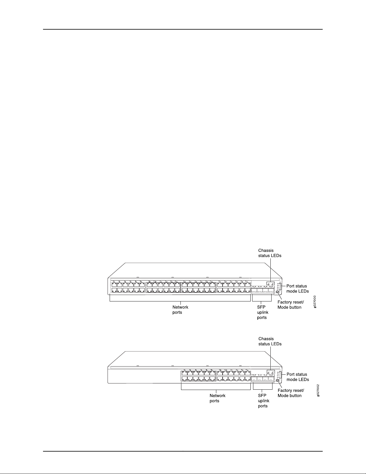
Front Panel of an EX2200 Switch
The front panel of an EX2200 switch except the EX2200-C switch models consists of
the following components:
•
Network ports—depending on the switch model, either of:
•
24 or 48 10/100/1000BASE-T Gigabit Ethernet ports, with Power over Ethernet
(PoE) not available in EX2200-24T, EX2200-24T-DC, and EX2200-48T models
•
24 or 48 10/100/1000BASE-T Gigabit Ethernet ports, with Power over Ethernet
(PoE) available in EX2200-24P and EX2200-48P models
•
4 built-in SFP uplink ports. You can use these ports to forward network traffic or
configure them into Virtual Chassis ports (VCPs) to interconnect EX2200 switches
into a Virtual Chassis.
•
2 chassis status LEDs
•
4 port status mode LEDs
•
Factory reset/Mode button
Figure 1 on page 6 shows the front panel of an EX2200 switch with 48 Gigabit Ethernet
ports. Figure 2 on page 6 shows the front panel of an EX2200 switch with 24 Gigabit
Ethernet ports.
Figure 1: Front Panel of an EX2200 Switch with 48 Gigabit Ethernet Ports
Figure 2: Front Panel of an EX2200 Switch with 24 Gigabit Ethernet Ports
Copyright © 2017, Juniper Networks, Inc.6
Page 27
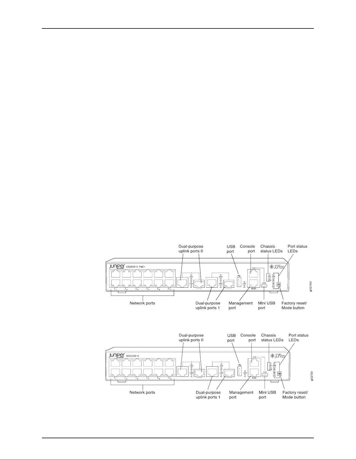
Chapter 1: System Overview
The front panel of an EX2200-C switch consists of the following components:
•
Network ports—depending on the switch model, either of:
•
12 10/100/1000BASE-T Ethernet ports, (PoE+) in EX2200-C-12P
•
12 10/100/1000BASE-T Ethernet ports, (non-PoE) in EX2200-C-12T
•
2 built-in dual-purpose uplink ports, each of which includes one 10/100/1000 RJ-45
Ethernet port and one SFP port
•
1 USB port
•
1 Mini-USB console port
•
1 RJ-45 console port
•
1 Management Ethernet port
•
2 chassis status LEDs
•
4 port status mode LEDs in PoE+ and 3 port status mode LEDs in non-PoE
•
Factory reset/Mode button
Figure 3 on page 7 shows the front panel of an EX2200-C switch with 12 Gigabit Ethernet
PoE+ ports and Figure 4 on page 7 shows the front panel of an EX2200-C switch with
12 Gigabit Ethernet non-PoE ports.
Figure 3: Front Panel of an EX2200-C Switch with 12 Gigabit Ethernet
Ports (PoE+)
Figure 4: Front Panel of an EX2200-C Switch with 12 Gigabit Ethernet
Ports (non-PoE)
7Copyright © 2017, Juniper Networks, Inc.
Page 28
g027001
USB
port
Management
Ethernet por t
Console RPS
port
port
Protective
earthing terminal
Air exhaust without fan
(closed on non-PoE models)
Air exhaust
with fan
AC power
cord inlet
ESD
point
EX2200-24-4G REV: X1
750-026464 REV: X3
MAC:00:23:9C:oE:19:00
Mfg.Date
20090227
MADEIN CHINA
Serial number
ID label
Air intake with fan for power supply
(fan on PoE models only)
EX2200 and EX2200-C Switches Hardware Guide
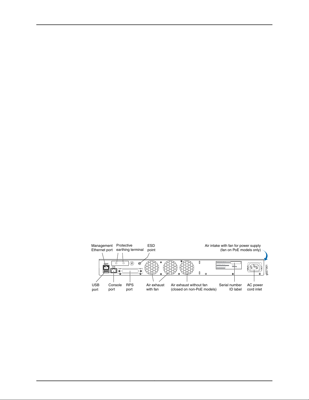
Rear Panel of an EX2200 Switch
The rear panel of the EX2200 switch except the EX2200-C switch models consists of
the following components:
•
Management Ethernet port
•
USB port
•
Console port
•
Protective earthing terminal
•
Redundant power system (RPS) port
•
ESD point
•
Air exhaust
•
Serial number ID label
•
AC power cord inlet or DC power terminals
Figure 5 on page 8 shows the rear panel of an EX2200 switch with an AC power supply.
All EX2200 switches except the EX2200-C switch model have three exhaust openings
on the rear panel. The two exhaust openings on the left have fans behind them and are
open. The exhaust opening on the right has no fan within it. This opening is exposed on
Power over Ethernet (PoE) models and sealed on non-PoE models. On PoE models, this
opening exhausts the air from the fan at the air intake for the power supply on the side
panel.
The power cord retainer clips extend out of the chassis by 3 in.
Figure 5: Rear Panel of an EX2200 Switch with AC Power Supply
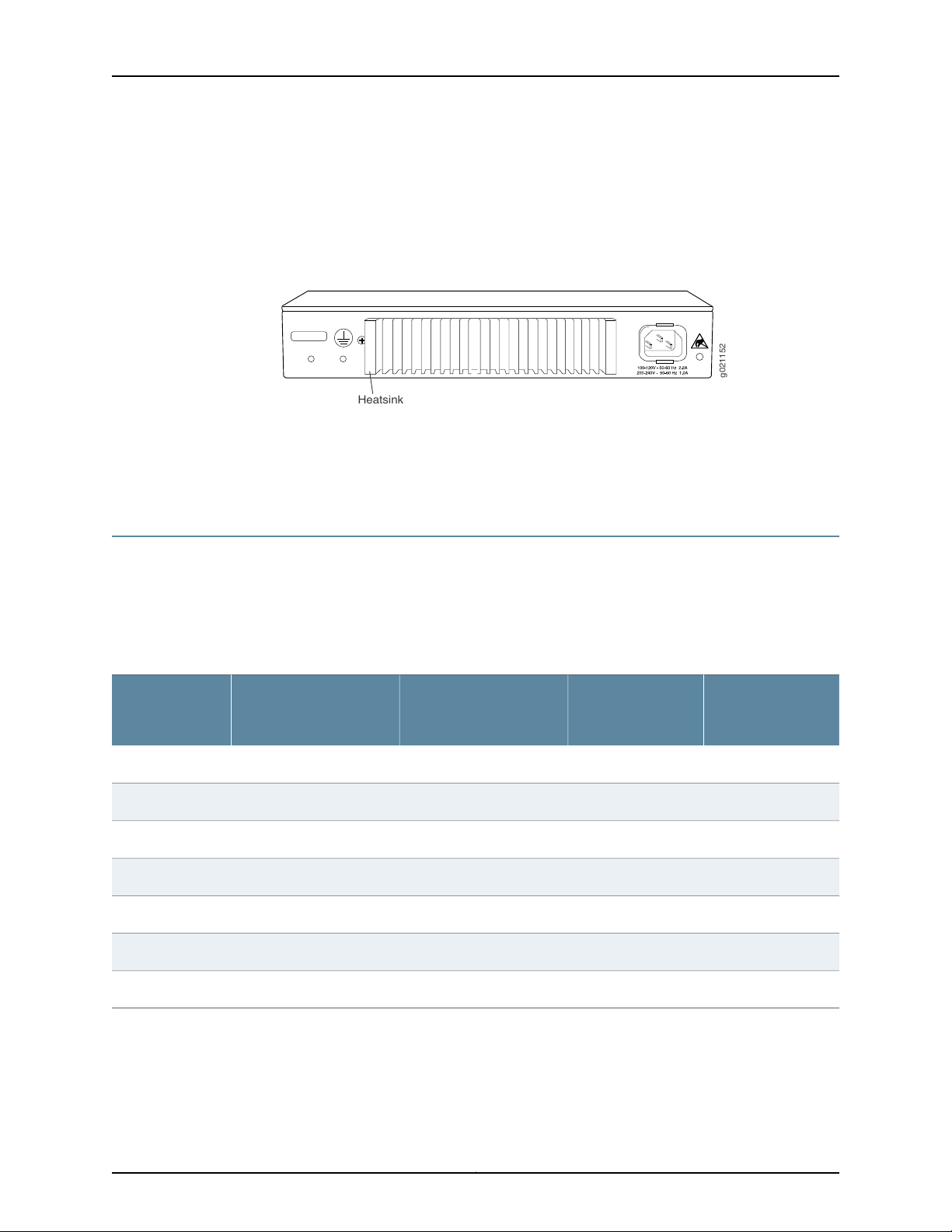
The rear panel of an EX2200-C switch consists of the following components:
•
Protective earthing terminal
•
ESD point
•
Serial number ID label
•
AC power cord inlet
•
Heatsink—only in PoE+ models
Copyright © 2017, Juniper Networks, Inc.8
Page 29
g021152
Heatsink
Chapter 1: System Overview
Figure 6 on page 9 shows the rear panel of an EX2200-C-12P switch with heatsink.
EX2200-C switches being fanless models have no exhaust openings. The switch has
vents on the top and on both the sides of the chassis. The PoE+ models have a heatsink
installed in the rear panel to dissipate the heat, while non-PoE models have no heatsink.
Figure 6: Rear Panel of an EX2200-C-12P Switch with Heatsink
Related
Documentation
EX2200 Switch Models on page 9•
• Site Preparation Checklist for EX2200 Switches on page 47
EX2200 Switch Models
The EX2200 switch is available with 12, 24, or 48 built-in network ports with full Power
over Ethernet (PoE)capability (all 12, 24, or 48 built-in network ports support PoE) or no
PoE capability. EX2200 switches with DC power supply do not provide PoE.
Table 3 on page 9 lists the EX2200 switch models.
Table 3: EX2200 Switch Models
Ports in Which PoE is
AvailableAccess PortsModel
Maximum System
PowerAvailablefor
PoE
First Junos OS
Release
11.3R1––12 Gigabit EthernetEX2200-C-12T-2G
11.3R1100 WAll 12 ports12 Gigabit EthernetEX2200-C-12P-2G
10.1R1––24 Gigabit EthernetEX2200-24T-4G
10.1R1405 WAll 24 ports24 Gigabit EthernetEX2200-24P-4G
Related
Documentation
10.1R1––24 Gigabit EthernetEX2200-24T-4G-DC
10.1R1––48 Gigabit EthernetEX2200-48T-4G
10.1R1405 WAll 48 ports48 Gigabit EthernetEX2200-48P-4G
EX2200 Switches Hardware Overview on page 3•
9Copyright © 2017, Juniper Networks, Inc.
Page 30

EX2200 and EX2200-C Switches Hardware Guide
EX2200 Switch Hardware and CLI Terminology Mapping
This topic describes the hardware terms used in EX2200 switch documentation and the
corresponding terms used in the Junos OS command line interface (CLI). See
Table 4 on page 10.
Table 4: CLI Equivalents of Terms Used in Documentation for EX2200 Switches
Hardware Item (as
displayed in the CLI)
Chassis
FPC (n)
Description (as
displayed in the CLI)
•
EX2200-C-12T-2G
•
EX2200-C-12P-2G
•
EX2200-24T-4G
•
EX2200-24P-4G
•
EX2200-24T-4G-DC
•
EX2200-48T-4G
•
EX2200-48P-4G
the Flexible PIC
Concentrator (FPC)
One of the following:
•
EX2200-C-12T-2G
•
EX2200-C-12P-2G
•
EX2200-24T-4G
•
EX2200-24P-4G
•
EX2200-24T-4G-DC
•
EX2200-48T-4G
•
EX2200-48P-4G
Value (as displayed
in the CLI)
Value of n is always 0.Abbreviated name of
Item in
Documentation
Switch chassis–One of the following:
The switch does not
have actual FPCs. In
this case, FPC refers to
the switch itself.
Additional
Information
“Chassis Physical
Specifications for
EX2200 Switches” on
page 13
Understanding Interface
Naming Conventions on
EX Series Switches
PIC (n)
Abbreviated name of
the Physical Interface
Card (PIC)
•
12x 10/100/1000
BASE-T
•
24x 10/100/1000
BASE-T
•
48x 10/100/1000
BASE-T
n is a value in the range
of 0–1.
PIC 0One of the following:
The switch does not
have actual PIC
devices; see entries for
PIC 0 through PIC 1 for
the equivalent item on
the switch.
Built-in network ports
on the front panel of
the switch
Copyright © 2017, Juniper Networks, Inc.10
Understanding Interface
Naming Conventions on
EX Series Switches
“EX2200 Switches
Hardware Overview”
on page 3
Page 31

Chapter 1: System Overview
Table 4: CLI Equivalents of Terms Used in Documentation for EX2200 Switches (continued)
Hardware Item (as
displayed in the CLI)
Xcvr (n)
Fan
Description (as
displayed in the CLI)
•
2x (10/100/1000
BASE-T or GE SFP)
or
•
2x (100/1000
BASE-X)
•
4x GE SFP
Abbreviated name of
the transceiver
NOTE: EX2200-C
switches are fanless
models.
Value (as displayed
in the CLI)
PIC 1One of the following:
to the number of the
port in which the
transceiver is installed.
Item in
Documentation
Built-in uplink ports
and dual-purpose
uplink ports on the
front panel of the
switch
Optical transceiversn is a value equivalent
AC power supplyValue of n is always 0.Built-in power supplyPower supply (n)
Fan–Fan
Additional
Information
“EX2200 Switches
Hardware Overview”
on page 3
“Pluggable
Transceivers
Supported on EX2200
Switches” on page 67
“Power Supply in
EX2200 Switches” on
page 23
“Cooling System and
Airflow in an EX2200
Switch” on page 19
Related
Documentation
• EX2200 Switches Hardware Overview on page 3
11Copyright © 2017, Juniper Networks, Inc.
Page 32

EX2200 and EX2200-C Switches Hardware Guide
Copyright © 2017, Juniper Networks, Inc.12
Page 33

CHAPTER 2
Chassis Components and Descriptions
•
Chassis Physical Specifications for EX2200 Switches on page 13
•
Chassis Status LEDs in EX2200 Switches on page 14
•
Management Port LEDs in EX2200 Switches on page 15
•
Network Port and Uplink Port LEDs in EX2200 Switches on page 16
Chassis Physical Specifications for EX2200 Switches
The EX2200 switch chassis is a rigid sheet-metal structure that houses the hardware
components. Table 5 on page 13 summarizes the physical specifications of the EX2200
switch chassis.
Table 5: Physical Specifications of the EX2200 Switch Chassis
EX2200-C ValueEX2200 ValueDescription
1.75 in. (4.4 cm)1.75 in. (4.45 cm)Chassis height
Chassis width
Weight
Documentation
Related
•
17.5 in. (44.5 cm)
•
19 in. (48.2 cm) with mounting brackets
attached
10.5 in. (26.7 cm)Chassis depth
•
EX2200-24T: 6 lb (2.7 kg)
•
EX2200-24P: 8 lb (3.6 kg)
•
EX2200-24T-DC: 6 lb (2.7 kg)
•
EX2200-48T: 8 lb (3.6 kg)
•
EX2200-48P: 10 lb (4.5 kg)
•
10.6 in. (26.92 cm)
•
19 in. (48.26 cm) with mounting brackets
•
EX2200-C-12T: 9.0 in. (22.8 cm)
•
EX2200-C-12P: 9.4 in. (23.8 cm)
•
EX2200-C-12T: 4.6 lb (2.1 kg)
•
EX2200-C-12P: 6.4 lb (2.9 kg)
Rack Requirements on page 55•
• Cabinet Requirements on page 56
• Mounting an EX2200 Switch on page 90
• Installing and Connecting an EX2200 Switch on page 89
13Copyright © 2017, Juniper Networks, Inc.
Page 34
g027003
0 1 2
SYS
ALM
SPD
DX
EN
POE
3
Chassis
status LEDs
g021153
Chassis
status LEDs
EX2200 and EX2200-C Switches Hardware Guide
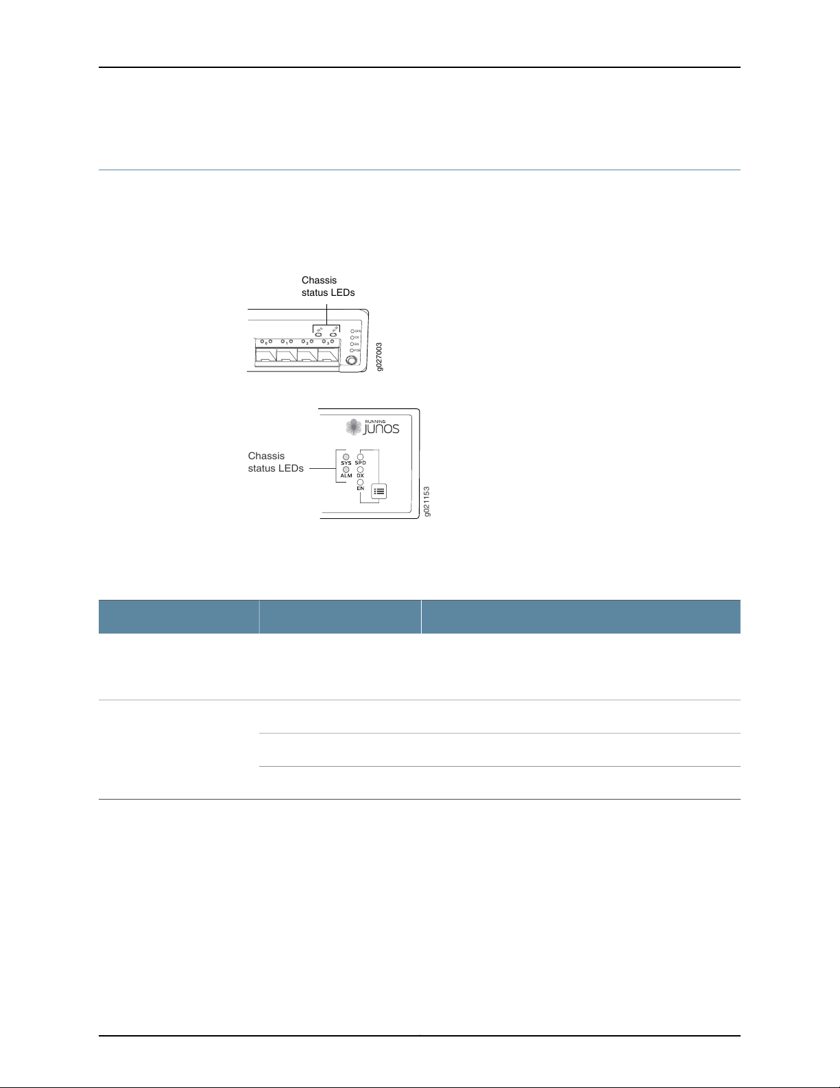
Chassis Status LEDs in EX2200 Switches
The front panel of an EX2200 switch has two chassis status LEDs labeled SYS and ALM
on the far right side of the panel. See Figure 7 on page 14 and Figure 8 on page 14.
Figure 7: Chassis Status LEDs in an EX2200 Switch Except the EX2200-C
Switch
Figure 8: Chassis Status LEDs in an EX2200-C Switch
Table 6 on page 14 describes the chassis status LEDs in an EX2200 switch, their colors
and states, and the status they indicate.
Table 6: Chassis Status LEDs in an EX2200 Switch
State and DescriptionColorLED Label
GreenSYS
A major alarm (red) indicates a critical error condition that requires immediate action.
A minor alarm (amber) indicates a noncritical condition that requires monitoring or
maintenance. A minor alarm that is left unchecked might cause interruption in service or
performance degradation.
Both LEDs can be lit simultaneously.
•
•
•
There is no alarm or the switch is halted.UnlitALM
There is a minor alarm.Amber
There is a major alarm.Red
On steadily—The switch is functioning normally.
Blinking—The switch is booting.
Off—The switch is powered off or is halted.
You can view the colors of the two LEDs remotely through the CLI by issuing the
operational mode command show chassis led.
Copyright © 2017, Juniper Networks, Inc.14
Page 35
g027006
Link/Activity
LED
Status
LED
g021155
Status
LED
Link/Activity
LED
Chapter 2: Chassis Components and Descriptions
Related
Documentation
EX2200 Switches Hardware Overview on page 3•
• Chassis Component Alarm Conditions on EX2200 Switches on page 166
• Checking Active Alarms with the J-Web Interface on page 172
• Understanding Alarm Types and Severity Levels on EX Series Switches on page 165
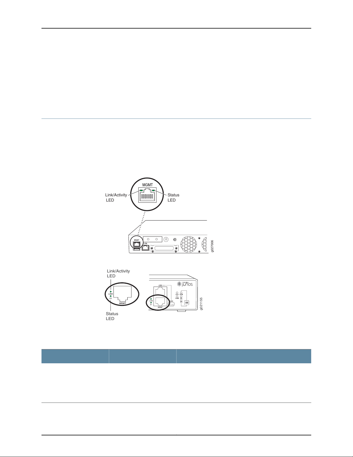
Management Port LEDs in EX2200 Switches
The management port on an EX2200 switchhas two LEDs that indicate link/activityand
port status. The EX2200 switches except the EX2200-C switch models have the
management port on the rear panel and the EX2200-C switchhas the management port
on the front panel. See Figure 9 on page 15 and Figure 10 on page 15.
Figure 9: LEDs on the Management Port on an EX2200 Switch Except the
EX2200-C Switch Model
Figure 10: LEDs on the Management Port on an EX2200-C Switch
Table 7 on page 15 describes the Link/Activity LED.
Table 7: Link/Activity LED on the Management Port on EX2200 Switches
State and DescriptionColorLED
•
GreenLink/Activity
Blinking—The port and the link are active, and there is link
activity.
•
On steadily—The port and the link are active, but there is no
link activity.
•
Off—The port is not active.
15Copyright © 2017, Juniper Networks, Inc.
Page 36
g041128
Link/
Activity
Status
EX2200 and EX2200-C Switches Hardware Guide
Table 8 on page 16 describes the Status LED.
Table 8: Status LED on the Management Port on EX2200 Switches
State and DescriptionColorLED
Indicates the speed. The speed indicators are:
•
One blink per second—10 Mbps
•
Two blinks per second—100 Mbps
Related
GreenStatus
Connecting a Device to a Network for Out-of-Band Management on page 127•
Documentation
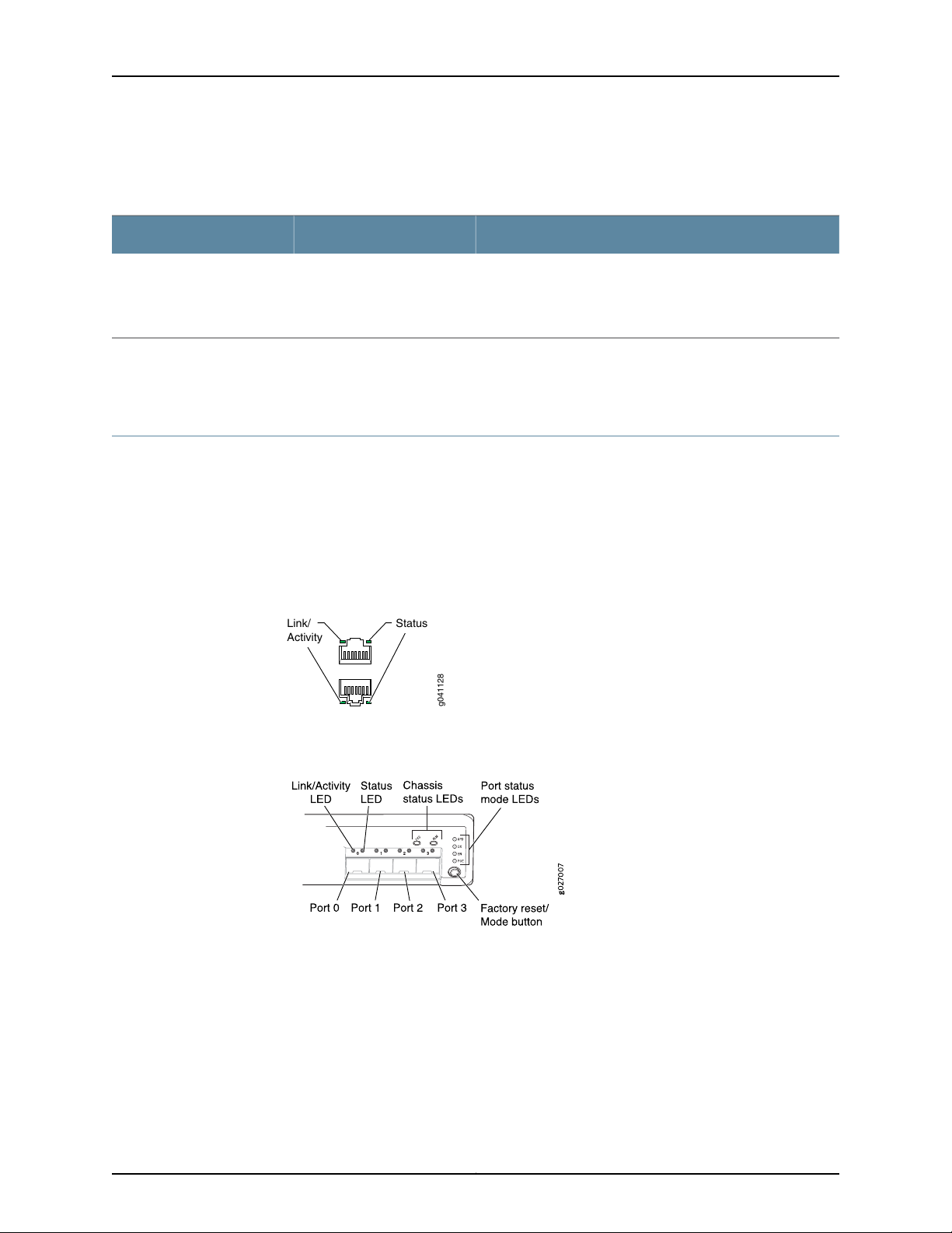
Network Port and Uplink Port LEDs in EX2200 Switches
Each network port and uplink port on the front panel of an EX2200 switch has two LEDs
that indicate link/activity and port status. Each dual-purpose uplink port in an EX2200-C
switch has two pairs of LEDs that indicate the link/activity status, one pair for each of
the two ports that constitute the dual-purpose uplink port. See Figure 11 on page 16,
Figure 12 on page 16, and Figure 13 on page 17.
Figure 11: LEDs on the Network Port
Figure 12: LEDs on the Uplink Ports and Port Status Mode LEDs in an
EX2200 Switch Except the EX2200-C Switch Model
Copyright © 2017, Juniper Networks, Inc.16
Page 37
Chapter 2: Chassis Components and Descriptions
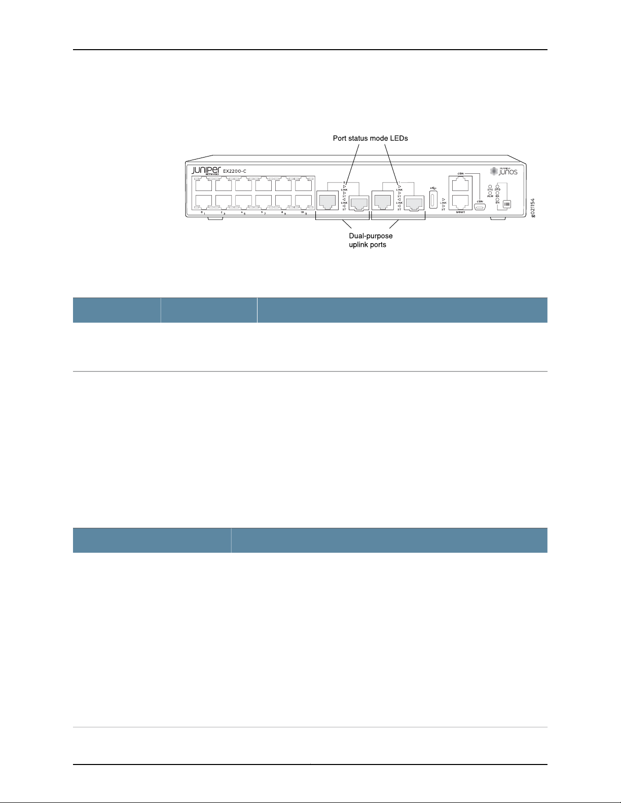
Figure 13: Port Status Mode LEDs of the Dual-Purpose Uplink Ports of an
EX2200-C Switch
Table 9 on page 17 describes the Link/Activity LED.
Table 9: Link/Activity LED on the Network Ports and Uplink Ports in EX2200 Switches
State and DescriptionColorLED
•
GreenLink/Activity
Blinking—The port and the link are active, and there is link activity.
•
On steadily—The port and the link are active, but there is no link activity.
•
Off—The port is not active.
In Figure 11 on page 16, Figure 12 on page 16, and Figure 13 on page 17 show the LEDs that
indicatethe status of one of the fourport parameters—speed, duplex mode, administrative
status, and Power over Ethernet (PoE) status. Use the Factory reset/Mode button below
the LED labeled POE on the far right side of the front panel to toggle the Status LED to
show the different port parameters. You can tell which port parameter is indicated by
the Status LED by looking at which port status mode LED (SPD, DX, EN, and POE) is lit.
(See Figure 12 on page 16).
Table 10 on page 17 describes the Status LED.
Table 10: Status LED on the Network Ports, Uplink Ports, and Dual-Purpose Uplink Ports in
EX2200 Switches
State and DescriptionPort Parameters
Speed
Indicates the speed. The speed indicators for network ports are:
•
One blink per second—10 Mbps
•
Two blinks per second—100 Mbps
•
Three blinks per second—1000 Mbps
The speed indicators for uplink ports are:
•
On steadily—1000 Mbps
•
Off—10/100 Mbps
The speed indicators for dual-purpose uplink ports of EX2200-C switch model are:
•
One blink per second—10 Mbps
•
Two blinks per second—100 Mbps
•
Three blinks per second—1000 Mbps
17Copyright © 2017, Juniper Networks, Inc.
Page 38

EX2200 and EX2200-C Switches Hardware Guide
Table 10: Status LED on the Network Ports, Uplink Ports, and Dual-Purpose Uplink Ports in
EX2200 Switches (continued)
State and DescriptionPort Parameters
Duplex mode
Administrative status
PoE status
Indicates the duplex mode. The status indicators are:
•
On steadily—Port is set to full-duplex mode.
•
Off—Port is set to half-duplex mode.
Indicates the administrative status. The status indicators are:
•
On steadily—Port is administratively enabled.
•
Off—Port is administratively disabled.
Indicates the PoE status. The status indicators for network ports are:
•
On steadily—PoE is availableon the port, a device that draws power from the port
is connected to the port, and the device is drawing power from the port.
•
Blinking—PoEis available on the port, but no power is drawn from the port because
of one of the following:
•
No device that draws power from the port is connected to the port.
•
A device that drawspowerfrom the port is connectedto the port, but the device
is not drawing any power from the port.
•
Off—PoE is not available on the port.
NOTE: PoE Status LED is available on the following EX2200 switch models:
•
EX2200-C-12P
•
EX2200-24P
•
EX2200-48P
PoE is not availableon uplink ports; therefore,the LED for those ports is always unlit.
Related
Documentation
You can tell which port parameter is indicatedby the StatusLED on network ports, uplink
ports, and dual-purpose uplink ports by issuing the operational mode command show
chassis led.
• EX2200 Switches Hardware Overview on page 3
• Configuring Gigabit Ethernet Interfaces (CLI Procedure)
• Configuring Gigabit Ethernet Interfaces (J-Web Procedure)
Copyright © 2017, Juniper Networks, Inc.18
Page 39

CHAPTER 3
Cooling System and Airflow
•
Cooling System and Airflow in an EX2200 Switch on page 19
Cooling System and Airflow in an EX2200 Switch
Thecooling system in EX2200 switches,exceptEX2200-C, the compact, fanless models,
consists of two fans along the rear of the chassis that provide side-to-rearchassis cooling.
In the PoE models of these switches, there is an additional fan in the power supply.
In the EX2200-C switch the cooling is done by the vents on top and sides of the chassis
in non-PoE models and by heatsinks in PoE+ models. Do not block the vents on the
chassis. Doing this can lead to overheating of the switch chassis
This topic describes:
•
Airflow Direction in Non-PoE Models of EX2200 Switches, Except for the EX2200-C
Models on page 19
•
Airflow Direction in PoE Models of EX2200 switches, Except for the EX2200-C
Models on page 20
Airflow Direction in Non-PoE Models of EX2200 Switches, Except for the EX2200-C Models
Figure 14 on page 20 shows the airflow in non-PoE models of EX2200 switches, except
for the EX2200-C models.
19Copyright © 2017, Juniper Networks, Inc.
Page 40
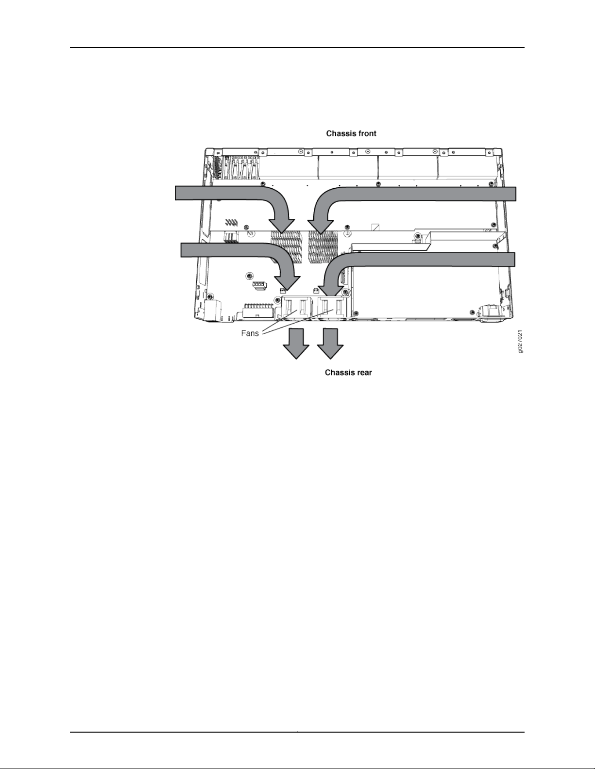
EX2200 and EX2200-C Switches Hardware Guide
Figure 14: Airflow Through Non-PoE Models of EX2200 Switches Except
the EX2200-C Switch Model
Airflow Direction in PoE Models of EX2200 switches, Except for the EX2200-C Models
Figure 15 on page 21 shows the airflow in PoE models of EX2200 switches, except
EX2200-C models.
Copyright © 2017, Juniper Networks, Inc.20
Page 41
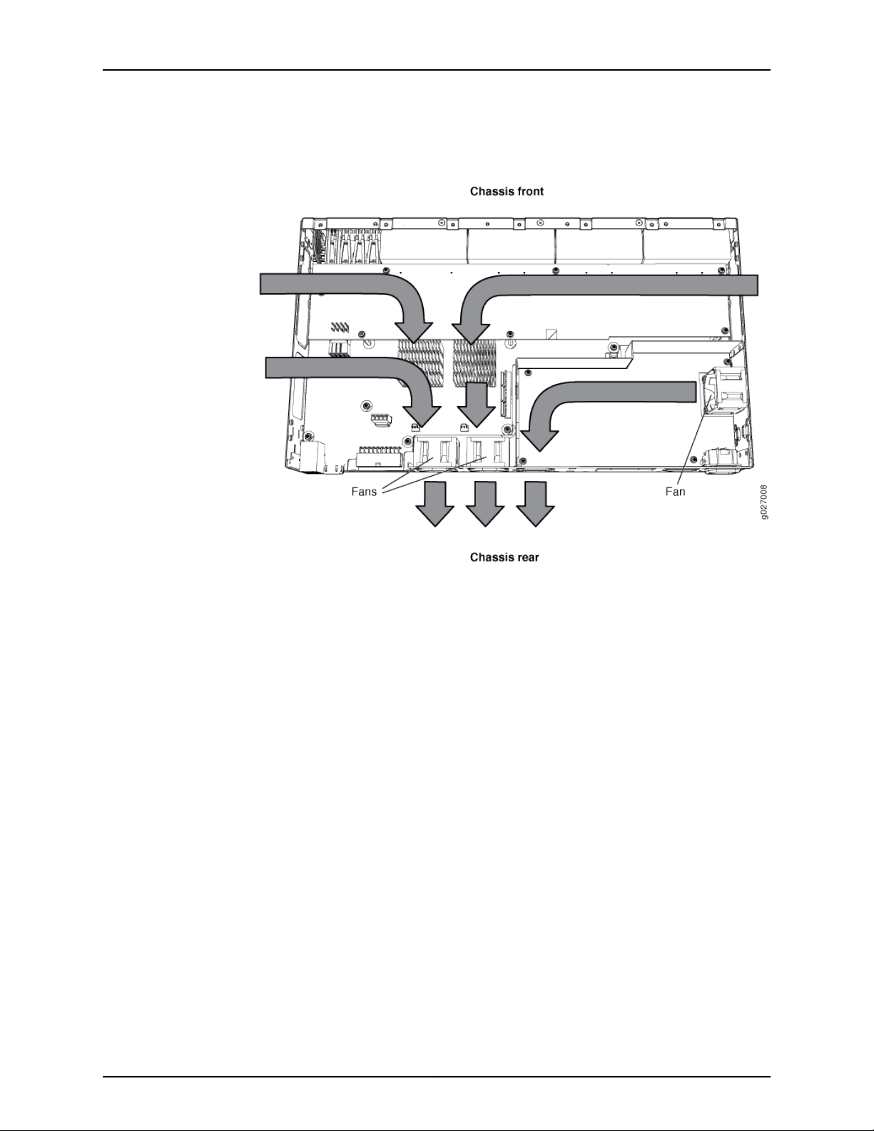
Chapter 3: Cooling System and Airflow
Figure 15: Airflow Through PoE Models of EX2200 Switches Except the
EX2200-C Switch Models
Related
Documentation
Under normal operating conditions, the fans operate at a moderate speed to reduce
noise. Temperature sensors in the chassis monitor the temperature within the chassis.
If any fan fails or if the temperature inside the chassis rises above the threshold, the
switch raises an alarm and all functioning fans operate at a higher speed than normal.
If the temperature inside the chassis rises above the threshold, the switch shuts down
automatically.
• EX2200 Switches Hardware Overview on page 3
• Chassis Status LEDs in EX2200 Switches on page 14
• Understanding Alarm Types and Severity Levels on EX Series Switches on page 165
• Prevention of Electrostatic Discharge Damage on page 211
21Copyright © 2017, Juniper Networks, Inc.
Page 42

EX2200 and EX2200-C Switches Hardware Guide
Copyright © 2017, Juniper Networks, Inc.22
Page 43

CHAPTER 4
Power Supplies
•
Power Supply in EX2200 Switches on page 23
Power Supply in EX2200 Switches
The power supply in EX2200 switches is built in along the rear panel of the chassis, with
an AC power cord inlet or DC power terminals on the rear panel to connect power to the
switch.
Table 11 on page 23 lists the power consumed by each EX2200 switch model. The
maximum power available on a PoE port is 30 W for switches running Junos OS Release
10.3 or later and 15.4 W for switches running Junos OS Release 10.2 or earlier.
Table 11: Power Consumed by EX2200 Switches
Related
Documentation
Number of PoE-Enabled
PortsModel Number
12EX2200-C-12P
24EX2200-24P
48EX2200-48P
• AC Power Cord Specifications for EX2200 Switches on page 62
• EX2200 Switches Hardware Overview on page 3
• Power Specifications for EX2200 Switches on page 61
Maximum Power
Consumed by the Switch
drawn)
drawn)
drawn)
Maximum PoE Power
Available
–30 W–EX2200-C-12T
100 W30 W (when no PoE power is
–50 W–EX2200-24T
405 W60 W (when no PoE power is
–50 W–EX2200-24T-DC
–76 W–EX2200-48T
405 W91 W (when no PoE power is
23Copyright © 2017, Juniper Networks, Inc.
Page 44

EX2200 and EX2200-C Switches Hardware Guide
• Connecting AC Power to an EX2200 Switch on page 121
• Connecting DC Power to an EX2200 Switch on page 123
• Connecting Earth Ground to an EX Series Switch on page 115
Copyright © 2017, Juniper Networks, Inc.24
Page 45

CHAPTER 5
Viewing System Information
•
Dashboard for EX Series Switches on page 25
Dashboard for EX Series Switches
NOTE: This topic applies only to the J-Web Application package.
When you log in to the J-Web user interface, the dashboard for the Juniper Networks EX
Series Ethernet Switches appears. Use the dashboard to view system information.
The Update Available window appears if there is a latestupdate of the J-WebApplication
package available on the Juniper Networks server. This window is enabled by the auto
update feature of J-Web.
NOTE:
•
The Update Available window will not appear when you log in, if you have
not selected the Check for updates automaticallyon every login in the Update
Preference section in the Maintain > Update J-Web side pane. By default,
the Check for update automatically on every login is selected.
•
If you choose Update Later, you can update to the latestJ-WebApplication
package by clicking the orange icon next to Update Available on the top
pane of the J-Web interface or through Maintain > Update J-Web.
The dashboard comprises a graphical chassis viewer and four panels.
This topic describes:
•
Graphical Chassis Viewer on page 26
•
System Information Panel on page 27
•
Health Status Panel on page 29
•
Capacity Utilization Panel on page 31
•
Alarms Panel on page 31
25Copyright © 2017, Juniper Networks, Inc.
Page 46

EX2200 and EX2200-C Switches Hardware Guide
•
File System Usage on page 32
•
Chassis Viewer on page 32
Graphical Chassis Viewer
The Dashboard panel displays a graphical view of the chassis of a switch. In a Virtual
Chassis, it displays a graphical view of each member switch.
In a Virtual Chassis, the defaultvalues are shown on the Dashboard panel when no chassis
image is clicked. The panel displays the value for a switch if you click its image.
NOTE: If the member switch is not present, inactive, or not provisioned, you
cannot expand the member switch image.
In J-Web Application package Release 14.1X53-A2, you can form a Virtual
Chassisusing EX4600 and EX4300 switches. Whenin a mixed VirtualChassis
consisting of EX4600 switches and EX4300 switches, the EX4600 switches
can be the master,backup, or in the linecard role, while the EX4300 switches
must be in the linecard role.
Table 12 on page 26 lists the details that are displayed on each member switch.
Table 12: Details of a Virtual Chassis Member Switch
ExampleDetails
EX3300Model number of the member switch
Assigned ID that applies to the entire Virtual Chassis
configuration
Role of the member switch
Status of the member switch
The status of the member switch is displayed on the image of the switch. If the member
switchappears dimmed, it means the switch is not present, is inactive, or is not provisioned
in the Virtual Chassis. If the member switch does not appear dimmed, it means the switch
is present and is active.
ID 2
NOTE: If the member switch is not provisioned, the serial number
of the switch is displayed instead of its ID.
Master
Possible roles are: Master, Backup, or Linecard
Prsnt
Possible statuses are: Prsnt, NotPrsnt, Inactive, or Unprvsnd
Table 13 on page 27 describes the possible status of a member switch.
Copyright © 2017, Juniper Networks, Inc.26
Page 47

Table 13: Status of a Member Switch in a Virtual Chassis
It means the member switchIt appears asIf the member switch is
Chapter 5: Viewing System Information
Not present
Inactive
Not provisioned
PrsntPresent
NotPrsnt
dimmed and
Inactive
dimmed and
Unprvsnd
Has established physical and logical connections with Virtual
Chassis member switches.
Has been disconnected from the existing Virtual Chassis.dimmed and
Has established physical connections, but is unable to establish
logical connections.
Cannot synchronize with the existing preprovisioned Virtual
Chassis.
Click Rear View for a graphical view of the rear panel of the switch.
Click Preferences to choose which panels must be displayed and set the refresh interval
forchassis viewer information.Click OK to save your changes and return to the dashboard
or click Cancel to return to the dashboard without saving changes.
NOTE: You can drag the various panels to different locations in the J-Web
window.
System Information Panel
Table 14: System Information
System name
Device model
DescriptionField
Indicates the local name of the EX Series switch. The local
name of the EX Series switches changes when an individual
image is clicked.
Indicatesthe model of the EX Series switch. In a Virtual Chassis
configuration,toindicatethe model of a switch, click the image
of that switch.
NOTE: In a Virtual Chassis setup for an EX6210, EX8208, or
EX8216 switch, the Device model field displays details of the
master Routing Engine. To view details of a member, select it.
27Copyright © 2017, Juniper Networks, Inc.
Page 48

EX2200 and EX2200-C Switches Hardware Guide
Table 14: System Information (continued)
DescriptionField
Inventory details
Indicates the following:
•
For EX3200 switches; and for EX2200, EX2200-C, EX3300,
EX4200, EX4300, EX4500, EX4550, and EX4600 switches
that are not configured as Virtual Chassis, the value
displayed in Inventory details field is always 1 FPC. FPC is a
legacy term for a slot in a large Juniper Networks chassis;
which simply refers to the standalone switch.
•
For EX2200 and EX2200-C switches configuredas a Virtual
Chassis, the value displayed in the Inventory details field is
1–4 FPC, with the number corresponding to the number of
member switches.
•
For EX3300 switches configured as a Virtual Chassis, the
value displayed in the Inventory details field is 1–6 FPC, with
the number corresponding to the number of member
switches.
NOTE: For Junos OS Release14.1X53-D10and later,EX3300
switches configured as a Virtual Chassis display the value
1–10 FPC in the Inventory details field.
•
For EX4200, EX4500, EX4550, and EX4600 switches
configured as a Virtual Chassis, the value displayed in the
Inventory details field is 1–10 FPC, with the number
corresponding to the number of member switches.
•
For EX6210 switches, the values displayed in the Inventory
details field are 1–2 CB and 1–9 FPC. CB, or Control Board,
refers to the SRE module. FPC refers to line cards and the
FPC within the CB.
•
For an EX8208 switch, the values displayed in Inventory
details field are 1–3 CB and 0–8 FPC. CB, or Control Board,
refers to SRE and SF modules. FPC refers to line cards.
•
For EX8216 switches, the values displayed in Inventory
details field are 1–2 CB and 0–16 FPC. CB, or Control Board,
refers to RE modules and FPC refers to line cards.
•
For an XRE200 External Routing Engine in an EX8200 Virtual
Chassis, the value displayed in Inventory details is 1 XRE.
XRE refers to RE modules. For XRE200 External Routing
Engines configured as a Virtual Chassis, the values displayed
in Inventory details are 1–2 XRE and 0–4 LCC, where LCC
refers to the EX8200 line card chassis.
Junos image
Boot image
Indicatesthe version of the Junos OS image. In a Virtual Chassis
configuration, the Junos OS image of the master switch is
displayed by default. To display the Junos OS image of a
specific switch, click the image of that switch.
Indicatesthe version of the boot image that is used. In a Virtual
Chassis configuration, the boot image of the master switch is
displayed by default. To display the boot image of a specific
switch, click the image of that switch.
Copyright © 2017, Juniper Networks, Inc.28
Page 49

Table 14: System Information (continued)
Chapter 5: Viewing System Information
DescriptionField
Device uptime
Indicates the time since the last reboot. In a Virtual Chassis
configuration,to displaythe uptime of the specific switch, click
the image of that switch.
Indicates the time when the switch was last configured.Last configured time
Health Status Panel
Table 15: Health Status
DescriptionField
EX2200, EX2200-C, EX3200, EX3300, EX4200, and EX4300 Switches
Memory util.
Flash
Indicates the memory used in the Routing Engine. In a Virtual Chassis configuration, the memory
utilization value of the master Routing Engine is displayed.
NOTE: In EX4300 and EX4600 Virtual Chassis, to display the Routing Engine memory utilization of
the master or backup, click the respective image. J-Web is supported on EX4600 switches only in
J-Web Application package Release 14.1X53-A2.
Indicates the usage and capacity of internal flash memory and any external USB flash drive.
NOTE: In EX4300 Virtual Chassis, the flash memory utilization of the master switch is displayed by
default. To display the flash memory utilization along with the internal and external flash memory
utilization details for each switch or line card, mouse over individual switch or line card images.
In EX4600 Virtual Chassis, to display the flashmemory utilization along with the internal and external
flash memory utilization details of each switch or line card mouse over the green-colored indicator.
Temp.
CPU load
Indicates the chassis temperature status. Temperatures are listed in Celsius and the corresponding
Fahrenheit values.
NOTE: The Temp field is unavailable for a standalone EX2200-C switch.
The Temp field is dynamically available for an EX2200 Virtual Chassis switch based on the model
of the member clicked.
NOTE: In EX4300 Virtual Chassis, the temperature of the master Routing Engine is displayed by
default. To display the temperature of the Routing Engine of any switch, click the image of that
switch.
In EX4600 Virtual Chassis, to display the temperature of the Routing Engine of each switch, mouse
over the green-colored indicator.
Indicates the average CPU usage over 15 minutes. In a Virtual Chassis configuration, on loading the
master or backup switch, the CPU load for that switch's Routing Engine is displayed by default. To
display the CPU load for a specific switch's Routing Engine, click the image of that switch.
29Copyright © 2017, Juniper Networks, Inc.
Page 50

EX2200 and EX2200-C Switches Hardware Guide
Table 15: Health Status (continued)
DescriptionField
Fan status
Indicates the status of the fans in the fan tray. The possible values are OK, Failed, and Absent. In a
Virtual Chassis configuration, the fan status of the master switch is displayed by default. To display
the fan status for any switch , click the image of that switch.
NOTE: The Fan status field is unavailable for a standalone EX2200-C switch.
The Fan status field is dynamically available for an EX2200 Virtual Chassis switch based on the
model of the member clicked.
In EX4600 Virtual Chassis, mouse over the fan icon to display the fan status of all the switches.
EX4500 and EX4550 Switches
Memory util.
Temp.
Fan status
Indicates the memory used in the Routing Engine. In a Virtual Chassis configuration, the memory
utilization value of the master Routing Engine is displayed.
Indicates the usage and capacity of internal flash memory and any external USB flash drive.Flash
Indicates the chassis temperature status. Temperatures in the dashboard are listed in Celsius and
the corresponding Fahrenheit values.
NOTE: The Temp field is unavailable for an EX4500 switch.
Indicates the average CPU usage over 15 minutes.CPU load
Indicates the status of the fans in the fan tray. The possible values are OK, Failed, and Absent. This
field also indicates the direction of airflow of the fan tray. The possible values are Front to back and
Back to front.
EX6210 Switches
Memory util.
EX8208 Switches
Memory util.
EX8216 Switches
Indicates the memory used in the master Routing Engine. Click the backup Routing Engine to view
the memory used in the backup Routing Engine.
Indicates the average CPU usage over 15 minutes.CPU load
Indicates the usage and capacity of internal flash memory and any external USB flash drive.Flash
Indicates the status of the fans in the fan tray. The possible values are OK, Failed, and Absent.Fan status
Indicatesthememory used in the externalRoutingEngine. In an EX8200 Virtual Chassis, the memory
utilization value of the XRE200 External Routing Engine in the master role is displayed. Click the
XRE200 External Routing Engine in the backup role to view the memory used in the backup external
Routing Engine.
Indicates the average CPU usage over 15 minutes.CPU load
Indicates the usage and capacity of internal flash memory and any external USB flash drive.Flash
Copyright © 2017, Juniper Networks, Inc.30
Page 51

Table 15: Health Status (continued)
DescriptionField
Chapter 5: Viewing System Information
Memory util.
Indicatesthememory used in the externalRoutingEngine. In an EX8200 Virtual Chassis, the memory
utilization value of the XRE200 External Routing Engine in the master role is displayed. Click the
XRE200 External Routing Engine in the backup role to view the memory used in the backup external
Routing Engine.
Indicates the average CPU usage over 15 minutes.CPU load
Indicates the usage and capacity of internal flash memory and any external USB flash drive.Flash
XRE200 External Routing Engines
Memory util.
Indicatesthememory used in the externalRoutingEngine. In an EX8200 Virtual Chassis, the memory
utilization value of the XRE200 External Routing Engine in the master role is displayed. Click the
backup XRE200 External RoutingEngine to view the memory used in backup external Routing Engine.
Indicates the average CPU usage over 15 minutes.CPU load
Indicates the usage and capacity of internal flash memory and any external USB flash drive.Flash
Indicates the status of the fans in the fan tray. The possible values are OK, Failed, and Absent.Fan Status
Capacity Utilization Panel
Table 16: Capacity Utilization
DescriptionField
Number of active ports
Total number of ports
Number of VLANs configured
Alarms Panel
Indicates the number of active ports in the switch. Configured
Virtual Chassis ports (VCPs) are considered as active ports.
Indicates the number of ports in the switch.
NOTE: In EX3300 and EX4600 Virtual Chassis, the total
number of ports of all of the switches is displayed.
Indicates the number of MAC table entries.Used-up MAC-Table entries
Indicatesthemaximum number of MAC table entries permitted.Supported MAC-Table entries
Indicates the number of VLANs configured.
NOTE: Only tagged VLANs are counted.
Indicates the maximum number of VLANs supported.Number of VLANs supported
Displaysinformation about the last five alarms raised in the system. For example, if there
are 5 major alarms, then details of all 5 major alarms are displayed. If there are 4 major
31Copyright © 2017, Juniper Networks, Inc.
Page 52

EX2200 and EX2200-C Switches Hardware Guide
alarms and 3 minor alarms, then details of the 4 major alarms and 1 minor alarm are
displayed. Major alarms are displayed in red and minor alarms are displayed in yellow.
In an EX8200 Virtual Chassis, the top 5 alarms for the master external Routing Engine
are displayed by default. If you select an EX8200 member switch of the Virtual Chassis,
the top 5 alarms for that member switch are displayed.
File System Usage
To display the file system storage details of a switch in the backup or linecard role, click
the image of that switch.
Chassis Viewer
Click the Rear View button to see the back of the chassis image. Click the Front View
button to see the front of the chassis image. In a Virtual Chassis configuration, the Rear
View button is disabled if the switch is not selected.
•
Table 17 on page 32—Describes the chassis viewer for EX2200 switches.
•
Table 18 on page 33—Describes the chassis viewer for EX2200-C switches.
•
Table 19 on page 33—Describes the chassis viewer for EX3200, EX3300, and EX4200
switches.
•
Table 20 on page 35—Describes the chassis viewer for EX4300 switches.
•
Table 21 on page 36—Describes the chassis viewer for EX4500 switches.
•
Table 22 on page 37—Describes the chassis viewer for EX4550 switches.
•
Table 23 on page 39—Describes the chassis viewer for EX4600 switches.
•
Table 24 on page 39—Describes the chassis viewer for EX6210 switches.
•
Table 25 on page 40—Describes the chassis viewer for EX8208 switches.
•
Table 26 on page 42—Describes the chassis viewer for EX8216 switches.
•
Table 27 on page 42—Describes the chassis viewer for the XRE200 External Routing
Engines.
Table 17: Chassis Viewer for EX2200 Switches
DescriptionField
Front View
Interface status
In the image, the following colors denote the interface status:
•
Green—Interface is up and operational.
•
Yellow—Interface is up but is nonoperational.
•
Gray—Interface is down and nonoperational.
Mouse over the interface (port) to view more information.
Rear View
Copyright © 2017, Juniper Networks, Inc.32
Page 53

Table 17: Chassis Viewer for EX2200 Switches (continued)
DescriptionField
Chapter 5: Viewing System Information
Management (me0) port
Console port
USB port
The management port is used to connect the switchto a management device for out-of-band
management.
The console port is used to connect the switch to a management console or to a console
server. (You might do this for initial switch configuration.)
Indicates the USB port for the switch.
NOTE: We recommend that you use USB flash drives purchased from Juniper Networks for
your EX Series switch.
Mouse over the fan tray icon to display name, status, and description information.Fan tray
Mouse over the power outlet icon to display name, status, and description information.Power supply
Table 18: Chassis Viewer for EX2200-C Switches
DescriptionField
Front View
Interface status
In the image, the following colors denote the interface status:
•
Green—Interface is up and operational.
•
Yellow—Interface is up but is nonoperational.
•
Gray—Interface is down and nonoperational.
Mouse over the interface (port) to view more information.
Management (me0) port
Console port
USB port
The management port is used to connect the switch to a management device for out-of-band
management.
The console port is used to connect the switch to a management console or to a console
server. (You might do this for initial switch configuration.)
Indicates the USB port for the switch.
NOTE: We recommend that you use USB flash drives purchased from Juniper Networks for
your EX Series switch.
Rear View
Mouse over the power outlet icon to display name, status, and description information.Power supply
Table 19: Chassis Viewer for EX3200, EX3300, and EX4200 Switches
DescriptionField
Front View
33Copyright © 2017, Juniper Networks, Inc.
Page 54

EX2200 and EX2200-C Switches Hardware Guide
Table 19: Chassis Viewer for EX3200, EX3300, and EX4200 Switches (continued)
DescriptionField
Interface status
In the image, the following colors denote the interface status:
•
Green—Interface is up and operational.
•
Yellow—Interface is up but is nonoperational.
•
Gray—Interface is down and nonoperational.
Mouse over the interface (port) to view more information.
For a Virtual Chassis configuration, select the switch to view the interface status.
If an SFP+ uplink module is installed in the switch, mouse over the port icon to display whether
the module is configured to operate in 1-gigabit mode or in 10-gigabit mode. If the module is
configured to operate in 1-gigabit mode, the tool tip information is displayed for all 4 ports. If the
module is configured to operate in 10-gigabit mode, the tool tip information is displayed only for
2 ports.
On an EX3300 switch with the 4x GE/XE SFP+ module, mouse over the port icon to display
whether the module is configured to operate in 1-gigabit mode or 10-gigabit mode.
For SFP, SFP+, and XFP ports, the interfaces appear dimmed if no transceiver is inserted. The
chassis viewer displays Transceiver not plugged-in when you mouse over the port icon.
LCD panel
LCD panel configured for the LEDs on the ports. Mouse over the icon to view the current character
display.
Rear View of the EX3200 Switch
Management (me0) port
The management port is used to connect the switch to a management device for out-of-band
management.
Console port
The console port is used to connect the switch to a management console or to a console server.
(You might do this for initial switch configuration.)
USB port
Indicates the USB port for the switch.
NOTE: We recommend that you use USB flash drives purchased from Juniper Networks for your
EX Series switch.
Mouse over the fan tray icon to display name, status, and description information.Fan tray
Mouse over the power supply icon to display name, status, and description information.Power supply
Rear View of the EX3300 and EX4200 Switch
Fan tray
Mouse over the fan tray icon to display name, status, and description information. For a Virtual
Chassis, the status of the fans of the selected member switch is displayed.
Virtual Chassis port
Displayed only when EX4200 switches are configured as a Virtual Chassis. The following colors
denote the Virtual Chassis port (VCP) status:
•
Green—VCP is up and operational.
•
Yellow—VCP is up but is nonoperational.
•
Gray—VCP is down and nonoperational.
Copyright © 2017, Juniper Networks, Inc.34
Page 55

Chapter 5: Viewing System Information
Table 19: Chassis Viewer for EX3200, EX3300, and EX4200 Switches (continued)
DescriptionField
USB port
Indicates the USB port for the switch.
NOTE: We recommend that you use USB flash drives purchased from Juniper Networks for your
EX Series switch.
Management (me0) port
The management port is used to connect the switch to a management device for out-of-band
management.
Console port
The console port is used to connect the switch to a management console or to a console server.
(You might do this for initial switch configuration.)
Mouse over the power supply icons to display name, status, and description information.Power supplies
Table 20: Chassis Viewer for EX4300 Switches
DescriptionField
Front View
Interface status
In the image, the colors listed below denote the interface status for both copper and fiber media
type of ports:
•
Green—Interface is up and operational.
•
Yellow—Interface is up but is nonoperational.
•
Gray—Interface is down and nonoperational.
Mouse over the interface (port) to view more information.
LCD panel
LCD panel configured for the LEDs on the ports. Mouse over the icon to view the current character
display.
The mini console port is used to connect the switch to the management console.Mini USB console
PIC 2 slot
You can install an uplink module in the PIC 2 slot. Mouse over the ports in the module to view the
details of the ports in module.
24-port and 48-port EX4300 switches support the4-port 10-Gigabit SFP+ uplink module.
EX4300-32F switches support the 2-port 40-Gigabit QSFP+ uplink module and the 8-port 10-Gigabit
SFP+ uplink module.
When you install a transceiver in the port, the following colors denote the interface status:
•
Green—Interface is up and operational.
•
Yellow—Interface is up but is not operational.
•
Gray—Interface is down and not operational.
NOTE: In EX4300 switches the LEDs are seen in the front panel, these are not active.
Rear View of the EX4300 Switch
Management port
The management port is used to connect the switch to a management device for out-of-band
management.
35Copyright © 2017, Juniper Networks, Inc.
Page 56

EX2200 and EX2200-C Switches Hardware Guide
Table 20: Chassis Viewer for EX4300 Switches (continued)
DescriptionField
Console port
USB port
PIC 1 slot
The Console port (RJ-45) is used to connect the switch to a management console or to a console
server.
Indicates the USB port for the switch.
NOTE: We recommend that you use USB flash drives purchased from Juniper Networks for your
EX Series switch.
Mouse over the fan tray icons to display name, status, and description information.Fan tray
Mouse over the power supply icons to display name, status, and description information.Power supplies
The rear panel of a 24-port and a 48-port EX4300 switch has four (built-in) 40-Gigabit QSFP+
ports, and the rear panel of an EX4300-32F switch has two (built-in) 40-Gigabit QSFP+ ports, in
which you can install QSFP+ transceivers. Mouse over the ports to view the details of the ports.
After you install a transceiver in the port, the following colors denote the interface status:
•
Green—Interface is up and operational.
•
Yellow—Interface is up but is not operational.
•
Gray—Interface is down and not operational.
For QSFP+ ports, the interfaces appear dimmed if no transceiver is inserted. The chassis viewer
displays Transceiver not plugged in when you mouse over the port.
When a QSFP+ port is configured as a Virtual Chassis Port (VCP), the following colors denote the
VCP status:
•
Green—VCP is up and operational.
•
Yellow—VCP is up but is not operational.
•
Gray—VCP is down and not operational.
Table 21: Chassis Viewer for EX4500 Switches
DescriptionField
Front View
Interface status
In the image, the colors listed below denote the interface status:
•
Green—Interface is up and operational.
•
Yellow—Interface is up but is nonoperational.
•
Gray—Interface is down and nonoperational.
Mouse over the interface (port) to view more information.
For a Virtual Chassis configuration, select the switch to view the interface status.
If an SFP+ uplink module is installed in the switch, mouse over the interface (ports) on the
module for more information.
For SFP and SFP+ ports, the interfaces appear dimmed if no transceiver is inserted. The chassis
viewer displays Transceiver not plugged-in when you mouse over the port icon.
Copyright © 2017, Juniper Networks, Inc.36
Page 57

Table 21: Chassis Viewer for EX4500 Switches (continued)
DescriptionField
Chapter 5: Viewing System Information
LCD panel
Management (me0) port
USB port
LCDpanel configured for the LEDs on the ports. Mouse over the icon to view the current character
display.
The console port is used to connect the switch to a management console or to a console server.Console port
The management port is used to connect the switch to a management device for out-of-band
management. Use this port for initial switch configuration.
Indicates the USB port for the switch.
NOTE: We recommend that you use USB flash drives purchased from Juniper Networks for
your EX Series switch.
Rear View of the EX4500 Switch
Fan tray
Virtual Chassis port
Mouse over the fan tray icon to display status of the fans and airflow direction information. For
a Virtual Chassis, the status of the fans of the selected member switch is displayed.
Displayedonlywhen switches are configured as a Virtual Chassis. The colors listed belowdenote
the Virtual Chassis port (VCP) status:
•
Green—VCP is up and operational.
•
Yellow—VCP is up but is nonoperational.
•
Gray—VCP is down and nonoperational.
Mouse over the power supply icons to display name, status, and description information.Power supplies
Intraconnect module
Mouse over the module to display details of the intraconnect module. The intraconnect module
helps the switch achieve line rate on all its ports.
Mouse over to display details of the switches in the Virtual Chassis configuration.Virtual Chassis module
Table 22: Chassis Viewer for EX4550 Switches
DescriptionField
Front View
37Copyright © 2017, Juniper Networks, Inc.
Page 58

EX2200 and EX2200-C Switches Hardware Guide
Table 22: Chassis Viewer for EX4550 Switches (continued)
DescriptionField
Interface status
LCD panel
Management (me0) port
PIC1 slot
In the image, the colors listed below denote the interface status:
•
Green—Interface is up and operational.
•
Yellow—Interface is up but is nonoperational.
•
Gray—Interface is down and nonoperational.
Mouse over the interface (port) to view more information.
For a Virtual Chassis configuration, select the switch to view the interface status.
If an expansion module or a Virtual Chassis module is installed in the switch, mouse over the
interface (ports) on the module for more information.
On an EX4550-32F switch, for SFP and SFP+ ports, the interfaces appear dimmed if no transceiver
is inserted. The chassis viewer displays Transceiver (1G/10G) not plugged in when you mouse over
the port icon.
LCD panel configured for the LEDs on the ports. Mouse over the icon to view the current character
display.
The console port is used to connect the switch to a management console or to a console server.Console port
The mini console port is used to connect the switch to the management console.Mini Console port
The management port is used to connect the switch to a management device for out-of-band
management. Use this port for initial switch configuration.
You can insert an uplink module or a Virtual Chassis module in the PIC1 slot. Mouse over to display
the details of the module inserted (uplink or Virtual Chassis).
USB port
Indicates the USB port for the switch.
NOTE: We recommend that you use USB flash drives purchased from Juniper Networks for your
EX Series switch.
Rear View of the EX4550 Switch
Fan tray
Mouse over the fan tray icon to display the status of the fans and airflow direction information.
For a Virtual Chassis, the status of the fans of the selected member switch is displayed.
Virtual Chassis port
Displayed only when switches are configured as a Virtual Chassis. In the image, the colors listed
below denote the Virtual Chassis port (VCP) status:
•
Green—VCP is up and operational.
•
Yellow—VCP is up but is nonoperational.
•
Gray—VCP is down and nonoperational.
Mouse over the power supply icons to display name, status, and description information.Power supplies
PIC2 slot
You can insert an uplink module or a Virtual Chassis module into the PIC2 slot. Mouse over to
display the details of the module inserted (uplink or Virtual Chassis).
Copyright © 2017, Juniper Networks, Inc.38
Page 59

Chapter 5: Viewing System Information
Table 23: Chassis Viewer for EX4600 Switches
DescriptionField
Front View
NOTE: J-Web is supported on EX4600 switches only in J-Web Application package Release 14.1X53-A2.
Interface status
In the image, the colorslisted below denote the interface status for both copper and fiber
media type of ports:
•
Green—Interface is up and operational.
•
Yellow—Interface is up but is nonoperational.
•
Gray—Interface is down and nonoperational.
Mouse over the interface (port) to view more information.
PIC 1 and PIC 2 slots
You can install an expansion module in the PIC 1 and PIC 2 slots. If you have installed an
expansion module, mouse over the ports in the module to view the details of the ports
in module.
When you install a transceiverin the port, the following colors denote the interfacestatus:
•
Green—Interface is up and operational.
•
Yellow—Interface is up but is not operational.
•
Gray—Interface is down and not operational.
NOTE:
•
In EX4600 switches the LEDs are seen in the front panel; these are not active.
•
In EX4600 switches there is no LCD panel.
Rear View of the EX4600 Switch
Management port
The management ports (RJ-45 and SFP) is used to connect the switch to a management
device for out-of-band management.
Console port
The Console port (RJ-45) is used to connect the switch to a management console or to
a console server.
USB port
Indicates the USB port for the switch.
NOTE: We recommend that you use USB flash drives purchased from Juniper Networks
for your EX Series switch.
Mouse over the fan tray icons to display name, status, and description information.Fan tray
Mouse over the power supply icons to display name, status, and description information.Power supplies
Table 24: Chassis Viewer for EX6210 Switches
DescriptionField
Front View
Mouse over the temperature icon to display the temperature of the CB or line card.Temperature
39Copyright © 2017, Juniper Networks, Inc.
Page 60

EX2200 and EX2200-C Switches Hardware Guide
Table 24: Chassis Viewer for EX6210 Switches (continued)
DescriptionField
Interface status
Select the CB or line card.
In the image, the colors listed below denote the interface status:
•
Green—Interface is up and operational.
•
Yellow—Interface is up but is nonoperational.
•
Gray—Interface is down and nonoperational.
Mouse over the interface (port) to view more information.
You can view status for the following ports on the SRE module:
•
USB port—Indicates the USB port for the switch.
NOTE: We recommend that you use USB flash drives purchased from Juniper Networks for your
EX Series switch.
•
Management (me0) port—The management port is used to connect the switch to a management
device for out-of-band management. There are 2 management ports: fiber and copper. The same
status is displayed for both the me0 ports.
•
Console port—The console port is used to connect the switch to a management console or to a
console server. (You might do this for initial switch configuration.)
CBs support 4 SFP+ uplink ports. Mouse over the interface on the CB for more information.
For SFP and SFP+ ports, the interfaces appear dimmed if no transceiver is inserted. The chassis viewer
displays Transceiver not plugged-in when you mouse over the port icon.
Mouse over the power supply icons to display name, status, and description information.Power supplies
LCD panel
LCD panel configured for the LEDs on the ports. Mouse over the icon to view the current character
displayof the masterRoutingEngine. The EX6210 switchhas 2 LCD panels, one for each Routing Engine.
The backup Routing Engine LCD displays Backup.
Rear View of the EX6210 Switch
Mouse over the fan tray icon to display information regarding the cooling fans.Fan tray
Table 25: Chassis Viewer for EX8208 Switches
DescriptionField
Front View
Copyright © 2017, Juniper Networks, Inc.40
Page 61

Table 25: Chassis Viewer for EX8208 Switches (continued)
DescriptionField
Chapter 5: Viewing System Information
Interface status
Slot numbers
In the image, click any line card, SRE module, or SF module to view the front view of the selected
component. In the image, the colors listed below denote the interface status:
•
Green—Interface is up and operational.
•
Yellow—Interface is up but is nonoperational.
•
Gray—Interface is down and nonoperational.
Mouse over the interface (port) to view more information.
You can view status for the following ports on the SRE module:
•
USB port—Indicates the USB port for the switch.
NOTE: We recommend that you use USB flash drives purchased from Juniper Networks for your
EX Series switch.
•
Auxiliary port—This port is unavailable.
•
Management (me0) port—Themanagement port is used to connect the switch to a management
device for out-of-band management.
•
Console port—The console port is used to connect the switch to a management console or to a
console server. (You might do this for initial switch configuration.)
Because the SF module has no ports, no status information is displayed.
Slots on the switch are labeled, from the top of the switch down:
•
0–3 (line cards)
•
SRE0, SF, SRE1 (SRE and SF modules)
•
4–7 (line cards)
Temperature
LCD panel
Rear View
The active slots contain a gray temperature icon. Mouse over the icon to display temperature
information for the slot.
Mouse over the fan tray icon to display name, status, and description information.Fan status
Mouse over the power supply icons to display name, status, and description information.Power supplies
LCD panel configured for the LEDs on the ports. Mouse over the icon to view the current character
display.
The EX8208 switch does not have any components on the rear of the chassis.
41Copyright © 2017, Juniper Networks, Inc.
Page 62

EX2200 and EX2200-C Switches Hardware Guide
Table 26: Chassis Viewer for EX8216 Switches
DescriptionField
Front View
Interface status
In the image, click any line card or RE module to display the front view of the selected component.
In the image, the colors listed below denote the interface status:
•
Green—Interface is up and operational.
•
Yellow—Interface is up but is nonoperational.
•
Gray—Interface is down and nonoperational.
Mouse over the interface (port) to view more information.
You can view status for the following ports on the RE module:
•
USB port—Indicates the USB port for the switch.
NOTE: We recommend that you use USB flash drives purchased from Juniper Networks for your
EX Series switch.
•
Auxiliary port—This port is unavailable.
•
Management(me0) port—Themanagement port is used to connect the switch to a management
device for out-of-band management.
•
Console port—The console port is used to connect the switch to a management console or to a
console server. (You might do this for initial switch configuration.)
Slot numbers
Temperature
Slots on the switch are labeled, from the top of the switch down:
•
RE0 (RE module)
•
RE1 (RE module)
•
0–15 (line cards)
The active slots contain a gray temperature icon. Mouse over the icon to display temperature
information for the slot.
Mouse over the fan tray icon to display consolidated information about the fans.Fan status
Mouse over the power supply icons to display name, status, and description information.Power supplies
LCD panel
LCD panel configured for the LEDs on the ports. Mouse over the icon to view the current character
display.
Rear View
SF modules
Mouse over the SF module icons in their respective slots to display information. Slots are numbered
SF7–SF0, from left to right.
Table 27: Chassis Viewer for XRE200 External Routing Engines
DescriptionField
Front View
Copyright © 2017, Juniper Networks, Inc.42
Page 63

Chapter 5: Viewing System Information
Table 27: Chassis Viewer for XRE200 External Routing Engines (continued)
DescriptionField
Interface status
Management (me0) port
Virtual Chassis port
LCD panel
Temperature
In the image, the colors listed below denote the interface status:
•
Green—Interface is up and operational.
•
Yellow—Interface is up but is nonoperational.
•
Gray—Interface is down and nonoperational.
Mouse over the interface (port) to view more information.
For a Virtual Chassis configuration, select the switch to view the interface status.
The console port is used to connect the switch to a management console or to a console server.Console port
The management port is used to connect the switch to a management device for out-of-band
management. Use this port for initial switch configuration.
In the image, the colors listed below denote the Virtual Chassis port (VCP) status:
•
Green—VCP is up and operational.
•
Yellow—VCP is up but is nonoperational.
•
Gray—VCP is down and nonoperational.
Mouse over the interface (port) to view more information.
LCDpanel configured for the LEDs on the ports. Mouse over the icon to view the current character
display.
The active slots contain a gray temperature icon. Mouse over the icon to display temperature
information for the slot.
USB port
Indicates the USB port for the switch.
NOTE: We recommend that you use USB flash drives purchased from Juniper Networks for
your EX Series switch.
PIC1 slot
You can install a Virtual Chassis module in the PIC1 slot. Mouse over the Virtual Chassis ports
to display the port status details.
PIC2 slot
You can install a Virtual Chassis module in the PIC2 slot. Mouse over the Virtual Chassis ports
to display the port status details.
Rear View of the XRE200 External Routing Engine
Fan modules
Mouse over the fan modules to display status of the fans and airflow direction information. For
a Virtual Chassis, the status of the fans of the selected member switch is displayed.
Mouse over the power supply icons to display name, status, and description information.Power supplies
43Copyright © 2017, Juniper Networks, Inc.
Page 64

EX2200 and EX2200-C Switches Hardware Guide
Release History Table DescriptionRelease
Related
Documentation
14.1X53-D10
For Junos OS Release14.1X53-D10and later, EX3300 switches configured
as a Virtual Chassis display the value 1–10 FPC in the Inventory details
field.
14.1X53-A2
In J-Web Application package Release14.1X53-A2,you can forma Virtual
Chassis using EX4600 and EX4300 switches.
14.1X53-A2
J-Web is supported on EX4600 switches only in J-Web Application
package Release 14.1X53-A2.
• J-Web User Interface for EX Series Switches Overview
• EX2200 Switches Hardware Overview on page 3
• EX2300 Switches Hardware Overview
• EX3200 Switches Hardware Overview
• EX3300 Switches Hardware Overview
• EX4200 Switches Hardware Overview
• EX4300 Switches Hardware Overview
• EX4500 Switches Hardware Overview
• EX6210 Switch Hardware Overview
• EX8208 Switch Hardware Overview
• EX8216 Switch Hardware Overview
• Checking Active Alarms with the J-Web Interface on page 172
• XRE200 External Routing Engine Hardware Guide
Copyright © 2017, Juniper Networks, Inc.44
Page 65

PART 2
Site Planning, Preparation, and
Specifications
•
Preparation Overview on page 47
•
Power Specifications and Requirements on page 61
•
Transceiver and Cable Specifications on page 67
•
Pinout Specifications on page 73
45Copyright © 2017, Juniper Networks, Inc.
Page 66

EX2200 and EX2200-C Switches Hardware Guide
Copyright © 2017, Juniper Networks, Inc.46
Page 67

CHAPTER 6
Preparation Overview
•
Site Preparation Checklist for EX2200 Switches on page 47
•
Environmental Requirements and Specifications for EX Series Switches on page 48
•
General Site Guidelines on page 53
•
Site Electrical Wiring Guidelines on page 53
•
Chassis Physical Specifications for EX2200 Switches on page 54
•
Requirements for Mounting an EX2200 Switch on a Desktop or Wall on page 55
•
Rack Requirements on page 55
•
Cabinet Requirements on page 56
•
Clearance Requirements for Airflow and Hardware Maintenance for EX2200
Switches on page 57
Site Preparation Checklist for EX2200 Switches
The checklist in Table 28 on page 47 summarizes the tasks you need to perform when
preparing a site for EX2200 switch installation.
Table 28: Site Preparation Checklist
Environment
Verify that environmental factors such as
temperatureand humidity do not exceed switch
tolerances.
Power
Measure distance between external power
sources and switch installation site.
Locate sites for connection of system
grounding.
Calculate the power consumption and
requirements.
Hardware Configuration
DatePerformed byFor More InformationItem or Task
“Environmental Requirements and
SpecificationsforEX Series Switches”
on page 48
“Power Specifications for EX2200
Switches” on page 61
47Copyright © 2017, Juniper Networks, Inc.
Page 68

EX2200 and EX2200-C Switches Hardware Guide
Table 28: Site Preparation Checklist (continued)
DatePerformed byFor More InformationItem or Task
Choose the number and types of switches you
want to install.
Rack or Cabinet
Verify that your rack or cabinet meets the
minimum requirements for the installation of
the switch.
Plan rack or cabinet location, including required
space clearances.
Secure the rack or cabinet to the floor and
building structure.
Wall
Verify that the wall meets the minimum
requirements for the installation of the switch.
Verifythat there is appropriateclearancein your
selected location.
Cables
Acquire cables and connectors:
“EX2200 Switches Hardware
Overview” on page 3
“Rack Requirements” on page 55
“Cabinet Requirements” on page 56
“Clearance Requirements for Airflow
and Hardware Maintenance for
EX2200 Switches” on page 57
“Requirements for Mounting an
EX2200 Switch on a Desktop or Wall”
on page 55
“Clearance Requirements for Airflow
and Hardware Maintenance for
EX2200 Switches” on page 57
•
Determine the number of cables needed
based on your planned configuration.
•
Review the maximum distance allowed for
each cable. Choose the length of cablebased
on the distance between the hardware
components being connected.
Plan the cable routing and management.
Related
Documentation
General Safety Guidelines and Warnings on page 181•
• General Site Guidelines on page 53
• Installing and Connecting an EX2200 Switch on page 89
• Mounting an EX2200 Switch on page 90
Environmental Requirements and Specifications for EX Series Switches
The switch must be installed in a rack or cabinet housed in a dry, clean, well-ventilated,
and temperature-controlled environment.
Copyright © 2017, Juniper Networks, Inc.48
Page 69

Ensure that these environmental guidelines are followed:
•
The site must be as dust-free as possible, because dust can clog air intake vents and
filters, reducing the efficiency of the switch cooling system.
•
Maintain ambient airflow for normal switch operation. If the airflow is blocked or
restricted, or if the intake air is too warm, the switch might overheat, leading to the
switch temperature monitor shutting down the switch to protect the hardware
components.
Table 29 on page 49 provides the required environmental conditions for normal switch
operation.
Table 29: EX Series Switch Environmental Tolerances
Environment Tolerance
Switch or
device SeismicTemperatureRelative HumidityAltitude
Chapter 6: Preparation Overview
EX2200-C
EX2200
(except
EX2200-C
switches)
EX2300-C
EX2300
(except
EX2300-C
switches)
No performance
degradation up to
5,000 feet
(1524 meters)
No performance
degradation up to
10,000 feet
(3048 meters)
No performance
degradation up to
5,000 feet
(1524 meters)
No performance
degradation up to
13,000 feet
(3962.4 meters) at
104° F (40° C) as per
GR-63
Normal operationensured in
the relative humidity range
10% through 85%
(noncondensing)
Normal operationensured in
the relative humidity range
10% through 85%
(noncondensing)
Normal operationensured in
the relative humidity range
10% through 85%
(noncondensing)
Normal operationensured in
the relative humidity range
10% through 85%
(noncondensing)
Normal operation ensured in the
temperaturerange32° F (0° C)
through 104° F (40° C) at
altitudes up to 5,000 ft
(1,524 m).
For information about extended
temperature SFP transceivers
supportedon EX2200 switches,
see “Pluggable Transceivers
Supported on EX2200
Switches” on page 67.
Normal operation ensured in the
temperaturerange32° F (0° C)
through 113° F (45° C)
Normal operation ensured in the
temperaturerange32° F (0° C)
through 104° F (40° C)
Normal operation ensured in the
temperaturerange32° F (0° C)
through 113° F (45° C)
Complies with Zone 4
earthquake
requirements as per
GR-63, Issue 4.
Complies with Zone 4
earthquake
requirements as per
GR-63, Issue 4.
Complies with Zone 4
earthquake
requirements as per
GR-63, Issue 4.
Complies with Zone 4
earthquake
requirements as per
GR-63, Issue 4.
EX3200
No performance
degradation up to
10,000 feet
(3048 meters)
Normal operationensured in
the relative humidity range
10% through 85%
(noncondensing)
Normal operation ensured in the
temperaturerange32° F (0° C)
through 113° F (45° C)
Complies with Zone 4
earthquake
requirements as per
GR-63, Issue 4.
49Copyright © 2017, Juniper Networks, Inc.
Page 70

EX2200 and EX2200-C Switches Hardware Guide
Table 29: EX Series Switch Environmental Tolerances (continued)
Environment Tolerance
Switch or
device SeismicTemperatureRelative HumidityAltitude
EX3300
EX3400
EX4200
EX4300
EX4500
EX4550
No performance
degradation up to
10,000 feet
(3048 meters)
No performance
degradation up to
10,000 feet
(3048 meters)
No performance
degradation up to
10,000 feet
(3048 meters)
No performance
degradation up to
10,000 feet
(3048 meters)
No performance
degradation up to
10,000 feet
(3048 meters)
No performance
degradation up to
10,000 feet
(3048 meters)
Normal operationensured in
the relative humidity range
10% through 85%
(noncondensing)
Normal operationensured in
the relative humidity range
10% through 85%
(noncondensing)
Normal operationensured in
the relative humidity range
10% through 85%
(noncondensing)
Normal operationensured in
the relative humidity range
10% through 85%
(noncondensing)
Normal operationensured in
the relative humidity range
10% through 85%
(noncondensing)
Normal operationensured in
the relative humidity range
10% through 85%
(noncondensing)
Normal operation ensured in the
temperaturerange32° F (0° C)
through 113° F (45° C)
Normal operation ensured in the
temperaturerange32° F (0° C)
through 113° F (45° C)
Normal operation ensured in the
temperaturerange32° F (0° C)
through 113° F (45° C)
Normal operation ensured in the
temperaturerange32° F (0° C)
through 113° F (45° C)
Normal operation ensured in the
temperaturerange32° F (0° C)
through 113° F (45° C)
•
EX4550-32F
switches—Normal operation
ensured in the temperature
range 32° F (0° C) through
113° F (45° C)
•
EX4550-32T
switches—Normal operation
is ensured in the temperature
range 32° F through 104° F
(40° C)
Complies with Zone 4
earthquake
requirements as per
GR-63, Issue 4.
Complies with Zone 4
earthquake
requirements as per
GR-63, Issue 4.
Complies with Zone 4
earthquake
requirements as per
GR-63, Issue 4.
Complies with Zone 4
earthquake
requirements as per
GR-63, Issue 4.
Complies with Zone 4
earthquake
requirements as per
GR-63, Issue 4.
Complies with Zone 4
earthquake
requirements as per
GR-63, Issue 4.
Copyright © 2017, Juniper Networks, Inc.50
Page 71

Table 29: EX Series Switch Environmental Tolerances (continued)
Environment Tolerance
Switch or
device SeismicTemperatureRelative HumidityAltitude
Chapter 6: Preparation Overview
EX4600
EX6210
EX8208
No performance
degradation to
6,562 feet
(2000 meters)
No performance
degradation up to
10,000 feet
(3048 meters)
No performance
degradation up to
10,000 feet
(3048 meters)
Normal operationensured in
the relative humidity range
5% through 90%,
noncondensing
•
Short-term operation
ensured in the relative
humidity range 5%
through 93%,
noncondensing
NOTE: As defined in
NEBS GR-63-CORE, Issue
4, short-term events can
be up to 96 hours in
duration but not more
than 15 days per year.
Normal operationensured in
the relative humidity range
10% through 85%
(noncondensing)
Normal operationensured in
the relative humidity range
10% through 85%
(noncondensing)
•
Normal operation ensured in
the temperature range 32° F
(0° C) through 113° F (45° C)
•
Nonoperating storage
temperature in shipping
container: –40° F (–40° C)
through 158° F (70° C)
Normal operation is ensured in
the temperature range 32° F
(0° C) through 104° F (40° C)
Normal operation is ensured in
the temperature range 32° F
(0° C) through 104° F (40° C)
Designed to comply
with Zone 4
earthquake
requirements per
NEBS GR-63-CORE,
Issue 4.
Complies with Zone 4
earthquake
requirements as per
GR-63, Issue 4.
Complies with Zone 4
earthquake
requirements as per
GR-63, Issue 4.
EX8216
EX9204
EX9208
No performance
degradation up to
10,000 feet
(3048 meters)
No performance
degradation up to
10,000 feet
(3048 meters)
No performance
degradation up to
10,000 feet
(3048 meters)
Normal operationensured in
the relative humidity range
10% through 85%
(noncondensing)
Normal operationensured in
the relative humidity range
5% through 90%
(noncondensing)
Normal operationensured in
the relative humidity range
5% through 90%
(noncondensing)
Normal operation is ensured in
the temperature range 32° F
(0° C) through 104° F (40° C)
Normal operation is ensured in
the temperature range 32° F
(0° C) through 104° F (40° C)
Nonoperating storage
temperature in shipping
container: –40° F (–40° C) to
158° F (70° C)
Normal operation is ensured in
the temperature range 32° F
(0° C) through 104° F (40° C)
Nonoperating storage
temperature in shipping
container: –40° F (–40° C) to
158° F (70° C)
Complies with Zone 4
earthquake
requirements as per
GR-63, Issue 4.
Complies with Zone 4
earthquake
requirements as per
GR-63.
Complies with Zone 4
earthquake
requirements as per
GR-63.
51Copyright © 2017, Juniper Networks, Inc.
Page 72

EX2200 and EX2200-C Switches Hardware Guide
Table 29: EX Series Switch Environmental Tolerances (continued)
Environment Tolerance
Switch or
device SeismicTemperatureRelative HumidityAltitude
EX9214
XRE200
Documentation
No performance
degradation up to
10,000 feet
(3048 meters)
No performance
degradation up to
10,000 feet
(3048 meters)
Related
•
• Clearance Requirements for Airflow and Hardware Maintenance for EX2300 Switches
• Clearance Requirements for Airflow and Hardware Maintenance for EX3200 Switches
Normal operationensured in
the relative humidity range
5% through 90%
(noncondensing)
Normal operation is ensured in
the temperature range 32° F
(0° C) through 104° F (40° C)
Complies with Zone 4
earthquake
requirements as per
GR-63.
Nonoperating storage
temperature in shipping
container: –40° F (–40° C)
through 158° F (70° C)
Normal operationensured in
the relative humidity range
10% through 85%
(noncondensing)
Normal operation ensured in the
temperature range 41° F (5° C)
through 104° F (40° C)
Complies with Zone 4
earthquake
requirements as per
GR-63, Issue 4.
NOTE: Install EX Series switches only in restricted areas, such as dedicated
equipment rooms and equipment closets,in accordancewith Articles110–16,
110–17, and 110–18 of the National Electrical Code, ANSI/NFPA 70.
Clearance Requirements for Airflow and Hardware Maintenance for EX2200 Switches
on page 57
• Clearance Requirements for Airflow and Hardware Maintenance for EX3300 Switches
• Clearance Requirements for Airflow and Hardware Maintenance for EX3400 Switches
• Clearance Requirements for Airflow and Hardware Maintenance for EX4200 Switches
• Clearance Requirements for Airflow and Hardware Maintenance for EX4300 Switches
• Clearance Requirements for Airflow and Hardware Maintenance for an EX4600 Switch
• Clearance Requirements for Airflow and Hardware Maintenance for an EX Series
Redundant Power System
• Clearance Requirements for Airflow and Hardware Maintenance for EX4500 Switches
• Clearance Requirements for Airflow and Hardware Maintenance for EX4550 Switches
• Clearance Requirements for Airflow and Hardware Maintenance for an EX6210 Switch
• Clearance Requirements for Airflow and Hardware Maintenance for an EX8208 Switch
• Clearance Requirements for Airflow and Hardware Maintenance for an EX8216 Switch
• Clearance Requirements for Airflow and Hardware Maintenance for an EX9204 Switch
• Clearance Requirements for Airflow and Hardware Maintenance for an EX9208 Switch
Copyright © 2017, Juniper Networks, Inc.52
Page 73

• Clearance Requirements for Airflow and Hardware Maintenance for an EX9214 Switch
General Site Guidelines
Efficient device operation requires proper site planning and maintenance and proper
layout of the equipment, rack or cabinet (if used), and wiring closet.
To plan and create an acceptable operating environment for your device and prevent
environmentally caused equipment failures:
•
Keep the area around the chassis free from dust and conductive material, such as
metal flakes.
•
Followprescribed airflow guidelines to ensure that the cooling systemfunctions properly
and that exhaust from other equipment does not blow into the intake vents of the
device.
•
Follow the prescribed electrostatic discharge (ESD) prevention procedures to prevent
damaging the equipment. Static discharge can cause components to fail completely
or intermittently over time.
Chapter 6: Preparation Overview
•
Install the device in a secure area, so that only authorized personnel can access the
device.
Related
Prevention of Electrostatic Discharge Damage on page 211•
Documentation
Site Electrical Wiring Guidelines
Table 30 on page 53 describes the factorsyou must consider while planning the electrical
wiring at your site.
WARNING: It is particularly important to provide a properly grounded and
shielded environment and to use electrical surge-suppression devices.
Table 30: Site Electrical Wiring Guidelines
GuidelinesSite Wiring Factor
Signaling limitations
If your site experiences any of the following problems, consult experts in electrical surge
suppression and shielding:
•
Improperly installed wires cause radio frequency interference (RFI).
•
Damage from lightning strikes occurs when wires exceed recommended distances or pass
between buildings.
•
Electromagnetic pulses (EMPs) caused by lightning damage unshielded conductors and
electronic devices.
53Copyright © 2017, Juniper Networks, Inc.
Page 74

EX2200 and EX2200-C Switches Hardware Guide
Table 30: Site Electrical Wiring Guidelines (continued)
GuidelinesSite Wiring Factor
Radio frequency
To reduce or eliminate RFI from your site wiring, do the following:
interference
•
Use a twisted-pair cable with a good distribution of grounding conductors.
•
If you must exceed the recommended distances, use a high-quality twisted-pair cable with
one ground conductor for each data signal when applicable.
Electromagnetic
compatibility
If your site is susceptibleto problems with electromagnetic compatibility (EMC), particularlyfrom
lightning or radio transmitters, seek expert advice.
Some of the problems caused by strong sources of electromagnetic interference (EMI) are:
•
Destruction of the signal drivers and receivers in the device
•
Electrical hazards as a result of power surges conducted over the lines into the equipment
Related
Documentation
General Safety Guidelines and Warnings on page 181•
• General Electrical Safety Guidelines and Warnings on page 209
• Prevention of Electrostatic Discharge Damage on page 211
Chassis Physical Specifications for EX2200 Switches
The EX2200 switch chassis is a rigid sheet-metal structure that houses the hardware
components. Table 5 on page 13 summarizes the physical specifications of the EX2200
switch chassis.
Table 31: Physical Specifications of the EX2200 Switch Chassis
EX2200-C ValueEX2200 ValueDescription
1.75 in. (4.4 cm)1.75 in. (4.45 cm)Chassis height
Chassis width
Weight
Documentation
Related
•
17.5 in. (44.5 cm)
•
19 in. (48.2 cm) with mounting brackets
attached
10.5 in. (26.7 cm)Chassis depth
•
EX2200-24T: 6 lb (2.7 kg)
•
EX2200-24P: 8 lb (3.6 kg)
•
EX2200-24T-DC: 6 lb (2.7 kg)
•
EX2200-48T: 8 lb (3.6 kg)
•
EX2200-48P: 10 lb (4.5 kg)
Rack Requirements on page 55•
• Cabinet Requirements on page 56
•
10.6 in. (26.92 cm)
•
19 in. (48.26 cm) with mounting brackets
•
EX2200-C-12T: 9.0 in. (22.8 cm)
•
EX2200-C-12P: 9.4 in. (23.8 cm)
•
EX2200-C-12T: 4.6 lb (2.1 kg)
•
EX2200-C-12P: 6.4 lb (2.9 kg)
Copyright © 2017, Juniper Networks, Inc.54
Page 75

Chapter 6: Preparation Overview
• Mounting an EX2200 Switch on page 90
• Installing and Connecting an EX2200 Switch on page 89
Requirements for Mounting an EX2200 Switch on a Desktop or Wall
You can install the switch on or under a desk or other level surface or on a wall. When
choosing a location, allow at least 6 in. (15.2 cm) of clearance between the front and
back of the chassis and adjacent equipment or walls.
Ensure that the wall onto which the switch is installed is stable and securely supported.
If you are mounting the switch in sheetrock (wall board with a gypsum plaster core) or
in wall board not backed by wall studs, use hollow wall anchors capable of supporting
the combined weight of two fully loaded chassis. Insert the screws into wall studs
wherever possible to provide added support for the chassis.
Use the wall-mount kit from Juniper Networks to mount the switch on a wall. The
wall-mount kit is not part of the standard package and must be ordered separately.
Related
Documentation
Clearance Requirements for Airflow and Hardware Maintenance for EX2200 Switches
•
on page 57
• Wall-Mounting Warnings for EX2200 Switches on page 196
• Mounting an EX2200 Switch on a Desk or Other Level Surface on page 92
• Mounting an EX2200 Switch on a Wall on page 101
Rack Requirements
You can mount the device on two-post racks or four-post racks.
Rack requirements consist of:
•
Rack type
•
Mounting bracket hole spacing
•
Rack size and strength
•
Rack connection to the building structure
Table 32 on page 55 provides the rack requirements and specifications.
Table 32: Rack Requirements and Specifications
GuidelinesRack Requirement
Rack type
You can mount the device on a rack that provides bracketholes or hole patterns spaced
at 1 U (1.75 in. or 4.45 cm) increments and meets the size and strength requirements to
support the weight.
A U is the standard rack unit defined by the Electronics Industry Association.
55Copyright © 2017, Juniper Networks, Inc.
Page 76

EX2200 and EX2200-C Switches Hardware Guide
Table 32: Rack Requirements and Specifications (continued)
GuidelinesRack Requirement
Mounting bracket hole spacing
Rack size and strength
Rack connection to building structure
Related
Rack-Mounting and Cabinet-Mounting Warnings on page 192•
Documentation
Cabinet Requirements
You can mount the device in a cabinet that contains a 19-in. rack.
Cabinet requirements consist of:
The holes in the mounting brackets are spaced at 1 U (1.75 in. or 4.45 cm), so that the
device can be mounted in any rack that provides holes spaced at that distance.
•
Ensure that the rack complies with the size and strength standards of a 19-in. rack as
defined by the Electronics Industry Association.
•
Ensure that the rack rails are spaced widely enough to accommodate the external
dimensions of the device chassis. The outer edges of the front-mounting brackets
extend the width of the chassis to 19 in. (48.2 cm).
•
The rack must be strong enough to support the weight of the device.
•
Ensure that the spacing of rails and adjacent racks provides for proper clearance
around the device and rack.
•
Secure the rack to the building structure.
•
If earthquakes are a possibility in your geographical area, secure the rack to the floor.
•
Secure the rack to the ceiling brackets as well as wall or floor brackets for maximum
stability.
•
Cabinet size
•
Clearance requirements
•
Cabinet airflow requirements
Table 33 on page 56 provides the cabinet requirements and specifications.
Table 33: Cabinet Requirements and Specifications
Cabinet
Requirement
Cabinet size
Cabinet clearance
Guidelines
•
You can mount the device in a cabinet that contains a 19-in. rack as defined by the Electronics
Industry Association.
•
The minimum cabinet size must be able to accommodate the maximum external dimensions of the
device.
•
The outer edges of the mounting brackets extend the width of the chassis to 19 in. (48.2 cm).
•
The minimum total clearance inside the cabinet is 30 in. (76.2 cm) between the inside of the front
door and the inside of the rear door.
Copyright © 2017, Juniper Networks, Inc.56
Page 77

Table 33: Cabinet Requirements and Specifications (continued)
g027009
Mounting bracket
6" (15.2 cm)
for airflow
Rear
Front
17.5"
44.5 cm
10.5"
(26.7 cm)
Clearance requiredClearance required
for maintenancefor maintenance
24" (61 cm) 24" (61 cm)
6" (15.2 cm)
for airflow
19"
(48.2 cm)
Cabinet
Requirement
Guidelines
Chapter 6: Preparation Overview
Cabinet airflow
requirements
Related
When you mount the device in a cabinet, ensure that ventilation through the cabinet is sufficient to
prevent overheating.
•
Ensure adequate cool air supply to dissipate the thermal output of the device or devices.
•
Ensure that the hot air exhaust of the chassis exits the cabinet without recirculating into the device.
An open cabinet (without a top or doors) that employs hot air exhaust extraction from the top
ensures the best airflow through the chassis. If the cabinet contains a top or doors, perforations in
these elements assist with removing the hot air exhaust.
•
Install the device in the cabinet in a way that maximizes the open space on the side of the chassis
that has the hot air exhaust.
•
Route and dress all cables to minimize the blockage of airflow to and from the chassis.
•
Ensure that the spacing of rails and adjacent cabinets is such that there is proper clearance around
the device and cabinet.
•
A cabinet larger than the minimum required provides better airflow and reduces the chance of
overheating.
Rack-Mounting and Cabinet-Mounting Warnings on page 192•
Documentation
Clearance Requirements for Airflow and Hardware Maintenance for EX2200 Switches
When planning the site for installing an EX2200 switch, you must allow sufficient
clearance around the installed switch. Figure 16 on page 57 shows the clearance
requirement for EX2200 switches except the EX2200-C switch models.
Figure 17 on page 58 shows the clearance requirement for the EX2200-C switch models.
Figure 16: ClearanceRequirements for Airflowand Hardware Maintenance
for EX2200 Switches Except EX2200-C Switch Models
57Copyright © 2017, Juniper Networks, Inc.
Page 78

g021163
Mounting bracket
6" (15.2 cm)
for airflow
RearFront
7.18"
(26.9 cm)
8.7"
(22.1 cm)
Clearance
required for
maintenance
Clearance required
for maintenance
24" (61 cm)
6" (15.2 cm)
6" (15.2 cm)
for airflow
19"
(48.2 cm)
g027008
Chassis rear
Chassis front
Fans Fan
EX2200 and EX2200-C Switches Hardware Guide
Figure 17: ClearanceRequirementsfor Airflowand Hardware Maintenance
for EX2200-C Switch Models
The power cord retainer clips extend out of the rear of the chassis by 3 in.
•
Allow at least 6 in. (15.2 cm) of clearance on the side between devices that have fans
or blowers installed. Allow 2.8 in. (7 cm) between the side of the chassis and any
non-heat-producingsurfacesuch as a wall. For the cooling systemto function properly,
the airflow around the chassis must be unrestricted.
Figure 18 on page 58 shows the airflow in PoE models of EX2200 switches, except for
EX2200-C models. Figure 19 on page 59 shows the airflow non-PoE models of EX2200
switches, except for EX2200-C models.
Figure 18: Airflow Through PoE Models of EX2200 Switches Except
EX2200-C Switch Models
Copyright © 2017, Juniper Networks, Inc.58
Page 79

g027021
Chassis rear
Chassis front
Fans
Chapter 6: Preparation Overview
Figure 19: Airflow Through Non-PoE Models of EX2200 Switches Except
EX2200-C Switch Models
Related
Documentation
•
If you are mounting an EX2200 switch in a rack or cabinet with other equipment, or if
you are placing it on the desktopor floornear other equipment, ensure that the exhaust
from other equipment does not blow into the intake vents of the chassis.
•
Leave at least24 in. (61 cm) in front of the switch and 6 in. (15.2 cm) behind the switch.
For service personnel to remove and install hardware components, you must leave
adequate space at the front and back of the switch. NEBS GR-63 recommends that
you allow at least 30 in. (76.2 cm) in front of the rack or cabinet and 24 in. (61 cm)
behind the rack or cabinet.
• Rack Requirements on page 55
• Cabinet Requirements on page 56
• General Site Guidelines on page 53
• Rack-Mounting and Cabinet-Mounting Warnings on page 192
• Cooling System and Airflow in an EX2200 Switch on page 19
59Copyright © 2017, Juniper Networks, Inc.
Page 80

EX2200 and EX2200-C Switches Hardware Guide
Copyright © 2017, Juniper Networks, Inc.60
Page 81

CHAPTER 7
Power Specifications and Requirements
•
Power Specifications for EX2200 Switches on page 61
•
AC Power Cord Specifications for EX2200 Switches on page 62
•
Calculating the EX Series Switch Fiber-Optic Cable Power Budget on page 64
•
Calculating the EX Series Switch Fiber-Optic Cable Power Margin on page 64
Power Specifications for EX2200 Switches
This topic describes the power supply electrical specifications for EX2200 switches.
Table 34 on page 61 provides the AC power supply electrical specifications for EX2200
switches.
Table 35 on page 61 provides the DC power supply electrical specifications for EX2200
switches.
Table 34: AC Power Supply Electrical Specifications for EX2200 Switches
SpecificationItem
100 through 240 VACAC input voltage
50 Hz/60 Hz nominalAC input line frequency
•
AC system current rating
7 A at 100 VAC and 2.9 A at 230 VAC (for switches with ports equipped for
PoE)
•
1.8 A at 100 VAC and 0.5 A at 230 VAC (for switches with no ports equipped
for PoE)
Table 35: DC Power Supply Electrical Specifications for EX2200 Switches
SpecificationItem
36 through 75 VDCDC input voltage
3.5 A maximumDC input current
100 WPower supply output
61Copyright © 2017, Juniper Networks, Inc.
Page 82

EX2200 and EX2200-C Switches Hardware Guide
Table 35: DC Power Supply Electrical Specifications for EX2200 Switches (continued)
SpecificationItem
1 ms minimumOutput holdup time
NOTE: EX2200 switches with DC power supply do not provide PoE.
NOTE: For DC power supplies, we recommend that you provide at least 3.5 A
at 48 VDC and use a facility circuit breaker rated for 10 A minimum. Doing so
enables you to operate the switch in any configuration without upgrading
the power infrastructure, and allows the switch to function at full capacity
using multiple power supplies.
Related
Documentation
AC Power Cord Specifications for EX2200 Switches on page 62•
• Power Supply in EX2200 Switches on page 23
• General Safety Guidelines and Warnings on page 181
• General Electrical Safety Guidelines and Warnings on page 209
AC Power Cord Specifications for EX2200 Switches
A detachable AC power cord is supplied with the AC power supplies. The coupler is type
C13 as described by International Electrotechnical Commission (IEC) standard 60320.
The plug at the male end of the power cord fits into the power source outlet that is
standard for your geographical location.
CAUTION: The AC power cord provided with each power supply is intended
for use with that power supply only and not for any other use.
NOTE: In North America, AC power cords must not exceed 4.5 meters
(approximately 14.75feet) in length, to comply with NationalElectrical Code
(NEC) Sections 400-8 (NFPA 75, 5-2.2) and 210-52 and Canadian Electrical
Code (CEC) Section 4-010(3). The cords supplied with the switch are in
compliance.
Table 36 on page 63 gives the AC power cord specifications for the countries and regions
listed in the table.
Copyright © 2017, Juniper Networks, Inc.62
Page 83

Table 36: AC Power Cord Specifications
Switzerland, and United
Kingdom)
Chapter 7: Power Specifications and Requirements
Juniper Model NumberPlug StandardsElectrical SpecificationsCountry/Region
CBL-EX-PWR-C13-ARIRAM 2073 Type RA/3250 VAC, 10 A, 50 HzArgentina
CBL-EX-PWR-C13-AUAS/NZZS 3112 Type SAA/3250 VAC, 10 A, 50 HzAustralia
CBL-EX-PWR-C13-BRNBR 14136 Type BR/3250 VAC, 10 A, 50 HzBrazil
CBL-EX-PWR-C13-CHGB 1002-1996 Type PRC/3250 VAC, 10 A, 50 HzChina
CBL-EX-PWR-C13-EUCEE (7) VII Type VIIG250 VAC, 10 A, 50 HzEurope (except Italy,
CBL-EX-PWR-C13-INIS 1293 Type IND/3250 VAC, 10 A, 50 HzIndia
CBL-EX-PWR-C13-ILSI 32/1971 Type IL/3G250 VAC, 10 A, 50 HzIsrael
CBL-EX-PWR-C13-ITCEI 23-16 Type I/3G250 VAC, 10 A, 50 HzItaly
CBL-EX-PWR-C13-JPSS-00259 Type VCTF125 VAC, 12 A, 50 Hz or 60 HzJapan
CBL-EX-PWR-C13-KRCEE (7) VII Type VIIGK250 VAC,10 A, 50 Hz or 60 HzKorea
CBL-EX-PWR-C13-USNEMA 5-15 Type N5-15125 VAC, 13 A, 60 HzNorth America
CBL-EX-PWR-C13-SASABS 164/1:1992 Type ZA/13250 VAC, 10 A, 50 HzSouth Africa
CBL-EX-PWR-C13-SZSEV 6534-2 Type 12G250 VAC, 10 A, 50 HzSwitzerland
CBL-EX-PWR-C13-TWNEMA 5-15P Type N5-15P125 VAC, 11 A and 15 A, 50 HzTaiwan
CBL-EX-PWR-C13-UKBS 1363/A Type BS89/13250 VAC, 10 A, 50 HzUnited Kingdom
Figure 20 on page 63 illustrates the plug on the power cord for some of the countries or
regions listed in Table 36 on page 63.
Figure 20: AC Plug Types
Related
Documentation
Power Supply in EX2200 Switches on page 23•
• General Safety Guidelines and Warnings on page 181
• General Electrical Safety Guidelines and Warnings on page 209
63Copyright © 2017, Juniper Networks, Inc.
Page 84

EX2200 and EX2200-C Switches Hardware Guide
• Prevention of Electrostatic Discharge Damage on page 211
Calculating the EX Series Switch Fiber-Optic Cable Power Budget
Calculate the link's power budget when planning fiber-optic cable layout and distances
to ensure that fiber-optic connections have sufficient power for correct operation. The
powerbudget is the maximum amount of power the link can transmit. When you calculate
the power budget, you use a worst-case analysis to provide a margin of error, even though
all the parts of an actual system do not operate at the worst-case levels.
To calculate the worst-case estimate for fiber-optic cable power budget (PB) for the
link:
1. Determine values forthe link's minimum transmitter power (P
sensitivity (PR). For example, here, (PT) and (PR) are measured in decibels, and
decibels are referred to one milliwatt (dBm).
PT= –15 dBm
PR= –28 dBm
NOTE: See the specifications for your transmitter and receiver to find the
minimum transmitter power and minimum receiver sensitivity.
2. Calculate the power budget (P
) by subtracting (PR) from (PT):
B
–15 dBm – (–28 dBm) = 13 dBm
Related
Documentation
Calculating the EX Series Switch Fiber-Optic Cable Power Margin on page 64•
• Understanding EX Series Switches Fiber-Optic Cable Signal Loss, Attenuation, and
Dispersion on page 70
• Pluggable Transceivers Supported on EX Series Switches on page 68
Calculating the EX Series Switch Fiber-Optic Cable Power Margin
) and minimum receiver
T
Calculate the link's power margin when planning fiber-optic cable layout and distances
to ensure that fiber-optic connections have sufficient signal power to overcome system
losses and still satisfy the minimum input requirements of the receiver for the required
performance level. The power margin (PM) is the amount of power available after
attenuation or link loss (LL) has been subtracted from the power budget (PB).
When you calculate the power margin, you use a worst-case analysis to provide a margin
of error, even though all the parts of an actual system do not operate at worst-case
levels.A power margin (PM) greater than zero indicatesthat the power budget is sufficient
to operate the receiver and that it does not exceed the maximum receiver input power.
Copyright © 2017, Juniper Networks, Inc.64
Page 85

This means the link will work. A (PM) that is zero or negative indicates insufficient power
to operate the receiver. See the specification for your receiver to find the maximum
receiver input power.
Before you begin to calculate the power margin:
•
Calculate the power budget. See “Calculating the EX Series Switch Fiber-Optic Cable
Power Budget” on page 64.
To calculate the worst-case estimate for the power margin (PM) for the link:
1. Determine the maximum value for link loss (LL) by adding estimated values for
applicable link-loss factors—for example, use the sample values for various factors
as provided in Table 37 on page 65 (here, the link is 2 km long and multimode, and
the (PB) is 13 dBm):
Table 37: Estimated Values for Factors Causing Link Loss
Chapter 7: Power Specifications and Requirements
Sample (LL) Calculation ValuesEstimated Link-Loss ValueLink-Loss Factor
Higher-order mode losses (HOL)
Modal and chromatic dispersion
Fiber attenuation
•
Multimode—0.5 dBm
•
Single mode—None
•
Multimode—None, if product of
bandwidth and distance is less than
500 MHz/km
•
Single mode—None
0.5 dBmConnector
0.5 dBmSplice
•
Multimode—1 dBm/km
•
Single mode—0.5 dBm/km
•
0.5 dBm
•
0 dBm
•
0 dBm
•
0 dBm
This example assumes 5 connectors.
Loss for 5 connectors:
(5) * (0.5 dBm) = 2.5 dBm
Thisexampleassumes2 splices. Loss for
two splices:
(2) * (0.5 dBm) = 1 dBm
This example assumes the link is 2 km
long. Fiber attenuation for 2 km:
•
(2 km) * (1.0 dBm/km) = 2 dBm
•
(2 km) * (0.5 dBm/km) = 1 dBm
1 dBm1 dBmClock Recovery Module (CRM)
NOTE: For information about the actual amount of signal loss caused by
equipment and other factors, see your vendor documentation for that
equipment.
2. Calculate the (P
) by subtracting (LL) from (PB):
M
65Copyright © 2017, Juniper Networks, Inc.
Page 86

EX2200 and EX2200-C Switches Hardware Guide
Related
Documentation
PB– LL = P
M
(13 dBm) – (0.5 dBm [HOL]) – ((5) * (0.5 dBm)) – ((2) * (0.5 dBm)) – ((2 km) *
(1.0 dBm/km)) – (1 dB [CRM]) = P
13 dBm – 0.5 dBm – 2.5 dBm – 1 dBm – 2 dBm – 1 dBm = P
M
M
PM= 6 dBm
The calculatedpower margin is greaterthan zero, indicating that the link has sufficient
power for transmission. Also, the power margin value does not exceed the maximum
receiver input power. Refer to the specification for your receiver to find the maximum
receiver input power.
• Calculating the EX Series Switch Fiber-Optic Cable Power Budget on page 64
• Understanding EX Series Switches Fiber-Optic Cable Signal Loss, Attenuation, and
Dispersion on page 70
• Pluggable Transceivers Supported on EX Series Switches on page 68
Copyright © 2017, Juniper Networks, Inc.66
Page 87

CHAPTER 8
Transceiver and Cable Specifications
•
Pluggable Transceivers Supported on EX2200 Switches on page 67
•
Pluggable Transceivers Supported on EX Series Switches on page 68
•
Management Cable Specifications on page 69
•
Understanding EX Series Switches Fiber-Optic Cable Signal Loss, Attenuation, and
Dispersion on page 70
Pluggable Transceivers Supported on EX2200 Switches
Uplink ports and dual-purpose uplink ports on the front panel in EX2200 switches support
SFP transceivers. You can find the list of transceivers supported on EX2200 switches
and information about those transceivers at the Hardware Compatibility Tool page for
EX2200.
NOTE: We recommend that you use only optical transceivers and optical
connectors purchased from Juniper Networks with your Juniper Networks
device.
CAUTION: If you face a problem running a Juniper Networks device that uses
a third-party optic or cable, the Juniper NetworksTechnical Assistance Center
(JTAC) can help you diagnose the sourceof the problem. YourJTAC engineer
might recommend that you check the third-partyoptic or cable and potentially
replaceit with an equivalent Juniper Networks optic or cable that is qualified
for the device.
67Copyright © 2017, Juniper Networks, Inc.
Page 88

EX2200 and EX2200-C Switches Hardware Guide
NOTE: EX2200-C switches ensurenormal operationin the temperaturerange
30° F (0° C) through 104° F (40° C) at altitudes up to 5,000 ft (1,524 m).
In the followingconditions, use extended temperaturerange SFP transceivers
when fiber uplinks are used:
•
In the temperature range104° F (40°C) through 113° F (45°C) at altitudes
up to 5,000 ft (1,524 m)
•
In the temperature range 95° F (35° C) through 113° F (45° C) at altitudes
above 5,000 ft (1,524 m) up to 10,000 ft (3,048 m)
Related
Documentation
EX2200 Switches Hardware Overview on page 3•
• Installing a Transceiver on page 147
• Removing a Transceiver on page 149
Pluggable Transceivers Supported on EX Series Switches
The transceivers for EX Series switches are hot-removable and hot-insertable
field-replaceable units (FRUs): You can remove and replace them without powering off
the switch or disrupting switch functions.
NOTE: After you insert a transceiver or after you change the media-type
configuration, wait for 6 seconds for the interface to display the operational
commands.
Use only optical transceivers and optical connectors purchased from Juniper Networks
for your EX Series switches.
•
For the list and specifications of transceivers supported on EX2200 switches, see
“Pluggable Transceivers Supported on EX2200 Switches” on page 67.
•
For the list and specifications of transceivers supported on EX2300 switches, see
Pluggable Transceivers Supported on EX2300 Switches.
•
For the list and specifications of transceivers supported on EX3200 switches, see
Pluggable Transceivers Supported on EX3200 Switches.
•
For the list and specifications of transceivers supported on EX3300 switches, see
Pluggable Transceivers Supported on EX3300 Switches.
•
For the list and specifications of transceivers supported on EX3400 switches, see
Pluggable Transceivers Supported on EX3400 Switches.
•
For the list and specifications of transceivers supported on EX4200 switches, see
Pluggable Transceivers Supported on EX4200 Switches.
•
For the list and specifications of transceivers supported on EX4300 switches, see
Pluggable Transceivers Supported on EX4300 Switches.
Copyright © 2017, Juniper Networks, Inc.68
Page 89

Chapter 8: Transceiver and Cable Specifications
•
For the list and specifications of transceivers supported on EX4500 switches, see
Pluggable Transceivers Supported on EX4500 Switches.
•
For the list and specifications of transceivers supported on EX4550 switches, see
Pluggable Transceivers Supported on EX4550 Switches.
•
For the list and specifications of transceivers supported on EX4600 switches, see
Determining Interface Support for an EX4600 Switch.
•
For the list and specifications of transceivers supported on EX6200 switches, see
Pluggable Transceivers Supported on EX6200 Switches.
•
For the list and specifications of transceivers supported on EX8200 switches, see
Pluggable Transceivers Supported on EX8200 Switches.
•
For the list and specifications of transceivers supported on EX9200 switches, see
Pluggable Transceivers Supported on EX9200 Switches.
Related
Documentation
Installing a Transceiver on page 147•
• Removing a Transceiver on page 149
• Connecting a Fiber-Optic Cable on page 131
Management Cable Specifications
Table 38 on page 69 lists the specifications for the cablesthat connect the console(CON)
and management (MGMT) ports to management devices.
Table 38: Specifications of Cables to Connect to Management Devices
RJ-45 Console (CON2) port
twisted pair) cable
Ethernet port (10/100/1000)
(CON1) port
RJ-45CAT5e UTP (unshielded
––Management (MGMT)
––Mini-USB Type-B Console
Additional InformationReceptacleCable SpecificationsPorts
“Connecting a Device to a
Management Console by
Using an RJ-45 Connector” on
page 128
“Connecting a Device to a
Network for Out-of-Band
Management” on page 127
69Copyright © 2017, Juniper Networks, Inc.
Page 90

EX2200 and EX2200-C Switches Hardware Guide
Understanding EX Series Switches Fiber-Optic Cable Signal Loss, Attenuation, and Dispersion
To determine the power budget and power margin needed for fiber-optic connections,
you need to understand how signal loss, attenuation, and dispersion affect transmission.
EX Series Switches use various types of network cable, including multimode and
single-mode fiber-optic cable.
•
Signal Loss in Multimode and Single-Mode Fiber-Optic Cable on page 70
•
Attenuation and Dispersion in Fiber-Optic Cable on page 70
Signal Loss in Multimode and Single-Mode Fiber-Optic Cable
Multimode fiber is large enough in diameter to allow rays of light to reflect internally
(bounce off the walls of the fiber). Interfaces with multimode optics typically use LEDs
as light sources. However, LEDs are not coherent light sources. They spray varying
wavelengths of light into the multimode fiber, which reflects the light at different angles.
Light rays travel in jagged lines through a multimode fiber, causing signal dispersion.
When light traveling in the fiber core radiates into the fiber cladding (layers of lower
refractive index material in close contact with a core material of higher refractive index),
higher-order mode loss (HOL) occurs. Together, these factors reduce the transmission
distance of multimode fiber compared to that of single-mode fiber.
Single-mode fiber is so small in diameter that rays of light reflect internally through one
layeronly. Interfaces with single-mode optics use lasers as light sources. Lasers generate
a single wavelength of light, which travels in a straight line through the single-mode fiber.
Compared to multimode fiber, single-mode fiber has a higher bandwidth and can carry
signals for longer distances. It is consequently more expensive.
Exceedingthe maximum transmission distancescan result in significant signal loss, which
causesunreliable transmission. For information about the maximum transmission distance
and supported wavelength range forthe types of single-mode and multimode fiber-optic
cables that are used on different EX Series switches see “Pluggable Transceivers
Supported on EX Series Switches” on page 68.
Attenuation and Dispersion in Fiber-Optic Cable
An optical data link functions correctlyprovidedthat modulated light reaching the receiver
has enough power to be demodulated correctly. Attenuation is the reduction in strength
of the light signal during transmission. Passive media components such as cables, cable
splices, and connectors cause attenuation. Although attenuation is significantly lower
for optical fiber than for other media, it still occurs in both multimode and single-mode
transmission. An efficient optical data link must transmit enough light to overcome
attenuation.
Dispersion is the spreading of the signal over time. The following two types of dispersion
can affect signal transmission through an optical data link:
•
Chromatic dispersion, which is the spreading of the signal over time caused by the
different speeds of light rays.
Copyright © 2017, Juniper Networks, Inc.70
Page 91

Chapter 8: Transceiver and Cable Specifications
•
Modal dispersion, which is the spreading of the signal over time caused by the different
propagation modes in the fiber.
For multimode transmission, modal dispersion, rather than chromatic dispersion or
attenuation, usually limits the maximum bit rate and link length. For single-mode
transmission, modal dispersion is not a factor. However, at higher bit ratesand overlonger
distances, chromatic dispersion limits the maximum link length.
An efficient optical data link must have enough light to exceed the minimum power that
the receiver requires to operate within its specifications. In addition, the total dispersion
must be within the limits specified for the type of link in Telcordia Technologies document
GR-253-CORE (Section 4.3) and International Telecommunications Union (ITU)
document G.957.
When chromatic dispersion is at the maximum allowed, its effect can be considered as
a power penalty in the power budget. The optical power budget must allow for the sum
of component attenuation, power penalties (including those from dispersion), and a
safety margin for unexpected losses.
Related
Documentation
• Calculating the EX Series Switch Fiber-Optic Cable Power Budget on page 64
• Calculating the EX Series Switch Fiber-Optic Cable Power Margin on page 64
71Copyright © 2017, Juniper Networks, Inc.
Page 92

EX2200 and EX2200-C Switches Hardware Guide
Copyright © 2017, Juniper Networks, Inc.72
Page 93

CHAPTER 9
Pinout Specifications
•
Console Port Connector Pinout Information on page 73
•
Mini-USB Port Pinout Specifications on page 74
•
USB Port Specifications for an EX Series Switch on page 74
•
RJ-45 Management Port Connector Pinout Information on page 76
•
RJ-45 Port, QSFP+ Port, SFP+ Port, and SFP Port Connector Pinout
Information on page 76
•
RJ-45 to DB-9 Serial Port Adapter Pinout Information on page 81
Console Port Connector Pinout Information
The console port on a Juniper Networks device is an RS-232 serial interface that uses an
RJ-45 connector to connect to a console management device. The default baud rate for
the console port is 9600 baud.
Table 39 on page 73 provides the pinout information for the RJ-45 console connector.
NOTE: If your laptopor PC does not have a DB-9 male connector pin and you
want to connect your laptop or PC directly to a device, use a combination of
the RJ-45 to DB-9 female adapter and a USB to DB-9 male adapter. You
must provide the USB to DB-9 male adapter.
Table 39: Console Port Connector Pinout Information
DescriptionSignalPin
Request to sendRTS Output1
Data terminal readyDTR Output2
Transmit dataTxD Output3
Signal groundSignal Ground4
Signal groundSignal Ground5
73Copyright © 2017, Juniper Networks, Inc.
Page 94

EX2200 and EX2200-C Switches Hardware Guide
Table 39: Console Port Connector Pinout Information (continued)
DescriptionSignalPin
Receive dataRxD Input6
Data carrier detectCD Input7
Clear to sendCTS Input8
Related
Documentation
Connectinga Deviceto a Management Console by Using an RJ-45 Connector on page 128•
• Configuring the Console Port Type (CLI Procedure)
Mini-USB Port Pinout Specifications
If your management host (laptop or PC) does not have a DB-9 male connector pin or an
RJ-45 connector pin but has a USB port, you can connect your management host to the
Mini-USB Type-Bconsole port by using a cable that has a standard Type-A USB connector
on one end and a Mini-USB Type-B (5-pin) connector on the other end.
The Mini-USB Type-B console port uses a Mini-USB Type-B connector to connect to a
console management device. The default baud rate for the console port is 9600 baud.
Table 40 on page 74 provides the pinout information of the Mini-USB Type-B console
port.
Table 40: Mini-USB Type-B Console Port Pinout Information
DescriptionSignalPin
+5 VDCVCC1
Data -D-2
Data +D+3
N/CX
Related
Could be not connected (N/C), connected to ground (GND), or used as an attached device
presence indicator
GroundGND4
Management Cable Specifications on page 69•
Documentation
USB Port Specifications for an EX Series Switch
The following Juniper Networks USB flash drives have been tested and are officially
supported for the USB port on all EX Series switches:
Copyright © 2017, Juniper Networks, Inc.74
Page 95

Chapter 9: Pinout Specifications
•
RE-USB-1G-S
•
RE-USB-2G-S
•
RE-USB-4G-S
CAUTION: Any USB memory product not listed as supported for EX Series
switches has not been tested by Juniper Networks. The use of any
unsupported USB memory product could expose your EX Series switch to
unpredictablebehavior. Juniper NetworksTechnical Assistance Center (JTAC)
can provide only limited support for issues relatedto unsupported hardware.
We strongly recommend that you use only supported USB flash drives.
All USB flash drives used on EX Series switches must have the following features:
•
USB 2.0 or later.
•
Formatted with a FAT or MS-DOS file system.
Related
Documentation
•
If the switch is running Junos OS Release 9.5 or earlier, the formatting method must
use a master boot record. Microsoft Windows formatting, by default, does not use a
master boot record. See the documentation for your USB flash drive for information
about how your USB flash drive is formatted.
EX2200 Switches Hardware Overview on page 3•
• EX2300 Switches Hardware Overview
• Rear Panel of an EX3200 Switch
• Rear Panel of an EX3300 Switch
• Rear Panel of an EX3400 Switch
• Rear Panel of an EX4200 Switch
• EX4300 Switches Hardware Overview
• Front Panel of an EX4500 Switch
• Management Panel of an EX4600 Switch
• EX4550 Switches Hardware Overview
• Switch Fabric and Routing Engine (SRE) Module in an EX6200 Switch
• Switch Fabric and Routing Engine (SRE) Module in an EX8208 Switch
• Routing Engine (RE) Module in an EX8216 Switch
• Routing Engine Module in an EX9200 Switch
• Booting an EX Series Switch Using a Software Package Stored on a USB Flash Drive
75Copyright © 2017, Juniper Networks, Inc.
Page 96

EX2200 and EX2200-C Switches Hardware Guide
RJ-45 Management Port Connector Pinout Information
Table 41 on page 76 provides the pinout information for the RJ-45 connector for the
management port on Juniper Networks devices.
Table 41: RJ-45 Management Port Connector Pinout Information
DescriptionSignalPin
Transmit/receive data pair 1TRP1+1
Transmit/receive data pair 1TRP1-2
Transmit/receive data pair 2TRP2+3
Transmit/receive data pair 3TRP3+4
Transmit/receive data pair 3TRP3-5
Transmit/receive data pair 2TRP2-6
Transmit/receive data pair 4TRP4+7
Transmit/receive data pair 4TRP4-8
Related
Connecting a Device to a Network for Out-of-Band Management on page 127•
Documentation
RJ-45 Port, QSFP+ Port, SFP+ Port, and SFP Port Connector Pinout Information
Tables in this topic describe the connector pinout information for the RJ-45, QSFP+,
SFP+, and SFP ports.
•
Table 42 on page 76—10/100/1000BASE-T Ethernet network port connector pinout
information
•
Table 43 on page 77—SFP network port connector pinout information
•
Table 44 on page 78—SFP+ network port connector pinout information
•
Table 45 on page 79—QSFP+ network module port connector pinout information
Table 42: 10/100/1000BASE-T Ethernet Network Port Connector Pinout Information
DescriptionSignalPin
TRP1+1
Transmit/receive data pair 1
Negative Vport (in PoE models)
Copyright © 2017, Juniper Networks, Inc.76
Page 97

Chapter 9: Pinout Specifications
Table 42: 10/100/1000BASE-T Ethernet Network Port Connector Pinout Information (continued)
DescriptionSignalPin
TRP1-2
TRP2+3
TRP2-6
Transmit/receive data pair 1
Negative Vport (in PoE models)
Transmit/receive data pair 2
Positive Vport (in PoE models)
Transmit/receive data pair 3TRP3+4
Transmit/receive data pair 3TRP3-5
Transmit/receive data pair 2
Positive Vport (in PoE models)
Transmit/receive data pair 4TRP4+7
Transmit/receive data pair 4TRP4-8
Table 43: SFP Network Port Connector Pinout Information
DescriptionSignalPin
Module transmitter groundVeeT1
Module transmitter faultTX_Fault2
Transmitter disabledTX_Disable3
2-wire serial interface data lineSDA4
2-wire serial interface clockSCL-5
Module absentMOD_ABS6
Rate selectRS7
Receiver loss of signal indicationRX_LOS8
Module receiver groundVeeR9
Module receiver groundVeeR10
Module receiver groundVeeR11
Receiver inverted data outputRD-12
77Copyright © 2017, Juniper Networks, Inc.
Page 98

EX2200 and EX2200-C Switches Hardware Guide
Table 43: SFP Network Port Connector Pinout Information (continued)
DescriptionSignalPin
Receiver noninverted data outputRD+13
Module receiver groundVeeR14
Module receiver 3.3 V supplyVccR15
Module transmitter 3.3 V supplyVccT16
Module transmitter groundVeeT17
Transmitter noninverted data inputTD+18
Transmitter inverted data inputTD-19
Module transmitter groundVeeT20
Table 44: SFP+ Network Port Connector Pinout Information
DescriptionSignalPin
Module transmitter groundVeeT1
Module transmitter faultTX_Fault2
Transmitter disabledTX_Disable3
2-wire serial interface data lineSDA4
2-wire serial interface clockSCL-5
Module absentMOD_ABS6
Rate select 0, optionally controls SFP+ module receiverRS07
Receiver loss of signal indicationRX_LOS8
Rate select 1, optionally controls SFP+ transmitterRS19
Module receiver groundVeeR10
Module receiver groundVeeR11
Receiver inverted data outputRD-12
Receiver noninverted data outputRD+13
Module receiver groundVeeR14
Copyright © 2017, Juniper Networks, Inc.78
Page 99

Table 44: SFP+ Network Port Connector Pinout Information (continued)
DescriptionSignalPin
Module receiver 3.3 V supplyVccR15
Module transmitter 3.3 V supplyVccT16
Module transmitter groundVeeT17
Transmitter noninverted data inputTD+18
Transmitter inverted data inputTD-19
Module transmitter groundVeeT20
Table 45: QSFP+ Network Port Connector Pinout Information
SignalPin
Chapter 9: Pinout Specifications
GND1
TX2n2
TX2p3
GND4
TX4n5
TX4p6
GND7
ModSelL8
LPMode_Reset9
VccRx10
SCL11
SDA12
GND13
RX3p14
RX3n15
GND16
79Copyright © 2017, Juniper Networks, Inc.
Page 100

EX2200 and EX2200-C Switches Hardware Guide
Table 45: QSFP+ Network Port Connector Pinout Information (continued)
SignalPin
RX1p17
RX1n18
GND19
GND20
RX2n21
RX2p22
GND23
RX4n24
RX4p25
GND26
ModPrsL27
IntL28
VccTx29
Vcc130
Reserved31
GND32
TX3p33
TX3n34
GND35
TX1p36
TX1n37
Related
Documentation
GND38
Installing a Transceiver on page 147•
Copyright © 2017, Juniper Networks, Inc.80
 Loading...