

Page 1

JUNOSe™ Software
for E Series™ Broadband Services Routers
Policy Management Configuration Guide
Release 11.1.x
Juniper Networks, Inc.
1194 North Mathilda Avenue
Sunnyvale, California 94089
USA
408-745-2000
www.juniper.net
Published: 2010-04-06
Page 2

Juniper Networks, the Juniper Networks logo, JUNOS, NetScreen, ScreenOS, and Steel-Belted Radius are registered trademarks of Juniper Networks, Inc. in
the United States and other countries. JUNOSe is a trademark of Juniper Networks, Inc. All other trademarks, service marks, registered trademarks, or
registered service marks are the property of their respective owners.
Juniper Networks assumes no responsibility for any inaccuracies in this document. Juniper Networks reserves the right to change, modify, transfer, or
otherwise revise this publication without notice.
Products made or sold by Juniper Networks or components thereof might be covered by one or more of the following patents that are owned by or licensed
to Juniper Networks: U.S. Patent Nos. 5,473,599, 5,905,725, 5,909,440, 6,192,051, 6,333,650, 6,359,479, 6,406,312, 6,429,706, 6,459,579, 6,493,347,
6,538,518, 6,538,899, 6,552,918, 6,567,902, 6,578,186, and 6,590,785.
JUNOSe™ Software for E Series™ Broadband Services Routers Policy Management Configuration Guide
Release 11.1.x
Copyright © 2010, Juniper Networks, Inc.
All rights reserved. Printed in USA.
Writing: Subash Babu Asokan, Krupa Chandrashekar, Diane Florio, Bruce Gillham, Sarah Lesway-Ball, Brian Wesley Simmons, Namrata Mehta
Editing: Benjamin Mann
Illustration: Nathaniel Woodward
Cover Design: Edmonds Design
Revision History
April 2010—FRS JUNOSe 11.1.x
The information in this document is current as of the date listed in the revision history.
YEAR 2000 NOTICE
Juniper Networks hardware and software products are Year 2000 compliant. The JUNOS Software has no known time-related limitations through the year
2038. However, the NTP application is known to have some difficulty in the year 2036.
ii ■
Page 3

END USER LICENSE AGREEMENT
READ THIS END USER LICENSE AGREEMENT (“AGREEMENT”) BEFORE DOWNLOADING, INSTALLING, OR USING THE SOFTWARE. BY DOWNLOADING,
INSTALLING, OR USING THE SOFTWARE OR OTHERWISE EXPRESSING YOUR AGREEMENT TO THE TERMS CONTAINED HEREIN, YOU (AS CUSTOMER
OR IF YOU ARE NOT THE CUSTOMER, AS A REPRESENTATIVE/AGENT AUTHORIZED TO BIND THE CUSTOMER) CONSENT TO BE BOUND BY THIS
AGREEMENT. IF YOU DO NOT OR CANNOT AGREE TO THE TERMS CONTAINED HEREIN, THEN (A) DO NOT DOWNLOAD, INSTALL, OR USE THE SOFTWARE,
AND (B) YOU MAY CONTACT JUNIPER NETWORKS REGARDING LICENSE TERMS.
1. The Parties. The parties to this Agreement are (i) Juniper Networks, Inc. (if the Customer’s principal office is located in the Americas) or Juniper Networks
(Cayman) Limited (if the Customer’s principal office is located outside the Americas) (such applicable entity being referred to herein as “Juniper”), and (ii)
the person or organization that originally purchased from Juniper or an authorized Juniper reseller the applicable license(s) for use of the Software (“Customer”)
(collectively, the “Parties”).
2. The Software. In this Agreement, “Software” means the program modules and features of the Juniper or Juniper-supplied software, for which Customer
has paid the applicable license or support fees to Juniper or an authorized Juniper reseller, or which was embedded by Juniper in equipment which Customer
purchased from Juniper or an authorized Juniper reseller. “Software” also includes updates, upgrades and new releases of such software. “Embedded
Software” means Software which Juniper has embedded in or loaded onto the Juniper equipment and any updates, upgrades, additions or replacements
which are subsequently embedded in or loaded onto the equipment.
3. License Grant. Subject to payment of the applicable fees and the limitations and restrictions set forth herein, Juniper grants to Customer a non-exclusive
and non-transferable license, without right to sublicense, to use the Software, in executable form only, subject to the following use restrictions:
a. Customer shall use Embedded Software solely as embedded in, and for execution on, Juniper equipment originally purchased by Customer from Juniper
or an authorized Juniper reseller.
b. Customer shall use the Software on a single hardware chassis having a single processing unit, or as many chassis or processing units for which Customer
has paid the applicable license fees; provided, however, with respect to the Steel-Belted Radius or Odyssey Access Client software only, Customer shall use
such Software on a single computer containing a single physical random access memory space and containing any number of processors. Use of the
Steel-Belted Radius or IMS AAA software on multiple computers or virtual machines (e.g., Solaris zones) requires multiple licenses, regardless of whether
such computers or virtualizations are physically contained on a single chassis.
c. Product purchase documents, paper or electronic user documentation, and/or the particular licenses purchased by Customer may specify limits to
Customer’s use of the Software. Such limits may restrict use to a maximum number of seats, registered endpoints, concurrent users, sessions, calls,
connections, subscribers, clusters, nodes, realms, devices, links, ports or transactions, or require the purchase of separate licenses to use particular features,
functionalities, services, applications, operations, or capabilities, or provide throughput, performance, configuration, bandwidth, interface, processing,
temporal, or geographical limits. In addition, such limits may restrict the use of the Software to managing certain kinds of networks or require the Software
to be used only in conjunction with other specific Software. Customer’s use of the Software shall be subject to all such limitations and purchase of all applicable
licenses.
d. For any trial copy of the Software, Customer’s right to use the Software expires 30 days after download, installation or use of the Software. Customer
may operate the Software after the 30-day trial period only if Customer pays for a license to do so. Customer may not extend or create an additional trial
period by re-installing the Software after the 30-day trial period.
e. The Global Enterprise Edition of the Steel-Belted Radius software may be used by Customer only to manage access to Customer’s enterprise network.
Specifically, service provider customers are expressly prohibited from using the Global Enterprise Edition of the Steel-Belted Radius software to support any
commercial network access services.
The foregoing license is not transferable or assignable by Customer. No license is granted herein to any user who did not originally purchase the applicable
license(s) for the Software from Juniper or an authorized Juniper reseller.
4. Use Prohibitions. Notwithstanding the foregoing, the license provided herein does not permit the Customer to, and Customer agrees not to and shall
not: (a) modify, unbundle, reverse engineer, or create derivative works based on the Software; (b) make unauthorized copies of the Software (except as
necessary for backup purposes); (c) rent, sell, transfer, or grant any rights in and to any copy of the Software, in any form, to any third party; (d) remove
any proprietary notices, labels, or marks on or in any copy of the Software or any product in which the Software is embedded; (e) distribute any copy of
the Software to any third party, including as may be embedded in Juniper equipment sold in the secondhand market; (f) use any ‘locked’ or key-restricted
feature, function, service, application, operation, or capability without first purchasing the applicable license(s) and obtaining a valid key from Juniper, even
if such feature, function, service, application, operation, or capability is enabled without a key; (g) distribute any key for the Software provided by Juniper
to any third party; (h) use the Software in any manner that extends or is broader than the uses purchased by Customer from Juniper or an authorized Juniper
reseller; (i) use Embedded Software on non-Juniper equipment; (j) use Embedded Software (or make it available for use) on Juniper equipment that the
Customer did not originally purchase from Juniper or an authorized Juniper reseller; (k) disclose the results of testing or benchmarking of the Software to
any third party without the prior written consent of Juniper; or (l) use the Software in any manner other than as expressly provided herein.
5. Audit. Customer shall maintain accurate records as necessary to verify compliance with this Agreement. Upon request by Juniper, Customer shall furnish
such records to Juniper and certify its compliance with this Agreement.
■ iii
Page 4

6. Confidentiality. The Parties agree that aspects of the Software and associated documentation are the confidential property of Juniper. As such, Customer
shall exercise all reasonable commercial efforts to maintain the Software and associated documentation in confidence, which at a minimum includes
restricting access to the Software to Customer employees and contractors having a need to use the Software for Customer’s internal business purposes.
7. Ownership. Juniper and Juniper’s licensors, respectively, retain ownership of all right, title, and interest (including copyright) in and to the Software,
associated documentation, and all copies of the Software. Nothing in this Agreement constitutes a transfer or conveyance of any right, title, or interest in
the Software or associated documentation, or a sale of the Software, associated documentation, or copies of the Software.
8. Warranty, Limitation of Liability, Disclaimer of Warranty. The warranty applicable to the Software shall be as set forth in the warranty statement that
accompanies the Software (the “Warranty Statement”). Nothing in this Agreement shall give rise to any obligation to support the Software. Support services
may be purchased separately. Any such support shall be governed by a separate, written support services agreement. TO THE MAXIMUM EXTENT PERMITTED
BY LAW, JUNIPER SHALL NOT BE LIABLE FOR ANY LOST PROFITS, LOSS OF DATA, OR COSTS OR PROCUREMENT OF SUBSTITUTE GOODS OR SERVICES,
OR FOR ANY SPECIAL, INDIRECT, OR CONSEQUENTIAL DAMAGES ARISING OUT OF THIS AGREEMENT, THE SOFTWARE, OR ANY JUNIPER OR
JUNIPER-SUPPLIED SOFTWARE. IN NO EVENT SHALL JUNIPER BE LIABLE FOR DAMAGES ARISING FROM UNAUTHORIZED OR IMPROPER USE OF ANY
JUNIPER OR JUNIPER-SUPPLIED SOFTWARE. EXCEPT AS EXPRESSLY PROVIDED IN THE WARRANTY STATEMENT TO THE EXTENT PERMITTED BY LAW,
JUNIPER DISCLAIMS ANY AND ALL WARRANTIES IN AND TO THE SOFTWARE (WHETHER EXPRESS, IMPLIED, STATUTORY, OR OTHERWISE), INCLUDING
ANY IMPLIED WARRANTY OF MERCHANTABILITY, FITNESS FOR A PARTICULAR PURPOSE, OR NONINFRINGEMENT. IN NO EVENT DOES JUNIPER
WARRANT THAT THE SOFTWARE, OR ANY EQUIPMENT OR NETWORK RUNNING THE SOFTWARE, WILL OPERATE WITHOUT ERROR OR INTERRUPTION,
OR WILL BE FREE OF VULNERABILITY TO INTRUSION OR ATTACK. In no event shall Juniper’s or its suppliers’ or licensors’ liability to Customer, whether
in contract, tort (including negligence), breach of warranty, or otherwise, exceed the price paid by Customer for the Software that gave rise to the claim, or
if the Software is embedded in another Juniper product, the price paid by Customer for such other product. Customer acknowledges and agrees that Juniper
has set its prices and entered into this Agreement in reliance upon the disclaimers of warranty and the limitations of liability set forth herein, that the same
reflect an allocation of risk between the Parties (including the risk that a contract remedy may fail of its essential purpose and cause consequential loss),
and that the same form an essential basis of the bargain between the Parties.
9. Termination. Any breach of this Agreement or failure by Customer to pay any applicable fees due shall result in automatic termination of the license
granted herein. Upon such termination, Customer shall destroy or return to Juniper all copies of the Software and related documentation in Customer’s
possession or control.
10. Taxes. All license fees payable under this agreement are exclusive of tax. Customer shall be responsible for paying Taxes arising from the purchase of
the license, or importation or use of the Software. If applicable, valid exemption documentation for each taxing jurisdiction shall be provided to Juniper prior
to invoicing, and Customer shall promptly notify Juniper if their exemption is revoked or modified. All payments made by Customer shall be net of any
applicable withholding tax. Customer will provide reasonable assistance to Juniper in connection with such withholding taxes by promptly: providing Juniper
with valid tax receipts and other required documentation showing Customer’s payment of any withholding taxes; completing appropriate applications that
would reduce the amount of withholding tax to be paid; and notifying and assisting Juniper in any audit or tax proceeding related to transactions hereunder.
Customer shall comply with all applicable tax laws and regulations, and Customer will promptly pay or reimburse Juniper for all costs and damages related
to any liability incurred by Juniper as a result of Customer’s non-compliance or delay with its responsibilities herein. Customer’s obligations under this
Section shall survive termination or expiration of this Agreement.
11. Export. Customer agrees to comply with all applicable export laws and restrictions and regulations of any United States and any applicable foreign
agency or authority, and not to export or re-export the Software or any direct product thereof in violation of any such restrictions, laws or regulations, or
without all necessary approvals. Customer shall be liable for any such violations. The version of the Software supplied to Customer may contain encryption
or other capabilities restricting Customer’s ability to export the Software without an export license.
12. Commercial Computer Software. The Software is “commercial computer software” and is provided with restricted rights. Use, duplication, or disclosure
by the United States government is subject to restrictions set forth in this Agreement and as provided in DFARS 227.7201 through 227.7202-4, FAR 12.212,
FAR 27.405(b)(2), FAR 52.227-19, or FAR 52.227-14(ALT III) as applicable.
13. Interface Information. To the extent required by applicable law, and at Customer's written request, Juniper shall provide Customer with the interface
information needed to achieve interoperability between the Software and another independently created program, on payment of applicable fee, if any.
Customer shall observe strict obligations of confidentiality with respect to such information and shall use such information in compliance with any applicable
terms and conditions upon which Juniper makes such information available.
14. Third Party Software. Any licensor of Juniper whose software is embedded in the Software and any supplier of Juniper whose products or technology
are embedded in (or services are accessed by) the Software shall be a third party beneficiary with respect to this Agreement, and such licensor or vendor
shall have the right to enforce this Agreement in its own name as if it were Juniper. In addition, certain third party software may be provided with the
Software and is subject to the accompanying license(s), if any, of its respective owner(s). To the extent portions of the Software are distributed under and
subject to open source licenses obligating Juniper to make the source code for such portions publicly available (such as the GNU General Public License
(“GPL”) or the GNU Library General Public License (“LGPL”)), Juniper will make such source code portions (including Juniper modifications, as appropriate)
available upon request for a period of up to three years from the date of distribution. Such request can be made in writing to Juniper Networks, Inc., 1194
N. Mathilda Ave., Sunnyvale, CA 94089, ATTN: General Counsel. You may obtain a copy of the GPL at http://www.gnu.org/licenses/gpl.html, and
a copy of the LGPL at http://www.gnu.org/licenses/lgpl.html.
15. Miscellaneous. This Agreement shall be governed by the laws of the State of California without reference to its conflicts of laws principles. The provisions
of the U.N. Convention for the International Sale of Goods shall not apply to this Agreement. For any disputes arising under this Agreement, the Parties
hereby consent to the personal and exclusive jurisdiction of, and venue in, the state and federal courts within Santa Clara County, California. This Agreement
constitutes the entire and sole agreement between Juniper and the Customer with respect to the Software, and supersedes all prior and contemporaneous
iv ■
Page 5

agreements relating to the Software, whether oral or written (including any inconsistent terms contained in a purchase order), except that the terms of a
separate written agreement executed by an authorized Juniper representative and Customer shall govern to the extent such terms are inconsistent or conflict
with terms contained herein. No modification to this Agreement nor any waiver of any rights hereunder shall be effective unless expressly assented to in
writing by the party to be charged. If any portion of this Agreement is held invalid, the Parties agree that such invalidity shall not affect the validity of the
remainder of this Agreement. This Agreement and associated documentation has been written in the English language, and the Parties agree that the English
version will govern. (For Canada: Les parties aux présentés confirment leur volonté que cette convention de même que tous les documents y compris tout
avis qui s'y rattaché, soient redigés en langue anglaise. (Translation: The parties confirm that this Agreement and all related documentation is and will be
in the English language)).
■ v
Page 6

vi ■
Page 7

Abbreviated Table of Contents
About the Documentation xxiii
Part 1 Policy Management
Chapter 1 Managing Policies on the E Series Router 3
Chapter 2 Creating Classifier Control Lists for Policies 7
Chapter 3 Creating Policy Lists 17
Chapter 4 Creating Classifier Groups and Policy Rules 31
Chapter 5 Creating Rate-Limit Profiles 61
Chapter 6 Merging Policies 101
Chapter 7 Creating Hierarchical Policies for Interface Groups 129
Chapter 8 Policy Resources 159
Chapter 9 Monitoring Policy Management 181
Part 2 Packet Mirroring
Chapter 10 Packet Mirroring Overview 219
Chapter 11 Configuring CLI-Based Packet Mirroring 225
Chapter 12 Configuring RADIUS-Based Mirroring 239
Chapter 13 Managing Packet Mirroring 247
Chapter 14 Monitoring Packet Mirroring 263
Part 3 Index
Index 281
Abbreviated Table of Contents ■ vii
Page 8

JUNOSe 11.1.x Policy Management Configuration Guide
viii ■
Page 9

Table of Contents
About the Documentation xxiii
E Series and JUNOSe Documentation and Release Notes ............................xxiii
Audience ....................................................................................................xxiii
E Series and JUNOSe Text and Syntax Conventions ....................................xxiii
Obtaining Documentation ...........................................................................xxv
Documentation Feedback ............................................................................xxv
Requesting Technical Support ......................................................................xxv
Self-Help Online Tools and Resources ..................................................xxvi
Opening a Case with JTAC ....................................................................xxvi
Part 1 Policy Management
Chapter 1 Managing Policies on the E Series Router 3
Policy Management Overview .........................................................................3
Description of a Policy ....................................................................................5
Policy Platform Considerations ........................................................................5
Policy References ............................................................................................6
Policy Management Configuration Tasks .........................................................6
Chapter 2 Creating Classifier Control Lists for Policies 7
Classifier Control Lists Overview .....................................................................7
Creating or Modifying Classifier Control Lists for ATM Policy Lists ................10
Creating or Modifying Classifier Control Lists for Frame-Relay Policy
Creating or Modifying Classifier Control Lists for GRE Tunnel Policy Lists .....10
Creating or Modifying Classifier Control Lists for IP Policy Lists ....................11
Lists ........................................................................................................10
Creating Classifier Control List for Only IP Policy Lists ............................11
Setting Up an IP Classifier Control List to Accept Traffic from All
Sources .............................................................................................11
Classifying IP Traffic Based on Source and Destination Addresses ..........11
Using IP Classifier Control Lists to Match Route Class Values ..................12
Creating IP Classifier Control Lists for TCP and UDP Ports ......................12
Creating an IP Classifier Control List That Matches the ToS Byte .............13
Creating an IP Classifier Control List That Filters ICMP Echo
Requests ...........................................................................................13
Creating IP Classifier Control Lists That Use TCP or IP Flags ...................13
Table of Contents ■ ix
Page 10

JUNOSe 11.1.x Policy Management Configuration Guide
Creating IP Classifier Control Lists That Match the IP Fragmentation
Offset ...............................................................................................13
Creating or Modifying Classifier Control Lists for IPv6 Policy Lists .................14
Creating or Modifying Classifier Control Lists for L2TP Policy Lists ................14
Creating or Modifying Classifier Control Lists for MPLS Policy Lists ...............14
Creating or Modifying Classifier Control Lists for VLAN Policy Lists ...............15
Chapter 3 Creating Policy Lists 17
Policy Lists Overview ....................................................................................17
Creating Policy Lists for ATM .........................................................................19
Creating Policy Lists for Frame Relay ............................................................21
Creating Policy Lists for GRE Tunnels ............................................................23
Creating Policy Lists for IP .............................................................................24
Creating Policy Lists for IPv6 .........................................................................25
Creating Policy Lists for L2TP ........................................................................27
Creating Policy Lists for MPLS .......................................................................27
Creating Policy Lists for VLANs ......................................................................28
Chapter 4 Creating Classifier Groups and Policy Rules 31
Classifier Groups and Policy Rules Overview .................................................31
Policy Rule Precedence .................................................................................32
Using Policy Rules to Provide Routing Solutions ............................................35
Configuring Policies to Provide Network Security ..........................................35
Creating an Exception Rule within a Policy Classifier Group ..........................36
Defining Policy Rules for Forwarding ............................................................37
Assigning Values to the ATM CLP Bit .............................................................38
Enabling ATM Cell Mode ...............................................................................39
Enabling IP Options Filtering .........................................................................39
Packet Tagging Overview ..............................................................................40
Creating Multiple Forwarding Solutions with IP Policy Lists ...........................40
Creating a Classifier Group for a Policy List ...................................................42
Applying Policy Lists to Interfaces and Profiles Overview ..............................43
Using RADIUS to Create and Apply Policies Overview ...................................46
Construction of IPv6 Classifiers from the Hexadecimal Ascend-Data-Filter
Attribute ...........................................................................................49
Ascend-Data-Filter Attribute for IPv4/IPv6 Subscribers in a Dual
Stack ................................................................................................49
Examples: Using the Ascend-Data-Filter Attribute for IPv4 Subscribers .........51
Examples: Using the Ascend-Data-Filter Attribute for IPv6 Subscribers .........56
Chapter 5 Creating Rate-Limit Profiles 61
Rate Limits for Interfaces Overview ..............................................................62
Hierarchical Rate Limits Overview ................................................................63
x ■ Table of Contents
Hierarchical Classifier Groups .................................................................64
Hierarchical Rate-Limit Profiles ...............................................................64
Hierarchical Rate-Limit Actions ...............................................................65
Page 11

Table of Contents
Example: Multiple Flows Sharing Preferred Bandwidth Rate-Limiting
Hierarchical Policy ............................................................................67
Example: Multiple Flows Sharing a Rate Limit Hierarchical Policy ..........68
Example: Shared Pool of Additional Bandwidth with Select Flows
Rate-Limiting Hierarchical Policy ......................................................69
Example: Aggregate Marking with Oversubscription Rate-Limiting
Hierarchical Policy ............................................................................70
Color-Aware Configuration for Rate-Limiting Hierarchical Policy .............72
Percent-Based Rates for Rate-Limit Profiles Overview ...................................73
Policy Parameter Reference-Rate ............................................................74
Specifying Rates Within Rate-Limit Profiles ............................................74
Specifying Burst Sizes .............................................................................75
Using Service Manager with Merged Policies ..........................................75
Policy Parameter Configuration Considerations ......................................75
Policy Parameter Quick Configuration ...........................................................77
Creating Rate-Limit Profiles ...........................................................................77
One-Rate Rate-Limit Profiles Overview ..........................................................82
Creating a One-Rate Rate-Limit Profile ..........................................................83
Configuring a TCP-Friendly One-Rate Rate-Limit Profile ................................84
Two-Rate Rate-Limits Overview ....................................................................86
Creating a Two-Rate Rate-Limit Profile ..........................................................88
Setting the Committed Action for a Rate-Limit Profile ...................................89
Setting the Committed Burst for a Rate-Limit Profile .....................................90
Setting the Committed Rate for a Rate-Limit Profile ......................................91
Setting the Conformed Action for a Rate-Limit Profile ...................................91
Setting the Exceeded Action for a Rate-Limit Profile ......................................91
Setting the Excess Burst for a Rate-Limit Profile ............................................92
Setting the Mask Value for MPLS Rate-Limit Profiles ......................................92
Setting the Mask Value for IP and IPv6 Rate-Limit Profiles ............................92
Setting the Peak Burst for Two-Rate Rate-Limit Profiles .................................93
Setting the Peak Rate for Rate-Limit Profiles .................................................93
Setting a One-Rate Rate-Limit Profile ............................................................94
Setting a Two-Rate Rate-Limit-Profile ............................................................95
Bandwidth Management Overview ...............................................................97
Examples: One-Rate Rate-Limit Profile ...................................................98
Examples: Two-Rate Rate-Limit Profile ...................................................98
Examples: Rate-Limiting Individual or Aggregate Packet Flows ...............99
Rate-Limiting Traffic Flows ..........................................................................100
Chapter 6 Merging Policies 101
Merging Policies Overview ..........................................................................101
Resolving Policy Merge Conflicts .................................................................103
Merged Policy Naming Conventions ............................................................105
Reference Counting for Merged Policies ......................................................106
Persistent Configuration Differences for Merged Policies Through Service
Policy Attachment Sequence at Login Through Service Manager .................106
Policy Attachment Rules for Merged Policies ...............................................106
Manager ................................................................................................106
Table of Contents ■ xi
Page 12

JUNOSe 11.1.x Policy Management Configuration Guide
Error Conditions for Merged Policies ...........................................................108
Merging Policies Configuration ....................................................................108
Parent Group Merge Algorithm ....................................................................120
Overlapping Classification for IP Input Policy ..............................................122
Starting Policy Processing .....................................................................124
Processing the Classifier Result .............................................................125
Processing the Auxiliary-Input Policy Attachment .................................125
Policy Actions .......................................................................................125
Chapter 7 Creating Hierarchical Policies for Interface Groups 129
Hierarchical Policies for Interface Groups Overview ....................................129
External Parent Groups ...............................................................................130
Example: Configuring Hierarchical Policy Parameters .................................130
Hierarchical Aggregation Nodes ..................................................................132
RADIUS and Profile Configuration for Hierarchical Policies .........................133
Applying a Profile to Interfaces with Service Manager .................................133
Hierarchical Policy Configuration Considerations ........................................133
Example: Hierarchical Policy Quick Configuration .......................................134
Example: Configuring Hierarchical Policies .................................................134
Example: VLAN Rate Limit Hierarchical Policy for Interface Groups
Configuration ........................................................................................138
Example: Wholesale L2TP Model Hierarchical Policy Configuration ............141
Example: Aggregate Rate Limit for All Nonvoice Traffic Hierarchical Policy
Configuration ........................................................................................144
Example: Arbitrary Interface Groups Hierarchical Policy Configuration .......147
Example: Service and User Rate-Limit Hierarchy Overlap Hierarchical Policy
Configuration ........................................................................................150
Example: Percentage-Based Hierarchical Rate-Limit Profile for External Parent
Group ....................................................................................................152
Example: PPP Interfaces Hierarchical Policy Configuration .........................154
Chapter 8 Policy Resources 159
Policy Resources Overview ..........................................................................159
FPGA Hardware Classifiers ..........................................................................161
CAM Hardware Classifiers Overview ...........................................................162
Size Limit for IP and IPv6 CAM Hardware Classifiers ...................................163
Creating and Attaching a Policy with IP Classifiers ......................................168
Variable-Sized CAM Classification for IPv6 Policies Examples .....................171
Performance Impact and Salability Considerations .....................................175
xii ■ Table of Contents
IP Classifiers and Size Limits .................................................................164
IPv6 Classifiers and Size Limits .............................................................166
144-bit IPv6 Classification Example ......................................................171
288-bit IPv6 Classification Example ......................................................172
576-bit IPv6 Classification Example ......................................................173
Performance Impact .............................................................................175
Scalability Considerations .....................................................................175
CAM Device Block Size and CAM Entry Allocation ..........................175
Number of CAM Entries Per Allocation and Free Entries ................176
Page 13

Table of Contents
Software Classifiers Overview .....................................................................178
Interface Attachment Resources Overview ..................................................179
CAM Hardware Classifiers and Interface Attachment Resources ..................180
Range Vector Hardware Classifiers and Interface Attachment Resources ....180
Chapter 9 Monitoring Policy Management 181
Monitoring Policy Management Overview ...................................................181
Setting a Statistics Baseline for Policies .......................................................182
Monitoring the Policy Configuration of ATM Subinterfaces ..........................183
Monitoring Classifier Control Lists ...............................................................184
Monitoring Color-Mark Profiles ....................................................................187
Monitoring Control Plane Policer Information .............................................187
Monitoring the Policy Configuration of Frame Relay Subinterfaces .............188
Monitoring GRE Tunnel Information ............................................................190
Monitoring Interfaces and Policy Lists .........................................................191
Monitoring the Policy Configuration of IP Interfaces ....................................193
Monitoring the Policy Configuration of IPv6 Interfaces ................................197
Monitoring the Policy Configuration of Layer 2 Services over MPLS ............201
Monitoring External Parent Groups .............................................................203
Monitoring Policy Lists ................................................................................204
Monitoring Policy List Parameters ...............................................................209
Monitoring Rate-Limit Profiles .....................................................................211
Monitoring the Policy Configuration of VLAN Subinterfaces ........................212
Packet Flow Monitoring Overview ...............................................................213
Part 2 Packet Mirroring
Chapter 10 Packet Mirroring Overview 219
Packet Mirroring Overview ..........................................................................219
Comparing CLI-Based Mirroring and RADIUS-Based Mirroring ....................220
Configuration ........................................................................................220
Security .................................................................................................220
Application ...........................................................................................221
Packet-Mirroring Terms ...............................................................................222
Packet Mirroring Platform Considerations ...................................................222
Packet Mirroring References .......................................................................223
Chapter 11 Configuring CLI-Based Packet Mirroring 225
CLI-Based Packet Mirroring Overview .........................................................225
Enabling and Securing CLI-Based Packet Mirroring .....................................226
Reloading a CLI-Based Packet-Mirroring Configuration ................................228
Using TACACS+ and Vty Access Lists to Secure Packet Mirroring ...............228
Using Vty Access Lists to Secure Packet Mirroring .......................................228
CLI-Based Packet Mirroring Sequence of Events ..........................................229
Table of Contents ■ xiii
Page 14

JUNOSe 11.1.x Policy Management Configuration Guide
Configuring CLI-Based Mirroring ..................................................................231
Configuring Triggers for CLI-Based Mirroring ...............................................232
Configuring the Analyzer Device .................................................................233
Configuring the E Series Router ...................................................................233
Example: Configuring CLI-Based Interface-Specific Mirroring ......................234
Example: Configuring CLI-Based User-Specific Mirroring .............................235
Chapter 12 Configuring RADIUS-Based Mirroring 239
RADIUS-Based Mirroring Overview .............................................................239
RADIUS Attributes Used for Packet Mirroring ..............................................240
RADIUS-Based Packet Mirroring Dynamically Created Secure Policies ........241
RADIUS-Based Packet Mirroring MLPPP Sessions ........................................241
RADIUS-Based Mirroring Sequence of Events ..............................................242
Configuring RADIUS-Based Mirroring ..........................................................243
Configuring the RADIUS Server .............................................................244
Disabling RADIUS-Based Mirroring .......................................................244
Configuring the Analyzer Device ...........................................................244
Configuring Router to Start Mirroring When User Logs On ..........................245
Configuring Router to Mirror Users Already Logged In ................................245
Chapter 13 Managing Packet Mirroring 247
Avoiding Conflicts Between Multiple Packet Mirroring Configurations .........247
Understanding the Prepended Header During a Packet Mirroring Session ....249
Format of the Mirror Header Attributes ................................................251
8-Byte Format ................................................................................251
4-Byte Format ................................................................................252
Resolving and Tracking the Analyzer Device’s Address ...............................252
Using Multiple Triggers for CLI-Based Packet Mirroring ...............................253
Optimizing Packet Mirroring Performance ..................................................254
Determine Traffic Loads .......................................................................254
Establish Resource Guidelines ...............................................................255
Logging Packet Mirroring Information .........................................................255
Using SNMP Secure Packet Mirroring Traps .................................................256
Additional Packet-Mirroring Traps for CALEA Compliance ....................257
Packet Mirroring Trap Severity Levels ...................................................258
Configuring SNMP Secure Packet Mirroring Traps .......................................259
Capturing SNMP Secure Audit Logs .............................................................260
Chapter 14 Monitoring Packet Mirroring 263
Monitoring Packet Mirroring Overview ........................................................263
Monitoring CLI-Based Packet Mirroring .......................................................264
Monitoring the Packet Mirroring Configuration of IP Interfaces ...................265
Monitoring Failure Messages for Secure Policies ..........................................266
Monitoring Packet Mirroring Triggers ..........................................................267
Monitoring Packet Mirroring Subscriber Information ...................................268
Monitoring RADIUS Dynamic-Request Server Information ..........................269
xiv ■ Table of Contents
Page 15

Monitoring Secure CLACL Configurations ....................................................271
Monitoring Secure Policy Lists .....................................................................273
Monitoring Information for Secure Policies .................................................274
Monitoring SNMP Secure Packet Mirroring Traps ........................................275
Monitoring SNMP Secure Audit Logs ...........................................................277
Part 3 Index
Index ...........................................................................................................281
Table of Contents
Table of Contents ■ xv
Page 16

JUNOSe 11.1.x Policy Management Configuration Guide
xvi ■ Table of Contents
Page 17

List of Figures
Part 1 Policy Management
Chapter 3 Creating Policy Lists 17
Figure 1: Constructing an IP Policy List .........................................................18
Chapter 5 Creating Rate-Limit Profiles 61
Figure 2: Multiple Flows Sharing Preferred Bandwidth ..................................67
Figure 3: Multiple Packet Flows Sharing a Rate Limit ....................................68
Figure 4: Shared Pool of Additional Bandwidth with Select Flows ..................69
Figure 5: Aggregate Marking with Oversubscription ......................................71
Figure 6: Congestion Management ................................................................98
Chapter 6 Merging Policies 101
Figure 7: Input Policy with Primary Stage and Auxiliary Substage ...............124
Chapter 7 Creating Hierarchical Policies for Interface Groups 129
Figure 8: Configuration Process ...................................................................135
Figure 9: VLAN Rate-Limit Configuration .....................................................138
Figure 10: Interface Stack for Wholesale L2TP Mode ...................................142
Figure 11: Wholesale L2TP Configuration ....................................................143
Figure 12: Interface Stack for Aggregate Rate Limit .....................................144
Figure 13: Aggregate Rate Limit for Nonvoice Traffic Configuration ............146
Figure 14: Interface Stack for Arbitrary Interface Groups .............................147
Figure 15: Arbitrary Interface Groups Configuration ....................................148
Figure 16: Interface Stack for Service and User Rate-Limit Hierarchy
Overlap .................................................................................................150
Figure 17: Service and User Rate-Limit Hierarchy Overlap Configuration ....151
Figure 18: Interface Stack for Hierarchical Policy Configuration ..................155
Part 2 Packet Mirroring
Chapter 11 Configuring CLI-Based Packet Mirroring 225
Figure 19: CLI-Based Interface Mirroring .....................................................226
Figure 20: CLI-Based Packet Mirroring .........................................................229
Chapter 12 Configuring RADIUS-Based Mirroring 239
Figure 21: RADIUS-Based Packet Mirroring .................................................242
Chapter 13 Managing Packet Mirroring 247
Figure 22: Prepended Header ......................................................................250
Figure 23: 8-Byte Format of VSA 26-59 .......................................................252
Figure 24: 4-Byte Format of VSA 26-59 .......................................................252
List of Figures ■ xvii
Page 18

JUNOSe 11.1.x Policy Management Configuration Guide
xviii ■ List of Figures
Page 19

List of Tables
About the Documentation xxiii
Table 1: Notice Icons ..................................................................................xxiv
Table 2: Text and Syntax Conventions ........................................................xxiv
Part 1 Policy Management
Chapter 2 Creating Classifier Control Lists for Policies 7
Table 3: CLACL Criteria ...................................................................................7
Chapter 4 Creating Classifier Groups and Policy Rules 31
Table 4: Policy Rule Commands and Precedence ..........................................33
Table 5: Ascend-Data-Filter Fields .................................................................47
Table 6: Ascend-Data-Filter Attribute for an Input Policy on an IPv4
Interface .................................................................................................51
Table 7: Ascend-Data-Filter Attribute Values for a RADIUS Record ................55
Table 8: Ascend-Data-Filter Attribute for an Output Policy on an IPv6
Interface .................................................................................................56
Table 9: Ascend-Data-Filter Attribute for an Input Policy on an IPv6
Interface .................................................................................................57
Chapter 5 Creating Rate-Limit Profiles 61
Table 10: TCP-Friendly One-Rate Rate-Limit Profile Algorithms ....................85
Table 11: Policy Action Applied Based on Rate Settings and Traffic Rate .......87
Table 12: Two-Rate Rate-Limit Profile Algorithms .........................................88
Table 13: One-Rate Rate-Limit-Profile Defaults ..............................................94
Table 14: Two-Rate Rate-Limit-Profile Defaults ..............................................96
Chapter 6 Merging Policies 101
Table 15: Input Action and Secondary Input Actions ...................................127
Chapter 7 Creating Hierarchical Policies for Interface Groups 129
Table 16: Shorthand Notation Mapping .......................................................131
Chapter 8 Policy Resources 159
Table 17: Classifier Support (OC48/STM16, GE-2, and GE-HDE Line
Modules) ...............................................................................................160
Table 18: Classifier Support (All Line Modules Except OC48/STM16, GE-2,
and GE-HDE) .........................................................................................161
Table 19: Size Limit of Individual IP Classifiers ............................................164
Table 20: Size Limit of Combined IP Classifiers ...........................................165
Table 21: Size Limit of Individual IPv6 Classifiers ........................................166
Table 22: Size Limit of Combined IPv6 Classifiers .......................................167
Table 23: Classification Fields for Example 1 ..............................................169
Table 24: Classification Fields for Example 2 ..............................................170
Table 25: IPv6 Classification Fields for a 144-bit CAM Entry ........................172
List of Tables ■ xix
Page 20

JUNOSe 11.1.x Policy Management Configuration Guide
Table 26: IPv6 Classification Fields for a 288-bit CAM Entry ........................173
Table 27: IPv6 Classification Fields for a 576-bit CAM Entry ........................174
Table 28: Maximum Policies with One Classifier per Policy for GE-2 LMs ....176
Table 29: Maximum Policies with Four Classifiers per Policy for GE-2
LMs .......................................................................................................177
Table 30: Resource Consumption ................................................................179
Chapter 9 Monitoring Policy Management 181
Table 31: show atm subinterface Output Fields ...........................................183
Table 32: show classifier-list Output Fields ..................................................185
Table 33: show color-mark-profile Output Fields .........................................187
Table 34: show control-plane policer Output Fields .....................................188
Table 35: show frame-relay subinterface Output Fields ...............................189
Table 36: show gre tunnel Output Fields .....................................................190
Table 37: show interfaces Output Fields ......................................................193
Table 38: show ip interfaces Output Fields ..................................................195
Table 39: show ipv6 interface Output Fields ................................................198
Table 40: show mpls l2transport interface Output Fields .............................202
Table 41: show parent-group Output Fields .................................................204
Table 42: show policy-list Output Fields ......................................................208
Table 43: show policy-parameter Output Fields ...........................................210
Table 44: show rate-limit-profile Output Fields ............................................211
Table 45: show vlan subinterface Output Fields ..........................................213
Part 2 Packet Mirroring
Chapter 10 Packet Mirroring Overview 219
Table 46: Packet-Mirroring Terminology .....................................................222
Chapter 11 Configuring CLI-Based Packet Mirroring 225
Table 47: Commands Made Visible by the mirror-enable Command ...........227
Table 48: Setting Up the CLI-Based Packet-Mirroring Environment .............230
Table 49: CLI-Based User-Specific Mirroring During Session Start ................230
Table 50: CLI-Based Mirroring of Currently Running Session .......................230
Chapter 12 Configuring RADIUS-Based Mirroring 239
Table 51: RADIUS Attributes Used as Packet Mirroring Triggers (Vendor ID
4874) ....................................................................................................240
Table 52: RADIUS Attributes Used as Packet Mirroring Triggers (Vendor ID
3561) ....................................................................................................240
Table 53: RADIUS-Based Mirroring Attributes ..............................................241
Table 54: Setting Up the RADIUS-Based Packet-Mirroring Environment ......242
Table 55: RADIUS-Based Mirroring During Session Start (User-Initiated) .....243
Table 56: RADIUS-Based Mirroring of Currently Running Session
(RADIUS-Initiated) .................................................................................243
Chapter 13 Managing Packet Mirroring 247
Table 57: Prepended Header Field Descriptions ..........................................250
Table 58: Packet-Mirroring SNMP Traps ......................................................257
Table 59: Packet-Mirroring Traps for CALEA Compliance ............................258
Table 60: Packet Mirroring Trap Severity Levels ..........................................258
Chapter 14 Monitoring Packet Mirroring 263
Table 61: show ip interface Output Fields ...................................................265
xx ■ List of Tables
Page 21

List of Tables
Table 62: show ip mirror interface Output Fields ........................................266
Table 63: show mirror log Output Fields .....................................................267
Table 64: show mirror rules Output Fields ..................................................268
Table 65: show mirror subscribers Output Fields ........................................268
Table 66: show radius dynamic-request statistics Output Fields ..................270
Table 67: show secure classifier-list Output Fields .......................................271
Table 68: show secure policy-list Output Fields ...........................................274
Table 69: show mirror log Output Fields .....................................................275
Table 70: show snmp trap Output Fields .....................................................276
Table 71: show snmp secure-log Output Fields ............................................278
List of Tables ■ xxi
Page 22

JUNOSe 11.1.x Policy Management Configuration Guide
xxii ■ List of Tables
Page 23

About the Documentation
■ E Series and JUNOSe Documentation and Release Notes on page xxiii
■ Audience on page xxiii
■ E Series and JUNOSe Text and Syntax Conventions on page xxiii
■ Obtaining Documentation on page xxv
■ Documentation Feedback on page xxv
■ Requesting Technical Support on page xxv
E Series and JUNOSe Documentation and Release Notes
For a list of related JUNOSe documentation, see
http://www.juniper.net/techpubs/software/index.html .
If the information in the latest release notes differs from the information in the
documentation, follow the JUNOSe Release Notes.
To obtain the most current version of all Juniper Networks® technical documentation,
see the product documentation page on the Juniper Networks website at
http://www.juniper.net/techpubs/.
Audience
This guide is intended for experienced system and network specialists working with
Juniper Networks E Series Broadband Services Routers in an Internet access
environment.
E Series and JUNOSe Text and Syntax Conventions
Table 1 on page xxiv defines notice icons used in this documentation.
E Series and JUNOSe Documentation and Release Notes ■ xxiii
Page 24
JUNOSe 11.1.x Policy Management Configuration Guide
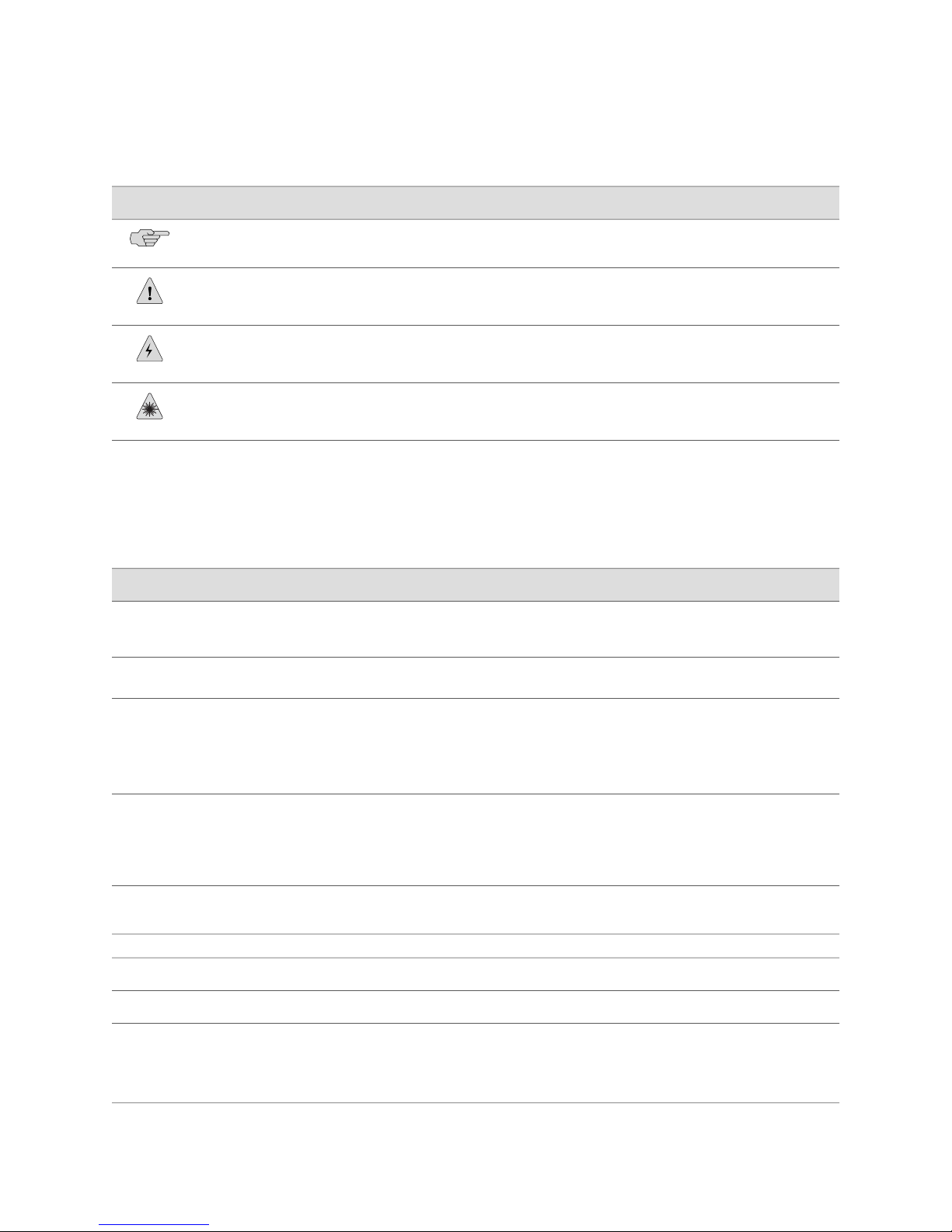
Table 1: Notice Icons
Table 2 on page xxiv defines text and syntax conventions that we use throughout the
E Series and JUNOSe documentation.
DescriptionMeaningIcon
Indicates important features or instructions.Informational note
Indicates a situation that might result in loss of data or hardware damage.Caution
Alerts you to the risk of personal injury or death.Warning
Alerts you to the risk of personal injury from a laser.Laser warning
Table 2: Text and Syntax Conventions
Represents commands and keywords in text.Bold text like this
Bold text like this
Fixed-width text like this
Represents text that the user must type.
Represents information as displayed on your
terminal’s screen.
Italic text like this
Emphasizes words.
■
Identifies variables.
■
Identifies chapter, appendix, and book
■
names.
Plus sign (+) linking key names
keys simultaneously.
Syntax Conventions in the Command Reference Guide
ExamplesDescriptionConvention
Issue the clock source command.
■
Specify the keyword exp-msg.
■
host1(config)#traffic class low-loss1
host1#show ip ospf 2
Routing Process OSPF 2 with Router
ID 5.5.0.250
Router is an Area Border Router
(ABR)
There are two levels of access: user and
■
privileged.
clusterId, ipAddress.
■
Appendix A, System Specifications
■
Press Ctrl + b.Indicates that you must press two or more
terminal lengthRepresents keywords.Plain text like this
| (pipe symbol)
xxiv ■ E Series and JUNOSe Text and Syntax Conventions
mask, accessListNameRepresents variables.Italic text like this
diagnostic | lineRepresents a choice to select one keyword
or variable to the left or to the right of this
symbol. (The keyword or variable can be
either optional or required.)
Page 25

Table 2: Text and Syntax Conventions (continued)
About the Documentation
ExamplesDescriptionConvention
[ internal | external ]Represent optional keywords or variables.[ ] (brackets)
[ ]* (brackets and asterisk)
that can be entered more than once.
Represent required keywords or variables.{ } (braces)
Obtaining Documentation
To obtain the most current version of all Juniper Networks technical documentation,
see the Technical Documentation page on the Juniper Networks Web site at
http://www.juniper.net/.
To download complete sets of technical documentation to create your own
documentation CD-ROMs or DVD-ROMs, see the Offline Documentation page at
http://www.juniper.net/techpubs/resources/cdrom.html
Copies of the Management Information Bases (MIBs) for a particular software release
are available for download in the software image bundle from the Juniper Networks
Web site athttp://www.juniper.net/.
Documentation Feedback
[ level1 | level2 | l1 ]*Represent optional keywords or variables
{ permit | deny } { in | out }
{ clusterId | ipAddress }
We encourage you to provide feedback, comments, and suggestions so that we can
improve the documentation to better meet your needs. Send your comments to
techpubs-comments@juniper.net, or fill out the documentation feedback form at
https://www.juniper.net/cgi-bin/docbugreport/. If you are using e-mail, be sure to include
the following information with your comments:
■ Document or topic name
■ URL or page number
■ Software release version
Requesting Technical Support
Technical product support is available through the Juniper Networks Technical
Assistance Center (JTAC). If you are a customer with an active J-Care or JNASC support
contract, or are covered under warranty, and need post-sales technical support, you
can access our tools and resources online or open a case with JTAC.
■ JTAC policies—For a complete understanding of our JTAC procedures and policies,
review the JTAC User Guide located at
http://www.juniper.net/customers/support/downloads/7100059-EN.pdf .
Obtaining Documentation ■ xxv
Page 26

JUNOSe 11.1.x Policy Management Configuration Guide
■ Product warranties—For product warranty information, visit
http://www.juniper.net/support/warranty/ .
■ JTAC hours of operation—The JTAC centers have resources available 24 hours a
day, 7 days a week, 365 days a year.
Self-Help Online Tools and Resources
For quick and easy problem resolution, Juniper Networks has designed an online
self-service portal called the Customer Support Center (CSC) that provides you with
the following features:
■
Find CSC offerings: http://www.juniper.net/customers/support/
■
Search for known bugs: http://www2.juniper.net/kb/
■
Find product documentation: http://www.juniper.net/techpubs/
■ Find solutions and answer questions using our Knowledge Base:
http://kb.juniper.net/
■ Download the latest versions of software and review release notes:
http://www.juniper.net/customers/csc/software/
■ Search technical bulletins for relevant hardware and software notifications:
https://www.juniper.net/alerts/
■ Join and participate in the Juniper Networks Community Forum:
http://www.juniper.net/company/communities/
■
Open a case online in the CSC Case Management tool: http://www.juniper.net/cm/
To verify service entitlement by product serial number, use our Serial Number
Entitlement (SNE) Tool: https://tools.juniper.net/SerialNumberEntitlementSearch/
Opening a Case with JTAC
You can open a case with JTAC on the Web or by telephone.
■
Use the Case Management tool in the CSC at http://www.juniper.net/cm/ .
■ Call 1-888-314-JTAC (1-888-314-5822 toll-free in the USA, Canada, and Mexico).
For international or direct-dial options in countries without toll-free numbers, see
http://www.juniper.net/support/requesting support.html .
xxvi ■ Requesting Technical Support
Page 27

Part 1
Policy Management
■ Managing Policies on the E Series Router on page 3
■ Creating Classifier Control Lists for Policies on page 7
■ Creating Policy Lists on page 17
■ Creating Classifier Groups and Policy Rules on page 31
■ Creating Rate-Limit Profiles on page 61
■ Merging Policies on page 101
■ Creating Hierarchical Policies for Interface Groups on page 129
■ Policy Resources on page 159
■ Monitoring Policy Management on page 181
Policy Management ■ 1
Page 28

JUNOSe 11.1.x Policy Management Configuration Guide
2 ■ Policy Management
Page 29

Chapter 1
Managing Policies on the E Series Router
This chapter discusses the following topics:
■ Policy Management Overview on page 3
■ Description of a Policy on page 5
■ Policy Platform Considerations on page 5
■ Policy References on page 6
■ Policy Management Configuration Tasks on page 6
Policy Management Overview
This chapter introduces policy-based routing management on E Series routers. Policy
management enables you to configure, manage, and monitor policies that selectively
cause packets to take different paths without requiring a routing table lookup. The
JUNOSe software’s packet-mirroring feature uses secure policies.
Policy management enables network service providers to configure services that
customize the treatment of individual packet flows received on a subscriber’s
interface. The main tool for implementing policy management is a policy list. A policy
list is a set of rules, each of which specifies a policy action. A rule is a policy action
optionally combined with a classification.
Packets are sorted at ingress or egress into packet flows based on attributes defined
in classifier control lists (CLACLs). You can apply policy lists to packets arriving and
leaving an interface. You can use policy management on ATM, Frame Relay, generic
routing encapsulation (GRE), IP, IPv6, Layer 2 Tunneling Protocol (L2TP), Multiprotocol
Label Switching (MPLS), and virtual local area network (VLAN) traffic.
Policy management provides:
■ Policy routing—Predefines a classified packet flow to a destination port or IP
address. The router does not perform a routing table lookup on the packet. This
provides superior performance for real-time applications.
■ Bandwidth management—Rate-limits a classified packet flow at ingress to enforce
ingress data rates below the physical line rate of a port, A rate-limit profile with
a policy rate-limit profile rule provides this capability. You can construct policies
to provide rate limiting for individual packet flows or for the aggregate of multiple
packet flows. Juniper Networks E Series Broadband Services Router rate limits
are calculated based on the layer 2 packet size. To configure rate limiting, you
first create a rate-limit profile, which is a set of bandwidth attributes and
Policy Management Overview ■ 3
Page 30

JUNOSe 11.1.x Policy Management Configuration Guide
associated actions. You next create a policy list with a rule that has rate limit as
the action and associate a rate-limit profile with this rule. You can configure
rate-limit profiles to provide a variety of services, including tiered bandwidth
service where traffic conforming to configured bandwidth levels is treated
differently than traffic that exceeds the configured values, and a hard-limit service
where a fixed bandwidth limit is applied to a traffic flow. Finally, you can
configure rate-limit profiles to provide a TCP-friendly rate-limiting service that
works in conjunction with TCP’s native flow-control functionality.
■ Security—Provides a level of network security by using policy rules that selectively
forward or filter packet flows. You can use a filter rule to stop a denial-of-service
attack. You can use secure policies to mirror packets and send them to an
analyzer.
■ RADIUS policy support—Enables you to create and attach a policy to an interface
through RADIUS.
■ Packet tagging—Enables the traffic-class rule in policies to tag a packet flow so
that the Quality of Service (QoS) application can provide traffic-class queuing.
Policies can perform both in-band and out-of-band packet tagging.
■ Packet forwarding—Allows forwarding of packets in a packet flow.
■ Packet filtering—Drops packets in a packet flow.
■ Packet mirroring—Uses secure policies to mirror packets and send them to an
analyzer.
■ Packet logging—Logs packets in a packet flow.
Policy management gives you the CLI tools to build databases, which can then be
drawn from to implement a policy. Each database contains global traffic specifications.
When building a policy, you specify input from one or more of these databases and
then attach the policy to an interface. By combining the information from the various
databases into policies, you can deploy a wide variety of services.
NOTE: When applying policies to interfaces that are managed by the SRC, avoid
using any other policy management tools, such as CLI, RADIUS, CoA, or Service
Manager. SRC is not compatible with other types of policy management tools. When
policies are applied to the interface before SRC management begins, such as at
access-accept time, these policies are properly replaced. However, if other policy
managers change existing policies while SRC management is active, problems can
occur. The precedence of each source when modifying configurations is:
■ If you have a pre-configured policy through CLI as part of subscriber PVC/VLAN
provisioning, SRC overwrites the policy when the SRC manages the interface
■ If you have a policy in the Access-Accept, SRC overwrites the policy when the
SRC manages the interface
4 ■ Policy Management Overview
Page 31

Description of a Policy
A policy is a condition and an action that is attached to an interface. The condition
and action cause the router to handle the packets passing through the interface in a
certain way. A policy can be attached to IP interfaces and certain layer 2 interfaces
such as Frame Relay, L2TP, MPLS, and VLAN interfaces. The policies do not need to
be the same in both directions.
Packets are sorted at ingress or egress into packet flows based on attributes defined
in classifier control lists. Policy lists contain rules that associate actions with these
CLACLs. A rule is a policy action optionally combined with a classification.
When packets arrive on an interface, you can have a policy evaluate a condition
before the normal route lookup; this kind of policy is known as an input policy. You
can also have conditions evaluated after a route lookup; this kind of policy is known
as a secondary input policy. You can use secondary input policies to defeat
denial-of-service attacks directed at a router’s local interface or to protect a router
from being overwhelmed by legitimate local traffic. If you have a policy applied to
packets before they leave an interface, this is known as an output policy.
Chapter 1: Managing Policies on the E Series Router
Classification is the process of taking a single data stream in and sorting it into
multiple output substreams. The classifier engine on an E Series router is a
combination of PowerPC processors, working with a Field Programmable Gate Array
(FPGA) for a hardware assist.
In the Differentiated Services (DiffServ) architecture, two basic types of classifiers
exist. The first classifier type is a multifield (MF) classifier, which examines multiple
fields in the IP datagram header to determine the service class to which a packet
belongs. The second type of classifier is a behavior aggregate (BA) classifier, which
examines a single field in an IP datagram header and assigns the packet to a service
class based on what it finds.
There are two categories of hardware classifiers, depending on the type of line module
being used. ES2 4G LM, ES2 10G Uplink LM, ES2 10G LM, OC48/STM16, GE-2, and
GE-HDE line modules support content-addressable memory (CAM) hardware
classifiers—all other line modules support FPGA hardware classifiers.
The maximum number of policies that you can attach to interfaces on an E Series
router depends on the classifier entries that make up the policy and the number of
attachment resources available on the interface. JUNOSe software allocates interface
attachment resources when you attach policies to interfaces. E Series routers support
software and hardware classifiers. A policy can be made up of any combination of
software and hardware classifiers.
Policy Platform Considerations
Policy services are supported on all E Series routers.
For information about the modules supported on E Series routers:
Description of a Policy ■ 5
Page 32

JUNOSe 11.1.x Policy Management Configuration Guide
■ See the ERX Module Guide for modules supported on ERX7xx models, ERX14xx
models, and the Juniper Networks ERX310 Broadband Services Router.
■ See the E120 and E320 Module Guide for modules supported on the Juniper
Networks E120 and E320 Broadband Services Routers.
Policy References
For more information about policy management, see the following resources:
■ RFC 2474—Definition of the Differentiated Services Field (DS Field) in the IPv4
and IPv6 Headers (December 1998)
■ RFC 2475—An Architecture for Differentiated Services (December 1998)
■ RFC 2697—A Single Rate Three Color Marker (September 1999)
■ RFC 2698—A Two Rate Three Color Marker (September 1999)
■ RFC 3198—Terminology for Policy-Based Management (November 2001)
Policy Management Configuration Tasks
Perform the required tasks and also any optional tasks that you need for your policy
management configuration:
1. Create a CLACL (optional).
See “Classifier Control Lists Overview” on page 7
2. Create a rate-limit profile (optional).
See “Creating Rate-Limit Profiles” on page 77
3. Create a policy list.
See “Policy Lists Overview” on page 17
4. Create a classifier group.
See “Classifier Groups and Policy Rules Overview” on page 31
5. Create one or more policy rules within the classifier group.
See “Rate Limits for Interfaces Overview” on page 62
6. Apply a policy list to an interface or profile.
See “Classifier Groups and Policy Rules Overview” on page 31
6 ■ Policy References
Page 33

Chapter 2
Creating Classifier Control Lists for
Policies
This chapter provides information for configuring policy-based routing management
on E Series routers. See the E120 and E320 Module Guide for modules supported on
the E120 and E320 Broadband Services Routers. The chapter discusses the following
topics:
■ Classifier Control Lists Overview on page 7
■ Creating or Modifying Classifier Control Lists for ATM Policy Lists on page 10
■ Creating or Modifying Classifier Control Lists for Frame-Relay Policy
Lists on page 10
■ Creating or Modifying Classifier Control Lists for GRE Tunnel Policy
Lists on page 10
■ Creating or Modifying Classifier Control Lists for IP Policy Lists on page 11
■ Creating or Modifying Classifier Control Lists for IPv6 Policy Lists on page 14
■ Creating or Modifying Classifier Control Lists for L2TP Policy Lists on page 14
■ Creating or Modifying Classifier Control Lists for MPLS Policy Lists on page 14
■ Creating or Modifying Classifier Control Lists for VLAN Policy Lists on page 15
Classifier Control Lists Overview
Classifier control lists (CLACLs) specify the criteria by which the router defines a
packet flow. Table 3 on page 7 lists the criteria that you can use to create CLACLs
for different types of traffic flows.
Table 3: CLACL Criteria
ATM
CriteriaType of CLACL
CLP
■
Color
■
Traffic class
■
User packet class
■
Classifier Control Lists Overview ■ 7
Page 34

JUNOSe 11.1.x Policy Management Configuration Guide
Table 3: CLACL Criteria (continued)
CriteriaType of CLACL
Frame Relay
GRE
IP
Color
■
Mark discard eligibility (DE) bit
■
Traffic class
■
User packet class
■
Color
■
Traffic class
■
Type-of-service (ToS) byte
■
User packet class
■
Color
■
Destination IP address
■
Destination port
■
Destination route class
■
Internet Control Message Protocol (ICMP)
■
Internet Gateway Management Protocol (IGMP)
■
IP flags
■
IP fragmentation offset
■
Locally destined traffic
■
Protocol
■
Source IP address
■
Source port
■
Source route class
■
Transmission Control Protocol (TCP)
■
Traffic class
■
Type-of-service (ToS) byte
■
User Datagram Protocol (UDP)
■
User packet class
■
8 ■ Classifier Control Lists Overview
Page 35

Table 3: CLACL Criteria (continued)
CriteriaType of CLACL
Chapter 2: Creating Classifier Control Lists for Policies
IPv6
L2TP
MPLS
Color
■
Destination IPv6 address
■
Destination port
■
Destination route class
■
Internet Control Message Protocol version 6 (ICMPv6)
■
IPv6 traffic class
■
Locally destined traffic
■
Multicast Listener Discovery (MLD)
■
Next header
■
Source IPv6 address
■
Source port
■
Source route class
■
Traffic class
■
Transmission Control Protocol (TCP)
■
User Datagram Protocol (UDP)
■
User packet class
■
Color
■
Traffic class
■
User packet class
■
Color
■
Mark experimental (EXP) bit
■
Traffic class
■
User packet class
■
VLAN
Color
■
Traffic class
■
User packet class
■
User priority
■
You configure CLACLs with a name and then values to match in the IP datagram
header. A CLACL does not include an action: actions take place when a match is
included in a policy list.
NOTE: Do not use the asterisk (*) for the name of a classifier list. The asterisk is used
as a wildcard for the classifier-group command.
If you do not specify one of the frame-relay, gre-tunnel, ip, ipv6, l2tp, mpls, or
vlan keywords, the router creates an IP classifier list. This version of the command
has been deprecated and may be removed in a future release.
Classifier Control Lists Overview ■ 9
Page 36

JUNOSe 11.1.x Policy Management Configuration Guide
Related Topics For information about the hardware and software CLACLs that are supported
■
for each interface type, see Policy Resources Overview on page 159.
■ For information about monitoring Classifier Lists, see Monitoring Policy
Management Overview on page 181.
Creating or Modifying Classifier Control Lists for ATM Policy Lists
You can create or modify a classifier control list that can be used only in ATM policy
lists.
■ Issue the atm classifier-list command:
host1(config)#atm classifier-list atmclassifier color red user-packet-class 10
clp 1
Related Topics ■ atm classifier-list
Creating or Modifying Classifier Control Lists for Frame-Relay Policy Lists
You can create or modify a classifier control list that can be used only in Frame Relay
policy lists.
■ Issue the frame-relay classifier-list command.;
host1(config)#frame-relay classifier-list frclassifier color red user-packet-class
10 de-bit 1
Related Topics ■ frame-relay classifier-list
Creating or Modifying Classifier Control Lists for GRE Tunnel Policy Lists
You can create or modify a classifier control list that can be used only in GRE tunnel
policy lists.
■ Issue the gre-tunnel classifier-list command:
host1(config)#gre-tunnel classifier-list greClassifier50 color yellow
user-packet-class 7 dsfield 40
10 ■ Creating or Modifying Classifier Control Lists for ATM Policy Lists
Page 37

Chapter 2: Creating Classifier Control Lists for Policies
Related Topics ■ gre-tunnel classifier-list
Creating or Modifying Classifier Control Lists for IP Policy Lists
Tasks to create or modify classifier control lists for IP policy lists:
■ Creating Classifier Control List for Only IP Policy Lists on page 11
■ Setting Up an IP Classifier Control List to Accept Traffic from All
Sources on page 11
■ Classifying IP Traffic Based on Source and Destination Addresses on page 11
■ Using IP Classifier Control Lists to Match Route Class Values on page 12
■ Creating IP Classifier Control Lists for TCP and UDP Ports on page 12
■ Creating an IP Classifier Control List That Matches the ToS Byte on page 13
■ Creating an IP Classifier Control List That Filters ICMP Echo Requests on page 13
■ Creating IP Classifier Control Lists That Use TCP or IP Flags on page 13
■ Creating IP Classifier Control Lists That Match the IP Fragmentation
Offset on page 13
Creating Classifier Control List for Only IP Policy Lists
You can create or modify a classifier control list that can be used only in IP policy
lists.The behavior of multiple-element classifier-list classification is the logical OR of
the elements in the CLACL.
■ Issue the ip classifier-list command to match all packets that have a source IP
address of 192.168.30.100 or have a destination IP address of 192.168.30.200:
host1(config)#ip classifier-list boston5 ip host 192.168.30.100 any
host1(config)#ip classifier-list boston5 ip any host 192.168.30.200
Setting Up an IP Classifier Control List to Accept Traffic from All Sources
You can set up a CLACL to accept IP traffic from all source addresses on the subnet.
■ Issue the ip classifier-list command:
host1(config)#ip classifier-list XYZCorpPermit ip 192.168.0.0 0.0.255.255 any
Classifying IP Traffic Based on Source and Destination Addresses
You can classify traffic based on source and destination addresses, You can specify
the address as a host address, or a subnet with a wildcard. If you specify the address
as a subnet, the mask, in binary notation, must be a series of contiguous zeros,
followed by a series of contiguous ones. The any keyword is the address wildcard,
matching traffic for any address.
Creating or Modifying Classifier Control Lists for IP Policy Lists ■ 11
Page 38

JUNOSe 11.1.x Policy Management Configuration Guide
■ Issue the ip classifier-list command to classify traffic on any source or destination
address:
host1(config)#ip classifier-list YourListName ip any any
host1(config)#ip classifier-list YourListName ip host 10.10.10.10 any
host1(config)#ip classifier-list YourListName ip 10.10.0.0 0.0.255.255 host
10.10.10.2
Using IP Classifier Control Lists to Match Route Class Values
You can set up classifier control lists to match route-class values. In this example,
svale20 matches the source address lookup route-class value of 1, svale30 matches
the destination address lookup route-class value of 1 and a ToS byte value of 10,
svale40 matches the source address lookup route-class value of 1 and the packets
destined to a local interface, and west20 matches the source address lookup
route-class value of 1 and packets that are not destined for a local interface (packets
destined for remote interfaces).
■ Issue the ip classifier-list command:
host1(config)#ip classifier-list svale20 source-route-class 1 ip any any
host1(config)#ip classifier-list svale30 destination-route-class 1 ip any any
tos 10
host1(config)#ip classifier-list svale40 source-route-class 1 local true ip any any
host1(config)#ip classifier-list west25 source-route-class 1 local false ip any
any
Creating IP Classifier Control Lists for TCP and UDP Ports
You can specify a single TCP or UDP port or a range of ports, where packets are
matched with source address 198.168.30.100 and UDP source port numbers in the
range 1–10.
■ Issue the ip classifier-list command to create a CLACL on a UDP host:
host1(config)#ip classifier-list YourListName udp host 192.168.30.100 range
1 10 any
To create a CLACL that matches all traffic on UDP source ports greater than 100:
host1(config)#ip classifier-list XYZCorpUdp udp any gt 100 172.17.2.1
0.0.255.255
To match a non-TCP packet originating from IP address 172.28.100.52:
To specify a single TCP or UDP port or range of ports, an ICMP code and optional
type, or an IGMP type, which matches packets with source address
198.168.30.100 and ICMP type 2 and code 10:
12 ■ Using IP Classifier Control Lists to Match Route Class Values
host1(config)#ip classifier-list YourListName not tcp host 172.28.100.52 any
host1(config)#ip classifier-list YourListName icmp host 192.168.30.100 any 2
10
Page 39

Chapter 2: Creating Classifier Control Lists for Policies
Creating an IP Classifier Control List That Matches the ToS Byte
You can create an IP CLACL that matches the ToS byte in the IP header.
■ Issue the ip classifier-list command using the tos keyword.
host1(config)#ip classifier-list tos128 ip any any tos 128
host1(config)#ip classifier-list low-drop-prec ip any any dsfield 10
host1(config)#ip classifier-list priority ip any any precedence 1
Creating an IP Classifier Control List That Filters ICMP Echo Requests
You can create a CLACL that filters all ICMP echo requests headed toward an access
link under a denial-of-service attack.
■ Issue the ip classifier-list command:
host1(config)#ip classifier-list XYZCorpIcmpEchoReqs icmp any any 8 0
host1(config)#ip classifier-list XYZCorpIgmpType1 igmp any any 1
Creating IP Classifier Control Lists That Use TCP or IP Flags
You can create CLACLs that use TCP or IP flags. For both IP flags and TCP flags, if
you specify only a single flag, the logical equation does not require quotation marks.
■ Issue the ip classifier-list command with the tcp-flags keyword and a logical
equation (a quotation-enclosed string using ! for NOT, & for AND) to match one
or more of the ack, fin, psh, rst, syn, or urg TCP flags:
host1(config)#ip classifier-list telnetConnects tcp 192.168.10.0 0.0.0.255 host
10.10.10.10 eq 23 tcp-flags "syn & !ack"
■ Issue the ip classifier-list command with the ip-flags keyword and a logical
equation (a quotation-enclosed string using ! for NOT, & for AND) to match one
or more of the dont-fragment, more-fragments,, or reserved IP flags:
host1(config)#ip classifier-list dontFragment ip any any ip-flags "dont-fragment"
Creating IP Classifier Control Lists That Match the IP Fragmentation Offset
You can create CLACLs that match the IP fragmentation offset.
■ Issue the ip classifier-list command with the ip-frag-offset keyword and the eq
or gt operator to match an IP fragmentation offset equal to 0, 1, or greater
than 1:
host1(config)#ip classifier-list fragOffsetAttack ip any host 10.10.10.10
ip-frag-offset eq 1
host1(config)#ip policy-list dosProtect
host1(config-policy-list)#filter classifier-group fragOffsetAttack
host1(config-policy-list)#forward
Creating an IP Classifier Control List That Matches the ToS Byte ■ 13
Page 40

JUNOSe 11.1.x Policy Management Configuration Guide
Creating or Modifying Classifier Control Lists for IPv6 Policy Lists
You can create or modify a classifier control list that can be used only in IPv6 policy
lists.
■ Issue the ipv6 classifier-list command:
host1(config)#ipv6 classifier-list ipv6classifier color red user-packet-class 5
tcfield 10
host1(config)#ipv6 classifier-list YourListName udp destination-port eq 75
host1(config)#ipv6 classifier-list telnetConnects tcp destination-port eq 23
tcp-flags "syn & !ack"
host1(config)#ipv6 classifier-list listname icmpv6 icmp-type 3 icmp-code 6
host1(config)#ipv6 classifier-list svale20 source-route-class 1
host1(config)#ipv6 classifier-list svale30 destination-route-class 1 tcfield 10
host1(config)#ipv6 classifier-list svale40 source-route-class 1 local true
host1(config)#ipv6 classifier-list west25 source-route-class 1 local false
host1(config)#ipv6 classifier-list YourClaclList source-host 2001:db8:1::8001
destination-address 2001:db8:3::/48
Related Topics ■ ipv6 classifier-list
Creating or Modifying Classifier Control Lists for L2TP Policy Lists
You can create or modify a classifier control list that can be used only in L2TP policy
lists.
■ Issue the l2tp classifier-list command:
host1(config)#l2tp classifier-list l2tpclassifier color red user-packet-class 7
Related Topics ■ l2tp classifier-list
Creating or Modifying Classifier Control Lists for MPLS Policy Lists
You can create or modify a classifier control list that can be used only in MPLS policy
lists.
■ Issue the mpls classifier-list command:
host1(config)#mpls classifier-list mplsClass user-packet-class 10 exp-bits 3
exp-mask 5
14 ■ Creating or Modifying Classifier Control Lists for IPv6 Policy Lists
Page 41

Chapter 2: Creating Classifier Control Lists for Policies
Related Topics ■ mpls classifier-list
Creating or Modifying Classifier Control Lists for VLAN Policy Lists
You can create or modify a classifier control list that can be used only in VLAN policy
lists.
■ Issue the vlan classifier-list command:
host1(config)#vlan classifier-list lowLatencyLowDrop user-priority 7
host1(config)#vlan classifier-list lowLatencyLowDrop user-priority 6
host1(config)#vlan classifier-list lowLatency user-priority 5
host1(config)#vlan classifier-list excellentEffort user-priority 4
host1(config)#vlan classifier-list bestEffort user-priority 3
host1(config)#vlan classifier-list bestEffort user-priority 2
host1(config)#vlan classifier-list bestEffort user-priority 1
host1(config)#vlan classifier-list bestEffort user-priority 0
NOTE: You cannot configure classifier control lists (CLACLs) for policy lists to be
attached to VLAN interfaces, without specifying the criteria by which the router
defines a packet flow. Although the carriage return, <cr>, option is displayed when
you type a question mark (?) after entering the vlan classifier list classiferName
command without defining any other keyword or CLACL criterion, an error message
is displayed when you press Enter to configure the VLAN CLACL with only the name.
You must specify at least one criterion for the VLAN CLACL to be successfully
configured.
Related Topics ■ vlan classifier-list
Creating or Modifying Classifier Control Lists for VLAN Policy Lists ■ 15
Page 42

JUNOSe 11.1.x Policy Management Configuration Guide
16 ■ Creating or Modifying Classifier Control Lists for VLAN Policy Lists
Page 43

Chapter 3
Creating Policy Lists
This chapter provides information for configuring policy lists on E Series Broadband
Services Routers. See the E120 and E320 Module Guide for modules supported on the
E120 and E320 Broadband Services Routers. The chapter discusses the following
topics:
■ Policy Lists Overview on page 17
■ Creating Policy Lists for ATM on page 19
■ Creating Policy Lists for Frame Relay on page 21
■ Creating Policy Lists for GRE Tunnels on page 23
■ Creating Policy Lists for IP on page 24
■ Creating Policy Lists for IPv6 on page 25
■ Creating Policy Lists for L2TP on page 27
■ Creating Policy Lists for MPLS on page 27
■ Creating Policy Lists for VLANs on page 28
Policy Lists Overview
You create a policy rule by specifying a policy action within a classifier group that
references a CLACL. These rules become part of a policy list that you can attach to
an interface as either an input policy, secondary-input policy, or output policy. The
router applies the rules in the attached policy list to the packets traversing that
interface.
You can apply policy lists to packets:
■ Arriving at an interface (input policy); on IP and IPv6 interfaces the packets arrive
■ Arriving at the interface, but after route lookup (secondary input policy);
■ Leaving an interface (output policy)
Figure 1 on page 18 shows how a sample IP policy list is constructed.
before route lookup
secondary input policies are supported only on IP and IPv6 interfaces
Policy Lists Overview ■ 17
Page 44

JUNOSe 11.1.x Policy Management Configuration Guide
Figure 1: Constructing an IP Policy List
Related Topics Policy Lists Overview on page 17■
You can create a policy list with an unlimited number of classifier groups, each
containing an unlimited number of rules. These rules can reference up to 512 classifier
entries.
If you enter a policy-list command and then enter exit, the router creates a policy
list with no rules. If the router does not find any rules in a policy, it inserts a default
filter rule. Attaching this policy list to an interface filters all packets on that interface.
NOTE: If you do not specify one of the frame-relay, gre-tunnel, ip, ipv6, l2tp, mpls,
or vlan keywords, the router creates an IP policy list. This version of the command
has been deprecated and may be removed in a future release.
You can create policy lists for ATM, Frame Relay, IP, IPv6, GRE tunnels, L2TP, MPLS,
and VLANs.
NOTE: Commands that you issue in Policy Configuration mode do not take effect
until you exit from that mode.
■ Monitoring Policy Management Overview on page 181
18 ■ Policy Lists Overview
Page 45

Creating Policy Lists for ATM
In the following example, you create two policies: one for CBR traffic and one for
UBR traffic. One policy is attached to an interface that contains CBR traffic and the
other to an interface that contains UBR traffic.
1. Create a CBR policy list.
host1(config)#atm policy-list polCbr
host1(config-policy-list)#
2. Create the classification group and assign a strict priority traffic class and color
green.
host1(config-policy-list)#classifier-group *
host1(config-policy-list-classifier-group)#traffic-class strict-priority
host1(config-policy-list-classifier-group)#color green
Chapter 3: Creating Policy Lists
3. Exit Policy List Configuration mode to save the configuration.
host1(config-policy-list-classifier-group)#exit
host1(config-policy-list)#exit
host1(config)#
4. Create a UBR policy that maps to the strict best-effort traffic class and color red.
host1(config)#atm policy-list polUbr
host1(config-policy-list)#classifier-group *
host1(config-policy-list-classifier-group)#traffic-class best-effort
host1(config-policy-list-classifier-group)#color red
5. Exit Policy List Configuration mode to save the configuration.
host1(config-policy-list-classifier-group)#exit
host1(config-policy-list)#exit
host1(config)#
6. Attach the policies to ATM subinterfaces.
host1(config)#interface atm 0/0.100
host1(config-if)#atm policy input polUbr statistics enabled
host1(config-if)#exit
host1(config)#interface atm 0/0.101
host1(config-if)#atm policy input polCbr statistics enabled
host1(config-if)#exit
7. Display the policy lists.
host1#show atm subinterface atm 0/0.100
Circuit Interface
Interface ATM-Prot VCD VPI VCI Type Encap MTU Status Type
----------- -------- --- --- --- ------- ----- ---- ------ --------ATM 0/0.100 RFC-1483 100 0 100 PVC SNAP 9180 up Static
Creating Policy Lists for ATM ■ 19
Page 46

JUNOSe 11.1.x Policy Management Configuration Guide
Auto configure status : static
Auto configure interface(s) : none
Detected 1483 encapsulation : none
Detected dynamic interface : none
Interface types in lockout : none
Assigned profile (IP) : none assigned
Assigned profile (BridgedEnet): none assigned
Assigned profile (PPP) : none assigned
Assigned profile (PPPoE) : none assigned
Assigned profile (any) : none assigned
SNMP trap link-status: disabled
InPackets: 0
InBytes: 0
OutPackets: 0
OutBytes: 0
InErrors: 0
OutErrors: 0
InPacketDiscards: 0
InPacketsUnknownProtocol: 0
OutDiscards: 0
ATM policy input polUbr
Statistics are disabled
1 interface(s) found
host1#show atm subinterface atm 0/0.101
Circuit Interface
Interface ATM-Prot VCD VPI VCI Type Encap MTU Status Type
----------- -------- --- --- --- ------- ----- ---- ------ --------ATM 0/0.101 RFC-1483 101 0 101 PVC SNAP 9180 up Static
Auto configure status : static
Auto configure interface(s) : none
Detected 1483 encapsulation : none
Detected dynamic interface : none
Interface types in lockout : none
Assigned profile (IP) : none assigned
Assigned profile (BridgedEnet): none assigned
Assigned profile (PPP) : none assigned
Assigned profile (PPPoE) : none assigned
Assigned profile (any) : none assigned
SNMP trap link-status: disabled
InPackets: 0
InBytes: 0
OutPackets: 0
OutBytes: 0
InErrors: 0
OutErrors: 0
InPacketDiscards: 0
InPacketsUnknownProtocol: 0
OutDiscards: 0
ATM policy input polCbr
classifier-group *
3096 packets, 377678 bytes
traffic-class best-effort
20 ■ Creating Policy Lists for ATM
Page 47

color green
1 interface(s) found
Related Topics ■ atm policy-list
Creating Policy Lists for Frame Relay
The following example creates a Frame Relay policy that on egress marks the DE bit
to 1, and on ingress colors frames with a DE bit of 1 as red.
1. Create the policy list used to mark egress traffic, then create the classifier group
for packets conforming to CLACL frMatchDeSet. Add a rule that marks the DE
bit as 1.
host1(config)#frame-relay policy-list frOutputPolicy
host1(config-policy-list)#classifier-group frMatchDeSet
host1(config-policy-list-classifier-group)#mark-de 1
host1(config-policy-list-classifier-group)#exit
host1(config-policy-list)#exit
Chapter 3: Creating Policy Lists
2. Create the policy list used for the ingress traffic. and create the classifier group
conforming to CLACL frMatchDeSet. Add a rule that colors the ingress traffic.
host1(config)#frame-relay policy-list frInputPolicy
host1(config-policy-list)#classifier-group frGroupA
host1(config-policy-list-classifier-group)#color red
host1(config-policy-list-classifier-group)#exit
host1(config-policy-list)#exit
3. Apply the policy lists.
host1(config)#interface serial 5/0:1/1.1
host1(config-subif)#frame-relay policy output frOutputPolicy statistics enabled
host1(config-subif)#ip address 10.0.0.1 255.255.255.0
host1(config-subif)#exit
host1(config)#interface serial 5/1:1/1.1
host1(config-subif)#frame-relay policy input frInputPolicy statistics enabled
host1(config-subif)#exit
4. Display interface information to view the applied policies.
host1#show frame-relay subinterface
Frame relay sub-interface SERIAL5/0:1/1.1, status is up
Number of sub-interface down transitions is 0
Time since last status change 03:04:59
No baseline has been set
In bytes: 660 Out bytes: 660
In frames: 5 Out frames: 5
In errors: 0 Out errors: 0
In discards: 0 Out discards: 0
In unknown protos: 0
Frame relay policy output frOutputPolicy
Creating Policy Lists for Frame Relay ■ 21
Page 48

JUNOSe 11.1.x Policy Management Configuration Guide
classifier-group frGroupA entry 1
5 packets, 640 bytes
mark-de 1
Frame relay sub-interface SERIAL5/1:1/1.1, status is up
Number of sub-interface down transitions is 0
Time since last status change 03:05:09
No baseline has been set
In bytes: 660 Out bytes: 660
In frames: 5 Out frames: 5
In errors: 0 Out errors: 0
In discards: 0 Out discards: 0
In unknown protos: 0
Frame relay policy input frInputPolicy
classifier-group frMatchDeSet entry 1
5 packets, 660 bytes
color red
5. Display the classifier list.
host1#show classifier-list detailed
Classifier Control List Table
---------- ------- ---- ----Frame relay Classifier Control List frMatchDeSet
Reference count: 1
Entry count: 1
Classifier-List frMatchDeSet Entry 1
DE Bit: 1
6. Display the policy lists.
host1#show policy-list
Policy Table
------ -----
Frame relay Policy frOutputPolicy
Administrative state: enable
Reference count: 0
Classifier control list: frMatchDeSet, precedence 100
mark-de 1
Frame relay Policy frInputPolicy
Administrative state: enable
Reference count: 0
Classifier control list: frGroupA, precedence 100
color red
22 ■ Creating Policy Lists for Frame Relay
Page 49

Related Topics ■ frame-relay policy-list
Creating Policy Lists for GRE Tunnels
The following example creates a GRE tunnel policy list named routeGre50. For
information about creating the CLACL used in this example, see the previous sections.
1. Create the policy list routeGre50.
host1(config)#gre-tunnel policy-list routeGre50
2. Create the classification group for the CLACL named gre8 and assign a precedence
of 150 to it.
host1(config-policy-list)#classifier-group gre8 precedence 150
host1(config-policy-list-classifier-group)#
Chapter 3: Creating Policy Lists
3. Add two rules for traffic based on the CLACL named gre8: one rule to color
packets as red, and a second rule that specifies the ToS DS field value to be
assigned to the packets.
host1(config-policy-list-classifier-group)#color red
host1(config-policy-list-classifier-group)#mark dsfield 20
host1(config-policy-list-classifier-group)#
4. Exit Policy List Configuration mode to save the configuration.
host1(config-policy-list-classifier-group)#exit
host1(config-policy-list)#exit
host1(config)#
5. Display the policy list.
host1#show policy-list routeGre50
Policy Table
------ ----GRE Tunnel Policy routeGre50
Administrative state: enable
Reference count: 0
Classifier control list: gre8, precedence 150
color red
mark dsfield 20
Creating Policy Lists for GRE Tunnels ■ 23
Page 50

JUNOSe 11.1.x Policy Management Configuration Guide
Related Topics ■ gre-tunnel policy-list
Creating Policy Lists for IP
The following example creates an IP policy list named routeForABCCorp. For
information about creating the CLACLs and rate-limit profile used in this example,
see the previous sections.
1. Create the policy list routeForABCCorp.
host1(config)#ip policy-list routeForABCCorp
host1(config-policy-list)#
2. Create the classification group for the CLACL named ipCLACL10 and assign the
precedence to the classification group.
host1(config-policy-list)#classifier-group ipCLACL10 precedence 75
host1(config-policy-list-classifier-group)#
3. Add a rule that specifies a group of forwarding solutions based on classifier list
ipCLACL10.
host1(config-policy-list-classifier-group)#forward next-hop 192.0.2.12 order 10
host1(config-policy-list-classifier-group)#forward next-hop 192.0.100.109
order 20
host1(config-policy-list-classifier-group)#forward next-hop 192.120.17.5 order 30
host1(config-policy-list-classifier-group)#forward interface ip 3/1 order 40
4. Add a rule that sets a ToS byte value of 125 for packets based on classifier list
ipCLACL10.
host1(config-policy-list-classifier-group)#mark tos 125
5. Add a rule that uses rate-limit profile ipRLP25.
host1(config-policy-list-classifier-group)#rate-limit-profile ipRLP25
6. Exit Classifier Group Configuration mode for ipCLACL10, then create a new
classification group for classifier list ipCLACL20. Add a rule that filters packets
based on classifier list ipCLACL20.
host1(config-policy-list-classifier-group)#exit
host1(config-policy-list)#classifier-group ipCLACL20 precedence 125
host1(config-policy-list-classifier-group)#filter
7. Exit Policy List Configuration mode to save the configuration.
8. Display the policy list.
24 ■ Creating Policy Lists for IP
host1(config-policy-list-classifier-group)#exit
host1(config-policy-list)#exit
host1(config)#
Page 51

Chapter 3: Creating Policy Lists
host1#show policy-list routeForABCCorp
Policy Table
------ ----IP Policy routeForABCCorp
Administrative state: enable
Reference count: 0
Classifier control list: ipCLACL10, precedence 75
forward
Virtual-router: default
List:
next-hop 192.0.2.12, order 10, rule 2 (active)
next-hop 192.0.100.109, order 20, rule 3 (reachable)
next-hop 192.120.17.5, order 30, rule 4 (reachable)
interface ip3/1, order 40, rule 5
mark tos 125
rate-limit-profile ipRLP25
Classifier control list: ipCLACL20, precedence 125
filter
Related Topics ■ ip policy-list
Creating Policy Lists for IPv6
The following example creates an IPv6 policy list named routeForIPv6. For information
about creating the CLACL used in this example, see the previous sections.
1. Create the policy list routeForIPv6.
host1(config)#ipv6 policy-list routeForIPv6
host1(config-policy-list)#
2. Create the classification group for the CLACL named ipv6tc67 and assign the
precedence to the classification group.
host1(config-policy-list)#classifier-group ipv6tc67 precedence 75
host1(config-policy-list-classifier-group)#
3. Add a rule to color packets as red, and a second rule that sets the traffic class
field of the packets to 7.
host1(config-policy-list-classifier-group)#color red
host1(config-policy-list-classifier-group)#mark tcfield 7
4. Exit Policy List Configuration mode to save the configuration.
5. Display the policy list.
host1(config-policy-list-classifier-group)#exit
host1(config-policy-list)#exit
host1(config)#
Creating Policy Lists for IPv6 ■ 25
Page 52

JUNOSe 11.1.x Policy Management Configuration Guide
host1#show policy-list routeForIPv6
Policy Table
------ ----IPv6 Policy routeForIPv6
Administrative state: enable
Reference count: 0
Classifier control list: ipv6tc67, precedence 75
color red
mark tc-precedence 7
You use the exception http-redirect command to create an exception rule within a
policy classifier group to specify the client application for the destination of packets
rather than forwarding them using the forwarding controller (FC).
In lower-numbered releases, the exception http-redirect command only supported
the creation of exception rules within IPv4 policy lists. You can now configure the
exception http-redirect command to create exception rules within IPv4 and IPv6
policy lists.
The following example creates an IPv6 policy list, epIPv6 for the http-redirect
exception:
1. Create the policy list epIPv6.
host1(config)#ipv6 policy-list epIPv6
host1(config-policy-list)#
2. Create the classification group to match all packets.
host1(config-policy-list)#classifier-group *
host1(config-policy-list-classifier-group)#
3. Create an exception policy for http-redirect.
host1(config-policy-list-classifier-group)#exception http-redirect
4. Exit Policy List Configuration mode to save the configuration.
host1(config-policy-list-classifier-group)#exit
host1(config-policy-list)#exit
host1(config)#
5. Display the policy list.
host1#show policy-list epIPv6
Policy Table
------ ----IPv6 Policy epIPv6
Administrative state: enable
Reference count: 0
Classifier control list: *, precedence 100
exception http-redirect
26 ■ Creating Policy Lists for IPv6
Page 53

Related Topics ipv6 policy-list■
■ exception http-redirect
Creating Policy Lists for L2TP
The following example creates an L2TP policy list.
1. Create the policy list routeForl2tp.
host1(config)#l2tp policy-list routeForl2tp
host1(config-policy-list)#
2. Create the classification group to match all packets.
host1(config-policy-list)#classifier-group *
host1(config-policy-list-classifier-group)#
Chapter 3: Creating Policy Lists
3. Add a rule to color packets as red, and a second rule that uses the rate-limit
profile l2tpRLP10.
host1(config-policy-list-classifier-group)#color red
host1(config-policy-list-classifier-group)#rate-limit-profile l2tpRLP10
4. Exit Policy List Configuration mode to save the configuration.
host1(config-policy-list-classifier-group)#exit
host1(config-policy-list)#exit
host1(config)#
5. Display the policy list.
host1#show policy-list routeForl2tp
Policy Table
------ ----L2TP Policy routeForl2tp
Administrative state: enable
Reference count: 0
Classifier control list: *, precedence 100
color red
rate-limit-profile l2tpRLP20
Related Topics ■ l2tp policy-list
Creating Policy Lists for MPLS
The following example creates an MPLS policy list.
1. Create the policy list routeForMpls.
Creating Policy Lists for L2TP ■ 27
Page 54

JUNOSe 11.1.x Policy Management Configuration Guide
host1(config)#mpls policy-list routeForMpls
host1(config-policy-list)#
2. Create the classification group.
host1(config-policy-list)#classifier-group * precedence 200
host1(config-policy-list-classifier-group)#
3. Add one rule that sets the EXP bits for all packets to 2, and a second rule that
uses the rate-limit profile mplsRLP
host1(config-policy-list-classifier-group)#mark-exp 2
host1(config-policy-list-classifier-group)#rate-limit-profile mplsRLP5
4. Exit Policy List Configuration mode to save the configuration.
host1(config-policy-list-classifier-group)#exit
host1(config-policy-list)#exit
host1(config)#
5. Display the policy list.
host1#show policy-list routeForMpls
Policy Table
------ ----MPLS Policy routeForMpls
Administrative state: enable
Reference count: 0
Classifier control list: *, precedence 200
mark-exp 2 mask 7
rate-limit-profile mplsRLP5
Related Topics ■ mpls policy-list
Creating Policy Lists for VLANs
The following example creates a VLAN policy list named routeForVlan. The classifier
group lowLatencyLowDrop uses the default precedence of 100.
1. Create the policy list routeForVlan.
host1(config)#vlan policy-list routeForVlan
host1(config-policy-list)#
2. Create the classification group.
3. Create a rule that adds the lowLatencyLowDrop traffic class for all packets that
fall into the lowLatencyLowDrop classification.
28 ■ Creating Policy Lists for VLANs
host1(config-policy-list)#classifier-group lowLatencyLowDrop
host1(config-policy-list-classifier-group)#
Page 55

Chapter 3: Creating Policy Lists
host1(config-policy-list-classifier-group)#traffic-class lowLatencyLowDrop
4. Add a rule that sets the drop precedence for all packets that fall into the
lowLatencyLowDrop classification to green.
host1(config-policy-list-classifier-group)#color green
5. Add a rule that sets the user-priority bits for all packets that fall into the
lowLatencyLowDrop classification to 7.
host1(config-policy-list-classifier-group)#mark-user-priority 7
6. Exit to Policy List Configuration mode, then add traffic class rules for packets
that conform to different CLACLs.
host1(config-policy-list-classifier-group)#exit
host1(config-policy-list)#classifier-group lowLatency
host1(config-policy-list-classifier-group)#traffic-class lowLatency
host1(config-policy-list-classifier-group)#exit
host1(config-policy-list)#classifier-group excellentEffort
host1(config-policy-list-classifier-group)#traffic-class excellentEffort
host1(config-policy-list-classifier-group)#exit
host1(config-policy-list)#classifier-group bestEffort
host1(config-policy-list-classifier-group)#traffic-class bestEffort
7. Exit Policy List Configuration mode to save the configuration.
host1(config-policy-list-classifier-group)#exit
host1(config-policy-list)#exit
host1(config)#
8. Display the policy list.
host1#show policy-list routeForVlan
Policy Table
------ ----VLAN Policy routeForVlan
Administrative state: enable
Reference count: 0
Classifier control list: lowLatencyLowDrop, precedence 100
traffic-class lowLatencyLowDrop
color green
mark-user-priority 7
Classifier control list: lowLatency, precedence 100
traffic-class lowLatency
Classifier control list: excellentEffort, precedence 100
traffic-class excellentEffort
Classifier control list: bestEffort, precedence 100
traffic-class bestEffort
Related Topics ■ vlan policy-list
Creating Policy Lists for VLANs ■ 29
Page 56

JUNOSe 11.1.x Policy Management Configuration Guide
30 ■ Creating Policy Lists for VLANs
Page 57

Chapter 4
Creating Classifier Groups and Policy
Rules
This chapter provides information for configuring policy-based routing management
on E Series routers. See the E120 and E320 Module Guide for modules supported on
the E120 and E320 routers. The chapter discusses the following topics:
■ Classifier Groups and Policy Rules Overview on page 31
■ Policy Rule Precedence on page 32
■ Using Policy Rules to Provide Routing Solutions on page 35
■ Configuring Policies to Provide Network Security on page 35
■ Creating an Exception Rule within a Policy Classifier Group on page 36
■ Defining Policy Rules for Forwarding on page 37
■ Assigning Values to the ATM CLP Bit on page 38
■ Enabling ATM Cell Mode on page 39
■ Enabling IP Options Filtering on page 39
■ Packet Tagging Overview on page 40
■ Creating Multiple Forwarding Solutions with IP Policy Lists on page 40
■ Creating a Classifier Group for a Policy List on page 42
■ Applying Policy Lists to Interfaces and Profiles Overview on page 43
■ Using RADIUS to Create and Apply Policies Overview on page 46
■ Examples: Using the Ascend-Data-Filter Attribute for IPv4 Subscribers on page 51
■ Examples: Using the Ascend-Data-Filter Attribute for IPv6 Subscribers on page 56
Classifier Groups and Policy Rules Overview
Classifier groups contain the policy rules that make up a policy list. A policy rule is
an association between a policy action and an optional CLACL. The CLACL defines
the packet flow on which the policy action is taken.
A policy list might contain multiple classifier groups—you can specify the precedence
in which classifier groups are evaluated. Classifier groups are evaluated starting with
the lowest precedence value. Classifier groups with equal precedence are evaluated
in the order of creation.
Classifier Groups and Policy Rules Overview ■ 31
Page 58

JUNOSe 11.1.x Policy Management Configuration Guide
NOTE: For IP policies, the forward command supports the order keyword, which
enables you to order multiple forward rules within a single classifier group. (See
“Using Policy Rules to Provide Routing Solutions” on page 35.)
From Policy Configuration mode, you can assign a precedence value to a CLACL by
using the precedence keyword when you create a classifier group. The default
precedence value is 100. For example:
host1(config-policy-list)#classifier-group ipCLACL25 precedence 21
host1(config-policy-list-classifier-group)#
The classifier-group command puts you in Classifier Group Configuration mode. In
this mode you configure the policy rules that make up the policy list. For example:
host1(config-policy-list-classifier-group)#forward next-hop 172.18.20.54
To stop and start a policy rule without losing statistics, you can suspend the rule.
Suspending a rule maintains the policy rule with its current statistics, but the rule no
longer affects packets in the forwarding path.
From Classifier Group Configuration mode, you can suspend a rule by using the
suspend version of that policy rule command. The no suspend version reactivates
a suspended rule. For example:
host1(config-policy-list-classifier-group)#suspend forward next-hop 172.18.20.54
host1(config-policy-list-classifier-group)#no suspend forward next-hop 172.18.20.54
You can add, remove, or suspend policy rules while the policy is attached to one or
more interfaces. The modified policy takes effect once you exit Policy Configuration
mode.
Policy Rule Precedence
Because of the flexibility in creating policy lists and classifier groups, you can configure
a classifier group that has multiple policy rules.
If a classifier group has multiple rules, the router uses the rules according to their
precedence—not in the order in which you created the rules. The first rule listed (the
forward rule) for a policy list type has the highest precedence and the last rule has
the lowest. The precedence is based on the order in which the router performs rules.
Rules are performed in order from lower to higher precedence. In the event of a
conflict, a higher precedence rule overrides the lower precedent rule.
The precedence of rules is important if you want a specific rule to be applied. For
example, if an IP policy list has both a rate-limit-profile rule (which specifies a color)
and a color rule in the same classifier-group, the color specified by the color rule is
always used rather than the color implied in the rate-limit-profile rule (the color rule
has a higher precedence).
Table 4 on page 33 lists the policy rule commands that you can use for each type of
policy list. The table lists the rules in their order of precedence.
32 ■ Policy Rule Precedence
Page 59

NOTE: The ES2 10G Uplink LM and the ES2 10G LM support only IP, MPLS, and VLAN
interfaces.
Table 4: Policy Rule Commands and Precedence
Frame
RelayATM
Chapter 4: Creating Classifier Groups and Policy Rules
VLANMPLSL2TPIPv6IPGRE
forwardforwardforwardforwardforwardforwardforwardforward
(See mark-clp
in theJUNOSe
Command
Reference
Guide for
platform
support
information.)
colorcolorcolor
–––
markmark-demark-clp
interface
(input,
secondary
input, and
output
policies
only)
for input
and
secondary
input
policies only
(not
supported
on ES2 10G
Uplink LM)
forward
next-hop for
input
policies only
rate-limitprofile
rate-limitprofile
rate-limitprofile
colorcolorcolorcolorforward
––––exception
mark-userpriority
user-packetclass
user-packetclass
user-packetclass
traffic-classtraffic-classtraffic-class
colorfilterfilterfilter
profile
class
class
traffic-classrate-limit-
class
traffic-classmarkuser-packet-
filtermark-expfilteruser-packet-
filteruser-packet-
class
Policy Rule Precedence ■ 33
user-packetclass
traffic-classuser-packet-
–traffic-class–filtertraffic-class–––
––––mark–––
––––filter–––
Page 60

JUNOSe 11.1.x Policy Management Configuration Guide
Table 4: Policy Rule Commands and Precedence (continued)
Frame
RelayATM
VLANMPLSL2TPIPv6IPGRE
–––
supported
on ES2 10G
Uplink LM
or ES2 10G
LM)
NOTE: The commands listed in this section replace the Policy List Configuration
mode versions of the commands. For example, the color command replaces the
Policy List Configuration mode version of the color command. The original command
may be removed completely in a future release.
Related Topics ■ Classifier Groups and Policy Rules Overview on page 31
■ Monitoring Policy Management Overview on page 181
■ color
■ color-mark-profile
■ filter
■ green-mark
■ log
––––log (not
■ mark
■ mark-clp
■ mark-de
■ mark-exp
■ mark-user-priority
■ next-hop
■ next-interface
■ rate-limit-profile
■ red-mark
■ reference-rate
■ traffic-class
■ user-packet-class
■ yellow-mark
34 ■ Policy Rule Precedence
Page 61

Using Policy Rules to Provide Routing Solutions
The next-interface, next-hop, filter, and forward rules provide routing solutions for
traffic matching a classifier. A classifier can have only one action that provides a
routing solution.
If you configure two routing solution rules, such as filter and forward, in the same
classifier group, the router displays a warning message, and the rule configured last
replaces the previous rule.
For IP policy lists, policy rules are available to enable you to make a forwarding
decision that includes the next interface and next hop:
■ Forward next interface—Causes an interface to forward all packets that satisfy
the classification associated with that rule to the next interface specified
■ Forward next hop—Causes an interface to forward all packets that satisfy the
classification associated with that rule to the next-hop address specified
Chapter 4: Creating Classifier Groups and Policy Rules
For example, you can route packets arriving at IP interface ATM 0/0.0 so that they
area handled as indicated:
■ Packets from source 1.1.1.1 are forwarded out of interface ATM 0/0.1.
■ Packets from source 2.2.2.2 are forwarded out of interface ATM 2/1.1.
■ All other packets are dropped.
To configure this routing policy, issue the following commands:
host1(config)#ip classifier-list claclA ip host 1.1.1.1 any
host1(config)#ip classifier-list claclB ip host 2.2.2.2 any
host1(config)#ip policy-list IpPolicy100
host1(config-policy-list)#classifier-group claclA
host1(config-policy-list-classifier-group)#forward interface atm 0/0.1
host1(config-policy-list-classifier-group)#exit
host1(config-policy-list)#classifier-group claclB
host1(config-policy-list-classifier-group)#forward interface atm 2/1.1
host1(config-policy-list-classifier-group)#exit
host1(config-policy-list)#classifier-group *
host1(config-policy-list-classifier-group)#filter
host1(config-policy-list-classifier-group)#exit
host1(config)#interface atm 0/0.0
host1(config-subif)#ip policy input IpPolicy100 statistics enabled
Configuring Policies to Provide Network Security
You can configure policy management to provide a level of network security by using
policy rules that selectively forward or filter packet flows:
■ Forward—Causes the packet flows that satisfy the classification associated with
the rule to be routed by the virtual router
Using Policy Rules to Provide Routing Solutions ■ 35
Page 62

JUNOSe 11.1.x Policy Management Configuration Guide
■ Filter—Causes the interface to drop all packets of the packet flow that satisfy the
classification associated with the rule
To stop a denial-of-service attack, you can use a policy with a filter rule. You need
to construct the classifier list associated with the filter rule so that it isolates the
attacker’s traffic into a flow. To determine the criteria for this classifier list, you need
to analyze the traffic received on an interface. “Monitoring Policy Management
Overview” on page 181 describes how to capture packets into a log.
For example, you can route packets entering an IP interface (ATM 0/0.0) so that they
are handled as indicated:
■ Packets from source 1.1.1.1 are routed.
■ TCP packets from source 2.2.2.2 with the IP fragmentation offset set to one are
dropped.
■ All other TCP packets are routed.
■ All other packets are dropped.
To configure this policy, issue the following commands:
host1(config)#ip classifier-list claclA ip host 1.1.1.1 any
host1(config)#ip classifier-list claclB tcp host 2.2.2.2 any ip-frag-offset eq 1
host1(config)#ip classifier-list claclC tcp any any
host1(config)#ip policy-list IpPolicy100
host1(config-policy-list)#classifier-group claclA
host1(config-policy-list-classifier-group)#forward
host1(config-policy-list-classifier-group)#exit
host1(config-policy-list)#classifier-group claclB
host1(config-policy-list-classifier-group)#filter
host1(config-policy-list-classifier-group)#exit
host1(config-policy-list)#classifier-group claclC
host1(config-policy-list-classifier-group)#forward
host1(config-policy-list-classifier-group)#exit
host1(config-policy-list)#classifier-group *
host1(config-policy-list-classifier-group)#filter
host1(config-policy-list-classifier-group)#exit
host1(config)#interface atm 0/0.0
host1(config-subif)#ip policy input IpPolicy100 statistics enabled
Creating an Exception Rule within a Policy Classifier Group
To create the exception rule within an IP policy classifier group to specify the client
application for the destination of packets rather than forwarding them by the
forwarding controller (FC), use the exception http-redirect command. Doing this
enables the application to then perform an application-dependent action on the
content of the packet. The exception rule applies to input and secondary-input policies.
The guidelines for creating exception rules within an IPv6 policy classifier group are
the same as those for creating exception rules within an IPv4 policy classifier group.
36 ■ Creating an Exception Rule within a Policy Classifier Group
Page 63

Chapter 4: Creating Classifier Groups and Policy Rules
NOTE: The exception http-redirect command is not supported for the ES2 10G
Uplink LM.
An exception rule in the input policy only takes effect if neither the input policy nor
the secondary policy drops the packet. Packets dropped by input or secondary policies
are not exceptioned to the SRP module. HTTP redirect is the only application that is
available as a destination of the exception rule.
Because classifier groups can contain multiple actions, the following list describes
how each rule interacts with the exception rule:
■ color—Packets are colored and the exception rule is applied.
■ filter—Packets are filtered and the exception rule is not applied. When the filter
rule is present, other rules are not applied.
■ forward—Forward rule is ignored and the exception rule is applied to packets.
■ log—Packets are logged and the exception rule is applied.
■ mark—Packets are marked and the exception rule is applied.
■ next-hop—Next-hop rule is ignored and the exception rule is applied to packets.
■ next-interface—Next-interface rule is ignored and the exception rule is applied
to packets.
■ rate-limit-profile—Rate limit is applied and the exception rule is applied to
packets.
■ traffic-class—Traffic class is set and the exception rule is applied to packets.
■ user-packet-class—User packet class is set and the exception rule is applied to
packets.
■ exception—Exception rule is applied to packets.
Related Topics exception http-redirect■
■ Classifier Groups and Policy Rules Overview on page 31
Defining Policy Rules for Forwarding
The forward next-hop command defines a rule that creates the forwarding solution
for packets matching the current CLACL.The forward command can be used while
the policy list is referenced by interfaces. The suspend version suspends the forward
rule within the classifier group.
For IP policy lists only:
Defining Policy Rules for Forwarding ■ 37
Page 64

JUNOSe 11.1.x Policy Management Configuration Guide
■ You can use the forward interface command to specify multiple interfaces and
the forward next-hop command to specify next-hop addresses as possible
forwarding solutions. If you define multiple forwarding solutions for a single
CLACL, use the order keyword to specify the order in which the router chooses
the solutions. The router uses the first reachable solution in the list, starting with
the solution with the lowest order value. The default order value is 100.
NOTE: The forward interface and forward next-hop commands replace the
nest-interface and next-hop commands.
The switch route processor (SRP) module Fast Ethernet port cannot be the destination
of the forward next-hop and forward next-interface commands.
■ If you specify a next-hop address as the forwarding solution, you can specify
that the default route is not used as a routing solution for the next-hop address
when selecting a reachable forward rule entry.
■ IP interfaces referenced with this command can be tracked if they move. Policies
attached to an interface also move if the interface moves. However, statistics
are not maintained across the move.
■ You can no longer use an interface specifier of tunnel:mpls with the forward
interface command, because that usage requires IP interfaces on top of RSVP-TE
tunnels. Such interfaces are no longer present in the redesigned MPLS
architecture. However, you can configure a static route for an address that is not
otherwise used to point to a tunnel, and then use the forward next-hop command
in the policy:
host1(config)#ip route 10.10.10.10/32 tunnel mpls:foo
host1(config)#ip policy-list bar
host1(config-policy-list-classifier-group)#forward next-hop 10.10.10.10
Related Topics forward■
■ forward interface
■ forward next-hop
Assigning Values to the ATM CLP Bit
The mark-clp command assigns a value of 0 or 1 to the ATM CLP bit for packets
conforming to the current classifier control list.
Modules on E Series routers support classifying and marking of the ATM CLP bit
according to the following rules:
■ Modules on E120 and E320 routers support classifying of the ATM CLP bit only
for frame-based interfaces (ATM Adaptation Layer 5 [AAL5] encapsulation), but
not for individual ATM cells (ATM Adaptation Layer 0 [AAL0] encapsulation). In
38 ■ Assigning Values to the ATM CLP Bit
Page 65

this case, if the CLP bit in any cell in the frame has a value of 1, the router treats
the reassembled AAL5 frame as if it also had a CLP value of 1.
■ Modules on E120 and E320 routers support marking of the ATM CLP bit on
frame-based interfaces. In this case, every cell of the segmented frame leaves
the router with the same CLP value.
■ Modules on ERX7xx models, ERX14xx models, and the ERX310 Broadband
Services Router support classifying and marking of the ATM CLP bit for individual
ATM cells (AAL0 encapsulation), but not for frame-based interfaces (AAL5
encapsulation).
Related Topics ■ mark-clp
Enabling ATM Cell Mode
Chapter 4: Creating Classifier Groups and Policy Rules
When you configure a rate limit profile to account for ATM cell tax, the forwarding
code calculates this information to determine the size of a frame instead of using
only the frame size.
■ Issue the atm-cell-mode command to account for the ATM cell tax in statistics
and rate calculations:
host1(config-policy-list)#atm-cell-mode
Use the show rate-limit-profile command to display the state of the mode.
Related Topics Monitoring Policy Management Overview on page 181■
■ atm-cell-mode
■ show rate-limit-profile
Enabling IP Options Filtering
You can filter packets with IP options on an interface:
■ Issue the ip filter-options all command.
host1(config-if)#ip filter-options all
When a packet arrives on an interface, the router checks to see if the packet contains
IP options. If it does and if IP options filtering is enabled, that packet is dropped. IP
options filtering is disabled by default.
Related Topics Classifier Groups and Policy Rules Overview on page 31■
■ ip filter-options all
Enabling ATM Cell Mode ■ 39
Page 66

JUNOSe 11.1.x Policy Management Configuration Guide
Packet Tagging Overview
You can use the traffic-class rule in policies to tag a packet flow so that the QoS
application can provide traffic-class queuing. Policies can perform both in-band and
out-of-band packet tagging:
■ Policies perform in-band tagging by using their respective mark rule to modify
a packet header field. For example, IP policies use the mark rule to modify an
IP packet heard ToS field, and Frame Relay policies use the mark-de rule to
modify the DE bit.
■ Policies perform out-of-band tagging by using the traffic class or color rule. Explicit
packet coloring lets you configure prioritized packet flows without having to
configure a rate-limit profile. The router uses the color to queue packets for egress
queue threshold dropping as described in “Creating Rate-Limit Profiles” on
page 77.
For example, an Internet service provider (ISP) provides a Broadband Remote Access
Server (B-RAS) service that has both video and data components, and the ISP wants
to guarantee that the video traffic gets priority treatment relative to the data traffic.
The ISP’s users have a 1.5 Mbps virtual circuit (VC) terminating on a digital subscriber
line access multiplexer (DSLAM). The ISP wants to allocate 800 Kbps of this link for
video, if there is a video stream.
The ISP creates a classifier list to define a video packet flow, creates a policy to color
the packets, and applies the policy to the interface:
host1(config)#ip classifier-list video ip any any dsfield 16
host1(config)#ip classifier-list data ip any any dsfield 32
host1(config)#ip policy-list colorVideoGreen
host1(config-policy-list)#classifier-group video
host1(config-policy-list-classifier-group)#color green
host1(config-policy-list-classifier-group)#exit
host1(config-policy-list)#classifier-group data
host1(config-policy-list-classifier-group)#color yellow
host1(config-policy-list-classifier-group)#exit
host1(config-policy-list)#exit
host1(config)#interface atm 12/1.1
host1(config-if)#ip policy input colorVideoGreen statistics enabled
Creating Multiple Forwarding Solutions with IP Policy Lists
By default, the router uses a single route table lookup to determine the forwarding
solution for packets. For IP policy lists only, the forward command enables you to
configure one or more unique forwarding solutions (interfaces or next-hop addresses)
that override the route table lookup. By creating a group of forwarding solutions, you
can ensure that there is a reachable solution for the packets.
You can use the order keyword to specify the order of the group of forwarding
solutions within a single forward rule. If no order value is specified, then the default
order of 100 is assigned to a solution. The router evaluates the forwarding solutions
in the group, starting at the solution with the lowest order value, and then uses the
40 ■ Packet Tagging Overview
Page 67

Chapter 4: Creating Classifier Groups and Policy Rules
first reachable solution. To be considered a reachable solution, a solution must be a
reachable interface or a next-hop address that has a route in the routing table. If no
solutions are reachable, the traffic is dropped.
The following guidelines apply when you create a group of forwarding solutions in
an IP policy list:
■ You can specify a maximum of 20 forwarding solutions for a classifier.
■ The interface and next-hop elements of a forwarding solution must exist within
a single virtual router:
■ Next-interface elements are associated with the virtual router where that
interface exists.
■ You can include an optional parameter to specify the virtual router when
you define next-hop elements.
■ If only next-hop elements exist and you do not use the virtual router option,
then the policy assumes the virtual router context of the command-line
interface (CLI), making the policy specific to that VR. The policy can be
attached only to interfaces that belong to that VR. However, the policy can
still be displayed and modified from any VR. The output of the show
configuration command displays the policy in the section of output related
to that VR rather than in the section for the default VR. This behavior ensures
that when you use that output for a configuration script, the policy is specific
to the correct VR, and the original configuration is re-created.
■ If you specify both an interface element and a next-hop address element, then
they both must be reachable to be used. Also, the interface must be the correct
interface for the next-hop address.
■ If you specify a next-hop address, then you can optionally specify that the default
route be ignored.
■ If you delete the target (interface or next-hop address) referenced in a rule, that
solution is replaced by the null interface but retains the same order number in
the policy list. The null interface is always considered unreachable.
■ When a forwarding solution with a lower order value than the currently active
solution becomes reachable, the router switches to the lower-ordered solution.
■ If two rules that have the same order value are reachable, then the rule that was
created first is used.
NOTE: The forward interface and forward next-hop commands are replacing the
next-interface and next-hop commands, which do not support multiple forwarding
solutions in a single forward rule.
In the following sample classifier group of a policy list, the forwarding solution of
ATM interface 0/0.1 has the lowest order value in the group, and would therefore be
selected as the solution for the policy list. However, if this interface is not reachable,
the router then attempts to use the solution with the next higher order; which would
be ATM interface 12/0.1. If none of the solutions in the group is reachable, the traffic
is dropped.
Creating Multiple Forwarding Solutions with IP Policy Lists ■ 41
Page 68

JUNOSe 11.1.x Policy Management Configuration Guide
host1(config-policy-list)#classifier-group westfordClacl precedence 200
host1(config-policy-list-classifier-group)#forward interface atm 0/0.1 order 10
host1(config-policy-list-classifier-group)#forward interface atm 12/0.1 order 50
host1(config-policy-list-classifier-group)#forward interface atm 3/0.25 order 300
NOTE: You can use the suspend version of the command to suspend an individual
entry in a group of forwarding solutions. The forward rule remains active as long as
there is a reachable or active entry in the group of forwarding solutions. If you suspend
all entries in the group, the status of the forward rule is changed to suspended.
Creating a Classifier Group for a Policy List
To create a classifier group for a policy list and assigns precedence to the specific
CLACL that is referenced in the group:
1. Create a classifier group.
host1(config-policy-list)#classifier-group C1 parent-group IPG1
2. Assign a precedence to the CLACL.
host1(config-policy-list)#classifier-group westfordClacl precedence 150
3. Create a hierarchical policy parameter list.
host1(config)#policy-parameter A hierarchical
host1(config)#parent-group EPG1
host1(config-parent-group)#exit
host1(config)#ip policy-list POL
host1(config-policy-list)#classifier-group C1 external parent-group EPG1 parameter
A
host1(config-policy-list)#exit
The no version removes the classifier group and its rules from a policy list. The
precedence keyword specifies the order in which a classifier group is evaluated
compared to other classifier groups. Classifier groups are evaluated from lowest
to highest precedence value (for example, a classifier group with a precedence
of 1 is used before a classifier group with a precedence of 2). Classifier groups
with equal precedence are evaluated in the order of creation, with the group
created first having precedence. A default value of 100 is used if no precedence
is specified.
The parent-group keyword creates a parent group in a rate-limit hierarchy for
IP, IPv6, L2TP, and MPLS. The external parent-group keyword creates an
external parent group in a rate-limit hierarchy for IP, IPv6, L2TP, and MPLS. All
packets matching the classifier are sent to the parent group for further processing,
except for packets dropped by the classifier using the filter rule.
More than one classifier group can have the same parent group, which enables
you to create hierarchies.
42 ■ Creating a Classifier Group for a Policy List
Page 69

Chapter 4: Creating Classifier Groups and Policy Rules
NOTE: Empty classifier groups have no effect on the router’s classification of packets
and are ignored by the router. You might inadvertently create empty classifier groups
in a policy if you use both the newer CLI style and the older CLI style, which used
the Policy List Configuration mode version of the classifier list commands.
Related Topics ■ Classifier Groups and Policy Rules Overview on page 31
■ Creating Rate-Limit Profiles on page 77
■ Monitoring Policy Management Overview on page 181
■ aggregation-node
■ classifier-group
■ ip policy-parameter hierarchical
■ ip policy-parameter reference-rate
■ ipv6 policy-parameter hierarchical
■ ipv6 policy-parameter reference-rate
■ l2tp policy-parameter hierarchical
■ l2tp policy-parameter reference-rate
■ mpls policy-parameter hierarchical
■ mpls policy-parameter reference-rate
■ next-parent
■ parent-group
■ policy-parameter hierarchical
Applying Policy Lists to Interfaces and Profiles Overview
You can assign a policy list to supported interfaces and profiles. Policy lists are
supported on Frame Relay, IP, IPv6, GRE tunnel, MPLS layer 2, and VLAN interfaces.
You can also specify IP, IPv6, and L2TP policies in profiles to assign a policy list to
an interface. In either case, you can enable or disable the recording of statistics for
bytes and packets affected by the assigned policy.
You can also preserve statistics when you attach a new policy that has a classifier
list that is the same for both the original and the new policy attachments.
You can use policy commands to assign an ATM, Frame Relay, GRE tunnel, IP, IPv6,
MPLS, or VLAN policy list to an interface. Also, you can use them to specify an IP,
IPv6, or L2TP policy list to a profile, which then assigns the policy to the interfaces
to which the profile is attached
Applying Policy Lists to Interfaces and Profiles Overview ■ 43
Page 70

JUNOSe 11.1.x Policy Management Configuration Guide
NOTE:
■ The mpls policy command is used to attach policies to MPLS Layer 2 circuits
only.
■ The SRP module Fast Ethernet port does not support policy attachments, nor
can the module be the destination for the forward next-hop, forward
next-interface, next-hop, and next-interface commands
Use the input or output keyword to assign the policy list to the ingress or egress of
the interface. For ATM, IP, and IPv6 policy lists, use the secondary-input keyword to
assign the policy list, after route lookup, to data destined for local or remote
destinations. For IP and IPv6 policy lists, use the secondary-input keyword to assign
the policy list, after route lookup, to data destined to local or remote destinations.
The router supports secondary input policies whose principal applications are:
■ To defeat denial-of-service attacks directed at a router’s local IP or IPv6 stack
■ To protect a router from being overwhelmed by legitimate local traffic
■ To apply policies on packets associated with the route class
NOTE: The local-input keyword for the ip policy and ipv6 policy commands is
deprecated, and may be completely removed in a future release. We recommend
you remove the keyword from scripts. Re-create any local input policies using the
ip classifier-list local true command and attaching the policies using the ip policy
secondary-input command.
You can enable or disable the recording of routing statistics for bytes and packets
affected by the policy. If you enable statistics, you can enable or disable baselining
of the statistics. The router implements the baseline by reading and storing the
statistics at the time the baseline is set and then subtracting this baseline whenever
baseline-relative statistics are retrieved. You must also enable baselining on the
interface with the appropriate baseline command.
NOTE: The gre-tunnel policy command does not support the baseline keyword.
You can use the preserve keyword to save the existing statistics when you attach a
policy to an interface that already has a policy attached. This keyword saves the
statistics for any classifier-list that is the same for both the new and old policy
attachments. Without the preserve keyword, all statistics are deleted when you attach
the new policy.
For example, when you replace a policy attachment that references the original
policy-list plOne with a new attachment referencing policy-list plTwo, the existing
44 ■ Applying Policy Lists to Interfaces and Profiles Overview
Page 71

Chapter 4: Creating Classifier Groups and Policy Rules
statistics for the classifier group referencing clOne and the default classifier group
are saved.
CommentNew Policy AttachmentOriginal Policy Attachment
-ip policy-list plTwoip policy-list plOne
statistics from plOne are savedip classifier-list clOneip classifier-list clOne
-ForwardForward
-ip classifier-list clFourip classifier-list clTwo
-ForwardForward
-ip classifier-list clFiveip classifier-list clThree
-ForwardForward
You can use the merge keyword to enable merging of multiple policies to form a
single policy.
host1(config)#vlan policy input VlanPolicy33 statistics enabled preserve
host1(config)#ipv6 policy secondary-input my-policy
To assign the policy list named routeForXYZCorp with statistics enabled to the ingress
IP interface over an ATM subinterface:
host1(config)#interface atm 12/0.1
host1(config)#ip policy input routeForXYZCorp statistics enabled
To create an L2TP profile that applies the policy list routeForABCCorp to the egress
of an interface:
host1(config)#profile bostonProfile
host1(config)#l2tp policy output routeForABCCorp
Related Topics ■ atm policy
statistics from plOne are savedclassifier-list *classifier-list *
-FilterFilter
■ frame-relay policy
■ gre-tunnel policy
■ ip policy
■ ipv6 policy
■ l2tp policy
Applying Policy Lists to Interfaces and Profiles Overview ■ 45
Page 72

JUNOSe 11.1.x Policy Management Configuration Guide
■ mpls policy
■ vlan policy
Using RADIUS to Create and Apply Policies Overview
E Series routers enable you to use RADIUS to create and apply policies on IPv4 and
IPv6 interfaces. This feature supports the Ascend-Data-Filter attribute [242] through
a RADIUS vendor-specific attribute (VSA) that specifies a hexadecimal field. The
hexadecimal field is encoded with policy attachment, classification, and policy action
information
The policy defined in the Ascend-Data-Filter attribute is applied when RADIUS receives
a client authorization request and replies with an Access-Accept message.
When you use RADIUS to apply policies, a subset of the router’s classification fields
and actions is supported. The supported actions and classification fields are:
■ Actions
■ Filter
■ Forward
■ Packet marking
■ Rate limit
■ Traffic class
■ Classifiers
■ Destination address
■ Destination port
■ Protocol
■ Source address
■ Source port
NOTE: An E Series router dynamically assigns names to the new classifier list and
policy list as described in “Ascend-Data-Filter Attribute for IPv4/IPv6 Subscribers in
a Dual Stack” on page 49.
To create a policy, you use hexadecimal format to configure the Ascend-Data-Filter
attribute on the RADIUS server. For example:
Ascend-Data-Filter="01000100 0A020100 00000000 18000000 00000000
00000000"
46 ■ Using RADIUS to Create and Apply Policies Overview
Page 73

Table 5 on page 47 lists the fields in the order in which they are specified in the
hexadecimal Ascend-Data-Filter attribute.
Table 5: Ascend-Data-Filter Fields
Chapter 4: Creating Classifier Groups and Policy Rules
CommentsFormatAction or Classifier
Source IP address
Destination IP address
1 byteType
1 byteFilter or forward
1 byteIndirection
16 bytes for IPv6
16 bytes for IPv6
1 byteSource IP prefix
1 byteDestination IP prefix
1=IPv4
3=IPv6
0=filter
1=forward
0=egress
1=ingress
-1 byteSpare
-4 bytes for IPv4
-4 bytes for IPv4
Type 1 = Number of leading zeros in the wildcard mask
Type 3 = Higher-order contiguous bits of the address that comprise
the network portion of the address
Type 1 = Number of leading zeros in the wildcard mask
1 byteSource port qualifier
Type 3 = Higher-order contiguous bits of the address that comprise
the network portion of the address
-1 byteProtocol
Non implemented1 byteEstablished
-2 bytesSource port
-2 bytesDestination port
0= no compare
1= less than
2= equal to
3= greater than
4= not equal to
Using RADIUS to Create and Apply Policies Overview ■ 47
Page 74

JUNOSe 11.1.x Policy Management Configuration Guide
Table 5: Ascend-Data-Filter Fields (continued)
CommentsFormatAction or Classifier
1 byteDestination port qualifier
0= no compare
1= less than
2= equal to
3= greater than
4= not equal to
-2 bytesReserved
1 byteMarking value
Type of Service (ToS)—for IPv4
Differentiated Services Code Point (DSCP)—for IPv6
0= no packet marking1 byteMarking mask
1–41 bytesTraffic class
0= no traffic class (required if there is no profile)
■
First byte specifies the length of the ASCII name of the traffic
■
class
Traffic class must be statically configured
■
Name can optionally be null terminated, which consumes 1
■
byte
Although the traffic class name field supports up to 41 bytes,
■
you can create an Ascend-Data-Filter attribute with the traffic
class name field set to a maximum of 32 bytes only (including
null characters). This restriction occurs because the traffic class
group configuration enables a traffic class name of up to 31
characters only.
1–41 bytesRate-limit profile
NOTE: To create a rate-limit profile, traffic class, or marking rule, you must first
configure the filter/forward field as forward.
A single RADIUS record can contain two policies—one ingress policy and one egress
policy. Each policy can have a maximum of 512 ascend-data filters. Each ascend
data-filter creates a classifier group and the action associated with the classifier group.
48 ■ Using RADIUS to Create and Apply Policies Overview
0= no rate limit (required if there is no profile)
■
First byte specifies the length of the ASCII, followed by the ASCII
■
name of the profile
Profile must be statically configured
■
Name can optionally be null terminated, which consumes 1
■
byte
Page 75

Chapter 4: Creating Classifier Groups and Policy Rules
Construction of IPv6 Classifiers from the Hexadecimal Ascend-Data-Filter Attribute
If both the source and destination IP prefixes are 128, the IPv6 classifier is created
using the IPv6 host argument as follows:
IPv6 classifier-list testipv6 source-host 2001:db8:85a3::8a2e:370:7334
destination-host 2001:db8::1428:57ab
If either the source or destination IP prefix is non-zero, but less than 128 bits, (for
example, 64 bits), the IPv6 classifier is created using the IPv6 address argument as
follows:
IPv6 classifier-list v6cl4 source-address 2001:db8:85a3::8a2e:370:7334/64
destination-address 2001:db8::1428:57ab/64
NOTE: In JUNOSe Release 10.1.x and earlier, the maximum width of a CAM hardware
classifier entry for IPv4 or IPv6 in a single policy was 128 bits. In JUNOSe Release
10.2.x and later, based on the size limit for a combined IPv6 classifier entry, a
maximum of 336 bits of CAM entry is supported for full IPv6 classification with an
additional 16 bits for rule set ID. However, OC48/STM16 line modules on ERX14xx
models, ERX7xx models, and the ERX310 router support only 128-bit IPv6
classification. For more information on size limits for IP and IPv6 classifiers, see
“Size Limit for IP and IPv6 CAM Hardware Classifiers” on page 163.
Ascend-Data-Filter Attribute for IPv4/IPv6 Subscribers in a Dual Stack
The PPP link between the customer premises equipment (CPE) and the provider
edge (PE) device or E Series router equipment might require both IPv4 and IPv6
protocols for transmission of data. Such networks require that PE devices run a dual
stack of IPv4 and IPv6 services. Dual-stack routers allow simultaneous support for
both IPv4 and IPv6 applications. The following guidelines are used to create a policy
defined in the Ascend-Data-Filter attribute when IPv4 and IPv6 subscribers are in a
network:
■ If a subscriber requires only IPv4 services, only the Type 1 action is used in the
Access-Accept message returned from the RADIUS server in response to the
client authentication request.
■ If a subscriber requires only IPv6 services, only the Type 3 action is used in the
Access-Accept message returned from the RADIUS server.
■ If both IPv4 and IPv6 addresses are assigned to the subscriber interface, then
either Type 1 or Type 3 or both the actions are used in the Access-Accept
message.
■ If the Type 1 action is used and the Indirection action field is set to 01 in the
Ascend-Data-Filter attribute, one primary input policy is created and applied on
the ingress IPv4 interface.
■ If the Type 3 action is used and the Indirection action field is set to 01 in the
Ascend-Data-Filter attribute, one primary input policy is created and applied on
the ingress IPv6 interface.
Using RADIUS to Create and Apply Policies Overview ■ 49
Page 76

JUNOSe 11.1.x Policy Management Configuration Guide
■ If the Type 1 action is used and the Indirection action field is set to 00 in the
Ascend-Data-Filter attribute, one primary output policy is created and applied
on the egress IPv4 interface.
■ If the Type 3 action is used and the Indirection action field is set to 00 in the
Ascend-Data-Filter attribute, one primary output policy is created and applied
on the egress IPv6 interface.
■ Ascend-Data-Filter attributes for both IPv4 and IPv6 interfaces are stored on the
RADIUS server and the appropriate policies are created and applied to the
corresponding interfaces when they come up, depending on the type of
subscribers.
In lower-numbered releases, the formats of the input and output classifier list names
and policy list names were as follows:
■ clin_<InterfaceId>_<filterNum>
■ clout_<InterfaceId>_<filterNum>
■ plin_<InterfaceId>
■ plout_<InterfaceId>
where:
■ clin—Classifier list included in an input policy list
■ clout—Classifier list included in an output policy list
■ plin—Policy list applied to the ingress interface
■ plout—Policy list applied to the egress interface
■ InterfaceId—A unique identifier for the interface to which the policy is applied
■ filterNum—A value that denotes the sequence of Ascend-Data-Filter attribute
configured on the RADIUS server
In this release, the formats of the input and output classifier list names and policy
list names are modified to support IPv6 subscribers. The following is the new format
of the input and output classifier list and policy list:
■ clin_<AuthId>_<filterNum>
■ clout_<AuthId>_<filterNum>
■ plin_<ip/ipv6>_<AuthId>
■ plout_<ip/ipv6>_<AuthId>
where:
■ AuthId—A unique identifier that is used during the authentication of the client
with the RADIUS server
■ ip/ipv6—Type of protocol used based on the Type action field
Related Topics Examples: Using the Ascend-Data-Filter Attribute for IPv4 Subscribers on page 51■
50 ■ Using RADIUS to Create and Apply Policies Overview
Page 77

Chapter 4: Creating Classifier Groups and Policy Rules
■ Examples: Using the Ascend-Data-Filter Attribute for IPv6 Subscribers on page 56
Examples: Using the Ascend-Data-Filter Attribute for IPv4 Subscribers
This section provides examples showing the configuration of policies that use the
Ascend-Data-Filter attribute for IPv4 subscribers.
In this example, the following Ascend-Data-Filter attribute creates a RADIUS record
that configures an input policy. The policy filters all packets from network 10.2.1.0
with wildcard mask 0.0.0.255 to any destination.
Ascend-Data-Filter="01000100 0A020100 00000000 18000000 00000000
00000000"
Table 6 on page 51 lists the values specified in the Ascend-Data-Filter attribute.
Table 6: Ascend-Data-Filter Attribute for an Input Policy on an IPv4 Interface
Actual ValueHex ValueAction or Classifier
IPv401Type
Forward00Forward
Ingress01Indirection
None00Spare
10.2.1.00a020100Source IP address
Any00000000Destination IP address
24 (0.0.0.225)18Source IP mask
0 (255,255,255,255)00Destination IP mask
None00Protocol
None00Established
None0000Source port
None0000Destination port
None00Source port qualifier
None00Destination port qualifier
None0000Reserved
Examples: Using the Ascend-Data-Filter Attribute for IPv4 Subscribers ■ 51
Page 78

JUNOSe 11.1.x Policy Management Configuration Guide
Use the show classifier-list and show policy-list commands to view information
about the policy:
host1#show classifier-list
Classifier Control List Table
---------- ------- ---- -----
IP clin_1800020_00.1 ip 10.2.1.0 0.0.0.255 any
host1#show policy-list
Policy Table
------ ----IP Policy plin_ip_1800020
Administrative state: enable
Reference count: 1
Classifier control list: clin_1800020_00, precedence 100
filter
Referenced by interface(s):
ATM4/0.0 input policy, statistics enabled, virtual-router default
Referenced by profile(s):
No profile references
In this example, the Ascend-Data-Filter attribute is used to create RADIUS records
that configure two policies. The first policy is an input policy that filters all TCP packets
that come from a port greater than 9000 on host 10.2.1.1 and that go to any
destination. The second policy is an output policy that filters all UDP packets from
network 20.1.0.0 to host 10.2.1.1, port 3090.
Ascend-Data-Filter = "01000100 0A020101 00000000 20000600 23280000
03000000"
Ascend-Data-Filter = "01000000 14010000 0A020101 10201100 00000C12
00020000"
Using the show classifier-list and show policy-list commands produces the following
information about the new policies:
host1#show classifier-list
Classifier Control List Table
---------- ------- ---- ----IP clin_1800021_00.1 tcp 10.2.1.1 gt 9000 any
IP clout_1800021_01.1 udp 20.1.0.0 0.0.255.255 10.2.1.1 eq 3090
host1#show policy-list
Policy Table
------ ----IP Policy plin_ip_1800021
Administrative state: enable
Reference count: 1
Classifier control list: clin_1800021_00, precedence 100
filter
Referenced by interface(s):
ATM4/0.0 input policy, statistics enabled, virtual-router default
52 ■ Examples: Using the Ascend-Data-Filter Attribute for IPv4 Subscribers
Page 79

Chapter 4: Creating Classifier Groups and Policy Rules
Referenced by profile(s):
No profile references
IP Policy plout_ip_1800021
Administrative state: enable
Reference count: 1
Classifier control list: clout_1800021_01, precedence 100
filter
Referenced by interface(s):
ATM4/0.0 output policy, statistics enabled, virtual-router default
Referenced by profile(s):
No profile references
This example creates an input policy and an output policy, each with multiple rules.
The rules for the two policies are shown in the following list:
■ Input policy rules
■ Forward all TCP packets from host 10.2.1.1 to destination 20.0.0.0
0.255.255.255
■ Filter all TCP packets from host 10.2.1.1 to any destination.
■ Forward all packets from host 10.2.1.1 to any destination.
■ Filter all other traffic.
The rules for the input policy translate to the following VSAs. The VSAs must be
specified in this order:
Ascend-Data-Filter = "01010100 0A020101 14000000 20080600 00000000
00000000"
Ascend-Data-Filter = "01000100 0A020101 00000000 20000600 00000000
00000000"
Ascend-Data-Filter = "01010100 0A020101 00000000 20000000 00000000
00000000"
Ascend-Data-Filter = "01000100 00000000 00000000 00000000 00000000
00000000"
■ Output policy rules
■ Forward all TCP packets from 20.0.0.0 0.255.255.255 to host 10.2.1.1.
■ Filter all TCP packets from any source to host 10.2.1.1.
■ Forward all packets from any source to host 10.2.1.1.
■ Filter all other traffic.
The rules for the input policy translate to the following VSAs. The VSAs must be
specified in this order:
Ascend-Data-Filter = "01010000 14000000 0A020101 08200600 00000000
00000000"
Examples: Using the Ascend-Data-Filter Attribute for IPv4 Subscribers ■ 53
Page 80

JUNOSe 11.1.x Policy Management Configuration Guide
Ascend-Data-Filter = "01000000 00000000 0A020101 00200600 00000000
00000000"
Ascend-Data-Filter = "01010000 00000000 0A020101 00200000 00000000
00000000"
Ascend-Data-Filter = "01000000 00000000 00000000 00000000 00000000
00000000"
Using the show classifier-list and show policy-list commands produces the following
information about the new policies:
host1#show classifier-list
Classifier Control List Table
---------- ------- ---- ----IP clin_1800022_00.1 tcp host 10.2.1.1 20.0.0.0 0.255.255.255
IP clin_1800022_01.1 tcp host 10.2.1.1 any
IP clin_1800022_02.1 ip host 10.2.1.1 any
IP clout_1800022_04.1 tcp 20.0.0.0 0.255.255.255 host 10.2.1.1
IP clout_1800022_05.1 tcp any host 10.2.1.1
IP clout_1800022_06.1 ip any host 10.2.1.1
host1#show policy-list
Policy Table
------ ----IP Policy plin_ip_1800022
Administrative state: enable
Reference count: 1
Classifier control list: clin_1800022_00, precedence 100
forward
Classifier control list: clin_1800022_01, precedence 100
filter
Classifier control list: clin_1800022_02, precedence 100
forward
Classifier control list: *, precedence 100
filter
Referenced by interface(s):
ATM4/0.0 input policy, statistics enabled, virtual-router default
Referenced by profile(s):
No profile references
IP Policy plout_ip_1800022
Administrative state: enable
Reference count: 1
Classifier control list: clout_1800022_04, precedence 100
forward
Classifier control list: clout_1800022_05, precedence 100
filter
Classifier control list: clout_1800022_06, precedence 100
forward
Classifier control list: *, precedence 100
filter
Referenced by interface(s):
ATM4/0.0 output policy, statistics enabled, virtual-router default
Referenced by profile(s):
No profile reference
54 ■ Examples: Using the Ascend-Data-Filter Attribute for IPv4 Subscribers
Page 81

In this example, the following Ascend-Data-Filter attribute creates a RADIUS record
that configures an input policy on an IPv4 interface. The policy filters TCP packets
from host address 10.2.1.2 to any destination. The policy marks the packets with a
ToS byte of 5 and a mask of 170. The policy also applies a traffic class named someTcl
and a rate-limit profile named someRlp.
Ascend-Data-Filter="01010100 0a020102 00000000 20000600 045708ae
02010000 05aa0773 6f6d6554 636c0773 6f6d6552 6c70"
Table 7 on page 55 lists the values specified in the Ascend-Data-Filter attribute.
Table 7: Ascend-Data-Filter Attribute Values for a RADIUS Record
Chapter 4: Creating Classifier Groups and Policy Rules
Actual ValueHex ValueAction or Classifier
IPv401Type
Filter01Forward
Ingress01Indirection
None00Spare
10.2.1.20a020102Source IP address
Any00000000Destination IP address
32 (0.0.0.0)20Source IP mask
0 (255,255,255,255)00Destination IP mask
TCP06Protocol
None00Established
None0000Source port
None0000Destination port
None00Source port qualifier
None00Destination port qualifier
None0000Reserved
505Marking value
host1#show classifier-list
170aaMarking mask
someTcl0773 6f6d6554 636cTraffic class
someRlp0773 6f6d6552 6c70Rate-limit profile
Examples: Using the Ascend-Data-Filter Attribute for IPv4 Subscribers ■ 55
Page 82

JUNOSe 11.1.x Policy Management Configuration Guide
Classifier Control List Table
---------- ------- ---- ----IP clin_1800023_00.1 tcp host 10.2.1.2
host1#show policy-list
Policy Table
------ ----IP Policy plin_ip_1800023
Administrative state: enable
Reference count: 1
Classifier control list: clin_1800023_00, precedence 100
mark 5 mask 170
traffic-class someTcl
rate-limit-profile someRlp
Referenced by interface(s):
ATM11/0.0 input policy, statistics enabled, virtual-router default
Referenced by profile(s):
No profile references
Related Topics Examples: Using the Ascend-Data-Filter Attribute for IPv6 Subscribers on page 56■
■ Using RADIUS to Create and Apply Policies Overview on page 46
Examples: Using the Ascend-Data-Filter Attribute for IPv6 Subscribers
This section provides examples showing the configuration of policies that use the
Ascend-Data-Filter attribute when there are IPv6 subscribers in a network.
In this example, the following two Ascend-Data-Filter attributes are used to create
RADIUS records that configure two policies. The first policy is an output policy that
filters all UDP packets from network 2001:82ab:1020:87ec::0/64 to host
2001:82ab:1020:87ec:1234:0917:3415:0012, port 3090. The second policy is an
input policy that filters all TCP packets that come from a port greater than 9000 on
host 2001:82ab:1020:87ec:1234:0917:3415:0012 and that go to any destination.
Ascend-Data-Filter1 = "03000000 300182ab 102087ec 00000000 00000000
200182ab 102087ec 12340917 34150012 40801100 00000C12 00020000"
Ascend-Data-Filter2 = "03000100 200182ab 102087ec 12340917 34150012
00000000 00000000 00000000 00000000 80000600 23280000 03000000"
Table 8 on page 56 lists the values specified in the Ascend-Data-Filter1 attribute that
are used to create an output policy.
Table 8: Ascend-Data-Filter Attribute for an Output Policy on an IPv6 Interface
56 ■ Examples: Using the Ascend-Data-Filter Attribute for IPv6 Subscribers
Actual ValueHex ValueAction or Classifier
IPv603Type
Filter00Forward
Page 83

Chapter 4: Creating Classifier Groups and Policy Rules
Table 8: Ascend-Data-Filter Attribute for an Output Policy on an IPv6 Interface (continued)
Actual ValueHex ValueAction or Classifier
Egress00Indirection
None00Spare
Source IPv6 address
Destination IPv6 address
300182ab 102087ec 00000000
00000000
200182ab 102087ec 12340917
34150012
3001:82ab:1020:87ec:
0000:0000:0000:0000
2001:82ab:1020:87ec:
1234:0917:3415:0012
6440Source IPv6 prefix
12880Destination IPv6 prefix
UDP11Protocol
None00Established
None0000Source port
30900C12Destination port
None00Source port qualifier
Equal to02Destination port qualifier
None0000Reserved
Table 9 on page 57 lists the values specified in the Ascend-Data-Filter2 attribute that
are used to create an input policy.
Table 9: Ascend-Data-Filter Attribute for an Input Policy on an IPv6 Interface
Source IPv6 address
Destination IPv6 address
Actual ValueHex ValueAction or Classifier
IPv603Type
Filter00Forward
Ingress01Indirection
None00Spare
2001:82ab:1020:87ec:1234:0917:3415:0012200182ab 102087ec 12340917
34150012
Any00000000 00000000 00000000
00000000
12880Source IPv6 prefix
Examples: Using the Ascend-Data-Filter Attribute for IPv6 Subscribers ■ 57
Page 84

JUNOSe 11.1.x Policy Management Configuration Guide
Table 9: Ascend-Data-Filter Attribute for an Input Policy on an IPv6 Interface (continued)
Actual ValueHex ValueAction or Classifier
000Destination IPv6 prefix
TCP06Protocol
None00Established
90002328Source port
None0000Destination port
Greater than03Source port qualifier
None00Destination port qualifier
None0000Reserved
Use the show classifier-list and show policy-list commands to view information
about the configured input and output policies:
host1#show classifier-list
Classifier Control List Table
---------- ------- ---- -----
IPv6 clout_1800020_00.1 udp source-address 3001:82ab:1020:87ec::/64
destination-host
2001:82ab:1020:87ec:1234:917:3415:12 destination-port eq 3090
IPv6 clin_1800020_01.1 tcp source-host 2001:82ab:1020:87ec:1234:917:3415:12
source-port gt 9000
host1#show policy-list
Policy Table
------ ----IPv6 Policy plout_ipv6_1800020
Administrative state: enable
Reference count: 1
Classifier control list: clout_1800020_00, precedence 100
filter
Referenced by interface(s):
GigabitEthernet10/0.2 output policy, statistics enabled, virtual-router
default
Referenced by profile(s):
None
Referenced by merged policies:
None
IPv6 Policy plin_ipv6_1800020
Administrative state: enable
Reference count: 1
Classifier control list: clin_1800020_01, precedence 100
58 ■ Examples: Using the Ascend-Data-Filter Attribute for IPv6 Subscribers
Page 85

Chapter 4: Creating Classifier Groups and Policy Rules
filter
Referenced by interface(s):
GigabitEthernet10/0.2 input policy, statistics enabled, virtual-router
default
Referenced by profile(s):
None
Referenced by merged policies:
None
Related Topics ■ Examples: Using the Ascend-Data-Filter Attribute for IPv4 Subscribers on page 51
■ Using RADIUS to Create and Apply Policies Overview on page 46
Examples: Using the Ascend-Data-Filter Attribute for IPv6 Subscribers ■ 59
Page 86

JUNOSe 11.1.x Policy Management Configuration Guide
60 ■ Examples: Using the Ascend-Data-Filter Attribute for IPv6 Subscribers
Page 87

Chapter 5
Creating Rate-Limit Profiles
This chapter provides information for configuring rate-limit policy management on
E Series routers. For information on monitoring rate-limit profiles, see “Monitoring
Rate-Limit Profiles” on page 211
This chapter discusses the following topics:
■ Rate Limits for Interfaces Overview on page 62
■ Hierarchical Rate Limits Overview on page 63
■ Percent-Based Rates for Rate-Limit Profiles Overview on page 73
■ Policy Parameter Quick Configuration on page 77
■ Creating Rate-Limit Profiles on page 77
■ One-Rate Rate-Limit Profiles Overview on page 82
■ Creating a One-Rate Rate-Limit Profile on page 83
■ Configuring a TCP-Friendly One-Rate Rate-Limit Profile on page 84
■ Two-Rate Rate-Limits Overview on page 86
■ Creating a Two-Rate Rate-Limit Profile on page 88
■ Setting the Committed Action for a Rate-Limit Profile on page 89
■ Setting the Committed Burst for a Rate-Limit Profile on page 90
■ Setting the Committed Rate for a Rate-Limit Profile on page 91
■ Setting the Conformed Action for a Rate-Limit Profile on page 91
■ Setting the Exceeded Action for a Rate-Limit Profile on page 91
■ Setting the Excess Burst for a Rate-Limit Profile on page 92
■ Setting the Mask Value for MPLS Rate-Limit Profiles on page 92
■ Setting the Mask Value for IP and IPv6 Rate-Limit Profiles on page 92
■ Setting the Peak Burst for Two-Rate Rate-Limit Profiles on page 93
■ Setting the Peak Rate for Rate-Limit Profiles on page 93
■ Setting a One-Rate Rate-Limit Profile on page 94
■ Setting a Two-Rate Rate-Limit-Profile on page 95
■ Bandwidth Management Overview on page 97
■ Rate-Limiting Traffic Flows on page 100
■ 61
Page 88

JUNOSe 11.1.x Policy Management Configuration Guide
Rate Limits for Interfaces Overview
To configure rate limiting for interfaces, you first create a rate-limit profile, which is
a set of bandwidth attributes and associated actions. Your router supports two types
of rate-limit profiles—one-rate and two-rate—for IP, IPv6, LT2P, and MPLS Layer 2
transport traffic. You next create a policy list with a rule that has rate limit as the
action and associate a rate-limit profile with this rule.
You configure rate limit profiles from Global Configuration Mode.
NOTE: Commands that you issue in Rate Limit Profile Configuration mode do not
take effect until you exit from that mode.
When packets enter an interface that has a rate-limit profile applied, the router
performs the following:
■ Counts the number of bytes (packets) over time
■ Categorizes each packet as committed, conformed, or exceeded
■ Assigns a transmit, drop, or mark action
NOTE: Mark actions and mask values are supported only on IP, IPv6, and MPLS
rate-limit profiles. They are not supported on hierarchical rate limits, but are replaced
by color-mark profiles.
An additional function of rate limiting is to apply a color code to packets assigned to
each category: green for committed, yellow for conformed, and red for exceeded.
The system uses the color code internally to indicate drop preference when an
outbound interface is congested.
Rate limiters are implemented using a dual token bucket scheme: a token bucket for
conformed (yellow) packets and a token bucket for committed (green) packets. One
token is synonymous with one byte. The capacity of the buckets is the maximum
number of tokens that can be placed in each bucket.
You configure the bucket capacity with the peak burst parameter or the committed
burst parameter. The burst parameters are in bytes (not bytes per second), which is
the number of tokens in a full bucket. When a packet passes through a rate limiter,
its size is compared to the contents of both buckets, the packet is categorized, and
the rate-limiter action is taken on the packet.
Peak rate and committed rate determine the fill rate of their respective buckets. If
you set the committed rate to 128,000 bps, tokens are added to the committed
(green) bucket at a rate of 128,000 bps (16 K bytes per second), regardless of the
traffic. If no traffic passes through the rate limiter, the bucket continues to fill until
it reaches the committed burst setting.
62 ■ Rate Limits for Interfaces Overview
Page 89

Traffic passes through the rate limiter causing a draining of tokens. The drain rate
is dependent on how large the packets are and how much time elapses between
packets. At any given instant the level of tokens in each bucket is a function of the
fill rate, size of packets, and elapsed time between packets.
When packets are received on an interface with a rate limiter applied, the level of
tokens in each bucket dynamically changes in both of the following ways:
■ Tokens are added every 100-ms sample period
■ Tokens are removed based on the size and rate of incoming packets
Hierarchical Rate Limits Overview
In another type of rate limiting, rate-limit hierarchies enable lower priority traffic to
access unused bandwidth allocated for real-time traffic, such as voice or video, during
times when no real-time traffic is flowing. IP subscribers receive multiple services,
such as Web, video, and file transfer, that have a maximum bandwidth. A rate-limit
hierarchy can apply a common rate limit to several classified flows, enabling them
to share bandwidth according to the preferences set in the hierarchical rate limits.
Chapter 5: Creating Rate-Limit Profiles
You can also use rate-limit hierarchies in a layer 2 (ATM) access network for DSL
where many routing gateways lead into one Broadband Access Server. The Broadband
Access Server uses rate-limit hierarchies to allocate shareable bandwidth to each
routing gateway, which enables unused bandwidth from one routing gateway to be
used by others. The hierarchy in the rate limit represents the hierarchy in the access
network.
Rate-limit hierarchies enable you to share unused bandwidth dynamically, taking
unused preferred bandwidth. They also enable real-time traffic to use all guaranteed
bandwidth at any time without violating the configured limit on the total interface
bandwidth. While preferred traffic fluctuates, the interface rate limit adjusts, dropping
non-preferred packets to keep the total flow through the interface under a configured
maximum rate, because preferred packets cannot be dropped by the shared rate
limits, only by their individual rate limits.
Shared rate limits in the hierarchy keep the combined traffic below a configured
maximum without dropping preferred packets. Preferred packets always reduce
tokens on these rate limits, making their token counts negative, if necessary. Later
non-preferred packets are then dropped in greater volume, bringing the total traffic
through the shared rate limit below its configured maximum.
Every packet passing through a rate limit hierarchy has an owner, which is the last
rate limit that can modify the packet; for example, by changing its color or dropping
it. Preferred packets are owned by their individual preferred rate limits, which do
not transfer ownership of the packet while the packet traverses the hierarchy.
Ownership of non-preferred packets is transferred while they move from one rate-limit
to the next in the hierarchy, so shared rate limits can change the packet color or
drop them.
Hierarchical Rate Limits Overview ■ 63
Page 90

JUNOSe 11.1.x Policy Management Configuration Guide
Hierarchical Classifier Groups
Rate-limit hierarchies can be intra-interface, where different flows from classifier
groups are in one policy attachment on an interface. Each time the policy is attached
to another interface the rate-limit hierarchy is replicated, with no rate limits shared
between attachments. Hierarchical rate-limits are only applied at forwarding interfaces
because they provide the most accurate classification of packets.
You can configure rate-limit hierarchies by defining a hierarchy of policy classifier
and parent groups, each with a rate limit. This hierarchy applies to the packet flow
on one interface attachment for the policy. Each policy attachment creates its own
copy of the rate-limit hierarchy. There are no shared rate limits across interface
attachments.
A policy-based rate-limit hierarchy consists of classifier groups with an aggregate
node policy object. Aggregate nodes create the interior nodes of a policy-based
hierarchy; they are not classifier groups and the only policy rule applicable to them
is the rate limit rule. Every classifier group or aggregate node can select another
aggregate node as its parent. The policy manager ensures that these choices always
result in a hierarchy. Not every classifier group with a parent aggregate node must
have a rate limit rule; multiple classifier groups can share a common parent group,
which may have a rate limit rule.
A policy imposes a limit of three parent groups that can be traversed from any
classifier group. However, the total number of parent groups in one policy can be
up to 512, but every packet must pass through no more than three parent groups at
any point.
In a hierarchy of rate limits, a rate limit can be color-blind or color-aware; color-blind
rate limits run the same algorithm for all packets, regardless of their color. Color-aware
rate limits can change the algorithm used, depending on the color of the incoming
packet (possibly set in the previous rate limit or an earlier policy, such as a VLAN
policy on ingress or an IP policy). The color mark profile action changes the ToS field
for the packet, depending on packet type (EXP for MPLS, DSCP or ToS for IPv4), and
transmits the packet. If the mark action uses a color-mark profile, the ToS values
marked can depend on the color of the packet.
Hierarchical Rate-Limit Profiles
Hierarchical rate-limit profiles are independent from interface types. You can apply
the green, yellow, or red mark values to the rate-limit profile for every type of
forwarding interface that accepts ToS marking for packets. The same rate limit can
be reused for a different interface type. Hierarchical rate limits have two-rate or
TCP-friendly rate types.
The value applied to the ToS field is configured in the CLACL group for green, yellow,
or red packets but the coloring of the packet as green, yellow, or red depends on the
entire rate-limit hierarchy.
64 ■ Hierarchical Rate Limits Overview
Page 91

Chapter 5: Creating Rate-Limit Profiles
■ Preferred packets are transmitted unconditionally. Rate limits that process packets
transmitted unconditionally always decrement their token count, if necessary,
making it negative.
■ Red packets cannot be transmitted unconditionally, to avoid cases where an
aggregate rate limit is oversubscribed with transmit-unconditional rates.
■ Color-aware uses the incoming packet color in its algorithm
■ Not promoting packets means that if the packet enters the rate limit as yellow
and the rate-limit then determines that it is green, the packet remains yellow. If
the rate limit determines it is red, then the packet is colored red.
A rate-limit rule is an instance of a rate-limit profile. The same profile can be used
to create many rate-limit rules in the same hierarchy or in different rate-limit
hierarchies. The classifier group that defines the flow can use a mark rule with
color-mark profile to set the packet ToS field based on the packet color. A rate-limit
hierarchy invoked from the classifier group is one way of changing the packet color;
the rate-limit hierarchy is invoked before the classifier group runs the mark rule to
set the packet ToS.
Hierarchical Rate-Limit Actions
Every packet traversing a rate-limit hierarchy has an owner that is defined by the
last rate limit that can apply its actions to the packet; this is a configuration option.
A rate limit in the hierarchy that does not own the packet only decrements its tokens,
but cannot perform any of the following actions:
■ Transfer ownership of the packet to the next rate limit.
■ Retain ownership of the packet but consume tokens from the remaining rate
limits in the hierarchy.
■ Exit the rate-limit hierarchy, making that rate limit the final one for the packet.
These actions become the same action if the hierarchy has only one rate limit.
Combining these actions with the additional choices to transmit or drop packets
results in the following possible actions:
■ Drop—Drops the packet at that rate limit in the hierarchy. The packet does not
change the state of any rate limit further down the hierarchy.
■ Transmit final—Sets the packet color and ends the packet's traversal of the
rate-limit hierarchy at the current rate limit. The packet is forwarded and the
rate limits further down the hierarchy are not affected. Because transmit final is
based on the result of the rate limit, transmit is not an attribute of the node in
the rate-limit hierarchy. Committed packets can exit the hierarchy while
conformed and exceeded packets continue to the next rate limit.
■ Transmit conditional—Sets the packet color to the result calculated by the rate
limit and forwards the packet to the next rate limit for processing, also
transferring ownership of the packet to the next rate limit. The next rate limit
can then set the packet color according to the state of its token buckets and apply
Hierarchical Rate Limits Overview ■ 65
Page 92

JUNOSe 11.1.x Policy Management Configuration Guide
its actions to the packet. The transmit conditional option is the same as
connecting the two rate limits in series.
■ Transmit unconditional—Sets the packet color to the result calculated by the rate
limit, retains ownership of the packet, and forwards the packet to the next rate
limit. Later rate limits only decrement their current token counts by the packet
length but do not otherwise affect the packet, either by changing its color or
applying their actions to it. Although the packet is not affected, the remaining
rate limits change because the token counts are reduced, making them more
likely to make other packets conformed or exceeded. Transmit unconditional is
not allowed as an exceeded action.
After the transmit-unconditional completes, the packet traverses to the end of
the hierarchy. Because ownership of the packet has been retained, no rate limit
further down can apply its actions to it. Some of the later rate limits might already
have very low token counts, which must still be decremented when processing
a transmit-unconditional packet (if necessary, by making the token count
negative). Negative token counts enable the remaining rate limits to restrict the
total traffic through them to their peak rate (over a large enough averaging
interval, which is a function of rates and burst sizes only). Transmit unconditional
packets traversing the rate-limit hierarchy reduce the number of tokens available
for other packets.
A rate limit has one of the four preceding actions configured for each possible result:
committed, conformed, and exceeded. (Transmit unconditional is not allowed as an
exceeded action.) The action taken depends only on the result of that rate limit, its
rates, burst sizes, and current token state. In addition, the rate limit assigns a color
to the packet, depending on both the result of the rate limit and the packet's incoming
color. The final color after a packet has finished traversing a rate-limit hierarchy is
a function of all the rate limits that owned the packet.
Policy actions are processed in the following order:
1. log
2. filter
3. traffic class
4. user packet class
5. next hop
6. rate limit
7. color status
8. color action
9. parent group
10. mark
The mark action is the last action that occurs, after parent-group, so that the
color-mark profile can mark the packet with the final color from the hierarchy.
66 ■ Hierarchical Rate Limits Overview
Page 93

Chapter 5: Creating Rate-Limit Profiles
NOTE: To avoid saturation when using dual token buckets, the total amount of yellow
transmit unconditional traffic should be less than the peak rate minus the committed
rate; the green transmit unconditional traffic should be less than the committed rate.
Example: Multiple Flows Sharing Preferred Bandwidth Rate-Limiting Hierarchical Policy
Figure 2 on page 67 shows an interface with an attached policy that has a Video
classifier that singles out a substream of the packets flowing on that interface. The
Video classifier can be allocated 6 Mbps out of the 10 Mbps interface rate. All other
packets on the interface are Internet. The common rate limit cannot drop Video
packets, but must limit the total flow (Video and Internet) to under 10 Mbps. Internet
traffic can use the Video bandwidth when there are no active Video calls, while
avoiding hard partitioning of interface bandwidth.
NOTE: To avoid rate-limit saturation, we recommend that you set the rate limit profile
to color-aware when the rate limit is set to receive transmit conditional.
Figure 2: Multiple Flows Sharing Preferred Bandwidth
host1(config)# rate-limit-profile video two-rate hierarchical
host1(config-rate-limit-profile)# committed-action transmit unconditional
host1(config-rate-limit-profile)# conformed-action transmit unconditional
host1(config-rate-limit-profile)# exceeded-action drop
host1(config-rate-limit-profile)# peak-rate 60000000
host1(config-rate-limit-profile)# exit
host1(config)# rate-limit-profile common two-rate hierarchical
host1(config-rate-limit-profile)# color-aware
host1(config-rate-limit-profile)# committed-action transmit conditional
host1(config-rate-limit-profile)# conformed-action transmit conditional
host1(config-rate-limit-profile)# exceeded-action drop
host1(config-rate-limit-profile)# peak-rate 100000000
host1(config-rate-limit-profile)# exit
host1(config) # policy-list mycompany
host1(config-policy-list)#classifier-group video parent-group all
host1(config-policy-list-classifier-group)#rate-limit-profile video
host1(config-policy-list-classifier-group)#exit
host1(config-policy-list)#classifier-group * parent-group all
host1(config-policy-list-classifier-group)#forward
host1(config-policy-list-classifier-group)#exit
host1(config-policy-list)#parent-group all
host1(config-policy-list-parent-group)#rate-limit-profile common
host1(config-policy-list-parent-group)#exit
Hierarchical Rate Limits Overview ■ 67
Page 94

JUNOSe 11.1.x Policy Management Configuration Guide
In this example, the rate limit Common is color-aware, using the color of the incoming
packets instead of setting them to Green. This causes the rate limit Preferred to send
6 Mbps of yellow, transmit unconditional packets. The rate limit Common counts
the packets against the yellow token bucket, which has a rate of 10 Mbps. However,
if the rate limit Common is color-blind, it treats all packets as Green so the green
token bucket gets 6 Mbps of transmit unconditional traffic, which eventually causes
all packets to be saturated and dropped.
Example: Multiple Flows Sharing a Rate Limit Hierarchical Policy
Figure 3 on page 68 shows an interface that has one rate limit and three classified
flows, A, B, and C. The combined traffic for A, B, and C must be below a peak rate
of 4 Mbps, but each individual flow can burst up to that amount. Statistics can be
collected separately on A, B, and C, while limiting only the aggregate of all three.
None of the flows has any preference in accessing the rate limit, and the rate limit
is shared on a first-come first-serve basis.
Figure 3: Multiple Packet Flows Sharing a Rate Limit
This example uses committed and conformed actions for a preferred rate limit profile
so that the common rate limit drops only exceeded packets (those packets that raise
the traffic load above 4 Mbps); packets below 4 Mbps are transmitted. By specifying
classifier-group * parent-group all, all packets are sent to the parent group. There
is no individual rate limit so that those packet use any available, unused bandwidth
in the parent group rate limit.
host1(config)# rate-limit-profile All two-rate hierarchical
host1(config-rate-limit-profile)# committed-action transmit conditional
host1(config-rate-limit-profile)# conformed-action transmit conditional
host1(config-rate-limit-profile)# exceeded-action drop
host1(config-rate-limit-profile)# peak-rate 40000000
host1(config-rate-limit-profile)# exit
host1(config)# policy-list rlpshare
host1(config-policy-list)# classifier-group A parent-group All
host1(config-policy-list-classifier-group)# forward
host1(config-policy-list-classifier-group)# exit
host1(config-policy-list)# classifier-group B parent-group All
68 ■ Hierarchical Rate Limits Overview
Page 95

Chapter 5: Creating Rate-Limit Profiles
host1(config-policy-list-classifier-group)# forward
host1(config-policy-list-classifier-group)# exit
host1(config-policy-list)# classifier-group C parent-group All
host1(config-policy-list-classifier-group)# forward
host1(config-policy-list-classifier-group)# exit
host1(config-policy-list)# parent-group All
host1(config-policy-list-parent-group)# rate-limit-profile All
host1(config-policy-list-parent-group)# exit
Example: Shared Pool of Additional Bandwidth with Select Flows Rate-Limiting Hierarchical
Policy
Figure 4 on page 69 shows three classified flows, A, B, and C, each of which has an
individual rate limit with a peak rate of 1 Mbps. If flow A is exceeding its peak rate,
rather than drop the packet, the flow tries to use any bandwidth left in a shared rate
limit (extrabw) of peak rate of 2 Mbps. The packet is dropped only if both the
individual and the shared rate limit have no bandwidth left.
The total flow is limited to 5 Mbps, which is the sum of all the individual peak rates
plus the peak rate of the shared rate limit. Individual flows A, B, and C are limited
to a maximum of 3 Mbps (1 Mbps from its individual rate limit and up to 2 Mbps if
it can consume the entire shared pool); however, it cannot go below a 1 Mbps rate
because of the other flows. A shared rate limit enables many flows to share the extra
bandwidth dynamically.
Figure 4: Shared Pool of Additional Bandwidth with Select Flows
Hierarchical Rate Limits Overview ■ 69
Page 96

JUNOSe 11.1.x Policy Management Configuration Guide
This example uses transmit final so that those packets do not pass through the
common rate limit. Transmit final also indicates that there is no shared maximum.
If the packets are committed or conformed, they do not need to borrow extra
bandwidth or subtract tokens from it. The example uses exceeded action transmit
conditional so that packets above the individual rate-limit maximum are not dropped
but sent to the next rate limit in the hierarchy. Because this is transmit conditional,
ownership of the packet also transfers so the common rate limit can drop these
packets if it has no bandwidth left.
host1(config)# rate-limit-profile indiv two-rate hierarchical
hierarchicalhost1(config-rate-limit-profile)# committed-action transmit final
host1(config-rate-limit-profile)# conformed-action transmit final
host1(config-rate-limit-profile)# exceeded-action transmit conditional
host1(config-rate-limit-profile)# peak-rate 10000000
host1(config-rate-limit-profile)# exit
host1(config)# rate-limit-profile extrabw two-rate hierarchical
host1(config-rate-limit-profile)# committed-action transmit conditional
host1(config-rate-limit-profile)# conformed-action transmit conditional
host1(config-rate-limit-profile)# exceeded-action drop
host1(config-rate-limit-profile)# peak-rate 20000000
host1(config-rate-limit-profile)# exit
host1(config)# policy-list mypolicy
host1(config-policy-list)# classifier-group A parent-group extrabw
host1(config-policy-list-classifier-group)# rate-limit-profile indiv
host1(config-policy-list-classifier-group)# exit
host1(config-policy-list)# classifier-group B parent-group extrabw
host1(config-policy-list-classifier-group)# rate-limit-profile indiv
host1(config-policy-list-classifier-group)# exit
host1(config-policy-list)# classifier-group C parent-group extrabw
host1(config-policy-list-classifier-group)# rate-limit-profile indiv
host1(config-policy-list-classifier-group)# exit
host1(config-policy-list)# parent-group extrabw
host1(config-policy-list-parent-group)# rate-limit-profile extrabw
host1(config-policy-list-parent-group)# exit
Example: Aggregate Marking with Oversubscription Rate-Limiting Hierarchical Policy
Figure 5 on page 71 shows an aggregate rate limit that enables up to 2 Mbps of traffic
to be sent with ToS marking TOS1. Traffic above that rate is sent with marking TOS2
or TOS3 (depending on packet type) and traffic above 6 Mbps is dropped. The 2
Mbps of TOS1 is oversubscribed among individual flows A, B, and C, each of which
can have up to 1 Mbps of TOS1 traffic. An individual flow can mark a packet TOS1,
but if there is insufficient bandwidth at the shared rate limit because of
oversubscription, the packet is demoted and remarked.
The demoted packets from flow A are marked as TOS2 but the demoted packets
from flows B and C are marked as TOS3. The shared rate limit determines whether
to demote the packet, in which case each individual rate limit selects the new ToS
marking. Individual flows are not required to mark demoted packets with the same
value.
The committed and conformed actions are transmit conditional so that all packets
also go through rate limit S, because rate limit S imposes the limit of 2 Mbps of TOS1
traffic (total across A, B, and C).
70 ■ Hierarchical Rate Limits Overview
Page 97

Chapter 5: Creating Rate-Limit Profiles
Committed packets are transmitted conditionally to rate limit S, which has a peak
rate of 6 Mbps and a committed rate of 2 Mbps; these packets can be demoted by
S to Y (yellow), in which case they are remarked TOS2 or TOS3. If S leaves them as
G (green), they are marked as TOS1. All conformed packets from A, B, and C are
also transmitted conditionally to S but arrive as Y because rate limits do not promote
packets in color. S is color-aware so these Y packets do not take away G tokens,
leaving them reserved only for the G packets coming from A, B, and C.
Figure 5: Aggregate Marking with Oversubscription
host1(config)# rate-limit-profile indiv two-rate hierarchical
host1(config-rate-limit-profile)# committed-action transmit conditional
host1(config-rate-limit-profile)# conformed-action transmit conditional
host1(config-rate-limit-profile)# exceeded-action drop
host1(config-rate-limit-profile)# committed-rate 10000000
host1(config-rate-limit-profile)# peak-rate 20000000
host1(config-rate-limit-profile)# exit
host1(config)# rate-limit-profile S two-rate hierarchical
host1(config-rate-limit-profile)# committed-action transmit conditional
host1(config-rate-limit-profile)# conformed-action transmit conditional
host1(config-rate-limit-profile)# exceeded-action drop
host1(config-rate-limit-profile)# committed-rate 20000000
host1(config-rate-limit-profile)# peak-rate 60000000
host1(config-rate-limit-profile)# color-aware
host1(config-rate-limit-profile)# exit
host1(config)# ip color-mark-profile A
host1(config-color-mark-profile)# green-mark TOS1
host1(config-color-mark-profile)# yellow-mark TOS2
host1(config-color-mark-profile)# red-mark TOS2
host1(config--color-mark-profile)# exit
host1(config)# ip color-mark-profile BC
host1(config-color-mark-profile)# green-mark TOS1
Hierarchical Rate Limits Overview ■ 71
Page 98

JUNOSe 11.1.x Policy Management Configuration Guide
host1(config-color-mark-profile)# yellow-mark TOS3
host1(config-color-mark-profile)# red-mark TOS3
host1(config--color-mark-profile)# exit
host1(config)# policy-list TOS1_oversubsribed
host1(config-policy-list)# classifier-group A parent-group S
host1(config-policy-list-classifier-group)# rate-limit-profile indiv
host1(config-policy-list-classifier-group)# mark profile A
host1(config--classifier-group)# exit
host1(config-policy-list)# classifier-group B parent-group S
host1(config-policy-list-classifier-group)# rate-limit-profile indiv
host1(config-policy-list-classifier-group)# mark profile BC
host1(config--classifier-group)# exit
host1(config-policy-list)# classifier-group C parent-group S
host1(config-policy-list-classifier-group)# rate-limit-profile indiv
host1(config-policy-list-classifier-group)# mark profile BC
host1(config-policy-list-classifier-group)# exit
host1(config-policy-list)# parent-group S
host1(config-policy-list-parent-group)# rate-limit-profile S
host1(config-policy-list-parent-group)# exit
Color-Aware Configuration for Rate-Limiting Hierarchical Policy
Common to many rate-limit hierarchies is a large aggregate rate limit that receives
packets from many smaller individual rate limits. An individual rate limit can mark
a packet yellow but, if few individual flows are active, the aggregate rate limit is likely
to try to promote it to green, overriding the individual rate limit. For this reason, rate
limits never promote packets in color; color-aware rate limits use the incoming color
in their algorithm, but the final result is always equal to or less than the initial packet
color.
Rate-limit profiles for rate-limit hierarchies include a non-default configuration option
for color-aware. For two-rate rate limits this option enables the color-aware algorithm.
If hierarchical, TCP-friendly one-rate rate limits have a color-aware algorithm defined.
In the following color-aware example, the non-preferred packets do not take any
green tokens from rate-limit A, leaving them all for preferred packets. Preferred
packets may take green and also take yellow tokens (which reduces the flow of
non-preferred). In this way the non-preferred packets do not reduce the number of
green preferred packets, only the number of yellow preferred packets; preferred
packets are then marked from a color-mark profile.
class non-preferred parent A
color yellow
class preferred parent A
mark profile cm
parent A
rate-limit A !! a color-aware rate limit
The color-mark profile translates the packet color, which is independent of its type,
to a type-dependent mark for ToS or EXP and applies it to a packet after it has exited
the rate-limit hierarchy. If no translation is configured for a color, then packets of
that color are not changed.
72 ■ Hierarchical Rate Limits Overview
Page 99

Chapter 5: Creating Rate-Limit Profiles
Transmit-unconditional packets entering a color-aware rate limit uses the color on
the packet for the rate-limit algorithm. Doing this ensures that the color-aware rate
limit depletes tokens from the token buckets to account for these packets.
Every packet sent through a rate-limit hierarchy is either dropped inside the hierarchy
or emerges with a green, yellow, or red color assigned to it by the rate-limit hierarchy.
The color depends on the last rate limit in the hierarchy that owned the packet and
all prior rate limits. The green, yellow, or red classification applies to packets of any
type and is not interface-type dependent.
A packet that has traversed the hierarchy either has been dropped or emerges with
a color (green, yellow or red). This final color can be used by a mark rule with a
color-mark profile to select the ToS marking for the packet. Because this operation
is interface-type dependent, the actual value is configured where the packet entered
the hierarchy; however, the color is set by the entire rate-limit hierarchy.
We recommend that all rate-limit profiles that receive transmit unconditional packets
should be color-aware. If not color-aware, yellow transmit unconditional packets are
processed through both the green and yellow token buckets; if the green rate is low,
this causes an oversubscription of transmit unconditional packets and leads to
saturation. By making the rate limit color-aware, the yellow transmit unconditional
packets ar counted only against the yellow token bucket.
Related Topics ■ color
■ color-aware
■ color-mark-profile
■ green-mark
■ red-mark
■ yellow-mark
Percent-Based Rates for Rate-Limit Profiles Overview
Percent-based rate-limit profiles enable you to divide the reference rate as percentages
instead of specific values. You can specify the reference rate on each interface and
specify these rates in terms of percentage of this reference rate within the rate-limit
profile to derive the appropriate rate. This enables you to define rate-limit profiles
with rates in terms of percentage and bursts in terms of milliseconds.
You can use percent-based rate-limit profiles to:
■ Configure rates in rate-limit profiles based on a percentage of a parameter. You
can assign values to these parameters at the time of attachment, which enables
you to use the same policy for multiple interfaces with different parameter values.
■ Specify burst sizes in milliseconds when you configure percent-based rate-limits.
■ Provide a generic way to configure and use policy parameters. You can use
parameter names when you create policy objects and defer assigning values to
these parameters until policy attachment. This enables you to share policy objects
by attaching the same policy at multiple interfaces with different parameter
Percent-Based Rates for Rate-Limit Profiles Overview ■ 73
Page 100

JUNOSe 11.1.x Policy Management Configuration Guide
values. You do not have to specify values each time you attach a policy; if you
do not specify interface-specific, the system uses the global value.
Policy Parameter Reference-Rate
You can use a policy parameter reference-rate to derive the rates in rate-limit profiles.
You can configure rate-limit profiles as a percentage of this parameter. The system
calculates the rate at the time of attachment using the value assigned to this parameter
for that interface.
If you do not specify a value for this parameter in Interface Configuration mode, then
the Global configuration value is used.
You can modify the value of this parameter in Global Configuration mode or Interface
Configuration mode. In Interface Configuration mode, you can change the value
using the increase keyword.
If you use the no version of the command in Interface Configuration mode, the
parameter value is set to the global default value. The no version of the command
with the increase keyword decrements the value. The parameter value cannot have
a negative value. The no version of the command in Global Configuration mode
deletes the parameter if it is not used anywhere else.
Modified values affect the rates in the rate-limit profiles that are using the
reference-rate parameter.
NOTE: Beginning with JUNOSe Release 10.3.x, you cannot modify the policy
reference-rate parameter in Interface Configuration mode, if the percent-based
rate-limit profile is used in external parent groups. If you attempt to change the
reference-rate parameter that is referenced by multiple classification operations using
the policy-parameter reference-rate command at the interface level, an error
message is displayed in the CLI interface. This restriction exists because multiple
interfaces might refer to the same external parent group resource and to prevent
such interfaces from losing their reference to the older external parent group
resources. However, you can modify the percent-based rate-limit profiles for external
parent groups at the hierarchical rate-limit profile level.
Specifying Rates Within Rate-Limit Profiles
Within a rate-limit profile you can specify the rate either as a percentage or a specific
value. In two-rate rate-limit profiles, you can select committed rate and peak rate.
You can specify one rate in terms of percentage and another as a specific value. Also,
one rate can be a percentage of one parameter and another rate can be a percentage
of another parameter.
If the rate in a rate-limit profile is x percent, then the actual rate can be calculated
from a parameter value as:
Actual rate (in bits per second) = (parameter value *x)/100
74 ■ Percent-Based Rates for Rate-Limit Profiles Overview
 Loading...