

Page 1

CTP2000 Series Circuit to Packet Platforms
Published
2020-08-31
Hardware Guide
Page 2

Juniper Networks, In.
1133 Innovation Way
Sunnyvale, California 94089
USA
408-745-2000
www.juniper.net
Copyright © 2020 Juniper Networks, Inc. All rights reserved.
Juniper Networks, the Juniper Networks logo, Juniper, and Junos are registered trademarks of Juniper Networks, Inc.
and/or its affiliates in the United States and other countries. All other trademarks may be property of their respective
owners.
Juniper Networks assumes no responsibility for any inaccuracies in this document. Juniper Networks reserves the right
to change, modify, transfer, or otherwise revise this publication without notice.
CTP2000 Series Circuit to Packet Platforms Hardware Guide
Copyright © 2019 Juniper Networks, Inc. All rights reserved.
ii
Revision History
February 2017—Revision 2
January 2019—Revision 3
The information in this document is current as of the date on the title page.
END USER LICENSE AGREEMENT
The Juniper Networks product that is the subject of this technical documentation consists of (or is intended for use with)
Juniper Networks software. Use of such software is subject to the terms and conditions of the End User License Agreement
(“EULA”) posted at https://support.juniper.net/support/eula/. By downloading, installing or using such software, you
agree to the terms and conditions of that EULA.
Page 3

Table of Contents
1
Overview
CTP2000 Series Platform Overview | 2
Introducing CTP Series Platforms | 2
CTP2000 Series Processor | 2
CTP2008 Platform | 3
CTP2024 Platform | 5
CTP2056 Platform | 7
CTP2000 Series Interface Modules | 11
CTP2000 Serial Interface Modules | 11
iii
CTP2000 Multiservice Interface Module | 12
CTP2000 T1/E1 Interface Module | 13
CTP2000 Compression Module | 13
CTP2000 4WE&M Interface Module | 14
Supervisory Signaling | 18
CTP2000 2W-FXS and 2W-FXO Interface Modules | 20
Required Cables and Pinouts | 22
Analog FXS/FXO Loop-Start Signaling | 22
Answer Supervision | 22
Disconnect Supervision | 22
Analog FXS/FXO Ground-Start Signaling | 23
Digital Signaling | 23
Digital FXS/FXO Loop-Start Signaling | 23
Digital FXS/FXO Ground-Start Signaling | 24
CTP2000 8P-IRIG Interface Module | 26
CTP2000 Clock Interface Modules | 27
External Reference Clock | 29
Installation Notes for Clock Interface Modules | 30
CTP2000 PMC Module | 30
Page 4

Planning
2
System Specifications | 33
CTP2008 Platform Specifications and Certification | 33
CTP2024 Platform Specifications and Certification | 35
CTP2056 Platform Specifications and Certification | 38
Planning and Preparing the Site | 40
Before You Install a CTP Platform | 40
CTP2000 Environmental Requirements | 40
Equipment Rack Requirements | 42
CTP2000 Rack Requirements | 42
CTP2000 Mechanical Requirements | 42
iv
CTP2000 Space Requirements | 43
CTP2000 Rack Installation | 43
CTP Cabling Recommendations | 44
Cable and Pinout Specifications | 45
CTP2000 4WE&M Interface Connector Pinouts | 45
CTP2000 4WE&M RTM Connector A Pinouts | 45
CTP2000 4WE&M Connector B Pinouts | 46
CTP2000 FXS and FXO Interface Module Cables and Pinouts | 48
Required Cables | 48
RTM Pinout Locations | 48
FXS Connector Pinouts | 49
FXO Connector Pinouts | 50
T1/E1 Interface Module Pinouts | 51
CTP2000 Serial Interface Module Pinouts | 52
CTP2000 Series Console Cable Pinouts | 63
CTP Fast Ethernet and Power Cables | 68
Fast Ethernet Cables | 69
DC Power Cables | 69
Terminal Block and Circuit Breaker Specifications | 69
Page 5

Safety
3
4
General Safety Guidelines and Warnings | 72
CTP Safety Guidelines and Warnings | 72
Module Installation Safety Guidelines and Warnings | 74
Safety Guidelines and Warnings for Installing CTP Modules | 74
Hardware Compliance | 76
Declaration of Conformity for CTP2000 Platforms | 76
Federal Communications Commission (FCC) Statement | 78
FCC Requirements for Consumer Products | 78
Food and Drug Administration, Center for Devices and Radiological Health | 79
Compliance with Canadian Regulations | 79
v
Industry Canada Notice | 79
Industry Canada Notice CS-03 | 80
Avis CS-03 d'Industrie Canada | 80
Canadian Department of Communications Explanatory Notes | 81
DOC Explanatory Notes: Equipment Attachment Limitations | 81
Notes explicatives du ministère des Communications: limites visant les accessoires | 81
Statements of Volatility for Juniper Network Devices | 82
Installation
Unpacking and Inspecting the CTP Platform | 87
Before You Unpack the CTP Platform | 87
Unpacking the CTP Device | 87
Inspecting Platform Components and Accessories | 88
If You Detect or Suspect Damage | 89
Contacting Juniper Networks | 89
Installing the Chassis | 90
Before You Install the CTP2000 Platform | 90
Installing the CTP2000 Platform in Freestanding Mode | 91
Special Guidelines for Installing CTP2056 Chassis in a Rack | 91
Installing the CTP2000 Platform in a Rack | 92
Page 6

Installing Modules | 93
CTP2000 Modules Installation Overview | 93
Protecting CTP2000 Modules and Slots | 94
Required Tools and Safety Items for Installing CTP Modules | 95
Installing a CTP Interface Module, Processor Module, or Clock Module | 95
Removing a CTP Interface Module, Processor Module, or Clock Module | 96
Installing or Removing a CTP2000 Series CompactFlash Card | 98
Installing a PMC on CTP2000 Platforms | 99
Installing and Removing SFPs in a CTP Module | 102
Installing SFPs in a CTP2000 Module | 102
Removing SFPs in a CTP2000 Module | 104
Upgrading Components for Memory Upgrades | 106
vi
Upgrading CTP2000 Series Components for Memory Upgrades | 106
Cabling | 108
Cabling the CTP2000 Platform Overview | 108
Required Tools, Wires, and Cables for the CTP2000 Platform | 109
CTP2000 Management Ports | 110
Cabling a CTP2000 T1/E1 Interface Module | 111
Cabling the CTP Platform for DC Power | 111
Task 1: Turning Off All CTP Platform Power | 112
Task 2: Connecting the Grounding Cable to the CTP Platform (CTP2056 Platform Only) | 112
Task 3: Connecting the Power Cables to the CTP2000 Platform | 113
Powering On | 115
Before You Power On the CTP2000 Platform | 115
Powering On the CTP2000 Platform | 116
Powering Off the CTP Platform | 119
Page 7

Configuration
5
6
7
Accessing the CTP2000 Platform | 121
Setting Up Management Access on the CTP2000 Platform | 121
CTP2000 Console Port Setup | 122
Using HyperTerminal with the CTP2000 Platform | 123
Connecting Directly to the CTP2000 Platform | 124
CTP2000 Platform SSH Setup | 125
Maintenance
Maintaining Components | 127
Required Tools for Maintaining the CTP Platform | 127
Storing CTP Modules and Other Components | 127
Cleaning the CTP Platform | 128
vii
Replacing an AC Power Supply | 129
Product Reclamation and Recycling | 131
Product Reclamation and Recycling Program | 131
Replacing Fan Trays | 133
Removing a CTP2000 Fan Tray | 133
Installing a CTP2000 Fan Tray | 133
Packing and Returning Hardware | 135
Return Procedure | 135
Returning CTP Products for Repair or Replacement | 136
Troubleshooting
Troubleshooting Power Failures | 138
CTP Platform Does Not Power On | 138
CTP Platform Shuts Down | 139
Contacting Customer Support | 140
Contacting Customer Support | 140
Locating CTP Component Serial Numbers | 141
Information You Might Need to Supply to JTAC | 141
Page 8

1
PART
Overview
CTP2000 Series Platform Overview | 2
CTP2000 Series Interface Modules | 11
Page 9

CHAPTER 1
CTP2000 Series Platform Overview
IN THIS CHAPTER
Introducing CTP Series Platforms | 2
CTP2000 Series Processor | 2
CTP2008 Platform | 3
CTP2024 Platform | 5
CTP2056 Platform | 7
2
Introducing CTP Series Platforms
Juniper Networks CTP Series Circuit to Packet platforms provide advanced technology and features
required to reliably transport legacy time-division multiplexing (TDM) and other circuit-based applications
across next-generation IP networks. CTP Series platforms create an IP packet flow from a serial data or
analog voice connection at one end and provide the necessary processing to re-create the serial bit stream
or analog signal from the received packet flow at the other end.
CTP Series platforms provide compact and lightweight chassis, high port density, and multiple Ethernet
interfaces. Each CTP Series platform runs the CTP operating system (CTPOS) and can be managed by the
Juniper Networks CTPView Network Management System. The CTPView Network Management System
is a secure, Web-based management tool for provisioning, managing, running diagnostics, monitoring, and
reporting on all CTP Series devices and circuits in the network.
CTP2000 Series Processor
Starting with CTPOS Release 6.6, Juniper Networks CTP2000 Series Circuit to Packet platforms support
the PP833 processors (see Figure 1 on page 3) in addition to the older PP310 and PP332 family of
processors.
The front panel of the PP833 processor comprises the following components (see Figure 1 on page 3):
Page 10
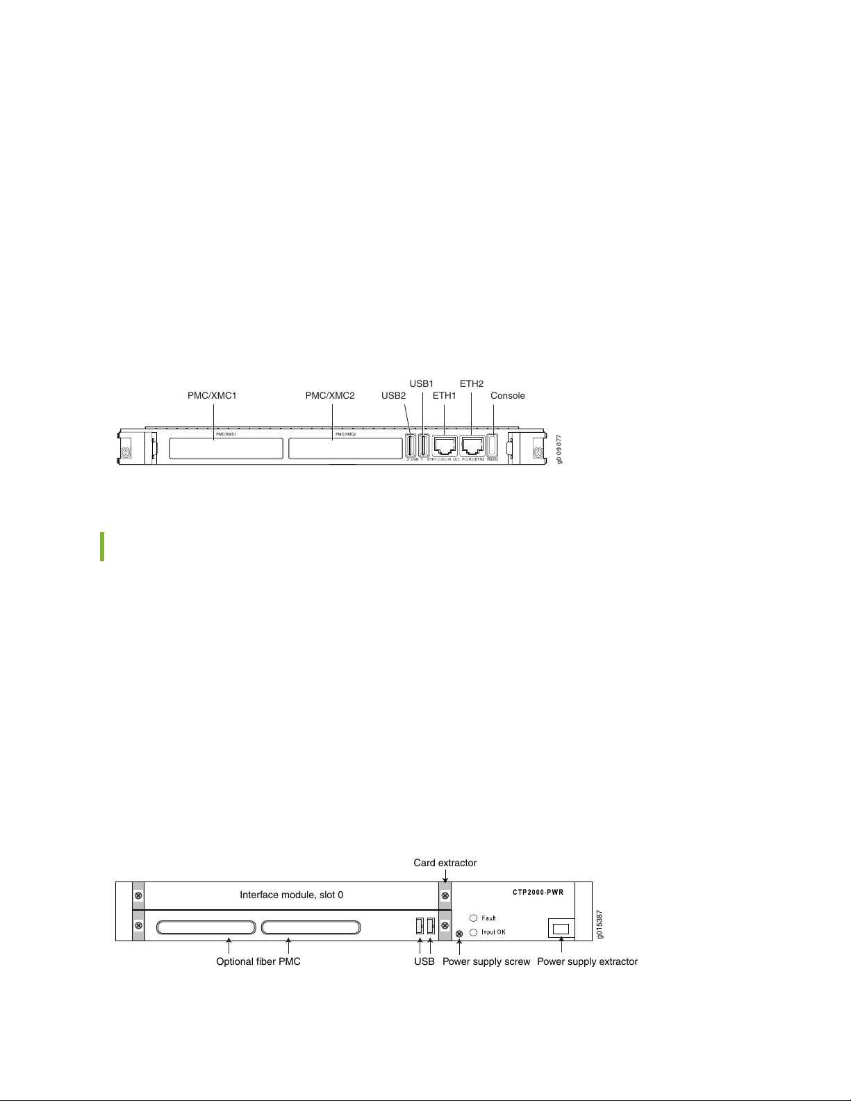
PMC—Both PMC slots are available to support compatible fiber PMC modules. For more information
g0 09 077
PMC/XMC1 PMC/XMC2
2 USB 1 ETH1 ETH2S R U P RS232H
PMC/XMC1 PMC/XMC2
USB1
USB2 ETH1
ETH2
Console
USBOptional fiber PMC
Interface module, slot 0
Card extractor
Power supply screw Power supply extractor
g015387
•
about the PMC module, see “CTP2000 PMC Module” on page 30 and “Installing a PMC on CTP2000
Platforms” on page 99.
Ethernet connection—Provides the 1-Gbps Ethernet connection to the IP network by means of a local
•
Ethernet switch or router.
Console connection—Provides an asynchronous tty connection for locally configuring the CTP Series
•
device. Because of front panel space limitations, the PP833 processor provides an RS232 serial console
via a supplied USB-to-DB9 cable (p/n 720-071594), in which the DB-9 connector has the same pinout
as a standard RS-232 DTE port.
Figure 1: PP833 Processor (AC and DC Version, Front View)
3
CTP2008 Platform
The Juniper Networks CTP2008 Circuit to Packet platform is a 3-U high, full-rack wide chassis designed
for tabletop or shelf installation. It can also be installed in a rack with the supplied rack-mounting kit. The
CTP2008 platform has one removable interface module and one removable processor module, and is
available in both AC-powered and DC-powered versions. It has a removable fan tray, and airflow is
side-to-side. Figure 2 on page 3, Figure 3 on page 4, and Figure 4 on page 5 show the CTP2008 chassis
containing the PP332 processor (which requires an RTM card for Ethernet and console port accesses).
The new PP833 processor module does not require an RTM card. All PP833 module access is located on
the front panel with all CTP serial and T1/E1 ports. If you are upgrading from the old PP310 or PP332
processor to the PP833 processor, the RTM card may be left in the node. But, none of the interfaces
(Ethernet or serial ports) on the RTM panel are functional.
Figure 2: CTP2008 Chassis Containing the PP332 Processor (AC and DC Version, Front View)
Page 11
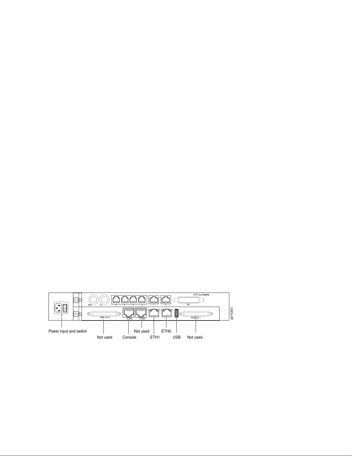
The front panel comprises the following components (see Figure 2 on page 3):
ETH1 USBConsole
Power input and switch
COM2 COM3
PMC I/O 1
PMC I/O 2
Not used Not used
Not used ETH0
g015353
Interface module—Frame processing and forwarding engines.
•
Processor module—Two slots are available on this module for an optional fiber Gigabit Ethernet or Fast
•
Ethernet PMC module. The primary SC connector is on the left side. For more information about the
PMC module, see “CTP2000 PMC Module” on page 30 and “Installing a PMC on CTP2000 Platforms”
on page 99.
Power supply extractor—Push the button to eject the power supply module.
•
The rear panel (RTM) comprises the following components (see Figure 3 on page 4 and
Figure 4 on page 5):
Clock module—Provides clock distribution between modules when the backplane is in use by voice
•
applications.
Power supply—Use a standard IEC power cord for the AC version. Use a 22-AWG fork terminal connector
•
for the DC version. There is no power redundancy for the AC version and the DC version.
There are no power switches on CTP2000 Series DC models, so a readily accessible disconnect device
must be provided as part of the electrical installation of the unit. We recommend the 22-AWG wire for
DC power terminals.
4
Ethernet connection—Provides the 1-Gbps Ethernet connection to the IP network by means of a local
•
Ethernet switch or router.
Console connection—Provides an asynchronous tty connection for locally configuring the CTP Series
•
device. On the PP310 and PP332 processors, you can connect a console directly to the COM2 port
(which is an RJ-45 type connector) found on the RTM panel.
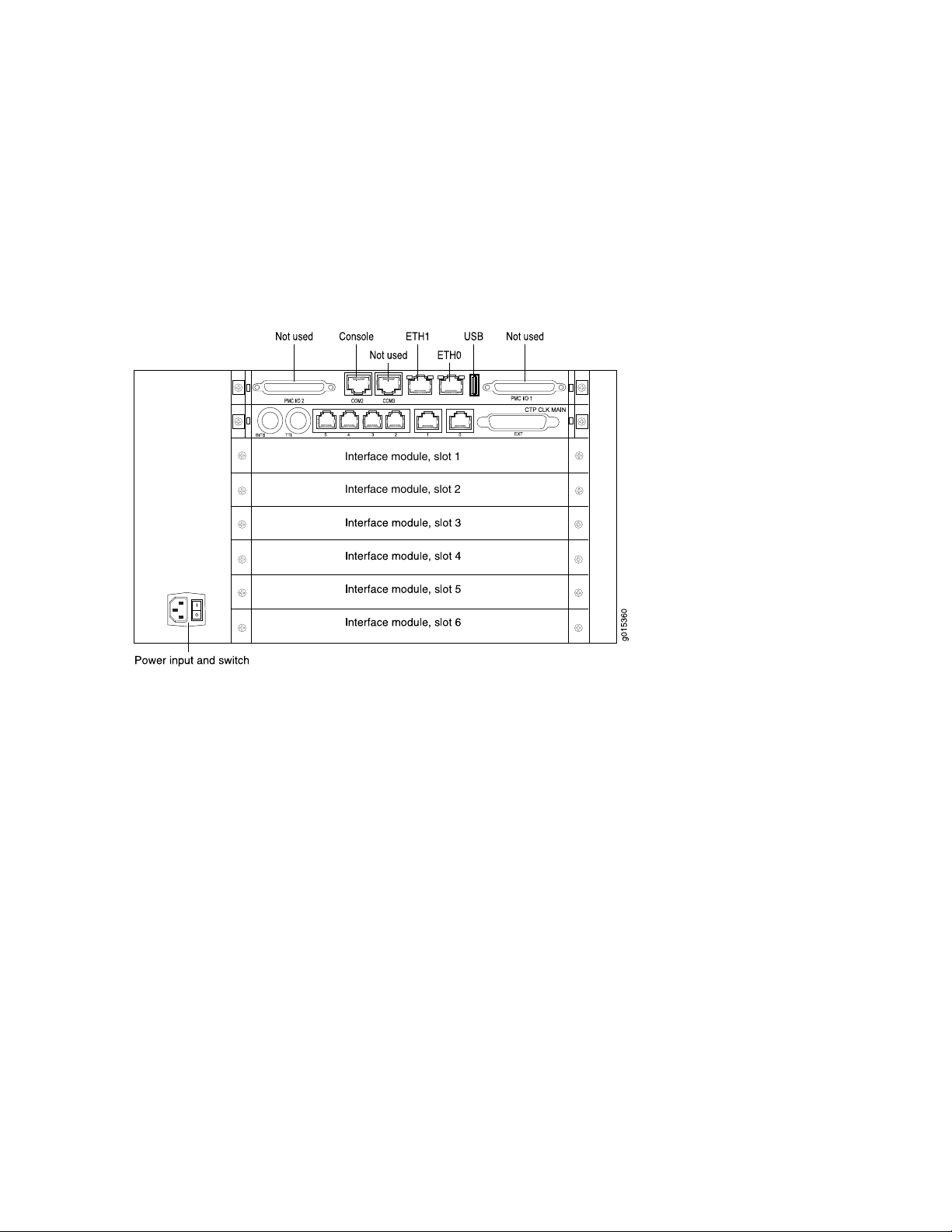
Figure 3: CTP2008 Platform Containing the PP332 Processor (AC Version, Rear View)
Page 12
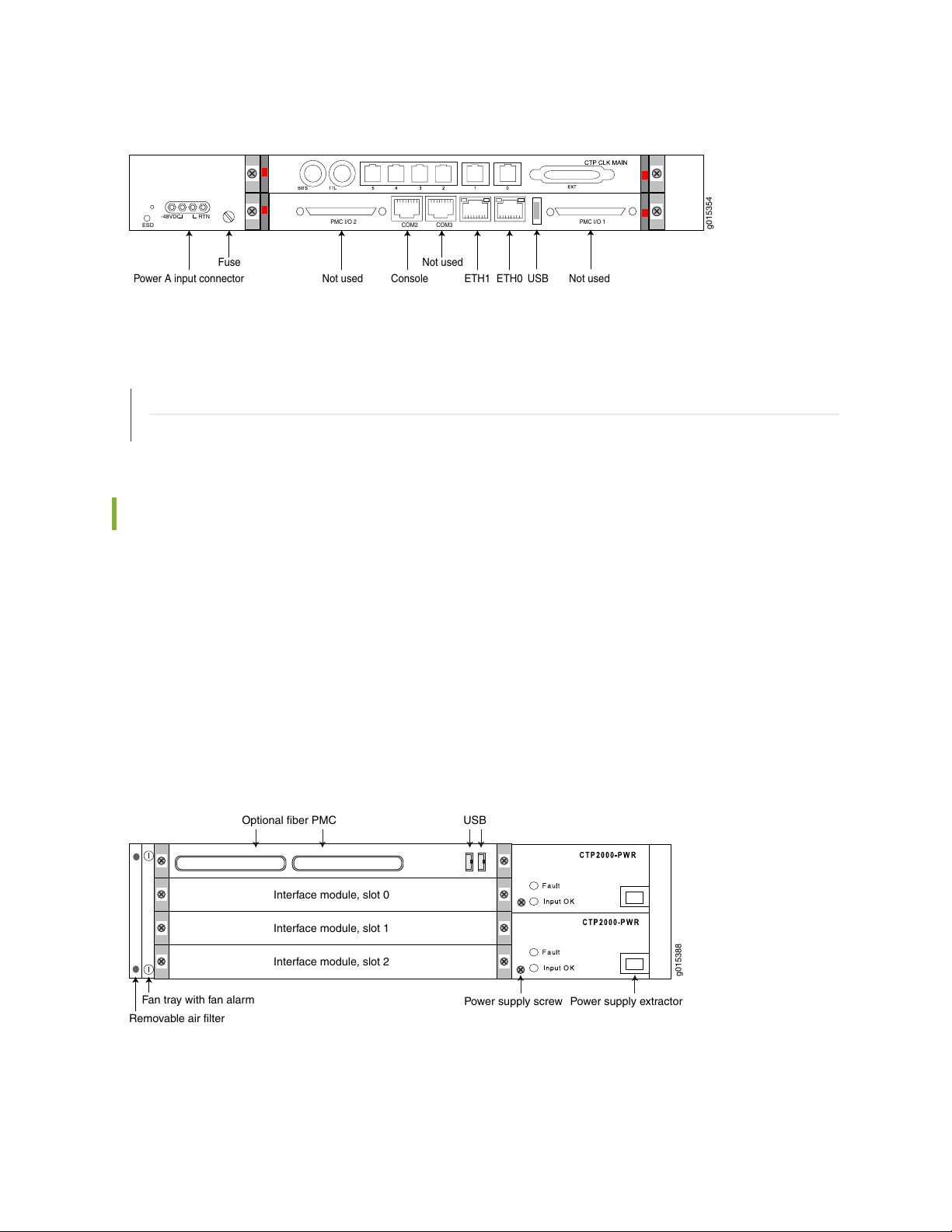
Figure 4: CTP2008 Platform Containing the PP332 Processor (DC Version, Rear View)
g015354
ETH1 USBConsolePower A input connector
COM2 COM3
PMC I/O 1PMC I/O 2
Not used Not used
Not used
ETH0
ESD
-48VDC
RTN
Fuse
USB
Optional fiber PMC
Power supply screw Power supply extractor
Interface module, slot 0
Fan tray with fan alarm
Removable air filter
Interface module, slot 1
Interface module, slot 2
g015388
RELATED DOCUMENTATION
CTP2024 Platform | 5
CTP2056 Platform | 7
5
CTP2024 Platform
The Juniper Networks CTP2024 Circuit to Packet platform can have up to three removable interface
modules and one removable processor module, and is available in both AC-powered and DC-powered
versions. It has a removable fan tray, and airflow is side-to-side. Figure 5 on page 5, Figure 6 on page 6,
and Figure 7 on page 7 show the CTP2024 chassis containing the PP332 processor (which requires an
RTM card for Ethernet and console port accesses). The new PP833 processor module does not require an
RTM card. All PP833 module access is located on the front panel with all CTP serial and T1/E1 ports. If
you are upgrading from the old PP310 or PP332 processor to the PP833 processor, the RTM card may
be left in the node. But, none of the interfaces (Ethernet or serial ports) on the RTM panel are functional.
Figure 5: CTP2024 Chassis Containing the PP332 Processor (AC and DC Version, Front View)
The front panel comprises the following components (see Figure 5 on page 5):
Page 13
Interface modules—Frame processing and forwarding engines.
•
Processor module—Two slots are available on this module for an optional fiber Gigabit Ethernet or Fast
•
Ethernet PMC module. The primary SC connector is on the left side. For more information about the
PMC module, see “CTP2000 PMC Module” on page 30 and “Installing a PMC on CTP2000 Platforms”
on page 99.
Power supply extractor—Push the button to eject the power supply module.
•
Fan tray and air filter.
•
The rear panel (RTM) comprises the following components (see Figure 6 on page 6 and
Figure 7 on page 7):
Clock module—Provides clock distribution between modules when the backplane is in use by voice
•
applications.
Power supply—Use a standard IEC power cord for the AC version. Use a 22-AWG fork terminal connector
•
for the DC version. Power redundancy is supported for the AC version and the DC version. A single IEC
power cord is used to connect the redundant AC power supply modules, which keeps the chassis turned
on in the event of failure of one of the power supplies.
6
There are no power switches on CTP2000 Series DC models, so a readily accessible disconnect device
must be provided as part of the electrical installation of the unit. We recommend the 22-AWG wire for
DC power terminals.
Ethernet connection—Provides the 1-Gbps Ethernet connection to the IP network by means of a local
•
Ethernet switch or router.
Console connection—Provides an asynchronous tty connection for locally configuring the CTP Series
•
device. On the PP310 and PP332 processors, you can connect a console directly to the COM2 port
(which is an RJ-45 type connector) found on the RTM panel.
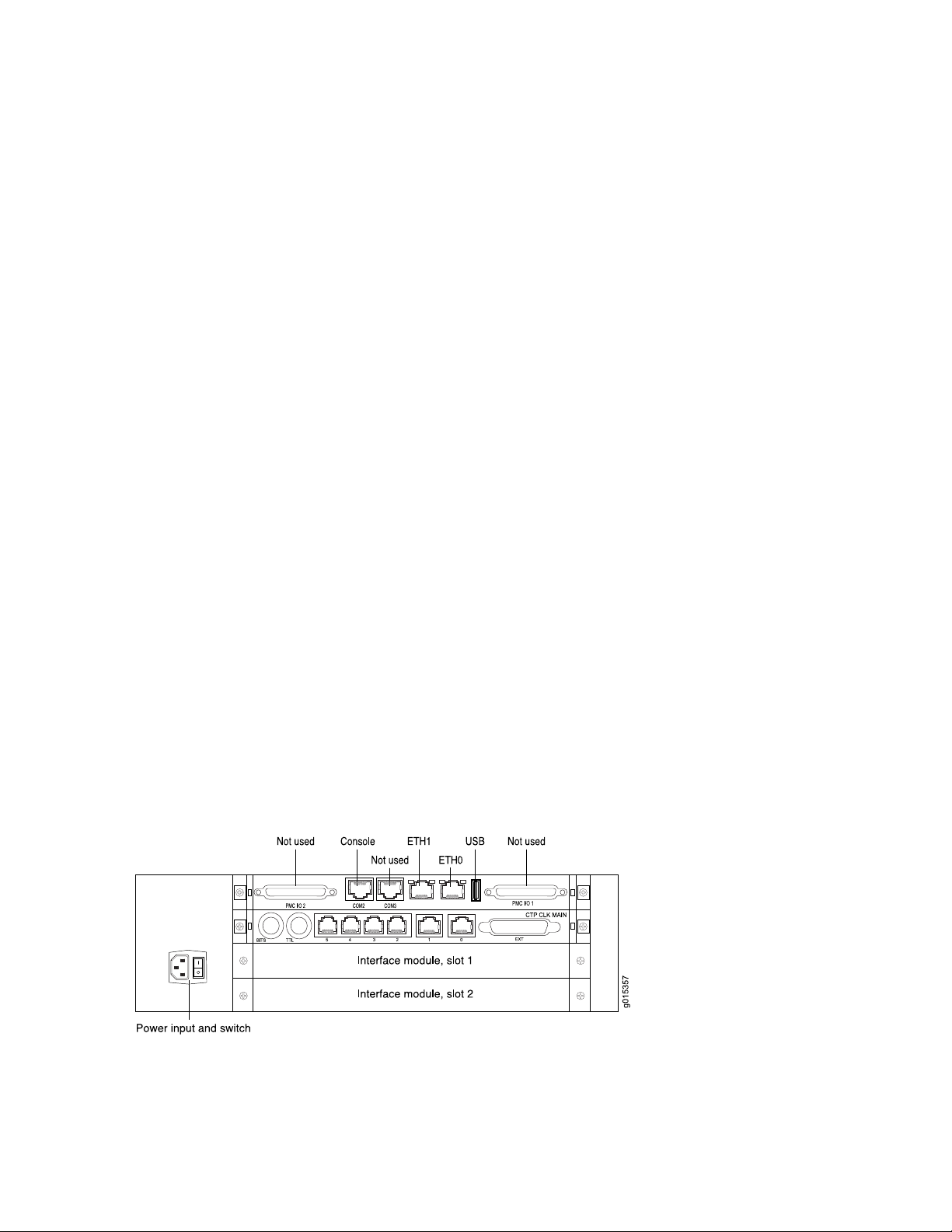
Figure 6: CTP2024 Platform Containing the PP332 Processor (AC Version, Rear View)
Page 14
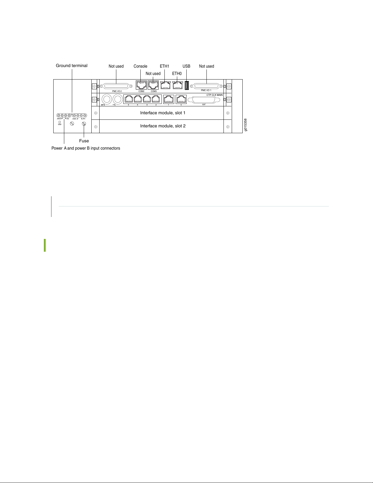
Figure 7: CTP2024 Platform Containing the PP332 Processor (DC Version, Rear View)
Power A and power B input connectors
Ground terminal
Fuse
ETH1 USBConsole
COM2 COM3PMC I/O 2
Not used
Not used
Interface module, slot 1
Interface module, slot 2
g015358
Not used
ETH0
PMC I/O 1
RELATED DOCUMENTATION
7
CTP2008 Platform | 3
CTP2056 Platform | 7
CTP2056 Platform
The Juniper Networks CTP2056 Circuit to Packet platform can have up to seven removable interface
modules and one removable processor module, and is available in both AC-powered and DC-powered
versions. It has a removable fan tray, and airflow is side-to-side. Figure 8 on page 8, Figure 9 on page 9,
and Figure 10 on page 10 show the CTP2056 chassis containing the PP332 processor (which requires an
RTM card for Ethernet and console port accesses). The new PP833 processor module does not require an
RTM card. All PP833 module access is located on the front panel with all CTP serial and T1/E1 ports. If
you are upgrading from the old PP310 or PP332 processor to the PP833 processor, the RTM card may
be left in the node. But, none of the interfaces (Ethernet or serial ports) on the RTM panel are functional.
Page 15
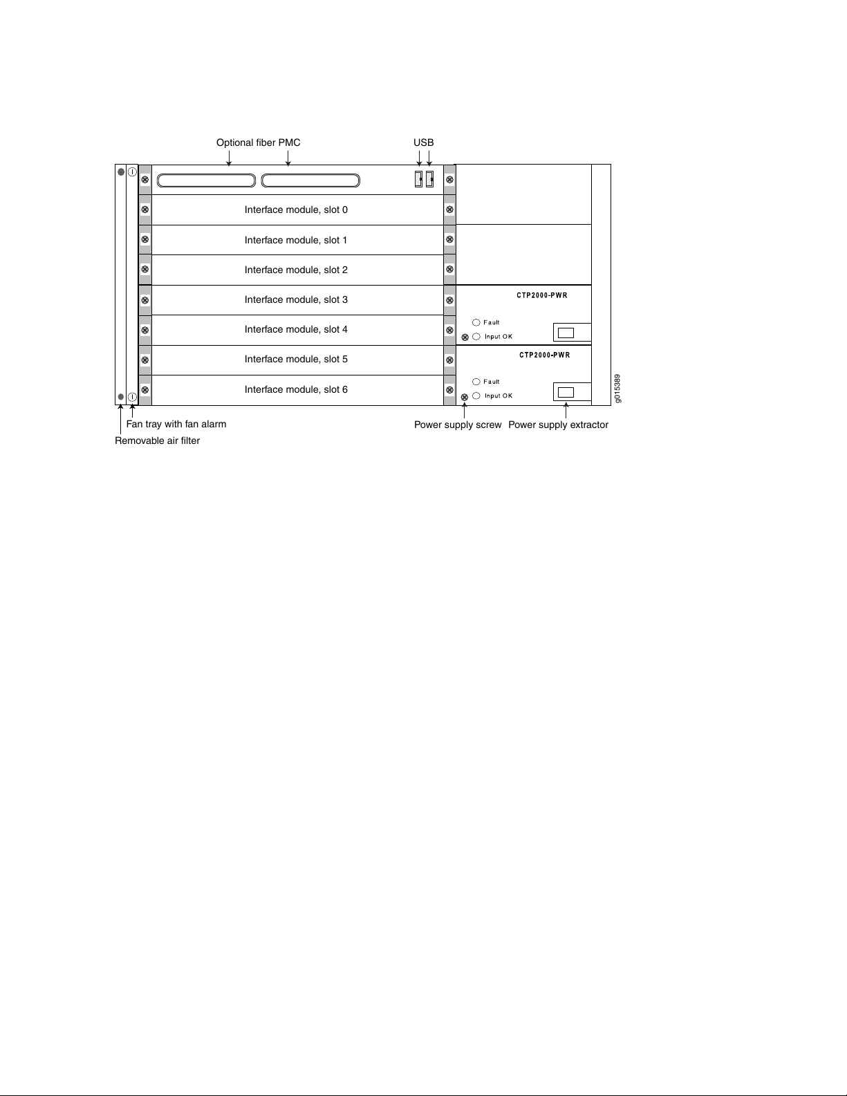
Figure 8: CTP2056 Chassis Containing the PP332 Processor (AC and DC Version, Front View)
USB
Optional fiber PMC
Power supply screw Power supply extractor
Interface module, slot 0
Interface module, slot 1
Interface module, slot 2
Interface module, slot 3
Interface module, slot 4
Interface module, slot 5
Interface module, slot 6
Fan tray with fan alarm
Removable air filter
g015389
8
The front panel comprises the following components (see Figure 8 on page 8):
Interface modules—Frame processing and forwarding engines.
•
Processor module—Two slots are available on this module for an optional fiber Gigabit Ethernet or Fast
•
Ethernet PMC module. The primary SC connector is on the left side. For more information about the
PMC module, see “CTP2000 PMC Module” on page 30 and “Installing a PMC on CTP2000 Platforms”
on page 99.
Power supply extractor—Push the button to eject the power supply module.
•
Fan tray and air filter.
•
The rear panel (RTM) comprises the following components (see Figure 9 on page 9 and
Figure 10 on page 10):
Clock module—Provides clock distribution between modules when the backplane is in use by voice
•
applications.
Power supply—Use a standard IEC power cord for the AC version. Use a 22-AWG fork terminal connector
•
for the DC version. Power redundancy is supported for the AC version and the DC version. A single IEC
power cord is sufficient to connect the redundant AC power supply modules, which keeps the chassis
turned on in the event of failure of one of the power supplies.
There are no power switches on CTP2000 Series DC models, so a readily accessible disconnect device
must be provided as part of the electrical installation of the unit. We recommend the 22-AWG wire for
DC power terminals.
Page 16
Ethernet connection—Provides the 1-Gbps Ethernet connection to the IP network by means of a local
Interface module, slot 1
Interface module, slot 2
•
Ethernet switch or router.
Console connection—Provides an asynchronous tty connection for locally configuring the CTP Series
•
device. On the PP310 and PP332 processors, you can connect a console directly to the COM2 port
(which is an RJ-45 type connector) found on the RTM panel.
Figure 9: CTP2056 Platform Containing the PP332 Processor (AC Version, Rear View)
9
Page 17
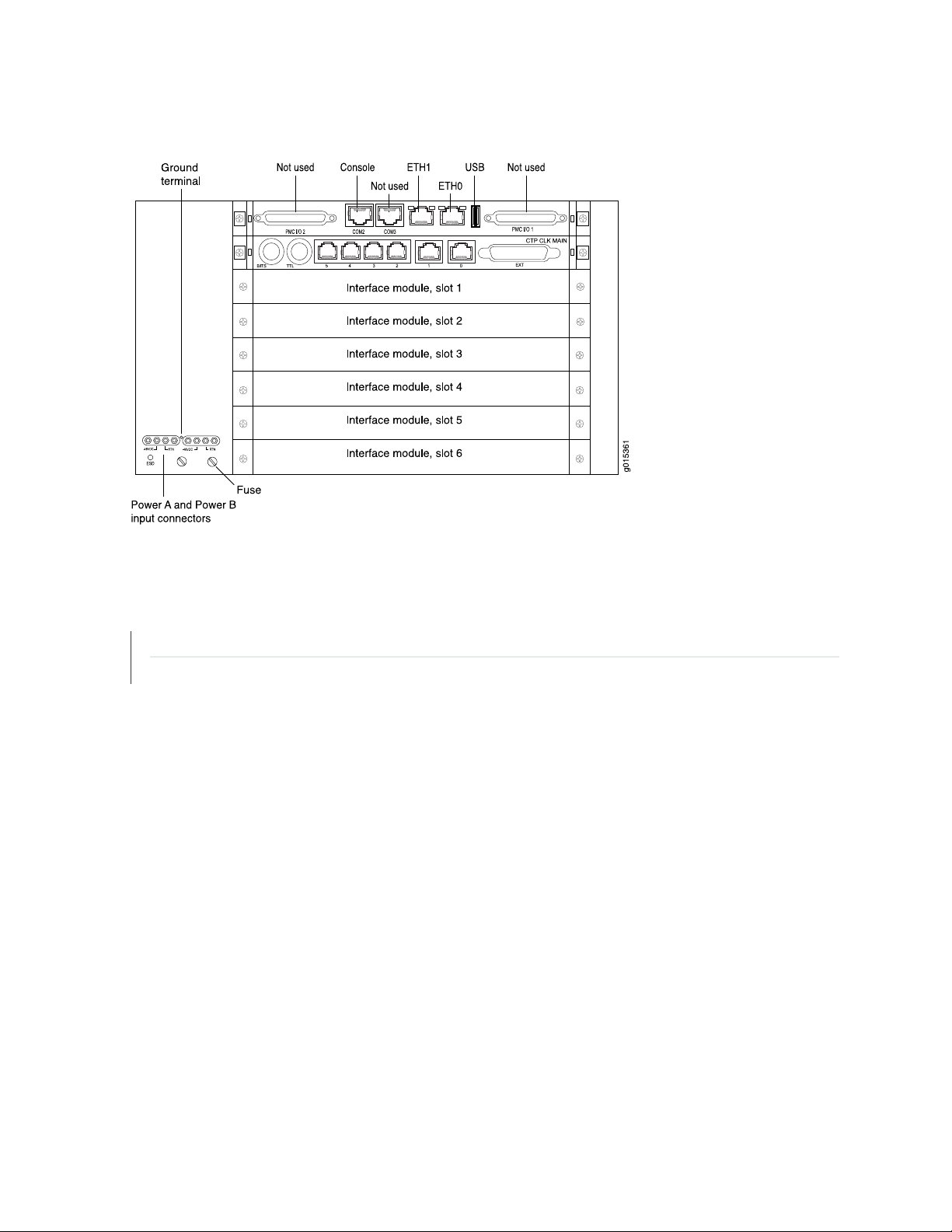
Figure 10: CTP2056 Platform Containing the PP332 Processor (DC Version, Rear View)
10
RELATED DOCUMENTATION
CTP2008 Platform | 3
CTP2024 Platform | 5
Page 18

CHAPTER 2
CTP2000 Series Interface Modules
IN THIS CHAPTER
CTP2000 Serial Interface Modules | 11
CTP2000 Multiservice Interface Module | 12
CTP2000 T1/E1 Interface Module | 13
CTP2000 Compression Module | 13
CTP2000 4WE&M Interface Module | 14
CTP2000 2W-FXS and 2W-FXO Interface Modules | 20
CTP2000 8P-IRIG Interface Module | 26
11
CTP2000 Clock Interface Modules | 27
CTP2000 PMC Module | 30
CTP2000 Serial Interface Modules
The Juniper Networks CTP2008, CTP2024, and CTP2056 Circuit to Packet platforms have up to one,
three, and seven serial interface modules, respectively. The interface modules are interchangeable between
the platforms.
The following interface modules have two 100-pin connectors similar to the connectors provided on the
CTP1004 and CTP1012 platforms. Each connector provides four ports by means of the quad cable. (See
“Cabling the CTP2000 Platform Overview” on page 108.) The lowest-numbered ports start at the top right.
CTP2000 IM-8P—Provides the standard software-configurable data interfaces, including EIA530,
•
EIA530A, RS-232, and V.35; 8 port.
CTP2000 IM-8P-T1—Provides the standard software-configurable data interfaces, plus a configurable
•
T1/E1 interface; 8 port.
CTP2000 IM-8P-V—Provides the standard software-configurable data interfaces, plus a configurable
•
4WTO interface; 8 port.
Page 19

Figure 11: Sample Serial Interface Module
g015452
CTP2000 IM 8PIRIG
CTP2000 IM 8P MS
RELATED DOCUMENTATION
Cabling the CTP2000 Platform Overview | 108
CTP2000 Serial Interface Module Pinouts | 52
CTP2000 T1/E1 Interface Module | 13
CTP2000 Compression Module | 13
CTP2000 4WE&M Interface Module | 14
CTP2000 2W-FXS and 2W-FXO Interface Modules | 20
CTP2000 8P-IRIG Interface Module | 26
12
CTP2000 Multiservice Interface Module
The Juniper Networks CTP2000 Circuit to Packet platform optionally includes an 8-port Serial Multiservice
Interface module (CTP2000-IM-8p-MS) as shown in Figure 12 on page 12.
Figure 12: CTP2000 Serial Multiservice Interface Module
The cable used with the Serial Multiservice Interface module is CTP-CBL-4Q.
The module can operate in the following modes:
Audio—Provides single and dual channel audio support for varying quality audio from 8-bit, 8-KHz quality
•
to 8-bit up to 16-bit, 48-KHz quality (CD quality).
4WTO—Provides single and dual channel audio support for 8-bit, 8-KHz quality with squelch support
•
for radio backhaul. In 4WTO mode, the Multiservice interface module is interoperable with 4WTO
daughter cards.
IRIG—Enables an interrange instrumentation group time code (IRIG-B) signal to be transported through
•
an IP network.
TDC—Provides combined time-correlated support for IRIG/NRZ data for telemetry applications.
•
Page 20

The interface module is supported on CTP bundles; You use the bundles to configure the modes of
0 1 32
7654
CTP2000 IM-T1/E1
g015363
operation.
RELATED DOCUMENTATION
Serial Multiservice Interface Module Overview
CTP2000 T1/E1 Interface Module
The CTP2000 Series T1/E1 interface module has RJ-48 ports numbered 0–7 left to right. It provides a
configurable eight-port E1 (2.048 MHz) or T1 (1.544 MHz) interface with AMI or B8ZS encoding. (See
Figure 13 on page 13.) You can use the eight port T1/E1 interface module to interconnect digital voice
applications with CESoPSN bundles.
13
Figure 13: CTP2000 IM-8P-T1/E1 Interface Module
RELATED DOCUMENTATION
CTP2000 Serial Interface Modules | 11
CTP2000 Compression Module | 13
CTP2000 4WE&M Interface Module | 14
CTP2000 2W-FXS and 2W-FXO Interface Modules | 20
CTP2000 8P-IRIG Interface Module | 26
T1/E1 Interface Module Pinouts | 51
Cabling a CTP2000 T1/E1 Interface Module | 111
CESoPSN Bundle Overview
CTP2000 Compression Module
The CTP2000 Series Compression Module enables serial data and voice bundles to be compressed and
passed through a CTP2000 platform. It provides twice the digital signal processor (DSP) density of the
original compression module. (See Figure 14 on page 14.)
Page 21

Voice bundles originating from the CTP2000 IM-8P-T1/E1, analog CTP2000 IM-4WE&M,
Not used Not used Not used
Fail
Reset
g015364
CTP2000-IM-2W-FXS, and CTP2000-IM-2W-FXO modules can use the CTP2000 Compression 2 High
Density Interface Module to compress voice bundles. Voice bundles ranging from 1–24 channels on a T1
module, 1–30 channels on an E1 module, and 1–8 channels on a 4WE&M module can be bundled and
connected through the Compression 2 High Density Module to compress the voice bundle and build the
IP packet.
NOTE: CTP2000 Compression Module can no longer be purchased.
Figure 14: Compression Module
14
The Compression Module supports these compression algorithms:
G.711 (64k)
•
G.729AB (8k)
•
This module supports Mu-Law and A-Law companding, echo cancellation, silence suppression, fax/modem
detection, and tone relay. You can configure the compression options when you configure the voice bundle.
RELATED DOCUMENTATION
CTP2000 T1/E1 Interface Module | 13
CTP2000 4WE&M Interface Module | 14
CTP2000 2W-FXS and 2W-FXO Interface Modules | 20
CTP2000 4WE&M Interface Module
The CTP2000 Series 4WE&M interface module has eight 4-wire E&M ports. It is used with voice
compression (VCOMP) bundles in CTP2000 models and can be used only with a CTP2000 compression
module. You can use the 4WE&M interface module to interconnect analog 4WE&M voice applications
with CESoPSN bundles.
Page 22
NOTE: You can use the eight port T1/E1 interface module to interconnect digital voice
Port signaling LEDs
Not used
RJ-21 25-pair connectors
4WEM RTM
g015366
applications with CESoPSN bundles.
Four-wire audio interfaces with E and M signaling interfaces (4WE&M) are commonly used as trunks
between a central office (CO) and a private branch exchange (PBX). E and M is a type of supervisory line
signaling that uses separate leads, called the "E" (ear) lead and "M" (mouth) lead and are traditionally used
in the telecommunications industry. In 4WE&M signaling, two wires are used to receive and two wires are
used to transmit, incorporating simplex control and differential payload in each channel. Type I, II, and V
signaling is supported.
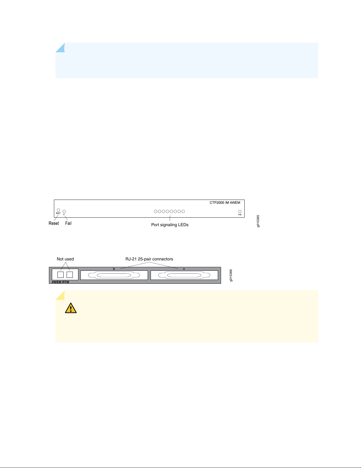
The 4WE&M interface module consists of a front card and a rear transition module (RTM). Port interfaces
are located on connectors A and B of the RTM. (See Figure 15 on page 15 and Figure 16 on page 15.) The
RJ-45 connectors are not used.
Figure 15: CTP2000 4WE&M Module
15
Figure 16: 4WE&M RTM
CAUTION: Power to the RTM is supplied from the interface module. Using an RTM
other than those matched to the interface module may result in damage to both the
interface module and the RTM. For example, never install a clock module RTM directly
behind a 4WE&M interface module.
Voice ports can be used only by voice compression bundles (VCOMP) and cannot be used for CTP, SAToP,
or CESoPSN bundles. There is no software configuration of 4WE&M ports. Signaling type is configured
by means of jumpers (see Figure 18 on page 16 and Table 1 on page 16). One or more 4WE&M ports can
be mapped to a VCOMP bundle. The bundle configuration specifies the remote destination, the local port
or ports transported by the bundle, voice compression options, as well as other configuration options.
Page 23
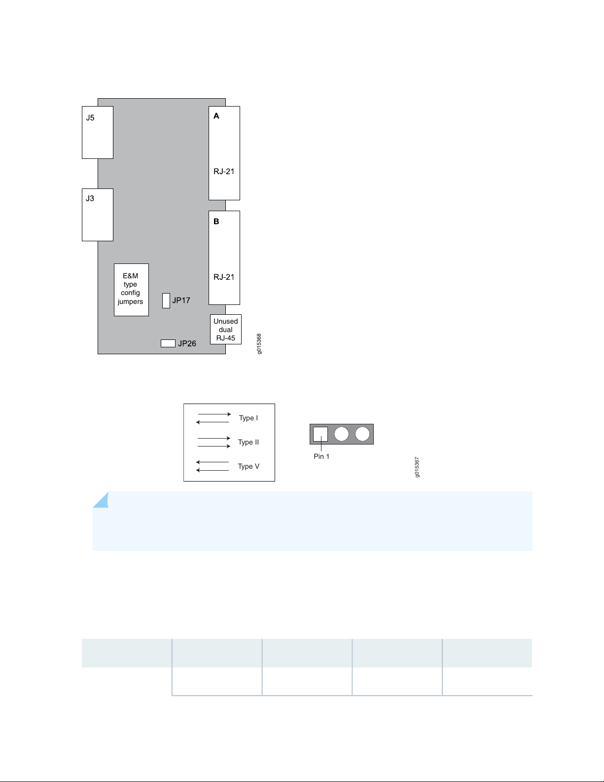
Figure 17: Jumper Locations on the RTM
g015368
E&M
type
config
jumpers
Unused
dual
RJ-45
Pin 1
Type I
Type II
Type V
g015367
16
Figure 18: Jumper Positions for Signaling Types
NOTE: Jumper JP17 must be in Position 1-2 (see Table 1 on page 16) if any ports are set for
Type II signaling. This jumper ties all signal battery (SB) signals to battery voltage (–48V).
Jumper JP26 is used to connect all signal grounds (SG) to the chassis ground. When jumper JP26 is in
Position 1-2, the signal ground is connected to the chassis ground. In Position 2-3, it is isolated from the
chassis ground.
Table 1: Jumper Positions for Configuring Port Signaling Type
Signaling Type VSignaling Type IISignaling Type IJumper
Position 1-2Position 2-3Position 1-2JP1Port 0
Page 24

Table 1: Jumper Positions for Configuring Port Signaling Type (continued)
17
Signaling Type VSignaling Type IISignaling Type IJumper
Position 1-2Position 2-3Position 2-3JP9
Position 1-2Position 2-3Position 1-2JP2Port 1
Position 1-2Position 2-3Position 2-3JP10
Position 1-2Position 2-3Position 1-2JP3Port 2
Position 1-2Position 2-3Position 2-3JP11
Position 1-2Position 2-3Position 1-2JP4Port 3
Position 1-2Position 2-3Position 2-3JP12
Position 1-2Position 2-3Position 1-2JP5Port 4
Position 1-2Position 2-3Position 2-3JP13
Position 1-2Position 2-3Position 1-2JP6Port 5
Position 1-2Position 2-3Position 2-3JP14
Position 1-2Position 2-3Position 1-2JP7Port 6
Position 1-2Position 2-3Position 2-3JP15
Position 1-2Position 2-3Position 1-2JP8Port 7
Position 1-2Position 2-3Position 2-3JP16
The rear transition board uses two RJ-21 25-pair Telco connectors labeled A and B to interface the audio
and control connections for eight E&M channels.
NOTE: Because of space limitations, a 180º RJ-21 connector is required. The CTP 4WE&M RTM
supports clips to secure the RJ-21 cable connections to the RTM.
The R1/T1 pair and the R/T pair are the audio inputs and outputs of each port, respectively. For example,
the audio input pair for port 0 is R1 and T1 on pins 2 and 27 of connector A. The audio output pair for
port 0 is R and T on pins 1 and 26.
Page 25

See Table 2 on page 18 for signal definitions. See “CTP2000 4WE&M Interface Connector Pinouts” on
page 45 for the connector A and B pinouts.
Table 2: Signal Definitions
Signal DefinitionSignal Name
Audio transmit pair, 600 OhmPort x T, R
Audio receive pair, 600 OhmPort x T1, R1
E lead–outputPort x E
M lead–inputPort x M
Input for signal ground for signaling type IIPort x SG
18
Port x SB
GND
Output signal battery (–48V) for signaling type II. Note that JP17 must be in
position 1-2.
Signal ground. E and M leads are referenced to this ground for signaling types
I and V. Use JP26 to connect this ground to chassis ground.
Supervisory Signaling
Supervisory signaling is the means by which a telephone user requests a service or initiates a call. The
signaling unit (CTP platform) interacts with the trunk unit (PBX) by means of either two or four leads,
depending on the signaling type. (See Figure 19 on page 19.) The signaling unit controls the E lead, whereas
the trunk side controls the M lead. The two signaling states are on-hook and off-hook. During inactivity
both units are on-hook. See Table 3 on page 20 for a summary of signaling types supported by the CTP2000
4WE&M module.
NOTE: 4WE&M and 4WTO audio paths are always up independent of the signaling state.
Page 26
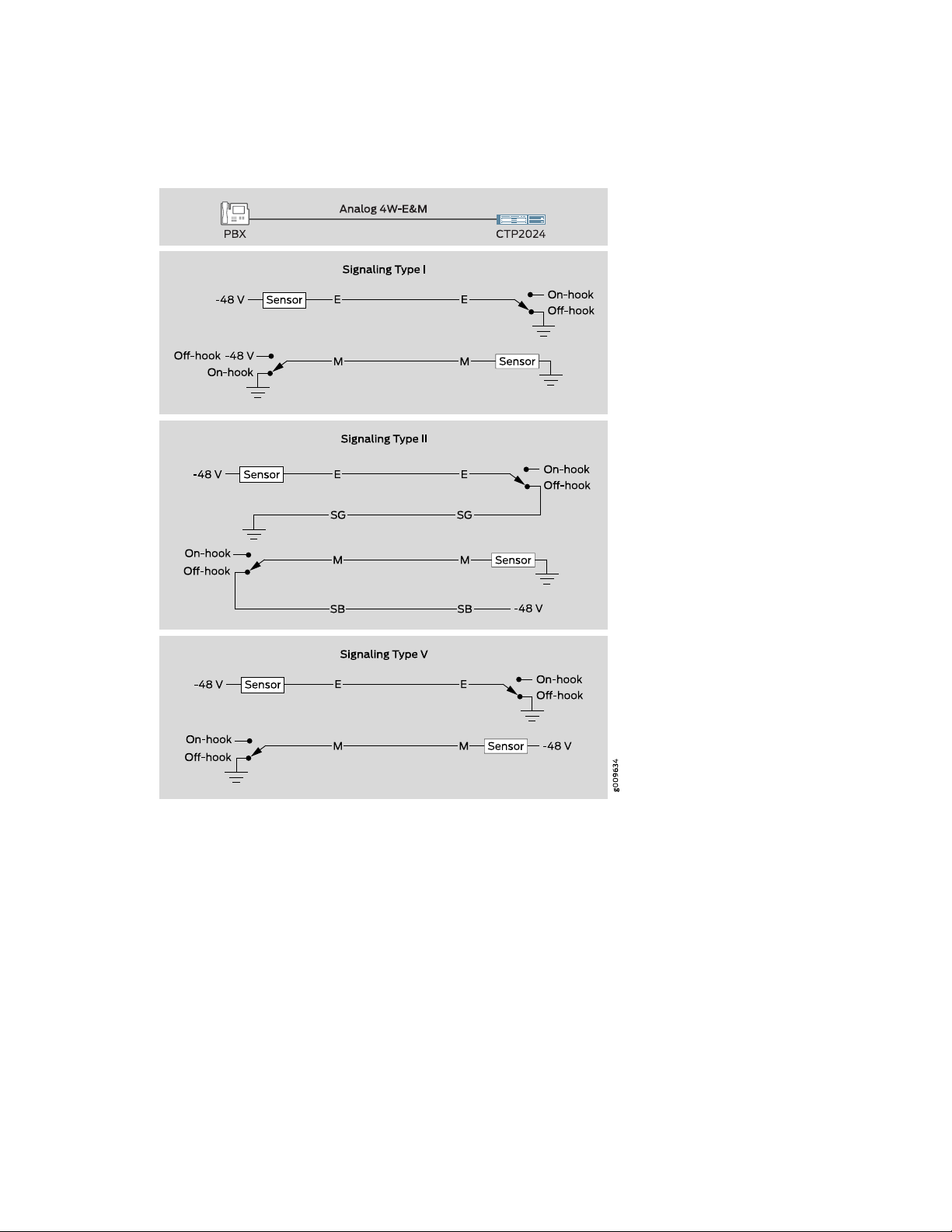
Figure 19: Analog 4WE&M Signaling Types
19
Type I uses two leads—the E and M leads—for signaling. During inactivity, the E lead is open and the M-lead
is connected to ground. The CTP device connects the E lead to a grounding point to signal off-hook, and
the PBX connects the M lead to the battery (–48 V) to signal off-hook. Note that two signaling units cannot
be connected back-to-back. With type I signaling, the signaling and trunk units must be connected by
means of a common ground. Because the two sides are not isolated, they are susceptible to noise in the
audio channels.
Type II uses four leads—E, SG, M, and SB—for signaling. During inactivity, both the E and M leads are open.
To signal off-hook, the PBX connects the M lead to SB and the CTP device connects the E lead to SG.
Note that two signaling units can be connected back-to-back if the appropriate signaling leads are swapped.
With Type II signaling, the signaling unit and the trunk do not share a common ground.
Page 27

Type V uses two leads, the E and M leads, for signaling. During inactivity, both the E and M leads are open.
The CTP device signals off-hook by connecting the E lead to ground. The trunk circuit signals off-hook by
connecting the M lead to ground. As with type I, with type V signaling, the two units share a common
ground. Type V signaling allows for signaling units to be connected back-to-back.
Table 3: Supported Signaling Types for the CTP2000 4WE&M Module
CTP (E Lead)PBX (M Lead)Signaling LeadsSignaling Type
Off-hookOn-hookOff-hookOn-hook
GroundOpenBatteryGroundE, MI
SGOpenSBOpenE, M, SG, SBII
GroundOpenGroundOpenE, MV
20
RELATED DOCUMENTATION
CTP2000 4WE&M Interface Connector Pinouts | 45
CTP2000 Serial Interface Modules | 11
CTP2000 T1/E1 Interface Module | 13
CTP2000 Compression Module | 13
CTP2000 2W-FXS and 2W-FXO Interface Modules | 20
CTP2000 8P-IRIG Interface Module | 26
CESoPSN Bundle Overview
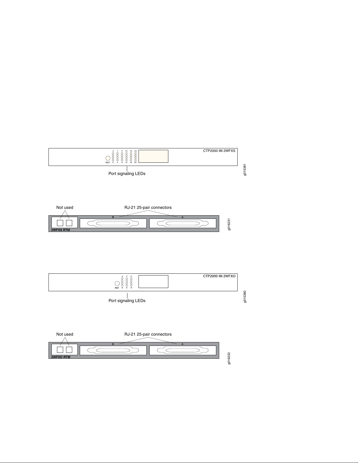
CTP2000 2W-FXS and 2W-FXO Interface Modules
The CTP2000 2W-FXS and CTP2000 2W-FXO interface modules provide analog support for voice
applications. The 2W-FXS module has 24 two-wire FXS ports and the 2W-FXO interface module has 12
two-wire FXS ports. Both are paired with an RTM.
FXS interfaces point to the subscriber and supply battery and ring voltage. Some FXS devices also provide
•
dial tone, but CTP FXS interfaces do not. FXS interfaces detect when the attached FXO interface goes
off-hook and on-hook. An FXS interface is a two-wire interface; the leads are called the tip (T) and the
ring (R).
FXO interfaces point to the central office. An analog phone is an example of an FXO device. The FXO
•
interface must detect ring voltage (the analog phone rings) and provide on- and off-hook indication to
Page 28
the FXS interface. An FXO interface is a two-wire interface; the leads are called the tip (T) and the ring
RST
2016
128
40
2319151173
CTP2000 IM 2WFXS
Port signaling LEDs
g015381
Not used
RJ-21 25-pair connectors
2WFXS RTM
g016231
Port signaling LEDs
g015380
Not used
RJ-21 25-pair connectors
2WFXO RTM
g016232
(R).
You can interconnect the following voice applications with CESoPSN bundles:
Analog 4WE&M voice applications using the 4WE&M interface module
•
Digital voice applications using the T1/E1 interface module
•
Both interface modules consist of a front module and an RTM. See Figure 20 on page 21 and
Figure 21 on page 21 for the CTP2000 2W-FXS interface module.
Figure 20: Front Panel of CTP2000 2W-FXS Interface Module
21
Figure 21: Rear Panel of CTP2000 2W-FXS RTM
See Figure 22 on page 21 and Figure 23 on page 21 for the CTP2000 2W-FXO interface module.
Figure 22: Front Panel of CTP2000 2W-FXO Interface Module
Figure 23: Rear Panel of CTP2000 2W-FXO RTM
Both modules use connector A on the RTM. For both modules, connector B and the RJ-45 connectors are
not used. See “CTP2000 FXS and FXO Interface Module Cables and Pinouts” on page 48 for connector
pinout information.
You set the signaling by using the software on both modules. You cannot reconfigure the jumper parameters.
Page 29

Required Cables and Pinouts
The CTP2000 2W-FXS and 2W-FXO interface modules require the use of double-shielded cables (copper
braid plus aluminum mylar foil) to ensure EMI compliance. See “CTP2000 FXS and FXO Interface Module
Cables and Pinouts” on page 48 for particulars about cable pinouts.
Analog FXS/FXO Loop-Start Signaling
There are two basic signaling protocols for FXS/FXO interfaces: loop-start and ground-start. Residential
telephones use loop-start. Ground-start is typically used between a CO and a PBX to prevent “glare.” Glare
occurs when a call is established by the FXS device and the FXO device tries to make a call before the ring
has been detected.
When a call is initiated from the CO (or FXS) side, the FXS interface puts an AC ring voltage on the R lead
(typically 70-90 Vrms). This ring voltage generates the ringing that you hear on an analog phone. When
the FXO device answers the call (someone picks up the handset), the switch is closed between the T and
R leads to complete a loop between the battery and ground in the FXS device. The FXS device detects
the current, which flows from the battery (–48 V) through the R leads and back through the T leads to
ground and stops the ring voltage.
22
When a call is initiated by the CPE (or FXO) device, the device goes off-hook, closing the connection
between the T and R leads. The FXS device senses the current flow in the loop. Either the attached FXS
device, or an upstream FXS device, provides dial tone to the FXO device after it is ready to accept the
digits for the call destination. Providing dial tone is a form of start-dial supervision.
On the FXO device, when the device is on-hook, there is an open lead between the T and R leads. When
the device is off-hook, the T and R leads are shorted with a typical load of ~300 Ohms. With loop-start,
the T and R leads on the FXO interface can be switched without adversely affecting the signaling.
Glare occurs when a call is established by the FXS device and the FXO tries to make a call before the ring
has been detected. Because it takes time for the FXO device (or person about to place a call) to detect
ringing, it is possible for the FXS and FXO devices to both seize the line without knowledge that the other
end has done so. Ground-start circuits were established the minimize the possibility of glare. See “Analog
FXS/FXO Ground-Start Signaling” on page 23.
Answer Supervision
Answer supervision is a signal used by the phone companies to determine when to start billing the originator
of the call. Without answer supervision, you could get billed for the time the phone was ringing, even if
the call was never picked up. When the FXS device has detected that the FXO device has gone off-hook,
it reverses the polarity between the T and R leads for the duration of the call.
Disconnect Supervision
Disconnect supervision is a signal sent by the FXS device to the FXO device to indicate that the call has
ended. The disconnect supervision signal can be either a battery reversal, battery denial (more than 350
ms), or a tone.
Page 30

Note that loop-start circuits are not sensitive to tip/ring reversal. For example, the tip on the FXO device
may be connected to either the tip or ring on the FXS.
Analog FXS/FXO Ground-Start Signaling
Ground-start signaling is used to minimize the potential for glare. Unlike loop-start circuits, ground-start
circuits operate correctly only when the FXO tip is connected to the FXS tip and the FXO ring is connected
to the FXS ring. Also, unlike loop-start circuits, the FXS and FXO grounds must be at the same potential.
When on-hook, the FXO ring is not connected to either the tip or ground. Likewise, when idle, the FXS
tip is not connected to ground. When a call is initiated from the CO (FXS side), the FXS grounds its tip and
applies an AC ring voltage to the R lead. The FXO device senses the grounded tip and AC ring voltage, and
then goes off-hook by closing the loop (connecting R to T). The FXO has 100 ms to respond to the grounded
tip/ring voltage. This time constraint is used to minimize glare. Once the FXO has closed the loop, the call
proceeds as in the loop-start case.
When a call is initiated by the customer (FXO) side, the FXO starts by grounding the R lead. The FXS side
responds by grounding its T lead. After the FXO has detected the grounded T lead, it closes the loop by
removing the R lead from ground and closing the loop. With ground-start circuits, a far-end disconnect
(FXS side) is indicated by the FXS disconnecting the tip from ground. The FXO senses the tip disconnect
and goes on-hook by opening the loop.
23
Digital Signaling
Channel banks are often used to multiplex and demultiplex FXS or FXO interfaces onto T1 or E1 digital
circuits. In the process, the analog signal is converted into pulse code modulation (PCM) and carried by
one of the channels in the time-division multiplexing (TDM) circuit. For the interface to function properly,
it must be able to signal the remote end of the T1/E1 connection as well as respond to signals from the
remote end. Signaling is carried over the TDM circuit using either channel-associated signaling (CAS) or
common-channel signaling (CCS). Generally, four signaling bits (A, B, C, and D) may be used; however, two
signaling bits are most common (A and B).
For CTP analog voice products to work with digital devices, A and B bits are generated and transported
across the network.
Digital FXS/FXO Loop-Start Signaling
For loop-start signaling of FXS and FXO interfaces, the A bit is used to indicate the state of the current
loop, whereas the B bit is used for ringing. In the idle state (no ringing, FXO on-hook), A=0 and B=1. A=1
when the FXO is off-hook. Ringing is signaled by the B bit toggling between 0 and 1. Typically the toggling
is 2 seconds off and 4 seconds on. For digital loop-state, the signaling is bidirectional.
Because hook indication is detected by the analog FXS interface, this device is responsible for generating
the A bit. Likewise, because the analog FXS interface generates the ring voltage, this device must respond
Page 31

to the B bit. Because the signaling is bidirectional, the FXS side must echo the B bit when sending out the
A bit.
The same logic applies to the FXO interface. The FXO device goes on/off-hook. It must respond to the A
bit, going off-hook when A transitions from 0 to 1, and going on-hook when A goes from 1 to 0. The analog
FXO interface detects ringing; therefore, it is responsible for generating the B bit value. The FXO device
must echo the A value when sending out the digital signaling over the network.
Two situations for this call sequence must be considered: when the CTP is the FXO device and when the
CTP platform is the FXS device. In both cases, before the call starts, the FXO is on-hook (A=1) and there
is no ringing (B=1).
For an analog CTP FXS interface, before the call starts, the CTP interface must generate A=0 and send
•
both A=0 and B=1. When the call initiates from the CO, the B bit is toggled. In response to this toggling,
the CTP device generates a ring voltage on the analog FXS interface. When the attached FXO device
goes off-hook, the CTP FXS interface detects the off-hook, sets the A bit to 1, and stops the ring voltage.
During the call, the CTP device sends A = B = 1 signaling bits. At the end of the call, the FXO device
goes back to on-hook, the CTP detects the on-hook, sends out A=0 and B=1 signaling bits, and the circuit
returns to the idle state.
24
For an analog CTP FXO interface, before the call starts the FXO is on-hook and no ringing is generated
•
by the attached FXS device. In this, the idle state, the CTP interface generates B=1 and sends both A=0
and B=1. When the call comes in from the CO, the CTP FXO interface detects ring voltage and starts
toggling the B bit. When the other end of the VCOMP bundle goes off-hook, it sends A=1 to the CTP.
In response, the CTP FXO interface closes the loop, going off-hook. With ringing stopped, the CTP
interface sends A = B = 1 during the call. At the end of the call the interface is again idle, and the CTP
interface sends A=0 and B=1 signaling bits.
Digital FXS/FXO Ground-Start Signaling
Unlike loop-start interfaces, in which the FXO and FXS each separately control a single signaling bit, with
ground-start signaling each side controls both the A and B bits. We must consider each interface when
the call is initiated by either interface. (See Table 4 on page 24, Table 5 on page 25, Table 6 on page 25,
and Table 7 on page 25). In all cases, when the FXO/FXS interface is idle, the FXO interface generates A
= B = 1 signaling bits and the FXS A = 0, B = 1. When a call is in progress, either side initiates a call
termination if it receives these signaling bits. For example, an FXS goes on-hook if it receives A=B=1
signaling bits.
Table 4: Ground-Start Signaling at FXO Interface for Call Initiated by the FXO Interface
Signaling Bits from FXOSignaling Bits to FXO
11 (A=1, B=1)01 (A=0, B=1)Idle (before call starts)
1100FXO grounds ring
0100FXS goes off-hook (grounds tip)
Page 32

Table 4: Ground-Start Signaling at FXO Interface for Call Initiated by the FXO Interface (continued)
Signaling Bits from FXOSignaling Bits to FXO
0111FXO goes off-hook (closes loop)
0111Duration of call
Table 5: Ground-Start Signaling at FXO Interface for Call Initiated by the FXS Interface
Signaling Bits from FXOSignaling Bits to FXO
11 (A=1, B=1)01 (A=0, B=1)Idle (before call starts)
00/01 (B-bit toggles)01FXS goes off-hook (grounds tip and
sends AC ring signal)
0111FXO goes off-hook (closes loop)
25
0111Duration of call
Table 6: Ground-Start Signaling at FXS Interface for Call Initiated by the FXS Interface
Signaling Bits from FXSSignaling Bits to FXS
01 (A=0, B=1)11 (A=1, B=1)Idle (before call starts)
0100/01 (B-bit toggles)FXS goes off-hook (grounds tip and
sends AC ring signal)
1101FXO goes off-hook (closes loop)
1101Duration of call
Table 7: Ground-Start Signaling at FXS Interface for Call Initiated by the FXO Interface
Signaling Bits from FXSSignaling Bits to FXS
01 (A=0, B=1)11 (A=1, B=1)Idle (before call starts)
sends AC ring signal)
0011FXO grounds ring
0001FXS goes off-hook (grounds tip and
Page 33

Table 7: Ground-Start Signaling at FXS Interface for Call Initiated by the FXO Interface (continued)
Signaling Bits from FXSSignaling Bits to FXS
1101FXO goes off-hook (closes loop)
1101Duration of call
RELATED DOCUMENTATION
CTP2000 Serial Interface Modules | 11
CTP2000 T1/E1 Interface Module | 13
CTP2000 Compression Module | 13
CTP2000 4WE&M Interface Module | 14
CTP2000 8P-IRIG Interface Module | 26
26
CTP2000 FXS and FXO Interface Module Cables and Pinouts | 48
CESoPSN Bundle Overview
CTP2000 8P-IRIG Interface Module
The CTP2000 8P-IRIG interface module enables an interrange instrumentation group time code (IRIG-B)
signal to be transported through an IP network. IRIG-B is a special time code transmission format that uses
a hybrid analog/digital physical interface. The IRIG-B standard consists of a family of rate-scaled serial
time codes with formats containing up to three coded expressions or words. The IRIG-B pulse code contains
one frame of 100 elements per second for the time of the year and GPS receiver status. IRIG-B encodes
day of year, hour, minute, and second data on a 1-KHz carrier frequency, with an update rate of once per
second.
The CTP2000 8P-IRIG module has eight ports. You can configure direction, high and low level output, and
data range for this module. (See Figure 24 on page 27.)
NOTE: CTP2000 8P-IRIG Interface Module can no longer be purchased.
Page 34

Figure 24: CTP2000 8P-IRIG Interface Module
g015378
CTP2000 IM 8PIRIG
CTP2000 IM 8P IRIG
RELATED DOCUMENTATION
CTP2000 Serial Interface Modules | 11
CTP2000 T1/E1 Interface Module | 13
CTP2000 Compression Module | 13
CTP2000 4WE&M Interface Module | 14
CTP2000 2W-FXS and 2W-FXO Interface Modules | 20
27
CTP2000 Clock Interface Modules
Clock interface modules provide clock distribution between modules when the backplane is in use by voice
applications.
The clock rear transition module (RTM) is used to input a reference clock into the CTP2000 platform. The
clock RTM is installed in the rear of the chassis behind the first interface module as follows:
On CTP2008 devices, the first slot above the processor RTM.
•
On the CTP2024 and CTP2056 devices, the first slot below the processor RTM.
•
Clock distribution is accomplished through a “hub-and-spoke” configuration composed of a main module
and a spoke module. Clock main modules (Figure 25 on page 27) and clock spoke modules
(Figure 26 on page 28) allow more clock input types in the CTP2000 chassis and provide the capability
for clock distribution when both serial or T1/E1 interface modules and voice modules are installed in the
same CTP2000 chassis.
Figure 25: Clock Main Module
Page 35

Figure 26: Clock Spoke Module
g015377
Hub module
Spoke module
g015375
The clock main module accepts an external clock reference and distributes it to the spoke module using
a twisted pair cable. Each nonvoice card receives the clock on the first RJ-45 and sends it to the front
module.
Figure 27: Hub-and-Spoke Setup
28
The main clock module has two BNC inputs (BITS and TTL), six RJ-45 ports, and one DB-25 port. Each
RJ-45 port can be connected to one spoke module. The spoke module has one ingress RJ-45 port and one
DB-25 interface. (See Figure 25 on page 27, Figure 26 on page 28, and Figure 27 on page 28.)
NOTE: The latest version of the clock main module does not have the BITS connector and no
longer supports a BITS BNC input. If you need a BITS timing reference to or from a CTP2000
node, you can use any of ports te-0/0 through te-0/3 if you have a T1/E1 interface module in
the first slot.
Page 36

NOTE: BITS input is a T1/E1 line interface unit (LIU), with AMI (alternate mark inversion) encoding
enabled and B8ZS/HDB3 (Zero Suppression) disabled. The equalization is set for a 0-133 feet
cable. An internal 100 ohm termination is present, although it might need to be externally
augmented based on the type of cabling used. Any valid AMI signal works properly and it is not
restricted to only the "all 1" BITS signal but the ones density must be sufficient to prevent LOS
(according to the ITU G.775 recommendation). The TTL input has a slice point of 3.3V/2 = 1.65V
relative to chassis ground (GND). Therefore, any signal on the coaxial center conductor that
transitions through that voltage registers a transition. There are many signals, besides TTL, that
satisfy this criteria. An external termination must be provided that matches the impedance of
the cable that goes to the BNC connector.
If you can configure the rate in CTP menu, then the TTL supports a frequency of 2048 KHz for
the TTL clock input, provided the signal is good and noise-free (terminated properly). TTL is
rate-agile, while BITS is restricted to T1/E1 frequencies.
The TTL input is high-impedance (no on-board termination provided) because a variety of cable
types might exist that you can use to drive signal to this connector, such as RG-58 coax (50 ohm),
RG-59 coax (75 ohm), or twisted pair (100-120 ohm). Instead of applying a particular impedance
termination on the board and have it incorrectly done, we recommend that you configure the
impedance termination based on your network environment. For example, a 50 ohm termination
is needed if you are using RG-58/U coax cable, which has 50 ohm impedance.
29
External Reference Clock
The CTP2000 device can receive the external reference clock from any of the following inputs on the
clock main module:
The DB-25 connector. The clock input is provided on pins 24 and 11.
•
The T1/E1 BITS inputs
•
NOTE: The latest version of the clock main module does not have the BITS connector and no
longer supports a BITS input. If you need a BITS timing reference to or from a CTP2000 node,
you can use any of ports te-0/0 through te-0/3 if you have a T1/E1 interface module in the
first slot.
The T1/E1 TTL input
•
Page 37

Installation Notes for Clock Interface Modules
Main modules and spoke modules are not hot-swappable.
•
Nonvoice modules and voice modules can be installed in any slot.
•
Main clock RTMs must be installed in slot 0 behind either a serial module or a T1/E1 module.
•
Spoke RTMs must be installed behind serial modules and the lowest-numbered T1/E1 slot.
•
If a T1/E1 module is installed in the slot that is closest to the processor, a spoke RTM is not needed
•
behind any T1/E1 modules. They will synchronize to the H.100 clock.
For platforms with only nonvoice boards (serial or T1/E1 module), only a main RTM is needed for external
•
clock reference input.
NOTE: The clock RTM is installed in the rear of slot 0 next to the CPU slot. When you upgrade
from an older processor to a PP833 processor, you can leave the CPU RTM in the chassis. Leaving
the CPU RTM in the chassis will not adversely affect the functioning of the PP833 processor.
Leaving the RTM installed will provide proper airflow within the CTP node.
30
RELATED DOCUMENTATION
Installing a CTP Interface Module, Processor Module, or Clock Module | 95
Removing a CTP Interface Module, Processor Module, or Clock Module | 96
CTP2000 PMC Module
The PCI mezzanine card (PMC) is mounted on the processor module and can be installed or replaced in
the field. Two PMC slots are available in the processor’s front panel to support two compatible PMC
modules. Figure 28 on page 31 displays the location of the PMC module on the CPU card. The following
PMC modules are available:
CTP-FX2000GE-UPG—Dual SC multimode fiber Gigabit Ethernet PMC module offers dual 1000 Mbit
•
Ethernet connectivity with SX signaling on an SC fiber connector.
CTP-FX2000FE-UPG—Dual SC multimode fiber Fast Ethernet PMC module offers dual 100FX Fast
•
Ethernet connectivity on an SC fiber connector.
CTP-Fiber-PMC—Fiber PMC card supports up to two SFP modules. Supported SFP modules are:
•
CTP-SFP-1GE-T: Small form-factor pluggable 1000BASE-T Gigabit Ethernet module (uses Cat 5 cable)
•
Page 38

CTP-SFP-1GE-SX: Small form -factor pluggable 1000BASE- SX Gigabit Ethernet optic module
•
CTP-SFP-1GE-LX: Small form-factor pluggable 1000BASE-LX Gigabit Ethernet optic module
•
For information about how to install a PMC on CTP2000 Platforms, see “Installing a PMC on CTP2000
Platforms” on page 99.
Figure 28: CTP2000 PMC Module Location
31
RELATED DOCUMENTATION
CTP2000 Serial Interface Modules | 11
CTP2000 T1/E1 Interface Module | 13
CTP2000 Compression Module | 13
CTP2000 4WE&M Interface Module | 14
CTP2000 2W-FXS and 2W-FXO Interface Modules | 20
CTP2000 8P-IRIG Interface Module | 26
Installing a PMC on CTP2000 Platforms | 99
Page 39

2
PART
Planning
System Specifications | 33
Planning and Preparing the Site | 40
Equipment Rack Requirements | 42
Cable and Pinout Specifications | 45
Page 40

CHAPTER 3
System Specifications
IN THIS CHAPTER
CTP2008 Platform Specifications and Certification | 33
CTP2024 Platform Specifications and Certification | 35
CTP2056 Platform Specifications and Certification | 38
CTP2008 Platform Specifications and Certification
33
Table 8: CTP2008 Platform Specifications
SpecificationCategory
Weight
16 lb (7.25 kg)Chassis only
Dimensions
Chassis only
Environmental Requirements
1.75 in. (4.44 cm) high
17.25 in. (43.81 cm) wide
11.25 in. (28.57 cm) deep
32° to 104° F (0° to 40° C)Ambient operating temperature
5% to 90% (noncondensing)Ambient operating humidity
DC Input
–40 to –72 VDCVoltage
3A @ –48 VDCCurrent
Page 41

Table 8: CTP2008 Platform Specifications (continued)
SpecificationCategory
144 WPower
2 independent line feedsRedundancy (input power)
AC Input
100–240 VACPower required
50–60 HzAC line frequency
2.0Nominal current (115V amps)
200 WPower
34
Space Requirements
Airflow
Safety Agency Certification
3 ft. (90 cm) behind device or rack.
Do not block air vents on the front or back of the device.
Air intake occurs from the front of the device.
Air is exhausted out the back of the device.
AS/NZS 60950:2000 Safety of Information Technology Equipment
•
CAN/CSA-C22.2, No. 60950-1–03, First Edition, Information Technology
•
Equipment - Safety - Part 1: General Requirements
EN60825-1, Safety of Laser Products - Part 1: Equipment Class,
•
Requirements, and User's Guide (2001)
IEC 60950-1(2001-10) Ed. 1.0 Information Technology Equipment - Safety
•
- Part 1: General Requirements
Low Voltage Directive (2006/95/EC)
•
UL 60950-1, First Edition, Information Technology Equipment - Safety -
•
Part 1: General Requirements
Page 42

Table 8: CTP2008 Platform Specifications (continued)
SpecificationCategory
35
Electromagnetic Emissions Agency
Certification
AS/NZS CISPR 22:2004
•
EMC Directive (89/336/EEC)
•
EN 300 132–2 (Narrowband and Wideband)
•
EN55022 Class A (CISPR-22 Class A)
•
EN55024, Annex C for WAN Equipment Performance Criteria A, B, and
•
C
EN 61000-4-2, EN 61000-4-3, EN 61000-4-4, EN 61000-4-6
•
ETSI 300-386, Telecommunication Network Equipment; ElectroMagnetic
•
Compatibility (EMC) requirements
IECS-03 Issue 3 Class A
•
FCC Part 15 Class A
•
VCCI (Voluntary Control Council for Interference by Information
•
Technology Equipment)
RELATED DOCUMENTATION
CTP2024 Platform Specifications and Certification | 35
CTP2056 Platform Specifications and Certification | 38
CTP2024 Platform Specifications and Certification
Table 9: CTP2024 Platform Specifications
SpecificationCategory
Weight
20 lb (9.07 kg)Chassis only
Dimensions
Chassis only
3.5 in. (8.89 cm) high
17.25 in. (43.81 cm) wide
11.25 in. (28.57 cm) deep
Page 43

Table 9: CTP2024 Platform Specifications (continued)
SpecificationCategory
Environmental Requirements
32° to 104° F (0° to 40° C)Ambient operating temperature
5% to 90% (noncondensing)Ambient operating humidity
DC Input
–40 to –72 VDCVoltage
3A @ –48 VDCCurrent
144 WPower
2 independent line feedsRedundancy (input power)
36
AC Input
Space Requirements
Airflow
100–240 VACPower required
50–60 HzAC line frequency
2.0Nominal current (115V amps)
200 WPower
3 ft. (90 cm) behind device or rack.
Do not block air vents on the front or back of the device.
Air intake occurs from the front of the device.
Air is exhausted out the back of the device.
Page 44

Table 9: CTP2024 Platform Specifications (continued)
SpecificationCategory
37
Safety Agency Certification
Electromagnetic Emissions Agency
Certification
AS/NZS 60950:2000 Safety of Information Technology Equipment
•
CAN/CSA-C22.2, No. 60950-1–03, First Edition, Information Technology
•
Equipment - Safety - Part 1: General Requirements
EN60825-1, Safety of Laser Products - Part 1: Equipment Class,
•
Requirements, and User's Guide (2001)
EN 60950-1:2001, First Edition, Information Technology Equipment - Safety
•
- Part 1: General Requirements
IEC 60950-1(2001-10) Ed. 1.0 Information Technology Equipment - Safety
•
- Part 1: General Requirements
Low Voltage Directive (2006/95/EC)
•
UL 60950-1, First Edition, Information Technology Equipment - Safety -
•
Part 1: General Requirements
AS/NZS CISPR 22:2004
•
EMC Directive (89/336/EEC)
•
EN 300 132–2 (Narrowband and Wideband)
•
EN55022 Class A (CISPR-22 Class A)
•
EN55024, Annex C for WAN Equipment Performance Criteria A, B, and C
•
EN 61000-4-2, EN 61000-4-3, EN 61000-4-4, EN 61000-4-6
•
ETSI 300-386, Telecommunication Network Equipment; ElectroMagnetic
•
Compatibility (EMC) requirements
IECS-03 Issue 3 Class A
•
FCC Part 15 Class A
•
VCCI (Voluntary Control Council for Interference by Information Technology
•
Equipment)
RELATED DOCUMENTATION
CTP2008 Platform Specifications and Certification | 33
CTP2056 Platform Specifications and Certification | 38
Page 45

CTP2056 Platform Specifications and Certification
Table 10: CTP2056 Platform Specifications
SpecificationCategory
Weight
27 lb (12.25 kg)Chassis only
Dimensions
38
Chassis only
Environmental Requirements
DC Input
7.0 in. (17.8 cm) high
17.25 in. (43.81 cm) wide
11.25 in. (28.57 cm) deep
32° to 104° F (0° to 40° C)Ambient operating temperature
5% to 90% (noncondensing)Ambient operating humidity
–40 to –72 VDCVoltage
4A @ –48 VDCCurrent
192 WPower
2 independent line feedsRedundancy (input power)
AC Input
Space Requirements
100–240 VACPower required
50–60 HzAC line frequency
2.5Nominal current (115V amps)
250 WPower
3 ft. (90 cm) behind device or rack.
Do not block air vents on the front or back of the device.
Page 46

Table 10: CTP2056 Platform Specifications (continued)
SpecificationCategory
39
Airflow
Safety Agency Certification
Electromagnetic Emissions Agency
Certification
Air intake occurs from the front of the device.
Air is exhausted out the back of the device.
AS/NZS 60950:2000 Safety of Information Technology Equipment
•
CAN/CSA-C22.2, No. 60950-1–03, First Edition, Information Technology
•
Equipment - Safety - Part 1: General Requirements
EN60825-1, Safety of Laser Products - Part 1: Equipment Class,
•
Requirements, and User's Guide (2001)
EN 60950-1:2001, First Edition, Information Technology Equipment - Safety
•
- Part 1: General Requirements
IEC 60950-1(2001-10) Ed. 1.0 Information Technology Equipment - Safety
•
- Part 1: General Requirements
Low Voltage Directive (2006/95/EC)
•
UL 60950-1, First Edition, Information Technology Equipment - Safety -
•
Part 1: General Requirements
AS/NZS CISPR 22:2004
•
EMC Directive (89/336/EEC)
•
EN 300 132–2 (Narrowband and Wideband)
•
EN55022 Class A (CISPR-22 Class A)
•
EN55024, Annex C for WAN Equipment Performance Criteria A, B, and C
•
EN 61000-4-2, EN 61000-4-3, EN 61000-4-4, EN 61000-4-6
•
ETSI 300-386, Telecommunication Network Equipment; ElectroMagnetic
•
Compatibility (EMC) requirements
IECS-03 Issue 3 Class A
•
FCC Part 15 Class A
•
VCCI (Voluntary Control Council for Interference by Information Technology
•
Equipment)
RELATED DOCUMENTATION
CTP2008 Platform Specifications and Certification | 33
CTP2024 Platform Specifications and Certification | 35
Page 47

CHAPTER 4
Planning and Preparing the Site
IN THIS CHAPTER
Before You Install a CTP Platform | 40
CTP2000 Environmental Requirements | 40
Before You Install a CTP Platform
40
Before you install a Juniper Networks CTP Circuit to Packet platform:
Verify that the electrical supply meets all power requirements. See the system specifications for the
•
applicable CTP model.
Verify that the site meets all environment specifications. Refer to the environmental requirements and
•
the system specifications for the applicable CTP model.
Verify that the cables you plan to use meet the specifications, and review the cabling recommendations.
•
Verify the operation of all telephone circuits, digital services, and T1 facilities required for installation.
•
Ensure that all IP requirements are met, such as IP addresses, subnet masks, and any specific routing
•
protocol information.
CTP2000 Environmental Requirements
See one of the following topics for complete environmental specifications:
CTP2008 Platform Specifications and Certification on page 33
•
CTP2024 Platform Specifications and Certification on page 35
•
CTP2056 Platform Specifications and Certification on page 38
•
Choose a location for the device that is dry, relatively dust free, well ventilated, and air conditioned. If you
install equipment in a rack, be sure that the floor is capable of supporting the combined weight of the rack
Page 48

and the installed equipment. Place the device in a location with sufficient access to power and network
cables.
Like other network devices, the device generates a significant amount of heat. You must provide a balanced
environment so that the device performs properly and safely. See the individual system specifications for
acceptable ranges of temperature and humidity.
Be sure to allow enough space around the device for adequate ventilation. Inadequate ventilation can
cause the device to overheat.
CAUTION: Do not block the air vents on the device. Otherwise, the device might
overheat.
RELATED DOCUMENTATION
41
Before You Install a CTP Platform | 40
Page 49

CHAPTER 5
Equipment Rack Requirements
IN THIS CHAPTER
CTP2000 Rack Requirements | 42
CTP2000 Mechanical Requirements | 42
CTP2000 Space Requirements | 43
CTP2000 Rack Installation | 43
CTP Cabling Recommendations | 44
42
CTP2000 Rack Requirements
When allocating equipment rack space, consider the following:
Type of equipment racks recommended for the system
•
Number of equipment racks required to hold your current system configuration
•
Future expansion
•
Make sure that your distribution rack meets basic mechanical and space requirements and complies with
conventional standards. In the United States, use EIA-310-D Cabinets, Racks, Panels, and Associated Equipment,
September 1992.
RELATED DOCUMENTATION
CTP2000 Mechanical Requirements | 42
CTP2000 Space Requirements | 43
CTP2000 Rack Installation | 43
CTP2000 Mechanical Requirements
Follow these mechanical requirements for your rack:
Page 50

Select from the following rack options:
•
Two-post rack—a freestanding enclosed cabinet with two mounting posts in the front
•
Telco-type rack—two adjacent mounting posts that you must secure to the floor or an overhead
•
structure
Four-post rack—a freestanding open rack, either open or closed
•
The rack must have at least two mounting posts.
•
The distance between the mounting holes in the two posts must be 18.31 in. +/-.063 in., as specified in
•
the EIA-310-D document.
A fully loaded rack with three CTP2056 systems must structurally support at least 100 lb (46 kg).
•
An optional mounting kit is available for midchassis mounting. Contact your Juniper Networks sales
•
representative for more information.
43
RELATED DOCUMENTATION
CTP2000 Rack Requirements | 42
CTP2000 Space Requirements | 43
CTP2000 Rack Installation | 43
CTP2000 Space Requirements
If you use an enclosed rack for the device, ensure that there is a minimum of 3 in. of clearance between
the inner side wall and the system. This clearance space ensures adequate air flow.
RELATED DOCUMENTATION
CTP2000 Rack Requirements | 42
CTP2000 Mechanical Requirements | 42
CTP2000 Rack Installation | 43
CTP2000 Rack Installation
To confirm proper equipment rack installation, verify the following:
Page 51

Racks are installed and electrically grounded according to manufacturer instructions.
•
Equipment racks are anchored to the floor and, when possible, anchored to the ceiling as well.
•
Equipment rack installations comply with applicable local, state, and national codes.
•
RELATED DOCUMENTATION
CTP2000 Mechanical Requirements | 42
CTP2000 Rack Requirements | 42
CTP2000 Space Requirements | 43
Special Guidelines for Installing CTP2056 Chassis in a Rack | 91
CTP Cabling Recommendations
44
We suggest that you comply with the following recommendations:
Ensure that cable distance and rate limits meet IEEE-recommended maximum speeds and distances for
•
signaling purposes. For information about attenuation and power loss in optical fiber cables see:
ANSI T1.646a-1997 Telecommunications – Broadband ISDN - Physical Layer Specification for
•
User-Network Interfaces Including DS1/ATM (1997)
ANSI T1.646-1995 Telecommunications – Broadband ISDN - Physical Layer Specification for
•
User-Network Interfaces Including DS1/ATM (1995)
Ensure that power cables deliver sufficient power to the device.
•
Attach laser fiber connectors only to Class 1 laser devices in accordance with IEC 60825-1, Safety of
•
Laser Products - Part 1.
Route cables so that they do not restrict ventilation or airflow.
•
Route cables so that modules and field-replaceable units are easily accessible.
•
Route cables in a logical direction to prevent loss of connectivity to other equipment in the rack, associated
•
equipment in adjacent racks, or to the backbone network.
Consider using cable-management brackets to keep network cables untangled and orderly and to prevent
•
cables from hindering access to other slots.
For additional cable recommendations, consult the document GR-63–CORE: Network Equipment Building
System (NEBS) Requirements: Physical Protection, Issue 2, April 2002.
Page 52

CHAPTER 6
Cable and Pinout Specifications
IN THIS CHAPTER
CTP2000 4WE&M Interface Connector Pinouts | 45
CTP2000 FXS and FXO Interface Module Cables and Pinouts | 48
T1/E1 Interface Module Pinouts | 51
CTP2000 Serial Interface Module Pinouts | 52
CTP2000 Series Console Cable Pinouts | 63
CTP Fast Ethernet and Power Cables | 68
Terminal Block and Circuit Breaker Specifications | 69
45
CTP2000 4WE&M Interface Connector Pinouts
IN THIS SECTION
CTP2000 4WE&M RTM Connector A Pinouts | 45
CTP2000 4WE&M Connector B Pinouts | 46
CTP2000 4WE&M RTM Connector A Pinouts
See Table 11 on page 45 for connector A pinout information. See “CTP2000 4WE&M Interface Module”
on page 14 for signal definitions.
Table 11: CTP2000 4WE&M RTM Pinouts–Connector A
Connector A
PinSignalSignalPin
26Port 0 TPort 0 R1
Page 53

Table 11: CTP2000 4WE&M RTM Pinouts–Connector A (continued)
Connector A
46
PinSignalSignalPin
27Port 0 T1Port 0 R12
28Port 0 EPort 0 SG3
29Port 0 MPort 0 SB4
30Port 1 TPort 1 R5
31Port 1 T1Port 2 R16
32Port 1 EPort 2 SG7
33Port 1 MPort 2 SB8
34Port 2 TPort 2 R9
35Port 2 T1Port 2 R110
36Port 2 EPort 2 SG11
37Port 2MPort 2 SB12
38Port 3 TPort 3 R13
39Port 3 T1Port 3 R114
40Port 3 EPort 3 SG15
41Port 3 MPort 3 SB16
50GNDGND25
CTP2000 4WE&M Connector B Pinouts
See Table 12 on page 47 for connector B pinout information. See“CTP2000 4WE&M Interface Module”
on page 14 for signal definitions.
Page 54

Table 12: CTP2000 4WE&M RTM Pinouts–Connector B
Connector B
47
PINSignalSignalPIN
26Port 4 TPort 4 R1
27Port 4 T1Port 4 R12
28Port 4 EPort 4 SG3
29Port 4 MPort 4 SB4
30Port 5 TPort 5 R5
31Port 5 T1Port 5 R16
32Port 5 EPort 5 SG7
33Port 5 MPort 5 SB8
34Port 6 TPort 6 R9
35Port 6 T1Port 6 R110
36Port 6 EPort 6 SG11
37Port 6MPort 6 SB12
38Port 7 TPort 7 R13
39Port 7 T1Port 7 R114
40Port 7 EPort 7 SG15
41Port 7 MPort 7 SB16
50GNDGND25
RELATED DOCUMENTATION
CTP2000 4WE&M Interface Module | 14
Page 55

CTP2000 FXS and FXO Interface Module Cables and Pinouts | 48
CTP2000 Series Console Cable Pinouts | 63
CTP2000 FXS and FXO Interface Module Cables and Pinouts
IN THIS SECTION
Required Cables | 48
RTM Pinout Locations | 48
FXS Connector Pinouts | 49
FXO Connector Pinouts | 50
48
Required Cables
The CTP2000 2W-FXS and 2W-FX0 interface modules require the use of double-shielded cables (copper
braid plus aluminum mylar foil) to ensure EMI Compliance.
RTM Pinout Locations
Figure 29 on page 49 shows the pinout locations for both the CTP2000 2W-FXS and 2W-FXO interface
modules.
Page 56

Figure 29: RTM Pinouts for CTP2000 2W-FXS and 2W-FXO Interface Modules
1
2
3
4
5
6
7
8
9
10
11
12
13
14
15
16
17
18
19
20
21
22
23
24
25
26
27
28
29
30
31
32
33
34
35
36
37
38
39
40
41
42
43
44
45
46
47
48
49
50
RJ21x
g016233
49
FXS Connector Pinouts
The RTM for the CTP2000 2W-FXS interface module uses a RJ-21 25-pair Telco connector labeled A. The
A connector has 24 FXS ports.
FXS R is connected to FXO T; FXS T is connected to FXO T.
Table 13 on page 49 lists the RTM pinouts for the FXS module.
Table 13: CTP2000 FXS Connector Pinouts on the RTM
PinSignalSignalPin
26Port 0 TPort 0 R1
27Port 1 TPort 1 R2
28Port 2 TPort 2 R3
29Port 3 TPort 3 R4
30Port 4 TPort 4 R5
31Port 5 TPort 5 R6
32Port 6 TPort 6 R7
33Port 7 TPort 7 R8
Page 57

Table 13: CTP2000 FXS Connector Pinouts on the RTM (continued)
50
PinSignalSignalPin
34Port 8 TPort 8 R9
35Port 9 TPort 9 R10
36Port 10 TPort 10 R11
37Port 11 TPort 11 R12
38Port 12 TPort 12 R13
39Port 13 TPort 13 R14
40Port 14 TPort 14 R15
FXO Connector Pinouts
41Port 15 TPort 15 R16
42Port 16 TPort 16 R17
43Port 17 TPort 17 R18
44Port 18 TPort 18 R19
45Port 19 TPort 19 R20
46Port 20 TPort 20 R21
47Port 21 TPort 21 R22
48Port 22 TPort 22 R23
49Port 23 TPort 23 R24
The RTM for the CTP2000 2W-FXO interface module uses a RJ-21 25-pair Telco connector labeled A.
The A connector has 24 FXS ports.
FXO T is connected to FXS R; FXO T is connected to FXS T.
Table 14 on page 51 lists the RTM pinouts for the FXO module.
Page 58

Table 14: CTP2000 FXO Connector Pinouts on the RTM
51
PinSignalSignalPin
26Port 0 RPort 0 T1
28Port 1 RPort 1 T3
30Port 2 RPort 2 T5
32Port 3 RPort 3 T7
34Port 4 RPort 4 T9
36Port 5 RPort 5 T11
38Port 6 RPort 6 T13
RELATED DOCUMENTATION
CTP2000 2W-FXS and 2W-FXO Interface Modules | 20
CTP2000 4WE&M Interface Connector Pinouts | 45
CTP2000 Series Console Cable Pinouts | 63
CTP Fast Ethernet and Power Cables | 68
40Port 7 RPort 7 T15
42Port 8 RPort 8 T17
44Port 9 RPort 9 T19
46Port 10 RPort 10 T21
48Port 11 RPort 11 T23
T1/E1 Interface Module Pinouts
Table 15 on page 52 lists the T1/E1 interface module pinouts for the RJ-45 connector.
Page 59

Table 15: T1/E1 Interface Module—RJ-45 Connector Pinout
SignalRJ-45 Pin
RX Ring1
RX Tip2
–3
TX Ring4
TX Tip5
–6
–7
52
–8
RELATED DOCUMENTATION
CTP2000 T1/E1 Interface Module | 13
CTP2000 FXS and FXO Interface Module Cables and Pinouts | 48
CTP2000 Series Console Cable Pinouts | 63
Cabling a CTP2000 T1/E1 Interface Module | 111
CTP2000 Serial Interface Module Pinouts
Figure 30 on page 53 displays the serial DCE/DTE cable pin configurations for CTP2000 series devices.
Page 60

Figure 30: CTP2000 Serial DCE/DTE Cable Pin Configurations
53
3—1— DB-25 connectorDB-25 shell
2—Thumb screw
Table 16 on page 53 lists the CTP2000 serial DCE cable pinouts.
Table 16: CTP2000 Serial DCE Cable Pinouts
DB-25J1 SCSICable
P0-21P0
P0-1451
P0-202
P0-2352
P0-43
P0-1953
P0-154
Page 61

Table 16: CTP2000 Serial DCE Cable Pinouts (continued)
54
DB-25J1 SCSICable
P0-1254
P0-165
P0-355
P0-226
P0-656
P0-137
P0-557
P0-88
P0-2558
P0-99
P0-1059
P0-1810
P0-1760
P0-2411
P0-1161
P0-712
P0-2162
P0-163
P1-1413P1
P1-264
P1-2314
Page 62

Table 16: CTP2000 Serial DCE Cable Pinouts (continued)
55
DB-25J1 SCSICable
P1-2065
P1-1915
P1-466
P1-1216
P1-1567
P1-317
P1-1668
P1-618
P1-2269
P1-519
P1-1370
P1-2520
P1-871
P1-1021
P1-972
P1-1722
P1-1873
P1-1123
P1-2474
P1-2124
P1-775
Page 63

Table 16: CTP2000 Serial DCE Cable Pinouts (continued)
56
DB-25J1 SCSICable
P1-125
P2-226P2
P2-1476
P2-2027
P2-2377
P2-428
P2-1978
P2-1529
P2-1279
P2-1630
P2-380
P2-2231
P2-681
P2-1332
P2-582
P2-833
P2-2583
P2-934
P2-1084
P2-1835
P2-1785
Page 64

Table 16: CTP2000 Serial DCE Cable Pinouts (continued)
57
DB-25J1 SCSICable
P2-2436
P2-1186
P2-737
P2-2187
P2-188
P3-1438P3
P3-289
P3-2339
P3-2090
P3-1940
P3-491
P3-1241
P3-1592
P3-342
P3-1693
P3-643
P3-2294
P3-544
P3-1395
P3-2545
P3-896
Page 65

Table 16: CTP2000 Serial DCE Cable Pinouts (continued)
58
DB-25J1 SCSICable
P3-1046
P3-997
P3-1747
P3-1898
P3-1148
P3-2499
P3-2149
Table 17 on page 58 lists the CTP2000 serial DTE cable pinouts.
Table 17: CTP2000 Serial DTE Cable Pinouts
P3-7100
P3-150
DB-25J1 SCSICable
P0-31P0
P0-1651
P0-62
P0-2252
P0-53
P0-1353
P0-154
P0-1254
P0-145
Page 66

Table 17: CTP2000 Serial DTE Cable Pinouts (continued)
59
DB-25J1 SCSICable
P0-255
P0-236
P0-2056
P0-197
P0-457
P0-88
P0-2158
P0-119
P0-1059
P0-1810
P0-2460
P0-1711
P0-961
P0-712
P0-2562
P0-163
P1-1613P1
P1-364
P1-2214
P1-665
P1-1315
Page 67

Table 17: CTP2000 Serial DTE Cable Pinouts (continued)
60
DB-25J1 SCSICable
P1-566
P1-1216
P1-1567
P1-217
P1-1468
P1-2018
P1-2369
P1-419
P1-1970
P1-2120
P1-871
P1-1021
P1-1172
P1-2422
P1-1873
P1-923
P1-1774
P1-2524
P1-775
P1-125
P2-326P2
Page 68

Table 17: CTP2000 Serial DTE Cable Pinouts (continued)
61
DB-25J1 SCSICable
P2-1676
P2-627
P2-2277
P2-528
P2-1378
P2-1529
P2-1279
P2-1430
P2-280
P2-2331
P2-2081
P2-1932
P2-482
P2-833
P2-2183
P2-1134
P2-1084
P2-1835
P2-2485
P2-1736
P2-986
Page 69

Table 17: CTP2000 Serial DTE Cable Pinouts (continued)
62
DB-25J1 SCSICable
P2-737
P2-2587
P2-188
P3-1638P3
P3-389
P3-2239
P3-690
P3-1340
P3-591
P3-1241
P3-1592
P3-242
P3-1493
P3-2043
P3-2394
P3-444
P3-1995
P3-2145
P3-896
P3-1046
P3-1197
Page 70

Table 17: CTP2000 Serial DTE Cable Pinouts (continued)
63
DB-25J1 SCSICable
P3-2447
P3-1898
P3-948
P3-1799
P3-2549
P3-7100
P3-150
RELATED DOCUMENTATION
CTP2000 Serial Interface Modules | 11
Cabling the CTP2000 Platform Overview | 108
CTP2000 FXS and FXO Interface Module Cables and Pinouts | 48
CTP2000 Series Console Cable Pinouts | 63
CTP2000 Series Console Cable Pinouts
The console port CTP2008, CTP2024, and CTP2056 devices with the new PP833 processor uses a USB-type
connector located on the right of the PP833 faceplate labelled “RS-232”. CTP2000 series devices with
the PP310 and PP332 processors use an RJ-45 connected to the COM2 port. This cable must be connected
during the first boot process. Use a shielded cable for the COM2 port on the CTP2056 device.
Figure 31 on page 64 displays the console cable pin configurations for CTP2000 series devices with the
PP310 and PP332 processors. On the left is the RJ-45 connector, and on the right is the DB-9 connector
with the pin numbering indicated.
The console connections are configured to the following parameters:
Speed: 9600 bps
•
Data bits: 8
•
Page 71

Stop bits: 1
•
Flow control: Xon/Xoff
•
Parity: none
•
Figure 31: CTP2000 Series Console Cable Pin Configurations for PP310 and PP332 Processors
Table 18 on page 64 and Table 19 on page 64 list console cable pinouts for CTP2000 Series devices based
on the pin configurations.
Table 18: CTP2000 Series Console Cable Pinouts for PP310 and PP332 Processors
64
Console DB-9 PinCTP RJ-45 Pin
8 CTS1 RTS
6 DSR2 DTR
5 GND3 TXD
2 RXD4 GND
3 TXD5 GND
1 DCD6 (tied to pin 7) RXD
4 DTR7 DSR
7 RTS8 CTS
Table 19: CTP2000 Series Console Cable (p/n 720-071594) Pinouts for the PP833 Processor
DB-9 MaleUSB Console Connector
3 TXD2 RXD
2 RXD3 TXD
Page 72

Table 19: CTP2000 Series Console Cable (p/n 720-071594) Pinouts for the PP833 Processor (continued)
DB-9 MaleUSB Console Connector
5 GND4 GND
Table 20: DB9-to-RJ45 Adapter (p/n 450-071855) Pinouts for Connecting PP833 Processor with Console
DB-9RJ-45
5 GND3 TXD
3 TXD4 GND
2 RXD5 GND
Table 21: DB9-to-RJ45 Adapter (p/n 720-056657) Pinouts to Convert PP833 Console to CTP150 Console
Pinout
65
DB-9RJ-45
7 RTS1 RTS
4 DTR2 DTR
3 TXD3 TXD
5 GND4 GND
2 RXD6 RXD
6 DSR7 DSR
8 CTS8 CTS
Table 22: DB9-to-RJ45 Adapter (p/n 720-014126) Pinouts for Connecting PP833 Processor with a PC
DB-9RJ-45
8 CTS1 RTS
6 DSR2 DTR
2 RXD3 TXD
5 GND4 GND
Page 73

Table 22: DB9-to-RJ45 Adapter (p/n 720-014126) Pinouts for Connecting PP833 Processor with a
PC (continued)
DB-9RJ-45
3 TXD6 RXD
4 DTR7 DSR
7 RTS8 CTS
You can connect a console (PC, Macintosh, or UNIX workstation) directly to the COM2 port on the PP310
and PP332 processors. On the PP833 processor, a console is connected using the supplied USB-to-DB9
cable (p/n 720-071594), in which the DB-9 connector has the same pinout as a standard RS-232 DTE
port. When the USB-to-DB9 cable is used in conjunction with the DB-9 adapter labelled “p/n 450-071855”
(see Figure 32 on page 67), the available RJ-45 console pinout will be the same as the console connection
on the RTM of PP332/PP310 processor.
66
Alternatively, if the DB-9 adapter from the bag labelled “p/n 720-056657” (see Figure 33 on page 67) is
used instead of “p/n 450-071855”, the available RJ-45 console pinout will be similar to the CTP150 console
port (and other Juniper routers). To connect the PP833 processor with the DB-9 male serial port of a PC,
additionally connect a straight RJ-45 cable with the DB-9 adapter from the bag labelled “p/n 720-056657”.
The other end of the RJ-45 cable connects to the DB-9 adapter from the bag labelled “p/n 720-014126”
(see Figure 34 on page 68). Then, you can connect the PC’s DB-9 male connector with the DB-9 adapter
“p/n 720-014126”.
Page 74

Figure 32: Upgrading from PP310/PP332 Processor to PP833 Processor
67
5—1— Cable 720-071594PP332 front panel
6—2— DB-9 male end of 720-071594PP332 RTM panel
7—3— Adapter 450-071855User’s existing console cable
8—4— RJ-45 male end of user’s existing console cablePP833 front panel
Figure 33: Connecting the PP833 Processor with the RJ-45 Serial Console
4—1— Adapter from the bag labelled 720-056657PP833 front panel
5—2— RJ-45 male end of user’s console cableCable 720-071594
DB-9 male end of 720-071594
6—3— User’s cable that connects to the console on a
CTP150 or other Juniper product
Page 75

Figure 34: Connecting the PP833 Processor with the PC DB-9M Serial Console
6—1— RJ-45 male endPP833 front panel
7—2— Straight RJ-45 cableCable 720-071594
68
720-056657
RELATED DOCUMENTATION
CTP2000 Console Port Setup | 122
CTP Fast Ethernet and Power Cables | 68
CTP Fast Ethernet and Power Cables
IN THIS SECTION
Fast Ethernet Cables | 69
8—3— RJ-45 male endDB-9 male end of 720-071594
9—4— Adapter from the bag labelled 720-014126DB-9 female end of adapter from the bag labelled
10—5— DB-9 male end of PCAdapter from the bag labelled 720-056657
DC Power Cables | 69
Page 76

Fast Ethernet Cables
The Ethernet connection is a standard RJ-45 connector. Typically, a straight-through cable is used to
connect to a switch, and a crossover cable is used to connect to a router.
DC Power Cables
For CTP chassis with DC power options, we recommend 18-AWG power cables.
RELATED DOCUMENTATION
Required Tools, Wires, and Cables for the CTP2000 Platform | 109
Cabling the CTP Platform for DC Power | 111
Terminal Block and Circuit Breaker Specifications | 69
69
Terminal Block and Circuit Breaker Specifications
Table 23 on page 69 lists the electrical specifications for the terminal block (see Figure 35 on page 70)
located on the back of the CTP2000 Series DC chassis.
Table 23: Terminal Block Electrical Specifications
SpecificationCategory
100 VDCVoltage
20 ACurrent
−55° through 105° COperating Temperature
Black thermoplastic or equivalentMaterial
Capacitance
Minimum: 2500 pF
Maximum: 5200 pF
Page 77

Figure 35: Terminal Block
g101129
.320 in. (8.13 mm)
.750 in.
(19.05 mm)
.032 in. (0.81 mm)
GROUND PLANE
.40 in.
(10.16 mm)
.650 in.
(16.50 mm)
TYP.
.213 in. (5.41 mm)
.438 in. (11.13 mm)
.312 in.
(7.92 mm)
TYP.
.562 in.
(14.28 mm)
.810 in.
(20.57 mm)
.415 in.
(10.50 mm)
#6—32UNC—2A THD
COMBO HD. SCREW
SCI
52—160—002—A
XXXX — DATE CODE
o.190
2 PL
.062 in. (1.57 mm) .004 in.
TYP.
.27 in. (6.86 mm)
MARKING
1.738 in.
(44.17 mm)
1.312 in.
(33.35 mm)
.031 in. .002 in.
(.79 mm) TYP.
70
Table 24 on page 70 summarizes the electrical specification for the circuit breaker that is attached on the
back of the CTP2000 Series DC chassis.
Table 24: Circuit Breaker Specification
SpecificationPlatform
RELATED DOCUMENTATION
Required Tools, Wires, and Cables for the CTP2000 Platform | 109
Cabling the CTP Platform for DC Power | 111
CTP Fast Ethernet and Power Cables | 68
8 ACTP2008-DC
15 ACTP2024-DC
15 ACTP2056-DC
Page 78

3
PART
Safety
General Safety Guidelines and Warnings | 72
Module Installation Safety Guidelines and Warnings | 74
Hardware Compliance | 76
Page 79

CHAPTER 7
General Safety Guidelines and Warnings
IN THIS CHAPTER
CTP Safety Guidelines and Warnings | 72
CTP Safety Guidelines and Warnings
For your safety, before installing the device, review all safety warnings in this section.
72
WARNING: The recommended maximum ambient temperature is 40˚°C (104° F). For
safe operation take into consideration the internal temperature within the rack.
WARNING: Install equipment in the rack from the bottom upward. Doing this helps
maintain the stability of the rack and reduces the chance of the rack tipping over.
WARNING: Do not insert any metal object, such as a screwdriver, into an open slot
or the backplane. Doing so can cause electric shock and serious burns.
WARNING: For the larger CTP series devices, three people are required to install the
device in a rack: two to lift the device into position and one to screw it to the rack.
WARNING: Connect the device or rack to ground (earth), and ensure that a reliable
grounding path is maintained in the rack.
Page 80

WARNING: Do not work on the device or connect or disconnect cables during lightning
activity.
WARNING: Be sure that circuit breakers for the power source are in the OFF position
before attaching power cables.
WARNING: Before servicing the device, turn off the power.
WARNING: Remove jewelry (including rings, necklaces, and watches) before working
on equipment that is connected to power lines. Metal objects heat up when connected
to power and ground and can cause serious burns or become welded to the terminals.
73
CAUTION: Evaluate the overall loading of the branch circuit before you install any
equipment into a rack.
RELATED DOCUMENTATION
Federal Communications Commission (FCC) Statement | 78
FCC Requirements for Consumer Products | 78
Food and Drug Administration, Center for Devices and Radiological Health | 79
Compliance with Canadian Regulations | 79
Before You Install a CTP Platform | 40
Page 81

CHAPTER 8
Module Installation Safety Guidelines and Warnings
IN THIS CHAPTER
Safety Guidelines and Warnings for Installing CTP Modules | 74
Safety Guidelines and Warnings for Installing CTP Modules
Before and during the installation process, observe the following warnings:
74
WARNING: Do not work on the device or connect or disconnect cables during lightning
activity.
WARNING: Be sure circuit breakers for the power source are in the OFF position
before attaching power cables.
WARNING: Remove jewelry (including rings, necklaces, and watches) before working
on equipment that is connected to power lines. Metal objects heat up when connected
to power and ground and can cause serious burns or become welded to the terminals.
WARNING: Do not insert any metal object, such as a screwdriver, into an open slot
or the midplane. Doing so can cause electric shock and serious burns.
WARNING: Never attempt to repair parts of modules yourself. Only trained customer
service personnel are authorized to service parts. Call Juniper Networks Customer
Service to make arrangements to return defective modules for repair.
Page 82

RELATED DOCUMENTATION
Required Tools and Safety Items for Installing CTP150 Modules
Federal Communications Commission (FCC) Statement | 78
FCC Requirements for Consumer Products | 78
Food and Drug Administration, Center for Devices and Radiological Health | 79
Compliance with Canadian Regulations | 79
75
Page 83

CHAPTER 9
Hardware Compliance
IN THIS CHAPTER
Declaration of Conformity for CTP2000 Platforms | 76
Federal Communications Commission (FCC) Statement | 78
FCC Requirements for Consumer Products | 78
Food and Drug Administration, Center for Devices and Radiological Health | 79
Compliance with Canadian Regulations | 79
Statements of Volatility for Juniper Network Devices | 82
76
Declaration of Conformity for CTP2000 Platforms
Figure 36 on page 77 shows the Declaration of Conformity for the CTP2000 platforms.
Page 84

Figure 36: CTP2000 Declaration of Conformity
77
RELATED DOCUMENTATION
CTP2008 Platform Specifications and Certification | 33
CTP2024 Platform Specifications and Certification | 35
CTP2056 Platform Specifications and Certification | 38
Page 85

Federal Communications Commission (FCC) Statement
This equipment has been tested and found to comply with the limits for a Class A digital device, pursuant
to Part 15 of the FCC Rules. These limits are designed to provide reasonable protection against harmful
interference when the equipment is operated in a commercial environment. This equipment generates,
uses, and can radiate radio frequency energy and, if not installed and used in accordance with the instruction
manual, may cause harmful interference to radio communications. Operation of this equipment in a
residential area is likely to cause harmful interference in which case the user will be required to correct
the interference at their own expense.
This equipment is designed for use with properly shielded and terminated cables. Refer to the installation
sections of this manual before operation.
Reference: CFR 47, Part 15J, Sect 15.105 April 18, 1989
Caution: Changes or modifications to this equipment not expressly approved by the party responsible for
compliance could void the user's authority to operate the equipment.
78
RELATED DOCUMENTATION
FCC Requirements for Consumer Products | 78
Food and Drug Administration, Center for Devices and Radiological Health | 79
Compliance with Canadian Regulations | 79
FCC Requirements for Consumer Products
This equipment complies with FCC rules, Part 68. On the back side of this equipment is a label that contains,
among other information, the FCC Registration Number and Ringer Equivalence Number (REN) for this
equipment. If requested, provide this information to your telephone company.
If this equipment causes harm to the telephone network, the telephone company may discontinue your
service temporarily. If possible, they will notify you in advance. But if advance notice is not practical, you
will be notified as soon as possible. You will be advised of your right to file a complaint with the FCC.
Your telephone company may make changes in its facilities, equipment, operations, or procedures that
could affect the proper operation of your equipment. If they do, you will be given advance notice to give
you an opportunity to maintain uninterrupted service.
If you experience trouble with this equipment, please contact the manufacturer for warranty/repair
information. The telephone company may ask that you disconnect this equipment from the network until
the problem has been corrected or until you are sure that the equipment is not malfunctioning.
Page 86

RELATED DOCUMENTATION
Federal Communications Commission (FCC) Statement | 78
Food and Drug Administration, Center for Devices and Radiological Health | 79
Compliance with Canadian Regulations | 79
Food and Drug Administration, Center for Devices and Radiological Health
This equipment complies with 21 CFR 1040.10 and 1040.11 for the safe use of lasers.
RELATED DOCUMENTATION
Federal Communications Commission (FCC) Statement | 78
FCC Requirements for Consumer Products | 78
79
Compliance with Canadian Regulations | 79
Compliance with Canadian Regulations
IN THIS SECTION
Industry Canada Notice | 79
Canadian Department of Communications Explanatory Notes | 81
Industry Canada Notice
IN THIS SECTION
Industry Canada Notice CS-03 | 80
Avis CS-03 d'Industrie Canada | 80
Page 87

Industry Canada Notice CS-03
The Industry Canada label identifies certified equipment. This certification means that the equipment
meets certain telecommunications network protective, operation and safety requirements as prescribed
in the appropriate Terminal Equipment Technical Requirements document(s). The Department does not
guarantee that the equipment will operate to the user's satisfaction. Before installing this equipment, users
should ensure that it is permissible to be connected to the facilities of the local telecommunications
company. The equipment must also be installed using an acceptable method of connection. The customer
should be aware that compliance with the above conditions may not prevent degradation of service in
some situations.
Repairs to certified equipment should be coordinated by a representative designated by the supplier. Any
repairs or alterations made by the user to this equipment, or equipment malfunctions, may give the
telecommunications company cause to request the user to disconnect the equipment.
Users should ensure for their own protection that the electrical ground connections of the power utility,
telephone lines and internal metallic water pipe system, if present, are connected together. This precaution
may be particularly important in rural areas.
80
Caution: Users should not attempt to make such connections themselves, but should contact the appropriate
electric inspection authority, or electrician, as appropriate.
Notice: The Ringer Equivalence Number (REN) assigned to each terminal device provides an indication of
the maximum number of terminals allowed to be connected to a telephone interface. The termination on
an interface may consist of any combination of devices subject only to the requirement that the sum of
the Ringer Equivalence Numbers of all the devices does not exceed 5.
Avis CS-03 d'Industrie Canada
L'étiquette du ministère des Communications du Canada indique que l'appareillage est certifié, c'est-à-dire
qu'il respecte certaines exigences de sécurité et de fonctionnement visant les réseaux de
télécommunications. Le ministère ne garantit pas que l'appareillage fonctionnera à la satisfaction de
l'utilisateur. Avant d'installer l'appareillage, s'assurer qu'il peut être branché aux installations du service de
télécommunications local. L'appareillage doit aussi être raccordé selon des méthodes acceptées. Le client
doit toutefois prendre note qu'une telle installation n'assure pas un service parfait en tout temps.
Les réparations de l'appareillage certifié devraient être confiées à un service d'entretien canadien désigné
par lefournisseur. En cas de réparation ou de modification effectuées par l'utilisateur ou de mauvais
fonctionnement del'appareillage, le service de télécommunications peut demander le débranchment de
l'appareillage.
Pour leur propre sécurité, les utilisateurs devraient s'assurer que les mises à la terre des lignes de distribution
d'électricité, des lignes téléphoniques et de la tuyauterie métallique interne sont raccordées ensemble.
Cette mesure de sécurité est particulièrement importante en milieu rural.
Attention: Les utilisateurs ne doivent pas procéder à ces raccordements eux-mêmes mais doivent plutôt
faire appel aux pouvoirs de réglementation en cause ou à un électricien, selon le cas.
Page 88

Avis: Veuillez prendre note que pour tout appareillage supportant des lignes de type “loopstart,” l'indice
d'équivalence de la sonnerie (IES) assigné à chaque dispositif terminal indique le nombre maximal de
terminaux qui peuvent être raccordés à une interface. La terminaison d'une interface téléphonique peut
consister en une combinaison de quelques dispositifs, à la seule condition que la somme d'indices
d'équivalence de la sonnerie de tous les dispositifs n'excède pas 5. Le REN figure sur l'étiquette “FCC Rules
Part 68” située sur le support du module ou à l'arrière de l'unité.
Canadian Department of Communications Explanatory Notes
IN THIS SECTION
DOC Explanatory Notes: Equipment Attachment Limitations | 81
Notes explicatives du ministère des Communications: limites visant les accessoires | 81
81
DOC Explanatory Notes: Equipment Attachment Limitations
The Canadian Department of Communications label identifies certified equipment. This certification meets
certain telecommunication network protective, operational and safety requirements. The department does
not guarantee that the equipment will operate to the users satisfaction.
Before installing the equipment, users should ensure that it is permissible to be connected to the facilities
of the local telecommunications company. The equipment must also be installed using an acceptable
method of connection. In some cases, the company's inside wiring associated with a single line individual
service may be extended by means of a certified connector assembly (telephone extension cord). The
customer should be aware that compliance with the above condition may not prevent degradation of
service in some situations.
Repairs to certified equipment should be made by an authorized Canadian maintenance facility designated
by the supplier. Any repairs or alterations made by the user to this equipment, or equipment malfunctions,
may give the telecommunications company cause to request the user to disconnect the equipment.
Users should ensure for their own protection that the electrical ground connections of the power utility,
telephone lines and internal metallic water pipe system, if present, are connected together. This precaution
may be particularly important in rural areas.
Caution: Users should not attempt to make such connections themselves, but should contact the appropriate
electrical inspection authority, or electrician, as appropriate.
Notes explicatives du ministère des Communications: limites visant les accessoires
L'étiquette du ministère des Communications du Canada indique que l'appareillage est certifié, c'est-à-dire
qu'il respecte certaines exigences de sécurité et de fonctionnement visant les réseaux de
Page 89

télécommunications. Le ministère ne garantit pas que l'appareillage fonctionnera à la satisfaction de
l'utilisateur.
Avant d'installer l'appareillage, s'assurer qu'il peut être branché aux installations du service de
télécommunications local. L'appareillage doit aussi être raccordé selon des méthodes acceptées. Dans
certains cas, le câblage interne du service de télécommunications utilisé pour une ligne individuelle peut
être allongé au moyen d'un connecteur certifié (prolongateur téléphonique). Le client doit toutefois prendre
note qu'une telle installation n'assure pas un service parfait en tout temps.
Les réparations de l'appareillage certifié devraient être confiées à un service d'entretien canadien désigné
par le fournisseur. En cas de réparation ou de modification effectuées par l'utilisateur ou de mauvais
fonctionnement de l'appareillage, le service de télécommunications peut demander le débranchment de
l'appareillage.
Pour leur propre sécurité, les utilisateurs devraient s'assurer que les mises à la terre des lignes de distribution
d'électricité, des lignes téléphoniques et de la tuyauterie métallique interne sont raccordées ensemble.
Cette mesure de sécurité est particulièrement importante en milieu rural.
Attention: Les utilisateurs ne doivent pas procéder à ces raccordements eux-mêmes mais doivent plutôt
faire appel aux pouvoirs de réglementation en cause ou à un électricien, selon le cas.
82
RELATED DOCUMENTATION
Federal Communications Commission (FCC) Statement | 78
FCC Requirements for Consumer Products | 78
Food and Drug Administration, Center for Devices and Radiological Health | 79
Statements of Volatility for Juniper Network Devices
A statement of volatility (SoV)—sometimes known as letter of volatility (LoV)—identifies the volatile and
non-volatile storage components in Juniper Networks devices, and describes how to remove non-volatile
storage components from the device.
NOTE: Individual FRUs do not have separate SoV or LoV documents. They are covered in the
SoV or LoV of the Juniper Networks device in which they are installed.
NOTE: Statements of volatility are not available for all Juniper Networks devices.
Page 90

CTP Series:
CTP150
•
CTP2000
•
EX Series:
EX2200 and EX2200-C
•
EX2300-24P, EX2300-24T, and EX2300-24T-DC
•
EX2300-48P and EX2300-48T
•
EX2300-C
•
EX3300
•
EX3400-24P, EX3400-24T, EX3400-24T-DC
•
EX3400-48P, EX3400-48T, EX3400-48T-AFI
•
EX4200
•
83
EX4300
•
EX4300-48MP
•
EX4500
•
EX4550
•
EX4600
•
EX8200
•
XRE200 External Routing Engine
•
LN Series:
LN1000–CC
•
MX Series:
M7i
•
M7i Compact Forwarding Engine Board (CFEB)
•
M40e and M10i
•
M320
•
MX5, MX10, MX40, and MX80
•
MX104
•
MX204
•
MX240, MX480, and MX960
•
Page 91

MX10003
•
RE-A-2000 Route Engine
•
RE-S-X6-64G Routing Engine
•
QFX Series:
QFX3008-I
•
QFX3100
•
QFX3500
•
QFX3600
•
QFX5100-24Q
•
QFX5100-48S
•
QFX5100-48T
•
QFX5110-32Q
•
84
QFX5110-48S
•
QFX5200
•
QFX5200-32C
•
QFX10008 and QFX10016
•
SRX Series:
SRX100
•
SRX110
•
SRX210B
•
SRX210H-POE
•
SRX210H-P-MGW
•
SRX220
•
SRX240H
•
SRX240H-POE
•
SRX300
•
SRX320
•
SRX340 and SRX345
•
SRX550
•
SRX650
•
Page 92

SRX1400
•
SRX1500
•
SRX3400 and SRX3600
•
SRX5400, SRX5600, and SRX5800
•
SRX-MP-1SERIAL
•
SSG-520M
•
T Series:
RE-A-2000 Route Engine
•
85
Page 93

4
PART
Installation
Unpacking and Inspecting the CTP Platform | 87
Installing the Chassis | 90
Installing Modules | 93
Installing and Removing SFPs in a CTP Module | 102
Upgrading Components for Memory Upgrades | 106
Cabling | 108
Powering On | 115
Page 94

CHAPTER 10
Unpacking and Inspecting the CTP Platform
IN THIS CHAPTER
Before You Unpack the CTP Platform | 87
Unpacking the CTP Device | 87
Inspecting Platform Components and Accessories | 88
If You Detect or Suspect Damage | 89
Contacting Juniper Networks | 89
87
Before You Unpack the CTP Platform
Before you begin unpacking the device, be sure you have the following tools:
No. 2 Phillips screwdriver
•
Utility knife
•
Mechanical lift, or at least two people to assist in lifting
•
RELATED DOCUMENTATION
Unpacking the CTP Device | 87
Inspecting Platform Components and Accessories | 88
If You Detect or Suspect Damage | 89
Contacting Juniper Networks | 89
Unpacking the CTP Device
Depending on the device, it may be delivered boxed, bolted, and strapped to a skid. For your convenience,
we recommend that you unpack the device in the location where you want to install it.
Page 95

WARNING: For the larger CTP series devices, three people are required to install the
device in a rack: two to lift the device into position and one to screw it to the rack.
To unpack the device:
1. Cut the two straps that secure the carton to the skid, open the carton from the top, and remove the
box of accessories that sits on top of the device.
2. Unlock the four plastic clips that hold the box to the skid by squeezing them in their center and pulling
out, and then lift the carton off the device.
3. Remove the three screws that attach each of the two L-brackets to the device.
4. To avoid scratching the device when removing it from the skid, detach one of the L-brackets from the
skid by removing the three screws.
88
RELATED DOCUMENTATION
Before You Unpack the CTP Platform | 87
Inspecting Platform Components and Accessories | 88
If You Detect or Suspect Damage | 89
Contacting Juniper Networks | 89
Inspecting Platform Components and Accessories
After you remove the equipment from the shipping containers:
Confirm the contents of each container.
•
Inspect all external surfaces and external connectors for visible signs of damage.
•
Inspect all accessories shipped with each unit.
•
Document any damage noted during your inspection.
•
Confirm that the platform has the correct number and type of modules for your ordered configuration.
•
Page 96

RELATED DOCUMENTATION
Before You Unpack the CTP Platform | 87
Unpacking the CTP Device | 87
If You Detect or Suspect Damage | 89
Contacting Juniper Networks | 89
If You Detect or Suspect Damage
If you detect or suspect damage to any equipment:
Contact the shipper responsible for delivery, and formally report the damage.
•
Contact your Juniper Networks sales representative or reseller.
•
89
RELATED DOCUMENTATION
Before You Unpack the CTP Platform | 87
Unpacking the CTP Device | 87
Inspecting Platform Components and Accessories | 88
Contacting Juniper Networks | 89
Contacting Juniper Networks
Please contact Juniper Networks at 1-888-314-JTAC (from the United States, Canada, or Mexico) or
1-408-745-9500 (from elsewhere), or contact your sales representative if you have any questions or
concerns. See “Contacting Customer Support” on page 140 for complete contact information.
RELATED DOCUMENTATION
Before You Unpack the CTP Platform | 87
Unpacking the CTP Device | 87
Inspecting Platform Components and Accessories | 88
If You Detect or Suspect Damage | 89
Page 97

CHAPTER 11
Installing the Chassis
IN THIS CHAPTER
Before You Install the CTP2000 Platform | 90
Installing the CTP2000 Platform in Freestanding Mode | 91
Special Guidelines for Installing CTP2056 Chassis in a Rack | 91
Installing the CTP2000 Platform in a Rack | 92
90
Before You Install the CTP2000 Platform
Before installing the platform:
Refer to the platform specifications for the particular CTP model or series.
•
Have a plan for installing the device that takes into consideration future expansion.
•
Have the tools and accessories needed to complete the installation.
•
Read and understand the clearance requirements for the front and back of the chassis for cable routing
•
and other unit access. See“CTP2000 Environmental Requirements” on page 40 for more information.
Read and understand the clearance requirements for the top and bottom of the chassis to ensure adequate
•
ventilation.
Prepare the equipment racks by measuring and marking space for each device and plenum you plan to
•
install.
RELATED DOCUMENTATION
Installing the CTP2000 Platform in Freestanding Mode | 91
Installing the CTP2000 Platform in a Rack | 92
Page 98

Installing the CTP2000 Platform in Freestanding Mode
When installing the device on a table top or in any other freestanding mode, be sure to leave enough space
around the device for adequate ventilation. Position the chassis with easy access to the connections that
it needs for power, local communications, and remote communications.
WARNING: At least two people are required to lift the device. Three people are
required for the heavier CTP platforms.
CAUTION: To prevent electrostatic damage to the device and its components, make
sure that persons handling the device wear an antistatic device.
91
RELATED DOCUMENTATION
Before You Install the CTP2000 Platform | 90
Installing the CTP2000 Platform in a Rack | 92
Cabling the CTP2000 Platform Overview | 108
Special Guidelines for Installing CTP2056 Chassis in a Rack
Before installing the CTP2056 platform in a rack, consider the following guidelines:
You can install up to four CTP2056 chassis in a single 7-ft. (2.1-m) rack. Installing multiple devices in a
•
single rack enables you to maximize your available space.
Install the CTP2056 chassis on the bottom of the rack. Mount lighter devices higher in the rack.
•
RELATED DOCUMENTATION
CTP2000 Rack Requirements | 42
Installing the CTP2000 Platform in a Rack | 92
Page 99

Installing the CTP2000 Platform in a Rack
To install the CTP platform in a rack, you need:
Phillips screwdriver
•
Four 10-32 x 3/8 Phillips screws for each device to be installed
•
Follow these guidelines:
1. Following your installation plan, use a tape measure and marking pen to measure and mark space on
each equipment rack for each platform component. For horizontal spacing, follow Network Equipment
Building System (NEBS) requirements.
2. With one person standing on the left side of the device and another standing on the right side, lift the
device into the rack.
3. Position the device in its designated location in the equipment rack. Make sure the holes of the mounting
brackets align evenly with the holes of the equipment rack on both sides.
92
4. Starting at the bottom of the device, secure the device in the equipment rack by using the 10-32 x 3/8
Phillips screws. Have a third person do this for the larger and heavier CTP chassis.
5. Connect the necessary cables. (See“Cabling the CTP2000 Platform Overview” on page 108 for instructions
about installing the cables.)
RELATED DOCUMENTATION
Before You Install the CTP2000 Platform | 90
Installing the CTP2000 Platform in Freestanding Mode | 91
Cabling the CTP2000 Platform Overview | 108
Page 100

CHAPTER 12
Installing Modules
IN THIS CHAPTER
CTP2000 Modules Installation Overview | 93
Protecting CTP2000 Modules and Slots | 94
Required Tools and Safety Items for Installing CTP Modules | 95
Installing a CTP Interface Module, Processor Module, or Clock Module | 95
Removing a CTP Interface Module, Processor Module, or Clock Module | 96
Installing or Removing a CTP2000 Series CompactFlash Card | 98
Installing a PMC on CTP2000 Platforms | 99
93
CTP2000 Modules Installation Overview
In CTP2000 platforms, you can install interface modules in the front and rear of the device.
RELATED DOCUMENTATION
Protecting CTP2000 Modules and Slots | 94
Required Tools and Safety Items for Installing CTP Modules | 95
Safety Guidelines and Warnings for Installing CTP Modules | 74
Installing a CTP Interface Module, Processor Module, or Clock Module | 95
Installing or Removing a CTP2000 Series CompactFlash Card | 98
Installing a PMC on CTP2000 Platforms | 99
Installing SFPs in a CTP2000 Module | 102
 Loading...